WO2014061242A1 - Coordinate input device, electronic calculation device and coordinate input method - Google Patents
Coordinate input device, electronic calculation device and coordinate input methodDownload PDFInfo
- Publication number
- WO2014061242A1 WO2014061242A1PCT/JP2013/006064JP2013006064WWO2014061242A1WO 2014061242 A1WO2014061242 A1WO 2014061242A1JP 2013006064 WJP2013006064 WJP 2013006064WWO 2014061242 A1WO2014061242 A1WO 2014061242A1
- Authority
- WO
- WIPO (PCT)
- Prior art keywords
- reception
- coordinate
- time
- time difference
- unit
- Prior art date
Links
Images


Classifications
- G—PHYSICS
- G06—COMPUTING OR CALCULATING; COUNTING
- G06F—ELECTRIC DIGITAL DATA PROCESSING
- G06F3/00—Input arrangements for transferring data to be processed into a form capable of being handled by the computer; Output arrangements for transferring data from processing unit to output unit, e.g. interface arrangements
- G06F3/01—Input arrangements or combined input and output arrangements for interaction between user and computer
- G06F3/03—Arrangements for converting the position or the displacement of a member into a coded form
- G06F3/033—Pointing devices displaced or positioned by the user, e.g. mice, trackballs, pens or joysticks; Accessories therefor
- G06F3/0354—Pointing devices displaced or positioned by the user, e.g. mice, trackballs, pens or joysticks; Accessories therefor with detection of 2D relative movements between the device, or an operating part thereof, and a plane or surface, e.g. 2D mice, trackballs, pens or pucks
- G06F3/03545—Pens or stylus
- G—PHYSICS
- G06—COMPUTING OR CALCULATING; COUNTING
- G06F—ELECTRIC DIGITAL DATA PROCESSING
- G06F3/00—Input arrangements for transferring data to be processed into a form capable of being handled by the computer; Output arrangements for transferring data from processing unit to output unit, e.g. interface arrangements
- G06F3/01—Input arrangements or combined input and output arrangements for interaction between user and computer
- G06F3/03—Arrangements for converting the position or the displacement of a member into a coded form
- G06F3/041—Digitisers, e.g. for touch screens or touch pads, characterised by the transducing means
- G06F3/042—Digitisers, e.g. for touch screens or touch pads, characterised by the transducing means by opto-electronic means
- G—PHYSICS
- G06—COMPUTING OR CALCULATING; COUNTING
- G06F—ELECTRIC DIGITAL DATA PROCESSING
- G06F3/00—Input arrangements for transferring data to be processed into a form capable of being handled by the computer; Output arrangements for transferring data from processing unit to output unit, e.g. interface arrangements
- G06F3/01—Input arrangements or combined input and output arrangements for interaction between user and computer
- G06F3/03—Arrangements for converting the position or the displacement of a member into a coded form
- G06F3/041—Digitisers, e.g. for touch screens or touch pads, characterised by the transducing means
- G06F3/043—Digitisers, e.g. for touch screens or touch pads, characterised by the transducing means using propagating acoustic waves
- G06F3/0433—Digitisers, e.g. for touch screens or touch pads, characterised by the transducing means using propagating acoustic waves in which the acoustic waves are either generated by a movable member and propagated within a surface layer or propagated within a surface layer and captured by a movable member
Definitions
- the present inventionrelates to a coordinate input device that detects the spatial position of a coordinate indicator such as a pointer and outputs the spatial coordinates.
- an ultrasonic wave transmitted from a transmitting element included in a coordinate indicatoris used to obtain a spatial coordinate of the coordinate indicator by detecting a receiving direction of the ultrasonic wave transmitted using a microphone.
- FIG. 12is a schematic diagram showing a configuration of a conventional coordinate input device described in Patent Document 2.
- the coordinate indicator 500includes an ultrasonic transmission element 511 and transmits ultrasonic waves toward the coordinate input device 600.
- the plate-like coordinate input device 600has four receiving elements 520 to 523 each consisting of a microphone on its surface.
- the receiving elements 520 to 523can detect the spatial coordinates of the coordinate indicator by detecting the receiving direction of the ultrasonic waves.
- the inventors of the present applicationare considering obtaining the spatial coordinates of the coordinate indicator by a method different from the conventional method of detecting the spatial coordinates from the reception direction.
- an object of the present inventionis to provide a coordinate input device capable of realizing a new method for obtaining spatial coordinates.
- the coordinate input devicedetects at least four reception units that receive light or sound emitted from a coordinate indicator at a time and a time difference between the reception points in a predetermined combination of the reception units. And a coordinate calculation unit that calculates the spatial coordinates of the coordinate indicator based on the detected time difference.
- the coordinate input device of the present inventionit is possible to realize a new method for obtaining a spatial coordinate by detecting a time difference received by a plurality of receiving units and calculating a spatial coordinate of a coordinate indicator based on the detected time difference. .
- Schematic diagram of a coordinate input deviceThe perspective view which shows the arrangement
- the block diagramwhich shows an example of a structure of the coordinate indicator of a coordinate input device Block diagram showing an example of the configuration of a coordinate input device
- the block diagramwhich shows an example of a structure of the time difference detection part of a coordinate input device.
- Circuit diagram showing an example of the configuration of the light receiving unit of the coordinate input deviceSchematic circuit diagram showing an example of the time-digital converter of the coordinate input device Timing diagram explaining the operation of the time-to-digital converter of the coordinate input device
- Schematic diagram of the electronic arithmetic device in the second embodimentSchematic diagram of a conventional coordinate input device
- FIG. 1is a schematic diagram of a coordinate input device according to Embodiment 1 of the present invention.
- a coordinate indicator 1is moved by an operator, and indicates a spatial coordinate that is a spatial position to the coordinate input device 2.
- the coordinate indicator 1is provided with a transmitting element 11 that is a target for detecting a spatial position.
- the transmitting element 11has a function of emitting light or sound into the space, and specifically includes a light emitting element that emits light such as infrared rays or an ultrasonic transmitting element that emits ultrasonic waves.
- the coordinate input device 2includes receiving elements 20 to 23 arranged according to the rules described later. These receiving elements 20 to 23 respectively receive light or sound radiated from the transmitting element 11 and output the received signals.
- the reception signal of each of the receiving elements 20 to 23(this reception signal indicates that a signal emitted at one time from the coordinate indicator 1 has been received).
- the time difference at the time of reception for the combinationis detected, the spatial coordinates of the coordinate indicator 1 are calculated based on the detected time difference, and the calculation result is output.
- FIG. 2is a perspective view showing the arrangement of the receiving elements 20 to 23 and details of the coordinate system.
- FIG. 3is a plan view seen from the z-axis direction showing the details of the arrangement of the receiving elements 20 to 23 and the coordinate system. 2 and 3, the same components as those in FIG. 1 are denoted by the same reference numerals, and description thereof is omitted.
- the origin of the xyz orthogonal coordinate systemis set to the position of the receiving element 20, the receiving element 21 is on the x axis at a distance L1 from the origin, and the receiving element 22 is on the y axis at a distance L2 from the origin.
- the receiving elements 20 to 23are arranged on the xy plane, and the z-axis indicates the height direction.
- the receiving elements 20 to 23are arranged so that all of them are not located on the same circumference (so as not to get on).
- the fourth receiving element 23is not arranged on the circumference C as in the position P4. It is arranged at a position P3 away from the circumference C.
- FIG. 4is a block diagram showing an example of the configuration of the coordinate indicator 1.
- a clock generator 12generates a reference clock having a predetermined period.
- the drive unit 13radiates sound or light from the transmission element 11 based on the reference clock generated by the clock generation unit 12.
- the light emitting element 11uses a light emitting element when emitting infrared rays, and uses an ultrasonic wave emitting element when emitting ultrasonic waves.
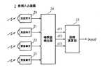
- FIG. 5is a block diagram showing an example of the configuration of the coordinate input device 2.
- receiving elements 20 to 23receive signals transmitted from the transmitting element 11 of the coordinate indicator 1 and output received signals at each position.
- the time difference detector 24detects the time difference between the received signals from the receiving elements 20-23.
- the time difference between the reception signal received by the reception element 21is dT1
- the time difference between the reception signal received by the reception element 22is dT2
- the reception element 23Numerical data with a time difference from the received signal received in step dT3 is output.
- the coordinate calculation unit 25multiplies the time differences dT1, dT2, and dT3 detected by the time difference detection unit 24 by the unit time in the time difference detection unit 24, the speed of light in the case of light, and the speed of sound in the case of sound. Differences d1, d2, and d3 are obtained, and solutions of simultaneous equations (Equations 1 to 3) based on the distance differences d1, d2, and d3 are obtained as described later, and the spatial position (x, y) of the coordinate indicator 1 is accordingly obtained. , Z).
- the receiving elements of the receiving elements 20 to 23are light receiving elements when the signal is based on light such as infrared rays, and are ultrasonic receiving elements when the signal is based on ultrasonic waves.
- the arrangement of the receiving elements 20 to 23 described aboveis an arrangement in which all the receiving elements do not ride on the same circumference.
- at any position on the coordinate input device 2 where the coordinate indicator 1 is placedin (Equation 1) to (Equation 3), at least one equation is based on the upper hyperboloid equation. Spatial coordinates are derived.
- the coordinate indicator 1 and the receiving elements 20 to 23are not all equidistant. Even if the body 1 is placed on any position on the coordinate input device 2, a unique spatial point can be obtained, thereby realizing a coordinate input device having stable measurement accuracy.
- the simultaneous equations composed of (Equation 1) to (Equation 3) for obtaining the spatial positionmay be obtained by an iterative numerical solution, but are not limited thereto.
- the values of the distances L1, L2, L3 and the angle ⁇ 3 between the receiving elementsare determined, so that the L1, L2, L3 and the angle ⁇ 3 are set as constants.
- the obtained solution (x, y, z) corresponding to the predetermined combination of the distance differences d1, d2, and d3is previously incorporated as a table, and the detected distance differences d1, d2, and d3 are calculated from the table values in the vicinity thereof.
- An approximate solutionmay be derived by interpolation. Thereby, the processing time and power consumption in deriving the solution of simultaneous equations can be suppressed.
- the transmission signalis a signal having a constant period
- the present inventionis not limited to this.
- modulationsuch as frequency modulation, phase modulation, and pulse width modulation may be added for transmission.
- additional informationfor example, switch operation information provided on the coordinate indicator 1, sensor information such as acceleration information from an acceleration sensor, and the like can be considered.
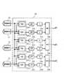
- FIG. 6is a block diagram showing an example of the circuit configuration of the time difference detection unit 24.
- the same components as those in FIG. 6are identical components as those in FIG. 6, the same components as those in FIG.
- a time-to-digital converter (TDC) 241has two inputs, a measurement start and a measurement end, and is a signal input to the start signal input terminal (denoted by S in the figure). And the time difference between the signals input to the end signal input terminal (indicated by E in the figure) are output as measured digital values. Signals from two receiving elements are input to two inputs of the time-digital converter 241, respectively.
- the delay circuit 242is inserted between the measurement end input terminal (stop signal input side) of the time-digital converter 241 and one receiving element, and delays the received signal by a predetermined time delay amount ⁇ .
- the low-pass filter 243equalizes the time difference between the received signals obtained for each period of the received signal from the time-digital converter, and the down sampler 244 outputs the time difference with a period longer than the period of the received signal.
- time difference detection unit 24having such a configuration, especially when light is used, the time difference due to the stroke difference is extremely short, so that it is difficult to obtain high detection accuracy with a large error in one detection. Good detection accuracy can be obtained by averaging.
- the subtractor 245obtains time differences dT1, dT2, and dT3 between the received signals by subtracting a value ⁇ corresponding to the delay time by the delay circuit 242 from the value of the time difference output from the down sampler 244. .
- the time-digital converter 241measures the delay of the signal from the measurement start input terminal S to the measurement end input terminal E. That can measure only the time difference in one direction (for example, the time difference from when the receiving element 20 receives the received signal until the receiving element 21 receives the received signal) makes it possible to measure both the positive and negative time differences. .
- the receiving element 21receives the received signal before the receiving element 20, it is possible to measure the time difference between the reception of both.
- the subtraction value ⁇ in the subtractor 245can be determined so as to cancel out the delay difference generated in the process of transmitting signals from both receiving elements to the time difference detecting unit 24, the receiving element, Errors due to the arrangement of the time difference detectors can also be reduced.
- the time difference detection unit 24inputs the received signal to the measurement end input terminal E of the time-digital converter via the delay circuit 242 having a predetermined time delay ⁇ , and the measurement result
- the delay time ⁇is subtracted from the value of the time difference between the positive and negative time delays, so that the time-to-digital conversion of a relatively short delay element array can be performed for received signals derived from the same transmission signal. Can be done with a vessel. For this reason, the circuit scale and power consumption are relatively small, which can contribute to the realization of a highly accurate coordinate input device.
- FIG. 7is a block diagram showing another example of the circuit configuration of the time difference detection unit 24.
- the same components as those in FIG. 7are identical to FIG. 7 in FIG. 7, the same components as those in FIG. 7 in FIG. 7, the same components as those in FIG. 7
- time-digital converters 2411 and 2412are paired, and their inputs are alternately switched.
- the delay determination unit 246selects a time difference obtained from a time difference detection path including a pair of time-digital converters 2411 and 2412, a low-pass filter 243, and a downsampler 244, and selects a positive or negative value corresponding thereto. Output as a time difference detected by adding a sign.
- the time difference detection unit 24can detect positive and negative time differences, and this detection can be performed with a relatively small circuit.
- time-to-digital converters 2411 and 2412are provided as a pair, but this time-to-digital converter is used as one unit, and the time-to-digital converter is connected to each period of the received signal.
- the same effectcan be obtained by detecting the input alternately.
- An example in which the input to the time-digital converter is alternately switched every period of the received signal as described abovewill be described with reference to FIG.
- FIG. 13is a block diagram showing still another example of the circuit configuration of the time difference detection unit 24.
- a switch 249is inserted between the time-digital converter 241 and the receiving elements 20 to 23, and a switching signal block 248 for outputting a switching signal indicating a signal period from the signal from the receiving element 20 is provided. It has been added.
- the switch 249periodically switches the input destinations of the two received signals input to the time-digital converter 241 in accordance with the switch signal from the switch signal block 248.
- the value in the cycle in which the effective value is obtainedcan be used in the subsequent processing.
- the low-pass filter 243 and the downsampler 244are described as separate blocks. However, the two functional blocks do not have to be independent, and are detected in the cycle of the transmission signal as described above. Any function that averages the time difference values and outputs the time difference values at a low frequency with a longer period may be used.
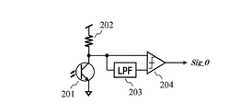
- FIG. 8is a circuit diagram showing an example of a circuit configuration when the receiving elements 20 to 23 are constituted by light receiving elements.
- a phototransistor 201 as a light receiving elementreceives an optical signal emitted from the light emitting element of the coordinate indicator 1 and converts it into a current.
- the light receiving elementis not limited to a phototransistor, and may be a photodiode or other photoelectric conversion element.
- the resistor 202is connected between the power supply and the phototransistor 201 and is used to measure a voltage according to the current flowing through the phototransistor 201.
- the phototransistor 201outputs a current when the light is incident, and outputs a low voltage level when the light is detected because no current flows when the light is not incident, and outputs a high voltage level when the light is not detected.
- the resistor 202may be replaced with a circuit that constitutes a constant current source.
- the low-pass filter 203has a cut-off characteristic for removing a signal having a predetermined period to be received, and equalizes the received signal to provide a reference level for signal detection.
- the comparator 204compares the reference level from the low-pass filter 203 with the received signal level from the phototransistor 201 and the resistor 202, and outputs the presence or absence of light as a digital value.
- FIG. 9is a schematic circuit diagram showing an example of a time-digital converter.
- the time-digital converteris connected to the measurement start input terminal S, a delay element array in which a number of delay elements having a constant delay are connected in series, the output of the delay element, and the measurement end input, respectively. It is composed of a large number of flip-flops that receive the signal from the terminal E, and a decoder that converts the output values from the large number of flip-flops into binary.
- the time-to-digital converterhas a delay line formed by connecting a plurality of delay elements on the start signal input side.
- the delay time of the delay elementis set to several picoseconds, for example.
- this time-digital converterWhen the measurement end signal E is input with a slight delay from the measurement start signal S in FIG. 10A, this signal delay relationship is defined as a positive time difference.
- This time-to-digital converteroperates on the basis of the rising edge of the input signal (indicated by an upward arrow in the figure). In this case, the rising edge of the measurement start signal S causes the delay element array to have a certain delay time. Then, when the rising edge of the measurement end signal E is input, the values of the delay sequence at that moment are simultaneously fetched by the flip-flops.
- the rising edge of the measurement start signal Sadvances through the delay line by the time difference (hatched area in the figure) between the rising edges of the measurement start signal S and the measurement end signal E, and the delay element from the input end side.
- the output of the delay elementis captured as 1, and the value of the delay element thereafter is captured as 0.
- the decoderconverts the value obtained by the output value 1 corresponding to the rising edge of the measurement start signal S from the input end side of the value fetched into the flip-flop into a binary value and outputs it.
- the time difference between the rising edges of the measurement start signal S and the measurement end signal Eis converted into a binary value and output.
- this signal delay relationshipis defined as a negative time difference.
- the time-digital converteris configured to measure a positive time difference as described above, the time-to-digital converter is not measured at the rising edge of the measurement end signal E that has entered earlier, but until the next incoming rising edge. Time difference (hatched area in the figure) is measured.
- the received signalis a signal having a fixed period
- the negative time differencemay be obtained by treating it as a phase difference in this way, the following problems arise.
- the time difference to be measuredbecomes large, there are cases where an effective value cannot be obtained if there are few delay element rows.
- providing a long delay element arraycauses an increase in circuit scale and power consumption, and accumulates errors due to the passage of the long delay string, resulting in a decrease in measurement accuracy.
- this modulation componentis not used because it is not a time difference measurement derived from the same transmission signal. It becomes an error of the time difference to measure.
- the time difference to be measuredis (distance difference) / (speed of light), which is an extremely short time.
- the coordinate input device 2detects the time difference for a specific combination of the received signals output from the receiving elements 20 to 23, and coordinates based on the detected time difference.
- the spatial coordinates of the indicator 1are calculated and the calculation result is output.
- FIG. 11is a schematic diagram of the electronic arithmetic device according to the second embodiment of the present invention.
- the same components as those in FIG. 11are identical to FIG. 11 and the same components as those in FIG. 11;
- the display panel 3is a flat panel display such as a liquid crystal display panel or an organic EL display panel.
- a display objectsuch as a cursor, a pointer, or a character is displayed on the display panel 3, and the coordinate input device 2 obtains spatial coordinates according to the spatial position of the coordinate indicator 1, and this coordinate instruction
- the display position of the display object on the screenis determined according to the spatial coordinates of the body 1.
- the display objectis moved on the display screen following the movement of the coordinate indicator 1.
- the operation on the display panel 3 according to the position or operation of the display objectis executed by an application process.
- the display panel 3is a 3D display panel
- the position of the display object in the depth directioncan also be displayed in accordance with the operation of the coordinate indicator 1.
- the display object on the 3D graphics displayed on the display panel 3 or the display object displayed on the 3D display panelcan be intuitively operated by the coordinate indicator 1, so that the user can A user interface that is easy to understand and has a low burden can be provided.
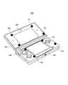
- FIG. 18is a schematic diagram of a game machine which is an example of an electronic arithmetic device.
- the game machine 300is a folding type and includes an upper screen 302 and a lower screen 303.
- receiving elements 320 to 323are arranged on the periphery of the upper screen 302. Among these, only the receiving element 323 is arranged at a position far from the upper screen 302. This is to prevent all four receiving elements from being located on the same circumference.
- the receiving element 333is arranged at a position far from the upper screen 302.
- the input to the display content of the upper screen 302is performed using the four receiving elements 320 to 323, and the lower screen 303 is displayed.
- the four receiving elements 330 to 333may be used.
- the spatial coordinates of the coordinate indicatormay be detected using eight receiving elements regardless of the display of both screens 302 and 303. Increasing the number of receiving elements used tends to increase the amount of computation, but can improve the accuracy of spatial coordinate detection.
- dT1time difference between the reception signals of the reception element 20 and the reception element 21
- dT2time difference between the reception signals of the reception element 20 and the reception element 22
- dT3time difference between the reception signals of the reception element 20 and the reception element 23
- the time differencethe time difference between the receiving element 20 and the remaining receiving elements 21 to 23 is obtained with the receiving element 20 as a reference. This is because the origin of the xyz orthogonal coordinate system is set to the point P0 (see FIG. 2) of the receiving element 20, so that the calculation of coordinates becomes easy.
- the combination of receiving elements for obtaining the time differenceis not limited to this.
- Three combinations of two arbitrary receiving elementsmay be selected from the four receiving elements 20 to 23, and the three selected time differences may be obtained.
- the time difference between the receiving elementsmay be obtained by a combination that appropriately finds the solution of the ternary cubic equation of (Equation 1) to (Equation 3).
- the number of receiving elementsis not limited to four or eight. Although it can be set to an appropriate number based on the required accuracy of the spatial coordinates, the amount of calculation allowed, etc., for example, the upper limit may be 32 (or 16).
- a coordinate input deviceincludes a time difference between at least four receiving units that receive light or sound emitted from a coordinate indicator at a time and a predetermined combination of the receiving units. And a coordinate calculation unit that calculates the spatial coordinates of the coordinate indicator based on the detected time difference.
- the receiving unitsmay be arranged on the same plane and not on the same circumference.
- the coordinate indicatormay include a light emitting element that emits light, and the receiving unit may receive light using a single light receiving element included therein.
- the coordinate indicatormay include an ultrasonic transmission element that emits an ultrasonic wave, and the reception unit may receive ultrasonic waves with a single ultrasonic reception element included in each.
- the detection unitreceives two reception signals indicating reception at two different reception units, outputs a digital signal indicating a time difference between the two received signals, and the time A delay circuit having a predetermined delay time inserted on the stop signal input side of the digital converter may be included.
- the detection unitreceives a reception signal indicating reception at the first reception unit and a reception signal indicating reception at the second reception unit, and indicates reception at the first reception unit.
- a first time-to-digital converterthat outputs a digital signal indicating a time difference from a reception time of a reception signal to a reception time of a reception signal indicating reception at the second reception unit; and a second reception unit
- a reception signal indicating reception at the first reception unit and a reception signal indicating reception at the first reception unitare respectively input, and from the reception point of the reception signal indicating reception at the second reception unit, the first reception unit
- An output unit that selectively outputs the digital signal Mutoshitemay be.
- the detection unitincludes a time-to-digital converter that receives two reception signals indicating reception in two different reception units and outputs a digital signal indicating a time difference between the two input reception signals. And a switch for periodically and alternately switching the input destinations of the two received signals input to the time-digital converter, and the coordinate calculation unit obtains an effective value indicating the calculated spatial coordinates. It is also possible to output a value in a different cycle.
- the receiving unitmay include a display panel arranged at the periphery, and a display object on the display panel may be displayed according to the spatial position of the coordinate indicator.
- the predetermined combinationmay be a combination of one of the at least four receiving units and a pair of the remaining receiving units.
- An electronic arithmetic deviceperforms predetermined processing based on the coordinate input device according to any one of claims 1 to 9 and the spatial coordinates calculated by the coordinate arithmetic unit of the coordinate input device.
- (11)In the coordinate input method according to the embodiment, at least four receiving units receive light or sound emitted from the coordinate indicator at a time, and received in a predetermined combination of the receiving units. A detection step for detecting the time difference, and a coordinate calculation step for calculating a spatial coordinate of the coordinate indicator based on the detected time difference.
- the coordinate input deviceis useful as a three-dimensional pointing device for inputting spatial (three-dimensional) coordinate information to a computer or the like. Further, the present invention can be applied to the use of a three-dimensional pointing device in a computer terminal or a computer / game device that performs spatial coordinate input in cooperation with display contents, particularly in the front space of the display panel.
Landscapes
- Engineering & Computer Science (AREA)
- General Engineering & Computer Science (AREA)
- Theoretical Computer Science (AREA)
- Physics & Mathematics (AREA)
- Human Computer Interaction (AREA)
- General Physics & Mathematics (AREA)
- Acoustics & Sound (AREA)
- Position Input By Displaying (AREA)
Abstract
Description
Translated fromJapanese本発明は、ポインター等の座標指示体の空間位置を検出し、その空間座標を出力する座標入力装置に関する。The present invention relates to a coordinate input device that detects the spatial position of a coordinate indicator such as a pointer and outputs the spatial coordinates.
従来の座標入力装置としては、座標指示体が備える発信素子から発信される超音波を、マイクを用いて発信された超音波の受信方向を検知することにより、座標指示体の空間座標を求めるものがある(特許文献1,2参照)。As a conventional coordinate input device, an ultrasonic wave transmitted from a transmitting element included in a coordinate indicator is used to obtain a spatial coordinate of the coordinate indicator by detecting a receiving direction of the ultrasonic wave transmitted using a microphone. (See Patent Documents 1 and 2).
図12は、特許文献2に記載された従来の座標入力装置の構成を示す模式図である。図12において、座標指示体500は超音波発信素子511を内蔵しており、座標入力装置600に向けて超音波を発信する。FIG. 12 is a schematic diagram showing a configuration of a conventional coordinate input device described in Patent Document 2. In FIG. 12, the coordinate indicator 500 includes an ultrasonic transmission element 511 and transmits ultrasonic waves toward the coordinate input device 600.
板状をした座標入力装置600は、その表面にそれぞれマイクからなる4つの受信素子520~523を有する。特許文献2では、これらの受信素子520~523が超音波の受信方向を検知することにより、座標指示体の空間座標を検出できるとしている。The plate-like coordinate input device 600 has four
ところで、本願発明者らは従来の受信方向から空間座標を検出する方法とは異なった手法によって座標指示体の空間座標を求めることを検討している。By the way, the inventors of the present application are considering obtaining the spatial coordinates of the coordinate indicator by a method different from the conventional method of detecting the spatial coordinates from the reception direction.
そこで、本願発明は空間座標を求める新しい手法を実現できる座標入力装置を提供することを目的とする。Therefore, an object of the present invention is to provide a coordinate input device capable of realizing a new method for obtaining spatial coordinates.
本発明に係る座標入力装置は、座標指示体から一時に放射された光または音を受信する少なくとも4つの受信部と、前記受信部のうちの所定の組み合わせにおいて受信した時点の時間差を検出する検出部と、検出された時間差に基づいて、前記座標指示体の空間座標を演算する座標演算部と、を備える。The coordinate input device according to the present invention detects at least four reception units that receive light or sound emitted from a coordinate indicator at a time and a time difference between the reception points in a predetermined combination of the reception units. And a coordinate calculation unit that calculates the spatial coordinates of the coordinate indicator based on the detected time difference.
本発明の座標入力装置によれば、複数の受信部にて受信した時間差を検出し、検出された時間差に基づいて座標指示体の空間座標を演算するという、空間座標を求める新しい手法を実現できる。According to the coordinate input device of the present invention, it is possible to realize a new method for obtaining a spatial coordinate by detecting a time difference received by a plurality of receiving units and calculating a spatial coordinate of a coordinate indicator based on the detected time difference. .
以下本発明の実施の形態について、図面を参照しながら説明する。
(実施の形態1)
図1は、本発明の実施の形態1における座標入力装置の模式図である。Embodiments of the present invention will be described below with reference to the drawings.
(Embodiment 1)
FIG. 1 is a schematic diagram of a coordinate input device according to Embodiment 1 of the present invention.
図1において、座標指示体1は、操作者により動かされるものであって、その空間的位置である空間座標を座標入力装置2に対して指し示す。In FIG. 1, a coordinate indicator 1 is moved by an operator, and indicates a spatial coordinate that is a spatial position to the coordinate input device 2.
座標指示体1には、空間位置の検出対象となる発信素子11が備えられている。この発信素子11は、光または音を空間上に放射する機能を備えており、具体的には、赤外線などの光を発する発光素子、または超音波を発信する超音波発信素子から構成される。The coordinate indicator 1 is provided with a transmitting
座標入力装置2は、後述の規則に従った配置で受信素子20~23を備える。これらの受信素子20~23は、発信素子11から放射される光または音をそれぞれ受信し、その受信信号を出力する。The coordinate input device 2 includes receiving
詳しくは後述するが、座標入力装置2では、各受信素子20~23の受信信号(この受信信号は、座標指示体1から一時に放射された信号を受信したことを示す。)のうちの特定の組合せについての受信時点の時間差を検出し、検出した時間差に基づいて、座標指示体1の空間座標を演算し、演算結果を出力することとなる。As will be described in detail later, in the coordinate input device 2, the reception signal of each of the receiving
図2は、上記受信素子20~23の配置と座標系の詳細を示す斜視図である。図3は、同じく上記受信素子20~23の配置と座標系の詳細を示すz軸方向から俯瞰した平面図である。図2及び図3において、図1と同じ構成要素については同じ符号を用い、説明を省略する。FIG. 2 is a perspective view showing the arrangement of the
図2及び図3において、xyz直交座標系の原点は受信素子20の位置に設定され、受信素子21は原点より距離L1のx軸上に、受信素子22は原点より距離L2のy軸上に配置され、受信素子23は原点より距離L3であり、x軸と角度α3(∠P1P0P3=α3)をなすxy平面上に配置されている。このように、受信素子20~23はxy平面上に配され、z軸は高さ方向を示している。2 and 3, the origin of the xyz orthogonal coordinate system is set to the position of the
更に図3に示す通り、受信素子20~23は、その全てが同一の円周上には位置しないように(乗らないように)配置されている。Further, as shown in FIG. 3, the
即ち、三つの受信素子20,21,22の夫々の位置P0,P1,P2を通る円周Cについて、第4の受信素子23は、位置P4のような円周C上に配置せず、円周Cから離れた位置P3に配置されている。That is, for the circumference C passing through the respective positions P0, P1, and P2 of the three receiving
図4は、座標指示体1の構成の一例を示すブロック図である。図4において、クロック生成部12は、所定周期の基準クロックを生成する。駆動部13は、クロック生成部12で生成された基準クロックに基づいて、音または光を発信素子11から放射する。ここで、発信素子11は、赤外線を放射する場合は、発光素子を用い、超音波を放射する場合は超音波発信素子を用いる。FIG. 4 is a block diagram showing an example of the configuration of the coordinate indicator 1. In FIG. 4, a
図5は、座標入力装置2の構成の一例を示すブロック図である。図5において、受信素子20~23は、座標指示体1の発信素子11から発信された信号を受信し、各位置での受信信号を出力する。FIG. 5 is a block diagram showing an example of the configuration of the coordinate input device 2. In FIG. 5, receiving
時間差検出部24は、受信素子20~23からの受信信号間の時間差を検出する。The
本構成例では、受信素子20の受信信号を基準として、受信素子21で受信した受信信号との間の時間差をdT1、受信素子22で受信した受信信号との間の時間差をdT2、受信素子23で受信した受信信号との間の時間差をdT3とする数値データを出力する。In this configuration example, with reference to the reception signal of the
座標演算部25は、時間差検出部24にて検出された時間差dT1,dT2,dT3それぞれに、時間差検出部24における単位時間と、光の場合は光速、音の場合には音速とを乗じて距離差d1,d2,d3を求め、後述の通りに、距離差d1,d2,d3に基づく連立方程式(数1~数3)の解を求め、それに従って座標指示体1の空間位置(x,y,z)が定められる。The
ここで、上記受信素子20~23の受信素子は、信号が赤外線などの光による場合は受光素子であり、超音波による場合は超音波受信素子である。Here, the receiving elements of the


即ち、時間差検出部24で検出された時間差を基に得られた距離差d1~d3にそれぞれ従った(数1)~(数3)を満たす点(x、y、z)を求めることで、座標指示体1の空間位置が判明するものである。That is, by obtaining points (x, y, z) that satisfy (Equation 1) to (Equation 3) according to the distance differences d1 to d3 obtained based on the time difference detected by the time
なお、(数1)~(数3)において空間位置を導出するにあたっては、上記垂直二等分面を挟んだ両側に解が存在することになり、一意に定まらないことになるとも思われるがそうではなく、距離差d1~d3の正負により、解の存在範囲を示す次の不等式(数4)~(数6)の条件を課すことにより正しい空間位置を導出することができる。In deriving the spatial position in (Equation 1) to (Equation 3), there will be solutions on both sides of the vertical bisector, which may not be uniquely determined. Instead, the correct spatial position can be derived by imposing the conditions of the following inequalities (Expression 4) to (Expression 6) indicating the existence range of the solutions based on whether the distance differences d1 to d3 are positive or negative.


上述の受信素子20~23の配置は、この課題に鑑みて、全ての受信素子が同一円周上に乗らない配置となっている。こうすることで、座標指示体1が座標入力装置2上の何れの位置に置かれても、(数1)~(数3)において、少なくとも一つの式が上段の双曲面の式に基づいて空間座標の導出が行われるようになる。In view of this problem, the arrangement of the receiving
かかる構成によれば、全ての受信素子が同一円周上には位置しないような配置とすることにより、座標指示体1と受信素子20~23とが全て等距離となることはなく、座標指示体1が座標入力装置2上の何れの位置に置かれても、一意な空間点を求めることができ、これにより安定した測定精度を有する座標入力装置を実現することができる。According to this configuration, by arranging the receiving elements so that all the receiving elements are not located on the same circumference, the coordinate indicator 1 and the receiving
なお、上記空間位置を求めるための(数1)~(数3)からなる連立方程式は、反復的な数値解法により解を求めてもよいがこれに限られない。The simultaneous equations composed of (Equation 1) to (Equation 3) for obtaining the spatial position may be obtained by an iterative numerical solution, but are not limited thereto.
例えば、受信素子20~23の配置が定まっている場合、それにより受信素子間の距離L1,L2,L3、角度α3の値は定まっているため、このL1,L2,L3、角度α3を定数として求めた、距離差d1,d2,d3の所定の組み合わせに対応する解(x,y,z)をテーブルとして予めに組み込み、検出した距離差d1,d2,d3について、その近傍のテーブル値からの内挿により近似解を導出してもよい。これにより、連立方程式の解の導出における処理時間、消費電力を抑えることができる。For example, when the arrangement of the receiving
なお、上記においては、受信素子20,21を通る直線P0P1と受信素子20,22を通る直線P0P2が直交する場合について記載したが、これに限定するものではなく、直線P0P1と直線P0P2が角度α2(∠P1P0P2=α2)を成して斜交するような場合においても同様に位置の検出は可能である。この場合の位置の算出は、上記と同様に(数7)~(数9)の解を求めることにより得られる。In the above description, the case where the straight line P0P1 passing through the receiving


例えば、空間座標以外の付加的な情報を送信するために、周波数変調、位相変調、パルス幅変調などの変調を加えて送信するようにしても構わない。この付加的な情報としては、例えば座標指示体1に設けられたスイッチの操作情報や、加速度センサーからの加速度情報などのセンサー情報などが考えられる。For example, in order to transmit additional information other than spatial coordinates, modulation such as frequency modulation, phase modulation, and pulse width modulation may be added for transmission. As this additional information, for example, switch operation information provided on the coordinate indicator 1, sensor information such as acceleration information from an acceleration sensor, and the like can be considered.
これにより、x,y,zの空間座標のみならず、上記付加的な情報を含む多様な情報(空間座標情報)を座標指示体1により指し示すことが可能となる。Thereby, not only the spatial coordinates of x, y, and z but also various information (spatial coordinate information) including the additional information can be indicated by the coordinate indicator 1.
図6は、上記時間差検出部24の回路構成の一例を示すブロック図ある。図6において、図5と同じ構成要素については同じ符号を用い、説明を省略する。FIG. 6 is a block diagram showing an example of the circuit configuration of the time
図6において、時間‐デジタル変換器(TDC:Time-to-Digital Converter)241は、計測開始と計測終了の二つの入力を持ち、開始信号入力端(図中、Sで標記)に入った信号と終了信号入力端(図中、Eで標記)に入った信号の時間差を、計測したデジタル値として出力するものである。時間-デジタル変換器241の二つの入力には、それぞれ二つの受信素子からの信号が入力されている。In FIG. 6, a time-to-digital converter (TDC) 241 has two inputs, a measurement start and a measurement end, and is a signal input to the start signal input terminal (denoted by S in the figure). And the time difference between the signals input to the end signal input terminal (indicated by E in the figure) are output as measured digital values. Signals from two receiving elements are input to two inputs of the time-
遅延回路242は、時間‐デジタル変換器241の計測終了入力端子(停止信号入力側)と一方の受信素子との間に挿入され、所定の時間遅延量τだけ受信信号を遅延させる。The
ローパスフィルタ243は、時間‐デジタル変換器より受信信号の周期毎に得られる受信信号間の時間差を平準化し、ダウンサンプラ244にて受信信号の周期より長い周期で時間差を出力している。The low-
かかる構成による時間差検出部24においては、特に光を用いた場合、行程差による時間差は極めて短いため、一度の検出では誤差が大きく高い検出精度を得ることが困難であるが、多数のサンプリング結果の平均化により良好な検出精度を得ることができる。In the time
減算器245は、ダウンサンプラ244から出力される時間差の値に対して、遅延回路242による遅延時間に相当する値τを減算することにより、受信信号間の時間差dT1、dT2、dT3を求めている。The
かかる遅延回路242と減算器245を加えた構成により、時間‐デジタル変換器241は、計測開始入力端Sから計測終了入力端Eへの信号の遅れを計測するものであるため、二つの信号間の一方向の時間差(例えば、受信素子20が受信信号を受信してから受信素子21が受信信号を受信するまでの時間差)しか計測できないものが、正負双方の時間差を計測することを可能としている。With the configuration in which the
つまり、例えば、受信素子21が受信素子20よりも先に受信信号を受信したとしても、両者の受信の時間差を計測することが可能となる。That is, for example, even if the receiving
更に、この構成によれば、両受信素子から時間差検出部24に信号を伝達する過程で生じる遅延差も相殺するように、減算器245での減算値τを定めることができるため、受信素子、時間差検出部の配置に起因する誤差を低減することもできる。Furthermore, according to this configuration, since the subtraction value τ in the
図6で説明した構成によれば、時間差検出部24において、時間‐デジタル変換器の計測終了入力端Eに対して所定の時間遅延τの遅延回路242を介して受信信号を入力し、測定結果の時間差の値から遅延時間τを減算する構成とすることにより、正負双方の時間遅延の計測が、同一の送信信号に由来する受信信号に対して、比較的短い遅延素子列の時間‐デジタル変換器で行える。このため、回路規模、消費電力が比較的小さく、高精度の座標入力装置の実現に寄与できる。According to the configuration described with reference to FIG. 6, the time
図7は、上記時間差検出部24の回路構成の別の一例を示すブロック図ある。図7において、図6と同じ構成要素については同じ符号を用い、説明を省略する。FIG. 7 is a block diagram showing another example of the circuit configuration of the time
図7において、時間‐デジタル変換器2411、2412は対をなし、その入力について交互に入れ替えた構成となっている。In FIG. 7, time-
遅延判定部246は、一対の時間‐デジタル変換器2411、2412とローパスフィルタ243、ダウンサンプラ244からなる時間差検出路から得られた時間差について、値が小さい方を選択すると共に、それに対応した正負の符号を付けて検出した時間差として出力する。The
かかる構成により、時間差検出部24において正負の時間差の検出を可能とし、この検出を比較的小規模な回路で行うことができる。With this configuration, the time
なお、本構成においては、対を成す二つの時間‐デジタル変換器2411、2412を備えているが、この時間‐デジタル変換器を一つとし、受信信号の周期毎に時間‐デジタル変換器への入力を交互に入れ替えて検出することで同様の効果を得ることができる。このように、受信信号の周期毎に時間‐デジタル変換器への入力を交互に入れ替える例を図13を用いて説明する。In this configuration, two time-to-
図13は、上記時間差検出部24の回路構成の更に別の一例を示すブロック図ある。FIG. 13 is a block diagram showing still another example of the circuit configuration of the time
図13において、時間‐デジタル変換器241と受信素子20~23との間には、切替器249が挿入され、受信素子20からの信号から信号期間を示す切替信号を出力する切替信号ブロック248が加えられている。In FIG. 13, a
切替器249は、切替信号ブロック248からの切替信号に従い、時間-デジタル変換器241へ入力される2つの受信信号の入力先を、周期的に交互に切り替える。The
かかる構成によれば、時間-デジタル変換器241が出力する切替に応じた2種類の値のうち、有効な値が得られた周期における値の方を後続する処理において用いることができる。According to such a configuration, of the two types of values corresponding to the switching output from the time-
なお、上記説明においてローパスフィルタ243とダウンサンプラ244は、個別のブロックとして説明しているが、この二つの機能ブロックが独立している必要はなく、上記の通り、送信信号の周期で検出される時間差値を平均化し、より長い周期の低周波数で時間差値を出力する機能をもつものであればよい。In the above description, the low-
図8は、受信素子20~23が受光素子によって構成される場合の回路構成の一例を示す回路図である。図8において、受光素子としてのフォトトランジスタ201は、座標指示体1の発光素子から放射された光信号を受光し電流に変換する。なお、この受光素子はフォトトランジスタに限るものではなく、フォトダイオード、その他の光電変換素子であってもよい。抵抗202は、電源とフォトトランジスタ201の間に接続され、フォトトランジスタ201の流す電流に従った電圧を測定するためのものである。ここで、フォトトランジスタ201は光が入射した場合には電流を流し、光が入射しない場合は電流を流さないため光を検出したとき低電圧レベルを、光が検出されないとき高電圧レベルを出力するものである。なお、この抵抗202は、定電流源を構成する回路に置き換えられてもよい。ローパスフィルタ203は、受信する所定周期の信号を除去するカットオフ特性をもち受信信号を平準化して信号検出のための参照レベルを与える。比較器204は、ローパスフィルタ203からの参照レベルとフォトトランジスタ201と抵抗202からの受信信号レベルとを比較し、光の有無をデジタル値として出力する。FIG. 8 is a circuit diagram showing an example of a circuit configuration when the receiving
図9は、時間‐デジタル変換器の一例を示す概略回路図である。図9において、時間‐デジタル変換器は、計測開始入力端Sに接続され、多数の一定の遅延を持つ遅延素子が直列に接続された遅延素子列と、それぞれ遅延素子の出力と、計測終了入力端Eからの信号と、を入力とする多数のフリップフロップと、多数のフリップフロップからの出力値をバイナリに変換するデコーダから構成される。FIG. 9 is a schematic circuit diagram showing an example of a time-digital converter. In FIG. 9, the time-digital converter is connected to the measurement start input terminal S, a delay element array in which a number of delay elements having a constant delay are connected in series, the output of the delay element, and the measurement end input, respectively. It is composed of a large number of flip-flops that receive the signal from the terminal E, and a decoder that converts the output values from the large number of flip-flops into binary.
このように、時間‐デジタル変換器は、その開始信号入力側に遅延素子を複数段連ねてなるディレイラインを有する。なお、遅延素子の遅延時間は例えば数ピコ秒に設定される。Thus, the time-to-digital converter has a delay line formed by connecting a plurality of delay elements on the start signal input side. The delay time of the delay element is set to several picoseconds, for example.
この時間‐デジタル変換器の動作を図10のタイミング図を用いて説明する。図10(A)の計測開始信号Sより計測終了信号Eが僅かに遅れて入力される場合、この信号遅延の関係を正の時間差と定義する。本時間‐デジタル変換器は、入力信号の立ち上がりエッジを基準に動作するもので(図中、上向き矢印で記載)、この場合において、計測開始信号Sの立ち上がりエッジは遅延素子列を一定の遅延時間を持って伝播していく、次に計測終了信号Eの立ち上がりエッジが入ると、フリップフロップによりその瞬間の遅延列の値が一斉に取り込まれる。このとき、計測開始信号Sの立ち上がりエッジは、計測開始信号Sと計測終了信号Eの立ち上がりエッジの時間差の分(図中、ハッチング領域)だけ遅延列を進んでおり、入力端側からその遅延素子までの遅延素子の出力が1として取り込まれ、それ以降の遅延素子の値は0が取り込まれる。デコーダは、フリップフロップに取り込まれた値について、計測開始信号Sの立ち上がりエッジに相当する出力値1が入力端側から進んだ量をバイナリ値に変換して出力する。これにより、計測開始信号Sと計測終了信号Eの立ち上がりエッジの時間差がバイナリ値に変換され、出力されている。The operation of this time-digital converter will be described with reference to the timing chart of FIG. When the measurement end signal E is input with a slight delay from the measurement start signal S in FIG. 10A, this signal delay relationship is defined as a positive time difference. This time-to-digital converter operates on the basis of the rising edge of the input signal (indicated by an upward arrow in the figure). In this case, the rising edge of the measurement start signal S causes the delay element array to have a certain delay time. Then, when the rising edge of the measurement end signal E is input, the values of the delay sequence at that moment are simultaneously fetched by the flip-flops. At this time, the rising edge of the measurement start signal S advances through the delay line by the time difference (hatched area in the figure) between the rising edges of the measurement start signal S and the measurement end signal E, and the delay element from the input end side. Until then, the output of the delay element is captured as 1, and the value of the delay element thereafter is captured as 0. The decoder converts the value obtained by the output value 1 corresponding to the rising edge of the measurement start signal S from the input end side of the value fetched into the flip-flop into a binary value and outputs it. As a result, the time difference between the rising edges of the measurement start signal S and the measurement end signal E is converted into a binary value and output.
次に、図10(B)の計測開始信号Sより計測終了信号Eが僅かに早く入力される場合、この信号遅延の関係を負の時間差と定義する。この場合においては、上記の通り時間‐デジタル変換器は、正の時間差を計測する構成であるため、早く入ってきた計測終了信号Eの立ち上がりエッジで計測されず、次に入ってくる立ち上がりエッジまでの時間差(図中、ハッチング領域)が計測される。Next, when the measurement end signal E is input slightly earlier than the measurement start signal S in FIG. 10B, this signal delay relationship is defined as a negative time difference. In this case, since the time-digital converter is configured to measure a positive time difference as described above, the time-to-digital converter is not measured at the rising edge of the measurement end signal E that has entered earlier, but until the next incoming rising edge. Time difference (hatched area in the figure) is measured.
ここで、受信信号が一定周期の信号である場合は、上記の通り次の計測終了信号Eの立ち上がりエッジによる時間差を計測して、周期を差し引くことで負の時間差を求めることが可能である。このように位相差として取り扱うことで負の時間差を求めても良いが、次の様な課題が生じる。Here, when the received signal is a signal having a fixed period, it is possible to obtain a negative time difference by measuring the time difference due to the rising edge of the next measurement end signal E and subtracting the period as described above. Although the negative time difference may be obtained by treating it as a phase difference in this way, the following problems arise.
計測する時間差が大きくなるため、遅延素子の列が少ないと有効な値が得られないことがある。とはいえ、長い遅延素子の列を設けると、回路規模、消費電力の増大を招くと共に、長い遅延列の通過により誤差を蓄積し測定精度の低下を招く。また、上述の通り、空間位置以外の情報を伝送するため、送信信号に周波数変調或いは位相変調など時間軸方向の変調が加えられる場合、同一の送信信号に由来する時間差計測でないため、この変調成分が計測する時間差の誤差となる。特に送信素子として発光素子を用いる場合には、計測する時間差は、(距離差)/(光速)で極めて短い時間であるため、これらの誤差は著しい測定誤差となって現れる。Since the time difference to be measured becomes large, there are cases where an effective value cannot be obtained if there are few delay element rows. However, providing a long delay element array causes an increase in circuit scale and power consumption, and accumulates errors due to the passage of the long delay string, resulting in a decrease in measurement accuracy. Further, as described above, in order to transmit information other than the spatial position, when modulation in the time axis direction such as frequency modulation or phase modulation is applied to the transmission signal, this modulation component is not used because it is not a time difference measurement derived from the same transmission signal. It becomes an error of the time difference to measure. In particular, when a light emitting element is used as the transmitting element, the time difference to be measured is (distance difference) / (speed of light), which is an extremely short time.
以上のように、本実施の形態1に係る座標入力装置2では、受信素子20~23から出力された受信信号のうちの特定の組合せについての時間差を検出し、検出した時間差に基づいて、座標指示体1の空間座標を演算し、演算結果を出力する。これにより、回路規模、消費電力が比較的小さく、高精度な空間座標の演算を実現できる。As described above, the coordinate input device 2 according to the first embodiment detects the time difference for a specific combination of the received signals output from the receiving
(実施の形態2)
図11は、本発明の実施の形態2の電子演算装置の模式図である。図11において、図1と同じ構成要素については同じ符号を用い、説明を省略する。(Embodiment 2)
FIG. 11 is a schematic diagram of the electronic arithmetic device according to the second embodiment of the present invention. In FIG. 11, the same components as those in FIG.
図11において、表示パネル3は、液晶表示パネルや有機EL表示パネルなどのフラットパネルディスプレイである。本構成においては、表示パネル3上にカーソル、ポインタ、或いはキャラクターなどの表示物が表示されており、座標入力装置2により座標指示体1の空間位置に従った空間座標が求められ、この座標指示体1の空間座標に準じて表示物の画面上での表示位置を定めている。これにより、表示物は座標指示体1の動きに追従して表示画面上を動かされる。更に、この表示物の位置或いは動作に従った表示パネル3上での動作がアプリケーション・プロセスによって実行されるものである。特に、表示パネル3が3D表示パネルである場合、上記表示物の奥行き方向の位置も座標指示体1の動作に合わせて表示することができる。In FIG. 11, the
かかる構成によれば、表示パネル3に表示される3Dグラフィックス上の表示物、或いは、3D表示パネルに表示される表示物を、座標指示体1により直感的に操作することができ、ユーザーにとり分かり易く、負担の少ない良好なユーザーインターフェースを提供することができる。According to such a configuration, the display object on the 3D graphics displayed on the
この他にも電子演算装置の例としては次のようなゲーム機が考えられる。In addition to the above, the following game machines can be considered as examples of the electronic arithmetic unit.
図18は、電子演算装置の一例であるゲーム機の模式図である。FIG. 18 is a schematic diagram of a game machine which is an example of an electronic arithmetic device.
ゲーム機300は、折り畳み型をしており、上画面302と下画面303を備える。The
上画面302の周縁には、4つの受信素子320~323が配置されている。このうち受信素子323だけは、上画面302から遠い位置に配置されている。
これは4つの受信素子のすべてが同一円周上に位置しないようにするためである。Four receiving
This is to prevent all four receiving elements from being located on the same circumference.
また、下画面303の周囲には、4つの受信素子330~333が配置されている。このうち受信素子333だけは、上画面302から遠い位置に配置されている。Further, around the
このようなゲーム機において図示しない座標指示体の空間座標を検出する場合には、上画面302の表示内容に対する入力の際には、4つの受信素子320~323を用いて行い、下画面303の表示内容に対する入力の際には、4つの受信素子330~333を用いて行うとしてもよい。In such a game machine, when detecting the spatial coordinates of a coordinate indicator (not shown), the input to the display content of the
また、両画面302,303の表示とは関係なく、8つの受信素子を用いて座標指示体の空間座標を検出するとしても構わない。用いる受信素子の数を増やすことで、演算量の増加を招く傾向があるものの、空間座標の検出精度を高めることができる。Also, the spatial coordinates of the coordinate indicator may be detected using eight receiving elements regardless of the display of both
<補足1>
(1)時間差を求める受信素子の組み合わせ
実施の形態1では、
dT1・・・受信素子20と受信素子21との受信信号の時間差
dT2・・・受信素子20と受信素子22との受信信号の時間差
dT3・・・受信素子20と受信素子23との受信信号の時間差
として、受信素子20を基準としてこの受信素子20と残りの受信素子21~23との時間差を求めるとしている。これはxyz直交座標系の原点を受信素子20の点P0(図2参照)としたことから、座標の計算が容易になるためである。<Supplement 1>
(1) Combination of receiving elements for obtaining time difference In the first embodiment,
dT1: time difference between the reception signals of the
もっとも、時間差を求める受信素子の組み合わせはこれに限られない。4つの受信素子20~23から、任意の受信素子二つの組み合わせを三種類選び、選んだ三種類の時間差を求めるとしても構わない。ようするに、(数1)~(数3)の三元三次方程式の解が適当に求まるような組み合わせで、受信素子間の時間差を求めるようにすればよい。However, the combination of receiving elements for obtaining the time difference is not limited to this. Three combinations of two arbitrary receiving elements may be selected from the four receiving
また、受信素子の個数は、4つや8つに限られるものではない。空間座標の必要な精度や許容される演算量などに基づいて適当な数に設定することができるが、例えばその上限は32個(あるいは16個)とすることが考えられる。Also, the number of receiving elements is not limited to four or eight. Although it can be set to an appropriate number based on the required accuracy of the spatial coordinates, the amount of calculation allowed, etc., for example, the upper limit may be 32 (or 16).
<補足2>
本実施の形態は、次の態様を含むものである。
(1)実施の形態に係る座標入力装置は、座標指示体から一時に放射された光または音を受信する少なくとも4つの受信部と、前記受信部のうちの所定の組み合わせにおいて受信した時点の時間差を検出する検出部と、検出された時間差に基づいて、前記座標指示体の空間座標を演算する座標演算部と、を備える。
(2)前記受信部は全て同一の平面上にあって、かつ、同一の円周上に位置しないように配置されているとしても構わない。<Supplement 2>
The present embodiment includes the following aspects.
(1) A coordinate input device according to an embodiment includes a time difference between at least four receiving units that receive light or sound emitted from a coordinate indicator at a time and a predetermined combination of the receiving units. And a coordinate calculation unit that calculates the spatial coordinates of the coordinate indicator based on the detected time difference.
(2) The receiving units may be arranged on the same plane and not on the same circumference.
この構成によれば、少なくとも一つの受信部は同一円周上に位置しない配置であるため、この円周の中心を足とする垂線上に座標指示体が置かれたとしても、全ての受信部から等距離となることはなく、高さの検出が可能であり、安定した空間位置の検出が可能となる。
(3)前記座標指示体は、光を放射する発光素子を有し、前記受信部は、それぞれが有する単一の受光素子により光を受信するとしても構わない。According to this configuration, since at least one receiving unit is arranged not to be located on the same circumference, even if a coordinate indicator is placed on a vertical line with the center of this circumference as a foot, all the receiving units Therefore, the height can be detected and the stable spatial position can be detected.
(3) The coordinate indicator may include a light emitting element that emits light, and the receiving unit may receive light using a single light receiving element included therein.
この構成によれば、各受信部の単一の受信素子のみで受信するため受信部に係わるサイズ、コスト、受信素子の駆動、及び信号解析に係る消費電力などを低減することに寄与できる。
(4)前記座標指示体は、超音波を放射する超音波発信素子を有し、前記受信部は、それぞれが有する単一の超音波受信素子により超音波を受信するとしても構わない。According to this configuration, since reception is performed by only a single receiving element of each receiving unit, it is possible to contribute to reducing the size, cost, driving of the receiving element, power consumption related to signal analysis, and the like related to the receiving unit.
(4) The coordinate indicator may include an ultrasonic transmission element that emits an ultrasonic wave, and the reception unit may receive ultrasonic waves with a single ultrasonic reception element included in each.
この構成によれば、各受信部の単一の受信素子のみで受信するため受信部に係わるサイズ、コスト、受信素子の駆動、及び信号解析に係る消費電力などを低減することに寄与できる。
(5)前記検出部は、2つの異なる受信部における受信を示す2つの受信信号が入力され、入力された2つの受信信号の時間差を示すデジタル信号を出力する時間-デジタル変換器と、前記時間‐デジタル変換器の停止信号入力側に挿入された所定の遅延時間をもつ遅延回路とを有するとしても構わない。
(6)前記検出部は、第1の受信部での受信を示す受信信号と第2の受信部での受信を示す受信信号とがそれぞれ入力され、前記第1の受信部での受信を示す受信信号の受信時点から、前記第2の受信部での受信を示す受信信号の受信時点までの時間差を示すデジタル信号を出力する第1の時間-デジタル変換器と、前記第2の受信部での受信を示す受信信号と前記第1の受信部での受信を示す受信信号とがそれぞれ入力され、前記第2の受信部での受信を示す受信信号の受信時点から、前記第1の受信部での受信を示す受信信号の受信時点までの時間差を示すデジタル信号を出力する第2の時間-デジタル変換器と、第1および第2の時間-デジタル変換器のうち、より小さい値の時間差を示すデジタル信号を選択的に出力する出力部とを含むとしても構わない。
(7)前記検出部は、2つの異なる受信部における受信を示す2つの受信信号が入力され、入力された2つの受信信号の時間差を示すデジタル信号を出力する時間-デジタル変換器を含み、さらに、前記時間-デジタル変換器へ入力される2つの受信信号の入力先を、周期的に交互に切り替える切替器を備え、前記座標演算部は、演算した前記空間座標を示す有効な値が得られた周期における値を出力するとしても構わない。
(8)前記受信部が周縁に配された表示パネルを備え、表示パネル上の表示物が前記座標指示体の空間位置に従って表示されるとしても構わない。
(9)前記所定の組み合わせとは、前記少なくとも4つの受信部のうちの1つの受信部と、残りの受信部との一対をそれぞれ組み合わせたものであるとしても構わない。
(10)実施の形態に係る電子演算装置は、請求項1~9の何れかに記載の座標入力装置と、前記座標入力装置の座標演算部により演算された空間座標を基に所定の処理を行うアプリケーション・プロセスと、を備える。
(11)実施の形態に係る座標入力方法は、座標指示体から一時に放射された光または音を、少なくとも四つの受信部において受信する受信ステップと、前記受信部のうちの所定の組み合わせにおいて受信した時間差を検出する検出ステップと、検出された時間差に基づいて、前記座標指示体の空間座標を演算する座標演算ステップと、を含む。According to this configuration, since reception is performed by only a single receiving element of each receiving unit, it is possible to contribute to reducing the size, cost, driving of the receiving element, power consumption related to signal analysis, and the like related to the receiving unit.
(5) The detection unit receives two reception signals indicating reception at two different reception units, outputs a digital signal indicating a time difference between the two received signals, and the time A delay circuit having a predetermined delay time inserted on the stop signal input side of the digital converter may be included.
(6) The detection unit receives a reception signal indicating reception at the first reception unit and a reception signal indicating reception at the second reception unit, and indicates reception at the first reception unit. A first time-to-digital converter that outputs a digital signal indicating a time difference from a reception time of a reception signal to a reception time of a reception signal indicating reception at the second reception unit; and a second reception unit A reception signal indicating reception at the first reception unit and a reception signal indicating reception at the first reception unit are respectively input, and from the reception point of the reception signal indicating reception at the second reception unit, the first reception unit Between the second time-digital converter that outputs a digital signal indicating the time difference up to the reception time of the received signal indicating reception at the first time-digital converter and the first and second time-digital converters. An output unit that selectively outputs the digital signal Mutoshite may be.
(7) The detection unit includes a time-to-digital converter that receives two reception signals indicating reception in two different reception units and outputs a digital signal indicating a time difference between the two input reception signals. And a switch for periodically and alternately switching the input destinations of the two received signals input to the time-digital converter, and the coordinate calculation unit obtains an effective value indicating the calculated spatial coordinates. It is also possible to output a value in a different cycle.
(8) The receiving unit may include a display panel arranged at the periphery, and a display object on the display panel may be displayed according to the spatial position of the coordinate indicator.
(9) The predetermined combination may be a combination of one of the at least four receiving units and a pair of the remaining receiving units.
(10) An electronic arithmetic device according to an embodiment performs predetermined processing based on the coordinate input device according to any one of claims 1 to 9 and the spatial coordinates calculated by the coordinate arithmetic unit of the coordinate input device. An application process to perform.
(11) In the coordinate input method according to the embodiment, at least four receiving units receive light or sound emitted from the coordinate indicator at a time, and received in a predetermined combination of the receiving units. A detection step for detecting the time difference, and a coordinate calculation step for calculating a spatial coordinate of the coordinate indicator based on the detected time difference.
本発明にかかる座標入力装置は、コンピュータ等に対して空間(3次元)座標情報を入力する3次元ポインティング装置等として有用である。また、特に表示パネルの前面空間において、表示内容と連携した空間座標入力を行うコンピュータ端末、或いはコンピュータ・ゲーム装置等における3次元ポインティング装置の用途にも応用が可能である。The coordinate input device according to the present invention is useful as a three-dimensional pointing device for inputting spatial (three-dimensional) coordinate information to a computer or the like. Further, the present invention can be applied to the use of a three-dimensional pointing device in a computer terminal or a computer / game device that performs spatial coordinate input in cooperation with display contents, particularly in the front space of the display panel.
1 座標指示体
2 座標入力装置
3 表示パネル
11 発信素子
12 クロック生成部
13 駆動部
20、21、22、23 受信素子
24 時間差検出部
25 座標演算部
241、2411、2412 時間‐デジタル変換器
242 遅延素子(遅延回路)
243 ローパスフィルタ
244 ダウンサンプラ
245 減算器
246 遅延判定部
201 フォトトランジスタ
202 抵抗
203 ローパスフィルタ
204 比較器
300 ゲーム機(電子演算装置の一例)DESCRIPTION OF SYMBOLS 1 Coordinate indicator 2 Coordinate
243 Low-
Claims (11)
Translated fromJapanese前記受信部のうちの所定の組み合わせにおいて受信した時点の時間差を検出する検出部と、
検出された時間差に基づいて、前記座標指示体の空間座標を演算する座標演算部と、
を備える座標入力装置。At least four receiving units for receiving light or sound emitted from the coordinate indicator at one time;
A detection unit for detecting a time difference at the time of reception in a predetermined combination of the reception units;
A coordinate calculation unit that calculates the spatial coordinates of the coordinate indicator based on the detected time difference;
A coordinate input device comprising:
前記受信部は、それぞれが有する単一の受光素子により光を受信する
請求項1または2に記載の座標入力装置。The coordinate indicator has a light emitting element that emits light,
The coordinate input device according to claim 1, wherein the receiving unit receives light by a single light receiving element included in each receiving unit.
前記受信部は、それぞれが有する単一の超音波受信素子により超音波を受信する
請求項1または2に記載の座標入力装置。The coordinate indicator has an ultrasonic transmission element that emits ultrasonic waves,
The coordinate input device according to claim 1, wherein each of the receiving units receives ultrasonic waves by a single ultrasonic receiving element included in each of the receiving units.
前記時間‐デジタル変換器の停止信号入力側に挿入された所定の遅延時間をもつ遅延回路とを有することを特徴とする
請求項1~4の何れかに記載の座標入力装置。The detection unit receives two reception signals indicating reception at two different reception units, and outputs a digital signal indicating a time difference between the two input reception signals; and a time-digital converter;
5. The coordinate input device according to claim 1, further comprising a delay circuit having a predetermined delay time inserted on a stop signal input side of the time-digital converter.
第1の受信部での受信を示す受信信号と第2の受信部での受信を示す受信信号とがそれぞれ入力され、前記第1の受信部での受信を示す受信信号の受信時点から、前記第2の受信部での受信を示す受信信号の受信時点までの時間差を示すデジタル信号を出力する第1の時間-デジタル変換器と、
前記第2の受信部での受信を示す受信信号と前記第1の受信部での受信を示す受信信号とがそれぞれ入力され、前記第2の受信部での受信を示す受信信号の受信時点から、前記第1の受信部での受信を示す受信信号の受信時点までの時間差を示すデジタル信号を出力する第2の時間-デジタル変換器と、
第1および第2の時間-デジタル変換器のうち、より小さい値の時間差を示すデジタル信号を選択的に出力する出力部とを含む
ことを特徴とする
請求項1~4の何れかに記載の座標入力装置。The detector is
A reception signal indicating reception at the first reception unit and a reception signal indicating reception at the second reception unit are respectively input, and from the reception time of the reception signal indicating reception at the first reception unit, A first time-to-digital converter that outputs a digital signal indicating a time difference until a reception time point of a reception signal indicating reception at the second reception unit;
A reception signal indicating reception at the second reception unit and a reception signal indicating reception at the first reception unit are respectively input, and from the reception time point of the reception signal indicating reception at the second reception unit. A second time-to-digital converter that outputs a digital signal indicating a time difference until a reception time point of a reception signal indicating reception at the first reception unit;
The output unit according to any one of claims 1 to 4, further comprising: an output unit that selectively outputs a digital signal indicating a time difference of a smaller value among the first and second time-digital converters. Coordinate input device.
さらに、前記時間-デジタル変換器へ入力される2つの受信信号の入力先を、周期的に交互に切り替える切替器を備え、
前記座標演算部は、演算した前記空間座標を示す有効な値が得られた周期における値を出力する
ことを特徴とする請求項1~4の何れかに記載の座標入力装置。The detection unit includes a time-to-digital converter that receives two reception signals indicating reception at two different reception units and outputs a digital signal indicating a time difference between the two input reception signals.
Furthermore, a switching device that periodically and alternately switches the input destinations of the two reception signals input to the time-digital converter,
5. The coordinate input device according to claim 1, wherein the coordinate calculation unit outputs a value in a cycle in which an effective value indicating the calculated spatial coordinate is obtained.
請求項1~7の何れかに記載の座標入力装置。The coordinate input according to any one of claims 1 to 7, wherein the receiving unit includes a display panel arranged at a peripheral edge, and a display object on the display panel is displayed according to a spatial position of the coordinate indicator. apparatus.
ことを特徴とする請求項1~8の何れかに記載の座標入力装置。The predetermined combination is a combination of one of the at least four receiving units and a pair of the remaining receiving units, respectively. The coordinate input device described.
前記座標入力装置の座標演算部により演算された空間座標を基に所定の処理を行うアプリケーション・プロセスと、
を備えることを特徴とする電子演算装置。A coordinate input device according to any one of claims 1 to 9,
An application process for performing predetermined processing based on the spatial coordinates calculated by the coordinate calculation unit of the coordinate input device;
An electronic arithmetic device comprising:
前記受信部のうちの所定の組み合わせにおいて受信した時間差を検出する検出ステップと、
検出された時間差に基づいて、前記座標指示体の空間座標を演算する座標演算ステップと、
を含む座標入力方法。A reception step of receiving light or sound emitted from the coordinate indicator at a time in at least four receiving units;
A detecting step of detecting a time difference received in a predetermined combination of the receiving units;
A coordinate calculation step for calculating a spatial coordinate of the coordinate indicator based on the detected time difference;
Coordinate input method including
Applications Claiming Priority (2)
| Application Number | Priority Date | Filing Date | Title |
|---|---|---|---|
| JP2012227696AJP2016001353A (en) | 2012-10-15 | 2012-10-15 | Coordinate input device, electronic operation device and coordinate input method |
| JP2012-227696 | 2012-10-15 |
Publications (1)
| Publication Number | Publication Date |
|---|---|
| WO2014061242A1true WO2014061242A1 (en) | 2014-04-24 |
Family
ID=50487821
Family Applications (1)
| Application Number | Title | Priority Date | Filing Date |
|---|---|---|---|
| PCT/JP2013/006064WO2014061242A1 (en) | 2012-10-15 | 2013-10-10 | Coordinate input device, electronic calculation device and coordinate input method |
Country Status (2)
| Country | Link |
|---|---|
| JP (1) | JP2016001353A (en) |
| WO (1) | WO2014061242A1 (en) |
Cited By (2)
| Publication number | Priority date | Publication date | Assignee | Title |
|---|---|---|---|---|
| JP2016024521A (en)* | 2014-07-17 | 2016-02-08 | Necプラットフォームズ株式会社 | Information processing system, information processing device, information processing method, information processing program, and stylus pen |
| CN112328126A (en)* | 2020-10-16 | 2021-02-05 | 上海紫钥信息技术有限公司 | System and method for judging screen shooting of ejection toy |
Families Citing this family (1)
| Publication number | Priority date | Publication date | Assignee | Title |
|---|---|---|---|---|
| JP2021111142A (en)* | 2020-01-10 | 2021-08-02 | 株式会社東芝 | Arithmetic logic unit |
Citations (4)
| Publication number | Priority date | Publication date | Assignee | Title |
|---|---|---|---|---|
| JPH07244147A (en)* | 1994-03-04 | 1995-09-19 | Nippon Telegr & Teleph Corp <Ntt> | Position measuring device and portable information terminal |
| JPH08166846A (en)* | 1994-12-15 | 1996-06-25 | Fujitsu Ltd | Ultrasonic coordinate input device |
| JPH08286817A (en)* | 1995-04-17 | 1996-11-01 | Canon Inc | Coordinate input device |
| WO2012063387A1 (en)* | 2010-11-10 | 2012-05-18 | パナソニック株式会社 | Non-contact position sensing device and non-contact position sensing method |
- 2012
- 2012-10-15JPJP2012227696Apatent/JP2016001353A/enactivePending
- 2013
- 2013-10-10WOPCT/JP2013/006064patent/WO2014061242A1/enactiveApplication Filing
Patent Citations (4)
| Publication number | Priority date | Publication date | Assignee | Title |
|---|---|---|---|---|
| JPH07244147A (en)* | 1994-03-04 | 1995-09-19 | Nippon Telegr & Teleph Corp <Ntt> | Position measuring device and portable information terminal |
| JPH08166846A (en)* | 1994-12-15 | 1996-06-25 | Fujitsu Ltd | Ultrasonic coordinate input device |
| JPH08286817A (en)* | 1995-04-17 | 1996-11-01 | Canon Inc | Coordinate input device |
| WO2012063387A1 (en)* | 2010-11-10 | 2012-05-18 | パナソニック株式会社 | Non-contact position sensing device and non-contact position sensing method |
Cited By (2)
| Publication number | Priority date | Publication date | Assignee | Title |
|---|---|---|---|---|
| JP2016024521A (en)* | 2014-07-17 | 2016-02-08 | Necプラットフォームズ株式会社 | Information processing system, information processing device, information processing method, information processing program, and stylus pen |
| CN112328126A (en)* | 2020-10-16 | 2021-02-05 | 上海紫钥信息技术有限公司 | System and method for judging screen shooting of ejection toy |
Also Published As
| Publication number | Publication date |
|---|---|
| JP2016001353A (en) | 2016-01-07 |
Similar Documents
| Publication | Publication Date | Title |
|---|---|---|
| CN106911888B (en) | a device | |
| Weckenmann et al. | Multisensor data fusion in dimensional metrology | |
| US9195347B2 (en) | Input device and associated method | |
| US20160357260A1 (en) | Distance independent gesture detection | |
| JP5033270B2 (en) | Non-contact position sensing device and non-contact position sensing method | |
| CN110111384B (en) | Calibration method, device and system of TOF (time of flight) depth module | |
| CN113039457A (en) | Depth sensing using optical time-of-flight techniques through a transmissive cover | |
| US20120133955A1 (en) | Application using a single photon avalanche diode (spad) | |
| US20160112696A1 (en) | Imaging apparatuses and a time of flight imaging method | |
| EP1999605A2 (en) | Three-dimensional position and motion telemetry input | |
| CN103727876A (en) | Strip width and center measurement system and method based on parallel laser rays | |
| CN104937438B (en) | Light Sensors and Electronics | |
| CN112601972A (en) | Method and system for increasing time-of-flight system range by unambiguous range switching | |
| WO2014061242A1 (en) | Coordinate input device, electronic calculation device and coordinate input method | |
| CN103324355B (en) | Optical touch device and method for judging touch coordinate | |
| RU2014124716A (en) | SYSTEMS AND METHODOLOGY FOR DETECTING THE CONDUCTING DESIGN | |
| KR20120058802A (en) | Apparatus and method for calibrating 3D Position in 3D position/orientation tracking system | |
| US9110588B2 (en) | Optical touch device and method for detecting touch point | |
| JP2012112731A (en) | Method for determining position and operation, and input device | |
| JP3182515U (en) | Laser distance meter | |
| TWI436254B (en) | Optical touch display system | |
| KR20130142354A (en) | Location detecting device and method thereof | |
| TWI553531B (en) | Optical touch device and method for calculating coordinate of touch point | |
| CN110988840A (en) | Method and device for acquiring flight time and electronic equipment | |
| Seiter et al. | Correction of a phase dependent error in a time-of-flight range sensor |
Legal Events
| Date | Code | Title | Description |
|---|---|---|---|
| 121 | Ep: the epo has been informed by wipo that ep was designated in this application | Ref document number:13846921 Country of ref document:EP Kind code of ref document:A1 | |
| NENP | Non-entry into the national phase | Ref country code:DE | |
| 122 | Ep: pct application non-entry in european phase | Ref document number:13846921 Country of ref document:EP Kind code of ref document:A1 | |
| NENP | Non-entry into the national phase | Ref country code:JP |