WO2014034391A1 - Energy control system, server, energy control method and storage medium - Google Patents
Energy control system, server, energy control method and storage mediumDownload PDFInfo
- Publication number
- WO2014034391A1 WO2014034391A1PCT/JP2013/071266JP2013071266WWO2014034391A1WO 2014034391 A1WO2014034391 A1WO 2014034391A1JP 2013071266 WJP2013071266 WJP 2013071266WWO 2014034391 A1WO2014034391 A1WO 2014034391A1
- Authority
- WO
- WIPO (PCT)
- Prior art keywords
- storage battery
- energy
- unit
- power
- energy management
- Prior art date
- Legal status (The legal status is an assumption and is not a legal conclusion. Google has not performed a legal analysis and makes no representation as to the accuracy of the status listed.)
- Ceased
Links
Images


Classifications
- G—PHYSICS
- G06—COMPUTING OR CALCULATING; COUNTING
- G06Q—INFORMATION AND COMMUNICATION TECHNOLOGY [ICT] SPECIALLY ADAPTED FOR ADMINISTRATIVE, COMMERCIAL, FINANCIAL, MANAGERIAL OR SUPERVISORY PURPOSES; SYSTEMS OR METHODS SPECIALLY ADAPTED FOR ADMINISTRATIVE, COMMERCIAL, FINANCIAL, MANAGERIAL OR SUPERVISORY PURPOSES, NOT OTHERWISE PROVIDED FOR
- G06Q50/00—Information and communication technology [ICT] specially adapted for implementation of business processes of specific business sectors, e.g. utilities or tourism
- G06Q50/06—Energy or water supply
- B—PERFORMING OPERATIONS; TRANSPORTING
- B60—VEHICLES IN GENERAL
- B60L—PROPULSION OF ELECTRICALLY-PROPELLED VEHICLES; SUPPLYING ELECTRIC POWER FOR AUXILIARY EQUIPMENT OF ELECTRICALLY-PROPELLED VEHICLES; ELECTRODYNAMIC BRAKE SYSTEMS FOR VEHICLES IN GENERAL; MAGNETIC SUSPENSION OR LEVITATION FOR VEHICLES; MONITORING OPERATING VARIABLES OF ELECTRICALLY-PROPELLED VEHICLES; ELECTRIC SAFETY DEVICES FOR ELECTRICALLY-PROPELLED VEHICLES
- B60L53/00—Methods of charging batteries, specially adapted for electric vehicles; Charging stations or on-board charging equipment therefor; Exchange of energy storage elements in electric vehicles
- B60L53/30—Constructional details of charging stations
- B60L53/305—Communication interfaces
- B—PERFORMING OPERATIONS; TRANSPORTING
- B60—VEHICLES IN GENERAL
- B60L—PROPULSION OF ELECTRICALLY-PROPELLED VEHICLES; SUPPLYING ELECTRIC POWER FOR AUXILIARY EQUIPMENT OF ELECTRICALLY-PROPELLED VEHICLES; ELECTRODYNAMIC BRAKE SYSTEMS FOR VEHICLES IN GENERAL; MAGNETIC SUSPENSION OR LEVITATION FOR VEHICLES; MONITORING OPERATING VARIABLES OF ELECTRICALLY-PROPELLED VEHICLES; ELECTRIC SAFETY DEVICES FOR ELECTRICALLY-PROPELLED VEHICLES
- B60L53/00—Methods of charging batteries, specially adapted for electric vehicles; Charging stations or on-board charging equipment therefor; Exchange of energy storage elements in electric vehicles
- B60L53/60—Monitoring or controlling charging stations
- B60L53/63—Monitoring or controlling charging stations in response to network capacity
- B—PERFORMING OPERATIONS; TRANSPORTING
- B60—VEHICLES IN GENERAL
- B60L—PROPULSION OF ELECTRICALLY-PROPELLED VEHICLES; SUPPLYING ELECTRIC POWER FOR AUXILIARY EQUIPMENT OF ELECTRICALLY-PROPELLED VEHICLES; ELECTRODYNAMIC BRAKE SYSTEMS FOR VEHICLES IN GENERAL; MAGNETIC SUSPENSION OR LEVITATION FOR VEHICLES; MONITORING OPERATING VARIABLES OF ELECTRICALLY-PROPELLED VEHICLES; ELECTRIC SAFETY DEVICES FOR ELECTRICALLY-PROPELLED VEHICLES
- B60L53/00—Methods of charging batteries, specially adapted for electric vehicles; Charging stations or on-board charging equipment therefor; Exchange of energy storage elements in electric vehicles
- B60L53/60—Monitoring or controlling charging stations
- B60L53/66—Data transfer between charging stations and vehicles
- B60L53/665—Methods related to measuring, billing or payment
- B—PERFORMING OPERATIONS; TRANSPORTING
- B60—VEHICLES IN GENERAL
- B60L—PROPULSION OF ELECTRICALLY-PROPELLED VEHICLES; SUPPLYING ELECTRIC POWER FOR AUXILIARY EQUIPMENT OF ELECTRICALLY-PROPELLED VEHICLES; ELECTRODYNAMIC BRAKE SYSTEMS FOR VEHICLES IN GENERAL; MAGNETIC SUSPENSION OR LEVITATION FOR VEHICLES; MONITORING OPERATING VARIABLES OF ELECTRICALLY-PROPELLED VEHICLES; ELECTRIC SAFETY DEVICES FOR ELECTRICALLY-PROPELLED VEHICLES
- B60L55/00—Arrangements for supplying energy stored within a vehicle to a power network, i.e. vehicle-to-grid [V2G] arrangements
- G—PHYSICS
- G06—COMPUTING OR CALCULATING; COUNTING
- G06Q—INFORMATION AND COMMUNICATION TECHNOLOGY [ICT] SPECIALLY ADAPTED FOR ADMINISTRATIVE, COMMERCIAL, FINANCIAL, MANAGERIAL OR SUPERVISORY PURPOSES; SYSTEMS OR METHODS SPECIALLY ADAPTED FOR ADMINISTRATIVE, COMMERCIAL, FINANCIAL, MANAGERIAL OR SUPERVISORY PURPOSES, NOT OTHERWISE PROVIDED FOR
- G06Q10/00—Administration; Management
- H—ELECTRICITY
- H02—GENERATION; CONVERSION OR DISTRIBUTION OF ELECTRIC POWER
- H02J—CIRCUIT ARRANGEMENTS OR SYSTEMS FOR SUPPLYING OR DISTRIBUTING ELECTRIC POWER; SYSTEMS FOR STORING ELECTRIC ENERGY
- H02J13/00—Circuit arrangements for providing remote indication of network conditions, e.g. an instantaneous record of the open or closed condition of each circuitbreaker in the network; Circuit arrangements for providing remote control of switching means in a power distribution network, e.g. switching in and out of current consumers by using a pulse code signal carried by the network
- H02J13/00004—Circuit arrangements for providing remote indication of network conditions, e.g. an instantaneous record of the open or closed condition of each circuitbreaker in the network; Circuit arrangements for providing remote control of switching means in a power distribution network, e.g. switching in and out of current consumers by using a pulse code signal carried by the network characterised by the power network being locally controlled
- H—ELECTRICITY
- H02—GENERATION; CONVERSION OR DISTRIBUTION OF ELECTRIC POWER
- H02J—CIRCUIT ARRANGEMENTS OR SYSTEMS FOR SUPPLYING OR DISTRIBUTING ELECTRIC POWER; SYSTEMS FOR STORING ELECTRIC ENERGY
- H02J13/00—Circuit arrangements for providing remote indication of network conditions, e.g. an instantaneous record of the open or closed condition of each circuitbreaker in the network; Circuit arrangements for providing remote control of switching means in a power distribution network, e.g. switching in and out of current consumers by using a pulse code signal carried by the network
- H02J13/00006—Circuit arrangements for providing remote indication of network conditions, e.g. an instantaneous record of the open or closed condition of each circuitbreaker in the network; Circuit arrangements for providing remote control of switching means in a power distribution network, e.g. switching in and out of current consumers by using a pulse code signal carried by the network characterised by information or instructions transport means between the monitoring, controlling or managing units and monitored, controlled or operated power network element or electrical equipment
- H02J13/00016—Circuit arrangements for providing remote indication of network conditions, e.g. an instantaneous record of the open or closed condition of each circuitbreaker in the network; Circuit arrangements for providing remote control of switching means in a power distribution network, e.g. switching in and out of current consumers by using a pulse code signal carried by the network characterised by information or instructions transport means between the monitoring, controlling or managing units and monitored, controlled or operated power network element or electrical equipment using a wired telecommunication network or a data transmission bus
- H—ELECTRICITY
- H02—GENERATION; CONVERSION OR DISTRIBUTION OF ELECTRIC POWER
- H02J—CIRCUIT ARRANGEMENTS OR SYSTEMS FOR SUPPLYING OR DISTRIBUTING ELECTRIC POWER; SYSTEMS FOR STORING ELECTRIC ENERGY
- H02J13/00—Circuit arrangements for providing remote indication of network conditions, e.g. an instantaneous record of the open or closed condition of each circuitbreaker in the network; Circuit arrangements for providing remote control of switching means in a power distribution network, e.g. switching in and out of current consumers by using a pulse code signal carried by the network
- H02J13/00032—Systems characterised by the controlled or operated power network elements or equipment, the power network elements or equipment not otherwise provided for
- H02J13/00034—Systems characterised by the controlled or operated power network elements or equipment, the power network elements or equipment not otherwise provided for the elements or equipment being or involving an electric power substation
- H—ELECTRICITY
- H02—GENERATION; CONVERSION OR DISTRIBUTION OF ELECTRIC POWER
- H02J—CIRCUIT ARRANGEMENTS OR SYSTEMS FOR SUPPLYING OR DISTRIBUTING ELECTRIC POWER; SYSTEMS FOR STORING ELECTRIC ENERGY
- H02J3/00—Circuit arrangements for AC mains or AC distribution networks
- H02J3/004—Generation forecast, e.g. methods or systems for forecasting future energy generation
- H—ELECTRICITY
- H02—GENERATION; CONVERSION OR DISTRIBUTION OF ELECTRIC POWER
- H02J—CIRCUIT ARRANGEMENTS OR SYSTEMS FOR SUPPLYING OR DISTRIBUTING ELECTRIC POWER; SYSTEMS FOR STORING ELECTRIC ENERGY
- H02J3/00—Circuit arrangements for AC mains or AC distribution networks
- H02J3/12—Circuit arrangements for AC mains or AC distribution networks for adjusting voltage in AC networks by changing a characteristic of the network load
- H02J3/14—Circuit arrangements for AC mains or AC distribution networks for adjusting voltage in AC networks by changing a characteristic of the network load by switching loads on to, or off from, network, e.g. progressively balanced loading
- H—ELECTRICITY
- H02—GENERATION; CONVERSION OR DISTRIBUTION OF ELECTRIC POWER
- H02J—CIRCUIT ARRANGEMENTS OR SYSTEMS FOR SUPPLYING OR DISTRIBUTING ELECTRIC POWER; SYSTEMS FOR STORING ELECTRIC ENERGY
- H02J3/00—Circuit arrangements for AC mains or AC distribution networks
- H02J3/28—Arrangements for balancing of the load in a network by storage of energy
- H02J3/32—Arrangements for balancing of the load in a network by storage of energy using batteries with converting means
- H02J3/322—Arrangements for balancing of the load in a network by storage of energy using batteries with converting means the battery being on-board an electric or hybrid vehicle, e.g. vehicle to grid arrangements [V2G], power aggregation, use of the battery for network load balancing, coordinated or cooperative battery charging
- H—ELECTRICITY
- H02—GENERATION; CONVERSION OR DISTRIBUTION OF ELECTRIC POWER
- H02J—CIRCUIT ARRANGEMENTS OR SYSTEMS FOR SUPPLYING OR DISTRIBUTING ELECTRIC POWER; SYSTEMS FOR STORING ELECTRIC ENERGY
- H02J3/00—Circuit arrangements for AC mains or AC distribution networks
- H02J3/38—Arrangements for parallely feeding a single network by two or more generators, converters or transformers
- H02J3/46—Controlling of the sharing of output between the generators, converters, or transformers
- H02J3/466—Scheduling the operation of the generators, e.g. connecting or disconnecting generators to meet a given demand
- B—PERFORMING OPERATIONS; TRANSPORTING
- B60—VEHICLES IN GENERAL
- B60L—PROPULSION OF ELECTRICALLY-PROPELLED VEHICLES; SUPPLYING ELECTRIC POWER FOR AUXILIARY EQUIPMENT OF ELECTRICALLY-PROPELLED VEHICLES; ELECTRODYNAMIC BRAKE SYSTEMS FOR VEHICLES IN GENERAL; MAGNETIC SUSPENSION OR LEVITATION FOR VEHICLES; MONITORING OPERATING VARIABLES OF ELECTRICALLY-PROPELLED VEHICLES; ELECTRIC SAFETY DEVICES FOR ELECTRICALLY-PROPELLED VEHICLES
- B60L2240/00—Control parameters of input or output; Target parameters
- B60L2240/70—Interactions with external data bases, e.g. traffic centres
- B—PERFORMING OPERATIONS; TRANSPORTING
- B60—VEHICLES IN GENERAL
- B60L—PROPULSION OF ELECTRICALLY-PROPELLED VEHICLES; SUPPLYING ELECTRIC POWER FOR AUXILIARY EQUIPMENT OF ELECTRICALLY-PROPELLED VEHICLES; ELECTRODYNAMIC BRAKE SYSTEMS FOR VEHICLES IN GENERAL; MAGNETIC SUSPENSION OR LEVITATION FOR VEHICLES; MONITORING OPERATING VARIABLES OF ELECTRICALLY-PROPELLED VEHICLES; ELECTRIC SAFETY DEVICES FOR ELECTRICALLY-PROPELLED VEHICLES
- B60L2250/00—Driver interactions
- B60L2250/14—Driver interactions by input of vehicle departure time
- H—ELECTRICITY
- H02—GENERATION; CONVERSION OR DISTRIBUTION OF ELECTRIC POWER
- H02J—CIRCUIT ARRANGEMENTS OR SYSTEMS FOR SUPPLYING OR DISTRIBUTING ELECTRIC POWER; SYSTEMS FOR STORING ELECTRIC ENERGY
- H02J2300/00—Systems for supplying or distributing electric power characterised by decentralized, dispersed, or local generation
- H02J2300/20—The dispersed energy generation being of renewable origin
- H02J2300/22—The renewable source being solar energy
- H02J2300/24—The renewable source being solar energy of photovoltaic origin
- H—ELECTRICITY
- H02—GENERATION; CONVERSION OR DISTRIBUTION OF ELECTRIC POWER
- H02J—CIRCUIT ARRANGEMENTS OR SYSTEMS FOR SUPPLYING OR DISTRIBUTING ELECTRIC POWER; SYSTEMS FOR STORING ELECTRIC ENERGY
- H02J2300/00—Systems for supplying or distributing electric power characterised by decentralized, dispersed, or local generation
- H02J2300/20—The dispersed energy generation being of renewable origin
- H02J2300/28—The renewable source being wind energy
- H—ELECTRICITY
- H02—GENERATION; CONVERSION OR DISTRIBUTION OF ELECTRIC POWER
- H02J—CIRCUIT ARRANGEMENTS OR SYSTEMS FOR SUPPLYING OR DISTRIBUTING ELECTRIC POWER; SYSTEMS FOR STORING ELECTRIC ENERGY
- H02J2300/00—Systems for supplying or distributing electric power characterised by decentralized, dispersed, or local generation
- H02J2300/30—The power source being a fuel cell
- H—ELECTRICITY
- H02—GENERATION; CONVERSION OR DISTRIBUTION OF ELECTRIC POWER
- H02J—CIRCUIT ARRANGEMENTS OR SYSTEMS FOR SUPPLYING OR DISTRIBUTING ELECTRIC POWER; SYSTEMS FOR STORING ELECTRIC ENERGY
- H02J2310/00—The network for supplying or distributing electric power characterised by its spatial reach or by the load
- H02J2310/10—The network having a local or delimited stationary reach
- H02J2310/12—The local stationary network supplying a household or a building
- H02J2310/14—The load or loads being home appliances
- H—ELECTRICITY
- H02—GENERATION; CONVERSION OR DISTRIBUTION OF ELECTRIC POWER
- H02J—CIRCUIT ARRANGEMENTS OR SYSTEMS FOR SUPPLYING OR DISTRIBUTING ELECTRIC POWER; SYSTEMS FOR STORING ELECTRIC ENERGY
- H02J2310/00—The network for supplying or distributing electric power characterised by its spatial reach or by the load
- H02J2310/50—The network for supplying or distributing electric power characterised by its spatial reach or by the load for selectively controlling the operation of the loads
- H02J2310/56—The network for supplying or distributing electric power characterised by its spatial reach or by the load for selectively controlling the operation of the loads characterised by the condition upon which the selective controlling is based
- H02J2310/58—The condition being electrical
- H02J2310/60—Limiting power consumption in the network or in one section of the network, e.g. load shedding or peak shaving
- H—ELECTRICITY
- H02—GENERATION; CONVERSION OR DISTRIBUTION OF ELECTRIC POWER
- H02J—CIRCUIT ARRANGEMENTS OR SYSTEMS FOR SUPPLYING OR DISTRIBUTING ELECTRIC POWER; SYSTEMS FOR STORING ELECTRIC ENERGY
- H02J2310/00—The network for supplying or distributing electric power characterised by its spatial reach or by the load
- H02J2310/50—The network for supplying or distributing electric power characterised by its spatial reach or by the load for selectively controlling the operation of the loads
- H02J2310/56—The network for supplying or distributing electric power characterised by its spatial reach or by the load for selectively controlling the operation of the loads characterised by the condition upon which the selective controlling is based
- H02J2310/62—The condition being non-electrical, e.g. temperature
- H02J2310/64—The condition being economic, e.g. tariff based load management
- H—ELECTRICITY
- H02—GENERATION; CONVERSION OR DISTRIBUTION OF ELECTRIC POWER
- H02J—CIRCUIT ARRANGEMENTS OR SYSTEMS FOR SUPPLYING OR DISTRIBUTING ELECTRIC POWER; SYSTEMS FOR STORING ELECTRIC ENERGY
- H02J3/00—Circuit arrangements for AC mains or AC distribution networks
- H02J3/38—Arrangements for parallely feeding a single network by two or more generators, converters or transformers
- H02J3/381—Dispersed generators
- Y—GENERAL TAGGING OF NEW TECHNOLOGICAL DEVELOPMENTS; GENERAL TAGGING OF CROSS-SECTIONAL TECHNOLOGIES SPANNING OVER SEVERAL SECTIONS OF THE IPC; TECHNICAL SUBJECTS COVERED BY FORMER USPC CROSS-REFERENCE ART COLLECTIONS [XRACs] AND DIGESTS
- Y02—TECHNOLOGIES OR APPLICATIONS FOR MITIGATION OR ADAPTATION AGAINST CLIMATE CHANGE
- Y02B—CLIMATE CHANGE MITIGATION TECHNOLOGIES RELATED TO BUILDINGS, e.g. HOUSING, HOUSE APPLIANCES OR RELATED END-USER APPLICATIONS
- Y02B10/00—Integration of renewable energy sources in buildings
- Y02B10/10—Photovoltaic [PV]
- Y—GENERAL TAGGING OF NEW TECHNOLOGICAL DEVELOPMENTS; GENERAL TAGGING OF CROSS-SECTIONAL TECHNOLOGIES SPANNING OVER SEVERAL SECTIONS OF THE IPC; TECHNICAL SUBJECTS COVERED BY FORMER USPC CROSS-REFERENCE ART COLLECTIONS [XRACs] AND DIGESTS
- Y02—TECHNOLOGIES OR APPLICATIONS FOR MITIGATION OR ADAPTATION AGAINST CLIMATE CHANGE
- Y02B—CLIMATE CHANGE MITIGATION TECHNOLOGIES RELATED TO BUILDINGS, e.g. HOUSING, HOUSE APPLIANCES OR RELATED END-USER APPLICATIONS
- Y02B70/00—Technologies for an efficient end-user side electric power management and consumption
- Y02B70/30—Systems integrating technologies related to power network operation and communication or information technologies for improving the carbon footprint of the management of residential or tertiary loads, i.e. smart grids as climate change mitigation technology in the buildings sector, including also the last stages of power distribution and the control, monitoring or operating management systems at local level
- Y02B70/3225—Demand response systems, e.g. load shedding, peak shaving
- Y—GENERAL TAGGING OF NEW TECHNOLOGICAL DEVELOPMENTS; GENERAL TAGGING OF CROSS-SECTIONAL TECHNOLOGIES SPANNING OVER SEVERAL SECTIONS OF THE IPC; TECHNICAL SUBJECTS COVERED BY FORMER USPC CROSS-REFERENCE ART COLLECTIONS [XRACs] AND DIGESTS
- Y02—TECHNOLOGIES OR APPLICATIONS FOR MITIGATION OR ADAPTATION AGAINST CLIMATE CHANGE
- Y02B—CLIMATE CHANGE MITIGATION TECHNOLOGIES RELATED TO BUILDINGS, e.g. HOUSING, HOUSE APPLIANCES OR RELATED END-USER APPLICATIONS
- Y02B90/00—Enabling technologies or technologies with a potential or indirect contribution to GHG emissions mitigation
- Y02B90/20—Smart grids as enabling technology in buildings sector
- Y—GENERAL TAGGING OF NEW TECHNOLOGICAL DEVELOPMENTS; GENERAL TAGGING OF CROSS-SECTIONAL TECHNOLOGIES SPANNING OVER SEVERAL SECTIONS OF THE IPC; TECHNICAL SUBJECTS COVERED BY FORMER USPC CROSS-REFERENCE ART COLLECTIONS [XRACs] AND DIGESTS
- Y02—TECHNOLOGIES OR APPLICATIONS FOR MITIGATION OR ADAPTATION AGAINST CLIMATE CHANGE
- Y02E—REDUCTION OF GREENHOUSE GAS [GHG] EMISSIONS, RELATED TO ENERGY GENERATION, TRANSMISSION OR DISTRIBUTION
- Y02E10/00—Energy generation through renewable energy sources
- Y02E10/50—Photovoltaic [PV] energy
- Y02E10/56—Power conversion systems, e.g. maximum power point trackers
- Y—GENERAL TAGGING OF NEW TECHNOLOGICAL DEVELOPMENTS; GENERAL TAGGING OF CROSS-SECTIONAL TECHNOLOGIES SPANNING OVER SEVERAL SECTIONS OF THE IPC; TECHNICAL SUBJECTS COVERED BY FORMER USPC CROSS-REFERENCE ART COLLECTIONS [XRACs] AND DIGESTS
- Y02—TECHNOLOGIES OR APPLICATIONS FOR MITIGATION OR ADAPTATION AGAINST CLIMATE CHANGE
- Y02E—REDUCTION OF GREENHOUSE GAS [GHG] EMISSIONS, RELATED TO ENERGY GENERATION, TRANSMISSION OR DISTRIBUTION
- Y02E10/00—Energy generation through renewable energy sources
- Y02E10/70—Wind energy
- Y02E10/76—Power conversion electric or electronic aspects
- Y—GENERAL TAGGING OF NEW TECHNOLOGICAL DEVELOPMENTS; GENERAL TAGGING OF CROSS-SECTIONAL TECHNOLOGIES SPANNING OVER SEVERAL SECTIONS OF THE IPC; TECHNICAL SUBJECTS COVERED BY FORMER USPC CROSS-REFERENCE ART COLLECTIONS [XRACs] AND DIGESTS
- Y02—TECHNOLOGIES OR APPLICATIONS FOR MITIGATION OR ADAPTATION AGAINST CLIMATE CHANGE
- Y02E—REDUCTION OF GREENHOUSE GAS [GHG] EMISSIONS, RELATED TO ENERGY GENERATION, TRANSMISSION OR DISTRIBUTION
- Y02E60/00—Enabling technologies; Technologies with a potential or indirect contribution to GHG emissions mitigation
- Y—GENERAL TAGGING OF NEW TECHNOLOGICAL DEVELOPMENTS; GENERAL TAGGING OF CROSS-SECTIONAL TECHNOLOGIES SPANNING OVER SEVERAL SECTIONS OF THE IPC; TECHNICAL SUBJECTS COVERED BY FORMER USPC CROSS-REFERENCE ART COLLECTIONS [XRACs] AND DIGESTS
- Y02—TECHNOLOGIES OR APPLICATIONS FOR MITIGATION OR ADAPTATION AGAINST CLIMATE CHANGE
- Y02E—REDUCTION OF GREENHOUSE GAS [GHG] EMISSIONS, RELATED TO ENERGY GENERATION, TRANSMISSION OR DISTRIBUTION
- Y02E70/00—Other energy conversion or management systems reducing GHG emissions
- Y02E70/30—Systems combining energy storage with energy generation of non-fossil origin
- Y—GENERAL TAGGING OF NEW TECHNOLOGICAL DEVELOPMENTS; GENERAL TAGGING OF CROSS-SECTIONAL TECHNOLOGIES SPANNING OVER SEVERAL SECTIONS OF THE IPC; TECHNICAL SUBJECTS COVERED BY FORMER USPC CROSS-REFERENCE ART COLLECTIONS [XRACs] AND DIGESTS
- Y02—TECHNOLOGIES OR APPLICATIONS FOR MITIGATION OR ADAPTATION AGAINST CLIMATE CHANGE
- Y02T—CLIMATE CHANGE MITIGATION TECHNOLOGIES RELATED TO TRANSPORTATION
- Y02T10/00—Road transport of goods or passengers
- Y02T10/60—Other road transportation technologies with climate change mitigation effect
- Y02T10/70—Energy storage systems for electromobility, e.g. batteries
- Y—GENERAL TAGGING OF NEW TECHNOLOGICAL DEVELOPMENTS; GENERAL TAGGING OF CROSS-SECTIONAL TECHNOLOGIES SPANNING OVER SEVERAL SECTIONS OF THE IPC; TECHNICAL SUBJECTS COVERED BY FORMER USPC CROSS-REFERENCE ART COLLECTIONS [XRACs] AND DIGESTS
- Y02—TECHNOLOGIES OR APPLICATIONS FOR MITIGATION OR ADAPTATION AGAINST CLIMATE CHANGE
- Y02T—CLIMATE CHANGE MITIGATION TECHNOLOGIES RELATED TO TRANSPORTATION
- Y02T10/00—Road transport of goods or passengers
- Y02T10/60—Other road transportation technologies with climate change mitigation effect
- Y02T10/7072—Electromobility specific charging systems or methods for batteries, ultracapacitors, supercapacitors or double-layer capacitors
- Y—GENERAL TAGGING OF NEW TECHNOLOGICAL DEVELOPMENTS; GENERAL TAGGING OF CROSS-SECTIONAL TECHNOLOGIES SPANNING OVER SEVERAL SECTIONS OF THE IPC; TECHNICAL SUBJECTS COVERED BY FORMER USPC CROSS-REFERENCE ART COLLECTIONS [XRACs] AND DIGESTS
- Y02—TECHNOLOGIES OR APPLICATIONS FOR MITIGATION OR ADAPTATION AGAINST CLIMATE CHANGE
- Y02T—CLIMATE CHANGE MITIGATION TECHNOLOGIES RELATED TO TRANSPORTATION
- Y02T10/00—Road transport of goods or passengers
- Y02T10/60—Other road transportation technologies with climate change mitigation effect
- Y02T10/72—Electric energy management in electromobility
- Y—GENERAL TAGGING OF NEW TECHNOLOGICAL DEVELOPMENTS; GENERAL TAGGING OF CROSS-SECTIONAL TECHNOLOGIES SPANNING OVER SEVERAL SECTIONS OF THE IPC; TECHNICAL SUBJECTS COVERED BY FORMER USPC CROSS-REFERENCE ART COLLECTIONS [XRACs] AND DIGESTS
- Y02—TECHNOLOGIES OR APPLICATIONS FOR MITIGATION OR ADAPTATION AGAINST CLIMATE CHANGE
- Y02T—CLIMATE CHANGE MITIGATION TECHNOLOGIES RELATED TO TRANSPORTATION
- Y02T90/00—Enabling technologies or technologies with a potential or indirect contribution to GHG emissions mitigation
- Y02T90/10—Technologies relating to charging of electric vehicles
- Y02T90/12—Electric charging stations
- Y—GENERAL TAGGING OF NEW TECHNOLOGICAL DEVELOPMENTS; GENERAL TAGGING OF CROSS-SECTIONAL TECHNOLOGIES SPANNING OVER SEVERAL SECTIONS OF THE IPC; TECHNICAL SUBJECTS COVERED BY FORMER USPC CROSS-REFERENCE ART COLLECTIONS [XRACs] AND DIGESTS
- Y02—TECHNOLOGIES OR APPLICATIONS FOR MITIGATION OR ADAPTATION AGAINST CLIMATE CHANGE
- Y02T—CLIMATE CHANGE MITIGATION TECHNOLOGIES RELATED TO TRANSPORTATION
- Y02T90/00—Enabling technologies or technologies with a potential or indirect contribution to GHG emissions mitigation
- Y02T90/10—Technologies relating to charging of electric vehicles
- Y02T90/14—Plug-in electric vehicles
- Y—GENERAL TAGGING OF NEW TECHNOLOGICAL DEVELOPMENTS; GENERAL TAGGING OF CROSS-SECTIONAL TECHNOLOGIES SPANNING OVER SEVERAL SECTIONS OF THE IPC; TECHNICAL SUBJECTS COVERED BY FORMER USPC CROSS-REFERENCE ART COLLECTIONS [XRACs] AND DIGESTS
- Y02—TECHNOLOGIES OR APPLICATIONS FOR MITIGATION OR ADAPTATION AGAINST CLIMATE CHANGE
- Y02T—CLIMATE CHANGE MITIGATION TECHNOLOGIES RELATED TO TRANSPORTATION
- Y02T90/00—Enabling technologies or technologies with a potential or indirect contribution to GHG emissions mitigation
- Y02T90/10—Technologies relating to charging of electric vehicles
- Y02T90/16—Information or communication technologies improving the operation of electric vehicles
- Y02T90/167—Systems integrating technologies related to power network operation and communication or information technologies for supporting the interoperability of electric or hybrid vehicles, i.e. smartgrids as interface for battery charging of electric vehicles [EV] or hybrid vehicles [HEV]
- Y—GENERAL TAGGING OF NEW TECHNOLOGICAL DEVELOPMENTS; GENERAL TAGGING OF CROSS-SECTIONAL TECHNOLOGIES SPANNING OVER SEVERAL SECTIONS OF THE IPC; TECHNICAL SUBJECTS COVERED BY FORMER USPC CROSS-REFERENCE ART COLLECTIONS [XRACs] AND DIGESTS
- Y04—INFORMATION OR COMMUNICATION TECHNOLOGIES HAVING AN IMPACT ON OTHER TECHNOLOGY AREAS
- Y04S—SYSTEMS INTEGRATING TECHNOLOGIES RELATED TO POWER NETWORK OPERATION, COMMUNICATION OR INFORMATION TECHNOLOGIES FOR IMPROVING THE ELECTRICAL POWER GENERATION, TRANSMISSION, DISTRIBUTION, MANAGEMENT OR USAGE, i.e. SMART GRIDS
- Y04S10/00—Systems supporting electrical power generation, transmission or distribution
- Y04S10/12—Monitoring or controlling equipment for energy generation units, e.g. distributed energy generation [DER] or load-side generation
- Y04S10/126—Monitoring or controlling equipment for energy generation units, e.g. distributed energy generation [DER] or load-side generation the energy generation units being or involving electric vehicles [EV] or hybrid vehicles [HEV], i.e. power aggregation of EV or HEV, vehicle to grid arrangements [V2G]
- Y—GENERAL TAGGING OF NEW TECHNOLOGICAL DEVELOPMENTS; GENERAL TAGGING OF CROSS-SECTIONAL TECHNOLOGIES SPANNING OVER SEVERAL SECTIONS OF THE IPC; TECHNICAL SUBJECTS COVERED BY FORMER USPC CROSS-REFERENCE ART COLLECTIONS [XRACs] AND DIGESTS
- Y04—INFORMATION OR COMMUNICATION TECHNOLOGIES HAVING AN IMPACT ON OTHER TECHNOLOGY AREAS
- Y04S—SYSTEMS INTEGRATING TECHNOLOGIES RELATED TO POWER NETWORK OPERATION, COMMUNICATION OR INFORMATION TECHNOLOGIES FOR IMPROVING THE ELECTRICAL POWER GENERATION, TRANSMISSION, DISTRIBUTION, MANAGEMENT OR USAGE, i.e. SMART GRIDS
- Y04S20/00—Management or operation of end-user stationary applications or the last stages of power distribution; Controlling, monitoring or operating thereof
- Y04S20/20—End-user application control systems
- Y04S20/222—Demand response systems, e.g. load shedding, peak shaving
- Y—GENERAL TAGGING OF NEW TECHNOLOGICAL DEVELOPMENTS; GENERAL TAGGING OF CROSS-SECTIONAL TECHNOLOGIES SPANNING OVER SEVERAL SECTIONS OF THE IPC; TECHNICAL SUBJECTS COVERED BY FORMER USPC CROSS-REFERENCE ART COLLECTIONS [XRACs] AND DIGESTS
- Y04—INFORMATION OR COMMUNICATION TECHNOLOGIES HAVING AN IMPACT ON OTHER TECHNOLOGY AREAS
- Y04S—SYSTEMS INTEGRATING TECHNOLOGIES RELATED TO POWER NETWORK OPERATION, COMMUNICATION OR INFORMATION TECHNOLOGIES FOR IMPROVING THE ELECTRICAL POWER GENERATION, TRANSMISSION, DISTRIBUTION, MANAGEMENT OR USAGE, i.e. SMART GRIDS
- Y04S20/00—Management or operation of end-user stationary applications or the last stages of power distribution; Controlling, monitoring or operating thereof
- Y04S20/20—End-user application control systems
- Y04S20/242—Home appliances
- Y—GENERAL TAGGING OF NEW TECHNOLOGICAL DEVELOPMENTS; GENERAL TAGGING OF CROSS-SECTIONAL TECHNOLOGIES SPANNING OVER SEVERAL SECTIONS OF THE IPC; TECHNICAL SUBJECTS COVERED BY FORMER USPC CROSS-REFERENCE ART COLLECTIONS [XRACs] AND DIGESTS
- Y04—INFORMATION OR COMMUNICATION TECHNOLOGIES HAVING AN IMPACT ON OTHER TECHNOLOGY AREAS
- Y04S—SYSTEMS INTEGRATING TECHNOLOGIES RELATED TO POWER NETWORK OPERATION, COMMUNICATION OR INFORMATION TECHNOLOGIES FOR IMPROVING THE ELECTRICAL POWER GENERATION, TRANSMISSION, DISTRIBUTION, MANAGEMENT OR USAGE, i.e. SMART GRIDS
- Y04S30/00—Systems supporting specific end-user applications in the sector of transportation
- Y04S30/10—Systems supporting the interoperability of electric or hybrid vehicles
- Y04S30/14—Details associated with the interoperability, e.g. vehicle recognition, authentication, identification or billing
- Y—GENERAL TAGGING OF NEW TECHNOLOGICAL DEVELOPMENTS; GENERAL TAGGING OF CROSS-SECTIONAL TECHNOLOGIES SPANNING OVER SEVERAL SECTIONS OF THE IPC; TECHNICAL SUBJECTS COVERED BY FORMER USPC CROSS-REFERENCE ART COLLECTIONS [XRACs] AND DIGESTS
- Y04—INFORMATION OR COMMUNICATION TECHNOLOGIES HAVING AN IMPACT ON OTHER TECHNOLOGY AREAS
- Y04S—SYSTEMS INTEGRATING TECHNOLOGIES RELATED TO POWER NETWORK OPERATION, COMMUNICATION OR INFORMATION TECHNOLOGIES FOR IMPROVING THE ELECTRICAL POWER GENERATION, TRANSMISSION, DISTRIBUTION, MANAGEMENT OR USAGE, i.e. SMART GRIDS
- Y04S40/00—Systems for electrical power generation, transmission, distribution or end-user application management characterised by the use of communication or information technologies, or communication or information technology specific aspects supporting them
- Y04S40/12—Systems for electrical power generation, transmission, distribution or end-user application management characterised by the use of communication or information technologies, or communication or information technology specific aspects supporting them characterised by data transport means between the monitoring, controlling or managing units and monitored, controlled or operated electrical equipment
- Y04S40/124—Systems for electrical power generation, transmission, distribution or end-user application management characterised by the use of communication or information technologies, or communication or information technology specific aspects supporting them characterised by data transport means between the monitoring, controlling or managing units and monitored, controlled or operated electrical equipment using wired telecommunication networks or data transmission busses
Definitions
- Embodiment of this inventionis related with the technique which manages energy.
- PVPhotovoltaic
- FCfuel cell
- a net zero energy housemeans a house where annual primary energy consumption is almost zero in net.
- Fuel cellsare particularly promising among distributed power sources because they can generate power stably, day or night, regardless of the weather, and can supply thermal energy using exhaust heat.
- a reverse flow from the fuel cell to the commercial power gridis not permitted under contracts with the power company.
- several techniqueshave been proposed for preventing reverse power flow of the power generated by the fuel cell.
- the purposeis to provide an energy management system, a server, an energy management method, and a storage medium that can effectively use energy.
- the energy management systemincludes a client and a server capable of communicating with the client.
- the serverincludes an acquisition unit, a prediction unit, a calculation unit, and a control unit.
- An acquisition partacquires the data regarding the electrical equipment of a building containing a storage battery from a client.
- the prediction unitpredicts the energy demand and energy production amount in the building based on the data.
- a calculation partcalculates the operation plan of an electric equipment based on an energy demand and energy production amount in order to optimize the energy balance in a building on the conditions which minimize the surplus electric power discarded with the full charge of a storage battery.
- the control unitcreates control information for controlling the electric device based on the calculated operation plan.
- FIG. 1is a diagram illustrating an example of a system according to the first embodiment.
- FIG. 2is a diagram illustrating an example of the energy management system according to the first embodiment.
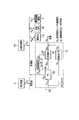
- FIG. 3is a functional block diagram illustrating a main part of the HEMS according to the first embodiment.
- FIG. 4is a diagram for explaining an example of the control target model 300g according to the first embodiment.
- FIG. 5is a flowchart showing a processing procedure in the first embodiment.
- FIG. 6is a conceptual diagram showing an example of gene design of the genetic algorithm according to the first embodiment.
- FIG. 7is a flowchart illustrating an example of the flow of the optimization calculation according to the first embodiment.
- FIG. 8is a diagram for explaining the effects obtained by the first embodiment.
- FIG. 1is a diagram illustrating an example of a system according to the first embodiment.
- FIG. 2is a diagram illustrating an example of the energy management system according to the first embodiment.
- FIG. 3is a functional block diagram illustrating a
- FIG. 9is a diagram illustrating an example of an energy management system according to the second embodiment.
- FIG. 10is a functional block diagram showing the main parts of the cloud computing system 300 and the HEMS according to the second embodiment.
- FIG. 11is a diagram for explaining a control target model 300g according to the second embodiment.
- FIG. 12is a conceptual diagram showing an example of gene design of the genetic algorithm according to the second embodiment.
- FIG. 13is a functional block diagram illustrating the main parts of the cloud computing system 300 and the HEMS according to the third embodiment.
- FIG. 14is a diagram for explaining a control target model 300g according to the third embodiment.
- FIG. 15is a conceptual diagram showing an example of gene design according to the third embodiment.
- FIG. 10is a functional block diagram showing the main parts of the cloud computing system 300 and the HEMS according to the second embodiment.
- FIG. 11is a diagram for explaining a control target model 300g according to the second embodiment.
- FIG. 12is a conceptual diagram showing an example of gene design of the
- FIG. 16is a functional block diagram showing the main parts of the cloud computing system 300 and the HEMS according to the fourth embodiment.
- FIG. 17is a diagram for explaining a control target model 300g according to the fourth embodiment.
- FIG. 18is a diagram for explaining another example of the effect obtained by the embodiment.
- FIG. 19is a diagram for explaining another example of the effect obtained by the embodiment.
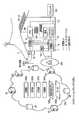
- FIG. 1is a diagram illustrating an example of a system according to the embodiment.
- FIG. 1shows an example of a system known as a so-called smart grid.
- existing gridgrid
- existing power plantssuch as nuclear power, thermal power, and hydropower are connected to a wide variety of consumers such as ordinary households, buildings, and factories through the power grid.
- next generation power systemPower grid
- distributed power sourcessuch as photovoltaic power generation (PV) systems and wind power generators, storage batteries, new transportation systems and charging stations are connected to the power system.
- PVphotovoltaic power generation
- EMSEnergy Management System
- BEMSBuilding Energy Management System
- MEMSMansion Energy Management System
- CEMSCommon Energy Management System
- FEMSFractory Energy Management System
- FIG. 2is a diagram illustrating an example of the energy management system according to the first embodiment.
- the HEMSincludes a client and a cloud computing system (hereinafter abbreviated as “cloud”) 300 as a server system capable of communicating with the client.
- clouda cloud computing system
- the clientis formed with the home gateway (Home Gateway: HGW) 7 installed in the customer's home (home 100) as the core.
- the home gateway 7has a function of communicating with the cloud 300.
- the home gateway 7can receive various services from the cloud 300.
- the home gateway 7can request the cloud computing system 300 for a service for optimizing the energy consumption of the electric equipment provided in the home 100.
- the cloud 300includes a server computer SV and a database DB.
- the server computer SVmay be single or plural.
- the database DBmay be provided in one server computer SV or may be distributed and stored in a plurality of server computers SV.
- electric power (AC voltage) supplied from the electric power system 6is distributed to each home through a power pole transformer 61 and the like, and is sent to a distribution board 20 of the home 100 through an electric energy meter (smart meter) 19. Supplied.
- the watt-hour meter 19has a function of measuring the power generation amount of energy production equipment provided in the home 100, the power consumption of the home 100, the power amount flowing from the power system 6, or the power amount flowing backward to the power system 6. As is well known, the power generated based on the renewable energy is allowed to flow back to the power system 6.
- the distribution board 20supplies electric power to home appliances (lighting, air conditioners, heat pump water heaters (HP), etc.) 5 and a power conditioning system (PCS) 104 connected to the distribution board 20 via a distribution line 21. Supply. Moreover, the distribution board 20 is provided with the measuring device which measures the electric energy for every feeder.
- home applianceslighting, air conditioners, heat pump water heaters (HP), etc.
- PCSpower conditioning system
- the electric deviceis a device that can be connected to the distribution line 21 in the home 100.
- Devices that consume electric power (loads), devices that generate electric power, devices that consume and generate electric power, storage batteries, and the likecorrespond to electric devices. That is, the home appliance 5, the PV system 101, the storage battery 102, the fuel cell (hereinafter referred to as FC unit) 103, and the like all correspond to electrical devices.
- the electric deviceis detachably connected to the distribution line 21 via an outlet (not shown), and is connected to the distribution board 20 via the distribution line 21.
- a solar panelis installed on the roof and outer wall of the home 100 to form a PV system 101.
- the DC voltage generated in the PV system 101is supplied to the PCS 104.
- the PCS 104applies this DC voltage to the storage battery 102 in order to charge the stationary storage battery 102 that is installed at each home 100.
- PV system 101is an energy creation device that produces electric power energy from renewable energy. Wind power generation systems are also in the category of energy creation equipment.
- the FC unit 103is a power generation unit that produces electric power from city gas or LP gas (liquefied propane gas).
- surplus powermay be generated.
- the surplus powercan be charged in the storage battery 102, but the capacity of the storage battery 102 is fixed and cannot be charged unlimitedly beyond the limit.
- surplus poweris converted into heat or the like and discarded, resulting in wasted energy and costs (such as gas charges). In the embodiment, a technique capable of avoiding such a situation will be described.
- the PCS 104includes a converter (not shown), converts AC power from the distribution line 21 to DC power, and supplies it to the storage battery 102. And the electric power sent from the electric power grid
- the PCS 104has a function as a power converter for transferring energy between the storage battery 102 and the FC unit 103 and the distribution line 21.
- the PCS 104also has a function of stably controlling the storage battery 102 and the FC unit 103.
- FIG. 2shows a form in which the PCS 104 is commonly connected to the PV 101, the storage battery 102, and the FC unit 103. Not only this form but PV101, storage battery 102, and FC unit 103 may each be provided with the function of PCS.
- the home 100is provided with a communication line such as a LAN (Local Area Network) to form a home network 25.
- the home gateway 7is detachably connected to both the home network 25 and the IP network 200 via a connector (not shown) or the like. As a result, the home gateway 7 can communicate with electric devices including the watt hour meter 19, the distribution board 20, the PCS 104, and the home appliance 5 connected to the home network 25.
- the home network 25may be a wired line or a wireless line.
- the home gateway 7includes a communication unit 7a as a processing function according to the first embodiment.
- the communication unit 7 atransmits various data to the cloud 300 and receives various data from the cloud 300.
- the home gateway 7is a computer having a Central Processing Unit (CPU) and a memory (not shown).
- the memoryincludes instructions for communicating with the cloud 300, requesting the cloud 300 to calculate an operation plan (operation schedule) related to the operation of the electric device, and reflecting the intention of the customer in the control of the system. Memorize the program.
- the functions of the home gateway 7are realized by the CPU functioning based on various programs.
- the home gateway 7transmits various data to the cloud 300 and receives various data from the cloud 300.
- the home gateway 7is a client that can communicate with the cloud 300 and the server computer SV.
- the various data transmitted from the home gateway 7includes request signals for requesting the cloud 300 to perform various calculations.
- the home gateway 7is connected to the terminal 105 via a wired line or a wireless line.
- the home gateway 7 and the terminal 105can be combined to realize the function as the client.
- the terminal 105may be a so-called touch panel or the like, for example, a general-purpose portable information device, a personal computer, or a tablet terminal.
- the terminal 105displays the operating status and power consumption of the home appliance 5, the PV device 101, the storage battery 102, and the FC unit 103 on, for example, an LCD (Liquid Crystal Display) or informs a consumer (user) by voice guidance or the like.
- the terminal 105includes an operation panel, and accepts various operations and setting inputs by a consumer.
- the IP network 200is the so-called Internet or a system vendor's VPN (Virtual Private Network).
- the home gateway 7can communicate with the server computer SV via the IP network 200 and exchange data with the database DB.
- the IP network 200may include a wireless or wired communication infrastructure for forming a bidirectional communication environment between the home gateway 7 and the cloud 300.
- the cloud 300includes a collection unit 300a, a prediction unit 300b, a calculation unit 300c, and a control unit 300d.
- the database DB of the cloud 300stores a control target model 300g and various data 300h.
- the collection unit 300a, the prediction unit 300b, the calculation unit 300c, and the control unit 300dare functional objects arranged in a single server computer SV or the cloud 300. Those skilled in the art will readily understand how to implement these functional objects in the system.
- the collection unit 300a, the prediction unit 300b, the calculation unit 300c, and the control unit 300dare realized as programs executed by the server computer SV of the cloud 300.
- This programcan be executed by a single computer or can be executed by a system including a plurality of computers.
- Various functions according to the first embodimentare realized by executing instructions described in the program.
- the collection unit 300aacquires various data related to the electrical equipment of the home 100 from the home gateway 7 of each home 100 regularly or irregularly. In addition, the collection unit 300 a acquires user operation history and the like on the terminal 105 from the terminal 105. Note that the collection unit 300a and the terminal 105 can directly communicate with each other via the communication line 40.
- the acquired datais stored as data 300h in the database DB.
- the data 300hincludes the power demand (demand) of each home 100, the power consumption of each home appliance 5, the amount of hot water supply and the operating state of the FC unit 103, the remaining charge and charge / discharge power of the storage battery 102, the power generation of the PV system 101 Including quantity.
- weather dataprovided by the Japan Meteorological Agency can be included in the data 300h. These data are used for prediction of energy demand, etc. as data related to electrical equipment.
- the prediction unit 300bpredicts the energy demand for each hour of each home appliance 5, the energy demand for each hour of the home 100 in total, or the amount of energy production based on the data 300h acquired by the collection unit 300a. That is, the prediction unit 300 predicts the power demand, hot water supply demand, PV power generation amount, etc. of the home 100.
- the calculation unit 300ccalculates an operation plan of the electric device based on the control target model 300g including the storage battery 102 and the FC unit 103 of the home 100, the predicted power demand, the hot water supply demand, and the PV power generation amount. That is, the calculation unit 300c calculates the charge / discharge schedule of the storage battery 102 and the power generation schedule of the FC unit 103 based on the power demand, the hot water supply demand, and the PV power generation amount.
- the calculation unit 300ccalculates an operation plan related to the operation of the electrical equipment that can optimize the energy balance in the home 100 based on the predicted energy demand. This process is called optimal scheduling.
- the energy balanceis, for example, a utility bill, and is an amount that is evaluated based on a balance between the cost of power consumed by the home appliance 5 and the selling price of power generated mainly by the PV system 101.
- the calculated time-series operation plan of the electrical equipmentis stored in the database DB.
- the calculation unit 300ccalculates an operation plan according to a predetermined constraint condition. In the first embodiment, the calculation unit 300c calculates an operation plan based on a condition that the surplus power discarded along with the full charge of the storage battery 102 is minimized.
- the control unit 300dcreates control information for controlling the electrical equipment based on the calculated operation plan. That is, the control unit 300d creates an operation / stop instruction, an output target value, and the like for charging / discharging, operation, or power generation of the FC unit 103 based on the result of optimal scheduling. Such control information is transmitted to the terminal 105 and the home gateway 7 via the communication line 40.
- the terminal 105 of the home 100includes an interface unit (user interface 105a in FIG. 3) for reflecting the intention of the customer in the control of the electric equipment based on the control information transmitted from the control unit 300d.
- the user interface 105 aincludes a display that can display a charge / discharge schedule of the storage battery 102 and a power generation schedule of the FC unit 103. The consumer can check the schedule by looking at the contents displayed on the display, and can select whether to allow or reject the execution of the displayed schedule. Thereby, a consumer's intention can be reflected in execution of a schedule.
- the consumercan input an instruction (command) for requesting recalculation of the schedule to the cloud 300 or giving information necessary for the calculation to the system via the user interface 105a.
- the server computer SVis positioned as a master device
- the home gateway 7is positioned as a slave device that receives a control signal from the master device.
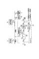
- FIG. 3is a functional block diagram showing the main part of the HEMS according to the first embodiment.
- datasuch as power consumption, operating state, remaining charge and charge / discharge power of the storage battery 102, power demand of the home 100, hot water supply demand, PV power generation amount, etc.
- the datais transmitted to the cloud 300 regularly or irregularly via the home gateway 7.
- ECHONETregistered trademark
- ECHONET Literegistered trademark
- the home gateway 7collects various data via the home network 25 from, for example, an electric device that implements this type of communication function. The collected various data is transmitted to the cloud 300.
- the home gateway 7can collect the power consumption and operating state of the electrical equipment.
- DC devicessuch as the PV system 101, the storage battery 102, and the FC unit 103
- datacan be collected via the PCS 104.
- the home gateway 7transmits the corresponding data to the cloud 300.
- Irregularmeans transmission at such timing.
- the operation history of the customer terminal 105is also transmitted to the cloud 300.
- the prediction unit 300b provided for each consumeruses the power demand, hot water supply demand, PV power generation amount in the collected data, and weather data such as a weather forecast, etc. in addition to the power demand per predetermined time on the target day. , Predict hot water demand and PV power generation. Meteorological data is distributed from other servers (such as the Japan Meteorological Agency) at several times a day. You may perform prediction calculation according to the timing which received this weather data.
- calculation part 300c provided for every consumeris concerned with operation control of an electric equipment based on the energy demand for every predetermined time calculated by prediction calculation, energy supply amount, energy unit price, control object model 300g, etc. Perform optimal scheduling.
- the prediction unit 300b and the calculation unit 300ccan be implemented as functional objects provided exclusively for each customer, for example. That is, the functions of the prediction unit 300b and the calculation unit 300c can be provided for each consumer.
- a formis possible by creating a plurality of threads in the program execution process. According to such a form, there is an advantage such as easy security.
- the prediction unit 300b and the calculation unit 300ccan be implemented as functional objects provided for a plurality of consumers. That is, the calculation by the prediction unit 300b and the calculation unit 300c can be executed in units of a plurality of consumers. According to such a form, it is possible to obtain merits such as saving of calculation resources.
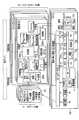
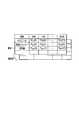
- FIG. 4is a diagram for explaining an example of the control target model 300g according to the first embodiment.
- Control target model 300gincludes each component of power system 6, FC unit 103, storage battery 102, PV system 101, and home appliance 5 (load).
- the FC unit 103includes components of an FC main body 220, an auxiliary boiler 221, a reverse power flow prevention heater 222, and a hot water tank 223.
- the variables in FIG. 4are shown in Table 1.
- the control target model 300gshows an input / output relationship of each component and a relational expression between input variables or output variables between the components.
- the control target model 300gcan be expressed by the following equations (1) to (10).
- the gas supply amount F (t)is shown as the sum of the supply amount F FC (t) to the FC main body 220 and the supply amount F B (t) to the auxiliary boiler.
- the FC main body 220generates power by P FC (t) with respect to the gas supply amount of F FC (t) and exhausts heat by Q FC (t).
- the input / output characteristics of the FC main body 220that is, the relationship between the gas supply amount, the power generation amount, and the exhaust heat amount in the FC main body 220 are approximated as shown in equations (2) and (3).
- the reverse power flow prevention heater 222converts the surplus power P H (t) into heat of the heat quantity Q H (t) and consumes it, thereby controlling the surplus power not to flow back into the power system 6.
- the auxiliary boiler 221supplies hot water supply Q B (t) that cannot be covered by the hot water supply Q ST (t) from the hot water storage tank 223 in the hot water supply demand.
- the hot water storage amount H (t) of the hot water storage tank 223includes the exhaust heat Q FC (t) of the FC main body 220, the heat generation amount Q H (t) of the reverse flow prevention heater 222, and hot water supply as shown in the equation (4). Increase or decrease by Q ST (t).
- the hot water storage efficiency (residual rate) ris a coefficient indicating the ratio of the heat remaining after the reduction due to heat radiation between times t-1 and t.
- the second term on the left-hand sideis the recovered amount of FC exhaust heat, and the third term is the amount of heat generated by the reverse flow prevention heater, both of which are converted into hot water.
- Equation (5)shows the capacity restriction of the hot water tank 223.
- the storage battery 102can be modeled as a model in which the remaining charge S (t) increases or decreases depending on the charge / discharge power P SB (t).
- Formula (6)shows the power supply-demand balance.
- P D (t)indicates the power demand of the home 100
- P C (t)indicates purchased power or sold power
- P PV (t)indicates the amount of power generated by the PV 101.
- Expressions (7) and (8)indicate the constraint condition that the reverse power flow from the FC main body 220 and the storage battery 102 is prohibited.
- Equation (9)shows the constraint condition of the capacity of the storage battery 102.
- Expression (10)shows a constraint condition that the change of the power generation amount with respect to time of the FC unit 103 (FC main body 220) is limited within a predetermined range. That is, the expression (10) indicates that the amount of change in the power generation amount of the FC main body 220 from a certain time t ⁇ 1 to the next time t is the lower limit of the FC power generation decrease rate ⁇ P FC_DOWN and the FC power generation increase rate. It is a constraint condition that it is limited to P FC_UP which is the upper limit of the above.
- the calculation unit 300c(FIGS. 2 and 3), when the power / hot water supply demand, the PV power generation amount, the electricity / gas unit price and the power purchase price are given under the above-described conditions, Each schedule of power generation P FC (t) of the FC unit 103 and charge / discharge P SB (t) of the storage battery 102 is obtained so as to minimize (energy cost). For example, a genetic algorithm can be used as the optimization algorithm. Next, the operation of the above configuration will be described.
- FIG. 5is a flowchart showing a processing procedure in the first embodiment.
- the optimization calculationrequires power demand prediction, hot water supply demand prediction, PV power generation amount prediction, and the like, and this optimization calculation is executed at the timing of several times a day when the prediction calculation is executed.
- the prediction unit 300bacquires the power demand, the hot water supply demand, and the PV power generation amount for each predetermined time from the database DB (step S1-1). In this step, not only current data but also past data such as data on the same day of the previous year may be acquired. Next, the prediction unit 300b predicts a power demand, a hot water supply demand, and a PV power generation amount every predetermined time for calculating an operation plan (step S1-2).
- the calculation unit 300ccalculates a schedule for each predetermined time of the power generation amount of the FC unit 103 and the charge / discharge amount of the storage battery 102 so as to minimize the utility bill (step S1-3).
- the calculated scheduleis stored in the database DB.
- the systemtransmits a message signal indicating the charge / discharge amount schedule of the storage battery or the power generation amount schedule of the FC unit 103 to the terminal 105 via the IP network 200.
- the terminal 105decodes the message signal and displays various schedules on the interface (step S1-4). Routines related to message message transmission and display are executed periodically or in response to a request from the user.
- the cloud 300waits for the arrival of a permission message signal indicating that the execution of the operation plan is permitted by the user (step S1-5). If permitted, the control unit 300d (device operation scheduler) transmits control information for controlling the electric devices of the home 100 to the home gateway 7 of the home 100 via the IP network 200 according to the created schedule. (Step S1-6).
- the control informationincludes, for example, charge / discharge of the storage battery 102, an operation / stop instruction for power generation of the FC unit 103, an output target value, and the like. The above procedure is repeated every time interval of the schedule.
- control unit 300dBased on the result of the optimal scheduling, the control unit 300d creates a charge / discharge of the storage battery 102, an operation / stop instruction for generating power of the FC unit 103, an output target value, and the like for each time interval of the schedule 100. Transmit to home gateway 7. The consumer instructs the system via the user interface 105a whether control is possible based on the transmitted control information.
- FIG. 6is a conceptual diagram showing an example of gene design of the genetic algorithm according to the first embodiment.
- the power generation amount P FC (t) of the FC unit 103 and the charge / discharge power P SB (t) of the storage battery 102are incorporated into the gene.
- An operation plan of the storage battery 102 and the FC unit 103 for one dayis an individual, and a generation is formed from a plurality of individuals.
- Equation (11)shows the fitness Fit to be maximized.
- the operation planis calculated by optimizing this Fit as an objective function.
- Equation (12)represents the utility cost balance C
- equation (13)represents the cost g (P FC , P SB ) required for discontinuity in equipment operation.
- the fitness Fit shown in the equation (11)is a monotonically increasing function f (C) having a utility cost C per day as a variable and a cost g (P FC , P SB ) required for discontinuity in equipment operation> The reciprocal of the sum with zero. If the PV power generation amount greatly exceeds the power demand of the home 100, the utility bill C may be negative. Therefore, in order to correspond to the decrease in the utility bill C and the increase in the fitness Fit, A form is adopted. In the first embodiment, a function satisfying f (C)> 0 is used.
- Power demand, hot water supply demand, PV power generation amount, electricity unit price, gas unit price, and PV purchase priceare given to the above equation, and genetic operations such as mutation, crossing, and dredging are repeated to maximize Fit.
- Such an operationmakes it possible to obtain a series of the power generation amount P FC (t) of the FC unit 103 and the charge / discharge P SB (t) of the storage battery 102 that reduce the utility bill C.
- FIG. 7is a flowchart illustrating an example of the flow of the optimization calculation according to the first embodiment.
- a genetic algorithmis taken as an example of an optimization algorithm. The processing procedure based on the genetic algorithm will be described below.
- Step S2-1Generation of initial population
- the calculation unit 300cgenerates n initial individuals.
- the individual geneincludes, for example, operation / stop of the FC unit 103 at time t, power generation amount of the FC unit 103, charge / discharge power of the storage battery 102, and the like. For example, one day (24 hours) can be provided as a gene string.
- Each individualis a set of gene sequences of the FC unit 103 and the storage battery 102. Solids that do not satisfy the constraint condition are bit-inverted to modify the gene to satisfy the constraint condition.
- Step S2-2The loop of step S2-2 is a process of repeating the processes of steps S2-3 to S2-6. When this loop reaches the specified number of times, the algorithm operation is finished. In addition, the fitness of each individual and the average fitness of the generation are calculated. The average fitness in that generation is compared with the average fitness of the previous two generations. Even if the result of the comparison is equal to or less than the arbitrarily set value ⁇ , the algorithm operation is completed.
- Step S2-3)the calculation unit 300c excludes individuals that do not satisfy the constraint conditions. Therefore, individuals who do not satisfy the constraints are deceived. If there are more than a predetermined number of individuals, individuals with poor fitness (small fitness) are excluded, and the number of individuals is kept below the predetermined number.
- Step S2-4Proliferation In this step, when the number of individuals is smaller than the number of individuals defined in advance, the calculation unit 300c proliferates individuals with the best fitness.
- Crossover Calculation unit 300cperforms pairing at random. Pairing is performed as much as the ratio (crossover rate) to the total number of individuals, and gene loci are randomly selected for each pair and crossed at one point.
- Step S2-6) MutationIn this step, the calculation unit 300c randomly selects individuals by a ratio (mutation rate) with respect to the total number of individuals, and genes at arbitrary (determined randomly) loci of each individual. Invert the bit.
- Step S2-3) to (Step S2-6)is repeated while incrementing the number of generations until the condition of the number of generations ⁇ the maximum number of generations is satisfied (loop of Step S2-2). If this condition is satisfied, the calculation unit 300c outputs the result (step S2-7) and ends the calculation procedure.
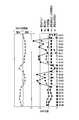
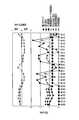
- FIG. 8is a diagram for explaining the effects obtained by the first embodiment.
- FIG. 8shows an example of an operation plan for one day of the storage battery 102 and the FC unit 103 calculated based on prediction results of the daily power demand and hot water supply demand of the home 100.
- the unit price of electricitywas assumed to be 28 yen / kWh from 7:00 to 23:00 and 9 yen / kWh from 23:00 to 7:00 the next day.
- the calculation result using only the electric power demand, the hot water supply demand, the electricity, and the gas unit priceis shown without assuming the improvement of the utility bill due to the power sale.
- the operation plan of the storage battery 102is charged in a time zone where the unit price of electricity is low (from 0:00 to 6:00), and a time zone where the unit price of electricity is high (from 7:00 to 10:00, 13:00 to 22:00) ) To discharge. Thereby, since the purchased electric power in the time zone with a high electricity bill unit price decreases, an electricity bill can be reduced.
- the FC unit 103is operated at the maximum output, and the surplus power generation amount is charged in the storage battery 102 during the time when the power generation amount exceeds the power demand (12:00 to 14:00). Therefore, it is possible to prevent the generated power from being consumed wastefully by the reverse power flow prevention heater 222 and to reduce the gas cost. It can be seen that the reverse power flow prevention heater 222 has moved without operating for 24 hours.
- the PV power generation amount, the power demand, and the hot water supply demand in the home 100are predicted. Then, based on each predicted value, energy management is performed so as to minimize the energy cost (utilization cost) by executing an optimization calculation that minimizes the evaluation function under preset constraint conditions. . That is, the operation plan of the FC unit 103 and the charge / discharge schedule of the storage battery 102 are optimized based on a model in which the power generation amount of the FC unit 103 is variable. Accordingly, it is possible to reduce the utility cost by minimizing the operation of the reverse power flow prevention heater 222.
- the function indicating the fitness Fit to be maximizedincludes the gas charge required for the operation of the FC unit 103.
- a schedule for operating the reverse flow prevention heater 222 in vain under the condition that a possible solution existsis deceived in the process of optimization calculation.
- the amount of change in the power generation amount of the FC unit 103 from a certain time t ⁇ 1 to the next time tis expressed as ⁇ P FC_DOWN (the decrease rate of the power generation amount of the FC unit 103).
- a constraint conditionis set such that it falls within the range of (lower limit value) to P FC_UP (upper limit value of the increase rate of power generation amount of the FC unit 103).
- step S1-2by combining the prediction procedure of step S1-2 and the optimal scheduling of step S1-3 (FIG. 5), it is possible to predict power demand prediction, hot water supply demand prediction, and PV power generation prediction for a period of about one day. Accordingly, supply and demand plans such as FC power generation schedules and storage battery charge / discharge schedules can be created in consideration of the overall balance. Therefore, it is possible to avoid a case where the storage battery 102 is fully charged and the surplus power of the FC unit 103 cannot be charged, or a case where the remaining charge is insufficient when the storage battery 102 should be discharged.
- FIG. 9is a diagram illustrating an example of an energy management system according to the second embodiment.
- An electric vehicle (hereinafter referred to as a vehicle) EVis connected to the distribution line 21 of the home 100.
- the surplus power generated in the home 100can be charged to the storage battery 102 or the in-vehicle battery 106 of the vehicle EV, but cannot be charged beyond the limit.
- a technique capable of avoiding such a situationwill be described.
- the storage capacity of the storage battery 102 installed in the home 100is normally fixed.
- the vehicle-mounted battery 106is the same, and these can be regarded as a fixed capacity storage battery when viewed alone.
- these storage batteriescan be generally understood as storage batteries (storage battery systems) whose capacity changes.
- the capacity of the storage battery systemincreases or decreases depending on whether or not the vehicle EV is connected to the distribution line 21 of the home 100, and also changes depending on the number of the vehicles EV and the performance of the in-vehicle battery 106. In the second embodiment, it is assumed that the capacity of the storage battery system changes as described above.
- the PCS 104is connected to the connector 108 that can be connected to the vehicle EV via the distribution line 21.
- the PCS 104converts AC power from the distribution line 21 into DC power and supplies it to the vehicle EV.
- the PCS 104converts the DC power supplied from the in-vehicle battery 106 into AC power and supplies it to the distribution line 21. Thereby, the vehicle-mounted battery 106 can be charged / discharged via the distribution line 21.
- the data 300hincludes the power demand of each home 100, the power consumption of each household electrical appliance 5, the hot water supply amount and operating state of the FC unit 103, the remaining charge and charge / discharge power of the storage battery 102 and the vehicle battery 106, and the power generation of the PV system 101. Including quantity.
- the calculation unit 300ccharges the storage battery 102 and the in-vehicle battery 106 based on the control target model 300g including the storage battery 102, the in-vehicle battery 106, and the FC unit 103 of the home 100, and the predicted power demand, hot water supply demand, and PV power generation amount.
- the discharge schedule and the power generation schedule of the FC unit 103are calculated.
- the control unit 300dBased on the result of the optimum scheduling by the calculation unit 300c, the control unit 300d creates an operation / stop instruction, an output target value, and the like for charging / discharging, operation, and power generation of the FC unit 103 of the storage battery 102 and the in-vehicle battery 106. .
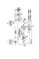
- FIG. 10is a functional block diagram showing the main part of the HEMS according to the second embodiment. 10, parts that are the same as those in FIG. 3 are given the same reference numerals, and only different parts will be described here.
- datasuch as the remaining charge amount and charge / discharge power amount of the in-vehicle battery 106 is transmitted to the cloud 300 regularly or irregularly via the home gateway 7.
- datacan be collected via the PCS 104.
- FIG. 11is a diagram for explaining an example of the control target model 300g according to the second embodiment.
- the control target model 300gincludes each component of the power system 6, the FC unit 103, the storage battery 102, the in-vehicle battery 106, the PV system 101, and the home appliance 5 (load).
- the FC unit 103includes components of an FC main body 220, an auxiliary boiler 221, a reverse power flow prevention heater 222, and a hot water tank 223.
- the variables in FIG. 11are shown in Table 2.
- the control target model 300gshows an input / output relationship of each component and a relational expression between input variables or output variables between the components.
- the control target model 300gcan be expressed by the following equations (14) to (23).
- the storage battery system(storage battery 102, in-vehicle battery 106) can be modeled as a model in which the remaining charge S (t) is increased or decreased by the charge / discharge power P SB (t). Particularly in the second embodiment, as shown in Table 2, the storage battery 102 and the in-vehicle battery 106 are individually modeled.
- Expression (22)represents a constraint condition for the capacity of the storage battery system (the sum of the capacity of the storage battery 102 and the capacity of the in-vehicle battery 106).
- the control unit 300ddisplays the charge / discharge schedule of the storage battery 102, the in-vehicle battery 106, or the operation / stop instruction for power generation of the FC unit 103, the output target value at a predetermined time interval ( For example, it is transmitted to the home gateway 7 of the home 100 every hour).
- the user interface 105adisplays each schedule and various information received from the cloud 300 together with a confirmation message to notify the user. By selecting allow / deny for the confirmation message, the user can select whether or not to execute the calculated schedule. The user can also request the cloud 300 to modify the schedule using the user interface 105a.
- the condition relating to the operation of the vehicle EVis related to Expression (22), and is expressed as, for example, Expression (22) ′.
- Expression (22) ′represents that the remaining charge S (t) of the storage battery system is the sum of the remaining charge S BAT (t) of the storage battery 102 and the remaining charge S EV (t) of the in-vehicle battery 106. Indicates. Furthermore, capacity restrictions are imposed on S BAT (t) and the remaining charge S EV (t), respectively. That is, the condition that the minimum value S BAT_min and the maximum value S BAT_max are not more than S BAT (t) is imposed. The condition that S EV (t) is not less than the minimum value S EV_min and not more than the maximum value S EV_max is imposed.
- S EVshould be at least the remaining charge greater than or equal to the set.
- SEVis a value that is reduced by an amount commensurate with the planned travel distance.
- the calculation unit 300c(FIGS. 9 and 10), when the power / hot water supply demand, the PV power generation amount, the electricity / gas unit price, and the power purchase price are given under the above-described conditions,
- the schedule of the power generation amount P FC (t) of the FC unit 103 that minimizes the balance (energy cost) and the schedule of the charge / discharge amount P SB (t) of the storage battery system (including the storage battery 102 and the in-vehicle battery 106)are calculated.
- a genetic algorithmcan be used as the optimization algorithm.
- each scheduleis calculated, a processing procedure similar to the processing procedure shown in FIG. 5 is executed. Again, each schedule is shown to the user, and after the approval (permission) is obtained, control of the FC unit 103 and the storage battery system is executed.
- FIG. 12is a conceptual diagram showing an example of gene design of the genetic algorithm according to the second embodiment.
- the geneincludes the power generation amount P FC (t) of the FC main body 220 unit 103, the charge / discharge power P SB (t) of the storage battery 102, and the charge / discharge power P EV (t) of the in-vehicle battery 106. Is incorporated.
- the operation plan for one day of the storage battery 102, the in-vehicle battery 106 and the FC unit 103is an individual. A generation is formed by a plurality of individuals.
- Equation (23)shows the fitness Fit to be maximized.
- an operation plancan be calculated as in the first embodiment.
- the utility bill Cis shown in the equation (24)
- the cost g (P FC , P SB ) required for the discontinuity of the equipment operationis shown in the equation (25).
- the Fit in the equation (23)is expressed as the reciprocal of the sum of the monotonically increasing function f (C)> 0 and the cost g (P FC , P SB )> 0 for the same reason as in the first embodiment.
- the Power formula, hot water supply demand, PV power generation amount, electricity unit price, gas unit price, and PV purchase priceare given to each of the formulas (23) to (25), and the maximum Fit is achieved by optimization processing using a genetic algorithm. Is calculated. By such an operation, the power generation balance P FC (t) of the FC unit 103 and the charge / discharge P SB (t) of the storage battery system, that is, P BAT (t) and P EV (t) are minimized. A series to be found is required.
- the optimization calculation that minimizes the evaluation functionis executed under the preset constraint conditions based on the predicted values of the PV power generation amount, the power demand, and the hot water supply demand. Is done.
- a storage battery system including the storage battery 102 and the in-vehicle battery 106is targeted for optimization calculation.
- the operation plan of the FC unit 103, the charging / discharging schedule of the storage battery 102, and the charging / discharging schedule of the in-vehicle battery 106 that can minimize the energy cost (utility cost) in the home 100are calculated. Accordingly, it is possible to reduce the utility cost without wastefully operating the reverse flow prevention heater 222.
- step S1-2the same processing procedure as in FIG. 5 is executed.
- step S1-3the optimal scheduling of step S1-3, the power generation of the FC according to the power demand prediction, hot water supply demand prediction, and PV power generation prediction for a period of about one day.
- An energy supply and demand plansuch as a schedule, a charging / discharging schedule of the storage battery 102, and a charging / discharging schedule of the in-vehicle battery 106 can be created in consideration of the overall balance.
- the second embodimentin addition to the same effects as those obtained in the first embodiment, it is possible to effectively use the vehicle battery. Therefore, it is possible to effectively use surplus power that cannot flow backward to the commercial power system without wasting it.
- FIG. 13is a functional block diagram illustrating a main part of the HEMS according to the third embodiment.
- parts that are the same as those in FIG. 10are given the same reference numerals, and only different parts will be described here.
- FIG. 13shows in-vehicle batteries (reference numerals 106a and 106b) of two vehicles EV.
- EV1 and EV2are reference numerals for distinguishing and indicating the two vehicles EV.
- the calculation unit 300ccalculates the operation schedule of each of the in-vehicle batteries 106a and 106b under comprehensive conditions including the storage battery 102 and other electric devices.
- FIG. 14is a diagram for explaining a control target model 300g according to the third embodiment.
- the remaining charge amount S EV1 (t) of the in-vehicle battery 106a and the remaining charge amount S EV2 (t) of the in-vehicle battery 106bare incorporated in the control target model 300g.
- FIG. 15is a conceptual diagram showing an example of gene design according to the third embodiment.
- the third embodimentas the number of in-vehicle batteries increases compared to the second embodiment, the number of elements characterizing the individual increases. Therefore, the diversity of genes also increases. Therefore, according to the third embodiment, not only can the power supply time during a power failure be increased by increasing the capacity of the storage battery system, but also power can be interchanged between the two vehicles EV during normal times. Therefore, according to the third embodiment, in addition to the effects obtained in the second embodiment, there is an advantage that the flexibility of system operation can be improved.
- FIG. 16is a functional block diagram illustrating a main part of the HEMS according to the fourth embodiment.
- parts that are the same as those in FIG. 13are given the same reference numerals, and only different parts will be described here.
- a gas engine generator (hereinafter referred to as GE) 107 using a prime moveris used as an energy production device.
- FIG. 17is a diagram for explaining a control target model 300g according to the fourth embodiment.
- the FC main body 220is replaced with the generator main body 224, and the FC unit 103 is replaced with the GE unit 107.
- Gas engine generatorsare characterized by better responsiveness than fuel cells. That is, the time from when the power generation command is given until the power is obtained is short. If this feature is utilized, for example, even if the power of the in-vehicle battery 106 is insufficient when suddenly going out in the vehicle EV, the shortage of power can be compensated without greatly affecting the optimum schedule from that point. it can. This is a unique advantage of using a gas engine generator. That is, according to the fourth embodiment, it is possible to construct a system that can flexibly cope with unexpected situations as well as the effects obtained by the first to third embodiments.
- the present inventionis not limited to the above embodiment.
- the use of a genetic algorithmhas been described, but the genetic algorithm is not the only solution for calculating an operation plan. It is possible to calculate an optimal operation plan using various other algorithms.
- a program for executing the energy management method according to the first to fourth embodimentsis stored in a server computer using a storage medium such as a memory card or an optical disk (including a CD-R or a DVD-R). It may be supplied to the SV.
- This type of storage mediumis a computer-readable storage medium that stores a program executed by the computer.
- the programmay be supplied to the server computer SV via a communication line such as the Internet or wireless communication.
- the operation plan of the electric deviceis not limited to the graph shown in FIG. 8, and various patterns of graphs can be calculated.
- 18 and 19are graphs showing other examples of the operation pattern of the electric device. These figures show examples of graphs calculated in consideration of the presence of the vehicle EV and the availability of the in-vehicle battery. That is, the charge / discharge amount of the in-vehicle battery, the purchased electric energy in consideration of the capacity of the in-vehicle battery, and the like are calculated.
- FIG. 18is a graph created assuming that the vehicle EV stayed at home all day. That is, this graph was created on the assumption that the in-vehicle battery was connected to the distribution line 21 all day.
- poweris supplied from the storage battery 102 in the morning (7:00 to 11:00), and from evening to night (17:00 to 22). : 00), it can be seen that power is supplied from the in-vehicle battery 106. It can also be seen that the storage battery 102 and the in-vehicle battery 106 are charged from midnight to dawn (22:00 to 5:00).
- FIG. 19is a graph created on the assumption that the vehicle EV has gone out during the day. That is, this graph was created on the assumption that the in-vehicle battery was detached from the distribution line 21.
- the home appliance 5has to rely on the power of the storage battery 102 to operate.
- the operation planis immediately recalculated. Further, according to the graph of FIG. 19, it can be seen that the in-vehicle battery 106 is charged at night (22:00 to 6:00).
Landscapes
- Engineering & Computer Science (AREA)
- Power Engineering (AREA)
- Business, Economics & Management (AREA)
- Transportation (AREA)
- Mechanical Engineering (AREA)
- Economics (AREA)
- Health & Medical Sciences (AREA)
- Marketing (AREA)
- Theoretical Computer Science (AREA)
- Human Resources & Organizations (AREA)
- Strategic Management (AREA)
- Tourism & Hospitality (AREA)
- Physics & Mathematics (AREA)
- General Business, Economics & Management (AREA)
- General Physics & Mathematics (AREA)
- Water Supply & Treatment (AREA)
- General Health & Medical Sciences (AREA)
- Public Health (AREA)
- Primary Health Care (AREA)
- Entrepreneurship & Innovation (AREA)
- Operations Research (AREA)
- Quality & Reliability (AREA)
- Computer Networks & Wireless Communication (AREA)
- Supply And Distribution Of Alternating Current (AREA)
- Management, Administration, Business Operations System, And Electronic Commerce (AREA)
Abstract
Description
Translated fromJapanese本発明の実施形態は、エネルギーを管理する技術に関する。Embodiment of this invention is related with the technique which manages energy.
近年の環境保全意識の高まりと電力不足への不安を背景として、太陽光発電(Photovoltaic Power Generation:PV)システム、蓄電池、あるいは燃料電池(Fuel Cell:FC)ユニットなどの分散型電源や、家庭エネルギー管理システム(Home Energy Management System:HEMS)に注目が集まっている。また、ゼロエネルギー住宅(Zero Energy Home:ZEH)、あるいはネット・ゼロエネルギー住宅も注目されている。ネット・ゼロエネルギー住宅は、年間の一次エネルギー消費量が正味(net)で概ねゼロとなる住宅を意味する。Distributed power sources such as photovoltaic (Photovoltaic シ ス テ ム Power Generation: PV) systems, storage batteries, or fuel cell (FC) units, and household energy, against the backdrop of rising awareness of environmental conservation and concerns over power shortages in recent years Attention has been focused on the management system (Home Energy Management System: HEMS). Also, zero energy homes (ZEH) or net zero energy homes are attracting attention. A net zero energy house means a house where annual primary energy consumption is almost zero in net.
燃料電池は、昼夜、天候を問わず安定して発電でき、排熱を利用して熱エネルギーを供給できるので、分散電源のなかでも特に有望視されている。しかしながら燃料電池から商用電力系統(grid)への逆潮流(reverse flow)は、電力会社との契約上、許されていない。そこで、燃料電池により発電された電力の逆潮流を防止するための技術が幾つか提案されている。Fuel cells are particularly promising among distributed power sources because they can generate power stably, day or night, regardless of the weather, and can supply thermal energy using exhaust heat. However, a reverse flow from the fuel cell to the commercial power grid is not permitted under contracts with the power company. In view of this, several techniques have been proposed for preventing reverse power flow of the power generated by the fuel cell.
電気自動車(Electric Vehicle)に関する技術開発も盛んである。この種の車両に搭載されるバッテリーは旧来のものに比べて著しく進歩しており、その性能を生かして、例えば停電時などにその電力を家庭に供給することが考えられている。Technological development related to electric vehicles (electric vehicles) is also thriving. The battery mounted on this type of vehicle has made significant progress compared to the conventional one, and it is considered that the power is supplied to the home at the time of a power failure, for example, by taking advantage of its performance.
燃料電池から生じた余剰電力をダミー負荷や逆潮流防止ヒータで消費させて逆潮流を防止する、という技術がある。これではエネルギーが無駄に消費される。余剰電力を蓄電池に充電するという技術もあるが、充電の必要が生じたときに既に満充電であり、充電できないことも考えられる。There is a technology to prevent reverse power flow by consuming surplus power generated from a fuel cell with a dummy load or a reverse power flow prevention heater. This wastes energy. There is also a technique for charging the storage battery with surplus power, but it may be considered that the battery is already fully charged when it needs to be charged and cannot be charged.
逆潮流防止ヒータと蓄電池とを併用しても、燃料電池の出力を変化させるには長い時間を要するので、電力需要(デマンド)の少ない時間が長期に渡ると、余剰電力の発生量が蓄電池容量を上回ってしまう。このようなケースでは燃料電池の運転を停止するか、逆潮流防止ヒータで余剰電力を消費せざるを得ない。リレーなどで燃料電池をグリッドから分離して逆潮流を防止することはできても、余剰電力は無駄に消費されているのが現状である。Even if a reverse power flow prevention heater and a storage battery are used together, it takes a long time to change the output of the fuel cell. Therefore, if the amount of power demand (demand) is long, the amount of surplus power generated will be the storage battery capacity. Will be exceeded. In such a case, the operation of the fuel cell must be stopped, or surplus power must be consumed by the reverse flow prevention heater. Even though the fuel cell can be separated from the grid by a relay or the like to prevent reverse power flow, the surplus power is consumed in vain.
一方、電気自動車の車載バッテリーとHEMSとを組み合わせた技術は未だ発展の途上にある。特に、家庭内の電気機器と車載バッテリーとを総合的に考慮したエネルギー管理の手法が要望されている。On the other hand, the technology combining electric vehicle battery and HEMS is still under development. In particular, there is a demand for an energy management method that comprehensively considers household electrical devices and in-vehicle batteries.
目的は、エネルギーの有効活用を図り得るエネルギー管理システム、サーバ、エネルギー管理方法および記憶媒体を提供することにある。The purpose is to provide an energy management system, a server, an energy management method, and a storage medium that can effectively use energy.
実施形態によれば、エネルギー管理システムは、クライアントと、クライアントと通信可能なサーバとを具備する。サーバは取得部、予測部、計算部、制御部を備える。取得部は、蓄電池を含む建物の電気機器に係わるデータをクライアントから取得する。予測部は、建物におけるエネルギーデマンドおよびエネルギー生産量を、データに基づいて予測する。計算部は、蓄電池の満充電に伴い破棄される余剰電力を最小化する条件下で、建物におけるエネルギー収支を最適化すべく、エネルギーデマンドおよびエネルギー生産量に基づいて電気機器の運転計画を計算する。制御部は、計算された運転計画に基づいて、電気機器を制御するための制御情報を作成する。According to the embodiment, the energy management system includes a client and a server capable of communicating with the client. The server includes an acquisition unit, a prediction unit, a calculation unit, and a control unit. An acquisition part acquires the data regarding the electrical equipment of a building containing a storage battery from a client. The prediction unit predicts the energy demand and energy production amount in the building based on the data. A calculation part calculates the operation plan of an electric equipment based on an energy demand and energy production amount in order to optimize the energy balance in a building on the conditions which minimize the surplus electric power discarded with the full charge of a storage battery. The control unit creates control information for controlling the electric device based on the calculated operation plan.
図1は、実施形態に係わるシステムの一例を示す図である。図1は、いわゆるスマートグリッドとして知られるシステムの一例を示す。既存の電力網(grid)では原子力、火力、水力などの既存発電所と、一般家庭や、ビル、工場といった多種多様な需要家とが電力網によって接続される。次世代の電力系統(Power grid)ではこれらに加えて太陽光発電(Photovoltaic Power Generation:PV)システムや風力発電装置などの分散型電源や蓄電池、新交通システムや充電スタンドなどが電力系統に接続される。これら多種多様な要素は通信グリッドを介して通信することが可能である。FIG. 1 is a diagram illustrating an example of a system according to the embodiment. FIG. 1 shows an example of a system known as a so-called smart grid. In the existing grid (grid), existing power plants such as nuclear power, thermal power, and hydropower are connected to a wide variety of consumers such as ordinary households, buildings, and factories through the power grid. In addition to these, in the next generation power system (Power grid), distributed power sources such as photovoltaic power generation (PV) systems and wind power generators, storage batteries, new transportation systems and charging stations are connected to the power system. The These various elements can communicate via a communication grid.
エネルギーを管理するシステムは、エネルギーマネジメントシステム(Energy Management System:EMS)と総称される。EMSはその規模などに応じて幾つかに分類される。例えば、一般家庭向けのHEMSのほか、ビルディング向けのBEMS(Building Energy Management System)や集合住宅向けのMEMS(Mansion Energy Management System)がある。さらに、コミュニティ向けのCEMS(Community Energy Management System)、工場向けのFEMS(Factory Energy Management System)などがある。これらのシステムが連携することできめ細かなエネルギー最適化制御が実現される。∙ Energy management systems are collectively referred to as Energy Management System (EMS). EMS is classified into several types according to its size. For example, in addition to HEMS for general households, there are BEMS (Building Energy Management System) for buildings and MEMS (Mansion Energy Management System) for apartments. Furthermore, there are CEMS (Community Energy Management System) for communities and FEMS (Factory Energy Management System) for factories. Fine energy optimization control can be realized by linking these systems.
これらのシステムによれば既存の発電所、分散型電源、太陽光や風力などの再生可能エネルギー源、および需要家の相互間で高度な協調運用が可能になる。これにより自然エネルギーを主体とするエネルギー供給システムや、需要家と事業者との双方向連携による需要家参加型のエネルギー需給といった、新規かつスマートな形態の電力供給サービスが生み出される。These systems enable highly coordinated operation among existing power plants, distributed power sources, renewable energy sources such as solar and wind power, and consumers. As a result, a new and smart power supply service such as an energy supply system mainly composed of natural energy and a consumer-participation type energy supply and demand through two-way cooperation between a customer and a business operator is created.
[第1の実施形態]
図2は、第1の実施形態に係るエネルギー管理システムの一例を示す図である。HEMSは、クライアントと、クライアントと通信可能なサーバシステムとしてのクラウドコンピューティングシステム(以下、クラウドと略称する)300とを備える。[First Embodiment]
FIG. 2 is a diagram illustrating an example of the energy management system according to the first embodiment. The HEMS includes a client and a cloud computing system (hereinafter abbreviated as “cloud”) 300 as a server system capable of communicating with the client.
クライアントは、需要家宅(ホーム100)に設置されるホームゲートウェイ(Home Gateway:HGW)7を中核として形成される。ホームゲートウェイ7はクラウド300と通信する機能を備える。ホームゲートウェイ7は、クラウド300から各種のサービスの提供を受けることができる。例えばホームゲートウェイ7は、ホーム100に備わる電気機器のエネルギー消費を最適化するためのサービスを、クラウドコンピューティングシステム300に要求することが可能である。The client is formed with the home gateway (Home Gateway: HGW) 7 installed in the customer's home (home 100) as the core. The
クラウド300は、サーバコンピュータSVとデータベースDBとを備える。サーバコンピュータSVは単体でも複数でも良い。データベースDBは一つのサーバコンピュータSVに備えられても、複数のサーバコンピュータSVに分散して記憶されてもよい。The
図2において、電力系統6から供給される電力(交流電圧)は、電柱の変圧器61などを経て各家庭に分配され、電力量計(スマートメータ)19を経てホーム100の分電盤20に供給される。電力量計19は、ホーム100に備わるエネルギー生産機器の発電量、ホーム100の電力消費量、電力系統6から流れ込む電力量、あるいは電力系統6に逆潮流する電力量などを計測する機能を備える。周知のように、再生可能エネルギーに基づいて発電された電力は、電力系統6に逆潮流することを許される。In FIG. 2, electric power (AC voltage) supplied from the
分電盤20は配電線21を介して、この分電盤20に接続される家電機器(照明、エアコン、あるいはヒートポンプ式給湯器(HP)など)5やパワーコンディショニングシステム(PCS)104に電力を供給する。また分電盤20は、フィーダごとの電力量を計測する計測装置を備える。The
ホーム100は、電気機器を備える。電気機器はホーム100内の配電線21に接続可能な機器である。電力を消費する機器(負荷)、電力を生成する機器、電力を消費し生成する機器、および蓄電池などが電気機器に該当する。つまり家電機器5、PVシステム101、蓄電池102および燃料電池(以下、FCユニットと表記する)103などが、いずれも電気機器に相当する。電気機器はコンセント(図示せず)を介して配電線21に着脱可能に接続され、配電線21を介して分電盤20に接続される。
ホーム100の屋根や外壁には太陽光パネルが設置されPVシステム101が形成される。PVシステム101で発生した直流電圧はPCS104に供給される。PCS104はホーム100ごとに据え置かれる、据置型の蓄電池102を充電すべく、この直流電圧を蓄電池102に与える。A solar panel is installed on the roof and outer wall of the
PVシステム101は、再生可能エネルギーから電力エネルギーを生産する創エネルギー機器である。風力発電システムなども創エネルギー機器の範疇に入る。これに対しFCユニット103は都市ガスやLPガス(液化プロパンガス)から電力を生産する発電ユニットである。
FCユニット103により生成された電力は電力系統6に逆潮流することを禁止されているので、余剰電力を生じることがある。余剰電力は蓄電池102に充電されることが可能であるが、蓄電池102の容量は固定的であり、限度を超えて無制限に充電することはできない。蓄電池102が満充電になると余剰電力は熱などに変換されて破棄されるので、エネルギーやコスト(ガス料金など)に無駄を生じる。実施形態ではこのような事態を回避可能とする技術について説明する。Since the power generated by the
PCS104はコンバータ(図示せず)を備え、配電線21からの交流電力を直流電力に変換して蓄電池102に供給する。そして、電力系統6から送られる電力を深夜においても蓄電池102に充電することができる。さらにPCS104はインバータ(図示せず)を備え、蓄電池102あるいはFCユニット103から供給される直流電力を交流電力に変換して配電線21に供給する。これにより、家電機器5はPCS104を介して、蓄電池102やFCユニット103からも電力の供給を受けることができる。The
要するにPCS104は、蓄電池102およびFCユニット103と配電線21との間でエネルギーを授受するための、電力変換器としての機能を備える。PCS104は蓄電池102やFCユニット103を安定に制御する機能も備える。なお図2において、PCS104がPV101、蓄電池102およびFCユニット103に共通に接続される形態が示される。この形態に限らず、PV101、蓄電池102およびFCユニット103がそれぞれ個々にPCSの機能を備えてもよい。In short, the
ホーム100にはLAN(Local Area Network)などの通信回線が配設され、ホームネットワーク25が形成される。ホームゲートウェイ7はホームネットワーク25とIPネットワーク200との双方に、コネクタ(図示せず)などを介して着脱可能に接続される。これによりホームゲートウェイ7は、ホームネットワーク25に接続される電力量計19、分電盤20、PCS104、および家電機器5を含む電気機器と相互に通信可能である。なおホームネットワーク25は有線回線、あるいは無線回線のいずれでも良い。The
ホームゲートウェイ7は、第1の実施形態に係る処理機能として通信部7aを備える。通信部7aは、クラウド300に各種のデータを送信し、またクラウド300から各種のデータを受信する。The
ホームゲートウェイ7はCentral Processing Unit(CPU)とメモリ(図示せず)を備えるコンピュータである。メモリは、クラウド300と通信したり、電気機器の動作に係わる運転計画(運転スケジュール)の計算をクラウド300に要求したり、システムの制御に需要家の意思を反映させたりするための命令を含むプログラムを記憶する。CPUが各種のプログラムに基づいて機能することで、ホームゲートウェイ7に係る諸機能が実現される。The
すなわちホームゲートウェイ7は、クラウド300に各種のデータを送信し、またクラウド300から各種のデータを受信する。ホームゲートウェイ7は、クラウド300、サーバコンピュータSVと通信可能なクライアントである。ホームゲートウェイ7から送信される各種データには、クラウド300に各種の演算を要求するための要求信号が含まれる。That is, the
ホームゲートウェイ7は有線回線または無線回線を介して端末105に接続される。ホームゲートウェイ7と端末105とを合わせて上記クライアントとしての機能を実現することも可能である。端末105はいわゆるタッチパネルなどのほか、例えば汎用的な携帯情報機器やパーソナルコンピュータ、あるいはタブレット端末などでもよい。The
端末105は家電機器5、PV装置101、蓄電池102、FCユニット103の稼働状況や電力消費量を例えばLCD(Liquid Crystal Display)に表示したり、音声ガイダンスなどで需要家(ユーザ)に報知する。また端末105は操作パネルを備え、需要家による各種の操作や設定入力を受け付ける。The terminal 105 displays the operating status and power consumption of the
IPネットワーク200は、いわゆるインターネット、あるいはシステムベンダのVPN(Virtual Private Network)などである。ホームゲートウェイ7は、IPネットワーク200を経由してサーバコンピュータSVと通信したり、データベースDBとデータを授受したりできる。なおIPネットワーク200は、ホームゲートウェイ7とクラウド300との間に双方向の通信環境を形成するための、無線または有線の通信インフラストラクチャを含んで良い。The
クラウド300は、収集部300a、予測部300b、計算部300c、および制御部300dを備える。クラウド300のデータベースDBは、制御対象モデル300g、および各種のデータ300hを記憶する。収集部300a、予測部300b、計算部300c、および制御部300dは、単体のサーバコンピュータSV、あるいは、クラウド300に配置される機能オブジェクトである。これらの機能オブジェクトを如何にしてシステムにインプリメントするかは、当業者によれば容易に理解されるであろう。The
例えば収集部300a、予測部300b、計算部300c、および制御部300dは、クラウド300のサーバコンピュータSVにより実行されるプログラムとして実現される。このプログラムは単体のコンピュータにより実行されることもできるし、複数のコンピュータを備えるシステムにより実行されることも可能である。プログラムに記載される命令が実行されることで、第1の実施形態に係わる諸機能が実現される。For example, the
収集部300aは、ホーム100の電気機器に係わる各種データを各ホーム100のホームゲートウェイ7から定期的、あるいは不定期に取得する。また収集部300aは、端末105におけるユーザの操作履歴などを端末105から取得する。なお収集部300aと端末105とが通信回線40を介して直接通信することも可能である。The
取得されたデータはデータベースDBにデータ300hとして保持される。データ300hは、各ホーム100の電力デマンド(デマンド)、家電機器5のそれぞれの電力消費量、FCユニット103の給湯量や稼動状態、蓄電池102の充電残量や充放電電力、PVシステム101の発電量などを含む。加えて、気象庁などから提供される気象データなどもデータ300hに含めることが可能である。これらのデータは電気機器に係わるデータとしてエネルギーデマンドの予測などに利用される。The acquired data is stored as data 300h in the database DB. The data 300h includes the power demand (demand) of each
予測部300bは、収集部300aにより取得されたデータ300hに基づいて、各家電機器5の時間ごとのエネルギーデマンド、ホーム100のトータルでの時間ごとのエネルギーデマンド、あるいはエネルギー生産量などを予測する。すなわち予測部300は、ホーム100の電力デマンド、給湯デマンド、PV発電量などを予測する。The
計算部300cは、ホーム100の蓄電池102およびFCユニット103を含む制御対象モデル300gと、予測した電力デマンド、給湯デマンド、およびPV発電量に基づいて、電気機器の運転計画を計算する。つまり計算部300cは、電力デマンド、給湯デマンド、およびPV発電量に基づいて蓄電池102の充放電スケジュール、およびFCユニット103の発電スケジュールを計算する。The
つまり計算部300cは、予測されたエネルギーデマンドに基づいてホーム100におけるエネルギー収支を最適化可能な、電気機器の動作に係わる運転計画を計算する。この処理を最適スケジューリングと称する。That is, the
エネルギー収支とは例えば光熱費収支であり、家電機器5により消費される電力のコストと、主にPVシステム101により生成される電力の売電料金とのバランスにより評価される量である。計算された電気機器の時系列の運転計画はデータベースDBに記憶される。
さらに計算部300cは、既定の制約条件に従って運転計画を算出する。この第1の実施形態では、計算部300cは、蓄電池102の満充電に伴い破棄される余剰電力を最小化する、という条件に基づいて運転計画を算出する。The energy balance is, for example, a utility bill, and is an amount that is evaluated based on a balance between the cost of power consumed by the
Furthermore, the
制御部300dは、計算された運転計画に基づいて電気機器を制御するための制御情報を作成する。すなわち制御部300dは、最適スケジューリングの結果に基づいて、蓄電池102の充放電、稼動、またはFCユニット103の発電のための運転・停止指示、出力目標値などを作成する。これらの制御情報は、通信回線40を介して端末105やホームゲートウェイ7に送信される。The
ホーム100の端末105は、制御部300dから送信された制御情報に基づく電気機器の制御に需要家の意思を反映させるための、インタフェース部(図3のユーザインタフェース105a)を備える。ユーザインタフェース105aは、蓄電池102の充放電スケジュールやFCユニット103の発電スケジュールを表示可能な、表示器を備える。需要家は表示器に表示された内容を見てスケジュールを確認したり、表示されたスケジュールの実行の許可または拒否を選択したりすることができる。これによりスケジュールの実行に需要家の意思を反映させることができる。The
また、需要家は、クラウド300にスケジュールの再計算を要求したり、そのために必要になる情報をシステムに与えたりするための指示(コマンド)を、ユーザインタフェース105aを介して入力することができる。以上の構成において、サーバコンピュータSVは主装置としての位置付けにあり、ホームゲートウェイ7は主装置からの制御信号を受信する従装置としての位置付けにあると理解することが可能である。Further, the consumer can input an instruction (command) for requesting recalculation of the schedule to the
図3は、第1の実施形態に係るHEMSの要部を示す機能ブロック図である。図3において、ホーム100の家電機器5の所定時間ごとの電力消費量、稼動状態、蓄電池102の充電残量や充放電電力量、ホーム100の電力デマンド、給湯デマンド、PV発電量などのデータが、ホームゲートウェイ7を介して定期的、あるいは不定期にクラウド300に送信される。FIG. 3 is a functional block diagram showing the main part of the HEMS according to the first embodiment. In FIG. 3, data such as power consumption, operating state, remaining charge and charge / discharge power of the
ECHONET(登録商標)やECHONET Lite(登録商標)などが、ホーム100における宅内通信プロトコルとして知られている。ホームゲートウェイ7は、例えばこの種の通信機能を実装する電気機器から、ホームネットワーク25を介して各種データを収集する。収集された各種データはクラウド300に送信される。ECHONET (registered trademark), ECHONET Lite (registered trademark), and the like are known as home communication protocols in the
分電盤20に通信機能を備える計測装置を設置することにより、ホームゲートウェイ7は、電気機器の消費電力や稼働状態を収集することが可能である。PVシステム101、蓄電池102、FCユニット103などの直流機器については、PCS104を介してデータを収集することも可能である。By installing a measuring device having a communication function on the
需要家によりユーザインタフェース105aを介して設定された各デマンド・発電量に係る変動所定量に対して現実のデータが上回る状態、あるいは下回る状態になると、ホームゲートウェイ7は該当データをクラウド300に送信する。不定期とはこのようなタイミングでの送信を意味する。また需要家の端末105の操作履歴なども、クラウド300に送信される。これらのデータや情報はデータベースDB群に格納される。When the actual data exceeds or falls below the predetermined fluctuation amount related to each demand / power generation amount set by the consumer via the user interface 105a, the
需要家ごとに設けられる予測部300bは、収集したデータのうち電力デマンド、給湯デマンド、PV発電量に加えて天気予報などの気象データなども用いて、対象とする日の所定時間ごとの電力デマンド、給湯デマンド、PV発電量を予測する。気象データは1日数回のタイミングで他のサーバ(気象庁など)から配信される。この気象データを受信したタイミングに合わせて予測計算を実行してもよい。The
そして、需要家ごとに設けられる計算部300cは、予測計算により算出された所定時間ごとのエネルギーデマンド、エネルギー供給量、エネルギー単価、および制御対象モデル300gなどに基づいて、電気機器の動作制御に係わる最適スケジューリングを実行する。And the
予測部300b、計算部300cは、例えば需要家ごとに専用に設けられる機能オブジェクトとしてインプリメントされることが可能である。つまり予測部300b、計算部300cの機能を需要家ごとに設けることが可能である。例えばプログラムの実行過程においてスレッドを複数立てることで、このような形態が可能である。このような形態によればセキュリティを確保し易いなどのメリットがある。The
あるいは、予測部300b、計算部300cを、複数の需要家に対して設けられる機能オブジェクトとしてインプリメントすることも可能である。つまり予測部300b、計算部300cによる演算を、複数の需要家をまとめた単位で実行することも可能である。このような形態によれば計算リソースの節約などのメリットを得ることが可能である。Alternatively, the
図4は、第1の実施形態に係る制御対象モデル300gの一例について説明するための図である。制御対象モデル300gは、電力系統6、FCユニット103、蓄電池102、PVシステム101、および家電機器5(負荷)の各構成要素を含む。FCユニット103は、FC本体220、補助ボイラ221、逆潮流防止ヒータ222、および貯湯槽223の各構成要素を含む。図4における変量は表1に示される。
制御対象モデル300gは、それぞれの構成要素の入出力関係と、構成要素間の入力変数、あるいは出力変数の間の関係式を示す。例えば次式(1)~(10)により制御対象モデル300gを表現することが可能である。
式(1)において、ガス供給量F(t)は、FC本体220への供給量FFC(t)と補助ボイラへの供給量FB(t)との和として示される。FC本体220は、FFC(t)のガス供給量に対してPFC(t)だけ発電し、QFC(t)だけ排熱するとする。このFC本体220の入出力特性、すなわちFC本体220におけるガス供給量、発電量、および排熱量の関係を、式(2)、(3)のように近似して示す。In the equation (1), the gas supply amount F (t) is shown as the sum of the supply amount FFC (t) to the FC
逆潮流防止ヒータ222は、余剰電力PH(t)を熱量QH(t)の熱に変換にして消費させることで、余剰電力が電力系統6に逆潮流しないように制御する。補助ボイラ221は、給湯デマンドのうち貯湯槽223からの給湯QST(t)で賄いきれない分の給湯QB(t)を供給する。The reverse power
貯湯槽223の貯湯量H(t)は、式(4)に示されるように、FC本体220の排熱QFC(t)、逆潮流防止ヒータ222の発熱量QH(t)、および給湯QST(t)により増減する。
式(4)の左辺は貯湯槽223に入る熱量を湯量ベースで表すもので、左辺第1項はr・H(t-1)=残存率×前回貯湯量=放熱後に残る湯量である。ここで貯湯効率(残存率)rは、時間t-1からtの間で、放熱による減少後に残る熱の割合を示す係数である。左辺第2項はFC排熱の回収量であり、第3項は逆潮流防止ヒータの発熱量であり、いずれも湯量換算値である。The hot water storage amount H (t) of the hot
The left side of Equation (4) represents the amount of heat entering the hot
式(5)は貯湯槽223の容量制約を示す。蓄電池102は、充放電電力PSB(t)により充電残量S(t)が増減するモデルとしてモデル化されることが可能である。Equation (5) shows the capacity restriction of the
式(6)は、電力の需給バランスを示す。PD(t)はホーム100の電力デマンドを示し、PC(t)は購入電力または売電電力を示し、PPV(t)はPV101の発電量を示す。式(7)、(8)はFC本体220と蓄電池102からの逆潮流を禁止するという制約条件を示す。式(9)は蓄電池102の容量の制約条件を示す。Formula (6) shows the power supply-demand balance. PD (t) indicates the power demand of the
式(10)は、FCユニット103(FC本体220)の、発電量の時間に対する変化を既定の範囲内に制限するという制約条件を示す。つまり式(10)は、或る時刻t-1から次の時刻tにおけるFC本体220の発電量の変化量を、FC発電量の減少速度の下限である-PFC_DOWNとFC発電量の増加速度の上限であるPFC_UPとの間に制限するという制約条件である。Expression (10) shows a constraint condition that the change of the power generation amount with respect to time of the FC unit 103 (FC main body 220) is limited within a predetermined range. That is, the expression (10) indicates that the amount of change in the power generation amount of the FC
計算部300c(図2、図3)は、以上のような条件のもとで、電力・給湯デマンドとPV発電量、電気・ガスの料金単価および電力買い取り価格が与えられたとき、光熱費収支(エネルギーコスト)を最小にするようにFCユニット103の発電PFC(t)、蓄電池102の充放電PSB(t)の各スケジュールを求める。最適化アルゴリズムには例えば遺伝的アルゴリズムを用いることができる。次に、上記構成における作用を説明する。The
図5は、第1の実施形態における処理手順を示すフローチャートである。最適化演算には電力デマンド予測、給湯デマンド予測、PV発電量予測などが必要であり、この最適化演算は予測計算が実行される1日数回のタイミングに合わせて実行される。FIG. 5 is a flowchart showing a processing procedure in the first embodiment. The optimization calculation requires power demand prediction, hot water supply demand prediction, PV power generation amount prediction, and the like, and this optimization calculation is executed at the timing of several times a day when the prediction calculation is executed.
図5において、予測部300bは所定時間ごとの電力デマンド、給湯デマンド、PV発電量をデータベースDBから取得する(ステップS1-1)。このステップでは現在のデータだけでなく、例えば前年同日のデータなど過去のデータを取得しても良い。次に予測部300bは、運転計画算出のため所定時間ごとの電力デマンド、給湯デマンド、PV発電量を予測する(ステップS1-2)。In FIG. 5, the
次に計算部300cは、光熱費収支を最小とすべくFCユニット103の発電量と蓄電池102の充放電量の所定時間ごとのスケジュールを算出する(ステップS1-3)。算出されたスケジュールはデータベースDBに記憶される。Next, the
次にシステムは、蓄電池の充放電量スケジュールまたはFCユニット103の発電量のスケジュールを示すメッセージ信号を、IPネットワーク200を介して端末105に送信する。端末105はメッセージ信号を解読して各種スケジュールをインタフェースに表示する(ステップS1-4)。メッセージ信号の送信から表示に係わるルーチンは定期的に、あるいはユーザからの要求に応じて実行される。Next, the system transmits a message signal indicating the charge / discharge amount schedule of the storage battery or the power generation amount schedule of the
次に、クラウド300は、運転計画の実行がユーザにより許可されたことを示す許可メッセージ信号の到来を待ち受ける(ステップS1-5)。許可されれば、制御部300d(機器運転スケジューラ)は、作成されたスケジュールに沿ってホーム100の電気機器を制御するための制御情報を、IPネットワーク200経由でホーム100のホームゲートウェイ7に送信する(ステップS1-6)。制御情報は、例えば蓄電池102の充放電、FCユニット103の発電のための運転・停止指示、出力目標値などを含む。以上の手順はスケジュールの時間間隔ごとに繰り返される。Next, the
制御部300dは、最適スケジューリングの結果に基づいて、蓄電池102の充放電、またはFCユニット103の発電のための運転・停止指示、出力目標値などをスケジュールの時間間隔ごとに作成し、ホーム100のホームゲートウェイ7に送信する。需要家は送信された制御情報に基づく制御の可否を、ユーザインタフェース105aを介してシステムに指示する。Based on the result of the optimal scheduling, the
図6は、第1の実施形態に係る遺伝的アルゴリズムの遺伝子設計の一例を示す概念図である。第1の実施形態では、遺伝子にFCユニット103の発電量PFC(t)と蓄電池102の充放電電力PSB(t)とが組み込まれる。1日分の蓄電池102およびFCユニット103の運転計画を個体とし、世代は複数の個体から形成される。FIG. 6 is a conceptual diagram showing an example of gene design of the genetic algorithm according to the first embodiment. In the first embodiment, the power generation amount PFC (t) of the
式(11)は、最大化すべき適合度Fitを示す。このFitを目的関数として最適化することにより運転計画が算出される。式(12)は光熱費収支Cを示し、式(13)は機器稼動の不連続性に掛かるコストg(PFC、PSB)を示す。光熱費収支Cにおけるt=0~t=23までの総和は、24時間にわたっての和を求めることに相当する。 
式(11)に示される適合度Fitは、1日あたりの光熱費収支Cを変数とする単調増加関数f(C)と機器稼動の不連続性に掛かるコストg(PFC,PSB)>0との和の、逆数である。PV発電量がホーム100の電力デマンドを大きく上回ると光熱費収支Cが負になることがあるので、光熱費収支Cの減少と適合度Fitの増加とを対応させるために、式(11)のフォームが採用される。第1の実施形態ではf(C)>0となる関数が用いられる。The fitness Fit shown in the equation (11) is a monotonically increasing function f (C) having a utility cost C per day as a variable and a cost g (PFC , PSB ) required for discontinuity in equipment operation> The reciprocal of the sum with zero. If the PV power generation amount greatly exceeds the power demand of the
以上の式に、電力デマンド、給湯デマンド、PV発電量、電気料金単価、ガス料金単価、およびPV買取価格を与え、突然変異、交差、淘汰など、遺伝的操作を繰り返してFitを最大化する。このような操作により、光熱費収支Cを小さくするFCユニット103の発電量PFC(t)と蓄電池102の充放電PSB(t)の系列を求めることが可能になる。Power demand, hot water supply demand, PV power generation amount, electricity unit price, gas unit price, and PV purchase price are given to the above equation, and genetic operations such as mutation, crossing, and dredging are repeated to maximize Fit. Such an operation makes it possible to obtain a series of the power generation amount PFC (t) of the
図7は、第1の実施形態に係る最適化演算の流れの一例を示すフローチャートである。最適化アルゴリズムの一例として遺伝的アルゴリズムを採りあげる。以下、遺伝的アルゴリズムに基づく処理手順につき説明する。
(ステップS2-1) 初期個体群の生成
このステップにおいて、計算部300cは、n個の初期個体を発生させる。個体の遺伝子は、例えば時刻tでのFCユニット103の運転・停止、FCユニット103の発電量、蓄電池102の充放電電力などである。遺伝子列として例えば1日分(24時間分)を設けることができる。それぞれの個体は、FCユニット103、蓄電池102の各遺伝子列の集合である。制約条件を満足しない固体は遺伝子をビット反転させて、制約条件を満足させるように改変する。FIG. 7 is a flowchart illustrating an example of the flow of the optimization calculation according to the first embodiment. A genetic algorithm is taken as an example of an optimization algorithm. The processing procedure based on the genetic algorithm will be described below.
(Step S2-1) Generation of initial population In this step, the
(ステップS2-2)
ステップS2-2のループは、ステップS2-3~S2-6の処理を繰り返す処理である。このループが規定回数になれば、アルゴリズム演算が終了する。また、各個体の適合度およびその世代での平均適合度が計算される。その世代における平均適応度は前2世代の平均適応度と比較される。比較の結果が任意に設定された値ε以下であっても、アルゴリズム演算が終了する。(Step S2-2)
The loop of step S2-2 is a process of repeating the processes of steps S2-3 to S2-6. When this loop reaches the specified number of times, the algorithm operation is finished. In addition, the fitness of each individual and the average fitness of the generation are calculated. The average fitness in that generation is compared with the average fitness of the previous two generations. Even if the result of the comparison is equal to or less than the arbitrarily set value ε, the algorithm operation is completed.
(ステップS2-3) 淘汰
このステップにおいて、計算部300cは、制約条件を満足しない個体を排除する。よって、制約条件を満足しない個体は淘汰される。既定数以上の個体が存在する場合には適応度の悪い(適応度の小さい)個体を排除して、個体の数を既定数以下に保つようにする。(Step S2-3) (1) In this step, the
(ステップS2-4) 増殖
このステップにおいて、個体数が予め定義した個体数より少ない場合には、計算部300cは、適応度が最良の個体を増殖させる。(Step S2-4) Proliferation In this step, when the number of individuals is smaller than the number of individuals defined in advance, the
(ステップS2-5) 交叉
計算部300cは、ランダムにペアリングを行う。ペアリングは全個体数に対する割合(交叉率)分だけ行い、各ペアごとにランダムに遺伝子座を選び、一点交叉させる。(Step S2-5)
(ステップS2-6) 突然変異
このステップにおいて、計算部300cは、全個体数に対する割合(突然変異率)分だけランダムに個体を選び、各個体の任意(ランダムに決定する)の遺伝子座の遺伝子をビット反転させる。(Step S2-6) Mutation In this step, the
(ステップS2-3)~(ステップS2-6)の手順は、世代数<最大世代数の条件が満たされるまで、世代数をインクリメントしつつ繰り返される(ステップS2-2のループ)。この条件が満たされれば、計算部300cは結果を出力し(ステップS2-7)、計算手順を終了する。The procedure from (Step S2-3) to (Step S2-6) is repeated while incrementing the number of generations until the condition of the number of generations <the maximum number of generations is satisfied (loop of Step S2-2). If this condition is satisfied, the
図8は、第1の実施形態により得られる効果を説明するための図である。図8はホーム100の1日の電力デマンドと給湯デマンドの各予測結果に基づいて算出された、蓄電池102およびFCユニット103の1日分の運転計画の一例を示す。電気料金単価は7:00から23:00までが28円/kWh、23:00から翌日7:00までが9円/kWhの昼夜別料金を想定した。図8においては売電による光熱費収支の改善については想定せず、電力デマンド、給湯デマンドと電気、ガスの料金単価のみを用いた計算結果を示す。FIG. 8 is a diagram for explaining the effects obtained by the first embodiment. FIG. 8 shows an example of an operation plan for one day of the
蓄電池102の運転計画は、電気料金単価の安い時間帯(0:00~6:00)に充電し、電気料金単価の高い時間帯(7:00~10:00、13:00~22:00)に放電するようになっている。これにより、電気料金単価の高い時間帯の購入電力が減るので電気代を減らすことできる。The operation plan of the
FCユニット103は最大出力で運転し、発電量が電力デマンドを上回る時間(12:00~14:00)は余剰発電量を蓄電池102に充電している。よって発電された電力が逆潮流防止ヒータ222で無駄に消費されることを防止でき、ガス代も削減することが可能になる。逆潮流防止ヒータ222は、24時間に渡って稼働することなく推移していることが分かる。The
以上述べたように第1の実施形態では、ホーム100におけるPV発電量、電力デマンド、および給湯デマンドを予測する。そして、各予測値に基づいて、予め設定された制約条件下で評価関数を最小化する最適化計算を実行することで、エネルギーコスト(光熱費)を最小化すべくエネルギー管理を行うようにしている。つまり、FCユニット103の発電量を可変とするモデルに基づいて、FCユニット103の運転計画および蓄電池102の充放電スケジュールを最適化するようにしている。従って、逆潮流防止ヒータ222の稼動を最低限にして光熱費を安くすることが可能になる。As described above, in the first embodiment, the PV power generation amount, the power demand, and the hot water supply demand in the
式(11)、(12)に示されるように、最大化すべき適合度Fitを示す関数が、FCユニット103の稼働に要するガス料金を含む。これにより、可能な解が存在するという条件下で、逆潮流防止ヒータ222を無駄に動作させるスケジュールは最適化計算の過程で淘汰される。As shown in equations (11) and (12), the function indicating the fitness Fit to be maximized includes the gas charge required for the operation of the
また、式(10)に示されるように、或る時刻t-1から次の時刻tまでのFCユニット103の発電量の変化量を、-PFC_DOWN(FCユニット103の発電量の減少速度の下限値)からPFC_UP(FCユニット103の発電量の増加速度の上限値)の範囲に収めるという、制約条件を設けるようにした。これにより、FCユニット103の発電量の変化量が電力デマンドへの追従能力を超えないような発電スケジュールを作成することが可能となる。つまりこの制約条件により、電力デマンドへの追従能力を超えない範囲で、FCユニット103の発電スケジュールを作成することが可能になる。すなわちFCユニット103を、HEMSの作成した発電スケジュールに従って稼働させることが可能になる。Further, as shown in Expression (10), the amount of change in the power generation amount of the
特に、ステップS1-2の予測手順と、ステップS1-3の最適スケジューリング(図5)とを組み合せることで、一日分程度のまとまった期間の電力デマンド予測、給湯デマンド予測、PV発電予測に応じて、FCの発電スケジュールや蓄電池の充放電スケジュールといった需給計画を、全体のバランスを考慮したうえで作成できるようになる。従って、蓄電池102が満充電であるためにFCユニット103の余剰電力を充電できないケースや、蓄電池102から放電すべきときに充電残量が足りないといったケースを回避することが可能になる。In particular, by combining the prediction procedure of step S1-2 and the optimal scheduling of step S1-3 (FIG. 5), it is possible to predict power demand prediction, hot water supply demand prediction, and PV power generation prediction for a period of about one day. Accordingly, supply and demand plans such as FC power generation schedules and storage battery charge / discharge schedules can be created in consideration of the overall balance. Therefore, it is possible to avoid a case where the
以上から第1の実施形態によれば、商用電力系統に逆潮流できない余剰電力を無駄に消費することなく、有効に利用することが可能になる。これらのことから、余剰電力が無駄に消費されることを防止可能なエネルギー管理システム、サーバ、エネルギー管理方法および記憶媒体を提供することが可能になる。
[第2の実施形態]
図9は、第2の実施形態に係るエネルギー管理システムの一例を示す図である。図9において図2と共通する部分には同じ符号を付して示し、ここでは異なる部分についてのみ説明する。ホーム100の配電線21には、電気自動車(以下、車両と表記する)EVが接続される。
ホーム100において生じた余剰電力は蓄電池102や車両EVの車載バッテリー106に充電されることが可能であるが、限度を超えて充電することはできない。第2の実施形態ではこのような事態を回避可能な技術について説明する。As described above, according to the first embodiment, it is possible to effectively use surplus power that cannot flow backward to the commercial power system without wasting it. Accordingly, it is possible to provide an energy management system, a server, an energy management method, and a storage medium that can prevent excessive power from being consumed unnecessarily.
[Second Embodiment]
FIG. 9 is a diagram illustrating an example of an energy management system according to the second embodiment. In FIG. 9, parts that are the same as those in FIG. 2 are given the same reference numerals, and only different parts will be described here. An electric vehicle (hereinafter referred to as a vehicle) EV is connected to the
The surplus power generated in the
ホーム100に据え置かれる蓄電池102の蓄電容量は、普通、固定的である。車載バッテリー106も同様であり、これらは単体で見れば容量固定型の蓄電池として捉えられる。しかしこれらの蓄電池は総体的に、容量の変化する蓄電池(蓄電池システム)として理解されることができる。この蓄電池システムの容量は、車両EVがホーム100の配電線21に接続されているか否かに応じて増減するし、車両EVの数や車載バッテリー106の性能によっても変化する。第2の実施形態ではこのように、蓄電池システムの容量が変化することを想定する。The storage capacity of the
PCS104は、車両EVに接続可能なコネクタ108に、配電線21を介して接続される。PCS104は配電線21からの交流電力を直流電力に変換して車両EVに供給する。PCS104は車載バッテリー106から供給される直流電力を交流電力に変換して配電線21に供給する。これにより、配電線21を介して車載バッテリー106を充放電することが可能になる。The
データ300hは、各ホーム100の電力デマンド、各家電機器5の電力消費量、FCユニット103の給湯量や稼動状態、蓄電池102および車載バッテリー106の充電残量や充放電電力、PVシステム101の発電量などを含む。The data 300h includes the power demand of each
計算部300cは、ホーム100の蓄電池102、車載バッテリー106およびFCユニット103を含む制御対象モデル300gと、予測した電力デマンド、給湯デマンド、およびPV発電量に基づいて、蓄電池102、車載バッテリー106の充放電スケジュール、およびFCユニット103の発電スケジュールを計算する。The
制御部300dは、計算部300cによる最適スケジューリングの結果に基づいて、蓄電池102および車載バッテリー106の充放電、稼動、およびFCユニット103の発電のための運転・停止指示、出力目標値などを作成する。Based on the result of the optimum scheduling by the
図10は、第2の実施形態に係るHEMSの要部を示す機能ブロック図である。図10において図3と共通する部分には同じ符号を付して示し、ここでは異なる部分についてのみ説明する。FIG. 10 is a functional block diagram showing the main part of the HEMS according to the second embodiment. 10, parts that are the same as those in FIG. 3 are given the same reference numerals, and only different parts will be described here.
図10において、車載バッテリー106の充電残量や充放電電力量などのデータが、ホームゲートウェイ7を介して定期的、あるいは不定期にクラウド300に送信される。PVシステム101、車載バッテリー106、蓄電池102、FCユニット103などの直流機器については、PCS104を介してデータを収集することも可能である。In FIG. 10, data such as the remaining charge amount and charge / discharge power amount of the in-
図11は、第2の実施形態に係る制御対象モデル300gの一例について説明するための図である。図11において図4と共通する部分には同じ符号を付して示し、ここでは異なる部分についてのみ説明する。
制御対象モデル300gは、電力系統6、FCユニット103、蓄電池102、車載バッテリー106、PVシステム101、および家電機器5(負荷)の各構成要素を含む。FCユニット103は、FC本体220、補助ボイラ221、逆潮流防止ヒータ222、および貯湯槽223の各構成要素を含む。図11における変量は表2に示される。
The
制御対象モデル300gは、それぞれの構成要素の入出力関係と、構成要素間の入力変数、あるいは出力変数の間の関係式を示す。例えば次式(14)~(23)により制御対象モデル300gを表現することが可能である。
蓄電池システム(蓄電池102、車載バッテリー106)は、充放電電力PSB(t)により充電残量S(t)の増減するモデルとしてモデル化することが可能である。第2の実施形態では特に、表2に示されるように、蓄電池102と車載バッテリー106とが個別にモデル化される。
式(22)は蓄電池システムの容量(蓄電池102の容量と車載バッテリー106の容量との和)に対する制約条件を示す。The storage battery system (
Expression (22) represents a constraint condition for the capacity of the storage battery system (the sum of the capacity of the
制御部300dは、最適スケジューリングの結果に基づいて、蓄電池102、車載バッテリー106の充放電スケジュール、および、またはFCユニット103の発電のための運転・停止指示、出力目標値を、既定の時間間隔(例えば1時間)ごとにホーム100のホームゲートウェイ7に送信する。Based on the result of the optimal scheduling, the
ユーザインタフェース105aは、クラウド300から受信した各スケジュールや各種情報を、確認メッセージとともに表示してユーザに通知する。確認メッセージに対して許可/不許可を選択することで、ユーザは、計算されたスケジュールを実行するか否かを選択できる。またユーザインタフェース105aを用いて、ユーザは、スケジュールの修正をクラウド300に要求することも可能である。The user interface 105a displays each schedule and various information received from the
さらに、ユーザインタフェース105aを用いて、車両EVの使用予定時間帯、出発時の最低充電残量、走行予定距離などの情報を設定することが可能である。車両EVの動作に関する条件は式(22)に関係し、例えば式(22)′のように表される。Furthermore, it is possible to set information such as the scheduled use time zone of the vehicle EV, the minimum remaining charge amount at the time of departure, and the planned travel distance using the user interface 105a. The condition relating to the operation of the vehicle EV is related to Expression (22), and is expressed as, for example, Expression (22) ′.
式(22)′は、蓄電池システムの充電残量S(t)が蓄電池102の充電残量SBAT(t)と車載バッテリー106の充電残量SEV(t)との和として表現されることを示す。さらに、SBAT(t)および充電残量SEV(t)にそれぞれ容量制約が課せられる。つまりSBAT(t)には最低値SBAT_min以上、最大値SBAT_max以下であるとの条件が課せられる。SEV(t)には最低値SEV_min以上、最大値SEV_max以下であるとの条件が課せられる。 
ただし車両EVの使用開始時刻において、SEVは、設定した最低充電残量以上でなくてはならない。車両EVの使用終了時刻においては、SEVは、走行予定距離に見合った量だけ低下した値とする。However, in use start time of the vehicleEV, S EV should be at least the remaining charge greater than or equal to the set. At the end of use of the vehicle EV,SEV is a value that is reduced by an amount commensurate with the planned travel distance.
計算部300c(図9、図10)は、以上のような条件のもとで、電力・給湯デマンド、PV発電量、電気・ガスの料金単価、および電力買い取り価格が与えられたとき、光熱費収支(エネルギーコスト)が最小になるFCユニット103の発電量PFC(t)のスケジュール、および蓄電池システム(蓄電池102および車載バッテリー106を含む)の充放電量PSB(t)のスケジュールを算出する。最適化アルゴリズムには例えば遺伝的アルゴリズムを用いることができる。The
各スケジュールが算出されると、図5に示される処理手順と同様の処理手順が実行される。ここでも、ユーザに各スケジュールが示され、その承認(許可)が得られたのちにFCユニット103、および蓄電池システムの制御が実行される。When each schedule is calculated, a processing procedure similar to the processing procedure shown in FIG. 5 is executed. Again, each schedule is shown to the user, and after the approval (permission) is obtained, control of the
図12は、第2の実施形態に係る遺伝的アルゴリズムの遺伝子設計の一例を示す概念図である。図12において図6と同じ部分には同じ符号を付して示す。第2の実施形態では遺伝子に、FC本体220ユニット103の発電量PFC(t)と、蓄電池102の充放電電力PSB(t)と、車載バッテリー106の充放電電力PEV(t)とが組み込まれる。蓄電池102、車載バッテリー106およびFCユニット103の、1日分の運転計画が、個体である。複数の個体により世代が形成される。FIG. 12 is a conceptual diagram showing an example of gene design of the genetic algorithm according to the second embodiment. In FIG. 12, the same parts as those in FIG. In the second embodiment, the gene includes the power generation amount PFC (t) of the FC
式(23)は、最大化すべき適合度Fitを示す。このFitを目的関数として最適化することで、第1の実施形態と同様に運転計画を算出することができる。光熱費収支Cは式(24)に示され、機器稼動の不連続性に掛かるコストg(PFC,PSB)は式(25)に示される。光熱費収支Cにおけるt=0~t=23までの総和は、24時間にわたる和を求めることに対応する。 
式(23)におけるFitは、第1の実施形態と同様の理由により、単調増加関数であるf(C)>0とコストg(PFC,PSB)>0との和の逆数として表される。式(23)~(25)の各式に電力デマンド、給湯デマンド、PV発電量、電気料金単価、ガス料金単価、およびPV買取価格を与え、遺伝的アルゴリズムを用いた最適化処理により最大のFitが算出される。このような操作により、FCユニット103の発電量PFC(t)と、蓄電池システムの充放電PSB(t)すなわちPBAT(t)およびPEV(t)の、光熱費収支Cを最小とする系列が求められる。The Fit in the equation (23) is expressed as the reciprocal of the sum of the monotonically increasing function f (C)> 0 and the cost g (PFC , PSB )> 0 for the same reason as in the first embodiment. The Power formula, hot water supply demand, PV power generation amount, electricity unit price, gas unit price, and PV purchase price are given to each of the formulas (23) to (25), and the maximum Fit is achieved by optimization processing using a genetic algorithm. Is calculated. By such an operation, the power generation balance PFC (t) of the
以上述べたように第2の実施形態でも、PV発電量、電力デマンド、および給湯デマンドの各予測値に基づいて、予め設定された制約条件下で評価関数を最小化する最適化計算、が実行される。特に第2の実施形態では、蓄電池102と車載バッテリー106とを含む蓄電池システムが、最適化計算の対象とされる。これによりホーム100におけるエネルギーコスト(光熱費)を最小化可能な、FCユニット103の運転計画、蓄電池102の充放電スケジュール、および車載バッテリー106の充放電スケジュールが算出される。従って、逆潮流防止ヒータ222を無駄に稼動させず、光熱費を安くすることが可能になる。As described above, even in the second embodiment, the optimization calculation that minimizes the evaluation function is executed under the preset constraint conditions based on the predicted values of the PV power generation amount, the power demand, and the hot water supply demand. Is done. In particular, in the second embodiment, a storage battery system including the
蓄電池102および車載バッテリー106が満充電になると余剰電力は熱などに変換されて破棄されるので、エネルギーやコスト(ガス料金など)に無駄を生じる。第2の実施形態によればこのような事態を回避しうる。When the
第2の実施形態においても図5と同様の処理手順が実行される。ステップS1-2の予測手順と、ステップS1-3の最適スケジューリングとを組み合せることで、一日分程度のまとまった期間の電力デマンド予測、給湯デマンド予測、PV発電予測に応じて、FCの発電スケジュールや蓄電池102の充放電スケジュール、および車載バッテリー106の充放電スケジュールといったエネルギー需給計画を、全体のバランスを考慮したうえで作成できるようになる。In the second embodiment, the same processing procedure as in FIG. 5 is executed. By combining the prediction procedure of step S1-2 and the optimal scheduling of step S1-3, the power generation of the FC according to the power demand prediction, hot water supply demand prediction, and PV power generation prediction for a period of about one day. An energy supply and demand plan such as a schedule, a charging / discharging schedule of the
従って、蓄電池102および車載バッテリー106の双方が満充電であるためにFCユニット103の余剰電力を充電できないケースや、蓄電池102および車載バッテリー106の充電残量が足りないために電力を自給したいときに放電できないといったケースを回避することが可能になる。Therefore, when both the
これらのことから第2の実施形態によれば、第1の実施形態で得られたのと同様の効果に加えて、車載バッテリーを有効に活用することが可能になる。よって、商用電力系統に逆潮流できない余剰電力を無駄に消費することなく、有効に利用することが可能になる。以上から第2の実施形態によっても、エネルギーが無駄に消費されることを防止可能なエネルギー管理システム、サーバ、エネルギー管理方法および記憶媒体を提供することが可能になる。For these reasons, according to the second embodiment, in addition to the same effects as those obtained in the first embodiment, it is possible to effectively use the vehicle battery. Therefore, it is possible to effectively use surplus power that cannot flow backward to the commercial power system without wasting it. As described above, according to the second embodiment, it is possible to provide an energy management system, a server, an energy management method, and a storage medium that can prevent energy from being wasted.
[第3の実施形態]
図13は、第3の実施形態に係るHEMSの要部を示す機能ブロック図である。図13において図10と共通する部分には同じ符号を付して示し、ここでは異なる部分についてのみ説明する。[Third Embodiment]
FIG. 13 is a functional block diagram illustrating a main part of the HEMS according to the third embodiment. In FIG. 13, parts that are the same as those in FIG. 10 are given the same reference numerals, and only different parts will be described here.
第3の実施形態では、複数の車両EVがホーム100の配電線21に接続されることが想定される。図13には、2台の車両EVの車載バッテリー(符号を106a、106bとする)が示される。EV1とEV2は、2台の車両EVを区別して示すための参照符号である。計算部300cは、各車載バッテリー106a、106bの動作スケジュールを、蓄電池102やその他の電気機器をも含む総合的な与条件、のもとで算出する。In the third embodiment, it is assumed that a plurality of vehicles EV are connected to the
図14は、第3の実施形態に係る制御対象モデル300gについて説明するための図である。第3の実施形態では、制御対象モデル300gに、車載バッテリー106aの充電残量SEV1(t)と、車載バッテリー106bの充電残量SEV2(t)とが組み込まれる。FIG. 14 is a diagram for explaining a
図15は、第3の実施形態に係る遺伝子設計の一例を示す概念図である。第3の実施形態では、第2の実施形態に比べて車載バッテリーの数の増えたことに伴って、個体を特徴付ける要素の数が増える。よって遺伝子の多様性も増す。従って第3の実施形態によれば、蓄電池システムの容量が増えることにより停電時の給電時間を長くできるだけでなく、通常時に2台の車両EV間で電力を融通することが可能となる。従って第3の実施形態によれば、第2の実施形態で得られる効果に加えて、システム運用の柔軟性を向上させることが可能になるというメリットを得られる。FIG. 15 is a conceptual diagram showing an example of gene design according to the third embodiment. In the third embodiment, as the number of in-vehicle batteries increases compared to the second embodiment, the number of elements characterizing the individual increases. Therefore, the diversity of genes also increases. Therefore, according to the third embodiment, not only can the power supply time during a power failure be increased by increasing the capacity of the storage battery system, but also power can be interchanged between the two vehicles EV during normal times. Therefore, according to the third embodiment, in addition to the effects obtained in the second embodiment, there is an advantage that the flexibility of system operation can be improved.
[第4の実施形態]
図16は、第4の実施形態に係るHEMSの要部を示す機能ブロック図である。図16において図13と共通する部分には同じ符号を付して示し、ここでは異なる部分についてのみ説明する。第4の実施形態では、FCユニット103に代えて、原動機を用いたガスエンジン発電機(以下、GEと表記する)107が、エネルギー生産機器として用いられる。[Fourth Embodiment]
FIG. 16 is a functional block diagram illustrating a main part of the HEMS according to the fourth embodiment. In FIG. 16, parts that are the same as those in FIG. 13 are given the same reference numerals, and only different parts will be described here. In the fourth embodiment, instead of the
図17は、第4の実施形態に係る制御対象モデル300gについて説明するための図である。図11と比較して、FC本体220が発電機本体224に置き換えられ、FCユニット103がGEユニット107に置き換えられる。FIG. 17 is a diagram for explaining a
ガスエンジン発電機は、燃料電池に比べて応答性が良いという特徴を備える。つまり発電指令を与えられてから電力を得られるまでの時間が短い。この特徴を活かせば、例えば、車両EVでの急な外出時に車載バッテリー106の電力が不足していても、その時点からの最適スケジュールに大きな影響を与えることなく、不足分の電力を補うことができる。これはガスエンジン発電機を用いることに特有の利点といえる。つまり第4の実施形態によれば、第1~第3の実施形態により得られる効果はもとより、不測の事態にも柔軟に対処可能なシステムを構築することが可能になる。Gas engine generators are characterized by better responsiveness than fuel cells. That is, the time from when the power generation command is given until the power is obtained is short. If this feature is utilized, for example, even if the power of the in-
なお本発明は上記実施形態に限定されるものではない。例えば実施形態では遺伝的アルゴリズムを利用することについて説明したが、運転計画を算出するための解法として遺伝的アルゴリズムは唯一のものではない。他の種々のアルゴリズムを用いて最適な運転計画を算出することが可能である。The present invention is not limited to the above embodiment. For example, in the embodiment, the use of a genetic algorithm has been described, but the genetic algorithm is not the only solution for calculating an operation plan. It is possible to calculate an optimal operation plan using various other algorithms.
また、第1の実施形態~第4の実施形態に係わるエネルギー管理方法を実行するためのプログラムは、メモリカードや光学ディスク(CD-RやDVD-Rなどを含む)などの記憶媒体によりサーバコンピュータSVに供給されてもよい。この種の記憶媒体は、コンピュータにより実行されるプログラムを格納する、コンピュータ読み取り可能な記憶媒体である。また、プログラムは、インターネットや無線通信などの通信回線を介してサーバコンピュータSVに供給されてもよい。A program for executing the energy management method according to the first to fourth embodiments is stored in a server computer using a storage medium such as a memory card or an optical disk (including a CD-R or a DVD-R). It may be supplied to the SV. This type of storage medium is a computer-readable storage medium that stores a program executed by the computer. The program may be supplied to the server computer SV via a communication line such as the Internet or wireless communication.
また、電気機器の運転計画は図8に示されるグラフに限らず、種々のパターンのグラフが算出され得る。図18および図19は、電気機器の運転パターンの他の例を示すグラフである。これらの図は、車両EVの存在と、車載バッテリーを利用可能であることとを考慮して計算されたグラフの例を示す。つまり車載バッテリーの充放電量や、車載バッテリーの容量を考慮した購入電力量などが計算される。Further, the operation plan of the electric device is not limited to the graph shown in FIG. 8, and various patterns of graphs can be calculated. 18 and 19 are graphs showing other examples of the operation pattern of the electric device. These figures show examples of graphs calculated in consideration of the presence of the vehicle EV and the availability of the in-vehicle battery. That is, the charge / discharge amount of the in-vehicle battery, the purchased electric energy in consideration of the capacity of the in-vehicle battery, and the like are calculated.
図18は、車両EVが一日中在宅していたことを想定して作成されたグラフである。つまりこのグラフは、車載バッテリーが一日中配電線21に接続されていたこと、を想定して作成された。
蓄電池充電電力のグラフ、および車両EVの充放電量のグラフによれば、午前中の(7:00~11:00)の時間帯は蓄電池102から給電され、夕方から夜間(17:00~22:00)にかけては車載バッテリー106から給電されていることが分かる。また、蓄電池102および車載バッテリー106が深夜から明け方の時間帯(22:00~5:00)に充電されることが分かる。FIG. 18 is a graph created assuming that the vehicle EV stayed at home all day. That is, this graph was created on the assumption that the in-vehicle battery was connected to the
According to the storage battery charge power graph and the vehicle EV charge / discharge amount graph, power is supplied from the
図19は、日中に車両EVが外出したことを想定して作成されたグラフである。つまりこのグラフは、車載バッテリーが配電線21から離脱したことを想定して作成された。車両EVが外出し車載バッテリー106を使えない時間帯(8:00~19:00)には、家電機器5は蓄電池102の電力に頼って運転せざるを得ない。しかし、車両EVが帰宅して車載バッテリーが配電線21に再接続されると、直ちに運転計画が再計算される。また図19のグラフによれば、車載バッテリー106が夜間(22:00~6:00)に充電されていることが分かる。FIG. 19 is a graph created on the assumption that the vehicle EV has gone out during the day. That is, this graph was created on the assumption that the in-vehicle battery was detached from the
そして図18、図19のいずれのグラフにおいても、逆潮流防止ヒータ222の消費電力は0のまま推移している。従って、電力が無駄に消費されていないことが分かる。In both graphs of FIGS. 18 and 19, the power consumption of the reverse
本発明のいくつかの実施形態を説明したが、これらの実施形態は例として提示するものであり、発明の範囲を限定することは意図していない。これら新規な実施形態は、その他の様々な形態で実施されることが可能であり、発明の要旨を逸脱しない範囲で、種々の省略、置き換え、変更を行うことができる。これら実施形態やその変形は、発明の範囲や要旨に含まれるとともに、特許請求の範囲に記載された発明とその均等の範囲に含まれる。Although several embodiments of the present invention have been described, these embodiments are presented as examples and are not intended to limit the scope of the invention. These novel embodiments can be implemented in various other forms, and various omissions, replacements, and changes can be made without departing from the scope of the invention. These embodiments and modifications thereof are included in the scope and gist of the invention, and are included in the invention described in the claims and the equivalents thereof.
Claims (25)
Translated fromJapanese前記サーバは、
蓄電池を含む建物の電気機器に係わるデータを前記クライアントから取得する取得部と、
前記建物におけるエネルギーデマンドおよびエネルギー生産量を、前記データに基づいて予測する予測部と、
前記蓄電池の満充電に伴い破棄される余剰電力を最小化する条件下で、前記建物におけるエネルギー収支を最適化すべく、前記エネルギーデマンドおよびエネルギー生産量に基づいて前記電気機器の運転計画を計算する計算部と、
前記計算された運転計画に基づいて、前記電気機器を制御するための制御情報を作成する制御部とを備えることを特徴とする、エネルギー管理システム。In an energy management system comprising a client and a server capable of communicating with the client,
The server
An acquisition unit for acquiring data related to electrical equipment in a building including a storage battery from the client;
A prediction unit for predicting energy demand and energy production in the building based on the data;
Calculation for calculating an operation plan of the electric device based on the energy demand and energy production amount in order to optimize the energy balance in the building under the condition of minimizing surplus power discarded when the storage battery is fully charged And
An energy management system comprising: a control unit that creates control information for controlling the electric device based on the calculated operation plan.
前記計算部は、前記制御対象モデルに基づいて前記運転計画を計算することを特徴とする、請求項1に記載のエネルギー管理システム。Furthermore, it comprises a database that holds a model to be controlled of the electrical equipment,
The energy management system according to claim 1, wherein the calculation unit calculates the operation plan based on the controlled object model.
前記燃料電池は、本体、補助ボイラ、逆潮流防止ヒータ、および貯湯槽を含み、
前記制御対象モデルは、系統、前記蓄電池、前記本体、前記補助ボイラ、前記逆潮流防止ヒータおよび前記貯湯槽を含み、
前記計算部は、前記系統、前記蓄電池、前記本体、前記補助ボイラ、前記逆潮流防止ヒータおよび前記貯湯槽に係わる変量を含む目的関数を最適化して、前記運転計画を計算することを特徴とする、請求項3に記載のエネルギー管理システム。The electrical device includes a fuel cell,
The fuel cell includes a main body, an auxiliary boiler, a reverse power flow prevention heater, and a hot water storage tank,
The control target model includes a system, the storage battery, the main body, the auxiliary boiler, the reverse power flow prevention heater, and the hot water storage tank,
The calculation unit calculates the operation plan by optimizing an objective function including variables related to the system, the storage battery, the main body, the auxiliary boiler, the reverse power flow prevention heater, and the hot water tank. The energy management system according to claim 3.
前記計算部は、前記燃料電池の発電量の時間に対する変化を既定の範囲内に制限することも含む条件下で前記運転計画を計算することを特徴とする、請求項1に記載のエネルギー管理システム。The electrical device includes a fuel cell,
2. The energy management system according to claim 1, wherein the calculation unit calculates the operation plan under a condition that also includes limiting a change of the power generation amount of the fuel cell with respect to time within a predetermined range. .
前記電気機器に係わるデータを取得する取得部と、
前記建物におけるエネルギーデマンドおよびエネルギー生産量を、前記データに基づいて予測する予測部と、
前記蓄電池の満充電に伴い破棄される余剰電力を最小化する条件下で、前記建物におけるエネルギー収支を最適化すべく、前記エネルギーデマンドおよびエネルギー生産量に基づいて前記電気機器の運転計画を計算する計算部と、
前記計算された運転計画に基づいて、前記電気機器を制御するための制御情報を作成する制御部とを具備することを特徴とする、サーバ。A server for managing energy in a building including an electric device including a storage battery,
An acquisition unit for acquiring data relating to the electrical device;
A prediction unit for predicting energy demand and energy production in the building based on the data;
Calculation for calculating an operation plan of the electric device based on the energy demand and energy production amount in order to optimize the energy balance in the building under the condition of minimizing surplus power discarded when the storage battery is fully charged And
And a control unit that creates control information for controlling the electrical device based on the calculated operation plan.
前記計算部は、前記制御対象モデルに基づいて前記運転計画を計算することを特徴とする、請求項11に記載のサーバ。Furthermore, it comprises a database that holds a model to be controlled of the electrical equipment,
The server according to claim 11, wherein the calculation unit calculates the operation plan based on the control target model.
前記燃料電池は、本体、補助ボイラ、逆潮流防止ヒータ、および貯湯槽を含み、
前記制御対象モデルは、系統、前記蓄電池、前記本体、前記補助ボイラ、前記逆潮流防止ヒータおよび前記貯湯槽を含み、
前記計算部は、前記系統、前記蓄電池、前記本体、前記補助ボイラ、前記逆潮流防止ヒータおよび前記貯湯槽に係わる変量を含む目的関数を最適化して、前記運転計画を計算することを特徴とする、請求項13に記載のサーバ。The electrical device includes a fuel cell,
The fuel cell includes a main body, an auxiliary boiler, a reverse power flow prevention heater, and a hot water storage tank,
The control target model includes a system, the storage battery, the main body, the auxiliary boiler, the reverse power flow prevention heater, and the hot water storage tank,
The calculation unit calculates the operation plan by optimizing an objective function including variables related to the system, the storage battery, the main body, the auxiliary boiler, the reverse power flow prevention heater, and the hot water tank. The server according to claim 13.
前記計算部は、前記燃料電池の発電量の時間に対する変化を既定の範囲内に制限することも含む条件下で前記運転計画を計算することを特徴とする、請求項11に記載のサーバ。The electrical device includes a fuel cell,
The server according to claim 11, wherein the calculation unit calculates the operation plan under a condition including limiting a change of the power generation amount of the fuel cell with respect to time within a predetermined range.
前記サーバは、
蓄電池を含む建物の電気機器に係わるデータを前記クライアントから取得し、
前記建物におけるエネルギーデマンドおよびエネルギー生産量を、前記データに基づいて予測し、
前記蓄電池の満充電に伴い破棄される余剰電力を最小化する条件下で、前記建物におけるエネルギー収支を最適化すべく、前記エネルギーデマンドおよびエネルギー生産量に基づいて前記電気機器の運転計画を計算し、
前記計算された運転計画に基づいて、前記電気機器を制御するための制御情報を作成することを特徴とする、エネルギー管理方法。An energy management method applicable to an energy management system comprising a client and a server capable of communicating with the client,
The server
Acquire data related to electrical equipment in the building including the storage battery from the client,
Predicting energy demand and energy production in the building based on the data;
Under the condition of minimizing surplus power discarded due to full charge of the storage battery, to calculate the operation plan of the electrical equipment based on the energy demand and energy production to optimize the energy balance in the building,
Control information for controlling the electrical equipment is created based on the calculated operation plan, and the energy management method.
前記燃料電池は、本体、補助ボイラ、逆潮流防止ヒータ、および貯湯槽を含み、
前記制御対象モデルは、系統、前記蓄電池、前記本体、前記補助ボイラ、前記逆潮流防止ヒータおよび前記貯湯槽を含み、
前記計算することは、前記系統、前記蓄電池、前記本体、前記補助ボイラ、前記逆潮流防止ヒータおよび前記貯湯槽に係わる変量を含む目的関数を最適化して、前記運転計画を計算することを特徴とする、請求項20に記載のエネルギー管理方法。The electrical device includes a fuel cell,
The fuel cell includes a main body, an auxiliary boiler, a reverse power flow prevention heater, and a hot water storage tank,
The control target model includes a system, the storage battery, the main body, the auxiliary boiler, the reverse power flow prevention heater, and the hot water storage tank,
The calculating is to optimize the objective function including variables related to the system, the storage battery, the main body, the auxiliary boiler, the reverse power flow prevention heater, and the hot water tank, and calculate the operation plan. The energy management method according to claim 20.
前記計算することは、前記燃料電池の発電量の時間に対する変化を既定の範囲内に制限することも含む条件下で前記運転計画を計算することを特徴とする、請求項18に記載のエネルギー管理方法。The electrical device includes a fuel cell,
19. The energy management according to claim 18, wherein the calculating calculates the operation plan under a condition that also includes limiting a change with time of the power generation amount of the fuel cell within a predetermined range. Method.
Priority Applications (2)
| Application Number | Priority Date | Filing Date | Title |
|---|---|---|---|
| EP13831814.2AEP2894747A4 (en) | 2012-09-03 | 2013-08-06 | Energy control system, server, energy control method and storage medium |
| US14/163,866US9824409B2 (en) | 2012-09-03 | 2014-01-24 | Energy management system, server, energy management method, and storage medium |
Applications Claiming Priority (4)
| Application Number | Priority Date | Filing Date | Title |
|---|---|---|---|
| JP2012193101AJP5921390B2 (en) | 2012-09-03 | 2012-09-03 | Energy management system, energy management method, program, and server device |
| JP2012-193101 | 2012-09-03 | ||
| JP2012245581AJP2014096866A (en) | 2012-11-07 | 2012-11-07 | Energy management system, energy management method, program, and server device |
| JP2012-245581 | 2012-11-07 |
Related Child Applications (1)
| Application Number | Title | Priority Date | Filing Date |
|---|---|---|---|
| US14/163,866ContinuationUS9824409B2 (en) | 2012-09-03 | 2014-01-24 | Energy management system, server, energy management method, and storage medium |
Publications (1)
| Publication Number | Publication Date |
|---|---|
| WO2014034391A1true WO2014034391A1 (en) | 2014-03-06 |
Family
ID=50183209
Family Applications (1)
| Application Number | Title | Priority Date | Filing Date |
|---|---|---|---|
| PCT/JP2013/071266CeasedWO2014034391A1 (en) | 2012-09-03 | 2013-08-06 | Energy control system, server, energy control method and storage medium |
Country Status (3)
| Country | Link |
|---|---|
| US (1) | US9824409B2 (en) |
| EP (1) | EP2894747A4 (en) |
| WO (1) | WO2014034391A1 (en) |
Cited By (5)
| Publication number | Priority date | Publication date | Assignee | Title |
|---|---|---|---|---|
| CN104409788A (en)* | 2014-11-24 | 2015-03-11 | 哈尔滨工业大学 | Preheating charging loss optimization battery pack charging method in low-temperature environment |
| CN105205729A (en)* | 2015-09-22 | 2015-12-30 | 许继集团有限公司 | Power system energy efficiency public service cloud platform based on cloud computing |
| WO2017199604A1 (en)* | 2016-05-16 | 2017-11-23 | ソニー株式会社 | Control device, control method, and power storage control device |
| CN110400232A (en)* | 2019-06-28 | 2019-11-01 | 云南电网有限责任公司 | Consider the monthly trading program quantity division method of GROUP OF HYDROPOWER STATIONS of power grid profile constraints |
| WO2020202620A1 (en)* | 2019-03-29 | 2020-10-08 | 株式会社日立製作所 | Power usage control system |
Families Citing this family (34)
| Publication number | Priority date | Publication date | Assignee | Title |
|---|---|---|---|---|
| JP6009976B2 (en)* | 2013-03-07 | 2016-10-19 | 株式会社東芝 | Energy management system, energy management method, program, and server |
| US9613359B2 (en)* | 2014-02-18 | 2017-04-04 | San Diego Gas & Electric Company | Distribution interconnection information systems and methods |
| AU2015234308A1 (en)* | 2014-10-01 | 2016-04-21 | Embertec Pty Ltd | Power allocation system |
| EP3306771B1 (en) | 2015-06-08 | 2019-11-27 | Kyocera Corporation | Electric power conversion device, electric power management device, and electric power management method |
| WO2016199816A1 (en)* | 2015-06-08 | 2016-12-15 | 京セラ株式会社 | Power conversion device, power management device, and power management method |
| WO2017071854A1 (en)* | 2015-10-29 | 2017-05-04 | Bayerische Motoren Werke Aktiengesellschaft | Method for operating a system for supplying a vehicle with electrical energy and system |
| CN106896727A (en)* | 2015-12-18 | 2017-06-27 | 鸿大工程有限公司 | A kind of intelligent building energy management control system based on technology of Internet of things |
| CN106160220B (en)* | 2016-07-15 | 2018-08-07 | 国网山东省电力公司济南市历城区供电公司 | A kind of substation's remote data acquisition system |
| KR102705848B1 (en)* | 2016-08-05 | 2024-09-11 | 엘지전자 주식회사 | Control device for controlling home energy management system and gateway |
| EP3279854A1 (en)* | 2016-08-05 | 2018-02-07 | LG Electronics Inc. | Control device of home energy management system |
| EP3279839A1 (en)* | 2016-08-05 | 2018-02-07 | LG Electronics Inc. -1- | Control device for controlling home energy management system and gateway |
| US20190181680A1 (en)* | 2016-08-09 | 2019-06-13 | Yanmar Co., Ltd. | Control device optimizing evaluation of energy management in in-plant energy network |
| US10706375B2 (en)* | 2017-03-29 | 2020-07-07 | Johnson Controls Technology Company | Central plant with asset allocator |
| US11875371B1 (en) | 2017-04-24 | 2024-01-16 | Skyline Products, Inc. | Price optimization system |
| CN107437640A (en)* | 2017-07-17 | 2017-12-05 | 深圳市佰控技术有限公司 | The means of communication of battery management system and battery management system |
| US11923681B2 (en) | 2018-03-16 | 2024-03-05 | Total Solar International | System, device, and method for off-grid microgrids management |
| US10826156B2 (en)* | 2018-05-18 | 2020-11-03 | Maverick Technologies, Inc. | Portable cellular tower antenna ballast system |
| EP3605414B1 (en)* | 2018-08-02 | 2023-06-14 | Hexagon Technology Center GmbH | Power network management |
| US10666076B1 (en)* | 2018-08-14 | 2020-05-26 | Veritone Alpha, Inc. | Using battery state excitation to control battery operations |
| CN109671995B (en)* | 2018-11-07 | 2021-08-03 | 江苏大学 | A vehicle power battery intelligent preheating system based on the Internet of Vehicles |
| JP7273161B2 (en) | 2018-12-28 | 2023-05-12 | ヒタチ・エナジー・スウィツァーランド・アクチェンゲゼルシャフト | Power quality monitoring in distribution networks |
| CN109978276B (en)* | 2019-04-04 | 2022-05-03 | 黑龙江苑博信息技术有限公司 | On-line optimization method of thermal and electrical load distribution for multiple heating units in thermal power plants |
| ES2753221B2 (en)* | 2019-07-25 | 2020-11-05 | Eos Itr S L | ELECTRICAL CIRCUIT FOR SUPPLYING CENTRIFUGAL PUMPS |
| CN110503246A (en)* | 2019-07-30 | 2019-11-26 | 南方电网科学研究院有限责任公司 | Method and device for constructing power consumption cost optimization model of power consumption area |
| JP7240295B2 (en)* | 2019-09-25 | 2023-03-15 | 株式会社日立製作所 | Local energy management device and local energy management method |
| JP7345408B2 (en)* | 2020-01-29 | 2023-09-15 | 株式会社日立製作所 | Energy management system and energy management method |
| GB2598962B (en)* | 2020-09-22 | 2023-01-18 | Prolectric Services Ltd | Methods of managing the power requirements of off-grid assemblies and off-grid assemblies employing such |
| GB2602337B (en)* | 2020-12-23 | 2025-03-12 | Larkfleet Smart Homes Ltd | Electrical system for a residential site |
| CN113517709B (en)* | 2021-04-28 | 2022-07-26 | 青岛理工大学 | A control and management method of household electrical energy storage system |
| GB2607639B (en)* | 2021-07-21 | 2024-07-03 | Passiv Uk Ltd | A system for controlling energy supply and/or consumption from an energy network |
| WO2024161374A1 (en)* | 2023-02-02 | 2024-08-08 | Energhx Green Energy Corporation | Energy management system and method |
| WO2025042415A1 (en)* | 2023-08-22 | 2025-02-27 | Xcharge Energy Usa Inc. | Device, method, and medium for charging |
| US20250132590A1 (en)* | 2023-10-20 | 2025-04-24 | Solaredge Technologies Ltd. | Energy Management of Storage Devices and Load Devices |
| EP4579978A1 (en)* | 2023-12-27 | 2025-07-02 | Yokogawa Electric Corporation | Orchestration system |
Citations (2)
| Publication number | Priority date | Publication date | Assignee | Title |
|---|---|---|---|---|
| WO2011030195A1 (en)* | 2009-09-10 | 2011-03-17 | パナソニック電工株式会社 | Power control system and electric device |
| JP2011155711A (en)* | 2010-01-25 | 2011-08-11 | Sony Corp | Power management apparatus and method of providing game contents |
Family Cites Families (31)
| Publication number | Priority date | Publication date | Assignee | Title |
|---|---|---|---|---|
| JP2002048005A (en) | 2000-07-31 | 2002-02-15 | Osaka Gas Co Ltd | Cogeneration system |
| JP3881625B2 (en)* | 2000-09-29 | 2007-02-14 | 松下電器産業株式会社 | Electricity supply and demand management system |
| JP2002230099A (en) | 2001-01-31 | 2002-08-16 | Mitsubishi Electric Corp | Equipment optimal operation service system |
| JP2005304118A (en) | 2004-04-07 | 2005-10-27 | Nippon Telegr & Teleph Corp <Ntt> | Control device and control method for distributed energy system |
| JP2006296097A (en) | 2005-04-12 | 2006-10-26 | Tokyo Gas Co Ltd | Reverse power flow prevention system |
| JP4864809B2 (en) | 2007-05-17 | 2012-02-01 | 日本電信電話株式会社 | Device control apparatus, device control system, and device control method |
| US8872379B2 (en)* | 2007-11-30 | 2014-10-28 | Johnson Controls Technology Company | Efficient usage, storage, and sharing of energy in buildings, vehicles, and equipment |
| JP4380776B1 (en)* | 2008-07-25 | 2009-12-09 | トヨタ自動車株式会社 | Charge / discharge system and electric vehicle |
| JP5215822B2 (en) | 2008-11-21 | 2013-06-19 | 日本電信電話株式会社 | Energy system control device and control method |
| JP2010273407A (en) | 2009-05-19 | 2010-12-02 | Osaka Gas Co Ltd | Energy supply system |
| JP2011125122A (en)* | 2009-12-09 | 2011-06-23 | Sony Corp | Battery control system, battery control device, and method and program for controlling battery |
| BRPI0924742B1 (en)* | 2009-12-21 | 2019-07-02 | Toyota Jidosha Kabushiki Kaisha | LOADING SYSTEM. |
| EP2521274B1 (en)* | 2009-12-28 | 2013-03-27 | Toyota Jidosha Kabushiki Kaisha | Vehicle, and communication system and communication control method of vehicle |
| US9197100B2 (en)* | 2009-12-28 | 2015-11-24 | Toyota Jidosha Kabushiki Kaisha | Vehicle and communication device for vehicle |
| EP2525470A4 (en) | 2010-01-12 | 2014-05-28 | Panasonic Corp | DEMANDING / FEEDING CONTROL DEVICE, DEMANDING / FEEDING CONTROL METHOD, AND DEMANDING / FEEDING CONTROL SYSTEM |
| JP5446922B2 (en)* | 2010-01-25 | 2014-03-19 | ソニー株式会社 | Power management apparatus, electronic device, and electronic device registration method |
| JP5585097B2 (en)* | 2010-01-25 | 2014-09-10 | ソニー株式会社 | Power management apparatus and electronic device registration method |
| JP2011155710A (en)* | 2010-01-25 | 2011-08-11 | Sony Corp | Power management apparatus, electronic apparatus, and method of managing power |
| JP2011155323A (en)* | 2010-01-25 | 2011-08-11 | Sony Corp | Digital watermark generating apparatus, electronic-watermark verifying apparatus, method of generating digital watermark, and method of verifying digital watermark |
| JP2011154410A (en)* | 2010-01-25 | 2011-08-11 | Sony Corp | Analysis server and method of analyzing data |
| JP2011181377A (en) | 2010-03-02 | 2011-09-15 | Toshiba Fuel Cell Power Systems Corp | Fuel cell system |
| CN102193528B (en) | 2010-03-05 | 2013-08-14 | 朗德华信(北京)自控技术有限公司 | Cloud computing based energy management control system and method |
| US9310792B2 (en)* | 2010-05-03 | 2016-04-12 | Battelle Memorial Institute | Scheduling and modeling the operation of controllable and non-controllable electronic devices |
| JP5592182B2 (en)* | 2010-07-15 | 2014-09-17 | トヨタホーム株式会社 | Residential energy management system |
| JP5071545B2 (en)* | 2010-10-06 | 2012-11-14 | 株式会社デンソー | Electricity supply and demand system |
| JP5220078B2 (en) | 2010-10-08 | 2013-06-26 | 三菱電機株式会社 | In-vehicle charging / discharging device |
| JP5300829B2 (en) | 2010-11-30 | 2013-09-25 | 三菱電機株式会社 | Residential electrical energy management device, residential electrical energy management system, residential electrical energy management method, and program |
| JP2012157106A (en) | 2011-01-24 | 2012-08-16 | Sanyo Electric Co Ltd | Power controller and power system |
| JP5353957B2 (en)* | 2011-06-14 | 2013-11-27 | 株式会社デンソー | Power supply system |
| US9563215B2 (en)* | 2012-07-14 | 2017-02-07 | Causam Energy, Inc. | Method and apparatus for actively managing electric power supply for an electric power grid |
| US9513648B2 (en)* | 2012-07-31 | 2016-12-06 | Causam Energy, Inc. | System, method, and apparatus for electric power grid and network management of grid elements |
- 2013
- 2013-08-06WOPCT/JP2013/071266patent/WO2014034391A1/ennot_activeCeased
- 2013-08-06EPEP13831814.2Apatent/EP2894747A4/ennot_activeWithdrawn
- 2014
- 2014-01-24USUS14/163,866patent/US9824409B2/ennot_activeExpired - Fee Related
Patent Citations (2)
| Publication number | Priority date | Publication date | Assignee | Title |
|---|---|---|---|---|
| WO2011030195A1 (en)* | 2009-09-10 | 2011-03-17 | パナソニック電工株式会社 | Power control system and electric device |
| JP2011155711A (en)* | 2010-01-25 | 2011-08-11 | Sony Corp | Power management apparatus and method of providing game contents |
Non-Patent Citations (1)
| Title |
|---|
| See also references ofEP2894747A4* |
Cited By (10)
| Publication number | Priority date | Publication date | Assignee | Title |
|---|---|---|---|---|
| CN104409788A (en)* | 2014-11-24 | 2015-03-11 | 哈尔滨工业大学 | Preheating charging loss optimization battery pack charging method in low-temperature environment |
| CN105205729A (en)* | 2015-09-22 | 2015-12-30 | 许继集团有限公司 | Power system energy efficiency public service cloud platform based on cloud computing |
| WO2017199604A1 (en)* | 2016-05-16 | 2017-11-23 | ソニー株式会社 | Control device, control method, and power storage control device |
| JPWO2017199604A1 (en)* | 2016-05-16 | 2019-03-14 | ソニー株式会社 | Control device, control method, and power storage control device |
| US11190025B2 (en) | 2016-05-16 | 2021-11-30 | Sony Corporation | Control apparatus, control method, and power storage control apparatus |
| WO2020202620A1 (en)* | 2019-03-29 | 2020-10-08 | 株式会社日立製作所 | Power usage control system |
| JP2020167815A (en)* | 2019-03-29 | 2020-10-08 | 株式会社日立製作所 | Power usage control system |
| JP7220613B2 (en) | 2019-03-29 | 2023-02-10 | 株式会社日立製作所 | Power usage control system |
| CN110400232A (en)* | 2019-06-28 | 2019-11-01 | 云南电网有限责任公司 | Consider the monthly trading program quantity division method of GROUP OF HYDROPOWER STATIONS of power grid profile constraints |
| CN110400232B (en)* | 2019-06-28 | 2022-06-07 | 云南电网有限责任公司 | Hydropower station group monthly transaction plan electric quantity decomposition method considering power grid section constraint |
Also Published As
| Publication number | Publication date |
|---|---|
| EP2894747A4 (en) | 2016-04-06 |
| US20140142774A1 (en) | 2014-05-22 |
| US9824409B2 (en) | 2017-11-21 |
| EP2894747A1 (en) | 2015-07-15 |
Similar Documents
| Publication | Publication Date | Title |
|---|---|---|
| WO2014034391A1 (en) | Energy control system, server, energy control method and storage medium | |
| JP5921390B2 (en) | Energy management system, energy management method, program, and server device | |
| US12145455B2 (en) | Method and apparatus for charging a battery from an isolatable electric power grid | |
| JP6178045B2 (en) | Energy management system, energy management method, program, and server device | |
| JP6009976B2 (en) | Energy management system, energy management method, program, and server | |
| WO2014119153A1 (en) | Energy management system, energy management method, program and server | |
| US10727784B2 (en) | Aggregation system, control method thereof, and control apparatus | |
| Arun et al. | Intelligent residential energy management system for dynamic demand response in smart buildings | |
| JP2014096866A (en) | Energy management system, energy management method, program, and server device | |
| JP2017229233A (en) | Energy management system, energy management method, program, server, and client device | |
| Falvo et al. | Electric vehicles integration in demand response programs | |
| US20140257584A1 (en) | Energy management system, energy management method, medium, and server | |
| US20140214219A1 (en) | Energy management system, energy management method, medium, and server | |
| JP2016082869A (en) | Method for operating electric power system | |
| JP5738533B2 (en) | Power management system | |
| WO2014136362A1 (en) | Energy management system, energy management method, and program | |
| CN107408816A (en) | It is variable to feed out energy management | |
| WO2014080667A1 (en) | Energy management system, energy management method, program, server device, and local server | |
| JP6045945B2 (en) | Energy management system, energy management method, program, and server device | |
| JP2019054647A (en) | Distributed power supply control device, distributed power supply control system, and distributed power supply control method | |
| Kumar et al. | A survey on demand response in smart power distribution systems | |
| JP5847650B2 (en) | Energy management system, server device, energy management method and program | |
| Xiaoguang et al. | Optimal scheduling of hierarchical energy systems with controllable load demand response | |
| Ajao et al. | Operating cost optimization of interconnected nanogrids considering bidirectional effect of V2G and V2H | |
| Ahmad et al. | A Dynamic Pricing and Clustering Scheme for Efficient Home Energy Management System in a Microgrid |
Legal Events
| Date | Code | Title | Description |
|---|---|---|---|
| 121 | Ep: the epo has been informed by wipo that ep was designated in this application | Ref document number:13831814 Country of ref document:EP Kind code of ref document:A1 | |
| NENP | Non-entry into the national phase | Ref country code:DE |