WO2013137278A1 - Hybrid vehicle control apparatus - Google Patents
Hybrid vehicle control apparatusDownload PDFInfo
- Publication number
- WO2013137278A1 WO2013137278A1PCT/JP2013/056871JP2013056871WWO2013137278A1WO 2013137278 A1WO2013137278 A1WO 2013137278A1JP 2013056871 WJP2013056871 WJP 2013056871WWO 2013137278 A1WO2013137278 A1WO 2013137278A1
- Authority
- WO
- WIPO (PCT)
- Prior art keywords
- gradient
- determination
- engine
- vehicle
- road surface
- Prior art date
- Legal status (The legal status is an assumption and is not a legal conclusion. Google has not performed a legal analysis and makes no representation as to the accuracy of the status listed.)
- Ceased
Links
Images


Classifications
- B—PERFORMING OPERATIONS; TRANSPORTING
- B60—VEHICLES IN GENERAL
- B60W—CONJOINT CONTROL OF VEHICLE SUB-UNITS OF DIFFERENT TYPE OR DIFFERENT FUNCTION; CONTROL SYSTEMS SPECIALLY ADAPTED FOR HYBRID VEHICLES; ROAD VEHICLE DRIVE CONTROL SYSTEMS FOR PURPOSES NOT RELATED TO THE CONTROL OF A PARTICULAR SUB-UNIT
- B60W20/00—Control systems specially adapted for hybrid vehicles
- B—PERFORMING OPERATIONS; TRANSPORTING
- B60—VEHICLES IN GENERAL
- B60K—ARRANGEMENT OR MOUNTING OF PROPULSION UNITS OR OF TRANSMISSIONS IN VEHICLES; ARRANGEMENT OR MOUNTING OF PLURAL DIVERSE PRIME-MOVERS IN VEHICLES; AUXILIARY DRIVES FOR VEHICLES; INSTRUMENTATION OR DASHBOARDS FOR VEHICLES; ARRANGEMENTS IN CONNECTION WITH COOLING, AIR INTAKE, GAS EXHAUST OR FUEL SUPPLY OF PROPULSION UNITS IN VEHICLES
- B60K6/00—Arrangement or mounting of plural diverse prime-movers for mutual or common propulsion, e.g. hybrid propulsion systems comprising electric motors and internal combustion engines
- B60K6/20—Arrangement or mounting of plural diverse prime-movers for mutual or common propulsion, e.g. hybrid propulsion systems comprising electric motors and internal combustion engines the prime-movers consisting of electric motors and internal combustion engines, e.g. HEVs
- B60K6/42—Arrangement or mounting of plural diverse prime-movers for mutual or common propulsion, e.g. hybrid propulsion systems comprising electric motors and internal combustion engines the prime-movers consisting of electric motors and internal combustion engines, e.g. HEVs characterised by the architecture of the hybrid electric vehicle
- B60K6/48—Parallel type
- B—PERFORMING OPERATIONS; TRANSPORTING
- B60—VEHICLES IN GENERAL
- B60K—ARRANGEMENT OR MOUNTING OF PROPULSION UNITS OR OF TRANSMISSIONS IN VEHICLES; ARRANGEMENT OR MOUNTING OF PLURAL DIVERSE PRIME-MOVERS IN VEHICLES; AUXILIARY DRIVES FOR VEHICLES; INSTRUMENTATION OR DASHBOARDS FOR VEHICLES; ARRANGEMENTS IN CONNECTION WITH COOLING, AIR INTAKE, GAS EXHAUST OR FUEL SUPPLY OF PROPULSION UNITS IN VEHICLES
- B60K6/00—Arrangement or mounting of plural diverse prime-movers for mutual or common propulsion, e.g. hybrid propulsion systems comprising electric motors and internal combustion engines
- B60K6/20—Arrangement or mounting of plural diverse prime-movers for mutual or common propulsion, e.g. hybrid propulsion systems comprising electric motors and internal combustion engines the prime-movers consisting of electric motors and internal combustion engines, e.g. HEVs
- B60K6/50—Architecture of the driveline characterised by arrangement or kind of transmission units
- B60K6/54—Transmission for changing ratio
- B60K6/547—Transmission for changing ratio the transmission being a stepped gearing
- B—PERFORMING OPERATIONS; TRANSPORTING
- B60—VEHICLES IN GENERAL
- B60W—CONJOINT CONTROL OF VEHICLE SUB-UNITS OF DIFFERENT TYPE OR DIFFERENT FUNCTION; CONTROL SYSTEMS SPECIALLY ADAPTED FOR HYBRID VEHICLES; ROAD VEHICLE DRIVE CONTROL SYSTEMS FOR PURPOSES NOT RELATED TO THE CONTROL OF A PARTICULAR SUB-UNIT
- B60W10/00—Conjoint control of vehicle sub-units of different type or different function
- B60W10/02—Conjoint control of vehicle sub-units of different type or different function including control of driveline clutches
- B—PERFORMING OPERATIONS; TRANSPORTING
- B60—VEHICLES IN GENERAL
- B60W—CONJOINT CONTROL OF VEHICLE SUB-UNITS OF DIFFERENT TYPE OR DIFFERENT FUNCTION; CONTROL SYSTEMS SPECIALLY ADAPTED FOR HYBRID VEHICLES; ROAD VEHICLE DRIVE CONTROL SYSTEMS FOR PURPOSES NOT RELATED TO THE CONTROL OF A PARTICULAR SUB-UNIT
- B60W10/00—Conjoint control of vehicle sub-units of different type or different function
- B60W10/04—Conjoint control of vehicle sub-units of different type or different function including control of propulsion units
- B60W10/06—Conjoint control of vehicle sub-units of different type or different function including control of propulsion units including control of combustion engines
- B—PERFORMING OPERATIONS; TRANSPORTING
- B60—VEHICLES IN GENERAL
- B60W—CONJOINT CONTROL OF VEHICLE SUB-UNITS OF DIFFERENT TYPE OR DIFFERENT FUNCTION; CONTROL SYSTEMS SPECIALLY ADAPTED FOR HYBRID VEHICLES; ROAD VEHICLE DRIVE CONTROL SYSTEMS FOR PURPOSES NOT RELATED TO THE CONTROL OF A PARTICULAR SUB-UNIT
- B60W10/00—Conjoint control of vehicle sub-units of different type or different function
- B60W10/04—Conjoint control of vehicle sub-units of different type or different function including control of propulsion units
- B60W10/08—Conjoint control of vehicle sub-units of different type or different function including control of propulsion units including control of electric propulsion units, e.g. motors or generators
- B—PERFORMING OPERATIONS; TRANSPORTING
- B60—VEHICLES IN GENERAL
- B60W—CONJOINT CONTROL OF VEHICLE SUB-UNITS OF DIFFERENT TYPE OR DIFFERENT FUNCTION; CONTROL SYSTEMS SPECIALLY ADAPTED FOR HYBRID VEHICLES; ROAD VEHICLE DRIVE CONTROL SYSTEMS FOR PURPOSES NOT RELATED TO THE CONTROL OF A PARTICULAR SUB-UNIT
- B60W20/00—Control systems specially adapted for hybrid vehicles
- B60W20/40—Controlling the engagement or disengagement of prime movers, e.g. for transition between prime movers
- B—PERFORMING OPERATIONS; TRANSPORTING
- B60—VEHICLES IN GENERAL
- B60W—CONJOINT CONTROL OF VEHICLE SUB-UNITS OF DIFFERENT TYPE OR DIFFERENT FUNCTION; CONTROL SYSTEMS SPECIALLY ADAPTED FOR HYBRID VEHICLES; ROAD VEHICLE DRIVE CONTROL SYSTEMS FOR PURPOSES NOT RELATED TO THE CONTROL OF A PARTICULAR SUB-UNIT
- B60W40/00—Estimation or calculation of non-directly measurable driving parameters for road vehicle drive control systems not related to the control of a particular sub unit, e.g. by using mathematical models
- B60W40/02—Estimation or calculation of non-directly measurable driving parameters for road vehicle drive control systems not related to the control of a particular sub unit, e.g. by using mathematical models related to ambient conditions
- B60W40/06—Road conditions
- B60W40/076—Slope angle of the road
- B—PERFORMING OPERATIONS; TRANSPORTING
- B60—VEHICLES IN GENERAL
- B60K—ARRANGEMENT OR MOUNTING OF PROPULSION UNITS OR OF TRANSMISSIONS IN VEHICLES; ARRANGEMENT OR MOUNTING OF PLURAL DIVERSE PRIME-MOVERS IN VEHICLES; AUXILIARY DRIVES FOR VEHICLES; INSTRUMENTATION OR DASHBOARDS FOR VEHICLES; ARRANGEMENTS IN CONNECTION WITH COOLING, AIR INTAKE, GAS EXHAUST OR FUEL SUPPLY OF PROPULSION UNITS IN VEHICLES
- B60K6/00—Arrangement or mounting of plural diverse prime-movers for mutual or common propulsion, e.g. hybrid propulsion systems comprising electric motors and internal combustion engines
- B60K6/20—Arrangement or mounting of plural diverse prime-movers for mutual or common propulsion, e.g. hybrid propulsion systems comprising electric motors and internal combustion engines the prime-movers consisting of electric motors and internal combustion engines, e.g. HEVs
- B60K6/42—Arrangement or mounting of plural diverse prime-movers for mutual or common propulsion, e.g. hybrid propulsion systems comprising electric motors and internal combustion engines the prime-movers consisting of electric motors and internal combustion engines, e.g. HEVs characterised by the architecture of the hybrid electric vehicle
- B60K6/48—Parallel type
- B60K2006/4825—Electric machine connected or connectable to gearbox input shaft
- B—PERFORMING OPERATIONS; TRANSPORTING
- B60—VEHICLES IN GENERAL
- B60L—PROPULSION OF ELECTRICALLY-PROPELLED VEHICLES; SUPPLYING ELECTRIC POWER FOR AUXILIARY EQUIPMENT OF ELECTRICALLY-PROPELLED VEHICLES; ELECTRODYNAMIC BRAKE SYSTEMS FOR VEHICLES IN GENERAL; MAGNETIC SUSPENSION OR LEVITATION FOR VEHICLES; MONITORING OPERATING VARIABLES OF ELECTRICALLY-PROPELLED VEHICLES; ELECTRIC SAFETY DEVICES FOR ELECTRICALLY-PROPELLED VEHICLES
- B60L50/00—Electric propulsion with power supplied within the vehicle
- B60L50/10—Electric propulsion with power supplied within the vehicle using propulsion power supplied by engine-driven generators, e.g. generators driven by combustion engines
- B—PERFORMING OPERATIONS; TRANSPORTING
- B60—VEHICLES IN GENERAL
- B60W—CONJOINT CONTROL OF VEHICLE SUB-UNITS OF DIFFERENT TYPE OR DIFFERENT FUNCTION; CONTROL SYSTEMS SPECIALLY ADAPTED FOR HYBRID VEHICLES; ROAD VEHICLE DRIVE CONTROL SYSTEMS FOR PURPOSES NOT RELATED TO THE CONTROL OF A PARTICULAR SUB-UNIT
- B60W2552/00—Input parameters relating to infrastructure
- B60W2552/15—Road slope, i.e. the inclination of a road segment in the longitudinal direction
- Y—GENERAL TAGGING OF NEW TECHNOLOGICAL DEVELOPMENTS; GENERAL TAGGING OF CROSS-SECTIONAL TECHNOLOGIES SPANNING OVER SEVERAL SECTIONS OF THE IPC; TECHNICAL SUBJECTS COVERED BY FORMER USPC CROSS-REFERENCE ART COLLECTIONS [XRACs] AND DIGESTS
- Y02—TECHNOLOGIES OR APPLICATIONS FOR MITIGATION OR ADAPTATION AGAINST CLIMATE CHANGE
- Y02T—CLIMATE CHANGE MITIGATION TECHNOLOGIES RELATED TO TRANSPORTATION
- Y02T10/00—Road transport of goods or passengers
- Y02T10/60—Other road transportation technologies with climate change mitigation effect
- Y02T10/62—Hybrid vehicles
- Y—GENERAL TAGGING OF NEW TECHNOLOGICAL DEVELOPMENTS; GENERAL TAGGING OF CROSS-SECTIONAL TECHNOLOGIES SPANNING OVER SEVERAL SECTIONS OF THE IPC; TECHNICAL SUBJECTS COVERED BY FORMER USPC CROSS-REFERENCE ART COLLECTIONS [XRACs] AND DIGESTS
- Y02—TECHNOLOGIES OR APPLICATIONS FOR MITIGATION OR ADAPTATION AGAINST CLIMATE CHANGE
- Y02T—CLIMATE CHANGE MITIGATION TECHNOLOGIES RELATED TO TRANSPORTATION
- Y02T10/00—Road transport of goods or passengers
- Y02T10/60—Other road transportation technologies with climate change mitigation effect
- Y02T10/70—Energy storage systems for electromobility, e.g. batteries
- Y—GENERAL TAGGING OF NEW TECHNOLOGICAL DEVELOPMENTS; GENERAL TAGGING OF CROSS-SECTIONAL TECHNOLOGIES SPANNING OVER SEVERAL SECTIONS OF THE IPC; TECHNICAL SUBJECTS COVERED BY FORMER USPC CROSS-REFERENCE ART COLLECTIONS [XRACs] AND DIGESTS
- Y02—TECHNOLOGIES OR APPLICATIONS FOR MITIGATION OR ADAPTATION AGAINST CLIMATE CHANGE
- Y02T—CLIMATE CHANGE MITIGATION TECHNOLOGIES RELATED TO TRANSPORTATION
- Y02T10/00—Road transport of goods or passengers
- Y02T10/60—Other road transportation technologies with climate change mitigation effect
- Y02T10/7072—Electromobility specific charging systems or methods for batteries, ultracapacitors, supercapacitors or double-layer capacitors
Definitions
- the present inventionrelates to a hybrid vehicle control apparatus using an engine and an electric motor as driving force sources.
- a hybrid vehiclecapable of driving a vehicle using the power of at least one of an engine and a motor and storing the battery in a battery using the motor as a generator has been put into practical use.
- a structure in which power of an engine and a motor is intermittently connected to a drive shaft by a friction engagement element (clutch)is known.
- a first clutchis interposed between the engine and the motor, and a second clutch is interposed between the motor and the drive wheel.
- JP2009-132195Adiscloses that when the vehicle load is equal to or higher than a predetermined value, the first clutch is released while the engine is operated, and the motor is set to a rotational speed lower than the engine rotational speed.
- a control apparatus for a hybrid vehicle in which two clutches are slip-engagedis disclosed.
- the enginemay not start immediately depending on the vehicle condition.
- the vehiclehas already passed through the gradient when the state of the vehicle changes and the engine can be started thereafter.
- the enginestops immediately after the engine is started once due to the hysteresis or the delay of the control timing described above, which not only gives the driver a sense of incongruity but also wastes fuel. there were.
- the present inventionhas been made in view of such problems, and an object of the present invention is to provide a control device for a hybrid vehicle that can prevent a sense of incongruity due to engine start and stop.
- an engine and a motoras a vehicle drive source, a gradient detection unit that detects a gradient of a road surface, and a road surface gradient that is detected by the gradient road detection unit when the engine is stopped. Is determined to be sloped by a slope judgment control unit that determines that the road surface is a sloped road and holds the slope judgment result when the state where the slope is equal to or greater than the slope judgment threshold continues for a first predetermined time or more.
- An engine start control unitthat starts the engine and a running state determination unit that determines whether the vehicle is in a running state or a stopped state when the result is held and the engine start permission condition is satisfied; Prepare.
- the gradient determination control unitdetects, by the gradient detection unit, when the traveling state determination unit determines that the vehicle is in a traveling state as a condition for releasing the retention of the gradient determination result that the road surface is a gradient road.
- the traveling state determination unitdetermines that the vehicle is in a traveling state as a condition for releasing the retention of the gradient determination result that the road surface is a gradient road.
- FIG. 1is an explanatory diagram showing a configuration diagram of a powertrain of a hybrid vehicle according to an embodiment of the present invention.
- FIG. 2is a configuration block diagram of a hybrid system including the control device according to the embodiment of the present invention.
- FIG. 3is a functional block diagram of the integrated controller according to the embodiment of the present invention.
- FIG. 4is an explanatory diagram illustrating an example of a target driving force map according to the embodiment of this invention.
- FIG. 5is a schematic diagram illustrating selection logic of the mode map selection unit according to the embodiment of this invention.
- FIG. 6is an explanatory diagram illustrating an example of a normal mode map according to the embodiment of this invention.
- FIG. 7is an explanatory diagram illustrating an example of the MWSC mode map according to the embodiment of this invention.
- FIG. 8is an explanatory diagram of an example of a target charge / discharge amount map according to the embodiment of the present invention.
- FIG. 9is a flowchart of the travel control process in the MWSC mode according to the embodiment of the present invention.
- FIG. 10is a flowchart showing engine start control according to the embodiment of the present invention.
- FIG. 11is a flowchart of the gradient determination process according to the embodiment of this invention.
- FIG. 12is a flowchart of the gradient cancellation determination process according to the embodiment of this invention.
- FIG. 13is an explanatory diagram illustrating control when the vehicle according to the embodiment of the present invention stops.
- FIG. 14is an explanatory diagram illustrating control during traveling of the vehicle according to the embodiment of the present invention.
- FIG. 15is an explanatory diagram showing a modification of the powertrain of the hybrid vehicle according to the embodiment of the present invention.
- FIG. 16is an explanatory diagram showing a modification of the powertrain of the hybrid vehicle according to the embodiment of the present invention.
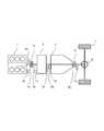
- FIG. 1shows a configuration diagram of a powertrain of a hybrid vehicle according to an embodiment of the present invention. As shown in FIGS. 15 and 16, the configuration of the power train of the hybrid vehicle, in particular, the position of the second clutch 5 is not limited to that shown in FIG.
- an engine 1that is a driving force source as an internal combustion engine and a motor generator 2 that generates driving force by electric power are arranged in series in the traveling direction of the vehicle. These driving forces are shifted by the automatic transmission 3 and output to the drive wheels 7 via the differential gear 6.
- the motor generator 2acts as a motor to generate a driving force or acts as a generator to generate electric power.
- crankshaft (output shaft) 1 a of the engine 1 and the input shaft 2 a of the motor generator 2are connected via a first clutch 4.
- the output shaft 2 b of the motor generator 2is connected to the input shaft 3 a of the automatic transmission 3.
- a differential gear 6is connected to the output shaft 3 b of the automatic transmission 3.
- the automatic transmission 3selectively engages and disengages a plurality of friction elements (such as clutches and brakes), and selects a transmission path by a combination of these friction elements to determine a gear position. Therefore, the automatic transmission 3 shifts the rotation from the input shaft 3a to a gear ratio corresponding to the selected gear position, and outputs it to the output shaft 3b.
- a plurality of friction elementssuch as clutches and brakes
- the automatic transmission 3uses one of the plurality of friction elements as the second clutch 5.
- the automatic transmission 3combines the power of the engine 1 input via the first clutch 4 and the power input from the motor generator 2 and outputs the combined power to the drive wheels 7.
- the first clutch 4is constituted by, for example, a dry clutch whose fastening state is controlled by hydraulic pressure.
- the second clutchis a wet multi-plate clutch whose capacity is controlled by hydraulic pressure. Any of them may be constituted by a dry clutch or a wet multi-plate clutch.
- the first clutch 4includes a stroke sensor 23 that detects the stroke amount of the first clutch 4.
- the output shaft 1 a of the engine 1includes an engine rotation speed sensor 10 that detects the rotation speed Ne of the engine 1.
- the input shaft 2 a of the motor generator 2includes a motor generator rotational speed sensor 11 that detects the rotational speed Nm of the motor generator 2.
- the automatic transmission 3includes an automatic transmission input shaft rotational speed sensor 12 that detects an input shaft rotational speed Ni of the automatic transmission 3, and an automatic transmission output shaft rotational speed that detects an output shaft rotational speed No of the automatic transmission 3.
- a sensor 13is an automatic transmission input shaft rotational speed sensor 12 that detects an input shaft rotational speed Ni of the automatic transmission 3, and an automatic transmission output shaft rotational speed that detects an output shaft rotational speed No of the automatic transmission 3.
- the signals output by these sensorsare output to the integrated controller 20 described later in FIG.
- the power train of the hybrid vehicle configured as described abovehas three travel modes according to the engaged state of the first clutch 4.
- the first travel modeis an electric travel mode (hereinafter referred to as “EV mode”) in which the first clutch 4 is in the released state and travels only with the power of the motor generator 2.
- EV modeelectric travel mode
- the second traveling modeis a hybrid traveling mode (hereinafter referred to as “HEV mode”) in which the first clutch 4 is engaged and traveling using the power of both the engine 1 and the motor generator 2.
- HEV modehybrid traveling mode
- the third running modeis a slip running mode (hereinafter referred to as “WSC (Wet Start Clutch) mode) in which the first clutch 4 is engaged and the second clutch 5 is slip controlled to run with the power of the engine 1 and the motor generator 2. ").
- WSCWeight Start Clutch
- the WSC moderealizes creep running particularly when the battery SOC is low or the engine water temperature is low. In this mode, the driving force can be output while starting the engine 1 when the engine 1 starts from a stopped state.
- the accelerator hill holdis performed in which the driver adjusts the accelerator pedal and maintains the vehicle stop state when the load on the vehicle is large (for example, an uphill or the like when the road surface gradient is a predetermined value or more) .
- the excessive slip amount of the second clutch 5may be continued. This is because the rotational speed of the engine 1 cannot be made smaller than the idle rotational speed, and therefore a rotational difference is generated by the slip of the second clutch 5.
- the first clutch 4is released while the engine 1 is operated, and the second clutch 5 is slip-controlled while the motor generator 2 is operated.
- 2further includes a motor slip traveling mode (hereinafter abbreviated as “MWSC mode”) that travels using 2 as a power source.
- MWSC modemotor slip traveling mode
- the HEV modeincludes an “engine running mode”, a “motor assist running mode”, and a “running power generation mode”.
- the engine running modeis a mode for driving the drive wheels 7 using only the engine 1 as a drive source.
- the motor assist travel modeis a mode in which both the engine 1 and the motor generator 2 travel using the drive sources.
- the traveling power generation modeis a mode in which the motor generator 2 is caused to function as a generator by the driving force of the engine 1 while traveling with the engine 1 as a drive source.
- the second clutch 5 located between the motor generator 2 and the drive wheel 7uses any one of the frictional engagement elements in the automatic transmission 3 as the second clutch 5.
- the second clutch 5may be interposed between the motor generator 2 and the automatic transmission 3.
- the second clutch 5may be interposed between the automatic transmission 3 and the differential gear 6.
- the integrated controller 20controls the engine 1, the motor generator 2, the first clutch 4, the second clutch 5, and the like, and switches the traveling mode.
- FIG. 2is a configuration block diagram of a hybrid system including the integrated controller 20.
- the hybrid systemincludes an integrated controller 20, an engine controller 21, a motor generator controller 22, an inverter 8, a battery 9, and the like.
- Integral controller 20receives signals from engine speed sensor 10, motor generator speed sensor 11, automatic transmission input shaft speed sensor 12, automatic transmission output shaft speed sensor 13, and stroke sensor 23.
- the integrated controller 20receives signals from the G sensor 10b for detecting the road surface gradient and the brake hydraulic pressure sensor 24 for detecting the brake hydraulic pressure of the brake device.
- the integrated controller 20determines the operating point of the powertrain according to the accelerator opening APO, the battery state of charge SOC, and the vehicle speed VSP (proportional to the automatic transmission output shaft rotational speed No), and the driving force desired by the driver Select a driving mode that can realize
- the integrated controller 20is instructed to the motor generator controller 22 with the target motor generator torque or the target motor generator rotational speed.
- the target engine torqueis designated to the engine controller 21.
- the integrated controller 20is instructed to drive signals to the solenoid valve 14 that controls the hydraulic pressure of the first clutch 4 and the solenoid valve 15 that controls the hydraulic pressure of the second clutch 5.
- the engine controller 21controls the engine 1 so that the engine torque becomes the target engine torque.
- the AT controller 30controls the gear ratio of the automatic transmission 30.
- the motor generator controller 22controls the motor generator 2 via the battery 9 and the inverter 8 so that the torque of the motor generator 2 becomes the target motor generator torque (or the rotational speed of the motor generator becomes the rotational speed of the target motor generator). Control.
- the power generation torque of the motor generatoris controlled so that the motor generator 2 becomes the target power generation torque.
- the inverter 8converts the power of the battery 9 into a high frequency current and supplies it to the motor generator 2. When the motor generator 2 is in the power generation state, the generated power is converted into a direct current and the battery 9 is charged.
- control calculated by the integrated controller 20will be described.
- the calculationis performed by the integrated controller 20 every control cycle of 10 msec.
- FIG. 3is a functional block diagram of the integrated controller 20.
- the integrated controller 20includes a target driving force calculation unit 100, a mode selection unit 200, a target charge / discharge calculation unit 300, an operating point command unit 400, and a shift control unit 500.
- the target driving force calculation unit 100calculates the target driving force tFoO from the accelerator opening APO and the vehicle speed VSP using the target driving force map shown in FIG.
- the mode selection unit 200includes a road surface gradient estimation calculation unit 201 that estimates a road surface gradient based on the detection value of the G sensor 10b.
- the road surface gradient estimation calculation unit 201calculates the actual acceleration from the wheel speed acceleration average value of the wheel speed sensor 19 and the like, and estimates the road surface gradient from the deviation between the calculation result and the G sensor detection value.
- the mode selection unit 200includes a mode map selection unit 202 that selects one of two mode maps described below based on the estimated road gradient.
- FIG. 5is a schematic diagram showing the selection logic of the mode map selection unit 202.
- the mode map selection unit 202switches to the MWSC compatible mode map when the estimated gradient is equal to or greater than the predetermined value g2 from the state where the normal mode map is selected.
- the modeis switched to the normal mode map.
- g1is set to a value smaller than g2, and a hysteresis is provided for the estimated gradient to prevent control hunting during map switching.
- the mode mapincludes a normal mode map that is selected when the estimated gradient is less than a predetermined value, and a MWSC-compatible mode map that is selected when the estimated gradient is greater than or equal to a predetermined value.
- 6shows a normal mode map
- FIG. 7shows a MWSC mode map.
- the normal mode maphas an EV mode, a WSC mode, and an HEV mode.
- the integrated controller 20calculates a target mode from the accelerator opening APO and the vehicle speed VSP based on the normal mode map. Even if the EV mode is selected, if the battery state of charge SOC is equal to or less than a predetermined value, the “HEV mode” is forcibly set as the target mode.
- the HEV ⁇ WSC switching linehas a rotational speed smaller than the idle rotational speed of the engine 1 when the automatic transmission AT is in the first speed in the region less than the predetermined accelerator opening APO1. It is set to a region lower than the lower limit vehicle speed VSP1.
- the WSC modeis set up to a vehicle speed VSP1 'region that is higher than the lower limit vehicle speed VSP1.
- the WSC modeis selected even when starting.
- the MWSC mode map in FIG. 7is different from the normal mode map in that the EV mode area is not set.
- the WSC mode regionis different from the normal mode map in that the region is defined only by the lower limit vehicle speed VSP1 without changing the region according to the accelerator opening APO. It differs from the normal mode map in that the MWSC mode area is set in the WSC mode area.
- the MWSC mode areais set in an area surrounded by a predetermined vehicle speed VSP2 lower than the lower limit vehicle speed VSP1 and a predetermined accelerator opening APO2 higher than the predetermined accelerator opening APO1. Details of the MWSC mode will be described later.
- the target charge / discharge calculation unit 300calculates the target charge / discharge power tP from the battery charge state SOC using the target charge / discharge amount map shown in FIG.
- the operating point command unit 400uses the accelerator opening APO, the target driving force tFoO, the target mode, the vehicle speed VSP, and the target charging / discharging power tP as a target for reaching these operating points, A target motor generator torque, a target second clutch transmission torque capacity, a target gear position of the automatic transmission AT, and a first clutch solenoid current command are calculated.
- the operating point command unit 400is provided with an engine start control unit that starts the engine 1 when transitioning from the EV mode to the HEV mode.
- the shift control unit 500outputs a command to the AT controller 30 to achieve the target second clutch transmission torque capacity and the target shift speed according to the shift schedule shown in the shift map.
- a target gear positionis set in advance based on the vehicle speed VSP and the accelerator opening APO.
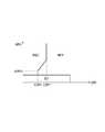
- the estimated gradientis larger than the predetermined gradient (g1 or g2), for example, if it is attempted to maintain the vehicle in the stop state or the slow start state without operating the brake pedal, a large driving force is required as compared with a flat road. . This is because it is necessary to face the load load of the host vehicle.
- a lock current(a phenomenon in which current continues to flow through one element) flows in the switching element of the inverter.
- the lock currentmay cause a decrease in durability.
- the engine 1itself cannot be lowered below the idle rotation speed in a region lower than the lower limit vehicle speed VSP1 (region below VSP2) corresponding to the idle rotation speed of the engine 1. .
- VSP1region below VSP2
- the slip amount of the second clutch 5increases, which may affect the durability of the second clutch 5.
- the first clutch 4is disengaged while the engine 1 is operated, and the rotational speed of the motor generator 2 is controlled by the second clutch 5 while controlling the transmission torque capacity of the second clutch 5 to the driver's requested driving force.
- the MWSC modein which feedback control is performed to a target rotational speed that is higher than the output rotational speed by a predetermined rotational speed is set.
- the second clutch 5is slip-controlled while the rotational state of the motor generator 2 is set to a rotational speed lower than the idle rotational speed of the engine 1.
- the engine 1is switched to feedback control in which the idle rotation speed is set to the target rotation speed.
- the engine rotation speedis maintained by the rotation speed feedback control of the motor generator 2.
- the motor generator 2cannot control the engine rotation speed to the idle rotation speed. Therefore, engine speed feedback control is performed by the engine 1 itself.
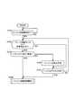
- FIG. 9is a flowchart of the travel control process in the MWSC mode according to the embodiment of the present invention.
- the flowchart shown in FIG. 9is executed by the integrated controller 20 at a predetermined cycle (for example, every 10 ms).
- step S1the integrated controller 20 determines whether or not the normal mode map is selected. When the normal mode map is selected, the process proceeds to step S2, and when the MWSC compatible mode map is selected, step S11 is performed. Proceed to
- step S2the integrated controller 20 determines whether or not the estimated gradient is larger than the predetermined value g2. If so, the process proceeds to step S3. Otherwise, the process proceeds to step S15 to perform control processing based on the normal mode map.
- the predetermined value g2is a gradient determination threshold value for determining whether the current road surface is in a gradient state. For example, the predetermined value g2 is set to 8%, and when the estimated gradient exceeds the predetermined value, it is determined that the gradient is a gradient. Details of the processing in step S2 will be described later.
- step S3the integrated controller 20 switches from the normal mode map to the MWSC compatible mode map.
- step S4the integrated controller 20 determines whether or not the operating point determined by the current accelerator opening APO and the vehicle speed VSP is within the MWSC mode region. If it is determined that the operating point is within the region, the process proceeds to step S5. In other cases, the process proceeds to step S8.
- step S5the integrated controller 20 determines whether or not the battery state of charge SOC is larger than the predetermined value A. If it is larger than the predetermined value A, the process proceeds to step S6. Otherwise, the process proceeds to step S9.
- the predetermined value Ais a threshold value for determining whether or not the driving force can be secured only by the motor generator 2.
- the SOCis larger than the predetermined value A, the driving force can be ensured only by the motor generator 2.
- the SOCis lower than the predetermined value A, the battery 9 needs to be charged, so selection of the MWSC mode is prohibited.
- step S6the integrated controller 20 determines whether or not the transmission torque capacity TCL2 of the second clutch 5 is less than the predetermined value B. If it is less than the predetermined value B, the process proceeds to step S7, otherwise the process proceeds to step S9. .
- the predetermined value Bis a predetermined value indicating that an excessive current does not flow through the motor generator 2. Since the motor generator 2 is controlled in rotational speed, the torque generated in the motor generator 2 is greater than or equal to the load acting on the motor generator 2.
- step S7the integrated controller 20 executes MWSC control processing. Specifically, if the engine 1 is stopped, the engine 1 is started, and the first clutch 4 is released while the engine 1 is in an operating state.
- the integrated controller 20performs feedback control so that the engine 1 is at the idle rotation speed.
- the motor generator 2performs feedback control to obtain a target rotational speed (a value lower than the idle rotational speed) obtained by adding the predetermined rotational speed ⁇ to the output-side rotational speed Ncl2out of the second clutch 5.
- the second clutch 5is feedback controlled to have a transmission torque capacity corresponding to the required driving force.
- the MWSC control process in step S7includes a mode transition process from the EV mode or the WSC mode.
- the transitionis from the EV mode to the MWSC mode, the engine 1 is started.
- step S8the integrated controller 20 determines whether or not the operating point determined by the current accelerator opening and the vehicle speed is within the WSC mode region. If it is determined that the operating point is within the region, the process proceeds to step S9. Otherwise, it is determined that it is in the HEV mode area and the process proceeds to step S10.
- step S9the integrated controller 20 executes WSC control processing. Specifically, the first clutch 4 is completely engaged, and the engine 1 performs feedforward control according to the target torque. The motor generator 2 performs feedback control at an idle rotation speed. The second clutch 5 performs feedback control with a transmission torque capacity corresponding to the required driving force.
- the WSC control process in step S9includes a mode transition process from the EV mode.
- step S10the integrated controller 20 executes HEV control processing. Specifically, the first clutch 4 is completely engaged, the feedforward control is performed so that the engine 1 and the motor generator 2 have a torque corresponding to the required driving force, and the second clutch 5 is completely engaged. Since the EV mode is not set in the MWSC compatible mode map, the HEV control process in step S10 includes a mode transition process from the EV mode.
- step S11the integrated controller 20 determines whether or not the estimated gradient is less than the gradient release determination threshold g1, and if it is less than g1, the process proceeds to step S12. Otherwise, the process proceeds to step S4 and is based on the MWSC compatible mode map. Continue control.
- the gradient cancellation determination threshold value g1is a value obtained by setting hysteresis to the gradient determination threshold value g2. For example, the gradient cancellation determination threshold value g1 is set to 5% obtained by subtracting the hysteresis from the gradient determination threshold value g2, and it is determined that the gradient is canceled when the estimated gradient is less than a predetermined value. Details of step S11 will be described later.
- step S12the integrated controller 20 switches from the MWSC compatible mode map to the normal mode map.
- step S13the integrated controller 20 determines whether or not the travel mode has been changed in accordance with the map switching. If it is determined that the travel mode has been changed, the process proceeds to step S14. Otherwise, the process proceeds to step S15. This is because switching from the MWSC compatible mode map to the normal mode map can cause a transition from the MWSC mode to the WSC mode, a transition from the WSC mode to the EV mode, and a transition from the HEV mode to the EV mode.
- step S14the integrated controller 20 executes a travel mode change process. Specifically, at the time of transition from the MWSC mode to the WSC mode, the target rotational speed of the motor generator 2 is changed to the idle rotational speed, and the first clutch 4 is engaged at the synchronized stage. Then, the engine control can be switched from the idle rotation speed feedback control to the target engine torque feedforward control.
- the integrated controller 20releases the first clutch 4, stops the engine 1, switches the motor generator 2 from the rotational speed control to the torque control based on the requested driving force, 2
- the clutch 5is switched from feedback control based on the required driving force to complete engagement.
- the integrated controller 20releases the first clutch 4, stops the engine 1, the motor generator 2 continues the torque control based on the requested driving force, and the second clutch 5 Is switched from feedback control based on the required driving force to complete fastening.
- step S15the integrated controller 20 executes a control process based on the normal mode map.
- the gradientis determined and the MWCS mode is selected.
- the gradient release determination threshold value g1 in which hysteresis is set to a predetermined value g2 that is a gradient determination threshold valuethe gradient determination is canceled, the MWSC mode is canceled, and control based on the normal mode map is performed. Is called.
- the MWSC modeis selected when the estimated gradient is larger than the predetermined value g2.
- the engine 1is started. In other words, the engine 1 is started when the estimated gradient is larger than the predetermined value g2.
- the integrated controller 20performs control so that the engine is started when a condition described below is satisfied.
- FIG. 10is a flowchart showing engine start control according to the embodiment of the present invention.
- the flowchart shown in FIG. 10is executed by the integrated controller 20 at a predetermined cycle (for example, every 10 ms).
- step S101the integrated controller 20 determines whether or not there is an engine start request. If there is an engine start request, the process proceeds to step S102, and otherwise, this step is repeated.
- the engine 1is requested to start when the estimated gradient is larger than the predetermined value g2 in step S3 of FIG.
- step S102the integrated controller 20 determines whether or not the brake braking force is greater than the predetermined braking force B and the vehicle stop determination is ON based on a signal from the brake hydraulic pressure sensor 24. If the condition is satisfied, the process proceeds to step S103, and otherwise, the process proceeds to step S105.
- the stop determinationis to determine that the vehicle is almost stopped when the state where the vehicle speed VSP is equal to or lower than a predetermined value continues for a predetermined time or longer. The vehicle is not always completely stopped.
- the integrated controller 20controls the creep torque of the motor generator 2 to gradually decrease toward 0 Nm. This is because if the brake braking force is greater than the predetermined braking force B, the driver intends to brake and it is considered that torque fluctuations acting on the wheels can be suppressed to some extent.
- step S103the integrated controller 20 determines whether or not the state where the absolute value of the input torque (that is, the output torque of the motor generator 2) is 0 or less has passed the specified time T1. If it is determined that the condition is satisfied, the process proceeds to step S106. Otherwise, the process proceeds to step S104.
- the input torqueis determined using the command torque to the motor generator 2, but the torque may be estimated based on the current value supplied to the motor generator 2, and the like. Alternatively, the input torque may be detected using a torque sensor or the like.
- step S104the integrated controller 20 waits for the engine to start. Thereby, when there is a possibility that the output torque of the motor generator 2 may fluctuate, it is possible to avoid the uncomfortable feeling given to the driver by avoiding the engine start.
- step S105the integrated controller 20 determines whether or not the range position is the P range or the accelerator pedal is ON. When these conditions are satisfied, the process proceeds to step S106, and otherwise, the process returns to step S102.
- the wheelis forcibly fixed by the operation of the parking lock mechanism, so that the influence of torque fluctuation can be suppressed even if input torque is generated. This is because it is appropriate to start the engine 1 immediately since the driver intends to start when the accelerator pedal is turned on.
- step S106the integrated controller 20 starts an engine start control process. As a result, the engine 1 is started.
- the integrated controller 20waits for the engine to start when the motor generator 2 is outputting torque. As a result, it is possible to prevent the driver from feeling uncomfortable due to vibration due to the influence of torque fluctuation. That is, the integrated controller 20 constitutes an engine start control unit that starts the engine when the engine start conditions based on the torque of the motor generator 2, the range position, or the state of the accelerator pedal are satisfied.
- the integrated controller 20makes a start request for the engine 1 when the MWSC mode is selected.
- engine start controlis performed according to the flowchart shown in FIG.
- the engine 1performs a so-called idle stop for the purpose of suppressing fuel consumption when the vehicle decelerates and the accelerator opening APO is in a small coast state or when the vehicle stops. To do. As a result, the engine 1 stops.
- the integrated controller 20determines that the road gradient is greater than the predetermined value g2 and shifts to the MWSC mode, for example, when the engine 1 cannot be started immediately, such as when the output torque of the motor generator 2 is not 0 Nm. Garage.
- the embodiment of the present inventionis configured to prevent such a sense of incongruity by performing the following control.
- FIG. 11is a flowchart of the gradient determination process according to the embodiment of the present invention.
- the flowchart shown in FIG. 11corresponds to the process in step S2 of the flowchart in FIG.
- step S2 of FIG. 9the integrated controller 20 determines whether or not the estimated gradient is larger than the predetermined value g2. If the estimated gradient is larger than the predetermined value g2, the process proceeds to step S3, and transitions to the MWSC mode.
- the integrated controller 20continuously detects that the current road surface estimated gradient is larger than a predetermined value g2 that is a gradient determination threshold value for a first predetermined time or more. It is determined whether or not.
- the first predetermined timeis a continuous time provided to eliminate the influence of noise included in the detection value of the G sensor 10b, vibration or swing of the running vehicle, and is 1 second, for example.
- step S21the integrated controller 20 determines that the gradient state is present, and the gradient state determination is performed. Hold the result. That is, the determination in step S2 in FIG. 9 is YES.
- step S22the integrated controller 20 determines that the gradient is not a gradient. That is, the determination in step S2 in FIG. 9 is NO.
- the integrated controller 12determines that the vehicle is in the gradient state, thereby configuring a gradient determination control unit.
- FIG. 12is a flowchart of the gradient release determination process according to the embodiment of the present invention.
- the flowchart shown in FIG. 12corresponds to the process in step S11 of the flowchart in FIG.
- step S11 of FIG. 9the integrated controller 20 determines whether or not the estimated gradient is less than the gradient cancellation determination threshold value g1, and when it is less than the gradient cancellation determination threshold value g1, the process proceeds to step S12 and the MWSC mode is set. It cancels and it changes to the driving mode using a normal mode map.
- the release of the MWSC modeis further controlled under the following conditions.
- step S31the integrated controller 20 determines whether or not the hybrid vehicle is stopped. If it is determined that the vehicle is stopped, the process proceeds to step S32. If it is determined that the vehicle is not stopped, the process proceeds to step S35.
- the determination in step S31determines that the vehicle is stopped when the vehicle speed VSP is 0 or several km / h or less, for example.
- the integrated controllerdetermines whether the vehicle is in a traveling state or in a stopped state based on the vehicle speed VSP as described above, thereby configuring a traveling state determination unit.
- step S32the integrated controller 20 determines whether or not the estimated road surface gradient is less than a predetermined value g2 that is a gradient determination threshold value.
- step S33the integrated controller 20 determines that the road surface gradient is not a gradient (if the gradient determination result is retained, it is canceled). That is, the determination in step S11 in FIG. 9 is YES.
- step S34the integrated controller 20 determines that the gradient is determined (holds the previously determined gradient determination result). That is, the determination in step S11 in FIG. 9 is NO.
- step S32 to S34are to immediately cancel the result of the slope determination if the slope determination is less than the threshold value when the vehicle is stopped. This is because when the vehicle is stopped, there is little error or noise in the value of each sensor used to detect the gradient. Therefore, even if the gradient determination is immediately canceled by comparing the estimated gradient with the predetermined value g2 for which no hysteresis is set. This is because there is no problem.
- step S31If it is determined in step S31 that the vehicle is traveling, the process proceeds to step S35, and the integrated controller 20 compares the estimated gradient with a gradient release determination threshold g1 in which hysteresis is set for the gradient determination threshold g2. Then, it is determined whether or not a state in which the estimated gradient is less than the gradient release determination threshold g1 is continuously detected for the second predetermined time or more.
- the second predetermined timeis a continuous time provided in order to eliminate the influence of noise included in the detection value of the G sensor 10b, vibration or swinging of the running vehicle, for example, 1 second.
- step S36the integrated controller 20 determines that the road surface gradient is not a gradient (gradient determination result). If is held, cancel this). That is, the determination in step S11 in FIG. 9 is YES.
- step S37the integrated controller 20 determines that the gradient has been determined last time. Holds the gradient judgment result. That is, the determination in step S11 in FIG. 9 is NO.
- the integrated controllerdetermines the gradient determination result that the road surface is in the gradient state and holds this, or releases the retention of the gradient determination result, thereby configuring the gradient determination control unit.
- FIG. 13is an explanatory diagram showing control when the vehicle stops in the embodiment of the present invention.
- the estimated gradient, vehicle speed, and gradient determination stateare shown as time charts with time on the horizontal axis.
- FIG. 13shows a driving state in which the vehicle decelerates and stops at timing t13.
- the gradient of the road surface at this timeincreases with the progress of the vehicle, and after the estimated gradient exceeds the predetermined value g2, the estimated gradient is between g1 and g2 (hysteresis range) almost simultaneously with the stop of the vehicle. Shows the state.
- the estimated gradientgradually increases with the progress of the vehicle, and the estimated gradient becomes equal to or greater than the predetermined value g2 at timing t11.
- the determinationis YES in step S21 of FIG. 11 described above, and the gradient is determined.
- the vehicleis decelerated, the vehicle speed is substantially 0 km / h at timing t13, and the vehicle is stopped. It is assumed that the estimated gradient becomes a gradient between the gradient release determination threshold value g1 and the predetermined value g2 before and after the timing t13.
- the gradient determinationis not canceled if step S11 of FIG. 9 described above is followed.
- the gradient determinationremains, so that, for example, when idling stop is being performed, the engine 1 is started by shifting to the MWSC mode.
- the gradient determinationis canceled and the engine 1 stops immediately.
- the determination in step S21 in FIG.Cancel the judgment.
- the engine 1is prevented from stopping after starting without shifting to the MWSC mode.
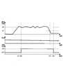
- FIG. 14is an explanatory diagram showing control during travel of the vehicle in the embodiment of the present invention.
- the estimated gradient, vehicle speed, and gradient determination stateare shown as time charts with time as the horizontal axis.
- FIG. 14shows a state in which the estimated gradient exceeds the predetermined value g2 at timing t21 while the vehicle is traveling, and then the estimated gradient is less than the gradient cancellation determination threshold value g1 at timing t23.
- the estimated gradientbecomes a predetermined value g2 or more.
- the determinationis YES in step S21 of FIG. 11 described above, and the gradient is determined.
- the estimated gradientexceeds or falls below the gradient determination threshold value g2.
- the gradient determinationis canceled when it falls below g2. There is no.
- timing t23when the estimated gradient is less than the gradient cancellation determination threshold g1, and this state continues for the second predetermined time (timing t24), the determination is YES in step S34 of FIG. Is done.
- the embodiment of the present inventionis applied to a hybrid vehicle including the engine 1 and the motor generator 2 as drive sources.
- the hybrid vehicleincludes a road surface gradient estimation calculation unit 201 as a road surface gradient detection unit that detects a road surface gradient based on a detection value of the G sensor 10b.
- a gradient determination control unitis provided.
- An engine start control unitthat starts the engine 1 when the gradient determination result is held by the gradient determination control unit and the start permission condition of the engine 1 is satisfied.
- a traveling state determination unitthat determines whether the hybrid vehicle is in a traveling state or a stopped state is provided. These are constituted by the integrated controller 20.
- the integrated controller 20determines that the vehicle is in a traveling state as a condition for releasing the retention of the gradient determination result that the road surface is a gradient road, the road gradient is determined for the gradient determination.
- the state of being smaller than the threshold value g2has continued for the second predetermined time or longer, the retention of the gradient determination result is released.
- the integrated controller 20cancels the retention of the gradient determination result when the road surface gradient becomes smaller than the gradient cancellation determination threshold value g1.
- Such controlprevents the engine from starting in a non-gradient state, for example, when the road surface is no longer at the same time as the vehicle stops. For example, in a road surface state in which the vehicle stops after holding the gradient determination result and the road surface gradient disappears simultaneously with the stop of the vehicle, the holding of the gradient determination result can be released, and the engine start can be suppressed. . Thereby, it is possible to prevent the driver from feeling uncomfortable due to the engine starting, and to suppress fuel consumption. As a result, the vibration noise of the engine is prevented and the driver is prevented from feeling uncomfortable, and fuel consumption can be suppressed.
- the gradient determination threshold value g2 for determining the gradient and the gradient cancellation determination threshold value g1 for determining release of retention of the gradient determination resultmay be the same value (for example, a predetermined value g2).
- the predetermined value g2 that is the gradient determination threshold valueis set to a value that is larger than the gradient cancellation determination threshold g1 for canceling the gradient determination by a hysteresis, but when the vehicle is stopped, the gradient determination threshold value The cancellation is performed by the gradient determination threshold value g2.
- the region for canceling the gradient determinationcan be further expanded, so that the start of the engine is suppressed, the vibration noise of the engine is prevented and the driver is prevented from feeling uncomfortable, and the fuel consumption is reduced. Can be suppressed.
- the determinationis made when the road surface gradient is greater than the gradient determination threshold value g2 for a first predetermined time or more.
- the influence of the noise of the detection signal of the G sensor 10b or the shaking of the vehicle body unrelated to the road surface changeis eliminated by the first predetermined time. can do.
Landscapes
- Engineering & Computer Science (AREA)
- Chemical & Material Sciences (AREA)
- Combustion & Propulsion (AREA)
- Transportation (AREA)
- Mechanical Engineering (AREA)
- Automation & Control Theory (AREA)
- Physics & Mathematics (AREA)
- Mathematical Physics (AREA)
- Hybrid Electric Vehicles (AREA)
- Electric Propulsion And Braking For Vehicles (AREA)
Abstract
Description
Translated fromJapaneseこの発明は、エンジン及び電動機を駆動力源とするハイブリッド車両の制御装置に関する。The present invention relates to a hybrid vehicle control apparatus using an engine and an electric motor as driving force sources.
エンジン及びモータの少なくとも一方の動力を用いて車両を駆動させると共に、モータを発電機としてバッテリに蓄電可能なハイブリッド車両が実用化されている。ハイブリッド車両において、エンジン及びモータの動力を摩擦締結要素(クラッチ)によって駆動軸へと断続させる構造が知られている。エンジンとモータとの間に第1のクラッチが介装され、モータと駆動輪との間に第2のクラッチが介装される。A hybrid vehicle capable of driving a vehicle using the power of at least one of an engine and a motor and storing the battery in a battery using the motor as a generator has been put into practical use. In a hybrid vehicle, a structure in which power of an engine and a motor is intermittently connected to a drive shaft by a friction engagement element (clutch) is known. A first clutch is interposed between the engine and the motor, and a second clutch is interposed between the motor and the drive wheel.
このようなハイブリッド車両として、JP2009-132195Aには、車両の負荷が所定値以上のとき、エンジンを作動させた状態で第1のクラッチを解放し、モータをエンジン回転速度よりも低い回転速度として第2のクラッチをスリップ締結させるハイブリッド車両の制御装置が開示されている。As such a hybrid vehicle, JP2009-132195A discloses that when the vehicle load is equal to or higher than a predetermined value, the first clutch is released while the engine is operated, and the motor is set to a rotational speed lower than the engine rotational speed. A control apparatus for a hybrid vehicle in which two clutches are slip-engaged is disclosed.
JP2009-132195Aに記載の技術では、車両の負荷が大きい場合、例えば、路面勾配が大きい場合に、第2のクラッチをスリップ制御してハイブリッド車両を駆動している。In the technique described in JP2009-132195A, when the load on the vehicle is large, for example, when the road surface gradient is large, the second clutch is slip-controlled to drive the hybrid vehicle.
このような制御において、走行中に路面勾配は常に変化するため、勾配を検出してからエンジンを始動させる場合には、エンジン始動、停止のハンチングが発生しないように、勾配に対するヒステリシスを設定する。In such control, since the road surface gradient always changes during traveling, when starting the engine after detecting the gradient, hysteresis for the gradient is set so that hunting of engine start and stop does not occur.
しかしながら、勾配を検出したとき、車両の状態により直ちにエンジンが始動できない場合がある。この場合、車両の状態が変化して、その後エンジンの始動が可能となった場合に、既に勾配を通過している可能性がある。この状態において、前述のヒステリシスや制御タイミングの遅れ等により、エンジンが一旦始動した後にすぐにエンジンが停止するという動作が発生し、運転者に違和感を与えるばかりか、燃料が無駄になるという問題があった。However, when the slope is detected, the engine may not start immediately depending on the vehicle condition. In this case, there is a possibility that the vehicle has already passed through the gradient when the state of the vehicle changes and the engine can be started thereafter. In this state, there is a problem that the engine stops immediately after the engine is started once due to the hysteresis or the delay of the control timing described above, which not only gives the driver a sense of incongruity but also wastes fuel. there were.
本発明はこのような問題点に鑑みてなされたものであり、エンジンの始動、停止による違和感を防止できるハイブリッド車両の制御装置を提供することを目的とする。The present invention has been made in view of such problems, and an object of the present invention is to provide a control device for a hybrid vehicle that can prevent a sense of incongruity due to engine start and stop.
本発明の一実施態様によると、車両の駆動源としてのエンジン及びモータと、路面の勾配を検出する勾配検出部と、エンジンが停止状態であり、かつ、勾配路検出部によって検出された路面勾配が勾配判定用閾値以上である状態が第1所定時間以上継続したときに、路面が勾配路であると判定し、その勾配判定結果を保持する勾配判定制御部と、勾配判定制御部によって勾配判定結果が保持され、かつ、エンジンの始動許可条件が満足したときに、エンジンを始動するエンジン始動制御部と、車両が走行状態であるか停止状態であるかを判定する走行状態判定部と、を備える。According to one embodiment of the present invention, an engine and a motor as a vehicle drive source, a gradient detection unit that detects a gradient of a road surface, and a road surface gradient that is detected by the gradient road detection unit when the engine is stopped. Is determined to be sloped by a slope judgment control unit that determines that the road surface is a sloped road and holds the slope judgment result when the state where the slope is equal to or greater than the slope judgment threshold continues for a first predetermined time or more. An engine start control unit that starts the engine and a running state determination unit that determines whether the vehicle is in a running state or a stopped state when the result is held and the engine start permission condition is satisfied; Prepare.
勾配判定制御部は、路面が勾配路であるとの勾配判定結果の保持を解除する条件として、走行状態判定部によって、車両が走行状態であると判定された場合には、勾配検出部によって検出された路面勾配が勾配解除判定用閾値よりも小さくなった状態が第2所定時間以上継続した場合に、勾配判定結果の保持を解除する一方、走行状態判定部によって、車両が停止状態であると判定された場合には、勾配検出部によって検出された路面勾配が、勾配解除判定用閾値よりも小さくなった場合に、勾配判定結果の保持を解除することを特徴とする。The gradient determination control unit detects, by the gradient detection unit, when the traveling state determination unit determines that the vehicle is in a traveling state as a condition for releasing the retention of the gradient determination result that the road surface is a gradient road. When the state where the road surface gradient is smaller than the gradient release determination threshold continues for the second predetermined time or longer, the holding of the gradient determination result is canceled, while the vehicle is stopped by the traveling state determination unit. When the determination is made, when the road surface gradient detected by the gradient detection unit is smaller than the gradient cancellation determination threshold, the retention of the gradient determination result is canceled.
本発明の実施形態、本発明の利点については、添付された図面を参照しながら以下に詳細に説明する。Embodiments of the present invention and advantages of the present invention will be described in detail below with reference to the accompanying drawings.
以下、本発明の実施形態を図面に基づいて詳細に説明する。Hereinafter, embodiments of the present invention will be described in detail with reference to the drawings.
図1は、本発明の実施形態のハイブリッド車両のパワートレインの構成図を示す。図15、図16に示したように、ハイブリッド車両のパワートレインの構成、特に第2クラッチ5の位置は図1に示すものに限定されない。FIG. 1 shows a configuration diagram of a powertrain of a hybrid vehicle according to an embodiment of the present invention. As shown in FIGS. 15 and 16, the configuration of the power train of the hybrid vehicle, in particular, the position of the
図1に示すハイブリッド車両のパワートレインは、内燃機関としての駆動力源であるエンジン1と、電力によって駆動力を発生するモータジェネレータ2とが、車両の進行方向に直列に配置されている。これらの駆動力は、自動変速機3により変速されて、ディファレンシャルギア6を介して駆動輪7に出力される。In the power train of the hybrid vehicle shown in FIG. 1, an
モータジェネレータ2は、モータとして作用して駆動力を発生したり、ジェネレータとして作用して電力を発生させる。The
エンジン1のクランクシャフト(出力軸)1aとモータジェネレータ2の入力軸2aとは、第1クラッチ4を介して連結される。モータジェネレータ2の出力軸2bは、自動変速機3の入力軸3aに連結される。自動変速機3の出力軸3bは、ディファレンシャルギア6が接続される。The crankshaft (output shaft) 1 a of the
自動変速機3は、複数の摩擦要素(クラッチやブレーキ等)を選択的に締結及び解放することによって、これら摩擦要素の組み合わせにより伝達経路を選択して変速段を決定する。従って自動変速機3は、入力軸3aからの回転を、選択された変速段に応じた変速比に変速して出力軸3bに出力する。The
自動変速機3は、複数の摩擦要素のうちの1つを第2クラッチ5として用いる。自動変速機3は、第1クラッチ4を介して入力されるエンジン1の動力と、モータジェネレータ2から入力される動力を合成して駆動輪7へ出力する。The
第1クラッチ4は、例えば、油圧によって締結状態が制御される乾式クラッチにより構成される。第2クラッチは、油圧によって容量が制御される湿式多板クラッチにより構成される。いずれも、乾式クラッチ又は湿式多板クラッチにより構成されていてもよい。The
第1クラッチ4は、第1クラッチ4のストローク量を検出するストロークセンサ23を備える。The
エンジン1の出力軸1aは、エンジン1の回転速度Neを検出するエンジン回転速度センサ10を備える。モータジェネレータ2の入力軸2aは、モータジェネレータ2の回転速度Nmを検出するモータジェネレータ回転速度センサ11を備える。The
自動変速機3は、自動変速機3の入力軸回転速度Niを検出する自動変速機入力軸回転速度センサ12と、自動変速機3の出力軸回転速度Noを検出する自動変速機出力軸回転速度センサ13とを備える。The
これら各センサが出力する信号は、図2で後述する統合コントローラ20へと出力される。The signals output by these sensors are output to the integrated
このように構成されたハイブリッド車両のパワートレインは、第1クラッチ4の締結状態に応じて3つの走行モードを有している。第1の走行モードは、第1クラッチ4を開放状態として、モータジェネレータ2の動力のみで走行する電気走行モード(以下「EVモード」という)である。The power train of the hybrid vehicle configured as described above has three travel modes according to the engaged state of the
第2の走行モードは、第1クラッチ4を締結状態として、エンジン1及びモータジェネレータ2の双方の動力を用いて走行するハイブリッド走行モード(以下「HEVモード」という)である。The second traveling mode is a hybrid traveling mode (hereinafter referred to as “HEV mode”) in which the
第3の走行モードは、第1クラッチ4を締結状態として、第2クラッチ5をスリップ制御させてエンジン1とモータジェネレータ2との動力で走行するスリップ走行モード(以下「WSC(Wet Start Clutch)モード」という)である。WSCモードは、特にバッテリのSOCが低い場合やエンジン水温が低い場合に、クリープ走行を実現する。エンジン1が停止状態からの発進時にエンジン1を始動しつつ駆動力を出力可能なモードである。The third running mode is a slip running mode (hereinafter referred to as “WSC (Wet Start Clutch) mode) in which the
WSCモードにおいて、車両の負荷が大きい場合(例えば路面勾配が所定値以上における登り坂等)で、運転者がアクセルペダルを調整し車両停止状態を維持するアクセルヒルホールドが行われるような場合がある。このとき、WSCモードでは、第2クラッチ5のスリップ量が過多の状態が継続される虞がある。これは、エンジン1の回転速度をアイドル回転速度よりも小さくすることができないため、第2クラッチ5のスリップにより回転差を発生させるためである。In the WSC mode, there is a case where the accelerator hill hold is performed in which the driver adjusts the accelerator pedal and maintains the vehicle stop state when the load on the vehicle is large (for example, an uphill or the like when the road surface gradient is a predetermined value or more) . At this time, in the WSC mode, there is a concern that the excessive slip amount of the
そこで、路面勾配が所定値以上における登り坂を判定した場合に、エンジン1を作動させたまま第1クラッチ4を解放し、モータジェネレータ2を作動させつつ第2クラッチ5をスリップ制御させ、モータジェネレータ2を動力源として走行するモータスリップ走行モード(以下、「MWSCモード」と略称する)をさらに備える。Therefore, when it is determined that the climbing slope has a road surface gradient greater than or equal to a predetermined value, the
上記HEVモードには、「エンジン走行モード」と、「モータアシスト走行モード」と、「走行発電モード」とがある。The HEV mode includes an “engine running mode”, a “motor assist running mode”, and a “running power generation mode”.
エンジン走行モードは、エンジン1のみを駆動源として駆動輪7を駆動するモードである。モータアシスト走行モードは、エンジン1とモータジェネレータ2との双方を駆動源として走行するモードである。走行発電モードとは、エンジン1を駆動源として走行すると同時に、エンジン1の駆動力によってモータジェネレータ2を発電機として機能させるモードである。The engine running mode is a mode for driving the
さらなるモードとして、車両停車時に、エンジン1の駆動力によってモータジェネレータ2を発電機として機能させる発電モードを有する。As a further mode, there is a power generation mode in which the
図1では、モータジェネレータ2から駆動輪7の間に位置する第2クラッチ5が、自動変速機3内にある摩擦締結要素のいずれかを第2クラッチ5として用いたが、図15に示す変形例のように、第2クラッチ5をモータジェネレータ2と自動変速機3との間に介在させてもよい。図16に示すように、第2クラッチ5を自動変速機3とディファレンシャルギア6との間に介在させてもよい。In FIG. 1, the
統合コントローラ20は、エンジン1、モータジェネレータ2、第1クラッチ4、第2クラッチ5等を制御して、上記の走行モードを切り換える。The
図2は、統合コントローラ20を含んだハイブリッドシステムの構成ブロック図である。FIG. 2 is a configuration block diagram of a hybrid system including the integrated
ハイブリッドシステムは、統合コントローラ20、エンジンコントローラ21、モータジェネレータコントローラ22、インバータ8及びバッテリ9等から構成される。The hybrid system includes an
統合コントローラ20には、エンジン回転速度センサ10、モータジェネレータ回転速度センサ11、自動変速機入力軸回転速度センサ12、自動変速機出力軸回転速度センサ13及びストロークセンサ23からの信号が入力される。統合コントローラ20には、アクセル開度APO(=実アクセル開度rAPO)を検出するアクセル開度センサ17、バッテリ9の充電状態(State of Charge;SOC)を検出するSOCセンサ16からの信号が入力される。統合コントローラ20には、路面の勾配を検出するGセンサ10b、ブレーキ装置のブレーキ油圧を検出するブレーキ油圧センサ24からの信号か入力される。
統合コントローラ20は、アクセル開度APOとバッテリ充電状態SOCと、車速VSP(自動変速機出力軸回転速度Noに比例)とに応じて、パワートレインの動作点を決定し、運転者が望む駆動力を実現できる走行モードを選択する。統合コントローラ20には、モータジェネレータコントローラ22に目標モータジェネレータトルク又は目標モータジェネレータ回転速度を指令する。統合コントローラ20には、エンジンコントローラ21に目標エンジントルクを指定する。統合コントローラ20には、第1クラッチ4の油圧を制御するソレノイドバルブ14、第2クラッチ5の油圧を制御するソレノイドバルブ15に、それぞれ駆動信号を指令する。The
エンジンコントローラ21は、エンジントルクが目標エンジントルクとなるようにエンジン1を制御する。ATコントローラ30は自動変速機30の変速比を制御する。The
モータジェネレータコントローラ22は、モータジェネレータ2のトルクが目標モータジェネレータトルクとなるよう(又はモータジェネレータの回転速度が目標モータジェネレータの回転速度となるよう)、バッテリ9及びインバータ8を介してモータジェネレータ2を制御する。モータジェネレータ2を発電機として用いる場合は、モータジェネレータ2が目標発電トルクとなるようにモータジェネレータの発電トルクを制御する。The
インバータ8は、バッテリ9の電力を高周波電流に変換してモータジェネレータ2に供給する。モータジェネレータ2が発電状態にあるときは、発電された電力を直流電流に変換してバッテリ9に充電する。The
次に、統合コントローラ20にて演算される制御を説明する。例えば、演算は、制御周期10msec毎に統合コントローラ20で演算される。Next, the control calculated by the
図3は、統合コントローラ20の機能ブロック図である。FIG. 3 is a functional block diagram of the
統合コントローラ20は、目標駆動力演算部100と、モード選択部200と、目標充放電演算部300と、動作点指令部400と、変速制御部500と、を有する。The
目標駆動力演算部100は、図4に示す目標駆動力マップを用いて、アクセル開度APOと車速VSPとから、目標駆動力tFoOを演算する。The target driving
モード選択部200は、Gセンサ10bの検出値に基づいて路面勾配を推定する路面勾配推定演算部201を有する。路面勾配推定演算部201は、車輪速センサ19の車輪速加速度平均値等から実加速度を演算し、演算結果とGセンサ検出値との偏差から路面勾配を推定する。The
モード選択部200は、推定された路面勾配に基づいて、後述する二つのモードマップのうち、いずれかを選択するモードマップ選択部202を有する。The
図5はモードマップ選択部202の選択ロジックを表す概略図である。FIG. 5 is a schematic diagram showing the selection logic of the mode
モードマップ選択部202は、通常モードマップが選択されている状態から推定勾配が所定値g2以上になると、MWSC対応モードマップに切り換える。一方、MWSC対応モードマップが選択されている状態から推定勾配が所定値g1未満になると、通常モードマップに切り換える。g1はg2よりも小さい値に設定され、推定勾配に対してヒステリシスが設けられて、マップ切り換え時の制御ハンチングが防止される。The mode
次に、モードマップについて説明する。モードマップは、推定勾配が所定値未満のときに選択される通常モードマップと、推定勾配が所定値以上のときに選択されるMWSC対応モードマップとを有する。図6は通常モードマップ、図7はMWSCモードマップをそれぞれ示す。Next, the mode map will be described. The mode map includes a normal mode map that is selected when the estimated gradient is less than a predetermined value, and a MWSC-compatible mode map that is selected when the estimated gradient is greater than or equal to a predetermined value. 6 shows a normal mode map, and FIG. 7 shows a MWSC mode map.
通常モードマップは、EVモードと、WSCモードと、HEVモードとを有する。統合コントローラ20は、通常モードマップに基づいて、アクセル開度APOと車速VSPとから、目標モードを演算する。EVモードが選択されていたとしても、バッテリ充電状態SOCが所定値以下であれば、強制的に「HEVモード」を目標モードとする。The normal mode map has an EV mode, a WSC mode, and an HEV mode. The
図6の通常モードマップにおいて、HEV→WSC切換線は、所定アクセル開度APO1未満の領域では、自動変速機ATが1速段のときに、エンジン1のアイドル回転速度よりも小さな回転速度となる下限車速VSP1よりも低い領域に設定される。In the normal mode map of FIG. 6, the HEV → WSC switching line has a rotational speed smaller than the idle rotational speed of the
所定アクセル開度APO1以上の領域では、大きな駆動力を要求されることから、下限車速VSP1よりも高い車速VSP1’領域までWSCモードが設定されている。Since a large driving force is required in a region where the accelerator opening APO1 is equal to or greater than the predetermined accelerator opening APO1, the WSC mode is set up to a vehicle speed VSP1 'region that is higher than the lower limit vehicle speed VSP1.
バッテリ充電状態SOCが低く、EVモードを達成できないときには、発進時等であってもWSCモードを選択する。When the battery state of charge SOC is low and the EV mode cannot be achieved, the WSC mode is selected even when starting.
アクセル開度APOが大きいとき、その要求をアイドル回転速度付近のエンジン回転速度に対応したエンジントルクとモータジェネレータ2のトルクで達成するのは困難な場合がある。When the accelerator opening APO is large, it may be difficult to achieve the request with the engine torque corresponding to the engine speed near the idle speed and the torque of the
ここで、エンジントルクは、エンジン回転速度が上昇すればより多くのトルクを出力できる。このことから、エンジン回転速度を引き上げてより大きなトルクを出力させれば、例え下限車速VSP1よりも高い車速までWSCモードを実行しても、短時間でWSCモードからHEVモードに遷移させることができる。これが、図6に示す下限車速VSP1’まで広げられたWSC領域である。Here, more engine torque can be output if the engine speed increases. Therefore, if the engine speed is increased to output a larger torque, even if the WSC mode is executed up to a vehicle speed higher than the lower limit vehicle speed VSP1, the WSC mode can be changed to the HEV mode in a short time. . This is the WSC region expanded to the lower limit vehicle speed VSP1 'shown in FIG.
図7のMWSCモードマップは、EVモード領域が設定されていない点で通常モードマップとは異なる。WSCモード領域として、アクセル開度APOに応じて領域を変更せず、下限車速VSP1のみで領域が規定されている点で通常モードマップとは異なる。WSCモード領域内にMWSCモード領域が設定されている点で通常モードマップとは異なる。The MWSC mode map in FIG. 7 is different from the normal mode map in that the EV mode area is not set. The WSC mode region is different from the normal mode map in that the region is defined only by the lower limit vehicle speed VSP1 without changing the region according to the accelerator opening APO. It differs from the normal mode map in that the MWSC mode area is set in the WSC mode area.
MWSCモード領域は、下限車速VSP1よりも低い所定車速VSP2と所定アクセル開度APO1よりも高い所定アクセル開度APO2とで囲まれた領域に設定されている。MWSCモードの詳細については後述する。The MWSC mode area is set in an area surrounded by a predetermined vehicle speed VSP2 lower than the lower limit vehicle speed VSP1 and a predetermined accelerator opening APO2 higher than the predetermined accelerator opening APO1. Details of the MWSC mode will be described later.
目標充放電演算部300では、図8に示す目標充放電量マップを用いて、バッテリ充電状態SOCから目標充放電電力tPを演算する。The target charge /
動作点指令部400では、アクセル開度APOと、目標駆動力tFoOと、目標モードと、車速VSPと、目標充放電電力tPとから、これらの動作点到達目標として、過渡的な目標エンジントルクと目標モータジェネレータトルクと目標第2クラッチ伝達トルク容量と自動変速機ATの目標変速段と第1クラッチソレノイド電流指令を演算する。The operating
動作点指令部400には、EVモードからHEVモードに遷移するときにエンジン1を始動するエンジン始動制御部が設けられている。The operating
変速制御部500では、シフトマップに示すシフトスケジュールに沿って、目標第2クラッチ伝達トルク容量と目標変速段を達成するようにATコントローラ30に指令を出力する。シフトマップは、車速VSPとアクセル開度APOに基づいて予め目標変速段が設定されたものである。The
次に、MWSCモード領域について説明する。Next, the MWSC mode area will be described.
推定勾配が所定勾配(g1又はg2)より大きいときに、例えば、ブレーキペダル操作を行うことなく車両を停止状態または微速発進状態に維持しようとすると、平坦路に比べて大きな駆動力が要求される。自車両の荷重負荷に対向する必要があるからである。When the estimated gradient is larger than the predetermined gradient (g1 or g2), for example, if it is attempted to maintain the vehicle in the stop state or the slow start state without operating the brake pedal, a large driving force is required as compared with a flat road. . This is because it is necessary to face the load load of the host vehicle.
このような状態では、第2クラッチ5のスリップによる発熱を回避するために、バッテリ充電状態SOCに余裕があるときはEVモードを選択することも考えられる。しかし、EVモード領域からWSCモード領域に遷移したときにはエンジン始動を行う必要があり、モータジェネレータ2はエンジン始動用トルクを確保した状態で駆動トルクを出力するため、駆動トルク上限値が不要に狭められる。In such a state, in order to avoid heat generation due to the slip of the
また、EVモードにおいてモータジェネレータ2にトルクだけを出力し、モータジェネレータ2の回転を停止もしくは極低速回転すると、インバータのスイッチング素子にロック電流(電流が1つの素子に流れ続ける現象)が流れる。ロック電流により、耐久性の低下を招く虞がある。In the EV mode, when only torque is output to the
また、自動変速機3が1速のとき、エンジン1のアイドル回転速度に相当する下限車速VSP1よりも低い領域(VSP2以下の領域)において、エンジン1自体は、アイドル回転速度より低下させることができない。このとき、WSCモードを選択すると、第2クラッチ5のスリップ量が大きくなり、第2クラッチ5の耐久性に影響を与えるおそれがある。Further, when the
特に、勾配路では、平坦路に比べて大きな駆動力が要求されていることから、第2クラッチ5に要求される伝達トルク容量は高くなり、高トルクで高スリップ量の状態が継続されることは、第2クラッチ5の耐久性の低下を招きやすい。車速の上昇もゆっくりとなることから、HEVモードへの遷移までに時間がかかり、更に発熱するおそれがある。In particular, since a larger driving force is required on a slope road than on a flat road, the transmission torque capacity required for the
そこで、エンジン1を作動させたまま、第1クラッチ4を解放し、第2クラッチ5の伝達トルク容量を運転者の要求駆動力に制御しつつ、モータジェネレータ2の回転速度が第2クラッチ5の出力回転速度よりも所定回転速度高い目標回転速度にフィードバック制御するMWSCモードを設定した。Therefore, the
言い換えると、MWSCモードは、モータジェネレータ2の回転状態をエンジン1のアイドル回転速度よりも低い回転速度としつつ、第2クラッチ5をスリップ制御するものである。同時に、エンジン1はアイドル回転速度を目標回転速度とするフィードバック制御に切り換える。WSCモードでは、モータジェネレータ2の回転速度フィードバック制御によりエンジン回転速度が維持されていた。これに対し、第1クラッチ4が解放されると、モータジェネレータ2によってエンジン回転速度をアイドル回転速度に制御できなくなる。よって、エンジン1自体によりエンジン回転速度フィードバック制御を行う。In other words, in the MWSC mode, the
次に、MWSCモードにおける制御を説明する。Next, control in the MWSC mode will be described.
図9は、本発明の実施形態のMWSCモードにおける走行制御処理のフローチャートである。図9に示すフローチャートは、統合コントローラ20によって所定の周期(例えば10ms毎)に実行される。FIG. 9 is a flowchart of the travel control process in the MWSC mode according to the embodiment of the present invention. The flowchart shown in FIG. 9 is executed by the
ステップS1では、統合コントローラ20は、通常モードマップが選択されているかどうかを判断し、通常モードマップが選択されているときはステップS2へ進み、MWSC対応モードマップが選択されているときはステップS11へ進む。In step S1, the
ステップS2では、統合コントローラ20は、推定勾配が所定値g2よりも大きいかどうかを判断し、大きいときはステップS3へ進み、それ以外のときはステップS15へ進んで通常モードマップに基づく制御処理を実行する。所定値g2は、現在の路面が勾配状態であるかを判定する勾配判定用閾値である。例えば、所定値g2は8%に設定され、推定勾配が所定値を超えた場合に勾配であると判定する。ステップS2の処理の詳細は、後述する。In step S2, the
ステップS3では、統合コントローラ20は、通常モードマップからMWSC対応モードマップに切り換える。In step S3, the
ステップS4では、統合コントローラ20は、現在のアクセル開度APOと車速VSPにより決定される動作点がMWSCモード領域内にあるかどうかを判断し、領域内にあると判断したときはステップS5へ進み、それ以外のときはステップS8へ進む。In step S4, the
ステップS5では、統合コントローラ20は、バッテリ充電状態SOCが所定値Aよりも大きいかどうかを判断し、所定値Aよりも大きいときはステップS6へ進み、それ以外のときはステップS9へ進む。In step S5, the
所定値Aとは、モータジェネレータ2のみによって駆動力を確保することが可能か否かを判断するための閾値である。SOCが所定値Aよりも大きいときはモータジェネレータ2のみによって駆動力を確保できる状態であるが、所定値A以下のときはバッテリ9への充電が必要であるため、MWSCモードの選択が禁止される。The predetermined value A is a threshold value for determining whether or not the driving force can be secured only by the
ステップS6では、統合コントローラ20は、第2クラッチ5の伝達トルク容量TCL2が所定値B未満かどうかを判断し、所定値B未満のときはステップS7へ進み、それ以外のときはステップS9へ進む。In step S6, the
所定値Bとは、モータジェネレータ2に過剰な電流が流れないことを表す所定値である。モータジェネレータ2は回転速度制御されるため、モータジェネレータ2に発生するトルクは、モータジェネレータ2に作用する負荷以上となる。The predetermined value B is a predetermined value indicating that an excessive current does not flow through the
言い換えると、モータジェネレータ2は第2クラッチ5をスリップ状態となるように回転速度制御されるため、モータジェネレータ2には第2クラッチ伝達トルク容量TCL2よりも大きなトルクが発生する。In other words, since the rotation speed of the
よって、第2クラッチ5の伝達トルク容量TCL2が過剰なときは、モータジェネレータ2に流れる電流が過剰となり、スイッチング素子等の耐久性が悪化する。この状態を回避するために、所定値B以上のときはMWSCモードの選択が禁止される。Therefore, when the transmission torque capacity TCL2 of the
ステップS7では、統合コントローラ20は、MWSC制御処理を実行する。具体的には、エンジン1が停止していればエンジン1を始動させて、エンジン1が動作状態のまま第1クラッチ4を解放する。In step S7, the
このとき、統合コントローラ20は、エンジン1がアイドル回転速度となるようにフィードバック制御を行う。モータジェネレータ2は、第2クラッチ5の出力側回転速度Ncl2outに所定回転速度αを加算した目標回転速度(ただし、アイドル回転速度よりも低い値)とするフィードバック制御を行う。第2クラッチ5は、要求駆動力に応じた伝達トルク容量とするフィードバック制御とする。At this time, the
通常モードマップにはMWSCモードは設定されていないことから、ステップS7におけるMWSC制御処理にはEVモード又はWSCモードからのモード遷移処理が含まれる。EVモードからMWSCモードへの遷移である場合には、エンジン1が始動される。Since the MWSC mode is not set in the normal mode map, the MWSC control process in step S7 includes a mode transition process from the EV mode or the WSC mode. When the transition is from the EV mode to the MWSC mode, the
ステップS8では、統合コントローラ20は、現在のアクセル開度と車速により決定される動作点がWSCモード領域内にあるかどうかを判断し、領域内にあると判断したときはステップS9へ進み、それ以外のときはHEVモード領域内にあると判断してステップS10へ進む。In step S8, the
ステップS9では、統合コントローラ20は、WSC制御処理を実行する。具体的には、第1クラッチ4を完全締結し、エンジン1は、目標トルクに応じたフィードフォワード制御とする。モータジェネレータ2は、アイドル回転速度となるフィードバック制御とする。第2クラッチ5は、要求駆動力に応じた伝達トルク容量とするフィードバック制御する。In step S9, the
MWSC対応モードマップにはEVモードが設定されていないことから、ステップS9におけるWSC制御処理にはEVモードからのモード遷移処理が含まれる。Since the EV mode is not set in the MWSC compatible mode map, the WSC control process in step S9 includes a mode transition process from the EV mode.
ステップS10では、統合コントローラ20は、HEV制御処理を実行する。具体的には、第1クラッチ4を完全締結し、エンジン1及びモータジェネレータ2を要求駆動力に応じたトルクとなるようにフィードフォワード制御し、第2クラッチ5を完全締結する。MWSC対応モードマップにはEVモードが設定されていないことから、ステップS10におけるHEV制御処理にはEVモードからのモード遷移処理が含まれる。In step S10, the
ステップS11では、統合コントローラ20は、推定勾配が勾配解除判定用閾値g1未満かどうかを判断し、g1未満のときはステップS12へ進み、それ以外のときはステップS4に進んでMWSC対応モードマップによる制御を継続する。勾配解除判定用閾値g1は、勾配判定用閾値であるg2にヒステリシスを設定した値である。例えば、勾配解除判定用閾値g1は、勾配判定用閾値g2からヒステリシス分を減じた5%に設定され、推定勾配が所定値を下回った場合に勾配が解除されたと判定する。ステップS11の詳細は、後述する。In step S11, the
ステップS12では、統合コントローラ20は、MWSC対応モードマップから通常モードマップに切り換える。In step S12, the
ステップS13では、統合コントローラ20は、マップ切り換えに伴って走行モードが変更されたか否かを判断し、変更されたと判断したときはステップS14へ進み、それ以外のときはステップS15に進む。MWSC対応モードマップから通常モードマップに切り換えられると、MWSCモードからWSCモードへの遷移、WSCモードからEVモードへの遷移、HEVモードからEVモードへの遷移が生じうるからである。In step S13, the
ステップS14では、統合コントローラ20は、走行モード変更処理を実行する。具体的には、MWSCモードからWSCモードへの遷移時には、モータジェネレータ2の目標回転速度をアイドル回転速度に変更し、同期した段階で第1クラッチ4が締結される。そして、エンジン制御をアイドル回転速度フィードバック制御から目標エンジントルクフィードフォワード制御に切り換えられる。In step S14, the
WSCモードからEVモードへの遷移のときは、統合コントローラ20は、第1クラッチ4を解放し、エンジン1を停止し、モータジェネレータ2を回転速度制御から要求駆動力に基づくトルク制御に切り換え、第2クラッチ5を要求駆動力に基づくフィードバック制御から完全締結に切り換える。At the time of transition from the WSC mode to the EV mode, the
HEVモードからEVモードへの遷移のときは、統合コントローラ20は、第1クラッチ4を解放し、エンジン1を停止し、モータジェネレータ2は要求駆動力に基づくトルク制御を継続し、第2クラッチ5を要求駆動力に基づくフィードバック制御から完全締結に切り換える。In the transition from the HEV mode to the EV mode, the
ステップS15では、統合コントローラ20は、通常モードマップに基づく制御処理を実行する。In step S15, the
このような制御によって、推定勾配が勾配判定用閾値である所定値g2よりも大きい場合に勾配が判定されてMWCSモードが選択される。推定勾配が勾配判定用閾値である所定値g2にヒステリシスを設定した勾配解除判定用閾値g1未満である場合に勾配判定が解除されて、MWSCモードが解除され、通常モードマップに基づいた制御が行われる。By such control, when the estimated gradient is larger than the predetermined value g2 that is the gradient determination threshold, the gradient is determined and the MWCS mode is selected. When the estimated gradient is less than the gradient release determination threshold value g1 in which hysteresis is set to a predetermined value g2 that is a gradient determination threshold value, the gradient determination is canceled, the MWSC mode is canceled, and control based on the normal mode map is performed. Is called.
次に、エンジン1の始動について説明する。Next, the start of the
前述の図9のフローチャートにおいて、推定勾配が所定値g2よりも大きい場合にMWSCモードが選択される。このとき、ステップS7のMWSC制御処理において、例えばEVモードからMWSCモードに移行した場合には、エンジン1の始動が行われる。言い換えると、推定勾配が所定値g2よりも大きい場合に、エンジン1が始動される。In the flowchart of FIG. 9 described above, the MWSC mode is selected when the estimated gradient is larger than the predetermined value g2. At this time, in the MWSC control process in step S7, for example, when the EV mode is shifted to the MWSC mode, the
このとき、モータジェネレータ2によってトルクが出力されている場合にエンジン1を始動すると、振動や異音が発生し、運転者に違和感を与える。そこで、これを防ぐために、統合コントローラ20は、次に説明する条件を満たした場合にエンジンを始動させるように制御する。At this time, when the
図10は本発明の実施形態のエンジン始動制御を示すフローチャートである。図10に示すフローチャートは、統合コントローラ20によって所定の周期(例えば10ms毎)に実行される。FIG. 10 is a flowchart showing engine start control according to the embodiment of the present invention. The flowchart shown in FIG. 10 is executed by the
ステップS101では、統合コントローラ20は、エンジン始動要求があるか否かを判断し、エンジン始動要求があるときはステップS102へ進み、それ以外のときは本ステップを繰り返す。本発明の実施形態では、エンジン始動の条件として、前述の図9のステップS3において推定勾配が所定値g2よりも大きく、勾配判定が行われた場合にエンジン1の始動要求を行う。In step S101, the
ステップS102では、統合コントローラ20は、ブレーキ油圧センサ24からの信号により、ブレーキ制動力が所定制動力Bよりも大きく、かつ、停車判定がONか否かを判定する。条件が成立したときはステップS103へ進み、それ以外のときはステップS105へ進む。In step S102, the
停車判定とは、車速VSPが所定値以下となった状態が所定時間以上継続した場合に、ほぼ車両停止状態に近づいたと判定することをいう。車両が完全に停止しているとは限らない。The stop determination is to determine that the vehicle is almost stopped when the state where the vehicle speed VSP is equal to or lower than a predetermined value continues for a predetermined time or longer. The vehicle is not always completely stopped.
停車判定がONと判定した場合は、統合コントローラ20は、モータジェネレータ2のクリープトルクを0Nmに向けて徐々に減少するように制御する。ブレーキ制動力が、所定制動力Bよりも大きければ、運転者に制動意図があり、かつ、車輪に作用するトルク変動がある程度抑制できると考えられるからである。When it is determined that the vehicle stop determination is ON, the
ステップS103では、統合コントローラ20は、入力トルク(すなわち、モータジェネレータ2の出力トルク)の絶対値が0以下の状態が規定時間T1以上経過したか否かを判定する。条件が成立したと判定したときはステップS106へ進み、それ以外のときはステップS104へ進む。In step S103, the
入力トルクの絶対値が0以下の状態が規定時間T1以上経過すれば、クリープトルクの付与は完全に終了した状態と考えられ、エンジン始動に伴うトルク変動を抑制することができるからである。This is because if the state where the absolute value of the input torque is 0 or less elapses for the specified time T1 or longer, the application of creep torque is considered to be completely completed, and torque fluctuations associated with engine start can be suppressed.
入力トルクはモータジェネレータ2への指令トルクを用いて判定しているが、モータジェネレータ2に供給される電流値等に基づいてトルクを推定してもよい。または、トルクセンサ等を用いて入力トルクを検出する構成としてもよい。The input torque is determined using the command torque to the
ステップS104では、統合コントローラ20は、エンジン始動を待機させる。これにより、モータジェネレータ2の出力トルクが変動するおそれがある場合には、エンジン始動を回避することで、運転者に与える違和感を回避することができる。In step S104, the
ステップS105では、統合コントローラ20は、レンジ位置がPレンジ又はアクセルペダルがONとされているか否かを判定する。これら条件が成立したときはステップS106へ進み、それ以外のときはステップS102へ戻る。In step S105, the
レンジ位置がPレンジであれば、パーキングロック機構の作動により車輪が強制的に固定されるため、入力トルクが発生していたとしてもトルク変動の影響を抑制できる。アクセルペダルがONとされた場合には、運転者に発進意図があるため、直ちにエンジン1を始動することが適切だからである。If the range position is the P range, the wheel is forcibly fixed by the operation of the parking lock mechanism, so that the influence of torque fluctuation can be suppressed even if input torque is generated. This is because it is appropriate to start the
ステップS106では、統合コントローラ20は、エンジン始動制御処理を開始する。これによりエンジン1が始動される。In step S106, the
図10に示すフローチャートに従って、エンジン1の始動要求があった場合にも、統合コントローラ20は、モータジェネレータ2がトルクを出力しているときには、エンジンの始動を待機させる。これにより、トルク変動の影響による振動によって運転者に違和感を与えることを防止できる。すなわち、統合コントローラ20によって、モータジェネレータ2のトルク、レンジ位置又はアクセルペダルの状態に基づいたエンジンの始動条件が満足したときに、エンジンを始動させるエンジン始動制御部が構成される。Referring to the flowchart shown in FIG. 10, even when the
このような制御を行うハイブリッド車両において、次のような問題が発生しうる。The following problems may occur in a hybrid vehicle that performs such control.
前述の図9に示すフローチャートにおいて推定勾配が所定値g2よりも大きいことが判定され、統合コントローラ20は、MWSCモードが選択されたときに、エンジン1の始動要求を行う。このとき、前述の図10に示すフローチャートに従ったエンジン始動制御が行われる。エンジン1は、車両が減速し、かつアクセル開度APOが小さいコースト状態となったときや、車両が停止に至った場合には、統合コントローラ20は、燃料消費を抑える目的でいわゆるアイドルストップを実行する。これによりエンジン1は停止する。When it is determined in the flowchart shown in FIG. 9 that the estimated gradient is larger than the predetermined value g2, the
この制御において、統合コントローラ20が路面の勾配が所定値g2より大きいと判定してMWSCモードに移行するときに、例えば、モータジェネレータ2の出力トルクが0Nmでない場合など、エンジン1が直ちに始動できない場合がる。In this control, when the
このような場合において、路面の勾配部分を通過して停車したときは、ヒステリシスの影響でエンジン1の始動を開始するが、停車時の路面の勾配が勾配解除判定用閾値g1未満となった場合には、MWSCモードを終了して、直ちにエンジンが停止されてしまう場合がある。In such a case, when the vehicle stops after passing through the slope portion of the road surface, the
これは短期間にエンジン1の始動、停止が連続して発生することを意味し、振動や騒音等によって運転者に違和感を与えてしまう。This means that the
そこで、本発明の実施の形態では、次のような制御を行うことによって、このような違和感を防止するように構成した。Therefore, the embodiment of the present invention is configured to prevent such a sense of incongruity by performing the following control.
図11は、本発明の実施形態の勾配判定処理のフローチャートである。図11に示すフローチャートは、図9におけるフローチャートのステップS2の処理に対応する。FIG. 11 is a flowchart of the gradient determination process according to the embodiment of the present invention. The flowchart shown in FIG. 11 corresponds to the process in step S2 of the flowchart in FIG.
統合コントローラ20において、図9のステップS2では、推定勾配が所定値g2よりも大きいかどうかを判定し、推定勾配が所定値g2よりも大きいときはステップS3へ進み、MWSCモードに遷移する。In step S2 of FIG. 9, the
このとき、図11のステップS21に示すように、統合コントローラ20は、現在の路面の推定勾配が勾配判定用閾値である所定値g2よりも大きい状態が第1所定時間以上継続して検出されているかを判定する。第1所定時間は、Gセンサ10bの検出値に含まれるノイズや、走行中の車両の振動や揺動等による影響を排除するために設けられる連続時間であり、例えば1秒とする。At this time, as shown in step S21 of FIG. 11, the
推定勾配が所定値g2よりも大きい状態が第1所定時間以上継続して検出されたと判定した場合は、ステップS21に移行して、統合コントローラ20は、勾配状態であると判定し、勾配状態判定結果を保持する。すなわち、図9におけるステップS2の判定がYESとなる。When it is determined that the state where the estimated gradient is greater than the predetermined value g2 is detected continuously for the first predetermined time or longer, the process proceeds to step S21, where the
推定勾配が所定値g2よりも大きい状態が第1所定時間以上検出されなかった場合は、ステップS22に移行して、統合コントローラ20は、勾配でないと判定する。すなわち、図9におけるステップS2の判定がNOとなる。When a state where the estimated gradient is larger than the predetermined value g2 is not detected for the first predetermined time or longer, the process proceeds to step S22, and the
このようにして、統合コントローラ12が、勾配状態であることを判定することにより勾配判定制御部が構成される。In this way, the
図12は、本発明の実施形態の勾配解除判定処理のフローチャートである。図12に示すフローチャートは、図9におけるフローチャートのステップS11の処理に対応する。FIG. 12 is a flowchart of the gradient release determination process according to the embodiment of the present invention. The flowchart shown in FIG. 12 corresponds to the process in step S11 of the flowchart in FIG.
統合コントローラ20において、図9のステップS11では、統合コントローラ20は、推定勾配が勾配解除判定用閾値g1未満かどうかを判断し、勾配解除判定用閾値g1未満のときはステップS12へ進みMWSCモードを解除し、通常モードマップを用いた走行モードに遷移する。In the
本実施形態では、MWSCモードの解除をさらに次のような条件により制御するようにした。In this embodiment, the release of the MWSC mode is further controlled under the following conditions.
具体的には、図12のフローチャートにおいて、まず、ステップS31において、統合コントローラ20は、ハイブリッド車両が停車しているか否かを判定する。車両が停車していると判定した場合はステップS32に移行する、車両が停車していないと判定した場合は、ステップS35に移行する。ステップS31の判定は、例えば車速VSPが0又は数km/h以下である場合に、車両が停止していると判定する。統合コントローラがこのように車速VSPに基づいて車両が走行状態であるか停止状態であるかを判定することにより、走行状態判定部が構成される。Specifically, in the flowchart of FIG. 12, first, in step S31, the
次に、ステップS32では、統合コントローラ20は、現在の路面の推定勾配が、勾配判定用閾値である所定値g2未満であるか否かを判定する。Next, in step S32, the
路面勾配が勾配判定用閾値未満であると判定した場合はステップS33に移行して、統合コントローラ20は、勾配でないと判定する(勾配判定結果が保持されている場合は、これを解除する)。すなわち、図9におけるステップS11の判定がYESとなる。When it is determined that the road surface gradient is less than the gradient determination threshold value, the process proceeds to step S33, and the
路面勾配が勾配判定用閾値よりも大きいと判定した場合はステップS34に移行して、統合コントローラ20は、勾配が判定されたと判定する(前回判定された勾配判定結果を保持する)。すなわち、図9におけるステップS11の判定がNOとなる。When it is determined that the road surface gradient is larger than the gradient determination threshold value, the process proceeds to step S34, and the
これらステップS32からS34の処理は、車両が停車しているときに、勾配判定がしきい値未満である場合は、直ちに勾配判定であるとの結果を解除するものである。これは、車両停止時には、勾配を検出するために用いる各センサの値に誤差やノイズが少ないので、推定勾配とヒステリシスを設定しない所定値g2とで比較して、直ちに勾配判定を解除しても問題がないためである。These processes from step S32 to S34 are to immediately cancel the result of the slope determination if the slope determination is less than the threshold value when the vehicle is stopped. This is because when the vehicle is stopped, there is little error or noise in the value of each sensor used to detect the gradient. Therefore, even if the gradient determination is immediately canceled by comparing the estimated gradient with the predetermined value g2 for which no hysteresis is set. This is because there is no problem.
ステップS31において車両が走行中であると判定した場合はステップS35に移行し、統合コントローラ20は、推定勾配と勾配判定用閾値g2にヒステリシスを設定した勾配解除判定用閾値g1とを比較する。そして、推定勾配が勾配解除判定用閾値g1未満の状態が第2所定時間以上継続して検出されたか否かを判定する。第2所定時間も第1所定時間と同様に、Gセンサ10bの検出値に含まれるノイズや、走行中の車両の振動や揺動等による影響を排除するために設けられる連続時間であり、例えば1秒とする。If it is determined in step S31 that the vehicle is traveling, the process proceeds to step S35, and the
路面勾配が勾配解除判定用閾値g1未満である状態が第2所定時間以上継続して検出されたと判定した場合はステップS36に移行して、統合コントローラ20は、勾配でないと判定する(勾配判定結果が保持されている場合は、これを解除する)。すなわち、図9におけるステップS11の判定がYESとなる。When it is determined that the state in which the road surface gradient is less than the gradient release determination threshold g1 is continuously detected for the second predetermined time or longer, the process proceeds to step S36, and the
路面勾配が勾配解除判定用閾値g1未満である状態が第2所定時間以上検出されない場合はステップS37に移行して、勾配が継続して判定されているとして、統合コントローラ20は、前回判定された勾配判定結果を保持する。すなわち、図9におけるステップS11の判定がNOとなる。When the road surface gradient is less than the gradient release determination threshold g1 is not detected for the second predetermined time or longer, the process proceeds to step S37, and the
図12に示すフローチャートのように制御を行うことによって、特に車両が停止状態において、ヒステリシス及びタイマ時間による監視を行わず、勾配が所定値未満となったときに直ちに勾配判定を解除することができる。これにより、例えば、勾配判定を行った後に車両が停車し、車両の停車と同時に路面勾配が無くなったという路面状態において、エンジンの始動を抑えることができる。これにより、エンジン始動による運転者への違和感を防止できると共に、燃料の消費を抑制することができる。統合コントローラがこのように、路面が勾配状態であるとの勾配判定結果を判定してこれを保持する、または、勾配判定結果の保持を解除することにより、勾配判定制御部が構成される。By performing the control as shown in the flowchart of FIG. 12, particularly when the vehicle is stopped, monitoring by hysteresis and timer time is not performed, and the slope determination can be canceled immediately when the slope becomes less than a predetermined value. . Thereby, for example, the engine can be prevented from starting in a road surface state in which the vehicle stops after the gradient determination and the road surface gradient disappears at the same time as the vehicle stops. Thereby, it is possible to prevent the driver from feeling uncomfortable due to the engine starting, and to suppress fuel consumption. As described above, the integrated controller determines the gradient determination result that the road surface is in the gradient state and holds this, or releases the retention of the gradient determination result, thereby configuring the gradient determination control unit.
図13は、本発明の実施形態における車両が停車するときの制御を示す説明図である。FIG. 13 is an explanatory diagram showing control when the vehicle stops in the embodiment of the present invention.
図13において、上段から、推定勾配、車速、勾配判定状態が、それぞれ時間を横軸とするタイムチャートとして示されている。In FIG. 13, from the top, the estimated gradient, vehicle speed, and gradient determination state are shown as time charts with time on the horizontal axis.
図13では、車両が減速してタイミングt13において停止する運転状態を示す。このときの路面の勾配が、車両の進行と共に大きくなり、推定勾配が所定値g2を超えた後、車両が停止するのとほぼ同時に、推定勾配がg1とg2との間(ヒステリシスの範囲)となる状態を示している。FIG. 13 shows a driving state in which the vehicle decelerates and stops at timing t13. The gradient of the road surface at this time increases with the progress of the vehicle, and after the estimated gradient exceeds the predetermined value g2, the estimated gradient is between g1 and g2 (hysteresis range) almost simultaneously with the stop of the vehicle. Shows the state.
まず、車両の進行と共に推定勾配が徐々に増加し、タイミングt11において、推定勾配が所定値g2以上となる。この状態が第1所定時間継続した場合(タイミングt12)に、前述の図11のステップS21において判定がYESとなり、勾配が判定される。First, the estimated gradient gradually increases with the progress of the vehicle, and the estimated gradient becomes equal to or greater than the predetermined value g2 at timing t11. When this state continues for the first predetermined time (timing t12), the determination is YES in step S21 of FIG. 11 described above, and the gradient is determined.
その後、車両が減速し、タイミングt13において車速が略0km/hとなり、車両が停車状態となる。タイミングt13と前後して、推定勾配が、勾配解除判定用閾値g1と所定値g2との間の勾配となったとする。Thereafter, the vehicle is decelerated, the vehicle speed is substantially 0 km / h at timing t13, and the vehicle is stopped. It is assumed that the estimated gradient becomes a gradient between the gradient release determination threshold value g1 and the predetermined value g2 before and after the timing t13.
前述の図9のステップS11に従うならば、推定勾配が勾配解除判定用閾値g1以上であれば、勾配判定は解除されない。この状況で車両が再び走行を開始した場合には、勾配判定のままであるので、例えばアイドリングストップを行っていた場合に、MWSCモードに移行してエンジン1を始動する。このとき、車両が再発進してすぐに推定勾配が勾配解除判定用閾値g1以下となった場合には、勾配判定が解除されてエンジン1がすぐに停止してしまう。If the estimated gradient is equal to or greater than the gradient cancellation determination threshold value g1, the gradient determination is not canceled if step S11 of FIG. 9 described above is followed. When the vehicle starts traveling again in this situation, the gradient determination remains, so that, for example, when idling stop is being performed, the
これを防止するために本願発明では、タイミングt13において、車両が停車中であり、推定勾配がヒステリシスを含まない所定値g2未満となった場合に、図11のステップS21において判定がNOとなり、勾配判定を解除する。これにより、車両が再発進した場合に勾配判定が解除されているので、MWSCモードに移行することがなくエンジン1が始動後にする停止してしまうことが防止される。In order to prevent this, in the present invention, when the vehicle is stopped at timing t13 and the estimated gradient becomes less than the predetermined value g2 that does not include hysteresis, the determination in step S21 in FIG. Cancel the judgment. As a result, since the gradient determination is canceled when the vehicle restarts, the
図14は、本発明の実施形態における車両が走行中の制御を示す説明図である。FIG. 14 is an explanatory diagram showing control during travel of the vehicle in the embodiment of the present invention.
図14において、上段から、推定勾配、車速、勾配判定状態が、それぞれ時間を横軸とするタイムチャートとして示されている。In FIG. 14, from the top, the estimated gradient, vehicle speed, and gradient determination state are shown as time charts with time as the horizontal axis.
図14では、車両が走行中にタイミングt21において推定勾配が所定値g2を超え、その後タイミングt23において推定勾配が勾配解除判定用閾値g1未満となる状態を示している。FIG. 14 shows a state in which the estimated gradient exceeds the predetermined value g2 at timing t21 while the vehicle is traveling, and then the estimated gradient is less than the gradient cancellation determination threshold value g1 at timing t23.
タイミングt21において、推定勾配が所定値g2以上となる。この状態が第1所定時間継続した場合(タイミングt22)に、前述の図11のステップS21において判定がYESとなり、勾配が判定される。At the timing t21, the estimated gradient becomes a predetermined value g2 or more. When this state continues for the first predetermined time (timing t22), the determination is YES in step S21 of FIG. 11 described above, and the gradient is determined.
その後、車両の走行に伴って、推定勾配が勾配判定用閾値g2を上回ったり下回ったりするが、勾配判定のヒステリシスが設定されているので、g2を下回ったからと行って勾配判定が解除されることはない。Thereafter, as the vehicle travels, the estimated gradient exceeds or falls below the gradient determination threshold value g2. However, since the gradient determination hysteresis is set, the gradient determination is canceled when it falls below g2. There is no.
その後、タイミングt23において、推定勾配が勾配解除判定用閾値g1未満となり、この状態が第2所定時間継続した場合(タイミングt24)に、前述の図12のステップS34において判定がYESとなり、勾配が解除される。Thereafter, at timing t23, when the estimated gradient is less than the gradient cancellation determination threshold g1, and this state continues for the second predetermined time (timing t24), the determination is YES in step S34 of FIG. Is done.
以上のように本発明の実施形態では、駆動源としてのエンジン1とモータジェネレータ2とが備えられるハイブリッド車両に適用される。ハイブリッド車両は、Gセンサ10bの検出値に基づいて路面勾配を検出する路面勾配検出部としての路面勾配推定演算部201を備える。エンジン1が停止状態であり、かつ路面勾配が勾配判定用閾値(g2)以上である状態が第1所定時間以上継続したときに路面が勾配路であると判定し、その勾配判定結果を保持する勾配判定制御部を備える。勾配判定制御部によって勾配判定結果が保持され、かつ、エンジン1の始動許可条件が満足したときに、エンジン1を始動するエンジン始動制御部を備える。ハイブリッド車両が走行状態であるか停止状態であるかを判定する走行状態判定部を備える。これらは統合コントローラ20により構成される。As described above, the embodiment of the present invention is applied to a hybrid vehicle including the
このような構成において、統合コントローラ20は、路面が勾配路であるとの勾配判定結果の保持を解除する条件として、車両が走行状態であると判定された場合には、路面勾配が勾配判定用閾値g2よりも小さくなった状態が第2所定時間以上継続したたことをもって、勾配判定結果の保持を解除する。統合コントローラ20は、ハイブリッド車両が停止状態であると判定された場合には、路面勾配が、勾配解除判定用閾値g1よりも小さくなったことをもって、勾配判定結果の保持を解除する。In such a configuration, when the
このような制御によって、例えば、車両の停止と同時に路面が勾配ではなくなった場合など、勾配でない状態でエンジンが始動する防止される。例えば、勾配判定結果を保持した後に車両が停車し、車両の停車と同時に路面勾配が無くなったという路面状態において、勾配判定結果の保持を解除することができて、エンジンの始動を抑えることができる。これにより、エンジン始動による運転者への違和感を防止できると共に、燃料の消費を抑制することができる。これにより、エンジンの振動騒音が防止されて運転者に違和感を与えることを防止するとともに、燃料の消費を抑えることができる。Such control prevents the engine from starting in a non-gradient state, for example, when the road surface is no longer at the same time as the vehicle stops. For example, in a road surface state in which the vehicle stops after holding the gradient determination result and the road surface gradient disappears simultaneously with the stop of the vehicle, the holding of the gradient determination result can be released, and the engine start can be suppressed. . Thereby, it is possible to prevent the driver from feeling uncomfortable due to the engine starting, and to suppress fuel consumption. As a result, the vibration noise of the engine is prevented and the driver is prevented from feeling uncomfortable, and fuel consumption can be suppressed.
勾配を判定する勾配判定用閾値g2と勾配判定結果の保持の解除を判定する勾配解除判定用閾値g1とは、同一の値(例えば所定値g2)であってもよい。The gradient determination threshold value g2 for determining the gradient and the gradient cancellation determination threshold value g1 for determining release of retention of the gradient determination result may be the same value (for example, a predetermined value g2).
勾配判定用閾値値である所定値g2は、勾配の判定を解除する勾配解除判定用閾値g1よりもヒステリシス分だけ大きな値に設定されるが、車両が停止している場合は、勾配の判定の解除を、勾配判定用閾値g2によって行う。The predetermined value g2 that is the gradient determination threshold value is set to a value that is larger than the gradient cancellation determination threshold g1 for canceling the gradient determination by a hysteresis, but when the vehicle is stopped, the gradient determination threshold value The cancellation is performed by the gradient determination threshold value g2.
これにより、より勾配の判定の解除の領域を拡大できるので、エンジンが始動することが抑制されて、エンジンの振動騒音が防止されて運転者に違和感を与えることを防止するとともに、燃料の消費を抑えることができる。As a result, the region for canceling the gradient determination can be further expanded, so that the start of the engine is suppressed, the vibration noise of the engine is prevented and the driver is prevented from feeling uncomfortable, and the fuel consumption is reduced. Can be suppressed.
一方で、路面の勾配を判定するときは、車両が停止状態である場合にも、路面勾配が勾配判定用閾値g2よりも大きい状態が第1所定時間以上継続した場合をもって判定する。前述のように、車両が停止している状態では、路面勾配は変化しないので、Gセンサ10bの検出信号のノイズや、路面変化に無関係な車体の揺れ等による影響を、第1所定時間により排除することができる。On the other hand, when determining the gradient of the road surface, even when the vehicle is stopped, the determination is made when the road surface gradient is greater than the gradient determination threshold value g2 for a first predetermined time or more. As described above, since the road surface gradient does not change when the vehicle is stopped, the influence of the noise of the detection signal of the
これにより、意図しないエンジンの始動が抑制されて、エンジンの振動騒音が防止されて運転者に違和感を与えることを防止するとともに、燃料の消費を抑えることができる。This prevents unintended start of the engine, prevents engine noise and vibrations, and prevents the driver from feeling uncomfortable, and can also suppress fuel consumption.
以上、本発明の実施形態について説明したが、上記実施形態は本発明の適用例の一部を示したに過ぎず、本発明の技術的範囲を上記実施形態の具体的構成に限定する主旨ではない。As mentioned above, although embodiment of this invention was described, the said embodiment showed only a part of application example of this invention, and it is the main point which limits the technical scope of this invention to the specific structure of the said embodiment. Absent.
本願は、2012年3月15日に日本国特許庁に出願された特願2012-58956に基づく優先権を主張する。この出願のすべての内容は参照により本明細書に組み込まれる。
This application claims priority based on Japanese Patent Application No. 2012-58956 filed with the Japan Patent Office on March 15, 2012. The entire contents of this application are incorporated herein by reference.
Claims (4)
Translated fromJapanese路面の勾配を検出する勾配検出部と、
前記エンジンが停止状態であり、かつ、前記勾配路検出部によって検出された路面勾配が勾配判定用閾値以上である状態が第1所定時間以上継続したときに、路面が勾配路であると判定し、その勾配判定結果を保持する勾配判定制御部と、
前記勾配判定制御部によって前記勾配判定結果が保持され、かつ、前記エンジンの始動許可条件が満足したときに、前記エンジンを始動するエンジン始動制御部と、
前記車両が走行状態であるか停止状態であるかを判定する走行状態判定部と、
を備え、
前記勾配判定制御部は、
路面が勾配路であるとの勾配判定結果の保持を解除する条件として、
前記走行状態判定部によって前記車両が走行状態であると判定された場合には、前記勾配検出部によって検出された路面勾配が勾配解除判定用閾値よりも小さくなった状態が第2所定時間以上継続した場合に、前記勾配判定結果の保持を解除し、
前記走行状態判定部によって前記車両が停止状態であると判定された場合には、前記勾配検出部によって検出された路面勾配が、勾配解除判定用閾値よりも小さくなった場合に、前記勾配判定結果の保持を解除する
ハイブリッド車両の制御装置。An engine and a motor as a drive source of the vehicle;
A gradient detector for detecting the gradient of the road surface;
When the engine is in a stopped state and the road surface gradient detected by the gradient road detector continues to be greater than or equal to a gradient determination threshold for a first predetermined time or more, it is determined that the road surface is a gradient road. A gradient determination control unit that holds the gradient determination result;
An engine start control unit that starts the engine when the gradient determination result is held by the gradient determination control unit and the engine start permission condition is satisfied;
A traveling state determination unit that determines whether the vehicle is in a traveling state or a stopped state;
With
The gradient determination control unit
As a condition for releasing the retention of the gradient judgment result that the road surface is a gradient road,
When it is determined that the vehicle is in a traveling state by the traveling state determination unit, a state in which the road surface gradient detected by the gradient detection unit is smaller than a gradient release determination threshold continues for a second predetermined time or longer. If this happens, release the holding of the gradient judgment result,
When it is determined that the vehicle is in a stopped state by the traveling state determination unit, the gradient determination result is obtained when the road surface gradient detected by the gradient detection unit is smaller than a gradient release determination threshold. The control apparatus of the hybrid vehicle which cancels | releases holding | maintenance.
前記勾配判定用閾値は前記勾配解除判定用閾値よりも大きな勾配に設定され、
前記勾配判定制御部は、
前記走行状態判定部によって前記車両が停止状態であると判定された場合は、前記勾配検出部によって検出された路面勾配が勾配判定用閾値よりも小さい場合に、前記勾配判定結果の保持を解除する
ハイブリッド車両の制御装置。The hybrid vehicle control device according to claim 1,
The gradient determination threshold is set to a gradient larger than the gradient release determination threshold,
The gradient determination control unit
When it is determined that the vehicle is in a stopped state by the traveling state determination unit, the retention of the gradient determination result is released when the road surface gradient detected by the gradient detection unit is smaller than a gradient determination threshold value. Control device for hybrid vehicle.
前記勾配判定制御部は、
前記走行状態判定部によって判定された車両が走行状態であるか停止状態であるかにかかわらず、前記勾配検出部によって検出された路面勾配が勾配判定用閾値よりも大きい状態が前記第1所定時間以上継続した場合に、路面が勾配状態であると判定し、その判定結果を保持する
ハイブリッド車両の制御装置。The hybrid vehicle control device according to claim 1 or 2,
The gradient determination control unit
Regardless of whether the vehicle determined by the traveling state determination unit is in a traveling state or in a stopped state, a state where the road surface gradient detected by the gradient detection unit is larger than a gradient determination threshold is the first predetermined time. A control apparatus for a hybrid vehicle that determines that the road surface is in a gradient state and retains the determination result when the above is continued.
前記ハイブリッド車両には、
路面の勾配を検出する勾配検出部と、
前記エンジンが停止状態であり、かつ、前記勾配路検出部によって検出された路面勾配が勾配判定用閾値以上である状態が第1所定時間以上継続したときに、路面が勾配路であると判定し、その勾配判定結果を保持する勾配判定制御部と、
前記勾配判定制御部によって前記勾配判定結果が保持され、かつ、前記エンジンの始動許可条件が満足したときに、前記エンジンを始動するエンジン始動制御部と、
前記車両が走行状態であるか停止状態であるかを判定する走行状態判定部と、
を備える制御装置が備えられ、
前記勾配判定制御部は、
前記走行状態判定部によって前記車両が走行状態であると判定された場合には、前記勾配検出部によって検出された路面勾配が勾配解除判定用閾値よりも小さくなった状態が第2所定時間以上継続した場合に、前記勾配判定結果の保持を解除し、
前記走行状態判定部によって前記車両が停止状態であると判定された場合には、前記勾配検出部によって検出された路面勾配が、勾配解除判定用閾値よりも小さくなった場合に、前記勾配判定結果の保持を解除する
ハイブリッド車両の勾配判定方法。
A gradient determination method for a hybrid vehicle including an engine and a motor as drive sources,
The hybrid vehicle includes
A gradient detector for detecting the gradient of the road surface;
When the engine is in a stopped state and the road surface gradient detected by the gradient road detector continues to be greater than or equal to a gradient determination threshold for a first predetermined time or more, it is determined that the road surface is a gradient road. A gradient determination control unit that holds the gradient determination result;
An engine start control unit that starts the engine when the gradient determination result is held by the gradient determination control unit and the engine start permission condition is satisfied;
A traveling state determination unit that determines whether the vehicle is in a traveling state or a stopped state;
A control device comprising:
The gradient determination control unit
When it is determined that the vehicle is in a traveling state by the traveling state determination unit, a state in which the road surface gradient detected by the gradient detection unit is smaller than a gradient release determination threshold continues for a second predetermined time or longer. If this happens, release the holding of the gradient judgment result,
When it is determined that the vehicle is in a stopped state by the traveling state determination unit, the gradient determination result is obtained when the road surface gradient detected by the gradient detection unit is smaller than a gradient release determination threshold. A method for determining the gradient of a hybrid vehicle that releases the holding of the vehicle.
Priority Applications (3)
| Application Number | Priority Date | Filing Date | Title |
|---|---|---|---|
| US14/384,867US9067585B2 (en) | 2012-03-15 | 2013-03-12 | Control device for hybrid vehicle |
| JP2014504943AJP5928576B2 (en) | 2012-03-15 | 2013-03-12 | Control device for hybrid vehicle |
| CN201380014280.5ACN104169148B (en) | 2012-03-15 | 2013-03-12 | The control device of motor vehicle driven by mixed power |
Applications Claiming Priority (2)
| Application Number | Priority Date | Filing Date | Title |
|---|---|---|---|
| JP2012058956 | 2012-03-15 | ||
| JP2012-058956 | 2012-03-15 |
Publications (1)
| Publication Number | Publication Date |
|---|---|
| WO2013137278A1true WO2013137278A1 (en) | 2013-09-19 |
Family
ID=49161184
Family Applications (1)
| Application Number | Title | Priority Date | Filing Date |
|---|---|---|---|
| PCT/JP2013/056871CeasedWO2013137278A1 (en) | 2012-03-15 | 2013-03-12 | Hybrid vehicle control apparatus |
Country Status (4)
| Country | Link |
|---|---|
| US (1) | US9067585B2 (en) |
| JP (1) | JP5928576B2 (en) |
| CN (1) | CN104169148B (en) |
| WO (1) | WO2013137278A1 (en) |
Cited By (2)
| Publication number | Priority date | Publication date | Assignee | Title |
|---|---|---|---|---|
| JPWO2013137278A1 (en)* | 2012-03-15 | 2015-08-03 | 日産自動車株式会社 | Control device for hybrid vehicle |
| KR20200067297A (en)* | 2018-12-03 | 2020-06-12 | 현대자동차주식회사 | Eco-friendly vehicle and method of hill descent control for the same |
Families Citing this family (14)
| Publication number | Priority date | Publication date | Assignee | Title |
|---|---|---|---|---|
| DE102011106399A1 (en)* | 2011-07-02 | 2013-01-03 | Magna E-Car Systems Gmbh & Co Og | powertrain |
| US9108621B2 (en)* | 2012-05-07 | 2015-08-18 | Ford Global Technologies, Llc | Controlling powertrain components for hill-holding in a hybrid electric vehicle |
| DE102015211118B4 (en)* | 2015-06-17 | 2017-08-03 | Ford Global Technologies, Llc | Method for operating a motor vehicle with a start-stop system and start-stop system and motor vehicle |
| CN106800020B (en)* | 2015-11-24 | 2024-01-23 | 广州汽车集团股份有限公司 | Four-wheel drive hybrid power system and control method thereof |
| CN106740262B (en)* | 2016-12-14 | 2019-05-17 | 中冶南方(武汉)自动化有限公司 | A kind of electric car based on electric machine controller is anti-to slip by slope control method and system |
| EP3608186B1 (en)* | 2017-04-04 | 2021-01-13 | Nissan Motor Co., Ltd. | Control method for hybrid vehicles |
| CN107757600A (en)* | 2017-11-08 | 2018-03-06 | 衢州学院 | The drive pattern switching method and device of motor vehicle driven by mixed power |
| JP6927326B2 (en)* | 2017-12-15 | 2021-08-25 | 日産自動車株式会社 | Vehicle control method and vehicle control device |
| CN109747433A (en)* | 2018-12-29 | 2019-05-14 | 中国第一汽车股份有限公司 | A kind of electric car P gear control method |
| BR112022001744A2 (en)* | 2020-07-20 | 2023-01-31 | Nissan Motor | VEHICLE ACTUATOR CONTROL METHOD AND VEHICLE ACTUATOR CONTROL APPARATUS |
| CN112455424B (en)* | 2020-12-10 | 2021-11-30 | 上海馨联动力系统有限公司 | Climbing condition identification method for hybrid electric vehicle |
| CN113788025B (en)* | 2021-08-27 | 2023-06-27 | 东风汽车集团股份有限公司 | Ramp detection method and device and vehicle |
| CN116243713A (en)* | 2023-02-27 | 2023-06-09 | 深圳市优必行科技有限公司 | Robot control method and device, robot and storage medium |
| FR3146860A1 (en)* | 2023-03-23 | 2024-09-27 | Psa Automobiles Sa | METHOD FOR MANAGING THE STARTING OF THE THERMAL ENGINE DURING DOWNHILL |
Citations (4)
| Publication number | Priority date | Publication date | Assignee | Title |
|---|---|---|---|---|
| JPS6452865U (en)* | 1987-09-29 | 1989-03-31 | ||
| JP2001107787A (en)* | 1999-10-05 | 2001-04-17 | Toyota Motor Corp | Internal combustion engine control device |
| JP2009132195A (en)* | 2007-11-29 | 2009-06-18 | Nissan Motor Co Ltd | Control device for hybrid vehicle |
| JP2011017592A (en)* | 2009-07-08 | 2011-01-27 | Aisin Seiki Co Ltd | Seat load detection device |
Family Cites Families (29)
| Publication number | Priority date | Publication date | Assignee | Title |
|---|---|---|---|---|
| JP3171079B2 (en)* | 1995-07-24 | 2001-05-28 | トヨタ自動車株式会社 | Vehicle drive control device |
| JP3996265B2 (en)* | 1997-04-18 | 2007-10-24 | アイシン精機株式会社 | Four-wheel drive vehicle travel control device |
| US6076898A (en)* | 1997-04-18 | 2000-06-20 | Aisin Seiki Kabushiki Kaisha | Braking control system for a four-wheel drive vehicle |
| JP3369484B2 (en)* | 1998-09-02 | 2003-01-20 | 本田技研工業株式会社 | Control device for hybrid drive vehicle |
| DE10049567B4 (en)* | 1999-10-08 | 2017-12-14 | Toyota Jidosha Kabushiki Kaisha | Vehicle control unit for controlling a four-wheel drive motor vehicle |
| JP2005304182A (en)* | 2004-04-12 | 2005-10-27 | Honda Motor Co Ltd | Control device for hybrid vehicle |
| JP4225314B2 (en)* | 2005-12-26 | 2009-02-18 | トヨタ自動車株式会社 | Hybrid vehicle |
| JP4462208B2 (en)* | 2006-02-28 | 2010-05-12 | 日産自動車株式会社 | Engine start control device at start of hybrid vehicle |
| JP5103992B2 (en)* | 2006-05-29 | 2012-12-19 | 日産自動車株式会社 | Hybrid vehicle control device and hybrid vehicle control method. |
| US8620498B2 (en)* | 2006-06-20 | 2013-12-31 | GM Global Technology Operations LLC | Hybrid road grade determination system |
| JP4434212B2 (en)* | 2007-01-17 | 2010-03-17 | トヨタ自動車株式会社 | Vehicle control device, control method, program for realizing the method, and recording medium recording the program |
| CN101878142B (en)* | 2007-11-30 | 2014-03-12 | 博世株式会社 | Hybrid system control method |
| US8596390B2 (en)* | 2007-12-05 | 2013-12-03 | Ford Global Technologies, Llc | Torque control for hybrid electric vehicle speed control operation |
| ES2365187T3 (en)* | 2008-02-01 | 2011-09-26 | Fiat Group Automobiles S.P.A. | PROCEDURE FOR CONTROLLING QUICK ACCELERATION COST UP IN AN AUTOMOBILE VEHICLE PROVIDED WITH AN AUTOMATIC OR ROBOTIZED GEARBOX. |
| DE102008001159A1 (en)* | 2008-04-14 | 2009-10-15 | Robert Bosch Gmbh | Method and control module for controlling the drive mode of a hybrid drive to prevent jerking |
| KR20090125897A (en)* | 2008-06-03 | 2009-12-08 | 현대자동차주식회사 | Hybrid vehicle equipped with anti roll back unit and control method of anti roll back unit |
| JP5169539B2 (en)* | 2008-07-01 | 2013-03-27 | 日産自動車株式会社 | Downhill road speed control device |
| JP5169565B2 (en)* | 2008-07-16 | 2013-03-27 | 日産自動車株式会社 | Downhill road speed control device and downhill road speed control method |
| JP5593644B2 (en)* | 2009-07-15 | 2014-09-24 | 日産自動車株式会社 | Control device for hybrid vehicle |
| US8157705B2 (en)* | 2009-09-24 | 2012-04-17 | Ford Global Technologies, Llc | Brake assisted control of an engine restart event |
| BR112012025246A2 (en)* | 2010-04-05 | 2016-06-21 | Honda Motor Co Ltd | hybrid vehicle control unit |
| US8364369B2 (en)* | 2010-07-30 | 2013-01-29 | Honda Motor Co., Ltd. | Low range drive ratio transfer changeover anti-rollback system and method |
| JP5273121B2 (en)* | 2010-10-19 | 2013-08-28 | 株式会社デンソー | Start support device |
| JP5496855B2 (en)* | 2010-11-01 | 2014-05-21 | ジヤトコ株式会社 | Vehicle control device |
| JP5771953B2 (en)* | 2010-11-08 | 2015-09-02 | 日産自動車株式会社 | Control device for preventing the vehicle from sliding down when starting |
| JP5501260B2 (en)* | 2011-02-03 | 2014-05-21 | ジヤトコ株式会社 | Vehicle control device |
| US8706378B2 (en)* | 2011-11-28 | 2014-04-22 | Toyota Motor Engineering & Manufacturing North America, Inc. | Systems and methods for determining road mu and drive force |
| WO2013137278A1 (en)* | 2012-03-15 | 2013-09-19 | 日産自動車株式会社 | Hybrid vehicle control apparatus |
| US9517774B2 (en)* | 2012-08-31 | 2016-12-13 | Ford Global Technologies, Llc | Static road gradient estimation |
- 2013
- 2013-03-12WOPCT/JP2013/056871patent/WO2013137278A1/ennot_activeCeased
- 2013-03-12CNCN201380014280.5Apatent/CN104169148B/enactiveActive
- 2013-03-12USUS14/384,867patent/US9067585B2/enactiveActive
- 2013-03-12JPJP2014504943Apatent/JP5928576B2/enactiveActive
Patent Citations (4)
| Publication number | Priority date | Publication date | Assignee | Title |
|---|---|---|---|---|
| JPS6452865U (en)* | 1987-09-29 | 1989-03-31 | ||
| JP2001107787A (en)* | 1999-10-05 | 2001-04-17 | Toyota Motor Corp | Internal combustion engine control device |
| JP2009132195A (en)* | 2007-11-29 | 2009-06-18 | Nissan Motor Co Ltd | Control device for hybrid vehicle |
| JP2011017592A (en)* | 2009-07-08 | 2011-01-27 | Aisin Seiki Co Ltd | Seat load detection device |
Cited By (3)
| Publication number | Priority date | Publication date | Assignee | Title |
|---|---|---|---|---|
| JPWO2013137278A1 (en)* | 2012-03-15 | 2015-08-03 | 日産自動車株式会社 | Control device for hybrid vehicle |
| KR20200067297A (en)* | 2018-12-03 | 2020-06-12 | 현대자동차주식회사 | Eco-friendly vehicle and method of hill descent control for the same |
| KR102545107B1 (en)* | 2018-12-03 | 2023-06-20 | 현대자동차주식회사 | Eco-friendly vehicle and method of hill descent control for the same |
Also Published As
| Publication number | Publication date |
|---|---|
| US20150046006A1 (en) | 2015-02-12 |
| CN104169148A (en) | 2014-11-26 |
| US9067585B2 (en) | 2015-06-30 |
| CN104169148B (en) | 2017-03-08 |
| JP5928576B2 (en) | 2016-06-01 |
| JPWO2013137278A1 (en) | 2015-08-03 |
Similar Documents
| Publication | Publication Date | Title |
|---|---|---|
| JP5928576B2 (en) | Control device for hybrid vehicle | |
| KR101485286B1 (en) | Control device for hybrid vehicle | |
| JP5679072B2 (en) | Control device for hybrid vehicle | |
| JP5832736B2 (en) | Engine start control device for hybrid vehicle | |
| CN103648873B (en) | Controls for hybrid vehicles | |
| JP5176421B2 (en) | Control device for hybrid vehicle | |
| JP5045431B2 (en) | Engine start control device for hybrid vehicle | |
| US9050970B2 (en) | Driving torque control device for hybrid vehicle | |
| JP5698358B2 (en) | Control device for hybrid vehicle | |
| JP5141305B2 (en) | Control device for hybrid vehicle | |
| JP5338351B2 (en) | Control device for hybrid vehicle | |
| JP6575235B2 (en) | Hybrid vehicle start control method and start control device | |
| JP5488712B2 (en) | Control device for hybrid vehicle | |
| JP5759547B2 (en) | Vehicle control device | |
| JP2007126092A (en) | Braking force control device for coasting of hybrid vehicle | |
| KR20130029427A (en) | Apparatus and method for controlling hybrid vehicle | |
| KR20130081298A (en) | Control device of hybrid vehicle | |
| KR101697053B1 (en) | Control system for hybrid vehicle | |
| JP2007331599A (en) | Hybrid vehicle transmission state switching control device | |
| JP4967671B2 (en) | Engine misfire detection control device for hybrid vehicle | |
| JP2012086710A (en) | Idle control device for hybrid vehicle | |
| JP6413727B2 (en) | Control device for hybrid vehicle | |
| JP5223903B2 (en) | Idle control device for hybrid vehicle | |
| JP7013715B2 (en) | Drive torque control device and drive torque control method for hybrid vehicles | |
| JP5614228B2 (en) | Control device for hybrid vehicle |
Legal Events
| Date | Code | Title | Description |
|---|---|---|---|
| 121 | Ep: the epo has been informed by wipo that ep was designated in this application | Ref document number:13760244 Country of ref document:EP Kind code of ref document:A1 | |
| ENP | Entry into the national phase | Ref document number:2014504943 Country of ref document:JP Kind code of ref document:A | |
| WWE | Wipo information: entry into national phase | Ref document number:14384867 Country of ref document:US | |
| NENP | Non-entry into the national phase | Ref country code:DE | |
| 122 | Ep: pct application non-entry in european phase | Ref document number:13760244 Country of ref document:EP Kind code of ref document:A1 |