WO2013046801A1 - Solar cell module - Google Patents
Solar cell moduleDownload PDFInfo
- Publication number
- WO2013046801A1 WO2013046801A1PCT/JP2012/063502JP2012063502WWO2013046801A1WO 2013046801 A1WO2013046801 A1WO 2013046801A1JP 2012063502 WJP2012063502 WJP 2012063502WWO 2013046801 A1WO2013046801 A1WO 2013046801A1
- Authority
- WO
- WIPO (PCT)
- Prior art keywords
- solar cell
- wiring
- wiring member
- electrically connected
- cell module
- Prior art date
Links
- 239000000463materialSubstances0.000claimsabstractdescription28
- 239000002184metalSubstances0.000claimsabstractdescription23
- 229910052751metalInorganic materials0.000claimsabstractdescription23
- 239000011888foilSubstances0.000claimsabstractdescription20
- 229920005989resinPolymers0.000claimsdescription21
- 239000011347resinSubstances0.000claimsdescription21
- 238000000605extractionMethods0.000claimsdescription16
- 239000003566sealing materialSubstances0.000claimsdescription11
- 238000007789sealingMethods0.000claimsdescription2
- 238000006243chemical reactionMethods0.000description10
- 239000010410layerSubstances0.000description9
- 230000001681protective effectEffects0.000description6
- 239000000758substrateSubstances0.000description5
- 239000000853adhesiveSubstances0.000description4
- 230000001070adhesive effectEffects0.000description4
- 239000012790adhesive layerSubstances0.000description4
- 229910052802copperInorganic materials0.000description4
- 229910052709silverInorganic materials0.000description4
- 229910000679solderInorganic materials0.000description4
- 239000004698PolyethyleneSubstances0.000description3
- 239000004642PolyimideSubstances0.000description3
- 238000004519manufacturing processMethods0.000description3
- 229920002037poly(vinyl butyral) polymerPolymers0.000description3
- -1polyethylenePolymers0.000description3
- 229920000573polyethylenePolymers0.000description3
- 229920000139polyethylene terephthalatePolymers0.000description3
- 239000005020polyethylene terephthalateSubstances0.000description3
- 229920001721polyimidePolymers0.000description3
- 238000005452bendingMethods0.000description2
- 239000000969carrierSubstances0.000description2
- 239000004814polyurethaneSubstances0.000description2
- VGGSQFUCUMXWEO-UHFFFAOYSA-NEtheneChemical compoundC=CVGGSQFUCUMXWEO-UHFFFAOYSA-N0.000description1
- 239000005977EthyleneSubstances0.000description1
- 239000004020conductorSubstances0.000description1
- 229920001577copolymerPolymers0.000description1
- 229910021419crystalline siliconInorganic materials0.000description1
- 239000011521glassSubstances0.000description1
- 238000009413insulationMethods0.000description1
- 238000000034methodMethods0.000description1
- 230000004048modificationEffects0.000description1
- 238000012986modificationMethods0.000description1
- 229920002635polyurethanePolymers0.000description1
Images


Classifications
- H—ELECTRICITY
- H10—SEMICONDUCTOR DEVICES; ELECTRIC SOLID-STATE DEVICES NOT OTHERWISE PROVIDED FOR
- H10F—INORGANIC SEMICONDUCTOR DEVICES SENSITIVE TO INFRARED RADIATION, LIGHT, ELECTROMAGNETIC RADIATION OF SHORTER WAVELENGTH OR CORPUSCULAR RADIATION
- H10F19/00—Integrated devices, or assemblies of multiple devices, comprising at least one photovoltaic cell covered by group H10F10/00, e.g. photovoltaic modules
- H10F19/90—Structures for connecting between photovoltaic cells, e.g. interconnections or insulating spacers
- H10F19/902—Structures for connecting between photovoltaic cells, e.g. interconnections or insulating spacers for series or parallel connection of photovoltaic cells
- H10F19/904—Structures for connecting between photovoltaic cells, e.g. interconnections or insulating spacers for series or parallel connection of photovoltaic cells characterised by the shapes of the structures
- H—ELECTRICITY
- H10—SEMICONDUCTOR DEVICES; ELECTRIC SOLID-STATE DEVICES NOT OTHERWISE PROVIDED FOR
- H10F—INORGANIC SEMICONDUCTOR DEVICES SENSITIVE TO INFRARED RADIATION, LIGHT, ELECTROMAGNETIC RADIATION OF SHORTER WAVELENGTH OR CORPUSCULAR RADIATION
- H10F19/00—Integrated devices, or assemblies of multiple devices, comprising at least one photovoltaic cell covered by group H10F10/00, e.g. photovoltaic modules
- H10F19/90—Structures for connecting between photovoltaic cells, e.g. interconnections or insulating spacers
- H10F19/902—Structures for connecting between photovoltaic cells, e.g. interconnections or insulating spacers for series or parallel connection of photovoltaic cells
- H10F19/906—Structures for connecting between photovoltaic cells, e.g. interconnections or insulating spacers for series or parallel connection of photovoltaic cells characterised by the materials of the structures
- H—ELECTRICITY
- H10—SEMICONDUCTOR DEVICES; ELECTRIC SOLID-STATE DEVICES NOT OTHERWISE PROVIDED FOR
- H10F—INORGANIC SEMICONDUCTOR DEVICES SENSITIVE TO INFRARED RADIATION, LIGHT, ELECTROMAGNETIC RADIATION OF SHORTER WAVELENGTH OR CORPUSCULAR RADIATION
- H10F19/00—Integrated devices, or assemblies of multiple devices, comprising at least one photovoltaic cell covered by group H10F10/00, e.g. photovoltaic modules
- H10F19/90—Structures for connecting between photovoltaic cells, e.g. interconnections or insulating spacers
- H10F19/902—Structures for connecting between photovoltaic cells, e.g. interconnections or insulating spacers for series or parallel connection of photovoltaic cells
- H10F19/908—Structures for connecting between photovoltaic cells, e.g. interconnections or insulating spacers for series or parallel connection of photovoltaic cells for back-contact photovoltaic cells
- H—ELECTRICITY
- H10—SEMICONDUCTOR DEVICES; ELECTRIC SOLID-STATE DEVICES NOT OTHERWISE PROVIDED FOR
- H10F—INORGANIC SEMICONDUCTOR DEVICES SENSITIVE TO INFRARED RADIATION, LIGHT, ELECTROMAGNETIC RADIATION OF SHORTER WAVELENGTH OR CORPUSCULAR RADIATION
- H10F77/00—Constructional details of devices covered by this subclass
- H10F77/20—Electrodes
- H10F77/206—Electrodes for devices having potential barriers
- H10F77/211—Electrodes for devices having potential barriers for photovoltaic cells
- H10F77/219—Arrangements for electrodes of back-contact photovoltaic cells
- H—ELECTRICITY
- H10—SEMICONDUCTOR DEVICES; ELECTRIC SOLID-STATE DEVICES NOT OTHERWISE PROVIDED FOR
- H10F—INORGANIC SEMICONDUCTOR DEVICES SENSITIVE TO INFRARED RADIATION, LIGHT, ELECTROMAGNETIC RADIATION OF SHORTER WAVELENGTH OR CORPUSCULAR RADIATION
- H10F77/00—Constructional details of devices covered by this subclass
- H10F77/93—Interconnections
- H10F77/933—Interconnections for devices having potential barriers
- H10F77/935—Interconnections for devices having potential barriers for photovoltaic devices or modules
- H10F77/937—Busbar structures for modules
- Y—GENERAL TAGGING OF NEW TECHNOLOGICAL DEVELOPMENTS; GENERAL TAGGING OF CROSS-SECTIONAL TECHNOLOGIES SPANNING OVER SEVERAL SECTIONS OF THE IPC; TECHNICAL SUBJECTS COVERED BY FORMER USPC CROSS-REFERENCE ART COLLECTIONS [XRACs] AND DIGESTS
- Y02—TECHNOLOGIES OR APPLICATIONS FOR MITIGATION OR ADAPTATION AGAINST CLIMATE CHANGE
- Y02E—REDUCTION OF GREENHOUSE GAS [GHG] EMISSIONS, RELATED TO ENERGY GENERATION, TRANSMISSION OR DISTRIBUTION
- Y02E10/00—Energy generation through renewable energy sources
- Y02E10/50—Photovoltaic [PV] energy
Definitions
- the present inventionrelates to a solar cell module.
- Patent Document 1describes an example thereof.
- the solar cell module described in Patent Document 1includes a plurality of wiring boards having wirings provided on the surface. On the wiring board, a plurality of back junction solar cells arranged along one direction are arranged. The plurality of solar cells are electrically connected to the wiring of the wiring board. The plurality of wiring boards are arranged along another direction perpendicular to the one direction. Wiring boards adjacent in the other direction are electrically connected by a conductive member.
- the main object of the present inventionis to provide a solar cell module having improved durability.
- the solar cell module according to the present inventionincludes a plurality of solar cell strings and a first wiring material.
- the plurality of solar cell stringsare arranged along one direction.
- the first wiring memberelectrically connects adjacent solar cell strings.
- the first wiring materialis made of a metal foil.
- the solar cell stringincludes a plurality of solar cells, a second wiring material, and a third wiring material.
- the plurality of solar cellsare arranged along another direction inclined with respect to one direction.
- the 2nd wiring materialis adhere
- the second wiring memberelectrically connects adjacent solar cells.
- the 3rd wiring materialis electrically connected to the said solar cell in the edge part in the other direction of the solar cell located in the most edge part in another direction among several solar cells.
- the third wiring memberhas a resin film and a metal foil disposed on the resin film.
- the third wiring memberincludes a first portion, a second portion, and a third portion.
- the metal foilfaces the solar cell side.
- the first partis electrically connected to the solar cell.
- the second portionis arranged on the solar cell so that the metal foil faces the side opposite to the solar cell.
- the third partconnects the first part and the second part.
- the first wiring memberelectrically connects the second portions of the adjacent solar cell strings.
- the solar cell module according to the present inventionfurther includes an insulating sheet. The insulating sheet is disposed between the first wiring member and the solar cell.
- a solar cell module having improved durabilitycan be provided.
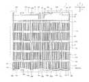
- FIG. 1is a schematic back view of a solar cell module according to an embodiment of the present invention.
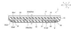
- FIG. 2is a schematic cross-sectional view taken along line II-II in FIG.
- FIG. 3is a schematic rear view of the solar cell in one embodiment of the present invention.
- 4is a schematic cross-sectional view of the solar cell string in the IV portion of FIG.
- FIG. 5is a schematic cross-sectional view of the solar cell string in the V portion of FIG.
- FIG. 6is a schematic rear view of a solar cell module according to a modification.
- the solar cell module 1includes a plurality of solar cell strings 10 each having a plurality of solar cells 20. Specifically, the solar cell module 1 includes first to sixth solar cell strings 10a to 10f. As shown in FIG. 2, the plurality of solar cell strings 10 are arranged between the first protection member 11 and the second protection member 12.
- the first protective member 11is located on the light receiving surface 20 a side of the solar cell 20.
- the second protective member 12is located on the back surface 20 b side of the solar cell 20.
- the second protective member 12has flexibility.
- a sealing material layer 13is provided between the first protective member 11 and the second protective member 12.
- a plurality of solar cells 20are sealed by the sealing material layer 13.
- the first protective member 11can be made of a translucent member such as a glass substrate or a resin substrate, for example.
- the 2nd protection member 12can be constituted by a member which has flexibility, such as a resin sheet and a resin sheet which interposed metal foil, for example.
- the sealing material layer 13can be made of a resin such as ethylene / vinyl acetate copolymer (EVA), polyvinyl butyral (PVB), polyethylene (PE), polyurethane (PU), and the like. It is preferable that the sealing material layer 13 contains a non-crosslinkable resin.
- Each of the plurality of solar cell strings 10is a plurality of solar cells 20 arranged along the x-axis direction that is inclined (typically perpendicular) to the y-axis direction that is the arrangement direction of the solar cell strings 10.
- the solar cell 20includes a photoelectric conversion unit 23 and first and second electrodes 21 and 22.
- the photoelectric conversion unit 23has first and second main surfaces 23a and 23b.
- the first main surface 23 a of the photoelectric conversion unit 23constitutes the light receiving surface 20 a of the solar cell 20, and the second main surface 23 b constitutes the back surface 20 b of the solar cell 20.
- the photoelectric conversion unit 23is a member that generates carriers such as holes and electrons when receiving light.
- the photoelectric conversion unit 23may generate carriers only when light is received on the first main surface 23a, or not only when light is received on the first main surface 23a, but also on the second main surface 23b.
- a carriermay be generated even when light is received. That is, the solar cell 20 may be a double-sided light receiving solar cell.
- the type of the photoelectric conversion unit 23is not particularly limited.
- the photoelectric conversion unit 23can be configured using, for example, a crystalline silicon substrate.
- a first electrode 21 that collects one of holes and electrons and a second electrode 22 that collects the other of holes and electronsare disposed on the second main surface 23b of the photoelectric conversion unit 23. ing. Therefore, the solar cell 20 is a back junction solar cell.
- each of the first and second electrodes 21 and 22has a comb-like shape.
- the first electrode 21 and the second electrode 22are arranged so as to be interleaved with each other.
- each of the first and second electrodes 21 and 22has a plurality of finger portions 21a and 22a and bus bar portions 21b and 22b.
- Each of the plurality of finger portions 21a and 22aextends along the x-axis direction.
- the plurality of finger portions 21a and 22aare arranged at intervals from each other along the y-axis direction perpendicular to the x-axis direction.
- the plurality of finger portions 21aare electrically connected to the bus bar portion 21b.
- the bus bar portion 21bis arranged on one side (x1 side) in the x-axis direction of the plurality of finger portions 21a.
- the bus bar portion 21 bis provided from the one side end portion in the y axis direction to the other side end portion in the x1 side end portion in the x axis direction of the solar cell 20.
- the plurality of finger portions 22aare electrically connected to the bus bar portion 22b.
- the bus bar portion 22bis arranged on the other side (x2 side) in the x-axis direction of the plurality of finger portions 22a.
- the bus bar portion 22bis provided from the one side end portion in the y axis direction to the other side end portion in the x2 side end portion in the x axis direction of the solar cell 20.
- solar cells 20 adjacent in the x-axis directionare electrically connected by a wiring material 31.
- the first electrode 21 of one solar cell 20 and the second electrode 22 of the other solar cell adjacent to each other in the x-axis directionare electrically connected by the wiring member 31. .
- the wiring material 31is, for example, a flexible printed circuit board (FPC: Flexible) having a metal foil, a laminate of metal foils, a metal foil whose surface is covered with solder, an insulating film, and a wiring arranged on the insulating film. It can be constituted by a printed circuit).
- the metal foil and the wiringcan be made of Ag, Cu, or the like, for example.
- the wiring member 31 and the back surface 20b of the solar cell 20are bonded by an adhesive layer (not shown).
- the adhesive layercan be constituted by, for example, a cured product of a resin adhesive, a cured product of a resin adhesive in which a conductive material is dispersed and mixed, solder, or the like.
- the wiring member 31is bonded to the end of the solar cell 20 in the x-axis direction. Specifically, the wiring member 31 is bonded only to the end of the solar cell 20 in the x-axis direction.
- the first to sixth solar cell strings 10a to 10fare electrically connected by the wiring member 32.
- the solar cell 20E that is positioned and the solar cell 20F that is positioned closest to the x2 side of the sixth solar cell string 10fare electrically connected by a wiring member 32, respectively.
- the wiring member 32electrically connects the first electrode 21 of the solar cells 20A, 20C, and 20E and the second electrode 22 of the solar cells 20B, 20D, and 20F.
- the solar cell 20H located on the most x1 side of the second solar cell string 10b, the solar cell 20I located on the most x1 side of the third solar cell string 10c, and the fourth solar cell stringThe solar cell 20J located on the most x1 side of 10d and the solar cell 20K located on the most x1 side of the fifth solar cell string 10e are also electrically connected by the wiring member 32, respectively.
- the wiring member 32electrically connects the first electrode 21 of the solar cells 20H and 20J and the second electrode 22 of the solar cells 20I and 20K.
- a part of each of the wiring member 32 electrically connected to the solar cells 20H and 20I and the wiring member 32 electrically connected to the solar cells 20J and 20Kconstitutes a first extraction electrode 41. Yes. As shown in FIG. 2, the first extraction electrode 41 is extracted to the outside of the sealing material layer 13, more specifically, to the outside of the solar cell module 1. Specifically, the tip end portion of the first extraction electrode 41 reaches the outside of the second protection member 12.
- the wiring member 32has two wiring members 32a and a wiring member 32b. Each of the two wiring members 32 a is bonded to the solar cell 20 by the adhesive layer 40 and is electrically connected to the first or second electrode 21, 22.
- the wiring member 32belectrically connects the two wiring members 32a.
- the wiring member 32ais arranged so that one end portion in the x-axis direction of the solar cell 20 extends from the y1-side end portion in the y-axis direction perpendicular to the x-axis direction to the y2-side end portion.
- the wiring member 32 ais electrically connected to the solar cell located at the end in the x-axis direction among the plurality of solar cells 20 constituting the solar cell string 10.
- the wiring member 32 ais configured by a flexible printed board having a resin film 51 and wirings 52.
- the resin film 51can be made of, for example, a resin such as polyimide (PI) or polyethylene terephthalate (PET).
- the wiring 52is arranged on the resin film 51.
- the wiring 52is electrically connected to the first or second electrode 21 or 22.
- the wiring 52can be made of, for example, a metal foil made of at least one metal such as Cu or Ag.
- the wiring member 32ahas a first portion 32a1, a second portion 32a2, and a bent portion 32a3.
- the first portion 32a1is configured by one side portion of the wiring member 32a.
- the first portion 32a1is arranged so that the wiring 52 faces the solar cell 20 side.
- the first portion 32a1is bonded to the back surface 20b of the solar cell 20.
- the second portion 32a2is constituted by the other side portion of the wiring member 32a.
- the second portion 32 a 2is arranged so that the wiring 52 faces the side opposite to the solar cell 20.
- At least a part of the second portion 32a2is disposed on the first portion 32a1. That is, at least a part of the second portion 32 a 2 overlaps the first portion 32 a 1 in the z-axis direction that is the thickness direction of the solar cell 20.
- the bent portion 32a3connects the first portion 32a1 and the second portion 32a2.
- the bent portion 32a3has a bent structure.
- the wiring 52faces outward.
- the bent portion 32a3is disposed on the back surface 20b of the solar cell 20. That is, the bent portion 32a3 overlaps the solar cell 20 in the z-axis direction.
- the bent portion 32a3is a portion formed by bending a flat wiring material.
- the wiring member 32bis electrically connected to the wiring 52 of the wiring member 32a in the second portion 32a2. That is, the wiring member 32b electrically connects the second portions 32a2 of the solar cell strings 10 adjacent in the y-axis direction.
- the wiring member 32bis arranged so as to overlap the second portion 32a2 in the x-axis direction.
- the wiring member 32bmay be bonded to the wiring member 32a using a resin adhesive, but in this embodiment, the wiring member 32b is bonded to the wiring member 32a with solder and is electrically connected to the wiring 52 of the wiring member 32a. Yes.
- the wiring member 32bis bonded to a part of the wiring member 32a in the y-axis direction.
- Ratio of the length in the y-axis direction of the portion of the wiring member 32a to which the wiring member 32b is bonded to the length in the y-axis direction of the wiring member 32a((y axis of the portion of the wiring member 32a to which the wiring member 32b is bonded) (Length in the direction) / (length in the y-axis direction of the wiring member 32a)) is preferably 1/10 to 1, and more preferably 1/10 to 1/2.
- the wiring member 32bis made of a metal foil made of at least one kind of metal such as Cu or Ag.
- the thickness of the wiring member 32 bis larger than the thickness of the wiring 52.
- the thickness of the wiring member 32bis preferably twice or more the thickness of the wiring 52, and more preferably five times or more.
- a wiring member 33is electrically connected to each of the electrodes 21.
- the solar cells 20G and 20L and the wiring member 33are bonded by an adhesive layer 40.
- the wiring member 33includes a wiring member 32a and a wiring member 33b.
- the wiring member 32 a constituting a part of the wiring member 33has substantially the same configuration as the wiring member 32 a constituting a part of the wiring member 32.
- the wiring member 32a constituting a part of the wiring member 33is bonded and electrically connected to the second electrode 22 of the solar cell 20G and the first electrode 21 of the solar cell 20L.
- the wiring member 33 bis electrically connected to a wiring member 32 a constituting a part of the wiring member 33.
- a part of the wiring member 33 bconstitutes the extraction electrode 42.
- the extraction electrode 42is extracted outside the sealing material layer 13, more specifically, outside the solar cell module 1.
- the wiring member 33 bis electrically connected to the wiring 52 in the second portion 32 a 2 of the wiring member 32 a constituting a part of the wiring member 33.
- the wiring member 33bmay be bonded to the wiring member 32a using a resin adhesive, but in this embodiment, the wiring member 33b is bonded to the wiring member 32a with solder and is electrically connected to the wiring 52 of the wiring member 32a. Yes.
- the wiring member 33bis bonded to a part of the wiring member 32a in the y-axis direction.
- the wiring member 33bis made of a metal foil made of at least one kind of metal such as Cu or Ag.
- the thickness of the wiring member 33 bis larger than the thickness of the wiring 52.
- the thickness of the wiring member 33bis preferably twice or more the thickness of the wiring 52, and more preferably five times or more.
- An insulating sheet 60is disposed between the wiring members 32 b and 33 b and the extraction electrodes 41 and 42 made of metal foil and the back surface 20 b of the solar cell 20. Thereby, short circuit with wiring material 32b, 33b, extraction electrodes 41 and 42, and electrodes 21 and 22 can be controlled.
- the insulating sheet 60may be composed of, for example, a resin such as PI or PET used as the resin film 51, or a resin such as EVA, PVB, PE, or PU used as the sealing material layer 13. it can.
- the insulating sheet disposed between the wiring members 32 b and 33 b and the solar cell 20 and the insulating sheet disposed between the lead electrodes 41 and 42 and the solar cell 20may be provided separately.
- the thermal expansion coefficient of the wiring boardis different from the thermal expansion coefficient of the solar cell. For this reason, when the entire surface of the back junction solar cell is bonded to the wiring substrate as in the solar cell module described in Patent Document 1, the wiring substrate and the solar cell are easily peeled off.
- the wiring member 31is bonded to the end of the solar cell 20 in the x-axis direction and is not bonded to the entire surface of the solar cell 20. For this reason, even if the temperature of the solar cell module 1 changes, it is difficult to apply a large stress between the wiring member 31 and the solar cell 20. Therefore, the wiring material 31 and the solar cell 20 are difficult to peel off.
- the wiring member 32ais electrically connected to the solar cell 20 at the end of the solar cell 20 in the x-axis direction.
- the 2nd part 32a2 of the wiring material 32a of the solar cell string 10 adjacent in a y-axis directionis electrically connected by the wiring material 32b which consists of metal foil.
- An insulating sheet 60is disposed between the wiring member 32 b and the solar cell 20. The insulating sheet 60 insulates the wiring member 32b and the solar cell 20 from each other.
- the insulating sheet 60is provided not only in the region where the wiring member 32b is provided, but also in the region where the wiring member 32a is provided. For this reason, the connection reliability of the wiring material 32a and the wiring material 32b can be improved, maintaining the insulation between the wiring material 32b and the solar cell 20.
- the insulating sheet 60can be made small by adopting the configuration as described above.
- the wiring member 32bis provided so as to overlap the second portion 32a2 in the x-axis direction. For this reason, the length in the x-axis direction of the region where the second portion 32a2 and the wiring member 32b are provided can be shortened. For this reason, the insulating sheet 60 can be made smaller. Therefore, the manufacturing cost of the solar cell module 1 can be reduced as much as the expensive insulating sheet 60 can be reduced.
- the length along the x-axis direction of the second portion 32a2 of the solar cell strings 10a and 10f located outside in the y-axis direction and the center side in the y-axis directionare positioned.
- the length of the second portion 32a2 in the solar cell strings 10b to 10e along the x-axis directionis the same.
- the plurality of solar cell strings 10include the solar cell strings 10 having different lengths along the x-axis direction of the second portion 32 a 2.
- the length along the x-axis direction of the second portion 32a2 of the solar cell strings 10a and 10f located outside in the y-axis directionis the sun located on the center side in the y-axis direction. It is longer than the length along the x-axis direction of the second portion 32a2 in the battery strings 10b to 10e.
- the extraction electrode 42is electrically connected in the relatively long second portion 32a2 of the solar cell strings 10b to 10e.
- a portion of the extraction electrode 42 on the second portion 32a2 sideextends from the second portion 32a2 along the y-axis direction.
- the solar cell module 2unlike the solar cell module 1, in the solar cell module 2, it is not necessary to provide a bent part in the part of the extraction electrode 42 on the second part 32a2 side. Therefore, the production cost of the extraction electrode 42 is reduced. Therefore, the manufacturing cost of the solar cell module 2 can be reduced.
- the first and second electrodesmay be bus bar-less electrodes that do not have a bus bar portion and are configured by a plurality of finger portions.
- the solar cell modulemay include only one solar cell.
Landscapes
- Photovoltaic Devices (AREA)
- Life Sciences & Earth Sciences (AREA)
- Engineering & Computer Science (AREA)
- Sustainable Development (AREA)
- Sustainable Energy (AREA)
Abstract
Description
Translated fromJapanese本発明は太陽電池モジュールに関する。The present invention relates to a solar cell module.
従来、改善された光電変換効率を有する太陽電池モジュールとして、裏面接合型の太陽電池を有する太陽電池モジュールが知られている。例えば特許文献1には、その一例が記載されている。特許文献1に記載の太陽電池モジュールは、表面に配線が設けられた配線基板を複数備えている。配線基板上には、一の方向に沿って配列された複数の裏面接合型の太陽電池が配置されている。複数の太陽電池は、配線基板の配線に電気的に接続されている。複数の配線基板は、一の方向に対して垂直な他の方向に沿って配されている。他の方向において隣り合う配線基板同士は、導電性部材によって電気的に接続されている。Conventionally, a solar cell module having a back junction type solar cell is known as a solar cell module having improved photoelectric conversion efficiency. For example,
近年、太陽電池モジュールの耐久性をさらに改善したいという要望が高まってきている。In recent years, there has been an increasing demand for further improving the durability of solar cell modules.
本発明は、改善された耐久性を有する太陽電池モジュールを提供することを主な目的とする。The main object of the present invention is to provide a solar cell module having improved durability.
本発明に係る太陽電池モジュールは、複数の太陽電池ストリングと、第1の配線材とを備える。複数の太陽電池ストリングは、一の方向に沿って配されている。第1の配線材は、隣り合う太陽電池ストリング同士を電気的に接続している。第1の配線材は、金属箔からなる。太陽電池ストリングは、複数の太陽電池と、第2の配線材と、第3の配線材とを有する。複数の太陽電池は、一の方向に対して傾斜した他の方向に沿って配されている。第2の配線材は、隣り合う太陽電池のそれぞれの端部に接着されている。第2の配線材は、隣り合う太陽電池同士を電気的に接続している。第3の配線材は、複数の太陽電池のうち、他の方向における最も端部に位置する太陽電池の他の方向における端部において当該太陽電池にに電気的に接続されている。第3の配線材は、樹脂フィルム及び樹脂フィルムの上に配された金属箔を有する。第3の配線材は、第1の部分と、第2の部分と、第3の部分とを含む。第1の部分では、金属箔が太陽電池側を向いている。第1の部分は、太陽電池に電気的に接続されている。第2の部分は、金属箔が太陽電池とは反対側を向くように太陽電池の上に配されている。第3の部分は、第1の部分と第2の部分とを接続している。第1の配線材は、隣り合う太陽電池ストリングの第2の部分同士を電気的に接続している。本発明に係る太陽電池モジュールは、絶縁性シートをさらに備える。絶縁性シートは、第1の配線材と太陽電池との間に配されている。The solar cell module according to the present invention includes a plurality of solar cell strings and a first wiring material. The plurality of solar cell strings are arranged along one direction. The first wiring member electrically connects adjacent solar cell strings. The first wiring material is made of a metal foil. The solar cell string includes a plurality of solar cells, a second wiring material, and a third wiring material. The plurality of solar cells are arranged along another direction inclined with respect to one direction. The 2nd wiring material is adhere | attached on each edge part of an adjacent solar cell. The second wiring member electrically connects adjacent solar cells. The 3rd wiring material is electrically connected to the said solar cell in the edge part in the other direction of the solar cell located in the most edge part in another direction among several solar cells. The third wiring member has a resin film and a metal foil disposed on the resin film. The third wiring member includes a first portion, a second portion, and a third portion. In the first part, the metal foil faces the solar cell side. The first part is electrically connected to the solar cell. The second portion is arranged on the solar cell so that the metal foil faces the side opposite to the solar cell. The third part connects the first part and the second part. The first wiring member electrically connects the second portions of the adjacent solar cell strings. The solar cell module according to the present invention further includes an insulating sheet. The insulating sheet is disposed between the first wiring member and the solar cell.
本発明によれば、改善された耐久性を有する太陽電池モジュールを提供することができる。According to the present invention, a solar cell module having improved durability can be provided.
以下、本発明を実施した好ましい形態の一例について説明する。但し、下記の実施形態は、単なる例示である。本発明は、下記の実施形態に何ら限定されない。Hereinafter, an example of a preferable embodiment in which the present invention is implemented will be described. However, the following embodiment is merely an example. The present invention is not limited to the following embodiments.
また、実施形態等において参照する各図面において、実質的に同一の機能を有する部材は同一の符号で参照することとする。また、実施形態等において参照する図面は、模式的に記載されたものであり、図面に描画された物体の寸法の比率などは、現実の物体の寸法の比率などとは異なる場合がある。図面相互間においても、物体の寸法比率等が異なる場合がある。具体的な物体の寸法比率等は、以下の説明を参酌して判断されるべきである。In each drawing referred to in the embodiment and the like, members having substantially the same function are referred to by the same reference numerals. The drawings referred to in the embodiments and the like are schematically described, and the ratio of the dimensions of the objects drawn in the drawings may be different from the ratio of the dimensions of the actual objects. The dimensional ratio of the object may be different between the drawings. The specific dimensional ratio of the object should be determined in consideration of the following description.
図1及び図2に示されるように、太陽電池モジュール1は、それぞれ複数の太陽電池20を有する複数の太陽電池ストリング10を備えている。具体的には、太陽電池モジュール1は、第1~第6の太陽電池ストリング10a~10fを備えている。図2に示されるように、複数の太陽電池ストリング10は、第1の保護部材11と、第2の保護部材12との間に配されている。第1の保護部材11は、太陽電池20の受光面20a側に位置している。第2の保護部材12は、太陽電池20の裏面20b側に位置している。第2の保護部材12は、可撓性を有する。第1の保護部材11と第2の保護部材12との間には封止材層13が設けられている。この封止材層13により複数の太陽電池20が封止されている。1 and 2, the
第1の保護部材11は、例えば、ガラス基板、樹脂基板等の透光性を有する部材により構成することができる。第2の保護部材12は、例えば、樹脂シート、金属箔を介在させた樹脂シート等の可撓性を有する部材により構成することができる。封止材層13は、例えば、エチレン・酢酸ビニル共重合体(EVA)、ポリビニルブチラール(PVB)、ポリエチレン(PE)、ポリウレタン(PU)などの樹脂により構成することができる。封止材層13は、非架橋性樹脂を含むことが好ましい。The first
複数の太陽電池ストリング10のそれぞれは、太陽電池ストリング10の配列方向であるy軸方向に対して傾斜した(典型的には、垂直な)x軸方向に沿って配された複数の太陽電池20を有する。図1及び図3に示されるように、太陽電池20は、光電変換部23と、第1及び第2の電極21,22とを有する。Each of the plurality of
光電変換部23は、第1及び第2の主面23a、23bを有する。光電変換部23の第1の主面23aが太陽電池20の受光面20aを構成しており、第2の主面23bが太陽電池20の裏面20bを構成している。The
光電変換部23は、受光した際に正孔や電子などのキャリアを生成させる部材である。光電変換部23は、第1の主面23aにおいて受光したときのみキャリアを生成させるものであってもよいし、第1の主面23aにおいて受光したときのみならず、第2の主面23bにおいて受光したときにもキャリアを発生させるものであってもよい。即ち、太陽電池20は、両面受光型の太陽電池であってもよい。The
なお、光電変換部23の種類は特に限定されない。光電変換部23は、例えば、結晶シリコン基板等を用いて構成することができる。Note that the type of the
光電変換部23の第2の主面23bの上には、正孔及び電子の一方を収集する第1の電極21と、正孔及び電子の他方を収集する第2の電極22とが配されている。従って、太陽電池20は、裏面接合型の太陽電池である。A
第1及び第2の電極21,22のそれぞれの形状は特に限定されない。本実施形態では、第1及び第2の電極21,22のそれぞれは、くし歯状の形状を有する。第1の電極21と第2の電極22とは、互いに間挿し合うように配されている。具体的には、第1及び第2の電極21,22のそれぞれは、複数のフィンガー部21a、22aと、バスバー部21b、22bとを有する。複数のフィンガー部21a、22aのそれぞれは、x軸方向に沿って延びている。複数のフィンガー部21a、22aは、x軸方向に対して垂直なy軸方向に沿って相互に間隔をおいて配されている。The shape of each of the first and
複数のフィンガー部21aは、バスバー部21bに電気的に接続されている。バスバー部21bは、複数のフィンガー部21aのx軸方向における一方側(x1側)に配されている。バスバー部21bは、太陽電池20のx軸方向におけるx1側端部において、y軸方向の一方側端部から他方側端部にわたって設けられている。The plurality of
同様に、複数のフィンガー部22aは、バスバー部22bに電気的に接続されている。バスバー部22bは、複数のフィンガー部22aのx軸方向における他方側(x2側)に配されている。バスバー部22bは、太陽電池20のx軸方向におけるx2側端部において、y軸方向の一方側端部から他方側端部にわたって設けられている。Similarly, the plurality of
図1に示されるように、複数の太陽電池ストリング10のそれぞれにおいて、x軸方向において隣り合う太陽電池20は、配線材31によって電気的に接続されている。具体的には、x軸方向において隣接する太陽電池20の一方の太陽電池20の第1の電極21と他方の太陽電池の第2の電極22とが配線材31によって電気的に接続されている。As shown in FIG. 1, in each of the plurality of solar cell strings 10,
配線材31は、例えば、金属箔、金属箔の積層体、表面が半田等で覆われた金属箔、絶縁性フィルム及び絶縁性フィルム上に配された配線とを有するフレキシブルプリント基板(FPC:Flexible Printed Circuit)などにより構成することができる。金属箔および配線は、例えば、Ag、Cu等により構成することができる。The
配線材31と太陽電池20の裏面20bとは、図示しない接着層によって接着されている。接着層は、例えば、樹脂接着剤の硬化物、導電材が分散混入している樹脂接着剤の硬化物、半田等により構成することができる。配線材31は、太陽電池20のx軸方向における端部に接着されている。具体的には、配線材31は、太陽電池20のx軸方向における端部にのみ接着されている。The
第1~第6の太陽電池ストリング10a~10fは、配線材32により電気的に接続されている。具体的には、第1の太陽電池ストリング10aの最もx2側に位置している太陽電池20Aと第2の太陽電池ストリング10bの最もx2側に位置している太陽電池20Bと、第3の太陽電池ストリング10cの最もx2側に位置している太陽電池20Cと第4の太陽電池ストリング10dの最もx2側に位置している太陽電池20Dと、及び第5の太陽電池ストリング10eの最もx2側に位置している太陽電池20Eと第6の太陽電池ストリング10fの最もx2側に位置している太陽電池20Fとは、それぞれ、配線材32によって電気的に接続されている。配線材32は、太陽電池20A,20C,20Eの第1の電極21と、太陽電池20B,20D,20Fの第2の電極22とを電気的に接続している。The first to sixth
また、第2の太陽電池ストリング10bの最もx1側に位置している太陽電池20Hと第3の太陽電池ストリング10cの最もx1側に位置している太陽電池20Iと、及び第4の太陽電池ストリング10dの最もx1側に位置している太陽電池20Jと第5の太陽電池ストリング10eの最もx1側に位置している太陽電池20Kとも、それぞれ、配線材32によって電気的に接続されている。配線材32は、太陽電池20H,20Jの第1の電極21と、太陽電池20I,20Kの第2の電極22とを電気的に接続している。In addition, the
太陽電池20H,20Iに電気的に接続された配線材32と、太陽電池20J,20Kに電気的に接続された配線材32とのそれぞれの一部は、第1の引き出し電極41を構成している。図2に示されるように、第1の引き出し電極41は、封止材層13の外側、より具体的には、太陽電池モジュール1の外部に引き出されている。具体的には、第1の引き出し電極41の先端部は、第2の保護部材12の外側に至っている。A part of each of the
配線材32は、2つの配線材32aと、配線材32bとを有する。2つの配線材32aのそれぞれは、接着層40により太陽電池20に接着されており、第1または第2の電極21,22に電気的に接続されている。配線材32bは、2つの配線材32aを電気的に接続している。配線材32aは、太陽電池20のx軸方向における一の端部の、x軸方向に対して垂直なy軸方向のy1側端部からy2側端部に至るように配されている。配線材32aは、太陽電池ストリング10を構成している複数の太陽電池20のうち、x軸方向における最も端部に位置する太陽電池に電気的に接続されている。The
図4に示されるように、配線材32aは、樹脂フィルム51と、配線52とを有するフレキシブルプリント基板により構成されている。樹脂フィルム51は、例えば、ポリイミド(PI)や、ポリエチレンテレフタレート(PET)などの樹脂により構成することができる。配線52は、樹脂フィルム51の上に配されている。配線52は、第1または第2の電極21,22と電気的に接続されている。配線52は、例えば、CuやAgなどの少なくとも一種の金属からなる金属箔により構成することができる。As shown in FIG. 4, the
配線材32aは、第1の部分32a1と、第2の部分32a2と、屈曲部32a3とを有する。第1の部分32a1は、配線材32aの一方側部分により構成されている。第1の部分32a1は、配線52が太陽電池20側を向くように配されている。第1の部分32a1は、太陽電池20の裏面20bに接着されている。The
第2の部分32a2は、配線材32aの他方側部分により構成されている。第2の部分32a2は、配線52が太陽電池20とは反対側を向くように配されている。第2の部分32a2の少なくとも一部は、第1の部分32a1の上に配されている。即ち、第2の部分32a2の少なくとも一部は、第1の部分32a1と太陽電池20の厚み方向であるz軸方向において重なっている。The second portion 32a2 is constituted by the other side portion of the
屈曲部32a3は、第1の部分32a1と第2の部分32a2とを接続している。屈曲部32a3は、屈曲構造を有する。屈曲部32a3では、配線52が外側を向いている。屈曲部32a3は、太陽電池20の裏面20bの上に配されている。即ち、屈曲部32a3は、太陽電池20とz軸方向において重なっている。屈曲部32a3は、平板状の配線材が折り曲げられることにより形成された部分である。The bent portion 32a3 connects the first portion 32a1 and the second portion 32a2. The bent portion 32a3 has a bent structure. In the bent portion 32a3, the
配線材32bは、第2の部分32a2において配線材32aの配線52に電気的に接続されている。すなわち、配線材32bは、y軸方向において隣り合う太陽電池ストリング10の第2の部分32a2同士を電気的に接続している。配線材32bは、x軸方向において、第2の部分32a2と重なるように配されている。配線材32bは、樹脂接着剤を用いて配線材32aに接着されていてもよいが、本実施形態では半田により配線材32aに接着されると共に配線材32aの配線52に電気的に接続されている。配線材32bは、配線材32aのy軸方向における一部分に接着されている。配線材32aのy軸方向における長さに対する、配線材32aの配線材32bが接着された部分のy軸方向における長さの比((配線材32aの配線材32bが接着された部分のy軸方向における長さ)/(配線材32aのy軸方向における長さ))は、1/10~1であることが好ましく、1/10~1/2であることがより好ましい。The
なお、配線材32bの一部は、引き出し電極41を構成しており、太陽電池モジュール1外に引き出されている。Note that a part of the
本実施形態において、配線材32bは、CuやAgなどの少なくとも一種の金属からなる金属箔により構成されている。配線材32bの厚みは、配線52の厚みよりも大きい。配線材32bの厚みは、配線52の厚みの2倍以上であることが好ましく、5倍以上であることがより好ましい。In the present embodiment, the
第1の太陽電池ストリング10aの最もx1側に位置している太陽電池20Gの第2の電極22と、第6の太陽電池ストリング10fの最もx1側に位置している太陽電池20Lの第1の電極21とのそれぞれには、配線材33が電気的に接続されている。太陽電池20G,20Lと配線材33とは接着層40により接着されている。The
配線材33は、配線材32aと、配線材33bとを有する。配線材33の一部を構成している配線材32aは、配線材32の一部を構成している配線材32aと実質的に同様の構成を有する。配線材33の一部を構成している配線材32aは、太陽電池20Gの第2の電極22及び太陽電池20Lの第1の電極21に接着され、電気的に接続されている。The
配線材33bは、配線材33の一部を構成している配線材32aに電気的に接続されている。配線材33bの一部は、引き出し電極42を構成している。引き出し電極42は、封止材層13の外側、より具体的には、太陽電池モジュール1外に引き出されている。The
配線材33bは、配線材33の一部を構成している配線材32aの第2の部分32a2において配線52に電気的に接続されている。配線材33bは、樹脂接着剤を用いて配線材32aに接着されていてもよいが、本実施形態では半田により配線材32aに接着されると共に配線材32aの配線52に電気的に接続されている。配線材33bは、配線材32aのy軸方向における一部分に接着されている。The
本実施形態において、配線材33bは、CuやAgなどの少なくとも一種の金属からなる金属箔により構成されている。配線材33bの厚みは、配線52の厚みよりも大きい。配線材33bの厚みは、配線52の厚みの2倍以上であることが好ましく、5倍以上であることがより好ましい。In the present embodiment, the
金属箔により構成されている配線材32b、33b、引き出し電極41,42と、太陽電池20の裏面20bとの間には、絶縁性シート60が配されている。これにより、配線材32b、33b、引き出し電極41,42と電極21,22との短絡を抑制することができる。なお、絶縁性シート60は、例えば、樹脂フィルム51として用いられるPIや、PETなどの樹脂の他、封止材層13として用いられるEVA、PVB、PE、PUなどの樹脂などにより構成することができる。配線材32b、33bと太陽電池20との間に配された絶縁性シートと、引き出し電極41,42と太陽電池20との間に配された絶縁性シートとを別体に設けてもよい。An insulating
ところで、配線基板の熱膨張係数は、太陽電池の熱膨張係数とは異なる。このため、特許文献1に記載の太陽電池モジュールのように、裏面接合型の太陽電池の全面が配線基板に接着されている場合は、配線基板と太陽電池とが剥離しやすい。By the way, the thermal expansion coefficient of the wiring board is different from the thermal expansion coefficient of the solar cell. For this reason, when the entire surface of the back junction solar cell is bonded to the wiring substrate as in the solar cell module described in
一方、太陽電池モジュール1では、配線材31は、太陽電池20のx軸方向における端部に接着されており、太陽電池20の全面に接着されていない。このため、太陽電池モジュール1の温度が変化した場合であっても、配線材31と太陽電池20との間に大きな応力が加わり難い。よって、配線材31と太陽電池20とが剥離しにくい。On the other hand, in the
同様に、配線材32aが太陽電池20のx軸方向における端部において、当該太陽電池20に電気的に接続されている。そして、y軸方向において隣り合う太陽電池ストリング10の配線材32aの第2の部分32a2同士が、金属箔からなる配線材32bによって電気的に接続されている。配線材32bと太陽電池20との間には、絶縁性シート60が配されている。この絶縁性シート60によって配線材32bと太陽電池20とが絶縁されている。このような構成を採用することによって、太陽電池モジュール1の温度が変化した場合であっても、配線材32bと太陽電池20との間に大きな応力が加わり難い。よって、配線材32bと太陽電池20とが剥離しにくい。従って、改善された耐久性を有する太陽電池モジュール1を実現することができる。Similarly, the
ところで、2つの配線材32aを配線材32bで接続する構成とした場合、配線材32bの一部が太陽電池20の第1の電極21または第2の電極22と接触する可能性がある。接触による電流リークを防止するために、配線材32bと太陽電池20との間にのみ絶縁性シートを設けることが考えられる。しかし、この部分にのみ絶縁性シートを設けた場合、配線材32aが設けられる領域と、配線材32bが設けられる領域とで段差が生じ、配線材32aに接続された配線材32bが外れてしまう虞がある。このような状況は、例えば、複数の太陽電池20を封止材層13の中に封止する工程において発生する可能性がある。By the way, when it is set as the structure which connects the two
本実施形態では、配線材32bが設けられた領域のみならず、配線材32aが設けられた領域にも、絶縁シート60を設けられている。このため、配線材32bと太陽電池20との絶縁性を保ちつつ、配線材32aと配線材32bとの接続信頼性を高めることができる。In the present embodiment, the insulating
また、上記のような構成を採用することにより、絶縁性シート60を小さくし得る。特に、太陽電池モジュール1では、配線材32bがx軸方向において第2の部分32a2と重なるように設けられている。このため、第2の部分32a2及び配線材32bが設けられた領域のx軸方向における長さを短くすることができる。このため、絶縁性シート60をより小さくし得る。従って、高価な絶縁性シート60を小さくし得る分、太陽電池モジュール1の製造コストを低減することができる。Moreover, the insulating
なお、太陽電池モジュール1では、y軸方向における外側に位置している太陽電池ストリング10a、10fにおける第2の部分32a2のx軸方向に沿った長さと、y軸方向における中央側に位置している太陽電池ストリング10b~10eにおける第2の部分32a2のx軸方向に沿った長さとが同じである。一方、図6に示されるように、太陽電池モジュール2では、複数の太陽電池ストリング10が、第2の部分32a2のx軸方向に沿った長さが異なる太陽電池ストリング10を含む。具体的には、y軸方向における外側に位置している太陽電池ストリング10a、10fにおける第2の部分32a2のx軸方向に沿った長さが、y軸方向における中央側に位置している太陽電池ストリング10b~10eにおける第2の部分32a2のx軸方向に沿った長さよりも長い。太陽電池ストリング10b~10eの相対的に長い第2の部分32a2には、太陽電池ストリング10a、10fの相対的に短い第2の部分32a2よりも太陽電池モジュール2の中央寄りに位置する部分において、引き出し電極42が電気的に接続されている。引き出し電極42の第2の部分32a2側の部分は、第2の部分32a2からy軸方向に沿って延びている。このため、太陽電池モジュール1とは異なり、太陽電池モジュール2では、引き出し電極42の第2の部分32a2側の部分に折れ曲がり部を設ける必要がない。よって、引き出し電極42の作製費用が低くなる。従って、太陽電池モジュール2の製造コストを低減することができる。In the
本発明はここでは記載していない様々な実施形態を含む。例えば、第1及び第2の電極は、バスバー部を有さず、複数のフィンガー部により構成されているバスバーレスの電極であってもよい。The present invention includes various embodiments not described herein. For example, the first and second electrodes may be bus bar-less electrodes that do not have a bus bar portion and are configured by a plurality of finger portions.
太陽電池モジュールは、ひとつの太陽電池のみを備えていてもよい。The solar cell module may include only one solar cell.
以上のように、本発明はここでは記載していない様々な実施形態を含む。従って、本発明の技術的範囲は上記の説明から妥当な特許請求の範囲に係る発明特定事項によってのみ定められるものである。As described above, the present invention includes various embodiments not described herein. Therefore, the technical scope of the present invention is defined only by the invention specifying matters according to the scope of claims reasonable from the above description.
1…太陽電池モジュール
10,10a~10f…太陽電池ストリング
11…第1の保護部材
12…第2の保護部材
13…封止材層
20,20A~20L…太陽電池
20a…受光面
20b…裏面
21…第1の電極
22…第2の電極
23…光電変換部
31~33,32a、32b、33b…配線材
32a1…第1の部分
32a2…第2の部分
32a3…屈曲部
51…樹脂フィルム
52…配線
60…絶縁性シート
DESCRIPTION OF
Claims (4)
Translated fromJapanese隣り合う前記太陽電池ストリング同士を電気的に接続しており、金属箔からなる第1の配線材と、
を備え、
前記太陽電池ストリングは、
一の方向に対して傾斜した他の方向に沿って配された複数の太陽電池と、
隣り合う前記太陽電池のそれぞれの端部に接着されており、前記隣り合う太陽電池同士を電気的に接続している第2の配線材と、
前記複数の太陽電池のうち、前記他の方向における最も端部に位置する太陽電池の他の方向における端部において当該太陽電池に電気的に接続されており、樹脂フィルム及び前記樹脂フィルムの上に配された金属箔を有する第3の配線材と、
を有し、
第3の配線材は、
前記金属箔が前記太陽電池側を向いており、前記太陽電池に電気的に接続された第1の部分と、
前記金属箔が前記太陽電池とは反対側を向くように前記太陽電池の上に配された第2の部分と、
前記第1の部分と前記第2の部分とを接続している第3の部分と、
を含み、
前記第1の配線材は、前記隣り合う太陽電池ストリングの第2の部分同士を電気的に接続しており、
前記第1の配線材と前記太陽電池との間に配された絶縁性シートをさらに備える、太陽電池モジュール。A plurality of solar cell strings arranged along one direction;
The adjacent solar cell strings are electrically connected to each other, and a first wiring member made of metal foil,
With
The solar cell string is
A plurality of solar cells arranged along another direction inclined with respect to one direction;
A second wiring member that is bonded to each end of the adjacent solar cells and electrically connects the adjacent solar cells;
Of the plurality of solar cells, the solar cell is electrically connected to the solar cell at the end portion in the other direction of the solar cell located at the end in the other direction, and is on the resin film and the resin film. A third wiring member having a disposed metal foil;
Have
The third wiring material is
The metal foil faces the solar cell side, and a first portion electrically connected to the solar cell;
A second portion disposed on the solar cell such that the metal foil faces away from the solar cell;
A third portion connecting the first portion and the second portion;
Including
The first wiring member electrically connects the second portions of the adjacent solar cell strings,
The solar cell module further provided with the insulating sheet distribute | arranged between the said 1st wiring material and the said solar cell.
前記第3の部分に電気的に接続されており、前記封止材の外部にまで引き出された引き出し電極と、
をさらに備え、
前記引き出し電極と前記太陽電池との間に配された絶縁性シートを備える、請求項1または2に記載の太陽電池モジュール。A sealing material for sealing the solar cell string and the first to third wiring materials;
An extraction electrode that is electrically connected to the third portion and is extracted to the outside of the sealing material;
Further comprising
The solar cell module of Claim 1 or 2 provided with the insulating sheet distribute | arranged between the said extraction electrode and the said solar cell.
前記相対的に長い第2の部分の前記相対的に短い第2の部分よりも前記太陽電池モジュールの中央寄りに位置する部分に前記引き出し電極が接続されており、当該引き出し電極は、前記相対的に長い第2の部分から前記一の方向に沿って延びる部分を有する、請求項3に記載の太陽電池モジュール。The plurality of solar cell strings include solar cell strings having different lengths along the other direction of the second portion,
The extraction electrode is connected to a portion of the relatively long second portion located closer to the center of the solar cell module than the relatively short second portion, and the extraction electrode is The solar cell module according to claim 3, further comprising a portion extending along the one direction from a long second portion.
Priority Applications (4)
| Application Number | Priority Date | Filing Date | Title |
|---|---|---|---|
| JP2013535968AJP6152796B2 (en) | 2011-09-29 | 2012-05-25 | Solar cell module |
| EP12837450.1AEP2763187B1 (en) | 2011-09-29 | 2012-05-25 | Solar cell module |
| US14/221,977US9490383B2 (en) | 2011-09-29 | 2014-03-21 | Solar module |
| US15/285,455US20170084767A1 (en) | 2011-09-29 | 2016-10-04 | Solar module |
Applications Claiming Priority (2)
| Application Number | Priority Date | Filing Date | Title |
|---|---|---|---|
| JP2011-213704 | 2011-09-29 | ||
| JP2011213704 | 2011-09-29 |
Related Child Applications (1)
| Application Number | Title | Priority Date | Filing Date |
|---|---|---|---|
| US14/221,977ContinuationUS9490383B2 (en) | 2011-09-29 | 2014-03-21 | Solar module |
Publications (1)
| Publication Number | Publication Date |
|---|---|
| WO2013046801A1true WO2013046801A1 (en) | 2013-04-04 |
Family
ID=47994842
Family Applications (2)
| Application Number | Title | Priority Date | Filing Date |
|---|---|---|---|
| PCT/JP2012/059629WO2013046773A1 (en) | 2011-09-29 | 2012-04-09 | Solar cell module |
| PCT/JP2012/063502WO2013046801A1 (en) | 2011-09-29 | 2012-05-25 | Solar cell module |
Family Applications Before (1)
| Application Number | Title | Priority Date | Filing Date |
|---|---|---|---|
| PCT/JP2012/059629WO2013046773A1 (en) | 2011-09-29 | 2012-04-09 | Solar cell module |
Country Status (5)
| Country | Link |
|---|---|
| US (3) | US20140202518A1 (en) |
| EP (2) | EP2763188A4 (en) |
| JP (3) | JPWO2013046773A1 (en) |
| MY (1) | MY170844A (en) |
| WO (2) | WO2013046773A1 (en) |
Cited By (2)
| Publication number | Priority date | Publication date | Assignee | Title |
|---|---|---|---|---|
| CN105850034A (en)* | 2013-12-27 | 2016-08-10 | 松下知识产权经营株式会社 | Solar cell module |
| JP2018142747A (en)* | 2015-03-31 | 2018-09-13 | パナソニックIpマネジメント株式会社 | Solar battery module |
Families Citing this family (6)
| Publication number | Priority date | Publication date | Assignee | Title |
|---|---|---|---|---|
| US9666739B2 (en)* | 2013-06-28 | 2017-05-30 | Sunpower Corporation | Photovoltaic cell and laminate metallization |
| JP6373911B2 (en) | 2016-08-23 | 2018-08-15 | 株式会社豊田自動織機 | Solar cell module |
| JP6793313B2 (en)* | 2016-12-22 | 2020-12-02 | パナソニックIpマネジメント株式会社 | Solar cell module |
| US20190288638A1 (en)* | 2018-03-15 | 2019-09-19 | The Boeing Company | Rollable solar power module with high packing density |
| US11257969B2 (en) | 2018-03-15 | 2022-02-22 | The Boeing Company | Blocking diode board for rollable solar power module |
| US12283640B2 (en) | 2023-04-07 | 2025-04-22 | The Boeing Company | Bypass diode assemblies for a solar cell array |
Citations (4)
| Publication number | Priority date | Publication date | Assignee | Title |
|---|---|---|---|---|
| JP2005011869A (en)* | 2003-06-17 | 2005-01-13 | Sekisui Jushi Co Ltd | Solar cell module and its manufacturing method |
| JP2007294866A (en)* | 2006-03-31 | 2007-11-08 | Sanyo Electric Co Ltd | Solar cell module |
| JP2009043842A (en)* | 2007-08-07 | 2009-02-26 | Sharp Corp | Solar cell module |
| JP2009224598A (en)* | 2008-03-17 | 2009-10-01 | Sharp Corp | Solar cell module, and manufacturing method of solar cell module |
Family Cites Families (14)
| Publication number | Priority date | Publication date | Assignee | Title |
|---|---|---|---|---|
| JPS60123073A (en)* | 1983-12-08 | 1985-07-01 | Fuji Electric Corp Res & Dev Ltd | thin film solar cells |
| JPH06310744A (en)* | 1993-04-26 | 1994-11-04 | Fuji Electric Co Ltd | Thin film solar cell module and connection method thereof |
| JP4817619B2 (en)* | 2004-06-30 | 2011-11-16 | 京セラ株式会社 | Solar cell module |
| US20070295381A1 (en)* | 2004-03-29 | 2007-12-27 | Kyocera Corporation | Solar Cell Module and Photovoltaic Power Generator Using This |
| JP5355087B2 (en)* | 2006-07-31 | 2013-11-27 | 三井化学株式会社 | Solar cell sealing thermoplastic resin composition, solar cell sealing sheet, and solar cell |
| WO2008078741A1 (en)* | 2006-12-26 | 2008-07-03 | Kyocera Corporation | Solar cell module |
| US20090139557A1 (en)* | 2007-11-30 | 2009-06-04 | Douglas Rose | Busbar connection configuration to accommodate for cell misalignment |
| CN101984772A (en)* | 2008-03-17 | 2011-03-09 | 夏普株式会社 | Solar cell module and method for manufacturing solar cell module |
| JP5004835B2 (en)* | 2008-03-17 | 2012-08-22 | シャープ株式会社 | Solar cell module and method for manufacturing solar cell module |
| JP4838827B2 (en)* | 2008-07-02 | 2011-12-14 | シャープ株式会社 | Solar cell module and manufacturing method thereof |
| JP5203176B2 (en)* | 2008-12-26 | 2013-06-05 | シャープ株式会社 | Wiring sheet, solar cell with wiring sheet and solar cell module |
| JP2011054662A (en)* | 2009-08-31 | 2011-03-17 | Sanyo Electric Co Ltd | Solar cell module |
| JP5642370B2 (en)* | 2009-09-29 | 2014-12-17 | 三洋電機株式会社 | Solar cell module |
| KR100990116B1 (en)* | 2010-05-17 | 2010-10-29 | 엘지전자 주식회사 | Solar cell module |
- 2012
- 2012-04-09WOPCT/JP2012/059629patent/WO2013046773A1/enactiveApplication Filing
- 2012-04-09EPEP12837549.0Apatent/EP2763188A4/ennot_activeWithdrawn
- 2012-04-09JPJP2013535959Apatent/JPWO2013046773A1/ennot_activeWithdrawn
- 2012-05-25EPEP12837450.1Apatent/EP2763187B1/enactiveActive
- 2012-05-25WOPCT/JP2012/063502patent/WO2013046801A1/enactiveApplication Filing
- 2012-05-25JPJP2013535968Apatent/JP6152796B2/ennot_activeExpired - Fee Related
- 2012-05-25MYMYPI2014700757Apatent/MY170844A/enunknown
- 2014
- 2014-03-21USUS14/222,043patent/US20140202518A1/ennot_activeAbandoned
- 2014-03-21USUS14/221,977patent/US9490383B2/ennot_activeExpired - Fee Related
- 2016
- 2016-10-04USUS15/285,455patent/US20170084767A1/ennot_activeAbandoned
- 2017
- 2017-01-05JPJP2017000782Apatent/JP6341437B2/ennot_activeExpired - Fee Related
Patent Citations (4)
| Publication number | Priority date | Publication date | Assignee | Title |
|---|---|---|---|---|
| JP2005011869A (en)* | 2003-06-17 | 2005-01-13 | Sekisui Jushi Co Ltd | Solar cell module and its manufacturing method |
| JP2007294866A (en)* | 2006-03-31 | 2007-11-08 | Sanyo Electric Co Ltd | Solar cell module |
| JP2009043842A (en)* | 2007-08-07 | 2009-02-26 | Sharp Corp | Solar cell module |
| JP2009224598A (en)* | 2008-03-17 | 2009-10-01 | Sharp Corp | Solar cell module, and manufacturing method of solar cell module |
Cited By (2)
| Publication number | Priority date | Publication date | Assignee | Title |
|---|---|---|---|---|
| CN105850034A (en)* | 2013-12-27 | 2016-08-10 | 松下知识产权经营株式会社 | Solar cell module |
| JP2018142747A (en)* | 2015-03-31 | 2018-09-13 | パナソニックIpマネジメント株式会社 | Solar battery module |
Also Published As
| Publication number | Publication date |
|---|---|
| US20170084767A1 (en) | 2017-03-23 |
| WO2013046773A1 (en) | 2013-04-04 |
| JP6152796B2 (en) | 2017-06-28 |
| EP2763188A1 (en) | 2014-08-06 |
| EP2763188A4 (en) | 2015-05-27 |
| US9490383B2 (en) | 2016-11-08 |
| EP2763187B1 (en) | 2019-09-18 |
| US20140202518A1 (en) | 2014-07-24 |
| JP2017059859A (en) | 2017-03-23 |
| MY170844A (en) | 2019-09-10 |
| US20140230880A1 (en) | 2014-08-21 |
| EP2763187A1 (en) | 2014-08-06 |
| JPWO2013046801A1 (en) | 2015-03-26 |
| JPWO2013046773A1 (en) | 2015-03-26 |
| EP2763187A4 (en) | 2015-05-27 |
| JP6341437B2 (en) | 2018-06-13 |
Similar Documents
| Publication | Publication Date | Title |
|---|---|---|
| JP6341437B2 (en) | Solar cell module | |
| JP5934978B2 (en) | Solar cell module | |
| WO2013018533A1 (en) | Solar cell module | |
| US9379268B2 (en) | Solar cell module and method of manufacturing the same | |
| JP6260907B2 (en) | Solar cell module | |
| JP6213907B2 (en) | Solar cell module | |
| JP2012253062A (en) | Solar cell module and manufacturing method of the same | |
| JP5196821B2 (en) | Solar cell module | |
| WO2013030993A1 (en) | Solar cell module | |
| JP7298122B2 (en) | Solar cell module with snow melting function | |
| JP2011233702A (en) | Solar cell module and method for manufacturing the same | |
| JP5877332B2 (en) | Solar cell module | |
| JP2013012589A (en) | Solar cell module | |
| WO2013042683A1 (en) | Solar cell module | |
| JP7131237B2 (en) | Solar cell module with snow melting function | |
| JP2019083666A (en) | Solar cell module with snow melting function |
Legal Events
| Date | Code | Title | Description |
|---|---|---|---|
| 121 | Ep: the epo has been informed by wipo that ep was designated in this application | Ref document number:12837450 Country of ref document:EP Kind code of ref document:A1 | |
| ENP | Entry into the national phase | Ref document number:2013535968 Country of ref document:JP Kind code of ref document:A | |
| NENP | Non-entry into the national phase | Ref country code:DE | |
| WWE | Wipo information: entry into national phase | Ref document number:2012837450 Country of ref document:EP |