WO2013031025A1 - Power relay - Google Patents
Power relayDownload PDFInfo
- Publication number
- WO2013031025A1 WO2013031025A1PCT/JP2011/070072JP2011070072WWO2013031025A1WO 2013031025 A1WO2013031025 A1WO 2013031025A1JP 2011070072 WJP2011070072 WJP 2011070072WWO 2013031025 A1WO2013031025 A1WO 2013031025A1
- Authority
- WO
- WIPO (PCT)
- Prior art keywords
- power
- coil
- resonance coil
- resonance
- repeater
- Prior art date
- Legal status (The legal status is an assumption and is not a legal conclusion. Google has not performed a legal analysis and makes no representation as to the accuracy of the status listed.)
- Ceased
Links
Images


Classifications
- H—ELECTRICITY
- H02—GENERATION; CONVERSION OR DISTRIBUTION OF ELECTRIC POWER
- H02J—CIRCUIT ARRANGEMENTS OR SYSTEMS FOR SUPPLYING OR DISTRIBUTING ELECTRIC POWER; SYSTEMS FOR STORING ELECTRIC ENERGY
- H02J7/00—Circuit arrangements for charging or depolarising batteries or for supplying loads from batteries
- H02J7/00032—Circuit arrangements for charging or depolarising batteries or for supplying loads from batteries characterised by data exchange
- H02J7/00034—Charger exchanging data with an electronic device, i.e. telephone, whose internal battery is under charge
- H—ELECTRICITY
- H01—ELECTRIC ELEMENTS
- H01F—MAGNETS; INDUCTANCES; TRANSFORMERS; SELECTION OF MATERIALS FOR THEIR MAGNETIC PROPERTIES
- H01F38/00—Adaptations of transformers or inductances for specific applications or functions
- H01F38/14—Inductive couplings
- H—ELECTRICITY
- H02—GENERATION; CONVERSION OR DISTRIBUTION OF ELECTRIC POWER
- H02J—CIRCUIT ARRANGEMENTS OR SYSTEMS FOR SUPPLYING OR DISTRIBUTING ELECTRIC POWER; SYSTEMS FOR STORING ELECTRIC ENERGY
- H02J50/00—Circuit arrangements or systems for wireless supply or distribution of electric power
- H02J50/10—Circuit arrangements or systems for wireless supply or distribution of electric power using inductive coupling
- H02J50/12—Circuit arrangements or systems for wireless supply or distribution of electric power using inductive coupling of the resonant type
- H—ELECTRICITY
- H02—GENERATION; CONVERSION OR DISTRIBUTION OF ELECTRIC POWER
- H02J—CIRCUIT ARRANGEMENTS OR SYSTEMS FOR SUPPLYING OR DISTRIBUTING ELECTRIC POWER; SYSTEMS FOR STORING ELECTRIC ENERGY
- H02J50/00—Circuit arrangements or systems for wireless supply or distribution of electric power
- H02J50/50—Circuit arrangements or systems for wireless supply or distribution of electric power using additional energy repeaters between transmitting devices and receiving devices
- H—ELECTRICITY
- H02—GENERATION; CONVERSION OR DISTRIBUTION OF ELECTRIC POWER
- H02J—CIRCUIT ARRANGEMENTS OR SYSTEMS FOR SUPPLYING OR DISTRIBUTING ELECTRIC POWER; SYSTEMS FOR STORING ELECTRIC ENERGY
- H02J50/00—Circuit arrangements or systems for wireless supply or distribution of electric power
- H02J50/70—Circuit arrangements or systems for wireless supply or distribution of electric power involving the reduction of electric, magnetic or electromagnetic leakage fields
- H—ELECTRICITY
- H02—GENERATION; CONVERSION OR DISTRIBUTION OF ELECTRIC POWER
- H02J—CIRCUIT ARRANGEMENTS OR SYSTEMS FOR SUPPLYING OR DISTRIBUTING ELECTRIC POWER; SYSTEMS FOR STORING ELECTRIC ENERGY
- H02J50/00—Circuit arrangements or systems for wireless supply or distribution of electric power
- H02J50/80—Circuit arrangements or systems for wireless supply or distribution of electric power involving the exchange of data, concerning supply or distribution of electric power, between transmitting devices and receiving devices
- H—ELECTRICITY
- H04—ELECTRIC COMMUNICATION TECHNIQUE
- H04B—TRANSMISSION
- H04B5/00—Near-field transmission systems, e.g. inductive or capacitive transmission systems
- H04B5/20—Near-field transmission systems, e.g. inductive or capacitive transmission systems characterised by the transmission technique; characterised by the transmission medium
- H04B5/24—Inductive coupling
- H04B5/26—Inductive coupling using coils
- H04B5/266—One coil at each side, e.g. with primary and secondary coils
- H—ELECTRICITY
- H04—ELECTRIC COMMUNICATION TECHNIQUE
- H04B—TRANSMISSION
- H04B5/00—Near-field transmission systems, e.g. inductive or capacitive transmission systems
- H04B5/70—Near-field transmission systems, e.g. inductive or capacitive transmission systems specially adapted for specific purposes
- H04B5/79—Near-field transmission systems, e.g. inductive or capacitive transmission systems specially adapted for specific purposes for data transfer in combination with power transfer
Definitions
- the present inventionrelates to a power repeater.
- the power transmission device and / or the power receiving devicehas a coil unit installed on the side closer to the coil unit where the electromagnetic induction coil is opposed to the self-resonant coil. Accordingly, there has been a non-contact power transmission device that switches a power feeding method.
- This non-contact power transmission devicecan supply power by any one of power feeding methods using magnetic field resonance and electromagnetic induction.
- the wireless power receiving apparatusincludes a power receiving element that is attached to a portable electronic device by an adhesive, for example, and receives power from the transmitter by electromagnetic induction when close to the power transmitter.
- the one or more power connectorsare electrically connected to the power receiving element and are electrically coupled to the power receiving element when the wireless power receiving device is used, and the power received by the power receiving element is transferred to the portable electronic device. Connected to one or more corresponding power connectors of the portable electronic device for supply to the device.
- the coil on the power transmission sideis switched to the electromagnetic induction coil or the self-resonance coil depending on whether the power receiving side is a magnetic resonance type or an electromagnetic induction type power feeding method. For this reason, the apparatus for switching a coil is required, and electric power could not be supplied to the power receiving side with a simple configuration.
- the conventional wireless power receiving apparatusneeds to be connected to the power connector of the portable electronic device in order to supply power to the portable electronic device. For this reason, between the wireless power receiving apparatus and the portable electronic device is not wireless power supply but wired power supply, and power cannot be supplied to the portable electronic device with a simple configuration.
- the power supply methodis an electromagnetic induction type, it is vulnerable to misalignment between the power transmitter on the power transmission side and the wireless power receiver on the power receiver side, and power is supplied unless the power transmitter and the wireless power receiver are close to each other. could not do.
- the electromagnetic induction type power transmission methodwhose basic principle has been well known, has already been put into practical use, and is expected to spread before the magnetic field resonance method.
- an object of the present inventionis to provide a power repeater that can transmit the power of a magnetic field resonance type power transmitter to an electromagnetic induction type electronic device with a simple configuration.
- a power repeaterincludes a primary side coil connected to an AC power source and a primary side resonance coil that receives power from the primary side coil by electromagnetic induction, or Electromagnetic induction of power received from the primary side resonance coil by magnetic resonance generated between the cover portion attached to the electronic device including the secondary side coil and the primary side resonance coil. And a secondary side resonance coil for transmitting power to the secondary side coil.
- FIG. 1is a perspective view showing a power repeater 100 according to a first embodiment. It is a figure which shows the AA arrow cross section of FIG. 2A.
- FIG. 3is a plan view showing a secondary resonance coil 3 of the power repeater 100 according to the first embodiment. It is a figure which shows the BB arrow cross section of FIG. 3A. It is a perspective view which shows the front side of the smart phone terminal 500 with which the power repeater 100 of Embodiment 1 is mounted
- FIG. 6is a perspective view illustrating a back side of a smartphone terminal 500.
- FIG. 6is a circuit diagram illustrating main components included in a smartphone terminal 500.
- 5is a plan view showing a secondary coil 4 included in the smartphone terminal 500.
- FIG.It is a figure which shows the DD arrow cross section of FIG. 5A.
- FIG.It is a perspective view which shows the front side of the smart phone terminal 500 which mounted
- FIG.It is a perspective view which shows the back side of the smart phone terminal 500 which mounted
- FIG.It is a figure which shows the EE arrow cross section of FIG. 6B.
- FIG. 7Ais a plan view showing a primary coil 1 and a primary resonance coil 2 included in a power transmitter 10.
- FIG.It is a figure which shows the GG arrow cross section of FIG. 7C.
- FIG.It is a perspective view which shows the state which held the smart phone terminal 500 which mounted
- FIG.It is a figure which shows the HH arrow cross section of FIG. 8A. It is a perspective view which shows the power repeater 200 of Embodiment 2.
- FIG. 6is a cross-sectional view of a state in which the power repeater 200 is attached to the smartphone terminal 500.
- 6is a plan view showing a magnetic sheet 210 and a secondary resonance coil 3 included in the power repeater 200 of Embodiment 2.
- FIG. 6is a plan view showing a magnetic sheet 210 and a secondary resonance coil 3 included in the power repeater 200 of Embodiment 2.
- FIG. 6is a cross-sectional view illustrating a state in which power is transmitted from the power transmitter 10 to the smartphone terminal 500. It is a figure which shows the characteristic of the power transmission efficiency with respect to the diameter of 210 A of opening parts of the magnetic sheet 210 of the power repeater 200.
- FIG.It is a figure which shows the characteristic of electric power transmission efficiency (eta) w with respect to the value of ((GAMMA) 2 / (GAMMA) w).
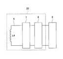
- FIG. 1Ais a diagram showing a configuration of a charging system including a power repeater using magnetic field resonance
- FIG. 1Bis a diagram showing an equivalent circuit of the charging system shown in FIG. 1A.
- the charging system 50 including the power repeater 100 of the first embodimentincludes a primary side coil 1, a primary side resonance coil 2, a secondary side resonance coil 3, a secondary side coil 4, and a matching A circuit 5, an AC power supply 6, a rectifier circuit 7, and a DC-DC converter 8 are included.
- a battery 9is connected to the charging system 50.
- the primary side coil 1, the primary side resonance coil 2, the matching circuit 5, and the AC power source 6are included in a power transmitter 10 that transmits power.
- the secondary side resonance coil 3is included in the power repeater 100.
- the power repeater 100is disposed between the power transmitter 10 and the power receiver 20, relays the power received from the power transmitter 10, and transmits the power to the power receiver 20.
- Secondary coil 4, rectifier circuit 7, and DC-DC converter 8are included in power receiver 20.
- a battery 9is connected to the power receiver 20.
- the primary side coil 1, the primary side resonance coil 2, the matching circuit 5, and the AC power source 6 included in the power transmitter 10will be described.
- the primary coil 1is a loop-shaped coil, and an AC power source 6 is connected between both ends via a matching circuit 5.
- the primary coil 1is disposed in close contact with the primary resonance coil 2 in a non-contact manner, and is electromagnetically coupled to the primary resonance coil 2.
- the primary coil 1is arranged so that its own central axis coincides with the central axis of the primary resonance coil 2. Matching the central axes improves the coupling strength between the primary side coil 1 and the primary side resonance coil 2 and suppresses leakage of magnetic flux, so that unnecessary electromagnetic fields are generated on the primary side coils 1 and 1. This is to suppress the generation around the secondary resonance coil 2.
- the primary coil 1can be represented as a coil having an inductance L1.
- the primary coil 1actually includes a resistance component and a capacitor component, but is omitted in FIG. 1B.
- the primary side coil 1generates a magnetic field by the AC power supplied from the AC power source 6 through the matching circuit 5, and transmits the power to the primary side resonance coil 2 by electromagnetic induction (mutual induction).
- the primary side resonance coil 2is disposed in close proximity to the primary side coil 1 and is electromagnetically coupled to the primary side coil 1.
- the primary side resonance coil 2has a predetermined resonance frequency and is designed to have a very high Q value.
- the resonance frequency of the primary side resonance coil 2is made equal to the resonance frequency of the secondary side resonance coil 3.
- both ends of the primary side resonance coil 2are opened from the viewpoint of easy viewing, but a capacitor for adjusting the resonance frequency is connected in series between both ends of the primary side resonance coil 2. There is also a case.
- the primary side resonance coil 2is arranged so that its center axis coincides with the center axis of the secondary side resonance coil 3 at a predetermined interval.
- the distance between the primary side resonance coil 2 and the secondary side resonance coil 3may be about several meters, for example. If the resonance Q of the primary side resonance coil 2 and the secondary side resonance coil 3 is sufficiently large, electric power can be transmitted by magnetic field resonance even if they are separated by several meters. The reason why the central axes are aligned is to cause good magnetic field resonance between the primary side resonance coil 2 and the secondary side resonance coil 3.
- the primary side resonance coil 2can be represented as a loop circuit having a coil having an inductance L2 and a capacitor having a capacitance C2.
- Capacitance C ⁇ b> 2is a capacitance of a capacitor connected for frequency adjustment between both ends of the primary side resonance coil 2.
- the primary side resonance coil 2actually includes a resistance component, but is omitted in FIG. 1B.
- the resonance frequency of the primary side resonance coil 2is set to be the same frequency as the frequency of the AC power output from the AC power source 6.
- the resonance frequency of the primary side resonance coil 2is determined by the inductance L2 and the capacitance C2 of the primary side resonance coil 2. For this reason, the inductance L2 and the capacitance C2 of the primary side resonance coil 2 are set so that the resonance frequency of the primary side resonance coil 2 is the same as the frequency of the AC power output from the AC power source 6. Yes.
- the primary side resonance coil 2may be open at both ends if the resonance frequency can be set only by the parasitic capacitance and the stray capacitance of the primary side resonance coil 2 can be fixed.
- the matching circuit 5is inserted for impedance matching between the primary coil 1 and the AC power source 6 and includes an inductor L and a capacitor C.
- the AC power source 6is a power source that outputs AC power having a frequency necessary for magnetic field resonance, and includes an amplifier that amplifies the output power.
- the AC power supply 6outputs high-frequency AC power of about several hundred kHz to several tens of MHz, for example.
- the power transmitter 10including the primary side coil 1, the primary side resonance coil 2, the matching circuit 5, and the AC power source 6 described above converts AC power supplied from the AC power source 6 to the primary side coil 1 by magnetic induction. Power is transmitted to the secondary resonance coil 2, and power is transmitted from the primary resonance coil 2 to the secondary resonance coil 3 of the power repeater 100 by magnetic field resonance.
- the secondary side resonance coil 3 included in the power repeater 100is separated from the primary side resonance coil 2 by a predetermined distance, and its own central axis is the central axis of the primary side resonance coil 2. Are arranged to match.
- both ends of the secondary side resonance coil 3are open from the viewpoint of easy viewing, but a capacitor for adjusting the resonance frequency is connected in series between both ends of the secondary side resonance coil 3. There is also.
- the secondary side resonance coil 3has the same resonance frequency as the primary side resonance coil 2 and is designed to have a very high Q value.
- the distance between the secondary resonance coil 3 and the primary resonance coil 2may be, for example, about several meters. Even if the resonance Q is sufficiently large, the secondary resonance coil 3 and the primary resonance coil 2 can transmit power by magnetic resonance even if they are separated by several meters.
- the secondary resonance coil 3is disposed in close contact with the secondary coil 4 in a non-contact manner, and is electromagnetically coupled to the secondary coil 4.
- the secondary resonance coil 3can be represented as having a coil with an inductance L3 and a capacitor with a capacitance C3.
- the capacitance C3is a capacitance of a capacitor connected for frequency adjustment between both ends of the secondary side resonance coil 3.
- the secondary resonance coil 3actually includes a resistance component, but is omitted in FIG. 1B.
- the resonance frequency of the secondary resonance coil 3is determined by the inductance L3 and the capacitance C3 of the secondary resonance coil 3. Therefore, the inductance L3 and the capacitance C3 of the secondary side resonance coil 3 are such that the resonance frequency of the secondary side resonance coil 3 is the resonance frequency of the primary side resonance coil 2 and the frequency of the AC power output from the AC power source 6. Is set to the same frequency.
- the secondary resonance coil 3may be open at both ends when the resonance frequency can be set only by the parasitic capacitance and the stray capacitance of the secondary resonance coil 3 can be fixed.
- the power repeater 100 including the secondary resonance coil 3relays the electric power transmitted from the primary resonance coil 2 of the power transmitter 10 by magnetic field resonance and transmits the power to the power receiver 20.
- the secondary side coil 4is a loop-like coil similar to the primary side coil 1, and is electromagnetically coupled to the secondary side resonance coil 3, and a rectifier circuit 7 is provided between both ends. It is connected.
- the secondary coil 4is arranged so that its own central axis coincides with the central axis of the secondary resonance coil 3.
- the secondary coil 4is disposed in close contact with the secondary resonance coil 3 in a non-contact manner, and is electromagnetically coupled to the secondary resonance coil 3.
- Matching the central axesimproves the coupling strength between the secondary side resonance coil 3 and the secondary side coil 4 and suppresses leakage of magnetic flux, so that unnecessary electromagnetic fields are generated by the secondary side resonance coils 3 and 2. This is to suppress the generation around the secondary coil 4.
- the secondary coil 4can be expressed as a coil having an inductance L4.
- the secondary coil 4actually includes a resistance component and a capacitor component, but is omitted in FIG. 1B.
- the secondary coil 4receives power from the secondary resonance coil 3 by electromagnetic induction (mutual induction) and supplies the power to the rectifier circuit 7.
- the rectifier circuit 7includes four diodes 7A to 7D and a capacitor 7E.
- the diodes 7A to 7Dare connected in a bridge shape, and perform full-wave rectification on the electric power input from the secondary coil 4 and output it.
- the capacitor 7Eis a smoothing capacitor connected to the output side of the bridge circuit including the diodes 7A to 7D.
- the capacitor 7Esmoothes the power that has been full-wave rectified by the bridge circuit including the diodes 7A to 7D and outputs it as DC power.
- the DC-DC converter 8is connected to the output side of the rectifier circuit 7 and converts the DC power voltage output from the rectifier circuit 7 into the rated voltage of the battery 9 and outputs it.
- the DC-DC converter 8steps down the output voltage of the rectifier circuit 7 to the rated voltage of the battery 9. Further, when the output voltage of the rectifier circuit 7 is lower than the rated voltage of the battery 9, the DC-DC converter 8 boosts the output voltage of the rectifier circuit 7 to the rated voltage of the battery 9.
- the power receiver 20including the secondary coil 4, the rectifier circuit 7, and the DC-DC converter 8 described above converts AC power transmitted from the secondary resonance coil 3 of the power repeater 100 by electromagnetic induction into DC power. Further, the voltage is converted to the rated voltage of the battery 9 and supplied to the battery 9.
- the battery 9may be a secondary battery that can be repeatedly charged.
- a lithium ion batterymay be used.
- the primary side coil 1, the primary side resonance coil 2, the secondary side resonance coil 3, and the secondary side coil 4are produced by winding a copper wire, for example.
- the material of the primary side coil 1, the primary side resonance coil 2, the secondary side resonance coil 3, and the secondary side coil 4may be a metal other than copper (for example, gold, aluminum, etc.).
- the material of the primary side coil 1, the primary side resonance coil 2, the secondary side resonance coil 3, and the secondary side coil 4may differ.
- the primary side coil 1 and the primary side resonance coil 2are the power transmission side
- the secondary side coil 3 and the secondary side resonance coil 4are the power reception side.
- the charging system 50is a magnetic field resonance system that transmits electric power from the power transmission side to the power reception side using magnetic field resonance generated between the primary side resonance coil 2 and the secondary side resonance coil 3. For this reason, the charging system 50 can transmit power over a longer distance than the electromagnetic induction method in which power is transmitted by electromagnetic induction from the power transmission side to the power reception side.
- FIG. 1illustrates the case where the central axis of the primary side resonance coil 2 and the central axis of the secondary side resonance coil 3 coincide with each other.
- the positions of the coil on the power transmission side and the coil on the power reception sideare described.
- the magnetic field resonance methodhas a merit that it has a higher degree of freedom than the electromagnetic induction method with respect to the distance or positional deviation between the resonance coils and is position-free.
- the charging system 50 based on the magnetic field resonance methodis expected to be used for non-contact charging in small electronic devices such as mobile phone terminals or smartphone terminals, home appliances, or electric vehicles.
- FIG. 2Ais a perspective view showing the power repeater 100 according to the first embodiment
- FIG. 2Bis a view showing a cross section taken along the line AA in FIG. 2A.
- the cross section taken along the line AAis a cross section passing through the central axis of the secondary resonance coil 3.
- the power repeater 100 of the first embodimentincludes a cover unit 101 and a secondary resonance coil 3.
- the cover portion 101is molded into the shape of a jacket of a smartphone terminal, and is produced by insert molding of a thermoplastic polycarbonate resin, for example.
- the secondary resonance coil 3is included in the cover part 101 when the cover part 101 is insert-molded with polycarbonate resin.
- the jacket-type cover unit 101is attached to the smartphone terminal by engaging with the housing of the smartphone terminal.
- the dimension of the cover part 101changes with models of a smart phone terminal, for example, length is about 120 mm, width is about 60 mm, and height is about 10 mm.
- the thickness of the polycarbonate resinvaries depending on the part. For example, the thickness is about 1 mm in the part where the secondary resonance coil 3 is not present, and is about 1.5 mm in the part where the secondary resonance coil 3 is present. .
- the jacketmainly protects the case from scratches or impacts by covering parts of the case other than the touch panel (mainly side and back) of the smartphone terminal, or various colors and characters.
- the external appearance of a smart phone terminalis decorated.
- the jacketmay be attached by engaging the housing of the smartphone terminal, or may be attached by an adhesive seal, an adhesive, or the like.
- the cover portion 101is preferably made of a nonmagnetic material and a nonconductive material. For this reason, in Embodiment 1, the cover part 101 is formed with polycarbonate resin. The reason why the cover portion 101 is formed of a non-magnetic material is to suppress disturbance or loss of magnetic flux and not to affect the resonance characteristics of the secondary resonance coil 3.
- the cover 101is formed of a non-conductive material because the power repeater 100 suppresses power loss due to generation of eddy current or the like when the power repeater 100 relays power between the power transmitter 10 and the power receiver 20. Because.
- the smart phone terminal to which the power repeater 100 of the first embodiment is attachedhas a secondary coil 4 (see FIGS. 1A and 1B) built in on the back side (surface opposite to the touch panel), and electromagnetic waves are transmitted from the power transmitter. Power can be received by induction, and the built-in battery can be charged while not connected to the power transmitter.
- the smart phone terminal to which the power repeater 100 of Embodiment 1 is attachedwill be described later with reference to FIGS. 4 and 5.
- the cover unit 101is mounted to protect the case of the smartphone terminal from scratches or impacts by covering the touch panel of the smartphone terminal and the surrounding area (mainly the side and the back).
- the cover part 101may be transparent, and various coloring or decoration may be performed.
- the secondary resonance coil 3is built in the cover unit 101.
- the secondary resonance coil 3is adjacent to the secondary coil 4 of the smartphone terminal on the back side of the smartphone terminal, and the secondary coil 4 and the central axis.
- Matching the central axesimproves the coupling strength between the secondary side resonance coil 3 and the secondary side coil 4 and suppresses leakage of magnetic flux, so that unnecessary electromagnetic fields are generated by the secondary side resonance coils 3 and 2. This is to suppress the generation around the secondary coil 4.
- the power repeater 100may be produced, for example, by molding a polycarbonate resin so as to enclose the secondary resonance coil 3 in a state where the secondary resonance coil 3 is aligned.
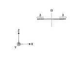
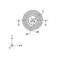
- FIG. 3Ais a plan view showing the secondary resonance coil 3 of the power repeater 100 according to the first embodiment
- FIG. 3Bis a view showing a cross section taken along line BB in FIG. 3A.
- the cross section taken along the line BBis a cross section passing through the central axis of the secondary resonance coil 3. Note that an XYZ coordinate system is defined as shown in FIGS. 3A and 3B.
- the secondary resonance coil 3is a spiral planar coil having four turns, and the end portions 3A and 3B are connected to a capacitor (not shown). The resonance frequency of the secondary resonance coil 3 is adjusted by connecting both ends to a capacitor (not shown).
- An equivalent circuit diagram of the secondary resonance coil 3is as shown in FIG. 1B.
- a capacitor having a capacitance C3 illustrated in FIG. 1Bis a capacitance of a capacitor connected between the end portions 3A and 3B.
- the resonance frequencycan be set only by the parasitic capacitance of the secondary side resonance coil 3, it is not necessary to connect a capacitor for adjusting the resonance frequency between the end portions 3A and 3B. In this case, the end portions 3A and 3B are opened.
- FIGS. 4A to 4Da smartphone terminal equipped with the power repeater 100 of the first embodiment will be described with reference to FIGS. 4A to 4D, FIGS. 5A, and 5B.
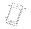
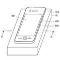
- FIG. 4Ais a perspective view showing the front side of the smartphone terminal 500 to which the power repeater 100 of the first embodiment is attached
- FIG. 4Bis a perspective view showing the back side of the smartphone terminal 500
- FIG. 4Cis a diagram showing a cross-section taken along the line CC of FIG. 4B
- FIG. 4Dis a circuit diagram showing main components included in the smartphone terminal 500.
- the cross section taken along the line CCis a cross section passing through the central axis of the secondary coil 4.
- the smart phone terminal 500 to which the power repeater 100 of the first embodiment is attachedincludes a touch panel 501 (see FIG. 4A) disposed on the front side and a secondary coil 4 (FIG. 4B, incorporated on the back side). 4C).
- the smart phone terminal 500includes the power receiver 20 and the battery 9 as shown in FIG. 4D.
- the power receiver 20includes the secondary coil 4.
- the smartphone terminal 500further includes a CPU (Central Processing Unit) that performs calls, communication, and various arithmetic processing, a memory, and the like, but the description thereof is omitted here.
- a CPUCentral Processing Unit
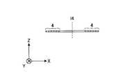
- FIG. 5Ais a plan view showing the secondary coil 4 included in the smartphone terminal 500
- FIG. 5Bis a view showing a cross section taken along the line DD in FIG. 5A.
- the DD cross-sectionis a cross section passing through the central axis 14 of the secondary coil 4. Note that an XYZ coordinate system is defined as shown in FIGS. 5A and 5B.
- the secondary coil 4is a spiral planar coil having 6 turns, and the end portions 4A and 4B are connected to the rectifier circuit 7 (see FIGS. 1A and 1B).
- An equivalent circuit diagram of the secondary coil 4is as shown in FIG. 1B.
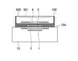
- FIG. 6Ais a perspective view showing a front side of the smart phone terminal 500 on which the power repeater 100 of the first embodiment is mounted
- FIG. 6Bis a rear view of the smart phone terminal 500 on which the power repeater 100 of the first embodiment is mounted.
- FIG. 6Cis a diagram showing a cross-section taken along the line EE of FIG. 6B.
- the cross section taken along the line EEis a cross section passing through the central axis l3 of the secondary resonance coil 3 and the central axis l4 of the secondary coil 4.
- the secondary resonance coil 3 built in the power repeater 100is built into the back side of the smartphone terminal 500. It is arranged close to the secondary coil 4. In this state, as shown in FIG. 6C, the center axis l3 of the secondary side resonance coil 3 and the center axis l4 of the secondary side coil 4 coincide.
- the secondary coil 4 of the smartphone terminal 500is electromagnetically coupled to the secondary resonance coil 3 of the power repeater 100.
- the smartphone terminal 500can receive power through magnetic resonance via the power repeater 100 and charge the battery 9. become.
- FIG. 7Ais a perspective view showing power transmitter 10 used for charging smartphone terminal device 500 equipped with power repeater 100 according to Embodiment 1
- FIG. 7Bis a diagram showing a cross section taken along line FF in FIG. 7A.
- the cross section taken along the line FFis a cross section passing through the central axis 11 of the primary coil 1 and the central axis 12 of the primary resonance coil 2.
- FIG. 7Cis a plan view showing the primary side coil 1 and the primary side resonance coil 2 included in the power transmitter 10, and FIG. 7D is a view showing a cross section taken along line GG in FIG. 7C. Note that an XYZ coordinate system is defined as shown in FIGS. 7C and 7D.
- the power transmitter 10includes a primary side coil 1 and a primary side resonance coil 2.
- the upper surface 10A of the power transmitter 10is a surface over which an electronic device is held when charging an electronic device such as a smart phone terminal or a mobile phone terminal incorporating a magnetic field resonance type power receiving device.
- FIGS. 7A and 7Bdo not show the matching circuit 5 and the AC power supply 6 of the power transmitter 10, but the primary coil 1 of the power transmitter 10 shown in FIGS. 7A and 7B has the same structure as that shown in FIGS. 1A and 1B. As shown, an AC power supply 6 is connected via a matching circuit 5.
- the primary coil 1is a loop-shaped planar coil having one turn, and an AC power source 6 is connected to the ends 1A and 1B via a matching circuit 5.
- the primary resonance coil 2is a spiral planar coil having four turns, and the end portions 2A and 2B are connected to a capacitor (not shown).
- the resonance frequency of the primary side resonance coil 2is adjusted by connecting both ends to a capacitor (not shown).
- An equivalent circuit diagram of the primary side resonance coil 2is as shown in FIG. 1B.
- the capacitor having the capacitance C2 shown in FIG. 1Bis a combined capacitance of the parasitic capacitance of the primary side resonance coil 2 and the capacitance of the capacitor connected between the end portions 2A and 2B.
- the resonance frequencycan be set only by the parasitic capacitance of the primary side resonance coil 2
- the end portions 2A and 2Bmay be connected to make the primary side resonance coil 2 a loop-shaped coil.
- the ends 2A and 2Bmay be opened.
- the primary side resonance coil 2is disposed closer to the upper surface 10 ⁇ / b> A than the primary side coil 1.
- the primary coil 1is disposed in the vicinity of the primary resonance coil 2.
- the central axis l1 of the primary coil 1 and the central axis l2 of the primary resonance coil 2coincide.
- the primary side coil 1is electromagnetically coupled to the primary side resonance coil 2.
- AC power output from the AC power source 6is transmitted to the primary side resonance coil 2 of the power transmitter 10 from the primary side coil 1 by electromagnetic induction.
- FIG. 8A and FIG. 8Ba method of charging the smartphone terminal device 500 equipped with the power repeater 100 of the first embodiment will be described.
- FIG. 8Ais a perspective view illustrating a state in which the smartphone terminal 500 on which the power repeater 100 according to Embodiment 1 is mounted is held over the power transmitter 10, and FIG. 8B illustrates a cross-section taken along the line HH in FIG. 8A.
- FIG. The HH arrow cross sectionis a cross section passing through the central axis of the primary side coil 1, the primary side resonance coil 2, the secondary side resonance coil 3, and the secondary side coil 4.
- the primary resonance coil 2 of the power transmitter 10 and the power repeater 100 2Magnetic field resonance occurs between the secondary side resonance coil 3 and the secondary side resonance coil 3.
- the AC power output from the AC power supply 6 (see FIGS. 1A and 1B) of the power transmitter 10is transmitted from the primary coil 1 to the primary resonance coil 2 by electromagnetic induction, and the primary resonance coil. 2 is transmitted to the secondary resonance coil 3 of the power repeater 100 by magnetic field resonance.
- the power transmitted to the secondary resonance coil 3 of the power repeater 100is transmitted to the secondary coil 4 of the smartphone terminal 500 by electromagnetic induction.
- the smartphone terminal 500 with the power repeater 100is placed close to the power transmitter 10 so that the central axes of the primary side resonance coil 2 and the secondary side resonance coil 3 are substantially coincident. Indicates the state. However, since the power repeater 100 and the smartphone terminal 500 receive power from the power transmitter 10 by magnetic field resonance, the power transmitter 10, the power repeater 100, and the smartphone terminal 500 are, for example, about several meters apart. Can also transmit power. Further, even when the central axes of the primary side resonance coil 2 and the secondary side resonance coil 3 do not coincide with each other, power can be transmitted efficiently.
- the smart phone terminal 500can receive power and charge the battery 9.
- Power transmission by magnetic resonanceis more resistant to displacement between the power transmission side and the power reception side than power transmission by electromagnetic induction, and power transmission is possible even if the power transmission side and the power reception side are not close to each other and are some distance apart. There is a merit of position-free.
- the power repeater 100 of the first embodimentis attached to the smartphone terminal 500 in the transition period as described above, even if the smartphone terminal 500 is compatible with the electromagnetic induction type power transmission method, the magnetic field resonance is performed.
- the powercan be transmitted by using this, and convenience is improved.
- the power repeater 100 of the first embodimentis a jacket type, it is very easy to attach to the smartphone terminal 500.
- the power repeater 100 including the secondary resonance coil 3can be easily retrofitted to the smartphone terminal 500 including the electromagnetic induction type power receiver 20, and the smartphone terminal 500 can be attached to the magnetic field resonance type receiver. It can be easily converted into a device having an electric appliance.
- the power repeater 100since the power repeater 100 includes the secondary resonance coil 3 realized by a planar coil, the increase in thickness can be minimized as compared with a jacket not including the secondary resonance coil 3. it can. For this reason, there is almost no influence on the external appearance of the smart phone terminal 500, and the user who uses the smart phone terminal 500 hardly feels uncomfortable.
- the power repeater 100 of the first embodimentis suitable for users who want to convert the smartphone terminal 500 including the electromagnetic induction type power receiver 20 to a magnetic resonance type. Is a very useful product.
- the power repeater 100is highly reliable because it does not make a wired electrical connection with the smartphone terminal 500.
- the power transmitter 10is of the magnetic field resonance type.
- the user of the smartphone terminal device 500 with the power repeater 100 attachedcan receive the primary side resonance coil.
- the battery 9 of the smartphone terminal 500may be charged with an electromagnetic induction type power transmitter that does not include 2.
- the jacket-type power repeater 100is removed from the smartphone terminal 500, the power received from the electromagnetic induction-type power transmitter is received by the power receiver 20 of the smartphone terminal 500, so that the battery 9 can be charged. Since the power repeater 100 according to the first embodiment is a jacket type, it is very easy to attach and detach, and when the power transmitter is an electromagnetic induction type, the smartphone terminal 500 is removed by removing the power repeater 100. The battery 9 can be charged.
- the smartphone terminal 500 including the electromagnetic induction type power receiver 20is made compatible with the magnetic field resonance type and the electromagnetic induction type power receiver. be able to.
- the cover 101 (see FIGS. 2A and 2B) of the power repeater 100is the jacket of the smartphone terminal 500.
- the cover 101 of the power repeater 100is limited to the jacket. It is not something.
- the cover unit 101only needs to be attached so that the position of the secondary resonance coil 3 is aligned with the secondary coil 4 of an electronic device that charges a rechargeable battery with power received by electromagnetic induction.
- an electronic deviceinclude a mobile phone terminal, a PC (Personal Computer), a digital camera, a digital video camera, or a portable game machine in addition to the smartphone terminal 500.
- the secondary resonance coil 3is a spiral planar coil and has four turns. However, if the shape of the secondary side resonance coil 3 can receive power from the primary side resonance coil 2 by magnetic field resonance and electromagnetically couple with the secondary side coil 4 and can transmit power by electromagnetic induction, It is not limited to a spiral planar coil. Similarly, the number of turns of the secondary resonance coil 3 is not limited to four.
- the shape of the secondary resonance coil 3may be, for example, a rectangle in a plan view, or may be formed so as to spiral in a rectangular shape. Further, the number of turns of the secondary side resonance coil 3 may be optimized in relation to the primary side resonance coil 2 and the secondary side coil 4, and may be any number of turns.
- the power repeater 100is mounted on the smartphone terminal 500 which is an example of the electronic apparatus.
- the power repeater 100may be mounted on the upper surface 10 ⁇ / b> A of the power transmitter 10.
- the cover 101 of the power repeater 100may be a simple sheet type instead of a jacket type.
- the polycarbonate resinis insert-molded so that the secondary resonance coil 3 is incorporated in the cover 101 of the power repeater 100.
- the power repeater 100is limited to such a configuration. Is not to be done.
- the secondary side resonance coil 3may be affixed to the cover part 101 using a sheet-like sealing member, for example.
- the power repeater 100may be manufactured by printing the secondary resonance coil 3 on the surface of the cover part 101 after the cover part 101 is formed by injection molding.
- the secondary resonance coil 3may be formed on either the surface of the cover portion 101 that contacts the smartphone terminal 500 or the surface that does not contact, for example, a protective sheet or the like. You may protect it. Further, a thin substrate or the like may be bonded instead of the protective sheet.
- a magnetic material powder or the likemay be mixed into the polycarbonate resin, or a magnetic material sheet is included. Insert molding may be performed as described above.
- the cover portion 101is made of polycarbonate resin.
- the cover portion 101is not limited to polycarbonate resin, and may be a nonmagnetic material and a nonconductive material.
- a resin other than polycarbonate resinmay be used.
- an acrylic resinmay be used.
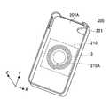
- FIG. 9Ais a perspective view showing the power repeater 200 of the second embodiment
- FIG. 9Bis a cross-sectional view of the state in which the power repeater 200 is attached to the smartphone terminal 500.
- the cross section shown in FIG. 9Bis a cross section passing through the central axis of the primary side coil 1, the primary side resonance coil 2, the secondary side resonance coil 3, and the secondary side coil 4.
- 9Ais parallel to the short direction of the power repeater 200
- the Y axisis parallel to the longitudinal direction
- the Z axisextends in the thickness direction.
- the power repeater 200 according to the second embodimentincludes a jacket-type cover 201 for the smartphone terminal 500, similarly to the cover 101 of the power repeater 100 according to the first embodiment.
- the power relay of the first embodimentis that a magnetic sheet 210 disposed in a region overlapping the secondary resonance coil 3 in a plan view is built in the cover unit 201. Different from the vessel 100.
- the magnetic sheet 210is a sheet-like member formed of a magnetic material, and is an example of a magnetic body portion that can be formed of a magnetic material having a relatively high magnetic permeability. Further, the magnetic sheet 210 needs to be formed of a non-conductive material in order to prevent loss due to generation of eddy current or the like. For this reason, the magnetic sheet 210 can be made of, for example, a ferrite-based or manganese-based material.
- the power repeater 200is a jacket type for the smartphone terminal 500, it is preferable that the power repeater 200 be as thin as possible. For this reason, the magnetic sheet 210 is preferably as thin as possible.
- the magnetic sheet 210is disposed to reduce the coupling strength between the secondary resonance coil 3 and the secondary coil 4 without increasing the thickness of the jacket-type power repeater 200. For this reason, it is preferable that the magnetic permeability is high.
- the magnetic permeabilitysince the magnetic permeability has frequency characteristics, it may be set according to the frequency of the AC power transmitted between the secondary side resonance coil 3 and the secondary side coil 4.
- the magnetic sheet 210is a sheet-like member formed of a ferrite-based material, and exhibits a magnetic permeability 200 at a frequency of 2 MHz.
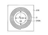
- the magnetic sheet 210is a rectangular sheet-like member in plan view, and has a circular opening 210A at the center.
- the opening 210Ais formed, for example, by opening a punch hole with a punching device.
- the center of the opening 210 ⁇ / b> Acoincides with the central axis of the secondary resonance coil 3. However, the center of the opening 210 ⁇ / b> A does not necessarily have to coincide with the central axis of the secondary resonance coil 3.
- the cross section shown in FIG. 9Bis when the power repeater 200 is mounted on the smartphone terminal 500 and the central axis of the secondary resonance coil 3 is cut in the short direction (X-axis direction) of the cover unit 201. Represents an arrow cross section.
- the magnetic sheet 210is disposed closer to the surface 201 ⁇ / b> A (see FIG. 9A) attached to the smartphone terminal 500 than the secondary resonance coil 3. This is for optimizing the power transmission efficiency between the secondary side resonance coil 3 and the primary side resonance coil 2 of the power transmitter 10.
- the power repeater 200inserts the cover portion 201 with a polycarbonate resin so as to enclose the secondary resonance coil 3 and the magnetic sheet 210 with the magnetic sheet 210 superimposed on the secondary resonance coil 3, for example. What is necessary is just to produce by shaping
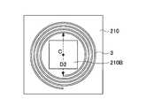
- 10A and 10Bare plan views showing the magnetic sheet 210 and the secondary resonance coil 3 included in the power repeater 200 of the second embodiment.
- the magnetic sheet 210is a rectangular sheet-like member that is larger than the secondary resonance coil 3 in plan view.
- the opening 210Ais aligned so that the center C coincides with the central axis of the secondary resonance coil 3, and the diameter D1 of the opening 210A is the innermost loop of the secondary resonance coil 3. It is set smaller than the inner diameter D2.
- a rectangular opening 210Bmay be formed in the magnetic sheet 210 as shown in FIG. 10B.
- the reason why the magnetic sheet 210 is disposed closer to the surface 201A (see FIG. 9A) attached to the smartphone terminal 500 than the secondary resonance coil 3is as follows.
- the coupling strength with the primary side coil 1is increased so that the power reception efficiency by electromagnetic induction is optimal. Further, the shape, size, number of turns and the like of the secondary coil 4 are optimized.
- the secondary side coil 4is designed so that the coupling strength with the primary side coil 1 is increased, when the power repeater 200 incorporating the secondary side resonance coil 3 is attached to the smartphone terminal 500, 2
- the coupling strength between the secondary resonance coil 3 and the secondary coil 4may be excessive.
- the secondary side coil 4causes 2 to be transmitted.
- the power extracted from the secondary resonance coil 3is relatively large, and the power transmission efficiency due to the magnetic field resonance is lowered.
- the coupling strength between the secondary side resonance coil 3 and the secondary side coil 4is lowered. You can do it.
- a magnetic sheet 210may be provided.
- the magnetic sheet 210is disposed closer to the surface 201A (see FIG. 9A) attached to the smartphone terminal 500 than the secondary resonance coil 3 of the power repeater 200. .
- the secondary resonance coil 3 and the secondary sideare used by using the magnetic sheet 210.
- the coupling strength of the side coil 4it is possible to improve the power transmission efficiency by magnetic field resonance.
- FIG. 11is a cross-sectional view illustrating a state in which power is transmitted from the power transmitter 10 to the smartphone terminal 500.
- FIG. 11in addition to the state in which the power repeater 200 of the second embodiment is mounted on the smartphone terminal 500, the state in which the power repeater 100 of the first embodiment is mounted on the smartphone terminal 500 for comparison. The state which used the smart phone terminal 500 alone (without mounting
- the power transmission efficiencyis a percentage of the AC power output from the secondary coil 4 with respect to the AC power input to the primary coil 1.
- the primary side coil 1, the primary side resonance coil 2, the secondary side resonance coil 3, and the secondary side coil 4are all made by winding a copper wire. And having the number of turns was performed by electromagnetic field simulation.
- the wire diameter of the primary coil 1was 0.5 mm, the outer diameter was 20 mm, and the number of turns was 1.
- the primary resonance coil 2has a wire diameter of 0.5 mm, an outer diameter of 30 mm, and a winding number of 4.
- the wire diameter of the secondary resonance coil 3was 0.5 mm, the outer diameter was 30 mm, and the number of turns was 4.
- the wire diameter of the secondary coil 4was 0.5 mm, the outer diameter was 30 mm, and the number of turns was 15.
- the outer diameter of the primary side coil 1is the outer diameter of a copper wire wound in a loop shape.
- the primary side resonance coil 2, the secondary side resonance coil 3, and the secondary side coil 4are planar coils wound in a spiral shape, the outer diameter is a copper wire wound in a spiral shape. It is the maximum outer diameter.
- the magnetic sheet 210 of the power repeater 200is 40 mm in length and width in plan view, 0.2 mm in thickness, 200 in permeability, and the opening 210A is a circular opening having a diameter of 22 mm. The condition was set.
- the frequency of the AC power input to the primary coil 1was set to 2 MHz, and conditions were set so that a load resistor having a resistance value of 10 ⁇ was connected to the secondary coil 4.
- the power transmission efficiency when the smartphone terminal 500 was directly held over the power transmitter 10 without mounting the power repeater 100 or 200was 63.6%.
- the secondary coil 4 of the smartphone terminal 500receives power from the primary resonance coil 2 (or both the primary coil 1 and the primary resonance coil 2) by electromagnetic induction. ing.
- the smartphone terminal 500 including the secondary coil 4 optimized for the electromagnetic induction type power transmission methodis directly held over the magnetic field resonance type power transmitter 10. This is probably because the coupling strength between the secondary side coil 4 (or both the primary side coil 1 and the primary side resonance coil 2) and the secondary side coil 4 was low.
- the power transmitter 10adopting the magnetic field resonance type power transmission method
- the smartphone terminal 500 that employs an electromagnetic induction type power transmission methodis directly held over. In such a case, the time required for charging the battery 9 of the smartphone terminal 500 becomes longer, or about 40% of the power output from the power transmitter 10 is lost without being transmitted to the smartphone terminal 500. Therefore, it is inefficient.
- the power transmission efficiency when the smartphone terminal 500 on which the power repeater 100 of the first embodiment is mounted is held over the power transmitter 10is 77.7%, compared with the case illustrated in FIG. 11A.
- the power transmission efficiencyhas been greatly improved.
- the power repeater 100is a jacket type and can be easily attached to the smartphone terminal 500, the electromagnetic induction type power transmission method has been popularized first, and the magnetic field resonance type power transmission method has started to be popularized later. In this case, it is very effective.
- the power transmission efficiency when the smartphone terminal 500 equipped with the power repeater 200 according to the second embodiment is held over the power transmitter 10is 88.7%, compared with the case illustrated in FIG. 11B.
- the power transmission efficiencywas further improved.
- the power transmission efficiencyis improved in the case shown in FIG. 11C because the coupling strength between the secondary side resonance coil 3 and the secondary side coil 4 is lowered by the magnetic sheet 210 of the power repeater 200, and the power transmitter 10. It is considered that the energy transmitted from the primary side resonance coil 2 to the secondary side resonance coil 3 of the power repeater 200 was efficiently transmitted to the secondary side coil 4.
- the power repeater 200 including the magnetic sheet 210is attached to the smartphone terminal 500 including the secondary coil 4 optimized for electromagnetic induction, the magnetic field resonance type power transmitter 10 to the smartphone terminal. Power can be efficiently transmitted to the machine 500.
- the power repeater 200 of Embodiment 2is a very useful product in the transition period when a power transmission system shifts as mentioned above.
- FIG. 12is a diagram showing the characteristics of the power transmission efficiency with respect to the diameter of the opening 210A of the magnetic sheet 210 of the power repeater 200.
- the diameter D1 (see FIG. 10A) of the opening 210Awas swung by 2 mm between 18 mm and 30 mm, and simulation was performed for seven types of diameters D1.
- the magnetic sheet 210is positioned between the secondary resonance coil 3 and the secondary coil 4, and the center of the opening 210 ⁇ / b> A is the center axis of the secondary resonance coil 3 and the center of the secondary coil 4. Coincides with the axis. For this reason, it is considered that when the diameter of the opening 210A is changed, the coupling strength between the secondary resonance coil 3 and the secondary coil 4 is changed.
- the current flowing through the primary side resonance coil 2is a1
- the current through the secondary side resonance coil 3is a2
- the angular frequency of the AC power transmitted from the primary side resonance coil 2 to the secondary side resonance coil 3is ⁇ is a coupling rate between the primary side resonance coil 2 and the secondary side resonance coil 3.
- the coupling rate ⁇is a coefficient (dimensionalless coefficient) proportional to the coupling coefficient between the primary side resonance coil 2 and the secondary side coil 4.
- the loss rate of the current lost due to the resistance or the like in the primary side resonance coil 2is ⁇ 2
- the loss rate of the current lost due to the resistance or the like in the secondary side resonance coil 3is changed from ⁇ 2 to the secondary side resonance coil 3
- the transmission rate of the current transmitted to the coil 4is ⁇ w.
- the loss rates ⁇ 1 and ⁇ 2are dimensionless coefficients proportional to the reciprocal of the Q value of the primary side resonance coil 2 and the secondary side resonance coil 3, respectively, and the power transmission rate ⁇ w is also a dimensionless coefficient.
- the time change (da2 / dt) of the current a2 flowing through the secondary resonance coil 3can be expressed by the equation (1).
- irepresents an imaginary unit.
- the third term ( ⁇ w ⁇ a2) on the right siderepresents the current transmitted from the secondary side resonance coil 3 to the secondary side coil 4, and the secondary side coil 4 to the secondary side coil 4. Represents that power is transmitted to
- electric power proportional to the power transmission rate ⁇ wis transmitted from the secondary side resonance coil 3 to the secondary side coil 4, and increasing the power transmission rate ⁇ w means that the secondary side resonance coil 3 and the secondary side coil 4 are increased.
- reducing the power transmission rate ⁇ wcan be interpreted to mean reducing the coupling strength between the secondary resonance coil 3 and the secondary coil 4.
- the AC power input to the primary coil 1is Pt
- the power received by the secondary coil 4is Pw
- the power transmission efficiency ⁇ wis defined by equation (2).
- the loss rates ⁇ 1 and ⁇ 2are proportional to the reciprocals of the Q value (Q1) of the primary side resonance coil 2 and the Q value (Q2) of the secondary side resonance coil 3, respectively. This is equivalent to the product of the coupling rate ⁇ and (Q1 ⁇ Q2) 1/2 .
- the loss rate ⁇ 2is a current loss rate in the secondary resonance coil 3, and is a fixed value determined by the Q value (Q2) of the secondary resonance coil 3. Therefore, the equation (2) for obtaining the power transmission efficiency ⁇ w can be considered as a quadratic equation in which the square term of the variable ⁇ w is included in the denominator.
- Equation (2)has a maximum value when the transmission rate ⁇ w takes a certain value.
- FIG. 13is a diagram showing the characteristics of the power transmission efficiency ⁇ w with respect to the value of ( ⁇ 2 / ⁇ w) included in the equation (2) with the value of fo set to 1, 10, 100.
- FIG. 13shows the characteristics as a semi-logarithmic graph with logarithmic display of ( ⁇ 2 / ⁇ w) on the horizontal axis.
- the loss rate ⁇ 2is a value that is proportional to the reciprocal of the Q value (Q2) of the secondary resonance coil 3, and is normally regarded as a fixed value. Therefore, the value of ( ⁇ 2 / ⁇ w) is changed. Is realized by changing the value of the power transmission rate ⁇ w.
- the power transmission rate ⁇ wis a coefficient representing the ratio of the current transmitted from the secondary resonance coil 3 to the secondary coil 4 as described above. Increasing the power transmission rate ⁇ w corresponds to increasing the coupling strength between the secondary side resonance coil 3 and the secondary side coil 4, and decreasing the power transmission rate ⁇ w corresponds to the secondary side resonance coil 3 and the secondary side coil. This corresponds to a decrease in the bond strength of 4.
- the coupling strength between the secondary resonance coil 3 and the secondary coil 4increases as the diameter D1 of the opening 210A of the magnetic sheet 210 increases, and the coupling strength decreases as the diameter D1 decreases. This is because as the diameter D1 of the opening 210A is larger, the interlinkage magnetic flux between the secondary side resonance coil 3 and the secondary side coil 4 is increased, and the electromagnetic field coupling becomes stronger.
- increasing the value of ( ⁇ 2 / ⁇ w)corresponds to decreasing the value of the power transmission rate ⁇ w included in the denominator. That is, this corresponds to reducing the coupling strength between the secondary side resonance coil 3 and the secondary side coil 4 by reducing the diameter D1 of the opening 210A.
- decreasing the value of ( ⁇ 2 / ⁇ w) in FIG. 13corresponds to increasing the value of the transmission rate ⁇ w included in the denominator. That is, this corresponds to increasing the coupling strength between the secondary resonance coil 3 and the secondary coil 4 by increasing the diameter D1 of the opening 210A.
- the diameter D1 of the opening 210A of the magnetic sheet 210decreases as the horizontal axis moves to the right, and the diameter D1 of the opening 210A of the magnetic sheet 210 increases as the horizontal axis moves to the left. To do.
- the power transmission efficiency ⁇ wcan be optimized by adjusting the diameter D1 of the opening 210A of the magnetic sheet 210. Further, it was found that the diameter D1 of the opening 210A has an optimum value that gives the maximum value of the power transmission efficiency ⁇ w.
- the coupling strength between the secondary side resonance coil 3 and the secondary side coil 4is too high, and therefore, between the primary side resonance coil 2 and the secondary side resonance coil 3. It is considered that the magnetic field resonance is not sufficiently generated.
- the magnetic sheet 210is disposed between the secondary side resonance coil 3 and the secondary side coil 4 as described above. In addition, it is conceivable to increase the distance between the secondary resonance coil 3 and the secondary coil 4.
- the power repeater 200 of the second embodimentis a jacket type for the smartphone terminal 500, the gap between the secondary resonance coil 3 and the secondary coil 4 is widened and the jacket becomes thick. It is not a realistic solution from the point of view of commercialization.
- the magnetic sheet 210is built in the power repeater 200 and the power transmission efficiency is optimized by optimizing the diameter D1 of the opening 210A of the magnetic sheet 210. Since the increase in thickness is only the thickness of the magnetic sheet 210, it can be said that it is preferable from the viewpoint of commercialization.
- the power repeater 200includes the magnetic sheet 210 disposed between the secondary side resonance coil 3 and the secondary side coil 4, the secondary side coil optimized for electromagnetic induction is used. 4, power can be efficiently transmitted from the power transmitter 10 to the smartphone terminal 500 by magnetic field resonance.
- the power repeater 200 of Embodiment 2is attached to the smartphone terminal 500, power is transmitted to the smartphone terminal 500 having the electromagnetic induction power receiving unit 20 by magnetic field resonance, and the battery 9 of the smartphone terminal 500 is transmitted. Can be charged.
- the user of the smartphone terminal 500goes to a place where there is only a magnetic resonance type power transmitter in a transitional state where the power transmission format shifts from the electromagnetic induction type to the magnetic field resonance type.
- the powercan be received by the smartphone terminal 500 by magnetic field resonance via the power repeater 200 and the battery 9 can be charged.
- a mode in which one circular opening 210A or one rectangular opening 210B is formed in the center of the magnetic sheet 210has been described, but a plurality of openings may be formed.
- the openingscan be arranged in various patterns. For example, a plurality of openings may be arranged like a polka dot pattern.
- the magnetic sheet 210is disposed closer to the surface 201A (see FIG. 9A) attached to the smartphone terminal 500 than the secondary resonance coil 3
- the magnetic layermay be formed on the side closer to the surface 201A than the secondary resonance coil 3 by mixing particles of a magnetic material into the polycarbonate resin.
- the cover portionmay be manufactured by forming a magnetic layer instead of the magnetic sheet 210 and laminating it with a layer formed of a polycarbonate resin that does not contain particles of the magnetic material.
- the opening 210Ais formed in the magnetic sheet 210.
- the coupling strength between the secondary resonance coil 3 and the secondary coil 4can be optimized without forming the opening 210A. If so, the opening 210A may not be formed.
- the magnetic sheet 210may be attached to the surface of the cover unit 201.
- the magnetic sheet 210is disposed not on the inside of the cover part 201 but on the outside.
- the secondary resonance coil 3is manufactured by winding a copper wire.
- the secondary resonance coil 3can be formed by printing, the surface of the magnetic sheet 210 is printed. May be.
- the secondary resonance coil 3may be formed by patterning a copper foil formed on the surface of the magnetic sheet 210.
Landscapes
- Engineering & Computer Science (AREA)
- Power Engineering (AREA)
- Computer Networks & Wireless Communication (AREA)
- Physics & Mathematics (AREA)
- Electromagnetism (AREA)
- Signal Processing (AREA)
- Charge And Discharge Circuits For Batteries Or The Like (AREA)
- Near-Field Transmission Systems (AREA)
Abstract
Description
Translated fromJapanese本発明は、電力中継器に関する。The present invention relates to a power repeater.
従来より、非接触給電において、電磁誘導コイルが自己共振コイルよりも対向するコイルユニットに近い側に設置されたコイルユニットを、送電装置および/または受電装置に有し、対向するコイルユニットのタイプに応じて、給電手法を切替える非接触電力伝送装置があった。この非接触電力伝送装置は、磁界共鳴による給電および電磁誘導による給電のいずれの給電手法によっても給電可能としていた。Conventionally, in non-contact power feeding, the power transmission device and / or the power receiving device has a coil unit installed on the side closer to the coil unit where the electromagnetic induction coil is opposed to the self-resonant coil. Accordingly, there has been a non-contact power transmission device that switches a power feeding method. This non-contact power transmission device can supply power by any one of power feeding methods using magnetic field resonance and electromagnetic induction.
また、無線により電力を受信できるように、携帯型電子デバイスに後から取り付けられる無線電力受信装置があった。この無線電力受信装置は、例えば接着材によって携帯型電子デバイスに取り付けられ、電力送信機と互いに近接する場合に電磁誘導により送信機から電力を受信する電力受信素子を備える。一又は複数の電力コネクタは、電力受信素子に電気的に接続され、無線電力受信装置が使用される場合に電力受信素子と電気的に結合され、電力受信素子により受信された電力を携帯型電子デバイスに供給するために携帯型電子デバイスの一又は複数の対応する電源コネクタに接続される。Also, there was a wireless power receiving device that is attached later to the portable electronic device so that it can receive power wirelessly. The wireless power receiving apparatus includes a power receiving element that is attached to a portable electronic device by an adhesive, for example, and receives power from the transmitter by electromagnetic induction when close to the power transmitter. The one or more power connectors are electrically connected to the power receiving element and are electrically coupled to the power receiving element when the wireless power receiving device is used, and the power received by the power receiving element is transferred to the portable electronic device. Connected to one or more corresponding power connectors of the portable electronic device for supply to the device.
従来の非接触電力伝送装置は、受電側が磁界共鳴型又は電磁誘導型のいずれの給電方式であるかにより、送電側のコイルを電磁誘導コイル又は自己共振コイルに切り替えていた。このため、コイルを切り替えるための装置が必要であり、簡易な構成で受電側に電力を供給することができなかった。In the conventional non-contact power transmission device, the coil on the power transmission side is switched to the electromagnetic induction coil or the self-resonance coil depending on whether the power receiving side is a magnetic resonance type or an electromagnetic induction type power feeding method. For this reason, the apparatus for switching a coil is required, and electric power could not be supplied to the power receiving side with a simple configuration.
また、従来の無線電力受信装置は、電力を携帯型電子デバイスに供給するには携帯型電子デバイスの電源コネクタに接続する必要があった。このため、無線電力受信装置と携帯型電子デバイスとの間は、無線による電力供給ではなく、有線による電力供給であり、簡易な構成で携帯型電子デバイスに電力を供給することはできなかった。また、電力の供給方式が電磁誘導型であるため、送電側の電力送信機と受電側の無線電力受信装置の位置ずれに弱く、電力送信機と無線電力受信装置を近接させなければ電力の供給を行うことができなかった。In addition, the conventional wireless power receiving apparatus needs to be connected to the power connector of the portable electronic device in order to supply power to the portable electronic device. For this reason, between the wireless power receiving apparatus and the portable electronic device is not wireless power supply but wired power supply, and power cannot be supplied to the portable electronic device with a simple configuration. In addition, since the power supply method is an electromagnetic induction type, it is vulnerable to misalignment between the power transmitter on the power transmission side and the wireless power receiver on the power receiver side, and power is supplied unless the power transmitter and the wireless power receiver are close to each other. Could not do.
以上のように、無線による電力の伝送方式には電磁誘導型と磁界共鳴型があり、従来の非接触電力伝送装置と従来の無線電力受信装置には、それぞれ、上述のような問題がある。As described above, there are electromagnetic induction type and magnetic field resonance type wireless power transmission methods, and the conventional non-contact power transmission device and the conventional wireless power reception device have the above-described problems.
ところで、従来から基本原理がよく知られている電磁誘導型の電力の伝送方式は、既に実用化が始まっており、磁界共鳴方式よりも先に普及することと思われる。By the way, the electromagnetic induction type power transmission method, whose basic principle has been well known, has already been put into practical use, and is expected to spread before the magnetic field resonance method.
また、磁界共鳴型の電力の伝送方式の普及が始まった後も、当分の間は電磁誘導型の電力の伝送方式を採用する電子装置は利用され続けることが予想される。In addition, even after the spread of the magnetic resonance type power transmission method is started, it is expected that electronic devices adopting the electromagnetic induction type power transmission method will continue to be used for the time being.
従って、磁界共鳴型の送電器の電力を簡易な構成で電磁誘導型の電子装置に送電できる電力中継器が所望されることが予想される。Therefore, it is expected that a power relay capable of transmitting the power of the magnetic field resonance type power transmitter to the electromagnetic induction type electronic device with a simple configuration is desired.
そこで、磁界共鳴型の送電器の電力を簡易な構成で電磁誘導型の電子装置に送電できる電力中継器を提供することを目的とする。Therefore, an object of the present invention is to provide a power repeater that can transmit the power of a magnetic field resonance type power transmitter to an electromagnetic induction type electronic device with a simple configuration.
本発明の実施の形態の電力中継器は、交流電源に接続される1次側コイルと、前記1次側コイルから電磁誘導によって電力を受電する1次側共振コイルとを含む送電器、又は、2次側コイルを含む電子装置に取り付けられるカバー部と、前記カバー部に配設され、前記1次側共振コイルとの間で生じる磁界共鳴によって前記1次側共振コイルから受電した電力を電磁誘導により前記2次側コイルに送電する2次側共振コイルとを含む。A power repeater according to an embodiment of the present invention includes a primary side coil connected to an AC power source and a primary side resonance coil that receives power from the primary side coil by electromagnetic induction, or Electromagnetic induction of power received from the primary side resonance coil by magnetic resonance generated between the cover portion attached to the electronic device including the secondary side coil and the primary side resonance coil. And a secondary side resonance coil for transmitting power to the secondary side coil.
磁界共鳴型の送電器の電力を簡易な構成で電磁誘導型の電子装置に送電できる電力中継器を提供することができる。It is possible to provide a power repeater that can transmit electric power of a magnetic field resonance type transmitter to an electromagnetic induction type electronic device with a simple configuration.
以下、本発明の電力中継器を適用した実施の形態について説明する。Hereinafter, embodiments in which the power repeater of the present invention is applied will be described.
図1Aは、磁界共鳴を利用した電力中継器を含む充電システムの構成を示す図であり、図1Bは、図1Aに示す充電システムの等価回路を示す図である。FIG. 1A is a diagram showing a configuration of a charging system including a power repeater using magnetic field resonance, and FIG. 1B is a diagram showing an equivalent circuit of the charging system shown in FIG. 1A.
図1Aに示すように、実施の形態1の電力中継器100を含む充電システム50は、1次側コイル1、1次側共振コイル2、2次側共振コイル3、2次側コイル4、整合回路5、交流電源6、整流回路7、及びDC-DCコンバータ8を含む。充電システム50には、バッテリ9が接続される。As shown in FIG. 1A, the charging
1次側コイル1、1次側共振コイル2、整合回路5、及び交流電源6は、電力を送電する送電器10に含まれる。The
2次側共振コイル3は、電力中継器100に含まれる。電力中継器100は、送電器10と受電器20との間に配設され、送電器10から受電する電力を中継して受電器20に送電する。The secondary
2次側コイル4、整流回路7、及びDC-DCコンバータ8は、受電器20に含まれる。受電器20には、バッテリ9が接続される。
まず、送電器10に含まれる1次側コイル1、1次側共振コイル2、整合回路5、及び交流電源6について説明する。First, the
図1Aに示すように、1次側コイル1は、ループ状のコイルであり、両端間に整合回路5を介して交流電源6が接続されている。1次側コイル1は、1次側共振コイル2と非接触で近接して配置されており、1次側共振コイル2と電磁界結合される。1次側コイル1は、自己の中心軸が1次側共振コイル2の中心軸と一致するように配設される。中心軸を一致させるのは、1次側コイル1と1次側共振コイル2との結合強度を向上させるとともに、磁束の漏れを抑制して、不必要な電磁界が1次側コイル1及び1次側共振コイル2の周囲に発生することを抑制するためである。As shown in FIG. 1A, the
また、図1Bの等価回路に示すように、1次側コイル1は、インダクタンスL1のコイルとして表すことができる。なお、1次側コイル1は、実際には抵抗成分とキャパシタ成分を含むが、図1Bでは省略する。Also, as shown in the equivalent circuit of FIG. 1B, the
1次側コイル1は、交流電源6から整合回路5を経て供給される交流電力によって磁界を発生し、電磁誘導(相互誘導)により電力を1次側共振コイル2に送電する。The
図1Aに示すように、1次側共振コイル2は、1次側コイル1と非接触で近接して配置されて1次側コイル1と電磁界結合されている。また、1次側共振コイル2は、所定の共振周波数を有し、非常に高いQ値を有するように設計されている。1次側共振コイル2の共振周波数は、2次側共振コイル3の共振周波数と等しくされている。なお、図1Aでは見やすさの観点から1次側共振コイル2の両端は開放されているが、1次側共振コイル2の両端の間に、共振周波数を調整するためのキャパシタが直列に接続される場合もある。As shown in FIG. 1A, the primary
1次側共振コイル2は、所定の間隔を隔てて、自己の中心軸が2次側共振コイル3の中心軸と一致するように配置されている。1次側共振コイル2と2次側共振コイル3との間隔は、例えば、数メートル程度であってもよい。1次側共振コイル2と2次側共振コイル3の共振Qが十分大きければ、数メートル程度離れていても、磁界共鳴による電力の伝送が可能である。なお、中心軸を一致させるのは、1次側共振コイル2と2次側共振コイル3との間に良好な磁界共鳴を生じさせるためである。The primary
また、図1Bの等価回路に示すように、1次側共振コイル2は、インダクタンスL2のコイルと、キャパシタンスC2のキャパシタを有するループ回路として表すことができる。キャパシタンスC2は、1次側共振コイル2の両端間に周波数調整用に接続されるキャパシタの容量である。なお、1次側共振コイル2は、実際には抵抗成分を含むが、図1Bでは省略する。Further, as shown in the equivalent circuit of FIG. 1B, the primary
1次側共振コイル2の共振周波数は、交流電源6が出力する交流電力の周波数と同一の周波数になるように設定されている。1次側共振コイル2の共振周波数は、1次側共振コイル2のインダクタンスL2とキャパシタンスC2によって決まる。このため、1次側共振コイル2のインダクタンスL2とキャパシタンスC2は、1次側共振コイル2の共振周波数が、交流電源6から出力される交流電力の周波数と同一の周波数になるように設定されている。The resonance frequency of the primary
なお、1次側共振コイル2は、寄生容量だけで共振周波数を設定でき、かつ、1次側共振コイル2の浮遊容量を固定できる場合は、両端が開放されていてもよい。The primary
整合回路5は、1次側コイル1と交流電源6とのインピーダンス整合を取るために挿入されており、インダクタLとキャパシタCを含む。The
交流電源6は、磁界共鳴に必要な周波数の交流電力を出力する電源であり、出力電力を増幅するアンプを内蔵する。交流電源6は、例えば、数百kHzから数十MHz程度の高周波の交流電力を出力する。The AC power source 6 is a power source that outputs AC power having a frequency necessary for magnetic field resonance, and includes an amplifier that amplifies the output power. The AC power supply 6 outputs high-frequency AC power of about several hundred kHz to several tens of MHz, for example.
以上の1次側コイル1、1次側共振コイル2、整合回路5、及び交流電源6を含む送電器10は、交流電源6から1次側コイル1に供給される交流電力を磁気誘導により1次側共振コイル2に送電し、1次側共振コイル2から磁界共鳴により電力を電力中継器100の2次側共振コイル3に送電する。The
次に、電力中継器100に含まれる2次側共振コイル3について説明する。Next, the
図1Aに示すように、電力中継器100に含まれる2次側共振コイル3は、1次側共振コイル2と所定の間隔を隔てて、自己の中心軸が1次側共振コイル2の中心軸と一致するように配置されている。As shown in FIG. 1A, the secondary
図1Aでは見やすさの観点から2次側共振コイル3の両端は開放されているが、2次側共振コイル3の両端間には、共振周波数を調整するためのキャパシタが直列に接続される場合もある。In FIG. 1A, both ends of the secondary
2次側共振コイル3は、1次側共振コイル2と同一の共振周波数を有し、非常に高いQ値を有するように設計されている。The secondary
2次側共振コイル3と1次側共振コイル2との間隔は、例えば、数メートル程度であってもよい。2次側共振コイル3と1次側共振コイル2は、共振Qが十分大きければ数メートル程度離れていても、磁界共鳴による電力の伝送が可能である。The distance between the
また、2次側共振コイル3は、2次側コイル4と非接触で近接して配置されており、2次側コイル4と電磁界結合されている。Further, the
また、図1Bの等価回路に示すように、2次側共振コイル3は、インダクタンスL3のコイルと、キャパシタンスC3のキャパシタを有するように表すことができる。キャパシタンスC3は、2次側共振コイル3の両端間に周波数調整用に接続されるキャパシタの容量である。なお、2次側共振コイル3は、実際には抵抗成分を含むが、図1Bでは省略する。Also, as shown in the equivalent circuit of FIG. 1B, the
2次側共振コイル3の共振周波数は、2次側共振コイル3のインダクタンスL3とキャパシタンスC3によって決まる。このため、2次側共振コイル3のインダクタンスL3とキャパシタンスC3は、2次側共振コイル3の共振周波数が、1次側共振コイル2の共振周波数と、交流電源6から出力される交流電力の周波数と同一の周波数になるように設定されている。The resonance frequency of the
なお、2次側共振コイル3は、寄生容量だけで共振周波数を設定でき、かつ、2次側共振コイル3の浮遊容量を固定できる場合は、両端が開放されていてもよい。The
2次側共振コイル3を含む電力中継器100は、送電器10の1次側共振コイル2から磁界共鳴によって送電される電力を中継し、受電器20に送電する。The
次に、受電器20に含まれる2次側コイル4、整流回路7、及びDC-DCコンバータ8について説明する。Next, the
図1Aに示すように、2次側コイル4は、1次側コイル1と同様のループ状のコイルであり、2次側共振コイル3と電磁界結合されるとともに、両端間に整流回路7が接続されている。As shown in FIG. 1A, the
2次側コイル4は、自己の中心軸が2次側共振コイル3の中心軸と一致するように配設されている。2次側コイル4は、2次側共振コイル3と非接触で近接して配置されており、2次側共振コイル3と電磁界結合される。中心軸を一致させるのは、2次側共振コイル3と2次側コイル4の結合強度を向上させるとともに、磁束の漏れを抑制して、不必要な電磁界が2次側共振コイル3及び2次側コイル4の周囲に発生することを抑制するためである。The
また、図1Bの等価回路に示すように、2次側コイル4は、インダクタンスL4のコイルとして表すことができる。なお、2次側コイル4は、実際には抵抗成分とキャパシタ成分を含むが、図1Bでは省略する。Further, as shown in the equivalent circuit of FIG. 1B, the
2次側コイル4は、2次側共振コイル3から電磁誘導(相互誘導)により電力を受電し、電力を整流回路7に供給する。The
整流回路7は、4つのダイオード7A~7D及びキャパシタ7Eを有する。ダイオード7A~7Dは、ブリッジ状に接続されており、2次側コイル4から入力される電力を全波整流して出力する。キャパシタ7Eは、ダイオード7A~7Dを含むブリッジ回路の出力側に接続される平滑用キャパシタであり、ダイオード7A~7Dを有するブリッジ回路で全波整流された電力を平滑化して直流電力として出力する。The
DC-DCコンバータ8は、整流回路7の出力側に接続されており、整流回路7から出力される直流電力の電圧をバッテリ9の定格電圧に変換して出力する。DC-DCコンバータ8は、整流回路7の出力電圧の方がバッテリ9の定格電圧よりも高い場合は、整流回路7の出力電圧をバッテリ9の定格電圧まで降圧する。また、DC-DCコンバータ8は、整流回路7の出力電圧の方がバッテリ9の定格電圧よりも低い場合は、整流回路7の出力電圧をバッテリ9の定格電圧まで昇圧する。The DC-
以上の2次側コイル4、整流回路7、及びDC-DCコンバータ8を含む受電器20は、電力中継器100の2次側共振コイル3から電磁誘導によって送電される交流電力を直流電力に変換し、さらにバッテリ9の定格電圧に変換してバッテリ9に供給する。The
バッテリ9は、繰り返し充電が可能な二次電池であればよく、例えば、リチウムイオン電池を用いることができる。The
なお、1次側コイル1、1次側共振コイル2、2次側共振コイル3、2次側コイル4は、例えば、銅線を巻回することによって作製される。しかしながら、1次側コイル1、1次側共振コイル2、2次側共振コイル3、2次側コイル4の材質は、銅以外の金属(例えば、金、アルミニウム等)であってもよい。また、1次側コイル1、1次側共振コイル2、2次側共振コイル3、2次側コイル4の材質は異なっていてもよい。In addition, the
このような充電システム50において、1次側コイル1及び1次側共振コイル2が電力の送電側であり、2次側コイル3及び2次側共振コイル4が電力の受電側である。In such a
充電システム50は、1次側共振コイル2と2次側共振コイル3との間で生じる磁界共鳴を利用して送電側から受電側に電力を伝送する磁界共鳴方式である。このため、充電システム50は、送電側から受電側に電磁誘導で電力を伝送する電磁誘導方式よりも長距離での電力の伝送が可能である。The charging
また、図1では1次側共振コイル2の中心軸と2次側共振コイル3の中心軸とが一致する場合について説明したが、磁界共鳴方式は、送電側のコイルと受電側のコイルの位置ずれに対しても、電磁誘導方式よりも強いというメリットがある。Further, FIG. 1 illustrates the case where the central axis of the primary
このように、磁界共鳴方式は、共振コイル同士の間の距離又は位置ずれについて、電磁誘導方式よりも自由度が高く、ポジションフリーというメリットがある。As described above, the magnetic field resonance method has a merit that it has a higher degree of freedom than the electromagnetic induction method with respect to the distance or positional deviation between the resonance coils and is position-free.
このため、磁界共鳴方式による充電システム50は、携帯電話端末機又はスマートフォン端末機等の小型の電子装置、家電製品、又は電気自動車等における非接触充電への利用が期待されている。For this reason, the charging
次に、図2A、図2B、図3A、及び図3Bを用いて、実施の形態1の電力中継器100の構成について説明する。Next, the configuration of the
図2Aは、実施の形態1の電力中継器100を示す斜視図、図2Bは図2AのA-A矢視断面を示す図である。A-A矢視断面は、2次側共振コイル3の中心軸を通る断面である。2A is a perspective view showing the
実施の形態1の電力中継器100は、カバー部101と2次側共振コイル3を含む。The
図2Aに示すように、カバー部101は、一例として、スマートフォン端末機のジャケットの形状に成型されており、例えば、熱可塑性のポリカーボネート樹脂をインサート成型することによって作製される。2次側共振コイル3は、ポリカーボネート樹脂でカバー部101をインサート成型するときに、カバー部101に内包される。As shown in FIG. 2A, for example, the
ジャケット型のカバー部101は、スマートフォン端末機の筐体に係合することにより、スマートフォン端末機に装着される。カバー部101の寸法は、スマートフォン端末機の機種によって異なるが、例えば、長さ約120mm、幅約60mm、高さ約10mmである。また、ポリカーボネート樹脂の厚さは部位によって異なるが、例えば、2次側共振コイル3が存在しない部位で約1mm程度であり、2次側共振コイル3が存在する部位で約1.5mm程度である。The jacket-
ここで、ジャケットとは、スマートフォン端末機の主にタッチパネル以外の筐体の部分等(主に側面と背面)を覆うことによって筐体を傷又は衝撃から保護したり、あるいは、様々な色、文字、模様、部材等によって加飾されることにより、スマートフォン端末機の外観を装飾するものである。ジャケットは、スマートフォン端末機の筐体に係合することによって取り付けられてもよいし、粘着シール、又は、接着剤等によって取り付けられてもよい。Here, the jacket mainly protects the case from scratches or impacts by covering parts of the case other than the touch panel (mainly side and back) of the smartphone terminal, or various colors and characters. By decorating with a pattern, a member, etc., the external appearance of a smart phone terminal is decorated. The jacket may be attached by engaging the housing of the smartphone terminal, or may be attached by an adhesive seal, an adhesive, or the like.
カバー部101は、非磁性材料であり、かつ、非導電性材料である材料で形成されることが望ましい。このため、実施の形態1では、カバー部101は、ポリカーボネート樹脂で形成される。カバー部101を非磁性材料で形成するのは、磁束の乱れ又は損失を抑制するためと、2次側共振コイル3の共振特性に影響を与えないようにするためである。The
また、カバー部101を非導電性材料で形成するのは、電力中継器100が送電器10と受電器20との間で電力を中継する際に、渦電流の発生等による電力損失を抑制するためである。Further, the
実施の形態1の電力中継器100を装着するスマートフォン端末機は、2次側コイル4(図1A、図1B参照)を背面(タッチパネルとは反対側の面)側に内蔵し、送電器から電磁誘導により電力を受電し、送電器と非接続の状態で内蔵バッテリを充電することができる。実施の形態1の電力中継器100を装着するスマートフォン端末機については、図4及び図5を用いて後述する。The smart phone terminal to which the
カバー部101は、スマートフォン端末機のタッチパネル及びその周辺以外(主に側面と背面)を被覆することにより、スマートフォン端末機の筐体を傷又は衝撃から保護するために装着される。カバー部101は透明であってもよいし、様々な着色又は装飾が行われていてもよい。The
図2Bに示すように、2次側共振コイル3は、カバー部101に内蔵される。2次側共振コイル3は、電力中継器100をスマートフォン端末機に装着したときに、スマートフォン端末機の背面側においてスマートフォン端末機の2次側コイル4に近接し、2次側コイル4と中心軸が一致する位置に内蔵されている。中心軸を一致させるのは、2次側共振コイル3と2次側コイル4の結合強度を向上させるとともに、磁束の漏れを抑制して、不必要な電磁界が2次側共振コイル3及び2次側コイル4の周囲に発生することを抑制するためである。As shown in FIG. 2B, the
従って、電力中継器100は、例えば、2次側共振コイル3の位置合わせを行った状態で、2次側共振コイル3を内包するようにポリカーボネート樹脂を成型することによって作製すればよい。Therefore, the
図3Aは、実施の形態1の電力中継器100の2次側共振コイル3を示す平面図であり、図3Bは図3AのB-B矢視断面を示す図である。B-B矢視断面は、2次側共振コイル3の中心軸を通る断面である。なお、図3A及び図3Bに示すようにXYZ座標系を定義する。FIG. 3A is a plan view showing the
2次側共振コイル3は、巻数が4巻の渦状の平面コイルであり、端部3A、3Bは図示しないキャパシタに接続されている。2次側共振コイル3は、両端が図示しないキャパシタに接続されることにより、共振周波数が調整される。2次側共振コイル3の等価回路図は、図1Bに示す通りである。図1Bに示すキャパシタンスC3のキャパシタは、端部3A、3Bの間に接続されるキャパシタの容量である。The
なお、2次側共振コイル3の寄生容量だけで共振周波数を設定できる場合は、端部3A、3Bの間に共振周波数を調整するためのキャパシタを接続する必要はない。この場合は、端部3A、3Bを開放した状態とする。When the resonance frequency can be set only by the parasitic capacitance of the secondary
次に、図4A~図4D、図5A、及び図5Bを用いて、実施の形態1の電力中継器100を装着するスマートフォン端末機について説明する。Next, a smartphone terminal equipped with the
図4Aは、実施の形態1の電力中継器100が装着されるスマートフォン端末機500の正面側を示す斜視図、図4Bは、スマートフォン端末機500の背面側を示す斜視図である。図4Cは、図4BのC-C矢視断面を示す図、図4Dは、スマートフォン端末機500に含まれる主要な構成要素を示す回路図である。C-C矢視断面は、2次側コイル4の中心軸を通る断面である。4A is a perspective view showing the front side of the
実施の形態1の電力中継器100が装着されるスマートフォン端末機500は、正面側に配設されるタッチパネル501(図4A参照)と、背面側に内蔵される2次側コイル4(図4B、図4C参照)を含む。The
また、スマートフォン端末機500は、図4Dに示すように、受電器20及びバッテリ9を含む。受電器20には、2次側コイル4が含まれる。Moreover, the
スマートフォン端末機500は、さらに、通話、通信、及び様々な演算処理等を行うCPU(Central Processing Unit:中央演算処理装置)及びメモリ等を含むが、ここでは説明を省略する。The
図5Aは、スマートフォン端末機500に含まれる2次側コイル4を示す平面図、図5Bは図5AのD-D矢視断面を示す図である。D-D矢視断面は、2次側コイル4の中心軸l4を通る断面である。なお、図5A及び図5Bに示すようにXYZ座標系を定義する。FIG. 5A is a plan view showing the
2次側コイル4は、巻数が6巻の渦状の平面コイルであり、端部4A、4Bは整流回路7(図1A、図1B参照)に接続されている。2次側コイル4の等価回路図は、図1Bに示す通りである。The
次に、図6A~図6Cを用いて、実施の形態1の電力中継器100を装着したスマートフォン端末機500について説明する。Next, a
図6Aは、実施の形態1の電力中継器100を装着したスマートフォン端末機500の正面側を示す斜視図、図6Bは、実施の形態1の電力中継器100を装着したスマートフォン端末機500の背面側を示す斜視図、図6Cは図6BのE-E矢視断面を示す図である。E-E矢視断面は、2次側共振コイル3の中心軸l3と2次側コイル4の中心軸l4を通る断面である。6A is a perspective view showing a front side of the
図6A~図6Cに示すように電力中継器100をスマートフォン端末機500に装着すると、電力中継器100に内蔵される2次側共振コイル3は、スマートフォン端末機500の背面側に内蔵される2次側コイル4に近接して配設される。この状態において、図6Cに示すように、2次側共振コイル3の中心軸l3と、2次側コイル4の中心軸l4は一致している。When the
このため、スマートフォン端末機500の2次側コイル4は、電力中継器100の2次側共振コイル3と電磁界結合される。For this reason, the
従って、上述のように電力中継器100をスマートフォン端末機500に装着することにより、スマートフォン端末機500は、電力中継器100を介して磁界共鳴によって電力を受電し、バッテリ9を充電することが可能になる。Therefore, by attaching the
次に、図7A~図7Dを用いて、実施の形態1の電力中継器100を装着したスマートフォン端末機500を充電する際に用いる送電器10について説明する。Next, with reference to FIGS. 7A to 7D, the
図7Aは、実施の形態1の電力中継器100を装着したスマートフォン端末機500の充電に用いる送電器10を示す斜視図、図7Bは、図7AのF-F矢視断面を示す図である。F-F矢視断面は、1次側コイル1の中心軸l1と1次側共振コイル2の中心軸l2とを通る断面である。7A is a perspective view showing
図7Cは、送電器10に含まれる1次側コイル1及び1次側共振コイル2を示す平面図、図7Dは、図7CのG-G矢視断面を示す図である。なお、図7C及び図7Dに示すようにXYZ座標系を定義する。7C is a plan view showing the
図7A及び図7Bに示すように、送電器10は、1次側コイル1及び1次側共振コイル2を内蔵する。送電器10の上面10Aは、磁界共鳴型の受電装置を内蔵するスマートフォン端末機又は携帯電話端末機等の電子装置を充電する際に、電子装置をかざす面である。7A and 7B, the
図7A及び図7Bには送電器10のうちの整合回路5及び交流電源6を示さないが、図7A及び図7Bに示す送電器10の1次側コイル1には、図1A及び図1Bに示すように、整合回路5を介して交流電源6が接続される。7A and 7B do not show the
図7C及び図7Dに示すように、1次側コイル1は、巻数が1巻のループ状の平面コイルであり、端部1A、1Bには整合回路5を介して交流電源6が接続される。1次側共振コイル2は、巻数が4巻の渦状の平面コイルであり、端部2A、2Bは図示しないキャパシタに接続されている。1次側共振コイル2は、両端が図示しないキャパシタに接続されることにより、共振周波数が調整される。1次側共振コイル2の等価回路図は、図1Bに示す通りである。図1Bに示すキャパシタンスC2のキャパシタは、1次側共振コイル2の寄生容量と、端部2A、2Bの間に接続されるキャパシタの静電容量との合成容量である。As shown in FIGS. 7C and 7D, the
なお、1次側共振コイル2の寄生容量だけで共振周波数を設定できる場合は、端部2A、2Bの間に共振周波数を調整するためのキャパシタを接続する必要はない。この場合は、端部2A、2Bを接続して1次側共振コイル2をループ状のコイルにすればよい。また、寄生容量だけで共振周波数を設定でき、かつ、1次側共振コイル2の浮遊容量を固定できる場合は、端部2A、2Bが開放されていてもよい。When the resonance frequency can be set only by the parasitic capacitance of the primary
図7Bに示すように、1次側共振コイル2は、1次側コイル1よりも上面10Aに近い側に配設される。1次側コイル1は、1次側共振コイル2に近接して配設される。この状態において、図7B~図7Dに示すように、1次側コイル1の中心軸l1と、1次側共振コイル2の中心軸l2は一致している。As shown in FIG. 7B, the primary
このため、1次側コイル1は、1次側共振コイル2と電磁界結合される。For this reason, the
従って、送電器10の1次側共振コイル2には、交流電源6から出力される交流電力が、1次側コイル1から電磁誘導によって送電される。Therefore, AC power output from the AC power source 6 is transmitted to the primary
次に、図8A及び図8Bを用いて、実施の形態1の電力中継器100を装着したスマートフォン端末機500の充電の仕方について説明する。Next, using FIG. 8A and FIG. 8B, a method of charging the
図8Aは、実施の形態1の電力中継器100を装着したスマートフォン端末機500を送電器10にかざした状態を示す斜視図であり、図8Bは、図8AのH-H矢視断面を示す図である。H-H矢視断面は、1次側コイル1、1次側共振コイル2、2次側共振コイル3、2次側コイル4の中心軸を通る断面である。8A is a perspective view illustrating a state in which the
図8A及び図8Bに示すように、電力中継器100を装着したスマートフォン端末機500を送電器10の上面10Aにかざすと、送電器10の1次側共振コイル2と、電力中継器100の2次側共振コイル3との間に磁界共鳴が生じる。このため、送電器10の交流電源6(図1A、図1B参照)から出力される交流電力は、電磁誘導によって1次側コイル1から1次側共振コイル2に送電され、1次側共振コイル2から磁界共鳴によって電力中継器100の2次側共振コイル3に送電される。さらに、電力中継器100の2次側共振コイル3に送電された電力は、電磁誘導によってスマートフォン端末機500の2次側コイル4に送電される。As shown in FIG. 8A and FIG. 8B, when the
従って、実施の形態1の電力中継器100をスマートフォン端末機500に装着すれば、電磁誘導型の受電部20を有するスマートフォン端末機500に磁界共鳴によって電力を送電し、スマートフォン端末機500のバッテリ9を充電することができる。Therefore, when the
なお、図8A及び図8Bには、電力中継器100を装着したスマートフォン端末機500を送電器10に近接させて、1次側共振コイル2と2次側共振コイル3の中心軸を略一致させた状態を示す。しかしながら、電力中継器100及びスマートフォン端末機500は、磁界共鳴によって電力を送電器10から受電するため、送電器10と電力中継器100及びスマートフォン端末機500とは、例えば、数メートル程度離れていても電力の伝送が可能である。また、1次側共振コイル2と2次側共振コイル3の中心軸が一致していなくても、効率よく電力を伝送することができる。8A and 8B, the
従来から原理が良く知られている電磁誘導型の電力の送電器及び受電器は、既に実用化が始まっているが、磁界共鳴型の普及には電磁誘導型よりも時間がかかると思われる。Although electromagnetic induction type power transmitters and power receivers whose principles have been well known from the past have already been put into practical use, it is considered that the spread of the magnetic resonance type will take more time than the electromagnetic induction type.
このため、例えば、電磁誘導型の送電器及び受電器が普及した後に、磁界共鳴型の送電器及び受電器の普及が始まると、磁界共鳴型の送電器に電磁誘導型の受電器がかざされるケースが考えられる。これは、例えば、外出先で利用可能なスマートフォン端末機用の送電器が順次、電磁誘導型から磁界共鳴型にシフトする過渡期のような状況で生じうる。For this reason, for example, when an electromagnetic induction type power transmitter and a power receiver are spread, and then the magnetic resonance type power transmitter and the power receiver are spread, the electromagnetic induction type power receiver is held over the magnetic resonance type power transmitter. Cases are considered. This may occur, for example, in a transitional period where a power transmitter for a smartphone terminal that can be used on the go shifts sequentially from an electromagnetic induction type to a magnetic field resonance type.
このような場合に、実施の形態1の電力中継器100をスマートフォン端末機500に装着しておけば、磁界共鳴型の送電器しかない場所に行っても、電力中継器100を介して磁界共鳴によってスマートフォン端末機500で電力を受電し、バッテリ9を充電できる。In such a case, if the
磁界共鳴による電力の伝送は、電磁誘導による電力の伝送に比べて、送電側と受電側の位置ずれに強く、また、送電側と受電側が近接せずにある程度離れていても電力の伝送が可能というポジションフリーのメリットがある。Power transmission by magnetic resonance is more resistant to displacement between the power transmission side and the power reception side than power transmission by electromagnetic induction, and power transmission is possible even if the power transmission side and the power reception side are not close to each other and are some distance apart. There is a merit of position-free.
従って、上述のような過渡期において、実施の形態1の電力中継器100をスマートフォン端末機500に装着すれば、電磁誘導型の電力伝送方式に対応したスマートフォン端末機500であっても、磁界共鳴による電力の伝送が可能であり、利便性が向上する。Therefore, if the
実施の形態1の電力中継器100は、ジャケット型であるため、スマートフォン端末機500への装着は非常に容易である。Since the
このため、電磁誘導型の受電器20を内蔵するスマートフォン端末機500に、2次側共振コイル3を含む電力中継器100を容易に後付けすることができ、スマートフォン端末機500を磁界共鳴型の受電器を有する機器に容易に変換させることができる。Therefore, the
また、電力中継器100は、平面コイルで実現される2次側共振コイル3を含むので、2次側共振コイル3を含まないジャケットに比べて、厚さの増大分を最小限に抑えることができる。このため、スマートフォン端末機500の外観に与える影響は殆どなく、また、スマートフォン端末機500を使用する利用者も違和感を覚えることは殆どない。Moreover, since the
スマートフォン端末機にジャケットを装着する利用者は非常に多いため、実施の形態1の電力中継器100は、電磁誘導型の受電器20を含むスマートフォン端末機500を磁界共鳴型に変換したい利用者にとっては、非常に便利な製品である。Since there are so many users who wear a jacket on a smartphone terminal, the
また、電力中継器100は、スマートフォン端末機500と有線での電気的な接続を行わないため、信頼性が高い。Also, the
また、以上では送電器10が磁界共鳴型である形態について説明したが、電力伝送方式がシフトする過渡期では、電力中継器100を装着したスマートフォン端末機500の利用者が、1次側共振コイル2を含まない電磁誘導型の送電器でスマートフォン端末機500のバッテリ9を充電する場合もあり得る。In the above description, the
このような場合には、ジャケット型の電力中継器100をスマートフォン端末機500から取り外せば、電磁誘導型の送電器から送電される電力をスマートフォン端末機500の受電器20で受電することにより、バッテリ9を充電することができる。実施の形態1の電力中継器100はジャケット型であるため、装着及び取り外しが非常に容易であり、送電器が電磁誘導型である場合には、電力中継器100を取り外すことによってスマートフォン端末機500のバッテリ9を充電することができる。In such a case, if the jacket-
従って、実施の形態1のジャケット型の電力中継器100を用いれば、電磁誘導型の受電器20を含むスマートフォン端末機500に、磁界共鳴型と電磁誘導型の受電器への互換性を持たせることができる。Therefore, by using the jacket-
なお、以上では、電力中継器100のカバー部101(図2A、図2B参照)がスマートフォン端末機500のジャケットである形態について説明したが、電力中継部100のカバー部101は、ジャケットに限定されるものではない。In the above description, the cover 101 (see FIGS. 2A and 2B) of the
カバー部101は、電磁誘導で受電した電力で充電式のバッテリを充電する電子装置の2次側コイル4に2次側共振コイル3の位置を合わせて装着されるものであればよい。このような電子装置としては、スマートフォン端末機500以外に、例えば、携帯電話端末機、PC(Personal Computer)、デジタルカメラ、デジタルビデオカメラ、又は携帯型のゲーム機等が挙げられる。The
また、以上では、2次側共振コイル3が渦状の平面コイルであって巻数が4巻である形態について説明した。しかしながら、2次側共振コイル3の形状は、1次側共振コイル2から磁界共鳴による電力の受電が可能で、2次側コイル4と電磁界結合して電磁誘導による送電が可能であれば、渦状の平面コイルには限られない。また、同様に、2次側共振コイル3の巻数は4巻に限られない。In the above description, the
2次側共振コイル3の形状は、例えば、平面視で矩形であってもよく、矩形状に渦を巻くように形成されていてもよい。また、2次側共振コイル3の巻数は、1次側共振コイル2及び2次側コイル4との関係で最適化すればよく、何巻であってもよい。The shape of the
また、以上では、電力中継器100を電子装置の一例であるスマートフォン端末機500に装着する形態について説明したが、電力中継器100を送電器10の上面10Aに装着してもよい。この場合は、例えば、電力中継器100のカバー部101は、ジャケット型ではなく、単なるシート型であればよい。送電器10の上面10Aに装着された電力中継器100にスマートフォン端末機500を近接させてかざせば、スマートフォン端末機500が磁界共鳴型の送電器10から受電した電力で、バッテリ9を充電することができる。この際には、スマートフォン端末機500の2次側コイル4の中心軸と、電力中継器100の2次側共振コイル3の中心軸とが一致するようにスマートフォン端末機500を電力中継器100に近接させればよい。In the above description, the
また、以上では、電力中継器100のカバー部101に2次側共振コイル3が内蔵されるように、ポリカーボネート樹脂をインサート成型する形態について説明したが、電力中継器100はこのような構成に限定されるものではない。2次側共振コイル3は、例えば、シート状のシール部材を用いて、カバー部101に貼り付けられてもよい。In the above description, the polycarbonate resin is insert-molded so that the
また、射出成形によってカバー部101を形成した後に、カバー部101の表面に2次側共振コイル3を印刷することによって電力中継器100を作製してもよい。この場合、2次側共振コイル3は、カバー部101のスマートフォン端末機500に当接する側の面、あるいは、当接しない側の面のいずれに形成されてもよく、例えば、保護シート等を貼り付けて保護してもよい。また、保護シートの代わりに、薄い基板等を貼り合わせてもよい。Alternatively, the
また、2次側共振コイル3の磁気特性を調整するために、カバー部101を作製する際に、ポリカーボネート樹脂に磁性材料の粉末等を混入してもよいし、磁性材料製のシートを内包するようにインサート成型を行ってもよい。In order to adjust the magnetic characteristics of the
また、以上では、カバー部101をポリカーボネート樹脂で作製する形態について説明したが、カバー部101の材質は、ポリカーボネート樹脂に限らず、非磁性材料であり、かつ、非導電性材料である材料であれば、ポリカーボネート樹脂以外の樹脂であってもよい。例えば、アクリル系の樹脂を用いてもよい。In the above description, the
<実施の形態2>
図9Aは、実施の形態2の電力中継器200を示す斜視図であり、図9Bは、電力中継器200をスマートフォン端末機500に装着した状態の断面図である。図9Bに示す断面は、1次側コイル1、1次側共振コイル2、2次側共振コイル3、2次側コイル4の中心軸を通る断面である。なお、図9Aに示すX軸は、電力中継器200の短手方向に平行であり、Y軸は長手方向に平行であり、Z軸は厚さ方向に伸びている。<
FIG. 9A is a perspective view showing the
実施の形態2の電力中継器200は、実施の形態1の電力中継器100のカバー部101と同様に、スマートフォン端末機500用のジャケット型のカバー部201を有する。The
実施の形態2の電力中継器200は、平面視で2次側共振コイル3と重複する領域に配設される磁性シート210がカバー部201に内蔵されている点が実施の形態1の電力中継器100と異なる。In the
磁性シート210は、磁性体で形成されるシート状の部材であり、比較的透磁率の高い磁性材料で形成することができる磁性体部の一例である。また、磁性シート210は、渦電流の発生等による損失を防ぐために、非導電性の材料で形成されることも必要である。このため、磁性シート210は、例えば、フェライト系又はマンガン系の材料等で作製することができる。The
電力中継器200は、スマートフォン端末機500用のジャケット型であるため、なるべく薄いことが好ましい。このため、磁性シート210はできるだけ薄い方が好ましい。Since the
一方、磁性シート210は、ジャケット型の電力中継器200を厚くすることなく、2次側共振コイル3と2次側コイル4の結合強度を低下させるために配設される。このため、透磁率は高いものであることが好ましい。On the other hand, the
また、透磁率は周波数特性を有するため、2次側共振コイル3と2次側コイル4の間で伝送する交流電力の周波数に応じて設定すればよい。Further, since the magnetic permeability has frequency characteristics, it may be set according to the frequency of the AC power transmitted between the secondary
実施の形態2では、一例として、磁性シート210は、フェライト系の材料で形成されたシート状の部材であり、2MHzの周波数において、透磁率200を示すものとする。In the second embodiment, as an example, the
磁性シート210は、平面視で矩形状のシート状の部材であり、中央に円形の開口部210Aを有する。開口部210Aは、例えば、パンチング装置でパンチ孔を開口することによって形成される。開口部210Aの中心は、2次側共振コイル3の中心軸と一致している。ただし、開口部210Aの中心は、必ずしも2次側共振コイル3の中心軸と一致させなくてもよい。The
図9Bに示す断面は、電力中継器200をスマートフォン端末機500に装着した状態で、2次側共振コイル3の中心軸上をカバー部201の短手方向(X軸方向)に切断した際の矢視断面を表す。The cross section shown in FIG. 9B is when the
磁性シート210は、図9Bに示すように、2次側共振コイル3よりも、スマートフォン端末機500に装着される面201A(図9A参照)に近い側に配設される。これは、2次側共振コイル3と、送電器10の1次側共振コイル2との送電効率を最適化するためである。As shown in FIG. 9B, the
電力中継器200は、例えば、2次側共振コイル3の上に磁性シート210を重ねた状態で、2次側共振コイル3及び磁性シート210を内包するように、ポリカーボネート樹脂でカバー部201をインサート成型することによって作製すればよい。The
図10A及び図10Bは、実施の形態2の電力中継器200に含まれる磁性シート210と2次側共振コイル3を示す平面図である。10A and 10B are plan views showing the
図10Aに示すように、磁性シート210は、平面視で、2次側共振コイル3よりも大きい矩形状のシート状の部材である。As shown in FIG. 10A, the
開口部210Aは、中心Cが2次側共振コイル3の中心軸と一致するように位置合わせが行われており、開口部210Aの直径D1は、2次側共振コイル3の最も内側のループの内径D2よりも小さく設定されている。The
また、図10Aに示す開口部210Aの代わりに、例えば、図10Bに示すように、矩形状の開口部210Bを磁性シート210に形成してもよい。Further, instead of the
このように磁性シート210を2次側共振コイル3よりもスマートフォン端末機500に装着される面201A(図9A参照)に近い側に配設するのは、次のような理由によるものである。The reason why the
電磁誘導によって送電側から受電側に電力の伝送を行う場合には、1次側コイル1から直接2次側コイル4に電力が伝送されることになる。この場合、1次側共振コイル2及び2次側共振コイル3は、用いられない。When power is transmitted from the power transmission side to the power reception side by electromagnetic induction, power is directly transmitted from the
このような電磁誘導による受電を念頭において2次側コイル4を内蔵するスマートフォン端末機500を設計する場合、1次側コイル1との結合強度を大きくして電磁誘導による受電効率が最良となるように2次側コイル4の形状、大きさ、及び巻数等が最適化される。When designing the
1次側コイル1との結合強度が大きくなるように2次側コイル4が設計されると、スマートフォン端末機500に2次側共振コイル3を内蔵する電力中継器200を装着した際に、2次側共振コイル3と2次側コイル4の結合強度が過大になる場合がある。If the
このような場合には、送電器10の1次側共振コイル2と電力中継器200の2次側共振コイル3との間の電磁共鳴によって電力を伝送する際に、2次側コイル4によって2次側共振コイル3から抜き取られる電力が比較的多くなり、磁界共鳴による電力の伝送効率が低下する可能性がある。In such a case, when power is transmitted by electromagnetic resonance between the primary
ここで、1次側共振コイル2と2次側共振コイル3との間における磁界共鳴による電力の伝送効率を改善するには、2次側共振コイル3と2次側コイル4の結合強度を低下させればよい。Here, in order to improve the power transmission efficiency by magnetic field resonance between the primary
2次側共振コイル3と2次側コイル4の結合強度を低下させるには、例えば、電力中継器200の2次側共振コイル3と、スマートフォン端末機500の2次側コイル4との間に磁性シート210を配設すればよい。In order to reduce the coupling strength between the
このため、実施の形態2では、電力中継器200の2次側共振コイル3よりもスマートフォン端末機500に装着される面201A(図9A参照)に近い側に磁性シート210を配設している。For this reason, in
実施の形態2の電力中継器200によれば、2次側共振コイル3と2次側コイル4の結合強度が比較的大きい場合でも、磁性シート210を用いて2次側共振コイル3と2次側コイル4の結合強度を低下させることにより、磁界共鳴による電力の伝達効率を改善することができる。According to the
ここで、図11を用いて、実施の形態2の電力中継器200をスマートフォン端末機500に装着した場合の電力伝送効率のシミュレーション結果について説明する。Here, the simulation result of the power transmission efficiency when the
図11は、送電器10からスマートフォン端末機500に電力を伝送している状態を示す断面図である。図11には、実施の形態2の電力中継器200をスマートフォン端末機500に装着した状態に加えて、比較用に、実施の形態1の電力中継器100をスマートフォン端末機500に装着した状態と、スマートフォン端末機500を単体で(電力中継器100又は200を装着せずに)用いた状態を示す。FIG. 11 is a cross-sectional view illustrating a state in which power is transmitted from the
ここでいう電力伝送効率とは、1次側コイル1に入力される交流電力に対して、2次側コイル4から出力される交流電力の割合を百分率で表したものである。Here, the power transmission efficiency is a percentage of the AC power output from the
シミュレーションは、1次側コイル1、1次側共振コイル2、2次側共振コイル3、及び2次側コイル4がすべて銅線を巻回して作製されており、以下に示す線径、外径、及び巻数を有するものとして、電磁界シミュレーションによって行った。In the simulation, the
1次側コイル1の線径は0.5mm、外径は20mm、巻数は1巻とした。1次側共振コイル2の線径は0.5mm、外径は30mm、巻数は4巻とした。2次側共振コイル3の線径は0.5mm、外径は30mm、巻数は4巻とした。2次側コイル4の線径は0.5mm、外径は30mm、巻数は15巻とした。The wire diameter of the
なお、1次側コイル1は巻数が1巻の平面コイルであるため、1次側コイル1の外径とは、ループ状に巻回された銅線の外径である。また、1次側共振コイル2、2次側共振コイル3、及び2次側コイル4は、渦状に巻回された平面コイルであるため、外径とは、渦状に巻回された銅線の最大の外径である。Since the
また、電力中継器200の磁性シート210については、平面視での長さが縦横ともに40mm、厚さが0.2mm、透磁率が200、開口部210Aは直径22mmの円形の開口部であるように条件を設定した。The
なお、シミュレーションでは、1次側コイル1に入力される交流電力の周波数を2MHzに設定し、2次側コイル4には抵抗値が10Ωの負荷抵抗器が接続されるように条件を設定した。In the simulation, the frequency of the AC power input to the
図11Aに示すように、電力中継器100又は200を装着せずに、スマートフォン端末機500を送電器10に直接かざした場合の電力伝送効率は、63.6%であった。As shown in FIG. 11A, the power transmission efficiency when the
図11Aに示す場合は、スマートフォン端末機500の2次側コイル4が、電磁誘導によって1次側共振コイル2(あるいは1次側コイル1及び1次側共振コイル2の両方)から電力を受電している。In the case shown in FIG. 11A, the
この電力伝送効率では、例えば、スマートフォン端末機500に5Wの電力を伝送する場合には、約7.9Wの交流電力を1次側コイル1に入力する必要があることになり、約2.9Wの電力が1次側コイル1、1次側共振コイル2、及び2次側コイル4の間で消費されることになる。With this power transmission efficiency, for example, when transmitting 5 W of power to the
電力伝送効率が比較的低いのは、電磁誘導型の電力伝送方式に合わせて最適化された2次側コイル4を内蔵するスマートフォン端末機500を磁界共鳴型の送電器10に直接かざしたため、1次側共振コイル2(あるいは1次側コイル1及び1次側共振コイル2の両方)と2次側コイル4との結合強度が低かったためと考えられる。The reason why the power transmission efficiency is relatively low is that the
電磁誘導型の電力伝送方式が先に普及し、後から磁界共鳴型の電力伝送方式が普及し始めると、図11Aに示すように、磁界共鳴型の電力伝送方式を採用する送電器10に、電磁誘導型の電力伝送方式を採用するスマートフォン端末機500が直接かざされる場合が想定される。このような場合には、スマートフォン端末機500のバッテリ9の充電に要する時間が長くなるか、または、送電器10から出力する電力の約4割がスマートフォン端末機500に伝送されずに損失されるため、非効率的である。When the electromagnetic induction type power transmission method is first spread and the magnetic field resonance type power transmission method starts to spread later, as shown in FIG. 11A, the
図11Bに示すように、実施の形態1の電力中継器100を装着したスマートフォン端末機500を送電器10にかざした場合の電力伝送効率は77.7%であり、図11Aに示す場合に比べて電力伝送効率が大幅に改善された。As illustrated in FIG. 11B, the power transmission efficiency when the
これは、送電器10の1次側共振コイル2から電力中継器100の2次側共振コイル3に磁界共鳴によって効率的に電力が伝送されたためである。This is because power is efficiently transmitted from the
この電力伝送効率では、例えば、スマートフォン端末機500に5Wの電力を伝送する場合には、約6.4Wの交流電力を1次側コイル1に入力する必要があることになり、図11Aに示す場合に比べて、損失される電力が大幅に低減された。With this power transmission efficiency, for example, when transmitting 5 W of power to the
従って、電力中継器100をスマートフォン端末機500に装着することにより、磁界共鳴を利用して送電器10からスマートフォン端末機500に効率的に電力を伝送することができる。Therefore, by attaching the
電力中継器100は、ジャケット形式であり、容易にスマートフォン端末機500に装着できるため、電磁誘導型の電力伝送方式が先に普及し、後から磁界共鳴型の電力伝送方式が普及し始めたような場合には、非常に有効的である。Since the
図11Cに示すように、実施の形態2の電力中継器200を装着したスマートフォン端末機500を送電器10にかざした場合の電力伝送効率は88.7%であり、図11Bに示す場合に比べてさらに電力伝送効率が改善された。As illustrated in FIG. 11C, the power transmission efficiency when the
このシミュレーションでは、スマートフォン端末機500に含まれる2次側コイル4の巻数を15巻と比較的多くしているため、図11Bに示す電力中継器100の2次側コイル3と、2次側コイル4の結合強度は非常に強いと考えられる。In this simulation, since the number of turns of the
この電力伝送効率では、例えば、スマートフォン端末機500に5Wの電力を伝送する場合には、約5.6Wの交流電力を1次側コイル1に入力する必要があることになり、図11Bに示す場合に比べて、損失される電力がさらに低減された。With this power transmission efficiency, for example, when transmitting 5 W of power to the
従って、図11Cに示す場合に電力伝送効率が改善されたのは、電力中継器200の磁性シート210によって2次側共振コイル3と2次側コイル4との結合強度が低下し、送電器10の1次側共振コイル2から電力中継器200の2次側共振コイル3に伝送されたエネルギが効率よく2次側コイル4に伝わったためと考えられる。Therefore, the power transmission efficiency is improved in the case shown in FIG. 11C because the coupling strength between the secondary
以上のように、電磁誘導用に最適化された2次側コイル4を含むスマートフォン端末機500に、磁性シート210を含む電力中継器200を装着すれば、磁界共鳴型の送電器10からスマートフォン端末機500に効率的に電力を伝送することができる。As described above, if the
このような場面は、電磁誘導型の電力伝送方式が先に普及し、後から磁界共鳴型の電力伝送方式が普及し始めるような電力伝送方式の過渡期に場合に生じうることが想定される。このため、実施の形態2の電力中継器200は、上述のように電力伝送方式がシフトする過渡期において、非常に有益な製品である。It is assumed that such a situation may occur in the transition period of the power transmission method in which the electromagnetic induction type power transmission method is first spread and the magnetic field resonance type power transmission method starts to spread later. . For this reason, the
次に、図12を用いて、電力中継器200の磁性シート210の開口部210Aの直径を最適化した場合のシミュレーション結果について説明する。Next, simulation results when the diameter of the
図12は、電力中継器200の磁性シート210の開口部210Aの直径に対する電力伝送効率の特性を示す図である。FIG. 12 is a diagram showing the characteristics of the power transmission efficiency with respect to the diameter of the
開口部210Aの直径D1(図10A参照)を18mmから30mmまでの間で2mmずつ振り、7種類の直径D1についてシミュレーションを行った。この結果、電力伝送効率は、D1=18mmで81.3%、D1=20mmで85.7%、D1=22mmで最大値である88.7%、D1=24mmで88.4%、D1=26mmで85.7%、D1=28mmで82.6%、D1=30mmで80.3%であった。The diameter D1 (see FIG. 10A) of the
電力伝送効率は、図12に示すように、D1=22mmでの最大値をピークとして有する特性を示した。As shown in FIG. 12, the power transmission efficiency showed a characteristic having a peak at the maximum value at D1 = 22 mm.
磁性シート210は、2次側共振コイル3と2次側コイル4との間に位置しており、開口部210Aの中心は、2次側共振コイル3の中心軸及び2次側コイル4の中心軸と一致している。このため、開口部210Aの直径を変えると、2次側共振コイル3と2次側コイル4の結合強度が変わると考えられる。The
ここで、1次側共振コイル2に流れる電流をa1、2次側共振コイル3に流れる電流をa2、1次側共振コイル2から2次側共振コイル3に送電される交流電力の角周波数をω、1次側共振コイル2と2次側共振コイル3との結合レートをκとする。結合レートκは、1次側共振コイル2と2次側コイル4の結合係数に比例する係数(無次元の係数)である。Here, the current flowing through the primary
また、1次側共振コイル2における抵抗等で損失する電流の損失レートをΓ1、2次側共振コイル3における抵抗等で損失する電流の損失レートをΓ2、2次側共振コイル3から2次側コイル4に送電される電流の送電レートをΓwとする。損失レートΓ1、Γ2は、それぞれ、1次側共振コイル2、2次側共振コイル3のQ値の逆数に比例する無次元の係数であり、送電レートΓwも無次元の係数である。Further, the loss rate of the current lost due to the resistance or the like in the primary
このような場合に、2次側共振コイル3に流れる電流a2の時間変化(da2/dt)は、(1)式で表すことができる。なお、(1)式においてiは虚数単位を表す。In such a case, the time change (da2 / dt) of the current a2 flowing through the

すなわち、2次側共振コイル3から2次側コイル4には、送電レートΓwに比例した電力が送電されており、送電レートΓwを大きくすることは2次側共振コイル3と2次側コイル4の結合強度を増大させることを意味すると解釈できる。また、送電レートΓwを小さくすることは2次側共振コイル3と2次側コイル4の結合強度を低下させることを意味すると解釈できる。That is, electric power proportional to the power transmission rate Γw is transmitted from the secondary
また、1次側コイル1に入力される交流電力をPt、2次側コイル4で受電される電力をPwとし、電力伝送効率ηwを(2)式で定義する。Further, the AC power input to the


ここで、損失レートΓ2は、2次側共振コイル3における電流の損失レートであり、2次側共振コイル3のQ値(Q2)によって決まる固定値である。このため、電力伝送効率ηwを求める(2)式は、変数Γwの2乗の項が分母に含まれる2次式であると考えることができる。Here, the loss rate Γ2 is a current loss rate in the
従って、(2)式は、送電レートΓwがある値を取るときに極大値を有する。Therefore, Equation (2) has a maximum value when the transmission rate Γw takes a certain value.
なお、(1)~(3)式は、"Efficient wireless non-radiative mid-range energy transfer" Aristeidis Karalis 等著 [平成23年7月4日検索]インターネット(http://arxiv.org/ftp/physics/papers/0611/0611063.pdf)に記載されている。The expressions (1) to (3) are expressed by "Efficient wireless non-radiative mid-range energy transfer" Aristeidis Karalis etc. [searched July 4, 2011] Internet (http://arxiv.org/ftp/ physics / papers / 0611 / 0611063.pdf).
図13は、fomの値を1、10、100に設定し、(2)式に含まれる(Γ2/Γw)の値に対する電力伝送効率ηwの特性を示す図である。図13は、横軸の(Γ2/Γw)を対数表示にした片対数グラフとして特性を示している。FIG. 13 is a diagram showing the characteristics of the power transmission efficiency ηw with respect to the value of (Γ2 / Γw) included in the equation (2) with the value of fo set to 1, 10, 100. FIG. 13 shows the characteristics as a semi-logarithmic graph with logarithmic display of (Γ2 / Γw) on the horizontal axis.
上述のように、損失レートΓ2は、2次側共振コイル3のQ値(Q2)の逆数に比例する値であり、通常は固定値と見なせるため、(Γ2/Γw)の値を変更することは、送電レートΓwの値を振ることによって実現される。As described above, the loss rate Γ2 is a value that is proportional to the reciprocal of the Q value (Q2) of the
送電レートΓwは、上述のように、2次側共振コイル3から2次側コイル4に送電される電流の割合を表す係数である。送電レートΓwを大きくすることは2次側共振コイル3と2次側コイル4の結合強度を増大させることに対応し、送電レートΓwを小さくすることは2次側共振コイル3と2次側コイル4の結合強度を低下させることに対応する。The power transmission rate Γw is a coefficient representing the ratio of the current transmitted from the
また、2次側共振コイル3と2次側コイル4の結合強度は、磁性シート210の開口部210Aの直径D1を大きくすれば大きくなり、直径D1を小さくすれば、結合強度は小さくなる。これは、開口部210Aの直径D1が大きいほど、2次側共振コイル3と2次側コイル4の鎖交磁束が増加して電磁界結合が強くなるからである。Further, the coupling strength between the
図13で(Γ2/Γw)の値を大きくすることは、分母に含まれる送電レートΓwの値を小さくすることに対応する。すなわち、これは、開口部210Aの直径D1を小さくして、2次側共振コイル3と2次側コイル4の結合強度を低下させることに相当する。In FIG. 13, increasing the value of (Γ2 / Γw) corresponds to decreasing the value of the power transmission rate Γw included in the denominator. That is, this corresponds to reducing the coupling strength between the secondary
これとは逆に、図13で(Γ2/Γw)の値を小さくすることは、分母に含まれる送電レートΓwの値を大きくすることに対応する。すなわち、これは、開口部210Aの直径D1を大きくして、2次側共振コイル3と2次側コイル4の結合強度を増大させることに相当する。On the contrary, decreasing the value of (Γ2 / Γw) in FIG. 13 corresponds to increasing the value of the transmission rate Γw included in the denominator. That is, this corresponds to increasing the coupling strength between the
すなわち、図13では、横軸を右側に行くほど磁性シート210の開口部210Aの直径D1を小さくし、横軸を左側に行くほど磁性シート210の開口部210Aの直径D1を大きくすることに対応する。That is, in FIG. 13, the diameter D1 of the
(Γ2/Γw)の値を0.01から100まで振ったところ、図13に示すように、fomが1の場合は、(Γ2/Γw)の値が約0.7のときに電力伝送効率ηwが極大値(約0.18)になる特性が得られた。When the value of (Γ2 / Γw) is swung from 0.01 to 100, as shown in FIG. 13, when fom is 1, the power transmission efficiency is obtained when the value of (Γ2 / Γw) is about 0.7. The characteristic that ηw becomes the maximum value (about 0.18) was obtained.
同様に、fomが10の場合は、(Γ2/Γw)の値が約0.1のときに電力伝送効率ηwが極大値(約0.82)になる特性が得られた。Similarly, when fom is 10, when the value of (Γ2 / Γw) is about 0.1, the power transmission efficiency ηw has a maximum value (about 0.82).
また、fomが100の場合は、(Γ2/Γw)の値が約0.01のときに電力伝送効率ηwが約0.98と最も大きくなり、(Γ2/Γw)の値が増大するにつれて電力伝送効率ηwが減少する特性を示した。fomが100の場合は、(Γ2/Γw)の値を0.01よりもさらに小さくしてみないと電力伝送効率ηwの極大値が得られるときの(Γ2/Γw)の値は分からないが、図13に示す特性から、電力伝送効率ηwの極大値は、(Γ2/Γw)が0.01の前後で得られることが推測できる。When fom is 100, when (Γ2 / Γw) is about 0.01, the power transmission efficiency ηw is about 0.98, and the power increases as (Γ2 / Γw) increases. The characteristic that the transmission efficiency ηw decreases is shown. When fom is 100, the value of (Γ2 / Γw) when the maximum value of power transmission efficiency ηw is obtained is not known unless the value of (Γ2 / Γw) is further reduced to less than 0.01. From the characteristics shown in FIG. 13, it can be inferred that the maximum value of power transmission efficiency ηw is obtained when (Γ2 / Γw) is around 0.01.
以上より、磁性シート210の開口部210Aの直径D1を調節することにより、電力伝送効率ηwの最適化を行えることが分かった。また、開口部210Aの直径D1には、電力伝送効率ηwの極大値を与える最適値があることが分かった。From the above, it was found that the power transmission efficiency ηw can be optimized by adjusting the diameter D1 of the
このため、図12に示すように開口部210Aの直径D1が22mmのときに電力伝送効率ηwが極大値(88.7%)になったのは、直径D1が22mmのときに、2次側共振コイル3と2次側コイル4の結合強度が最適化されたからであると考えられる。For this reason, as shown in FIG. 12, when the diameter D1 of the
また、直径D1が22mmよりも大きい場合には、2次側共振コイル3と2次側コイル4の結合強度が高すぎて、1次側共振コイル2と2次側共振コイル3との間で磁界共鳴が十分に生じていない状態になっていると考えられる。Further, when the diameter D1 is larger than 22 mm, the coupling strength between the secondary
これとは逆に、直径D1が22mmよりも小さい場合には、2次側共振コイル3と2次側コイル4の結合が不足して、2次側共振コイル3から2次側コイル4に十分に電力をできずに、磁界共鳴が生じている1次側共振コイル2と2次側共振コイル3に電力が貯まっている状態になっていると考えられる。On the contrary, when the diameter D1 is smaller than 22 mm, the coupling between the secondary
2次側共振コイル3と2次側コイル4の結合強度を調整するには、上述のように2次側共振コイル3と2次側コイル4の間に磁性シート210を配設することの他に、2次側共振コイル3と2次側コイル4の間隔を広く取ることが考えられる。In order to adjust the coupling strength between the secondary
しかしながら、実施の形態2の電力中継器200は、スマートフォン端末機500用のジャケット型であるため、2次側共振コイル3と2次側コイル4の間隔を広く取ってジャケットが厚くなることは、製品化の観点からは現実的な解決手法ではない。However, since the
このため、上述のように磁性シート210を電力中継器200に内蔵し、磁性シート210の開口部210Aの直径D1を最適化することによって電力伝送効率を最適化することは、電力中継器200の厚さの増大分が磁性シート210の厚さだけで済むので、製品化の観点からも好ましいと言える。For this reason, as described above, the
以上のように、電力中継器200は、2次側共振コイル3と2次側コイル4との間に配設される磁性シート210を含むので、電磁誘導用に最適化された2次側コイル4を含むスマートフォン端末機500に装着されても、送電器10からスマートフォン端末機500に磁界共鳴によって電力を効率的に送電できる。As described above, since the
従って、実施の形態2の電力中継器200をスマートフォン端末機500に装着すれば、電磁誘導型の受電部20を有するスマートフォン端末機500に磁界共鳴によって電力を送電し、スマートフォン端末機500のバッテリ9を充電することができる。Therefore, if the
実施の形態2によれば、電力の伝送形式が電磁誘導型から磁界共鳴型にシフトする過渡期のような状況において、スマートフォン端末機500の利用者が磁界共鳴型の送電器しかない場所に行っても、電力中継器200を介して磁界共鳴によってスマートフォン端末機500で電力を受電し、バッテリ9を充電できる。According to the second embodiment, the user of the
なお、以上では、磁性シート210の中央に円形の開口部210A又は矩形の開口部210Bを1つ形成する形態について説明したが、開口部は複数形成されてもよい。開口部を複数形成する場合は、様々なパターンで開口部が配列されるようにすることができる。例えば、水玉模様のように複数の開口部を配列してもよい。In the above description, a mode in which one
また、以上では、磁性シート210を2次側共振コイル3よりもスマートフォン端末機500に装着される面201A(図9A参照)に近い側に配設する形態について説明した。しかしながら、磁性シート210の代わりに、磁性材料の粒子をポリカーボネート樹脂に混入させることによって磁性層を2次側共振コイル3よりも面201Aに近い側に形成してもよい。この場合、磁性シート210の代わりになる磁性層を形成し、磁性材料の粒子を含まないポリカーボネート樹脂によって形成される層と積層することによってカバー部を作製してもよい。In the above description, the mode in which the
また、以上では、磁性シート210に開口部210Aを形成する形態について説明したが、開口部210Aを形成しなくても2次側共振コイル3と2次側コイル4の結合強度を最適化できるのであれば、開口部210Aを形成しなくてもよい。In the above description, the
また、磁性シート210は、カバー部201の表面に貼り付けられてもよい。この場合、磁性シート210は、カバー部201の内部ではなく、外部に配設されることになる。Further, the
また、以上では、2次側共振コイル3が銅線を巻回することによって作製される形態について説明したが、2次側共振コイル3を印刷によって形成できる場合は、磁性シート210の表面に印刷してもよい。また、磁性シート210の表面に形成した銅箔をパターニングすることによって2次側共振コイル3を形成してもよい。In the above description, the
以上、本発明の例示的な実施の形態1、2の電力中継器について説明したが、本発明は、具体的に開示された実施の形態に限定されるものではなく、特許請求の範囲から逸脱することなく、種々の変形や変更が可能である。As mentioned above, although the power repeater of
1 1次側コイル
2 1次側共振コイル
3 2次側共振コイル
4 2次側コイル
5 整合回路
6 交流電源
7 整流回路
8 DC-DCコンバータ
10 送電器
20 受電器
50 充電システム
100 電力中継器
200 電力中継器
201 カバー部
210 磁性シート
210A 開口部
500 スマートフォン端末機DESCRIPTION OF
Claims (9)
Translated fromJapanese前記カバー部に配設され、前記1次側共振コイルとの間で生じる磁界共鳴によって前記1次側共振コイルから受電した電力を電磁誘導により前記2次側コイルに送電する2次側共振コイルと
を含む、電力中継器。A power transmitter including a primary side coil connected to an AC power source and a primary side resonance coil that receives power from the primary side coil by electromagnetic induction, or a cover attached to an electronic device including a secondary side coil And
A secondary side resonance coil disposed in the cover portion and configured to transmit electric power received from the primary side resonance coil to the secondary side coil by electromagnetic induction due to magnetic field resonance generated with the primary side resonance coil; Including a power repeater.
Priority Applications (7)
| Application Number | Priority Date | Filing Date | Title |
|---|---|---|---|
| PCT/JP2011/070072WO2013031025A1 (en) | 2011-09-02 | 2011-09-02 | Power relay |
| JP2013531442AJP5737410B2 (en) | 2011-09-02 | 2012-08-31 | Power repeater |
| EP12827200.2AEP2752970A4 (en) | 2011-09-02 | 2012-08-31 | FEED RELAY |
| KR1020147005317AKR101653070B1 (en) | 2011-09-02 | 2012-08-31 | Power relay |
| CN201280041700.4ACN103765729B (en) | 2011-09-02 | 2012-08-31 | power repeater |
| PCT/JP2012/072256WO2013031988A1 (en) | 2011-09-02 | 2012-08-31 | Power relay |
| US14/182,501US9558884B2 (en) | 2011-09-02 | 2014-02-18 | Power transmission apparatus |
Applications Claiming Priority (1)
| Application Number | Priority Date | Filing Date | Title |
|---|---|---|---|
| PCT/JP2011/070072WO2013031025A1 (en) | 2011-09-02 | 2011-09-02 | Power relay |
Related Child Applications (1)
| Application Number | Title | Priority Date | Filing Date |
|---|---|---|---|
| PCT/JP2012/072256ContinuationWO2013031988A1 (en) | 2011-09-02 | 2012-08-31 | Power relay |
Publications (1)
| Publication Number | Publication Date |
|---|---|
| WO2013031025A1true WO2013031025A1 (en) | 2013-03-07 |
Family
ID=47755570
Family Applications (2)
| Application Number | Title | Priority Date | Filing Date |
|---|---|---|---|
| PCT/JP2011/070072CeasedWO2013031025A1 (en) | 2011-09-02 | 2011-09-02 | Power relay |
| PCT/JP2012/072256CeasedWO2013031988A1 (en) | 2011-09-02 | 2012-08-31 | Power relay |
Family Applications After (1)
| Application Number | Title | Priority Date | Filing Date |
|---|---|---|---|
| PCT/JP2012/072256CeasedWO2013031988A1 (en) | 2011-09-02 | 2012-08-31 | Power relay |
Country Status (5)
| Country | Link |
|---|---|
| US (1) | US9558884B2 (en) |
| EP (1) | EP2752970A4 (en) |
| KR (1) | KR101653070B1 (en) |
| CN (1) | CN103765729B (en) |
| WO (2) | WO2013031025A1 (en) |
Cited By (4)
| Publication number | Priority date | Publication date | Assignee | Title |
|---|---|---|---|---|
| JPWO2013088641A1 (en)* | 2011-12-14 | 2015-04-27 | パナソニックIpマネジメント株式会社 | Information transmission apparatus and system |
| JPWO2013088640A1 (en)* | 2011-12-14 | 2015-04-27 | パナソニックIpマネジメント株式会社 | Non-contact connector device and system |
| CN106304451A (en)* | 2016-09-23 | 2017-01-04 | 中惠创智无线供电技术有限公司 | A kind of wireless power heating system |
| JPWO2014156193A1 (en)* | 2013-03-29 | 2017-02-16 | パナソニックIpマネジメント株式会社 | Non-contact charging device, device to be charged, vehicle equipped with non-contact charging device and program |
Families Citing this family (227)
| Publication number | Priority date | Publication date | Assignee | Title |
|---|---|---|---|---|
| CN103988389B (en)* | 2011-11-28 | 2017-02-15 | 富士通株式会社 | Non-contact charging device and non-contact charging method |
| JP5965148B2 (en)* | 2012-01-05 | 2016-08-03 | 日東電工株式会社 | Power receiving module for mobile terminal using wireless power transmission and rechargeable battery for mobile terminal equipped with power receiving module for mobile terminal |
| US9893554B2 (en) | 2014-07-14 | 2018-02-13 | Energous Corporation | System and method for providing health safety in a wireless power transmission system |
| US10211680B2 (en) | 2013-07-19 | 2019-02-19 | Energous Corporation | Method for 3 dimensional pocket-forming |
| US9368020B1 (en) | 2013-05-10 | 2016-06-14 | Energous Corporation | Off-premises alert system and method for wireless power receivers in a wireless power network |
| US10218227B2 (en) | 2014-05-07 | 2019-02-26 | Energous Corporation | Compact PIFA antenna |
| US10224982B1 (en) | 2013-07-11 | 2019-03-05 | Energous Corporation | Wireless power transmitters for transmitting wireless power and tracking whether wireless power receivers are within authorized locations |
| US9900057B2 (en) | 2012-07-06 | 2018-02-20 | Energous Corporation | Systems and methods for assigning groups of antenas of a wireless power transmitter to different wireless power receivers, and determining effective phases to use for wirelessly transmitting power using the assigned groups of antennas |
| US9871398B1 (en) | 2013-07-01 | 2018-01-16 | Energous Corporation | Hybrid charging method for wireless power transmission based on pocket-forming |
| US9867062B1 (en) | 2014-07-21 | 2018-01-09 | Energous Corporation | System and methods for using a remote server to authorize a receiving device that has requested wireless power and to determine whether another receiving device should request wireless power in a wireless power transmission system |
| US9853692B1 (en) | 2014-05-23 | 2017-12-26 | Energous Corporation | Systems and methods for wireless power transmission |
| US10050462B1 (en) | 2013-08-06 | 2018-08-14 | Energous Corporation | Social power sharing for mobile devices based on pocket-forming |
| US10199835B2 (en) | 2015-12-29 | 2019-02-05 | Energous Corporation | Radar motion detection using stepped frequency in wireless power transmission system |
| US9787103B1 (en) | 2013-08-06 | 2017-10-10 | Energous Corporation | Systems and methods for wirelessly delivering power to electronic devices that are unable to communicate with a transmitter |
| US10090886B1 (en) | 2014-07-14 | 2018-10-02 | Energous Corporation | System and method for enabling automatic charging schedules in a wireless power network to one or more devices |
| US11502551B2 (en) | 2012-07-06 | 2022-11-15 | Energous Corporation | Wirelessly charging multiple wireless-power receivers using different subsets of an antenna array to focus energy at different locations |
| US10193396B1 (en) | 2014-05-07 | 2019-01-29 | Energous Corporation | Cluster management of transmitters in a wireless power transmission system |
| US10211674B1 (en) | 2013-06-12 | 2019-02-19 | Energous Corporation | Wireless charging using selected reflectors |
| US9887584B1 (en) | 2014-08-21 | 2018-02-06 | Energous Corporation | Systems and methods for a configuration web service to provide configuration of a wireless power transmitter within a wireless power transmission system |
| US9793758B2 (en) | 2014-05-23 | 2017-10-17 | Energous Corporation | Enhanced transmitter using frequency control for wireless power transmission |
| US10291055B1 (en) | 2014-12-29 | 2019-05-14 | Energous Corporation | Systems and methods for controlling far-field wireless power transmission based on battery power levels of a receiving device |
| US10008889B2 (en) | 2014-08-21 | 2018-06-26 | Energous Corporation | Method for automatically testing the operational status of a wireless power receiver in a wireless power transmission system |
| US10256657B2 (en) | 2015-12-24 | 2019-04-09 | Energous Corporation | Antenna having coaxial structure for near field wireless power charging |
| US9954374B1 (en) | 2014-05-23 | 2018-04-24 | Energous Corporation | System and method for self-system analysis for detecting a fault in a wireless power transmission Network |
| US9838083B2 (en) | 2014-07-21 | 2017-12-05 | Energous Corporation | Systems and methods for communication with remote management systems |
| US10263432B1 (en) | 2013-06-25 | 2019-04-16 | Energous Corporation | Multi-mode transmitter with an antenna array for delivering wireless power and providing Wi-Fi access |
| US9973021B2 (en) | 2012-07-06 | 2018-05-15 | Energous Corporation | Receivers for wireless power transmission |
| US20140008993A1 (en) | 2012-07-06 | 2014-01-09 | DvineWave Inc. | Methodology for pocket-forming |
| US9876379B1 (en) | 2013-07-11 | 2018-01-23 | Energous Corporation | Wireless charging and powering of electronic devices in a vehicle |
| US9843213B2 (en) | 2013-08-06 | 2017-12-12 | Energous Corporation | Social power sharing for mobile devices based on pocket-forming |
| US9843201B1 (en) | 2012-07-06 | 2017-12-12 | Energous Corporation | Wireless power transmitter that selects antenna sets for transmitting wireless power to a receiver based on location of the receiver, and methods of use thereof |
| US9859797B1 (en) | 2014-05-07 | 2018-01-02 | Energous Corporation | Synchronous rectifier design for wireless power receiver |
| US9831718B2 (en) | 2013-07-25 | 2017-11-28 | Energous Corporation | TV with integrated wireless power transmitter |
| US9824815B2 (en) | 2013-05-10 | 2017-11-21 | Energous Corporation | Wireless charging and powering of healthcare gadgets and sensors |
| US9991741B1 (en) | 2014-07-14 | 2018-06-05 | Energous Corporation | System for tracking and reporting status and usage information in a wireless power management system |
| US10312715B2 (en) | 2015-09-16 | 2019-06-04 | Energous Corporation | Systems and methods for wireless power charging |
| US9450449B1 (en) | 2012-07-06 | 2016-09-20 | Energous Corporation | Antenna arrangement for pocket-forming |
| US9143000B2 (en) | 2012-07-06 | 2015-09-22 | Energous Corporation | Portable wireless charging pad |
| US9847679B2 (en) | 2014-05-07 | 2017-12-19 | Energous Corporation | System and method for controlling communication between wireless power transmitter managers |
| US9882430B1 (en) | 2014-05-07 | 2018-01-30 | Energous Corporation | Cluster management of transmitters in a wireless power transmission system |
| US10230266B1 (en) | 2014-02-06 | 2019-03-12 | Energous Corporation | Wireless power receivers that communicate status data indicating wireless power transmission effectiveness with a transmitter using a built-in communications component of a mobile device, and methods of use thereof |
| US10223717B1 (en) | 2014-05-23 | 2019-03-05 | Energous Corporation | Systems and methods for payment-based authorization of wireless power transmission service |
| US20150326070A1 (en) | 2014-05-07 | 2015-11-12 | Energous Corporation | Methods and Systems for Maximum Power Point Transfer in Receivers |
| US10992187B2 (en) | 2012-07-06 | 2021-04-27 | Energous Corporation | System and methods of using electromagnetic waves to wirelessly deliver power to electronic devices |
| US10199849B1 (en) | 2014-08-21 | 2019-02-05 | Energous Corporation | Method for automatically testing the operational status of a wireless power receiver in a wireless power transmission system |
| US9912199B2 (en) | 2012-07-06 | 2018-03-06 | Energous Corporation | Receivers for wireless power transmission |
| US10211682B2 (en) | 2014-05-07 | 2019-02-19 | Energous Corporation | Systems and methods for controlling operation of a transmitter of a wireless power network based on user instructions received from an authenticated computing device powered or charged by a receiver of the wireless power network |
| US9941707B1 (en) | 2013-07-19 | 2018-04-10 | Energous Corporation | Home base station for multiple room coverage with multiple transmitters |
| US9906065B2 (en) | 2012-07-06 | 2018-02-27 | Energous Corporation | Systems and methods of transmitting power transmission waves based on signals received at first and second subsets of a transmitter's antenna array |
| US9923386B1 (en) | 2012-07-06 | 2018-03-20 | Energous Corporation | Systems and methods for wireless power transmission by modifying a number of antenna elements used to transmit power waves to a receiver |
| US9252628B2 (en) | 2013-05-10 | 2016-02-02 | Energous Corporation | Laptop computer as a transmitter for wireless charging |
| US9899873B2 (en) | 2014-05-23 | 2018-02-20 | Energous Corporation | System and method for generating a power receiver identifier in a wireless power network |
| US9859756B2 (en) | 2012-07-06 | 2018-01-02 | Energous Corporation | Transmittersand methods for adjusting wireless power transmission based on information from receivers |
| US10038337B1 (en) | 2013-09-16 | 2018-07-31 | Energous Corporation | Wireless power supply for rescue devices |
| US10224758B2 (en) | 2013-05-10 | 2019-03-05 | Energous Corporation | Wireless powering of electronic devices with selective delivery range |
| US9438045B1 (en) | 2013-05-10 | 2016-09-06 | Energous Corporation | Methods and systems for maximum power point transfer in receivers |
| US9853458B1 (en) | 2014-05-07 | 2017-12-26 | Energous Corporation | Systems and methods for device and power receiver pairing |
| US9124125B2 (en) | 2013-05-10 | 2015-09-01 | Energous Corporation | Wireless power transmission with selective range |
| US10124754B1 (en) | 2013-07-19 | 2018-11-13 | Energous Corporation | Wireless charging and powering of electronic sensors in a vehicle |
| US10075008B1 (en) | 2014-07-14 | 2018-09-11 | Energous Corporation | Systems and methods for manually adjusting when receiving electronic devices are scheduled to receive wirelessly delivered power from a wireless power transmitter in a wireless power network |
| US10205239B1 (en) | 2014-05-07 | 2019-02-12 | Energous Corporation | Compact PIFA antenna |
| US9806564B2 (en) | 2014-05-07 | 2017-10-31 | Energous Corporation | Integrated rectifier and boost converter for wireless power transmission |
| US9948135B2 (en) | 2015-09-22 | 2018-04-17 | Energous Corporation | Systems and methods for identifying sensitive objects in a wireless charging transmission field |
| US9859757B1 (en) | 2013-07-25 | 2018-01-02 | Energous Corporation | Antenna tile arrangements in electronic device enclosures |
| US9825674B1 (en) | 2014-05-23 | 2017-11-21 | Energous Corporation | Enhanced transmitter that selects configurations of antenna elements for performing wireless power transmission and receiving functions |
| US10381880B2 (en) | 2014-07-21 | 2019-08-13 | Energous Corporation | Integrated antenna structure arrays for wireless power transmission |
| US9891669B2 (en) | 2014-08-21 | 2018-02-13 | Energous Corporation | Systems and methods for a configuration web service to provide configuration of a wireless power transmitter within a wireless power transmission system |
| US9939864B1 (en) | 2014-08-21 | 2018-04-10 | Energous Corporation | System and method to control a wireless power transmission system by configuration of wireless power transmission control parameters |
| US10186913B2 (en) | 2012-07-06 | 2019-01-22 | Energous Corporation | System and methods for pocket-forming based on constructive and destructive interferences to power one or more wireless power receivers using a wireless power transmitter including a plurality of antennas |
| US9899861B1 (en) | 2013-10-10 | 2018-02-20 | Energous Corporation | Wireless charging methods and systems for game controllers, based on pocket-forming |
| US9876394B1 (en) | 2014-05-07 | 2018-01-23 | Energous Corporation | Boost-charger-boost system for enhanced power delivery |
| US10270261B2 (en) | 2015-09-16 | 2019-04-23 | Energous Corporation | Systems and methods of object detection in wireless power charging systems |
| US9887739B2 (en) | 2012-07-06 | 2018-02-06 | Energous Corporation | Systems and methods for wireless power transmission by comparing voltage levels associated with power waves transmitted by antennas of a plurality of antennas of a transmitter to determine appropriate phase adjustments for the power waves |
| US10063106B2 (en) | 2014-05-23 | 2018-08-28 | Energous Corporation | System and method for a self-system analysis in a wireless power transmission network |
| US10206185B2 (en) | 2013-05-10 | 2019-02-12 | Energous Corporation | System and methods for wireless power transmission to an electronic device in accordance with user-defined restrictions |
| US10128699B2 (en) | 2014-07-14 | 2018-11-13 | Energous Corporation | Systems and methods of providing wireless power using receiver device sensor inputs |
| US10063105B2 (en) | 2013-07-11 | 2018-08-28 | Energous Corporation | Proximity transmitters for wireless power charging systems |
| US9893768B2 (en) | 2012-07-06 | 2018-02-13 | Energous Corporation | Methodology for multiple pocket-forming |
| US20150022008A1 (en)* | 2013-05-10 | 2015-01-22 | DvineWave Inc. | Home base station for multiple room coverage with multiple transmitters |
| US10063064B1 (en) | 2014-05-23 | 2018-08-28 | Energous Corporation | System and method for generating a power receiver identifier in a wireless power network |
| US10141768B2 (en) | 2013-06-03 | 2018-11-27 | Energous Corporation | Systems and methods for maximizing wireless power transfer efficiency by instructing a user to change a receiver device's position |
| US9876648B2 (en) | 2014-08-21 | 2018-01-23 | Energous Corporation | System and method to control a wireless power transmission system by configuration of wireless power transmission control parameters |
| US20150076917A1 (en)* | 2013-05-10 | 2015-03-19 | DvineWave Inc. | Wireless power supply for logistic services |
| US10141791B2 (en) | 2014-05-07 | 2018-11-27 | Energous Corporation | Systems and methods for controlling communications during wireless transmission of power using application programming interfaces |
| US9893555B1 (en) | 2013-10-10 | 2018-02-13 | Energous Corporation | Wireless charging of tools using a toolbox transmitter |
| US9966765B1 (en) | 2013-06-25 | 2018-05-08 | Energous Corporation | Multi-mode transmitter |
| US10965164B2 (en) | 2012-07-06 | 2021-03-30 | Energous Corporation | Systems and methods of wirelessly delivering power to a receiver device |
| US9882427B2 (en) | 2013-05-10 | 2018-01-30 | Energous Corporation | Wireless power delivery using a base station to control operations of a plurality of wireless power transmitters |
| US10103582B2 (en) | 2012-07-06 | 2018-10-16 | Energous Corporation | Transmitters for wireless power transmission |
| US12057715B2 (en) | 2012-07-06 | 2024-08-06 | Energous Corporation | Systems and methods of wirelessly delivering power to a wireless-power receiver device in response to a change of orientation of the wireless-power receiver device |
| US10291066B1 (en) | 2014-05-07 | 2019-05-14 | Energous Corporation | Power transmission control systems and methods |
| US9847677B1 (en) | 2013-10-10 | 2017-12-19 | Energous Corporation | Wireless charging and powering of healthcare gadgets and sensors |
| US10090699B1 (en) | 2013-11-01 | 2018-10-02 | Energous Corporation | Wireless powered house |
| US10243414B1 (en) | 2014-05-07 | 2019-03-26 | Energous Corporation | Wearable device with wireless power and payload receiver |
| US9941747B2 (en) | 2014-07-14 | 2018-04-10 | Energous Corporation | System and method for manually selecting and deselecting devices to charge in a wireless power network |
| US9941754B2 (en) | 2012-07-06 | 2018-04-10 | Energous Corporation | Wireless power transmission with selective range |
| US10148097B1 (en) | 2013-11-08 | 2018-12-04 | Energous Corporation | Systems and methods for using a predetermined number of communication channels of a wireless power transmitter to communicate with different wireless power receivers |
| US10128693B2 (en) | 2014-07-14 | 2018-11-13 | Energous Corporation | System and method for providing health safety in a wireless power transmission system |
| US10439448B2 (en) | 2014-08-21 | 2019-10-08 | Energous Corporation | Systems and methods for automatically testing the communication between wireless power transmitter and wireless power receiver |
| US9812890B1 (en) | 2013-07-11 | 2017-11-07 | Energous Corporation | Portable wireless charging pad |
| US10992185B2 (en) | 2012-07-06 | 2021-04-27 | Energous Corporation | Systems and methods of using electromagnetic waves to wirelessly deliver power to game controllers |
| US10173539B2 (en)* | 2012-08-31 | 2019-01-08 | Siemens Aktiengesellschaft | Battery charging system and method for cableless charging of a battery with voltage and current sensors on both the primary and secondary sides and a DC-DC converter on the primary side involved in an efficiency calibration power loop |
| WO2014038265A1 (en) | 2012-09-05 | 2014-03-13 | ルネサスエレクトロニクス株式会社 | Non-contact charging device, and non-contact power supply system using same |
| US9217323B2 (en)* | 2012-09-24 | 2015-12-22 | Schlumberger Technology Corporation | Mechanical caliper system for a logging while drilling (LWD) borehole caliper |
| JPWO2014076801A1 (en)* | 2012-11-15 | 2016-09-08 | 中国電力株式会社 | Non-contact power supply system and control method of non-contact power supply system |
| CN103248094A (en)* | 2013-05-08 | 2013-08-14 | 上海安费诺永亿通讯电子有限公司 | Enhanced wireless charging system |
| US9538382B2 (en) | 2013-05-10 | 2017-01-03 | Energous Corporation | System and method for smart registration of wireless power receivers in a wireless power network |
| US9537357B2 (en) | 2013-05-10 | 2017-01-03 | Energous Corporation | Wireless sound charging methods and systems for game controllers, based on pocket-forming |
| US9843763B2 (en) | 2013-05-10 | 2017-12-12 | Energous Corporation | TV system with wireless power transmitter |
| US9419443B2 (en) | 2013-05-10 | 2016-08-16 | Energous Corporation | Transducer sound arrangement for pocket-forming |
| US9819230B2 (en) | 2014-05-07 | 2017-11-14 | Energous Corporation | Enhanced receiver for wireless power transmission |
| US9866279B2 (en) | 2013-05-10 | 2018-01-09 | Energous Corporation | Systems and methods for selecting which power transmitter should deliver wireless power to a receiving device in a wireless power delivery network |
| US10103552B1 (en) | 2013-06-03 | 2018-10-16 | Energous Corporation | Protocols for authenticated wireless power transmission |
| US10003211B1 (en) | 2013-06-17 | 2018-06-19 | Energous Corporation | Battery life of portable electronic devices |
| US9979440B1 (en) | 2013-07-25 | 2018-05-22 | Energous Corporation | Antenna tile arrangements configured to operate as one functional unit |
| JP6252051B2 (en)* | 2013-09-06 | 2017-12-27 | 株式会社村田製作所 | Power converter |
| KR20150050024A (en)* | 2013-10-31 | 2015-05-08 | 삼성전기주식회사 | Wireless power relay apparatus and case having the same |
| US10147538B2 (en)* | 2013-11-08 | 2018-12-04 | Nokia Technologies Oy | Coil arrangement |
| KR20150089754A (en)* | 2014-01-28 | 2015-08-05 | 엘지이노텍 주식회사 | Apparatus for receiving wireless power and terminal |
| US10075017B2 (en) | 2014-02-06 | 2018-09-11 | Energous Corporation | External or internal wireless power receiver with spaced-apart antenna elements for charging or powering mobile devices using wirelessly delivered power |
| US9935482B1 (en) | 2014-02-06 | 2018-04-03 | Energous Corporation | Wireless power transmitters that transmit at determined times based on power availability and consumption at a receiving mobile device |
| US9680331B2 (en)* | 2014-03-20 | 2017-06-13 | Qualcomm Incorporated | System and method for frequency protection in wireless charging |
| US10158257B2 (en) | 2014-05-01 | 2018-12-18 | Energous Corporation | System and methods for using sound waves to wirelessly deliver power to electronic devices |
| US9966784B2 (en) | 2014-06-03 | 2018-05-08 | Energous Corporation | Systems and methods for extending battery life of portable electronic devices charged by sound |
| US10170917B1 (en) | 2014-05-07 | 2019-01-01 | Energous Corporation | Systems and methods for managing and controlling a wireless power network by establishing time intervals during which receivers communicate with a transmitter |
| US10153653B1 (en) | 2014-05-07 | 2018-12-11 | Energous Corporation | Systems and methods for using application programming interfaces to control communications between a transmitter and a receiver |
| US9973008B1 (en) | 2014-05-07 | 2018-05-15 | Energous Corporation | Wireless power receiver with boost converters directly coupled to a storage element |
| US9800172B1 (en) | 2014-05-07 | 2017-10-24 | Energous Corporation | Integrated rectifier and boost converter for boosting voltage received from wireless power transmission waves |
| US10153645B1 (en) | 2014-05-07 | 2018-12-11 | Energous Corporation | Systems and methods for designating a master power transmitter in a cluster of wireless power transmitters |
| US9876536B1 (en) | 2014-05-23 | 2018-01-23 | Energous Corporation | Systems and methods for assigning groups of antennas to transmit wireless power to different wireless power receivers |
| US10068703B1 (en) | 2014-07-21 | 2018-09-04 | Energous Corporation | Integrated miniature PIFA with artificial magnetic conductor metamaterials |
| US9871301B2 (en) | 2014-07-21 | 2018-01-16 | Energous Corporation | Integrated miniature PIFA with artificial magnetic conductor metamaterials |
| US10116143B1 (en) | 2014-07-21 | 2018-10-30 | Energous Corporation | Integrated antenna arrays for wireless power transmission |
| US9965009B1 (en) | 2014-08-21 | 2018-05-08 | Energous Corporation | Systems and methods for assigning a power receiver to individual power transmitters based on location of the power receiver |
| US9917477B1 (en) | 2014-08-21 | 2018-03-13 | Energous Corporation | Systems and methods for automatically testing the communication between power transmitter and wireless receiver |
| EP2992776B1 (en)* | 2014-09-04 | 2019-11-06 | WITS Co., Ltd. | Case and apparatus including the same |
| US10443820B2 (en) | 2014-12-09 | 2019-10-15 | Current Lighting Solutions, Llc | Plastic LED fixture housing with outer frame |
| US10122415B2 (en) | 2014-12-27 | 2018-11-06 | Energous Corporation | Systems and methods for assigning a set of antennas of a wireless power transmitter to a wireless power receiver based on a location of the wireless power receiver |
| KR102404025B1 (en)* | 2015-01-08 | 2022-05-31 | 삼성에스디아이 주식회사 | Wireless charging apparatus |
| US9893535B2 (en) | 2015-02-13 | 2018-02-13 | Energous Corporation | Systems and methods for determining optimal charging positions to maximize efficiency of power received from wirelessly delivered sound wave energy |
| KR102367633B1 (en)* | 2015-03-05 | 2022-02-28 | 지이 하이브리드 테크놀로지스, 엘엘씨 | Apparatus for transmitting and receiving wireless power |
| JP6512600B2 (en)* | 2015-04-13 | 2019-05-15 | 一般財団法人電力中央研究所 | Contactless power transmission circuit and contactless power supply system |
| KR102518561B1 (en)* | 2015-04-15 | 2023-04-05 | 오를리콘 서피스 솔루션스 아크티엔게젤샤프트, 페피콘 | A wireless electrically rechargeable device with a coating that looks like metal |
| US9906275B2 (en) | 2015-09-15 | 2018-02-27 | Energous Corporation | Identifying receivers in a wireless charging transmission field |
| US10523033B2 (en) | 2015-09-15 | 2019-12-31 | Energous Corporation | Receiver devices configured to determine location within a transmission field |
| US12283828B2 (en) | 2015-09-15 | 2025-04-22 | Energous Corporation | Receiver devices configured to determine location within a transmission field |
| US11710321B2 (en) | 2015-09-16 | 2023-07-25 | Energous Corporation | Systems and methods of object detection in wireless power charging systems |
| US10186893B2 (en) | 2015-09-16 | 2019-01-22 | Energous Corporation | Systems and methods for real time or near real time wireless communications between a wireless power transmitter and a wireless power receiver |
| US10199850B2 (en) | 2015-09-16 | 2019-02-05 | Energous Corporation | Systems and methods for wirelessly transmitting power from a transmitter to a receiver by determining refined locations of the receiver in a segmented transmission field associated with the transmitter |
| US10778041B2 (en) | 2015-09-16 | 2020-09-15 | Energous Corporation | Systems and methods for generating power waves in a wireless power transmission system |
| US9871387B1 (en) | 2015-09-16 | 2018-01-16 | Energous Corporation | Systems and methods of object detection using one or more video cameras in wireless power charging systems |
| US9941752B2 (en) | 2015-09-16 | 2018-04-10 | Energous Corporation | Systems and methods of object detection in wireless power charging systems |
| US10158259B1 (en) | 2015-09-16 | 2018-12-18 | Energous Corporation | Systems and methods for identifying receivers in a transmission field by transmitting exploratory power waves towards different segments of a transmission field |
| US9893538B1 (en) | 2015-09-16 | 2018-02-13 | Energous Corporation | Systems and methods of object detection in wireless power charging systems |
| US10211685B2 (en) | 2015-09-16 | 2019-02-19 | Energous Corporation | Systems and methods for real or near real time wireless communications between a wireless power transmitter and a wireless power receiver |
| US10008875B1 (en) | 2015-09-16 | 2018-06-26 | Energous Corporation | Wireless power transmitter configured to transmit power waves to a predicted location of a moving wireless power receiver |
| US10128686B1 (en) | 2015-09-22 | 2018-11-13 | Energous Corporation | Systems and methods for identifying receiver locations using sensor technologies |
| US10020678B1 (en) | 2015-09-22 | 2018-07-10 | Energous Corporation | Systems and methods for selecting antennas to generate and transmit power transmission waves |
| US10033222B1 (en) | 2015-09-22 | 2018-07-24 | Energous Corporation | Systems and methods for determining and generating a waveform for wireless power transmission waves |
| US10135295B2 (en) | 2015-09-22 | 2018-11-20 | Energous Corporation | Systems and methods for nullifying energy levels for wireless power transmission waves |
| US10135294B1 (en) | 2015-09-22 | 2018-11-20 | Energous Corporation | Systems and methods for preconfiguring transmission devices for power wave transmissions based on location data of one or more receivers |
| US10027168B2 (en) | 2015-09-22 | 2018-07-17 | Energous Corporation | Systems and methods for generating and transmitting wireless power transmission waves using antennas having a spacing that is selected by the transmitter |
| US10153660B1 (en) | 2015-09-22 | 2018-12-11 | Energous Corporation | Systems and methods for preconfiguring sensor data for wireless charging systems |
| US10050470B1 (en) | 2015-09-22 | 2018-08-14 | Energous Corporation | Wireless power transmission device having antennas oriented in three dimensions |
| US10734717B2 (en) | 2015-10-13 | 2020-08-04 | Energous Corporation | 3D ceramic mold antenna |
| US10333332B1 (en) | 2015-10-13 | 2019-06-25 | Energous Corporation | Cross-polarized dipole antenna |
| US9899744B1 (en) | 2015-10-28 | 2018-02-20 | Energous Corporation | Antenna for wireless charging systems |
| US9853485B2 (en) | 2015-10-28 | 2017-12-26 | Energous Corporation | Antenna for wireless charging systems |
| CN105429317B (en)* | 2015-10-30 | 2019-01-18 | 上海摩软通讯技术有限公司 | Wireless power transmission systems, emitter, reception device and terminal |
| US10063108B1 (en) | 2015-11-02 | 2018-08-28 | Energous Corporation | Stamped three-dimensional antenna |
| US10027180B1 (en) | 2015-11-02 | 2018-07-17 | Energous Corporation | 3D triple linear antenna that acts as heat sink |
| US10135112B1 (en) | 2015-11-02 | 2018-11-20 | Energous Corporation | 3D antenna mount |
| KR20170058704A (en) | 2015-11-19 | 2017-05-29 | 삼성전자주식회사 | Electronic device and accessory device of the same |
| US10116162B2 (en) | 2015-12-24 | 2018-10-30 | Energous Corporation | Near field transmitters with harmonic filters for wireless power charging |
| US10027159B2 (en) | 2015-12-24 | 2018-07-17 | Energous Corporation | Antenna for transmitting wireless power signals |
| US10038332B1 (en) | 2015-12-24 | 2018-07-31 | Energous Corporation | Systems and methods of wireless power charging through multiple receiving devices |
| US10079515B2 (en) | 2016-12-12 | 2018-09-18 | Energous Corporation | Near-field RF charging pad with multi-band antenna element with adaptive loading to efficiently charge an electronic device at any position on the pad |
| US10320446B2 (en) | 2015-12-24 | 2019-06-11 | Energous Corporation | Miniaturized highly-efficient designs for near-field power transfer system |
| US11863001B2 (en) | 2015-12-24 | 2024-01-02 | Energous Corporation | Near-field antenna for wireless power transmission with antenna elements that follow meandering patterns |
| US10256677B2 (en) | 2016-12-12 | 2019-04-09 | Energous Corporation | Near-field RF charging pad with adaptive loading to efficiently charge an electronic device at any position on the pad |
| US10008886B2 (en) | 2015-12-29 | 2018-06-26 | Energous Corporation | Modular antennas with heat sinks in wireless power transmission systems |
| CN108604829B (en)* | 2016-02-02 | 2022-04-29 | 皇家飞利浦有限公司 | Apparatus, power transmitter, and method for wireless power transfer |
| WO2017159330A1 (en) | 2016-03-18 | 2017-09-21 | 株式会社村田製作所 | Power transmission device, power reception device, and wireless power feeding system |
| WO2017165577A1 (en)* | 2016-03-23 | 2017-09-28 | San Diego State University Research Foundation | Wireless capacitive power transfer designs and systems |
| KR102572577B1 (en) | 2016-04-15 | 2023-08-30 | 삼성전자주식회사 | Charging apparatus and method for controlling wireless charging |
| DE102016207418A1 (en)* | 2016-04-29 | 2017-11-02 | Carl Zeiss Smart Optics Gmbh | Protective cover for charging mobile devices |
| US10923954B2 (en) | 2016-11-03 | 2021-02-16 | Energous Corporation | Wireless power receiver with a synchronous rectifier |
| JP6418368B2 (en)* | 2016-11-21 | 2018-11-07 | 株式会社村田製作所 | Electronics |
| KR102185600B1 (en) | 2016-12-12 | 2020-12-03 | 에너저스 코포레이션 | A method of selectively activating antenna zones of a near field charging pad to maximize transmitted wireless power |
| US10389161B2 (en) | 2017-03-15 | 2019-08-20 | Energous Corporation | Surface mount dielectric antennas for wireless power transmitters |
| US10439442B2 (en) | 2017-01-24 | 2019-10-08 | Energous Corporation | Microstrip antennas for wireless power transmitters |
| US10680319B2 (en) | 2017-01-06 | 2020-06-09 | Energous Corporation | Devices and methods for reducing mutual coupling effects in wireless power transmission systems |
| WO2018163172A1 (en)* | 2017-03-07 | 2018-09-13 | Powermat Technologies Ltd. | System for wireless power charging |
| WO2018163177A1 (en) | 2017-03-07 | 2018-09-13 | Powermat Technologies Ltd. | System for wireless power charging |
| EP4297242A3 (en)* | 2017-03-07 | 2024-02-28 | Powermat Technologies Ltd. | System for wireless power charging |
| JP6855878B2 (en)* | 2017-03-29 | 2021-04-07 | 富士通株式会社 | Power receiver, power transmission system, and power receiver control method |
| US11011942B2 (en) | 2017-03-30 | 2021-05-18 | Energous Corporation | Flat antennas having two or more resonant frequencies for use in wireless power transmission systems |
| US10511097B2 (en) | 2017-05-12 | 2019-12-17 | Energous Corporation | Near-field antennas for accumulating energy at a near-field distance with minimal far-field gain |
| US11462949B2 (en) | 2017-05-16 | 2022-10-04 | Wireless electrical Grid LAN, WiGL Inc | Wireless charging method and system |
| US12074460B2 (en) | 2017-05-16 | 2024-08-27 | Wireless Electrical Grid Lan, Wigl Inc. | Rechargeable wireless power bank and method of using |
| US10848853B2 (en) | 2017-06-23 | 2020-11-24 | Energous Corporation | Systems, methods, and devices for utilizing a wire of a sound-producing device as an antenna for receipt of wirelessly delivered power |
| KR102550056B1 (en) | 2017-08-18 | 2023-06-30 | 삼성전자주식회사 | Cover including repeater coil member for wireless charging or electronic device including the same |
| US10122219B1 (en) | 2017-10-10 | 2018-11-06 | Energous Corporation | Systems, methods, and devices for using a battery as a antenna for receiving wirelessly delivered power from radio frequency power waves |
| US11342798B2 (en) | 2017-10-30 | 2022-05-24 | Energous Corporation | Systems and methods for managing coexistence of wireless-power signals and data signals operating in a same frequency band |
| US10615647B2 (en) | 2018-02-02 | 2020-04-07 | Energous Corporation | Systems and methods for detecting wireless power receivers and other objects at a near-field charging pad |
| US11159057B2 (en) | 2018-03-14 | 2021-10-26 | Energous Corporation | Loop antennas with selectively-activated feeds to control propagation patterns of wireless power signals |
| US11515732B2 (en) | 2018-06-25 | 2022-11-29 | Energous Corporation | Power wave transmission techniques to focus wirelessly delivered power at a receiving device |
| US11437735B2 (en) | 2018-11-14 | 2022-09-06 | Energous Corporation | Systems for receiving electromagnetic energy using antennas that are minimally affected by the presence of the human body |
| JP2020096414A (en)* | 2018-12-10 | 2020-06-18 | シャープ株式会社 | Case |
| US11539243B2 (en) | 2019-01-28 | 2022-12-27 | Energous Corporation | Systems and methods for miniaturized antenna for wireless power transmissions |
| EP3921945A1 (en) | 2019-02-06 | 2021-12-15 | Energous Corporation | Systems and methods of estimating optimal phases to use for individual antennas in an antenna array |
| US12155231B2 (en) | 2019-04-09 | 2024-11-26 | Energous Corporation | Asymmetric spiral antennas for wireless power transmission and reception |
| WO2021055901A1 (en) | 2019-09-20 | 2021-03-25 | Energous Corporation | Asymmetric spiral antennas with parasitic elements for wireless power transmission |
| WO2021055899A1 (en) | 2019-09-20 | 2021-03-25 | Energous Corporation | Systems and methods of protecting wireless power receivers using multiple rectifiers and establishing in-band communications using multiple rectifiers |
| CN114731061A (en) | 2019-09-20 | 2022-07-08 | 艾诺格思公司 | Classifying and detecting foreign objects using a power amplifier controller integrated circuit in a wireless power transmission system |
| WO2021055898A1 (en) | 2019-09-20 | 2021-03-25 | Energous Corporation | Systems and methods for machine learning based foreign object detection for wireless power transmission |
| US11381118B2 (en) | 2019-09-20 | 2022-07-05 | Energous Corporation | Systems and methods for machine learning based foreign object detection for wireless power transmission |
| US11355966B2 (en) | 2019-12-13 | 2022-06-07 | Energous Corporation | Charging pad with guiding contours to align an electronic device on the charging pad and efficiently transfer near-field radio-frequency energy to the electronic device |
| US10985617B1 (en) | 2019-12-31 | 2021-04-20 | Energous Corporation | System for wirelessly transmitting energy at a near-field distance without using beam-forming control |
| US11799324B2 (en) | 2020-04-13 | 2023-10-24 | Energous Corporation | Wireless-power transmitting device for creating a uniform near-field charging area |
| US11469629B2 (en) | 2020-08-12 | 2022-10-11 | Energous Corporation | Systems and methods for secure wireless transmission of power using unidirectional communication signals from a wireless-power-receiving device |
| US12306285B2 (en) | 2020-12-01 | 2025-05-20 | Energous Corporation | Systems and methods for using one or more sensors to detect and classify objects in a keep-out zone of a wireless-power transmission field, and antennas with integrated sensor arrangements |
| EP4379956A4 (en)* | 2021-11-29 | 2025-01-15 | Samsung Electronics Co., Ltd. | ANTENNA AND ELECTRONIC DEVICE COMPRISING IT |
| US11916398B2 (en) | 2021-12-29 | 2024-02-27 | Energous Corporation | Small form-factor devices with integrated and modular harvesting receivers, and shelving-mounted wireless-power transmitters for use therewith |
| US12142939B2 (en) | 2022-05-13 | 2024-11-12 | Energous Corporation | Integrated wireless-power-transmission platform designed to operate in multiple bands, and multi-band antennas for use therewith |
| WO2024246975A1 (en)* | 2023-05-26 | 2024-12-05 | 三菱電機株式会社 | Wireless power supply device |
| CN117458727A (en)* | 2023-11-08 | 2024-01-26 | 荣耀终端有限公司 | Protective case and wireless charging system |
Citations (6)
| Publication number | Priority date | Publication date | Assignee | Title |
|---|---|---|---|---|
| JP2007221419A (en)* | 2006-02-16 | 2007-08-30 | Jr East Mechatronics Co Ltd | Mobile phone |
| JP2008207875A (en)* | 2007-01-30 | 2008-09-11 | Sony Corp | Optical disk case, optical disk tray, card member and manufacturing method |
| JP2010263690A (en)* | 2009-05-01 | 2010-11-18 | Panasonic Electric Works Co Ltd | Transmission system |
| WO2011074082A1 (en)* | 2009-12-16 | 2011-06-23 | 富士通株式会社 | Magnetic-resonant-coupling power transmission apparatus and magnetic-resonant-coupling power reception apparatus |
| JP2011147280A (en)* | 2010-01-15 | 2011-07-28 | Sony Corp | Wireless power supply system |
| JP2011160600A (en)* | 2010-02-03 | 2011-08-18 | Kddi Corp | Charging device |
Family Cites Families (21)
| Publication number | Priority date | Publication date | Assignee | Title |
|---|---|---|---|---|
| GB0229141D0 (en) | 2002-12-16 | 2003-01-15 | Splashpower Ltd | Improvements relating to contact-less power transfer |
| KR20040072581A (en)* | 2004-07-29 | 2004-08-18 | (주)제이씨 프로텍 | An amplification relay device of electromagnetic wave and a radio electric power conversion apparatus using the above device |
| US8169185B2 (en)* | 2006-01-31 | 2012-05-01 | Mojo Mobility, Inc. | System and method for inductive charging of portable devices |
| US7886315B2 (en) | 2007-01-30 | 2011-02-08 | Sony Corporation | Optical disc case, optical disc tray, card member, and manufacturing method |
| JP4649430B2 (en)* | 2007-03-20 | 2011-03-09 | セイコーエプソン株式会社 | Non-contact power transmission device |
| JP5112439B2 (en) | 2007-08-21 | 2013-01-09 | 株式会社東芝 | Non-contact type power receiving device, electronic device using the same, and charging system |
| KR101473600B1 (en)* | 2007-09-17 | 2014-12-16 | 퀄컴 인코포레이티드 | High efficiency and power transfer in wireless power magnetic resonators |
| US8294300B2 (en)* | 2008-01-14 | 2012-10-23 | Qualcomm Incorporated | Wireless powering and charging station |
| JP2009240099A (en)* | 2008-03-27 | 2009-10-15 | Dainippon Printing Co Ltd | Non-contact power feeding device, power feeder and power receiver |
| US20100045114A1 (en)* | 2008-08-20 | 2010-02-25 | Sample Alanson P | Adaptive wireless power transfer apparatus and method thereof |
| WO2010067763A1 (en)* | 2008-12-09 | 2010-06-17 | 株式会社 豊田自動織機 | Non-contact power transmission apparatus and power transmission method using a non-contact power transmission apparatus |
| JP5533856B2 (en) | 2009-03-30 | 2014-06-25 | 富士通株式会社 | Wireless power supply system, wireless power transmitting apparatus, and wireless power receiving apparatus |
| US9013141B2 (en)* | 2009-04-28 | 2015-04-21 | Qualcomm Incorporated | Parasitic devices for wireless power transfer |
| JP5347708B2 (en) | 2009-05-18 | 2013-11-20 | トヨタ自動車株式会社 | Coil unit, non-contact power transmission device, non-contact power feeding system, and vehicle |
| JP5077340B2 (en) | 2009-12-25 | 2012-11-21 | トヨタ自動車株式会社 | Non-contact power receiving apparatus and manufacturing method thereof |
| JP2011151946A (en)* | 2010-01-21 | 2011-08-04 | Sony Corp | Relay coil sheet and wireless power feed system |
| JP5573190B2 (en)* | 2010-01-21 | 2014-08-20 | ソニー株式会社 | Wireless power supply system |
| JP2011160634A (en)* | 2010-02-04 | 2011-08-18 | Casio Computer Co Ltd | Power transmission system and power transmission device |
| EP2580837A2 (en)* | 2010-06-10 | 2013-04-17 | Access Business Group International LLC | Coil configurations for inductive power transfer |
| US8922064B2 (en)* | 2011-03-01 | 2014-12-30 | Tdk Corporation | Wireless power feeder, wireless power receiver, and wireless power transmission system, and coil |
| JP2012190574A (en)* | 2011-03-09 | 2012-10-04 | Shin Etsu Polymer Co Ltd | Cover member for electronic apparatus and battery cover |
- 2011
- 2011-09-02WOPCT/JP2011/070072patent/WO2013031025A1/ennot_activeCeased
- 2012
- 2012-08-31WOPCT/JP2012/072256patent/WO2013031988A1/ennot_activeCeased
- 2012-08-31KRKR1020147005317Apatent/KR101653070B1/ennot_activeExpired - Fee Related
- 2012-08-31EPEP12827200.2Apatent/EP2752970A4/ennot_activeWithdrawn
- 2012-08-31CNCN201280041700.4Apatent/CN103765729B/ennot_activeExpired - Fee Related
- 2014
- 2014-02-18USUS14/182,501patent/US9558884B2/ennot_activeExpired - Fee Related
Patent Citations (6)
| Publication number | Priority date | Publication date | Assignee | Title |
|---|---|---|---|---|
| JP2007221419A (en)* | 2006-02-16 | 2007-08-30 | Jr East Mechatronics Co Ltd | Mobile phone |
| JP2008207875A (en)* | 2007-01-30 | 2008-09-11 | Sony Corp | Optical disk case, optical disk tray, card member and manufacturing method |
| JP2010263690A (en)* | 2009-05-01 | 2010-11-18 | Panasonic Electric Works Co Ltd | Transmission system |
| WO2011074082A1 (en)* | 2009-12-16 | 2011-06-23 | 富士通株式会社 | Magnetic-resonant-coupling power transmission apparatus and magnetic-resonant-coupling power reception apparatus |
| JP2011147280A (en)* | 2010-01-15 | 2011-07-28 | Sony Corp | Wireless power supply system |
| JP2011160600A (en)* | 2010-02-03 | 2011-08-18 | Kddi Corp | Charging device |
Cited By (4)
| Publication number | Priority date | Publication date | Assignee | Title |
|---|---|---|---|---|
| JPWO2013088641A1 (en)* | 2011-12-14 | 2015-04-27 | パナソニックIpマネジメント株式会社 | Information transmission apparatus and system |
| JPWO2013088640A1 (en)* | 2011-12-14 | 2015-04-27 | パナソニックIpマネジメント株式会社 | Non-contact connector device and system |
| JPWO2014156193A1 (en)* | 2013-03-29 | 2017-02-16 | パナソニックIpマネジメント株式会社 | Non-contact charging device, device to be charged, vehicle equipped with non-contact charging device and program |
| CN106304451A (en)* | 2016-09-23 | 2017-01-04 | 中惠创智无线供电技术有限公司 | A kind of wireless power heating system |
Also Published As
| Publication number | Publication date |
|---|---|
| KR20140053248A (en) | 2014-05-07 |
| CN103765729A (en) | 2014-04-30 |
| CN103765729B (en) | 2017-02-22 |
| WO2013031988A1 (en) | 2013-03-07 |
| KR101653070B1 (en) | 2016-08-31 |
| US20140159502A1 (en) | 2014-06-12 |
| EP2752970A1 (en) | 2014-07-09 |
| EP2752970A4 (en) | 2015-10-21 |
| US9558884B2 (en) | 2017-01-31 |
Similar Documents
| Publication | Publication Date | Title |
|---|---|---|
| WO2013031025A1 (en) | Power relay | |
| KR101890326B1 (en) | Wireless power transfer module and portable auxiliary battery including the same | |
| US9577468B2 (en) | Wireless charging receiving device and wireless charging system using the same | |
| CN208423175U (en) | Antenna device and electronic apparatus | |
| CN103782357B (en) | Power receiver side non-contact charge module and non-contact charge equipment | |
| US9973023B2 (en) | Inductive energy transfer coil structure | |
| CN107408823B (en) | Multi-turn coil on metal backboard | |
| JP6696573B2 (en) | Wireless module, RFID system and wireless power supply device | |
| US9570935B2 (en) | Magnetic coupling unit and magnetic coupling system | |
| EP3633823B1 (en) | Terminal wireless charging receiving device and transmitting device, and wireless charging system | |
| JP2012143091A (en) | Remotely and wirelessly driven charger | |
| CN204441452U (en) | For NFC antenna structure and the intelligent watch of wearable device | |
| JP7487237B2 (en) | Portable battery pack for wirelessly charging a wearable device through clothing | |
| WO2017027872A1 (en) | Wireless power enabled enclosures for mobile devices | |
| KR101450115B1 (en) | Power reception coil module for wireless charging | |
| CN112817165B (en) | Intelligent glasses and wireless charging seat | |
| KR20170010596A (en) | Combo antenna module and mobile electronic device having the same | |
| CN114221450B (en) | A wireless charging attachment, wireless power transmitting and receiving device | |
| CN214850645U (en) | Wireless charging device and electronic equipment | |
| JP5737410B2 (en) | Power repeater | |
| CN217115741U (en) | Wireless charging additional device and wireless electric energy transmitting device | |
| CN215120164U (en) | Wireless charging coil | |
| WO2024139431A1 (en) | Charging receiving assembly, device accessory, device accessory group and electronic assembly | |
| CN119765671A (en) | Wireless charging receiving device and electronic products |
Legal Events
| Date | Code | Title | Description |
|---|---|---|---|
| 121 | Ep: the epo has been informed by wipo that ep was designated in this application | Ref document number:11871386 Country of ref document:EP Kind code of ref document:A1 | |
| NENP | Non-entry into the national phase | Ref country code:DE | |
| 122 | Ep: pct application non-entry in european phase | Ref document number:11871386 Country of ref document:EP Kind code of ref document:A1 | |
| NENP | Non-entry into the national phase | Ref country code:JP |