WO2013030979A1 - Air-conditioning system and heat exchanger - Google Patents
Air-conditioning system and heat exchangerDownload PDFInfo
- Publication number
- WO2013030979A1 WO2013030979A1PCT/JP2011/069768JP2011069768WWO2013030979A1WO 2013030979 A1WO2013030979 A1WO 2013030979A1JP 2011069768 WJP2011069768 WJP 2011069768WWO 2013030979 A1WO2013030979 A1WO 2013030979A1
- Authority
- WO
- WIPO (PCT)
- Prior art keywords
- air
- heat exchanger
- conditioning system
- air conditioning
- rack
- Prior art date
- Legal status (The legal status is an assumption and is not a legal conclusion. Google has not performed a legal analysis and makes no representation as to the accuracy of the status listed.)
- Ceased
Links
Images


Classifications
- F—MECHANICAL ENGINEERING; LIGHTING; HEATING; WEAPONS; BLASTING
- F24—HEATING; RANGES; VENTILATING
- F24F—AIR-CONDITIONING; AIR-HUMIDIFICATION; VENTILATION; USE OF AIR CURRENTS FOR SCREENING
- F24F11/00—Control or safety arrangements
- F24F11/0001—Control or safety arrangements for ventilation
- H—ELECTRICITY
- H05—ELECTRIC TECHNIQUES NOT OTHERWISE PROVIDED FOR
- H05K—PRINTED CIRCUITS; CASINGS OR CONSTRUCTIONAL DETAILS OF ELECTRIC APPARATUS; MANUFACTURE OF ASSEMBLAGES OF ELECTRICAL COMPONENTS
- H05K7/00—Constructional details common to different types of electric apparatus
- H05K7/20—Modifications to facilitate cooling, ventilating, or heating
- H05K7/20709—Modifications to facilitate cooling, ventilating, or heating for server racks or cabinets; for data centers, e.g. 19-inch computer racks
- H05K7/20718—Forced ventilation of a gaseous coolant
- H05K7/20736—Forced ventilation of a gaseous coolant within cabinets for removing heat from server blades
- H—ELECTRICITY
- H05—ELECTRIC TECHNIQUES NOT OTHERWISE PROVIDED FOR
- H05K—PRINTED CIRCUITS; CASINGS OR CONSTRUCTIONAL DETAILS OF ELECTRIC APPARATUS; MANUFACTURE OF ASSEMBLAGES OF ELECTRICAL COMPONENTS
- H05K7/00—Constructional details common to different types of electric apparatus
- H05K7/20—Modifications to facilitate cooling, ventilating, or heating
- H05K7/20709—Modifications to facilitate cooling, ventilating, or heating for server racks or cabinets; for data centers, e.g. 19-inch computer racks
- H05K7/20718—Forced ventilation of a gaseous coolant
- H05K7/20745—Forced ventilation of a gaseous coolant within rooms for removing heat from cabinets, e.g. by air conditioning device
- F—MECHANICAL ENGINEERING; LIGHTING; HEATING; WEAPONS; BLASTING
- F24—HEATING; RANGES; VENTILATING
- F24F—AIR-CONDITIONING; AIR-HUMIDIFICATION; VENTILATION; USE OF AIR CURRENTS FOR SCREENING
- F24F11/00—Control or safety arrangements
- F24F11/0001—Control or safety arrangements for ventilation
- F24F2011/0006—Control or safety arrangements for ventilation using low temperature external supply air to assist cooling
Definitions
- Embodimentsrelate to an air conditioning system used in a computer room or the like and a heat exchanger that cools exhaust gas generated by the computer.
- ICT devicesinformation communication devices
- serversstorage systems
- ICT devicesare often installed in computer rooms (rooms or spaces called data centers, machine rooms, or server rooms).
- a computer roomis referred to as a data center.
- ICT devicessuch as servers, storage systems, and network devices are usually housed in ICT device mounting racks (hereinafter simply referred to as racks). Racks are aligned in the data center.
- ICT equipmenthas a CPU and other functional parts, and consumes power and generates heat when the functional parts operate. Therefore, in order to ensure the normal operation of the ICT device or to ensure the reliability of the operation, it is necessary to maintain the functional component at a certain temperature or lower. For this reason, air flow generating parts such as fans are incorporated in ICT equipment, and functional parts are generally cooled by forced air cooling or the like.
- General ICT equipmentis based on the premise that air below a certain temperature is sucked from the air suction port of the ICT equipment, and the upper limit temperature of the sucked air is set as the guaranteed operating temperature.
- the temperature of air in the space (room)rises excessively due to heat generated by the ICT devices unless temperature control is performed by air conditioning. There is a risk that. Therefore, in a data center where ICT equipment is installed, an air conditioning system is installed in the same space (room) or in a separate room (space) so that the temperature in the space (room) does not exceed the guaranteed operating temperature of the IT equipment. It is common to install.
- the air conditioning systemmaintains the temperature of the space (room) where the ICT equipment is installed at a constant temperature by releasing the heat released to the atmosphere of the ICT equipment installation area outside the ICT equipment installation area such as outdoors. .
- the air conditioning systemreleases heat to the outside while circulating the air in the space (room) where the ICT equipment is installed. That is, the relatively low temperature air coming out of the air conditioner of the air conditioning system is supplied to the air suction port of the rack mounted with the ICT equipment.
- the relatively low temperature airis taken into the ICT device by an air flow generating component such as a fan built in the ICT device.
- an air flow generating componentsuch as a fan built in the ICT device.
- the air that has taken heat from the functional parts in the ICT device and has become relatively hotis discharged from the exhaust port of the ICT device.
- the released airquickly returns to the air inlet of the air conditioning system and is taken into the air conditioner, where heat is released from the taken air to become low-temperature air, and is blown out from the air conditioner again.
- a space through which low-temperature air blown from the air conditioner flowsis provided under the floor of the computer room (this space is referred to as an underfloor plenum).
- An openingis provided in the floor of the computer room, and low-temperature air flowing through the underfloor plenum flows out from the opening onto the floor.
- the openingis provided in the vicinity of the air suction port of the rack disposed on the floor, and the low-temperature air flowing out from the opening onto the floor is sucked into the rack.
- the air inlet of the rackis generally provided at the front of the rack, and the air sucked from the air inlet is further sucked into the ICT equipment in the rack, cooled inside, and then discharged into the rack.
- the air discharged from the ICT device into the ICT device mounting rackabsorbs heat and is warmed.
- emitted in the rackis discharged
- the warm air discharged from the rear side of the rackis cooled by the air conditioner in the computer room to become low-temperature air, and is sent again to the front side of many racks. Inhaled by IT equipment.
- itis necessary to cool all of the air discharged from a large number of racks at a time using only the air conditioner in the computer room, and send the air again to the rack.
- Many heat exchangers installed in air conditioners in computer roomsare small and have high pressure loss.
- the air conditionersince the air conditioner must blow a large amount of air to a large number of racks, it is necessary to provide a high output blower (blower) in the air conditioner. Since such a high-output blower consumes a large amount of power, the power required to operate the air conditioner increases and the cooling efficiency of the air conditioning system decreases.
- a large areacan be provided in addition to a relatively large area using the whole rear side of the rack, and a large area can be secured. . Therefore, the pressure loss can be reduced in the heat exchangers installed on the back surfaces of the individual racks than the pressure loss of the heat exchanger built in the air conditioner that cools the high-temperature air discharged from the plurality of racks.
- the area where the heat exchanger can be providedis limited to the area on the rear surface side of the rack and cannot be larger than that.
- the exhaustis cooled by installing a heat exchanger individually in the rack, the temperature and air flow rate of air discharged from each of the mounted ICT devices are different, and the amount of heat that can be removed by the heat exchanger Variation will occur.
- the electronic apparatusincludes a rack that sucks air from the front side and exhausts air from the rear side, and a flat plate-shaped heat exchanger that is disposed to face the front surface of the rack, A predetermined closed space is formed between the heat exchanger and the front surface of the rack, and the air discharged to the rear surface side of the rack flows to the intake side of the heat exchanger without passing through the predetermined closed space.
- An air conditioning systemin which an air flow path is formed is provided.
- the area of the heat exchangercan be increased, and the pressure loss of the heat exchanger can be reduced. Therefore, without providing a high output blower in the air conditioner, it is possible to obtain an air flow necessary for cooling the electronic device doctor in the rack by blowing air from the blower (cooling fan) of the electronic device itself.
- FIG. 4is a simplified diagram showing an air conditioning system in which a plurality of configurations combining a rack row and a maintenance space shown in FIG. 3 are formed. It is the schematic which shows the air conditioning system shown in FIG. 4 provided in the computer room which does not have a ceiling duct.
- FIG. 5is a simplified diagram showing the air conditioning system shown in FIG. 4 provided with a high-temperature air mixing promotion mechanism.
- FIG. 6is a simplified diagram showing the air conditioning system shown in FIG.
- FIG. 5provided with a high-temperature air mixing promotion mechanism.
- FIG. 5It is a simplified diagram showing an air conditioning system in which a high temperature space is provided on the rear side of the rack.
- FIG. 1shows the front side maintenance space shown in FIG. 1 formed between the heat exchanger and the row
- FIG. 1shows the front side maintenance space shown in FIG. 1 formed between the heat exchanger and the row
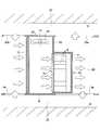
- FIG. 1is a simplified diagram showing an outline of the air conditioning system according to the first embodiment.
- the air conditioning system shown in FIG. 1is an air conditioning system that circulates air in order to cool electronic devices in a rack in a computer room in which a rack in which electronic devices such as ICT devices are accommodated.
- the rack 2accommodates a plurality of electronic devices 4 stacked.
- the front surface 2 a of the rack 2is open, and air on the front surface side can be taken into the rack 2.
- the air taken into the rack 2is sucked into the electronic device 4 in the rack 2, cooled inside the electronic device 4, and then discharged from the rear side of the electronic device 4.
- the air discharged from the electronic device 4is discharged outside the rack 2 through the opening on the rear surface 2b side of the rack.
- Such an air flow flowing from the front surface 2 a to the rear surface 2 b of the rack 2is generated by a cooling fan provided inside the electronic device 4 accommodated in the rack 2, and is generated inside the electronic device 4. There is no blower in particular other than the provided cooling fan.
- Rack 2is installed on the floor board 6 of the computer room. In general, a plurality of racks 2 are arranged side by side. In FIG. 1, it is assumed that a plurality of racks 2 are aligned in a direction perpendicular to the paper surface to form a rack row.
- An air flow pathis formed between the floor board 6 and the slab 8 of the building constituting the computer room. This underfloor air flow path is commonly referred to as an underfloor plenum. That is, an underfloor plenum 10 is formed between the floor board 6 and the slab 8.
- An opening 6 ais provided in the floor board 6, so that air can flow into the underfloor plenum 10 from the upper side of the floor board 6, and air can flow out of the underfloor plenum 10 to the upper side of the floor board 6.
- a flat plate heat exchanger 12is installed in a state of facing the opening of the front surface 2a.
- the front surface 2a side of the rack 2is a maintenance area in which a person performs work to perform maintenance / inspection of the electronic device 4, and the front-side maintenance space 14 is provided between the heat exchanger 12 and the front surface 2a of the rack 2. Is formed.
- the heat exchanger 12extends vertically from the floor plate 6 to a position higher than the height of the rack 2 and is part of a wall that forms the front-side maintenance space 14.
- the heat exchanger 12is provided with a pipe through which a coolant such as cooling water flows, and a pump through which the refrigerant flows is connected to the pipe.
- the heat exchanger 12will be described later.
- the partition wall 16extends vertically upward from the top of the front surface 2a of the rack 2 and extends horizontally at the same height as the heat exchanger 12, and is connected to the top of the heat exchanger 12. Although not shown in FIG. 1, the partition wall 16 extends from the side surface of the rack 2 to the side portion of the heat exchanger 12 (extends parallel to the paper surface of FIG. 1). Therefore, a closed space (closed space) is formed by the front surface 2 a of the rack 2, the flat plate heat exchanger 12, and the partition wall 16, and this space corresponds to the front-side maintenance space 14. A door is provided at a portion of the partition wall 16 parallel to the paper surface of FIG. 1 so that an operator can enter and exit the front-side maintenance space 14.
- the electronic device 4 in the rack 2sucks air from the front surface 2a side of the rack 2 and discharges it to the rear surface 2b side of the rack 2. That is, the electronic device 4 sucks air in the front-side maintenance space 14 that is a closed space through the opening of the front surface 2 a of the rack 2 and discharges it to the rear surface 2 b side of the rack 2. Therefore, the front side maintenance space 14 has a negative pressure, and the air outside the front side maintenance space 14 flows into the front side maintenance space 14 through the heat exchanger 12. At this time, the air flowing into the front-side maintenance space 14 is cooled when passing through the heat exchanger 12 and becomes low-temperature air (low-temperature air). The only part where air can flow into the front side maintenance space 14 is the heat exchanger 12, and only the air cooled to the low temperature by the heat exchanger 12 flows into the front side maintenance space 14.
- the air taken in by the electronic device 4 in the rack 2is low-temperature air in the front-side maintenance space 14, and the components in the electronic device 4 can be efficiently cooled.
- the heat exchanger 12forms a wall of the front side maintenance space 14 and its area is large, so that the pressure loss when the air flowing into the front side maintenance space 14 passes through the heat exchanger 12 is small. For this reason, it is not necessary to provide a special blower in order to allow air to flow into the front-side maintenance space 14 or to let air flow out of the front-side maintenance space 14, but only the air suction action of the electronic device 4 itself in the rack 2. Thus, air can be introduced into the front-side maintenance space 14 through the heat exchanger 12. Since the height of the heat exchanger 12 is higher than the height of the rack 2, the area of the heat exchanger 12 through which air passes can be made sufficiently larger than the area of the rear surface 2 b of the rack 2. For this reason, compared with the case where a heat exchanger is provided on the rear surface 2b of the rack 2, the pressure loss in the heat exchanger can be sufficiently reduced.
- a heat insulating material 18is provided on the inner surface of the heat exchanger 12 and the portion other than the front surface 2a of the rack 2 (the inner surface and the floor surface of the partition wall 16). It may be pasted. Or partition 16 itself can also be formed with the material which has favorable heat insulation.
- the upper space in the computer roomalso forms an air flow path for returning the high-temperature air discharged from the rear surface 2 b of the rack 2 to the intake side of the heat exchanger 12.
- air (high-temperature air) discharged from the rack 2is air discharged from the electronic device 4, and the temperature may vary depending on the amount of heat absorbed inside the electronic device 10. That is, the high-temperature air discharged from the rack 2 may not be a uniform temperature. Even in such a case, the high-temperature air is mixed while flowing through the rear-side maintenance space 60 and the above-described air flow path, so that the air has a uniform temperature overall. For this reason, air of the same temperature can be supplied to the entire intake surface of the heat exchanger 12, and the temperature of the air flowing into the front-side maintenance space 14 through the heat exchanger 12 is also a constant temperature with no overall variation. It becomes.
- the heat exchanger 12that increases the area and reduces the pressure loss as much as possible is provided on the intake side of the rack 2, so that only the fan provided in the electronic device 4 can be used. Run air. That is, the power for passing air through the heat exchanger 12 is borne by the fan mounted on the electronic device 4 for cooling the internal components. For this purpose, it is necessary that the static pressure to be raised to allow air to pass through the heat exchanger 12 is sufficiently smaller than the static pressure to be raised to allow air to pass inside the electronic device 4.
- the pressure loss of the heat exchanger 12is large, assuming that the performance of the fan mounted on the electronic device 4 is constant, the static pressure raised by the fan of the electronic device 4 becomes large, and the amount of air passing through the fan becomes large. The amount of air flowing through the electronic device 4 decreases. When the amount of air flowing through the electronic device 4 is reduced, the cooling action is weakened, and the temperature of components inside the electronic device 4 is increased, which may impair the operation and reliability of the electronic device 4.
- the pressure loss of the heat exchanger 12is made sufficiently small so that the amount of air flowing through the electronic device 4 hardly changes.
- the static pressure that the fan inside the electronic device 4 raises to carry airis several hundred Pa. Therefore, if the pressure loss of the heat exchanger 12 is, for example, 5 Pa or less, the decrease in the amount of air flowing through the electronic device 4 is several percent, and the effect on the cooling action of the components in the electronic device 4 can be almost eliminated. it can.
- Cis a coefficient and V is the air flow rate.
- Xvaries depending on the shape of the resistor, but may be considered to be substantially constant.
- C and Vshould be reduced.
- the area of the heat exchanger 12may be increased. If the area of the heat exchanger 12 is increased, the thickness required for the heat exchanger 12 can be reduced, and C (coefficient) can be reduced by making the heat exchanger 12 thinner.
- the plate-like heat exchanger 12 having a large areais provided on the intake surface side of the rack 2 so as to extend in the vertical direction.
- FIG. 2is a simplified diagram showing an example in which the above-described air conditioning system is provided in a computer room having a ceiling duct. 2, parts that are the same as the parts shown in FIG. 1 are given the same reference numerals, and descriptions thereof will be omitted.
- the ceiling plate 20 of the computer roomis used as a part extending horizontally of the partition wall 16. Accordingly, the partition wall 16 extends from the front surface 2 a of the rack 2 to the ceiling plate 20. Further, the heat exchanger 12 also extends to the ceiling board 20. As described above, in the example illustrated in FIG. 2, the front-side maintenance space 14 is formed by the front surface 2 a of the rack 2, the heat exchanger 12, the partition wall 16, and the ceiling plate 20.
- a ceiling duct 22is formed between the ceiling plate 20 and the slab 8 on the ceiling side.
- the ceiling board 20has an opening 20 a as with the floor board 6. A part of the high-temperature air discharged from the rack 2 flows into the ceiling duct 22 formed between the ceiling plate 20 and the slab 8 in the computer room through the opening 20 a of the ceiling plate 20.
- the high-temperature air that has flowed into the ceiling duct 22flows toward the intake side of the heat exchanger 12, and exits under the ceiling plate 20 from the opening 20 a of the ceiling plate 20 provided on the intake side of the heat exchanger 12.
- the ceiling duct 22forms an air flow path for returning the high-temperature air discharged from the rear surface 2b of the rack 2 to the intake side of the heat exchanger 12.
- FIG. 3is a simplified diagram showing an example in which a low temperature air mixing promotion mechanism is provided in the air conditioning system shown in FIG. 3, parts that are the same as the parts shown in FIG. 2 are given the same reference numerals, and descriptions thereof will be omitted.
- the low-temperature air mixing promotion mechanismcorresponds to the air stirring fan 24 attached to the ceiling board 20 in the front-side maintenance space 14.
- the fan 24is provided for appropriately stirring and mixing the air in the front-side maintenance space 14 that is a closed space. Therefore, unlike the fan for blowing air, the fan 24 does not need to generate a strong air flow, and a fan with a small output is sufficient.
- the temperature of the low-temperature air sucked from the front surface 2a of the rack 2can be made more uniform. Thereby, the air of uniform temperature can be supplied with respect to each of the some electronic device 4 accommodated in the rack 2, and a cooling nonuniformity can be eliminated.
- the front-side maintenance space 14also serves as a low-temperature air mixing space that mixes low-temperature air to make air of uniform temperature.
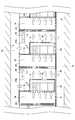
- FIG. 4is a simplified diagram showing an air conditioning system in which a plurality of configurations combining the row of racks 2 and the front-side maintenance space 14 shown in FIG. 3 are formed. 4, parts that are the same as the parts shown in FIG. 3 are given the same reference numerals, and descriptions thereof will be omitted.
- the heat exchanger 12 that forms the front-side maintenance space 14 of the rack 2 in the adjacent rowis disposed on the rear surface 2 b side of the rack 2.
- the air discharged from the rear surface 2b of the rack 2can flow to the ceiling duct 22 on the ceiling side and the underfloor plenum 10 below the floor. Since it is considered that there are a plurality of forms of FIG. 3 as the air flow, the air flow of FIG. 3 is formed.
- a part of the air exhausted from the rear surface 2b of the rack 2passes through the heat exchanger 12 forming the front side maintenance space 14 of the rack 2 in the next row and passes through the front side maintenance space of the rack 2 in the next row. 14 can also be considered. In this case, the high-temperature air moves through the underfloor plenum 10 and the ceiling duct 22 over the rack row.
- FIG. 5is a schematic diagram of the air conditioning system shown in FIG. 4 provided in a computer room having no ceiling duct. 5, parts that are the same as the parts shown in FIG. 4 are given the same reference numerals, and descriptions thereof will be omitted.
- the air conditioning system shown in FIG. 5has the same configuration as the air conditioning system shown in FIG. 4 except that the computer room has no ceiling duct. Most of the high-temperature air discharged from one row of the rack 2 passes through the heat exchanger 12 provided for the next row of the rack 2 and enters the front-side maintenance space 14. For this reason, it is sufficient that the other air flow path has the underfloor plenum 10 under the floor, and it is not necessary to provide a ceiling duct.
- FIG. 6is a simplified diagram showing the air conditioning system shown in FIG. 4 provided with a high-temperature air mixing promotion mechanism. 6, parts that are the same as the parts shown in FIG. 4 are given the same reference numerals, and descriptions thereof will be omitted.
- an air agitating fan 24is provided in the front side maintenance space 14, and the low temperature air in the front side maintenance space 14 is agitated and mixed by the fan 24 to obtain air of uniform temperature.
- an air agitating fan 26is provided as a high-temperature air mixing promotion mechanism not in the front-side maintenance space 14 but in a space in which high-temperature air on the rear surface 2 b side of the rack 2 flows.
- the high-temperature air discharged to the rear surface 2b side of the rack 2is air discharged from the plurality of electronic devices 4 in the rack 2, and there is a possibility that the temperature of the air discharged varies depending on the operation status of the electronic devices 4. is there. Therefore, in the example shown in FIG. 6, the fan 26 is provided in the space on the rear surface 2 b side of the rack 2, and the high-temperature air discharged to the rear surface 2 b side of the rack 2 is stirred and mixed by the fan 26. Pass through. Thereby, the air cooled by passing through the heat exchanger 12 can be set to a uniform temperature as a whole, and low-temperature air having a uniform temperature can be supplied to each of the plurality of electronic devices 4.
- FIG. 7is a simplified diagram showing the air conditioning system shown in FIG. 5 provided with a high-temperature air mixing promotion mechanism. 7, parts that are the same as the parts shown in FIG. 5 are given the same reference numerals, and descriptions thereof will be omitted.
- an air agitating fan 24is provided in the front side maintenance space 14, and the low temperature air in the front side maintenance space 14 is agitated and mixed by the fan 24 to obtain air of uniform temperature.
- an air agitating fan 26is provided as a high-temperature air mixing promotion mechanism not in the front-side maintenance space 14 but in a space in which high-temperature air on the rear surface 2 b side of the rack 2 flows.
- the high-temperature air discharged to the rear surface 2b side of the rack 2is air discharged from the plurality of electronic devices 4 in the rack 2, and there is a possibility that the temperature of the air discharged varies depending on the operation status of the electronic devices 4. is there. Therefore, in the example shown in FIG. 7, the fan 26 is provided in the space on the rear surface 2b side of the rack 2, and the high temperature air discharged to the rear surface 2b side of the rack 2 is stirred and mixed by the fan 26, and then the heat exchanger 12. Pass through. Thereby, the air cooled by passing through the heat exchanger 12 can be set to a uniform temperature as a whole, and low-temperature air having a uniform temperature can be supplied to each of the plurality of electronic devices 4.
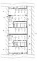
- FIG. 8is a simplified diagram showing an air conditioning system in which a high-temperature space is provided on the rear surface 2b side of the rack 2.
- FIG. 8parts that are the same as the parts shown in FIG. 4 are given the same reference numerals, and descriptions thereof will be omitted.
- the air conditioning system shown in FIG. 8is the same as the air conditioning system shown in FIG. 4 except that the fan 24 is not provided in the front side maintenance space 14 and a rack partition plate 28 is provided instead.
- the rack partition plate 28is disposed between the rear surface 2a of the rack 2 and the heat exchanger 12 facing the rack 2 and extends vertically from the floor plate 6 to the ceiling plate 20.
- a high-temperature air space 30is formed between the rear surface 2b of the rack 2 and the rack partition plate 28, and high-temperature air is discharged, and high-temperature air is supplied between the rack partition plate 28 and the intake surface 12a of the heat exchanger 12.
- a hot air space 32is formed.
- the hot airflows through the underfloor plenum 10 and the ceiling duct 22 and flows into the hot air space 32. Thereafter, the high-temperature air passes through the heat exchanger 12 from the high-temperature air space 32 and is cooled to flow into the front-side maintenance space 14 as low-temperature air.
- the high-temperature air flowing through the heat exchanger 12flows into the high-temperature air space 32 after passing through the underfloor plenum 10 or the ceiling duct 22. Is stirred and mixed to obtain a uniform temperature. Therefore, even if the air stirring fan 26 is not particularly provided, the high temperature air can be made to have a uniform temperature. Therefore, the underfloor plenum 10 and the ceiling duct 22 function as a high-temperature air mixing path.
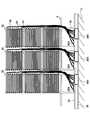
- FIG. 9is a perspective view showing the front side maintenance space 14 shown in FIG. 1 formed between the heat exchanger 12 and the row of racks 2.
- FIG. 10is an enlarged perspective view showing only the heat exchanger 12.
- the flat plate heat exchanger 12 shown in FIGS. 9 and 10includes a plurality of heat exchanger modules 30 and a plurality of frames 32. A plurality of heat exchanger modules 30 are attached to one frame 32, and a plurality of frames 32 are connected to form a flat plate heat exchanger 12 in which the heat exchanger modules 30 are arranged in a matrix. Is done.
- Cooling wateris supplied as a refrigerant to each of the heat exchanger modules 30, and each of the heat exchanger modules 30 can individually cool the air passing through the heat exchanger module 30.
- the heat exchanger 12may be formed by one large heat exchanger module, the temperature of the cooling water changes between the supply side and the discharge side of the cooling water, and the entire heat exchanger 12 is uniformly cooled. May not be possible. Therefore, in the heat exchanger 12 shown in FIGS. 9 and 10, a plurality of small heat exchanger modules 30 are connected to form a single heat exchanger 12, and each heat exchanger module 30 is individually provided. Cooling water is supplied to
- FIG. 11is a side view showing a state in which piping for supplying cooling water to the heat exchanger 12 is connected.
- a gantry 34is installed on the slab 8 under the floor of the computer room, and a frame 32 to which a plurality of heat exchanger modules 30 are attached is fixed on the gantry 34.
- a cooling water supply side pipe 36 and a return side pipe 38are provided on the slab 8 under the floor.
- a supply side manifold 36Ais provided in the middle of the supply side pipe 36.
- a return side manifold 38Ais provided in the middle of the return side pipe 38.
- a cooling water supply pipe 40 extending from one supply side manifold 36Ais connected to each of the heat exchanger modules 30 attached to one frame 32, and cooling extending from one return side manifold 38A is connected.
- a water return pipe 42is connected. Therefore, the low-temperature cooling water flowing through the supply side pipe 36 flows from the supply side manifold 36 ⁇ / b> A through the cooling water supply pipe 40 and is supplied to one heat exchanger module 30. While the low-temperature cooling water flows through the heat exchanger module 30, the passing air is cooled to become high-temperature cooling water. The high-temperature cooling water is discharged to the cooling water return pipe 42 and flows to the return side pipe 38 via the return side manifold 38A.
- FIG. 13shows the cooling water circulation circuit shown in FIG.
- the supply side pipe 36 and the return side pipe 38are connected to a cold water production apparatus 46.
- the cold water production apparatus 46includes a pump and a heat exchanger, cools the high-temperature cooling water flowing from the return side pipe 38 into low-temperature cooling water, and sends it to the supply side pipe 36.
- Each of the cooling water pumps 44pumps low-temperature cooling water from the supply side pipe 36 and supplies it to the heat exchanger module 30.
- the low-temperature cooling watercools the air to become high-temperature cooling water, and is discharged to the return side pipe 38.
- an air temperature sensor 50may be provided in each of the heat exchanger modules 30, and the flow rate of the cooling water supplied may be controlled based on the temperature of the air passing through the heat exchanger module 30.
- the air temperature sensor 50is provided on the intake side of the heat exchanger module 30 and detects the temperature of hot air entering the heat exchanger module 30.
- FIG. 15is a circuit diagram of a cooling water circulation system capable of controlling the cooling water flow rate to each heat exchanger module 30. 15, parts that are the same as the parts shown in FIG. 13 are given the same reference numerals, and descriptions thereof will be omitted.
- the temperature detection value from the air temperature sensor 50 provided in each of the heat exchanger modules 30is sent to the controller 52.
- the temperature detection value from the air temperature sensor 50is the temperature value of the high-temperature air entering each heat exchanger module 30.
- the controller 52controls each cooling water pump 44 based on the temperature detection value from the air temperature sensor 50 to adjust the flow rate of the cooling water.
- the controller 52supplies the cooling water for supplying the cooling water to the heat exchanger module 30.
- the flow rate of the pump 44is increased.
- action of the said heat exchanger module 30becomes large, and the temperature of the air which passed the said heat exchanger module 30 can be made the same as the temperature of the air which passed the other heat exchanger module 30. .
- FIG. 16is a schematic diagram showing an air conditioning system having the heat exchanger 12 formed by the heat exchanger module 30 provided with the fan 30a.
- the fan 30amay have an output capable of recovering the small pressure loss of the heat exchanger module 30, and a low-power consumption fan with a low rotation speed is sufficient. Further, since the effect of stirring and mixing the low-temperature air is produced, the fan 30a of each heat exchanger module 30 is substituted for the air stirring fan 24 shown in FIG.
Landscapes
- Engineering & Computer Science (AREA)
- General Engineering & Computer Science (AREA)
- Computer Hardware Design (AREA)
- Physics & Mathematics (AREA)
- Thermal Sciences (AREA)
- Microelectronics & Electronic Packaging (AREA)
- Chemical & Material Sciences (AREA)
- Combustion & Propulsion (AREA)
- Mechanical Engineering (AREA)
- Cooling Or The Like Of Electrical Apparatus (AREA)
Abstract
Description
Translated fromJapanese実施形態は電算機室等に用いられる空調システムと電算機が発する排気を冷却する熱交換器に関する。Embodiments relate to an air conditioning system used in a computer room or the like and a heat exchanger that cools exhaust gas generated by the computer.
企業で用いられるサーバ、ストレージシステム、ネットワーク機器などのICT機器(情報通信機器)は、電算機室(データセンタやマシンルームあるいはサーバルームと称される部屋又は空間)に設置されることが多い。ここではそのような電算機室をデータセンタと称することとする。サーバ、ストレージシステム、ネットワーク機器などのICT機器は、通常、ICT機器搭載ラック(以下、単にラックと称する)に収容される。データセンタにはラックが整列して配置される。ICT devices (information communication devices) such as servers, storage systems, and network devices used in companies are often installed in computer rooms (rooms or spaces called data centers, machine rooms, or server rooms). Here, such a computer room is referred to as a data center. ICT devices such as servers, storage systems, and network devices are usually housed in ICT device mounting racks (hereinafter simply referred to as racks). Racks are aligned in the data center.
ICT機器はCPUやその他の機能部品を有しており、機能部品が動作する際に電力を消費し発熱する。したがって、ICT機器の正常な動作を保証するために、あるいは動作の信頼性を確保するためには、機能部品を一定温度以下に維持する必要がある。そのため、ICT機器にはファンなどの空気流発生部品が組み込まれており、強制空冷などで機能部品を冷却することが一般的である。ICT equipment has a CPU and other functional parts, and consumes power and generates heat when the functional parts operate. Therefore, in order to ensure the normal operation of the ICT device or to ensure the reliability of the operation, it is necessary to maintain the functional component at a certain temperature or lower. For this reason, air flow generating parts such as fans are incorporated in ICT equipment, and functional parts are generally cooled by forced air cooling or the like.
一般的なICT機器は、ICT機器の空気吸い込み口から一定温度以下の空気を吸い込むことを前提としており、吸い込む空気の上限温度が動作保証温度として定められている。データセンタでは,一定の空間(部屋)に多数のICT機器が設置されるため、空調による温度制御を行なわないと、ICT機器の発熱によって空間(部屋)内の空気の温度が過度に上昇してしまうおそれがある。そこで、ICT機器が設置されるデータセンタでは、空間(部屋)内の温度がIT機器の動作保証温度を越えないように、 同一の空間(部屋)あるいは別に設けられた部屋(空間)に空調システムを設置することが一般的である。空調システムは、ICT機器設置エリアの雰囲気に放出された熱を、屋外などのICT機器設置エリア外に放出することで、ICT機器が設置された空間(部屋)の温度を一定の温度に維持する。General ICT equipment is based on the premise that air below a certain temperature is sucked from the air suction port of the ICT equipment, and the upper limit temperature of the sucked air is set as the guaranteed operating temperature. In a data center, since a large number of ICT devices are installed in a certain space (room), the temperature of air in the space (room) rises excessively due to heat generated by the ICT devices unless temperature control is performed by air conditioning. There is a risk that. Therefore, in a data center where ICT equipment is installed, an air conditioning system is installed in the same space (room) or in a separate room (space) so that the temperature in the space (room) does not exceed the guaranteed operating temperature of the IT equipment. It is common to install. The air conditioning system maintains the temperature of the space (room) where the ICT equipment is installed at a constant temperature by releasing the heat released to the atmosphere of the ICT equipment installation area outside the ICT equipment installation area such as outdoors. .
空調システムは、ICT機器が設置された空間(部屋)内の空気を循環させながら、熱を外部に放出する。すなわち、空調システムの空調機から出てくる比較的低温の空気はICT機器搭載ラックの空気吸い込み口に供給される。その比較的低温の空気は、ICT機器が内蔵しているファンなど空気流発生部品によりICT機器内に取り込まれる。それによってICT機器内のCPUやその他機能部品が冷却される。ICT機器内の機能部品から熱を奪って比較的高温となった空気は、ICT機器の排気口から放出される。放出された空気は速やかに空調システムの吸気口に戻り、空調機内に取り込まれ、そこで取り込まれた空気から熱が放出されて低温の空気となり、再び空調機から吹き出される。The air conditioning system releases heat to the outside while circulating the air in the space (room) where the ICT equipment is installed. That is, the relatively low temperature air coming out of the air conditioner of the air conditioning system is supplied to the air suction port of the rack mounted with the ICT equipment. The relatively low temperature air is taken into the ICT device by an air flow generating component such as a fan built in the ICT device. As a result, the CPU and other functional components in the ICT equipment are cooled. The air that has taken heat from the functional parts in the ICT device and has become relatively hot is discharged from the exhaust port of the ICT device. The released air quickly returns to the air inlet of the air conditioning system and is taken into the air conditioner, where heat is released from the taken air to become low-temperature air, and is blown out from the air conditioner again.
一般的に、データセンタなどの電算機室には、多数のICT機器を搭載したラックが整列して配置される。電算機室の床下には、空調機から吹き出された低温の空気が流れる空間が設けられている(この空間を床下プレナムと称する)。電算機室の床には開口部が設けられており、床下プレナムを流れる低温の空気は開口部から床上に流れ出る。開口部は床上に配置されたラックの空気吸い込み口の近傍に設けられており、開口部から床上に流れ出た低温の空気は、ラック内に吸い込まれる。ラックの空気吸い込み口は、一般的にラックの前面に設けられており、空気吸い込み口から吸い込まれた空気はラック内のICT機器内にさらに吸い込まれて内部を冷却してからラック内に排出される。ICT機器からICT機器搭載ラック内に排出された空気は熱を吸収して暖まっている。そして、ラック内に排出された暖まった空気は、ラックの背面に設けられた空気排気口から電算機室内に排出される。暖まった空気は上方に流れ、電算機室の天井に沿って横に流れて空調機に吸い込まれ、空調機で冷却された再び低温の空気となって、空調機から床下の空間に吹き出される。Generally, in a computer room such as a data center, racks equipped with a large number of ICT devices are arranged side by side. A space through which low-temperature air blown from the air conditioner flows is provided under the floor of the computer room (this space is referred to as an underfloor plenum). An opening is provided in the floor of the computer room, and low-temperature air flowing through the underfloor plenum flows out from the opening onto the floor. The opening is provided in the vicinity of the air suction port of the rack disposed on the floor, and the low-temperature air flowing out from the opening onto the floor is sucked into the rack. The air inlet of the rack is generally provided at the front of the rack, and the air sucked from the air inlet is further sucked into the ICT equipment in the rack, cooled inside, and then discharged into the rack. The The air discharged from the ICT device into the ICT device mounting rack absorbs heat and is warmed. And the warm air discharged | emitted in the rack is discharged | emitted in the computer room from the air exhaust port provided in the back surface of the rack. Warm air flows upward, flows sideways along the ceiling of the computer room, is sucked into the air conditioner, becomes cold air again cooled by the air conditioner, and blows out from the air conditioner to the space under the floor .
以上のような構成の空調システムでは、ラックの後面側から排出される暖かいは電算機室の空調機で冷却されて低温の空気となり、再び多数のラックの前面側に送り込まれて、ラック内のIT機器に吸い込まれる。このような空調システムでは、多数のラックから排出される空気の全てを、電算機室の空調機のみで一括して冷却して、再びラックに送る必要がある。電算機室の空調機に搭載された熱交換器は小型であり、圧力損失が高いものが多い。この場合、空調機は多数のラックに対して多量の空気を送風しなければならないので、高出力のブロア(送風機)を空調機に設ける必要がある。このような高出力のブロアは電力消費が大きいため、空調機の運転に必要な電力が増大し、空調システムの冷却効率が低下してしまう。In the air conditioning system configured as described above, the warm air discharged from the rear side of the rack is cooled by the air conditioner in the computer room to become low-temperature air, and is sent again to the front side of many racks. Inhaled by IT equipment. In such an air conditioning system, it is necessary to cool all of the air discharged from a large number of racks at a time using only the air conditioner in the computer room, and send the air again to the rack. Many heat exchangers installed in air conditioners in computer rooms are small and have high pressure loss. In this case, since the air conditioner must blow a large amount of air to a large number of racks, it is necessary to provide a high output blower (blower) in the air conditioner. Since such a high-output blower consumes a large amount of power, the power required to operate the air conditioner increases and the cooling efficiency of the air conditioning system decreases.
そこで、個々のラックの排気側に熱交換機設け、ラック内の機器から排出される空気を直ちに冷却してラック外に排出する方法が提案されている(例えば、特許文献1参照。)。Therefore, a method has been proposed in which a heat exchanger is provided on the exhaust side of each rack, and the air discharged from the equipment in the rack is immediately cooled and discharged outside the rack (for example, see Patent Document 1).
個々のラックの後面側に熱交換器を設ける場合、ラックの後側全面を用いて比較的大きな面積である上に、多数の熱交換器を設けることができ、大きな面積を確保することができる。したがって、複数のラックから排出される高温の空気を冷却する空調機に内蔵される熱交換器の圧力損失より個々のラック背面に設置した熱交換器では圧力損失を小さくすることができる。ただし、この場合であっても、熱交換器を設けることのできる面積は、ラックの後面側の面積に限られ、それ以上大きな面積とすることはできない。When a heat exchanger is provided on the rear side of each rack, a large area can be provided in addition to a relatively large area using the whole rear side of the rack, and a large area can be secured. . Therefore, the pressure loss can be reduced in the heat exchangers installed on the back surfaces of the individual racks than the pressure loss of the heat exchanger built in the air conditioner that cools the high-temperature air discharged from the plurality of racks. However, even in this case, the area where the heat exchanger can be provided is limited to the area on the rear surface side of the rack and cannot be larger than that.
また、ラックに個別に熱交換器を設けて排気を冷却することとなるので、搭載されたICT機器のそれぞれから排出される空気の温度や空気流速は異なっており、熱交換器で除去できる熱量にばらつきが生じてしまう。Also, since the exhaust is cooled by installing a heat exchanger individually in the rack, the temperature and air flow rate of air discharged from each of the mounted ICT devices are different, and the amount of heat that can be removed by the heat exchanger Variation will occur.
そこで、空調機に高出力の送風機を備えること無く、ICT機器自体が有する送風機(冷却ファン)の送風により、ラック内のICT機器の冷却に必要な空気流を得ることができる空調システムの開発が望まれている。Therefore, the development of an air conditioning system that can obtain an air flow necessary for cooling the ICT equipment in the rack by blowing air from the blower (cooling fan) of the ICT equipment itself without providing a high-power blower in the air conditioning equipment. It is desired.
実施形態によれば、電子機器を収容し、その前面側から吸気して後面側から排気するラックと、該ラックの前面に対向して配置された平板状の熱交換器とを有し、該熱交換器と該ラックの前面との間に、所定の閉空間が形成され、該ラックの後面側に排出された空気が該所定の閉空間を通らずに該熱交換器の吸気側に流れる空気流路が形成された空調システムが提供される。According to the embodiment, the electronic apparatus includes a rack that sucks air from the front side and exhausts air from the rear side, and a flat plate-shaped heat exchanger that is disposed to face the front surface of the rack, A predetermined closed space is formed between the heat exchanger and the front surface of the rack, and the air discharged to the rear surface side of the rack flows to the intake side of the heat exchanger without passing through the predetermined closed space. An air conditioning system in which an air flow path is formed is provided.
実施形態によれば、熱交換器の面積を大きくとることができ、熱交換器の圧力損失を低減することができる。これにより、空調機に高出力の送風機を備えること無く、電子機器自体が有する送風機(冷却ファン)の送風により、ラック内の電子機器医の冷却に必要な空気流を得ることができるAccording to the embodiment, the area of the heat exchanger can be increased, and the pressure loss of the heat exchanger can be reduced. Thereby, without providing a high output blower in the air conditioner, it is possible to obtain an air flow necessary for cooling the electronic device doctor in the rack by blowing air from the blower (cooling fan) of the electronic device itself.
次に、実施形態について図面を参照しながら説明する。Next, embodiments will be described with reference to the drawings.
図1は第1実施形態による空調システムの概要を示す簡略図である。図1に示す空調システムは、例えばICT機器等の電子機器が収容されたラックが設置された電算機室において、ラック内の電子機器を冷却するために空気を循環させる空調システムである。FIG. 1 is a simplified diagram showing an outline of the air conditioning system according to the first embodiment. The air conditioning system shown in FIG. 1 is an air conditioning system that circulates air in order to cool electronic devices in a rack in a computer room in which a rack in which electronic devices such as ICT devices are accommodated.
ラック2は複数の電子機器4を積み重ねた状態で収容する。ラック2の前面2aは開口しており、前面側の空気をラック2内に取り込むことができる。ラック2内に取り込まれた空気は、ラック2内の電子機器4内に吸い込まれ、電子機器4内を冷却してから、電子機器4の後側から排出される。電子機器4から排出された空気は、ラックの後面2b側の開口を通じて、ラック2の外部に排出される。このようなラック2の前面2aから後面2bへと流れる空気流は、ラック2の内部に収容された電子機器4の内部に設けられた冷却ファンにより発生するものであり、電子機器4の内部に設けられた冷却ファン以外に特に送風機は設けられていない。The
ラック2は電算機室の床板6に設置されている。一般的に複数のラック2が整列して配置される。図1では、紙面に垂直な方向に複数のラック2が整列してラック列が形成されているものとする。床板6と電算機室を構成する建物のスラブ8との間には、空気流路が形成される。この床下の空気流路は、一般的に床下プレナムと称される。すなわち、床板6とスラブ8との間に床下プレナム10が形成される。床板6には開口6aが設けられており、床板6の上側から床下プレナム10に空気が流入することができ、また、床下プレナム10から空気が床板6の上側に流出することができる。
床板6に設置されたラック2の前面2a側には、前面2aの開口に対向した状態で、平板状の熱交換器12が設置されている。ラック2の前面2a側は、電子機器4の保守・点検を行なうために人が作業を行なう保守エリアとなっており、熱交換器12とラック2の前面2aとの間に前面側保守空間14が形成される。熱交換器12は、床板6からラック2の高さより高い位置まで垂直に延在し、前面側保守空間14を形成する壁の一部となっている。On the
なお、熱交換器12には、冷却水等の冷媒が流れる管路が設けられ、この管路には冷媒を流すポンプが接続されている。熱交換器12については後述する。The
ラック2の前面2aの頂部から隔壁16が垂直上方に向かって延在し、熱交換器12と同じ高さとなったところで、水平に延在し、熱交換器12の上部に接続されている。また、図1には現れていないが、隔壁16はラック2の側面から熱交換器12の側部まで延在している(図1の紙面に平行に延在する)。したがって、ラック2の前面2aと、平板状の熱交換器12と、隔壁16とにより、閉じた空間(閉空間)が形成され、この空間が前面側保守空間14に相当する。なお、隔壁16の図1の紙面に平行な部分には、作業者が前面側保守空間14に出入りできるように、ドアが設けられる。The
ラック2内の電子機器4は、ラック2の前面2a側から空気を吸い込み、ラック2の後面2b側に排出する。すなわち、電子機器4は、ラック2の前面2aの開口を通じて、閉空間である前面側保守空間14内の空気を吸い込み、ラック2の後面2b側に排出する。したがって、前面側保守空間14は負圧となり、前面側保守空間14の外側の空気が熱交換器12を通じて前面側保守空間14に流入する。この際、前面側保守空間14に流入する空気は、熱交換器12を通る際に冷却されて低温の空気(低温空気)となる。前面側保守空間14に空気が流入できる部分は熱交換器12だけであり、熱交換器12で冷却されて低温となった空気のみが前面側保守空間14に流入する。The
したがって、ラック2内の電子機器4が吸入する空気は、前面側保守空間14内の低温の空気であり、電子機器4内の部品を効率的に冷却することができる。Therefore, the air taken in by the
熱交換器12は前面側保守空間14の壁を形成しており、その面積は大きいので、前面側保守空間14に流入する空気が熱交換器12を通過する際の圧力損失は小さい。このため、前面側保守空間14に空気を流入させるため、あるいは前面側保守空間14から空気を流出させるために特別に送風機を設ける必要はなく、ラック2内の電子機器4自体の空気吸入作用だけで、熱交換器12を通して前面側保守空間14内に空気を流入させることができる。熱交換器12の高さは、ラック2の高さより高いため、熱交換器12の空気が通過する部分の面積を、ラック2の後面2bの面積より十分大きくすることができる。このため、ラック2の後面2bに熱交換器を設ける場合に比較して、熱交換器での圧力損失を十分に小さくすることができる。The
また、熱交換器12の冷却作用が部分的に異なっていた場合などで、前面側保守空間14内に流入する空気の温度が一様でなかったとしても、熱交換器12を通じて流入した空気がラック2の前面2aに到達するまでに、異なる温度の空気は混合される。ラック2の前面2aの開口から電子機器4に吸入される空気は、一様な低温の空気(低温空気)となっており、電子機器4の各々に対して一定の低温の空気を供給することができる。このため、吸入空気の温度むらが原因で電気機器4に対する冷却効果が異なるといった問題を防止することができる。Even if the cooling effect of the
なお、前面側保守空間14の内部の空気を低温の状態に維持するために、熱交換器12の内面とラック2の前面2a以外の部分(隔壁16の内面及び床面)に断熱材18を貼り付けておくこととしてもよい。あるいは、隔壁16自体を良好な断熱性を有する材料で形成することもできる。In order to maintain the air inside the front
ラック2内の電子機器4に吸入され、電子機器4の内部を冷却してから排出された空気(電子機器4内の熱を吸収して温まった空気(高温空気))は、ラック2の後面2bの開口から後面側保守空間60に排出される。ラック2から排出された高温空気の一部は、後面側保守空間60に設置された床板6の開口6aを通じて電算機室の床板6とスラブ8との間に形成された床下プレナム10に流入する。そして、床下プレナム10に流入した高温空気は、熱交換器12の吸気側に向かって流れ、熱交換器12の吸気側に設けられた床板6の開口6aから床板6の上に出る。このように、床下プレナム10は、ラック2の後面2bから排出された高温空気を熱交換器12の吸気側に戻す空気流路を形成する。Air sucked into the
また、ラック2から排出された高温空気の一部は、電算機室内でラック2及び隔壁16と天井のスラブ8との間の空間を流れて、熱交換器12の吸気側に戻る。したがって、電算機室内の上部空間も、ラック2の後面2bから排出された高温空気を熱交換器12の吸気側に戻す空気流路を形成する。Further, a part of the high-temperature air discharged from the
なお、ラック2から排出される空気(高温空気)は、電子機器4から排出される空気であり、電子機器10の内部での熱吸収量により温度が異なることがある。すなわち、ラック2から排出される高温空気は一様な温度ではないことがある。そのような場合でも、高温空気が後面側保守空間60や上述の空気流路を流れる間に混合され、全体的に一様な温度の空気となる。このため、同じ温度の空気を熱交換器12の吸気面全面に供給することができ、熱交換器12を通って前面側保守空間14に流れ込む空気の温度も全体的にばらつきのない一定の温度となる。Note that air (high-temperature air) discharged from the
上述のように、本実施形態による空調システムでは、面積を大きくして圧力損失を極力低減した熱交換器12をラック2の吸気側に設けることで、電子機器4に設けられたファンのみで、空気を流す。すなわち、熱交換器12に空気を通過させるための動力を電子機器4が内部の部品を冷却するために搭載しているファンに担わせている。このためには、電子機器4の内部に空気を通過させるために上昇させる静圧と比較して、熱交換器12に空気を通過させるために上昇させる静圧が十分に小さい必要がある。熱交換器12の圧力損失が大きい場合、電子機器4に搭載されたファンの性能が一定であると仮定すると、電子機器4のファンが上昇させる静圧が大きくなり、ファンを通過する空気量が減少し、電子機器4内を流れる空気量が減少してしまう。電子機器4内を流れる空気量が減少すると冷却作用が弱くなり、電子機器4内部の部品の温度が上昇して、電子機器4の動作や信頼性を損なうおそれがある。As described above, in the air conditioning system according to the present embodiment, the
そこで、本実施形態では、熱交換器12の圧力損失を十分小さくし、電子機器4内を流れる空気量がほとんど変化しないようにしている。電子機器4内部のファンが空気を搬送するために上昇させる静圧は数100Paである。したがって、熱交換器12の圧力損失が例えば5Pa以下であれば、電子機器4内を流れる空気量の減少は数%であり、電子機器4内の部品の冷却作用への影響をほとんどなくすことができる。Therefore, in the present embodiment, the pressure loss of the
一般的に空気の流れを阻害する抵抗体の圧力損失Pは以下の式で表される。Generally, the pressure loss P of the resistor that obstructs the air flow is expressed by the following equation.
P=C×VX(1.5~2.0)
上記の式中で、Cは係数であり、Vは空気流速である。Xは抵抗体の形状などで変化するが、ほぼ一定と考えて良い。圧力損失Pを小さくするためには、CとVを小さくすれば良いことがわかる。特にV(空気流速)を小さくすると1.5~2.0乗で効果を得ることができる。空気流速を小さくするためには、熱交換器12の面積を大きくすればよい。熱交換器12の面積を大きくすれば、熱交換器12に必要な厚さも小さくすることができ、熱交換器12を薄くすることでC(係数)も小さくなる。P = C × VX (1.5-2.0)
In the above equation, C is a coefficient and V is the air flow rate. X varies depending on the shape of the resistor, but may be considered to be substantially constant. In order to reduce the pressure loss P, it is understood that C and V should be reduced. In particular, when V (air flow velocity) is reduced, the effect can be obtained with a power of 1.5 to 2.0. In order to reduce the air flow rate, the area of the
電算機室において熱交換器12の面積を大きくとるためには、ラック2の吸気面がラック列に沿って大きくなることから、熱交換器12をラック列に沿って設置することが望ましい。ラック列に沿って熱交換器12を設置する場合、水平方向に延在するように設置する方法と垂直方向に延在するように設置する方法が考えられる。熱交換器12を水平方向に延在するように設置した場合、熱交換器12の面積をさらに大きくとろうとすると、設置面積が増える方向になるため望ましくない。また、熱交換器12を水平方向に延在するように設置した場合に、熱交換器12に結露が発生すると、水滴が前面側保守空間14の床面や床下のケーブル設置ゾーンに落ちるおそれがあり、好ましく無い。In order to increase the area of the
以上のような考察に基づいて、本実施形態では、ラック2の吸気面側に、板状で面積の大きい熱交換器12を垂直方向に延在するように設けたものである。Based on the above considerations, in this embodiment, the plate-
図2は、天井ダクトを有する電算機室に上述の空調システムを設けた例を示す簡略図である。図2において、図1に示す部品と同等な部品には同じ符号を付し、その説明は省略する。FIG. 2 is a simplified diagram showing an example in which the above-described air conditioning system is provided in a computer room having a ceiling duct. 2, parts that are the same as the parts shown in FIG. 1 are given the same reference numerals, and descriptions thereof will be omitted.
図2に示す空調システムでは、電算機室の天井板20を、隔壁16の水平に延在する部分として用いる。したがって、ラック2の前面2aから天井板20まで隔壁16が延在する。また、熱交換器12も、天井板20まで延在する。このように、図2に示す例では、ラック2の前面2aと、熱交換器12と、隔壁16と、天井板20とで、前面側保守空間14が形成される。In the air conditioning system shown in FIG. 2, the
また、天井板20と天井側のスラブ8との間に、天井ダクト22が形成される。天井板20は、床板6と同様に開口20aを有する。ラック2から排出された高温空気の一部は、天井板20の開口20aを通じて電算機室の天井板20とスラブ8との間に形成された天井ダクト22に流入する。そして、天井ダクト22に流入した高温空気は、熱交換器12の吸気側に向かって流れ、熱交換器12の吸気側に設けられた天井板20の開口20aから天井板20の下に出る。このように、天井ダクト22は、ラック2の後面2bから排出された高温空気を熱交換器12の吸気側に戻す空気流路を形成する。Also, a
図3は、図12に示す空調システムに低温空気混合促進機構が設けられた例を示す簡略図である。図3において、図2に示す構成部品と同等な部品には同じ符号を付し、その説明は省略する。FIG. 3 is a simplified diagram showing an example in which a low temperature air mixing promotion mechanism is provided in the air conditioning system shown in FIG. 3, parts that are the same as the parts shown in FIG. 2 are given the same reference numerals, and descriptions thereof will be omitted.
図3において、低温空気混合促進機構は、前面側保守空間14内で天井板20に取り付けられた空気攪拌用のファン24に相当する。ファン24は、閉空間である前面側保守空間14内の空気を適度に攪拌して混合するために設けられる。したがって、ファン24は送風用のファンとは異なり、強い空気流を発生させる必要はなく、小さな出力のファンで十分である。ファン24を駆動して前面側保守空間14内の空気を攪拌・混合することで、ラック2の前面2aから吸気される低温の空気の温度をさらに一様な温度とすることができる。これにより、ラック2内に収容された複数の電子機器4の各々に対して、一様な温度の空気を供給することができ、冷却むらを無くすことができる。前面側保守空間14にファン24を設けることで、前面側保守空間14は、低温の空気を混合して一様な温度の空気とする低温空気混合空間を兼ねることとなる。3, the low-temperature air mixing promotion mechanism corresponds to the
図4は、図3に示すラック2の列と前面側保守空間14とを組み合わせた構成が複数形成された空調システムを示す簡略図である。図4において、図3に示す構成部品と同等の部品には同じ符号を付し、その説明は省略する。FIG. 4 is a simplified diagram showing an air conditioning system in which a plurality of configurations combining the row of
図4に示す例では、ラック2の後面2b側に隣の列のラック2の前面側保守空間14を形成する熱交換器12が配置される。この構成によると、ラック2の後面2bから排出された空気は、天井側の天井ダクト22及び床下の床下プレナム10に流れることができる。空気の流れとしては、図3の形態が複数あると考えられるため、図3の空気流れが形成される。ただし、ラック2の後面2bから排出された空気の一部は隣の列のラック2の前面側保守空間14を形成する熱交換器12を通過して隣の列のラック2の前面側保守空間14に流入することも考えられる。この場合、床下プレナム10や天井ダクト22を通って、ラック列を越えて高温空気が移動することになる。In the example shown in FIG. 4, the
以上のように、図4に示す例では、ラック2の列から排出された高温空気の大部分は、図3の通りラック列単位に空気が循環すると考えられる。後面側保守空間60に排出された一部の高温空気は、排出された後面側保守空間60に設置された熱交換器12を通過して低温の空気(低温空気)となってそのまま隣のラック2の列の前面側保守空間14に流入する。この場合、ラック2の他の列から排出された高温空気が、床下プレナム10及天井ダクト22を通過して補充される。As described above, in the example shown in FIG. 4, it is considered that most of the high-temperature air discharged from the row of
図5は、天井ダクトを有しない電算機室に設けられた図4に示す空調システムの概略図である。図5において、図4に示す構成部品と同等の部品には同じ符号を付し、その説明は省略する。FIG. 5 is a schematic diagram of the air conditioning system shown in FIG. 4 provided in a computer room having no ceiling duct. 5, parts that are the same as the parts shown in FIG. 4 are given the same reference numerals, and descriptions thereof will be omitted.
図5に示す空調システムは、電算機室に天井ダクトが設けられていないこと以外は、図4に示す空調システムと同じ構成である。ラック2の一つの列から排出された高温空気の大部分はそのラック2の隣の列に対して設けられた熱交換器12を通過して前面側保守空間14に入る。このため、それ以外の空気流路は床下の床下プレナム10があれば十分であり、天井ダクトを設ける必要はない。The air conditioning system shown in FIG. 5 has the same configuration as the air conditioning system shown in FIG. 4 except that the computer room has no ceiling duct. Most of the high-temperature air discharged from one row of the
図6は、高温空気混合促進機構が設けられた図4に示す空調システムを示す簡略図である。図6において、図4に示す構成部品と同等な部品には同じ符号を付し、その説明は省略する。FIG. 6 is a simplified diagram showing the air conditioning system shown in FIG. 4 provided with a high-temperature air mixing promotion mechanism. 6, parts that are the same as the parts shown in FIG. 4 are given the same reference numerals, and descriptions thereof will be omitted.
図4に示す空調システムでは、前面側保守空間14に空気攪拌用のファン24が設けられ、ファン24により前面側保守空間14内の低温空気を攪拌・混合して一様な温度の空気としている。図6に示す空調システムでは、前面側保守空間14ではなく、ラック2の後面2b側の高温空気が流れる空間に、高温空気混合促進機構として空気攪拌用のファン26が設けられている。In the air conditioning system shown in FIG. 4, an
ラック2の後面2b側に排出される高温空気は、ラック2内の複数の電子機器4から排出される空気であり、電子機器4の運転状況によって排出される空気の温度にばらつきがあるおそれがある。そこで、図6に示す例では、ラック2の後面2b側の空間にファン26を設け、ラック2の後面2b側に排出される高温空気をファン26により攪拌・混合してから、熱交換器12を通過させる。これにより、熱交換器12を通過して冷却された空気を全体に一様な温度とすることができ、一様な温度の低温空気を複数の電子機器4の各々に供給することができる。The high-temperature air discharged to the
図7は、高温空気混合促進機構が設けられた図5に示す空調システムを示す簡略図である。図7において、図5に示す構成部品と同等な部品には同じ符号を付し、その説明は省略する。FIG. 7 is a simplified diagram showing the air conditioning system shown in FIG. 5 provided with a high-temperature air mixing promotion mechanism. 7, parts that are the same as the parts shown in FIG. 5 are given the same reference numerals, and descriptions thereof will be omitted.
図5に示す空調システムでは、前面側保守空間14に空気攪拌用のファン24が設けられ、ファン24により前面側保守空間14内の低温空気を攪拌・混合して一様な温度の空気としている。図7に示す空調システムでは、前面側保守空間14ではなく、ラック2の後面2b側の高温空気が流れる空間に、高温空気混合促進機構として空気攪拌用のファン26が設けられている。In the air conditioning system shown in FIG. 5, an
ラック2の後面2b側に排出される高温空気は、ラック2内の複数の電子機器4から排出される空気であり、電子機器4の運転状況によって排出される空気の温度にばらつきがあるおそれがある。そこで、図7に示す例では、ラック2の後面2b側の空間にファン26を設け、ラック2の後面2b側に排出される高温空気をファン26により攪拌・混合してから、熱交換器12を通過させる。これにより、熱交換器12を通過して冷却された空気を全体に一様な温度とすることができ、一様な温度の低温空気を複数の電子機器4の各々に供給することができる。The high-temperature air discharged to the
図8は、ラック2の後面2b側に高温空間が設けられた空調システムを示す簡略図である。図8において、図4に示す構成部品と同等な部品には同じ符号を付し、その説明は省略する。FIG. 8 is a simplified diagram showing an air conditioning system in which a high-temperature space is provided on the
図8に示す空調システムは、前面側保守空間14にファン24が設けられておらず、その代わりにラック間仕切り板28が設けられていること以外は、図4に示す空調システムと同じである。The air conditioning system shown in FIG. 8 is the same as the air conditioning system shown in FIG. 4 except that the
ラック間仕切り板28は、ラック2の後面2aと、それに対向した熱交換器12との間に配置され、床板6から天井板20まで垂直に延在している。ラック2の後面2bとラック間仕切り板28の間に高温空気が排出される高温空気空間30が形成され、ラック間仕切り板28と熱交換器12の吸気面12aとの間に高温空気が供給される高温空気空間32が形成される。ラック間仕切り板28を設けることにより、ラック2の後面2aから排出された高温空気は、直ちに熱交換器12に流入することなく、高温空気空間30から床下プレナム10及び天井ダクト22に流入する。そして、高温空気は、床下プレナム10及び天井ダクト22を流れて、高温空気空間32に流入する。その後、高温空気は、高温空気空間32から熱交換器12を通過して冷却され、低温空気となって前面側保守空間14に流れ込む。The
以上のように、熱交換器12に流れる高温空気は、床下プレナム10又は天井ダクト22を通ってから高温空気空間32に流入するので、熱交換器12を通過するまでの間に高温空気は自然と攪拌・混合され、一様な温度となっている。したがって、特に空気攪拌用のファン26を設けなくても、高温空気を一様な温度にすることができる。したがって、床下プレナム10及び天井ダクト22は、高温空気混合用経路として機能する。As described above, the high-temperature air flowing through the
ここで、熱交換器12について詳細に説明する。Here, the
図9は熱交換器12とラック2の列との間に形成された図1に示す前面側保守空間14を示す斜視図である。図10は熱交換器12のみを拡大して示す斜視図である。図9及び図10に示す平板状の熱交換器12は、複数の熱交換器モジュール30と複数のフレーム32とを含む。複数の熱交換器モジュール30が一つのフレーム32に取り付けられ、そのフレーム32が複数接続されることで、熱交換器モジュール30がマトリクス状に配列された状態の平板状の熱交換器12が形成される。FIG. 9 is a perspective view showing the front
熱交換器モジュール30の各々に対して冷媒として冷却水が供給され、熱交換器モジュール30の各々は個別に熱交換器モジュール30を通過する空気を冷却することができる。熱交換器12を大きな一つの熱交換器モジュールで形成してもよいが、冷却水の供給側と排出側とで、冷却水の温度が変わってしまい、熱交換器12全体で一様な冷却を行えないおそれがある。そこで、図9及び図10に示す熱交換器12では、複数の小型の熱交換器モジュール30をつなぎ合わせて一枚の熱交換器12を形成し、熱交換器モジュール30の各々に対して個別に冷却水を供給している。Cooling water is supplied as a refrigerant to each of the
図11は、熱交換器12に冷却水を供給する配管が接続された状態を示す側面図である。電算機室の床下のスラブ8に架台34が設置され、複数の熱交換器モジュール30が取り付けられた枠体32が架台34上に固定される。床下のスラブ8上に冷却水の供給側配管36と帰還側配管38が設けられている。供給側配管36の途中には供給側マニフォルド36Aが設けられる。また、帰還側配管38の途中には帰還側マニフォルド38Aが設けられる。FIG. 11 is a side view showing a state in which piping for supplying cooling water to the
一つのフレーム32に取り付けられた熱交換器モジュール30の各々には、一つの供給側マニフォルド36Aから延在する冷却水供給配管40が接続され、且つ、一つの帰還側マニフォルド38Aから延在する冷却水帰還配管42が接続される。したがって、供給側配管36を流れる低温の冷却水は、供給側マニフォルド36Aから冷却水供給配管40を流れて一つの熱交換器モジュール30に供給される。低温の冷却水は熱交換器モジュール30を流れる間に、通過する空気を冷却して高温の冷却水となる。高温の冷却水は、冷却水帰還配管42に排出され、帰還側マニフォルド38Aを介して帰還側配管38に流れる。A cooling
また、図12に示すように、熱交換器モジュール30の各々に対して冷却水ポンプ44を接続して個別に冷却水を供給することとしてもよい。図13は図12に示す冷却水循環回路を示す図である。図13において、供給側配管36と帰還側配管38は冷水製造装置46に接続されている。冷水製造装置46は、ポンプと熱交換機を含み、帰還側配管38から流れてくる高温の冷却水を冷却して低温の冷却水とし、供給側配管36に送り出す。冷却水ポンプ44の各々は、供給側配管36から低温の冷却水を汲み上げ、熱交換器モジュール30に供給する。低温の冷却水は空気を冷却して高温の冷却水となり、帰還側配管38に排出される。Moreover, as shown in FIG. 12, it is good also as connecting a
また、図14に示すように熱交換器モジュール30の各々に空気温度センサ50を設け、熱交換器モジュール30を通過する空気の温度に基づいて供給する冷却水の流量を制御することもできる。空気温度センサ50は、熱交換器モジュール30の吸気側に設けられ、熱交換器モジュール30に入ってくる高温空気の温度を検出する。Further, as shown in FIG. 14, an
図15は各熱交換器モジュール30への冷却水流量を制御することのできる冷却水循環系の回路図である。図15において、図13に示す構成部品と同等な部品には同じ符号を付し、その説明は省略する。FIG. 15 is a circuit diagram of a cooling water circulation system capable of controlling the cooling water flow rate to each
図15において、熱交換器モジュール30の各々に設けられた空気温度センサ50からの温度検出値は、コントローラ52に送られる。空気温度センサ50からの温度検出値は、各熱交換器モジュール30に入る高温空気の温度値である。コントローラ52は、空気温度センサ50からの温度検出値に基づいて、各冷却水ポンプ44を制御して冷却水の流量を調整する。15, the temperature detection value from the
例えば、ある熱交換器モジュール30に入る空気の温度が他の熱交換器モジュール30に入る空気の温度より高い場合、コントローラ52は、当該熱交換器モジュール30に冷却水を供給するための冷却水ポンプ44の流量を多くする。これにより、当該熱交換器モジュール30の冷却作用が大きくなり、当該熱交換器モジュール30を通過した空気の温度を、他の熱交換器モジュール30を通過した空気の温度と同じにすることができる。For example, when the temperature of the air entering one
なお、上述の熱交換器12の熱交換器モジュール30の各々にファンを設けることとしてもよい。図16は、ファン30aが設けられた熱交換器モジュール30により形成された熱交換器12を有する空調システムを示す概略図である。ファン30aは熱交換器モジュール30の小さな圧力損失を回復できる程度の出力でよく、回転数の小さい低消費電力のファンで十分である。また、低温空気を攪拌・混合する効果が出てくるため、各熱交換器モジュール30のファン30aが図3に示す空気攪拌用ファン24の代わりとなる。Note that a fan may be provided in each of the
2 ラック
2a 前面
2b 後面
4 電子機器
6 床板
6a 開口
8 スラブ
10 床下プレナム
12 熱交換器
14 前面側保守空間
16 隔壁
18 断熱材
20 天井板
22 天井ダクト
24 ファン
26 ファン
28 間仕切り板
30 熱交換器モジュール
30a ファン
32 フレーム
34 架台
36 供給側配管
36A 供給側マニフォルド
38 帰還側配管
38A 帰還側マニフォルド
40 冷却水供給配管
42 冷却水帰還配管
44 冷却水ポンプ
46 冷水製造装置
50 空気温度センサ
52 コントローラ
60 後面側保守空間2
Claims (15)
Translated fromJapanese前記ラックの開口に対向して配置された、面積が前記開口の面積よりも大きい熱交換器と
を有する空調システム。A rack containing electronic equipment and having an intake or exhaust opening;
An air conditioning system comprising: a heat exchanger disposed opposite to the opening of the rack and having an area larger than the area of the opening.
前記開口と前記熱交換器との間の空気流路を包囲する閉空間が形成された空調システム。The air conditioning system according to claim 1,
An air conditioning system in which a closed space surrounding an air flow path between the opening and the heat exchanger is formed.
前記閉空間に、内部の空気を攪拌するためのファンが設けられた空調システム。The air conditioning system according to claim 2,
An air conditioning system in which a fan for agitating internal air is provided in the closed space.
前記開口は吸気口である空調システム。The air conditioning system according to claim 1,
The air conditioning system wherein the opening is an air inlet.
前記熱交換器の高さは、前記ラックの高さより高く設定されている空調システム。The air conditioning system according to claim 1,
The air conditioning system in which a height of the heat exchanger is set higher than a height of the rack.
前記ラック及び前記熱交換器は床板状に設置され、
前記床板の下側に床下空気流路が形成され、
前記所定の閉空間以外の空間は、前記床下空気流路を通じて繋がっている空調システム。The air conditioning system according to claim 1,
The rack and the heat exchanger are installed in a floor plate shape,
An underfloor air flow path is formed below the floorboard,
An air conditioning system in which spaces other than the predetermined closed space are connected through the underfloor air flow path.
前記熱交換器は天井板まで延在し、
前記天井板の上側に天井側空気流路が形成され、
前記所定の閉空間以外の空間は、前記第天井側空気流路を通じて繋がっている空調システム。The air conditioning system according to claim 6,
The heat exchanger extends to the ceiling plate;
A ceiling-side air flow path is formed above the ceiling plate;
An air conditioning system in which spaces other than the predetermined closed space are connected through the first ceiling-side air flow path.
前記ラックは複数台整列して設置され、
前記熱交換器は、互いに隣接する一方のラックの排気側の開口と他方のラックの吸気側の開口との間に配置される空調システム。The air conditioning system according to claim 1,
A plurality of the racks are arranged side by side,
The heat exchanger is an air conditioning system arranged between an exhaust side opening of one rack adjacent to each other and an intake side opening of the other rack.
前記一列のラックの排気側の開口と前記熱交換器との間に、空気を攪拌するファンが設けられた空調システム。The air conditioning system according to claim 8,
An air conditioning system in which a fan that stirs air is provided between an opening on an exhaust side of the row of racks and the heat exchanger.
前記一列のラックの後面と前記熱交換器との間に間仕切り板が設けられた空調システム。The air conditioning system according to claim 8,
An air conditioning system in which a partition plate is provided between a rear surface of the row of racks and the heat exchanger.
前記熱交換器は、複数の熱交換器モジュールを含み、前記熱交換モジュールはマトリクス状に配列されている空調システム。The air conditioning system according to claim 1,
The heat exchanger includes a plurality of heat exchanger modules, and the heat exchange modules are arranged in a matrix.
前記熱交換器モジュールの各々に冷却水ポンプが接続された空調システム。The air conditioning system according to claim 12,
An air conditioning system in which a cooling water pump is connected to each of the heat exchanger modules.
前記熱交換器モジュールの各々に空気温度センサが設けられ、
前記空気温度センサの温度検出値に基づいて前記冷却水ポンプを制御する制御器を有する空調システム。 The air conditioning system according to claim 12,
Each of the heat exchanger modules is provided with an air temperature sensor,
An air conditioning system having a controller for controlling the cooling water pump based on a temperature detection value of the air temperature sensor.
前記熱交換器モジュールの各々にファンが設けられた空調システム。The air conditioning system according to claim 11,
An air conditioning system in which a fan is provided in each of the heat exchanger modules.
Priority Applications (1)
| Application Number | Priority Date | Filing Date | Title |
|---|---|---|---|
| PCT/JP2011/069768WO2013030979A1 (en) | 2011-08-31 | 2011-08-31 | Air-conditioning system and heat exchanger |
Applications Claiming Priority (1)
| Application Number | Priority Date | Filing Date | Title |
|---|---|---|---|
| PCT/JP2011/069768WO2013030979A1 (en) | 2011-08-31 | 2011-08-31 | Air-conditioning system and heat exchanger |
Publications (1)
| Publication Number | Publication Date |
|---|---|
| WO2013030979A1true WO2013030979A1 (en) | 2013-03-07 |
Family
ID=47755529
Family Applications (1)
| Application Number | Title | Priority Date | Filing Date |
|---|---|---|---|
| PCT/JP2011/069768CeasedWO2013030979A1 (en) | 2011-08-31 | 2011-08-31 | Air-conditioning system and heat exchanger |
Country Status (1)
| Country | Link |
|---|---|
| WO (1) | WO2013030979A1 (en) |
Cited By (2)
| Publication number | Priority date | Publication date | Assignee | Title |
|---|---|---|---|---|
| WO2015024704A1 (en)* | 2013-08-20 | 2015-02-26 | Weiss Klimatechnik Gmbh | Air conditioning arrangement for a space |
| CN108917109A (en)* | 2017-04-25 | 2018-11-30 | 维谛技术有限公司 | A kind of computer room refrigeration system, air-conditioning air volume adjustment control method and device |
Citations (7)
| Publication number | Priority date | Publication date | Assignee | Title |
|---|---|---|---|---|
| JP2005228216A (en)* | 2004-02-16 | 2005-08-25 | Hitachi Ltd | Electronics |
| JP2009079890A (en)* | 2008-10-02 | 2009-04-16 | Softbank Idc Corp | Air-conditioning system |
| JP2009157681A (en)* | 2007-12-27 | 2009-07-16 | Sanyo Electric Co Ltd | Device for cooling electronic equipment |
| JP2010032174A (en)* | 2008-07-31 | 2010-02-12 | Hitachi Ltd | Cooling system and electronic device |
| JP2010041007A (en)* | 2008-08-08 | 2010-02-18 | Hitachi Information & Communication Engineering Ltd | Cooling unit, electronic apparatus rack, cooling system, and construction method thereof |
| JP2011081528A (en)* | 2009-10-06 | 2011-04-21 | Takasago Thermal Eng Co Ltd | Air conditioning system |
| JP2011086134A (en)* | 2009-10-16 | 2011-04-28 | Takasago Thermal Eng Co Ltd | Air conditioning system of electronic communication device room or the like |
- 2011
- 2011-08-31WOPCT/JP2011/069768patent/WO2013030979A1/ennot_activeCeased
Patent Citations (7)
| Publication number | Priority date | Publication date | Assignee | Title |
|---|---|---|---|---|
| JP2005228216A (en)* | 2004-02-16 | 2005-08-25 | Hitachi Ltd | Electronics |
| JP2009157681A (en)* | 2007-12-27 | 2009-07-16 | Sanyo Electric Co Ltd | Device for cooling electronic equipment |
| JP2010032174A (en)* | 2008-07-31 | 2010-02-12 | Hitachi Ltd | Cooling system and electronic device |
| JP2010041007A (en)* | 2008-08-08 | 2010-02-18 | Hitachi Information & Communication Engineering Ltd | Cooling unit, electronic apparatus rack, cooling system, and construction method thereof |
| JP2009079890A (en)* | 2008-10-02 | 2009-04-16 | Softbank Idc Corp | Air-conditioning system |
| JP2011081528A (en)* | 2009-10-06 | 2011-04-21 | Takasago Thermal Eng Co Ltd | Air conditioning system |
| JP2011086134A (en)* | 2009-10-16 | 2011-04-28 | Takasago Thermal Eng Co Ltd | Air conditioning system of electronic communication device room or the like |
Cited By (2)
| Publication number | Priority date | Publication date | Assignee | Title |
|---|---|---|---|---|
| WO2015024704A1 (en)* | 2013-08-20 | 2015-02-26 | Weiss Klimatechnik Gmbh | Air conditioning arrangement for a space |
| CN108917109A (en)* | 2017-04-25 | 2018-11-30 | 维谛技术有限公司 | A kind of computer room refrigeration system, air-conditioning air volume adjustment control method and device |
Similar Documents
| Publication | Publication Date | Title |
|---|---|---|
| JP6018257B2 (en) | Cold train encapsulation for server farm cooling system | |
| JP6285058B2 (en) | Cold train encapsulation for server farm cooling system | |
| JP6290361B2 (en) | Cold train encapsulation for server farm cooling system | |
| US6628520B2 (en) | Method, apparatus, and system for cooling electronic components | |
| JP5296457B2 (en) | Air conditioning system | |
| JP5605982B2 (en) | Ventilation device and air conditioning ventilation system | |
| US8141621B2 (en) | Apparatus and method for providing in situ cooling of computer data centers during service calls | |
| JP4503083B2 (en) | Air conditioner and operation method thereof | |
| JP2017096619A (en) | Integrated building based air treatment apparatus for server farm cooling system | |
| JP5855895B2 (en) | Air conditioning systems for communication / information processing equipment rooms, etc. | |
| US20130269385A1 (en) | Air conditioning system for utilizing outside air and air conditioning device thereof | |
| JP5921931B2 (en) | Air conditioning system | |
| JP2009264598A (en) | Rack air conditioning system | |
| JP2011133129A (en) | Local circulation air conditioning system in data center | |
| US20120100795A1 (en) | Air-conditioning system | |
| JP4931965B2 (en) | Control method of air conditioner in information communication machine room | |
| JP5183291B2 (en) | Rack air conditioning system and operation method thereof, rack type air conditioner | |
| JP2018066503A (en) | Data center | |
| WO2013030979A1 (en) | Air-conditioning system and heat exchanger | |
| JP6842074B2 (en) | Air conditioning system in the room that houses information and communication equipment | |
| CN114144018A (en) | System and method for managing airflow in a data center | |
| CN114126334A (en) | Air-side energy saving system design for IT cluster |
Legal Events
| Date | Code | Title | Description |
|---|---|---|---|
| 121 | Ep: the epo has been informed by wipo that ep was designated in this application | Ref document number:11871556 Country of ref document:EP Kind code of ref document:A1 | |
| NENP | Non-entry into the national phase | Ref country code:DE | |
| 122 | Ep: pct application non-entry in european phase | Ref document number:11871556 Country of ref document:EP Kind code of ref document:A1 | |
| NENP | Non-entry into the national phase | Ref country code:JP |