WO2013027249A1 - Aerosol aspirator - Google Patents
Aerosol aspiratorDownload PDFInfo
- Publication number
- WO2013027249A1 WO2013027249A1PCT/JP2011/068783JP2011068783WWO2013027249A1WO 2013027249 A1WO2013027249 A1WO 2013027249A1JP 2011068783 WJP2011068783 WJP 2011068783WWO 2013027249 A1WO2013027249 A1WO 2013027249A1
- Authority
- WO
- WIPO (PCT)
- Prior art keywords
- solution
- heater
- aerosol inhaler
- discharge end
- aerosol
- Prior art date
Links
Images


Classifications
- A—HUMAN NECESSITIES
- A24—TOBACCO; CIGARS; CIGARETTES; SIMULATED SMOKING DEVICES; SMOKERS' REQUISITES
- A24F—SMOKERS' REQUISITES; MATCH BOXES; SIMULATED SMOKING DEVICES
- A24F40/00—Electrically operated smoking devices; Component parts thereof; Manufacture thereof; Maintenance or testing thereof; Charging means specially adapted therefor
- A24F40/40—Constructional details, e.g. connection of cartridges and battery parts
- A24F40/46—Shape or structure of electric heating means
- A—HUMAN NECESSITIES
- A24—TOBACCO; CIGARS; CIGARETTES; SIMULATED SMOKING DEVICES; SMOKERS' REQUISITES
- A24F—SMOKERS' REQUISITES; MATCH BOXES; SIMULATED SMOKING DEVICES
- A24F40/00—Electrically operated smoking devices; Component parts thereof; Manufacture thereof; Maintenance or testing thereof; Charging means specially adapted therefor
- A24F40/40—Constructional details, e.g. connection of cartridges and battery parts
- A24F40/48—Fluid transfer means, e.g. pumps
- A24F40/485—Valves; Apertures
- A—HUMAN NECESSITIES
- A61—MEDICAL OR VETERINARY SCIENCE; HYGIENE
- A61M—DEVICES FOR INTRODUCING MEDIA INTO, OR ONTO, THE BODY; DEVICES FOR TRANSDUCING BODY MEDIA OR FOR TAKING MEDIA FROM THE BODY; DEVICES FOR PRODUCING OR ENDING SLEEP OR STUPOR
- A61M11/00—Sprayers or atomisers specially adapted for therapeutic purposes
- A61M11/04—Sprayers or atomisers specially adapted for therapeutic purposes operated by the vapour pressure of the liquid to be sprayed or atomised
- A61M11/041—Sprayers or atomisers specially adapted for therapeutic purposes operated by the vapour pressure of the liquid to be sprayed or atomised using heaters
- A61M11/042—Sprayers or atomisers specially adapted for therapeutic purposes operated by the vapour pressure of the liquid to be sprayed or atomised using heaters electrical
- A—HUMAN NECESSITIES
- A61—MEDICAL OR VETERINARY SCIENCE; HYGIENE
- A61M—DEVICES FOR INTRODUCING MEDIA INTO, OR ONTO, THE BODY; DEVICES FOR TRANSDUCING BODY MEDIA OR FOR TAKING MEDIA FROM THE BODY; DEVICES FOR PRODUCING OR ENDING SLEEP OR STUPOR
- A61M15/00—Inhalators
- A61M15/06—Inhaling appliances shaped like cigars, cigarettes or pipes
- A—HUMAN NECESSITIES
- A61—MEDICAL OR VETERINARY SCIENCE; HYGIENE
- A61M—DEVICES FOR INTRODUCING MEDIA INTO, OR ONTO, THE BODY; DEVICES FOR TRANSDUCING BODY MEDIA OR FOR TAKING MEDIA FROM THE BODY; DEVICES FOR PRODUCING OR ENDING SLEEP OR STUPOR
- A61M16/00—Devices for influencing the respiratory system of patients by gas treatment, e.g. ventilators; Tracheal tubes
- A61M16/10—Preparation of respiratory gases or vapours
- A61M16/1075—Preparation of respiratory gases or vapours by influencing the temperature
- A—HUMAN NECESSITIES
- A24—TOBACCO; CIGARS; CIGARETTES; SIMULATED SMOKING DEVICES; SMOKERS' REQUISITES
- A24F—SMOKERS' REQUISITES; MATCH BOXES; SIMULATED SMOKING DEVICES
- A24F40/00—Electrically operated smoking devices; Component parts thereof; Manufacture thereof; Maintenance or testing thereof; Charging means specially adapted therefor
- A24F40/10—Devices using liquid inhalable precursors
- A—HUMAN NECESSITIES
- A61—MEDICAL OR VETERINARY SCIENCE; HYGIENE
- A61M—DEVICES FOR INTRODUCING MEDIA INTO, OR ONTO, THE BODY; DEVICES FOR TRANSDUCING BODY MEDIA OR FOR TAKING MEDIA FROM THE BODY; DEVICES FOR PRODUCING OR ENDING SLEEP OR STUPOR
- A61M15/00—Inhalators
- A61M15/0001—Details of inhalators; Constructional features thereof
- A61M15/0013—Details of inhalators; Constructional features thereof with inhalation check valves
- A61M15/0015—Details of inhalators; Constructional features thereof with inhalation check valves located upstream of the dispenser, i.e. not traversed by the product
- A—HUMAN NECESSITIES
- A61—MEDICAL OR VETERINARY SCIENCE; HYGIENE
- A61M—DEVICES FOR INTRODUCING MEDIA INTO, OR ONTO, THE BODY; DEVICES FOR TRANSDUCING BODY MEDIA OR FOR TAKING MEDIA FROM THE BODY; DEVICES FOR PRODUCING OR ENDING SLEEP OR STUPOR
- A61M15/00—Inhalators
- A61M15/0001—Details of inhalators; Constructional features thereof
- A61M15/0013—Details of inhalators; Constructional features thereof with inhalation check valves
- A61M15/0016—Details of inhalators; Constructional features thereof with inhalation check valves located downstream of the dispenser, i.e. traversed by the product
- A—HUMAN NECESSITIES
- A61—MEDICAL OR VETERINARY SCIENCE; HYGIENE
- A61M—DEVICES FOR INTRODUCING MEDIA INTO, OR ONTO, THE BODY; DEVICES FOR TRANSDUCING BODY MEDIA OR FOR TAKING MEDIA FROM THE BODY; DEVICES FOR PRODUCING OR ENDING SLEEP OR STUPOR
- A61M2205/00—General characteristics of the apparatus
- A61M2205/33—Controlling, regulating or measuring
- A61M2205/3368—Temperature
- A—HUMAN NECESSITIES
- A61—MEDICAL OR VETERINARY SCIENCE; HYGIENE
- A61M—DEVICES FOR INTRODUCING MEDIA INTO, OR ONTO, THE BODY; DEVICES FOR TRANSDUCING BODY MEDIA OR FOR TAKING MEDIA FROM THE BODY; DEVICES FOR PRODUCING OR ENDING SLEEP OR STUPOR
- A61M2205/00—General characteristics of the apparatus
- A61M2205/36—General characteristics of the apparatus related to heating or cooling
- A61M2205/3653—General characteristics of the apparatus related to heating or cooling by Joule effect, i.e. electric resistance
- A—HUMAN NECESSITIES
- A61—MEDICAL OR VETERINARY SCIENCE; HYGIENE
- A61M—DEVICES FOR INTRODUCING MEDIA INTO, OR ONTO, THE BODY; DEVICES FOR TRANSDUCING BODY MEDIA OR FOR TAKING MEDIA FROM THE BODY; DEVICES FOR PRODUCING OR ENDING SLEEP OR STUPOR
- A61M2205/00—General characteristics of the apparatus
- A61M2205/82—Internal energy supply devices
- A61M2205/8206—Internal energy supply devices battery-operated
Definitions
- the present inventionrelates to an aerosol inhaler that generates an aerosol in accordance with a user's suction operation and provides the aerosol to the user.
- An aerosol inhaler disclosed in Patent Document 1includes a suction pipe provided with a mouthpiece, a solution supply source built in the suction pipe and storing a solution to be aerosolized, and a distribution in the suction pipe from the solution supply source It includes a dispensing device capable of dispensing the solution at a certain amount to the position, and an electric heater that generates aerosol in the suction pipe by atomizing the solution dispensed to the dispensing position by heating.
- the aerosol inhaler disclosed in Patent Document 2includes an electric heater and a high-frequency generator in order to aerosolize the liquid supplied by the pump.
- the aerosol inhaler disclosed in Patent Document 3includes an inkjet unit for aerosolizing a liquid.
- the aerosol inhaler disclosed in Patent Document 4includes a liquid supply path using capillary action and an electric heater disposed at the outlet of the liquid supply path.
- the aerosol inhaler of Patent Document 1requires a manual operation of the distribution device before the user performs an aspiration operation through the mouthpiece, or requests an automatic operation of the distribution device simultaneously with the aspiration operation.
- the presence of the dispensing deviceis not only a major factor that leads to an increase in the size of the aerosol inhaler, but also the manual operation of the dispensing device hinders easy aspiration of the aerosol by the user.
- the automatic operation of the dispensing deviceprovides the user with simple aspiration of the aerosol.
- the dispensing devicenot only complicates its structure, but also consumes electrical energy for automatic operation.
- a large-capacity power sourceis indispensable for the distribution device and the electric heater, and the size of the aerosol inhaler is further increased.
- the aerosol inhalers of Patent Documents 2 and 3are difficult to miniaturize due to their complicated structure, similar to the aerosol inhaler of Patent Document 1.
- the aerosol inhaler of Patent Document 4has a simpler structure than the aerosol inhalers of Patent Documents 1 to 3, but like the aerosol inhaler of Patent Documents 1 to 3, the liquid is directly applied to the electric heater. Since it does not collide to achieve aerosolization of the liquid, reliable aerosolization is not guaranteed.
- An object of the present inventionis to provide a small-sized aerosol inhaler that allows a user to easily inhale an aerosol and reliably ensure that the liquid is aerosolized.
- an aerosol inhalerwhich comprises: A suction path that connects the air opening and the mouthpiece, and allows a flow of air from the air opening to the mouthpiece; A solution supply device for supplying a solution for generating an aerosol, the solution supply source storing the solution; While connected to this solution supply source, it has a discharge end that opens toward the mouthpiece in the suction path, guides the solution from the solution supply source to the discharge end, and enters the suction path A solution supply device including a capillary tube for discharging the solution from the discharge end when the air flow is generated; A heater device that receives the discharged solution from the discharge end and atomizes the received discharged solution by heating, Power supply, When the voltage of the power source is applied just downstream of the discharge end and arranged to face the discharge end with a predetermined distance between the discharge end while allowing the air flow And a heater device including an electric heater that generates heat.
- the solutionis discharged from the discharge end of the capillary tube when the user performs a suction operation through the mouthpiece.
- This discharged solutionis received on the outer surface of the heater and at the same time receives all the heat from the heater to be atomized, and aerosol is generated in the suction path. Therefore, the user can inhale the aerosol through the mouthpiece.
- the heaterextends in a direction perpendicular to the suction path axis and across the suction path.
- the capillary tubeextends on the axis of the suction path.
- the aerosol inhaler of the present inventiondischarges the solution from the discharge end of the capillary tube in conjunction with the user's suction operation, and at the same time, can receive the discharged solution on the outer surface of the heater. Atomized on the outer surface of the gas to generate aerosol in the suction path. Therefore, the user can inhale the aerosol easily and effectively. Details and other advantages of the aerosol inhaler of the present invention will become apparent from the accompanying drawings and the following description.
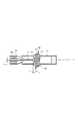
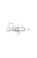
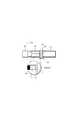
- FIG. 1is a longitudinal sectional view schematically showing an aerosol inhaler according to an embodiment of the present invention. It is the figure which showed the specific example of the liquid tank of FIG. It is the cross-sectional view which expanded and showed the heater of FIG. It is the figure which showed the heater of FIG. 1 with the electric power feeding circuit. It is the schematic which showed a part of aerosol inhaler before aerosol generation. It is the schematic which showed a part of aerosol suction device of the state which aerosol generate
- an aerosol inhaler 10 of one embodimentincludes a cylindrical outer tube 12 having both ends opened, and a mouthpiece 14 detachably connected to the base end of the outer tube 12.
- the outer tube 12 and the mouthpiece 14are each formed from a heat-resistant synthetic resin.
- the outer tube 12includes a lid 16 at the tip, and the lid 16 can be detached from the outer tube 12.
- a power unit 18 as a power source, a liquid tank 20 as a solution supply source, and an inner tube 22are accommodated.
- the power supply unit 18, the liquid tank 20, and the inner tube 22are sequentially arranged on the axis of the outer tube 12 from the lid 16 side.
- the inner tube 22communicates with the mouthpiece 14.
- the power supply unit 18 and the liquid tank 20can be replaced, and the replacement of the power supply unit 18 and the liquid tank 20 is performed by removing the lid 16 from the outer tube 12.
- the power supply unit 18includes a battery holder 24 and one commercially available battery held by the battery holder 24, for example, an AA battery 26. This battery 26 has a nominal voltage of 1.5 V and is arranged on the axis of the outer tube 12.
- the liquid tank 20is shown more specifically in FIG.
- the liquid tank 20includes a cylindrical tank casing 28.
- a plurality of ribsare formed on the outer peripheral surface of the tank casing 28. These ribs are arranged at intervals in the circumferential direction of the tank casing 28, and extend in the axial direction of the tank casing 28 except for the end of the tank casing 28 on the battery unit 18 side.
- the ribs described aboveform a plurality of axial passages 27 (see FIG. 1) between the outer surface of the tank casing 28 and the inner surface of the outer tube 12, while the end of the tank casing 28 and the inner surface of the outer tube 12 are connected to each other.
- An annular chamber 29(see FIG. 1) is secured in between. The annular chamber 29 is connected to the axial passage 27.
- a tube coil 30is accommodated in the tank casing 28.
- the tube coil 30extends in the axial direction of the outer tube 12 and has both ends opened.
- An introduction conduit 32extends from one end of the tube coil 30 to the outer surface of the tank casing 28, and the introduction conduit 32 opens at the outer surface of the outer casing 28 and is connected to the annular chamber 29 described above.
- a check valve 34is disposed in the introduction pipe line 32, and the check valve 34 opens only toward one end of the tube coil 30.
- a delivery line 36extends from the other end of the tube coil 30, and this delivery line 36 is connected to a capillary tube 40 via a joint 38.
- the capillary tube 40projects from the tank casing 28 into the inner tube 22 described above, and is positioned on the axis of the inner tube 22.
- the protruding end of the capillary tube 40forms a discharge end 42, and the discharge end 42 opens toward the mouthpiece 14.
- a check valve 44is also arranged in the delivery line 36, and the check valve 44 opens only toward the capillary tube 40.
- the interior flow path (introduction conduit 32, tube coil 30 and delivery conduit 36) of the liquid tank 22 and the capillary tube 40are filled with the solution to be aerosolized, and the solution reaches the discharge end 42 of the capillary tube 40.
- the solutioncan contain, for example, propylene glycol, glycerin and the like.
- the inner tube 22extends from the liquid tank 20 toward the mouthpiece 14 and is connected to the absorption sleeve 48.
- the absorption sleeve 48is positioned coaxially with the inner tube 22 and has the same inner diameter as the content of the inner tube 22.
- the thickness of the outer tube 12 surrounding the inner tube 22 and the absorption sleeve 48is thicker than the thickness of the outer tube 12 surrounding the power supply unit 18 and the liquid tank 20.
- the inner tube 22is made of, for example, stainless steel or ceramic.
- the absorption sleeve 48is formed by, for example, a paper tube or a hollow cylindrical paper filter capable of absorbing the solution described above. Such an absorption sleeve 48 has a volume sufficient to cover the required amount of solution absorption.
- a plurality of atmospheric ports 50are formed in the outer tube 12. These atmospheric ports 50 are, for example, adjacent to the liquid tank 20 and are arranged at intervals in the circumferential direction of the outer tube 12.
- the atmospheric port 50extends from the outer peripheral surface of the outer tube 12 through the inner tube 22.
- the atmospheric port 50provides an atmospheric opening 52 opened on the outer peripheral surface of the outer tube 12, and is connected to the annular chamber 29 via the axial passage 27 described above.
- the atmosphere port 50 and the inner tube 22form a suction path that connects the atmosphere opening 52 and the mouthpiece 14. Further, the atmospheric port 50 maintains the inside of the annular chamber 29 at atmospheric pressure, and as a result, the solution in the liquid tank 20 is always in the state of receiving atmospheric pressure through the opening end of the introduction pipe line 32.
- the negative pressure in the inner tube 22is caused to discharge a solution from the discharge end 42 of the capillary tube 40 into the suction path, that is, the inner tube 22, and the discharge amount of the solution here is determined by the strength of the negative pressure.
- the solutionis supplied from the liquid tank 20 to the capillary tube 40 by the amount of the discharged solution.
- the solution in the liquid tank 20constantly receives atmospheric pressure, the solution in the internal flow path of the liquid tank 20 moves toward the capillary tube 40 as the solution is replenished.
- a cylindrical heater 56is disposed in the inner tube 22, and this heater 56 is positioned immediately downstream of the discharge end 42 of the capillary tube 40 in view of the flow of air generated in the suction path.
- the outer diameter D O of the heater 56is smaller than the inner diameter D IT of the inner tube 22 and The inner diameter DCT or the diameter of the capillary tube 40 is larger.
- the outer diameter D Osatisfies the following relationship.
- the heater 56penetrates the inner tube 22 in the diameter direction, and has an axis perpendicular to the axis of the inner tube 22. Both ends of the heater 56 are supported by the outer tube 12.
- the discharge end 42 of the capillary tube 40is the heater.
- the cross section of the discharge end 42can be completely projected onto the outer surface of the heater 56.
- the maximum diameter of the dropletsis determined by the inner diameter D CT of the capillary tube 40
- D MAXthe maximum droplet diameter
- D CTthe distance Z between the discharge end 42 and the heater 56 has the following relationship.
- Table 1shows that when the solution is propylene glycol (PG: density 1.036 g / mm 2 ), the inner diameter D CT of the capillary tube 42 and the suction amount of the air generated in the inner tube 22 The relationship between discharge amount, discharge volume, and diameter is shown.
- PGpropylene glycol
- the liquid tank 20 of FIG. 3has a structure that is different from the structure of the liquid tank already described. Specifically, the liquid tank 20 of FIG. 3 has an internal flow path 30 a that extends in a zigzag shape instead of the coil tube 30. This means that the coil tube 30 is not essential for the liquid tank 20.
- the heater 56includes, for example, a nichrome wire 58 as a resistance heating element, and a cylindrical sheath element 60 covering the nichrome wire 58.
- the nichrome wire 58penetrates the sheath element 60 three times in the axial direction of the sheath element 60 and has two ends protruding from both ends of the sheath element 60.
- the nichrome wire 58is connected in series to the battery 26 described above via a power supply circuit 63, and the power supply circuit 63 has a switch 64.
- the power feeding circuit 63 and the switch 64are not shown in FIG. 1, the power feeding circuit 63 and the switch 64 are disposed on the inner surface of the outer tube 12, and the outer tube 12 is a push button (not illustrated) that operates the switch 64 on the outer surface. Not).
- the sheath element 60is made of ceramic such as alumina or silicon nitride, and provides the outer surface of the heater 56. Further, as apparent from FIG. 4, for example, an annular groove 62 is formed on a part of the outer surface of the sheath element 60, and a ring-shaped heat-resistant net 64 as a wetness increasing element is held in the annular groove 62. Is preferred.
- the net 64faces the discharge end 42 of the capillary tube 40, and the interval Z described above is defined between the discharge end 42 and the net 64.
- the sheath element 60 described abovenot only protects the nichrome wire 58 but also thermally connects the nichrome wire 58 and the net 64. Specifically, when the battery 26 is in a usable state and a voltage of 1 to 1.5 V is applied to the nichrome wire 58, the sheath element 60 quickly transfers the heat generated by the nichrome wire 58 to the outer surface of the heater 56. And has a function of maintaining the heating temperature of the outer surface of the heater 56 within a temperature range required for atomization of the solution. That is, the nichrome 58 and the sheath element 60 provide an internal structure that maintains the heating temperature of the outer surface of the heater 56 within the temperature range, and thus the sheath element 60 has a predetermined thickness and volume.
- FIG. 5shows a state where the above-described switch 64 of the power feeding circuit 63 is turned on and the aerosol inhaler can be used.
- the heating temperature of the outer surface of the heater 56is quickly maintained within the required temperature range, and the relationship in the above equation (2) is satisfied, so that the solution in the capillary tube 40 is It does not atomize in response to the radiant heat from the heater 56. That is, no aerosol is generated.
- the aerosol inhalerwhen the aerosol inhaler is sucked through the mouthpiece 14 by the user from the state shown in FIG. 5, the solution is discharged from the discharge end 42 of the capillary tube 40 as described above.
- the discharge solution Lis supplied to the heater 56 as shown in FIGS.
- the outer surfaceis securely received.
- the above-described net 64is provided on the outer surface of the heater 56, the discharged solution is received by the net 64 and extends and spreads on the net 64.
- the discharge solution Lis immediately atomized by being heated by the heater 56, and thereby the aerosol is injected into the inner tube 22. X is generated. Therefore, the user can suck the aerosol X through the mouthpiece 14.
- the heater 56has the net 64
- the net 64increases the wettability of the heater 56 with respect to the discharge solution L. Therefore, the discharge solution L is atomized in a wide area, and rapid aerosol is generated. To achieve. Further, when the user stops the suction operation, the solution discharge from the discharge end 42 of the capillary tube 40 is immediately stopped. Since wider than the interval Z is at least capillary tube 40 the inner diameter D CT between the outer surface of the discharge end 42 as is apparent from the foregoing description heater 56, keeping the heating temperature of the outer surface of the heater 56 is in the temperature range described above As long as this is done, the solution in the discharge end 42 is not atomized by receiving radiant heat from the heater 56.
- the generation of aerosolis stopped simultaneously with the stop of the user's suction operation, and the solution in the capillary tube 40 is not wasted.
- the usercan reliably suck the aerosol every time the suction operation is performed, and the amount of the aerosol sucked by the user is determined by the strength of the user's suction operation and the period of the suction operation.
- the relationship of the above equation (2)is not satisfied, and the interval Z is larger than the maximum diameter D MAX of the solution droplets. If there is, the discharge solution L is not received by the outer surface of the heater 56 and falls to the inner surface of the inner tube 22 as shown in FIG. In this case, the discharge solution L is not atomized and the user cannot aspirate the aerosol.
- the relationship of the expressions (1) and (2)is satisfied, and the heating temperature of the outer surface of the heater 56 is not maintained in an appropriate temperature range.
- the atomization of the discharge solution Lthat is, the generation of aerosol cannot be performed or the waste of the solution cannot be avoided.
- the heating temperature of the outer surface of the heater 56is required to be within a temperature range of 180 to 280 ° C. Is done.
- the aerosol inhalerdoes not include a control circuit that controls the heat generation of the nichrome wire 58. Therefore, in order to maintain the heating temperature of the outer surface of the heater 56 in the above-described temperature range, the thickness (volume) of the sheath element 60 must be set appropriately.
- the moving speed of heat reaching the outer surface of the heater 56 from the nichrome wire 58 through the sheath element 60is delayed, while the area of the outer surface of the sheath element 60 is increased. Increases the amount of heat radiation from the sheath element 60. That is, it is considered that the heating temperature of the outer surface of the heater 56 decreases as the thickness of the sheath element 60 increases.
- the present inventorsprepared heaters 56 A to 56 G that differ only in the thickness of the sheath element 60.
- the thickness of the sheath element 60 in the heater 56 A ⁇ 56 Gis increased by a predetermined increment in the order of the heaters 56 A ⁇ 56 G.
- FIG. 10shows a heating test apparatus for the heater 56 X (X represents any of A to G).
- the heating test apparatusincludes a power supply circuit 66 that applies a voltage to the heater 56 X.
- the power supply circuit 66includes a DC power supply 68 that can change the applied voltage, a shunt resistor 70 (1 m ⁇ ), and a voltmeter 72. X is connected in series with the shut resistor 70.
- the heating test apparatusincludes a temperature sensor 74 that can measure the temperature of the outer surface of the heater 56 X , ie, its sheath element 60.
- the temperature sensor 74includes a K thermocouple.
- nichrome wire 58When the heater 56 X is connected to the power supply circuit 66 as shown in FIG. 10, a voltage is applied from the DC power supply 68 to the nichrome wire 58 of the heater 56 X, nichrome wire 58 generates heat. The heat generated by the nichrome wire 58 moves in the sheath element 60 and raises the temperature of the sheath element 60 while being released from the outer surface of the sheath element 60 to the surroundings.
- the heating temperature of the outer surface of the sheath element 60is determined by the difference between the amount of heat generated by the nichrome wire 58 and the amount of heat released from the sheath element 60, and the rate of temperature rise of the outer surface of the sheath element 60 is determined by the sheath element 60. It is determined by the moving speed of the heat transferred in 60.
- the DC power source 68applies a voltage to the nichrome wire 56 while sequentially changing the applied voltage to the nichrome wire 58 within the range of 0.8V to 1.6V.
- the temperature sensor 74measures the heating temperature of the outer surface of the sheath element 60 for each applied voltage of the nichrome wire 58. The measurement results are shown in FIG.
- the heater 56 Xheats the outer surface of the sheath element 60 to a higher temperature as the applied voltage to the nichrome wire 58 becomes higher.
- the heating temperature of the outer surface of only the heater 56 F sheath element 60can be maintained in the above-mentioned temperature range (180 to 280 ° C.).
- the heater 56 Fis used as the heater 56 of this embodiment, the aerosol inhalator 10 without requiring a control circuit for controlling the voltage applied to the nichrome wire 58, the heating temperature of the outer surface of the heater 56 Can be maintained in the temperature range described above.
- the control circuitis not required for the aerosol inhaler 10
- the load on the battery 26is reduced, and the aerosol inhaler 10 can be used for a long period of time.
- the use of the battery 26realizes miniaturization or slimming of the aerosol inhaler 10 and improves the convenience of the aerosol inhaler.
- the generated aerosolmay be aggregated on the inner surface of the inner tube 22 and the solution may adhere to the inner surface of the inner tube 22. It is done. Such attached solution may move toward the mouthpiece 14 and flow into the user's oral cavity in accordance with the user's suction operation.
- the absorption sleeve 48 formed of a paper tube or a paper filteris disposed between the inner tube 22 and the mouthpiece 14, even if the adhesion solution moves toward the mouthpiece 14, the adhesion solution is absorbed. It is reliably absorbed by the sleeve 48 and does not flow into the user's mouth.
- the present inventionis not limited to the aerosol inhaler 10 of the embodiment described above, and various modifications are possible.
- the resistance heating elementis not limited to the nichrome wire, and the cross section of the heater 56 is not limited to a circle but may be an ellipse or a polygon.
- the sheath element 60may be made of metal, and may have a rough outer surface 66 as shown in FIG. 12, for example, at least at the site for receiving the above-described discharge solution, instead of the above-described net 64.
- the rough outer surface 62is formed by a large number of narrow annular grooves that are spaced apart in the axial direction of the sheath element 60, and such annular grooves are formed when the discharge solution is received on the outer surface 66 of the sheath element 60. Like 64, it functions to extend and spread the discharged solution.
- both the sheath element 60 and the inner tube 22 of the heater 56are made of the same ceramic, it is desirable that the sheath element 60 and the inner tube 22 are formed as a single-piece product. The number of parts can be reduced.
Landscapes
- Health & Medical Sciences (AREA)
- Engineering & Computer Science (AREA)
- Life Sciences & Earth Sciences (AREA)
- Animal Behavior & Ethology (AREA)
- Anesthesiology (AREA)
- Biomedical Technology (AREA)
- Heart & Thoracic Surgery (AREA)
- Hematology (AREA)
- Veterinary Medicine (AREA)
- Public Health (AREA)
- General Health & Medical Sciences (AREA)
- Pulmonology (AREA)
- Bioinformatics & Cheminformatics (AREA)
- Emergency Medicine (AREA)
- Nozzles (AREA)
- Media Introduction/Drainage Providing Device (AREA)
- Sampling And Sample Adjustment (AREA)
- Medicinal Preparation (AREA)
Abstract
Description
本発明は、ユーザの吸引動作に伴ってエアロゾルを発生させ、このエアロゾルをユーザに提供するエアロゾル吸引器に関する。The present invention relates to an aerosol inhaler that generates an aerosol in accordance with a user's suction operation and provides the aerosol to the user.
この種のエアゾロル吸引器は例えば、以下の特許文献1~4にそれぞれ開示されている。
特許文献1に開示されたエアロゾル吸引器は、マウスピースを備えた吸引パイプと、この吸引パイプに内蔵され、エアロゾル化すべき溶液を蓄えた溶液供給源と、この溶液供給源から吸引パイプ内の分配位置に溶液を定量ずつ分配可能な分配装置と、分配位置に分配された溶液を加熱によって霧化させることで、吸引パイプ内にエアロゾルを発生させる電気ヒータとを含む。This type of azolol suction device is disclosed in, for example, the followingPatent Documents 1 to 4.
An aerosol inhaler disclosed inPatent Document 1 includes a suction pipe provided with a mouthpiece, a solution supply source built in the suction pipe and storing a solution to be aerosolized, and a distribution in the suction pipe from the solution supply source It includes a dispensing device capable of dispensing the solution at a certain amount to the position, and an electric heater that generates aerosol in the suction pipe by atomizing the solution dispensed to the dispensing position by heating.
特許文献1に開示されたエアロゾル吸引器は、マウスピースを備えた吸引パイプと、この吸引パイプに内蔵され、エアロゾル化すべき溶液を蓄えた溶液供給源と、この溶液供給源から吸引パイプ内の分配位置に溶液を定量ずつ分配可能な分配装置と、分配位置に分配された溶液を加熱によって霧化させることで、吸引パイプ内にエアロゾルを発生させる電気ヒータとを含む。This type of azolol suction device is disclosed in, for example, the following
An aerosol inhaler disclosed in
特許文献2に開示されたエアロゾル吸引器は、ポンプによって供給された液体をエアロゾル化するため、電気ヒータ及び高周波発生器を含む。
特許文献3に開示されたエアロゾル吸引器は、液体をエアロゾル化するためインクジェットユニットを含む。
特許文献4に開示されたエアロゾル吸引器は、毛細管現象を利用した液供給経路と、この液供給経路の出口に配置された電気ヒータとを含む。The aerosol inhaler disclosed in Patent Document 2 includes an electric heater and a high-frequency generator in order to aerosolize the liquid supplied by the pump.
The aerosol inhaler disclosed in Patent Document 3 includes an inkjet unit for aerosolizing a liquid.
The aerosol inhaler disclosed in Patent Document 4 includes a liquid supply path using capillary action and an electric heater disposed at the outlet of the liquid supply path.
特許文献1のエアロゾル吸引器は、ユーザがマウスピースを通じて吸引動作を行う前に分配装置の手動操作を要求するか、又は、吸引動作と同時に分配装置の自動操作を要求する。分配装置の存在はエアロゾル吸引器の大型化を招く大きな要因になるばかりでなく、分配装置の手動操作はユーザによるエアロゾルの簡便な吸引を阻害する。The aerosol inhaler ofPatent Document 1 requires a manual operation of the distribution device before the user performs an aspiration operation through the mouthpiece, or requests an automatic operation of the distribution device simultaneously with the aspiration operation. The presence of the dispensing device is not only a major factor that leads to an increase in the size of the aerosol inhaler, but also the manual operation of the dispensing device hinders easy aspiration of the aerosol by the user.
一方、分配装置の自動操作はユーザにエアロゾルの簡便な吸引を提供するが、この場合、分配装置はその構造が複雑化になるばかりでなく、自動操作のための電気エネルギを消費する。このため、分配装置及び電気ヒータのために大容量の電源が必要不可欠となり、エアロゾル吸引器の更なる大型化を招く。On the other hand, the automatic operation of the dispensing device provides the user with simple aspiration of the aerosol. In this case, the dispensing device not only complicates its structure, but also consumes electrical energy for automatic operation. For this reason, a large-capacity power source is indispensable for the distribution device and the electric heater, and the size of the aerosol inhaler is further increased.
更に、特許文献2,3のエアロゾル吸引器は、特許文献1のエアロゾル吸引器と同様に、その複雑な構造に起因して小型化が困難である。一方、特許文献4のエアロゾル吸引器は特許文献1~3のエアロゾル吸引器に比べて簡単な構造を有するものの、特許文献1~3のエアロゾル吸引器と同様に、電気ヒータに液を直接的に衝突させて液のエアロゾル化を達成するものでもないので、確実なエアロゾル化が保証されない。Furthermore, the aerosol inhalers of Patent Documents 2 and 3 are difficult to miniaturize due to their complicated structure, similar to the aerosol inhaler ofPatent Document 1. On the other hand, the aerosol inhaler of Patent Document 4 has a simpler structure than the aerosol inhalers ofPatent Documents 1 to 3, but like the aerosol inhaler ofPatent Documents 1 to 3, the liquid is directly applied to the electric heater. Since it does not collide to achieve aerosolization of the liquid, reliable aerosolization is not guaranteed.
本発明の目的は、ユーザがエアロゾルを簡便に吸引でき、且つ、液のエアロゾル化を確実に保証することできる小型のエアロゾル吸引器を提供することある。An object of the present invention is to provide a small-sized aerosol inhaler that allows a user to easily inhale an aerosol and reliably ensure that the liquid is aerosolized.
上述の目的は本発明のエアロゾル吸引器によって達成され、このエアロゾル吸引器は、
大気開放口とマウスピースとを接続し、前記大気開放口から前記マウスピースへ向かう空気の流れを許容する吸引経路と、
エアロゾルを発生させる溶液を供給する溶液供給装置であって、前記溶液を蓄えた溶液供給源と、
この溶液供給源に接続されている一方、前記吸引経路内にて前記マウスピースに向けて開口した吐出端を有し、前記溶液供給源から前記吐出端まで前記溶液を導き且つ前記吸引経路内に前記空気の流れが生起されたときに前記吐出端から前記溶液を吐出させるキャピラリ管と
を含む溶液供給装置と、
前記吐出端からの吐出溶液を受け止め、この受け止めた吐出溶液を加熱によって霧化させるヒータ装置であって、
電源と、
吐出端の直下流にて、前記空気の流れを許容しつつ前記吐出端との間に所定の距離を存して前記吐出端と対向して配置され、前記電源の電圧が印加されているときに発熱する電気的なヒータとを含むヒータ装置と
を具備する。The above objective is accomplished by an aerosol inhaler according to the present invention, which comprises:
A suction path that connects the air opening and the mouthpiece, and allows a flow of air from the air opening to the mouthpiece;
A solution supply device for supplying a solution for generating an aerosol, the solution supply source storing the solution;
While connected to this solution supply source, it has a discharge end that opens toward the mouthpiece in the suction path, guides the solution from the solution supply source to the discharge end, and enters the suction path A solution supply device including a capillary tube for discharging the solution from the discharge end when the air flow is generated;
A heater device that receives the discharged solution from the discharge end and atomizes the received discharged solution by heating,
Power supply,
When the voltage of the power source is applied just downstream of the discharge end and arranged to face the discharge end with a predetermined distance between the discharge end while allowing the air flow And a heater device including an electric heater that generates heat.
上述のエアロゾル吸引器によれば、ユーザがマウスピースを通じて吸引動作を行ったとき、キャピラリ管の吐出端から溶液が吐出される。この吐出溶液はヒータの外面に受け止められると同時にヒータからの熱を受けて全て霧化し、吸引経路内にエアロゾルを発生される。それ故、ユーザはマウスピースを通じてエアロゾルを吸引することができる。According to the aerosol inhaler described above, the solution is discharged from the discharge end of the capillary tube when the user performs a suction operation through the mouthpiece. This discharged solution is received on the outer surface of the heater and at the same time receives all the heat from the heater to be atomized, and aerosol is generated in the suction path. Therefore, the user can inhale the aerosol through the mouthpiece.
具体的には、前記ヒータは前記吸引経路の軸線と直交し且つ前記吸引経路を横断する方向に延びている。好ましくは、キャピラリ管は前記吸引経路の軸線上を延びている。Specifically, the heater extends in a direction perpendicular to the suction path axis and across the suction path. Preferably, the capillary tube extends on the axis of the suction path.
本発明のエアロゾル吸引器は、ユーザの吸引動作に連動してキャピラリ管の吐出端から溶液を吐出させると同時に、吐出溶液をヒータの外面に受け止めることができるそれ故、吐出溶液はその全量がヒータの外面上に霧化し、吸引経路内にエアロゾルを発生させる。よって、ユーザはエアロゾルを簡便且つ効果的に吸引することができる。
本発明のエアロゾル吸引器の詳細及び他の利点は添付図面及び後述の説明から明らかとなる。The aerosol inhaler of the present invention discharges the solution from the discharge end of the capillary tube in conjunction with the user's suction operation, and at the same time, can receive the discharged solution on the outer surface of the heater. Atomized on the outer surface of the gas to generate aerosol in the suction path. Therefore, the user can inhale the aerosol easily and effectively.
Details and other advantages of the aerosol inhaler of the present invention will become apparent from the accompanying drawings and the following description.
図1を参照すると、一実施例のエアロゾル吸引器10は両端が開口した円筒形状のアウタチューブ12と、このアウタチューブ12の基端に分離可能に接続されたマウスピース14とを含む。これらアウタチューブ12及びマウスピース14は耐熱性を有した合成樹脂からそれぞれ形成されている。アウタチューブ12はその先端にリッド16を備え、このリッド16はアウタチューブ12から取り外し可能である。Referring to FIG. 1, anaerosol inhaler 10 of one embodiment includes a cylindricalouter tube 12 having both ends opened, and amouthpiece 14 detachably connected to the base end of theouter tube 12. Theouter tube 12 and themouthpiece 14 are each formed from a heat-resistant synthetic resin. Theouter tube 12 includes alid 16 at the tip, and thelid 16 can be detached from theouter tube 12.
アウタチューブ12内には電源としての電源ユニット18、溶液供給源としての液タンク20及びインナチューブ22が収容されている。これら電源ユニット18、液タンク20及びインナチューブ22はアウタチューブ12の軸線上にリッド16側から順次配置されている。インナチューブ22はマウスピース14に連通している。In theouter tube 12, apower unit 18 as a power source, aliquid tank 20 as a solution supply source, and aninner tube 22 are accommodated. Thepower supply unit 18, theliquid tank 20, and theinner tube 22 are sequentially arranged on the axis of theouter tube 12 from thelid 16 side. Theinner tube 22 communicates with themouthpiece 14.
電源ユニット18及び液タンク20は交換可能であり、これら電源ユニット18及び液タンク20の交換はアウタチューブ12からリッド16が取り外されることによって実施される。
電源ユニット18は電池ホルダ24と、この電池ホルダ24に保持された1本の市販の電池、例えば単三電池26とを含む。この電池26は1.5Vの公称電圧を有し、アウタチューブ12の軸線上に配置されている。Thepower supply unit 18 and theliquid tank 20 can be replaced, and the replacement of thepower supply unit 18 and theliquid tank 20 is performed by removing thelid 16 from theouter tube 12.
Thepower supply unit 18 includes abattery holder 24 and one commercially available battery held by thebattery holder 24, for example, anAA battery 26. Thisbattery 26 has a nominal voltage of 1.5 V and is arranged on the axis of theouter tube 12.
電源ユニット18は電池ホルダ24と、この電池ホルダ24に保持された1本の市販の電池、例えば単三電池26とを含む。この電池26は1.5Vの公称電圧を有し、アウタチューブ12の軸線上に配置されている。The
The
液タンク20は図2により具体的に示されている。
液タンク20は円筒形状のタンクケーシング28を含む。このタンクケーシング28の外周面には複数のリブが形成されている。これらリブはタンクケーシング28の周方向に間隔を存して配置され、そして、電池ユニット18側のタンクケーシング28の端部を除きタンクケーシング28の軸方向に延びている。Theliquid tank 20 is shown more specifically in FIG.
Theliquid tank 20 includes acylindrical tank casing 28. A plurality of ribs are formed on the outer peripheral surface of thetank casing 28. These ribs are arranged at intervals in the circumferential direction of thetank casing 28, and extend in the axial direction of thetank casing 28 except for the end of thetank casing 28 on thebattery unit 18 side.
液タンク20は円筒形状のタンクケーシング28を含む。このタンクケーシング28の外周面には複数のリブが形成されている。これらリブはタンクケーシング28の周方向に間隔を存して配置され、そして、電池ユニット18側のタンクケーシング28の端部を除きタンクケーシング28の軸方向に延びている。The
The
上述したリブはタンクケーシング28の外面とアウタチューブ12の内面との間に複数の軸方向通路27(図1参照)を形成し、一方、タンクケーシング28の前記端部とアウタチューブ12の内面とに間に環状室29(図1参照)を確保する。この環状室29は軸方向通路27に接続されている。The ribs described above form a plurality of axial passages 27 (see FIG. 1) between the outer surface of thetank casing 28 and the inner surface of theouter tube 12, while the end of thetank casing 28 and the inner surface of theouter tube 12 are connected to each other. An annular chamber 29 (see FIG. 1) is secured in between. Theannular chamber 29 is connected to theaxial passage 27.
タンクケーシング28内にはチューブコイル30が収容されている。このチューブコイル30はアウタチューブ12の軸線方向に延び、開口された両端を有する。チューブコイル30の一端からはタンクケーシング28の外面まで導入管路32が延び、この導入管路32はアウタケーシング28の外面にて開口し、前述した環状室29に接続されている。更に、導入管路32には逆止弁34が配置され、この逆止弁34はチューブコイル30の一端に向けてのみ開く。Atube coil 30 is accommodated in thetank casing 28. Thetube coil 30 extends in the axial direction of theouter tube 12 and has both ends opened. Anintroduction conduit 32 extends from one end of thetube coil 30 to the outer surface of thetank casing 28, and theintroduction conduit 32 opens at the outer surface of theouter casing 28 and is connected to theannular chamber 29 described above. Further, acheck valve 34 is disposed in theintroduction pipe line 32, and thecheck valve 34 opens only toward one end of thetube coil 30.
一方、チューブコイル30の他端からは送出管路36が延び、この送出管路36はジョイント38を介してキャピラリ管40に接続されている。このキャピラリ管40はタンクケーシング28から前述したインナチューブ22内に突出し、インナチューブ22の軸線上に位置付けられている。キャピラリ管40の突出端は吐出端42を形成し、この吐出端42はマウスピース14に向けて開口している。更に、送出管路36にも逆止弁44が配置されており、この逆止弁44はキャピラリ管40に向けてのみ開く。On the other hand, adelivery line 36 extends from the other end of thetube coil 30, and thisdelivery line 36 is connected to acapillary tube 40 via a joint 38. Thecapillary tube 40 projects from thetank casing 28 into theinner tube 22 described above, and is positioned on the axis of theinner tube 22. The protruding end of thecapillary tube 40 forms adischarge end 42, and thedischarge end 42 opens toward themouthpiece 14. Further, acheck valve 44 is also arranged in thedelivery line 36, and thecheck valve 44 opens only toward thecapillary tube 40.
液タンク22の内部流路(導入管路32、チューブコイル30及び送出管路36)及びキャピラリ管40内はエアロゾル化すべき溶液で満たされ、溶液はキャピラリ管40の吐出端42に達している。ここで、溶液は例えばプロピレングリコールやグリセリン等を含むことができる。The interior flow path (introduction conduit 32,tube coil 30 and delivery conduit 36) of theliquid tank 22 and thecapillary tube 40 are filled with the solution to be aerosolized, and the solution reaches the discharge end 42 of thecapillary tube 40. Here, the solution can contain, for example, propylene glycol, glycerin and the like.
図1から明らかなようにインナチューブ22は液タンク20からマウスピース14に向けて延び、吸収スリーブ48に接続されている。この吸収スリーブ48はインナチューブ22と同軸上に位置付けられ、インナチューブ22の内容と同一の内径を有する。なお、インナチューブ22及び吸収スリーブ48を囲むアウタチューブ12の部位の厚さは電源ユニット18や液タンク20を囲むアウタチューブ12の部位の厚さよりも厚い。As is clear from FIG. 1, theinner tube 22 extends from theliquid tank 20 toward themouthpiece 14 and is connected to theabsorption sleeve 48. Theabsorption sleeve 48 is positioned coaxially with theinner tube 22 and has the same inner diameter as the content of theinner tube 22. The thickness of theouter tube 12 surrounding theinner tube 22 and theabsorption sleeve 48 is thicker than the thickness of theouter tube 12 surrounding thepower supply unit 18 and theliquid tank 20.
詳しくは、インナチューブ22は例えばステンレス鋼又はセラミックから形成されている。一方、吸収スリーブ48は例えば、前述した溶液を吸収可能な紙管や中空筒形状のペーパフィルタによって形成されている。このような吸収スリーブ48は要求される溶液の吸収量を十分にカバーするだけの容積を有する。Specifically, theinner tube 22 is made of, for example, stainless steel or ceramic. On the other hand, theabsorption sleeve 48 is formed by, for example, a paper tube or a hollow cylindrical paper filter capable of absorbing the solution described above. Such anabsorption sleeve 48 has a volume sufficient to cover the required amount of solution absorption.
一方、図1に示されているように、アウタチューブ12には複数の大気ポート50が形成されている。これら大気ポート50は例えば液タンク20に隣接し、アウタチューブ12の周方向に間隔を存して配置されている。大気ポート50はアウタチューブ12の外周面からインナチューブ22を貫通して延びている。大気ポート50はアウタチューブ12の外周面に開口した大気開放口52を提供する一方、前述した軸方向通路27を経て環状室29に接続されている。On the other hand, as shown in FIG. 1, a plurality ofatmospheric ports 50 are formed in theouter tube 12. Theseatmospheric ports 50 are, for example, adjacent to theliquid tank 20 and are arranged at intervals in the circumferential direction of theouter tube 12. Theatmospheric port 50 extends from the outer peripheral surface of theouter tube 12 through theinner tube 22. Theatmospheric port 50 provides anatmospheric opening 52 opened on the outer peripheral surface of theouter tube 12, and is connected to theannular chamber 29 via theaxial passage 27 described above.
それ故、大気ポート50及びインナチューブ22は大気開放口52とマウスピース14とを接続する吸引経路を形成する。また、大気ポート50は環状室29内を大気圧に維持し、この結果、液タンク20内の溶液は導入管路32の開口端を通じて大気圧を常時受ける状態にある。Therefore, theatmosphere port 50 and theinner tube 22 form a suction path that connects theatmosphere opening 52 and themouthpiece 14. Further, theatmospheric port 50 maintains the inside of theannular chamber 29 at atmospheric pressure, and as a result, the solution in theliquid tank 20 is always in the state of receiving atmospheric pressure through the opening end of theintroduction pipe line 32.
今、ユーザがマウスピース14を通じてインナチューブ22内の空気を吸引したとき、インナチューブ22内の圧力は負圧になり、インナチューブ22内に大気ポート50を通じて外気が導入される。このような外気の導入は、前述した吸引経路内にマウスピース14に向かう空気の流れを発生させる。Now, when the user sucks the air in theinner tube 22 through themouthpiece 14, the pressure in theinner tube 22 becomes negative, and the outside air is introduced into theinner tube 22 through theatmospheric port 50. Such introduction of outside air generates a flow of air toward themouthpiece 14 in the above-described suction path.
インナチューブ22内の負圧はキャピラリ管40の吐出端42から吸引経路即ち、インナチューブ22内に溶液を吐出させ、ここでの溶液の吐出量は負圧の強さによって決定される。一方、吐出された溶液の分だけキャピラリ管40には液タンク20から溶液が補給される。前述したように液タンク20内の溶液は大気圧を常時受けているので、溶液の補給に伴い、液タンク20の内部流路内の溶液は、キャピラリ管40に向けて移動する。The negative pressure in theinner tube 22 is caused to discharge a solution from the discharge end 42 of thecapillary tube 40 into the suction path, that is, theinner tube 22, and the discharge amount of the solution here is determined by the strength of the negative pressure. On the other hand, the solution is supplied from theliquid tank 20 to thecapillary tube 40 by the amount of the discharged solution. As described above, since the solution in theliquid tank 20 constantly receives atmospheric pressure, the solution in the internal flow path of theliquid tank 20 moves toward thecapillary tube 40 as the solution is replenished.
インナチューブ22には円筒形状のヒータ56が配置されており、このヒータ56は吸引経路内に発生される空気の流れでみて、キャピラリ管40の吐出端42の直下流に位置付けられている。
図3に示されるように、インナチューブ22の内径及びキャピラリ管40の内径がそれぞれDIT,DCTで示されるとき、ヒータ56の外径DOはインナチューブ22の内径DITよりも小さく且つキャピラリ管40の内径DCT又は直径よりも大である。Acylindrical heater 56 is disposed in theinner tube 22, and thisheater 56 is positioned immediately downstream of the discharge end 42 of thecapillary tube 40 in view of the flow of air generated in the suction path.
As shown in FIG. 3, when the inner diameter of theinner tube 22 and the inner diameter of thecapillary tube 40 are respectively indicated by DIT and DCT , the outer diameter DO of theheater 56 is smaller than the inner diameter DIT of theinner tube 22 and The inner diameterDCT or the diameter of thecapillary tube 40 is larger.
図3に示されるように、インナチューブ22の内径及びキャピラリ管40の内径がそれぞれDIT,DCTで示されるとき、ヒータ56の外径DOはインナチューブ22の内径DITよりも小さく且つキャピラリ管40の内径DCT又は直径よりも大である。A
As shown in FIG. 3, when the inner diameter of the
即ち、外径DOは以下の関係を満たしている。
DIT>DO>DCT ……(1)
ヒータ56はインナチューブ22をその直径方向に貫通し、インナチューブ22の軸線と直交する軸線を有する。ヒータ56の両端はアウタチューブ12に支持されている。That is, the outer diameter DO satisfies the following relationship.
DIT > DO > DCT (1)
Theheater 56 penetrates theinner tube 22 in the diameter direction, and has an axis perpendicular to the axis of theinner tube 22. Both ends of theheater 56 are supported by theouter tube 12.
DIT>DO>DCT ……(1)
ヒータ56はインナチューブ22をその直径方向に貫通し、インナチューブ22の軸線と直交する軸線を有する。ヒータ56の両端はアウタチューブ12に支持されている。That is, the outer diameter DO satisfies the following relationship.
DIT > DO > DCT (1)
The
それ故、前述したようにキャピラリ管40がインナチューブ22の軸線上に位置付けられていることを考慮すれば、インナチューブ22の下流端からヒータ56をみたとき、キャピラリ管40の吐出端42はヒータ56によって隠される。換言すれば、吐出端42の横断面はヒータ56の外面上に完全に投影可能である。Therefore, considering that thecapillary tube 40 is positioned on the axis of theinner tube 22 as described above, when theheater 56 is viewed from the downstream end of theinner tube 22, the discharge end 42 of thecapillary tube 40 is the heater. Hidden by 56. In other words, the cross section of thedischarge end 42 can be completely projected onto the outer surface of theheater 56.
更に、前述したように吐出端42から溶液が吐出されるとき、吐出された溶液は吐出端42にて液滴を形成し、この液滴の最大径はキャピラリ管40の内径DCTによって決定される。ここで、液滴の最大径がDMAXで示されるとき、吐出端42とヒータ56との間の間隔Zは以下の関係を有する。
DMAX>Z>DCT ……(2)Further, when the solution is discharged from thedischarge end 42 as described above, is discharged solution droplets to form at thedischarge end 42, the maximum diameter of the droplets is determined by the inner diameter DCT of thecapillary tube 40 The Here, when the maximum droplet diameter is indicated by DMAX , the distance Z between thedischarge end 42 and theheater 56 has the following relationship.
DMAX >Z> DCT (2)
DMAX>Z>DCT ……(2)Further, when the solution is discharged from the
DMAX >Z> DCT (2)
それ故、吐出端42から溶液が吐出されたとき、吐出溶液はヒータ56の外面にて確実に受け止められる。
以下の表1は、溶液がプロピレングリコール(PG:密度1.036g/mm2)である場合、キャピラリ管42の内径DCT及びインナチューブ22内に発生される空気の吸引量に対し、液滴における吐出量、吐出体積及び径の関係を示す。Therefore, when the solution is discharged from thedischarge end 42, the discharged solution is reliably received on the outer surface of theheater 56.
Table 1 below shows that when the solution is propylene glycol (PG: density 1.036 g / mm2 ), the inner diameter DCT of thecapillary tube 42 and the suction amount of the air generated in theinner tube 22 The relationship between discharge amount, discharge volume, and diameter is shown.
以下の表1は、溶液がプロピレングリコール(PG:密度1.036g/mm2)である場合、キャピラリ管42の内径DCT及びインナチューブ22内に発生される空気の吸引量に対し、液滴における吐出量、吐出体積及び径の関係を示す。Therefore, when the solution is discharged from the
Table 1 below shows that when the solution is propylene glycol (PG: density 1.036 g / mm2 ), the inner diameter DCT of the

図3に示された液タンク20は、既に説明した液タンクの構造とは相違する構造を有する。具体的には、図3の液タンク20はコイルチューブ30に代えてジグザグ状に延びる内部流路30aを有する。このことは、コイルチューブ30が液タンク20にとって必須ではないことを意味する。3 has a structure that is different from the structure of the liquid tank already described. Specifically, theliquid tank 20 of FIG. 3 has aninternal flow path 30 a that extends in a zigzag shape instead of thecoil tube 30. This means that thecoil tube 30 is not essential for theliquid tank 20.
ヒータ56の構造に関し、以下に詳述する。
ヒータ56は例えば抵抗発熱要素としてのニクロム線58と、このニクロム線58を覆う円筒形状のシース要素60とを含む。本実施例の場合、図3から明らかなようにニクロム線58はシース要素60をこのシース要素60の軸線方向に3回貫通し、シース要素60の両端からそれぞれ突出した2つの端を有する。The structure of theheater 56 will be described in detail below.
Theheater 56 includes, for example, anichrome wire 58 as a resistance heating element, and acylindrical sheath element 60 covering thenichrome wire 58. In the case of this embodiment, as is apparent from FIG. 3, thenichrome wire 58 penetrates thesheath element 60 three times in the axial direction of thesheath element 60 and has two ends protruding from both ends of thesheath element 60.
ヒータ56は例えば抵抗発熱要素としてのニクロム線58と、このニクロム線58を覆う円筒形状のシース要素60とを含む。本実施例の場合、図3から明らかなようにニクロム線58はシース要素60をこのシース要素60の軸線方向に3回貫通し、シース要素60の両端からそれぞれ突出した2つの端を有する。The structure of the
The
図4に示されるようにニクロム線58は前述した電池26に給電回路63を介して直列に接続され、この給電回路63はスイッチ64を有する。図1に給電回路63及びスイッチ64は示されていないが、給電回路63及びスイッチ64はアウタチューブ12の内面に配置され、そして、アウタチューブ12はその外面にスイッチ64を操作するプッシュボタン(図示しない)を有する。As shown in FIG. 4, thenichrome wire 58 is connected in series to thebattery 26 described above via apower supply circuit 63, and thepower supply circuit 63 has aswitch 64. Although thepower feeding circuit 63 and theswitch 64 are not shown in FIG. 1, thepower feeding circuit 63 and theswitch 64 are disposed on the inner surface of theouter tube 12, and theouter tube 12 is a push button (not illustrated) that operates theswitch 64 on the outer surface. Not).
シース要素60はアルミナや窒化ケイ素等のセラミックから形成され、ヒータ56の外面を提供する。更に、図4から明らかなようにシース要素60の外面にはその一部に例えば環状溝62が形成され、この環状溝62に濡れ増加要素としてのリング状の耐熱性ネット64が保持されているのが好ましい。このネット64はキャピラリ管40の吐出端42と正対し、前述した間隔Zは吐出端42とネット64との間にて規定される。Thesheath element 60 is made of ceramic such as alumina or silicon nitride, and provides the outer surface of theheater 56. Further, as apparent from FIG. 4, for example, anannular groove 62 is formed on a part of the outer surface of thesheath element 60, and a ring-shaped heat-resistant net 64 as a wetness increasing element is held in theannular groove 62. Is preferred. The net 64 faces the discharge end 42 of thecapillary tube 40, and the interval Z described above is defined between thedischarge end 42 and the net 64.
上述したシース要素60はニクロム線58を保護するばかりでなく、ニクロム線58とネット64とを熱的に接続する。詳しくは、電池26が使用可能な状態にあって、1~1.5Vの電圧をニクロム線58に印加するとき、シース要素60はニクロム線58が発生した熱をヒータ56の外面に速やかに伝達し、ヒータ56の外面の加熱温度を溶液の霧化に要求される温度範囲内に維持する機能を有する。即ち、ニクロム58及びシース要素60はヒータ56の外面の加熱温度を前記温度範囲に維持する内部構造を提供し、このため、シース要素60は所定の厚み及び容積を有する。Thesheath element 60 described above not only protects thenichrome wire 58 but also thermally connects thenichrome wire 58 and the net 64. Specifically, when thebattery 26 is in a usable state and a voltage of 1 to 1.5 V is applied to thenichrome wire 58, thesheath element 60 quickly transfers the heat generated by thenichrome wire 58 to the outer surface of theheater 56. And has a function of maintaining the heating temperature of the outer surface of theheater 56 within a temperature range required for atomization of the solution. That is, thenichrome 58 and thesheath element 60 provide an internal structure that maintains the heating temperature of the outer surface of theheater 56 within the temperature range, and thus thesheath element 60 has a predetermined thickness and volume.
次に、図5~図9を参照しながら一実施例に係るエアロゾル吸引器の動作原理を説明する。なお、図5~図9中、ヒータ56のネット64は省略されている。
図5は前述した給電回路63のスイッチ64がオン操作され、エアロゾル吸引器が使用可能な状態を示す。この状態にあるとき、ヒータ56の外面の加熱温度は要求される温度範囲内に速やかに維持され、且つ、前記(2)式の関係が満たされていることで、キャピラリ管40内の溶液がヒータ56からの輻射熱を受けて霧化することはない。即ち、エアロゾルは発生されない。Next, the operation principle of the aerosol inhaler according to one embodiment will be described with reference to FIGS. 5 to 9, the net 64 of theheater 56 is omitted.
FIG. 5 shows a state where the above-describedswitch 64 of thepower feeding circuit 63 is turned on and the aerosol inhaler can be used. In this state, the heating temperature of the outer surface of theheater 56 is quickly maintained within the required temperature range, and the relationship in the above equation (2) is satisfied, so that the solution in thecapillary tube 40 is It does not atomize in response to the radiant heat from theheater 56. That is, no aerosol is generated.
図5は前述した給電回路63のスイッチ64がオン操作され、エアロゾル吸引器が使用可能な状態を示す。この状態にあるとき、ヒータ56の外面の加熱温度は要求される温度範囲内に速やかに維持され、且つ、前記(2)式の関係が満たされていることで、キャピラリ管40内の溶液がヒータ56からの輻射熱を受けて霧化することはない。即ち、エアロゾルは発生されない。Next, the operation principle of the aerosol inhaler according to one embodiment will be described with reference to FIGS. 5 to 9, the net 64 of the
FIG. 5 shows a state where the above-described
しかしながら、図5に示す状態からエアロゾル吸引器がユーザによりマウスピース14を通じて吸引されたとき、前述したようにキャピラリ管40の吐出端42から溶液が吐出される。ここで、キャピラリ管40とヒータ56との間には前述の(1),(2)式の関係が達成されているので、図6及び図7に示されるように吐出溶液Lはヒータ56の外面に確実に受け止められる。ここで、ヒータ56の外面に前述したネット64が備えられている場合、吐出溶液はネット64に受け止めらさ、このネット64上にて延び広がる。However, when the aerosol inhaler is sucked through themouthpiece 14 by the user from the state shown in FIG. 5, the solution is discharged from the discharge end 42 of thecapillary tube 40 as described above. Here, since the relationship of the above-described equations (1) and (2) is achieved between thecapillary tube 40 and theheater 56, the discharge solution L is supplied to theheater 56 as shown in FIGS. The outer surface is securely received. Here, when the above-describednet 64 is provided on the outer surface of theheater 56, the discharged solution is received by the net 64 and extends and spreads on the net 64.
このとき、ヒータ56の外面の加熱温度は前述の温度範囲内に既に維持されていることから、吐出溶液Lはヒータ56により加熱されることで直ちに霧化し、これにより、インナチューブ22内にエアロゾルXが発生する。それ故、ユーザはマウスピース14を通じてエアロゾルXを吸引することができる。At this time, since the heating temperature of the outer surface of theheater 56 is already maintained within the above-described temperature range, the discharge solution L is immediately atomized by being heated by theheater 56, and thereby the aerosol is injected into theinner tube 22. X is generated. Therefore, the user can suck the aerosol X through themouthpiece 14.
また、ヒータ56がネット64を有している場合、ネット64は、吐出溶液Lに対するヒータ56の濡れ性を増加させることから、吐出溶液Lを広い領域にて霧化させ、速やかなエアロゾルの発生を達成する。
更に、ユーザが吸引動作を停止すれば、キャピラリ管40の吐出端42からの溶液の吐出は直ちに停止される。前述の説明から明らかなように吐出端42とヒータ56の外面との間の間隔Zは少なくともキャピラリ管40の内径DCTよりも広いので、ヒータ56の外面の加熱温度が前述の温度範囲に維持されている限り、吐出端42内の溶液がヒータ56からの輻射熱を受けて霧化することもない。Further, when theheater 56 has the net 64, the net 64 increases the wettability of theheater 56 with respect to the discharge solution L. Therefore, the discharge solution L is atomized in a wide area, and rapid aerosol is generated. To achieve.
Further, when the user stops the suction operation, the solution discharge from the discharge end 42 of thecapillary tube 40 is immediately stopped. Since wider than the interval Z is at leastcapillary tube 40 the inner diameter DCT between the outer surface of thedischarge end 42 as is apparent from the foregoingdescription heater 56, keeping the heating temperature of the outer surface of theheater 56 is in the temperature range described above As long as this is done, the solution in thedischarge end 42 is not atomized by receiving radiant heat from theheater 56.
更に、ユーザが吸引動作を停止すれば、キャピラリ管40の吐出端42からの溶液の吐出は直ちに停止される。前述の説明から明らかなように吐出端42とヒータ56の外面との間の間隔Zは少なくともキャピラリ管40の内径DCTよりも広いので、ヒータ56の外面の加熱温度が前述の温度範囲に維持されている限り、吐出端42内の溶液がヒータ56からの輻射熱を受けて霧化することもない。Further, when the
Further, when the user stops the suction operation, the solution discharge from the discharge end 42 of the
それ故、ユーザの吸引動作の停止と同時に、エアロゾルの発生も停止され、キャピラリ管40内の溶液が浪費されることもない。
この結果、ユーザは吸引動作を行う毎にエアロゾルを確実に吸引することができ、ユーザが吸引するエアロゾルの吸引量は、ユーザの吸引動作の強さ及び吸引動作の期間によって決定される。Therefore, the generation of aerosol is stopped simultaneously with the stop of the user's suction operation, and the solution in thecapillary tube 40 is not wasted.
As a result, the user can reliably suck the aerosol every time the suction operation is performed, and the amount of the aerosol sucked by the user is determined by the strength of the user's suction operation and the period of the suction operation.
この結果、ユーザは吸引動作を行う毎にエアロゾルを確実に吸引することができ、ユーザが吸引するエアロゾルの吸引量は、ユーザの吸引動作の強さ及び吸引動作の期間によって決定される。Therefore, the generation of aerosol is stopped simultaneously with the stop of the user's suction operation, and the solution in the
As a result, the user can reliably suck the aerosol every time the suction operation is performed, and the amount of the aerosol sucked by the user is determined by the strength of the user's suction operation and the period of the suction operation.
一方、ヒータ56の外面の加熱温度が前述の温度範囲に維持されているとしても、前述の(2)式の関係が満たされず、間隔Zが溶液の液滴の最大径DMAXよりも大であれば、図8に示されるように吐出溶液Lはヒータ56の外面に受け止められず、インナチューブ22の内面に落下する。この場合、吐出溶液Lは霧化されず、ユーザはエアロゾルを吸引することができない。On the other hand, even if the heating temperature of the outer surface of theheater 56 is maintained within the above temperature range, the relationship of the above equation (2) is not satisfied, and the interval Z is larger than the maximum diameter DMAX of the solution droplets. If there is, the discharge solution L is not received by the outer surface of theheater 56 and falls to the inner surface of theinner tube 22 as shown in FIG. In this case, the discharge solution L is not atomized and the user cannot aspirate the aerosol.
逆に、間隔Zがキャピラリ管40の内径DCTよりも狭ければ、図9に示されるようにキャピラリ管40内の溶液がヒータ56からの輻射熱によって霧化される虞がある。この場合、前述したようにユーザの吸引動作とは無関係にエアロゾルXが発生し、液タンク20内の溶液が浪費される。Conversely, if the interval Z is narrow than the inner diameter DCT of thecapillary tube 40, there is a possibility that a solution of thecapillary tube 40 as shown in FIG. 9 is atomized by radiation heat from theheater 56. In this case, as described above, aerosol X is generated regardless of the user's suction operation, and the solution in theliquid tank 20 is wasted.
それ故、本実施例のエアロゾル吸引器とって、(1),(2)式の関係が満たされていることは勿論、ヒータ56の外面の加熱温度が適切な温度範囲に維持されていなければ、吐出溶液Lの霧化、即ち、エアロゾルの発生が不能になるか、又は、溶液の浪費を避けることができない。Therefore, in the aerosol inhaler of the present embodiment, the relationship of the expressions (1) and (2) is satisfied, and the heating temperature of the outer surface of theheater 56 is not maintained in an appropriate temperature range. The atomization of the discharge solution L, that is, the generation of aerosol cannot be performed or the waste of the solution cannot be avoided.
具体的には、(1),(2)式の関係が満たされ、且つ、溶液がプロピレングリコールである場合、ヒータ56の外面の加熱温度には180~280℃の温度範囲内の温度が要求される。Specifically, when the relationship of the expressions (1) and (2) is satisfied and the solution is propylene glycol, the heating temperature of the outer surface of theheater 56 is required to be within a temperature range of 180 to 280 ° C. Is done.
本実施例の場合、エアロゾル吸引器はニクロム線58の発熱を制御する制御回路を含んでいない。それ故、ヒータ56の外面の加熱温度が前述の温度範囲に維持されるためには、シース要素60の厚み(容積)が適切に設定されていなければならない。In the case of this embodiment, the aerosol inhaler does not include a control circuit that controls the heat generation of thenichrome wire 58. Therefore, in order to maintain the heating temperature of the outer surface of theheater 56 in the above-described temperature range, the thickness (volume) of thesheath element 60 must be set appropriately.
ここで、シース要素60の厚みが増加すればする程、ニクロム線58からシース要素60を経てヒータ56の外面に到達する熱の移動速度に遅れが生じ、一方、シース要素60における外表面の面積が増加することから、シース要素60からの熱放射量の増加を招く。即ち、シース要素60の厚みが増加すればする程、ヒータ56の外面の加熱温度が低下すると考えられる。Here, as the thickness of thesheath element 60 increases, the moving speed of heat reaching the outer surface of theheater 56 from thenichrome wire 58 through thesheath element 60 is delayed, while the area of the outer surface of thesheath element 60 is increased. Increases the amount of heat radiation from thesheath element 60. That is, it is considered that the heating temperature of the outer surface of theheater 56 decreases as the thickness of thesheath element 60 increases.
このようなヒータ56の外面の加熱温度の低下を確認するため、本発明者等はシース要素60の厚みのみが異なるヒータ56A~56Gをそれぞれ準備した。ここで、ヒータ56A~56Gにおけるシース要素60の厚みはヒータ56A~56Gの順に一定の増分ずつ増加されている。In order to confirm such a decrease in the heating temperature of the outer surface of theheater 56, the present inventors preparedheaters 56A to 56G that differ only in the thickness of thesheath element 60. The thickness of thesheath element 60 in the heater56 A ~ 56G is increased by a predetermined increment in the order of the heaters56 A ~56G.
図10はヒータ56X(XはA~Gの何れを示す)のための加熱試験装置を示す。
この加熱試験装置はヒータ56Xに電圧を印加する給電回路66を含み、この給電回路66は、印加電圧を可変可能な直流電源68、シャント抵抗70(1mΩ)及び電圧計72を含み、ヒータ56Xはシャット抵抗70と直列に接続されている。FIG. 10 shows a heating test apparatus for the heater 56X (X represents any of A to G).
The heating test apparatus includes apower supply circuit 66 that applies a voltage to theheater 56X. Thepower supply circuit 66 includes aDC power supply 68 that can change the applied voltage, a shunt resistor 70 (1 mΩ), and avoltmeter 72.X is connected in series with theshut resistor 70.
この加熱試験装置はヒータ56Xに電圧を印加する給電回路66を含み、この給電回路66は、印加電圧を可変可能な直流電源68、シャント抵抗70(1mΩ)及び電圧計72を含み、ヒータ56Xはシャット抵抗70と直列に接続されている。FIG. 10 shows a heating test apparatus for the heater 56X (X represents any of A to G).
The heating test apparatus includes a
更に、加熱試験装置は温度センサ74を含み、この温度センサ74はヒータ56X、即ち、そのシース要素60の外面の温度を測定可能である。具体的には、温度センサ74はK熱電対を含む。Further, the heating test apparatus includes atemperature sensor 74 that can measure the temperature of the outer surface of theheater 56X , ie, itssheath element 60. Specifically, thetemperature sensor 74 includes a K thermocouple.
図10に示されるように給電回路66にヒータ56Xが接続されたとき、ヒータ56Xのニクロム線58に直流電源68から電圧が印加され、ニクロム線58は発熱する。ニクロム線58が発生した熱はシース要素60内を移動し、シース要素60の温度を上昇させる一方、シース要素60の外面から周囲に放出される。When theheater 56X is connected to thepower supply circuit 66 as shown in FIG. 10, a voltage is applied from theDC power supply 68 to thenichrome wire 58 of theheater 56X,nichrome wire 58 generates heat. The heat generated by thenichrome wire 58 moves in thesheath element 60 and raises the temperature of thesheath element 60 while being released from the outer surface of thesheath element 60 to the surroundings.
この結果、シース要素60の外面の加熱温度は、ニクロム線58の発熱量とシース要素60からの放出熱量との間の差によって決定され、また、シース要素60の外面の温度上昇速度はシース要素60内を伝達される熱の移動速度によって決定される。As a result, the heating temperature of the outer surface of thesheath element 60 is determined by the difference between the amount of heat generated by thenichrome wire 58 and the amount of heat released from thesheath element 60, and the rate of temperature rise of the outer surface of thesheath element 60 is determined by thesheath element 60. It is determined by the moving speed of the heat transferred in 60.
ヒータ56Xの加熱試験を実施するにあたり、直流電源68は、ニクロム線58への印加電圧を0.8Vから1.6Vの範囲内にて順次変更しながらニクロム線56に電圧を印加し、一方、温度センサ74はニクロム線58の印加された電圧毎にシース要素60の外面の加熱温度を測定する。測定結果は図11に示されている。In performing the heating test of theheater 56X , theDC power source 68 applies a voltage to thenichrome wire 56 while sequentially changing the applied voltage to thenichrome wire 58 within the range of 0.8V to 1.6V. Thetemperature sensor 74 measures the heating temperature of the outer surface of thesheath element 60 for each applied voltage of thenichrome wire 58. The measurement results are shown in FIG.
図11から明らかなようにヒータ56Xは、ニクロム線58に対する印加電圧が高くなればなる程、シース要素60の外面は高い温度に加熱される。
しかしながら、単三電池26の通常の使用状態にて、単三電池26の印加電圧が1.0V~1.5Vであることを考慮すれば、ヒータ56Fのみがシース要素60の外面の加熱温度を前述した温度範囲(180~280℃)に維持することができる。As apparent from FIG. 11, theheater 56X heats the outer surface of thesheath element 60 to a higher temperature as the applied voltage to thenichrome wire 58 becomes higher.
However, in normal use of theAA battery 26, considering that the applied voltage ofAA batteries 26 is 1.0 V ~ 1.5V, the heating temperature of the outer surface of only theheater 56Fsheath element 60 Can be maintained in the above-mentioned temperature range (180 to 280 ° C.).
しかしながら、単三電池26の通常の使用状態にて、単三電池26の印加電圧が1.0V~1.5Vであることを考慮すれば、ヒータ56Fのみがシース要素60の外面の加熱温度を前述した温度範囲(180~280℃)に維持することができる。As apparent from FIG. 11, the
However, in normal use of the
このことは、本実施例のヒータ56としてヒータ56Fが使用されば、エアロゾル吸引器10はニクロム線58への印加電圧を制御する制御回路を必要とすることなく、ヒータ56の外面の加熱温度を前述した温度範囲に維持可能であることを意味する。This means that, if theheater 56F is used as theheater 56 of this embodiment, theaerosol inhalator 10 without requiring a control circuit for controlling the voltage applied to thenichrome wire 58, the heating temperature of the outer surface of theheater 56 Can be maintained in the temperature range described above.
また、このようにエアロゾル吸引器10に制御回路が不要であれば、電池26の負荷が軽減され、エアロゾル吸引器10の長期に亘る使用が可能となる。更に、電池26の使用は、エアロゾル吸引器10の小型化又はスリム化を実現し、エアロゾル吸引器の利便性を向上させる。In addition, if the control circuit is not required for theaerosol inhaler 10, the load on thebattery 26 is reduced, and theaerosol inhaler 10 can be used for a long period of time. Furthermore, the use of thebattery 26 realizes miniaturization or slimming of theaerosol inhaler 10 and improves the convenience of the aerosol inhaler.
一方、電池26の電圧低下に起因してヒータ56の外面の加熱温度が前記温度範囲よりも低い状況下にて、ユーザが吸引動作を行うと、キャピラリ管40から吐出された溶液の霧化が不十分となり、吐出溶液の一部がインナチューブ22の内面に付着する虞がある。On the other hand, when the user performs a suction operation in a situation where the heating temperature of the outer surface of theheater 56 is lower than the temperature range due to the voltage drop of thebattery 26, the solution discharged from thecapillary tube 40 is atomized. There is a risk that a part of the discharged solution may adhere to the inner surface of theinner tube 22.
更には、ヒータ56の外面の加熱温度が前記温度範囲内に維持されていても、発生されたエアロゾルがインナチューブ22の内面にて凝集し、インナチューブ22の内面に溶液が付着することも考えられる。
このような付着溶液はユーザの吸引動作に伴い、マウスピース14に向けて移動し、ユーザの口腔内に流入する恐れがある。Furthermore, even if the heating temperature of the outer surface of theheater 56 is maintained within the above temperature range, the generated aerosol may be aggregated on the inner surface of theinner tube 22 and the solution may adhere to the inner surface of theinner tube 22. It is done.
Such attached solution may move toward themouthpiece 14 and flow into the user's oral cavity in accordance with the user's suction operation.
このような付着溶液はユーザの吸引動作に伴い、マウスピース14に向けて移動し、ユーザの口腔内に流入する恐れがある。Furthermore, even if the heating temperature of the outer surface of the
Such attached solution may move toward the
しかしながら、インナチューブ22とマウスピース14との間に紙管やペーパフィルタから形成された吸収スリーブ48が配置されているので、付着溶液がマウスピース14に向けて移動しても、付着溶液は吸収スリーブ48に確実に吸収され、ユーザの口腔内に溶液を流入することはない。However, since theabsorption sleeve 48 formed of a paper tube or a paper filter is disposed between theinner tube 22 and themouthpiece 14, even if the adhesion solution moves toward themouthpiece 14, the adhesion solution is absorbed. It is reliably absorbed by thesleeve 48 and does not flow into the user's mouth.
本発明は上述した一実施例のエアロゾル吸引器10に制約されるものではなく、種々の変形が可能である。
例えば、ヒータ56に関し、抵抗発熱要素はニクロム線に限られるものではなし、ヒータ56の横断面は円形に限らず、楕円又は多角形等の形状であってもよい。The present invention is not limited to theaerosol inhaler 10 of the embodiment described above, and various modifications are possible.
For example, regarding theheater 56, the resistance heating element is not limited to the nichrome wire, and the cross section of theheater 56 is not limited to a circle but may be an ellipse or a polygon.
例えば、ヒータ56に関し、抵抗発熱要素はニクロム線に限られるものではなし、ヒータ56の横断面は円形に限らず、楕円又は多角形等の形状であってもよい。The present invention is not limited to the
For example, regarding the
シース要素60は金属から形成されていてもよいし、前述したネット64に代えて、少なくとも前述した吐出溶液を受け止める部位に例えば図12に示されるような粗い外面66を有することができる。例えば、粗い外面62はシース要素60の軸線方向に間隔を存して並ぶ多数の狭い環状溝によって形成され、このような環状溝はシース要素60の外面66に吐出溶液が受け止められたとき、ネット64と同様に吐出溶液を延び広げる働きをなす。Thesheath element 60 may be made of metal, and may have a roughouter surface 66 as shown in FIG. 12, for example, at least at the site for receiving the above-described discharge solution, instead of the above-describednet 64. For example, the roughouter surface 62 is formed by a large number of narrow annular grooves that are spaced apart in the axial direction of thesheath element 60, and such annular grooves are formed when the discharge solution is received on theouter surface 66 of thesheath element 60. Like 64, it functions to extend and spread the discharged solution.
更には、ヒータ56のシース要素60及びインナチューブ22が共に同一のセラミックからなる場合、これらシース要素60及びインナチューブ22は一体成形品として形成されているのが望ましく、これにより、エアロゾル吸引器の部品点数を削減することができる。Furthermore, when both thesheath element 60 and theinner tube 22 of theheater 56 are made of the same ceramic, it is desirable that thesheath element 60 and theinner tube 22 are formed as a single-piece product. The number of parts can be reduced.
12 アウタチューブ
14 マウスピース
18 電源ユニット
20 液タンク
22 インナチューブ
26 電池
40 キャピラリ管
42 分配口
48 吸収スリーブ(紙管、ペーパフィルタ)
50 大気ポート
52 大気開放口
56 ヒータ
58 ニクロム線(抵抗発熱要素)
60 シース要素
64 ネット(濡れ増加要素)
12Outer tube 14Mouthpiece 18Power supply unit 20Liquid tank 22Inner tube 26Battery 40Capillary tube 42Distribution port 48 Absorbing sleeve (paper tube, paper filter)
50Air port 52 Air opening 56Heater 58 Nichrome wire (resistance heating element)
60sheath element 64 net (wetting increase element)
14 マウスピース
18 電源ユニット
20 液タンク
22 インナチューブ
26 電池
40 キャピラリ管
42 分配口
48 吸収スリーブ(紙管、ペーパフィルタ)
50 大気ポート
52 大気開放口
56 ヒータ
58 ニクロム線(抵抗発熱要素)
60 シース要素
64 ネット(濡れ増加要素)
12
50
60
Claims (12)
- 大気開放口とマウスピースとを接続し、前記大気開放口から前記マウスピースへ向かう空気の流れを許容する吸引経路と、
エアロゾルを発生させる溶液を供給する溶液供給装置であって、
前記溶液を蓄えた溶液供給源と、
前記溶液供給源に接続されている一方、前記吸引経路内にて前記マウスピースに向けて開口した吐出端を有し、前記溶液供給源から前記吐出端まで前記溶液を導き且つ前記吸引経路内に前記空気の流れが生起されたときに前記吐出端から前記溶液を吐出させるキャピラリ管と
を含む溶液供給装置と、
前記吐出端からの吐出溶液を受け止め、この受け止めた吐出溶液を加熱によって霧化させるヒータ装置であって、
電源と、
吐出端の直下流にて、前記空気の流れを許容しつつ前記吐出端との間に所定の距離を存して前記吐出端と対向して配置され、前記電源の電圧が印加されているときに発熱する電気的なヒータと
を含むヒータ装置と
を具備したことを特徴とするエアロゾル吸引器。A suction path that connects the air opening and the mouthpiece, and allows a flow of air from the air opening to the mouthpiece;
A solution supply device for supplying a solution for generating an aerosol,
A solution source storing the solution;
The solution supply source has a discharge end that opens toward the mouthpiece in the suction path, guides the solution from the solution supply source to the discharge end, and enters the suction path. A solution supply device including a capillary tube for discharging the solution from the discharge end when the air flow is generated;
A heater device that receives the discharged solution from the discharge end and atomizes the received discharged solution by heating,
Power supply,
When the voltage of the power source is applied just downstream of the discharge end and arranged to face the discharge end with a predetermined distance between the discharge end while allowing the air flow An aerosol inhaler comprising a heater device including an electric heater that generates heat. - 前記ヒータは前記吸引経路の軸線と直交し且つ前記吸引経路を横断する方向に延びていることを特徴する請求項1に記載のエアロゾル吸引器。The aerosol inhaler according to claim 1, wherein the heater extends in a direction orthogonal to the axis of the suction path and across the suction path.
- 前記キャピラリ管は前記吸引経路の軸線上を延びていることを特徴とする請求項1に記載のエアロゾル吸引器。The aerosol inhaler according to claim 1, wherein the capillary tube extends on an axis of the suction path.
- 前記距離は、前記吐出端に前記溶液の表面張力によって形成される最大の液滴の直径よりも短いことを特徴とする請求項1に記載のエアロゾル吸引器。2. The aerosol inhaler according to claim 1, wherein the distance is shorter than a diameter of a maximum droplet formed by a surface tension of the solution at the discharge end.
- 前記距離は、前記キャピラリ管の内径よりも長いことを特徴とする請求項4に記載のエアロゾル吸引器。The aerosol inhaler according to claim 4, wherein the distance is longer than an inner diameter of the capillary tube.
- 前記キャピラリ管の直径は、前記ヒータの直径よりも小さいことを特徴とする請求項4に記載のエアロゾル吸引器。The aerosol inhaler according to claim 4, wherein a diameter of the capillary tube is smaller than a diameter of the heater.
- 前記吐出端は、前記吸引経路内を前記マウスピース側からみたとき、前記ヒータによって隠れるべく位置付けられていることを特徴とする請求項1に記載のエアロゾル吸引器。The aerosol inhaler according to claim 1, wherein the discharge end is positioned to be hidden by the heater when the inside of the suction path is viewed from the mouthpiece side.
- 前記ヒータはその外面の少なくとも一部に非平滑領域を有し、この非平滑領域にて前記吐出溶液を受け止めることを特徴とする請求項1に記載のエアロゾル吸引器。The aerosol inhaler according to claim 1, wherein the heater has a non-smooth area on at least a part of its outer surface, and receives the discharged solution in the non-smooth area.
- 前記ヒータは、その外面の加熱温度を前記印加電圧及び前記外面からの熱放射のみにより、前記吐出溶液の霧化に要求される所定の温度範囲に維持する内部構造を更に含むことを特徴とする請求項1に記載のエアロゾル吸引器。The heater further includes an internal structure that maintains a heating temperature of an outer surface thereof within a predetermined temperature range required for atomization of the discharged solution only by the applied voltage and heat radiation from the outer surface. The aerosol inhaler according to claim 1.
- 前記ヒータは、抵抗発熱要素と、この抵抗発熱要素を囲むシース要素とを有することを特徴とする請求項1に記載のエアロゾル吸引器。The aerosol inhaler according to claim 1, wherein the heater has a resistance heating element and a sheath element surrounding the resistance heating element.
- 前記ヒータはその外面に受け止めた前記吐出溶液を前記外面に沿って延び広げる濡れ増加要素を更に有することを特徴とする請求項10に記載のエアロゾル吸引器。The aerosol inhaler according to claim 10, wherein the heater further includes a wetting increasing element that extends and extends the discharged solution received on the outer surface along the outer surface.
- 前記電源は市販の電池を含むことを特徴とする請求項1に記載のエアロゾル吸引器。
The aerosol inhaler according to claim 1, wherein the power source includes a commercially available battery.
Priority Applications (12)
| Application Number | Priority Date | Filing Date | Title |
|---|---|---|---|
| HK14105724.6AHK1192496B (en) | 2011-08-19 | Aerosol aspirator | |
| CN201180072944.4ACN103732280B (en) | 2011-08-19 | 2011-08-19 | Aerosol Aspirator |
| CA2840870ACA2840870C (en) | 2011-08-19 | 2011-08-19 | Aerosol inhalator |
| JP2013529790AJP5717218B2 (en) | 2011-08-19 | 2011-08-19 | Aerosol inhaler |
| RU2014106076/14ARU2551944C1 (en) | 2011-08-19 | 2011-08-19 | Aerosol inhaler |
| PCT/JP2011/068783WO2013027249A1 (en) | 2011-08-19 | 2011-08-19 | Aerosol aspirator |
| EP11871255.3AEP2719416B1 (en) | 2011-08-19 | 2011-08-19 | Aerosol inhaler |
| MYPI2013702532AMY162480A (en) | 2011-08-19 | 2011-08-19 | Aerosol Inhalator |
| KR1020147004185AKR101540192B1 (en) | 2011-08-19 | 2011-08-19 | Aerosol aspirator |
| PL11871255TPL2719416T3 (en) | 2011-08-19 | 2011-08-19 | Aerosol inhaler |
| UAA201402786AUA110852C2 (en) | 2011-08-19 | 2011-08-19 | Aerosol inhaler |
| US14/144,694US10004870B2 (en) | 2011-08-19 | 2013-12-31 | Aerosol inhalator |
Applications Claiming Priority (1)
| Application Number | Priority Date | Filing Date | Title |
|---|---|---|---|
| PCT/JP2011/068783WO2013027249A1 (en) | 2011-08-19 | 2011-08-19 | Aerosol aspirator |
Related Child Applications (1)
| Application Number | Title | Priority Date | Filing Date |
|---|---|---|---|
| US14/144,694ContinuationUS10004870B2 (en) | 2011-08-19 | 2013-12-31 | Aerosol inhalator |
Publications (1)
| Publication Number | Publication Date |
|---|---|
| WO2013027249A1true WO2013027249A1 (en) | 2013-02-28 |
Family
ID=47746031
Family Applications (1)
| Application Number | Title | Priority Date | Filing Date |
|---|---|---|---|
| PCT/JP2011/068783WO2013027249A1 (en) | 2011-08-19 | 2011-08-19 | Aerosol aspirator |
Country Status (11)
| Country | Link |
|---|---|
| US (1) | US10004870B2 (en) |
| EP (1) | EP2719416B1 (en) |
| JP (1) | JP5717218B2 (en) |
| KR (1) | KR101540192B1 (en) |
| CN (1) | CN103732280B (en) |
| CA (1) | CA2840870C (en) |
| MY (1) | MY162480A (en) |
| PL (1) | PL2719416T3 (en) |
| RU (1) | RU2551944C1 (en) |
| UA (1) | UA110852C2 (en) |
| WO (1) | WO2013027249A1 (en) |
Cited By (24)
| Publication number | Priority date | Publication date | Assignee | Title |
|---|---|---|---|---|
| WO2015086316A1 (en)* | 2013-12-11 | 2015-06-18 | Jt International S.A. | Heating system and method of heating for an inhaler device |
| CN105324045A (en)* | 2013-03-15 | 2016-02-10 | 奥驰亚客户服务有限责任公司 | Electronic smoking article |
| CN105722410A (en)* | 2013-05-10 | 2016-06-29 | 富特姆4有限公司 | Flavor vortex device |
| KR20160096599A (en)* | 2013-10-31 | 2016-08-16 | 레이 스트라티직 홀딩스, 인크. | Aerosol delivery device including a pressure-based aerosol delivery mechanism |
| WO2016194076A1 (en)* | 2015-05-29 | 2016-12-08 | 日本たばこ産業株式会社 | Non-combustion flavor inhaler |
| JP2018509145A (en)* | 2015-03-03 | 2018-04-05 | 雲南中煙工業有限責任公司 | Cigarette smoking device having electronic atomization function and method for improving tobacco smoking quality |
| WO2018066088A1 (en)* | 2016-10-05 | 2018-04-12 | 日本たばこ産業株式会社 | Flavor inhaler and atomizing unit |
| KR20180096602A (en)* | 2015-12-22 | 2018-08-29 | 필립모리스 프로덕츠 에스.에이. | Aerosol generation system with pump |
| JP2018527907A (en)* | 2015-07-29 | 2018-09-27 | フィリップ・モーリス・プロダクツ・ソシエテ・アノニム | Evaporator apparatus including a heater structure having a recessed shell layer |
| JP2019505177A (en)* | 2015-12-22 | 2019-02-28 | フィリップ・モーリス・プロダクツ・ソシエテ・アノニム | Aerosol generation system with motor |
| JP2019508021A (en)* | 2016-01-22 | 2019-03-28 | 船井電機株式会社 | Vaporization assembly and steam generator |
| JP2019513361A (en)* | 2016-03-31 | 2019-05-30 | フィリップ・モーリス・プロダクツ・ソシエテ・アノニム | Vaporization assembly for an aerosol generation system comprising a visible heating element and a liquid delivery device |
| US10357060B2 (en) | 2016-03-11 | 2019-07-23 | Altria Client Services Llc | E-vaping device cartridge holder |
| US10368580B2 (en) | 2016-03-08 | 2019-08-06 | Altria Client Services Llc | Combined cartridge for electronic vaping device |
| US10368581B2 (en) | 2016-03-11 | 2019-08-06 | Altria Client Services Llc | Multiple dispersion generator e-vaping device |
| JP2019141043A (en)* | 2014-01-17 | 2019-08-29 | アール・エイ・アイ・ストラテジック・ホールディングス・インコーポレイテッド | Electronic smoking article improved in storage of aerosol precursor composition |
| US10433580B2 (en) | 2016-03-03 | 2019-10-08 | Altria Client Services Llc | Methods to add menthol, botanic materials, and/or non-botanic materials to a cartridge, and/or an electronic vaping device including the cartridge |
| US10455863B2 (en) | 2016-03-03 | 2019-10-29 | Altria Client Services Llc | Cartridge for electronic vaping device |
| US11589427B2 (en) | 2015-06-01 | 2023-02-21 | Altria Client Services Llc | E-vapor device including a compound heater structure |
| US11608818B2 (en) | 2015-12-22 | 2023-03-21 | Altria Client Services Llc | Aerosol-generating system with pump |
| US11641695B2 (en) | 2015-12-22 | 2023-05-02 | Altria Client Services Llc | Aerosol-generating system with motor |
| JP7539009B2 (en) | 2014-12-15 | 2024-08-23 | フィリップ・モーリス・プロダクツ・ソシエテ・アノニム | Split airflow system for an electrically heated smoking system and method for directing the airflow inside an electrically heated smoking system |
| US12262749B2 (en) | 2019-02-18 | 2025-04-01 | Nicoventures Trading Limited | Aerosol provision system having a reservoir with a dividing wall element |
| US12439962B2 (en) | 2020-09-14 | 2025-10-14 | Altria Client Services Llc | Multiple dispersion generator e-vaping device |
Families Citing this family (54)
| Publication number | Priority date | Publication date | Assignee | Title |
|---|---|---|---|---|
| US8757147B2 (en) | 2010-05-15 | 2014-06-24 | Minusa Holdings Llc | Personal vaporizing inhaler with internal light source |
| US9095175B2 (en) | 2010-05-15 | 2015-08-04 | R. J. Reynolds Tobacco Company | Data logging personal vaporizing inhaler |
| US9259035B2 (en) | 2010-05-15 | 2016-02-16 | R. J. Reynolds Tobacco Company | Solderless personal vaporizing inhaler |
| US9999250B2 (en) | 2010-05-15 | 2018-06-19 | Rai Strategic Holdings, Inc. | Vaporizer related systems, methods, and apparatus |
| US11344683B2 (en) | 2010-05-15 | 2022-05-31 | Rai Strategic Holdings, Inc. | Vaporizer related systems, methods, and apparatus |
| US10136672B2 (en) | 2010-05-15 | 2018-11-27 | Rai Strategic Holdings, Inc. | Solderless directly written heating elements |
| US10159278B2 (en) | 2010-05-15 | 2018-12-25 | Rai Strategic Holdings, Inc. | Assembly directed airflow |
| US9861772B2 (en) | 2010-05-15 | 2018-01-09 | Rai Strategic Holdings, Inc. | Personal vaporizing inhaler cartridge |
| US9743691B2 (en) | 2010-05-15 | 2017-08-29 | Rai Strategic Holdings, Inc. | Vaporizer configuration, control, and reporting |
| US9289014B2 (en)* | 2012-02-22 | 2016-03-22 | Altria Client Services Llc | Electronic smoking article and improved heater element |
| US20140299137A1 (en)* | 2013-04-05 | 2014-10-09 | Johnson Creek Enterprises, LLC | Electronic cigarette and method and apparatus for controlling the same |
| CN203353691U (en)* | 2013-07-26 | 2013-12-25 | 刘秋明 | Electronic cigarette |
| US10278422B2 (en)* | 2013-08-26 | 2019-05-07 | Altria Client Services Llc | Electronic cigarette with reduced energy consumption and environmental impact |
| US12295411B2 (en)* | 2014-02-28 | 2025-05-13 | Ayr Ltd. | Electronic vaporizer system |
| EP3138420B1 (en)* | 2014-04-30 | 2018-08-29 | Japan Tobacco, Inc. | Manufacturing method for carbon heat source |
| GB201410562D0 (en) | 2014-06-13 | 2014-07-30 | Nicoventures Holdings Ltd | Aerosol provision system |
| US10058123B2 (en)* | 2014-07-11 | 2018-08-28 | R. J. Reynolds Tobacco Company | Heater for an aerosol delivery device and methods of formation thereof |
| EP3260000B1 (en)* | 2015-03-10 | 2023-01-04 | Japan Tobacco Inc. | Method of manufacturing atomizing unit |
| EP3282870B1 (en) | 2015-04-17 | 2024-01-03 | Fontem Ventures B.V. | Liquid supply with spiral container |
| CN106418700A (en)* | 2015-08-11 | 2017-02-22 | 上海烟草集团有限责任公司 | Aerosol inhaling device |
| CN106418698A (en)* | 2015-08-11 | 2017-02-22 | 上海烟草集团有限责任公司 | Aerosol inhaling device and method of evaporating liquid |
| US10653182B2 (en) | 2015-09-16 | 2020-05-19 | Altria Client Services Llc | Electronic cigarette with visible liquid container |
| CN108366621B (en) | 2015-10-08 | 2020-10-27 | 富特姆控股第一有限公司 | Liquid supply device of electronic smoking device |
| CN205197001U (en)* | 2015-11-25 | 2016-05-04 | 深圳市合元科技有限公司 | Stock solution device that split type atomizer, electron cigarette and being convenient for was changed |
| US12193501B2 (en)* | 2015-12-03 | 2025-01-14 | Jt International S.A. | Heating system and method for an inhaler device |
| CN205456063U (en)* | 2016-01-29 | 2016-08-17 | 深圳市合元科技有限公司 | Electronic cigarette atomizer and electronic cigarette |
| US10433581B2 (en) | 2016-03-29 | 2019-10-08 | Altria Client Services Llc | Electronic vaping device and cartridge for electronic vaping device |
| US10098387B2 (en) | 2016-03-31 | 2018-10-16 | Altria Client Services Llc | Vaporizing assembly comprising a viewable heating element and delivery device for an aerosol-generating system |
| KR102720307B1 (en) | 2016-03-31 | 2024-10-22 | 필립모리스 프로덕츠 에스.에이. | Atomizing assembly for an aerosol generating system, an aerosol generating system comprising the same, and a method for generating an aerosol |
| US10440996B2 (en)* | 2016-03-31 | 2019-10-15 | Altria Client Services Llc | Atomizing assembly for use in an aerosol-generating system |
| CN108260855B (en)* | 2017-01-03 | 2021-11-16 | 深圳葭南科技有限公司 | Tobacco evaporator and tobacco evaporation method |
| US11178910B2 (en)* | 2017-05-11 | 2021-11-23 | Kt&G Corporation | Vaporizer and aerosol generation device including same |
| KR20180124739A (en) | 2017-05-11 | 2018-11-21 | 주식회사 케이티앤지 | An aerosol generating device for controlling the temperature of a heater according to the type of cigarette and method thereof |
| JP7169998B2 (en)* | 2017-06-02 | 2022-11-11 | ジェイティー インターナショナル エス.エイ. | Aerosol generation system with replaceable atomizer |
| KR20190049391A (en) | 2017-10-30 | 2019-05-09 | 주식회사 케이티앤지 | Aerosol generating apparatus having heater |
| CN109549253B (en)* | 2017-09-27 | 2024-06-11 | 常州市派腾电子技术服务有限公司 | Atomizer and electronic cigarette |
| US11700884B2 (en) | 2017-10-30 | 2023-07-18 | Kt&G Corporation | Aerosol generation device and heater for aerosol generation device |
| KR102138246B1 (en) | 2017-10-30 | 2020-07-28 | 주식회사 케이티앤지 | Vaporizer and aerosol generating apparatus comprising the same |
| KR102057216B1 (en) | 2017-10-30 | 2019-12-18 | 주식회사 케이티앤지 | An apparatus for generating aerosols and A heater assembly therein |
| KR102180421B1 (en) | 2017-10-30 | 2020-11-18 | 주식회사 케이티앤지 | Apparatus for generating aerosols |
| CN111182802A (en) | 2017-10-30 | 2020-05-19 | 韩国烟草人参公社 | Optical module and aerosol-generating device comprising the same |
| DK3750418T3 (en) | 2017-10-30 | 2024-04-02 | Kt & G Corp | AEROSOL GENERATION DEVICE AND METHOD OF CONTROLLING THE SAME |
| WO2019088559A2 (en) | 2017-10-30 | 2019-05-09 | 주식회사 케이티앤지 | Aerosol generating device |
| KR102138245B1 (en) | 2017-10-30 | 2020-07-28 | 주식회사 케이티앤지 | Aerosol generating apparatus |
| US12317923B2 (en) | 2017-10-30 | 2025-06-03 | Kt&G Corporation | Aerosol generating device |
| KR102057215B1 (en) | 2017-10-30 | 2019-12-18 | 주식회사 케이티앤지 | Method and apparatus for generating aerosols |
| EP3704970B1 (en) | 2017-10-30 | 2025-01-01 | KT&G Corporation | Aerosol generating device |
| KR20250048483A (en) | 2018-10-08 | 2025-04-08 | 쥴 랩스, 인크. | Heating element |
| JP6522847B1 (en)* | 2018-12-19 | 2019-05-29 | 日本たばこ産業株式会社 | Aerosol aspirator, control device therefor, control method thereof, and operation method and program of control device therefor |
| KR102480482B1 (en)* | 2019-07-05 | 2022-12-23 | 주식회사 케이티앤지 | Aerosol generating device |
| WO2021123366A1 (en)* | 2019-12-19 | 2021-06-24 | Jt International Sa | Aerosol generation device |
| EP4099856B1 (en) | 2020-02-04 | 2025-02-26 | Juul Labs, Inc. | Aerosol dispensing device with disposable container |
| KR102472655B1 (en) | 2020-06-12 | 2022-11-30 | 주식회사 케이티앤지 | Vaporizer and aerosol-generating apparatus including the same |
| KR102525021B1 (en) | 2020-06-12 | 2023-04-21 | 주식회사 케이티앤지 | Vaporizer and aerosol-generating apparatus including the same |
Citations (5)
| Publication number | Priority date | Publication date | Assignee | Title |
|---|---|---|---|---|
| WO1997048293A1 (en) | 1996-06-17 | 1997-12-24 | Japan Tobacco Inc. | Flavor producing article |
| JPH1189551A (en) | 1997-07-23 | 1999-04-06 | Japan Tobacco Inc | Flavor or perfume generator |
| JP2006524494A (en) | 2003-04-29 | 2006-11-02 | 力 ▲韓▼ | Non-flammable electronic spray cigarette |
| WO2008105918A2 (en) | 2006-08-18 | 2008-09-04 | 3M Innovative Properties Company | Methods of detection using acousto-mechanical detection systems |
| JP2009131367A (en)* | 2007-11-29 | 2009-06-18 | Japan Tobacco Inc | Aerosol suction device |
Family Cites Families (14)
| Publication number | Priority date | Publication date | Assignee | Title |
|---|---|---|---|---|
| US3809374A (en)* | 1969-06-11 | 1974-05-07 | G Schossow | Vaporizer-humidifier |
| US5666977A (en)* | 1993-06-10 | 1997-09-16 | Philip Morris Incorporated | Electrical smoking article using liquid tobacco flavor medium delivery system |
| CN1259984C (en)* | 1993-06-29 | 2006-06-21 | 茵捷特数码浮质有限公司 | Methods and apparatus for administering substances by inhalation |
| DK0706352T3 (en)* | 1993-06-29 | 2002-07-15 | Ponwell Entpr Ltd | Dispenser |
| AU7291398A (en)* | 1997-05-06 | 1998-11-27 | Thermoceramix, L.L.C. | Deposited resistive coatings |
| KR100289448B1 (en)* | 1997-07-23 | 2001-05-02 | 미즈노 마사루 | Flavor generator |
| US7766013B2 (en)* | 2001-06-05 | 2010-08-03 | Alexza Pharmaceuticals, Inc. | Aerosol generating method and device |
| RU2311859C2 (en)* | 2002-05-13 | 2007-12-10 | Тинк! Глобал Б.В. | Inhaler |
| CH698603B1 (en)* | 2005-04-29 | 2009-09-15 | Burger Soehne Man Ag | Portable inhaler especially for nicotine has micro plate heater fed by capillary from integral reservoir |
| EP2047880B1 (en) | 2006-08-01 | 2017-08-30 | Japan Tobacco Inc. | Aerosol suction device, and its sucking method |
| WO2009069518A1 (en)* | 2007-11-29 | 2009-06-04 | Japan Tobacco Inc. | Aerosol inhaling system |
| UA100398C2 (en)* | 2007-12-05 | 2012-12-25 | Джапан Тобакко Инк. | Aerosol aspirator |
| JP5339842B2 (en)* | 2008-10-06 | 2013-11-13 | キヤノン株式会社 | Discharge head and droplet discharge device |
| RU94815U1 (en)* | 2010-03-18 | 2010-06-10 | Евгений Иванович Евсюков | ELECTRONIC CIGARETTE |
- 2011
- 2011-08-19PLPL11871255Tpatent/PL2719416T3/enunknown
- 2011-08-19RURU2014106076/14Apatent/RU2551944C1/enactive
- 2011-08-19WOPCT/JP2011/068783patent/WO2013027249A1/enactiveApplication Filing
- 2011-08-19EPEP11871255.3Apatent/EP2719416B1/enactiveActive
- 2011-08-19CACA2840870Apatent/CA2840870C/enactiveActive
- 2011-08-19MYMYPI2013702532Apatent/MY162480A/enunknown
- 2011-08-19CNCN201180072944.4Apatent/CN103732280B/ennot_activeExpired - Fee Related
- 2011-08-19UAUAA201402786Apatent/UA110852C2/enunknown
- 2011-08-19JPJP2013529790Apatent/JP5717218B2/ennot_activeExpired - Fee Related
- 2011-08-19KRKR1020147004185Apatent/KR101540192B1/ennot_activeExpired - Fee Related
- 2013
- 2013-12-31USUS14/144,694patent/US10004870B2/enactiveActive
Patent Citations (6)
| Publication number | Priority date | Publication date | Assignee | Title |
|---|---|---|---|---|
| WO1997048293A1 (en) | 1996-06-17 | 1997-12-24 | Japan Tobacco Inc. | Flavor producing article |
| JP3325028B2 (en)* | 1996-06-17 | 2002-09-17 | 日本たばこ産業株式会社 | Flavor producing products |
| JPH1189551A (en) | 1997-07-23 | 1999-04-06 | Japan Tobacco Inc | Flavor or perfume generator |
| JP2006524494A (en) | 2003-04-29 | 2006-11-02 | 力 ▲韓▼ | Non-flammable electronic spray cigarette |
| WO2008105918A2 (en) | 2006-08-18 | 2008-09-04 | 3M Innovative Properties Company | Methods of detection using acousto-mechanical detection systems |
| JP2009131367A (en)* | 2007-11-29 | 2009-06-18 | Japan Tobacco Inc | Aerosol suction device |
Non-Patent Citations (1)
| Title |
|---|
| See also references ofEP2719416A4 |
Cited By (64)
| Publication number | Priority date | Publication date | Assignee | Title |
|---|---|---|---|---|
| CN105324045A (en)* | 2013-03-15 | 2016-02-10 | 奥驰亚客户服务有限责任公司 | Electronic smoking article |
| CN105722410A (en)* | 2013-05-10 | 2016-06-29 | 富特姆4有限公司 | Flavor vortex device |
| JP2020010696A (en)* | 2013-10-31 | 2020-01-23 | アール・エイ・アイ・ストラテジック・ホールディングス・インコーポレイテッド | Aerosol delivery device including pressure-based aerosol delivery mechanism |
| KR20160096599A (en)* | 2013-10-31 | 2016-08-16 | 레이 스트라티직 홀딩스, 인크. | Aerosol delivery device including a pressure-based aerosol delivery mechanism |
| KR102324486B1 (en)* | 2013-10-31 | 2021-11-09 | 레이 스트라티직 홀딩스, 인크. | Aerosol delivery device including a pressure-based aerosol delivery mechanism |
| JP2017500011A (en)* | 2013-10-31 | 2017-01-05 | アール・エイ・アイ・ストラテジック・ホールディングス | Aerosol delivery device including a pressure-based aerosol delivery mechanism |
| KR20230050476A (en)* | 2013-10-31 | 2023-04-14 | 레이 스트라티직 홀딩스, 인크. | Aerosol delivery device including a pressure-based aerosol delivery mechanism |
| CN112931982A (en)* | 2013-10-31 | 2021-06-11 | Rai策略控股有限公司 | Aerosol delivery device including pressure-based aerosol delivery mechanism |
| KR102705736B1 (en)* | 2013-10-31 | 2024-09-10 | 레이 스트라티직 홀딩스, 인크. | Aerosol delivery device including a pressure-based aerosol delivery mechanism |
| KR102761264B1 (en) | 2013-10-31 | 2025-02-03 | 레이 스트라티직 홀딩스, 인크. | Aerosol delivery device including a pressure-based aerosol delivery mechanism |
| KR20210134845A (en)* | 2013-10-31 | 2021-11-10 | 레이 스트라티직 홀딩스, 인크. | Aerosol delivery device including a pressure-based aerosol delivery mechanism |
| US12128179B2 (en) | 2013-10-31 | 2024-10-29 | Rai Strategic Holdings, Inc. | Aerosol delivery device including a bubble jet head and related method |
| WO2015086316A1 (en)* | 2013-12-11 | 2015-06-18 | Jt International S.A. | Heating system and method of heating for an inhaler device |
| RU2677617C1 (en)* | 2013-12-11 | 2019-01-17 | Джт Интернэшнл С.А. | Heating system and method of heating for inhaler device |
| US10448671B2 (en) | 2013-12-11 | 2019-10-22 | Jt International S.A. | Heating system and method of heating for an inhaler device |
| JP7402296B2 (en) | 2014-01-17 | 2023-12-20 | アール・エイ・アイ・ストラテジック・ホールディングス・インコーポレイテッド | Electronic smoking article with improved storage of aerosol precursor composition |
| JP2019141043A (en)* | 2014-01-17 | 2019-08-29 | アール・エイ・アイ・ストラテジック・ホールディングス・インコーポレイテッド | Electronic smoking article improved in storage of aerosol precursor composition |
| JP2023017941A (en)* | 2014-01-17 | 2023-02-07 | アール・エイ・アイ・ストラテジック・ホールディングス・インコーポレイテッド | Electronic smoking article with improved storage of aerosol precursor composition |
| US12342867B2 (en) | 2014-12-15 | 2025-07-01 | Philip Morris Products S.A. | Split airflow system for an electrically heated smoking system and method for guiding an airflow inside an electrically heated smoking system |
| JP7539009B2 (en) | 2014-12-15 | 2024-08-23 | フィリップ・モーリス・プロダクツ・ソシエテ・アノニム | Split airflow system for an electrically heated smoking system and method for directing the airflow inside an electrically heated smoking system |
| JP2018509145A (en)* | 2015-03-03 | 2018-04-05 | 雲南中煙工業有限責任公司 | Cigarette smoking device having electronic atomization function and method for improving tobacco smoking quality |
| US10569032B2 (en) | 2015-05-29 | 2020-02-25 | Japan Tobacco Inc. | Non-combustion type flavor inhaler |
| JPWO2016194076A1 (en)* | 2015-05-29 | 2017-10-26 | 日本たばこ産業株式会社 | Non-burning flavor inhaler |
| WO2016194076A1 (en)* | 2015-05-29 | 2016-12-08 | 日本たばこ産業株式会社 | Non-combustion flavor inhaler |
| US11589427B2 (en) | 2015-06-01 | 2023-02-21 | Altria Client Services Llc | E-vapor device including a compound heater structure |
| US12144066B2 (en) | 2015-06-01 | 2024-11-12 | Altria Client Services Llc | E-vapor device including a compound heater structure |
| US11684085B2 (en) | 2015-07-29 | 2023-06-27 | Altria Client Services Llc | E-vapor device including heater structure with recessed shell layer |
| US12114702B2 (en) | 2015-07-29 | 2024-10-15 | Altria Client Services Llc | E-vapor device including heater structure with recessed shell layer |
| JP2018527907A (en)* | 2015-07-29 | 2018-09-27 | フィリップ・モーリス・プロダクツ・ソシエテ・アノニム | Evaporator apparatus including a heater structure having a recessed shell layer |
| JP7123793B2 (en) | 2015-12-22 | 2022-08-23 | フィリップ・モーリス・プロダクツ・ソシエテ・アノニム | Aerosol generation system with motor |
| US12115307B2 (en) | 2015-12-22 | 2024-10-15 | Altria Client Services Llc | Aerosol-generating system with motor |
| KR20180096602A (en)* | 2015-12-22 | 2018-08-29 | 필립모리스 프로덕츠 에스.에이. | Aerosol generation system with pump |
| US12178959B2 (en) | 2015-12-22 | 2024-12-31 | Altria Client Services Llc | Aerosol-generating system with pump |
| JP2019505179A (en)* | 2015-12-22 | 2019-02-28 | フィリップ・モーリス・プロダクツ・ソシエテ・アノニム | Aerosol generation system with pump |
| JP2019505177A (en)* | 2015-12-22 | 2019-02-28 | フィリップ・モーリス・プロダクツ・ソシエテ・アノニム | Aerosol generation system with motor |
| KR102664544B1 (en)* | 2015-12-22 | 2024-05-10 | 필립모리스 프로덕츠 에스.에이. | Aerosol generating system with pump |
| US11608818B2 (en) | 2015-12-22 | 2023-03-21 | Altria Client Services Llc | Aerosol-generating system with pump |
| US11641695B2 (en) | 2015-12-22 | 2023-05-02 | Altria Client Services Llc | Aerosol-generating system with motor |
| JP2019508021A (en)* | 2016-01-22 | 2019-03-28 | 船井電機株式会社 | Vaporization assembly and steam generator |
| US12420034B2 (en) | 2016-03-03 | 2025-09-23 | Altria Client Services Llc | Cartridge for electronic vaping device |
| US12178234B2 (en) | 2016-03-03 | 2024-12-31 | Altria Client Services Llc | Methods to add menthol, botanic materials, and/or non-botanic materials to a cartridge, and/or an electronic vaping device including the cartridge |
| US20200008494A1 (en) | 2016-03-03 | 2020-01-09 | Altria Client Services Llc | Cartridge for electronic vaping device |
| US10455863B2 (en) | 2016-03-03 | 2019-10-29 | Altria Client Services Llc | Cartridge for electronic vaping device |
| US10433580B2 (en) | 2016-03-03 | 2019-10-08 | Altria Client Services Llc | Methods to add menthol, botanic materials, and/or non-botanic materials to a cartridge, and/or an electronic vaping device including the cartridge |
| US12171262B2 (en) | 2016-03-08 | 2024-12-24 | Altria Client Services Llc | Combined cartridge for electronic vaping device |
| US20210219611A1 (en) | 2016-03-08 | 2021-07-22 | Altria Client Services Llc | Combined cartridge for electronic vaping device |
| US10368580B2 (en) | 2016-03-08 | 2019-08-06 | Altria Client Services Llc | Combined cartridge for electronic vaping device |
| US12245632B2 (en) | 2016-03-08 | 2025-03-11 | Altria Client Services Llc | Combined cartridge for electronic vaping device |
| US10368581B2 (en) | 2016-03-11 | 2019-08-06 | Altria Client Services Llc | Multiple dispersion generator e-vaping device |
| US10357060B2 (en) | 2016-03-11 | 2019-07-23 | Altria Client Services Llc | E-vaping device cartridge holder |
| US12178256B2 (en) | 2016-03-11 | 2024-12-31 | Altria Client Services Llc | Multiple dispersion generator e-vaping device |
| US12438608B2 (en) | 2016-03-11 | 2025-10-07 | Altria Client Services Llc | E-vaping device cartridge holder |
| JP2019513361A (en)* | 2016-03-31 | 2019-05-30 | フィリップ・モーリス・プロダクツ・ソシエテ・アノニム | Vaporization assembly for an aerosol generation system comprising a visible heating element and a liquid delivery device |
| US11771854B2 (en) | 2016-03-31 | 2023-10-03 | Altria Client Services Llc | Vaporizer including a heater assembly and delivery device |
| US12318536B2 (en) | 2016-03-31 | 2025-06-03 | Altria Client Services Llc | Vaporizer including a heater assembly and a delivery device |
| US11317475B2 (en) | 2016-03-31 | 2022-04-26 | Altria Client Services Llc | Vaporizer including a heater assembly and delivery device |
| JPWO2018066088A1 (en)* | 2016-10-05 | 2019-06-24 | 日本たばこ産業株式会社 | Flavor suction unit and atomization unit |
| WO2018066088A1 (en)* | 2016-10-05 | 2018-04-12 | 日本たばこ産業株式会社 | Flavor inhaler and atomizing unit |
| TWI731154B (en)* | 2016-10-05 | 2021-06-21 | 日商日本煙草產業股份有限公司 | Flavor inhaler |
| US11712065B2 (en) | 2016-10-05 | 2023-08-01 | Japan Tobacco Inc. | Flavor inhaler and atomizing unit |
| US12262749B2 (en) | 2019-02-18 | 2025-04-01 | Nicoventures Trading Limited | Aerosol provision system having a reservoir with a dividing wall element |
| US12369641B2 (en) | 2019-02-18 | 2025-07-29 | Nicoventures Trading Limited | Aerosol provision system having a reservoir with a dividing wall element |
| US12419356B2 (en) | 2019-02-18 | 2025-09-23 | Nicoventures Trading Limited | Electrode arrangement for aerosol provision system |
| US12439962B2 (en) | 2020-09-14 | 2025-10-14 | Altria Client Services Llc | Multiple dispersion generator e-vaping device |
Also Published As
| Publication number | Publication date |
|---|---|
| UA110852C2 (en) | 2016-02-25 |
| EP2719416B1 (en) | 2017-06-14 |
| KR20140037270A (en) | 2014-03-26 |
| KR101540192B1 (en) | 2015-07-28 |
| CA2840870C (en) | 2016-02-09 |
| EP2719416A4 (en) | 2015-03-04 |
| JPWO2013027249A1 (en) | 2015-03-05 |
| HK1192496A1 (en) | 2014-08-22 |
| CN103732280B (en) | 2016-01-06 |
| CA2840870A1 (en) | 2013-02-28 |
| RU2551944C1 (en) | 2015-06-10 |
| US10004870B2 (en) | 2018-06-26 |
| CN103732280A (en) | 2014-04-16 |
| EP2719416A1 (en) | 2014-04-16 |
| JP5717218B2 (en) | 2015-05-13 |
| PL2719416T3 (en) | 2017-11-30 |
| US20140109905A1 (en) | 2014-04-24 |
| MY162480A (en) | 2017-06-15 |
Similar Documents
| Publication | Publication Date | Title |
|---|---|---|
| JP5717218B2 (en) | Aerosol inhaler | |
| JP7597858B2 (en) | Aerosol delivery devices including bubble jet heads and related methods - Patents.com | |
| CN109562239B (en) | Inhaler and liquid reservoir for an inhaler | |
| CN103974637B (en) | Aerosol-generating device with airflow nozzle | |
| JP2022020757A (en) | Aerosol generation system with pump | |
| AU2008314043B2 (en) | Respiratory humidification system | |
| EP3061358A1 (en) | Electronic smoking device with an air pre-heating element | |
| KR20190070940A (en) | Aerosol generation system with adjustable pump flow rate | |
| CN105307520A (en) | Electronic smoking article | |
| TW201330884A (en) | An aerosol generating device having airflow inlets | |
| HK1192496B (en) | Aerosol aspirator | |
| CN118019465A (en) | Mouthpiece with condensation management features | |
| HK1197863B (en) | An aerosol generating device with air flow nozzles | |
| HK1197863A (en) | An aerosol generating device with air flow nozzles | |
| NZ624110B2 (en) | An aerosol generating device with air flow nozzles |
Legal Events
| Date | Code | Title | Description |
|---|---|---|---|
| 121 | Ep: the epo has been informed by wipo that ep was designated in this application | Ref document number:11871255 Country of ref document:EP Kind code of ref document:A1 | |
| ENP | Entry into the national phase | Ref document number:2013529790 Country of ref document:JP Kind code of ref document:A | |
| ENP | Entry into the national phase | Ref document number:2840870 Country of ref document:CA | |
| REEP | Request for entry into the european phase | Ref document number:2011871255 Country of ref document:EP | |
| WWE | Wipo information: entry into national phase | Ref document number:2011871255 Country of ref document:EP | |
| ENP | Entry into the national phase | Ref document number:2014106076 Country of ref document:RU Kind code of ref document:A Ref document number:20147004185 Country of ref document:KR Kind code of ref document:A | |
| NENP | Non-entry into the national phase | Ref country code:DE | |
| WWE | Wipo information: entry into national phase | Ref document number:A201402786 Country of ref document:UA |