WO2013011931A1 - All solid-state battery and method of manufacturing same - Google Patents
All solid-state battery and method of manufacturing sameDownload PDFInfo
- Publication number
- WO2013011931A1 WO2013011931A1PCT/JP2012/067884JP2012067884WWO2013011931A1WO 2013011931 A1WO2013011931 A1WO 2013011931A1JP 2012067884 WJP2012067884 WJP 2012067884WWO 2013011931 A1WO2013011931 A1WO 2013011931A1
- Authority
- WO
- WIPO (PCT)
- Prior art keywords
- solid
- setter
- laminate
- green sheet
- firing
- Prior art date
- Legal status (The legal status is an assumption and is not a legal conclusion. Google has not performed a legal analysis and makes no representation as to the accuracy of the status listed.)
- Ceased
Links
Images


Classifications
- H—ELECTRICITY
- H01—ELECTRIC ELEMENTS
- H01M—PROCESSES OR MEANS, e.g. BATTERIES, FOR THE DIRECT CONVERSION OF CHEMICAL ENERGY INTO ELECTRICAL ENERGY
- H01M4/00—Electrodes
- H01M4/02—Electrodes composed of, or comprising, active material
- H01M4/04—Processes of manufacture in general
- H01M4/043—Processes of manufacture in general involving compressing or compaction
- H—ELECTRICITY
- H01—ELECTRIC ELEMENTS
- H01M—PROCESSES OR MEANS, e.g. BATTERIES, FOR THE DIRECT CONVERSION OF CHEMICAL ENERGY INTO ELECTRICAL ENERGY
- H01M10/00—Secondary cells; Manufacture thereof
- H01M10/04—Construction or manufacture in general
- H01M10/0413—Large-sized flat cells or batteries for motive or stationary systems with plate-like electrodes
- H—ELECTRICITY
- H01—ELECTRIC ELEMENTS
- H01M—PROCESSES OR MEANS, e.g. BATTERIES, FOR THE DIRECT CONVERSION OF CHEMICAL ENERGY INTO ELECTRICAL ENERGY
- H01M10/00—Secondary cells; Manufacture thereof
- H01M10/05—Accumulators with non-aqueous electrolyte
- H01M10/052—Li-accumulators
- H01M10/0525—Rocking-chair batteries, i.e. batteries with lithium insertion or intercalation in both electrodes; Lithium-ion batteries
- H—ELECTRICITY
- H01—ELECTRIC ELEMENTS
- H01M—PROCESSES OR MEANS, e.g. BATTERIES, FOR THE DIRECT CONVERSION OF CHEMICAL ENERGY INTO ELECTRICAL ENERGY
- H01M10/00—Secondary cells; Manufacture thereof
- H01M10/05—Accumulators with non-aqueous electrolyte
- H01M10/056—Accumulators with non-aqueous electrolyte characterised by the materials used as electrolytes, e.g. mixed inorganic/organic electrolytes
- H01M10/0561—Accumulators with non-aqueous electrolyte characterised by the materials used as electrolytes, e.g. mixed inorganic/organic electrolytes the electrolyte being constituted of inorganic materials only
- H01M10/0562—Solid materials
- H—ELECTRICITY
- H01—ELECTRIC ELEMENTS
- H01M—PROCESSES OR MEANS, e.g. BATTERIES, FOR THE DIRECT CONVERSION OF CHEMICAL ENERGY INTO ELECTRICAL ENERGY
- H01M10/00—Secondary cells; Manufacture thereof
- H01M10/05—Accumulators with non-aqueous electrolyte
- H01M10/058—Construction or manufacture
- H01M10/0585—Construction or manufacture of accumulators having only flat construction elements, i.e. flat positive electrodes, flat negative electrodes and flat separators
- H—ELECTRICITY
- H01—ELECTRIC ELEMENTS
- H01M—PROCESSES OR MEANS, e.g. BATTERIES, FOR THE DIRECT CONVERSION OF CHEMICAL ENERGY INTO ELECTRICAL ENERGY
- H01M4/00—Electrodes
- H01M4/02—Electrodes composed of, or comprising, active material
- H01M4/04—Processes of manufacture in general
- H01M4/0471—Processes of manufacture in general involving thermal treatment, e.g. firing, sintering, backing particulate active material, thermal decomposition, pyrolysis
- H—ELECTRICITY
- H01—ELECTRIC ELEMENTS
- H01M—PROCESSES OR MEANS, e.g. BATTERIES, FOR THE DIRECT CONVERSION OF CHEMICAL ENERGY INTO ELECTRICAL ENERGY
- H01M6/00—Primary cells; Manufacture thereof
- H01M6/14—Cells with non-aqueous electrolyte
- H01M6/18—Cells with non-aqueous electrolyte with solid electrolyte
- H01M6/185—Cells with non-aqueous electrolyte with solid electrolyte with oxides, hydroxides or oxysalts as solid electrolytes
- H—ELECTRICITY
- H01—ELECTRIC ELEMENTS
- H01M—PROCESSES OR MEANS, e.g. BATTERIES, FOR THE DIRECT CONVERSION OF CHEMICAL ENERGY INTO ELECTRICAL ENERGY
- H01M6/00—Primary cells; Manufacture thereof
- H01M6/14—Cells with non-aqueous electrolyte
- H01M6/18—Cells with non-aqueous electrolyte with solid electrolyte
- H01M6/188—Processes of manufacture
- H—ELECTRICITY
- H01—ELECTRIC ELEMENTS
- H01M—PROCESSES OR MEANS, e.g. BATTERIES, FOR THE DIRECT CONVERSION OF CHEMICAL ENERGY INTO ELECTRICAL ENERGY
- H01M6/00—Primary cells; Manufacture thereof
- H01M6/40—Printed batteries, e.g. thin film batteries
- H—ELECTRICITY
- H01—ELECTRIC ELEMENTS
- H01M—PROCESSES OR MEANS, e.g. BATTERIES, FOR THE DIRECT CONVERSION OF CHEMICAL ENERGY INTO ELECTRICAL ENERGY
- H01M10/00—Secondary cells; Manufacture thereof
- H01M10/05—Accumulators with non-aqueous electrolyte
- H01M10/052—Li-accumulators
- H—ELECTRICITY
- H01—ELECTRIC ELEMENTS
- H01M—PROCESSES OR MEANS, e.g. BATTERIES, FOR THE DIRECT CONVERSION OF CHEMICAL ENERGY INTO ELECTRICAL ENERGY
- H01M4/00—Electrodes
- H01M4/02—Electrodes composed of, or comprising, active material
- H01M2004/021—Physical characteristics, e.g. porosity, surface area
- H—ELECTRICITY
- H01—ELECTRIC ELEMENTS
- H01M—PROCESSES OR MEANS, e.g. BATTERIES, FOR THE DIRECT CONVERSION OF CHEMICAL ENERGY INTO ELECTRICAL ENERGY
- H01M2300/00—Electrolytes
- H01M2300/0017—Non-aqueous electrolytes
- H01M2300/0065—Solid electrolytes
- H01M2300/0068—Solid electrolytes inorganic
- Y—GENERAL TAGGING OF NEW TECHNOLOGICAL DEVELOPMENTS; GENERAL TAGGING OF CROSS-SECTIONAL TECHNOLOGIES SPANNING OVER SEVERAL SECTIONS OF THE IPC; TECHNICAL SUBJECTS COVERED BY FORMER USPC CROSS-REFERENCE ART COLLECTIONS [XRACs] AND DIGESTS
- Y02—TECHNOLOGIES OR APPLICATIONS FOR MITIGATION OR ADAPTATION AGAINST CLIMATE CHANGE
- Y02E—REDUCTION OF GREENHOUSE GAS [GHG] EMISSIONS, RELATED TO ENERGY GENERATION, TRANSMISSION OR DISTRIBUTION
- Y02E60/00—Enabling technologies; Technologies with a potential or indirect contribution to GHG emissions mitigation
- Y02E60/10—Energy storage using batteries
- Y—GENERAL TAGGING OF NEW TECHNOLOGICAL DEVELOPMENTS; GENERAL TAGGING OF CROSS-SECTIONAL TECHNOLOGIES SPANNING OVER SEVERAL SECTIONS OF THE IPC; TECHNICAL SUBJECTS COVERED BY FORMER USPC CROSS-REFERENCE ART COLLECTIONS [XRACs] AND DIGESTS
- Y02—TECHNOLOGIES OR APPLICATIONS FOR MITIGATION OR ADAPTATION AGAINST CLIMATE CHANGE
- Y02P—CLIMATE CHANGE MITIGATION TECHNOLOGIES IN THE PRODUCTION OR PROCESSING OF GOODS
- Y02P70/00—Climate change mitigation technologies in the production process for final industrial or consumer products
- Y02P70/50—Manufacturing or production processes characterised by the final manufactured product
- Y—GENERAL TAGGING OF NEW TECHNOLOGICAL DEVELOPMENTS; GENERAL TAGGING OF CROSS-SECTIONAL TECHNOLOGIES SPANNING OVER SEVERAL SECTIONS OF THE IPC; TECHNICAL SUBJECTS COVERED BY FORMER USPC CROSS-REFERENCE ART COLLECTIONS [XRACs] AND DIGESTS
- Y10—TECHNICAL SUBJECTS COVERED BY FORMER USPC
- Y10T—TECHNICAL SUBJECTS COVERED BY FORMER US CLASSIFICATION
- Y10T29/00—Metal working
- Y10T29/49—Method of mechanical manufacture
- Y10T29/49002—Electrical device making
- Y10T29/49108—Electric battery cell making
Definitions
- the present inventionrelates to an all-solid battery and a method for manufacturing the same.
- the battery having the above configurationhas a risk of leakage of the electrolyte.
- the organic solvent etc. which are used for electrolyte solutionare combustible substances. For this reason, it is required to further increase the safety of the battery.
- Patent Document 1discloses a method for manufacturing an all-solid battery that is fired in a state where a laminate of green sheets constituting an all-solid battery is held between setters. Yes.
- Patent Document 2Japanese Patent Application Laid-Open No. 2009-80970 (hereinafter referred to as Patent Document 2), a method for producing a solid electrolyte in which a green sheet constituting a solid electrolyte is covered with a setter having a porosity of 10% by volume or less and fired. Is disclosed.
- an object of the present inventionis to provide a manufacturing method of an all solid state battery capable of suppressing an internal short circuit of the all solid state battery and an all solid state battery manufactured by the method.
- a laminate of a green sheetis sandwiched between setters, or a part of the laminate is covered with a setter and fired. It has been found that by controlling the state of the interface in contact with the body, the generation of residual carbon can be suppressed and the internal short circuit of the all solid state battery can be suppressed. Based on such knowledge of the inventors, the present invention has the following features.
- the manufacturing method of the all-solid-state battery according to the present inventionincludes the following steps.
- (C)A firing step in which a setter is disposed so as to contact at least one surface of the laminate and the laminate is fired.
- the surface roughness of the setter that contacts at least one surface of the laminateis from 0.11 ⁇ mRa to 50.13 ⁇ mRa.
- the surface roughness of the setter contacting the surface of at least one side of the laminateis 1.04 ⁇ mRa or more and 10.01 ⁇ mRa or less.
- the firing stepincludes a first firing step for firing the laminate at a first firing temperature, and a second firing step for firing the laminate at a second firing temperature after the first firing step. It is preferable that the firing temperature of 2 is higher than the first firing temperature.
- At least one material selected from the group consisting of a positive electrode layer, a solid electrolyte layer, and a negative electrode layermay contain a solid electrolyte composed of a lithium-containing phosphate compound having a NASICON structure. preferable.
- At least one material selected from the group consisting of a positive electrode layer and a negative electrode layerincludes an electrode active material composed of a lithium-containing phosphate compound.
- the all solid state battery according to the present inventionis manufactured by a manufacturing method having the above-described features.
- the internal roughness of the all-solid-state batteryis suppressed by limiting the surface roughness of at least one surface of the laminate in contact with the setter within a predetermined value range. Can do.
- an all-solid-state battery stack 10 as an embodiment to which the manufacturing method of the present invention is appliedincludes a single layer composed of a positive electrode layer 1, a solid electrolyte layer 2, and a negative electrode layer 3.
- a plurality of, for example, two batteriesare connected in series via the current collector layer 4.
- the current collector layer 4 disposed inside the laminate 10 of the all solid state batteryis provided between the positive electrode layer 1 and the negative electrode layer 3.
- each of the positive electrode layer 1 and the negative electrode layer 3includes a solid electrolyte and an electrode active material, and the solid electrolyte layer 2 includes a solid electrolyte.
- Each of the positive electrode layer 1 and the negative electrode layer 3may contain carbon, a metal, etc. as an electron conductive material.
- the present inventionIn order to manufacture a laminate of at least one single cell among the laminate 10 of all-solid batteries configured as described above, in the present invention, first, at least one of the positive electrode layer 1 or the negative electrode layer 3 is used.
- a 1st green sheet and a 2nd green sheetare laminated
- a setteris arrange
- the surface roughness of the setter that contacts at least one surface of the laminateis 0.11 ⁇ mRa or more and 50.13 ⁇ mRa or less.
- the settermay be disposed so as to be in contact with both surfaces of the laminate, and the laminate may be fired with the setter sandwiched therebetween.
- the all-solid-state battery laminate 10 shown in FIG. 1after producing the respective green sheets of the positive electrode layer 1, the solid electrolyte layer 2, the negative electrode layer 3, and the current collector layer 4, These green sheets are laminated in the order of positive electrode layer 1, solid electrolyte layer 2, negative electrode layer 3, current collector layer 4, positive electrode layer 1, solid electrolyte layer 2, and negative electrode layer 3 to form a laminate 10,
- the settermay be disposed so as to be in contact with at least one surface of the laminate 10 and the laminate 10 may be fired.
- a setter having a surface roughness of 0.11 ⁇ m or more and 50.13 ⁇ mRa or lessis disposed so as to be in contact with one side or both sides of the laminate, and the laminate is baked to efficiently produce a resin acting as a binder. It can be removed and the generation of residual carbon can be suppressed. As a result, an internal short circuit of the all solid state battery can be suppressed.
- the surface roughness of the setteris less than 0.11 ⁇ mRa, the contact area between the setter and the laminate is too large, and there is a possibility that residual carbon cannot be removed sufficiently. If the surface roughness of the setter is larger than 50.13 ⁇ mRa, the surface of the laminate may be damaged by the unevenness of the surface of the setter. Furthermore, when the surface portion of the laminated body bites into the recesses on the surface of the setter, the setter and the laminated body may be fixed after the firing step.
- the setterhas a surface roughness of 1.04 ⁇ mRa to 10.01 ⁇ mRa.
- the x-axisis taken along the surface of the setter, and the reference length L is extracted in the x-axis direction from the roughness curve in which the unevenness at the coordinate x is represented by f (x).
- the absolute value of the deviation from the average line of the extracted portion to the measurement curveis added up, and the arithmetic average roughness is used.
- the arithmetic average roughnesscan be calculated using an optical measuring device (model number: OLS4000) manufactured by Olympus Corporation in accordance with JIS B0601-2001.
- the green sheets of the positive electrode layer 1, the solid electrolyte layer 2, and the negative electrode layer 3may be laminated to form a single battery structure laminated body.
- a plurality of single cell structure laminatesmay be laminated to form a multiple cell structure laminate with a green sheet interposed.
- a plurality of laminates having a single battery structuremay be laminated electrically in series or in parallel.
- the firing stepit is preferable to fire the laminate in a state where pressure is applied to the laminate via a setter.
- the positive electrode layer 1 or the negative electrode layer 3 and the solid electrolyte layer 2can be easily joined by sintering without any gap.
- the internal resistance of the all-solid batterycan be reduced and a high capacity can be obtained.
- the firing stepincludes a first firing step for firing the laminate at a first firing temperature, and a second firing step for firing the laminate at a second firing temperature after the first firing step. It is preferable that the firing temperature of 2 is higher than the first firing temperature.
- degreasing treatmentcan be performed by holding the laminate at a low temperature in the first firing step, and the resin acting as a binder can be more efficiently removed.
- production of residual carbon was suppressedcan be obtained by hold
- the setter used in the firing stepis not particularly limited as long as it is a porous body having pores (voids) inside, but it is preferable to use a setter having a porosity of 10% by volume to 50% by volume.
- the material of the setteris not particularly limited as long as it is a material having a low melting point and a high melting point, such as silicon carbide (SiC), silicon nitride (Si 3 N 4 ), boron nitride ( BN), aluminum nitride (AlN), beryllium oxide (BeO), molybdenum disilicide (MoSi 2 ), titanium nitride (TiN), and zirconium boride (ZrB 2 ) are preferably included. .
- SiCsilicon carbide
- Si 3 N 4silicon nitride
- BNboron nitride
- AlNaluminum nitride
- BeOberyllium oxide
- MoSi 2molybdenum disilicide
- TiNtitanium nitride
- ZrB 2zirconium boride
- the heat conductivity of the setteris preferably high.
- the temperature distribution of the laminate adjacent to the settertends to be uniform when the laminate is fired.
- the bending strength of the setteris high.
- the settercan be prevented from being damaged or deformed during firing.
- the method of forming the laminate in the laminate formation stepis not particularly limited, but the laminate can be formed by sequentially stacking the green sheets one by one and applying pressure to the green sheets to laminate them. .
- the pressure applied to the green sheetis not particularly limited. By applying a pressure of 500 kg / cm 2 or more and 5000 kg / cm 2 or less to the green sheet, a dense laminate with little peeling can be formed.
- the green sheetsmay be laminated by heating while applying pressure to the green sheets.
- the temperature to heatis not specifically limited, It is preferable to laminate
- the method for forming the green sheetis not particularly limited, but a die coater, a comma coater, screen printing, or the like can be used.
- a slurry for forming a green sheetcan be prepared by wet-mixing an organic vehicle in which a polymer material is dissolved in a solvent and a positive electrode active material, a negative electrode active material, a solid electrolyte, or a current collector material. It can.
- Mediacan be used in wet mixing, and specifically, a ball mill method, a viscomill method, or the like can be used.
- a wet mixing method that does not use mediamay be used, and a sand mill method, a high-pressure homogenizer method, a kneader dispersion method, or the like can be used.
- the slurrymay contain a plasticizer.
- plasticizeris not particularly limited, phthalic acid esters such as dioctyl phthalate and diisononyl phthalate may be used.
- the method of laminating the green sheetsis not particularly limited, but the green sheets can be laminated using a hot isostatic press (HIP), a cold isostatic press (CIP), a hydrostatic press (WIP), or the like. it can.
- HIPhot isostatic press
- CIPcold isostatic press
- WIPhydrostatic press
- the atmosphereis not particularly limited, but it is preferably performed under conditions that do not change the valence of the transition metal contained in the electrode active material.
- the kind of electrode active material contained in the positive electrode layer 1 or the negative electrode layer 3 of the laminated body 10 of the all-solid-state battery to which the manufacturing method of the present invention is appliedis not limited, as the positive electrode active material, Li 3 V 2 ( Lithium-containing phosphate compounds having NASICON type structure such as PO 4 ) 3, lithium-containing phosphate compounds having olivine type structure such as LiFePO 4 and LiMnPO 4 , LiCoO 2 , LiCo 1/3 Ni 1/3 Mn 1/3 A layered compound such as O 2 or a lithium-containing compound having a spinel structure such as LiMn 2 O 4 or LiNi 0.5 Mn 1.5 O 4 can be used.
- Li 3 V 2Lithium-containing phosphate compounds having NASICON type structure such as PO 4
- lithium-containing phosphate compounds having olivine type structuresuch as LiFePO 4 and LiMnPO 4
- LiCoO 2LiCo 1/3 Ni 1/3 Mn 1/3
- a layered compoundsuch as O 2 or a lithium-containing compound
- MOx (Mis at least one element selected from the group consisting of Ti, Si, Sn, Cr, Fe, Nb and Mo, and x is 0.9 ⁇ x ⁇ 2.0.
- a compound having a composition represented by the following formulacan be used.
- a mixture in which two or more active materials having a composition represented by MOx containing different elements M such as TiO 2 and SiO 2may be used.
- graphite-lithium compounds, lithium alloys such as Li-Al, oxidation of Li 3 V 2 (PO 4 ) 3 , Li 3 Fe 2 (PO 4 ) 3 , Li 4 Ti 5 O 12, etc. Thing, etc.can be used.
- the type of the solid electrolyte contained in the positive electrode layer 1, the negative electrode layer 3, or the solid electrolyte layer 2 of the laminate 10 of the all-solid battery to which the manufacturing method of the present invention is appliedis not limited.
- a lithium-containing phosphate compound having a NASICON structurecan be used.
- Lithium-containing phosphoric acid compound having a NASICON-type structurethe chemical formula Li x M y (PO 4) 3 ( Formula, x 1 ⁇ x ⁇ 2, y is a number in the range of 1 ⁇ y ⁇ 2, M Is one or more elements selected from the group consisting of Ti, Ge, Al, Ga and Zr).
- part of P in the above chemical formulamay be substituted with B, Si, or the like.
- a mixture obtained by mixing two or more Nasicon-type lithium-containing phosphate compounds having different compositions such as Li 1.5 Al 0.5 Ge 1.5 (PO 4 ) 3 and Li 1.2 Al 0.2 Ti 1.8 (PO 4 ) 3is used. It may be used.
- the lithium-containing phosphate compound having a NASICON structure used in the solid electrolyteis a compound containing a crystal phase of a lithium-containing phosphate compound having a NASICON structure or a lithium-containing phosphate having a NASICON structure by heat treatment. You may use the glass which precipitates the crystal phase of a phosphoric acid compound.
- a material used for said solid electrolyteit is possible to use the material which has ion conductivity and is so small that electronic conductivity can be disregarded other than the lithium-containing phosphate compound which has a NASICON structure.
- examples of such a materialinclude lithium halide, lithium nitride, lithium oxyacid salt, and derivatives thereof.
- Li-PO system compoundssuch as lithium phosphate (Li 3 PO 4 ), LIPON (LiPO 4 ⁇ x N x ) in which nitrogen is mixed with lithium phosphate, and Li—Si—O such as Li 4 SiO 4
- Li—Si—Osuch as Li 4 SiO 4
- Examples thereofinclude compounds having a lobskite structure, compounds having a garnet structure having Li, La, and Zr.
- a solid in which at least one material of the positive electrode layer 1, the solid electrolyte layer 2, or the negative electrode layer 3 of the laminate 10 of the all-solid-state battery to which the manufacturing method of the present invention is appliedis composed of a lithium-containing phosphate compound having a NASICON structure. It preferably contains an electrolyte. In this case, high ion conductivity that is essential for battery operation of an all-solid battery can be obtained.
- glass or glass ceramics having a composition of a lithium-containing phosphate compound having a NASICON type structureis used as a solid electrolyte, a denser sintered body can be easily obtained due to the viscous flow of the glass phase in the firing step. Therefore, it is particularly preferable to prepare the starting material for the solid electrolyte in the form of glass or glass ceramics.
- At least one material of the positive electrode layer 1 or the negative electrode layer 3 of the all-solid battery laminate 10 to which the manufacturing method of the present invention is appliedincludes an electrode active material made of a lithium-containing phosphate compound.
- the phase change of the electrode active material in the firing step or the reaction of the electrode active material with the solid electrolytecan be easily suppressed by the high temperature stability of the phosphoric acid skeleton. The capacity can be increased.
- an electrode active material composed of a lithium-containing phosphate compound and a solid electrolyte composed of a lithium-containing phosphate compound having a NASICON structureare used in combination, the reaction between the electrode active material and the solid electrolyte is suppressed in the firing step. It is particularly preferable to use a combination of the electrode active material and the solid electrolyte material as described above, since both of them can be obtained and good contact can be obtained.
- the current collector layer 4 of the all-solid-state battery stack 10 to which the manufacturing method of the present invention is appliedcontains an electron conductive material.
- the electron conductive materialpreferably contains at least one selected from the group consisting of conductive oxides, metals, and carbon materials.
- Example shown belowis an example and this invention is not limited to the following Example.
- a ceramic powder mainly composed of alumina (Al 2 O 3 ) fibers and silicon carbide (SiC) particleswas wet mixed by a ball mill to prepare a slurry.
- the obtained slurrywas dehydrated and calcined at a temperature of 1100 ° C. in an electric furnace.
- To 100 parts by weight of the calcined powder5 parts by weight of polyvinyl alcohol resin was added and wet mixed by a ball mill to prepare a slurry.
- This slurrywas granulated by drying with a spray dryer.
- the resulting granulated powderwas molded into a thin plate by applying a pressure of 1 ton / cm 2 by press molding.
- the size of the obtained molded bodywas 50 mm ⁇ 50 m ⁇ thickness 2.0 mm.
- the molded bodywas fired at a temperature of 1200 ° C. Thus, a setter was produced.
- the surface roughness of the obtained setterwas adjusted as follows.
- the diamond abrasive grains and polishing liquidwere introduced between the lapping platen and the setter, and lapping was performed by rotating the lapping platen and the setter while rubbing. As a result, large setter waviness was removed and the surface roughness was set to a desired value. At this time, the surface roughness of the setter was adjusted to the desired value shown in Table 1 below by adjusting the rotation speed of the lapping platen to 30 to 200 rpm and adjusting the lapping time.
- Each slurrywas prepared by the following method using the above materials.
- Main materialsare solid electrolyte material for solid electrolyte slurry, positive electrode active material for positive electrode slurry, powder mixed with electron conductive material and solid electrolyte material in mass ratio of 45:15:40, negative electrode active material for negative electrode slurry
- Each green sheetwas produced by the following method using each obtained slurry.
- the laminated body 10has a structure in which two unit cells are stacked so as to be electrically connected in series, and the two unit cells are formed from two current collector green sheets.
- the current collector layers 4are connected in series.
- Each unit cellincludes a positive electrode layer 1 composed of two positive electrode green sheets, a solid electrolyte layer 2 composed of five solid electrolyte green sheets, and a negative electrode layer 3 composed of one negative electrode sheet.
- the laminate 10 having a plane size of 35 mm ⁇ 35 mmwas cut into a size of 10 mm ⁇ 10 mm to produce nine laminates 10.
- First firing stepIn an atmosphere in which air is circulated, the temperature is gradually raised from room temperature to a temperature of 400 ° C., held at a temperature of 400 ° C. for a predetermined time shown in Table 1, and then to room temperature. Slowly cooled.
- the laminate 10 of the all-solid battery thus producedwas evaluated as follows.
- the laminate 10 of the all-solid-state battery to which the positive and negative terminals were attachedwas charged to a voltage of 6 V with a current of 5 ⁇ A in an argon gas atmosphere, and then held at a voltage of 6 V for 10 hours. Then, the battery was left until the battery voltage reduction rate decreased to 0.1 mV / sec (charging suspension). Thereafter, the battery was discharged with a current of 5 ⁇ A to a voltage of 0V.
- FIG. 2shows a charge / discharge curve of a laminate 10 of an all-solid-state battery in which a degreasing step is performed by using a setter having a surface roughness of 4.95 ⁇ mRa and holding at a temperature of 400 ° C. for 30 minutes in an air-circulated atmosphere. (Second cycle) is shown as an example.
- FIG. 2shows that the battery voltage after the suspension of charging is about 5.6V.
- the value of the battery voltagegenerally matches the battery voltage estimated from the positive electrode active material and the negative electrode active material. Further, there is no particular problem with the shape of the charge / discharge curve, and it can be seen that charging and discharging are performed satisfactorily. From these, it can be seen that the all-solid-state battery laminate 10 of this example does not cause an internal short circuit and is well charged and discharged as an all-solid battery.
- Table 1shows the number of internal short circuits observed among the nine laminates 10 fired under the same conditions with respect to the surface roughness of the setter used and the holding time of the degreasing process.
- the solid electrolyte layer 2 of the laminate (FIG. 3) baked using a setter having a surface roughness of 0.04 ⁇ mRais compared with the laminate (FIG. 4) baked using a setter having a surface roughness of 0.11 ⁇ mRa. It was clearly black and it was suggested that residual carbon was present inside the solid electrolyte layer 2. Although not shown in the figure, all the laminated bodies fired using a setter having a surface roughness of 0.04 ⁇ mRa have the same black solid electrolyte layer 2 as in FIG. 3 regardless of the presence or absence of an internal short circuit. It was.
- the laminate 10was sandwiched between the two setters and fired in a state where a pressure of 10 kg / cm 2 was applied to the setter.
- the firing processwas performed in the following two stages.
- Second firing stepAfter the first firing step, the temperature was gradually raised from room temperature to 700 ° C. in an atmosphere in which nitrogen was circulated, held at 700 ° C. for 10 hours, and then gradually cooled to room temperature. .
- the laminate 10 of the all-solid battery produced in this waywas evaluated according to the above evaluation 2.
- Table 2shows the number of internal short circuits observed among the nine laminates 10 fired under the same conditions with respect to the surface roughness of the setter used and the holding time of the degreasing process.
- the internal roughness of the all-solid-state batteryis suppressed by limiting the surface roughness of at least one surface of the laminate in contact with the setter within a predetermined value range. Therefore, the present invention is particularly useful for manufacturing all-solid-state batteries.
Landscapes
- Chemical & Material Sciences (AREA)
- Engineering & Computer Science (AREA)
- Manufacturing & Machinery (AREA)
- Chemical Kinetics & Catalysis (AREA)
- Electrochemistry (AREA)
- General Chemical & Material Sciences (AREA)
- General Physics & Mathematics (AREA)
- Physics & Mathematics (AREA)
- Condensed Matter Physics & Semiconductors (AREA)
- Inorganic Chemistry (AREA)
- Secondary Cells (AREA)
- Materials Engineering (AREA)
- Battery Electrode And Active Subsutance (AREA)
- Primary Cells (AREA)
Abstract
Description
Translated fromJapanese本発明は、全固体電池およびその製造方法に関する。The present invention relates to an all-solid battery and a method for manufacturing the same.
近年、携帯電話、携帯用パーソナルコンピュータ等の携帯用電子機器の電源として電池の需要が大幅に拡大している。このような用途に用いられる電池においては、イオンを移動させるための媒体として有機溶媒等の電解質(電解液)が従来から使用されている。In recent years, the demand for batteries as a power source for portable electronic devices such as mobile phones and portable personal computers has greatly increased. In a battery used for such an application, an electrolyte (electrolytic solution) such as an organic solvent has been conventionally used as a medium for moving ions.
しかし、上記の構成の電池では、電解液が漏出するという危険性がある。また、電解液に用いられる有機溶媒等は可燃性物質である。このため、電池の安全性をさらに高めることが求められている。However, the battery having the above configuration has a risk of leakage of the electrolyte. Moreover, the organic solvent etc. which are used for electrolyte solution are combustible substances. For this reason, it is required to further increase the safety of the battery.
そこで、電池の安全性を高めるための一つの対策は、電解質として、電解液に代えて、固体電解質を用いることが提案されている。さらに、電解質として固体電解質を用いるとともに、その他の構成要素も固体で構成されている全固体電池の開発が進められている。Therefore, as one countermeasure for improving the safety of the battery, it has been proposed to use a solid electrolyte as the electrolyte instead of the electrolytic solution. Furthermore, development of an all-solid battery in which a solid electrolyte is used as an electrolyte and the other constituent elements are also made of solid is being promoted.
たとえば、特開2009‐206087号公報(以下、特許文献1という)には、全固体電池を構成するグリーンシートの積層体をセッターで挟持した状態で焼成する全固体電池の製造方法が開示されている。For example, Japanese Patent Laying-Open No. 2009-206087 (hereinafter referred to as Patent Document 1) discloses a method for manufacturing an all-solid battery that is fired in a state where a laminate of green sheets constituting an all-solid battery is held between setters. Yes.
また、たとえば、特開2009‐80970号公報(以下、特許文献2という)には、固体電解質を構成するグリーンシートを、空隙率が10体積%以下のセッターで覆って焼成する固体電解質の製造方法が開示されている。In addition, for example, in Japanese Patent Application Laid-Open No. 2009-80970 (hereinafter referred to as Patent Document 2), a method for producing a solid electrolyte in which a green sheet constituting a solid electrolyte is covered with a setter having a porosity of 10% by volume or less and fired. Is disclosed.
発明者らが、特許文献1、2に記載されているような全固体電池または固体電解質の製造方法を種々検討した結果、グリーンシートを積層して積層体を形成し、この積層体をセッターで挟持した状態で焼成して全固体電池を製造する場合には、グリーンシートに含まれる樹脂を焼成により除去する工程(脱脂工程)において、樹脂の分解または気化により生じたガスが、セッターにより積層体の内部に閉じ込められることがわかった。その結果、樹脂の残留物が炭化した状態で積層体の内部に残留して残留炭素となり、この残留炭素が固体電解質層の内部に存在した場合には、全固体電池の内部短絡を引き起こす可能性があることがわかった。本発明は、上記の知見に基づいてなされたものである。As a result of various investigations of manufacturing methods for all-solid batteries or solid electrolytes as described in
したがって、本発明の目的は、全固体電池の内部短絡を抑制することが可能な全固体電池の製造方法とその方法によって製造された全固体電池を提供することである。Therefore, an object of the present invention is to provide a manufacturing method of an all solid state battery capable of suppressing an internal short circuit of the all solid state battery and an all solid state battery manufactured by the method.
発明者らが上記の課題を解決するために種々検討を重ねた結果、グリーンシートの積層体をセッターで挟持し、または、積層体の一部をセッターで覆って焼成する工程において、セッターと積層体とが接触する界面の状態を制御することにより、残留炭素の発生を抑制することができ、全固体電池の内部短絡を抑制することができることを見出した。このような発明者らの知見に基づいて、本発明は以下の特徴を備えている。As a result of various studies conducted by the inventors to solve the above-described problems, a laminate of a green sheet is sandwiched between setters, or a part of the laminate is covered with a setter and fired. It has been found that by controlling the state of the interface in contact with the body, the generation of residual carbon can be suppressed and the internal short circuit of the all solid state battery can be suppressed. Based on such knowledge of the inventors, the present invention has the following features.
本発明に従った全固体電池の製造方法は、以下の工程を備える。The manufacturing method of the all-solid-state battery according to the present invention includes the following steps.
(A)正極層または負極層の少なくともいずれかのグリーンシートである第1のグリーンシートと、固体電解質層のグリーンシートである第2のグリーンシートとを作製するグリーンシート作製工程(A) Green sheet production process for producing a first green sheet that is a green sheet of at least one of a positive electrode layer and a negative electrode layer and a second green sheet that is a green sheet of a solid electrolyte layer
(B)第1のグリーンシートと第2のグリーンシートとを積層して積層体を形成する積層体形成工程(B) Laminate forming step of forming a laminate by laminating the first green sheet and the second green sheet
(C)積層体の少なくとも一方側の面に接触するようにセッターを配置して積層体を焼成する焼成工程(C) A firing step in which a setter is disposed so as to contact at least one surface of the laminate and the laminate is fired.
焼成工程において、積層体の少なくとも一方側の面に接触するセッターの表面粗さが0.11μmRa以上50.13μmRa以下である。In the firing step, the surface roughness of the setter that contacts at least one surface of the laminate is from 0.11 μmRa to 50.13 μmRa.
焼成工程において、積層体の少なくとも一方側の面に接触するセッターの表面粗さが1.04μmRa以上10.01μmRa以下であることが好ましい。In the firing step, it is preferable that the surface roughness of the setter contacting the surface of at least one side of the laminate is 1.04 μmRa or more and 10.01 μmRa or less.
焼成工程では、セッターを介して積層体に圧力を加えることが好ましい。In the firing step, it is preferable to apply pressure to the laminate through a setter.
また、焼成工程は、積層体を第1の焼成温度で焼成する第一焼成工程と、第一焼成工程の後、積層体を第2の焼成温度で焼成する第二焼成工程とを含み、第2の焼成温度が第1の焼成温度より高いことが好ましい。The firing step includes a first firing step for firing the laminate at a first firing temperature, and a second firing step for firing the laminate at a second firing temperature after the first firing step. It is preferable that the firing temperature of 2 is higher than the first firing temperature.
本発明の全固体電池の製造方法において、正極層、固体電解質層および負極層からなる群より選ばれた少なくとも一つの材料が、ナシコン型構造のリチウム含有リン酸化合物からなる固体電解質を含むことが好ましい。In the method for producing an all-solid battery according to the present invention, at least one material selected from the group consisting of a positive electrode layer, a solid electrolyte layer, and a negative electrode layer may contain a solid electrolyte composed of a lithium-containing phosphate compound having a NASICON structure. preferable.
本発明の全固体電池の製造方法において、正極層および負極層からなる群より選ばれた少なくとも一つの材料が、リチウム含有リン酸化合物からなる電極活物質を含むことが好ましい。In the method for producing an all solid state battery of the present invention, it is preferable that at least one material selected from the group consisting of a positive electrode layer and a negative electrode layer includes an electrode active material composed of a lithium-containing phosphate compound.
本発明に従った全固体電池は、上述の特徴を備えた製造方法によって製造されたものである。The all solid state battery according to the present invention is manufactured by a manufacturing method having the above-described features.
本発明の全固体電池の製造方法では、セッターが接触する積層体の少なくとも一方側の面の表面粗さを所定の値の範囲内に限定することにより、全固体電池の内部短絡を抑制することができる。In the all-solid-state battery manufacturing method of the present invention, the internal roughness of the all-solid-state battery is suppressed by limiting the surface roughness of at least one surface of the laminate in contact with the setter within a predetermined value range. Can do.
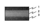
図1に示すように、本発明の製造方法が適用される一つの実施の形態としての全固体電池の積層体10では、正極層1と固体電解質層2と負極層3とから構成される単電池が複数個、たとえば2個、集電体層4を介して直列に接続されている。全固体電池の積層体10の内部に配置される集電体層4は、正極層1と負極層3との間に設けられている。As shown in FIG. 1, an all-solid-
なお、正極層1と負極層3のそれぞれは固体電解質と電極活物質とを含み、固体電解質層2は固体電解質を含む。正極層1と負極層3のそれぞれは、電子伝導材料として、炭素、金属等を含んでもよい。Note that each of the
上記のように構成された全固体電池の積層体10のうち、少なくとも1個の単電池の積層体を製造するためには、本発明では、まず、正極層1または負極層3の少なくともいずれかのグリーンシートである第1のグリーンシートと、固体電解質層2のグリーンシートである第2のグリーンシートとを作製する(グリーンシート作製工程)。その後、第1のグリーンシートと第2のグリーンシートとを積層して積層体を形成する(積層体形成工程)。そして、積層体の少なくとも一方側の面に接触するようにセッターを配置して積層体を焼成する(焼成工程)。この焼成工程では、積層体の少なくとも一方側の面に接触するセッターの表面粗さが0.11μmRa以上50.13μmRa以下である。In order to manufacture a laminate of at least one single cell among the
なお、焼成工程において、積層体の両側の面に接触するようにセッターを配置して積層体をセッターで挟持した状態で焼成してもよい。また、図1に示す全固体電池の積層体10を製造するためには、正極層1、固体電解質層2、負極層3、および、集電体層4のそれぞれのグリーンシートを作製した後、これらのグリーンシートを正極層1、固体電解質層2、負極層3、集電体層4、正極層1、固体電解質層2、および、負極層3の順に積層して積層体10を形成し、積層体10の少なくとも一方側の面に接触するようにセッターを配置して積層体10を焼成すればよい。In the firing step, the setter may be disposed so as to be in contact with both surfaces of the laminate, and the laminate may be fired with the setter sandwiched therebetween. Moreover, in order to manufacture the all-solid-
表面粗さが0.11μm以上50.13μmRa以下のセッターを積層体の一方側の面、または両面に接触するように配置して積層体を焼成することにより、バインダとして作用する樹脂を効率的に除去し、残留炭素の発生を抑制することができる。その結果、全固体電池の内部短絡を抑制することができる。A setter having a surface roughness of 0.11 μm or more and 50.13 μmRa or less is disposed so as to be in contact with one side or both sides of the laminate, and the laminate is baked to efficiently produce a resin acting as a binder. It can be removed and the generation of residual carbon can be suppressed. As a result, an internal short circuit of the all solid state battery can be suppressed.
上記の作用効果は、表面粗さが0.11μm以上50.13μmRa以下のセッターを用いることにより、セッターと積層体との実質的な接触面積が減少し、その結果、樹脂の分解または気化により生じたガスが、セッターと積層体が隣接する接触界面から排出されやすくなるためと推定される。By using a setter having a surface roughness of 0.11 μm or more and 50.13 μmRa or less, the substantial contact area between the setter and the laminate is reduced, and as a result, the effect is caused by decomposition or vaporization of the resin. This is presumably because the gas is likely to be discharged from the contact interface where the setter and the laminate are adjacent.
セッターの表面粗さが0.11μmRa未満の場合、セッターと積層体との接触面積が大きすぎるため、残留炭素を十分に除去できなくなる恐れがある。セッターの表面粗さが50.13μmRaよりも大きいと、セッターの表面の凹凸により積層体の表面に損傷が生じる恐れがある。さらに、セッターの表面の凹部に積層体の表面部分が食い込むことにより、焼成工程の後、セッターと積層体が固着する恐れがある。If the surface roughness of the setter is less than 0.11 μmRa, the contact area between the setter and the laminate is too large, and there is a possibility that residual carbon cannot be removed sufficiently. If the surface roughness of the setter is larger than 50.13 μmRa, the surface of the laminate may be damaged by the unevenness of the surface of the setter. Furthermore, when the surface portion of the laminated body bites into the recesses on the surface of the setter, the setter and the laminated body may be fixed after the firing step.
短時間で効率的に残留炭素を除去し、かつ、損傷の少ない積層体を得るためには、セッターの表面粗さは1.04μmRa以上10.01μmRa以下であることが好ましい。In order to efficiently remove residual carbon in a short time and obtain a laminate with little damage, it is preferable that the setter has a surface roughness of 1.04 μmRa to 10.01 μmRa.
なお、表面粗さとしては、x軸をセッターの表面に沿ってとり、座標xにおける凹凸の大きさをf(x)で表した粗さ曲線から、そのx軸方向に基準長さLだけ抜き取り、この抜き取り部分の平均線から測定曲線までの偏差の絶対値を合算し、算術平均粗さを用いる。なお、算術平均粗さの算出は、JIS B0601‐2001に従い、オリンパス株式会社製の光学測定装置(型番:OLS4000)を用いて行うことができる。As the surface roughness, the x-axis is taken along the surface of the setter, and the reference length L is extracted in the x-axis direction from the roughness curve in which the unevenness at the coordinate x is represented by f (x). The absolute value of the deviation from the average line of the extracted portion to the measurement curve is added up, and the arithmetic average roughness is used. The arithmetic average roughness can be calculated using an optical measuring device (model number: OLS4000) manufactured by Olympus Corporation in accordance with JIS B0601-2001.
積層体形成工程では、正極層1、固体電解質層2、および、負極層3のグリーンシートを積層して単電池構造の積層体を形成してもよく、積層体形成工程において、集電体のグリーンシートを介在させて、上記の単電池構造の積層体を複数個、積層して複電池構造の積層体を形成してもよい。この場合、単電池構造の積層体を複数個、電気的に直列、または並列に積層してもよい。In the laminated body forming step, the green sheets of the
焼成工程では、セッターを介して積層体に圧力を加えた状態で積層体を焼成することが好ましい。圧力を加えた状態で積層体を焼成することにより、正極層1または負極層3と固体電解質層2とを隙間なく焼結によって接合しやすくなる。その結果、全固体電池の内部抵抗を低減させ、高い容量を得ることができる。In the firing step, it is preferable to fire the laminate in a state where pressure is applied to the laminate via a setter. By firing the laminate in a state where pressure is applied, the
また、焼成工程は、積層体を第1の焼成温度で焼成する第一焼成工程と、第一焼成工程の後、積層体を第2の焼成温度で焼成する第二焼成工程とを含み、第2の焼成温度が第1の焼成温度より高いことが好ましい。この場合、第一焼成工程において積層体を低温に保持することにより、脱脂処理を行うことができ、バインダとして作用する樹脂をより効率的に除去することができる。その後、第二焼成工程において積層体を高温に保持することにより、残留炭素の発生が抑制された全固体電池の積層体を得ることができる。これにより、全固体電池の内部短絡をより効果的に抑制することができる。The firing step includes a first firing step for firing the laminate at a first firing temperature, and a second firing step for firing the laminate at a second firing temperature after the first firing step. It is preferable that the firing temperature of 2 is higher than the first firing temperature. In this case, degreasing treatment can be performed by holding the laminate at a low temperature in the first firing step, and the resin acting as a binder can be more efficiently removed. Then, the laminated body of the all-solid-state battery by which generation | occurrence | production of residual carbon was suppressed can be obtained by hold | maintaining a laminated body at high temperature in a 2nd baking process. Thereby, the internal short circuit of an all-solid-state battery can be suppressed more effectively.
焼成工程で使用するセッターは、内部にポア(空隙)を有する多孔体であれば、その気孔率は特に限定されないが、気孔率が10体積%以上50体積%以下のセッターを用いることが好ましい。The setter used in the firing step is not particularly limited as long as it is a porous body having pores (voids) inside, but it is preferable to use a setter having a porosity of 10% by volume to 50% by volume.
セッターの材質は、積層体との反応または焼結による接合が少なく、高融点の材料であれば特に限定されないが、たとえば、炭化ケイ素(SiC)、窒化ケイ素(Si3N4)、窒化ホウ素(BN)、窒化アルミニウム(AlN)、酸化ベリリウム(BeO)、二ケイ化モリブデン(MoSi2)、窒化チタン(TiN)、ホウ化ジルコニウム(ZrB2)から選ばれる1種類以上のセラミックを含むことが好ましい。The material of the setter is not particularly limited as long as it is a material having a low melting point and a high melting point, such as silicon carbide (SiC), silicon nitride (Si3 N4 ), boron nitride ( BN), aluminum nitride (AlN), beryllium oxide (BeO), molybdenum disilicide (MoSi2 ), titanium nitride (TiN), and zirconium boride (ZrB2 ) are preferably included. .
セッターの熱伝導率は高いことが好ましい。セッターの熱伝導率は高いと、積層体の焼成時に、セッターに隣接する積層体の温度分布が均一になりやすい。具体的には、5W/m・K以上の熱伝導率を有するセッターを用いることが好ましい。The heat conductivity of the setter is preferably high. When the heat conductivity of the setter is high, the temperature distribution of the laminate adjacent to the setter tends to be uniform when the laminate is fired. Specifically, it is preferable to use a setter having a thermal conductivity of 5 W / m · K or more.
セッターの曲げ強度は高いことが好ましい。セッターの曲げ強度が高いと、焼成時に、セッターが破損または変形することを防止することができる。具体的には、20MPa以上の曲げ強度を有するセッターを用いることが好ましい。It is preferable that the bending strength of the setter is high. When the bending strength of the setter is high, the setter can be prevented from being damaged or deformed during firing. Specifically, it is preferable to use a setter having a bending strength of 20 MPa or more.
積層体形成工程で積層体を形成する方法は特に限定されないが、グリーンシートを順次、一枚ずつ重ね合わせて、グリーンシートに圧力を加えて積層すること等により、積層体を形成することができる。グリーンシートに加えられる圧力は、特に限定されないが、500kg/cm2以上5000kg/cm2以下の圧力をグリーンシートに加えることにより、緻密で剥がれの少ない積層体を形成することができる。The method of forming the laminate in the laminate formation step is not particularly limited, but the laminate can be formed by sequentially stacking the green sheets one by one and applying pressure to the green sheets to laminate them. . The pressure applied to the green sheet is not particularly limited. By applying a pressure of 500 kg / cm2 or more and 5000 kg / cm2 or less to the green sheet, a dense laminate with little peeling can be formed.
グリーンシートに圧力を加えながら加熱することにより、グリーンシートを積層してもよい。加熱する温度は特に限定されないが、20℃以上100℃以下の温度で、樹脂を軟化させながら、グリーンシートを積層することが好ましいThe green sheets may be laminated by heating while applying pressure to the green sheets. Although the temperature to heat is not specifically limited, It is preferable to laminate | stack a green sheet, softening resin at the temperature of 20 to 100 degreeC.
上記のグリーンシートを成形する方法は特に限定されないが、ダイコーター、コンマコーター、スクリーン印刷等を使用することができる。The method for forming the green sheet is not particularly limited, but a die coater, a comma coater, screen printing, or the like can be used.
グリーンシートを成形するためのスラリーは、高分子材料を溶剤に溶解した有機ビヒクルと、正極活物質、負極活物質、固体電解質、または、集電体材料とを湿式混合することによって作製することができる。湿式混合ではメディアを用いることができ、具体的には、ボールミル法、ビスコミル法等を用いることができる。一方、メディアを用いない湿式混合方法を用いてもよく、サンドミル法、高圧ホモジナイザー法、ニーダー分散法等を用いることができる。A slurry for forming a green sheet can be prepared by wet-mixing an organic vehicle in which a polymer material is dissolved in a solvent and a positive electrode active material, a negative electrode active material, a solid electrolyte, or a current collector material. it can. Media can be used in wet mixing, and specifically, a ball mill method, a viscomill method, or the like can be used. On the other hand, a wet mixing method that does not use media may be used, and a sand mill method, a high-pressure homogenizer method, a kneader dispersion method, or the like can be used.
スラリーは可塑剤を含んでもよい。可塑剤の種類は特に限定されないが、フタル酸ジオクチル、フタル酸ジイソノニル等のフタル酸エステル等を使用してもよい。The slurry may contain a plasticizer. Although the kind of plasticizer is not particularly limited, phthalic acid esters such as dioctyl phthalate and diisononyl phthalate may be used.
グリーンシートを積層する方法は特に限定されないが、熱間等方圧プレス(HIP)、冷間等方圧プレス(CIP)、静水圧プレス(WIP)等を使用してグリーンシートを積層することができる。The method of laminating the green sheets is not particularly limited, but the green sheets can be laminated using a hot isostatic press (HIP), a cold isostatic press (CIP), a hydrostatic press (WIP), or the like. it can.
焼成工程では、雰囲気は特に限定されないが、電極活物質に含まれる遷移金属の価数が変化しない条件で行うことが好ましい。In the firing step, the atmosphere is not particularly limited, but it is preferably performed under conditions that do not change the valence of the transition metal contained in the electrode active material.
なお、本発明の製造方法が適用される全固体電池の積層体10の正極層1または負極層3に含まれる電極活物質の種類は限定されないが、正極活物質としては、Li3V2(PO4)3等のナシコン型構造を有するリチウム含有リン酸化合物、LiFePO4、LiMnPO4等のオリビン型構造を有するリチウム含有リン酸化合物、LiCoO2、LiCo1/3Ni1/3Mn1/3O2等の層状化合物、LiMn2O4、LiNi0.5Mn1.5O4等のスピネル型構造を有するリチウム含有化合物を用いることができる。In addition, although the kind of electrode active material contained in the
負極活物質としては、MOx(MはTi、Si、Sn、Cr、Fe、NbおよびMoからなる群より選ばれた少なくとも1種以上の元素であり、xは0.9≦x≦2.0の範囲内の数値である)で表わされる組成を有する化合物を用いることができる。たとえば、TiO2とSiO2、等の異なる元素Mを含むMOxで表わされる組成を有する2つ以上の活物質を混合した混合物を用いてもよい。また、負極活物質としては、黒鉛-リチウム化合物、Li‐Al等のリチウム合金、Li3V2(PO4)3、Li3Fe2(PO4)3、Li4Ti5O12等の酸化物、等を用いることができる。As the negative electrode active material, MOx (M is at least one element selected from the group consisting of Ti, Si, Sn, Cr, Fe, Nb and Mo, and x is 0.9 ≦ x ≦ 2.0. A compound having a composition represented by the following formula can be used. For example, a mixture in which two or more active materials having a composition represented by MOx containing different elements M such as TiO2 and SiO2 may be used. As the negative electrode active material, graphite-lithium compounds, lithium alloys such as Li-Al, oxidation of Li3 V2 (PO4 )3 , Li3 Fe2 (PO4 )3 , Li4 Ti5 O12, etc. Thing, etc. can be used.
また、本発明の製造方法が適用される全固体電池の積層体10の正極層1、負極層3、または、固体電解質層2に含まれる固体電解質の種類は限定されないが、固体電解質としては、ナシコン型構造を有するリチウム含有リン酸化合物を用いることができる。ナシコン型構造を有するリチウム含有リン酸化合物は、化学式LixMy(PO4)3(化学式中、xは1≦x≦2、yは1≦y≦2の範囲内の数値であり、MはTi、Ge、Al、GaおよびZrからなる群より選ばれた1種以上の元素である)で表わされる。この場合、上記化学式においてPの一部をB、Si等で置換してもよい。たとえば、Li1.5Al0.5Ge1.5(PO4)3とLi1.2Al0.2Ti1.8(PO4)3等の異なる組成を有する2つ以上のナシコン型構造を有するリチウム含有リン酸化合物を混合した混合物を用いてもよい。Further, the type of the solid electrolyte contained in the
また、上記の固体電解質に用いられるナシコン型構造を有するリチウム含有リン酸化合物としては、ナシコン型構造を有するリチウム含有リン酸化合物の結晶相を含む化合物、または、熱処理によりナシコン型構造を有するリチウム含有リン酸化合物の結晶相を析出するガラスを用いてもよい。The lithium-containing phosphate compound having a NASICON structure used in the solid electrolyte is a compound containing a crystal phase of a lithium-containing phosphate compound having a NASICON structure or a lithium-containing phosphate having a NASICON structure by heat treatment. You may use the glass which precipitates the crystal phase of a phosphoric acid compound.
なお、上記の固体電解質に用いられる材料としては、ナシコン型構造を有するリチウム含有リン酸化合物以外に、イオン伝導性を有し、電子伝導性が無視できるほど小さい材料を用いることが可能である。このような材料として、たとえば、ハロゲン化リチウム、窒化リチウム、リチウム酸素酸塩、および、これらの誘導体を挙げることができる。また、リン酸リチウム(Li3PO4)等のLi‐P‐O系化合物、リン酸リチウムに窒素を混ぜたLIPON(LiPO4-xNx)、Li4SiO4等のLi‐Si‐O系化合物、Li‐P‐Si‐O系化合物、Li‐V‐Si‐O系化合物、La0.51Li0.35TiO2.94、La0.55Li0.35TiO3、Li3xLa2/3-xTiO3等のぺロブスカイト型構造を有する化合物、Li、La、Zrを有するガーネット型構造を有する化合物等を挙げることができる。In addition, as a material used for said solid electrolyte, it is possible to use the material which has ion conductivity and is so small that electronic conductivity can be disregarded other than the lithium-containing phosphate compound which has a NASICON structure. Examples of such a material include lithium halide, lithium nitride, lithium oxyacid salt, and derivatives thereof. In addition, Li-PO system compounds such as lithium phosphate (Li3 PO4 ), LIPON (LiPO4−x Nx ) in which nitrogen is mixed with lithium phosphate, and Li—Si—O such as Li4 SiO4Such as La-based compounds, Li-P-Si-O based compounds, Li-V-Si-O based compounds, La0.51 Li0.35 TiO2.94 , La0.55 Li0.35 TiO3 , Li3x La2 / 3-x TiO3 Examples thereof include compounds having a lobskite structure, compounds having a garnet structure having Li, La, and Zr.
本発明の製造方法が適用される全固体電池の積層体10の正極層1、固体電解質層2、または、負極層3の少なくとも一つの材料が、ナシコン型構造のリチウム含有リン酸化合物からなる固体電解質を含むことが好ましい。この場合、全固体電池の電池動作に必須となる高いイオン伝導性を得ることができる。また、ナシコン型構造のリチウム含有リン酸化合物の組成を有するガラス、または、ガラスセラミックスを固体電解質として用いると、焼成工程においてガラス相の粘性流動により、より緻密な焼結体を容易に得ることができるため、ガラス、または、ガラスセラミックスの形態で固体電解質の出発原料を準備することが特に好ましい。A solid in which at least one material of the
また、本発明の製造方法が適用される全固体電池の積層体10の正極層1または負極層3の少なくとも一つの材料が、リチウム含有リン酸化合物からなる電極活物質を含むことが好ましい。この場合、焼成工程において電極活物質が相変化すること、または、電極活物質が固体電解質と反応することをリン酸骨格の高い温度安定性により容易に抑制することができるため、全固体電池の容量を高くすることができる。また、リチウム含有リン酸化合物からなる電極活物質と、ナシコン型構造のリチウム含有リン酸化合物からなる固体電解質とを組み合わせて用いると、焼成工程において電極活物質と固体電解質との反応を抑制することができるとともに、両者の良好な接触を得ることができるため、上記のように電極活物質と固体電解質の材料を組み合わせて用いることが特に好ましい。Moreover, it is preferable that at least one material of the
さらに、本発明の製造方法が適用される全固体電池の積層体10の集電体層4は電子伝導材料を含む。電子伝導材料は、導電性酸化物、金属、および、炭素材料からなる群より選ばれた少なくとも一種を含むことが好ましい。Further, the
次に、本発明の実施例を具体的に説明する。なお、以下に示す実施例は一例であり、本発明は下記の実施例に限定されるものではない。Next, specific examples of the present invention will be described. In addition, the Example shown below is an example and this invention is not limited to the following Example.
以下、本発明の製造方法に従って作製された全固体電池について説明する。Hereinafter, an all-solid battery manufactured according to the manufacturing method of the present invention will be described.
(セッターの作製)
まず、以下の表1に示す表面粗さを有するセッターを以下の工程に従って作製した。(Preparation of setter)
First, a setter having the surface roughness shown in Table 1 below was produced according to the following steps.
アルミナ(Al2O3)製のファイバーと炭化ケイ素(SiC)の粒子を主材とするセラミックス粉を、ボールミルで湿式混合してスラリーを作製した。得られたスラリーを脱水処理して電気炉中で1100℃の温度で仮焼した。この仮焼粉末100重量部に対して、5重量部のポリビニルアルコール樹脂を加え、ボールミルで湿式混合してスラリーを作製した。このスラリーをスプレードライヤーによって乾燥させることにより造粒した。得られた造粒粉末に、プレス成形により1トン/cm2の圧力を加えて薄板状に成形した。得られた成形体の大きさは、50mm×50m×厚み2.0mmであった。この成形体を1200℃の温度で焼成した。このようにしてセッターを作製した。A ceramic powder mainly composed of alumina (Al2 O3 ) fibers and silicon carbide (SiC) particles was wet mixed by a ball mill to prepare a slurry. The obtained slurry was dehydrated and calcined at a temperature of 1100 ° C. in an electric furnace. To 100 parts by weight of the calcined powder, 5 parts by weight of polyvinyl alcohol resin was added and wet mixed by a ball mill to prepare a slurry. This slurry was granulated by drying with a spray dryer. The resulting granulated powder was molded into a thin plate by applying a pressure of 1 ton / cm2 by press molding. The size of the obtained molded body was 50 mm × 50 m × thickness 2.0 mm. The molded body was fired at a temperature of 1200 ° C. Thus, a setter was produced.
得られたセッターの表面粗さを次のようにして調整した。The surface roughness of the obtained setter was adjusted as follows.
ラップ定盤とセッターとの間にダイヤモンド砥粒と研磨液を導入し、ラップ定盤とセッターとをこすり合わせながら回転させることによってラップした。これにより、セッターの大きなうねりを取り除くとともに、表面粗さを所望の値にした。このとき、ラップ定盤の回転数を30~200rpmとし、ラップの時間を調整することによって、セッターの表面粗さを以下の表1に示す所望の値に調整した。The diamond abrasive grains and polishing liquid were introduced between the lapping platen and the setter, and lapping was performed by rotating the lapping platen and the setter while rubbing. As a result, large setter waviness was removed and the surface roughness was set to a desired value. At this time, the surface roughness of the setter was adjusted to the desired value shown in Table 1 below by adjusting the rotation speed of the lapping platen to 30 to 200 rpm and adjusting the lapping time.
(材料の準備)
次に、全固体電池を作製するために、固体電解質層、正極層、負極層、および、集電体層の出発原料として以下の材料を準備した。(Preparation of materials)
Next, in order to produce an all-solid battery, the following materials were prepared as starting materials for the solid electrolyte layer, the positive electrode layer, the negative electrode layer, and the current collector layer.
固体電解質材料としてLi1.5Al0.5Ge1.5(PO4)3の組成を有するガラス粉末、正極活物質材料としてLi3V2(PO4)3の組成を有するナシコン型構造の結晶相を含む粉末、負極活物質材料としてアナターゼ型の結晶構造を持つ二酸化チタン粉末、電子伝導性材料として炭素粉末、焼結性材料としてLi1.0Ge2.0(PO4)3の組成を有するガラスセラミックス粉末を準備した。A glass powder having a composition of Li1.5 Al0.5 Ge1.5 (PO4 )3 as a solid electrolyte material, a powder containing a crystal phase of NASICON structure having a composition of Li3 V2 (PO4 )3 as a positive electrode active material, A titanium dioxide powder having an anatase type crystal structure as a negative electrode active material, a carbon powder as an electron conductive material, and a glass ceramic powder having a composition of Li1.0 Ge2.0 (PO4 )3 as a sinterable material were prepared.
上記の材料を用いて、以下の方法で各スラリーを作製した。Each slurry was prepared by the following method using the above materials.
(スラリーの作製)
以下に示す主材、アクリル樹脂およびアルコールを、100:15:140の質量比率で秤量した。そして、アクリル樹脂をアルコールに溶解した後、主材とメディアとともに容器に封入して容器を回転させた後、容器からメディアを取り出すことにより、各スラリーを作製した。(Preparation of slurry)
The main material, acrylic resin and alcohol shown below were weighed at a mass ratio of 100: 15: 140. And after melt | dissolving an acrylic resin in alcohol, after enclosing in a container with a main material and a medium and rotating a container, each slurry was produced by taking out the medium from a container.
主材としては、固体電解質スラリーでは固体電解質材料、正極スラリーでは正極活物質材料、電子伝導性材料および固体電解質材料を45:15:40の質量比率で混合した粉末、負極スラリーでは負極活物質材料、電子伝導性材料および固体電解質材料を45:15:40の質量比率で混合した粉末、集電体スラリーでは電子伝導性材料および焼結性材料を10:90の質量比率で混合した粉末を使用した。Main materials are solid electrolyte material for solid electrolyte slurry, positive electrode active material for positive electrode slurry, powder mixed with electron conductive material and solid electrolyte material in mass ratio of 45:15:40, negative electrode active material for negative electrode slurry A powder in which an electron conductive material and a solid electrolyte material are mixed at a mass ratio of 45:15:40, and a powder in which a current collector slurry is a mixture of an electron conductive material and a sinterable material in a mass ratio of 10:90 is used. did.
得られた各スラリーを用いて各グリーンシートを以下の方法で作製した。Each green sheet was produced by the following method using each obtained slurry.
(グリーンシート作製工程)
ドクターブレード法を用いてポリエチレンテレフタレート(PET)フィルムの上に各スラリーを塗工し、40℃の温度に加熱したホットプレートの上で乾燥し、厚みが10μmになるようにシート状に成形し、35mm×35mmの大きさに切断してシートを作製した。(Green sheet production process)
Each slurry was coated on a polyethylene terephthalate (PET) film using a doctor blade method, dried on a hot plate heated to a temperature of 40 ° C., and formed into a sheet shape with a thickness of 10 μm. A sheet was cut into a size of 35 mm × 35 mm.
得られた各グリーンシートを用いて、積層体を以下の方法で形成した。Using each obtained green sheet, a laminate was formed by the following method.
(積層体形成工程)
PETフィルムから剥がした各グリーンシートを一枚ずつ重ねるごとに、2枚のステンレス鋼製の平板で挟むことにより、順次、熱圧着した。熱圧着は、ステンレス鋼製の平板を60℃の温度に加熱し、1000kg/cm2の圧力を加えることにより行った。その後、熱圧着されたグリーンシートの積層体をポリエチレン製のフィルム容器に真空状態で封入し、ポリエチレン製のフィルム容器を水中に浸漬して水に圧力を加えた。等方圧プレスにより水に200MPaの圧力を加えた。このようにして積層体10を形成した。(Laminate formation process)
As each green sheet peeled off from the PET film was stacked one by one, it was thermocompression bonded sequentially by sandwiching it between two stainless steel flat plates. The thermocompression bonding was performed by heating a flat plate made of stainless steel to a temperature of 60 ° C. and applying a pressure of 1000 kg / cm2 . Then, the laminated body of the green sheet | seat pressure-bonded was sealed in the polyethylene film container in the vacuum state, the polyethylene film container was immersed in water, and the pressure was applied to water. A pressure of 200 MPa was applied to the water by an isotropic pressure press. Thus, the
なお、積層体10は、図1に示すように、2つの単電池を電気的に直列に接続するように積層した構造を有し、2つの単電池が、2枚の集電体グリーンシートからなる集電体層4を介して直列に接続されている。各単電池は、2枚の正極グリーンシートからなる正極層1と、5枚の固体電解質グリーンシートからなる固体電解質層2と、1枚の負極シートからなる負極層3とから構成される。In addition, as shown in FIG. 1, the
(積層体の切断)
平面の大きさが35mm×35mmの積層体10を10mm×10mmの大きさに切断し、9個の積層体10を作製した。(Cutting the laminate)
The laminate 10 having a plane size of 35 mm × 35 mm was cut into a size of 10 mm × 10 mm to produce nine
以下の工程では、平面の大きさが35mm×35mmの一つの積層体から切り分けられた平面が10mm×10mmの大きさの9個の積層体全部に対して同じ条件で焼成と評価を以下の方法で行った。In the following steps, firing and evaluation are performed under the same conditions for all nine laminates having a plane size of 10 mm × 10 mm cut from a single laminate having a plane size of 35 mm × 35 mm. I went there.
(焼成工程)
表1に示す種々の表面粗さを有するセッターを2枚用いて、積層体10を2枚のセッターで挟持し、10kg/cm2の圧力をセッターに加えた状態で焼成した。焼成工程は、以下の二段階で行った。(Baking process)
Using two setters having various surface roughnesses shown in Table 1, the laminate 10 was sandwiched between thetwo setters and fired in a state where a pressure of 10 kg / cm2 was applied to the setter. The firing process was performed in the following two stages.
第一焼成工程(脱脂工程):空気を流通させた雰囲気中で、室温から400℃の温度まで徐々に昇温し、400℃の温度にて表1に示す所定時間で保持した後、室温まで徐冷した。First firing step (degreasing step): In an atmosphere in which air is circulated, the temperature is gradually raised from room temperature to a temperature of 400 ° C., held at a temperature of 400 ° C. for a predetermined time shown in Table 1, and then to room temperature. Slowly cooled.
第二焼成工程:第一焼成工程の後、窒素を流通させた雰囲気中で、室温から700℃の温度まで徐々に昇温し、700℃の温度で10時間保持した後、室温まで徐冷した。Second firing step: After the first firing step, the temperature was gradually raised from room temperature to 700 ° C. in an atmosphere in which nitrogen was circulated, held at 700 ° C. for 10 hours, and then gradually cooled to room temperature. .
その後、積層体をセッターから取り外した。After that, the laminate was removed from the setter.
このようにして作製された全固体電池の積層体10を次のようにして評価した。The
(評価1)
焼成後の積層体10の側面を光学顕微鏡(600倍)で観察し、固体電解質層2の色を観察した。(Evaluation 1)
The side surface of the fired
(評価2)
焼成後の積層体10の両面に、銀(Ag)ペーストを塗布し、その金属ペースト中に銅(Cu)製のリード端子を埋没させた状態で乾燥させて、正極端子と負極端子を形成した。(Evaluation 2)
A silver (Ag) paste was applied to both surfaces of the fired
正負極端子が取り付けられた全固体電池の積層体10に、アルゴンガス雰囲気中で、5μAの電流で6Vの電圧まで充電した後、6Vの電圧で10時間保持した。そして、電池電圧の低下速度が0.1mV/秒に低下するまで放置した(充電休止)。その後、5μAの電流で0Vの電圧まで放電した。The
図2に、表面粗さが4.95μmRaのセッターを用い、空気を流通させた雰囲気中で400℃の温度で30分間保持して脱脂工程を実施した全固体電池の積層体10の充放電曲線(2サイクル目)を、一例として示す。FIG. 2 shows a charge / discharge curve of a
図2から、充電休止後の電池電圧は約5.6Vであることがわかる。この電池電圧の値は、正極活物質材料と負極活物質材料から推定される電池電圧と概ね一致する。さらに、充放電曲線の形状にも特に問題はなく、良好に充電と放電が行われていることがわかる。これらのことから、この例の全固体電池の積層体10は、内部短絡を起こしておらず、全固体電池として良好に充放電していることがわかる。FIG. 2 shows that the battery voltage after the suspension of charging is about 5.6V. The value of the battery voltage generally matches the battery voltage estimated from the positive electrode active material and the negative electrode active material. Further, there is no particular problem with the shape of the charge / discharge curve, and it can be seen that charging and discharging are performed satisfactorily. From these, it can be seen that the all-solid-
内部短絡の有無の判断については、図2の充放電曲線を基準として、以下の4つの条件をすべて満たす場合に内部短絡があると判断した。Regarding the determination of the presence or absence of an internal short circuit, it was determined that there was an internal short circuit when all of the following four conditions were satisfied based on the charge / discharge curve of FIG.
(i)充電時間(電池電圧が6Vに達するまでの時間)が図2の2倍以上の場合
(ii)充電休止中に電池電圧が5V以下まで低下した場合
(iii)放電時間が図2の半分以下である場合
(iv)上記の評価1で固体電解質層2の色が黒色である場合(I) When the charging time (time until the battery voltage reaches 6V) is more than twice that of FIG. 2 (ii) When the battery voltage drops to 5V or less during charging suspension (iii) The discharging time of FIG. When it is less than half (iv) When the color of the
(評価結果A)
上記の評価結果として、用いたセッターの表面粗さと脱脂工程の保持時間とについて同じ条件で焼成された9個の積層体10のうち、内部短絡が認められた個数を表1に示す。(Evaluation result A)
Table 1 shows the number of internal short circuits observed among the nine

表1から、表面粗さが0.04μmRaのセッターを用いて作製された全固体電池では、脱脂工程の保持時間に無関係に、概ね全数に内部短絡が認められたことがわかる。また、表面粗さが0.11μmRa以上のセッターを用いて焼成された全固体電池では、脱脂工程の保持時間に無関係に、全数に内部短絡が認められなかったことがわかる。これらのことから、表面粗さが0.11μmRa以上のセッターを用いることによって、全固体電池の内部短絡を抑制することができることを確認した。From Table 1, it can be seen that in all solid state batteries manufactured using a setter having a surface roughness of 0.04 μmRa, almost all internal short circuits were observed regardless of the holding time of the degreasing process. Moreover, in the all-solid-state battery baked using the setter whose surface roughness is 0.11 micrometer Ra or more, it turns out that an internal short circuit was not recognized by all irrespective of the holding time of a degreasing process. From these, it was confirmed that the internal short circuit of the all-solid-state battery can be suppressed by using a setter having a surface roughness of 0.11 μmRa or more.
表面粗さが50.13μmRaのセッターを用いて焼成された積層体10では、脱脂工程の保持時間に無関係に、セッターの表面粗さによる凹凸が積層体10の表面に生じた。また、表面粗さが80.59μmRaのセッターを用いて焼成された積層体10では、脱脂工程の保持時間が長いほど、セッターと積層体とが強固に固着し、セッターを取り外す過程で、積層体の表面が一部脱落した。なお、表面粗さが80.59μmRaのセッターを用いて焼成された全固体電池の積層体10では、積層体が破損したとみなし、評価2を実施しなかった。In the laminate 10 baked using a setter having a surface roughness of 50.13 μmRa, irregularities due to the setter surface roughness were generated on the surface of the laminate 10 regardless of the holding time of the degreasing step. Moreover, in the
評価1の例として、表面粗さが0.04μmRaと0.11μmRaのセッターを用い、脱脂工程の保持時間を30分として焼成された積層体10の側面の光学顕微鏡写真(固体電解質層2の付近)をそれぞれ、図3と図4に示す。As an example of
表面粗さが0.11μmRaのセッターを用いて焼成した積層体(図4)に比べて、表面粗さが0.04μmRaのセッターを用いて焼成した積層体(図3)の固体電解質層2は明らかに黒色であり、固体電解質層2の内部に残留炭素が存在することが示唆された。なお、図示していないが、表面粗さが0.04μmRaのセッターを用いて焼成した積層体は、内部短絡の有無に無関係に、全数、図3と同様の黒色の固体電解質層2が観察された。The
次に、表1に示す評価結果にて内部短絡が認められなかった表面粗さが0.11μmRa、1.04μmRa、4.95μmRaのセッターを用いて、9個の積層体全部に対して同じ条件で焼成工程と評価を以下の方法で行った。Next, in the evaluation results shown in Table 1, the same conditions were applied to all nine laminates using setters with surface roughness of 0.11 μmRa, 1.04 μmRa and 4.95 μmRa where no internal short circuit was observed. The firing process and evaluation were performed by the following method.
以下の表2に示す種々の表面粗さを有するセッターを2枚用いて、積層体10を2枚のセッターで挟持し、10kg/cm2の圧力をセッターに加えた状態で焼成した。焼成工程は、以下の二段階で行った。Using two setters having various surface roughnesses shown in Table 2 below, the laminate 10 was sandwiched between thetwo setters and fired in a state where a pressure of 10 kg / cm2 was applied to the setter. The firing process was performed in the following two stages.
第一焼成工程(脱脂工程):窒素を流通させた雰囲気中で、室温から400℃の温度まで徐々に昇温し、400℃の温度にて表1に示す所定時間で保持した後、室温まで徐冷した。First firing step (degreasing step): In an atmosphere in which nitrogen is circulated, the temperature is gradually raised from room temperature to a temperature of 400 ° C., held at a temperature of 400 ° C. for a predetermined time shown in Table 1, and then to room temperature. Slowly cooled.
第二焼成工程:第一焼成工程の後、窒素を流通させた雰囲気中で、室温から700℃の温度まで徐々に昇温し、700℃の温度で10時間保持した後、室温まで徐冷した。Second firing step: After the first firing step, the temperature was gradually raised from room temperature to 700 ° C. in an atmosphere in which nitrogen was circulated, held at 700 ° C. for 10 hours, and then gradually cooled to room temperature. .
その後、積層体をセッターから取り外した。After that, the laminate was removed from the setter.
このようにして作製された全固体電池の積層体10を上記の評価2に従って評価した。The
(評価結果B)
上記の評価結果として、用いたセッターの表面粗さと脱脂工程の保持時間とについて同じ条件で焼成された9個の積層体10のうち、内部短絡が認められた個数を表2に示す。(Evaluation result B)
Table 2 shows the number of internal short circuits observed among the nine

窒素を流通させた雰囲気中での脱脂工程は、空気雰囲気中の酸素を用いた樹脂の燃焼反応が起こらないため、空気を流通させた雰囲気中での脱脂工程に比べて、残留炭素を十分に除去するために要する脱脂工程の保持時間が長くなるものと考えられる。In the degreasing process in the atmosphere in which nitrogen is circulated, the resin combustion reaction using oxygen in the air atmosphere does not occur, so the residual carbon is sufficient compared to the degreasing process in the atmosphere in which air is circulated. It is thought that the holding time of the degreasing process required for removing becomes longer.
上記のことを実証するものとして、表2から、表面粗さが0.11μmRaのセッターを用いて作製された全固体電池の積層体10では、脱脂工程の保持時間が15~30分の場合、9個のうち1~2個に内部短絡が認められたことがわかる。また、表面粗さが1.04μmRa以上のセッターを用いて作製された全固体電池の積層体10では、保持時間に無関係に、全数に内部短絡が認められなかったことがわかる。これらのことから、表面粗さが1.04μmRa以上のセッターを用いることによって、窒素雰囲気中であっても、残留炭素をより効果的に除去することができ、全固体電池の内部短絡をより効果的に抑制することができることを確認した。As proof of the above, from Table 2, in the all-
以上の評価結果から、0.11μmRa以上50.13μmRa以下のセッターを用いて積層体を焼成することによって、内部短絡を抑制し、セッターとの固着により積層体を破損することなく、全固体電池の積層体を作製できることを確認した。また、表面粗さが1.04μmRa以上10.01μmRa以下のセッターを用いて積層体を焼成すると、短い脱脂時間でも、窒素雰囲気中でも、効率的に残留炭素を除去して内部短絡を抑制することができるとともに、積層体の表面にセッターの表面粗さによる凹凸を生じさせることがないため、特に好ましいことを確認した。From the above evaluation results, by firing the laminate using a setter of 0.11 μmRa or more and 50.13 μmRa or less, an internal short circuit is suppressed and the laminate is not damaged by fixing with the setter. It was confirmed that a laminate could be produced. In addition, when the laminate is fired using a setter having a surface roughness of 1.04 μmRa or more and 10.01 μmRa or less, it can effectively remove residual carbon and suppress internal short circuit even in a short degreasing time or in a nitrogen atmosphere. In addition, it was confirmed that it is particularly preferable because the surface of the laminate does not cause unevenness due to the surface roughness of the setter.
今回開示された実施の形態と実施例はすべての点で例示であって制限的なものではないと考慮されるべきである。本発明の範囲は以上の実施の形態と実施例ではなく、請求の範囲によって示され、請求の範囲と均等の意味および範囲内でのすべての修正と変形を含むものであることが意図される。It should be considered that the embodiments and examples disclosed herein are illustrative and non-restrictive in every respect. The scope of the present invention is shown not by the above embodiments and examples but by the claims, and is intended to include all modifications and variations within the meaning and scope equivalent to the claims.
本発明の全固体電池の製造方法では、セッターが接触する積層体の少なくとも一方側の面の表面粗さを所定の値の範囲内に限定することにより、全固体電池の内部短絡を抑制することができるので、本発明は全固体電池の製造に特に有用である。In the all-solid-state battery manufacturing method of the present invention, the internal roughness of the all-solid-state battery is suppressed by limiting the surface roughness of at least one surface of the laminate in contact with the setter within a predetermined value range. Therefore, the present invention is particularly useful for manufacturing all-solid-state batteries.
1:正極層、2:固体電解質層、3:負極層、4:集電体層、10:積層体。
1: positive electrode layer, 2: solid electrolyte layer, 3: negative electrode layer, 4: current collector layer, 10: laminate.
Claims (7)
Translated fromJapanese前記第1のグリーンシートと前記第2のグリーンシートとを積層して積層体を形成する積層体形成工程と、
前記積層体の少なくとも一方側の面に接触するようにセッターを配置して前記積層体を焼成する焼成工程と、を備え、
前記焼成工程において、前記積層体の少なくとも一方側の面に接触する前記セッターの表面粗さが0.11μmRa以上50.13μmRa以下である、全固体電池の製造方法。A green sheet production step of producing a first green sheet that is a green sheet of at least one of a positive electrode layer and a negative electrode layer, and a second green sheet that is a green sheet of a solid electrolyte layer;
A laminated body forming step of laminating the first green sheet and the second green sheet to form a laminated body;
A firing step of firing the laminate by disposing a setter so as to be in contact with at least one surface of the laminate,
The manufacturing method of the all-solid-state battery whose surface roughness of the said setter which contacts the surface of the at least one side of the said laminated body is 0.11 micrometer Ra or more and 50.13 micrometer Ra or less in the said baking process.
前記積層体を第1の焼成温度で焼成する第一焼成工程と、
前記第一焼成工程の後、前記積層体を第2の焼成温度で焼成する第二焼成工程とを含み、前記第2の焼成温度が前記第1の焼成温度より高い、請求項1から請求項3までのいずれか1項に記載の全固体電池の製造方法。The firing step includes
A first firing step of firing the laminate at a first firing temperature;
The second firing step of firing the laminated body at a second firing temperature after the first firing step, wherein the second firing temperature is higher than the first firing temperature. 4. The method for producing an all-solid battery according to any one of items 3 to 3.
The all-solid-state battery manufactured by the manufacturing method of any one of Claim 1- Claim 6.
Priority Applications (3)
| Application Number | Priority Date | Filing Date | Title |
|---|---|---|---|
| CN201280035534.7ACN103688404B (en) | 2011-07-20 | 2012-07-13 | All-solid-state battery and manufacture method thereof |
| JP2013524699AJP5742941B2 (en) | 2011-07-20 | 2012-07-13 | All-solid battery and method for manufacturing the same |
| US14/157,673US10164287B2 (en) | 2011-07-20 | 2014-01-17 | All-solid battery and manufacturing method therefor |
Applications Claiming Priority (2)
| Application Number | Priority Date | Filing Date | Title |
|---|---|---|---|
| JP2011158706 | 2011-07-20 | ||
| JP2011-158706 | 2011-07-20 |
Related Child Applications (1)
| Application Number | Title | Priority Date | Filing Date |
|---|---|---|---|
| US14/157,673ContinuationUS10164287B2 (en) | 2011-07-20 | 2014-01-17 | All-solid battery and manufacturing method therefor |
Publications (1)
| Publication Number | Publication Date |
|---|---|
| WO2013011931A1true WO2013011931A1 (en) | 2013-01-24 |
Family
ID=47558109
Family Applications (1)
| Application Number | Title | Priority Date | Filing Date |
|---|---|---|---|
| PCT/JP2012/067884CeasedWO2013011931A1 (en) | 2011-07-20 | 2012-07-13 | All solid-state battery and method of manufacturing same |
Country Status (4)
| Country | Link |
|---|---|
| US (1) | US10164287B2 (en) |
| JP (1) | JP5742941B2 (en) |
| CN (1) | CN103688404B (en) |
| WO (1) | WO2013011931A1 (en) |
Cited By (1)
| Publication number | Priority date | Publication date | Assignee | Title |
|---|---|---|---|---|
| JP2019140065A (en)* | 2018-02-15 | 2019-08-22 | Fdk株式会社 | Method for manufacturing all-solid battery |
Families Citing this family (26)
| Publication number | Priority date | Publication date | Assignee | Title |
|---|---|---|---|---|
| US9362546B1 (en) | 2013-01-07 | 2016-06-07 | Quantumscape Corporation | Thin film lithium conducting powder material deposition from flux |
| HUE056765T2 (en) | 2013-10-07 | 2022-03-28 | Quantumscape Battery Inc | Bilayers and trilayers comprising lithium-stuffed garnet films and a method for sintering a thin an free standing lithium-stuffed garnet film |
| KR102643560B1 (en) | 2015-04-16 | 2024-03-07 | 퀀텀스케이프 배터리, 인코포레이티드 | Setter plates for solid electrolyte fabrication and methods of using the same to prepare dense solid electrolytes |
| CN107851774A (en) | 2015-07-21 | 2018-03-27 | 昆腾斯科普公司 | Methods and materials for casting and sintering green garnet films |
| US9966630B2 (en) | 2016-01-27 | 2018-05-08 | Quantumscape Corporation | Annealed garnet electrolyte separators |
| EP3455892B1 (en) | 2016-05-13 | 2024-02-07 | QuantumScape Battery, Inc. | Solid electrolyte separator bonding agent |
| US10734676B2 (en) | 2016-06-30 | 2020-08-04 | Wildcat Discovery Technologies, Inc | Solid electrolyte compositions |
| WO2018006025A1 (en) | 2016-06-30 | 2018-01-04 | Wildcat Discovery Technologies, Inc. | Electrode compositions for solid-state batteries |
| US11158880B2 (en) | 2016-08-05 | 2021-10-26 | Quantumscape Battery, Inc. | Translucent and transparent separators |
| US11916200B2 (en) | 2016-10-21 | 2024-02-27 | Quantumscape Battery, Inc. | Lithium-stuffed garnet electrolytes with a reduced surface defect density and methods of making and using the same |
| WO2018098176A1 (en)* | 2016-11-23 | 2018-05-31 | Wildcat Discovery Technologies, Inc. | Solid electrolyte compositions for electrochemical cells |
| KR102718465B1 (en) | 2016-12-21 | 2024-10-15 | 코닝 인코포레이티드 | Sintering system and sintered articles |
| WO2018186442A1 (en)* | 2017-04-04 | 2018-10-11 | 株式会社村田製作所 | All-solid-state battery, electronic device, electronic card, wearable device, and electric vehicle |
| EP4369453A3 (en) | 2017-06-23 | 2024-10-02 | QuantumScape Battery, Inc. | Lithium-stuffed garnet electrolytes with secondary phase inclusions |
| US10347937B2 (en) | 2017-06-23 | 2019-07-09 | Quantumscape Corporation | Lithium-stuffed garnet electrolytes with secondary phase inclusions |
| US11993710B2 (en) | 2017-06-30 | 2024-05-28 | Wildcat Discovery Technologies, Inc. | Composite solid state electrolyte and lithium ion battery containing the same |
| WO2019046652A1 (en)* | 2017-08-30 | 2019-03-07 | Cytomx Therapeutics, Inc. | Activatable anti-cd166 antibodies and methods of use thereof |
| WO2019090360A1 (en) | 2017-11-06 | 2019-05-09 | Quantumscape Corporation | Lithium-stuffed garnet thin films and pellets having an oxyfluorinated and/or fluorinated surface and methods of making and using the thin films and pellets |
| US10749199B2 (en)* | 2017-11-29 | 2020-08-18 | International Business Machines Corporation | Li1+xAlxTi2-x(PO4)3 solid-state thin film electrolyte for 3D microbattery and method of fabrication |
| JP6948545B2 (en)* | 2018-01-17 | 2021-10-13 | 株式会社エンビジョンAescジャパン | Lithium-ion battery electrodes and lithium-ion batteries |
| JP7070052B2 (en)* | 2018-04-27 | 2022-05-18 | トヨタ自動車株式会社 | All solid state battery |
| KR20210018419A (en) | 2018-06-06 | 2021-02-17 | 콴텀스케이프 코포레이션 | Solid-state battery |
| CN110212239A (en)* | 2019-05-21 | 2019-09-06 | 东莞东阳光科研发有限公司 | A kind of full solid state polymer solid electrolyte and preparation method thereof |
| JP7421931B2 (en)* | 2019-12-27 | 2024-01-25 | 太陽誘電株式会社 | All-solid-state battery and its manufacturing method |
| JP7650005B2 (en)* | 2020-03-31 | 2025-03-24 | パナソニックIpマネジメント株式会社 | Method for producing halides |
| US12107260B2 (en)* | 2020-06-29 | 2024-10-01 | Taiyo Yuden Co., Ltd. | All solid battery and detecting method of end point voltage of the same |
Citations (4)
| Publication number | Priority date | Publication date | Assignee | Title |
|---|---|---|---|---|
| JP2009080970A (en)* | 2007-09-25 | 2009-04-16 | Ohara Inc | Lithium ion conductive solid electrolyte and method for producing the same |
| JP2009206087A (en)* | 2008-01-31 | 2009-09-10 | Ohara Inc | Manufacturing method of lithium ion secondary battery |
| JP2011046127A (en)* | 2009-08-27 | 2011-03-10 | Nippon Shokubai Co Ltd | Method for manufacturing surface-roughened ceramic green sheet |
| JP2011096630A (en)* | 2009-10-02 | 2011-05-12 | Sanyo Electric Co Ltd | Solid-state lithium secondary battery, and method for producing the same |
Family Cites Families (3)
| Publication number | Priority date | Publication date | Assignee | Title |
|---|---|---|---|---|
| JP2765885B2 (en)* | 1988-11-14 | 1998-06-18 | 新光電気工業株式会社 | Aluminum nitride circuit board and method of manufacturing the same |
| JPH0797270A (en)* | 1993-06-29 | 1995-04-11 | Matsushita Electric Works Ltd | Method for producing aluminum nitride sintered product |
| US6001761A (en)* | 1994-09-27 | 1999-12-14 | Nippon Shokubai Co., Ltd. | Ceramics sheet and production method for same |
- 2012
- 2012-07-13WOPCT/JP2012/067884patent/WO2013011931A1/ennot_activeCeased
- 2012-07-13CNCN201280035534.7Apatent/CN103688404B/enactiveActive
- 2012-07-13JPJP2013524699Apatent/JP5742941B2/enactiveActive
- 2014
- 2014-01-17USUS14/157,673patent/US10164287B2/enactiveActive
Patent Citations (4)
| Publication number | Priority date | Publication date | Assignee | Title |
|---|---|---|---|---|
| JP2009080970A (en)* | 2007-09-25 | 2009-04-16 | Ohara Inc | Lithium ion conductive solid electrolyte and method for producing the same |
| JP2009206087A (en)* | 2008-01-31 | 2009-09-10 | Ohara Inc | Manufacturing method of lithium ion secondary battery |
| JP2011046127A (en)* | 2009-08-27 | 2011-03-10 | Nippon Shokubai Co Ltd | Method for manufacturing surface-roughened ceramic green sheet |
| JP2011096630A (en)* | 2009-10-02 | 2011-05-12 | Sanyo Electric Co Ltd | Solid-state lithium secondary battery, and method for producing the same |
Cited By (2)
| Publication number | Priority date | Publication date | Assignee | Title |
|---|---|---|---|---|
| JP2019140065A (en)* | 2018-02-15 | 2019-08-22 | Fdk株式会社 | Method for manufacturing all-solid battery |
| JP7068845B2 (en) | 2018-02-15 | 2022-05-17 | Fdk株式会社 | Manufacturing method of all-solid-state battery |
Also Published As
| Publication number | Publication date |
|---|---|
| JPWO2013011931A1 (en) | 2015-02-23 |
| US20140134483A1 (en) | 2014-05-15 |
| JP5742941B2 (en) | 2015-07-01 |
| CN103688404B (en) | 2016-06-08 |
| US10164287B2 (en) | 2018-12-25 |
| CN103688404A (en) | 2014-03-26 |
Similar Documents
| Publication | Publication Date | Title |
|---|---|---|
| JP5742941B2 (en) | All-solid battery and method for manufacturing the same | |
| JP5742940B2 (en) | All-solid battery and method for manufacturing the same | |
| JP5741689B2 (en) | All-solid battery and method for manufacturing the same | |
| JP5534109B2 (en) | All-solid battery and method for manufacturing the same | |
| JP6183783B2 (en) | All solid battery | |
| JPWO2013137224A1 (en) | All-solid battery and method for manufacturing the same | |
| JP6262129B2 (en) | All-solid battery and method for manufacturing the same | |
| JP6197495B2 (en) | All solid battery | |
| JP2017152147A (en) | Composite active material secondary particles, laminate green sheet, all solid state secondary battery and method for producing them | |
| JP6192540B2 (en) | All-solid battery and method for manufacturing the same | |
| JP5556969B2 (en) | Laminated molded body for all solid state battery, all solid state battery and method for producing the same | |
| WO2013100002A1 (en) | All-solid-state battery, and manufacturing method therefor | |
| JP6264807B2 (en) | All-solid battery and method for manufacturing the same | |
| JP6953700B2 (en) | Laminated green sheet, continuous laminated green sheet, all-solid-state secondary battery, and their manufacturing method | |
| JP6855749B2 (en) | Slurries, laminated green sheets, all-solid-state secondary batteries and their manufacturing methods | |
| WO2023188470A1 (en) | All-solid-state secondary battery | |
| JP6003982B2 (en) | All solid battery | |
| WO2018088058A1 (en) | Laminate green sheet, laminate sintered body, and all-solid secondary battery, and production method therefor | |
| JP2018063808A (en) | Laminate green sheet, all-solid type secondary battery, and fabricating methods thereof | |
| WO2013035526A1 (en) | Laminated molded body for all-solid-state battery, all-solid-state battery, and production method therefor | |
| JPWO2017146105A1 (en) | LAMINATE GREEN SHEET, CONTINUOUS LAMINATE GREEN SHEET, METHOD FOR PRODUCING THEM, | |
| WO2024150603A1 (en) | Solid-state battery | |
| CN120345076A (en) | Solid-state batteries |
Legal Events
| Date | Code | Title | Description |
|---|---|---|---|
| 121 | Ep: the epo has been informed by wipo that ep was designated in this application | Ref document number:12814341 Country of ref document:EP Kind code of ref document:A1 | |
| ENP | Entry into the national phase | Ref document number:2013524699 Country of ref document:JP Kind code of ref document:A | |
| NENP | Non-entry into the national phase | Ref country code:DE | |
| 122 | Ep: pct application non-entry in european phase | Ref document number:12814341 Country of ref document:EP Kind code of ref document:A1 |