WO2012177087A2 - Minimally invasive surgical instrument for spinal fixation - Google Patents
Minimally invasive surgical instrument for spinal fixationDownload PDFInfo
- Publication number
- WO2012177087A2 WO2012177087A2PCT/KR2012/004965KR2012004965WWO2012177087A2WO 2012177087 A2WO2012177087 A2WO 2012177087A2KR 2012004965 WKR2012004965 WKR 2012004965WWO 2012177087 A2WO2012177087 A2WO 2012177087A2
- Authority
- WO
- WIPO (PCT)
- Prior art keywords
- screw
- rod
- sleeve
- spinal
- spinal fixation
- Prior art date
Links
Images


Classifications
- A—HUMAN NECESSITIES
- A61—MEDICAL OR VETERINARY SCIENCE; HYGIENE
- A61B—DIAGNOSIS; SURGERY; IDENTIFICATION
- A61B17/00—Surgical instruments, devices or methods
- A61B17/56—Surgical instruments or methods for treatment of bones or joints; Devices specially adapted therefor
- A61B17/58—Surgical instruments or methods for treatment of bones or joints; Devices specially adapted therefor for osteosynthesis, e.g. bone plates, screws or setting implements
- A61B17/68—Internal fixation devices, including fasteners and spinal fixators, even if a part thereof projects from the skin
- A61B17/70—Spinal positioners or stabilisers, e.g. stabilisers comprising fluid filler in an implant
- A61B17/7074—Tools specially adapted for spinal fixation operations other than for bone removal or filler handling
- A61B17/7083—Tools for guidance or insertion of tethers, rod-to-anchor connectors, rod-to-rod connectors, or longitudinal elements
- A61B17/7089—Tools for guidance or insertion of tethers, rod-to-anchor connectors, rod-to-rod connectors, or longitudinal elements wherein insertion is along an arcuate path
- A—HUMAN NECESSITIES
- A61—MEDICAL OR VETERINARY SCIENCE; HYGIENE
- A61B—DIAGNOSIS; SURGERY; IDENTIFICATION
- A61B17/00—Surgical instruments, devices or methods
- A61B17/56—Surgical instruments or methods for treatment of bones or joints; Devices specially adapted therefor
- A61B17/58—Surgical instruments or methods for treatment of bones or joints; Devices specially adapted therefor for osteosynthesis, e.g. bone plates, screws or setting implements
- A61B17/68—Internal fixation devices, including fasteners and spinal fixators, even if a part thereof projects from the skin
- A61B17/70—Spinal positioners or stabilisers, e.g. stabilisers comprising fluid filler in an implant
- A—HUMAN NECESSITIES
- A61—MEDICAL OR VETERINARY SCIENCE; HYGIENE
- A61B—DIAGNOSIS; SURGERY; IDENTIFICATION
- A61B17/00—Surgical instruments, devices or methods
- A61B17/56—Surgical instruments or methods for treatment of bones or joints; Devices specially adapted therefor
- A61B17/58—Surgical instruments or methods for treatment of bones or joints; Devices specially adapted therefor for osteosynthesis, e.g. bone plates, screws or setting implements
- A61B17/68—Internal fixation devices, including fasteners and spinal fixators, even if a part thereof projects from the skin
- A61B17/84—Fasteners therefor or fasteners being internal fixation devices
- A61B17/86—Pins or screws or threaded wires; nuts therefor
- A—HUMAN NECESSITIES
- A61—MEDICAL OR VETERINARY SCIENCE; HYGIENE
- A61B—DIAGNOSIS; SURGERY; IDENTIFICATION
- A61B17/00—Surgical instruments, devices or methods
- A61B17/56—Surgical instruments or methods for treatment of bones or joints; Devices specially adapted therefor
- A61B17/58—Surgical instruments or methods for treatment of bones or joints; Devices specially adapted therefor for osteosynthesis, e.g. bone plates, screws or setting implements
- A61B17/68—Internal fixation devices, including fasteners and spinal fixators, even if a part thereof projects from the skin
- A61B17/70—Spinal positioners or stabilisers, e.g. stabilisers comprising fluid filler in an implant
- A61B17/7074—Tools specially adapted for spinal fixation operations other than for bone removal or filler handling
- A61B17/7076—Tools specially adapted for spinal fixation operations other than for bone removal or filler handling for driving, positioning or assembling spinal clamps or bone anchors specially adapted for spinal fixation
- A61B17/7077—Tools specially adapted for spinal fixation operations other than for bone removal or filler handling for driving, positioning or assembling spinal clamps or bone anchors specially adapted for spinal fixation for moving bone anchors attached to vertebrae, thereby displacing the vertebrae
- A61B17/708—Tools specially adapted for spinal fixation operations other than for bone removal or filler handling for driving, positioning or assembling spinal clamps or bone anchors specially adapted for spinal fixation for moving bone anchors attached to vertebrae, thereby displacing the vertebrae with tubular extensions coaxially mounted on the bone anchors
- A—HUMAN NECESSITIES
- A61—MEDICAL OR VETERINARY SCIENCE; HYGIENE
- A61B—DIAGNOSIS; SURGERY; IDENTIFICATION
- A61B17/00—Surgical instruments, devices or methods
- A61B17/56—Surgical instruments or methods for treatment of bones or joints; Devices specially adapted therefor
- A61B17/58—Surgical instruments or methods for treatment of bones or joints; Devices specially adapted therefor for osteosynthesis, e.g. bone plates, screws or setting implements
- A61B17/68—Internal fixation devices, including fasteners and spinal fixators, even if a part thereof projects from the skin
- A61B17/70—Spinal positioners or stabilisers, e.g. stabilisers comprising fluid filler in an implant
- A61B17/7074—Tools specially adapted for spinal fixation operations other than for bone removal or filler handling
- A61B17/7083—Tools for guidance or insertion of tethers, rod-to-anchor connectors, rod-to-rod connectors, or longitudinal elements
- A61B17/7086—Rod reducers, i.e. devices providing a mechanical advantage to allow a user to force a rod into or onto an anchor head other than by means of a rod-to-bone anchor locking element; rod removers
- A—HUMAN NECESSITIES
- A61—MEDICAL OR VETERINARY SCIENCE; HYGIENE
- A61B—DIAGNOSIS; SURGERY; IDENTIFICATION
- A61B17/00—Surgical instruments, devices or methods
- A61B17/56—Surgical instruments or methods for treatment of bones or joints; Devices specially adapted therefor
- A61B17/58—Surgical instruments or methods for treatment of bones or joints; Devices specially adapted therefor for osteosynthesis, e.g. bone plates, screws or setting implements
- A61B17/68—Internal fixation devices, including fasteners and spinal fixators, even if a part thereof projects from the skin
- A61B17/70—Spinal positioners or stabilisers, e.g. stabilisers comprising fluid filler in an implant
- A61B17/7074—Tools specially adapted for spinal fixation operations other than for bone removal or filler handling
- A61B17/7091—Tools specially adapted for spinal fixation operations other than for bone removal or filler handling for applying, tightening or removing longitudinal element-to-bone anchor locking elements, e.g. caps, set screws, nuts or wedges
Definitions
- the present inventionrelates to a spinal stabilization apparatus, and more particularly to a spinal stabilization apparatus used for minimally invasive surgery (Minimally Invasive Surgery).
- a human spineis composed of a plurality of vertebral bones and a disk that cushions between each vertebral bone. These vertebrae not only help a person maintain his posture, but also form the basis of his movements and play an important role in protecting internal organs.
- the disk of the spinal bone nodemay be damaged and the spinal disc disease may be caused.
- the connecting nervesare compressed, causing pain.
- the patient with the spinal discremoves the disc from the damaged part so that the damaged part of the vertebral bone is not pressed or pressed, and fills the disc with the bone fragment filled with an artificial support (cage) made of metal or plastic material.
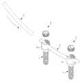
- the rod 2After inserting and fixing the vertebral fixation screw 1 into the vertebral bones of the damaged disc upper and lower portions as shown in FIG. 1, the rod 2 is connected to the vertebral fixation screw 1 to secure the distance between the vertebral bones. A method of fusion is normally performed.
- the rod 2may be fixed by a fastening stopper 3 which is screwed with the head portion 1a in a state of passing through the head portion 1a of the spinal fixation screw 1 as shown in FIG. 1. have.
- FIGS. 2 and 3are perspective views showing an example of a conventional spinal fixation minimally invasive surgical device.
- a conventional minimally invasive surgical device for spinal fixationis a support frame 11, two screw insertion tube 12 and one end portion 13a into which the spinal fixation screw 1 is inserted.
- (2)may include a rod inserter 13 to which it is coupled.
- the screw insertion tube 12is supported by the support frame 11. Specifically, the screw insertion tube 12 is coupled to the support frame 11 through the coupling block 14, the first adjustment screw 14a and the second adjustment screw 14b as shown in Figs. do. At this time, the screw insertion tube 12 is fixed by the first adjusting screw 14a in a state in which the coupling rod 12a formed at the upper end thereof is inserted and coupled, and the coupling block 14 passes through the support frame 11. Is fixed with respect to the support frame 11 by a second adjusting screw 14a.
- the screw insertion tube 12can be adjusted in an angle within a predetermined range by loosening and retightening the first adjusting screw 14a, and unwinding and retightening the second adjusting screw 14b.
- the positioncan be adjusted along the longitudinal direction of the support frame 11 through this.
- the rod through groove 12b through which the rod 2 is formedis formed. do.
- the operatorinserts the screw insertion tube 12 and inserts the screw insertion tube 12 into the screw insertion tube 12 through the screw insertion tube 12.
- the rod inserter 13is connected to the support frame 11 via the rotating arm 15 as shown in FIGS. 2 and 3. That is, the rod inserter 13 is provided to be rotatable with respect to the support frame 11 along a predetermined trajectory.
- the rod inserter 13allows the operator to apply the force directly by hand to move the rod inserter 13 along a predetermined trajectory (moving from the position of FIG. 2 to the position of FIG. 3), thereby loading the rod inserter 13.
- the rod 2 coupled to one end of the c)may be positioned in the rod through groove 12b of the screw insertion tube 12 to be fastened to the head portion 1a of the spinal fixation screw 1.
- FIG. 4 and 5are views for explaining the problem of the minimally invasive surgical apparatus of FIG.
- the rod 2is moved along the trajectory having a constant curvature by the rod inserter 13, the rod 2 is attached to the head portion 1a of the spinal fixation screw 1 in the actual procedure.
- the shapemay be as shown in FIG. 4, that is, the right end of the rod 2 may be lifted above the head portion 1a.
- the right end of the rod 2 lifted using a separate tool or toolis used.
- the left end of the rod 2may be lifted above the head portion 1a as shown in FIG. 5, which ultimately impairs the convenience and safety of the procedure. .
- An object of the present inventionis to provide a minimally invasive surgical device for spinal fixation that can prevent the rod located in the rod seating groove of the spinal fixation screw to be separated from the rod seating groove during the procedure to improve the convenience and safety of the procedure. .
- the spinal fixing screwhaving a head portion formed with a rod seating groove; Two or more screw insertion tubes for guiding the spinal fixation screw to the spinal bone of the patient; And a sleeve accommodated in at least one of the at least one screw insertion tube and covering at least a portion of an open upper side of the rod seating groove so that the rod positioned in the rod seating groove does not leave the rod seating groove. It is achieved by a minimally invasive surgical device for spinal fixation comprising a sleeve tube having a.
- the sleeveextends inward from the lower end of the side wall of the sleeve tube to cover the edge region of the rod seating groove.
- the sleeveis formed of an annular step bent extending from the lower end of the side wall of the sleeve tube, the head portion may be coupled to the screw body portion to enable position adjustment with respect to the screw body portion of the spinal fixation screw.
- the sleeve tubemay be accommodated in a screw insertion tube to which the rod first approaches one of the two or more screw insertion tubes.
- the minimally invasive surgical device for spinal fixationmay further include a position fixing means for positioning the sleeve tube with respect to the screw insertion tube while the sleeve tube is accommodated inside the screw insertion tube.
- the position fixing meansmay include a fixing protrusion protruding outward from the side wall of the sleeve tube; And a fixing groove formed in a side wall of the screw insertion tube to engage with the fixing protrusion to fix the sleeve tube.
- the spinal fixing screwhaving a head portion formed with a rod seating groove; And two or more screw insertion pipes for guiding the spinal fixation screw to the vertebral bone of the patient, wherein the head portion includes an opening of the rod seating groove so that the rod located in the rod seating groove is not separated from the rod seating groove. It is also achieved by a minimally invasive surgical device for spinal fixation, characterized in that a sleeve is provided covering at least a portion of the upper side.
- the sleeveextends inward from an upper end of the side wall of the head to cover an edge region of the rod seating groove.
- the sleevemay be formed as a step extending from the upper end of the side wall of the head portion, the head portion may be coupled to the screw body portion to enable position adjustment with respect to the screw body portion of the spinal screw.
- the minimally invasive surgical device for spinal fixationincludes a fastening stopper for fastening the rod located in the rod seating groove in combination with the spinal fixation screw, wherein the fastening stopper includes a fastening part for screwing the sleeve; And a protrusion extending downward from the fastening part to contact and pressurize the rod.
- the protrusionmay have a smaller diameter than the fastening portion.
- the present inventionby having a configuration to prevent the rod located in the rod seating groove of the spinal fixing screw is separated from the rod seating groove during the procedure, the rod located in the rod seating groove of the spinal screw fixing over the rod seating groove during the procedure.
- 1is a perspective view for explaining the coupling relationship of the spinal fixing screw, rod and fastening stopper.
- Figure 2is a perspective view showing an example of a conventional spinal fixation minimally invasive surgical device.
- Figure 3is a perspective view for explaining the movement of the rod inserter in the minimally invasive surgical apparatus of FIG.
- FIG. 4 and 5are views for explaining the problem of the minimally invasive surgical apparatus of FIG.
- Figure 6is a perspective view for explaining the minimally invasive surgical device for spinal fixation according to an embodiment of the present invention.
- FIG. 7is a view illustrating a state in which a sleeve tube is coupled to a screw insertion tube in the minimally invasive surgical device for spinal fixation of FIG. 6.
- FIG. 8is a schematic partial cross-sectional view for explaining the sleeve tube shown in FIG. 7.
- Figure 9is a perspective view for explaining a spinal fixation minimally invasive surgical apparatus according to another embodiment of the present invention.
- FIG. 10is a schematic partial cross-sectional view for explaining a sleeve provided in the spinal column fixing screw of FIG.
- FIG. 11is a schematic partial cross-sectional view illustrating a state in which a fastening stopper is fastened to the spinal fixation screw in FIG. 10.
- Figure 6is a perspective view for explaining a minimally invasive surgical device for spinal fixation according to an embodiment of the present invention
- Figure 7is a state in which the sleeve tube is coupled to the screw insertion tube in the minimally invasive surgical device for spinal fixation of FIG.
- FIG. 8is a schematic partial cross-sectional view for explaining the sleeve tube shown in FIG. 7.
- the minimally invasive surgical device 100 for spinal fixationincludes a spinal fixation screw 110, a screw insertion tube 120, a sleeve tube 130, and a fastening stopper 140. ) May be included.
- the minimally invasive surgical device 100 for spinal fixationmay further include a rod inserter (not shown).
- the rod inserter(not shown) is a means for moving the rod R to the position of the spinal fixation screw 110 by inserting the rod R through the soft tissue of the patient. Any one of a variety of known configurations can be selected, including the configuration of the rod inserter 13 disclosed in the invasive surgical device 10 (see FIGS. 2 and 3).
- Spinal fixing screw 110is fixed to the vertebral bones of the upper and lower parts of the damaged disk, as shown in Figure 6 and 8, the outer peripheral surface to be fastened to the head portion 111 and the spinal bone formed with the rod seating groove 113 It may include a screw body portion 112 is formed in the thread.
- the rod seating groove 113has a structure in which the upper side is open. Accordingly, the rod R inserted through the soft tissue of the patient by a rod inserter (not shown) is screwed with the head 111 in a state seated on the head 111 of the spinal screw 110.
- the fastening stopper 140may be fixed to the spinal fixation screw 110 by. At this time, the fastening stopper 140 is to be screwed with the head 111 of the spinal fixing screw 110, the inner peripheral surface of the head 111 and the outer peripheral surface of the fastening stopper 140 may be formed with a corresponding thread Can be.
- the head portion 111 of the spinal fixing screw 110has a structure that is integrally formed with the screw body portion 112, otherwise the head portion 111 May be coupled to the screw body 112 to enable position adjustment with respect to the screw body 112.
- the head 111may be separately manufactured and then coupled to the screw body 112 by a hinge method such as to move within a 15 ° range with respect to the screw body 112.
- the head portion 111 of the spinal fixation screw 110is positioned substantially perpendicular to the rod R by adjusting the position of the screw body portion 112 according to the insertion direction of the rod R. Since the rod (R) can be fastened to, the rod (R) after fastening is not only firmly fixed but also to receive a large force.
- the screw insertion tube 120provides a conduit for transporting the spinal fixation screw 110 to the position adjacent to the vertebral bone inside the skin from the outside of the patient's skin.
- Screw insertion tube 120is a spinal fixing screw 110 is usually inserted through the upper end.
- the head 111 of the inserted spinal fixing screw 110is located, and a rod through groove 125 through which the rod R penetrates is formed.
- the spinal fixation screwBy inserting 110, the spinal fixation screw 110 may be fastened to the vertebral bone using a tool such as an electric screwdriver.
- the fastening stopper 140 to the head 111 of the spinal fixing screw 110is also made through the screw insertion pipe (120).
- the screw insertion pipe 120is provided in two in this embodiment, the number of the screw insertion pipe 120 may be appropriately changed to two or more.
- the screw insertion tube 120may be supported by the support frame 150 as shown in FIGS. 6 and 7.
- the support frame 150is long in the horizontal direction intersecting the screw insertion tube 120 in a bar shape in which the groove 151 is formed along the longitudinal direction.
- the screw insertion tube 120is coupled to the support frame 150 through the coupling block 155, the first adjustment screw 155a and the second adjustment screw 155b as shown in Figs. Can be.
- the minimally invasive surgical device 100 for spinal fixationincludes a support frame 150 for supporting the screw insertion tube 120 and a coupling block as a means for coupling the screw insertion tube 120 to the support frame 150.
- the first adjusting screw 155a and the second adjusting screw 155bmay be further included.
- the screw insertion tube 120is fixed by the first adjusting screw 155a in a state where the upper end is coupled to the coupling block 155, the coupling block 155 is in a state that the support frame 150 penetrates It is fixed with respect to the support frame 150 by the 2nd adjustment screw 155b. Due to this coupling structure, the screw insertion tube 120 is capable of adjusting the angle within a predetermined range by loosening and retightening the first adjusting screw 155a, and unwinding and retightening the second adjusting screw 155b. Through this, position adjustment is possible along the longitudinal direction of the support frame 150.
- the coupling structure of the screw insertion tube 120 and the support frame 150is not limited to that disclosed in this embodiment can be variously changed.
- the sleeve tube 130may be inserted through the upper end of the screw insertion tube 120 and accommodated in the screw insertion tube 120.
- the sleeve tube 130is a screw insertion tube 120, as shown in Figure 8 so that the rod (R) located in the rod seating groove 113 is lifted up in the procedure so as not to be separated from the rod seating groove 113
- Itmay include a sleeve 135 to cover at least a portion of the open upper side of the rod seating groove 113 of the spinal fixing screw 110 in the state accommodated therein.
- the sleeve 135is preferably configured to extend inward from the lower end 131a of the side wall 131 of the sleeve tube 130 to cover the edge region of the rod seating groove 113 of the spinal fixation screw 110.
- the sleeve 135may be formed as an annular step bent extending from the lower end portion 131a of the side wall of the sleeve tube 130. This configuration of the sleeve 135 disclosed in this embodiment is fixed to the spine to fix the rod (R) with respect to the spinal fixing screw 110 even when the sleeve tube 130 is accommodated inside the screw insertion tube (120). This is to enable the operation of fastening the fastening stopper 140 to the head 111 of the screw 110.
- the screw insertion pipe 120provides a conduit for transporting the fastening stopper 140 as well as the spinal fixing screw 110.
- the edge region of the rod seating groove 113is provided.
- the sleeve 135 formed in the sleeve tube 130is not limited to the structure and shape disclosed in this embodiment may be appropriately changed. Furthermore, unlike the present embodiment in which the sleeve 135 is integrally formed with the side wall 131 of the sleeve tube 130, the sleeve 135 may be separately manufactured and then assembled with the side wall 131 of the sleeve tube 130. It may be.
- the sleeve tube 130is two screw insertion tube 120 to stably hold the position of the rod (R) without disturbing the transfer path of the rod (R) by a rod inserter (not shown) ),
- the rod Ris preferably accommodated in the screw insertion tube 120 which is approached first, ie, the screw insertion tube 120 disposed on the left side in FIGS. 6 and 7.
- the sleeve tube 130may be accommodated in the screw insertion tube 120 disposed on the right side in FIGS. 6 and 7, or may be further provided in both screw insertion tubes 120.
- Sleeve tube 130 having such a configurationcan prevent the rod (R) located in the rod seating groove 113 of the spinal fixing screw 110 is separated from the rod seating groove 113 during the procedure.
- the 'procedure process'is specifically inserted into the head (111) of the spinal fixing screw 110 by inserting the rod (R) fastening stopper 140 to the head 111 of the spinal fixing screw 110 By fastening) may mean a work up to fix the rod (R) for the spinal fixing screw (110).
- the minimally invasive surgical device 100 for spinal fixationhas a rod R positioned in the rod seating groove 113 of the spinal screw 110 lifted over the rod seating groove 113 during the procedure. It is possible to improve the convenience and safety of the procedure by ultimately solving the inconvenience of having to move it back to the position of the rod seating groove 113 and thereby causing damage to the soft tissue of the patient.
- the minimally invasive surgical device 100 for spinal fixationmay further include a position fixing means 160.
- the position fixing means 160is a means for positioning the sleeve tube 130 with respect to the screw insertion tube 120 while the sleeve tube 130 is accommodated in the screw insertion tube 120.
- the upper and lower positions of the sleeve tube 130may be fixed to the inside of the screw insertion tube 120 by). As such, the upper and lower positions of the sleeve tube 130 are fixed, so that the rod R lifting up the rod seating groove 113 can be stably prevented by the sleeve 135 of the sleeve tube 130.
- the position fixing means 160has a fixing protrusion 161 and protruding outwardly formed from the side wall 131 of the sleeve tube 130, as shown in Figure 6 and 7, the fixing protrusion 161 and It may be provided to the fixing groove 163 is formed in the side wall 121 of the screw insertion tube 120 to engage and position the sleeve tube 130.
- the fixing protrusion 161is formed in a pair of right and left on the side wall upper end portion 131b of the sleeve tube 130
- the fixing groove 163is a 'b' shape of the side wall 121 of the screw insertion tube 120. It can be formed in a pair on the left and right.
- the operatorinserts the sleeve tube 130 into the screw insertion tube 120 at the position where the fixing protrusion 161 corresponds to the fixing groove 163 without using a separate tool or tool.
- the simple operation of rotating the sleeve tube 130 at a predetermined anglemay fix the position of the sleeve tube 130 with respect to the screw insertion tube 120.
- the means for fixing the position of the sleeve tube 130is not limited to the position fixing means 160 disclosed in this embodiment can be changed to other various structures, of course.
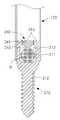
- FIG. 9is a perspective view illustrating a minimally invasive surgical device for spinal fixation according to another embodiment of the present invention
- FIG. 10is a schematic partial cross-sectional view for explaining a sleeve provided in the spinal fixation screw of FIG. 9,
- FIG. 10is a schematic partial cross-sectional view showing a state in which the fastening stopper is fastened to the spinal fixation screw.
- the minimally invasive surgical device 200 for spinal fixationmay include a spinal fixation screw 210, a screw insertion tube 120, and a fastening stopper 240.
- the minimally invasive surgical device 200 for spinal fixationmay further include a support frame 150, a coupling block 155, a first adjustment screw 155a, and a second adjustment screw 155b.
- Spinal fixing screw 210as shown in the above-described embodiment as shown in Figure 9 includes a head portion 211 and a screw body portion 212 is formed on the outer peripheral surface to be fastened to the vertebral bone, head portion 211 ) May have a rod seating groove 213 having an open top structure.
- the head portion 211 of the spinal fixing screw 210has a structure formed integrally with the screw body portion 212, otherwise the head portion 211 May be coupled to the screw body portion 212 to allow position adjustment with respect to the screw body portion 212.
- the head portion 211is opened in the rod seating groove 213 so that the rod (R) located in the rod seating groove 213 is not separated from the rod seating groove 213 as shown in FIGS. 9 and 10.
- a sleeve 215may be provided to cover at least a portion of the upper portion.
- the sleeve 215 of the present embodimentmay be provided as part of the spinal fixation screw 210, unlike the above-described embodiment provided in the form of a separate sleeve tube.
- the sleeve 215is preferably configured to extend inward from the upper end of the side wall of the head portion 211 to cover the edge region of the rod seating groove 213.
- the sleeve 215may be formed as a step extending from the upper end of the side wall of the head 211.
- the configuration of the sleeve 215 disclosed in the present embodimentprevents the rod R located in the rod seating groove 213 from being lifted over the rod seating groove 213 during the procedure, while the rod R is lifted. In order to be able to work to fasten the fastening stopper 240 to the spinal fixing screw 210 to fix the spinal fixing screw (210).
- the sleeve 215is configured to cover or cover the central area of the rod seating groove 213, the rod R located in the rod seating groove 213 is released from the rod seating groove 213. This can be prevented because it is difficult to fasten the fastening stopper 240 to the spinal fixation screw 210.
- the sleeve 215is provided on the spinal fixing screw 210 is not limited to the structure and shape disclosed in this embodiment can be changed appropriately. Further, unlike the present embodiment in which the sleeve 215 is integrally formed with the head portion 211, the sleeve 215 may be provided in a structure that is separately manufactured and then assembled with the head portion 211.
- Fastening stopper 240is for fixing the rod (R) located in the rod seating groove 213 in combination with the head portion 211 of the spinal fixing screw 210, as in the above-described embodiment, but in the present embodiment Since the sleeve 215 is provided in the head portion 211 of the fixing screw 210, it is necessary to have a structure and shape different from the fastening stopper 140 of the above-described embodiment.
- the fastening stopper 240is fastened to the fastening portion 241 and the fastening portion 241 is screwed with the sleeve 215 provided in the spinal fixing screw 210, as shown in Figure 9 and 11, the downward direction in the fastening portion 241 It may include a protruding portion 243 extending in contact to press the rod (R).
- threadsare formed on the inner circumferential surface of the sleeve 215 and the outer circumferential surface of the fastening portion 241, and the protrusion 243 has a smaller diameter than the fastening portion 241 so as to pass through the sleeve 215. .
- the fastening stopper 240may stably fix the rod R with respect to the spinal fixation screw 210 provided with the sleeve 215.
- the minimally invasive surgical device 200 for spinal fixationhas a sleeve 215 covering at least a portion of the open upper side of the rod seating groove 213 at the head portion 211 of the spinal fixation screw 210. ), The rod (R) located in the rod seating groove 213 of the spinal fixation screw 210 is lifted over the rod seating groove 213 during the procedure, and moved to the position of the rod seating groove 213 again.
- the present inventioncan be used in the spinal fixation surgical apparatus used in the minimally invasive surgery (Minimally Invasive Surgery).
Landscapes
- Health & Medical Sciences (AREA)
- Orthopedic Medicine & Surgery (AREA)
- Life Sciences & Earth Sciences (AREA)
- Neurology (AREA)
- Surgery (AREA)
- Heart & Thoracic Surgery (AREA)
- Engineering & Computer Science (AREA)
- Biomedical Technology (AREA)
- Nuclear Medicine, Radiotherapy & Molecular Imaging (AREA)
- Medical Informatics (AREA)
- Molecular Biology (AREA)
- Animal Behavior & Ethology (AREA)
- General Health & Medical Sciences (AREA)
- Public Health (AREA)
- Veterinary Medicine (AREA)
- Surgical Instruments (AREA)
Abstract
Description
Translated fromKorean본 발명은 척추 고정용 시술장치에 관한 것으로, 더 상세하게는 최소침습수술(Minimally Invasive Surgery)에 사용되는 척추 고정용 시술장치에 관한 것이다.The present invention relates to a spinal stabilization apparatus, and more particularly to a spinal stabilization apparatus used for minimally invasive surgery (Minimally Invasive Surgery).
일반적으로 사람의 척추는 다수의 척추 뼈와 각각의 척추 뼈 사이에서 완충작용을 하는 디스크 등으로 구성되어 있다. 이러한 척추는 사람이 자세를 유지할 수 있게 도와줄 뿐만 아니라, 운동의 토대가 되며 내장 기관을 보호하는 중요한 역할을 하고 있다.In general, a human spine is composed of a plurality of vertebral bones and a disk that cushions between each vertebral bone. These vertebrae not only help a person maintain his posture, but also form the basis of his movements and play an important role in protecting internal organs.
그러나 비정상적인 자세가 오랫동안 유지되거나 노화에 따른 퇴행성 질환 또는 외부로부터 충격을 받게 되면 척추 뼈 마디의 디스크가 손상되어 척추 디스크 질환이 발생할 수 있는데, 이러한 척추 디스크 질환은 척추 뼈 마디를 통해 인체의 각 부분에 연결되는 신경이 압박되어 통증을 유발하게 된다.However, if an abnormal posture is maintained for a long time, or a degenerative disease caused by aging or an external shock, the disk of the spinal bone node may be damaged and the spinal disc disease may be caused. The connecting nerves are compressed, causing pain.
따라서, 척추 디스크 환자는 척추 뼈의 손상된 부분이 눌리거나 압박되지 않도록 손상된 부위의 디스크를 제거하고, 금속 또는 플라스틱 재질로 이루어진 인공 보조물(케이지)에 뼈 조각을 채워 디스크를 제거한 부위에 삽입한 다음, 도 1에 도시된 바와 같이 손상된 디스크 상하부위의 척추 뼈에 척추고정스크류(1)를 삽입·고정한 후, 척추고정스크류(1)에 로드(2)를 연결하여 척추 뼈 사이의 거리를 확보함으로써 골 융합(fusion)이 정상적으로 이루어지도록 하는 방식이 시술되고 있다. 이때, 로드(2)는 도 1에 도시된 바와 같이 척추고정스크류(1)의 헤드부(1a)를 관통한 상태에서 헤드부(1a)와 나사 결합되는 체결 마개(3)에 의해 고정될 수 있다.Therefore, the patient with the spinal disc removes the disc from the damaged part so that the damaged part of the vertebral bone is not pressed or pressed, and fills the disc with the bone fragment filled with an artificial support (cage) made of metal or plastic material. After inserting and fixing the
그런데, 이러한 척추 수술은 척추고정스크류(1)를 척추 뼈에 체결한 다음 로드(2)를 척추고정스크류(1)에 체결하기 위해 먼저 손상된 척추부위의 피부를 일정크기 이상으로 절개하는 작업이 필수적으로 요구되므로, 침습 부위가 커서 환자의 회복을 지연시키고 상처로 인한 수술만족도가 낮다는 문제점이 있다.However, in such spinal surgery, it is essential to cut the skin of the damaged vertebral portion more than a certain size in order to fasten the spinal fixation screw (1) to the vertebral bone and then fasten the rod (2) to the spinal fixation screw (1). As it is required, there is a problem in that the invasive area is large, delaying the recovery of the patient and low surgical satisfaction due to the wound.
이에, 최근에는 척추 수술 시 침습 부위를 최소화할 수 있는 최소침습수술(Minimally Invasive Surgery) 기법들이 개발되어 적용되고 있다.Therefore, recently, minimally invasive surgery (Minimally Invasive Surgery) techniques that can minimize the invasive area during spinal surgery has been developed and applied.
도 2 및 도 3은 종래의 척추 고정용 최소침습 시술장치의 일 예를 나타내는 사시도들이다.2 and 3 are perspective views showing an example of a conventional spinal fixation minimally invasive surgical device.
도 2 및 도 3을 참조하면, 종래의 척추 고정용 최소침습 시술장치는 지지 프레임(11), 척추고정스크류(1)가 삽입되는 두 개의 스크류 삽입관(12) 및 일단부(13a)에 로드(2)가 결합되는 로드 삽입기(13)를 포함할 수 있다.2 and 3, a conventional minimally invasive surgical device for spinal fixation is a
스크류 삽입관(12)은 지지 프레임(11)에 의해 지지된다. 구체적으로, 스크류 삽입관(12)은 도 2 및 도 3에 도시된 바와 같이 결합 블록(14), 제1 조정나사(14a) 및 제2 조정나사(14b)를 통해 지지 프레임(11)에 결합된다. 이때 스크류 삽입관(12)은 그 상단부에 형성된 결합봉(12a)이 삽입 결합된 상태에서 제1 조정나사(14a)에 의해 고정되고, 결합 블록(14)은 지지 프레임(11)이 관통한 상태에서 제2 조정나사(14a)에 의해 지지 프레임(11)에 대해 고정된다. 이러한 결합 구조에 의해, 스크류 삽입관(12)은 제1 조정나사(14a)를 풀고 다시 조이는 과정을 통해 일정 범위 내에서 각도 조절이 가능하고, 제2 조정나사(14b)를 풀고 다시 조이는 과정을 통해 지지 프레임(11)의 길이 방향을 따라 위치 조정이 가능해진다. 한편, 스크류 삽입관(12)의 후단부에는 도 3에 도시된 바와 같이 삽입된 척추고정스크류(1)의 헤드부(1a)가 위치하고 로드(2)가 관통하는 로드 관통홈(12b)이 형성된다. 이러한 스크류 삽입관(12)을 통해 시술자는 환자의 피부를 절개하는 대신에 환자의 피부에 최소한의 구멍을 내고 스크류 삽입관(12)을 꽂은 다음, 스크류 삽입관(12)에 척추고정스크류(1)를 삽입하여 전동 드라이버 등의 공구를 사용하여 척추고정스크류(1)를 척추 뼈에 체결할 수 있다. 또한, 로드(2)를 척추고정스크류(110)에 대해 고정시키기 위해 척추고정스크류(1)의 헤드부(1a)에 체결 마개(3)를 체결하는 작업도 스크류 삽입관(12)을 통해 이루어질 수 있다.The
로드 삽입기(13)는 도 2 및 도 3에 도시된 바와 같이 회전 아암(15)을 통해 지지 프레임(11)에 연결된다. 즉, 로드 삽입기(13)는 지지 프레임(11)에 대해 소정의 궤적을 따라 회전 이동 가능하게 마련된다. 이러한 로드 삽입기(13)를 통해 시술자는 손으로 직접 힘을 가해서 로드 삽입기(13)를 소정의 궤적을 따라 이동시킴으로써(도 2의 위치에서 도 3의 위치로 이동), 로드 삽입기(13)의 일단부에 결합된 로드(2)를 스크류 삽입관(12)의 로드 관통홈(12b)에 위치시켜 척추고정스크류(1)의 헤드부(1a)와 체결할 수 있다.The
도 4 및 도 5는 도 2의 최소침습 시술장치의 문제점을 설명하기 위한 도면들이다.4 and 5 are views for explaining the problem of the minimally invasive surgical apparatus of FIG.
앞서 설명한 바와 같이 로드(2)는 로드 삽입기(13)에 의해 일정한 곡률을 갖는 궤적을 따라 이동하기 때문에, 실제 시술에 있어서 로드(2)가 척추고정스크류(1)의 헤드부(1a)에 처음 위치하였을 때 모습은 도 4에 도시된 바와 같을 수 있다, 즉, 로드(2)의 우측 단부는 헤드부(1a) 위쪽으로 들어 올려진 상태가 될 수 있다.As described above, since the
따라서, 도 4에서 우측에 배치된 척추고정스크류(1)의 헤드부(1a)에 체결 마개(3)를 체결하기 위해서는 별도의 도구나 공구를 사용하여 들어 올려진 로드(2)의 우측 단부를 아래로 눌러주어야 하는데, 이때 로드(2)의 좌측 단부는 도 5에 도시된 바와 같이 헤드부(1a) 위로 들어 올려질 우려가 있으며, 이는 궁극적으로 시술의 편의성 및 안전성을 저해하는 요소가 되고 있다.Therefore, in order to fasten the
본 발명의 목적은, 척추고정스크류의 로드 안착홈에 위치한 로드가 시술 과정에서 로드 안착홈에서 이탈되는 것을 방지하여 시술의 편의성 및 안전성을 향상시킬 수 있는 척추 고정용 최소침습 시술장치를 제공하는 것이다.An object of the present invention is to provide a minimally invasive surgical device for spinal fixation that can prevent the rod located in the rod seating groove of the spinal fixation screw to be separated from the rod seating groove during the procedure to improve the convenience and safety of the procedure. .
상기 목적은, 본 발명에 따라, 로드 안착홈이 형성된 헤드부를 갖는 척추고정스크류; 상기 척추고정스크류를 환자의 척추 뼈로 안내하기 위한 둘 이상의 스크류 삽입관; 및 상기 둘 이상의 스크류 삽입관 중 적어도 하나의 스크류 삽입관 내부에 수용되고, 상기 로드 안착홈에 위치한 로드가 상기 로드 안착홈에서 이탈되지 않도록 상기 로드 안착홈의 개방된 상측의 적어도 일부 영역을 덮는 슬리브를 갖는 슬리브 관을 포함하는 척추 고정용 최소침습 시술장치에 의해 달성된다.The object is, according to the present invention, the spinal fixing screw having a head portion formed with a rod seating groove; Two or more screw insertion tubes for guiding the spinal fixation screw to the spinal bone of the patient; And a sleeve accommodated in at least one of the at least one screw insertion tube and covering at least a portion of an open upper side of the rod seating groove so that the rod positioned in the rod seating groove does not leave the rod seating groove. It is achieved by a minimally invasive surgical device for spinal fixation comprising a sleeve tube having a.
상기 슬리브는, 상기 슬리브 관의 측벽 하단부에서 내측 방향으로 연장되어 상기 로드 안착홈의 가장자리 영역을 덮는 것이 바람직하다.Preferably, the sleeve extends inward from the lower end of the side wall of the sleeve tube to cover the edge region of the rod seating groove.
상기 슬리브는, 상기 슬리브 관의 측벽 하단부에서 절곡 연장되는 환형 단턱으로 형성되고, 상기 헤드부는, 상기 척추고정스크류의 나사 몸체부에 대해 위치 조정이 가능하도록 상기 나사 몸체부에 결합될 수 있다.The sleeve is formed of an annular step bent extending from the lower end of the side wall of the sleeve tube, the head portion may be coupled to the screw body portion to enable position adjustment with respect to the screw body portion of the spinal fixation screw.
상기 슬리브 관은, 상기 둘 이상의 스크류 삽입관 중 상기 로드가 가장 먼저 접근하는 스크류 삽입관에 수용될 수 있다.The sleeve tube may be accommodated in a screw insertion tube to which the rod first approaches one of the two or more screw insertion tubes.
상기 척추 고정용 최소침습 시술장치는, 상기 슬리브 관이 상기 스크류 삽입관 내부에 수용된 상태에서 상기 스크류 삽입관에 대해 상기 슬리브 관을 위치 고정하기 위한 위치고정수단을 더 포함할 수 있다.The minimally invasive surgical device for spinal fixation may further include a position fixing means for positioning the sleeve tube with respect to the screw insertion tube while the sleeve tube is accommodated inside the screw insertion tube.
상기 위치고정수단은, 상기 슬리브 관의 측벽에서 외측 방향으로 돌출 형성되는 고정 돌기부; 및 상기 고정 돌기부와 맞물려서 상기 슬리브 관을 위치 고정하도록 상기 스크류 삽입관의 측벽에 형성되는 고정 홈부를 포함할 수 있다.The position fixing means may include a fixing protrusion protruding outward from the side wall of the sleeve tube; And a fixing groove formed in a side wall of the screw insertion tube to engage with the fixing protrusion to fix the sleeve tube.
상기 목적은, 본 발명에 따라, 로드 안착홈이 형성된 헤드부를 갖는 척추고정스크류; 및 상기 척추고정스크류를 환자의 척추 뼈로 안내하기 위한 둘 이상의 스크류 삽입관을 포함하고, 상기 헤드부에는, 상기 로드 안착홈에 위치한 로드가 상기 로드 안착홈에서 이탈되지 않도록 상기 로드 안착홈의 개방된 상측의 적어도 일부 영역을 덮는 슬리브가 마련되는 것을 특징으로 하는 척추 고정용 최소침습 시술장치에 의해서도 달성된다.The object is, according to the present invention, the spinal fixing screw having a head portion formed with a rod seating groove; And two or more screw insertion pipes for guiding the spinal fixation screw to the vertebral bone of the patient, wherein the head portion includes an opening of the rod seating groove so that the rod located in the rod seating groove is not separated from the rod seating groove. It is also achieved by a minimally invasive surgical device for spinal fixation, characterized in that a sleeve is provided covering at least a portion of the upper side.
상기 슬리브는, 상기 헤드부의 측벽 상단부에서 내측 방향으로 연장되어 상기 로드 안착홈의 가장자리 영역을 덮는 것이 바람직하다.Preferably, the sleeve extends inward from an upper end of the side wall of the head to cover an edge region of the rod seating groove.
상기 슬리브는, 상기 헤드부의 측벽 상단부에서 절곡 연장되는 단턱으로 형성되고, 상기 헤드부는, 상기 척추고정스크류의 나사 몸체부에 대해 위치 조정이 가능하도록 상기 나사 몸체부에 결합될 수 있다.The sleeve may be formed as a step extending from the upper end of the side wall of the head portion, the head portion may be coupled to the screw body portion to enable position adjustment with respect to the screw body portion of the spinal screw.
상기 척추 고정용 최소침습 시술장치는, 상기 척추고정스크류와 결합하여 상기 로드 안착홈에 위치한 상기 로드를 고정하기 위한 체결 마개를 더 포함하고, 상기 체결 마개는, 상기 슬리브와 나사 결합하는 체결부; 및 상기 체결부에서 하측 방향으로 연장되어 상기 로드를 접촉 가압하는 돌출부를 포함할 수 있다. 이때, 상기 돌출부는, 상기 체결부보다 작은 지름을 가질 수 있다.The minimally invasive surgical device for spinal fixation includes a fastening stopper for fastening the rod located in the rod seating groove in combination with the spinal fixation screw, wherein the fastening stopper includes a fastening part for screwing the sleeve; And a protrusion extending downward from the fastening part to contact and pressurize the rod. In this case, the protrusion may have a smaller diameter than the fastening portion.
본 발명은, 척추고정스크류의 로드 안착홈에 위치한 로드가 시술 과정에서 로드 안착홈에서 이탈되는 것을 방지하기 구성을 구비함으로써, 척추고정스크류의 로드 안착홈에 위치한 로드가 시술 과정 중에 로드 안착홈 위로 들어 올려져서 이를 다시 로드 안착홈의 위치로 이동시켜야 하는 불편함과 이로 인해 환자의 연부 조직 등이 손상되는 문제점을 해결하여 궁극적으로 시술의 편의성 및 안전성을 향상시킬 수 있다.The present invention, by having a configuration to prevent the rod located in the rod seating groove of the spinal fixing screw is separated from the rod seating groove during the procedure, the rod located in the rod seating groove of the spinal screw fixing over the rod seating groove during the procedure The inconvenience of having to lift and move it back to the position of the rod seating groove, thereby solving the problem of damage to the soft tissue of the patient, can ultimately improve the convenience and safety of the procedure.
도 1은 척추고정스크류, 로드 및 체결 마개의 결합 관계를 설명하기 위한 사시도이다.1 is a perspective view for explaining the coupling relationship of the spinal fixing screw, rod and fastening stopper.
도 2는 종래의 척추 고정용 최소침습 시술장치의 일 예를 나타내는 사시도이다.Figure 2 is a perspective view showing an example of a conventional spinal fixation minimally invasive surgical device.
도 3은 도 2의 최소침습 시술장치에서 로드 삽입기의 이동을 설명하기 위한 사시도이다.Figure 3 is a perspective view for explaining the movement of the rod inserter in the minimally invasive surgical apparatus of FIG.
도 4 및 도 5는 도 2의 최소침습 시술장치의 문제점을 설명하기 위한 도면들이다.4 and 5 are views for explaining the problem of the minimally invasive surgical apparatus of FIG.
도 6은 본 발명의 일 실시예에 따른 척추 고정용 최소침습 시술장치를 설명하기 위한 사시도이다.Figure 6 is a perspective view for explaining the minimally invasive surgical device for spinal fixation according to an embodiment of the present invention.
도 7은 도 6의 척추 고정용 최소침습 시술장치에서 스크류 삽입관에 슬리브 관이 결합된 상태를 도시한 도면이다.FIG. 7 is a view illustrating a state in which a sleeve tube is coupled to a screw insertion tube in the minimally invasive surgical device for spinal fixation of FIG. 6.
도 8은 도 7에 도시된 슬리브 관을 설명하기 위한 개략적인 부분 단면도이다.FIG. 8 is a schematic partial cross-sectional view for explaining the sleeve tube shown in FIG. 7.
도 9는 본 발명의 다른 실시예에 따른 척추 고정용 최소침습 시술장치를 설명하기 위한 사시도이다.Figure 9 is a perspective view for explaining a spinal fixation minimally invasive surgical apparatus according to another embodiment of the present invention.
도 10은 도 9의 척추고정스크류에 마련된 슬리브를 설명하기 위한 개략적인 부분 단면도이다.10 is a schematic partial cross-sectional view for explaining a sleeve provided in the spinal column fixing screw of FIG.
도 11은 도 10에서 척추고정스크류에 체결 마개가 체결된 상태를 도시한 개략적인 부분 단면도이다.FIG. 11 is a schematic partial cross-sectional view illustrating a state in which a fastening stopper is fastened to the spinal fixation screw in FIG. 10.
본 발명과 본 발명의 동작상의 이점 및 본 발명의 실시에 의하여 달성되는 목적을 충분히 이해하기 위해서는 본 발명의 바람직한 실시예를 예시하는 첨부 도면 및 첨부 도면에 기재된 내용을 참조하여야만 한다.In order to fully understand the present invention, the operational advantages of the present invention, and the objects achieved by the practice of the present invention, reference should be made to the accompanying drawings which illustrate preferred embodiments of the present invention and the contents described in the accompanying drawings.
이하, 첨부된 도면을 참조하여 본 발명의 바람직한 실시예를 설명함으로써, 본 발명을 상세히 설명한다. 다만, 본 발명을 설명함에 있어서 이미 공지된 기능 혹은 구성에 대한 설명은, 본 발명의 요지를 명료하게 하기 위하여 생략하기로 한다.Hereinafter, exemplary embodiments of the present invention will be described in detail with reference to the accompanying drawings. However, in describing the present invention, descriptions of functions or configurations already known will be omitted to clarify the gist of the present invention.
도 6은 본 발명의 일 실시예에 따른 척추 고정용 최소침습 시술장치를 설명하기 위한 사시도이고, 도 7은 도 6의 척추 고정용 최소침습 시술장치에서 스크류 삽입관에 슬리브 관이 결합된 상태를 도시한 도면이며, 도 8은 도 7에 도시된 슬리브 관을 설명하기 위한 개략적인 부분 단면도이다.Figure 6 is a perspective view for explaining a minimally invasive surgical device for spinal fixation according to an embodiment of the present invention, Figure 7 is a state in which the sleeve tube is coupled to the screw insertion tube in the minimally invasive surgical device for spinal fixation of FIG. FIG. 8 is a schematic partial cross-sectional view for explaining the sleeve tube shown in FIG. 7.
도 6 내지 도 8을 참조하면, 본 실시예에 따른 척추 고정용 최소침습 시술장치(100)는, 척추고정스크류(110), 스크류 삽입관(120), 슬리브 관(130) 및 체결 마개(140)를 포함할 수 있다.6 to 8, the minimally invasive
또한, 첨부된 도면들에는 도시되지 않았지만, 척추 고정용 최소침습 시술장치(100)는 로드 삽입기(미도시)를 더 포함할 수 있다. 이러한 로드 삽입기(미도시)는 환자의 연부 조직을 뚫고 로드(R)를 삽입하여 척추고정스크류(110)의 위치로 로드(R)를 이동시키기 위한 수단으로, 앞서 설명한 종래의 척추 고정용 최소침습 시술장치(10, 도 2 및 도 3 참조)에서 개시된 로드 삽입기(13)의 구성을 포함하여 공지의 다양한 구성 중 어느 하나가 선택될 수 있다.In addition, although not shown in the accompanying drawings, the minimally invasive
척추고정스크류(110)는 손상된 디스크 상하부위의 척추 뼈에 체결 고정되는 것으로, 도 6 및 도 8에 도시된 바와 같이 로드 안착홈(113)이 형성된 헤드부(111)와 척추 뼈에 체결되도록 외주면에 나사산이 형성된 나사 몸체부(112)를 포함할 수 있다. 이때, 로드 안착홈(113)은 상측이 개방된 구조를 갖는다. 이에 따라, 로드 삽입기(미도시)에 의해 환자의 연부 조직을 뚫고 삽입되는 로드(R)는 척추고정스크류(110)의 헤드부(111)에 안착된 상태에서 헤드부(111)와 나사 결합하는 체결 마개(140)에 의해 척추고정스크류(110)에 대해 고정될 수 있다. 이때, 체결 마개(140)가 척추고정스크류(110)의 헤드부(111)와 나사 결합할 수 있도록, 헤드부(111)의 내주면과 체결 마개(140)의 외주면에는 서로 대응하는 나사산이 형성될 수 있다.Spinal fixing
한편, 첨부된 도면들에 도시된 바와 같이 본 실시예에서 척추고정스크류(110)의 헤드부(111)는 나사 몸체부(112)와 일체로 형성되는 구조를 갖지만, 이와 다르게 헤드부(111)는 나사 몸체부(112)에 대해 위치 조정이 가능하도록 나사 몸체부(112)에 결합될 수 있다. 구체적으로, 헤드부(111)는 별도로 제작된 후 나사 몸체부(112)에 대해 예컨대 15°범위 내에서 움직일 수 있도록 힌지 방식 등에 의해 나사 몸체부(112)에 결합될 수 있다. 이에 따라, 척추고정스크류(110)의 헤드부(111)는 로드(R)의 삽입 방향에 따라 나사 몸체부(112)에 대한 위치를 조정하여 로드(R)에 대해 실질적으로 수직으로 배치된 상태에서 로드(R)와 체결될 수 있으므로, 체결 후 로드(R)는 견고히 고정될 뿐만 아니라 큰 힘을 받을 수 있게 된다.On the other hand, as shown in the accompanying drawings in the present embodiment, the
스크류 삽입관(120)은 환자의 피부 바깥쪽에서 피부 안쪽의 척추 뼈와 인접한 위치로 척추고정스크류(110)를 이송하기 위한 관로를 제공한다. 스크류 삽입관(120)은 통상 상단부를 통해 척추고정스크류(110)가 삽입된다. 스크류 삽입관(120)의 하단부에는 삽입된 척추고정스크류(110)의 헤드부(111)가 위치하고 로드(R)가 관통하는 로드 관통홈(125)이 형성된다. 이러한 스크류 삽입관(120)을 통해, 시술자는 환자의 피부를 절개하는 대신에 환자의 피부에 최소한의 구멍을 내고 스크류 삽입관(120)을 꽂은 다음, 스크류 삽입관(120)에 척추고정스크류(110)를 삽입하여 전동 드라이버 등의 공구를 사용하여 척추고정스크류(110)를 척추 뼈에 체결할 수 있다. 또한, 로드(R)를 척추고정스크류(110)에 대해 고정하기 위해 척추고정스크류(110)의 헤드부(111)에 체결 마개(140)를 체결하는 작업도 스크류 삽입관(120)을 통해 이루어질 수 있다. 한편, 스크류 삽입관(120)은 본 실시예에서 두 개로 마련되지만, 스크류 삽입관(120)의 개수는 둘 이상으로 적절히 변경될 수 있다.The
한편, 스크류 삽입관(120)은 도 6 및 도 7에 도시된 바와 같이 지지 프레임(150)에 의해 지지될 수 있다. 여기서, 지지 프레임(150)은 길이 방향을 따라 그루브(151)가 형성된 바(bar) 형상으로 스크류 삽입관(120)과 교차하는 가로 방향으로 길게 배치된다. 구체적으로, 스크류 삽입관(120)은 도 6 및 도 7에 도시된 바와 같이 결합 블록(155), 제1 조정나사(155a) 및 제2 조정나사(155b)를 통해 지지 프레임(150)에 결합될 수 있다. 다시 말해서, 척추 고정용 최소침습 시술장치(100)는 스크류 삽입관(120)을 지지하는 지지 프레임(150)과, 스크류 삽입관(120)을 지지 프레임(150)에 결합시키기 위한 수단으로 결합 블록(155), 제1 조정나사(155a) 및 제2 조정나사(155b)를 더 포함할 수 있다. 이때, 스크류 삽입관(120)은 그 상단부가 결합 블록(155)에 결합된 상태에서 제1 조정나사(155a)에 의해 고정되고, 결합 블록(155)은 지지 프레임(150)이 관통한 상태에서 제2 조정나사(155b)에 의해 지지 프레임(150)에 대해 고정된다. 이러한 결합 구조에 의해, 스크류 삽입관(120)은 제1 조정나사(155a)를 풀고 다시 조이는 과정을 통해 일정 범위 내에서 각도 조절이 가능하고, 제2 조정나사(155b)를 풀고 다시 조이는 과정을 통해 지지 프레임(150)의 길이 방향을 따라 위치 조정이 가능해진다. 다만, 스크류 삽입관(120)과 지지 프레임(150)의 결합 구조는 본 실시예에서 개시된 것에 한정되지 아니하고 다양하게 변경될 수 있다.Meanwhile, the
슬리브 관(130)은 도 6 및 도 7에 도시된 바와 같이 스크류 삽입관(120)의 상단부를 통해 삽입되어 스크류 삽입관(120) 내부에 수용될 수 있다. 그리고 슬리브 관(130)은 로드 안착홈(113)에 위치한 로드(R)가 시술 과정에 들어 올려져서 로드 안착홈(113)에서 이탈되지 않도록, 도 8에 도시된 바와 같이 스크류 삽입관(120) 내부에 수용된 상태에서 척추고정스크류(110)의 로드 안착홈(113)의 개방된 상측의 적어도 일부 영역을 덮는 슬리브(135)를 포함할 수 있다.6 and 7, the
이때, 슬리브(135)는 슬리브 관(130)의 측벽(131)의 하단부(131a)에서 내측 방향으로 연장되어 척추고정스크류(110)의 로드 안착홈(113)의 가장자리 영역을 덮도록 구성됨이 바람직하다. 예컨대, 슬리브(135)는 슬리브 관(130)의 측벽 하단부(131a)에서 절곡 연장되는 환형 단턱으로 형성될 수 있다. 본 실시예에서 개시하고 있는 이러한 슬리브(135)의 구성은 슬리브 관(130)이 스크류 삽입관(120) 내부에 수용된 상태에서도 로드(R)를 척추고정스크류(110)에 대해 고정하기 위해 척추고정스크류(110)의 헤드부(111)에 체결 마개(140)를 체결하는 작업이 가능하도록 하기 위함이다. 다시 말해서, 앞서 설명한 바와 같이 스크류 삽입관(120)은 척추고정스크류(110)뿐만 아니라 체결 마개(140)를 이송하기 위한 관로를 제공하는데, 본 실시예에서는 로드 안착홈(113)의 가장자리 영역만 덮도록 슬리브 관(130)의 측벽 하단부(131a)에 슬리브(135)를 형성함으로써, 슬리브 관(130)의 슬리브(135)가 체결 마개(140)의 이송 경로를 방해하지 않도록 하는 것이다.In this case, the
다만, 슬리브 관(130)에 형성되는 슬리브(135)는 본 실시예에서 개시된 구조 및 형상에 한정되지 아니하고 적절히 변경될 수 있음은 물론이다. 더 나아가, 슬리브(135)는 슬리브 관(130)의 측벽(131)과 일체로 형성되는 본 실시예와 다르게, 별도로 제작된 후 슬리브 관(130)의 측벽(131)과 조립되는 구조로 제공될 수도 있다.However, the
한편, 슬리브 관(130)은 로드 삽입기(미도시)에 의한 로드(R)의 이송 경로를 방해하지 않으면서 로드(R)의 위치를 안정적으로 잡아줄 수 있도록, 두 개의 스크류 삽입관(120) 중 로드(R)가 가장 먼저 접근하는 스크류 삽입관(120), 즉 도 6 및 도 7에서 좌측에 배치된 스크류 삽입관(120)에 수용되는 것이 바람직하다. 이와 다르게, 슬리브 관(130)은 도 6 및 도 7에서 우측에 배치된 스크류 삽입관(120)에 수용되거나, 더 나아가 두 개의 스크류 삽입관(120) 모두에 제공될 수도 있다.On the other hand, the
이러한 구성을 갖는 슬리브 관(130)은 척추고정스크류(110)의 로드 안착홈(113)에 위치한 로드(R)가 시술 과정에서 로드 안착홈(113)에서 이탈되는 것을 방지할 수 있다. 이때, '시술 과정'은 구체적으로 로드(R)를 삽입하여 척추고정스크류(110)의 헤드부(111)에 위치시킨 이후부터 척추고정스크류(110)의 헤드부(111)에 체결 마개(140)를 체결하여 척추고정스크류(110)에 대해 로드(R)를 고정시키는 작업까지를 의미할 수 있다.
이에 따라, 본 실시예에 따른 척추 고정용 최소침습 시술장치(100)는 척추고정스크류(110)의 로드 안착홈(113)에 위치한 로드(R)가 시술 과정 중에 로드 안착홈(113) 위로 들어 올려져서 이를 다시 로드 안착홈(113)의 위치로 이동시켜야 하는 불편함과 이로 인해 환자의 연부 조직 등이 손상되는 문제점을 해결하여 궁극적으로 시술의 편의성 및 안전성을 향상시킬 수 있다.Accordingly, the minimally invasive
도 6 및 도 7을 참조하면, 본 실시예에 따른 척추 고정용 최소침습 시술장치(100)는 위치고정수단(160)을 더 포함할 수 있다. 위치고정수단(160)은 슬리브 관(130)이 스크류 삽입관(120) 내부에 수용된 상태에서 스크류 삽입관(120)에 대해 슬리브 관(130)을 위치 고정하는 수단으로, 이러한 위치고정수단(160)에 의해 슬리브 관(130)은 스크류 삽입관(120)의 내부에서 그 상하 위치가 고정될 수 있다. 이처럼, 슬리브 관(130)의 상하 위치가 고정됨으로써, 로드 안착홈(113) 위로 들어 올려지는 로드(R)는 슬리브 관(130)의 슬리브(135)에 의해 안정적으로 저지될 수 있는 것이다.6 and 7, the minimally invasive
구체적으로, 위치고정수단(160)은 도 6 및 도 7에 도시된 바와 같이 슬리브 관(130)의 측벽(131)에서 외측 방향으로 돌출 형성되는 고정 돌기부(161)와, 고정 돌기부(161)와 맞물려서 슬리브 관(130)을 위치 고정하도록 스크류 삽입관(120)의 측벽(121)에 형성되는 고정 홈부(163)로 제공될 수 있다. 이때, 고정 돌기부(161)는 슬리브 관(130)의 측벽 상단부(131b)에 좌우 한 쌍으로 형성되고, 고정 홈부(163)는 'ㄴ'자 형상으로 스크류 삽입관(120)의 측벽(121)에 좌우 한 쌍으로 형성될 수 있다. 이러한 구성에 의해, 시술자는 별도의 도구나 공구를 사용하지 않고서도, 고정 돌기부(161)가 고정 홈부(163)와 대응하는 위치에서 스크류 삽입관(120)에 슬리브 관(130)을 집어넣은 후, 도 7에 도시된 바와 같이 슬리브 관(130)을 소정의 각도로 회전시키는 간단한 동작으로, 스크류 삽입관(120)에 대한 슬리브 관(130)의 위치를 고정할 수 있다. 다만, 본 발명에서 슬리브 관(130)의 위치를 고정하는 수단은 본 실시예에서 개시된 위치고정수단(160)에 한정되지 아니하고 다른 다양한 구조로 변경될 수 있음은 물론이다.Specifically, the position fixing means 160 has a fixing
이하, 도 9 내지 도 11을 참조하여 본 발명의 다른 실시예에 따른 척추 고정용 최소침습 시술장치를 전술한 실시예와 상이한 점을 중심으로 설명한다. Hereinafter, the minimally invasive surgical device for fixation of a spine according to another embodiment of the present invention will be described with reference to FIGS. 9 to 11.
도 9는 본 발명의 다른 실시예에 따른 척추 고정용 최소침습 시술장치를 설명하기 위한 사시도이고, 도 10은 도 9의 척추고정스크류에 마련된 슬리브를 설명하기 위한 개략적인 부분 단면도이며, 도 11은 도 10에서 척추고정스크류에 체결 마개가 체결된 상태를 도시한 개략적인 부분 단면도이다.FIG. 9 is a perspective view illustrating a minimally invasive surgical device for spinal fixation according to another embodiment of the present invention, FIG. 10 is a schematic partial cross-sectional view for explaining a sleeve provided in the spinal fixation screw of FIG. 9, and FIG. 10 is a schematic partial cross-sectional view showing a state in which the fastening stopper is fastened to the spinal fixation screw.
도 9 내지 도 11을 참조하면, 본 실시예에 따른 척추 고정용 최소침습 시술장치(200)는, 척추고정스크류(210), 스크류 삽입관(120) 및 체결 마개(240)를 포함할 수 있다. 또한, 척추 고정용 최소침습 시술장치(200)는 지지 프레임(150), 결합 블록(155), 제1 조정나사(155a) 및 제2 조정나사(155b)를 더 포함할 수 있다.9 to 11, the minimally invasive
한편, 본 실시예에서 척추고정스크류(210)와 체결 마개(240)의 구성을 제외한 나머지 구성은 전술한 실시예에서 개시된 구성과 실질적으로 동일하므로, 그 동일한 구성에 대해서는 동일한 도면부호를 부여하였으며, 그에 대한 설명은 전술한 실시예를 준용하기로 한다.On the other hand, in the present embodiment, except for the configuration of the spinal fixing
척추고정스크류(210)는 전술한 실시예와 마찬가지로 도 9에 도시된 바와 같이 헤드부(211) 및 척추 뼈에 체결되도록 외주면에 나사산이 형성된 나사 몸체부(212)를 포함하고, 헤드부(211)에는 상측이 개방된 구조를 갖는 로드 안착홈(213)이 형성될 수 있다. 한편, 첨부된 도면들에 도시된 바와 같이 본 실시예에서 척추고정스크류(210)의 헤드부(211)는 나사 몸체부(212)와 일체로 형성되는 구조를 갖지만, 이와 다르게 헤드부(211)는 나사 몸체부(212)에 대해 위치 조정이 가능하도록 나사 몸체부(212)에 결합될 수 있다.Spinal fixing
여기서, 헤드부(211)에는 도 9 및 도 10에 도시된 바와 같이 로드 안착홈(213)에 위치한 로드(R)가 로드 안착홈(213)에서 이탈되지 않도록 로드 안착홈(213)의 개방된 상측의 적어도 일부 영역을 덮는 슬리브(215)가 마련될 수 있다. 다시 말해서, 본 실시예의 슬리브(215)는, 별도의 슬리브 관 형태로 제공되는 전술한 실시예와 다르게, 척추고정스크류(210)의 일 부분으로 제공될 수 있다.Here, the
이때, 슬리브(215)는 헤드부(211)의 측벽 상단부에서 내측 방향으로 연장되어 로드 안착홈(213)의 가장자리 영역 덮도록 구성됨이 바람직하다. 예컨대, 슬리브(215)는 헤드부(211)의 측벽 상단부에서 절곡 연장되는 단턱으로 형성될 수 있다. 본 실시예에서 개시하고 있는 이러한 슬리브(215)의 구성은 로드 안착홈(213)에 위치한 로드(R)가 시술 과정 중에 로드 안착홈(213) 위로 들어 올려지는 것을 방지하면서도, 로드(R)를 척추고정스크류(210)에 대해 고정하기 위해 척추고정스크류(210)에 체결 마개(240)를 체결하는 작업이 가능하도록 하기 위함이다. 다시 말해서, 만약 슬리브(215)가 로드 안착홈(213)의 중앙 영역을 덮거나 전체를 덮도록 구성된다면, 로드 안착홈(213)에 위치한 로드(R)가 로드 안착홈(213)에서 이탈되는 것은 방지할 수 있어도, 체결 마개(240)를 척추고정스크류(210)에 체결하는 작업이 어려워지기 때문이다.In this case, the
다만, 척추고정스크류(210)에 마련되는 슬리브(215)는 본 실시예에서 개시된 구조 및 형상에 한정되지 아니하고 적절히 변경될 수 있음은 물론이다. 더 나아가, 슬리브(215)는 헤드부(211)와 일체로 형성되는 본 실시예와 다르게, 별도로 제작된 후 헤드부(211)와 조립되는 구조로 제공될 수도 있다.However, the
체결 마개(240)는 전술한 실시예와 마찬가지로 척추고정스크류(210)의 헤드부(211)와 결합하여 로드 안착홈(213)에 위치한 로드(R)를 고정하기 위한 것이나, 본 실시예에서는 척추고정스크류(210)의 헤드부(211)에 슬리브(215)가 마련되기 때문에, 전술한 실시예의 체결 마개(140)와는 다른 구조 및 형상을 가질 필요가 있다.
구체적으로, 체결 마개(240)는 도 9 및 도 11에 도시된 바와 같이 척추고정스크류(210)에 마련된 슬리브(215)와 나사 체결되는 체결부(241)와, 체결부(241)에서 하측 방향으로 연장되어 로드(R)를 접촉 가압하는 돌출부(243)를 포함할 수 있다. 이를 위해, 슬리브(215)의 내주면과 체결부(241)의 외주면에는 서로 대응하는 나사산이 형성되고, 돌출부(243)는 슬리브(215)를 통과할 수 있도록 체결부(241)보다 작은 지름을 갖는다. 이러한 구성에 의해 체결 마개(240)는 슬리브(215)가 마련된 척추고정스크류(210)에 대해 로드(R)를 안정적으로 고정할 수 있다.Specifically, the
이처럼, 본 실시예에 따른 척추 고정용 최소침습 시술장치(200)는 로드 안착홈(213)의 개방된 상측의 적어도 일부 영역을 덮는 슬리브(215)를 척추고정스크류(210)의 헤드부(211)에 마련함으로써, 척추고정스크류(210)의 로드 안착홈(213)에 위치한 로드(R)가 시술 과정 중에 로드 안착홈(213) 위로 들어 올려져서 이를 다시 로드 안착홈(213)의 위치로 이동시켜야 하는 불편함과 이로 인해 환자의 연부 조직 등이 손상되는 문제점을 해결함으로써, 궁극적으로 시술의 편의성 및 안전성을 향상시킬 수 있다.As described above, the minimally invasive
본 발명은 전술한 실시예들에 한정되는 것이 아니고, 본 발명의 사상 및 범위를 벗어나지 않고 다양하게 수정 및 변형할 수 있음은 이 기술의 분야에서 통상의 지식을 가진 자에게 자명하다. 따라서 그러한 수정예 또는 변형예들은 본 발명의 특허청구범위에 속한다 하여야 할 것이다.It is apparent to those skilled in the art that the present invention is not limited to the above-described embodiments, and that various modifications and changes can be made without departing from the spirit and scope of the present invention. Therefore, such modifications or variations will have to be belong to the claims of the present invention.
본 발명은 최소침습수술(Minimally Invasive Surgery)에 사용되는 척추 고정용 시술장치 등에 이용될 수 있다.The present invention can be used in the spinal fixation surgical apparatus used in the minimally invasive surgery (Minimally Invasive Surgery).
Claims (10)
Translated fromKoreanApplications Claiming Priority (2)
| Application Number | Priority Date | Filing Date | Title |
|---|---|---|---|
| KR1020110060481AKR101067664B1 (en) | 2011-06-22 | 2011-06-22 | Spinal Fixation Minimally Invasive Procedure |
| KR10-2011-0060481 | 2011-06-22 |
Publications (2)
| Publication Number | Publication Date |
|---|---|
| WO2012177087A2true WO2012177087A2 (en) | 2012-12-27 |
| WO2012177087A3 WO2012177087A3 (en) | 2013-04-11 |
Family
ID=44957868
Family Applications (1)
| Application Number | Title | Priority Date | Filing Date |
|---|---|---|---|
| PCT/KR2012/004965WO2012177087A2 (en) | 2011-06-22 | 2012-06-22 | Minimally invasive surgical instrument for spinal fixation |
Country Status (2)
| Country | Link |
|---|---|
| KR (1) | KR101067664B1 (en) |
| WO (1) | WO2012177087A2 (en) |
Cited By (6)
| Publication number | Priority date | Publication date | Assignee | Title |
|---|---|---|---|---|
| CN106974714A (en)* | 2017-03-15 | 2017-07-25 | 中山市世医堂医疗器械有限公司 | A kind of minimally invasive spine internal fixation system |
| US9907582B1 (en) | 2011-04-25 | 2018-03-06 | Nuvasive, Inc. | Minimally invasive spinal fixation system and related methods |
| CN108652904A (en)* | 2017-03-30 | 2018-10-16 | 崔家鸣 | Self-locking fixed column for Minimally Invasive Surgery |
| CN109009372A (en)* | 2018-08-20 | 2018-12-18 | 陈聚伍 | It fractures external fixed frame mounting assembly |
| CN113440241A (en)* | 2021-06-22 | 2021-09-28 | 浙江德康医疗器械有限公司 | Screw implantation auxiliary sleeve for minimally invasive spine surgery |
| CN113576636A (en)* | 2021-08-30 | 2021-11-02 | 苏州点合医疗科技有限公司 | Buckling type steel plate internal fixing equipment for spine minimally invasive surgery |
Families Citing this family (4)
| Publication number | Priority date | Publication date | Assignee | Title |
|---|---|---|---|---|
| US9913670B2 (en) | 2015-08-31 | 2018-03-13 | Mantiz Logitech Co., Ltd. | Rod inserter for fixing of pedicle screw, screw holder with joint for minimal invasive surgery, screw reducer for minimal invasive surgery and apparatus for minimal invasive surgery using these devices |
| KR101703004B1 (en) | 2015-08-31 | 2017-02-06 | 주식회사 메드릭스 | Screw reducer for minimal invasive surgery and apparatus of minimal invasive surgery using this |
| KR101703003B1 (en) | 2015-08-31 | 2017-02-06 | 주식회사 메드릭스 | Screw holder with joint for minimal invasive surgery and apparatus of minimal invasive surgery using this |
| KR101662789B1 (en) | 2015-08-31 | 2016-10-05 | 주식회사 메드릭스 | Rod inserter for fixing of pedicle screw and apparatus of minimal invasive surgery using this |
Family Cites Families (6)
| Publication number | Priority date | Publication date | Assignee | Title |
|---|---|---|---|---|
| AU2003287273C1 (en)* | 2002-10-30 | 2010-01-07 | Zimmer Spine, Inc. | Spinal stabilization system insertion and methods |
| US7476240B2 (en)* | 2004-02-06 | 2009-01-13 | Depuy Spine, Inc. | Devices and methods for inserting a spinal fixation element |
| KR100634703B1 (en) | 2004-07-21 | 2006-10-16 | 주식회사 솔고 바이오메디칼 | Spinal Screws |
| KR100623441B1 (en) | 2004-11-18 | 2006-09-19 | 주식회사 솔고 바이오메디칼 | Spinal screw fixing device using minimally invasive method |
| US7497869B2 (en)* | 2006-01-27 | 2009-03-03 | Warsaw Orthopedic, Inc. | Methods and devices for a minimally invasive placement of a rod within a patient |
| KR100936212B1 (en) | 2007-12-28 | 2010-01-11 | 유앤아이 주식회사 | Rod mounting device of spinal fixation system |
- 2011
- 2011-06-22KRKR1020110060481Apatent/KR101067664B1/ennot_activeExpired - Fee Related
- 2012
- 2012-06-22WOPCT/KR2012/004965patent/WO2012177087A2/enactiveApplication Filing
Cited By (12)
| Publication number | Priority date | Publication date | Assignee | Title |
|---|---|---|---|---|
| US9907582B1 (en) | 2011-04-25 | 2018-03-06 | Nuvasive, Inc. | Minimally invasive spinal fixation system and related methods |
| US10716600B1 (en) | 2011-04-25 | 2020-07-21 | Nuvasive, Inc. | Minimally invasive spinal fixation system |
| US11596453B2 (en) | 2011-04-25 | 2023-03-07 | Nuvasive, Inc. | Minimally invasive spinal fixation system |
| US12357350B2 (en) | 2011-04-25 | 2025-07-15 | Nuvasive, Inc. | Minimally invasive spinal fixation system and related methods |
| CN106974714A (en)* | 2017-03-15 | 2017-07-25 | 中山市世医堂医疗器械有限公司 | A kind of minimally invasive spine internal fixation system |
| CN108652904A (en)* | 2017-03-30 | 2018-10-16 | 崔家鸣 | Self-locking fixed column for Minimally Invasive Surgery |
| CN108652904B (en)* | 2017-03-30 | 2023-11-28 | 崔家鸣 | Self-locking fixing column for minimally invasive surgery |
| CN109009372A (en)* | 2018-08-20 | 2018-12-18 | 陈聚伍 | It fractures external fixed frame mounting assembly |
| CN109009372B (en)* | 2018-08-20 | 2023-07-25 | 陈聚伍 | External fixing frame installation component for fracture |
| CN113440241A (en)* | 2021-06-22 | 2021-09-28 | 浙江德康医疗器械有限公司 | Screw implantation auxiliary sleeve for minimally invasive spine surgery |
| CN113440241B (en)* | 2021-06-22 | 2023-07-25 | 浙江德康医疗器械有限公司 | Screw implantation auxiliary sleeve for minimally invasive spine surgery |
| CN113576636A (en)* | 2021-08-30 | 2021-11-02 | 苏州点合医疗科技有限公司 | Buckling type steel plate internal fixing equipment for spine minimally invasive surgery |
Also Published As
| Publication number | Publication date |
|---|---|
| WO2012177087A3 (en) | 2013-04-11 |
| KR101067664B1 (en) | 2011-09-27 |
Similar Documents
| Publication | Publication Date | Title |
|---|---|---|
| WO2012177087A2 (en) | Minimally invasive surgical instrument for spinal fixation | |
| WO2014010760A1 (en) | Minimally invasive surgery device for spinal fixation | |
| WO2010128700A1 (en) | Side click connector device for connection of spinal rods | |
| US20140074106A1 (en) | Working tower, rod inserter, rod reducer, and compression-distraction tool for minimally invasive surgery system | |
| WO2015160021A1 (en) | Fixing tool for open-wedge high tibial osteotomy | |
| WO2017069374A1 (en) | Surgical screw and fusion device using same | |
| CN102083374A (en) | Intramedullary device assembly and associated method | |
| BR112019018933A2 (en) | proximal system of the femur plate | |
| WO2015183046A1 (en) | Assistant robot for spine surgery | |
| KR20110097833A (en) | Translational laryngeal vertebrae fixation system | |
| US11844505B2 (en) | Retractor extension clip systems and methods | |
| WO2020185032A2 (en) | Surgical tool handle device | |
| CA2899167A1 (en) | Caps for implants, implant assemblies, and methods of use | |
| WO2016099028A1 (en) | Fixing instrument for open-type distal tibial osteotomy | |
| WO2015115807A1 (en) | Surgical instrument for spine, and surgical robot system using same | |
| WO2021029721A1 (en) | Vertebral cage | |
| WO2015190861A1 (en) | Fixing pin for orthopedic surgery enabling internal fixation | |
| AU2006253059A1 (en) | Positioning device for a prosthesis device and system therefore | |
| WO2015141940A1 (en) | Minimally invasive intervertebral body retaining cage insertion device | |
| WO2022191460A1 (en) | Surgery rod connector | |
| KR102037882B1 (en) | Needle Assembly for Vertebrae Plasty | |
| WO2024053961A1 (en) | Set of surgical tools for reducing spondylolisthesis | |
| KR102145362B1 (en) | A Percutaneous screw fixing rod inserting Device for screw head alignment in minimally invasive surgery | |
| WO2020153615A1 (en) | Forceps for internal fixation | |
| WO2021080114A2 (en) | Retractor for spinal surgery |
Legal Events
| Date | Code | Title | Description |
|---|---|---|---|
| 121 | Ep: the epo has been informed by wipo that ep was designated in this application | Ref document number:12802849 Country of ref document:EP Kind code of ref document:A2 | |
| NENP | Non-entry into the national phase | Ref country code:DE | |
| 32PN | Ep: public notification in the ep bulletin as address of the adressee cannot be established | Free format text:NOTING OF LOSS OF RIGHTS PURSUANT TO RULE 112(1) EPC. EPO FORM 1205A DATED 26.06.14 | |
| 122 | Ep: pct application non-entry in european phase | Ref document number:12802849 Country of ref document:EP Kind code of ref document:A2 |