WO2012169397A1 - Thin-film transistor, method for producing same, and display element - Google Patents
Thin-film transistor, method for producing same, and display elementDownload PDFInfo
- Publication number
- WO2012169397A1 WO2012169397A1PCT/JP2012/063877JP2012063877WWO2012169397A1WO 2012169397 A1WO2012169397 A1WO 2012169397A1JP 2012063877 WJP2012063877 WJP 2012063877WWO 2012169397 A1WO2012169397 A1WO 2012169397A1
- Authority
- WO
- WIPO (PCT)
- Prior art keywords
- semiconductor layer
- drain electrode
- source electrode
- electrode
- tft
- Prior art date
Links
- 239000010409thin filmSubstances0.000titleclaimsdescription41
- 238000004519manufacturing processMethods0.000titleclaimsdescription25
- 239000004065semiconductorSubstances0.000claimsabstractdescription192
- QVGXLLKOCUKJST-UHFFFAOYSA-Natomic oxygenChemical compound[O]QVGXLLKOCUKJST-UHFFFAOYSA-N0.000claimsabstractdescription63
- 229910052760oxygenInorganic materials0.000claimsabstractdescription63
- 239000001301oxygenSubstances0.000claimsabstractdescription63
- 238000002161passivationMethods0.000claimsabstractdescription38
- 239000012298atmosphereSubstances0.000claimsabstractdescription17
- 239000010408filmSubstances0.000claimsdescription201
- VYPSYNLAJGMNEJ-UHFFFAOYSA-NSilicium dioxideChemical compoundO=[Si]=OVYPSYNLAJGMNEJ-UHFFFAOYSA-N0.000claimsdescription60
- 229910052814silicon oxideInorganic materials0.000claimsdescription60
- 239000000758substrateSubstances0.000claimsdescription36
- 238000005530etchingMethods0.000claimsdescription29
- 238000000034methodMethods0.000claimsdescription28
- 229910052581Si3N4Inorganic materials0.000claimsdescription19
- HQVNEWCFYHHQES-UHFFFAOYSA-Nsilicon nitrideChemical compoundN12[Si]34N5[Si]62N3[Si]51N64HQVNEWCFYHHQES-UHFFFAOYSA-N0.000claimsdescription19
- 230000015572biosynthetic processEffects0.000claimsdescription18
- 238000010438heat treatmentMethods0.000claimsdescription8
- 239000011159matrix materialSubstances0.000claimsdescription5
- 238000000206photolithographyMethods0.000claimsdescription4
- 238000000137annealingMethods0.000abstractdescription14
- 229910052751metalInorganic materials0.000description22
- 239000002184metalSubstances0.000description22
- 230000008569processEffects0.000description21
- 238000005520cutting processMethods0.000description19
- 239000004973liquid crystal related substanceSubstances0.000description19
- 238000010586diagramMethods0.000description13
- 230000000694effectsEffects0.000description13
- 238000004544sputter depositionMethods0.000description10
- 239000000470constituentSubstances0.000description9
- XLOMVQKBTHCTTD-UHFFFAOYSA-NZinc monoxideChemical compound[Zn]=OXLOMVQKBTHCTTD-UHFFFAOYSA-N0.000description8
- 239000007789gasSubstances0.000description7
- 239000010936titaniumSubstances0.000description7
- RTAQQCXQSZGOHL-UHFFFAOYSA-NTitaniumChemical compound[Ti]RTAQQCXQSZGOHL-UHFFFAOYSA-N0.000description6
- 239000003990capacitorSubstances0.000description6
- 239000000463materialSubstances0.000description6
- 230000004048modificationEffects0.000description6
- 238000012986modificationMethods0.000description6
- 229910052719titaniumInorganic materials0.000description6
- GYHNNYVSQQEPJS-UHFFFAOYSA-NGalliumChemical compound[Ga]GYHNNYVSQQEPJS-UHFFFAOYSA-N0.000description5
- 229910052782aluminiumInorganic materials0.000description5
- XAGFODPZIPBFFR-UHFFFAOYSA-NaluminiumChemical compound[Al]XAGFODPZIPBFFR-UHFFFAOYSA-N0.000description5
- 229910052733galliumInorganic materials0.000description5
- 229910052738indiumInorganic materials0.000description5
- APFVFJFRJDLVQX-UHFFFAOYSA-Nindium atomChemical compound[In]APFVFJFRJDLVQX-UHFFFAOYSA-N0.000description5
- UFHFLCQGNIYNRP-UHFFFAOYSA-NHydrogenChemical compound[H][H]UFHFLCQGNIYNRP-UHFFFAOYSA-N0.000description4
- 230000008859changeEffects0.000description4
- 239000001257hydrogenSubstances0.000description4
- 229910052739hydrogenInorganic materials0.000description4
- 238000005268plasma chemical vapour depositionMethods0.000description4
- ZOKXTWBITQBERF-UHFFFAOYSA-NMolybdenumChemical compound[Mo]ZOKXTWBITQBERF-UHFFFAOYSA-N0.000description3
- 238000001312dry etchingMethods0.000description3
- 229910003437indium oxideInorganic materials0.000description3
- PJXISJQVUVHSOJ-UHFFFAOYSA-Nindium(iii) oxideChemical compound[O-2].[O-2].[O-2].[In+3].[In+3]PJXISJQVUVHSOJ-UHFFFAOYSA-N0.000description3
- 229910052750molybdenumInorganic materials0.000description3
- 239000011733molybdenumSubstances0.000description3
- 239000011787zinc oxideSubstances0.000description3
- XKRFYHLGVUSROY-UHFFFAOYSA-NArgonChemical compound[Ar]XKRFYHLGVUSROY-UHFFFAOYSA-N0.000description2
- YCKRFDGAMUMZLT-UHFFFAOYSA-NFluorine atomChemical compound[F]YCKRFDGAMUMZLT-UHFFFAOYSA-N0.000description2
- HCHKCACWOHOZIP-UHFFFAOYSA-NZincChemical compound[Zn]HCHKCACWOHOZIP-UHFFFAOYSA-N0.000description2
- 238000005229chemical vapour depositionMethods0.000description2
- 239000000460chlorineSubstances0.000description2
- 239000011651chromiumSubstances0.000description2
- 239000002772conduction electronSubstances0.000description2
- 238000000151depositionMethods0.000description2
- 230000008021depositionEffects0.000description2
- 238000005401electroluminescenceMethods0.000description2
- 229910052731fluorineInorganic materials0.000description2
- 239000011737fluorineSubstances0.000description2
- 239000010931goldSubstances0.000description2
- 239000012528membraneSubstances0.000description2
- 229910001510metal chlorideInorganic materials0.000description2
- 229910001512metal fluorideInorganic materials0.000description2
- 230000003647oxidationEffects0.000description2
- 238000007254oxidation reactionMethods0.000description2
- 229910052715tantalumInorganic materials0.000description2
- GUVRBAGPIYLISA-UHFFFAOYSA-Ntantalum atomChemical compound[Ta]GUVRBAGPIYLISA-UHFFFAOYSA-N0.000description2
- 229910052725zincInorganic materials0.000description2
- 239000011701zincSubstances0.000description2
- 229910017077AlFxInorganic materials0.000description1
- IJGRMHOSHXDMSA-UHFFFAOYSA-NAtomic nitrogenChemical compoundN#NIJGRMHOSHXDMSA-UHFFFAOYSA-N0.000description1
- KZBUYRJDOAKODT-UHFFFAOYSA-NChlorineChemical compoundClClKZBUYRJDOAKODT-UHFFFAOYSA-N0.000description1
- ZAMOUSCENKQFHK-UHFFFAOYSA-NChlorine atomChemical compound[Cl]ZAMOUSCENKQFHK-UHFFFAOYSA-N0.000description1
- VYZAMTAEIAYCRO-UHFFFAOYSA-NChromiumChemical compound[Cr]VYZAMTAEIAYCRO-UHFFFAOYSA-N0.000description1
- 229910018557Si OInorganic materials0.000description1
- 229910004298SiO 2Inorganic materials0.000description1
- 229910007541Zn OInorganic materials0.000description1
- 229910007604Zn—Sn—OInorganic materials0.000description1
- 230000002411adverseEffects0.000description1
- 229910021417amorphous siliconInorganic materials0.000description1
- 229910052786argonInorganic materials0.000description1
- 229910052801chlorineInorganic materials0.000description1
- 229910052804chromiumInorganic materials0.000description1
- 238000000576coating methodMethods0.000description1
- 238000002425crystallisationMethods0.000description1
- 230000008025crystallizationEffects0.000description1
- 230000003247decreasing effectEffects0.000description1
- AJNVQOSZGJRYEI-UHFFFAOYSA-Ndigallium;oxygen(2-)Chemical compound[O-2].[O-2].[O-2].[Ga+3].[Ga+3]AJNVQOSZGJRYEI-UHFFFAOYSA-N0.000description1
- 230000005684electric fieldEffects0.000description1
- 239000011521glassSubstances0.000description1
- PCHJSUWPFVWCPO-UHFFFAOYSA-NgoldChemical compound[Au]PCHJSUWPFVWCPO-UHFFFAOYSA-N0.000description1
- 229910052737goldInorganic materials0.000description1
- AMGQUBHHOARCQH-UHFFFAOYSA-Nindium;oxotinChemical compound[In].[Sn]=OAMGQUBHHOARCQH-UHFFFAOYSA-N0.000description1
- 239000011261inert gasSubstances0.000description1
- 230000001788irregularEffects0.000description1
- VMTCKFAPVIWNOF-UHFFFAOYSA-Nmethane tetrahydrofluorideChemical compoundC.F.F.F.FVMTCKFAPVIWNOF-UHFFFAOYSA-N0.000description1
- 239000013081microcrystalSubstances0.000description1
- 239000012299nitrogen atmosphereSubstances0.000description1
- QGLKJKCYBOYXKC-UHFFFAOYSA-NnonaoxidotritungstenChemical compoundO=[W]1(=O)O[W](=O)(=O)O[W](=O)(=O)O1QGLKJKCYBOYXKC-UHFFFAOYSA-N0.000description1
- 229910021420polycrystalline siliconInorganic materials0.000description1
- 230000009467reductionEffects0.000description1
- LIVNPJMFVYWSIS-UHFFFAOYSA-Nsilicon monoxideInorganic materials[Si-]#[O+]LIVNPJMFVYWSIS-UHFFFAOYSA-N0.000description1
- 239000000126substanceSubstances0.000description1
- JBQYATWDVHIOAR-UHFFFAOYSA-NtellanylidenegermaniumChemical compound[Te]=[Ge]JBQYATWDVHIOAR-UHFFFAOYSA-N0.000description1
- XOLBLPGZBRYERU-UHFFFAOYSA-Ntin dioxideChemical compoundO=[Sn]=OXOLBLPGZBRYERU-UHFFFAOYSA-N0.000description1
- 229910001887tin oxideInorganic materials0.000description1
- FAQYAMRNWDIXMY-UHFFFAOYSA-NtrichloroboraneChemical compoundClB(Cl)ClFAQYAMRNWDIXMY-UHFFFAOYSA-N0.000description1
- WFKWXMTUELFFGS-UHFFFAOYSA-NtungstenChemical compound[W]WFKWXMTUELFFGS-UHFFFAOYSA-N0.000description1
- 229910052721tungstenInorganic materials0.000description1
- 239000010937tungstenSubstances0.000description1
- 229910001930tungsten oxideInorganic materials0.000description1
- 238000001039wet etchingMethods0.000description1
- YVTHLONGBIQYBO-UHFFFAOYSA-Nzinc indium(3+) oxygen(2-)Chemical compound[O--].[Zn++].[In+3]YVTHLONGBIQYBO-UHFFFAOYSA-N0.000description1
Images


Classifications
- H—ELECTRICITY
- H10—SEMICONDUCTOR DEVICES; ELECTRIC SOLID-STATE DEVICES NOT OTHERWISE PROVIDED FOR
- H10D—INORGANIC ELECTRIC SEMICONDUCTOR DEVICES
- H10D30/00—Field-effect transistors [FET]
- H10D30/60—Insulated-gate field-effect transistors [IGFET]
- H10D30/67—Thin-film transistors [TFT]
- H10D30/674—Thin-film transistors [TFT] characterised by the active materials
- H10D30/6755—Oxide semiconductors, e.g. zinc oxide, copper aluminium oxide or cadmium stannate
- G—PHYSICS
- G02—OPTICS
- G02F—OPTICAL DEVICES OR ARRANGEMENTS FOR THE CONTROL OF LIGHT BY MODIFICATION OF THE OPTICAL PROPERTIES OF THE MEDIA OF THE ELEMENTS INVOLVED THEREIN; NON-LINEAR OPTICS; FREQUENCY-CHANGING OF LIGHT; OPTICAL LOGIC ELEMENTS; OPTICAL ANALOGUE/DIGITAL CONVERTERS
- G02F1/00—Devices or arrangements for the control of the intensity, colour, phase, polarisation or direction of light arriving from an independent light source, e.g. switching, gating or modulating; Non-linear optics
- G02F1/01—Devices or arrangements for the control of the intensity, colour, phase, polarisation or direction of light arriving from an independent light source, e.g. switching, gating or modulating; Non-linear optics for the control of the intensity, phase, polarisation or colour
- G02F1/13—Devices or arrangements for the control of the intensity, colour, phase, polarisation or direction of light arriving from an independent light source, e.g. switching, gating or modulating; Non-linear optics for the control of the intensity, phase, polarisation or colour based on liquid crystals, e.g. single liquid crystal display cells
- G02F1/133—Constructional arrangements; Operation of liquid crystal cells; Circuit arrangements
- G02F1/136—Liquid crystal cells structurally associated with a semi-conducting layer or substrate, e.g. cells forming part of an integrated circuit
- G02F1/1362—Active matrix addressed cells
- G02F1/1368—Active matrix addressed cells in which the switching element is a three-electrode device
Definitions
- the present inventionrelates to a thin film transistor, a manufacturing method thereof, and a display element, and more particularly to a thin film transistor having a semiconductor layer made of an oxide semiconductor, a manufacturing method thereof, and a display element.
- a thin film transistor(hereinafter referred to as “TFT”) having a semiconductor layer made of an oxide semiconductor such as indium gallium zinc oxide (hereinafter referred to as “IGZO”) or zinc oxide (ZnO) is made of amorphous silicon.
- TFTthin film transistor
- IGZOindium gallium zinc oxide
- ZnOzinc oxide
- the semiconductor layer made of an oxide semiconductoris reduced when the entire substrate is heated in the subsequent manufacturing process. Specifically, the semiconductor layer is deprived of oxygen by the source electrode and the drain electrode and supplied with hydrogen from the source electrode and the drain electrode. Thus, immediately after the formation of the semiconductor layer, the entire semiconductor layer is a high resistance region.
- the semiconductor layer that is in direct contact with the source electrode and the drain electrode and the semiconductor layer near the ends of those electrodesbecome a low resistance region, and the semiconductor layer sandwiched between the low resistance regions on both sides Is a region whose resistance value is between the low resistance region and the high resistance region (hereinafter referred to as “medium resistance region”).
- the semiconductor layeroperates as a resistance element.
- Patent Document 1discloses a TFT that can restore good transistor characteristics by easily supplying oxygen from the outside to a semiconductor layer made of an oxide semiconductor. Specifically, after forming the source electrode and the drain electrode of the TFT, an opening for exposing the surface of the semiconductor layer is formed in the source electrode and the drain electrode. Next, oxygen is supplied to the semiconductor layer from the opening by performing oxygen annealing at a high temperature. As a result, the TFT recovers good transistor characteristics.
- Patent Document 1openings are formed in a source electrode and a drain electrode in order to supply oxygen to a semiconductor layer.
- the contact area between the source and drain electrodes and the semiconductor layeris reduced by forming the opening, the contact resistance between the source and drain electrodes and the semiconductor layer is increased.
- the transistor characteristicsare adversely affected, such as a reduction in the on-current of the TFT.
- an object of the present inventionis to provide a thin film transistor capable of recovering good transistor characteristics while maintaining a low contact resistance between a source electrode and a drain electrode and a semiconductor layer made of an oxide semiconductor.
- a first aspect of the present inventionis a thin film transistor having a semiconductor layer formed on an insulating substrate and made of an oxide semiconductor, A gate electrode formed on the insulating substrate; A gate insulating film formed to cover the gate electrode and including at least a first silicon oxide film; A source electrode and a drain electrode formed on the gate insulating film at a predetermined distance so as to sandwich the gate electrode; The semiconductor layer formed on the gate insulating film sandwiched between the source electrode and the drain electrode, and having one end and the other end electrically connected to either the back surface or the surface of the source electrode and the drain electrode, respectively , A passivation film that covers the source electrode, the drain electrode, and the semiconductor layer and includes at least a second silicon oxide film; The semiconductor layer has a narrower width in a channel region sandwiched between the source electrode and the drain electrode than a width in a region in contact with the back surface or the front surface of the source electrode and the drain electrode, The channel region is sandwiched between the first silicon oxide film and the second silicon oxide film.
- the channel regionhas a first cutout at least at one end in the width direction.
- the channel regionhas the first notch at both ends in the width direction.
- the channel regionhas at least one second cutout portion along a length direction of the channel region at a position spaced inward from an end portion in the width direction.
- the gate insulating filmfurther includes a first silicon nitride film formed on a lower surface of the first silicon oxide film
- the passivation filmfurther includes a second silicon nitride film formed on the surface of the second silicon oxide film.
- the source electrode and the drain electrodeare formed on the semiconductor layer so as to face each other with a predetermined distance therebetween,
- the semiconductor layeris formed so that the one end is electrically connected to the back surface of the source electrode and the other end is electrically connected to the back surface of the drain electrode.
- a seventh aspect of the present inventionis the sixth aspect of the present invention, An etching stopper layer made of silicon oxide formed on the semiconductor layer sandwiched between the source electrode and the drain electrode; The channel region is sandwiched between two first regions each having a low resistance value formed along the ends of the source electrode and the drain electrode, and the two first regions. A second region having a resistance value higher than that of the first region, The etching stopper layer is formed so as to cover at least the second region.
- the source electrode and the drain electrodeare formed on the gate insulating film so as to face each other with a predetermined distance therebetween,
- the semiconductor layerhas one end covering the end of the source electrode and electrically connected to the surface of the source electrode, and the other end covering the end of the drain electrode and electrically connected to the surface of the source electrode. It is formed so that it may be connected to.
- the oxide semiconductor constituting the semiconductor layeris amorphous.
- a tenth aspect of the present inventionis a method of manufacturing a thin film transistor having a semiconductor layer formed on an insulating substrate and made of an oxide semiconductor, Forming a gate electrode on the insulating substrate; Forming a gate insulating film including at least a first silicon oxide film so as to cover the gate electrode; Forming a source electrode and a drain electrode on the gate insulating film at a predetermined distance so as to sandwich the gate electrode; and Forming the semiconductor layer on the gate insulating film sandwiched between the source electrode and the drain electrode so that one end and the other end are electrically connected to the source electrode and the drain electrode, respectively; Forming a passivation film that covers the source electrode, the drain electrode, and the semiconductor layer and includes at least a second silicon oxide film; And a step of performing a heat treatment after the formation of the passivation film,
- the step of forming the semiconductor layerincludes a step of providing a notch in a channel region formed of the semiconductor layer sandwiched between the source electrode and the drain electrode using a
- the step of performing the heat treatmentis characterized in that the heat treatment is performed at a temperature of 200 to 400 ° C. for 1 to 2 hours in an atmosphere containing at least oxygen.
- a twelfth aspect of the inventionis an active matrix type display device for displaying an image, A plurality of pixel forming portions arranged in a matrix corresponding to a plurality of gate wirings, a plurality of source wirings intersecting with the plurality of gate wirings, and intersections of the plurality of gate wirings and the plurality of source wirings, respectively.
- a display unitcomprising The pixel formation portion includes a thin film transistor according to any one of the first to ninth aspects that is turned on or off according to a signal applied to a corresponding gate wiring.
- the width of the semiconductor layer in the channel regionis made smaller than the width of the semiconductor layer in the region in contact with the back surface or the surface of the source / drain electrode.
- the semiconductor layer of the channel region whose side surface area is increasedis sandwiched between the first silicon oxide film and the second silicon oxide film.
- oxygen from the outside and oxygen contained in the first and second silicon oxide filmsare supplied to the channel region, so that the area of the low resistance region formed along the end portion of the source / drain electrode is reduced.
- a channel region sandwiched between two low resistance regionsbecomes a high resistance region.
- the width of the semiconductor layer in contact with the back surface or the front surface of the source / drain electrodeis wider than the width of the semiconductor layer in the channel region, the contact resistance between the source / drain electrode and the semiconductor layer is kept low.
- the on / off ratio of the thin film transistorcan be increased while keeping the contact resistance low.
- the channel regionis provided with the first notch at one end in the width direction. For this reason, oxygen from the outside and oxygen contained in the first and second silicon oxide films are also supplied to the channel region from the side surface of the first notch. Accordingly, a high resistance region is formed in the channel region, so that the off-state current of the thin film transistor can be reduced.
- the channel regionis provided with first notches at both ends in the width direction. Oxygen from the outside and oxygen contained in the first and second silicon oxide films are supplied to the channel region from the side surfaces of the first notches on both sides. Accordingly, a high-resistance region having a high resistance value is formed by the channel region, so that the off-state current of the thin film transistor can be further reduced.
- the channel regionis provided with the second notch at a position away from the end in the width direction to the inside. Oxygen from the outside and oxygen contained in the first and second silicon oxide films are supplied to the channel region through the second notch.
- the off-state current of the thin film transistorcan be further reduced.
- the larger the number of the second notchesthe more oxygen is supplied to the channel region, so that the off-state current of the thin film transistor can be further reduced.
- the gate insulating filmincludes the first silicon nitride film
- the withstand voltage of the gate insulating filmcan be ensured.
- the passivation filmincludes the second silicon nitride film, moisture entering the thin film transistor from the outside is blocked, so that the reliability of the thin film transistor can be improved.
- the on / off ratiocan be increased.
- the etching stopper layerprotects the surface of the semiconductor layer from being etched when the source / drain electrodes are formed. Further, the etching stopper layer is made of silicon oxide and is formed so as to cover at least the second region of the channel region. Thus, oxygen from the outside and oxygen contained in the passivation film are supplied to the second region by heat treatment performed after the formation of the passivation film. Therefore, the resistance value of the second region can be further increased and the off-state current of the thin film transistor can be further reduced.
- the ON / OFF ratiocan be increased in the thin film transistor having the bottom contact structure.
- oxygen supplied from the outside to the semiconductor layer by annealing in an atmosphere containing oxygenis more amorphous than in the case where the oxide semiconductor constituting the semiconductor layer is microcrystalline. More when it is quality. As a result, the area of the low resistance region formed in the channel region is further narrowed, and the channel region sandwiched between the two low resistance regions becomes a high resistance region having a higher resistance value. Therefore, the off current of the thin film transistor can be reduced.
- a sufficient amount of oxygenis supplied also from the side surface of the semiconductor layer by performing a heat treatment at 200 to 400 ° C. for 1 to 2 hours in an atmosphere containing at least oxygen.
- a high resistance regioncan be formed in the channel region of the thin film transistor.
- the on / off ratio of the switching elementcan be increased by using the thin film transistor according to any one of the first to ninth inventions as the switching element of the pixel forming portion. .
- the display quality of the display devicecan be improved.
- FIGS. 4A to 4Dare process cross-sectional views showing respective manufacturing processes of the TFT shown in FIG. (A) to (C) are process cross-sectional views showing respective manufacturing processes of the TFT shown in FIG.
- (A)is a figure which shows the positional relationship of a foreign material and a channel area
- (B)is a figure which shows the positional relationship of the foreign material and channel region at the time of providing a notch part in the both ends of a channel part. It is a figure which shows the influence of multiple reflection, and more specifically, (A) is a figure which shows the influence of multiple reflection when notch portions are not provided at both ends of the channel part, and (B) is the both ends of the channel part.
- (A)is a top view which shows the structure of the bottom gate type TFT which concerns on the modification of this embodiment
- (B)is a cross-sectional view of the TFT along the cutting line CC shown in (A)
- (C)is a cross-sectional view of the TFT along the cutting line DD shown in (A).
- (A)is a plane which shows the structure of the bottom gate type TFT which concerns on the 2nd Embodiment of this invention.
- FIG. 1is a cross-sectional view of the TFT along the cutting line EE shown in (A)
- (C)is a cross-sectional view of the TFT along the cutting line FF shown in (A).
- FIG. Itis a figure which shows the structure of the top gate type TFT which concerns on the 3rd Embodiment of this invention, More specifically, (A) is a plane which shows the structure of the top gate type TFT which concerns on the 3rd Embodiment of this invention.
- (B)is a cross-sectional view of the TFT along the cutting line GG shown in (A)
- (C)is a cross-sectional view of the TFT along the cutting line HH shown in (A).
- FIGS. 10A to 10Dare process cross-sectional views illustrating respective manufacturing processes of the TFT shown in FIG.
- FIGS. 10A to 10Care process cross-sectional views showing respective manufacturing processes of the TFT shown in FIG. It is a figure which shows the structure of the bottom gate type TFT which concerns on the 4th Embodiment of this invention, More specifically, (A) is a plane which shows the structure of the bottom gate type TFT which concerns on the 4th Embodiment of this invention. (B) is a cross-sectional view of the TFT along the cutting line JJ shown in (A), and (C) is a cross-sectional view of the TFT along the cutting line KK shown in (A).
- FIGS. 14A to 14Dare process cross-sectional views showing respective manufacturing processes of the TFT shown in FIG.
- FIGS. 14A to 14Care process cross-sectional views showing respective manufacturing processes of the TFT shown in FIG.
- Itis a block diagram which shows the structure of the liquid crystal display device containing TFT shown in FIG.
- FIG. 17is a plan view showing a pattern arrangement in a pixel formation portion provided in the liquid crystal panel shown in FIG. 16.
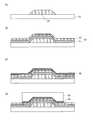
- FIG. 1is a diagram showing a configuration of a bottom gate type TFT 100 according to the first embodiment of the present invention. More specifically, FIG. 1A shows a bottom gate type TFT according to the first embodiment of the present invention.
- FIG. 1Bis a plan view showing the structure of the TFT 100
- FIG. 1Bis a cross-sectional view of the TFT 100 along the cutting line AA shown in FIG. 1A
- FIG. 2is a cross-sectional view of the TFT 100 taken along a cutting line BB shown in FIG.
- FIGS. 1A to 1Cthe structure of the TFT 100 will be described.
- a gate electrode 20is formed on a transparent insulating substrate 15 such as a glass substrate.
- the gate electrode 20may be made of any metal among, for example, titanium (Ti), molybdenum (Mo), aluminum (Al), tantalum (Ta), chromium (Cr), etc.
- Tititanium
- Momolybdenum
- Alaluminum
- Tatantalum
- Crchromium
- itmay be constituted by a laminated metal film in which titanium, aluminum, and titanium are laminated in order from the surface side of 15.
- a gate insulating film 30is formed so as to cover the entire insulating substrate 15 including the gate electrode 20.
- the gate insulating film 30is formed by stacking a silicon oxide (SiO 2 ) film 32 (also referred to as “first silicon oxide film”) on a silicon nitride (SiNx) film 31 (also referred to as “first silicon nitride film”). It is comprised by the laminated insulating film.
- the reason why the silicon nitride film 31 is includedis to ensure the withstand voltage of the gate insulating film 30.
- the reason why the silicon oxide film 32 is stacked on the silicon nitride film 31is as follows. The first reason is to facilitate supply of oxygen from the silicon oxide film 32 to the semiconductor layer 40 described later. The second reason is that if the semiconductor layer 40 is formed on the surface of the silicon nitride film 31, a trap is formed at the interface and the reliability of the TFT 100 is likely to be lowered.
- An island-shaped semiconductor layer 40is formed at a position on the surface of the gate insulating film 30 corresponding to the gate electrode 20.
- the semiconductor layer 40is made of IGZO (indium gallium zinc oxide) containing indium (In), gallium (Ga), zinc (Zn), and oxygen (O), and IGZO is an oxide semiconductor.
- IGZOindium gallium zinc oxide
- each end in the width direction of a region sandwiched between the source electrode 60a and the drain electrode 60bis cut out in a rectangular shape.
- the width of the region 40a (hereinafter referred to as “channel region 40a”) sandwiched between the source electrode 60a and the drain electrode 60b of the semiconductor layer 40is narrower than the width of the lower portion of the source electrode 60a and the drain electrode 60b. ing.
- the channel region 40a sandwiched between the regions 41 from which the semiconductor layer 40 has been cutincludes an end portion of the source electrode 60a and the drain electrode 60b.
- Two low-resistance regions 40b (also referred to as “first regions”) reduced by the source electrode 60a and the drain electrode 60bare formed along the end portions of the first and second electrodes.
- a high resistance region 40c (also referred to as “second region”) having a high resistance valueis formed in the center of the channel region 40a sandwiched between the two low resistance regions 40b.
- the film thickness of the semiconductor layer 40is preferably about 40 to 50 nm. This is because the following problems occur. That is, when the film thickness of the semiconductor layer 40 is thinner than 40 ⁇ m, the transistor characteristics of the TFT 100 become unstable, and the threshold voltage shifts due to temperature and gate stress voltage. On the other hand, when the film thickness is thicker than 50 nm, the controllability by the gate voltage is deteriorated, resulting in a problem that the off-current is increased.
- IGZO used as the semiconductor layer 40 of the TFT 100contains indium, gallium, and zinc in the same ratio. However, they may be included in different proportions.
- the IGZO constituting the semiconductor layer 40is most preferably amorphous, but may be microcrystalline.
- An oxide semiconductor that can be used as the semiconductor layer 40 of the TFT 100is not limited to IGZO, and may be an In—Zn—O system, an In—Zn—Sn—O system, an In—Zn—Si—O system, or the like. Good. Specifically, IZO (indium zinc oxide), ITO (indium tin oxide), ZnO, SnO (tin oxide), WO (tungsten oxide), IO (indium oxide), or the like may be used.
- the source electrode 60a and the drain electrode 60bare arranged on the upper surface of the semiconductor layer 40 so as to face each other with a predetermined distance.
- the source electrode 60 ais formed so as to extend from the upper left surface of the semiconductor layer 40 to the left gate insulating film 30.
- the drain electrode 60 bis formed so as to extend from the right upper surface of the semiconductor layer 40 to the right gate insulating film 30.
- the low resistance region 40b of the channel region 40ais formed not only in the channel region 40a but also in the semiconductor layer 40e protruding in the width direction from the side surfaces of the source electrode 60a and the drain electrode 60b.
- the semiconductor layer 40e protruding from the side surfaceis for securing an alignment margin when forming the source electrode 60a and the drain electrode 60b, and its width is 1/10 of the width of the source electrode 60a and the drain electrode 60b. It is as follows.
- the low resistance region formed in the semiconductor layer 40e protruding from the side surfaceis not directly related to the present invention, the description thereof is omitted in this specification.
- the source electrode 60a and the drain electrode 60bmay be made of any metal among, for example, titanium, aluminum, tantalum, tungsten, molybdenum, gold (Au), and the like, and from the surface side of the insulating substrate 15.
- titanium, aluminum, tantalum, tungsten, molybdenum, gold (Au), and the likemay be comprised by the laminated metal film which laminated
- the right end portion of the source electrode 60ais disposed above the left side portion of the gate electrode 20, and the left end portion of the drain electrode 60b is disposed above the right side portion of the gate electrode 20. For this reason, when a predetermined voltage is applied to the gate electrode 20, electrons are induced in each low resistance region 40 b of the semiconductor layer 40 by the electric field from the gate electrode 20, thereby forming a high concentration carrier layer. By forming the high concentration carrier layer, the source electrode 60a and the drain electrode 60b are ohmically connected to the two low resistance regions 40b, respectively.
- a passivation film 90is formed so as to cover the entire insulating substrate 15 including the source electrode 60a and the drain electrode 60b.
- the passivation film 90is made of silicon oxide having a thickness of 200 to 300 nm (also referred to as “second silicon oxide film”).
- the passivation film 90is a stacked insulating film in which a silicon oxide film (also referred to as “second silicon oxide film”) and a silicon nitride film (also referred to as “second silicon nitride film”) are sequentially stacked. May be. In this case, moisture entering from the outside is blocked by the silicon nitride film, so that each component of the TFT 100 can be prevented from being corroded by moisture. Thereby, the reliability of the TFT 100 can be ensured.
- a region where two low resistance regions 40b and a high resistance region 40c sandwiched between them are combined, that is, a region sandwiched between the source electrode 60a and the drain electrode 60bis referred to as a channel region 40a.
- a TFT in which a source electrode and a drain electrode covering a part of the upper surface of the semiconductor layerare sometimes referred to as a top contact TFT.
- a TFT in which the surface of the channel region is not covered with an etching stopper layeris sometimes referred to as a channel-etched TFT. Therefore, the TFT 100 is a TFT with a top contact structure and a TFT with a channel etch structure.
- FIGS. 2A to 2D and FIGS. 3A to 3Care process cross-sectional views showing each manufacturing process of the TFT 100.
- FIG. 2A to 2D and FIGS. 3A to 3Care process cross-sectional views showing each manufacturing process of the TFT 100.
- a metal film (not shown) to be the gate electrode 20is formed on the insulating substrate 15 by a sputtering method so as to have a film thickness of 100 to 300 nm.
- a resist pattern(not shown) is formed on the surface of the metal film using a photolithography method.
- the metal filmis etched by wet etching using the resist pattern as a mask to form the gate electrode 20. Thereafter, the resist pattern is peeled off.
- the insulating substrate 15 including the gate electrode 20is switched by using a plasma chemical vapor deposition method (Chemical Vapor Deposition: hereinafter referred to as “plasma CVD method”) to switch the source gas.
- plasma CVD methodChemical Vapor Deposition: hereinafter referred to as “plasma CVD method”
- a silicon nitride film 31 and a silicon oxide film 32are successively formed so as to cover the whole, and a gate insulating film 30 is formed.
- the thickness of the gate insulating film 30is 300 to 400 nm.
- the thickness of the silicon oxide film 32is preferably about 50 to 60% of the thickness of the gate insulating film 30.
- substrate temperatureis set to 300 to 400 ° C.
- the oxide semiconductor film 45is formed over the gate insulating film 30 by a sputtering method.
- the oxide semiconductor film 45is made of, for example, IGZO containing indium, gallium, zinc, and oxygen.
- the oxide semiconductor film 45uses a target in which indium oxide (In 2 O 3 ), gallium oxide (Ga 2 O 3 ), and zinc oxide (ZnO) are mixed in an equimolar amount and sintered, and DC (Direct Current).
- a filmis formed by sputtering.
- the thickness of the oxide semiconductor film 45is 40 to 50 nm.
- Sputteringis performed by introducing argon (Ar) gas having a flow rate of 100 to 300 sccm and oxygen (O 2 ) gas having a flow rate of 5 to 20 sccm into the chamber.
- the substrate temperature at this timeis set to 200 to 400.degree. Since the oxide semiconductor film 45 immediately after deposition contains a large amount of oxygen, the entire oxide semiconductor film 45 is a high resistance region. Note that the oxide semiconductor film 45 may be formed by a coating method instead of the sputtering method.
- an amorphous IGZO filmis formed by the above-described method, and then in an air atmosphere at 400 to 500 ° C. for about 1 to 2 hours. Annealing is performed.
- RTARapid Thermal Anneal
- RTAmay be performed in an inert gas atmosphere such as nitrogen (N 2 ) instead of annealing in an air atmosphere. RTA is performed, for example, at 500 to 750 ° C. for about 1 to 10 minutes.
- a resist pattern 48is formed on the surface of the oxide semiconductor film 45.
- the oxide semiconductor film 45is etched by dry etching to form an island-shaped semiconductor layer 40.
- the resist pattern 48is peeled off.
- notchesare formed at both ends in the width direction of the channel region of the semiconductor layer 40. Note that in the process of forming the semiconductor layer 40 having the notch, it is only necessary to replace the mask with a changed pattern, and there is no need to change the process or add a new process.
- a source metal film(not shown) is formed by sputtering.
- the film thickness of the formed source metal filmis 100 to 300 nm.
- a resist pattern 68 separated left and right at a predetermined distanceis formed on the source metal film above the gate electrode 20 by photolithography. Since the distance between the left and right ends of the resist pattern 68 is formed to be shorter than the length of the gate electrode 20, the resist pattern 68 covers the left and right ends of the gate electrode 20.
- the source metal filmis etched by dry etching to form a source electrode 60a and a drain electrode 60b.
- the source electrode 60 aextends from the upper left surface of the semiconductor layer 40 to the left gate insulating film 30.
- the drain electrode 60 bextends from the right upper surface of the semiconductor layer 40 to the right gate insulating film 30.
- the resist pattern 68is peeled off.
- the etching stopper layeris not formed on the surface of the semiconductor layer 40, in order to suppress the etching of the surface of the semiconductor layer 40 as much as possible, an etching condition with a high selectivity between the source metal film and the semiconductor layer 40 is used. It is preferable to etch the source metal film.
- a passivation film 90 made of silicon oxideis formed by plasma CVD so as to cover the entire insulating substrate 15 including the source electrode 60a and the drain electrode 60b.
- the passivation film 90is in contact with the semiconductor layer 40.
- the passivation film 90is preferably made of silicon oxide in order to supply oxygen to IGZO constituting the semiconductor layer 40, and the film thickness is preferably 200 to 300 nm.
- the substrate temperature during film formationis 200 to 300.degree.
- the low resistance region 40bis formed in the vicinity of the source electrode 60a and the drain electrode 60b of the semiconductor layer 40 along the end portions thereof. Further, oxygen is also released from the high resistance region sandwiched between the two low resistance regions 40b, and the middle resistance region 40d is formed.
- annealingalso referred to as “heat treatment” is performed in a dry air atmosphere at 200 to 400 ° C. for about 1 to 2 hours.
- oxygen from the outside and oxygen from silicon oxide constituting the passivation film 90are supplied to the semiconductor layer 40 in which oxygen is reduced.
- the area of the low resistance region 40b formed at the time of forming the passivation film 90is reduced, and oxygen is also supplied to the middle resistance region 40d to become the high resistance region 40c.
- annealingmay be performed not in a dry air atmosphere but in an oxygen atmosphere or an atmosphere containing oxygen.
- the annealing of the passivation film 90may be performed in an oxygen-free atmosphere, for example, a nitrogen atmosphere. Also in this case, a TFT having normal transistor characteristics is manufactured. This is presumably because oxygen was supplied from silicon oxide constituting the passivation film 90 or excessive oxygen was present in the channel region 40a.
- the Oxidation of the oxide semiconductor in the channel region 40aproceeds by incorporating oxygen, and the area of the low-resistance region 40b becomes narrow, and the middle-resistance region 40d becomes a high-resistance region 40c having a higher resistance value. Accordingly, the off current of the TFT 100 becomes 1 ⁇ 10 ⁇ 10 to 10 ⁇ 11 A, and the TFT 100 sufficiently functions as a switching element of the liquid crystal display device.
- the width of the source electrode 60a and the drain electrode 60bis made wider than the width of the channel region 40a of the semiconductor layer 40, and the surface of the semiconductor layer 40 is exposed to the source electrode 60a and the drain electrode 60b. There is no opening. Thereby, since the source electrode 60a and the drain electrode 60b are in electrical contact with the semiconductor layer 40 over the entire back surface, the contact resistance between the source electrode 60a and the drain electrode 60b and the semiconductor layer 40 can be kept low. As a result, a decrease in the on-current of the TFT 100 can be prevented, so that the on / off ratio can be increased.
- the oxygen supplied to the semiconductor layer 40 from the outside by annealing in a dry air atmosphereis larger when the oxide semiconductor constituting the semiconductor layer 40 is amorphous than when it is microcrystalline. Accordingly, when the oxide semiconductor is amorphous, the channel region 40a is further oxidized and the area of the low-resistance region 40b is further narrowed and the medium-resistance region is smaller than when the oxide semiconductor is microcrystalline. 40d becomes a high resistance region 40c having a higher resistance value. This is considered to be because oxygen from the outside is hardly supplied to the channel region 40a because the film density of the oxide semiconductor made of microcrystals is high.
- FIG. 4is a diagram showing the positional relationship between the foreign matter 99 and the channel region 40a. More specifically, FIG. 4A shows the foreign matter 99 and the channel region when notch portions are not provided at both ends of the channel region 44a. 4B is a diagram showing the positional relationship between the foreign matter 99 and the channel region 40a when the notch portions 41 are provided at both ends of the channel region 40a.
- etching gasfor example, a fluorine-based gas such as methane tetrafluoride (CF 4 ), or boron trichloride (BCl 3 ) or Cl 2 (chlorine). Chlorine gas such as) is used.
- a fluorine-based gassuch as methane tetrafluoride (CF 4 ), or boron trichloride (BCl 3 ) or Cl 2 (chlorine).
- CF 4methane tetrafluoride
- BCl 3boron trichloride
- Cl 2Cl 2
- These metal fluorides or metal chlorides adhering to the inner wall of the plasma CVD apparatus at the time of etchingmay be peeled off from the inner wall during the etching or after the etching is finished and fall onto the source metal film.
- one end of the fallen foreign material 99is in electrical contact with the low resistance region 44b of the semiconductor layer 44 adjacent to the source electrode 60a in the subsequent process, and the other end is In some cases, the low resistance region 40b of the semiconductor layer 44 adjacent to the drain electrode 60b is in electrical contact.
- the source electrode 60a and the drain electrode 60bare short-circuited by being electrically connected via the two low-resistance regions 44b and the foreign matter 99.
- the TFT 100even if the foreign matter 99 made of metal chloride or metal fluoride falls at the same position as in FIG. A notch 41 is formed by etching when the layer 40 is formed. In this case, the position where the foreign material 99 has fallen is the cutout portion 41, and thus the low resistance region 40b is not formed. For this reason, the source electrode 60a and the drain electrode 60b are not short-circuited by the foreign matter 99. Thus, in the TFT 100, the possibility of a short circuit between the source electrode 60a and the drain electrode 60b due to the foreign matter 99 can be reduced.
- FIG. 5is a diagram showing the influence of multiple reflection. More specifically, FIG. 5A is a diagram showing the influence of multiple reflection when notches are not provided at both ends of the channel region 44a. FIG. 5B is a diagram showing the influence of multiple reflection when notches 41 are provided at both ends of the channel region 40a. As shown in FIG. 5A, the backlight light applied to the conventional TFT from the back surface side is directed toward the channel region 44a while being repeatedly reflected between the surface of the gate electrode 20 and the back surface of the drain electrode 60b. Go ahead.
- the backlight lightWhen the backlight light reaches the channel region 44a, it is absorbed by the semiconductor layer 44 in the channel region 44a and generates conduction electrons in the channel region 44a. As described above, in a TFT not provided with a notch, a current easily flows due to multiple reflection of backlight light.
- the backlight light traveling while repeating multiple reflections between the surface of the gate electrode 20 and the back surface of the drain electrode 60bis The channel region 40a of the semiconductor layer 40 is reached.
- the cutout portion 41the backlight light passes through the cutout portion 41.
- the backlight lightis not absorbed by the channel region 40a, conduction electrons are not generated in the channel region 40a. For this reason, in TFT100, the electric current by the multiple reflection of backlight light can be suppressed.
- FIG. 6is a diagram showing the relationship between the channel length and the channel width at the time of designing to operate as the TFT 100.
- FIG. 7is an expected plan view showing the shape of the low resistance region, and more specifically, FIG. 7A is an expected plan view showing the shape of the low resistance region 44b in the case where the notch portion is not provided.
- FIG. 7Bis an expected plan view showing the shape of the low resistance region 40b when the notch 41 is provided.
- the length of the low resistance region 40b in the channel direction formed in the channel region 40ais assumed to be constant regardless of the channel width. However, in practice, as shown in FIG. 6, when the channel width becomes narrower than 20 ⁇ m, the phenomenon that the channel length also becomes short accompanying it appears.
- the length of the low resistance region 44b in the channel directionis not constant but varies irregularly according to the channel width.
- the tip of the low resistance region 44b on the source electrode 60a side and the tip of the low resistance region 44b on the drain electrode 60b sideoverlap.
- the source electrode 60a and the drain electrode 60bmay be electrically connected (see FIG. 7A).
- the TFTsince the current cannot be controlled by the gate electrode 20, it always flows between the current source electrode 60a and the drain electrode 60b. In this case, the TFT operates not as a transistor but as a resistance element.
- the notch 41is provided in the channel region 40 a of the semiconductor layer 40, the low resistance region 40 b is not formed in the notch 41. Therefore, as shown in FIG. 7B, when a portion (a portion indicated by a dotted line) in which the length in the channel direction of the low resistance region 40b is increased is formed at the same position as FIG. It is possible to prevent the tip of the low resistance region 40b on the source electrode 60a side and the tip of the low resistance region 40b on the drain electrode 60b side from overlapping each other. In addition, it is expected that the irregular shape change of the low resistance region 40b is suppressed to some extent by providing the notch 41. From these things, it is presumed that the possibility that the tips of the low resistance regions 40b overlap each other is reduced. For this reason, it is estimated that the TFT 100 is less likely to operate as a resistance element.
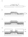
- FIG. 8is a diagram illustrating a configuration of a bottom gate TFT 200 according to a modification of the present embodiment. More specifically, FIG. 8A illustrates a configuration of the bottom gate TFT 200 according to a modification of the present embodiment.
- 8Bis a cross-sectional view of the TFT 200 along the cutting line CC shown in FIG. 8A
- FIG. 8Cis a cross-sectional view shown in FIG. 8A.
- FIG. 10is a cross-sectional view of the TFT 200 along line DD.
- the constituent elements of the TFT 200the same constituent elements as those of the TFT 100 shown in FIGS. 1A to 1C are denoted by the same reference numerals, and different constituent elements will be mainly described.
- a notch 41is provided only at one end of the channel region 40a.
- the width of the channel region 40ais wider in the TFT 200 than in the TFT 100.
- the same effects as the effects exhibited by the TFT 100can be obtained.
- the notch 41 of the TFT 200is provided only on one side, the effect is half of the effect produced by the TFT 100.
- FIG. 9is a diagram showing a configuration of a bottom gate type TFT 300 according to the second embodiment of the present invention. More specifically, FIG. 9A shows a bottom gate type TFT according to the second embodiment of the present invention. 9B is a plan view showing the structure of the TFT 300, FIG. 9B is a cross-sectional view of the TFT 300 along the cutting line EE shown in FIG. 9A, and FIG. 9C is FIG. 2 is a cross-sectional view of the TFT 300 taken along a cutting line FF shown in FIG.
- the constituent elements of the TFT 300the same constituent elements as those of the TFT 100 shown in FIGS. 1A to 1C are denoted by the same reference numerals, and different constituent elements will be mainly described.
- the notches 41are provided at both ends of the channel region 40a of the semiconductor layer 40, but also the channel region 40a.
- a notch 42(also referred to as “second notch”) is also provided at the center of the notch.
- the notch 42has a rectangular shape whose length in the channel direction is determined by the ends of the source electrode 60a and the drain electrode 60b. In the cutout portion 42, the semiconductor layer 40 is cut off, so that the surface of the silicon oxide film 32 underneath is exposed.
- the mask used for forming the semiconductor layer 40 in the process shown in FIG. 2C among the manufacturing processes of the TFT 100 described in the first embodimentis replaced with a new notch 42. It is only necessary to replace the mask with the opening pattern to be added, and there is no need to change the process or add a new process.
- the channel region 40ahas a rectangular notch whose length in the channel direction is determined by the ends of the source electrode 60a and the drain electrode 60b not only at both ends but also in the center. A portion 42 is formed.
- the TFT 300has the same effect as that of the TFT 100. Specifically, by providing the notch portion 42, the area of the side surface of the semiconductor layer 40 is further increased. Therefore, oxygen from the outside and the silicon oxide film 32 are formed in the low resistance region 40b and the middle resistance region 40d. In addition, oxygen contained in the passivation film 90 is easily supplied.
- the oxide semiconductor constituting the channel region 40ais further oxidized by taking in more oxygen, and the area of the low resistance region 40b is further narrowed.
- the middle resistance region 40dbecomes a high resistance region 40c having a higher resistance value. Therefore, the off current (leakage current) of the TFT 300 is 1 ⁇ 10 ⁇ 10 to 10 ⁇ 11 A, and the TFT 300 functions sufficiently as a switching element of the liquid crystal display device.
- the source electrode 60a and the drain electrode 60bare short-circuited by foreign matters generated when the source electrode 60a and the drain electrode 60b are formed, or the backlight is subjected to multiple reflection between the surface of the gate electrode 20 and the surface of the drain electrode 60b. It is possible to further reduce the possibility that a current is generated due to this. Furthermore, since the low resistance region 40b on the source electrode 60a side and the low resistance region 40b on the drain electrode 60b side overlap, the possibility that the source electrode 60a and the drain electrode 60b are short-circuited can be further reduced.
- the cutout portion 42is formed at the center of the channel region 40a in the channel width direction.
- one or a plurality of the cutout portions 42may be formed at an arbitrary position in the channel region 40a.
- one or a plurality of the notch portions 42are formed at positions away from the end portions of the channel region 40a. May be.
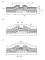
- FIG. 10is a diagram illustrating a configuration of a top-gate thin film transistor 400 according to the third embodiment of the present invention. More specifically, FIG. 10A illustrates a top according to the third embodiment of the present invention.
- FIG. 10Bis a cross-sectional view of the TFT 400 taken along a cutting line GG shown in FIG. 10A
- FIG. 10Cis a plan view showing the structure of the gate type thin film transistor 400.
- FIG. 11is a cross-sectional view of the TFT 400 taken along a cutting line HH shown in FIG.
- the same components as those of the TFT 100 shown in FIGS. 1A to 1Care denoted by the same reference numerals, and different components will be mainly described.
- the source electrode 70a and the drain electrode 70bare formed on the gate insulating film 30 including the silicon nitride film 31 and the silicon oxide film 32. Is formed.
- a semiconductor layer 50is formed on the surfaces of the source electrode 70a and the drain electrode 70b.
- the semiconductor layer 50is electrically connected to the source electrode 70a and the drain electrode 70b on the back surface thereof.
- notches 51hereinafter also referred to as “notches” or “first notches” are formed at both ends in the channel width direction.
- the entire insulating substrate 15 including the semiconductor layer 50, the source electrode 70 a and the drain electrode 70 bis covered with a passivation film 90.
- a region where two low resistance regions 50b and a high resistance region 50c sandwiched between them are combined, that is, a region sandwiched between the source electrode 60a and the drain electrode 60bis referred to as a channel region 50a.
- FIG. 11A to FIG. 11D and FIG. 12A to FIG. 12Care process cross-sectional views showing each manufacturing process of the TFT 400.
- FIGS. 11 (A) to 11 (D) and FIGS. 12 (A) to 11 (C)FIGS. 2 (A) to 2 (D) and FIGS. 3 (A) to 3
- the same steps as those shown in (C)will be briefly described, and different steps will be mainly described.
- membrane formed at each process, process conditions, etc.are the same as the case of 1st Embodiment, those description is abbreviate
- the gate electrode 20is formed on the insulating substrate 15.
- a gate insulating film 30 including a silicon nitride film 31 and a silicon oxide film 32is formed so as to cover the insulating substrate 15 including the gate electrode 20.
- a source metal film 75is formed on the gate insulating film 30 by a sputtering method.
- a resist pattern 78 having an openingis formed over the gate electrode 20, the source metal film 75 is etched using the resist pattern 78 as a mask, and a source electrode 70a and a drain electrode 70b are formed. Form. Thereafter, the resist pattern 78 is peeled off.
- oxidationis performed by sputtering so as to cover the entire insulating substrate 15 including the gate insulating film 30, the source electrode 70a, and the drain electrode 70b sandwiched between the source electrode 70a and the drain electrode 70b.
- a physical semiconductor film 55is formed.
- a resist pattern 58is formed on the oxide semiconductor film 55 above the gate electrode 20 using a mask in which a pattern for forming the channel region 50a is formed. Since the oxide semiconductor film 55 immediately after film formation contains a large amount of oxygen, the entire oxide semiconductor film 55 is a high resistance region.
- the oxide semiconductor film 55is etched using the resist pattern 58 as a mask to form the semiconductor layer 50. Thereafter, the resist pattern 58 is removed, and a passivation film 90 is formed so as to cover the entire insulating substrate 15 including the semiconductor layer 50, the source electrode 70a, and the drain electrode 70b.
- the insulating substrate 15is heated when the passivation film 90 is formed. For this reason, the source electrode 70 a and the drain electrode 70 b take oxygen from the semiconductor layer 50 and supply the hydrogen to the semiconductor layer 50, thereby reducing the semiconductor layer 50.
- a low resistance region 50b(also referred to as “first region”) is formed in the semiconductor layer 50 close to the source electrode 70a and the drain electrode 70b. Further, oxygen is also released from the high resistance region sandwiched between the two low resistance regions 50b, and the middle resistance region 50d is formed.
- oxygen from the outside and oxygen contained in the silicon oxide film 32 and the passivation film 90are supplied to the channel region 50a of the semiconductor layer 50 by annealing in a dry air atmosphere. .
- the area of the low resistance region 50bis reduced, and the resistance value of the middle resistance region 50d is increased to become the high resistance region 50c (also referred to as “second region”).
- the area of the low-resistance region 50b of the channel region 50ais narrowed and the channel region sandwiched between the low-resistance regions 50b is the same as the effect exhibited by the TFT 100 according to the first embodiment.
- a high resistance region 50cis formed in 50a. Further, it is possible to reduce the possibility that the source electrode 70a and the drain electrode 70b are short-circuited by a foreign substance, or that current is generated due to multiple reflection of backlight light. Furthermore, the possibility that the source electrode 70a and the drain electrode 70b are short-circuited by the overlap of the low resistance region 50b on the source electrode 70a side and the low resistance region 50b on the drain electrode 70b side can be reduced.
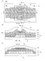
- FIG. 13is a diagram showing a configuration of a bottom gate type TFT 500 according to the fourth embodiment of the present invention. More specifically, FIG. 13A shows a bottom gate type TFT according to the fourth embodiment of the present invention.
- FIG. 13Bis a cross-sectional view of the TFT 500 taken along a cutting line JJ shown in FIG. 13A
- FIG. 13Cis a plan view showing the structure of the TFT 500.
- FIG. 2is a cross-sectional view of the TFT 500 along the cutting line KK shown in FIG.
- the constituent elements of the TFT 500the same constituent elements as those of the TFT 100 shown in FIGS. 1A to 1C are denoted by the same reference numerals, and different constituent elements will be mainly described.
- both end portions of the channel region 40a of the semiconductor layer 40are removed by etching to form a notch 41.
- the etching stopper layer 80is formed on the channel region 40 a of the semiconductor layer 40. The etching stopper layer 80 protects the surface of the semiconductor layer 40 from being etched when the source metal film is etched to form the source electrode 60a and the drain electrode 60b.
- the etching stopper layer 80is made of silicon oxide. For this reason, as will be described later, the etching stopper layer 80 can supply oxygen to the channel region 40 a of the semiconductor layer 40 together with the passivation film 90. Note that a TFT in which an etching stopper layer is formed on the surface of a semiconductor layer like the TFT 500 may be referred to as an etch stop TFT.
- FIGS. 14A to 14D and FIGS. 15A to 15Care process cross-sectional views illustrating each manufacturing process of the TFT 500.
- the same steps as those shown in (C)will be briefly described, and different steps will be mainly described.
- membrane formed in each process, process conditions, etc.are the same as the case of 1st Embodiment, those description is abbreviate
- the gate electrode 20is formed on the insulating substrate 15.
- a gate insulating film 30composed of a silicon nitride film 31 and a silicon oxide film 32 is formed so as to cover the entire insulating substrate 15 including the gate electrode 20.
- An oxide semiconductor film(not shown) is formed on the gate insulating film 30 by a sputtering method. Since the oxide semiconductor film immediately after deposition contains a large amount of oxygen, the entire oxide semiconductor film is a high-resistance region. As shown in FIG. 14C, a resist pattern 48 is formed over the oxide semiconductor film above the gate electrode 20. The oxide semiconductor film is etched using the resist pattern 48 as a mask to form the semiconductor layer 40. Thereafter, the resist pattern 48 is peeled off.
- a silicon oxide film 85is formed by plasma CVD so as to cover the entire insulating substrate 15 including the semiconductor layer 40.
- the thickness of the silicon oxide film 85is 50 to 200 nm.
- a resist pattern 88is formed on the silicon oxide film 85.
- the silicon oxide film 85is etched using the resist pattern 88 as a mask to form an etching stopper layer 80.
- the resist pattern 88is peeled off, and a source metal film 65 is formed using a sputtering method so as to cover the entire insulating substrate 15 including the etching stopper layer 80.
- a resist pattern 68 separated on the left and right on the etching stopper layeris formed on the source metal film 65.
- the source metal film 65is etched using the resist pattern 68 as a mask to form a source electrode 60a and a drain electrode 60b separated on the left and right on the etching stopper layer 80. Thereafter, the resist pattern 68 is peeled off.
- the entire insulating substrate 15 including the etching stopper layer 80, the source electrode 60a, and the drain electrode 60bis covered with a passivation film 90.
- the insulating substrate 15is heated when the passivation film 90 is formed. Therefore, the source electrode 60 a and the drain electrode 60 b take oxygen from the semiconductor layer 40 and reduce the semiconductor layer 40 by supplying hydrogen to the semiconductor layer 40.
- the low resistance region 40bis formed in the semiconductor layer 40 in the vicinity of the ends of the source electrode 60a and the drain electrode 60b. Since the etching stopper layer is formed on the high resistance region sandwiched between the two low resistance regions 40b, oxygen is not easily released from the high resistance region and remains as the high resistance region 40c.
- oxygenis supplied from the silicon oxide constituting the etching stopper layer 80 to the IGZO constituting the channel region 40a.
- the low resistance region 40btakes in oxygen and its area becomes narrow.
- the area of the low-resistance region 40b of the channel region 40ais narrowed and the channel region sandwiched between the low-resistance regions 40b is the same as the effect exhibited by the TFT 100 according to the first embodiment.
- a high resistance region 40cis formed in 40a.
- the possibility that the source electrode 60a and the drain electrode 60b are short-circuited by the overlap of the low resistance region 40b on the source electrode 60a side and the low resistance region 40b on the drain electrode 60b sidecan be reduced.
- TFT>typical TFTs 100 to 500 are described among TFTs to which the present invention can be applied. However, other TFTs obtained by appropriately combining these TFTs 100 to 500 have the same effect.
- the notch 51 of the semiconductor layer 50is provided not only at both ends in the width direction of the channel region 50a, but also by providing one or more between them. May be.
- the TFT 500 with the TFT 500, in the channel stop structure TFTone or a plurality of notches 41 of the semiconductor layer 40 are provided not only at both ends in the width direction of the channel region 40a but also between them. May be.
- the notch 51 of the semiconductor layer 50is formed on one side in the width direction of the channel region 50a and on the inner side along the length direction of the channel region 50a. One or more may be provided at the position.
- FIG. 16is a block diagram showing a configuration of the liquid crystal display device 10 including the TFT 100 according to the first embodiment.
- a liquid crystal display device 10 illustrated in FIG. 16includes a liquid crystal panel 2 (also referred to as a “display unit”), a display control circuit 3, a gate driver 4, and a source driver 5.
- the liquid crystal panel 2includes n (n is an integer of 1 or more) gate wirings G1 to Gn extending in the horizontal direction and m (m is an integer of 1 or more) extending in a direction intersecting the gate wirings G1 to Gn.
- Source wirings S1 to Smare formed.
- Pixel forming portions Pijare arranged near intersections of the i-th gate line Gi (i is an integer of 1 to n) and the j-th source line Sj (j is an integer of 1 to m). .
- the display control circuit 3is supplied with a control signal SC such as a horizontal synchronizing signal and a vertical synchronizing signal and an image signal DT from the outside of the liquid crystal display device 10. Based on these signals, the display control circuit 3 outputs a control signal SC1 to the gate driver 4, and outputs a control signal SC2 and an image signal DT to the source driver 5.
- a control signal SCsuch as a horizontal synchronizing signal and a vertical synchronizing signal and an image signal DT
- the gate driver 4is connected to the gate lines G1 to Gn, and the source driver 5 is connected to the source lines S1 to Sm.
- the gate driver 4sequentially applies a high level signal indicating the selected state to the gate lines G1 to Gn.
- the gate wirings G1 to Gnare sequentially selected one by one. For example, when the i-th gate line Gi is selected, the pixel formation portions Pi1 to Pim for one row are selected at once.
- the source driver 5applies a signal voltage corresponding to the image signal DT to each of the source lines S1 to Sm. As a result, the signal voltage corresponding to the image signal DT is written into the pixel formation portions Pi1 to Pim for one selected row. In this way, the liquid crystal display device 10 displays an image on the liquid crystal panel 2.
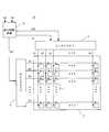
- FIG. 17is a plan view showing a pattern arrangement in the pixel formation portion Pij provided in the liquid crystal panel 2.
- the liquid crystal panel 2is surrounded by an i-th gate line Gi extending in the horizontal direction, a j-th source line Sj extending in a direction intersecting the gate line Gi, the gate line Gi, and the source line Sj.
- a pixel forming portion Pijdisposed in the region.
- the pixel formation portion Pijincludes a TFT 100 shown in FIGS. 1A to 1C as a TFT functioning as a switching element.
- the gate electrode 20 of the TFT 100is electrically connected to the gate wiring Gi.
- An island-shaped semiconductor layer 40is formed above the gate electrode 20.
- One end of the semiconductor layer 40is electrically connected to the source electrode 60a connected to the source wiring Sj, and the other end of the semiconductor layer 40 is electrically connected to the drain electrode 60b. Further, the drain electrode 60 b is electrically connected to the pixel electrode 7 through the contact hole 6.
- the pixel electrode 7 and a counter electrodeconstitute a pixel capacitor that holds a signal voltage corresponding to the image signal DT for a predetermined time.
- the display quality of the liquid crystal display device 10can be improved by using the TFT 100 having a large on / off ratio as a switching element of each pixel formation portion Pij provided in the liquid crystal panel 2.
- the reason why the display quality of the liquid crystal display device 10 is improved by increasing the on / off ratiowill be described.
- the on-currentmay be increased and the off-current may be decreased.
- the signal voltage of the image signal DT supplied from the source wiring Sjcan be charged to the pixel capacitor (the pixel capacitor and the auxiliary capacitor when the auxiliary capacitor is also formed) in a short time.
- the number of formation parts Pijcan be increased.
- the signal voltage written in the pixel capacitorcan be held for a long time by reducing the off-state current.
- the present inventioncan also be applied to an organic EL (Electro Luminescence) display device.
- the present inventionis suitable for a thin film transistor used in a display device such as an active matrix liquid crystal display device, and is particularly suitable for a thin film transistor used as a switching element formed in the pixel formation portion.
- SYMBOLS 10Liquid crystal display device 15 ... Insulating substrate 20 ... Gate electrode 30 ... Gate insulating film 31 ... Silicon nitride film 32 ... Silicon oxide film 40, 50 ... Semiconductor layer 40a, 50a ... Channel region 40b, 50b ... Low resistance region 40c, 50c ... high resistance regions 41, 51 ... notches 42 ... notches 60a, 70a ... source electrodes 60b, 70b ... drain electrodes 80 ... etching stopper layer 90 ... passivation film 100-500 ... TFT (thin film transistor)
Landscapes
- Thin Film Transistor (AREA)
Abstract
Description
Translated fromJapanese本発明は、薄膜トランジスタ、その製造方法、および表示素子に関し、特に、酸化物半導体からなる半導体層を有する薄膜トランジスタ、その製造方法、および表示素子に関する。The present invention relates to a thin film transistor, a manufacturing method thereof, and a display element, and more particularly to a thin film transistor having a semiconductor layer made of an oxide semiconductor, a manufacturing method thereof, and a display element.
酸化インジウムガリウム亜鉛(以下、「IGZO」という)または酸化亜鉛(ZnO)等の酸化物半導体からなる半導体層を有する薄膜トランジスタ(Thin Film Transistor:以下、「TFT」という)は、非晶質シリコンからなる半導体層を有するTFTに比べて動作速度が速く、また多結晶シリコンからなる半導体層を有するTFTに比べて、結晶化工程が不要になる等の優れた特徴を有している。A thin film transistor (hereinafter referred to as “TFT”) having a semiconductor layer made of an oxide semiconductor such as indium gallium zinc oxide (hereinafter referred to as “IGZO”) or zinc oxide (ZnO) is made of amorphous silicon. Compared with a TFT having a semiconductor layer made of polycrystalline silicon, it has excellent features such as a higher operating speed than a TFT having a semiconductor layer and no need for a crystallization step.
しかし、酸化物半導体からなる半導体層は、その後の製造工程で基板全体が加熱される際に還元されてしまう。具体的には、半導体層は、ソース電極およびドレイン電極によって酸素を奪い取られるとともに、ソース電極およびドレイン電極から水素を供給される。このようにして、半導体層の形成直後には、半導体層の全体が高抵抗領域である。しかし、酸化物半導体を還元することによって、ソース電極およびドレイン電極と直接接する半導体層およびそれらの電極の端部に近い半導体層は低抵抗領域になり、両側の低抵抗領域に挟まれた半導体層は、その抵抗値が低抵抗領域と高抵抗領域との間である領域(以下、「中抵抗領域」という)になる。このような半導体層をチャネル層とするTFTでは、オフ電流が大きくなったり、半導体層が抵抗素子として動作したりしてしまう。However, the semiconductor layer made of an oxide semiconductor is reduced when the entire substrate is heated in the subsequent manufacturing process. Specifically, the semiconductor layer is deprived of oxygen by the source electrode and the drain electrode and supplied with hydrogen from the source electrode and the drain electrode. Thus, immediately after the formation of the semiconductor layer, the entire semiconductor layer is a high resistance region. However, by reducing the oxide semiconductor, the semiconductor layer that is in direct contact with the source electrode and the drain electrode and the semiconductor layer near the ends of those electrodes become a low resistance region, and the semiconductor layer sandwiched between the low resistance regions on both sides Is a region whose resistance value is between the low resistance region and the high resistance region (hereinafter referred to as “medium resistance region”). In a TFT having such a semiconductor layer as a channel layer, off current increases, or the semiconductor layer operates as a resistance element.
特許文献1には、酸化物半導体からなる半導体層に、外部から酸素を供給しやすくすることによって、良好なトランジスタ特性を回復させることができるTFTが開示されている。具体的には、TFTのソース電極およびドレイン電極の形成後に、ソース電極およびドレイン電極に、半導体層の表面を露出させるための開口部を形成する。次に、高温下で酸素アニールを行うことにより、開口部から半導体層に酸素を供給する。これにより、TFTは良好なトランジスタ特性を回復する。
特許文献1では、半導体層に酸素を供給するために、ソース電極およびドレイン電極に開口部を形成する。しかし、開口部を形成することによって、ソース電極およびドレイン電極と半導体層との接触面積が減少するので、ソース電極およびドレイン電極と半導体層とのコンタクト抵抗が高くなる。これにより、TFTのオン電流が低下する等、トランジスタ特性が悪影響を受ける。In
そこで、ソース電極およびドレイン電極と酸化物半導体からなる半導体層とのコンタクト抵抗を低く保った状態で、良好なトランジスタ特性を回復させることができる薄膜トランジスタを提供することを目的とする。Therefore, an object of the present invention is to provide a thin film transistor capable of recovering good transistor characteristics while maintaining a low contact resistance between a source electrode and a drain electrode and a semiconductor layer made of an oxide semiconductor.
本発明の第1の局面は、絶縁基板上に形成され、酸化物半導体からなる半導体層を有する薄膜トランジスタであって、
前記絶縁基板上に形成されたゲート電極と、
前記ゲート電極を覆うように形成され、少なくとも第1の酸化シリコン膜を含むゲート絶縁膜と、
前記ゲート電極を挟むように、所定の距離を隔てて前記ゲート絶縁膜上に形成されたソース電極およびドレイン電極と、
前記ソース電極および前記ドレイン電極によって挟まれた前記ゲート絶縁膜上に形成され、一端および他端が前記ソース電極および前記ドレイン電極の裏面または表面のいずれかとそれぞれ電気的に接続された前記半導体層と、
前記ソース電極、前記ドレイン電極、および前記半導体層を覆い、少なくとも第2の酸化シリコン膜を含むパッシベーション膜とを備え、
前記半導体層は、前記ソース電極および前記ドレイン電極の裏面または表面と接する領域における幅よりも、前記ソース電極と前記ドレイン電極とによって挟まれたチャネル領域における幅が狭く、
前記チャネル領域は、前記第1の酸化シリコン膜と前記第2の酸化シリコン膜とによって挟まれていることを特徴とする。A first aspect of the present invention is a thin film transistor having a semiconductor layer formed on an insulating substrate and made of an oxide semiconductor,
A gate electrode formed on the insulating substrate;
A gate insulating film formed to cover the gate electrode and including at least a first silicon oxide film;
A source electrode and a drain electrode formed on the gate insulating film at a predetermined distance so as to sandwich the gate electrode;
The semiconductor layer formed on the gate insulating film sandwiched between the source electrode and the drain electrode, and having one end and the other end electrically connected to either the back surface or the surface of the source electrode and the drain electrode, respectively ,
A passivation film that covers the source electrode, the drain electrode, and the semiconductor layer and includes at least a second silicon oxide film;
The semiconductor layer has a narrower width in a channel region sandwiched between the source electrode and the drain electrode than a width in a region in contact with the back surface or the front surface of the source electrode and the drain electrode,
The channel region is sandwiched between the first silicon oxide film and the second silicon oxide film.
本発明の第2の局面は、本発明の第1の局面において、
前記チャネル領域は、少なくとも幅方向のいずれか一方の端部に第1の切り欠き部を有することを特徴とする。According to a second aspect of the present invention, in the first aspect of the present invention,
The channel region has a first cutout at least at one end in the width direction.
本発明の第3の局面は、本発明の第2の局面において、
前記チャネル領域は、幅方向の両端部に前記第1の切り欠き部を有することを特徴とする。According to a third aspect of the present invention, in the second aspect of the present invention,
The channel region has the first notch at both ends in the width direction.
本発明の第4の局面は、本発明の第1から第3のいずれかの局面において、
前記チャネル領域は、幅方向の端部から内側に離れた位置に、前記チャネル領域の長さ方向に沿って少なくとも1つの第2の切り欠き部を有することを特徴とする。According to a fourth aspect of the present invention, in any one of the first to third aspects of the present invention,
The channel region has at least one second cutout portion along a length direction of the channel region at a position spaced inward from an end portion in the width direction.
本発明の第5の局面は、本発明の第1の局面において、
前記ゲート絶縁膜は、前記第1の酸化シリコン膜の下面に形成された第1の窒化シリコン膜をさらに含み、
前記パッシベーション膜は、第2の酸化シリコン膜の表面に形成された第2の窒化シリコン膜をさらに含むことを特徴とする。According to a fifth aspect of the present invention, in the first aspect of the present invention,
The gate insulating film further includes a first silicon nitride film formed on a lower surface of the first silicon oxide film,
The passivation film further includes a second silicon nitride film formed on the surface of the second silicon oxide film.
本発明の第6の局面は、本発明の第1の局面において、
前記ソース電極と前記ドレイン電極とは、前記半導体層上に、所定の距離を隔てて対向するように形成され、
前記半導体層は、前記一端が前記ソース電極の裏面と電気的に接続され、前記他端が前記ドレイン電極の裏面と電気的に接続されるように形成されていることを特徴とする。According to a sixth aspect of the present invention, in the first aspect of the present invention,
The source electrode and the drain electrode are formed on the semiconductor layer so as to face each other with a predetermined distance therebetween,
The semiconductor layer is formed so that the one end is electrically connected to the back surface of the source electrode and the other end is electrically connected to the back surface of the drain electrode.
本発明の第7の局面は、本発明の第6の局面において、
前記ソース電極と前記ドレイン電極とに挟まれた前記半導体層上に形成された、酸化シリコンからなるエッチングストッパ層をさらに備え、
前記チャネル領域は、前記ソース電極と前記ドレイン電極の端部に沿ってそれぞれ形成された、抵抗値が低い2つの第1の領域と、前記2つの第1の領域によって挟まれ、前記2つの第1の領域よりも抵抗値が高い第2の領域とを含み、
前記エッチングストッパ層は、少なくとも前記第2の領域を覆うように形成されていることを特徴とする。A seventh aspect of the present invention is the sixth aspect of the present invention,
An etching stopper layer made of silicon oxide formed on the semiconductor layer sandwiched between the source electrode and the drain electrode;
The channel region is sandwiched between two first regions each having a low resistance value formed along the ends of the source electrode and the drain electrode, and the two first regions. A second region having a resistance value higher than that of the first region,
The etching stopper layer is formed so as to cover at least the second region.
本発明の第8の局面は、本発明の第1の局面において、
前記ソース電極と前記ドレイン電極とは、前記ゲート絶縁膜上に所定の距離を隔てて対向するように形成され、
前記半導体層は、前記一端が前記ソース電極の端部を覆って前記ソース電極の表面と電気的に接続され、前記他端が前記ドレイン電極の端部を覆って前記ソース電極の表面と電気的に接続されるように形成されていることを特徴とする。According to an eighth aspect of the present invention, in the first aspect of the present invention,
The source electrode and the drain electrode are formed on the gate insulating film so as to face each other with a predetermined distance therebetween,
The semiconductor layer has one end covering the end of the source electrode and electrically connected to the surface of the source electrode, and the other end covering the end of the drain electrode and electrically connected to the surface of the source electrode. It is formed so that it may be connected to.
本発明の第9の局面は、本発明の第1の局面において、
前記半導体層を構成する酸化物半導体は非晶質であることを特徴とする。According to a ninth aspect of the present invention, in the first aspect of the present invention,
The oxide semiconductor constituting the semiconductor layer is amorphous.
本発明の第10の局面は、絶縁基板上に形成され、酸化物半導体からなる半導体層を有する薄膜トランジスタの製造方法であって、
前記絶縁基板上にゲート電極を形成する工程と、
前記ゲート電極を覆うように、少なくとも第1の酸化シリコン膜を含むゲート絶縁膜を形成する工程と、
前記ゲート電極を挟むように、所定の距離を隔てて前記ゲート絶縁膜上にソース電極およびドレイン電極を形成する工程と、
前記ソース電極および前記ドレイン電極によって挟まれた前記ゲート絶縁膜上に、一端および他端が前記ソース電極および前記ドレイン電極とそれぞれ電気的に接続されるように前記半導体層を形成する工程と、
前記ソース電極、前記ドレイン電極、および前記半導体層を覆い、少なくとも第2の酸化シリコン膜を含むパッシベーション膜を形成する工程と、
前記パッシベーション膜の形成後に熱処理を行う工程とを備え、
前記半導体層を形成する工程は、フォトリソグラフィ法を用いて、前記ソース電極と前記ドレイン電極とによって挟まれた前記半導体層からなるチャネル領域に切り欠き部を設ける工程を含み
前記熱処理を行う工程は、前記チャネル領域を前記第1の酸化シリコン膜と前記第2の酸化シリコン膜とによって挟んだ状態で行うことを特徴とする。A tenth aspect of the present invention is a method of manufacturing a thin film transistor having a semiconductor layer formed on an insulating substrate and made of an oxide semiconductor,
Forming a gate electrode on the insulating substrate;
Forming a gate insulating film including at least a first silicon oxide film so as to cover the gate electrode;
Forming a source electrode and a drain electrode on the gate insulating film at a predetermined distance so as to sandwich the gate electrode; and
Forming the semiconductor layer on the gate insulating film sandwiched between the source electrode and the drain electrode so that one end and the other end are electrically connected to the source electrode and the drain electrode, respectively;
Forming a passivation film that covers the source electrode, the drain electrode, and the semiconductor layer and includes at least a second silicon oxide film;
And a step of performing a heat treatment after the formation of the passivation film,
The step of forming the semiconductor layer includes a step of providing a notch in a channel region formed of the semiconductor layer sandwiched between the source electrode and the drain electrode using a photolithography method. , Wherein the channel region is sandwiched between the first silicon oxide film and the second silicon oxide film.
第11の発明は、本発明の第10の局面において、
前記熱処理を行う工程は、少なくとも酸素を含む雰囲気中で、200~400℃の温度で、1~2時間の熱処理を行うことを特徴とする。In an eleventh aspect of the present invention, in a tenth aspect of the present invention,
The step of performing the heat treatment is characterized in that the heat treatment is performed at a temperature of 200 to 400 ° C. for 1 to 2 hours in an atmosphere containing at least oxygen.
第12の発明は、画像を表示するアクティブマトリクス型の表示装置であって、
複数のゲート配線と、前記複数のゲート配線と交差する複数のソース配線と、前記複数のゲート配線と前記複数のソース配線との交差点にそれぞれ対応してマトリクス状に配置された複数の画素形成部とを備える表示部とを備え、
前記画素形成部は、対応するゲート配線に印加される信号に応じてオンまたはオフする第1から第9のいずれかの局面に係る薄膜トランジスタを含むことを特徴とする。A twelfth aspect of the invention is an active matrix type display device for displaying an image,
A plurality of pixel forming portions arranged in a matrix corresponding to a plurality of gate wirings, a plurality of source wirings intersecting with the plurality of gate wirings, and intersections of the plurality of gate wirings and the plurality of source wirings, respectively. And a display unit comprising
The pixel formation portion includes a thin film transistor according to any one of the first to ninth aspects that is turned on or off according to a signal applied to a corresponding gate wiring.
本発明の第1の局面によれば、チャネル領域における半導体層の幅を、ソース/ドレイン電極の裏面または表面と接する領域における半導体層の幅よりも狭くする。これにより、側面の面積を大きくなったチャネル領域の半導体層を、第1の酸化シリコン膜と第2の酸化シリコン膜とによって挟む。その結果、外部からの酸素と、第1および第2の酸化シリコン膜に含まれる酸素がチャネル領域に供給されるので、ソース/ドレイン電極の端部に沿って形成された低抵抗領域の面積が狭くなるとともに、2つの低抵抗領域に挟まれたチャネル領域が高抵抗領域になる。また、ソース/ドレイン電極の裏面または表面と接する半導体層の幅は、チャネル領域の半導体層の幅よりも広いので、ソース/ドレイン電極と半導体層とのコンタクト抵抗は低く保たれる。これにより、コンタクト抵抗を低く保った状態で、薄膜トランジスタのオン・オフ比を大きくすることができる。According to the first aspect of the present invention, the width of the semiconductor layer in the channel region is made smaller than the width of the semiconductor layer in the region in contact with the back surface or the surface of the source / drain electrode. Thus, the semiconductor layer of the channel region whose side surface area is increased is sandwiched between the first silicon oxide film and the second silicon oxide film. As a result, oxygen from the outside and oxygen contained in the first and second silicon oxide films are supplied to the channel region, so that the area of the low resistance region formed along the end portion of the source / drain electrode is reduced. In addition to being narrowed, a channel region sandwiched between two low resistance regions becomes a high resistance region. Further, since the width of the semiconductor layer in contact with the back surface or the front surface of the source / drain electrode is wider than the width of the semiconductor layer in the channel region, the contact resistance between the source / drain electrode and the semiconductor layer is kept low. Thus, the on / off ratio of the thin film transistor can be increased while keeping the contact resistance low.
本発明の第2の局面によれば、チャネル領域には、その幅方向の一方の端部に第1の切り欠き部が設けられている。このため、外部からの酸素と、第1および第2の酸化シリコン膜に含まれる酸素が、第1の切り欠き部の側面からもチャネル領域に供給される。これにより、チャネル領域に高抵抗領域が形成されるので、薄膜トランジスタのオフ電流を小さくすることができる。According to the second aspect of the present invention, the channel region is provided with the first notch at one end in the width direction. For this reason, oxygen from the outside and oxygen contained in the first and second silicon oxide films are also supplied to the channel region from the side surface of the first notch. Accordingly, a high resistance region is formed in the channel region, so that the off-state current of the thin film transistor can be reduced.
本発明の第3の局面によれば、チャネル領域には、その幅方向の両端部に第1の切り欠き部が設けられている。外部からの酸素と、第1および第2の酸化シリコン膜に含まれる酸素が、両側の第1の切り欠き部の側面からチャネル領域に供給される。これにより、チャネル領域により抵抗値の高い高抵抗領域が形成されるので、薄膜トランジスタのオフ電流をより小さくすることができる。According to the third aspect of the present invention, the channel region is provided with first notches at both ends in the width direction. Oxygen from the outside and oxygen contained in the first and second silicon oxide films are supplied to the channel region from the side surfaces of the first notches on both sides. Accordingly, a high-resistance region having a high resistance value is formed by the channel region, so that the off-state current of the thin film transistor can be further reduced.
本発明の第4の局面によれば、チャネル領域には、その幅方向の端部から内側に離れた位置に第2の切り欠き部が設けられている。外部からの酸素と、第1および第2の酸化シリコン膜に含まれる酸素が、第2の切り欠き部を介してチャネル領域に供給される。これにより、薄膜トランジスタのオフ電流をさらに小さくすることができる。また、第2の切り欠き部の個数が多ければ多いほど、チャネル領域に多くの酸素が供給されるので、薄膜トランジスタのオフ電流をより一層小さくすることができる。According to the fourth aspect of the present invention, the channel region is provided with the second notch at a position away from the end in the width direction to the inside. Oxygen from the outside and oxygen contained in the first and second silicon oxide films are supplied to the channel region through the second notch. Thus, the off-state current of the thin film transistor can be further reduced. Further, the larger the number of the second notches, the more oxygen is supplied to the channel region, so that the off-state current of the thin film transistor can be further reduced.
本発明の第5の局面によれば、ゲート絶縁膜が第1の窒化シリコン膜を含むことにより、ゲート絶縁膜の絶縁耐圧を確保することができる。また、パッシベーション膜が第2の窒化シリコン膜を含むことにより、外部から薄膜トランジスタに侵入する水分が阻止されるので、薄膜トランジスタの信頼性を向上させることができる。According to the fifth aspect of the present invention, since the gate insulating film includes the first silicon nitride film, the withstand voltage of the gate insulating film can be ensured. In addition, since the passivation film includes the second silicon nitride film, moisture entering the thin film transistor from the outside is blocked, so that the reliability of the thin film transistor can be improved.
本発明の第6の局面によれば、トップコンタクト構造の薄膜トランジスタにおいて、オン・オフ比を大きくすることができる。According to the sixth aspect of the present invention, in the thin film transistor having the top contact structure, the on / off ratio can be increased.
本発明の第7の局面によれば、上記第7の発明によれば、エッチングストッパ層は、ソース/ドレイン電極の形成時に半導体層の表面がエッチングされないように保護する。さらに、エッチングストッパ層は酸化シリコンからなり、少なくともチャネル領域の第2の領域を覆うように形成されている。これにより、パッシベーション膜の形成後に行なう熱処理により、外部からの酸素と、パッシベーション膜に含まれる酸素が、第2の領域に供給される。このため、第2の領域の抵抗値をより一層高くして、薄膜トランジスタのオフ電流をより一層小さくすることができる。According to the seventh aspect of the present invention, according to the seventh aspect, the etching stopper layer protects the surface of the semiconductor layer from being etched when the source / drain electrodes are formed. Further, the etching stopper layer is made of silicon oxide and is formed so as to cover at least the second region of the channel region. Thus, oxygen from the outside and oxygen contained in the passivation film are supplied to the second region by heat treatment performed after the formation of the passivation film. Therefore, the resistance value of the second region can be further increased and the off-state current of the thin film transistor can be further reduced.
本発明の第8の局面によれば、ボトムコンタクト構造の薄膜トランジスタにおいて、オン・オフ比を大きくすることができる。According to the eighth aspect of the present invention, the ON / OFF ratio can be increased in the thin film transistor having the bottom contact structure.
本発明の第9の局面によれば、酸素を含む雰囲気中でのアニールによって外部から半導体層に供給される酸素は、半導体層を構成する酸化物半導体が微結晶である場合よりも、非晶質である場合により多くなる。これにより、チャネル領域に形成される低抵抗領域の面積がより一層狭くなるとともに、2つの低抵抗領域に挟まれたチャネル領域はより一層抵抗値が高い高抵抗領域になる。このため、薄膜トランジスタのオフ電流を小さくすることができる。According to the ninth aspect of the present invention, oxygen supplied from the outside to the semiconductor layer by annealing in an atmosphere containing oxygen is more amorphous than in the case where the oxide semiconductor constituting the semiconductor layer is microcrystalline. More when it is quality. As a result, the area of the low resistance region formed in the channel region is further narrowed, and the channel region sandwiched between the two low resistance regions becomes a high resistance region having a higher resistance value. Therefore, the off current of the thin film transistor can be reduced.
本発明の第10の局面によれば、第1の局面と同様の効果を奏する。According to the tenth aspect of the present invention, there are the same effects as in the first aspect.
本発明の第11の局面によれば、少なくとも酸素を含む雰囲気中において、200~400℃で、1~2時間の熱処理を行うことにより、半導体層の側面からも十分な量の酸素を供給して、薄膜トランジスタのチャネル領域に高抵抗領域を形成することができる。According to the eleventh aspect of the present invention, a sufficient amount of oxygen is supplied also from the side surface of the semiconductor layer by performing a heat treatment at 200 to 400 ° C. for 1 to 2 hours in an atmosphere containing at least oxygen. Thus, a high resistance region can be formed in the channel region of the thin film transistor.
本発明の第12の局面によれば、画素形成部のスイッチング素子として、第1から第9のいずれかの発明に係る薄膜トランジスタを用いることにより、スイッチング素子のオン・オフ比を大きくすることができる。これにより、表示装置の表示品位を向上させることができる。According to the twelfth aspect of the present invention, the on / off ratio of the switching element can be increased by using the thin film transistor according to any one of the first to ninth inventions as the switching element of the pixel forming portion. . Thereby, the display quality of the display device can be improved.
<1.第1の実施形態>
<1.1 TFTの構成>
図1は、本発明の第1の実施形態に係るボトムゲート型TFT100の構成を示す図であり、より詳しくは、図1(A)は、本発明の第1の実施形態に係るボトムゲート型TFT100の構成を示す平面図であり、図1(B)は、図1(A)に示す切断線A-Aに沿ったTFT100の断面図であり、図1(C)は、図1(A)に示す切断線B-Bに沿ったTFT100の断面図である。図1(A)~図1(C)を参照して、TFT100の構成を説明する。<1. First Embodiment>
<1.1 TFT configuration>
FIG. 1 is a diagram showing a configuration of a bottom
ガラス基板等の透明な絶縁基板15上に、ゲート電極20が形成されている。ゲート電極20は、例えばチタン(Ti)、モリブデン(Mo)、アルミニウム(Al)、タンタル(Ta)、クロム(Cr)等のうち、いずれかの金属によって構成されていてもよく、また、絶縁基板15の表面側から、例えばチタン、アルミニウム、チタンを順に積層した積層金属膜によって構成されていてもよい。A
ゲート電極20を含む絶縁基板15の全体を覆うように、ゲート絶縁膜30が形成されている。ゲート絶縁膜30は、窒化シリコン(SiNx)膜31(「第1の窒化シリコン膜」ともいう)上に酸化シリコン(SiO2)膜32(「第1の酸化シリコン膜」ともいう)を積層した積層絶縁膜により構成されている。窒化シリコン膜31を含むのは、ゲート絶縁膜30の絶縁耐圧を確保するためである。また、窒化シリコン膜31上に酸化シリコン膜32を積層したのは、次の理由による。第1の理由は、酸化シリコン膜32から後述する半導体層40に酸素を供給しやすくするためである。第2の理由は、窒化シリコン膜31の表面に半導体層40を形成すれば、その界面にトラップが形成されてTFT100の信頼性が低下しやすくなるためである。A
ゲート電極20に対応するゲート絶縁膜30の表面上の位置に、島状の半導体層40が形成されている。半導体層40は、インジウム(In)、ガリウム(Ga)、亜鉛(Zn)および酸素(O)を含むIGZO(酸化インジウムガリウム亜鉛)からなり、IGZOは酸化物半導体である。半導体層40では、ソース電極60aとドレイン電極60bに挟まれた領域の幅方向の各端部がそれぞれ矩形状に切り取られている。これにより、半導体層40のソース電極60aとドレイン電極60bとに挟まれた領域40a(以下、「チャネル領域40a」という)の幅は、ソース電極60aおよびドレイン電極60bの下部の幅よりも狭くなっている。An island-shaped
半導体層40が切り取られた領域41(以下、「切り欠き部41」または「第1の切り欠き部」ともいう)に挟まれたチャネル領域40aには、ソース電極60aの端部とドレイン電極60bの端部に沿って、ソース電極60aおよびドレイン電極60bによりそれぞれ還元された2つの低抵抗領域40b(「第1の領域」ともいう)が形成されている。2つの低抵抗領域40bに挟まれたチャネル領域40aの中央には、抵抗値が高い高抵抗領域40c(「第2の領域」ともいう)が形成されている。The
半導体層40の膜厚は、40~50nm程度が好ましい。これは、以下の問題が生じるからである。すなわち、半導体層40の膜厚が40μmよりも薄くなると、TFT100のトランジスタ特性が不安定になり、また温度およびゲートストレス電圧による閾値電圧のシフトが生じるという問題が生じる。一方、膜厚が50nmよりも厚くなると、ゲート電圧による制御性が悪くなり、オフ電流が大きくなるという問題が生じる。The film thickness of the
TFT100の半導体層40として用いられるIGZOには、インジウムとガリウムと亜鉛とが同じ割合で含まれている。しかし、それらは異なる割合で含まれていてもよい。また、半導体層40を構成するIGZOは非晶質であることが最も好ましいが、微結晶であってもよい。IGZO used as the
TFT100の半導体層40として使用可能な酸化物半導体は、IGZOに限定されず、In-Zn-O系、In-Zn-Sn-O系、またはIn-Zn-Si-O系等であってもよい。具体的には、IZO(酸化インジウム亜鉛)、ITO(酸化インジウム錫)、ZnO、SnO(酸化錫)、WO(酸化タングステン)、IO(酸化インジウム)等であってもよい。An oxide semiconductor that can be used as the
半導体層40の上面に、所定の距離を隔てて対向するように、ソース電極60aとドレイン電極60bが配置されている。ソース電極60aは半導体層40の左上面から左側のゲート絶縁膜30上まで延在するように形成されている。ドレイン電極60bは半導体層40の右上面から右側のゲート絶縁膜30上まで延在するように形成されている。The
なお、チャネル領域40aの低抵抗領域40bは、チャネル領域40aだけではなく、ソース電極60aおよびドレイン電極60bの側面から幅方向にはみ出した半導体層40eにも形成されている。しかし、側面からはみ出した半導体層40eは、ソース電極60aおよびドレイン電極60bを形成する際のアライメントマージンを確保するためのものであり、その幅はソース電極60aおよびドレイン電極60bの幅の1/10以下である。このように、側面からはみ出した半導体層40eに形成されている低抵抗領域は、本発明と直接関係していないので、本明細書ではその説明を省略する。The
ソース電極60aおよびドレイン電極60bは、例えば、チタン、アルミニウム、タンタル、タングステン、モリブデン、金(Au)等のうち、いずれかの金属によって構成されていてもよく、また、絶縁基板15の表面側から、例えばチタン、アルミニウム、チタンを順に積層した積層金属膜によって構成されていてもよい。The
ソース電極60aの右端部はゲート電極20の左側部の上方に配置され、ドレイン電極60bの左端部はゲート電極20の右側部の上方に配置されている。このため、ゲート電極20に所定の電圧が印加されたとき、ゲート電極20からの電界によって、半導体層40の各低抵抗領域40bに電子が誘起され、高濃度キャリア層が形成される。高濃度キャリア層が形成されることにより、ソース電極60aおよびドレイン電極60bは、2つの低抵抗領域40bとそれぞれオーミック接続される。The right end portion of the
ソース電極60aおよびドレイン電極60bを含む絶縁基板15の全体を覆うように、パッシベーション膜90が形成されている。パッシベーション膜90は、膜厚200~300nmの酸化シリコンからなる(「第2の酸化シリコン膜」ともいう)。なお、パッシベーション膜90は、酸化シリコン膜(「第2の酸化シリコン膜」ともいう)と、窒化シリコン膜(「第2の窒化シリコン膜」ともいう)とが順に積層された積層絶縁膜であってもよい。この場合、外部から侵入する水分は窒化シリコン膜によって阻止されるので、TFT100の各構成要素が水分によって腐食されることを防止できる。これにより、TFT100の信頼性を確保することができる。A
後述するように、パッシベーション膜90の形成後に行うアニールによって、酸素が減少した半導体層40に、外部からの酸素と、パッシベーション膜90に含まれる酸素が供給され、チャネル領域40aに高抵抗領域40cが形成される。このようにして形成された高抵抗領域40cのチャネル方向の長さがTFT100の実効チャネル長になる。As will be described later, external oxygen and oxygen contained in the
なお、本明細書では、2つの低抵抗領域40bとそれらに挟まれた高抵抗領域40cとを合わせた領域、すなわち、ソース電極60aとドレイン電極60bとによって挟まれた領域をチャネル領域40aという。また、半導体層の上面の一部を覆うソース電極およびドレイン電極が形成されているTFTをトップコンタクト構造のTFTということがある。さらに、チャネル領域の表面がエッチングストッパ層によって覆われていないTFTをチャネルエッチ構造のTFTということがある。したがって、TFT100は、トップコンタクト構造のTFTであり、チャネルエッチ構造のTFTでもある。In this specification, a region where two
<1.2 TFTの製造方法>
図2(A)~図2(D)および図3(A)~図3(C)は、TFT100の各製造工程を示す工程断面図である。<1.2 TFT manufacturing method>
FIGS. 2A to 2D and FIGS. 3A to 3C are process cross-sectional views showing each manufacturing process of the
絶縁基板15上に、スパッタリング法を用いて、ゲート電極20となる金属膜(図示しない)を膜厚100~300nmとなるように成膜する。次に、金属膜の表面に、フォトリソグラフィ法を用いてレジストパターン(図示しない)を形成する。次に、図2(A)に示すように、レジストパターンをマスクにして、金属膜をウエットエッチング法によりエッチングし、ゲート電極20を形成する。その後、レジストパターンを剥離する。A metal film (not shown) to be the
図2(B)に示すように、プラズマ化学気相成長法(Chemical Vapor Deposition:以下、「プラズマCVD法」という)を用いて、原料ガスを切り換えることにより、ゲート電極20を含む絶縁基板15の全体を覆うように、窒化シリコン膜31と酸化シリコン膜32を連続して成膜し、ゲート絶縁膜30を形成する。ゲート絶縁膜30の膜厚は300~400nmである。このとき、酸化シリコン膜32の膜厚は、ゲート絶縁膜30の膜厚の50~60%程度であることが好ましい。なお、成膜時の絶縁基板15の温度(以下、「基板温度」という)を300~400℃とする。As shown in FIG. 2B, the insulating
図2(C)に示すように、ゲート絶縁膜30上に、スパッタリング法を用いて、酸化物半導体膜45を成膜する。酸化物半導体膜45は、例えば、インジウム、ガリウム、亜鉛および酸素を含むIGZOからなる。酸化物半導体膜45は、酸化インジウム(In2O3)と酸化ガリウム(Ga2O3)と酸化亜鉛(ZnO)をそれぞれ等モルずつ混合して焼結したターゲットを用い、DC(Direct Current)スパッタリング法により成膜する。酸化物半導体膜45の膜厚は40~50nmである。なお、スパッタリングは、チャンバ内に、流量100~300sccmのアルゴン(Ar)ガスと、流量5~20sccmの酸素(O2)ガスを導入して行われる。このときの基板温度を200~400℃とする。成膜直後の酸化物半導体膜45には酸素が多く含まれているので、酸化物半導体膜45の全体が高抵抗領域になっている。なお、酸化物半導体膜45は、スパッタリング法の代わりに、塗布方式を用いて成膜してもよい。As illustrated in FIG. 2C, the
また、酸化物半導体膜45が微結晶のIGZO膜である場合には、非晶質のIGZO膜を上述の方法によって成膜後に、400~500℃の大気雰囲気中で、1~2時間程度のアニールを行なう。または、大気雰囲気中でアニールを行なう代わりに、窒素(N2)等の不活性ガス雰囲気中で、RTA(Rapid Thermal Anneal)を行なってもよい。RTAは、例えば500~750℃において、1~10分程度行なう。In the case where the
図2(D)に示すように、酸化物半導体膜45の表面にレジストパターン48を形成する。レジストパターン48をマスクとして酸化物半導体膜45をドライエッチング法によりエッチングし、島状の半導体層40を形成する。その後、レジストパターン48を剥離する。このとき、半導体層40のチャネル領域の幅方向の両端部に、切り欠き部(図示しない)が形成される。なお、切り欠き部を有する半導体層40を形成する工程では、パターンを変更したマスクに代えるだけでよく、工程を変更したり新たな工程を追加したりする必要はない。As shown in FIG. 2D, a resist
スパッタリング法を用いて、ソースメタル膜(図示しない)を成膜する。成膜されたソースメタル膜の膜厚は100~300nmである。次に、図3(A)に示すように、フォトリソグラフィ法を用いて、ゲート電極20の上方のソースメタル膜上に、所定の距離を隔てて左右に分離されたレジストパターン68を形成する。レジストパターン68の左右の端部間の距離は、ゲート電極20の長さよりも短くなるように形成されているので、レジストパターン68は、ゲート電極20の左右の端部をそれぞれ覆っている。A source metal film (not shown) is formed by sputtering. The film thickness of the formed source metal film is 100 to 300 nm. Next, as shown in FIG. 3A, a resist
レジストパターン68をマスクにして、ドライエッチング法により、ソースメタル膜をエッチングし、ソース電極60aとドレイン電極60bを形成する。これにより、ソース電極60aは、半導体層40の左上面から左側のゲート絶縁膜30上まで延在する。ドレイン電極60bは、半導体層40の右上面から右側のゲート絶縁膜30上まで延在する。その後、レジストパターン68を剥離する。なお、半導体層40の表面にはエッチングストッパ層が形成されていないので、半導体層40の表面がエッチングされることを極力抑えるため、ソースメタル膜と半導体層40との選択比が高いエッチング条件でソースメタル膜をエッチングすることが好ましい。Using the resist
図3(B)に示すように、ソース電極60aおよびドレイン電極60bを含む絶縁基板15の全体を覆うように、プラズマCVD法を用いて、酸化シリコンからなるパッシベーション膜90を成膜する。パッシベーション膜90は、半導体層40と接触している。パッシベーション膜90は、半導体層40を構成するIGZOに酸素を供給するために、酸化シリコンからなることが好ましく、その膜厚は200~300nmであることが好ましい。また、成膜時の基板温度は200~300℃である。このように、パッシベーション膜90の成膜時に基板を加熱するので、ソース電極60aおよびドレイン電極60bは、半導体層40から酸素を奪い取るとともに、半導体層40に水素を供給することによって、半導体層40を還元する。これにより、半導体層40のソース電極60aおよびドレイン電極60bの近傍に、それらの端部に沿って低抵抗領域40bが形成される。また、2つの低抵抗領域40bに挟まれた高抵抗領域からも酸素が抜け、中抵抗領域40dが形成される。As shown in FIG. 3B, a
次に、200~400℃のドライエア雰囲気中で、1~2時間程度のアニール(「熱処理」ともいう)を行う。ドライエア中でアニールすることにより、酸素が減少した半導体層40に、外部からの酸素と、パッシベーション膜90を構成する酸化シリコンからの酸素が供給される。これにより、パッシベーション膜90の成膜時に形成された低抵抗領域40bの面積が狭くなるとともに、中抵抗領域40dにも酸素が供給されて高抵抗領域40cになる。なお、アニールは、ドライエア雰囲気中ではなく、酸素雰囲気中または酸素を含む雰囲気中で行ってもよい。また、パッシベーション膜90のアニールは、酸素を含まない雰囲気、例えば窒素雰囲気中で行なってもよい。この場合も、正常なトランジスタ特性を有するTFTが製造される。これは、パッシベーション膜90を構成する酸化シリコンから酸素が供給されたり、チャネル領域40aに過剰に酸素が存在したりしていたためであると推測される。Next, annealing (also referred to as “heat treatment”) is performed in a dry air atmosphere at 200 to 400 ° C. for about 1 to 2 hours. By annealing in dry air, oxygen from the outside and oxygen from silicon oxide constituting the
<1.3 効果>
半導体層40のチャネル領域40aに切り欠き部41を設けることにより、半導体層40の側面の表面積が大きくなる。一方、半導体層40の側面は、ゲート絶縁膜30を構成する酸化シリコン膜32と、酸化シリコンからなるパッシベーション膜90とによって挟まれているので、半導体層40のチャネル領域40aの側面の面積が大きくなれば、チャネル領域40aと、酸化シリコン膜32およびパッシベーション膜90との接触面積が大きくなる。ドライエア雰囲気中でアニールを行うことにより、半導体層40を構成するチャネル領域40aの酸化物半導体に、外部からの酸素と、酸化シリコン膜32およびパッシベーション膜90に含まれる十分な量の酸素が供給される。チャネル領域40aの酸化物半導体は、酸素を取り込むことによって酸化が進み、低抵抗領域40bの面積が狭くなるとともに、中抵抗領域40dはより抵抗値が高い高抵抗領域40cになる。これにより、TFT100のオフ電流は1×10⁻¹⁰~10-11Aになり、TFT100は液晶表示装置のスイッチング素子として十分に機能する。<1.3 Effect>
By providing the
しかも、TFT100では、ソース電極60aおよびドレイン電極60bの幅を、半導体層40のチャネル領域40aの幅よりも広くするとともに、ソース電極60aおよびドレイン電極60bに、半導体層40の表面を露出させるための開口部を設けていない。これにより、ソース電極60aおよびドレイン電極60bは、その裏面全体で半導体層40と電気的に接触するので、ソース電極60aおよびドレイン電極60bと、半導体層40とのコンタクト抵抗を低く保つことができる。これにより、TFT100のオン電流の低下を防ぐことができるので、オン・オフ比を大きくすることができる。Moreover, in the
また、ドライエア雰囲気中でのアニールによって、外部から半導体層40に供給される酸素は、半導体層40を構成する酸化物半導体が微結晶である場合よりも、非晶質である場合により多くなる。これにより、酸化物半導体が非晶質である場合には、微結晶である場合よりも、チャネル領域40aの酸化がより一層進み、低抵抗領域40bの面積がより一層狭くなるとともに、中抵抗領域40dはより一層抵抗値が高い高抵抗領域40cになる。これは、微結晶からなる酸化物半導体の膜密度が高いので、外部からの酸素がチャネル領域40aに供給されにくくなるためであると考えられる。Further, the oxygen supplied to the
また、TFT100のチャネル領域40aに切り欠き部41を設けることにより、異物99を介した短絡を防ぐことができる。図4は、異物99とチャネル領域40aとの位置関係を示す図であり、より詳しくは、図4(A)はチャネル領域44aの両端部に切り欠き部を設けない場合の異物99とチャネル領域40aとの位置関係を示す図であり、図4(B)はチャネル領域40aの両端部に切り欠き部41を設けた場合の異物99とチャネル領域40aとの位置関係を示す図である。ソース電極60aおよびドレイン電極60bをドライエッチング法によって形成する際に、エッチングガスとして、例えば四フッ化メタン(CF4)等のフッ素系ガス、または、三塩化ホウ素(BCl3)やCl2(塩素)等の塩素系ガスが使用される。これらのガスを用いて、例えば、モリブデンからなるソースメタル膜をエッチングした場合には、MoFxまたはMoClxが生成される。また、フッ素系ガスを用いてアルミニウムからなるソースメタル膜をエッチングした場合には、AlFxが生成される。エッチング時にプラズマCVD装置の内壁に付着したこれらの金属フッ化物または金属塩化物は、エッチング中またはエッチング終了後に内壁から剥がれてソース金属膜上に落下する場合がある。このとき、図4(A)に示すように、落下した異物99の一端が、その後の工程によって、ソース電極60aに隣接する半導体層44の低抵抗領域44bと電気的に接触し、他端がドレイン電極60bに隣接する半導体層44の低抵抗領域40bと電気的に接触する場合がある。この場合、ソース電極60aとドレイン電極60bは、2つの低抵抗領域44bと異物99を介して電気的に接続されることにより短絡する。Further, by providing the
しかし、TFT100では、図4(B)に示すように、図4(A)と同じ位置に金属塩化物または金属フッ化物からなる異物99が落下しても、異物99が落下した位置では、半導体層40を形成する際のエッチングによって切り欠き部41が形成されている。この場合、異物99が落下した位置は、切り欠き部41であるため、低抵抗領域40bは形成されていない。このため、ソース電極60aとドレイン電極60bとが異物99によって短絡することはない。このように、TFT100では、異物99によるソース電極60aとドレイン電極60bとの短絡の可能性を減らすことができる。However, in the
また、TFT100のチャネル領域40aに切り欠き部41を設けることにより、絶縁基板15側からTFT100に入射したバックライト光の多重反射に起因する電流の発生を防ぐことができる。図5は、多重反射の影響を示す図であり、より詳しくは、図5(A)はチャネル領域44aの両端部に切り欠き部を設けない場合の多重反射の影響を示す図であり、図5(B)はチャネル領域40aの両端部に切り欠き部41を設けた場合の多重反射の影響を示す図である。図5(A)に示すように、裏面側から従来のTFTに照射されたバックライト光は、ゲート電極20の表面とドレイン電極60bの裏面との間で反射を繰り返しながら、チャネル領域44aに向かって進む。バックライト光はチャネル領域44aに到達すると、チャネル領域44aで半導体層44に吸収され、チャネル領域44aに伝導電子を発生させる。このように、切り欠き部を設けていないTFTでは、バックライト光の多重反射による電流が流れやすくなる。Also, by providing the
一方、図5(B)に示すように、半導体層40に切り欠き部41を設けることにより、ゲート電極20の表面とドレイン電極60bの裏面との間で多重反射を繰り返しながら進むバックライト光は、半導体層40のチャネル領域40aに到達する。バックライト光が到達したチャネル領域40aが切り欠き部41である場合には、バックライト光は切り欠き部41を通過する。この場合、バックライト光は、チャネル領域40aに吸収されないので、チャネル領域40aに伝導電子を発生させない。このため、TFT100では、バックライト光の多重反射による電流を抑制することができる。On the other hand, as shown in FIG. 5B, by providing the
図6は、TFT100として動作する設計時のチャネル長とチャネル幅との関係を示す図である。図7は、低抵抗領域の形状を示す予想平面図であり、より詳しくは、図7(A)は、切り欠き部を設けない場合の低抵抗領域44bの形状を示す予想平面図であり、図7(B)は、切り欠き部41を設けた場合の低抵抗領域40bの形状を示す予想平面図である。上述のTFT100の説明では、チャネル領域40aに形成されるチャネル方向の低抵抗領域40bの長さは、チャネル幅に依らず一定であるとした。しかし、実際には、図6に示すように、チャネル幅が20μmよりも狭くなると、それに伴ってチャネル長も短くなるという現象が現われる。この現象から、チャネル領域44aでは、低抵抗領域44bのチャネル方向の長さは一定ではなく、チャネル幅に応じて不規則に変化していると推測される。このように、低抵抗領域44bの形状が不規則に変化しているとするならば、ソース電極60a側の低抵抗領域44bの先端と、ドレイン電極60b側の低抵抗領域44bの先端とが重なり合うことによって、ソース電極60aとドレイン電極60bとが電気的に接続される場合があると推測される(図7(A)参照)。このようなTFTでは、ゲート電極20によって電流を制御することができないので、電流ソース電極60aとドレイン電極60bとの間に常時流れる。この場合、TFTは、トランジスタとしてではなく、抵抗素子として動作する。FIG. 6 is a diagram showing the relationship between the channel length and the channel width at the time of designing to operate as the
しかし、半導体層40のチャネル領域40aに切り欠き部41を設ければ、切り欠き部41に低抵抗領域40bが形成されることはない。そこで、図7(B)に示すように、図7(A)と同じ位置に、低抵抗領域40bのチャネル方向の長さが長くなる部分(点線で表わした部分)が形成される場合に、ソース電極60a側の低抵抗領域40bの先端と、ドレイン電極60b側の低抵抗領域40bの先端とが重なり合うことを防ぐことができる。また、切り欠き部41を設けることにより、低抵抗領域40bの不規則な形状の変化もある程度抑制されると予想される。これらのことからも、低抵抗領域40bの先端同士が重なり合う可能性が低下すると推測される。このため、TFT100は、抵抗素子として動作する可能性が低くなると推測される。However, if the
<1.4 変形例>
図8は、本実施形態の変形例に係るボトムゲート型TFT200の構成を示す図であり、より詳しくは、図8(A)は、本実施形態の変形例に係るボトムゲート型TFT200の構成を示す平面図であり、図8(B)は、図8(A)に示す切断線C-Cに沿ったTFT200の断面図であり、図8(C)は、図8(A)に示す切断線D-Dに沿ったTFT200の断面図である。TFT200の構成要素のうち、図1(A)~図1(C)に示すTFT100の構成要素と同一の構成要素については同じ参照符号を付し、異なる構成要素を中心に説明する。<1.4 Modification>
FIG. 8 is a diagram illustrating a configuration of a
図8(A)に示すように、TFT200では、図1(A)に示すTFT100の場合と異なり、チャネル領域40aの一方の端部のみに切り欠き部41を設けている。これにより、TFT100の場合に比べて、TFT200では、チャネル領域40aの幅が広くなる。また、半導体層40を形成する際に、パターンを変更したマスクに代えるだけでよく、TFT100の製造工程を変更したり、新たな工程を追加したりする必要はない。As shown in FIG. 8A, in the
チャネル領域40aの一方の端部のみに切り欠き部41を形成したTFT200でも、上述のTFT100が奏する各効果と同様の効果を奏すことができる。しかし、TFT200の切り欠き部41は片側にしか設けられていないので、その効果はTFT100が奏する効果の半分になる。Even in the
<2.第2の実施形態>
<2.1 TFTの構成>
図9は、本発明の第2の実施形態に係るボトムゲート型TFT300の構成を示す図であり、より詳しくは、図9(A)は、本発明の第2の実施形態に係るボトムゲート型TFT300の構成を示す平面図であり、図9(B)は、図9(A)に示す切断線E-Eに沿ったTFT300の断面図であり、図9(C)は、図9(A)に示す切断線F-Fに沿ったTFT300の断面図である。TFT300の構成要素のうち、図1(A)~図1(C)に示すTFT100の構成要素と同一の構成要素については同じ参照符号を付し、異なる構成要素を中心に説明する。<2. Second Embodiment>
<2.1 TFT configuration>
FIG. 9 is a diagram showing a configuration of a bottom
図9(A)~図9(C)に示すように、TFT300では、TFT100と異なり、半導体層40のチャネル領域40aの両端部に切り欠き部41が設けられているだけでなく、チャネル領域40aの中央にも切り欠き部42(「第2の切り欠き部」ともいう)が設けられている。切り欠き部42は、チャネル方向の長さがソース電極60aとドレイン電極60bの端部によって決まる矩形状である。切り欠き部42では、半導体層40が切り取られているので、その下層の酸化シリコン膜32の表面が露出している。As shown in FIGS. 9A to 9C, in the
TFT300の製造工程は、第1の実施形態で説明したTFT100の製造工程のうち、図2(C)に示す工程において、半導体層40を形成する際に使用するマスクを、新たな切り欠き部42となる開口部のパターンを追加したマスクに代えるだけでよく、工程を変更したり新たな工程を追加したりする必要はない。In the manufacturing process of the
<2.2 効果>
本実施形態に係るTFT300によれば、チャネル領域40aには、その両端部だけでなく、中央にも、チャネル方向の長さがソース電極60aとドレイン電極60bの端部によって決まる矩形状の切り欠き部42が形成されている。これにより、TFT300は、TFT100の場合と同様の効果を奏する。具体的には、切り欠き部42を設けることによって、半導体層40の側面の面積がより一層大きくなるので、低抵抗領域40b、および中抵抗領域40dに、外部からの酸素と、酸化シリコン膜32およびパッシベーション膜90に含まれる酸素が供給されやすくなる。これにより、TFT300では、TFT100の場合と比較して、チャネル領域40aを構成する酸化物半導体は、酸素をより多く取り込むことによってより一層酸化され、低抵抗領域40bの面積はより一層狭くなるとともに、中抵抗領域40dはより一層抵抗値が高い高抵抗領域40cになる。このため、TFT300のオフ電流(リーク電流)は1×10⁻¹⁰~10-11Aになり、TFT300は液晶表示装置のスイッチング素子として十分に機能する。<2.2 Effect>
According to the
また、ソース電極60aおよびドレイン電極60bを形成する際に生じる異物によってソース電極60aとドレイン電極60bが短絡したり、バックライト光がゲート電極20の表面とドレイン電極60bの表面との間で多重反射することによる電流が発生したりする可能性をより一層減らすことができる。さらに、ソース電極60a側の低抵抗領域40bとドレイン電極60b側の低抵抗領域40bとが重なり合うことによって、ソース電極60aとドレイン電極60bとが短絡する可能性をより一層減らすことができる。In addition, the
なお、本実施形態では、切り欠き部42は、チャネル領域40aのチャネル幅方向の中央に形成されるとしたが、チャネル領域40a内の任意の位置に、1個または複数個形成してもよい。また、チャネル領域40aの両端部または片側に切り欠き部41が形成されていない場合でも、1個または複数個の切り欠き部42を、チャネル領域40aの端部から内側に離れた位置に形成してもよい。In the present embodiment, the
<3.第3の実施形態>
<3.1 TFTの構成>
図10は、本発明の第3の実施形態に係るトップゲート型の薄膜トランジスタ400の構成を示す図であり、より詳しくは、図10(A)は、本発明の第3の実施形態に係るトップゲート型の薄膜トランジスタ400の構成を示す平面図であり、図10(B)は、図10(A)に示す切断線G-Gに沿ったTFT400の断面図であり、図10(C)は、図10(A)に示す切断線H-Hに沿ったTFT400の断面図である。TFT400の構成要素のうち、図1(A)~図1(C)に示すTFT100の構成要素と同一の構成要素については同じ参照符号を付し、異なる構成要素を中心に説明する。<3. Third Embodiment>
<3.1 TFT configuration>
FIG. 10 is a diagram illustrating a configuration of a top-gate
図10(A)~図10(C)に示すように、TFT400では、TFT100と異なり、窒化シリコン膜31と酸化シリコン膜32とからなるゲート絶縁膜30上に、ソース電極70aとドレイン電極70bが形成されている。ソース電極70aおよびドレイン電極70bの表面上に半導体層50が形成されている。半導体層50は、その裏面で、ソース電極70aおよびドレイン電極70bと電気的に接続されている。半導体層50のチャネル領域50aには、チャネル幅方向の両端部に切り欠き部51(以下、「切り欠き部」または「第1の切り欠き部」ともいう)が形成されている。半導体層50、ソース電極70aおよびドレイン電極70bを含む絶縁基板15の全体がパッシベーション膜90で覆われている。As shown in FIGS. 10A to 10C, in the
なお、本明細書では、2つの低抵抗領域50bとそれらに挟まれた高抵抗領域50cとを合わせた領域、すなわち、ソース電極60aとドレイン電極60bとによって挟まれた領域をチャネル領域50aという。また、TFT400のように、ソース電極およびドレイン電極の表面と電気的接続された半導体層が形成されたTFTを、ボトムコンタクト構造のTFTということがある。In the present specification, a region where two
<3.2 TFTの製造方法>
図11(A)~図11(D)および図12(A)~図12(C)は、TFT400の各製造工程を示す工程断面図である。図11(A)~図11(D)および図12(A)~図11(C)に示す製造工程のうち、図2(A)~図2(D)および図3(A)~図3(C)に示す工程と同じ工程については簡単に説明し、異なる工程を中心に説明する。なお、各工程で成膜された各膜の膜厚、プロセス条件等は、第1の実施形態の場合と同じであるので、それらの説明を省略する。<3.2 TFT manufacturing method>
FIG. 11A to FIG. 11D and FIG. 12A to FIG. 12C are process cross-sectional views showing each manufacturing process of the
図11(A)に示すように、絶縁基板15上にゲート電極20を形成する。次に、図11(B)に示すように、ゲート電極20を含む絶縁基板15を覆うように、窒化シリコン膜31および酸化シリコン膜32からなるゲート絶縁膜30を形成する。As shown in FIG. 11A, the
図11(C)に示すように、ゲート絶縁膜30上に、スパッタリング法によってソースメタル膜75を成膜する。次に、図11(D)に示すように、ゲート電極20上に開口部を有するレジストパターン78を形成し、レジストパターン78をマスクとしてソースメタル膜75をエッチングし、ソース電極70aとドレイン電極70bを形成する。その後、レジストパターン78を剥離する。As shown in FIG. 11C, a
図12(A)に示すように、ソース電極70aとドレイン電極70bとによって挟まれたゲート絶縁膜30、ソース電極70aおよびドレイン電極70bを含む絶縁基板15の全体を覆うように、スパッタリング法によって酸化物半導体膜55を成膜する。ゲート電極20の上方の酸化物半導体膜55上に、チャネル領域50aを形成するためのパターンが形成されたマスクを使用してレジストパターン58を形成する。成膜直後の酸化物半導体膜55には酸素が多く含まれているので、酸化物半導体膜55の全体が高抵抗領域になっている。As shown in FIG. 12A, oxidation is performed by sputtering so as to cover the entire insulating
図12(B)に示すように、レジストパターン58をマスクとして酸化物半導体膜55をエッチングし、半導体層50を形成する。その後、レジストパターン58を剥離し、半導体層50、ソース電極70aおよびドレイン電極70bを含む絶縁基板15の全体を覆うように、パッシベーション膜90を成膜する。パッシベーション膜90の成膜時に絶縁基板15が加熱される。このため、ソース電極70aおよびドレイン電極70bは、半導体層50から酸素を奪い取るとともに、半導体層50に水素を供給することによって、半導体層50を還元する。これにより、ソース電極70aおよびドレイン電極70bに近い半導体層50に低抵抗領域50b(「第1の領域」ともいう)が形成される。また、2つの低抵抗領域50bに挟まれた高抵抗領域からも酸素が抜け、中抵抗領域50dが形成される。As shown in FIG. 12B, the
図12(C)に示すように、ドライエア雰囲気中でアニールすることにより、外部からの酸素と、酸化シリコン膜32とパッシベーション膜90に含まれる酸素が、半導体層50のチャネル領域50aに供給される。これにより、低抵抗領域50bの面積が狭くなるとともに、中抵抗領域50dの抵抗値が高くなって高抵抗領域50c(「第2の領域」ともいう)になる。As shown in FIG. 12C, oxygen from the outside and oxygen contained in the
<3.3 効果>
本実施形態に係るTFT400によれば、第1の実施形態に係るTFT100が奏する効果と同様に、チャネル領域50aの低抵抗領域50bの面積が狭くなるとともに、低抵抗領域50bに挟まれたチャネル領域50aに高抵抗領域50cが形成される。また、異物によりソース電極70aとドレイン電極70bが短絡したり、バックライト光の多重反射により電流が発生したりする可能性を減らすことができる。さらに、ソース電極70a側の低抵抗領域50bとドレイン電極70b側の低抵抗領域50bとが重なり合うことによってソース電極70aとドレイン電極70bとが短絡する可能性を減らすことができる。<3.3 Effects>
According to the
<4.第4の実施形態>
<4.1 TFTの構成>
図13は、本発明の第4の実施形態に係るボトムゲート型TFT500の構成を示す図であり、より詳しくは、図13(A)は、本発明の第4の実施形態に係るボトムゲート型TFT500の構成を示す平面図であり、図13(B)は、図13(A)に示す切断線J-Jに沿ったTFT500の断面図であり、図13(C)は、図13(A)に示す切断線K-Kに沿ったTFT500の断面図である。TFT500の構成要素のうち、図1(A)~図1(C)に示すTFT100の構成要素と同一の構成要素については同じ参照符号を付し、異なる構成要素を中心に説明する。<4. Fourth Embodiment>
<4.1 TFT configuration>
FIG. 13 is a diagram showing a configuration of a bottom
図13(A)~図13(C)に示すように、TFT500でも、TFT100と同様に、半導体層40のチャネル領域40aの両端部がエッチングによって除去され、切り欠き部41が形成されている。しかし、TFT500では、TFT100と異なり、半導体層40のチャネル領域40a上に、エッチングストッパ層80が形成されている。エッチングストッパ層80は、ソースメタル膜をエッチングしてソース電極60aとドレイン電極60bとを形成する際に、半導体層40の表面がエッチングされないように保護している。As shown in FIGS. 13A to 13C, in the
また、エッチングストッパ層80は酸化シリコンからなる。このため、後述するように、エッチングストッパ層80は、パッシベーション膜90とともに、半導体層40のチャネル領域40aに酸素を供給することができる。なお、TFT500のように、半導体層の表面にエッチングストッパ層が形成されたTFTを、エッチストップ構造のTFTということがある。The
<4.2 TFTの製造方法>
図14(A)~図14(D)および図15(A)~図15(C)は、TFT500の各製造工程を示す工程断面図である。図14(A)~図14(D)および図15(A)~図15(C)に示す製造工程のうち、図2(A)~図2(D)および図3(A)~図3(C)に示す工程と同じ工程について簡単に説明し、異なる工程を中心に説明する。なお、各工程で成膜された各膜の膜厚、プロセス条件等は、第1の実施形態の場合と同じであるため、それらの説明を省略する。<4.2 TFT manufacturing method>
FIGS. 14A to 14D and FIGS. 15A to 15C are process cross-sectional views illustrating each manufacturing process of the
図14(A)に示すように、絶縁基板15上にゲート電極20を形成する。次に、図14(B)に示すように、ゲート電極20を含む絶縁基板15の全体を覆うように、窒化シリコン膜31および酸化シリコン膜32からなるゲート絶縁膜30を形成する。As shown in FIG. 14A, the
ゲート絶縁膜30上に、スパッタリング法によって酸化物半導体膜(図示しない)を成膜する。成膜直後の酸化物半導体膜には酸素が多く含まれているので、酸化物半導体膜の全体が高抵抗領域になっている。図14(C)に示すように、ゲート電極20の上方の酸化物半導体膜上にレジストパターン48を形成する。レジストパターン48をマスクとして酸化物半導体膜をエッチングし、半導体層40を形成する。その後、レジストパターン48を剥離する。An oxide semiconductor film (not shown) is formed on the
図14(D)に示すように、プラズマCVD法を用いて、半導体層40を含む絶縁基板15の全体を覆うように酸化シリコン膜85を形成する。酸化シリコン膜85の膜厚は50~200nmとする。次に、酸化シリコン膜85上にレジストパターン88を形成する。As shown in FIG. 14D, a
図15(A)に示すように、レジストパターン88をマスクとして酸化シリコン膜85をエッチングし、エッチングストッパ層80を形成する。次に、レジストパターン88を剥離し、スパッタリング法を用いて、エッチングストッパ層80を含む絶縁基板15の全体を覆うようにソースメタル膜65を成膜する。As shown in FIG. 15A, the
図15(B)に示すように、ソースメタル膜65上に、エッチングストッパ層上で左右に分離されたレジストパターン68を形成する。レジストパターン68をマスクとしてソースメタル膜65をエッチングし、エッチングストッパ層80上で左右に分離されたソース電極60aとドレイン電極60bとを形成する。その後、レジストパターン68を剥離する。As shown in FIG. 15B, a resist
図15(C)に示すように、エッチングストッパ層80、ソース電極60aおよびドレイン電極60bを含む絶縁基板15の全体をパッシベーション膜90で覆う。パッシベーション膜90の成膜時に絶縁基板15が加熱される。このため、ソース電極60aおよびドレイン電極60bは、半導体層40から酸素を奪い取るとともに、半導体層40に水素を供給することによって、半導体層40を還元する。これにより、ソース電極60aおよびドレイン電極60bの端部の近傍の半導体層40に低抵抗領域40bが形成される。なお、2つの低抵抗領域40bに挟まれた高抵抗領域上にエッチングストッパ層が形成されているので、高抵抗領域から酸素が抜けにくく、そのまま高抵抗領域40cとして残る。As shown in FIG. 15C, the entire insulating
さらに、ドライエア雰囲気中でアニールを行うことにより、酸素が、エッチングストッパ層80を構成する酸化シリコンからチャネル領域40aを構成するIGZOに供給される。これにより、低抵抗領域40bは酸素を取込み、その面積が狭くなる。Furthermore, by performing annealing in a dry air atmosphere, oxygen is supplied from the silicon oxide constituting the
<4.3 効果>
本実施形態に係るTFT500によれば、第1の実施形態に係るTFT100が奏する効果と同様に、チャネル領域40aの低抵抗領域40bの面積が狭くなるとともに、低抵抗領域40bに挟まれたチャネル領域40aに高抵抗領域40cが形成される。また、異物によるソース電極60aとドレイン電極60bが短絡したり、バックライト光の多重反射による電流が発生したりする可能性を減らすことができる。さらに、ソース電極60a側の低抵抗領域40bとドレイン電極60b側の低抵抗領域40bとが重なり合うことによってソース電極60aとドレイン電極60bとが短絡する可能性を減らすことができる。<4.3 Effects>
According to the
<5.TFTの変形例>
上記第1~第4の実施形態では、本発明を適用可能なTFTのうち、典型的なTFT100~500について説明した。しかし、これらのTFT100~500を適宜組み合わせて得られる他のTFTについても同様の効果を奏する。例えば、TFT400にTFT300を組み合わせることにより、ボトムコンタクト構造のTFTにおいて、半導体層50の切り欠き部51をチャネル領域50aの幅方向の両端部だけでなく、さらにそれらの間に1個または複数個設けてもよい。また、TFT500にTFT300を組み合わせることにより、チャネルストップ構造のTFTにおいて、半導体層40の切り欠き部41をチャネル領域40aの幅方向の両端部だけでなく、さらにそれらの間に1個または複数個設けてもよい。また、TFT400にTFT200とTFT300を組み合わせることにより、ボトムコンタクト構造のTFTに、半導体層50の切り欠き部51をチャネル領域50aの幅方向の片側と、チャネル領域50aの長さ方向に沿ってその内側の位置に1個または複数個設けてもよい。<5. Modification Examples of TFT>
In the first to fourth embodiments,
<6.第5の実施形態>
図16は、第1の実施形態に係るTFT100を含む液晶表示装置10の構成を示すブロック図である。図16に示す液晶表示装置10は、液晶パネル2(「表示部」ともいう)と、表示制御回路3と、ゲートドライバ4と、ソースドライバ5とを含む。液晶パネル2には、水平方向に延びるn本(nは1以上の整数)のゲート配線G1~Gnと、ゲート配線G1~Gnと交差する方向に延びるm本(mは1以上の整数)のソース配線S1~Smが形成されている。i番目のゲート配線Gi(iは1以上n以下の整数)とj番目のソース配線Sj(jは1以上m以下の整数)との交点近傍には、それぞれ画素形成部Pijが配置されている。<6. Fifth Embodiment>
FIG. 16 is a block diagram showing a configuration of the liquid
表示制御回路3には、液晶表示装置10の外部から水平同期信号や垂直同期信号等の制御信号SCと画像信号DTが供給される。表示制御回路3は、これらの信号に基づき、ゲートドライバ4に対して制御信号SC1を出力し、ソースドライバ5に対して制御信号SC2と画像信号DTを出力する。The
ゲートドライバ4はゲート配線G1~Gnに接続され、ソースドライバ5はソース配線S1~Smに接続されている。ゲートドライバ4は、選択状態を示すハイレベルの信号をゲート配線G1~Gnに順に与える。これにより、ゲート配線G1~Gnが1本ずつ順に選択される。例えば、i番目のゲート配線Giが選択されたとき、1行分の画素形成部Pi1~Pimが一括して選択される。ソースドライバ5は、各ソース配線S1~Smに対して画像信号DTに応じた信号電圧を与える。これにより、選択された1行分の画素形成部Pi1~Pimに画像信号DTに応じた信号電圧が書き込まれる。このようにして、液晶表示装置10は液晶パネル2に画像を表示する。The
図17は、液晶パネル2に設けられた画素形成部Pij内のパターン配置を示す平面図である。図17に示すように、液晶パネル2は、水平方向に延びるi番目のゲート配線Giと、ゲート配線Giと交差する方向に延びるj番目のソース配線Sjと、ゲート配線Giとソース配線Sjに囲まれた領域に配置された画素形成部Pijとを含む。画素形成部Pijは、スイッチング素子として機能するTFTとして、図1(A)~図1(C)に示すTFT100を含む。TFT100のゲート電極20はゲート配線Giと電気的に接続されている。ゲート電極20の上方には、島状の半導体層40が形成されている。半導体層40の一端は、ソース配線Sjに接続されたソース電極60aと電気的に接続され、半導体層40の他端は、ドレイン電極60bと電気的に接続されている。さらに、ドレイン電極60bは、コンタクトホール6を介して画素電極7と電気的に接続されている。画素電極7は、対向電極(図示しない)と共に、画像信号DTに応じた信号電圧を所定時間保持する画素容量を構成する。FIG. 17 is a plan view showing a pattern arrangement in the pixel formation portion Pij provided in the
液晶パネル2に設けられた各画素形成部Pijのスイッチング素子として、オン・オフ比が大きなTFT100を用いることにより、液晶表示装置10の表示品位を向上させることができる。ここで、オン・オフ比を大きくすれば、液晶表示装置10の表示品位が向上する理由を説明する。オン・オフ比を大きくするためには、オン電流を大きくするとともに、オフ電流を小さくすればよい。オン電流を大きくすることによって、ソース配線Sjから与えられる画像信号DTの信号電圧を、短時間で画素容量(補助容量も形成されている場合には画素容量と補助容量)に充電できるので、画素形成部Pijの数を増やすことができる。また、オフ電流を小さくすることによって、画素容量に書き込まれた信号電圧を長時間保持することができるからである。The display quality of the liquid
なお、図16および図17では、TFT100を用いた場合について説明したが、TFT100の代わりに、TFT200~500のいずれかを用いてもよい。16 and 17, the case where the
また、上述の説明では、TFT100を液晶表示装置10に適用する場合について説明したが、有機EL(Electro Luminescence)表示装置に適用することもできる。In the above description, the case where the
本発明は、アクティブマトリクス型液晶表示装置等のような表示装置に用いられる薄膜トランジスタに適しており、特に、その画素形成部に形成されるスイッチング素子として用いられる薄膜トランジスタに適している。The present invention is suitable for a thin film transistor used in a display device such as an active matrix liquid crystal display device, and is particularly suitable for a thin film transistor used as a switching element formed in the pixel formation portion.
10…液晶表示装置
15…絶縁基板
20…ゲート電極
30…ゲート絶縁膜
31…窒化シリコン膜
32…酸化シリコン膜
40、50…半導体層
40a、50a…チャネル領域
40b、50b…低抵抗領域
40c、50c…高抵抗領域
41、51…切り欠き部
42…切り欠き部
60a、70a…ソース電極
60b、70b…ドレイン電極
80…エッチングストッパ層
90…パッシベーション膜
100~500…TFT(薄膜トランジスタ)DESCRIPTION OF
Claims (12)
Translated fromJapanese前記絶縁基板上に形成されたゲート電極と、
前記ゲート電極を覆うように形成され、少なくとも第1の酸化シリコン膜を含むゲート絶縁膜と、
前記ゲート電極を挟むように、所定の距離を隔てて前記ゲート絶縁膜上に形成されたソース電極およびドレイン電極と、
前記ソース電極および前記ドレイン電極によって挟まれた前記ゲート絶縁膜上に形成され、一端および他端が前記ソース電極および前記ドレイン電極の裏面または表面のいずれかとそれぞれ電気的に接続された前記半導体層と、
前記ソース電極、前記ドレイン電極、および前記半導体層を覆い、少なくとも第2の酸化シリコン膜を含むパッシベーション膜とを備え、
前記半導体層は、前記ソース電極および前記ドレイン電極の裏面または表面と接する領域における幅よりも、前記ソース電極と前記ドレイン電極とによって挟まれたチャネル領域における幅が狭く、
前記チャネル領域は、前記第1の酸化シリコン膜と前記第2の酸化シリコン膜とによって挟まれていることを特徴とする、薄膜トランジスタ。A thin film transistor formed on an insulating substrate and having a semiconductor layer made of an oxide semiconductor,
A gate electrode formed on the insulating substrate;
A gate insulating film formed to cover the gate electrode and including at least a first silicon oxide film;
A source electrode and a drain electrode formed on the gate insulating film at a predetermined distance so as to sandwich the gate electrode;
The semiconductor layer formed on the gate insulating film sandwiched between the source electrode and the drain electrode, and having one end and the other end electrically connected to either the back surface or the surface of the source electrode and the drain electrode, respectively ,
A passivation film that covers the source electrode, the drain electrode, and the semiconductor layer and includes at least a second silicon oxide film;
The semiconductor layer has a narrower width in a channel region sandwiched between the source electrode and the drain electrode than a width in a region in contact with the back surface or the front surface of the source electrode and the drain electrode,
The thin film transistor according to claim 1, wherein the channel region is sandwiched between the first silicon oxide film and the second silicon oxide film.
前記パッシベーション膜は、第2の酸化シリコン膜の表面に形成された第2の窒化シリコン膜をさらに含むことを特徴とする、請求項1に記載の薄膜トランジスタ。The gate insulating film further includes a first silicon nitride film formed on a lower surface of the first silicon oxide film,
The thin film transistor according to claim 1, wherein the passivation film further includes a second silicon nitride film formed on a surface of the second silicon oxide film.
前記半導体層は、前記一端が前記ソース電極の裏面と電気的に接続され、前記他端が前記ドレイン電極の裏面と電気的に接続されるように形成されていることを特徴とする、請求項1に記載の薄膜トランジスタ。The source electrode and the drain electrode are formed on the semiconductor layer so as to face each other with a predetermined distance therebetween,
The semiconductor layer is formed so that the one end is electrically connected to the back surface of the source electrode and the other end is electrically connected to the back surface of the drain electrode. 2. The thin film transistor according to 1.
前記チャネル領域は、前記ソース電極と前記ドレイン電極の端部に沿ってそれぞれ形成された、抵抗値が低い2つの第1の領域と、前記2つの第1の領域によって挟まれ、前記2つの第1の領域よりも抵抗値が高い第2の領域とを含み、
前記エッチングストッパ層は、少なくとも前記第2の領域を覆うように形成されていることを特徴とする、請求項6に記載の薄膜トランジスタ。An etching stopper layer made of silicon oxide formed on the semiconductor layer sandwiched between the source electrode and the drain electrode;
The channel region is sandwiched between two first regions each having a low resistance value formed along the ends of the source electrode and the drain electrode, and the two first regions. A second region having a resistance value higher than that of the first region,
The thin film transistor according to claim 6, wherein the etching stopper layer is formed so as to cover at least the second region.
前記半導体層は、前記一端が前記ソース電極の端部を覆って前記ソース電極の表面と電気的に接続され、前記他端が前記ドレイン電極の端部を覆って前記ソース電極の表面と電気的に接続されるように形成されていることを特徴とする、請求項1に記載の薄膜トランジスタ。The source electrode and the drain electrode are formed on the gate insulating film so as to face each other with a predetermined distance therebetween,
The semiconductor layer has one end covering the end of the source electrode and electrically connected to the surface of the source electrode, and the other end covering the end of the drain electrode and electrically connected to the surface of the source electrode. The thin film transistor according to claim 1, wherein the thin film transistor is connected to the thin film transistor.
前記絶縁基板上にゲート電極を形成する工程と、
前記ゲート電極を覆うように、少なくとも第1の酸化シリコン膜を含むゲート絶縁膜を形成する工程と、
前記ゲート電極を挟むように、所定の距離を隔てて前記ゲート絶縁膜上にソース電極およびドレイン電極を形成する工程と、
前記ソース電極および前記ドレイン電極によって挟まれた前記ゲート絶縁膜上に、一端および他端が前記ソース電極および前記ドレイン電極とそれぞれ電気的に接続されるように前記半導体層を形成する工程と、
前記ソース電極、前記ドレイン電極、および前記半導体層を覆い、少なくとも第2の酸化シリコン膜を含むパッシベーション膜を形成する工程と、
前記パッシベーション膜の形成後に熱処理を行う工程とを備え、
前記半導体層を形成する工程は、フォトリソグラフィ法を用いて、前記ソース電極と前記ドレイン電極とによって挟まれた前記半導体層からなるチャネル領域に切り欠き部を設ける工程を含み
前記熱処理を行う工程は、前記チャネル領域を前記第1の酸化シリコン膜と前記第2の酸化シリコン膜とによって挟んだ状態で行うことを特徴とする、薄膜トランジスタの製造方法。A method of manufacturing a thin film transistor having a semiconductor layer formed on an insulating substrate and made of an oxide semiconductor,
Forming a gate electrode on the insulating substrate;
Forming a gate insulating film including at least a first silicon oxide film so as to cover the gate electrode;
Forming a source electrode and a drain electrode on the gate insulating film at a predetermined distance so as to sandwich the gate electrode; and
Forming the semiconductor layer on the gate insulating film sandwiched between the source electrode and the drain electrode so that one end and the other end are electrically connected to the source electrode and the drain electrode, respectively;
Forming a passivation film that covers the source electrode, the drain electrode, and the semiconductor layer and includes at least a second silicon oxide film;
And a step of performing a heat treatment after the formation of the passivation film,
The step of forming the semiconductor layer includes a step of providing a notch in a channel region formed of the semiconductor layer sandwiched between the source electrode and the drain electrode using a photolithography method. A method for manufacturing a thin film transistor, wherein the channel region is sandwiched between the first silicon oxide film and the second silicon oxide film.
複数のゲート配線と、前記複数のゲート配線と交差する複数のソース配線と、前記複数のゲート配線と前記複数のソース配線との交差点にそれぞれ対応してマトリクス状に配置された複数の画素形成部とを備える表示部とを備え、
前記画素形成部は、対応するゲート配線に印加される信号に応じてオンまたはオフする請求項1から請求項9のいずれか1項に記載の薄膜トランジスタを含むことを特徴とする、表示装置。An active matrix type display device for displaying an image,
A plurality of pixel forming portions arranged in a matrix corresponding to a plurality of gate wirings, a plurality of source wirings intersecting with the plurality of gate wirings, and intersections of the plurality of gate wirings and the plurality of source wirings, respectively. And a display unit comprising
10. The display device according to claim 1, wherein the pixel formation portion includes the thin film transistor according to claim 1 which is turned on or off in accordance with a signal applied to a corresponding gate wiring.
Applications Claiming Priority (2)
| Application Number | Priority Date | Filing Date | Title |
|---|---|---|---|
| JP2011126937 | 2011-06-07 | ||
| JP2011-126937 | 2011-06-07 |
Publications (1)
| Publication Number | Publication Date |
|---|---|
| WO2012169397A1true WO2012169397A1 (en) | 2012-12-13 |
Family
ID=47295963
Family Applications (1)
| Application Number | Title | Priority Date | Filing Date |
|---|---|---|---|
| PCT/JP2012/063877WO2012169397A1 (en) | 2011-06-07 | 2012-05-30 | Thin-film transistor, method for producing same, and display element |
Country Status (1)
| Country | Link |
|---|---|
| WO (1) | WO2012169397A1 (en) |
Cited By (8)
| Publication number | Priority date | Publication date | Assignee | Title |
|---|---|---|---|---|
| JP2017147378A (en)* | 2016-02-18 | 2017-08-24 | 株式会社神戸製鋼所 | Thin film transistor |
| WO2017144994A1 (en)* | 2016-02-22 | 2017-08-31 | 株式会社半導体エネルギー研究所 | Transistor and method for manufacturing same, semiconductor wafer, and electronic device |
| KR20200123207A (en) | 2019-02-25 | 2020-10-28 | 가부시키가이샤 알박 | Plasma CVD apparatus and plasma CVD method |
| CN112071915A (en)* | 2019-06-10 | 2020-12-11 | 堺显示器制品株式会社 | Thin film transistor, method for manufacturing the same, and display device |
| CN112349733A (en)* | 2020-09-09 | 2021-02-09 | 湖北长江新型显示产业创新中心有限公司 | Array substrate, manufacturing method of array substrate and display device |
| JP2021120974A (en)* | 2020-01-30 | 2021-08-19 | 株式会社Flosfia | Semiconductor devices and semiconductor systems |
| JPWO2022043809A1 (en)* | 2020-08-27 | 2022-03-03 | ||
| US11411120B2 (en) | 2017-09-05 | 2022-08-09 | Ulvac, Inc. | Method for manufacturing semiconductor device using plasma CVD process |
Citations (6)
| Publication number | Priority date | Publication date | Assignee | Title |
|---|---|---|---|---|
| JPH07147411A (en)* | 1993-11-24 | 1995-06-06 | Sony Corp | Semiconductor device for display element substrate use |
| JPH098314A (en)* | 1995-06-26 | 1997-01-10 | Sharp Corp | Thin film transistor |
| JP2000196098A (en)* | 1998-12-28 | 2000-07-14 | Furontekku:Kk | Thin-film transistor and liquid crystal display provided therewith |
| JP2006261423A (en)* | 2005-03-17 | 2006-09-28 | Ricoh Co Ltd | THIN FILM TRANSISTOR AND IMAGE DISPLAY DEVICE USING THE SAME |
| WO2007086368A1 (en)* | 2006-01-30 | 2007-08-02 | Sharp Kabushiki Kaisha | Thin film transistor, and active matrix substrate and display device provided with such thin film transistor |
| JP2011109084A (en)* | 2009-10-21 | 2011-06-02 | Semiconductor Energy Lab Co Ltd | Semiconductor device |
- 2012
- 2012-05-30WOPCT/JP2012/063877patent/WO2012169397A1/enactiveApplication Filing
Patent Citations (6)
| Publication number | Priority date | Publication date | Assignee | Title |
|---|---|---|---|---|
| JPH07147411A (en)* | 1993-11-24 | 1995-06-06 | Sony Corp | Semiconductor device for display element substrate use |
| JPH098314A (en)* | 1995-06-26 | 1997-01-10 | Sharp Corp | Thin film transistor |
| JP2000196098A (en)* | 1998-12-28 | 2000-07-14 | Furontekku:Kk | Thin-film transistor and liquid crystal display provided therewith |
| JP2006261423A (en)* | 2005-03-17 | 2006-09-28 | Ricoh Co Ltd | THIN FILM TRANSISTOR AND IMAGE DISPLAY DEVICE USING THE SAME |
| WO2007086368A1 (en)* | 2006-01-30 | 2007-08-02 | Sharp Kabushiki Kaisha | Thin film transistor, and active matrix substrate and display device provided with such thin film transistor |
| JP2011109084A (en)* | 2009-10-21 | 2011-06-02 | Semiconductor Energy Lab Co Ltd | Semiconductor device |
Cited By (10)
| Publication number | Priority date | Publication date | Assignee | Title |
|---|---|---|---|---|
| JP2017147378A (en)* | 2016-02-18 | 2017-08-24 | 株式会社神戸製鋼所 | Thin film transistor |
| WO2017144994A1 (en)* | 2016-02-22 | 2017-08-31 | 株式会社半導体エネルギー研究所 | Transistor and method for manufacturing same, semiconductor wafer, and electronic device |
| US11411120B2 (en) | 2017-09-05 | 2022-08-09 | Ulvac, Inc. | Method for manufacturing semiconductor device using plasma CVD process |
| KR20200123207A (en) | 2019-02-25 | 2020-10-28 | 가부시키가이샤 알박 | Plasma CVD apparatus and plasma CVD method |
| CN112071915A (en)* | 2019-06-10 | 2020-12-11 | 堺显示器制品株式会社 | Thin film transistor, method for manufacturing the same, and display device |
| JP2021120974A (en)* | 2020-01-30 | 2021-08-19 | 株式会社Flosfia | Semiconductor devices and semiconductor systems |
| JP7539630B2 (en) | 2020-01-30 | 2024-08-26 | 株式会社Flosfia | Semiconductor device and semiconductor system |
| JPWO2022043809A1 (en)* | 2020-08-27 | 2022-03-03 | ||
| CN112349733A (en)* | 2020-09-09 | 2021-02-09 | 湖北长江新型显示产业创新中心有限公司 | Array substrate, manufacturing method of array substrate and display device |
| CN112349733B (en)* | 2020-09-09 | 2022-09-06 | 湖北长江新型显示产业创新中心有限公司 | Array substrate, manufacturing method of array substrate, and display device |
Similar Documents
| Publication | Publication Date | Title |
|---|---|---|
| JP5404963B2 (en) | Thin film transistor and display device | |
| JP6262276B2 (en) | Oxide thin film transistor and method for manufacturing the same | |
| CN102270644B (en) | Thin film transistor display panel and method of manufacturing the same | |
| JP5269269B2 (en) | THIN FILM TRANSISTOR, MANUFACTURING METHOD THEREOF, AND DISPLAY DEVICE | |
| US10032953B2 (en) | Thin film transistor array substrate and method for manufacturing the same | |
| JP5855752B2 (en) | Semiconductor device and manufacturing method thereof | |
| US20150295092A1 (en) | Semiconductor device | |
| WO2012169397A1 (en) | Thin-film transistor, method for producing same, and display element | |
| KR102380647B1 (en) | Thin film transistor array panel and manufacturing method thereof | |
| US10204973B2 (en) | Display device and thin-film transistors substrate | |
| KR20110112030A (en) | Thin film transistor, method for manufacturing same, and liquid crystal display device comprising same | |
| KR20100027377A (en) | Thin film transistor array substrate and method of fabricating the same | |
| KR20100070081A (en) | Thin film transistor substrate and method of fabricating thereof | |
| JP2019160829A (en) | Semiconductor device and method of manufacturing the same | |
| US11721704B2 (en) | Active matrix substrate | |
| WO2018061954A1 (en) | Thin film transistor substrate, manufacturing method for thin film transistor substrate, and display device | |
| JP2019169606A (en) | Active matrix substrate and method of manufacturing the same | |
| KR20100118838A (en) | Thin film transistor substrate and method of fabricating thereof | |
| CN110034191B (en) | Thin film transistor, method of manufacturing the same, and display device including the same | |
| WO2013065600A1 (en) | Thin-film transistor, method for manufacturing same, and display device | |
| KR20100075058A (en) | Thin film transistor array substrate and method thereof | |
| WO2013187046A1 (en) | Thin film transistor | |
| US12100711B2 (en) | Active matrix substrate and method for manufacturing same | |
| KR20100070085A (en) | Thin film transistor substrate and method of fabricating thereof | |
| KR101706090B1 (en) | Thin film transistor, method for manufacturing the same, and liquid crystal display including this |
Legal Events
| Date | Code | Title | Description |
|---|---|---|---|
| 121 | Ep: the epo has been informed by wipo that ep was designated in this application | Ref document number:12796532 Country of ref document:EP Kind code of ref document:A1 | |
| NENP | Non-entry into the national phase | Ref country code:DE | |
| 122 | Ep: pct application non-entry in european phase | Ref document number:12796532 Country of ref document:EP Kind code of ref document:A1 | |
| NENP | Non-entry into the national phase | Ref country code:JP |