WO2012124029A1 - Coil unit, power transmission device, external power supply device, and vehicle charging system - Google Patents
Coil unit, power transmission device, external power supply device, and vehicle charging systemDownload PDFInfo
- Publication number
- WO2012124029A1 WO2012124029A1PCT/JP2011/055813JP2011055813WWO2012124029A1WO 2012124029 A1WO2012124029 A1WO 2012124029A1JP 2011055813 WJP2011055813 WJP 2011055813WWO 2012124029 A1WO2012124029 A1WO 2012124029A1
- Authority
- WO
- WIPO (PCT)
- Prior art keywords
- coil
- vehicle
- resonance coil
- resonance
- side resonance
- Prior art date
- Legal status (The legal status is an assumption and is not a legal conclusion. Google has not performed a legal analysis and makes no representation as to the accuracy of the status listed.)
- Ceased
Links
Images


Classifications
- B—PERFORMING OPERATIONS; TRANSPORTING
- B60—VEHICLES IN GENERAL
- B60L—PROPULSION OF ELECTRICALLY-PROPELLED VEHICLES; SUPPLYING ELECTRIC POWER FOR AUXILIARY EQUIPMENT OF ELECTRICALLY-PROPELLED VEHICLES; ELECTRODYNAMIC BRAKE SYSTEMS FOR VEHICLES IN GENERAL; MAGNETIC SUSPENSION OR LEVITATION FOR VEHICLES; MONITORING OPERATING VARIABLES OF ELECTRICALLY-PROPELLED VEHICLES; ELECTRIC SAFETY DEVICES FOR ELECTRICALLY-PROPELLED VEHICLES
- B60L53/00—Methods of charging batteries, specially adapted for electric vehicles; Charging stations or on-board charging equipment therefor; Exchange of energy storage elements in electric vehicles
- B60L53/30—Constructional details of charging stations
- B—PERFORMING OPERATIONS; TRANSPORTING
- B60—VEHICLES IN GENERAL
- B60L—PROPULSION OF ELECTRICALLY-PROPELLED VEHICLES; SUPPLYING ELECTRIC POWER FOR AUXILIARY EQUIPMENT OF ELECTRICALLY-PROPELLED VEHICLES; ELECTRODYNAMIC BRAKE SYSTEMS FOR VEHICLES IN GENERAL; MAGNETIC SUSPENSION OR LEVITATION FOR VEHICLES; MONITORING OPERATING VARIABLES OF ELECTRICALLY-PROPELLED VEHICLES; ELECTRIC SAFETY DEVICES FOR ELECTRICALLY-PROPELLED VEHICLES
- B60L50/00—Electric propulsion with power supplied within the vehicle
- B60L50/10—Electric propulsion with power supplied within the vehicle using propulsion power supplied by engine-driven generators, e.g. generators driven by combustion engines
- B60L50/16—Electric propulsion with power supplied within the vehicle using propulsion power supplied by engine-driven generators, e.g. generators driven by combustion engines with provision for separate direct mechanical propulsion
- B—PERFORMING OPERATIONS; TRANSPORTING
- B60—VEHICLES IN GENERAL
- B60L—PROPULSION OF ELECTRICALLY-PROPELLED VEHICLES; SUPPLYING ELECTRIC POWER FOR AUXILIARY EQUIPMENT OF ELECTRICALLY-PROPELLED VEHICLES; ELECTRODYNAMIC BRAKE SYSTEMS FOR VEHICLES IN GENERAL; MAGNETIC SUSPENSION OR LEVITATION FOR VEHICLES; MONITORING OPERATING VARIABLES OF ELECTRICALLY-PROPELLED VEHICLES; ELECTRIC SAFETY DEVICES FOR ELECTRICALLY-PROPELLED VEHICLES
- B60L53/00—Methods of charging batteries, specially adapted for electric vehicles; Charging stations or on-board charging equipment therefor; Exchange of energy storage elements in electric vehicles
- B60L53/10—Methods of charging batteries, specially adapted for electric vehicles; Charging stations or on-board charging equipment therefor; Exchange of energy storage elements in electric vehicles characterised by the energy transfer between the charging station and the vehicle
- B60L53/12—Inductive energy transfer
- B60L53/126—Methods for pairing a vehicle and a charging station, e.g. establishing a one-to-one relation between a wireless power transmitter and a wireless power receiver
- B—PERFORMING OPERATIONS; TRANSPORTING
- B60—VEHICLES IN GENERAL
- B60L—PROPULSION OF ELECTRICALLY-PROPELLED VEHICLES; SUPPLYING ELECTRIC POWER FOR AUXILIARY EQUIPMENT OF ELECTRICALLY-PROPELLED VEHICLES; ELECTRODYNAMIC BRAKE SYSTEMS FOR VEHICLES IN GENERAL; MAGNETIC SUSPENSION OR LEVITATION FOR VEHICLES; MONITORING OPERATING VARIABLES OF ELECTRICALLY-PROPELLED VEHICLES; ELECTRIC SAFETY DEVICES FOR ELECTRICALLY-PROPELLED VEHICLES
- B60L53/00—Methods of charging batteries, specially adapted for electric vehicles; Charging stations or on-board charging equipment therefor; Exchange of energy storage elements in electric vehicles
- B60L53/30—Constructional details of charging stations
- B60L53/35—Means for automatic or assisted adjustment of the relative position of charging devices and vehicles
- B60L53/36—Means for automatic or assisted adjustment of the relative position of charging devices and vehicles by positioning the vehicle
- B—PERFORMING OPERATIONS; TRANSPORTING
- B60—VEHICLES IN GENERAL
- B60L—PROPULSION OF ELECTRICALLY-PROPELLED VEHICLES; SUPPLYING ELECTRIC POWER FOR AUXILIARY EQUIPMENT OF ELECTRICALLY-PROPELLED VEHICLES; ELECTRODYNAMIC BRAKE SYSTEMS FOR VEHICLES IN GENERAL; MAGNETIC SUSPENSION OR LEVITATION FOR VEHICLES; MONITORING OPERATING VARIABLES OF ELECTRICALLY-PROPELLED VEHICLES; ELECTRIC SAFETY DEVICES FOR ELECTRICALLY-PROPELLED VEHICLES
- B60L53/00—Methods of charging batteries, specially adapted for electric vehicles; Charging stations or on-board charging equipment therefor; Exchange of energy storage elements in electric vehicles
- B60L53/30—Constructional details of charging stations
- B60L53/35—Means for automatic or assisted adjustment of the relative position of charging devices and vehicles
- B60L53/38—Means for automatic or assisted adjustment of the relative position of charging devices and vehicles specially adapted for charging by inductive energy transfer
- H—ELECTRICITY
- H01—ELECTRIC ELEMENTS
- H01F—MAGNETS; INDUCTANCES; TRANSFORMERS; SELECTION OF MATERIALS FOR THEIR MAGNETIC PROPERTIES
- H01F38/00—Adaptations of transformers or inductances for specific applications or functions
- H01F38/14—Inductive couplings
- H—ELECTRICITY
- H02—GENERATION; CONVERSION OR DISTRIBUTION OF ELECTRIC POWER
- H02J—CIRCUIT ARRANGEMENTS OR SYSTEMS FOR SUPPLYING OR DISTRIBUTING ELECTRIC POWER; SYSTEMS FOR STORING ELECTRIC ENERGY
- H02J50/00—Circuit arrangements or systems for wireless supply or distribution of electric power
- H02J50/10—Circuit arrangements or systems for wireless supply or distribution of electric power using inductive coupling
- H02J50/12—Circuit arrangements or systems for wireless supply or distribution of electric power using inductive coupling of the resonant type
- H—ELECTRICITY
- H02—GENERATION; CONVERSION OR DISTRIBUTION OF ELECTRIC POWER
- H02J—CIRCUIT ARRANGEMENTS OR SYSTEMS FOR SUPPLYING OR DISTRIBUTING ELECTRIC POWER; SYSTEMS FOR STORING ELECTRIC ENERGY
- H02J50/00—Circuit arrangements or systems for wireless supply or distribution of electric power
- H02J50/70—Circuit arrangements or systems for wireless supply or distribution of electric power involving the reduction of electric, magnetic or electromagnetic leakage fields
- H—ELECTRICITY
- H02—GENERATION; CONVERSION OR DISTRIBUTION OF ELECTRIC POWER
- H02J—CIRCUIT ARRANGEMENTS OR SYSTEMS FOR SUPPLYING OR DISTRIBUTING ELECTRIC POWER; SYSTEMS FOR STORING ELECTRIC ENERGY
- H02J50/00—Circuit arrangements or systems for wireless supply or distribution of electric power
- H02J50/90—Circuit arrangements or systems for wireless supply or distribution of electric power involving detection or optimisation of position, e.g. alignment
- H—ELECTRICITY
- H04—ELECTRIC COMMUNICATION TECHNIQUE
- H04B—TRANSMISSION
- H04B5/00—Near-field transmission systems, e.g. inductive or capacitive transmission systems
- H04B5/20—Near-field transmission systems, e.g. inductive or capacitive transmission systems characterised by the transmission technique; characterised by the transmission medium
- H04B5/24—Inductive coupling
- H04B5/26—Inductive coupling using coils
- H—ELECTRICITY
- H04—ELECTRIC COMMUNICATION TECHNIQUE
- H04B—TRANSMISSION
- H04B5/00—Near-field transmission systems, e.g. inductive or capacitive transmission systems
- H04B5/70—Near-field transmission systems, e.g. inductive or capacitive transmission systems specially adapted for specific purposes
- H04B5/79—Near-field transmission systems, e.g. inductive or capacitive transmission systems specially adapted for specific purposes for data transfer in combination with power transfer
- B—PERFORMING OPERATIONS; TRANSPORTING
- B60—VEHICLES IN GENERAL
- B60L—PROPULSION OF ELECTRICALLY-PROPELLED VEHICLES; SUPPLYING ELECTRIC POWER FOR AUXILIARY EQUIPMENT OF ELECTRICALLY-PROPELLED VEHICLES; ELECTRODYNAMIC BRAKE SYSTEMS FOR VEHICLES IN GENERAL; MAGNETIC SUSPENSION OR LEVITATION FOR VEHICLES; MONITORING OPERATING VARIABLES OF ELECTRICALLY-PROPELLED VEHICLES; ELECTRIC SAFETY DEVICES FOR ELECTRICALLY-PROPELLED VEHICLES
- B60L2210/00—Converter types
- B60L2210/10—DC to DC converters
- B—PERFORMING OPERATIONS; TRANSPORTING
- B60—VEHICLES IN GENERAL
- B60L—PROPULSION OF ELECTRICALLY-PROPELLED VEHICLES; SUPPLYING ELECTRIC POWER FOR AUXILIARY EQUIPMENT OF ELECTRICALLY-PROPELLED VEHICLES; ELECTRODYNAMIC BRAKE SYSTEMS FOR VEHICLES IN GENERAL; MAGNETIC SUSPENSION OR LEVITATION FOR VEHICLES; MONITORING OPERATING VARIABLES OF ELECTRICALLY-PROPELLED VEHICLES; ELECTRIC SAFETY DEVICES FOR ELECTRICALLY-PROPELLED VEHICLES
- B60L2210/00—Converter types
- B60L2210/40—DC to AC converters
- B—PERFORMING OPERATIONS; TRANSPORTING
- B60—VEHICLES IN GENERAL
- B60L—PROPULSION OF ELECTRICALLY-PROPELLED VEHICLES; SUPPLYING ELECTRIC POWER FOR AUXILIARY EQUIPMENT OF ELECTRICALLY-PROPELLED VEHICLES; ELECTRODYNAMIC BRAKE SYSTEMS FOR VEHICLES IN GENERAL; MAGNETIC SUSPENSION OR LEVITATION FOR VEHICLES; MONITORING OPERATING VARIABLES OF ELECTRICALLY-PROPELLED VEHICLES; ELECTRIC SAFETY DEVICES FOR ELECTRICALLY-PROPELLED VEHICLES
- B60L2270/00—Problem solutions or means not otherwise provided for
- B60L2270/10—Emission reduction
- B60L2270/14—Emission reduction of noise
- B60L2270/147—Emission reduction of noise electro magnetic [EMI]
- Y—GENERAL TAGGING OF NEW TECHNOLOGICAL DEVELOPMENTS; GENERAL TAGGING OF CROSS-SECTIONAL TECHNOLOGIES SPANNING OVER SEVERAL SECTIONS OF THE IPC; TECHNICAL SUBJECTS COVERED BY FORMER USPC CROSS-REFERENCE ART COLLECTIONS [XRACs] AND DIGESTS
- Y02—TECHNOLOGIES OR APPLICATIONS FOR MITIGATION OR ADAPTATION AGAINST CLIMATE CHANGE
- Y02T—CLIMATE CHANGE MITIGATION TECHNOLOGIES RELATED TO TRANSPORTATION
- Y02T10/00—Road transport of goods or passengers
- Y02T10/60—Other road transportation technologies with climate change mitigation effect
- Y02T10/70—Energy storage systems for electromobility, e.g. batteries
- Y—GENERAL TAGGING OF NEW TECHNOLOGICAL DEVELOPMENTS; GENERAL TAGGING OF CROSS-SECTIONAL TECHNOLOGIES SPANNING OVER SEVERAL SECTIONS OF THE IPC; TECHNICAL SUBJECTS COVERED BY FORMER USPC CROSS-REFERENCE ART COLLECTIONS [XRACs] AND DIGESTS
- Y02—TECHNOLOGIES OR APPLICATIONS FOR MITIGATION OR ADAPTATION AGAINST CLIMATE CHANGE
- Y02T—CLIMATE CHANGE MITIGATION TECHNOLOGIES RELATED TO TRANSPORTATION
- Y02T10/00—Road transport of goods or passengers
- Y02T10/60—Other road transportation technologies with climate change mitigation effect
- Y02T10/7072—Electromobility specific charging systems or methods for batteries, ultracapacitors, supercapacitors or double-layer capacitors
- Y—GENERAL TAGGING OF NEW TECHNOLOGICAL DEVELOPMENTS; GENERAL TAGGING OF CROSS-SECTIONAL TECHNOLOGIES SPANNING OVER SEVERAL SECTIONS OF THE IPC; TECHNICAL SUBJECTS COVERED BY FORMER USPC CROSS-REFERENCE ART COLLECTIONS [XRACs] AND DIGESTS
- Y02—TECHNOLOGIES OR APPLICATIONS FOR MITIGATION OR ADAPTATION AGAINST CLIMATE CHANGE
- Y02T—CLIMATE CHANGE MITIGATION TECHNOLOGIES RELATED TO TRANSPORTATION
- Y02T10/00—Road transport of goods or passengers
- Y02T10/60—Other road transportation technologies with climate change mitigation effect
- Y02T10/72—Electric energy management in electromobility
- Y—GENERAL TAGGING OF NEW TECHNOLOGICAL DEVELOPMENTS; GENERAL TAGGING OF CROSS-SECTIONAL TECHNOLOGIES SPANNING OVER SEVERAL SECTIONS OF THE IPC; TECHNICAL SUBJECTS COVERED BY FORMER USPC CROSS-REFERENCE ART COLLECTIONS [XRACs] AND DIGESTS
- Y02—TECHNOLOGIES OR APPLICATIONS FOR MITIGATION OR ADAPTATION AGAINST CLIMATE CHANGE
- Y02T—CLIMATE CHANGE MITIGATION TECHNOLOGIES RELATED TO TRANSPORTATION
- Y02T90/00—Enabling technologies or technologies with a potential or indirect contribution to GHG emissions mitigation
- Y02T90/10—Technologies relating to charging of electric vehicles
- Y02T90/12—Electric charging stations
- Y—GENERAL TAGGING OF NEW TECHNOLOGICAL DEVELOPMENTS; GENERAL TAGGING OF CROSS-SECTIONAL TECHNOLOGIES SPANNING OVER SEVERAL SECTIONS OF THE IPC; TECHNICAL SUBJECTS COVERED BY FORMER USPC CROSS-REFERENCE ART COLLECTIONS [XRACs] AND DIGESTS
- Y02—TECHNOLOGIES OR APPLICATIONS FOR MITIGATION OR ADAPTATION AGAINST CLIMATE CHANGE
- Y02T—CLIMATE CHANGE MITIGATION TECHNOLOGIES RELATED TO TRANSPORTATION
- Y02T90/00—Enabling technologies or technologies with a potential or indirect contribution to GHG emissions mitigation
- Y02T90/10—Technologies relating to charging of electric vehicles
- Y02T90/14—Plug-in electric vehicles
Definitions
- the present inventionrelates to a coil unit, a power transmission device, an external power supply device, and a vehicle charging system.
- a vehicle and a power feeding device described in JP 2010-73976 Aeach include a communication coil.
- the communication coil mounted on the vehicleincludes a resonance coil and a power receiving coil
- the communication coil mounted on the power feeding deviceincludes a resonance coil and a power feeding coil.
- the non-contact transmission of electric poweris made
- the present inventionhas been made in view of the above-described problems, and its object is to provide a coil unit, a power transmission device, and an external power supply in which an excessively strong magnetic field is prevented from leaking around the coil unit.
- An apparatus and a vehicle charging systemare provided.
- the resonance coil according to the present inventionincludes a resonance coil that is electromagnetically coupled to an external resonance coil provided outside.
- the resonance coilincludes an outer coil that extends around the first winding center around the first winding center, and an extending portion that extends from the outer coil into a region surrounded by the outer coil.
- the resonance coilincludes an inner coil that is formed in an annular shape, and the direction of the magnetic field formed by the flow of current is the same as the direction of the magnetic field formed by the outer coil. It is a coil.
- a plurality of the inner coilsare provided at intervals along the outer coil, and the abdomen is located in one of the plurality of inner coils.
- the inner coilextends so as to surround the periphery of the second winding center.
- the second winding centeris located at a position away from the first winding center.
- the resonance coilis formed so that the abdomen is positioned closer to the first winding center than the second winding center.
- the resonance coilincludes a first end and a second end. A capacitor connected to the first end and the second end is further provided. The abdomen is located at the center in the length direction from one end to the other end of the conducting wire forming the resonance coil.
- the resonance coilincludes an inner coil that is formed in an annular shape and in which the direction of the magnetic field formed by the flow of current is the same as the direction of the magnetic field formed by the outer coil.
- a plurality of the inner coilsare provided at intervals along the outer coil.
- the plurality of inner coilsinclude a first inner coil in which an abdomen of the resonance coil is located, and a second inner coil including a first end and a second end, and a capacitor connected thereto.
- a resonance circuitis formed by the resonance coil and the capacitor.
- the abdomenis located at the center of the current path of the resonance circuit.
- an electromagnetic induction coilthat is electromagnetically coupled to the resonance coil is further provided.
- the vehicle according to the present inventionincludes the coil unit, and the distance between the abdomen of the resonance coil and the center of the vehicle is smaller than the distance between the first winding center and the center of the vehicle.
- the external electric power feederwhich concerns on this invention is provided with the said coil unit.
- the vehicle power receiving system according to the present inventionincludes the vehicle and the external power feeding device.
- the coil unitthe power transmission device, the external power supply device, and the vehicle charging system according to the present invention, it is possible to suppress an excessively strong magnetic field from leaking to the surroundings.
- FIG. 2is a schematic diagram schematically showing a vehicle 100 according to the first embodiment and an external power supply apparatus 200 that supplies power to the vehicle 100.
- FIG.It is a schematic diagram for demonstrating the principle of power transmission and power reception by a resonance method. It is the figure which showed the relationship between the distance from an electric current source (magnetic current source), and the intensity
- FIG. 5is a plan view of the vehicle-side resonance coil 110 and the vehicle-side electromagnetic induction coil 120 viewed from the V direction shown in FIG. 4.
- FIG. 4is an exploded view for explaining the vehicle side resonance coil 110 in detail. It is a perspective view which shows the connecting wire 116 and the structure of the circumference
- FIG. 2is a side view showing a part of a vehicle-side resonance coil 110 and a vehicle-side electromagnetic induction coil 120.
- FIG. 4is a schematic diagram showing a state when a current flows through the vehicle-side resonance coil 110.
- FIG. Itis a circuit diagram which shows typically the vehicle side resonance coil 110 and the vehicle side capacitor 109 which were comprised as mentioned above.
- 4is a development view of an LC resonator formed by a vehicle-side resonance coil 110, a vehicle-side capacitor 109, and connection wirings 132A and 113, and a graph showing a current value flowing in the resonance circuit. It is a graph which shows typically the position of a resonance circuit, and electric field strength EF and magnetic field strength MF formed around the position.
- FIG. 2is a perspective view schematically showing an equipment-side coil unit 201. It is a top view when the installation side electromagnetic induction coil 230 and the installation side resonance coil 240 are seen from the XV direction shown in FIG. 6 is a plan view of the equipment-side resonance coil 240 when a current having a resonance frequency flows through the equipment-side resonance coil 240.
- FIG.It is a perspective view showing typically vehicle side resonance coil 110 and equipment side resonance coil 240 at the time of electric power transmission.
- FIG. 19is a plan view showing a state where the vehicle-side resonance coil 110 is displaced from the position of the vehicle-side resonance coil 110 shown in FIG. 18.
- 2is a perspective view showing a lower surface of vehicle 100.
- FIG. FIG. 21is a bottom view of the vehicle 100.
- 1is a perspective view showing a floor panel 11 and a vehicle side coil unit 101 of an electric vehicle.
- 4is a partial side view showing a state when the vehicle 100 stops at a predetermined position of a parking space 202.
- FIG. 19is a plan view showing a state where the vehicle-side resonance coil 110 is displaced from the position of the vehicle-side resonance coil 110 shown in FIG. 18.
- 2is a perspective view showing a lower surface of vehicle 100.
- FIG. FIG. 21is a bottom view of the vehicle 100.
- 1is a perspective view showing a floor panel 11 and a vehicle side coil unit 101 of an electric vehicle.
- 4is a partial side view showing a state when the vehicle 100 stops at
- FIG. 1is a schematic diagram schematically showing a vehicle 100 according to the first embodiment and an external power supply apparatus 200 that supplies power to the vehicle 100.
- the vehicle 100stops at a predetermined position of the parking space 202 where the external power feeding device 200 is provided, and mainly receives power from the external power feeding device 200. Vehicle 100 can also supply power to external power supply apparatus 200.
- a stop 203 and a lineare provided so that the vehicle 100 stops at a predetermined position.
- the external power supply apparatus 200includes a high frequency power driver 220 connected to an AC power source 210 and a facility side coil unit 201 connected to the high frequency power driver 220.
- the facility-side coil unit 201mainly functions as a non-contact power transmission device.
- the facility-side coil unit 201includes a facility-side resonance coil 240, a facility-side capacitor 250 connected to the facility-side resonance coil 240, and a facility-side A facility-side electromagnetic induction coil 230 that is electrically connected to the resonance coil 240 is included.
- AC power supply 210is a power supply external to the vehicle, for example, a system power supply.
- the high frequency power driver 220converts power received from the AC power source 210 into high frequency power, and supplies the converted high frequency power to the facility-side electromagnetic induction coil 230.
- the frequency of the high frequency power generated by the high frequency power driver 220is, for example, 1 M to several tens of MHz.
- the facility-side electromagnetic induction coil 230is supplied with the above high-frequency power, so that the amount of magnetic flux generated from the facility-side electromagnetic induction coil 230 changes over time.
- the facility-side resonance coil 240is electromagnetically coupled to the facility-side electromagnetic induction coil 230.
- a high-frequency currentis also supplied to the facility-side resonance coil 240 by electromagnetic induction. Flowing.
- the frequency of the high-frequency current flowing through the equipment-side resonance coil 240is substantially equal to the resonance frequency determined by the reluctance of the equipment-side electromagnetic induction coil 230 and the capacity C of the equipment-side capacitor 250.
- a currentis supplied to the induction coil 230.
- the equipment-side resonance coil 240 and the equipment-side capacitor 250function as an LC resonator.
- an electric field and a magnetic field having substantially the same frequency as the resonance frequencyare formed around the equipment-side resonance coil 240.
- an electromagnetic field (electromagnetic field) having a predetermined frequencyis formed around the equipment-side resonance coil 240.
- the vehicle 100includes an LC resonator having the same resonance frequency as the LC resonator formed by the equipment-side resonance coil 240 and the equipment-side capacitor 250.
- the LC resonator, the equipment-side resonance coil 240, and the equipment Electric poweris transmitted from the external power supply apparatus 200 to the vehicle 100 by electromagnetic resonance coupling with the LC resonator formed by the side capacitor 250.
- the vehicle 100 and the external power supply apparatus 200are configured so that the vehicle from the external power supply apparatus 200 side mainly uses a near field (evanescent field) out of the electromagnetic field formed by the equipment side resonance coil 240 and the equipment side capacitor 250. 100 is supplying power.
- the details of the wireless power transmission / reception method using the electromagnetic resonance methodwill be described later.
- the vehicle 100includes a vehicle-side coil unit 101 mainly functioning as a non-contact power receiving device, a rectifier 130 connected to the vehicle-side coil unit 101, a DC / DC converter 140 connected to the rectifier 130, and the DC / DC A battery 150 connected to the DC converter 140, a power control unit (PCU (Power Control Unit)) 160, a motor unit 170 connected to the power control unit 160, a DC / DC converter 140, a power control unit 160, etc.
- Vehicle ECU (Electronic Control Unit) 180that controls the driving of the vehicle.
- the vehicle 100is a hybrid vehicle including an engine (not shown), but includes an electric vehicle and a fuel cell vehicle as long as the vehicle is driven by a motor.
- the vehicle side coil unit 101includes a vehicle side resonance coil 110, a vehicle side capacitor 109 connected to the vehicle side resonance coil 110, and a vehicle side electromagnetic induction coil 120 coupled to the vehicle side resonance coil 110 by electromagnetic induction. .
- the detailed configuration of the vehicle side coil unit 101will be described later.
- the vehicle-side resonance coil 110 and the vehicle-side capacitor 109constitute an LC resonator.
- the resonance frequency of the LC resonator formed by the vehicle-side resonance coil 110 and the vehicle-side capacitor 109, the equipment-side resonance coil 240, and the equipmentsubstantially matches.
- the vehicle-side resonance coil 110When the vehicle-side resonance coil 110 is disposed within a range of, for example, about several meters from the facility-side resonance coil 240, the LC resonator formed by the vehicle-side resonance coil 110 and the vehicle-side capacitor 109 resonates. As a result, a current flows through the vehicle-side resonance coil 110. Thus, the vehicle-side resonance coil 110 and the facility-side resonance coil 240 are electromagnetically resonantly coupled.
- the vehicle-side electromagnetic induction coil 120is electromagnetically coupled to the vehicle-side resonance coil 110, and takes out the electric power received by the vehicle-side resonance coil 110.
- the vehicle-side electromagnetic induction coil 120sequentially extracts power from the vehicle-side resonance coil 110, power is sequentially supplied from the equipment-side resonance coil 240 to the vehicle-side resonance coil 110 via the electromagnetic field.
- the vehicle-side coil unit 101 and the facility-side coil unit 201employ a so-called electromagnetic resonance wireless transmission / reception system.
- the rectifier 130is connected to the vehicle-side electromagnetic induction coil 120, converts an alternating current supplied from the vehicle-side electromagnetic induction coil 120 into a direct current, and supplies the direct current to the DC / DC converter 140.
- the DC / DC converter 140adjusts the voltage of the direct current supplied from the rectifier 130 and supplies it to the battery 150.
- the power control unit 160includes a converter connected to the battery 150 and an inverter connected to the converter, and the converter adjusts (boosts) the direct current supplied from the battery 150 and supplies it to the inverter.
- the inverterconverts the direct current supplied from the converter into an alternating current and supplies it to the motor unit 170.
- the motor unit 170employs, for example, a three-phase AC motor and is driven by an AC current supplied from an inverter of the power control unit 160.
- the DC / DC converter 140When supplying the electric power stored in the battery 150 to the AC power supply 210, for example, the DC / DC converter 140 boosts the current from the battery 150 and supplies it to the rectifier 130.
- the rectifier 130converts the direct current from the DC / DC converter 140 into a high frequency current.
- the frequency of the high-frequency currentis the resonance frequency described above.
- the rectifier 130supplies this high-frequency current to the vehicle-side electromagnetic induction coil 120.
- the vehicle-side resonance coil 110receives a high-frequency current from the vehicle-side electromagnetic induction coil 120 by electromagnetic induction.
- the frequency of the high-frequency currentsubstantially matches the resonance frequency, and the LC resonator formed by the vehicle-side resonance coil 110 and the vehicle-side capacitor 109 resonates.
- An electromagnetic field (electromagnetic field) having a frequency equal to the resonance frequencyis formed around the vehicle-side resonance coil 110.
- the LC resonator formed by the equipment side resonance coil 240 and the equipment side capacitor 250resonates by arranging the equipment side resonance coil 240 from the vehicle side resonance coil 110 within a range of about several meters, for example. . Then, the electric power supplied to the facility-side resonance coil 240 is drawn out to the facility-side electromagnetic induction coil 230 by electromagnetic induction. The power drawn out to the facility-side resonance coil 240 is supplied to the AC power supply 210 through the high-frequency power driver 220.
- vehicle 100When vehicle 100 is a hybrid vehicle, vehicle 100 further includes an engine and a power split mechanism, and motor unit 170 includes a motor generator that mainly functions as a generator and a motor generator that mainly functions as an electric motor. Including.
- the vehicle-side coil unit 101 and the facility-side coil unit 201are a wireless power transmission / reception method, and a resonance method using an electromagnetic field is employed.
- FIG. 2is a schematic diagram for explaining the principle of power transmission and power reception by the resonance method. The principle of power transmission and power reception by the resonance method will be described with reference to FIG.
- two LC resonance coils having the same natural frequencyresonate in an electromagnetic field (near field), and thereby, from one coil. Electric power is transmitted to the other coil via an electromagnetic field.
- the primary coil 320is connected to the high-frequency power source 310, and high-frequency power of 1 M to several tens of MHz is supplied to the primary self-resonant coil 330 that is magnetically coupled to the primary coil 320 by electromagnetic induction.
- the primary self-resonant coil 330is an LC resonator based on the inductance of the coil itself and stray capacitance (including the capacitance of the capacitor when a capacitor is connected to the coil), and has the same resonance frequency as that of the primary self-resonant coil 330. Resonates with the secondary self-resonant coil 340 having an electromagnetic field (near field).
- FIG. 2shows the correspondence relationship between the configuration of FIG. 2 and the configuration of FIG. 1, the AC power supply 210 and the high-frequency power driver 220 shown in FIG. 1 correspond to the high-frequency power supply 310 of FIG.
- the facility-side electromagnetic induction coil 230 shown in FIG. 1corresponds to the primary coil 320 of FIG.
- the facility-side resonance coil 240 and the facility-side capacitor 250 shown in FIG. 1correspond to the primary self-resonance coil 330 and the stray capacitance of the primary self-resonance coil 330 in FIG.
- the vehicle-side electromagnetic induction coil 120 shown in FIG. 1corresponds to the secondary coil 350 of FIG.
- the rectifier 130, the DC / DC converter 140, and the battery 150 shown in FIG. 1correspond to the load 360 shown in FIG.
- the wireless power transmission / reception methoduses a near field (evanescent field) in which the “electrostatic field” of the electromagnetic field is dominant to improve power transmission and power reception efficiency. .
- FIG. 3is a diagram showing the relationship between the distance from the current source (magnetic current source) and the strength of the electromagnetic field.
- the electromagnetic fieldis composed of three components.
- a curve k1is a component inversely proportional to the distance from the wave source, and is referred to as a “radiating electric field”.
- a curve k2is a component inversely proportional to the square of the distance from the wave source, and is referred to as an “induced electric field”.
- the curve k3is a component that is inversely proportional to the cube of the distance from the wave source, and is referred to as an “electrostatic field”.
- the “electrostatic field”is a region where the intensity of the electromagnetic wave suddenly decreases with the distance from the wave source.
- energyelectric power
- the near fieldevanescent field
- Is transmittedThat is, by resonating a pair of resonators having the same natural frequency (for example, a pair of LC resonance coils) in a near field where the “electrostatic field” is dominant, the resonance from one resonator (primary self-resonance coil) to the other Energy (electric power) is transmitted to the resonator (secondary self-resonant coil). Since this “electrostatic field” does not propagate energy far away, the resonance method can transmit power with less energy loss than electromagnetic waves that transmit energy (electric power) by “radiant electric field” that propagates energy far away. it can.
- the vehicle 100 and the external power supply apparatus 200use the resonance of the near field of the electromagnetic field, and the vehicle-side coil unit 101 of the vehicle 100 and the equipment side of the external power supply apparatus 200. Electric power is transmitted to and received from the coil unit 201.
- the inventors of the present applicationform a particularly strong magnetic field around a specific part of the vehicle-side resonance coil 110 and a specific part of the equipment-side resonance coil 240 in the process of receiving and transmitting power.
- the present inventionwhich has been found, aims to suppress leakage of a strong magnetic field around the vehicle 100 during power reception and power transmission, and a specific configuration thereof will be described below.
- FIG. 4is a perspective view schematically showing the vehicle-side coil unit 101 mounted on the vehicle.
- the vehicle side coil unit 101includes a vehicle side resonance coil 110, a vehicle side electromagnetic induction coil 120, a vehicle side capacitor 109 connected to the vehicle side resonance coil 110, a vehicle side capacitor 109, and A connection wiring 132A and a connection wiring 132B for connecting the vehicle-side resonance coil 110 are included.
- the vehicle-side resonance coil 110includes an end 131A and an end 131B.
- the end 131Ais connected to the connection wiring 132A
- the end 131Bis connected to the connection wiring 132B.
- the vehicle side capacitor 109 and the vehicle side resonance coil 110are connected in series by the connection wiring 132A and the connection wiring 132B.
- the connection wires 132A and 132B and the vehicle-side resonance coil 110are formed integrally.
- the connection wires 132A and 132Bare formed by bending the coil wires constituting the vehicle-side resonance coil 110 at the end portions 131A and 131B.
- FIG. 5is a plan view of the vehicle-side resonance coil 110 and the vehicle-side electromagnetic induction coil 120 as viewed from the V direction shown in FIG.
- the vehicle-side electromagnetic induction coil 120is indicated by a broken line.
- the vehicle-side resonance coil 110is disposed below the vehicle-side electromagnetic induction coil 120.
- the vehicle-side resonance coil 110is connected to the outer coil 115 extending so as to surround the winding center line O1, and the outer coil 115, A plurality of inner coils 111, 112, 113, 114 disposed in a region surrounded by the outer coil 115 and a plurality of crossover wires 116, 117, 118, 119 are included.
- the outer coil 115 and the vehicle-side electromagnetic induction coil 120are formed such that one is along the other.
- the outer coil 115is formed to extend along the circumference of the winding center line O1.
- the inner coils 111, 112, 113, 114are arranged at intervals in the circumferential direction of the outer coil 115.
- the inner coils 111, 112, 113, 114are arranged in a ring around the winding center line O1, and the winding center of each inner coil 111, 112, 113, 114 is around the winding center line O1. It is arranged at equal intervals.
- the inner coils 111, 112, 113, 114are arranged so as to be inscribed in the inner peripheral edge portion of the outer coil 115. For this reason, each diameter of the inner side coils 111, 112, 113, and 114 can be ensured large, and power receiving and power transmission efficiency can be improved.
- the vehicle-side resonance coil 110is formed from one conducting wire, and the outer coil 115, the inner coils 111, 112, 113, 114 and the connecting wires 116, 117, 118, 119 are integrally formed from one conducting wire. ing.
- the vehicle-side electromagnetic induction coil 120that transmits and receives power to and from the vehicle-side resonance coil 110 can be integrated into one, reducing the number of parts. Can be planned.
- the outer coil 115 and the inner coils 111, 112, 113, and 114are one-turn coils, and the vehicle-side resonance coil 110 is made compact.
- FIG. 6is an exploded view for explaining the vehicle side resonance coil 110 in detail, and is an exploded view when the vehicle side resonance coil 110 is cut for each component constituting the vehicle side resonance coil 110.
- the outer coil 115includes a plurality of arc portions 115a to 115d.
- Each of the arc portions 115a to 115dis formed to extend in an arc shape around the winding center line O1 shown in FIGS.
- the shape of the outer coil 115is not limited to a circular shape, and various shapes such as a square shape, a polygonal shape, and an elliptical shape can be employed.
- the inner coils 111, 112, 113, and 114are also substantially circular, but are not limited to a circular shape, and various shapes such as a square shape, a polygonal shape, and an elliptical shape can be employed.
- the center lines of the inner coils 111, 112, 113, 114are separated from the winding center line O1 and are arranged around the winding center line O1.
- Crossover wires 116, 117, 118, and 119connect the inner coils 111, 112, 113, and 114 to the arc portions 115a, 115b, 115c, and 115d.
- the connecting wire 116connects one end of the arc portion 115 a and one end of the inner coil 111, and the other end of the arc portion 115 a is connected to one end of the inner coil 112.
- the connecting wire 117connects the other end of the inner coil 112 and one end of the arc portion 115 b, and the other end of the arc portion 115 b is connected to one end of the inner coil 113.
- the connecting wire 118connects the other end of the inner coil 113 and one end of the arc portion 115 c, and the other end of the arc portion 115 c is connected to one end of the inner coil 114.
- the connecting wire 119connects the other end of the inner coil 114 and one end of the arc portion 115d. The other end of the arc portion 115 d is connected to the other end of the inner coil 111.
- FIG. 7is a perspective view showing the crossover 116 and the surrounding structure. As shown in FIGS. 7 and 4, the connecting wire 116 is formed so as to straddle the inner coil 111 that is a part of the vehicle-side resonance coil 110.
- the connecting wire 116is curved so as to bulge toward the vehicle-side electromagnetic induction coil 120 side.
- the other connecting wires 117, 118, and 119are also formed in the same manner as the vehicle-side electromagnetic induction coil 120, and are formed so as to straddle part of the vehicle-side resonance coil 110.
- the distance L2 between the crossover wires 116, 117, 118, 119 and a part of the vehicle-side resonance coil 110is set to be larger than the diameter of the conducting wire constituting the vehicle-side resonance coil 110, for example. The occurrence of discharge between the crossover wires 116, 117, 118, 119 and the vehicle-side resonance coil 110 is suppressed.
- FIG. 8is a side view showing a part of the vehicle side resonance coil 110 and the vehicle side electromagnetic induction coil 120. As shown in FIG. 8, the vehicle-side electromagnetic induction coil 120 includes a curved portion 121 that extends along the crossover line 116.
- the bending portion 121is bent so that the distance L1 between the bending portion 121 and the connecting wire 116 is equal to the distance between the portion of the vehicle-side electromagnetic induction coil 120 other than the bending portion 121 and the vehicle-side resonance coil 110. is doing.
- the vehicle-side electromagnetic induction coil 120includes curved portions 122, 123, and 124 that extend along the connecting wires 117, 118, and 119 of the vehicle-side resonance coil 110.
- the vehicle-side electromagnetic induction coil 120 and the vehicle-side resonance coil 110are formed such that the distance between them is a constant distance L1 over the entire circumference.
- FIG. 9is a schematic diagram showing a state when a current flows through the vehicle-side resonance coil 110. As shown in FIG. 9, when a current flows through the vehicle-side resonance coil 110, a current flows through the outer coil 115 in the current direction D0. A current flows through the inner coils 111, 112, 113, and 114 in the current directions D1, D2, D3, and D4.
- FIG. 11is a development view of an LC resonator formed by the vehicle-side resonance coil 110, the vehicle-side capacitor 109, and the connection wirings 132A and 113, and a graph showing a current value flowing in the resonance circuit.
- the end of the electrode 134is the circuit start point LO of the resonance circuit, and the end of the electrode 135 is the circuit end LE of the resonance circuit.
- a curve CL1shows the distribution of the current amount at an arbitrary time when the electromagnetic resonance coupling is performed.
- Curves CL2 to CL7show the distribution of current amount that changes every moment from the time point of the curve CL1.
- the current flowing in the resonance circuithas a “belly” portion at the intermediate position LM1.
- the distance between the connection position of the connection wiring 132A and the electrode 134 and the circuit start point LO and the distance between the connection position of the electrode 135 and the connection wiring 132B and the circuit end LEare substantially equal.
- the length of the connection wiring 132Ais equal to the length of the connection wiring 132B.
- the intermediate position LM1is located at the center in the length direction of the conducting wire forming the vehicle-side resonance coil 110.
- the amount of currentbecomes maximum at the “anti-node” portion. Therefore, a portion of the vehicle-side resonance coil 110 that becomes the “antinode” of the resonant alternating current is defined as an abdominal portion AM1.
- FIG. 12is a graph schematically showing the position of the resonance circuit and the electric field strength EF and magnetic field strength MF formed around the position. As is apparent from FIG. 12, a high-intensity magnetic field is formed around the abdomen AM1 of the vehicle-side resonance coil 110.
- the resonance circuit including the vehicle-side resonance coil 110has been described. However, even in the LC resonance circuit formed by the facility-side resonance coil 240, the facility-side capacitor 250, and the connection wiring, the vehicle-side resonance is also performed.
- the current distribution, the magnetic field strength distribution, and the electric field strength distributionare the same as those of the LC resonance circuit including the coil 110.
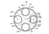
- FIG. 13is a plan view showing the vehicle-side resonance coil 110 when the vehicle-side resonance coil 110 and the facility-side resonance coil 240 are electromagnetically resonantly coupled.
- a broken lineschematically shows a near field having a high magnetic field strength.
- the near field NF1includes a unit near field UNF0 formed around the outer coil 115 and unit near fields UNF1 to UNF4 formed around the inner coils 111 to 114.
- the inner coils 111, 112, 113, 114are arranged at equal intervals around the winding center line O1, and are symmetrically arranged around the winding center line O1.
- the lengths of the coil wires constituting the inner coils 111, 112, 113, 114are substantially the same, and the outer coil 115 is also formed symmetrically around the winding center line O1.
- An end 131 ⁇ / b> A and an end 131 ⁇ / b> B of the vehicle-side resonance coil 110are formed in the inner coil 112.
- the wiring lengths of the connection wiring 132A and the connection wiring 132Bare substantially the same.
- the abdomen AM1 of the vehicle-side resonance coil 110is symmetric with the winding center line O1 with respect to the inner coil 112. Located on the inner coil 114.
- the abdomen AM1is located in the inner coil 114, and it can be seen that a near field having a higher magnetic field intensity is formed around the abdomen AM1 in a wider range than the other parts.
- the inner coil 114is located in a region surrounded by the outer coil 115. For this reason, even if a high-intensity magnetic field is formed around the abdominal part AM1, the high-intensity magnetic field can be prevented from spreading to a wide range outside the vehicle-side resonance coil 110.
- the end 131A and the end 131Bare located on the winding center line O1 side of the inner coil 112 with respect to the winding center line O112 of the inner coil 112.
- the abdominal part AM1is also located on the winding center line O1 side of the inner coil 114 with respect to the winding center line O114 of the inner coil 114. Thereby, it can suppress that the magnetic field with high intensity
- the abdominal part AM1is located in a portion of the inner coil 114 that is closest to the winding center line O1.
- FIG. 14is a perspective view schematically showing the equipment-side coil unit 201
- FIG. 15is a plan view of the equipment-side electromagnetic induction coil 230 and the equipment-side resonance coil 240 when viewed from the XV direction shown in FIG. is there.
- the equipment-side coil unit 201includes equipment-side resonance coils 240, equipment-side electromagnetic induction coils 230 arranged below the equipment-side resonance coils 240, and equipment-side resonance coils 240.
- the connected equipment side capacitor 250 and connection wirings 252A and 252B for connecting the equipment side capacitor 250 and the equipment side resonance coil 240are included.
- the facility-side resonance coil 240includes an end 251A and an end 251B.
- a connection wiring 252Ais connected to the end 251A, and a connection wiring 252B is connected to the end 251B.
- the connection wiring 252A and the connection wiring 252Bare also formed by bending the coil wire forming the equipment-side resonance coil 240 at the end portions of the end portion 251A and the end portion 251B.
- the facility-side resonance coil 240has substantially the same shape as the vehicle-side resonance coil 110.
- the facility-side resonance coil 240includes an outer coil 245, a plurality of inner coils 241, 242, 243, and 244 disposed inside the outer coil 245, and the outer coil 245 and the inner coils 241, 242, 243, and 244.
- the connecting connecting lines 246, 247, 248, 249are included.
- the winding center lines of the inner coils 241, 42, 243, and 244are arranged at equal intervals around the winding center line O2.
- the facility side resonance coil 240is also formed from one conducting wire, like the vehicle side resonance coil 110. For this reason, the installation side electromagnetic induction coil 230 etc. which transfer electric power between the installation side resonance coils 240 can be made into one, and the apparatus can be simplified.
- the equipment side electromagnetic induction coil 230when viewing the equipment side resonance coil 240 and the equipment side electromagnetic induction coil 230 in the direction of viewing the center point of the equipment side resonance coil 240 from the point on the winding center line O2, the equipment side electromagnetic induction coil 230 is It is formed so as to overlap with the outer coil 245. For this reason, transfer of the electric power between the installation side resonance coil 240 and the installation side electromagnetic induction coil 230 is performed efficiently.
- the outer coil 245includes arcuate arc portions 245a, 245b, 245c, and 245d that extend around the winding center line O2, and the arc portions 245a, 245b, 245c, 245d and the inner coils 241, 242, 243, 244 are connected.
- the connecting wires 246, 247, 248, and 249are formed so as to straddle a part of the equipment-side resonance coil 240 and bend so as to swell toward the equipment-side electromagnetic induction coil 230. is doing.
- the facility-side electromagnetic induction coil 230includes curved portions 231, 232, 233, and 234 that are curved in accordance with the shapes of the crossover wires 246, 247, 248, and 249, and the facility-side electromagnetic induction coil 230 and The occurrence of discharge between the equipment side resonance coil 240 is suppressed.
- the inner coils 241, 242, 243, 244are arranged symmetrically around the winding center line O2.
- an alternating current having a resonance frequencyflows through the equipment side resonance coil 240.
- the antinode of the alternating currentis located at the center portion in the length direction of the conductor forming the equipment-side resonance coil 240, the connection wiring 252A, the connection wiring 252B, and the equipment-side capacitor 250.
- the lengths of the two electrodes constituting the facility-side capacitor 250are substantially equal, and the wiring lengths of the connection wiring 252A and the connection wiring 252B are substantially equal.
- the antinode of the alternating currentis located at the center in the length direction of the coil wire forming the equipment-side resonance coil 240.
- the part which becomes an antinode of an alternating current among the installation side resonance coils 240is set to the abdominal part AM2.
- FIG. 16is a plan view of the equipment-side resonance coil 240 when a current having a resonance frequency flows through the equipment-side resonance coil 240.
- the broken line shown in FIG. 16is a figure which shows typically the area
- a near-field NF ⁇ b> 2is formed around the equipment-side resonance coil 240 when a current having a resonance frequency flows through the equipment-side resonance coil 240.
- the near field NF2includes a unit near field UNF10 formed around the outer coil 245 and unit near fields UNF11, UNF12, UNF13, UNF14 formed around the inner coils 241, 242, 243, 244.
- the abdomen AM2is located in the inner coil 244.
- the abdominal part AM2is located in a portion of the inner coil 244 that is closer to the winding center line O2 than the winding center line O244 of the inner coil 244.
- the vehicle-side resonance coil 110When charging the battery 150 mounted on the vehicle 100, the vehicle-side resonance coil 110 is positioned above the equipment-side resonance coil 240 as shown in FIG.
- FIG. 18is a plan view showing a positional relationship between the vehicle-side resonance coil 110 and the near field NF2 in a state where the vehicle-side resonance coil 110 and the facility-side resonance coil 240 are arranged in the vertical direction.
- the vehicle-side resonance coil 110is located in the near field NF2, and electric power is favorably transmitted from the equipment-side resonance coil 240 to the vehicle-side resonance coil 110.
- FIG. 19is a plan view showing a state in which the vehicle-side resonance coil 110 is displaced from the position of the vehicle-side resonance coil 110 shown in FIG.
- the vehicle-side resonance coil 110is displaced from the normal position.
- the vehicle-side resonance coil 110includes a plurality of inner coils 111, 112, 113, and 114 in plan view, the vehicle-side resonance coil 110 intersects the near field NF2 at many positions. Yes. For this reason, as shown in FIG. 19, even if the vehicle-side resonance coil 110 is displaced, power is transmitted to the vehicle-side resonance coil 110 from the equipment-side resonance coil 240, and reduction in power transmission efficiency is suppressed. Has been.
- the size of the vehicle-side resonance coil 110 itselfis suppressed from increasing.
- the vehicle side coil unit 101 and the facility side coil unit 201it is possible to prevent a high-intensity magnetic field from leaking to a wide range outside the resonance coils, and Even if the side resonance coil 110 and the equipment side resonance coil 240 are misaligned, it is possible to suppress a decrease in power transmission / reception efficiency.
- the inventors of the present applicationhave devised the mounting manner of the vehicle-side resonance coil 110 and the equipment-side resonance coil 240 to suppress leakage of a high-intensity magnetic field around the vehicle 100. This will be described with reference to the drawings.
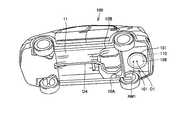
- FIG. 20is a perspective view showing the lower surface of the vehicle 100
- FIG. 21is a bottom view of the vehicle 100, showing a position where the vehicle-side resonance coil 110 is arranged.
- FIG. 22is a perspective view showing the floor panel 11 and the vehicle side coil unit 101 of the electric vehicle.
- the inner coil 114is located at the center in the width direction of the electric vehicle 100. Further, among the inner coils 111 to 114, the inner coil 114 is disposed at a position closest to the center point O4 of the electric vehicle 100. In other words, the vehicle-side resonance coil 110 is arranged such that the distance between the abdomen AM1 and the center point O4 of the vehicle 100 is smaller than the distance between the winding center line O1 and the center point O4. Yes.
- a region R1 and a region R2 illustrated in FIG. 21indicate regions having a strong magnetic field strength. Since the abdominal part AM1 is disposed at a position close to the center of the vehicle 100, the high-strength regions R1, R2 formed around the abdominal part AM1 are prevented from leaking around the vehicle 100.
- the abdomen AM1is disposed at the center in the width direction of the vehicle 100, and a high-intensity magnetic field formed around the abdomen AM1 can be prevented from leaking from the side surface side of the vehicle 100.
- the abdominal part AM1is located in a region surrounded by the outer coil 115, even if the vehicle-side resonance coil 110 is mounted on the electric vehicle 100 in a state where it is rotated from a predetermined position, a magnetic field having a high strength is generated. Leakage around electric vehicle 100 can be suppressed. For example, even if the vehicle-side resonance coil 110 is mounted with the vehicle-side resonance coil 110 rotated 90 ° from the state shown in FIG. 21, the distance between the abdominal part AM1 and the side surface of the electric vehicle 100 is secured. Further, it is possible to prevent the high-strength magnetic field from leaking from the side surface of the electric vehicle 100.
- the abdominal part AM1is disposed on the center line O5 that passes through the center part in the width direction of the vehicle 100 and extends in the front-rear direction of the vehicle 100, but is not limited to this position. It may be located around it.
- vehicle 100includes a pair of side members 10 ⁇ / b> A and 10 ⁇ / b> B arranged in the vehicle width direction, a pair of rear side members 10 ⁇ / b> C and 10 ⁇ / b> D arranged in the vehicle width direction, and floor panel 11. including.
- the floor panel 11is fixed to the upper surfaces of the side members 10A and 10B and the upper surfaces of the rear side members 10C and 10D.
- the vehicle side coil unit 101is provided on the lower surface of the floor panel 11.
- the rear side member 10Cis connected to the rear end of the side member 10A
- the rear side member 10Dis connected to the rear end of the side member 10B.
- the vehicle side coil unit 101 and the rear side members 10C and 10Dare viewed from above the vehicle side coil unit 101 and the rear side members 10C and 10D, the vehicle side coil unit 101 is disposed between the rear side member 10C and the rear side member 10D. ing.
- the vehicle side coil unit 101is disposed between the rear side member 10C and the rear side member 10D, and the rear side members 10C and 10D protrude from the lower surface of the floor panel 11, so that the rear side member The high-strength magnetic field is prevented from leaking to the outside by 10C and the rear side member 10D.
- the vehicle side coil unit 101by arranging the vehicle side coil unit 101 between the rear side members 10C and 10D, it is possible to protect the vehicle side coil unit 101 even if the vehicle 100 is subjected to a side collision.
- the vehicle-side resonance coil 110is disposed so that the abdomen AM1 is positioned between a pair of rear wheels arranged in the width direction, so that the magnetic field formed around the abdomen AM1 by the rear wheel is And the vehicle side coil unit 101 can be protected from an external impact.
- the wiring distance between the vehicle side coil unit 101 and the battery 150can be shortened.
- FIG. 23is a partial side view showing a state when the vehicle 100 stops at a predetermined position in the parking space 202.
- the parking space 202is provided with a wheel stop 203 that stops the rear wheel of the vehicle 100. By stopping the vehicle 100 so that the rear wheel hits the wheel stop 203, the vehicle 100 is stopped. Stops at a predetermined position in the parking space 202.
- the facility-side coil unit 201is provided at a position facing the vehicle-side coil unit 101 in the vertical direction.
- abdominal part AM1 and abdominal part AM2oppose each other in the height direction. For this reason, it is possible to suppress a high-strength magnetic field formed around the abdomen AM2 from leaking between the ground and the vehicle. Furthermore, by arranging the abdominal part AM1 and the abdominal part AM2 in the height direction, the degree of coupling between the vehicle-side resonance coil 110 and the facility-side resonance coil 240 can be increased, and the power transmission efficiency and the power reception efficiency can be increased.
- the abdominal part AM1is located in a region surrounded by the outer coil 115, and the abdominal part AM2 is located in a region surrounded by the outer coil 245, so that it is formed around the abdominal part AM2 during power transmission. It is possible to prevent a high-intensity magnetic field from leaking out between the vehicle and the ground. Furthermore, even if the vehicle-side resonance coil 110 and the equipment-side resonance coil 240 face each other in a relatively rotated state, the distance between the abdominal part AM1 and the abdominal part AM2 is short. The transmission efficiency between the coils 240 can be increased.
- the inner coil 114 where the abdominal part AM1 is positionedmay be provided so that the abdominal part AM1 is positioned within the region surrounded by the outer coil 115.
- vehicle-side capacitor 109is located on outer coil 115.
- the inner coil 114 positioned in the region surrounded by the outer coil 115is formed so that the abdomen AM1 is positioned in the region surrounded by the outer coil 115.
- the vehicle-side resonance coil 110is formed so that the abdomen AM1 is positioned on the inner coil 114.
- the inner coil 114is provided so that the abdominal part AM1 is located in a region surrounded by the outer coil 115.
- the vehicle-side resonance coil 110may be formed such that an extension portion extending toward the vehicle is formed, and the abdomen AM1 is positioned on the extension portion.
- the vehicle-side resonance coil 110When the inner coil 114 is formed in the vehicle-side resonance coil 110 as a means for positioning the abdominal part AM1 within the region surrounded by the outer coil 115, the vehicle-side resonance coil 110 and the equipment-side resonance coil 240 are relative to each other. Even if the position is shifted, it is possible to suppress a decrease in transmission efficiency.
- an extension portion extending from the outer coil 245 into a region surrounded by the outer coil 245is formed, and the abdomen AM2 is formed in the extension portion.
- the facility-side resonance coil 240may be formed so as to be positioned.
- the present inventioncan be applied to a coil unit, a power transmission device, an external power supply device, and a vehicle charging system.
Landscapes
- Engineering & Computer Science (AREA)
- Power Engineering (AREA)
- Computer Networks & Wireless Communication (AREA)
- Transportation (AREA)
- Mechanical Engineering (AREA)
- Signal Processing (AREA)
- Physics & Mathematics (AREA)
- Electromagnetism (AREA)
- Electric Propulsion And Braking For Vehicles (AREA)
- Current-Collector Devices For Electrically Propelled Vehicles (AREA)
- Charge And Discharge Circuits For Batteries Or The Like (AREA)
Abstract
Description
Translated fromJapanese本発明は、コイルユニット、送電装置、外部給電装置および車両充電システムに関する。The present invention relates to a coil unit, a power transmission device, an external power supply device, and a vehicle charging system.
近年、環境への配慮からバッテリなどの電力を用いて駆動輪を駆動させるハイブリッド車両や電気自動車などが着目されている。In recent years, attention has been paid to hybrid vehicles, electric vehicles, and the like that drive wheels using electric power such as batteries in consideration of the environment.
特に近年は、上記のようなバッテリを搭載した電動車両において、プラグなどを用いずに非接触でバッテリを充電可能なワイヤレス充電が着目されている。そして、最近では非接触の充電方式においても各種の充電方式が提案されており、特に、共鳴現象を利用することで非接触で電力を伝送する技術が脚光を浴びている。In particular, in recent years, attention has been paid to wireless charging capable of charging a battery in a contactless manner without using a plug or the like in an electric vehicle equipped with the battery as described above. Recently, various charging systems have been proposed for non-contact charging systems, and in particular, a technique for transmitting power in a non-contact manner by using a resonance phenomenon has been highlighted.
たとえば、特開2010-73976号公報に記載された車両および給電装置は、それぞれ通信コイルを備える。車両に搭載された通信コイルは、共鳴コイルと、受電コイルとを含み、給電装置に搭載された通信コイルは、共鳴コイルと給電コイルとを含む。そして、給電装置に搭載された共鳴コイルと、車両に搭載された共鳴コイルとの間で、共鳴現象を利用して電力の非接触伝送がなされている。For example, a vehicle and a power feeding device described in JP 2010-73976 A each include a communication coil. The communication coil mounted on the vehicle includes a resonance coil and a power receiving coil, and the communication coil mounted on the power feeding device includes a resonance coil and a power feeding coil. And the non-contact transmission of electric power is made | formed between the resonance coil mounted in the electric power feeder, and the resonance coil mounted in the vehicle using a resonance phenomenon.
特開2010-73976号公報に記載された車両および給電装置の間で非接触で電力伝送を行う際には、各共鳴コイル内に高電圧の高周波電流が流れ、各共鳴コイルの周囲には強度の高い磁場が形成される。この結果、電力伝送中に、車両の周囲に強度の高い磁場が漏れ出すおそれがある。When power is transmitted between a vehicle and a power feeding device described in JP 2010-73976 A without contact, a high-frequency high-frequency current flows in each resonance coil, and there is a strength around each resonance coil. A high magnetic field is formed. As a result, a high-intensity magnetic field may leak around the vehicle during power transmission.
本発明は、上記のような課題に鑑みてなされたものであって、その目的は、過度に強度の高い磁界がコイルユニットの周囲に漏れだすことが抑制されたコイルユニット、送電装置、外部給電装置および車両充電システムを提供することである。The present invention has been made in view of the above-described problems, and its object is to provide a coil unit, a power transmission device, and an external power supply in which an excessively strong magnetic field is prevented from leaking around the coil unit. An apparatus and a vehicle charging system are provided.
本発明に係る共鳴コイルは、外部に設けられた外部共鳴コイルと電磁界共振結合する共鳴コイルを備える。上記共鳴コイルは、第1巻回中心を中心として第1巻回中心の周囲を囲むように延びる外側コイルと、外側コイルから外側コイルで囲まれた領域内に延び出る延出部とを含む。上記外部共鳴コイルと共鳴コイルとが電磁界共振結合しているときに、共鳴コイルを流れる交流電流の腹となる部分を共鳴コイルの腹部とすると、共鳴コイルは、腹部が延出部に位置するように形成される。The resonance coil according to the present invention includes a resonance coil that is electromagnetically coupled to an external resonance coil provided outside. The resonance coil includes an outer coil that extends around the first winding center around the first winding center, and an extending portion that extends from the outer coil into a region surrounded by the outer coil. When the external resonance coil and the resonance coil are electromagnetically resonantly coupled, and the portion that becomes the antinode of the alternating current flowing through the resonance coil is the abdomen of the resonance coil, the resonance coil is located at the extension portion Formed as follows.
好ましくは、上記共鳴コイルは、環状に形成され、電流が流れることで形成される磁界の方向が外側コイルが形成する磁界の向きと同じ向きとされた内側コイルを含み、延出部は、内側コイルである。好ましくは、上記内側コイルは、外側コイルに沿って間隔をあけて複数設けられ、複数の内側コイルの1つに、腹部が位置する。Preferably, the resonance coil includes an inner coil that is formed in an annular shape, and the direction of the magnetic field formed by the flow of current is the same as the direction of the magnetic field formed by the outer coil. It is a coil. Preferably, a plurality of the inner coils are provided at intervals along the outer coil, and the abdomen is located in one of the plurality of inner coils.
好ましくは、上記内側コイルは、第2巻回中心の周囲を囲むように延びる。上記第2巻回中心は、第1巻回中心から離れた位置に位置する。上記共鳴コイルは、腹部が第2巻回中心よりも第1巻回中心側に位置するように形成される。好ましくは、上記共鳴コイルは、第1端部および第2端部を含む。上記第1端部および第2端部に接続されたキャパシタをさらに備る。上記腹部は、共鳴コイルを形成する導線の一端から他端までの長さ方向の中央部に位置する。Preferably, the inner coil extends so as to surround the periphery of the second winding center. The second winding center is located at a position away from the first winding center. The resonance coil is formed so that the abdomen is positioned closer to the first winding center than the second winding center. Preferably, the resonance coil includes a first end and a second end. A capacitor connected to the first end and the second end is further provided. The abdomen is located at the center in the length direction from one end to the other end of the conducting wire forming the resonance coil.
好ましくは、上記共鳴コイルは、環状に形成され、電流が流れることで形成される磁界の方向が外側コイルが形成する磁界の向きと同じ向きとされた内側コイルを含む。上記内側コイルは、外側コイルに沿って間隔をあけて複数設けられる。上記複数の内側コイルは、共鳴コイルの腹部が位置する第1内側コイルと、第1端部および第2端部を含み、キャパシタが接続された第2内側コイルとを含む。Preferably, the resonance coil includes an inner coil that is formed in an annular shape and in which the direction of the magnetic field formed by the flow of current is the same as the direction of the magnetic field formed by the outer coil. A plurality of the inner coils are provided at intervals along the outer coil. The plurality of inner coils include a first inner coil in which an abdomen of the resonance coil is located, and a second inner coil including a first end and a second end, and a capacitor connected thereto.
好ましくは、上記共鳴コイルとキャパシタとによって共振回路が形成される。上記記腹部は、共振回路の電流経路の中央に位置する。好ましくは、上記共鳴コイルと電磁誘導結合する電磁誘導コイルをさらに備える。本発明に係る車両は、上記コイルユニットを備え、共鳴コイルの腹部と車両の中心との間の距離は、第1巻回中心と車両の中心との間の距離よりも小さい。本発明に係る外部給電装置は、上記コイルユニットを備える。本発明に係る車両受電システムは、上記車両と、上記外部給電装置とを備える。Preferably, a resonance circuit is formed by the resonance coil and the capacitor. The abdomen is located at the center of the current path of the resonance circuit. Preferably, an electromagnetic induction coil that is electromagnetically coupled to the resonance coil is further provided. The vehicle according to the present invention includes the coil unit, and the distance between the abdomen of the resonance coil and the center of the vehicle is smaller than the distance between the first winding center and the center of the vehicle. The external electric power feeder which concerns on this invention is provided with the said coil unit. The vehicle power receiving system according to the present invention includes the vehicle and the external power feeding device.
本願発明に係るコイルユニット、送電装置、外部給電装置および車両充電システムによれば、過度に強度の高い磁界が周囲に漏れることを抑制することができる。According to the coil unit, the power transmission device, the external power supply device, and the vehicle charging system according to the present invention, it is possible to suppress an excessively strong magnetic field from leaking to the surroundings.
図1から図23を用いて、本発明の実施1の形態に係る車両および外部給電装置について説明する。1 to 23, a vehicle and an external power supply apparatus according to the first embodiment of the present invention will be described.
図1は、本実施の形態1の形態に係る車両100と、車両100に電力を給電する外部給電装置200とを模式的に示す模式図である。FIG. 1 is a schematic diagram schematically showing a
車両100は、外部給電装置200が設けられた駐車スペース202の所定位置に停車して、主に、外部給電装置200から電力を受電する。なお、車両100は、外部給電装置200に電力を供給することもできる。The
駐車スペース202には、車両100を所定の位置に停車するように、輪止203やラインが設けられている。In the
外部給電装置200は、交流電源210に接続された高周波電力ドライバ220と、この高周波電力ドライバ220に接続された設備側コイルユニット201とを含む。設備側コイルユニット201は、主に、非接触電力送電装置として機能し、設備側コイルユニット201は、設備側共鳴コイル240と、設備側共鳴コイル240に接続された設備側キャパシタ250と、設備側共鳴コイル240と電気的に接続される設備側電磁誘導コイル230とを含む。The external
交流電源210は、車両外部の電源であり、たとえば、系統電源である。高周波電力ドライバ220は、交流電源210から受け取る電力を高周波の電力に変換し、その変換した高周波電力を設備側電磁誘導コイル230に供給する。なお、高周波電力ドライバ220が生成する高周波電力の周波数は、たとえば1M~数十MHzである。
設備側電磁誘導コイル230は、上記の高周波電力が供給されることで、設備側電磁誘導コイル230から発生する磁束量が経時的に変化する。The facility-side
設備側共鳴コイル240は、設備側電磁誘導コイル230と電磁誘導結合しており、設備側共鳴コイル240からの磁束量が変化することで、電磁誘導により設備側共鳴コイル240にも高周波の電流が流れる。The facility-
この際、設備側共鳴コイル240に流れる高周波電流の周波数と、設備側電磁誘導コイル230のリラクタンスと設備側キャパシタ250の容量Cとによって決まる共振周波数とが実質的に一致するように、設備側電磁誘導コイル230に電流が供給される。設備側共鳴コイル240および設備側キャパシタ250は、LC共振器として機能する。At this time, the frequency of the high-frequency current flowing through the equipment-
そして、設備側共鳴コイル240の周囲に当該共振周波数と実質的に同じ周波数の電界および磁界が形成される。このようにして、設備側共鳴コイル240の周囲には、所定周波数の電磁場(電磁界)が形成される。Then, an electric field and a magnetic field having substantially the same frequency as the resonance frequency are formed around the equipment-
そして、車両100は、設備側共鳴コイル240および設備側キャパシタ250によって形成されたLC共振器と同じ共振周波数を持つLC共振器を備えており、当該LC共振器と、設備側共鳴コイル240および設備側キャパシタ250によって形成されたLC共振器とが電磁界共振結合することで、外部給電装置200から車両100に電力が送電される。The
なお、車両100と外部給電装置200とは、設備側共鳴コイル240および設備側キャパシタ250によって形成される電磁場のうち、近接場(エバネッセント場)を主に利用して、外部給電装置200側から車両100に電力を供給している。当該電磁共鳴法を利用したワイヤレス送電・受電方法の詳細については、後述する。Note that the
車両100は、主に非接触電力受電装置として機能する車両側コイルユニット101と、車両側コイルユニット101に接続された整流器130と、整流器130に接続されたDC/DCコンバータ140と、このDC/DCコンバータ140に接続されたバッテリ150と、パワーコントロールユニット(PCU(Power Control Unit))160と、このパワーコントロールユニット160に接続されたモータユニット170と、DC/DCコンバータ140やパワーコントロールユニット160などの駆動を制御する車両ECU(Electronic Control Unit)180とを備える。The
なお、本実施の形態に係る車両100は、図示しないエンジンを備えたハイブリッド車両であるが、モータにより駆動される車両であれば、電気自動車や燃料電池車両も含む。Note that the
車両側コイルユニット101は、車両側共鳴コイル110と、この車両側共鳴コイル110に接続された車両側キャパシタ109と、車両側共鳴コイル110と電磁誘導により結合する車両側電磁誘導コイル120とを含む。なお、車両側コイルユニット101の詳細な構成については後述する。The vehicle
車両側共鳴コイル110と車両側キャパシタ109は、LC共振器を構成しており、車両側共鳴コイル110および車両側キャパシタ109によって形成されたLC共振器の共振周波数と、設備側共鳴コイル240および設備側キャパシタ250によって形成されたLC共振器の共振周波数とは実質的に一致している。The vehicle-
ここで設備側共鳴コイル240に、当該LC共振器の共振周波数と同じ周波数の高周波電流が供給されると、周波数が当該共振周波数の電磁場(電磁界)が発生する。Here, when a high-frequency current having the same frequency as the resonance frequency of the LC resonator is supplied to the facility-
そして、設備側共鳴コイル240から、たとえば、数m以内程度の範囲内に、車両側共鳴コイル110が配置されると、車両側共鳴コイル110および車両側キャパシタ109によって形成されるLC共振器が共鳴して、車両側共鳴コイル110に電流が流れる。このように、車両側共鳴コイル110と、設備側共鳴コイル240とは、電磁界共振結合する。When the vehicle-
車両側電磁誘導コイル120は、車両側共鳴コイル110と電磁誘導結合して、車両側共鳴コイル110が受電した電力を取り出す。車両側電磁誘導コイル120が車両側共鳴コイル110から順次電力を取り出すことで、電磁場を介して車両側共鳴コイル110に設備側共鳴コイル240から順次電力が供給される。このように、車両側コイルユニット101と、設備側コイルユニット201とは、所謂、電磁共鳴方式のワイヤレス送電・受電方式が採用されている。The vehicle-side
整流器130は、車両側電磁誘導コイル120に接続されており、車両側電磁誘導コイル120から供給される交流電流を直流電流に変換して、DC/DCコンバータ140に供給する。The
DC/DCコンバータ140は、整流器130から供給された直流電流の電圧を調整して、バッテリ150に供給する。The DC /
パワーコントロールユニット160は、バッテリ150に接続されたコンバータと、このコンバータに接続されたインバータとを含み、コンバータは、バッテリ150から供給される直流電流を調整(昇圧)して、インバータに供給する。インバータは、コンバータから供給される直流電流を交流電流に変換して、モータユニット170に供給する。The
モータユニット170は、たとえば、三相交流モータなどが採用されており、パワーコントロールユニット160のインバータから供給される交流電流によって駆動する。The
なお、バッテリ150に蓄積された電力を交流電源210に供給する際には、たとえば、DC/DCコンバータ140がバッテリ150からの電流を昇圧して、整流器130に供給する。整流器130は、DC/DCコンバータ140からの直流電流を高周波電流に変換する。この高周波電流の周波数は、上記の共振周波数とされている。When supplying the electric power stored in the
整流器130は、この高周波電流を車両側電磁誘導コイル120に供給する。車両側共鳴コイル110は、電磁誘導によって車両側電磁誘導コイル120から高周波電流を受け取る。この高周波電流の周波数は、共振周波数と実質的に一致しており、車両側共鳴コイル110および車両側キャパシタ109によって形成されたLC共振器が共振する。そして、車両側共鳴コイル110の周囲に周波数が上記共振周波数とされた電磁場(電磁界)が形成される。The
そして、車両側共鳴コイル110から、たとえば、数m程度の範囲内に設備側共鳴コイル240が配置されることで、設備側共鳴コイル240および設備側キャパシタ250によって形成されるLC共振器が共鳴する。そして、設備側共鳴コイル240に供給された電力は、電磁誘導によって設備側電磁誘導コイル230に引き出される。設備側共鳴コイル240に引き出された電力は、高周波電力ドライバ220を通って、交流電源210に供給される。And the LC resonator formed by the equipment
なお、車両100がハイブリッド車両の場合には、車両100は、エンジン、動力分割機構とをさらに備え、モータユニット170は、発電機として主に機能するモータジェネレータと、電動機として主に機能するモータジェネレータとを含む。When
上記のように本実施の形態1に係る車両側コイルユニット101と設備側コイルユニット201との間は、ワイヤレス送電・受電方式であって、電磁場を利用した共鳴法が採用されている。As described above, between the vehicle-
図2は、共鳴法による送電および受電の原理を説明するための模式図であって、この図2を用いて、共鳴法による送電および受電の原理を説明する。FIG. 2 is a schematic diagram for explaining the principle of power transmission and power reception by the resonance method. The principle of power transmission and power reception by the resonance method will be described with reference to FIG.
図2を参照して、この共鳴法では、2つの音叉が共鳴するのと同様に、同じ固有振動数を有する2つのLC共振コイルが電磁場(近接場)において共鳴することによって、一方のコイルから他方のコイルへ電磁場を介して電力が伝送される。Referring to FIG. 2, in this resonance method, in the same way as two tuning forks resonate, two LC resonance coils having the same natural frequency resonate in an electromagnetic field (near field), and thereby, from one coil. Electric power is transmitted to the other coil via an electromagnetic field.
具体的には、高周波電源310に一次コイル320を接続し、電磁誘導により一次コイル320と磁気的に結合される一次自己共振コイル330へ、1M~数十MHzの高周波電力を給電する。一次自己共振コイル330は、コイル自身のインダクタンスと浮遊容量(コイルにコンデンサが接続される場合には、コンデンサの容量を含む)とによるLC共振器であり、一次自己共振コイル330と同じ共振周波数を有する二次自己共振コイル340と電磁場(近接場)を介して共鳴する。そうすると、一次自己共振コイル330から二次自己共振コイル340へ電磁場を介してエネルギー(電力)が移動する。二次自己共振コイル340へ移動したエネルギー(電力)は、電磁誘導により二次自己共振コイル340と磁気的に結合される二次コイル350によって取出され、負荷360へ供給される。なお、共鳴法による送電は、一次自己共振コイル330と二次自己共振コイル340との共鳴強度を示すQ値がたとえば100よりも大きいときに実現される。Specifically, the
なお、図2の構成と図1の構成の対応関係を示すと、図1に示す交流電源210および高周波電力ドライバ220は、図2の高周波電源310に相当する。また、図1に示す設備側電磁誘導コイル230は、図2の一次コイル320に相当する。さらに、図1に示す設備側共鳴コイル240および設備側キャパシタ250は、図3の一次自己共振コイル330および一次自己共振コイル330の浮遊容量とに相当する。2 shows the correspondence relationship between the configuration of FIG. 2 and the configuration of FIG. 1, the
図1に示す車両側共鳴コイル110および車両側キャパシタ109は、図2に示す二次自己共振コイル340および二次自己共振コイル340の浮遊容量とに相当する。1 corresponds to the stray capacitance of the secondary self-
図1に示す車両側電磁誘導コイル120は、図2の二次コイル350に相当する。そして、図1に示す整流器130、DC/DCコンバータ140およびバッテリ150は、図2に示す負荷360に相当する。The vehicle-side
さらに、本実施の形態1に係るワイヤレス送電・受電方式は、電磁界の「静電界」が支配的な近接場(エバネッセント場)を利用することで、送電および受電効率の向上が図られている。Furthermore, the wireless power transmission / reception method according to the first embodiment uses a near field (evanescent field) in which the “electrostatic field” of the electromagnetic field is dominant to improve power transmission and power reception efficiency. .
図3は、電流源(磁流源)からの距離と電磁界の強度との関係を示した図である。図3を参照して、電磁界は3つの成分から成る。曲線k1は、波源からの距離に反比例した成分であり、「輻射電界」と称される。曲線k2は、波源からの距離の2乗に反比例した成分であり、「誘導電界」と称される。また、曲線k3は、波源からの距離の3乗に反比例した成分であり、「静電界」と称される。FIG. 3 is a diagram showing the relationship between the distance from the current source (magnetic current source) and the strength of the electromagnetic field. Referring to FIG. 3, the electromagnetic field is composed of three components. A curve k1 is a component inversely proportional to the distance from the wave source, and is referred to as a “radiating electric field”. A curve k2 is a component inversely proportional to the square of the distance from the wave source, and is referred to as an “induced electric field”. The curve k3 is a component that is inversely proportional to the cube of the distance from the wave source, and is referred to as an “electrostatic field”.
「静電界」は、波源からの距離とともに急激に電磁波の強度が減少する領域であり、共鳴法では、この「静電界」が支配的な近接場(エバネッセント場)を利用してエネルギー(電力)の伝送が行なわれる。すなわち、「静電界」が支配的な近接場において、同じ固有振動数を有する一対の共鳴器(たとえば一対のLC共振コイル)を共鳴させることにより、一方の共鳴器(一次自己共振コイル)から他方の共鳴器(二次自己共振コイル)へエネルギー(電力)を伝送する。この「静電界」は遠方にエネルギーを伝播しないので、遠方までエネルギーを伝播する「輻射電界」によってエネルギー(電力)を伝送する電磁波に比べて、共鳴法は、より少ないエネルギー損失で送電することができる。The “electrostatic field” is a region where the intensity of the electromagnetic wave suddenly decreases with the distance from the wave source. In the resonance method, energy (electric power) is utilized using the near field (evanescent field) in which this “electrostatic field” is dominant. Is transmitted. That is, by resonating a pair of resonators having the same natural frequency (for example, a pair of LC resonance coils) in a near field where the “electrostatic field” is dominant, the resonance from one resonator (primary self-resonance coil) to the other Energy (electric power) is transmitted to the resonator (secondary self-resonant coil). Since this “electrostatic field” does not propagate energy far away, the resonance method can transmit power with less energy loss than electromagnetic waves that transmit energy (electric power) by “radiant electric field” that propagates energy far away. it can.
このように、本実施の形態1に係る車両100と、外部給電装置200とは、電磁場の近接場の共鳴を利用して、車両100の車両側コイルユニット101と、外部給電装置200の設備側コイルユニット201との間で電力の送電や受電を行っている。As described above, the
ここで、車両側コイルユニット101と設備側コイルユニット201との間で電力の送電および受電を行っている際に、車両の周囲に強度の高い磁界が漏れ出すと、車両100の周囲の電気機器などに影響を与えるおそれがある。Here, when a high-intensity magnetic field leaks around the vehicle while power is being transmitted and received between the vehicle-
本願の発明者等は、鋭意努力の結果、受電および送電の過程において、車両側共鳴コイル110の特定の部位および設備側共鳴コイル240の特定の部位の周囲に特に強度の高い磁場が形成されることを見出した、本願発明においては、受電および送電の過程において、車両100の周囲に強い磁場が漏れ出すことを抑制することを目的としており、以下にその具体的な構成について説明する。As a result of earnest efforts, the inventors of the present application form a particularly strong magnetic field around a specific part of the vehicle-
図4は、車両に搭載された車両側コイルユニット101を模式的に示す斜視図である。この図4に示すように、車両側コイルユニット101は、車両側共鳴コイル110と、車両側電磁誘導コイル120と、車両側共鳴コイル110に接続された車両側キャパシタ109と、車両側キャパシタ109および車両側共鳴コイル110を接続する接続配線132Aおよび接続配線132Bとを含む。FIG. 4 is a perspective view schematically showing the vehicle-
車両側共鳴コイル110は、端部131Aおよび端部131Bとを含み、端部131Aには、接続配線132Aが接続されており、端部131Bには接続配線132Bが接続されている。この接続配線132Aおよび接続配線132Bによって車両側キャパシタ109と、車両側共鳴コイル110とが直列に接続されている。なお、この図4に示す例においては、接続配線132A,132Bと、車両側共鳴コイル110とは一体的に形成されている。具体的には、車両側共鳴コイル110を構成するコイル線を端部131A,131Bで屈曲させて接続配線132A,132Bを形成している。The vehicle-
図5は、図4に示すV方向から車両側共鳴コイル110および車両側電磁誘導コイル120を見た平面図である。なお、図5において、車両側電磁誘導コイル120は、破線で示されている。この図5および図4に示すように、車両側共鳴コイル110は、車両側電磁誘導コイル120の下方に配置されている。車両側共鳴コイル110は、巻回中心線O1の周囲を囲むように延びる外側コイル115と、この外側コイル115に接続され、
外側コイル115が取り囲む領域内に配置された複数の内側コイル111,112,113,114と、複数の渡り線116、117,118,119とを含む。FIG. 5 is a plan view of the vehicle-
A plurality of
外側コイル115と、車両側電磁誘導コイル120とは、巻回中心線O1上に位置する位置から外側コイル115の中心点を見る方向に、外側コイル115および車両側電磁誘導コイル120を見ると、外側コイル115と車両側電磁誘導コイル120とは重なり合う。When the
すなわち、外側コイル115および車両側電磁誘導コイル120は、互いに一方が他方に沿うように形成されている。That is, the
ここで、車両側共鳴コイル110と車両側電磁誘導コイル120との間で電流の授受は電磁誘導によって行われる。Here, current exchange between the vehicle-
外側コイル115と車両側電磁誘導コイル120とは重なり合うように配置されているため、車両側共鳴コイル110と車両側電磁誘導コイル120との間で電流の授受が行われる際、車両側共鳴コイル110に電流が流れることで生じる磁力線の多くが車両側電磁誘導コイル120を通る。これにより、車両側電磁誘導コイル120に大きな起電力が生じ、車両側共鳴コイル110と車両側電磁誘導コイル120との間で電流の授受が良好に行われる。Since the
外側コイル115は、巻回中心線O1の周囲に沿って延びるように形成されている。内側コイル111,112,113,114は、互いに外側コイル115の周方向に間隔をあけて配置されている。内側コイル111,112,113,114は、巻回中心線O1の周囲に環状に配列しており、各内側コイル111,112,113,114の巻回中心は、巻回中心線O1の周囲に等間隔に配置されている。内側コイル111,112,113,114は、外側コイル115の内周縁部に内接するように配置されている。このため、内側コイル111,112,113,114の各径を大きく確保することができ、受電および送電効率の向上を図ることができる。The
内側コイル112には、車両側共鳴コイル110の端部131A,131Bが位置しており、内側コイル112に車両側キャパシタ109が接続されている。End portions 131 </ b> A and 131 </ b> B of the vehicle-
車両側共鳴コイル110は、1つの導線から形成されており、外側コイル115、内側コイル111,112,113,114および渡り線116、117,118,119は、1つの導線から一体的に形成されている。The vehicle-
車両側共鳴コイル110を1つの導線で構成することで、車両側共鳴コイル110との間で電力の授受を行う車両側電磁誘導コイル120を1つに集約することができ、部品点数の低減を図ることができる。なお、外側コイル115および内側コイル111,112,113,114は、1巻のコイルであり、車両側共鳴コイル110のコンパクト化が図られている。By configuring the vehicle-
図6は、車両側共鳴コイル110を詳細に説明するための分解図であり、車両側共鳴コイル110を構成する構成要素ごとに車両側共鳴コイル110を切断したときの分解図である。FIG. 6 is an exploded view for explaining the vehicle
この図6に示すように、外側コイル115は、複数の円弧部115a~115dを含む。各円弧部115a~115dは、図4,5に示す巻回中心線O1を中心に円弧状に延びるように形成されている。As shown in FIG. 6, the
なお、外側コイル115の形状としては、円形形状に限られず、方形形状、多角形形状、楕円形状など各種形状を採用することができる。It should be noted that the shape of the
内側コイル111,112,113,114も略円形形状とされているが、円形形状に限られず、方形形状、多角形形状、楕円形状など各種形状を採用することができる。なお、内側コイル111,112,113,114の各中心線は、巻回中心線O1から離れており、巻回中心線O1を中心に配列している。The
渡り線116、117,118,119は、内側コイル111,112,113,114と円弧部115a,115b、115c、115dとを接続する。
渡り線116は、円弧部115aの一端と内側コイル111の一端とを接続し、円弧部115aの他方端は、内側コイル112の一端に接続されている。The connecting
渡り線117は、内側コイル112の他方端と円弧部115bの一端とを接続し、円弧部115bの他方端は内側コイル113の一端に接続されている。渡り線118は、内側コイル113の他方端と円弧部115cの一端とを接続し、円弧部115cの他方端は内側コイル114の一端に接続されている。渡り線119は、内側コイル114の他方端と円弧部115dの一端とを接続する。円弧部115dの他方端は、内側コイル111の他方端に接続されている。The connecting
なお、図6は、車両側共鳴コイル110を説明するために便宜的に車両側共鳴コイル110を分解した状態を示しているが、車両側共鳴コイル110は1つの導線によって形成されている。FIG. 6 shows a state in which the vehicle-
図7は、渡り線116およびその周囲の構成を示す斜視図である。この図7および図4に示すように、渡り線116は、車両側共鳴コイル110の一部である内側コイル111を跨ぐように形成されてる。FIG. 7 is a perspective view showing the
渡り線116は、車両側電磁誘導コイル120側に向けて膨らむように湾曲している。なお、他の渡り線117、118,119も、車両側電磁誘導コイル120と同様に形成されており、各々車両側共鳴コイル110の一部を跨ぐように形成されている。The connecting
この際、渡り線116、117,118,119と、車両側共鳴コイル110の一部との間の距離L2は、たとえば、車両側共鳴コイル110を構成する導線の直径よりも大きく設定されており、渡り線116、117,118,119と車両側共鳴コイル110との間で放電が生じることが抑制されている。At this time, the distance L2 between the
図8は、車両側共鳴コイル110および車両側電磁誘導コイル120の一部を示す側面図である。この図8に示すように、車両側電磁誘導コイル120は、渡り線116に沿って延びる湾曲部121を含む。FIG. 8 is a side view showing a part of the vehicle
湾曲部121と渡り線116との間の距離L1が車両側電磁誘導コイル120のうち湾曲部121以外の部分と車両側共鳴コイル110との間の距離と等しくなるように、湾曲部121は湾曲している。The bending
図4に示すように、車両側電磁誘導コイル120は、車両側共鳴コイル110の渡り線117,118、119に沿って延びる湾曲部122,123,124を含む。As shown in FIG. 4, the vehicle-side
これにより、車両側電磁誘導コイル120と車両側共鳴コイル110とは、互いに全周に亘って、互いの距離が一定距離L1となるように形成されている。Thereby, the vehicle-side
このように、車両側共鳴コイル110と車両側電磁誘導コイル120との間の距離が短くなる部分がないため、車両側共鳴コイル110および車両側電磁誘導コイル120に高電圧の電流が流れたとしても、車両側共鳴コイル110および車両側電磁誘導コイル120の間で放電が生じることを抑制することができる。As described above, since there is no portion where the distance between the vehicle-
さらに、車両側電磁誘導コイル120および車両側共鳴コイル110の間の距離を一定間隔に保つことで、車両側共鳴コイル110に良好に起電力を発生させることができ、車両側共鳴コイル110および車両側電磁誘導コイル120の間での電力の授受を良好に行うことができる。Furthermore, by keeping the distance between the vehicle-side
図9は、車両側共鳴コイル110に電流が流れたときの状態を示す模式図である。この図9に示すように、車両側共鳴コイル110に電流が流れると、外側コイル115には、電流方向D0に電流が流れる。内側コイル111,112,113,114には、電流方向D1,D2,D3,D4に電流が流れる。FIG. 9 is a schematic diagram showing a state when a current flows through the vehicle-
外側コイル115、および内側コイル111,112,113,114に上記のような方向に電流が流れると、外側コイル115および内側コイル111,112,113,114によって磁界が発生する。この際、外側コイル115および内側コイル111,112,113,114によって発生する磁界の向きはいずれも同じ方向に向くように、外側コイル115および内側コイル111,112,113,114は巻かれている。When a current flows through the
図10は、上記のように構成された車両側共鳴コイル110および車両側キャパシタ109を模式的に示す回路図である。この図10において、車両側キャパシタ109は、互いに対向する電極134および電極135を含み、接続配線132Aおよび接続配線132Bによって、電極134,135が車両側共鳴コイル110の各端部131A,131Bに接続されている。FIG. 10 is a circuit diagram schematically showing the vehicle-
設備側共鳴コイル240と車両側共鳴コイル110とが電磁界結合(電磁共鳴)する際には、車両側共鳴コイル110、車両側キャパシタ109および接続配線112,113によって形成される電流経路内に高周波の交流電流が流れる。この交流電流の周波数は、LC共振回路の共振周波数と実質的に一致しており、当該交流電流は共振状態となっている。図11は、車両側共鳴コイル110、車両側キャパシタ109および接続配線132A,113によって形成されたLC共振器の展開図および共振回路内を流れる電流値を示すグラフである。When the facility-
この図11において、電極134の端部を共振回路の回路始点LOとし、電極135の端部を共振回路の回路終端LEとする。In FIG. 11, the end of the
図11に示す縦軸は、電流量を示し、横軸は、共振回路の位置を示す。そして、曲線CL1は、電磁界共振結合しているときの任意の時点における電流量の分布を示す。そして、曲線CL2~CL7は、曲線CL1の時点から時々刻々変化する電流量の分布を示す。The vertical axis shown in FIG. 11 indicates the amount of current, and the horizontal axis indicates the position of the resonance circuit. A curve CL1 shows the distribution of the current amount at an arbitrary time when the electromagnetic resonance coupling is performed. Curves CL2 to CL7 show the distribution of current amount that changes every moment from the time point of the curve CL1.
この曲線CL1~CL7からも明らかなように、共振回路内を流れる電流は、中間位置LM1の部分が「腹」となる。なお、接続配線132Aおよび電極134の結線位置と回路始点LOとの間の距離と、電極135および接続配線132Bの結線位置と回路終端LEとの間の距離は、実質的に等しい。また、接続配線132Aの長さと、接続配線132Bの長さとは等しい。このため、中間位置LM1は、車両側共鳴コイル110を形成する導線の長さ方向の中央に位置している。このような共振交流電流においては、「腹」(anti-node)の部分で電流量が最大となる。そこで、車両側共鳴コイル110のうち、共振交流電流の「腹」となる部分を腹部AM1とする。As is clear from the curves CL1 to CL7, the current flowing in the resonance circuit has a “belly” portion at the intermediate position LM1. The distance between the connection position of the
車両側共鳴コイル110の腹部AM1を流れる電流が最大となるため、腹部AM1の周囲で強度の高い磁界が発生する。そして、車両側共鳴コイル110の端部側に向かうにつれて、車両側共鳴コイル110の周囲に形成される磁界の強度が小さくなる。Since the current flowing through the abdominal part AM1 of the vehicle
その一方で、回路始点LOおよび回路終端LEにおける電位は高く、腹部AM1における電位は低いため、電界強度は回路始点LOおよび回路終端LEの周囲で大きくなり、車両側共鳴コイル110の腹部AM1の周囲で最小となる。On the other hand, since the potential at the circuit start point LO and the circuit end LE is high and the potential at the abdomen AM1 is low, the electric field strength increases around the circuit start point LO and the circuit end LE. The minimum.
図12は、共振回路の位置とその位置の周囲に形成される電界強度EFおよび磁界強度MFを模式的に示すグラフである。この図12からも明らかなように、車両側共鳴コイル110の腹部AM1の周囲に強度の高い磁場が形成されることが分かる。FIG. 12 is a graph schematically showing the position of the resonance circuit and the electric field strength EF and magnetic field strength MF formed around the position. As is apparent from FIG. 12, a high-intensity magnetic field is formed around the abdomen AM1 of the vehicle-
なお、図11から図12においては、車両側共鳴コイル110を含む共振回路について説明したが、設備側共鳴コイル240、設備側キャパシタ250および接続配線によって形成されたLC共振回路においても、車両側共鳴コイル110を含むLC共振回路と同様の電流分布、磁界強度分布および電界強度分布となる。11 to 12, the resonance circuit including the vehicle-
図13は、車両側共鳴コイル110と、設備側共鳴コイル240とが電磁界共振結合しているときにおける車両側共鳴コイル110を示す平面図である。なお、この図13において、破線は、磁界の強度の高い近接場を模式的に示す。FIG. 13 is a plan view showing the vehicle-
車両側共鳴コイル110と設備側共鳴コイル240とが電磁界共振結合すると、車両側共鳴コイル110には、周波数が共振周波数の交流電流が流れる。これにより、車両側共鳴コイル110の周囲には、近接場NF1が形成される。近接場NF1は、外側コイル115の周囲に形成された単位近接場UNF0と、各内側コイル111~114の周囲に形成された単位近接場UNF1~UNF4とを含む。When the vehicle-
内側コイル111,112,113,114は、巻回中心線O1の周囲に等間隔に配置されると共に、互いに巻回中心線O1を中心に対称的に配置されている。内側コイル111,112,113,114を構成するコイル線の長さはいずれも実質的に一致しており、外側コイル115も、巻回中心線O1を中心に対称的に形成されている。内側コイル112に車両側共鳴コイル110の端部131Aおよび端部131Bが形成されている。さらに、接続配線132Aおよび接続配線132Bの配線長さは、実質的に一致している。The
そして、車両側共鳴コイル110の端部131Bおよび接続配線132Aが内側コイル112に形成されているため、車両側共鳴コイル110の腹部AM1は、内側コイル112に対して巻回中心線O1と対称な内側コイル114に位置する。そして、腹部AM1は、内側コイル114に位置しており、腹部AM1の周囲には、他の部分よりも広い範囲で磁界の強度が高い近接場が形成されていることがわかる。Since the
内側コイル114は、外側コイル115によって囲まれる領域内に位置している。このため、腹部AM1の周囲に強度の高い磁場が形成されたとしても、この強度の高い磁界が車両側共鳴コイル110の外側の広い範囲にまで広がることを抑制することができる。端部131Aおよび端部131Bは、内側コイル112のうち、内側コイル112の巻回中心線O112よりも、巻回中心線O1側に位置している。このため、腹部AM1も内側コイル114のうち、内側コイル114の巻回中心線O114よりも、巻回中心線O1側に位置している。これにより、腹部AM1の周囲に形成される強度の高い磁界が、車両側共鳴コイル110より外側の広い範囲まで広がることを抑制することができる。The
図13などに示す例においては、腹部AM1は、内側コイル114のうち、最も巻回中心線O1に近接した部分に位置している。In the example shown in FIG. 13 and the like, the abdominal part AM1 is located in a portion of the
図14は、設備側コイルユニット201を模式的に示す斜視図であり、図15は、図14に示すXV方向から設備側電磁誘導コイル230および設備側共鳴コイル240を見たときの平面図である。14 is a perspective view schematically showing the equipment-
図14および図15に示すように、設備側コイルユニット201は、設備側共鳴コイル240と、この設備側共鳴コイル240の下方に配置された設備側電磁誘導コイル230と、設備側共鳴コイル240に接続された設備側キャパシタ250と、設備側キャパシタ250および設備側共鳴コイル240を接続する接続配線252A,252Bとを含む。As shown in FIGS. 14 and 15, the equipment-
設備側共鳴コイル240は、端部251Aおよび端部251Bを含む。端部251Aには、接続配線252Aが接続され、端部251Bには接続配線252Bが接続されている。なお、接続配線252Aおよび接続配線252Bも、設備側共鳴コイル240を形成するコイル線を端部251Aおよび端部251Bの端部で折り曲げることで形成されている。The facility-
設備側共鳴コイル240は、車両側共鳴コイル110と実質的に同一の形状とされている。設備側共鳴コイル240は、外側コイル245と、この外側コイル245の内側に配置された複数の内側コイル241,242,243,244と、外側コイル245および各内側コイル241,242,243,244を接続する渡り線246,247,248,249を含む。内側コイル241,42,243,244の各巻回中心線は、巻回中心線O2の周囲に等間隔に配置されている。The facility-
なお、設備側共鳴コイル240も、車両側共鳴コイル110と同様に1つの導線から形成されている。このため、設備側共鳴コイル240との間で電力の授受を行う設備側電磁誘導コイル230などを1つにすることができ、装置の簡略化を図ることができる。In addition, the facility
図15において、巻回中心線O2上の点から設備側共鳴コイル240の中心点を見る方向で、設備側共鳴コイル240および設備側電磁誘導コイル230を見ると、設備側電磁誘導コイル230は、外側コイル245と重なり合うように形成されている。このため、設備側共鳴コイル240と設備側電磁誘導コイル230との間の電力の授受が効率的に行われる。In FIG. 15, when viewing the equipment
図15において、外側コイル245は、巻回中心線O2を中心に延びる円弧状の円弧部245a,245b、245c、245dを含み、渡り線246,247,248,249によって、円弧部245a,245b、245c、245dと内側コイル241,242,243,244とが接続されている。In FIG. 15, the
この図15に示す例においても、渡り線246,247,248,249は、設備側共鳴コイル240の一部を跨ぐように形成されており、設備側電磁誘導コイル230に向けて膨らむように湾曲している。Also in the example shown in FIG. 15, the connecting
図14に示すように、設備側電磁誘導コイル230は、渡り線246,247,248,249の形状に合わせて湾曲する湾曲部231,232,233,234を含み、設備側電磁誘導コイル230および設備側共鳴コイル240との間で放電が生じることが抑制されている。As shown in FIG. 14, the facility-side
さらに、設備側電磁誘導コイル230と設備側共鳴コイル240との間の距離を一定にすることで、設備側電磁誘導コイル230に良好に起電力を発生させることができ、設備側電磁誘導コイル230と設備側共鳴コイル240との間の電力の授受効率の向上が図られている。Further, by making the distance between the facility-side
図15において、外側コイル245に電流方向D10に電流が流れる際には、内側コイル241,242,243,244には、電流方向D11,D12,D13,D14に電流が流れる。このため、外側コイル245によって形成される磁界の方向と、各内側コイル241,242,243,244によって形成される磁界の方向とは一致する。15, when a current flows through the
内側コイル241,242,243,244は、巻回中心線O2を中心に対称的に配置されている。そして、設備側コイルユニット201から車両側コイルユニット101に電力を送電する際には、設備側共鳴コイル240には周波数が共振周波数の交流電流が流れる。The
この際、設備側共鳴コイル240と、接続配線252Aと、接続配線252Bと、設備側キャパシタ250とを形成する導線の長さ方向の中央部に、上記交流電流の腹が位置する。設備側キャパシタ250を構成する2つの電極の長さが実質的等しく、さらに、接続配線252Aおよび接続配線252Bの配線長さが実質的に等しい。このため、上記交流電流の腹は、設備側共鳴コイル240を形成するコイル線の長さ方向の中央部に位置する。そして、設備側共鳴コイル240のうち、交流電流の腹となる部分を腹部AM2とする。At this time, the antinode of the alternating current is located at the center portion in the length direction of the conductor forming the equipment-
図16は、設備側共鳴コイル240に共振周波数の電流が流れたときにおける設備側共鳴コイル240の平面図である。なお、図16に示す破線は、設備側共鳴コイル240の周囲に形成される近接場のうち、磁界の強度が高い領域を模式的に示す図である。FIG. 16 is a plan view of the equipment-
設備側共鳴コイル240に共振周波数の電流が流れることで、設備側共鳴コイル240の周囲に近接場NF2が形成される。近接場NF2は、外側コイル245の周囲に形成される単位近接場UNF10と、各内側コイル241,242,243,244の周囲に形成される単位近接場UNF11,UNF12,UNF13,UNF14を含む。A near-field NF <b> 2 is formed around the equipment-
腹部AM2の周囲には、他の部分よりも広い範囲で、強度の高い磁界が形成されていることがわかる。腹部AM2は、内側コイル244に位置している。具体的には、腹部AM2は、内側コイル244のうち、内側コイル244の巻回中心線O244よりも、巻回中心線O2に近い部分に位置している。It can be seen that a strong magnetic field is formed around the abdomen AM2 in a wider range than the other parts. The abdomen AM2 is located in the
このため、腹部AM2の周囲に形成される強度の高い磁界が、設備側共鳴コイル240の外側において広い範囲に広がることを抑制することができる。For this reason, it is possible to prevent a high-intensity magnetic field formed around the abdominal part AM2 from spreading over a wide range outside the facility-
車両100に搭載されたバッテリ150を充電する際には、図17に示すように、車両側共鳴コイル110は、設備側共鳴コイル240の上方に位置する。When charging the
そして、設備側共鳴コイル240に共振周波数の高周波電流が流れる。そして、図16に示すように、近接場NF2が設備側共鳴コイル240の周囲に形成される。Then, a high-frequency current having a resonance frequency flows through the facility-
図18は、車両側共鳴コイル110と設備側共鳴コイル240とが鉛直方向に配列した状態において、車両側共鳴コイル110と近接場NF2との位置関係を示す平面図である。FIG. 18 is a plan view showing a positional relationship between the vehicle-
この図18に示す状態においては、車両側共鳴コイル110は、近接場NF2内に位置しており、設備側共鳴コイル240から車両側共鳴コイル110に良好に電力が伝達される。In the state shown in FIG. 18, the vehicle-
図19は、図18に示す車両側共鳴コイル110の位置から車両側共鳴コイル110が位置ずれした状態を示す平面図である。FIG. 19 is a plan view showing a state in which the vehicle-
この図19においては、図18に示すように、車両側共鳴コイル110が正常な位置から位置ずれしている。その一方で、平面視すると、車両側共鳴コイル110は、複数の内側コイル111,112,113,114を備えているため、車両側共鳴コイル110は、近接場NF2と多数の位置で交差している。このため、この図19に示すように、車両側共鳴コイル110が位置ずれしたとしても、車両側共鳴コイル110には、設備側共鳴コイル240から電力が伝達され、電力の伝達効率の低減が抑制されている。In FIG. 19, as shown in FIG. 18, the vehicle-
さらに、複数の内側コイル111,112,113,114が外側コイル115の内側に配置されているため、車両側共鳴コイル110自体の大きさが大きくなることが抑制されている。Furthermore, since the plurality of
このように、本実施の形態に係る車両側コイルユニット101および設備側コイルユニット201によれば、強度の高い磁界が各共鳴コイルの外側の広い範囲に漏れることを抑制することができるとともに、車両側共鳴コイル110および設備側共鳴コイル240とが位置ずれしたとしても、送電・受電効率の低下を抑制することができる。As described above, according to the vehicle
次に、本願発明者等は、車両側共鳴コイル110および設備側共鳴コイル240の搭載態様を工夫することで、強度の高い磁場が車両100の周囲に漏れることを抑制しており、その詳細について図を用いて説明する。Next, the inventors of the present application have devised the mounting manner of the vehicle-
図20は、車両100の下面を示す斜視図であり、図21は、車両100の底面図であって、車両側共鳴コイル110の配置位置を示す底面図である。そして、図22は、電動車両のフロアパネル11や車両側コイルユニット101を示す斜視図である。FIG. 20 is a perspective view showing the lower surface of the
図20および図21において、内側コイル114は、電動車両100の幅方向の中央部に位置している。さらに、内側コイル111~114のうち、内側コイル114が最も、電動車両100の中心点O4に近い位置に配置されている。換言すれば、車両側共鳴コイル110は、腹部AM1と車両100の中心点O4との間の距離が、巻回中心線O1と中心点O4との間の距離よりも小さくなるように配置されている。図21に示す領域R1および領域R2は、磁界の強度の強い領域を示す。腹部AM1が車両100の中心に近い位置に配置されているため、腹部AM1の周囲に形成される強度の高い領域R1,R2が車両100の周囲に漏れることが抑制されている。20 and 21, the
腹部AM1は、車両100の幅方向の中央部に配置されており、腹部AM1の周囲に形成される強度の高い磁場が車両100の側面側から漏れることを抑制することができる。The abdomen AM1 is disposed at the center in the width direction of the
さらに、腹部AM1は、外側コイル115によって囲まれる領域内に位置しているため、車両側共鳴コイル110が所定の位置から回転した状態で電動車両100に搭載されたとしても、強度が高い磁界が電動車両100の周囲に漏れることを抑制することができる。たとえば、図21に示す状態から車両側共鳴コイル110を90°回転した状態で車両側共鳴コイル110が搭載されたとしても、腹部AM1と電動車両100の側面との間の距離は確保されており、強度の高い磁界が電動車両100の側面からもれることが抑制されている。Furthermore, since the abdominal part AM1 is located in a region surrounded by the
図21に示す例においては、腹部AM1は、車両100の幅方向中央部をとおり車両100の前後方向に延びる中心線O5上に配置されているが、この位置に限られず、中心線O5上およびその周囲に位置してもよい。In the example shown in FIG. 21, the abdominal part AM1 is disposed on the center line O5 that passes through the center part in the width direction of the
図20から図22を参照して、車両100は、車両の幅方向に配列する一対のサイドメンバ10A,10Bと、車両の幅方向に配列する一対のリヤサイドメンバ10C,10Dと、フロアパネル11とを含む。フロアパネル11は、サイドメンバ10A,10Bの上面と、リヤサイドメンバ10C,10Dとの上面に固定されている。車両側コイルユニット101は、フロアパネル11の下面に設けられている。Referring to FIGS. 20 to 22,
図21および図22に示すように、リヤサイドメンバ10Cは、サイドメンバ10Aの後端に接続され、リヤサイドメンバ10Dは、サイドメンバ10Bの後端に接続されている。車両側コイルユニット101と、リヤサイドメンバ10C,10Dとの上方から車両側コイルユニット101とリヤサイドメンバ10C,10Dを見ると、車両側コイルユニット101は、リヤサイドメンバ10Cおよびリヤサイドメンバ10Dの間に配置されている。21 and 22, the
また、図22に示すように、車両側コイルユニット101は、リヤサイドメンバ10Cおよびリヤサイドメンバ10D間に配置されており、リヤサイドメンバ10C,10Dは、フロアパネル11の下面から突出しているため、リヤサイドメンバ10C,リヤサイドメンバ10Dによって強度の高い磁場が外部に漏れることが抑制されている。As shown in FIG. 22, the vehicle
さらに、車両側コイルユニット101をリヤサイドメンバ10C,10Dの間に配置することで、車両100が側突されたとしても車両側コイルユニット101の保護を図ることができる。特に、好ましくは、腹部AM1が、幅方向に配列する一対の後輪の間に位置するように車両側共鳴コイル110を配置することで、後輪によって腹部AM1の周囲に形成される磁場が車両の周囲に漏れることが抑制されると共に外部からの衝撃から車両側コイルユニット101を保護することができる。Furthermore, by arranging the vehicle
バッテリ150は、フロアパネル11のうち、リヤサイドメンバ10Cおよびリヤサイドメンバ10Dの間に配置されているため、車両側コイルユニット101とバッテリ150との配線距離を短くすることができる。Since the
次に、外部給電装置200の設備側コイルユニット201について詳細に説明する。図23は、車両100が駐車スペース202の所定位置に停車したときの様子を示す一部側面図である。Next, the equipment
この図23に示すように、駐車スペース202には、車両100の後輪を止める輪止203が設けられており、後輪が輪止203とあたるように車両100を停車することで、車両100は、駐車スペース202の所定位置に停車する。As shown in FIG. 23, the
車両100が、駐車スペース202の所定位置に停車すると、設備側コイルユニット201は、車両側コイルユニット101と鉛直方向に対向する位置に設けられている。When the
そして、図17に示すように、腹部AM1および腹部AM2は、互いに高さ方向に対向する。このため、腹部AM2の周囲に形成される強度の高い磁界が地面と車両の間から外部に漏れることを抑制することができる。さらに、腹部AM1と腹部AM2とが高さ方向に配列することで、車両側共鳴コイル110および設備側共鳴コイル240の結合度を高めることができ、送電効率および受電効率を高めることができる。And as shown in FIG. 17, abdominal part AM1 and abdominal part AM2 oppose each other in the height direction. For this reason, it is possible to suppress a high-strength magnetic field formed around the abdomen AM2 from leaking between the ground and the vehicle. Furthermore, by arranging the abdominal part AM1 and the abdominal part AM2 in the height direction, the degree of coupling between the vehicle-
特に、腹部AM1は、外側コイル115によって囲まれる領域内に位置しており、腹部AM2は、外側コイル245によって囲まれる領域内に位置しているため、電力伝送時に、腹部AM2の周囲に形成される強度の高い磁界が車両と地面の間から外部に漏れ出すことが抑制されている。さらに、車両側共鳴コイル110および設備側共鳴コイル240とが互いに相対的に回転した状態で対向したとしても、腹部AM1および腹部AM2の間の距離が短いため、車両側共鳴コイル110および設備側共鳴コイル240の間の伝送効率を高くすることができる。In particular, the abdominal part AM1 is located in a region surrounded by the
なお、本実施の形態に係る車両側共鳴コイル110は、腹部AM1が位置する内側コイル114以外にも複数の内側コイル111~113が設けられているが、これら内側コイル111~113は必ずしも必須の構成ではない。The vehicle-
すなわち、腹部AM1が、外側コイル115によって囲まれる領域内に位置するように、腹部AM1が位置する内側コイル114のみを設けるようにしてもよい。この場合、典型的には、車両側キャパシタ109は、外側コイル115上に位置する。That is, only the
なお、設備側共鳴コイル240においても、同様に、腹部AM2が位置する内側コイル244以外の内側コイル241~243は必ずしも必須の構成ではない。In the facility-
内側コイル111~113や内側コイル241~243を設けることで、上述のように、車両側共鳴コイル110および設備側共鳴コイル240が相対的に位置ずれしたとしても、互いに重なり合う部分を増やすこおができ、伝送効率の低下を抑制することができる。By providing the
上記実施の形態においては、腹部AM1が外側コイル115によって囲まれる領域内に位置するように、外側コイル115によって囲まれる領域内に位置する内側コイル114を形成している。そして、車両側共鳴コイル110は、腹部AM1が内側コイル114に位置するように形成されている。In the above embodiment, the
このように、上記実施の形態においては、腹部AM1が外側コイル115によって囲まれる領域内に位置するように、内側コイル114が設けられている。Thus, in the above-described embodiment, the
しかし、腹部AM1を外側コイル115によって囲まれる領域内に配置するための手段として、内側コイルのように環状のコイルを形成することは必須ではなく、外側コイル115から外側コイル115によって囲まれる領域内に向けて延び出る延出部を形成し、この延出部上に腹部AM1が位置するように車両側共鳴コイル110を形成するようにしてもよい。However, as a means for arranging the abdominal part AM1 in the region surrounded by the
なお、腹部AM1を外側コイル115によって囲まれる領域内に位置させる手段として、車両側共鳴コイル110に内側コイル114を形成した場合には、車両側共鳴コイル110と設備側共鳴コイル240とが相対的に位置ずれしたとしても、伝送効率の低下を抑制することができる。When the
なお、設備側共鳴コイル240においても、同様に、内側コイルを設けずに、外側コイル245から外側コイル245によって囲まれる領域内に延び出る延出部を形成し、この延出部に腹部AM2が位置するように設備側共鳴コイル240を形成してもよい。Similarly, in the facility-
以上のように本発明の実施の形態について説明を行なったが、今回開示された実施の形態はすべての点で例示であって制限的なものではないと考えられるべきである。本発明の範囲は請求の範囲によって示され、請求の範囲と均等の意味および範囲内でのすべての変更が含まれることが意図される。さらに、上記数値などは、例示であり、上記数値および範囲にかぎられない。As described above, the embodiment of the present invention has been described. However, the embodiment disclosed this time should be considered as illustrative in all points and not restrictive. The scope of the present invention is defined by the terms of the claims, and is intended to include any modifications within the scope and meaning equivalent to the terms of the claims. Furthermore, the above numerical values are examples, and are not limited to the above numerical values and ranges.
本発明は、コイルユニット、送電装置、外部給電装置および車両充電システムに適用することができる。The present invention can be applied to a coil unit, a power transmission device, an external power supply device, and a vehicle charging system.
10A,10B サイドメンバ、10C,10D,10C,10D リヤサイドメンバ、11 フロアパネル、100 車両、101 車両側コイルユニット、109 車両側キャパシタ、110 車両側共鳴コイル、111,112,113,114,241,242,243,244 内側コイル、115,245 外側コイル、120 車両側電磁誘導コイル、130 整流器、131A,131A,251A,251B 端部、134,134 電極、140 コンバータ、150 バッテリ、160 パワーコントロールユニット、170 モータユニット、200 外部給電装置、201 設備側コイルユニット、202 駐車スペース、203 輪止、210 交流電源、220 高周波電力ドライバ、230 設備側電磁誘導コイル、240 設備側共鳴コイル、250 設備側キャパシタ、AM1,AM2 腹部、C 容量、O1,O2,O112,O114,O244 巻回中心線、O4 中心点、O5 中心線。10A, 10B side member, 10C, 10D, 10C, 10D rear side member, 11 floor panel, 100 vehicle, 101 vehicle side coil unit, 109 vehicle side capacitor, 110 vehicle side resonance coil, 111, 112, 113, 114, 241, 242,243,244 inner coil, 115,245 outer coil, 120 vehicle side electromagnetic induction coil, 130 rectifier, 131A, 131A, 251A, 251B end, 134, 134 electrodes, 140 converter, 150 battery, 160 power control unit, 170 motor unit, 200 external power supply device, 201 equipment side coil unit, 202 parking space, 203 wheel stop, 210 AC power supply, 220 high frequency power driver, 230 equipment side electromagnetic induction Coil, 240 equipment-side resonance coil, 250 equipment-side capacitor, AM1, AM2 abdomen, C capacitance, O1, O2, O112, O114, O244 spirally wound center line, O4 center point, O5 centerline.
Claims (11)
Translated fromJapanese前記共鳴コイル(110)は、第1巻回中心(O1)を中心として前記第1巻回中心(O1)の周囲を囲むように延びる外側コイル(115)と、前記外側コイル(115)から前記外側コイル(115)で囲まれた領域内に延出する延出部とを含み、
前記外部共鳴コイル(240)と前記共鳴コイル(110)とが電磁界共振結合しているときに、前記共鳴コイル(110)を流れる交流電流の腹となる部分を共鳴コイル(110)の腹部とすると、前記共鳴コイル(110)は、前記腹部(AM1)が前記延出部(114)に位置するように形成された、コイルユニット。An external resonance coil (240) provided outside and a resonance coil (110) that is electromagnetically resonantly coupled;
The resonance coil (110) includes an outer coil (115) extending around the first winding center (O1) around the first winding center (O1), and the outer coil (115) from the outer coil (115). An extension portion extending into a region surrounded by the outer coil (115),
When the external resonance coil (240) and the resonance coil (110) are electromagnetically resonantly coupled, a portion serving as an antinode of an alternating current flowing through the resonance coil (110) is defined as an abdomen of the resonance coil (110). Then, the resonance coil (110) is a coil unit formed so that the abdomen (AM1) is located at the extension (114).
前記延出部は、前記内側コイル(114)である、請求項1に記載のコイルユニット。The resonance coil (110) includes an inner coil (114) that is formed in an annular shape and has a magnetic field formed by a current flowing in the same direction as the magnetic field formed by the outer coil (115). ,
The coil unit according to claim 1, wherein the extending portion is the inner coil (114).
複数の前記内側コイルの1つに、前記腹部(AM1)が位置する、請求項2に記載のコイルユニット。A plurality of the inner coils are provided at intervals along the outer coil,
The coil unit according to claim 2, wherein the abdomen (AM1) is located in one of the plurality of inner coils.
前記第2巻回中心(O114)は、前記第1巻回中心(O1)から離れた位置に位置し、
前記共鳴コイル(110)は、前記腹部(AM1)が前記第2巻回中心(O114)よりも前記第1巻回中心(O1)側に位置するように形成された、請求項2に記載のコイルユニット。The inner coil (114) extends so as to surround the second winding center (O114),
The second winding center (O114) is located at a position away from the first winding center (O1),
The said resonance coil (110) is formed so that the said abdomen (AM1) may be located in the said 1st winding center (O1) side rather than the said 2nd winding center (O114). Coil unit.
前記第1端部および第2端部に接続されたキャパシタをさらに備え、
前記腹部(AM1)は、前記共鳴コイル(110)を形成する導線の一端から他端までの長さ方向の中央部に位置する、請求項1に記載のコイルユニット。The resonant coil (110) includes a first end and a second end,
A capacitor connected to the first end and the second end;
The said abdomen (AM1) is a coil unit of Claim 1 located in the center part of the length direction from the one end of the conducting wire which forms the said resonance coil (110) to the other end.
前記内側コイルは、前記外側コイルに沿って間隔をあけて複数設けられ、
複数の前記内側コイルは、前記共鳴コイル(110)の腹部(AM1)が位置する第1内側コイル(114)と、前記第1端部および第2端部を含み、前記キャパシタが接続された第2内側コイル(109)とを含む、請求項5に記載のコイルユニット。The resonance coil (110) includes an inner coil (114) that is formed in an annular shape and has a magnetic field formed by a current flowing in the same direction as the magnetic field formed by the outer coil (115). ,
A plurality of the inner coils are provided at intervals along the outer coil,
The plurality of inner coils include a first inner coil (114) where an abdomen (AM1) of the resonance coil (110) is located, a first end and a second end, and the capacitor is connected to the first coil The coil unit according to claim 5, comprising two inner coils (109).
前記腹部(AM1)は、前記共振回路の電流経路の中央に位置する、請求項5に記載のコイルユニット。A resonance circuit is formed by the resonance coil (110) and the capacitor.
The coil unit according to claim 5, wherein the abdomen (AM1) is located at a center of a current path of the resonance circuit.
前記共鳴コイル(110)の腹部(AM1)と前記車両の中心との間の距離は、前記第1巻回中心(O1)と前記車両の中心との間の距離よりも小さい、車両。A vehicle comprising the coil unit according to any one of claims 1 to 8,
The vehicle, wherein a distance between the abdomen (AM1) of the resonance coil (110) and the center of the vehicle is smaller than a distance between the first winding center (O1) and the center of the vehicle.
請求項10に記載の外部給電装置と、
を備えた車両給電システム。A vehicle according to claim 9;
An external power supply device according to claim 10,
Vehicle power supply system with
Priority Applications (5)
| Application Number | Priority Date | Filing Date | Title |
|---|---|---|---|
| JP2013504426AJP5510608B2 (en) | 2011-03-11 | 2011-03-11 | Coil unit, vehicle, external power supply device, and vehicle charging system |
| US13/983,662US9124126B2 (en) | 2011-03-11 | 2011-03-11 | Coil unit, power transmission device, external power feeding apparatus, and vehicle charging system |
| CN2011800692153ACN103430258A (en) | 2011-03-11 | 2011-03-11 | Coil unit, power transmission device, external power supply device, and vehicle charging system |
| PCT/JP2011/055813WO2012124029A1 (en) | 2011-03-11 | 2011-03-11 | Coil unit, power transmission device, external power supply device, and vehicle charging system |
| EP20110861133EP2685478A4 (en) | 2011-03-11 | 2011-03-11 | SPOOL UNIT, POWER SUPPLY TRANSMISSION DEVICE, EXTERNAL POWER SUPPLY DEVICE, AND VEHICLE LOADING SYSTEM |
Applications Claiming Priority (1)
| Application Number | Priority Date | Filing Date | Title |
|---|---|---|---|
| PCT/JP2011/055813WO2012124029A1 (en) | 2011-03-11 | 2011-03-11 | Coil unit, power transmission device, external power supply device, and vehicle charging system |
Publications (1)
| Publication Number | Publication Date |
|---|---|
| WO2012124029A1true WO2012124029A1 (en) | 2012-09-20 |
Family
ID=46830165
Family Applications (1)
| Application Number | Title | Priority Date | Filing Date |
|---|---|---|---|
| PCT/JP2011/055813CeasedWO2012124029A1 (en) | 2011-03-11 | 2011-03-11 | Coil unit, power transmission device, external power supply device, and vehicle charging system |
Country Status (5)
| Country | Link |
|---|---|
| US (1) | US9124126B2 (en) |
| EP (1) | EP2685478A4 (en) |
| JP (1) | JP5510608B2 (en) |
| CN (1) | CN103430258A (en) |
| WO (1) | WO2012124029A1 (en) |
Cited By (3)
| Publication number | Priority date | Publication date | Assignee | Title |
|---|---|---|---|---|
| WO2015137431A1 (en)* | 2014-03-14 | 2015-09-17 | 株式会社村田製作所 | Power receiving coil structure and wireless power feeding system |
| EP2787595A3 (en)* | 2013-04-03 | 2016-04-27 | Funai Electric Co., Ltd. | Non-contact communication coil, non-contact power feeding device, and non-contact power receiving device |
| US9908424B2 (en) | 2014-11-13 | 2018-03-06 | Hyundai Motor Company | Wireless charging system |
Families Citing this family (28)
| Publication number | Priority date | Publication date | Assignee | Title |
|---|---|---|---|---|
| JP5718619B2 (en)* | 2010-11-18 | 2015-05-13 | トヨタ自動車株式会社 | Coil unit, contactless power transmission device, vehicle, and contactless power supply system |
| US9030053B2 (en)* | 2011-05-19 | 2015-05-12 | Choon Sae Lee | Device for collecting energy wirelessly |
| KR101697418B1 (en)* | 2012-05-09 | 2017-01-17 | 도요타지도샤가부시키가이샤 | Vehicle |
| JP2013243431A (en)* | 2012-05-17 | 2013-12-05 | Equos Research Co Ltd | Antenna coil |
| JP6160083B2 (en)* | 2013-01-08 | 2017-07-12 | 株式会社Ihi | Foreign object detection device |
| US9586493B2 (en)* | 2013-02-27 | 2017-03-07 | Satyajit Patwardhan | Hands free conductive charging system for electric vehicles |
| KR20150056421A (en)* | 2013-11-15 | 2015-05-26 | 현대자동차주식회사 | Transmitter apparatus of wireless power transmission system |
| CN103746466B (en)* | 2014-01-21 | 2015-10-21 | 清华大学 | A kind of magnet coupled resonant type wireless power transfer being applicable to multi-load transmission |
| US10461582B2 (en)* | 2014-03-31 | 2019-10-29 | Qualcomm Incorporated | Systems, apparatus, and methods for wireless power receiver coil configuration |
| US10044232B2 (en) | 2014-04-04 | 2018-08-07 | Apple Inc. | Inductive power transfer using acoustic or haptic devices |
| CN103904750B (en)* | 2014-04-09 | 2017-02-15 | 凌广 | Automatic charging system of electric automobile |
| US10083792B2 (en) | 2014-05-14 | 2018-09-25 | Qualcomm Incorporated | System, method and apparatus for reducing the height of bipolar transmitters and/or receivers in electric vehicle charging |
| US10135303B2 (en) | 2014-05-19 | 2018-11-20 | Apple Inc. | Operating a wireless power transfer system at multiple frequencies |
| KR101535048B1 (en) | 2014-09-30 | 2015-07-09 | 엘지이노텍 주식회사 | Wireless apparatus for transmitting power |
| JP6502056B2 (en)* | 2014-10-22 | 2019-04-17 | 日本圧着端子製造株式会社 | Electrical connection device |
| US20160211064A1 (en)* | 2015-01-19 | 2016-07-21 | Industry-Academic Cooperation Foundation Chosun University | Wireless power charging apparatus using superconducting coil |
| GB2535464A (en)* | 2015-02-16 | 2016-08-24 | Bombardier Transp Gmbh | Winding structure of a system for inductive power transfer, method of operating a winding structure and system of inductive power transfer |
| US11569138B2 (en)* | 2015-06-16 | 2023-01-31 | Kla Corporation | System and method for monitoring parameters of a semiconductor factory automation system |
| EP3338340B1 (en) | 2015-09-24 | 2020-06-17 | Apple Inc. | Configurable wireless transmitter device |
| US10790699B2 (en) | 2015-09-24 | 2020-09-29 | Apple Inc. | Configurable wireless transmitter device |
| US10477741B1 (en) | 2015-09-29 | 2019-11-12 | Apple Inc. | Communication enabled EMF shield enclosures |
| US10651685B1 (en) | 2015-09-30 | 2020-05-12 | Apple Inc. | Selective activation of a wireless transmitter device |
| US20170155285A1 (en)* | 2015-11-30 | 2017-06-01 | Electronics And Telecommunications Research Institute | Open type resonance coil without dual loops having serial type in-phase direct power feeding method without dual loops |
| US10714960B2 (en)* | 2015-12-22 | 2020-07-14 | Intel Corporation | Uniform wireless charging device |
| FI128674B (en)* | 2016-02-04 | 2020-10-15 | Rolls Royce Oy Ab | Apparatus for transferring electrical energy |
| US10734840B2 (en) | 2016-08-26 | 2020-08-04 | Apple Inc. | Shared power converter for a wireless transmitter device |
| US10594160B2 (en)* | 2017-01-11 | 2020-03-17 | Apple Inc. | Noise mitigation in wireless power systems |
| US11451093B2 (en)* | 2017-09-05 | 2022-09-20 | University Of Florida Research Foundation, Incorporated | Wireless power transfer to biomedical implants |
Citations (2)
| Publication number | Priority date | Publication date | Assignee | Title |
|---|---|---|---|---|
| JP2010073976A (en) | 2008-09-19 | 2010-04-02 | Yazaki Corp | Communication coil structure of wireless power transmission device |
| WO2010064584A1 (en)* | 2008-12-01 | 2010-06-10 | 株式会社 豊田自動織機 | Non-contact power transmission apparatus and design method |
Family Cites Families (13)
| Publication number | Priority date | Publication date | Assignee | Title |
|---|---|---|---|---|
| US7825543B2 (en) | 2005-07-12 | 2010-11-02 | Massachusetts Institute Of Technology | Wireless energy transfer |
| CN101860089B (en) | 2005-07-12 | 2013-02-06 | 麻省理工学院 | wireless non-radiative energy transfer |
| KR20110117732A (en) | 2007-03-27 | 2011-10-27 | 메사추세츠 인스티튜트 오브 테크놀로지 | Wireless energy transfer |
| JP5353376B2 (en)* | 2009-03-31 | 2013-11-27 | 富士通株式会社 | Wireless power device and wireless power receiving method |
| JP5359544B2 (en)* | 2009-05-18 | 2013-12-04 | トヨタ自動車株式会社 | Non-contact power transmission device, vehicle and non-contact power transmission system |
| US8674550B2 (en)* | 2010-03-25 | 2014-03-18 | General Electric Company | Contactless power transfer system and method |
| JP5718619B2 (en) | 2010-11-18 | 2015-05-13 | トヨタ自動車株式会社 | Coil unit, contactless power transmission device, vehicle, and contactless power supply system |
| US8575252B2 (en)* | 2011-02-09 | 2013-11-05 | Equistar Chemicals, Lp | Controlled rheology formulations containing high melt strength polypropylene for extrusion coating |
| EP2676827B1 (en) | 2011-02-15 | 2019-03-27 | Toyota Jidosha Kabushiki Kaisha | Vehicle and external power supply device |
| JP5710313B2 (en)* | 2011-02-25 | 2015-04-30 | トヨタ自動車株式会社 | Resonance coil, power transmission device, power reception device, and power transmission system |
| JP2012222956A (en)* | 2011-04-08 | 2012-11-12 | Toyota Motor Corp | Vehicle-side coil unit, equipment-side coil unit, and power transmission system |
| KR20140067134A (en)* | 2011-09-21 | 2014-06-03 | 도요타지도샤가부시키가이샤 | Contactless power transmission device, contactless power receiving device and contactless power transceiver system |
| EP2768116A4 (en)* | 2011-10-12 | 2015-09-02 | Toyota Motor Co Ltd | POWER TRANSMISSION APPARATUS AND SYSTEM AND POWER RECEPTION APPARATUS |
- 2011
- 2011-03-11WOPCT/JP2011/055813patent/WO2012124029A1/ennot_activeCeased
- 2011-03-11USUS13/983,662patent/US9124126B2/ennot_activeExpired - Fee Related
- 2011-03-11CNCN2011800692153Apatent/CN103430258A/enactivePending
- 2011-03-11JPJP2013504426Apatent/JP5510608B2/enactiveActive
- 2011-03-11EPEP20110861133patent/EP2685478A4/ennot_activeWithdrawn
Patent Citations (2)
| Publication number | Priority date | Publication date | Assignee | Title |
|---|---|---|---|---|
| JP2010073976A (en) | 2008-09-19 | 2010-04-02 | Yazaki Corp | Communication coil structure of wireless power transmission device |
| WO2010064584A1 (en)* | 2008-12-01 | 2010-06-10 | 株式会社 豊田自動織機 | Non-contact power transmission apparatus and design method |
Non-Patent Citations (1)
| Title |
|---|
| See also references ofEP2685478A4 |
Cited By (5)
| Publication number | Priority date | Publication date | Assignee | Title |
|---|---|---|---|---|
| EP2787595A3 (en)* | 2013-04-03 | 2016-04-27 | Funai Electric Co., Ltd. | Non-contact communication coil, non-contact power feeding device, and non-contact power receiving device |
| US9812254B2 (en) | 2013-04-03 | 2017-11-07 | Funai Electric Co., Ltd. | Wireless power feeder |
| WO2015137431A1 (en)* | 2014-03-14 | 2015-09-17 | 株式会社村田製作所 | Power receiving coil structure and wireless power feeding system |
| JPWO2015137431A1 (en)* | 2014-03-14 | 2017-04-06 | 株式会社村田製作所 | Power receiving coil structure and wireless power feeding system |
| US9908424B2 (en) | 2014-11-13 | 2018-03-06 | Hyundai Motor Company | Wireless charging system |
Also Published As
| Publication number | Publication date |
|---|---|
| EP2685478A4 (en) | 2014-09-10 |
| EP2685478A1 (en) | 2014-01-15 |
| JP5510608B2 (en) | 2014-06-04 |
| CN103430258A (en) | 2013-12-04 |
| JPWO2012124029A1 (en) | 2014-07-17 |
| US20130335018A1 (en) | 2013-12-19 |
| US9124126B2 (en) | 2015-09-01 |
Similar Documents
| Publication | Publication Date | Title |
|---|---|---|
| JP5510608B2 (en) | Coil unit, vehicle, external power supply device, and vehicle charging system | |
| JP5718619B2 (en) | Coil unit, contactless power transmission device, vehicle, and contactless power supply system | |
| JP5077340B2 (en) | Non-contact power receiving apparatus and manufacturing method thereof | |
| JP5776703B2 (en) | Vehicle and external power supply device | |
| CN103038089B (en) | Coil unit, non-contact power transmitting device, noncontact power receiving apparatus, vehicle and contactless power supply system | |
| JP5016069B2 (en) | Power transmission system and vehicle power supply device | |
| JP4962621B2 (en) | Non-contact power transmission device and vehicle equipped with non-contact power transmission device | |
| WO2013001636A1 (en) | Power transmitting device, power receiving device, and power transmission system | |
| JP2010098807A (en) | Noncontact power supply system | |
| JPWO2010038297A1 (en) | Self-resonant coil, non-contact power transmission device and vehicle | |
| JP5549748B2 (en) | Vehicle and external power supply device | |
| JP5625263B2 (en) | Coil unit, non-contact power transmission device, non-contact power supply system, and electric vehicle | |
| JP5710313B2 (en) | Resonance coil, power transmission device, power reception device, and power transmission system | |
| CN105765825B (en) | Power receiving device and power transmission device | |
| JPWO2013001636A1 (en) | Power transmission device, power reception device, and power transmission system |
Legal Events
| Date | Code | Title | Description |
|---|---|---|---|
| 121 | Ep: the epo has been informed by wipo that ep was designated in this application | Ref document number:11861133 Country of ref document:EP Kind code of ref document:A1 | |
| WWE | Wipo information: entry into national phase | Ref document number:13983662 Country of ref document:US | |
| ENP | Entry into the national phase | Ref document number:2013504426 Country of ref document:JP Kind code of ref document:A | |
| NENP | Non-entry into the national phase | Ref country code:DE | |
| REEP | Request for entry into the european phase | Ref document number:2011861133 Country of ref document:EP | |
| WWE | Wipo information: entry into national phase | Ref document number:2011861133 Country of ref document:EP |