WO2012105158A1 - Electronic device - Google Patents
Electronic deviceDownload PDFInfo
- Publication number
- WO2012105158A1 WO2012105158A1PCT/JP2012/000039JP2012000039WWO2012105158A1WO 2012105158 A1WO2012105158 A1WO 2012105158A1JP 2012000039 WJP2012000039 WJP 2012000039WWO 2012105158 A1WO2012105158 A1WO 2012105158A1
- Authority
- WO
- WIPO (PCT)
- Prior art keywords
- user
- electronic device
- touch panel
- area
- key
- Prior art date
Links
Images


Classifications
- G—PHYSICS
- G06—COMPUTING OR CALCULATING; COUNTING
- G06F—ELECTRIC DIGITAL DATA PROCESSING
- G06F3/00—Input arrangements for transferring data to be processed into a form capable of being handled by the computer; Output arrangements for transferring data from processing unit to output unit, e.g. interface arrangements
- G06F3/01—Input arrangements or combined input and output arrangements for interaction between user and computer
- G06F3/016—Input arrangements with force or tactile feedback as computer generated output to the user
- G—PHYSICS
- G06—COMPUTING OR CALCULATING; COUNTING
- G06F—ELECTRIC DIGITAL DATA PROCESSING
- G06F3/00—Input arrangements for transferring data to be processed into a form capable of being handled by the computer; Output arrangements for transferring data from processing unit to output unit, e.g. interface arrangements
- G06F3/01—Input arrangements or combined input and output arrangements for interaction between user and computer
- G06F3/048—Interaction techniques based on graphical user interfaces [GUI]
- G06F3/0487—Interaction techniques based on graphical user interfaces [GUI] using specific features provided by the input device, e.g. functions controlled by the rotation of a mouse with dual sensing arrangements, or of the nature of the input device, e.g. tap gestures based on pressure sensed by a digitiser
- G06F3/0488—Interaction techniques based on graphical user interfaces [GUI] using specific features provided by the input device, e.g. functions controlled by the rotation of a mouse with dual sensing arrangements, or of the nature of the input device, e.g. tap gestures based on pressure sensed by a digitiser using a touch-screen or digitiser, e.g. input of commands through traced gestures
Definitions
- the present inventionrelates to an electronic device that can be touched by a user.
- Patent Document 1a tactile sensation caused by different vibrations is presented when a key at the home position is touched and when a key other than the home position is touched.
- charactersare input by touching, so even if a key that is not intended for character input is touched, characters assigned to that key are input.
- Japanese Patent Application Laid-Open No. 2004-228561discloses nothing about distinguishing between an operation of tracing with a finger when searching for a home position and an operation of typing and inputting a keyboard. Therefore, in the configuration of Patent Document 1, an input operation is performed while an operation for searching for the home position is performed, and there is a possibility that an input other than a desired input is performed.
- the present inventionhas been made in view of the above problems, and provides an electronic device that can easily perform an input operation intended by a user.
- An electronic deviceprovides a display unit that displays an operation region having a reference region and a non-reference region, a touch panel provided on a display surface side of the display unit, and a user operation status to the user.
- a notification unit for notifying, a control unit for controlling the operation of the notification unit, a first operation for the user to search for the reference region on the touch panel, and a second operation that is a key input operation to the operation regionare determined.
- a control unitthat controls an operation of the notification unit based on a determination result of the determination unit.
- the notification unitis a tactile provision unit that provides a tactile sense to the user.
- the tactile sensation providing unitis a vibrating unit that vibrates the touch panel.
- the first operationis an operation in which the contact position of the user on the touch panel changes continuously
- the second operationis a keystroke operation on the touch panel.
- control unitvaries the operation of the vibration unit between when the user is in contact with the non-reference area and when the user is in contact with the reference area in the first operation.
- control unitdisables key input to the operation area during the first operation.
- control unitsets the key input to the operation area from invalid to valid after the user touches the reference area continuously for a predetermined time or more.
- control unitinvalidates a key input to the operation area when the user stops touching the reference area after the user continuously contacts the reference area for the predetermined time or longer. Set to valid from.
- control unitsets the key input to the operation area from valid to invalid when the user does not touch the operation area for a predetermined time or more.
- control unitvaries a vibration pattern of the vibration unit between the first operation and the second operation.
- control unitcontrols the vibration unit to vibrate in a first vibration pattern when the user contacts the reference region in the first operation
- control unitincludes: When the user touches the operation area in the second operation, the vibration unit is controlled to vibrate with a second vibration pattern different from the first vibration pattern.
- the program according to the present inventionis a program for causing an electronic device to execute an operation for notifying the user of an operation state of a user on a touch panel, and the program includes a first operation for the user to search for a reference area on the touch panel.
- the electronic deviceis caused to execute a step of determining a second operation, which is a key input operation to the operation area, and a step of controlling an operation to notify the user based on the determination result.
- the operation for searching the reference area by the user on the touch panel and the key input operation to the operation areaare discriminated. As a result, it is possible to prevent an erroneous key input when a key that is not intended for input is touched. Further, by controlling the operation of the notification unit based on the determination result, the user can easily recognize the current operation status.
- FIG. 1is a perspective view showing an external appearance of the electronic device 10.
- FIG. 2is a block diagram illustrating a configuration of the electronic device 10.
- the electronic device 10mainly controls the display unit 12, the touch panel 11 disposed so as to cover the display unit 12, the vibrating unit 13 that vibrates the touch panel 11, and the vibration of the vibrating unit 13. And an acceleration sensor 16 that measures the acceleration of the electronic device 10 caused by the touch operation by the user.
- the useroperates the electronic device 10 by touching the content displayed on the display unit 12 with a finger or a pen.
- a circuit board 19is disposed in the housing 14, and various electronic components such as a microcomputer 20 are attached to the circuit board 19.
- Display unit 12displays letters, numbers, figures, keyboards, and the like.
- the display unit 12includes an operation area 45 that is an area that can be operated by the user.
- the operation area 45for example, a keyboard or the like for accepting input from the user is displayed.
- the usercan input characters by touching an arbitrary position on the keyboard displayed on the display unit 12.
- the operation area 45further includes a reference area and a non-reference area. Details of these will be described later.
- a display device using a known techniquesuch as liquid crystal, organic EL, electronic paper, or plasma can be used.
- the display control unit 32controls the display content on the display unit 12 based on a control signal generated by the microcomputer 20.
- the touch panel 11is provided on the display surface side of the display unit 12 and is disposed on the display unit 12 so as to cover at least the operation region 45.
- the usercan operate the electronic device 10 by touching the touch panel 11 with a finger or a pen.
- the touch panel 11can detect the touch position of the user.
- Information on the touch position of the useris sent to the microcomputer 20 via the touch panel control unit 31.
- the microcomputer 20performs various processes described later using information on the touch position of the user.
- a touch panel of an electrostatic type, a resistive film type, an optical type, an ultrasonic electromagnetic type, or the likecan be used.
- the vibration unit 13vibrates the touch panel 11.
- the vibration unit 13is an example of a tactile sensation providing unit that provides a tactile sensation to the user.
- the vibration control unit 33controls the vibration pattern of the vibration unit 13. The configuration of the vibration unit 13 and details of the vibration pattern will be described later.
- the camera 15is mounted on the electronic device 10 and is controlled by the camera control unit 35.
- the external communication unit 36is a communication means that enables communication with, for example, the Internet or a personal computer.
- the acceleration sensor 16measures the acceleration of the electronic device 10 generated by the touch operation by the user. More specifically, when the user operates the touch panel surface with his / her finger, the impact generated on the electronic device 10 by the user's operation is small, and the acceleration measured by the acceleration sensor 16 is also small. On the other hand, when the user tries to input a character by touching an arbitrary character displayed in the operation area 45, the user's finger performs an operation of tapping the touch panel 11. In such an operation, since the impact generated on the electronic device 10 by the user's operation is large, the acceleration measured by the acceleration sensor 16 is also large. The acceleration sensor 16 can measure the acceleration generated by such user operation. The acceleration measured by the acceleration sensor 16 is sent to the microcomputer 20.
- the microcomputer 20sends a control signal related to the vibration pattern to the vibration control unit 33 based on the magnitude of the acceleration. Based on the control signal from the microcomputer 20, the vibration control unit 33 vibrates the vibration unit 13 so as to vibrate with different vibration patterns depending on the magnitude of acceleration.
- the acceleration sensor 16is an example of a determination unit that determines a first operation for a user to search for a reference area on the touch panel 11 and a second operation that is a key input operation to the operation area 45.
- the electronic device 10includes a speaker 17 that generates sound and various input / output units 37 that can input and output various electronic devices.
- FIG. 3is a cross-sectional view of the electronic device 10.
- the display unit 12, the vibration unit 13, and the circuit board 19are stored in the housing 14.
- a microcomputer 20On the circuit board 19, a microcomputer 20, a RAM 38, a ROM 39, various control units, a power source, and the like are arranged.
- the vibration unit 13is mounted on the touch panel, and can vibrate the user by vibrating the touch panel 11.
- the touch panel 11is disposed via a housing 14 and a spacer 18, and the spacer 18 makes it difficult for vibration of the touch panel 11 to be transmitted to the housing 14.
- the spacer 18is a buffer member such as silicon rubber or urethane rubber.
- the display unit 12is disposed in the housing 14, and the touch panel 11 is disposed so as to cover the display unit 12.
- the touch panel 11, the vibration part 13, and the display part 12are each electrically connected to the circuit board.
- FIG. 4is a perspective view of the vibration unit 13 of the present embodiment.
- the vibration unit 13includes a piezoelectric element 21, a shim plate 22, and a base 23. Piezoelectric elements 21 are bonded to both sides of the shim plate 22. Both ends of the shim plate 22 are connected to the base 23, so that a so-called both-end support structure is provided.
- the base 23is connected to the touch panel 11.
- the piezoelectric element 21is a piezoelectric ceramic such as lead zirconate titanate or a piezoelectric single crystal such as lithium niobate.
- the piezoelectric element 21expands and contracts by the voltage from the vibration control unit 33. By controlling so that one of the piezoelectric elements 21 attached to both sides of the shim plate 22 is extended and the other is contracted, flexural vibration can be generated in the shim plate.
- the shim plate 22is a spring member such as phosphor bronze.
- the vibration of the shim plate 22vibrates the touch panel 11 through the base substrate 23, and the user operating the touch panel can sense the vibration of the touch panel.
- the base 23is a metal such as aluminum or brass, or a plastic such as PET or PP.
- the vibration frequency, amplitude, and periodare controlled by the vibration control unit 33.
- the frequency of vibrationis preferably about 100 to 400 Hz.
- the piezoelectric element 21is attached to the shim plate 22, but the piezoelectric element 21 may be attached directly to the touch panel 11. Further, a thin film piezoelectric member may be formed on the touch panel 11 by a method such as sputtering, and used as the vibrating portion 13.
- the piezoelectric element 21may be attached to the cover member.
- a vibration motormay be used instead of the piezoelectric element 21.
- FIG. 5is an example of a screen display of the electronic device 10 and displays a numeric keypad.
- a numberis input and displayed in the input area 46.
- An operation area (effective area) 45indicates an area including a home position key 41, a general key 42, an enter key 43, and an end key 44.
- the home position key 41is a “5” key in the case of a numeric keypad, and is a key at the center of the numeric keypad. A user first places a finger at the position of the home position key 41 and then performs a numeric input operation by keystroke on the keyboard, thereby making it easier to input numbers without looking at the numbers on the keyboard.
- the home position key 41is an example of a reference area
- the general key 42is an example of a non-reference area.
- General key 42is a key other than the home position key 41 among the numeric keys. The user can input numbers in the input area 46 by pressing the home position key 41 and the general key 42.
- the enter key 43is a key for confirming the input content by the user. After inputting the number, the user presses the enter key 43, and the number input in the input area 46 is transmitted as information to the microcomputer 20. In that case, the input operation is terminated, and the electronic device 10 follows the instruction of the microcomputer 20.
- the end key 44is an input operation end key. The user can end the input operation without transmitting the numerical information to the microcomputer 20 by pressing the end key 44 even during the numerical input and after the numerical input.
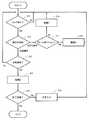
- FIG. 6is a flowchart showing the flow of character input processing in this embodiment. Step is abbreviated as S.
- S11After the input operation starts, in S11, it is determined whether or not the touch panel 11 is touched by the user. Such a determination is made based on information from the touch panel control unit 31. If it is not touched (No in S11), it waits until a touch is made again.
- the microcomputer 20determines whether the touch by the user is a tracing operation or a keystroke operation based on the result of the determination unit.
- the determination unitis the acceleration sensor 16, which senses acceleration in a direction perpendicular to the display surface of the display unit 12, and when it exceeds a certain threshold, it is a keystroke operation, and if it is less than that, it is a tracing operation It is determined by the microcomputer 20.
- S12If it is determined in S12 that the touch operation by the user is a tracing operation, the process proceeds to S17.
- S ⁇ b> 17position information on the touch panel 11 that the user is tracing is acquired from the touch panel control unit 31, and the microcomputer 20 determines whether the position is on the home position key 41.
- the processproceeds to S18.
- the vibration control unit 33controls the vibration unit 13 to give a tactile sense A to the user. The user can recognize that the finger is on the home position key 41 by feeling the sense of touch A from the touching finger.
- the processproceeds to S13.
- S ⁇ b> 13based on information from the touch panel control unit 31, the microcomputer 20 determines whether or not the user's keystroke position is within the operation area 45. If it is determined that the user has pressed a key other than the operation area 45, the process returns to S11 and waits until a touch is performed again.
- the processproceeds to S14.
- the vibration control unit 33controls the vibration unit 13 to give the user a sense of touch B. The user can recognize that the character input or the termination process has been performed by feeling the tactile sense B from the touching finger.
- FIG. 7is a schematic diagram illustrating an example of a vibration pattern according to the first embodiment.
- the vibration control unit 33applies a voltage having a waveform as shown in FIG. 7A to the vibration unit 13 and vibrates the touch panel 11, thereby giving the user a tactile sense A.
- the voltage for giving the haptic Ais a sine wave of 150 Hz, 70 Vrms, and two periods. The amplitude on the touch panel 11 at this time is about 5 ⁇ m.
- the vibration control unit 33applies a voltage as illustrated in FIG. 7B to the vibration unit 13 to vibrate the touch panel 11, thereby giving the user a sense of touch B.
- the voltage for giving the sense of touch Bis a sine wave, 300 Hz, 100 Vrms, 4 cycles.
- the frequency, voltage, and number of cyclesare merely examples, and other waveforms such as a rectangular wave and a sawtooth wave, an intermittent waveform, a waveform whose frequency and amplitude continuously change, and the like may be used.
- the vibration pattern for giving the tactile sense A and the vibration pattern for giving the tactile sense Bhave different vibration patterns, but the present invention is not limited to this.
- the vibration patterns of the sense of touch A and the sense of touch Bmay be the same.
- FIG. 8is an example of a screen display of the electronic device 10, and a QWERTY key is displayed on the display unit 12.
- the usertouches the QWERTY key displayed on the display unit 12 of the electronic device 10 to input and display characters in the input area 46.
- a home position key 41, a general key 42, an enter key 43, an end key 44, and an input area 46are displayed on the display unit 12.
- the operation area 45is an area including a home position key 41, a general key 42, an enter key 43, and an end key 44.
- the home position key 41is an “F” key and a “J” key, and two keys near the center of the QWERTY key.
- the microcomputer 20determines that the user has recognized the home position key 41, the microcomputer 20 enables the input mode. Thereby, the character input by the user's keystroke becomes valid and the character input is accepted. Thereafter, if the user does not touch the keyboard for a certain period, the microcomputer 20 determines that the user has not recognized the home position key 41 and invalidates the input mode. Thereby, the character input by the user's keystroke becomes invalid and the character input cannot be accepted.
- the general key 42is a key other than the home position key 41 among the character keys.
- the usercan input characters in the input area 46 by pressing the home position key 41 and the general key 42.
- the enter key 43is an enter key.
- the usercan input the character input in the input area 46 as information to the microcomputer 20 by pressing the enter key 43 after inputting the character. In that case, the input operation is terminated, and the electronic device 10 follows the instruction of the microcomputer 20.
- the end key 44is a key for ending the input operation.
- the usercan end the input operation without transmitting character information to the microcomputer 20 by pressing the end key 44 even during character input and after character input.
- FIG. 9is a flowchart showing the character input process in this embodiment. Step is abbreviated as S.
- S21After the input operation starts, in S21, it is determined whether or not the touch panel 11 is touched by the user. Such a determination is made based on information from the touch panel control unit 31. If not touched (No in S21), the process proceeds to S29. After the input mode invalidity determination process is performed in S29, the process waits until a touch is performed again in S21. The input mode invalidity determination process will be described later.
- the processproceeds to S22.
- the microcomputer 20determines whether the touch by the user is a tracing operation or a keystroke operation based on the result of the determination unit.
- the determination unitis an acceleration sensor 16 that senses acceleration in a direction perpendicular to the display surface of the display unit 12 and performs a keystroke operation when a certain threshold is exceeded, and a tracing operation when the threshold is lower than that. The microcomputer 20 determines that there is.
- S22If it is determined in S22 that the touch operation by the user is a tracing operation, the process proceeds to S30.
- S ⁇ b> 30information on the position on the touch panel 11 that the user is tracing is acquired from the touch panel control unit 31, and it is determined whether or not the position is on the home position key 41.
- the processproceeds to S31.
- the vibration control unit 33controls the vibration unit 13 to give the user a tactile sense A. The user can recognize that the finger is on the home position key 41 by feeling the sense of touch A from the touching finger.
- input mode validity determination processingis performed, and the process returns to S21. The input mode validity determination process will be described later.
- the processproceeds to S23.
- S ⁇ b> 23it is determined based on information from the touch panel control unit 31 whether or not the user's keystroke position is within the operation area 45. If it is determined that the user has pressed a key other than the operation area 45, the process returns to S11 and waits until a touch is performed again.
- S23If it is determined in S23 that the user has pressed the operation area 45, the process proceeds to S24.
- S ⁇ b> 24based on information from the touch panel control unit 31, it is determined whether the keystroke position by the user is the end key 44 or the enter key 43.
- the processproceeds to S25.
- the vibration control unit 33controls the vibration unit 13 to give the user a tactile sense C. The user can recognize that the termination processing or the character input confirmation has been performed by feeling the sense of touch C from the touching finger. Thereafter, if the user's keystroke position is the end key 44, the process is terminated. If the user's keystroke position is the enter key 43, the input information in the input area 46 is transmitted to the microcomputer 20 and the process is terminated. .
- the input modeis set to invalid and key input (character input) is invalid. Thereby, even if the general key 42 is touched before the finger reaches the home position, no character input is performed, and therefore it is possible to prevent a character input unintended by the user.
- FIG. 10is a flowchart showing the input mode validity determination process performed in S32.
- S42it is determined whether or not all home position keys 41 are touched by the user. Thereby, the microcomputer 20 determines that the user's forefinger has recognized the QWERY key F and J. If it is determined in S42 that the user has touched all the home position keys 41 (Yes in S42), the process proceeds to S43. If it is determined in S42 that all the home position keys 41 have not been touched (No in S42), the input mode validity determination process is terminated.
- S43it is determined whether the time during which the user's touch position stored in the RAM 39 remains on the home position key 41 is longer than a certain time. More than a certain time is about 0.1 s to 2.0 s.
- the microcomputer 20determines that the user has recognized the home position key 41.
- step S43If it is determined in S43 that the user has touched the home position key 41 for a certain period of time (Yes in S43), the input mode is validated in S44 and the input mode is valid in the RAM 39.
- step S45the keyboard color is changed, and it is presented visually that the input mode is valid. Then, the input mode validity determination process is terminated.
- the input modemay be validated when the user touches the home position key 41 for a predetermined time or more and then releases the finger from the home position key 41. Thereby, it is possible to prevent unintentional input of the key touched at the timing when the input mode switches from invalid to valid.
- FIG. 11is a flowchart showing the input mode invalidity determination process in S29 (FIG. 9).
- S51it is determined whether the current input mode is valid / invalid. Information on whether the input mode is valid or invalid is stored in the RAM 39. If the current input mode is invalid, the input mode invalidity determination process is terminated.
- S52it is determined whether the time during which the user does not touch the operation area 45 is a certain time or more. The time when the user is not touching the operation area 45 is stored in the RAM 39. More than a certain time is generally 1 s to 10 s. If the user has not touched the operation area 45 for a certain time or longer, the microcomputer 20 determines that the user has not recognized the position of the home position key 41. In order to determine that the user has not touched the operation area 45 for a predetermined time or longer, it is desirable to store the time during which the user has not touched the operation area 45 in the RAM 39 in S21.
- input mode changesmay be presented by hearing or touch.
- Embodiment 3Next, an electronic apparatus according to Embodiment 3 will be described.
- the electronic device 10 according to the third embodimentgenerates vibration even when the user touches a button other than the home position (an example of a non-reference area) in order to search for a home position (an example of a reference area).
- a button other than the home positionan example of a non-reference area
- a home positionan example of a reference area
- FIG. 13is a flowchart illustrating processing of the electronic device 10 according to the third embodiment.
- S17when the user has not touched the home position (No in S17), the process proceeds to S19.
- the vibration control unit 33controls the vibration unit 13 to give the user a sense of touch C.
- S ⁇ b> 17when the user touches the home position (Yes in S ⁇ b> 17), the tactile sense A is given as in the first embodiment.
- the userWhen the user performs a tracing operation to search for a home position, the user can obtain different tactile sensations depending on whether the user touches a position other than the home position or the home position. Thereby, the user can know whether he / she touched the home position. In addition, since the tactile sense C is given to the user when the user touches a position other than the home position, the user can recognize that he / she is looking for the home position.
- the vibration pattern of tactile Cis set as appropriate. When different vibration patterns are used, the period and amplitude of vibration may be changed. Thereby, the user can feel the vibration strongly or weakly.
- vibration patterns of tactile sense A, tactile sense B, and tactile sense Ccan be as follows.
- the usercan recognize whether the user is searching for a home position or performing a character input operation.
- ⁇ Pattern 4A ⁇ B ⁇ C>
- the vibration pattern of the tactile sense A, the vibration pattern of the tactile sense B, and the vibration pattern of the tactile sense Cmay all be different from each other. As a result, the user can recognize what operation he / she is performing.
- the electronic device 10includes the display unit 12, the touch panel 11, the vibration unit 13, the vibration control unit 33, and the acceleration sensor 16.
- the display unit 12displays an operation area 45 having a home position key 41 that is an example of a reference area and a general key 42 that is an example of a non-reference area.
- the touch panel 11is disposed so as to cover at least the operation area 45.
- the vibration unit 13is an example of a notification unit, and notifies the user of the operation status of the user.
- the vibration control unit 33is an example of a control unit and controls the vibration unit 13.
- the acceleration sensor 16is an example of a determination unit, and determines a first operation in which a user searches for a reference area on the touch panel 11 and a second operation that is a key input operation to the operation area 45.
- the vibration control unit 33controls the vibration unit 13 based on the result detected by the acceleration sensor 16.
- the user's operationis determined by the acceleration sensor 16, and vibration corresponding to the operation is given to the user. Therefore, the user can know what operation he / she performed or whether his / her operation was recognized by the electronic device 10. As a result, the user can easily perform input to the electronic device 10.
- the electronic device 10includes a display unit 12, a touch panel 11, a touch panel control unit 31, and a microcomputer 20 that is an example of a control unit.
- the display unit 12displays an operation area 45 having a home position key 41 that is an example of a reference area and a general key 42 that is an example of a non-reference area.
- the touch panel 11is disposed so as to cover at least the operation area 45.
- the touch panel control unit 31can determine whether the user touches a home position key 41 that is an example of a reference area or a general key 42 that is an example of a non-reference area.
- the microcomputer 20validates the input to the touch panel 11 by the user.
- the electronic device 10By providing the electronic device 10 with such a configuration, it is possible to prevent a key input to the electronic device 10 by mistake when the user performs an operation of searching for the home position 41. Therefore, the user can easily perform input to the electronic device 10.
- the operation of the electronic device 10 described abovemay be realized by hardware or software.
- a program for executing such a control operationis stored in the built-in memory of the microcomputer 20 or the ROM 38, for example.
- such a computer programmay be installed in the electric device 10 from a recording medium (such as an optical disk or a semiconductor memory) on which the computer program is recorded, or may be downloaded via an electric communication line such as the Internet.
- Embodiments 1 to 3have been illustrated as embodiments of the present invention, the present invention is not limited to these. For example, the following embodiments are also included in the present invention.
- the notification unitis not limited to the vibration unit 13.
- the notification unitis the speaker 17 and may be configured to notify the user of information by voice.
- the notification unitmay be configured to notify the user of information by light. Such a configuration can be realized, for example, when the display control unit 32 controls the display unit 12.
- the notification unitmay be configured to notify the user of information by heat or electric shock.
- FIG. 12is an example of a screen display of the electronic device 10 and shows operation keys such as a car navigation system and a car radio.
- the usercan operate the car navigation system and the car radio by touching the operation keys displayed on the display unit 12 of the electronic device 10.
- a home position key 41, a general key 42, an enter key 43, and an end key 44are displayed on the display unit 12.
- the operation areaindicates an area including a home position key 41, a general key 42, an enter key 43, and an end key 44.
- the usersearches for the home position key 41 without looking at the touch panel, estimates the position of various operation keys based on the relative position from the home position key 41, and selects a general key by key-pressing operation. Play, stop, volume up, down, channel change, etc.
- the determination unitis not limited to the acceleration sensor 16.
- the vibration unit 13is a vibrator including the piezoelectric element 21
- the vibration of the piezoelectric element 21can be converted into a voltage by the piezoelectric effect and the voltage can be supplied to the vibration control unit 33.
- the user's keystroke operationis converted into a voltage by the vibration unit 13 and output to the vibration control unit 33.
- the microcomputer 20can recognize that the user has performed a key pressing operation.
- the touch panel control unit 31can also determine whether the user operation is a keystroke operation or a tracing operation. For example, when the touch panel 11 is a resistive film type, the contact area of the upper and lower layers can be recognized by the resistance value, and therefore it is possible to determine whether the operation is a tracing operation or a keystroke operation from the rate of change of the contact area with time. .
- the touch panel 11is a capacitive type
- the contact area of the user's finger to the touch panel 11 and whether the user's finger has approached the touch panel 11can be recognized by a change in the capacitance.
- the change in capacitanceit can be determined whether the operation is a tracing operation or a key pressing operation. That is, the capacitance change is small in the case of the tracing operation, and the capacitance change is large in the case of the keystroke operation.
- Embodiments 1 to 3have been described using a tablet-type information terminal device as an example of an electronic device, but the electronic device of the present invention is not limited to this.
- the present inventionis applied to an electronic device including a touch panel, such as a mobile phone, a PDA, a game machine, a car navigation system, and an ATM.
- the touch panel that covers the entire display surface of the display unit 12is exemplified, but the present invention is not limited to this.
- the touch panel functionmay be provided only at the center of the display surface, and the peripheral part may not be covered by the portion having the touch panel function. In short, it is sufficient if it covers at least the input operation area of the display unit.
- the touch panel 11 and the display unit 12are separate bodies, but the present invention is not limited to this.
- the touch panel 11may be bonded to the display unit 12.
- the display unit 12may have a function of detecting the touch position. In short, it is only necessary that the touch position can be detected.
- the touch panel 11is vibrated, but the present invention is not limited to this.
- a cover glassis arranged outside the touch panel 11, it may be vibrated.
- what is necessaryis just to be able to vibrate the member which a user contacts.
- the present inventionis useful for an electronic device that can be touched by a user, for example.
Landscapes
- Engineering & Computer Science (AREA)
- General Engineering & Computer Science (AREA)
- Theoretical Computer Science (AREA)
- Human Computer Interaction (AREA)
- Physics & Mathematics (AREA)
- General Physics & Mathematics (AREA)
- Position Input By Displaying (AREA)
- User Interface Of Digital Computer (AREA)
Abstract
Description
Translated fromJapanese本発明は、ユーザによるタッチ操作が可能な電子機器に関する。The present invention relates to an electronic device that can be touched by a user.
表示画面上にタッチパネルが配置された電子機器において、ユーザへの操作性向上のために、タッチパネルを振動させることにより、ユーザに触覚を与える技術が知られている。タッチパネルが配置された電子機器においては、画面上に表示されたキーボードをタッチすることによって文字入力を行ういわゆるソフトキーボードが多く用いられる。しかし、ソフトキーボードは、実際のキーボードとは違い凹凸がないので、キーボード上の基準領域(ホームポジション、QWERTYキーボードにおけるF、Jの位置、10キーにおける5の位置)の認識が困難であるという課題があった。この課題を解決するために、特許文献1では、ホームポジションのキーに触れたときとホームポジション以外のキーに触れたときでは別の振動による触覚を提示してユーザにホームポジションの位置を認識させる技術が開示されている。In an electronic device in which a touch panel is arranged on a display screen, a technique for giving a tactile sensation to a user by vibrating the touch panel is known to improve operability for the user. In an electronic device in which a touch panel is arranged, a so-called soft keyboard that performs character input by touching a keyboard displayed on a screen is often used. However, since the soft keyboard is not uneven unlike an actual keyboard, it is difficult to recognize the reference area on the keyboard (home position, F, J position on the QWERTY keyboard, 5 position on the 10 key). was there. In order to solve this problem, in
特許文献1では、ホームポジションのキーに触れたときと、ホームポジション以外のキーに触れたときでは、違う振動による触覚を提示する。しかし、ソフトキーボードの場合は接触により文字入力を行うので、文字入力を意図していないキーに触れた場合でも、そのキーに割り当てられた文字が入力されてしまうことになる。例えば、キーボードのブラインドタッチにおいて、ホームポジションを探すときにキーボードの表面を指で軽くなぞる動作が行われるが、そのようななぞる動作だけでも誤って文字入力がなされてしまうことになる。特許文献1は、ホームポジションを探すときに指でなぞる動作と、キーボードを打鍵し入力する動作とを判別する点については何も開示していない。その為、特許文献1の構成では、ホームポジションを探す動作を行っている間に入力動作がなされてしまい、所望の入力以外の入力が行われてしまうおそれがある。In
本発明は、上記課題を鑑みてなされたものであり、ユーザが意図する入力操作を容易に行うことができる電子機器を提供する。The present invention has been made in view of the above problems, and provides an electronic device that can easily perform an input operation intended by a user.
本発明の電子機器は、基準領域と非基準領域とを有する操作領域を表示する表示部と、前記表示部の表示面側に設けられたタッチパネルと、ユーザに対して、前記ユーザの操作状況を知らせる報知部と、前記報知部の動作を制御する制御部と、前記タッチパネル上で前記ユーザが前記基準領域を探す第1操作と、前記操作領域へのキー入力操作である第2操作とを判別する判別部とを備え、前記制御部は、前記判別部の判別結果に基づいて前記報知部の動作を制御することを特徴とする。An electronic device according to the present invention provides a display unit that displays an operation region having a reference region and a non-reference region, a touch panel provided on a display surface side of the display unit, and a user operation status to the user. A notification unit for notifying, a control unit for controlling the operation of the notification unit, a first operation for the user to search for the reference region on the touch panel, and a second operation that is a key input operation to the operation region are determined. And a control unit that controls an operation of the notification unit based on a determination result of the determination unit.
ある実施形態によれば、前記報知部は、前記ユーザに対して触覚を提供する触覚提供部である。According to an embodiment, the notification unit is a tactile provision unit that provides a tactile sense to the user.
ある実施形態によれば、前記触覚提供部は、前記タッチパネルを振動させる振動部である。According to an embodiment, the tactile sensation providing unit is a vibrating unit that vibrates the touch panel.
ある実施形態によれば、前記第1操作は、前記タッチパネル上での前記ユーザの接触位置が連続的に変化する操作であり、前記第2操作は、前記タッチパネル上での打鍵操作である。According to an embodiment, the first operation is an operation in which the contact position of the user on the touch panel changes continuously, and the second operation is a keystroke operation on the touch panel.
ある実施形態によれば、前記制御部は、前記第1操作において前記ユーザが前記非基準領域を接触しているときと前記基準領域を接触しているときとで前記振動部の動作を異ならせる。According to an embodiment, the control unit varies the operation of the vibration unit between when the user is in contact with the non-reference area and when the user is in contact with the reference area in the first operation. .
ある実施形態によれば、前記制御部は、前記第1操作の間は前記操作領域へのキー入力を無効に設定する。According to an embodiment, the control unit disables key input to the operation area during the first operation.
ある実施形態によれば、前記制御部は、前記ユーザが前記基準領域を所定時間以上連続して接触した後、前記操作領域へのキー入力を無効から有効に設定する。According to an embodiment, the control unit sets the key input to the operation area from invalid to valid after the user touches the reference area continuously for a predetermined time or more.
ある実施形態によれば、前記制御部は、前記ユーザが前記基準領域を前記所定時間以上連続して接触した後、前記基準領域への接触が無くなった場合に前記操作領域へのキー入力を無効から有効に設定する。According to an embodiment, the control unit invalidates a key input to the operation area when the user stops touching the reference area after the user continuously contacts the reference area for the predetermined time or longer. Set to valid from.
ある実施形態によれば、前記制御部は、前記ユーザが前記操作領域を所定時間以上接触しなかった場合、前記操作領域へのキー入力を有効から無効に設定する。According to an embodiment, the control unit sets the key input to the operation area from valid to invalid when the user does not touch the operation area for a predetermined time or more.
ある実施形態によれば、前記制御部は、前記第1操作のときと前記第2操作のときとで前記振動部の振動パターンを異ならせる。According to an embodiment, the control unit varies a vibration pattern of the vibration unit between the first operation and the second operation.
ある実施形態によれば、前記制御部は、前記第1操作において前記ユーザが前記基準領域に接触したときに第1の振動パターンで前記振動部が振動するように制御し、前記制御部は、前記第2操作において前記ユーザが前記操作領域に接触したときに、前記第1の振動パターンとは異なる第2の振動パターンで前記振動部が振動するように制御する。According to an embodiment, the control unit controls the vibration unit to vibrate in a first vibration pattern when the user contacts the reference region in the first operation, and the control unit includes: When the user touches the operation area in the second operation, the vibration unit is controlled to vibrate with a second vibration pattern different from the first vibration pattern.
本発明のプログラムは、タッチパネル上でのユーザの操作状況を前記ユーザに知らせる動作を電子機器に実行させるプログラムであって、前記プログラムは、前記タッチパネル上で前記ユーザが基準領域を探す第1操作と、操作領域へのキー入力操作である第2操作とを判別するステップと、前記判別結果に基づいて前記ユーザに知らせる動作を制御するステップとを前記電子機器に実行させることを特徴とする。The program according to the present invention is a program for causing an electronic device to execute an operation for notifying the user of an operation state of a user on a touch panel, and the program includes a first operation for the user to search for a reference area on the touch panel. The electronic device is caused to execute a step of determining a second operation, which is a key input operation to the operation area, and a step of controlling an operation to notify the user based on the determination result.
本発明によれば、タッチパネル上でユーザが基準領域を探す操作と操作領域へのキー入力操作とを判別する。これにより、入力を意図していないキーに触れた場合に誤ってキー入力されてしまうことを防止することができる。また、その判別結果に基づいて報知部の動作を制御することにより、ユーザは現在の操作状況を容易に認識することができる。According to the present invention, the operation for searching the reference area by the user on the touch panel and the key input operation to the operation area are discriminated. As a result, it is possible to prevent an erroneous key input when a key that is not intended for input is touched. Further, by controlling the operation of the notification unit based on the determination result, the user can easily recognize the current operation status.
(実施形態1)
<構成の説明>
図1、図2、図3を用いて、本実施形態の電子機器10の全体構成を説明する。(Embodiment 1)
<Description of configuration>
The overall configuration of the
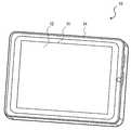
図1は、電子機器10の外観を示す斜視図である。図2は、電子機器10の構成を示すブロック図である。FIG. 1 is a perspective view showing an external appearance of the
図1および図2に示すように、電子機器10は主として、表示部12と、それを覆うように配置されたタッチパネル11と、タッチパネル11を振動させる振動部13と、振動部13の振動を制御する振動制御部33と、ユーザによるタッチ操作により生じる電子機器10の加速度を測定する加速度センサ16とを備える。As shown in FIGS. 1 and 2, the
ユーザは、表示部12に表示された内容を指やペンなどによりタッチすることで、電子機器10を操作する。筐体14の中には、回路基板19が配置されており、回路基板19には、マイクロコンピュータ20等の各種電子部品が取り付けられている。The user operates the
表示部12は、文字や数字、図形、キーボード等を表示する。表示部12には、ユーザが操作可能な領域である操作領域45が含まれている。操作領域45には、例えば、キーボードのような、ユーザからの入力を受け付けるためのものが表示される。ユーザは、表示部12に表示されたキーボードの任意の位置をタッチ操作することにより、文字入力等を行うことができる。操作領域45には、さらに基準領域と非基準領域とが含まれる。これらの詳細については後述する。表示部12として、液晶、有機EL、電子ペーパー、プラズマなどの公知の技術を用いた表示装置を用いることができる。
表示制御部32は、マイクロコンピュータ20によって生成される制御信号に基づいて、表示部12への表示内容を制御する。The
タッチパネル11は、表示部12の表示面側に設けられ、少なくとも操作領域45を覆うように表示部12上に配置されている。ユーザは、タッチパネル11上を指やペンなどでタッチ操作することで電子機器10を操作することができる。タッチパネル11は、ユーザのタッチ位置を検知することができる。ユーザのタッチ位置の情報は、タッチパネル制御部31を介してマイクロコンピュータ20に送られる。マイクロコンピュータ20は、ユーザのタッチ位置の情報を用いて後述する各種処理を行う。The
タッチパネル11として、例えば、静電式、抵抗膜式、光学式、超音波方電磁式などのタッチパネルを用いることができる。As the
振動部13は、タッチパネル11を振動させる。振動部13は、ユーザに対して触覚を提供する触覚提供部の一例である。振動制御部33は、振動部13の振動パターンを制御する。振動部13の構成や、振動パターンの詳細については後述する。The
カメラ15は、電子機器10に搭載されており、カメラ制御部35により制御される。The
外部通信部36は、例えばインターネットや、パーソナルコンピュータ等への通信を可能とする通信手段である。The
加速度センサ16は、ユーザによるタッチ操作により生じる電子機器10の加速度を測定する。具体的に説明すると、ユーザがタッチパネル表面を指でなぞるように操作したときは、ユーザの操作により電子機器10に生じる衝撃は小さいため、加速度センサ16により測定される加速度も小さい。一方、ユーザが操作領域45に表示された任意の文字をタッチすることで文字を入力しようとした場合、ユーザの指はタッチパネル11を軽く叩くような動作になる。このような動作のときは、ユーザの操作により電子機器10に生じる衝撃は大きいため、加速度センサ16により測定される加速度も大きい。加速度センサ16は、このようなユーザの操作により発生する加速度を測定することができる。加速度センサ16で測定された加速度は、マイクロコンピュータ20に送られる。マイクロコンピュータ20は、この加速度の大きさに基づいて、振動制御部33に振動パターンに関する制御信号を送る。振動制御部33は、マイクロコンピュータ20からの制御信号に基づいて、加速度の大きさに応じて異なる振動パターンで振動するように、振動部13を振動させる。The
加速度センサ16は、ユーザがタッチパネル11上で基準領域を探す第1操作と、操作領域45へのキー入力操作である第2操作とを判別する判別部の一例である。The
また、電子機器10は、音声を発生するスピーカ17や、各種電子機器に対して入出力可能な各種入出力部37を備える。In addition, the
図3は、電子機器10の断面図である。本実施形態の電子機器10では、表示部12、振動部13、回路基板19が、筐体14の中に格納されている。回路基板19には、マイクロコンピュータ20、RAM38、ROM39、各種制御部、電源などが配置されている。FIG. 3 is a cross-sectional view of the
振動部13は、タッチパネルに実装されており、タッチパネル11を振動させることにより、ユーザに触覚を与えることができる。タッチパネル11は筐体14とスペーサ18を介して配置されており、スペーサ18によって、タッチパネル11の振動が、筐体14に伝わりにくいようになっている。スペーサ18は、例えば、シリコンゴムやウレタンゴム等の緩衝部材である。The
表示部12は、筐体14の中に配置されており、タッチパネル11は、表示部12を覆うように配置されている。タッチパネル11、振動部13、表示部12は、それぞれ電気的に回路基板に接続されている。The
図4を用いて振動部13の構成を説明する。図4は、本実施形態の振動部13の斜視図である。振動部13は、圧電素子21とシム板22とベース23とを備える。シム板22の両側には、圧電素子21が接着されている。シム板22の両端がベース23と接続されており、いわゆる両持ち構成になっている。ベース23は、タッチパネル11と接続されている。The configuration of the
圧電素子21は、チタン酸ジルコン酸鉛等の圧電セラミックやニオブ酸リチウム等の圧電単結晶である。圧電素子21は、振動制御部33からの電圧により、伸縮する。シム板22の両側に貼り付けられた圧電素子21の片方が伸びて、他方が縮むように制御することで、シム板にたわみ振動を発生させることができる。The
シム板22は、リン青銅等のバネ部材である。シム板22の振動はベース基板23を通じて、タッチパネル11を振動させ、タッチパネルを操作しているユーザはタッチパネルの振動を感知することができる。The
ベース23は、アルミや真鍮等の金属や、PETやPP等のプラスチックである。The
振動の周波数、振幅、期間は振動制御部33によって制御される。振動の周波数としては、100~400Hz程度の周波数が望ましい。The vibration frequency, amplitude, and period are controlled by the
なお、本実施形態では、圧電素子21をシム板22に貼り付けているが、圧電素子21を直接タッチパネル11に貼り付けてもよい。また、スパッタリング等の方法によりタッチパネル11に薄膜の圧電部材を形成して振動部13として用いてもよい。In this embodiment, the
また、タッチパネル11の上にカバー部材等がある場合は、圧電素子21をカバー部材に貼り付けてもよい。また、圧電素子21の替わりに振動モータを用いてもよい。Further, when there is a cover member or the like on the
<動作の説明>
図5、図6、図7を用いて、文字入力動作について説明する。<Description of operation>
The character input operation will be described with reference to FIGS.
図5は、電子機器10の画面表示の一例であり、テンキーを表示している。ユーザは、電子機器10の表示部12に表示されたテンキーにタッチすることで、入力領域46に数字が入力されて表示される。表示部12には、ホームポジションキー41と、一般キー42と、エンターキー43と、終了キー44と、入力領域46が表示されている。操作領域(有効領域)45は、ホームポジションキー41と、一般キー42と、エンターキー43と、終了キー44を含む領域を示す。FIG. 5 is an example of a screen display of the
ホームポジションキー41は、テンキーの場合は“5”のキーであり、テンキーの中央部のキーである。ユーザは、最初に指をホームポジションキー41の位置に配置した後に、キーボードの打鍵による数字の入力操作を行うことで、キーボードの数字を見なくても、数字入力を行い易くなる。ホームポジションキー41は基準領域の一例であり、一般キー42は非基準領域の一例である。ユーザがホームポジションキー41を指で探す場合、ユーザはタッチパネル11上を指でなぞるように操作する。具体的には、タッチパネル上でのユーザのタッチ位置が連続的に変化する操作である。以下、このような操作を“なぞり操作”と称する。The home position key 41 is a “5” key in the case of a numeric keypad, and is a key at the center of the numeric keypad. A user first places a finger at the position of the home position key 41 and then performs a numeric input operation by keystroke on the keyboard, thereby making it easier to input numbers without looking at the numbers on the keyboard. The home position key 41 is an example of a reference area, and the
一般キー42は、数字キーのうちのホームポジションキー41以外のキーである。ユーザは、ホームポジションキー41および一般キー42を打鍵することで、入力領域46に数字を入力することができる。General key 42 is a key other than the home position key 41 among the numeric keys. The user can input numbers in the
エンターキー43は、ユーザによる入力内容を確定するためのキーである。数字入力後、ユーザがエンターキー43を打鍵することで、入力領域46に入力された数字が、マイクロコンピュータ20に情報として送信される。その場合には、入力動作は終了し、電子機器10はマイクロコンピュータ20の命令に従う。The
終了キー44は、入力操作の終了キーである。ユーザは、数字入力中および数字入力後であっても、終了キー44を打鍵することで、マイクロコンピュータ20に、数字情報を送信することなく、入力動作を終了することができる。The
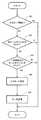
図6は、本実施形態における文字入力の処理の流れを示すフローチャートである。ステップはSと略する。FIG. 6 is a flowchart showing the flow of character input processing in this embodiment. Step is abbreviated as S.
入力動作がスタートした後、S11において、ユーザによりタッチパネル11がタッチされたかどうかについて判断される。このような判断は、タッチパネル制御部31からの情報に基づいて行われる。タッチされていない場合(S11でNo)には、再度タッチが行われるまで待機する。After the input operation starts, in S11, it is determined whether or not the
S11でユーザによるタッチが有ると判断されると、ユーザによるタッチが、なぞり操作なのか、打鍵操作なのかが判別部の結果に基づいてマイクロコンピュータ20により判断される。本実施形態では、判別部は加速度センサ16であり、表示部12の表示面に垂直な方向の加速度をセンシングし、ある閾値を超えた場合は打鍵操作、それ以下の場合はなぞり操作であるとマイクロコンピュータ20により判断される。If it is determined in S11 that there is a touch by the user, the
S12で、ユーザによるタッチ操作がなぞり操作であると判断された場合には、S17に進む。S17では、タッチパネル制御部31から、ユーザがなぞっているタッチパネル11上の位置情報が取得され、その位置がホームポジションキー41上にあるか否かがマイクロコンピュータ20により判断される。If it is determined in S12 that the touch operation by the user is a tracing operation, the process proceeds to S17. In S <b> 17, position information on the
ユーザのなぞり位置がホームポジションキー41上にあると判断された場合(S17でYes)は、S18に進む。S18では、振動制御部33が振動部13を制御することで、ユーザに触覚Aを与えられる。ユーザは、タッチしている指から触覚Aを感じることで、指がホームポジションキー41上にあることを認識できる。If it is determined that the user's tracing position is on the home position key 41 (Yes in S17), the process proceeds to S18. In S <b> 18, the
ユーザのなぞり位置がホームポジションキー41上にないと判断された場合(S17でNo)には、再度S11へ戻り、タッチ操作の判断を待つ。If it is determined that the user's tracing position is not on the home position key 41 (No in S17), the process returns to S11 again and waits for a touch operation determination.
一方、S12において、判別部により、ユーザのタッチが打鍵操作であると判断された場合には、S13に進む。S13では、タッチパネル制御部31からの情報に基づいて、ユーザの打鍵位置が操作領域45内にあるか否かがマイクロコンピュータ20により判断される。ユーザが操作領域45以外を打鍵したと判断された場合には、S11に戻り再度タッチが行われるまで待機する。On the other hand, when the determination unit determines in S12 that the user's touch is a keystroke operation, the process proceeds to S13. In S <b> 13, based on information from the touch
S13で、ユーザが操作領域45を打鍵したと判断された場合には、S14に進む。S14では振動制御部33が振動部13を制御することで、ユーザに触覚Bが与えられる。ユーザは、タッチしている指から触覚Bを感じることで、文字入力や終了処理を行ったことを認識できる。If it is determined in S13 that the user has pressed the
その後S15にて、タッチパネル制御部31からの情報に基づいて、入力操作が終了したか否かが判定される。具体的には、ユーザによる打鍵位置が、終了キー44またはエンターキー43であるかが判断される。ユーザによる打鍵位置が終了キー44の場合は入力操作を終了する。一方、ユーザによる打鍵位置がエンターキー43である場合には、入力領域46に入力された情報をマイクロコンピュータ20に送信後、入力操作を終了する。Thereafter, in S15, based on the information from the touch
打鍵位置が、終了キー44およびエンターキー43でない場合(S15でNo)には、S16に進む。S16では、打鍵された位置に表示してある数字を入力領域46に表示する文字入力動作が行われ、S11に戻り、次のタッチ操作まで待機する。If the keystroke position is not the
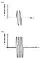
図7は、実施形態1の振動パターンの一例を示す概略図である。FIG. 7 is a schematic diagram illustrating an example of a vibration pattern according to the first embodiment.
マイクロコンピュータ20の命令により、振動制御部33が、振動部13へ図7(a)に示すような波形の電圧を印加し、タッチパネル11を振動させることで、ユーザに触覚Aを与える。一例として、触覚Aを与えるための電圧は正弦波で、150Hz、70Vrms、2周期である。このときのタッチパネル11上の振幅は、約5μm程度である。また、振動制御部33が、振動部13へ図7(b)に示すような電圧を印加し、タッチパネル11を振動させることで、ユーザに触覚Bを与える。一例として、触覚Bを与えるための電圧は正弦波で、300Hz、100Vrms、4周期である。周波数、電圧、周期数に関しては一例であり、矩形波やのこぎり波などの別の波形、間欠的な波形、連続的に周波数や振幅が変化する波形などでもよい。In response to a command from the
なお、本実施形態では、触覚Aを与えるための振動パターンと触覚Bを与えるための振動パターンとは異なる振動パターンとしたが、これに限らない。触覚Aと触覚Bの振動パターンは同じでもよい。In the present embodiment, the vibration pattern for giving the tactile sense A and the vibration pattern for giving the tactile sense B have different vibration patterns, but the present invention is not limited to this. The vibration patterns of the sense of touch A and the sense of touch B may be the same.
(実施形態2)
以下、実施形態2に係る電子機器について説明する。なお、実施形態2に係る電子機器は、上述の実施形態1に係る電子機器と同様の構成を有しているため、再度の説明を省略し、ここでは実施形態1と異なる点について説明する。(Embodiment 2)
Hereinafter, an electronic apparatus according to the second embodiment will be described. Note that the electronic device according to the second embodiment has the same configuration as the electronic device according to the above-described first embodiment, and thus description thereof will be omitted. Here, differences from the first embodiment will be described.
<動作の説明>
図8、図9、図10、図11を用いて、実施形態2に係る電子機器10の文字入力動作について説明する。<Description of operation>
A character input operation of the
図8は、電子機器10の画面表示の一例であり、表示部12にはQWERTYキーが表示されている。ユーザは、電子機器10の表示部12に表示されたQWERTYキーにタッチすることで、入力領域46に文字を入力して表示させる。表示部12には、ホームポジションキー41と、一般キー42と、エンターキー43と、終了キー44と、入力領域46が表示されている。操作領域45は、ホームポジションキー41と、一般キー42と、エンターキー43と、終了キー44を含む領域である。FIG. 8 is an example of a screen display of the
ホームポジションキー41は、QWERTYキーの場合、“F”のキーと“J”のキーでありQWERTYキーの中央付近の2つのキーである。ユーザは、最初に両手の人差し指をホームポジションキーの位置に配置した後に、キーボードの打鍵による文字の入力操作を行うことで、キーボードの文字を見なくても、文字入力をすることが容易となる。マイクロコンピュータ20は、ユーザがホームポジションキー41を認識したと判断した場合には、入力モードを有効にする。これにより、ユーザの打鍵による文字入力が有効となり、文字入力が受け付けられる。その後、ユーザが一定期間キーボードをタッチしなかった場合には、マイクロコンピュータ20はユーザがホームポジションキー41を認識していないと判断し、入力モードを無効にする。これにより、ユーザの打鍵による文字入力が無効となり、文字入力が受け付けられなくなる。In the case of the QWERTY key, the home position key 41 is an “F” key and a “J” key, and two keys near the center of the QWERTY key. By first placing the index fingers of both hands at the position of the home position key and then performing a character input operation by pressing the keyboard, the user can easily input characters without looking at the characters on the keyboard. . When the
一般キー42は、文字キーのうちのホームポジションキー41以外のキーである。ユーザは、ホームポジションキー41および一般キー42を打鍵することで、入力領域46に文字を入力することができる。The
エンターキー43は、決定キーである。ユーザは文字入力後、エンターキー43を打鍵することで、入力領域46に入力された文字を、マイクロコンピュータ20に情報として送信することができる。その場合には、入力動作は終了し、電子機器10はマイクロコンピュータ20の命令に従う。The
終了キー44は、入力操作の終了を行うキーである。ユーザは、文字入力中および文字入力後であっても、終了キー44を打鍵することで、マイクロコンピュータ20に文字情報を送信することなく、入力動作を終了することができる。The
図9は、本実施形態における文字入力処理を示すフローチャートである。ステップはSと略する。FIG. 9 is a flowchart showing the character input process in this embodiment. Step is abbreviated as S.
入力動作がスタートした後、S21において、ユーザによりタッチパネル11がタッチされたかどうかについて判断される。このような判断は、タッチパネル制御部31からの情報に基づいて行われる。タッチされていない場合(S21でNo)には、S29に進む。S29で、入力モード無効判断処理がなされた後、S21で再度タッチが行われるまで待機する。入力モード無効判断処理については、後述する。After the input operation starts, in S21, it is determined whether or not the
S21でユーザによるタッチが有ると判断されると、S22に進む。S22では、ユーザによるタッチが、なぞり操作なのか打鍵操作なのかが判別部の結果に基づいてマイクロコンピュータ20により判断される。本実施形態では、判別部は、加速度センサ16であり、表示部12の表示面に垂直な方向の加速度をセンシングし、ある閾値を超えた場合は打鍵操作と、それ以下の場合はなぞり操作であるとマイクロコンピュータ20により判断する。If it is determined in S21 that there is a touch by the user, the process proceeds to S22. In S22, the
S22で、ユーザによるタッチ操作がなぞり操作であると判断された場合には、S30に進む。S30では、タッチパネル制御部31から、ユーザがなぞっているタッチパネル11上の位置の情報が取得され、その位置がホームポジションキー41上にあるか否かが判断される。If it is determined in S22 that the touch operation by the user is a tracing operation, the process proceeds to S30. In S <b> 30, information on the position on the
ユーザのなぞり位置がホームポジションキー41上にあると判断された場合(S30でYes)は、S31に進む。S31では、振動制御部33が振動部13を制御することで、ユーザに触覚Aが与えられる。ユーザは、タッチしている指から触覚Aを感じることで、指がホームポジションキー41上にあることを認識できる。その後S32にて、入力モード有効判断処理を行い、S21に戻る。入力モード有効判断処理については、後述する。If it is determined that the user's tracing position is on the home position key 41 (Yes in S30), the process proceeds to S31. In S <b> 31, the
ユーザのなぞり位置がホームポジションキー41上にないと判断された場合(S30でNo)には、再度S21へ戻り、タッチ操作の判断を待つ。If it is determined that the user's tracing position is not on the home position key 41 (No in S30), the process returns to S21 again and waits for a touch operation determination.
一方、S22で判別部により、ユーザのタッチが打鍵操作であると判断された場合には、S23に進む。S23では、タッチパネル制御部31からの情報に基づいて、ユーザの打鍵位置が操作領域45内にあるか否かが判断される。ユーザが操作領域45以外を打鍵したと判断された場合には、S11に戻り再度タッチが行われるまで待機する。On the other hand, if the determination unit determines in S22 that the user's touch is a keystroke operation, the process proceeds to S23. In S <b> 23, it is determined based on information from the touch
S23で、ユーザが操作領域45を打鍵したと判断された場合には、S24に進む。S24では、タッチパネル制御部31からの情報に基づいて、ユーザによる打鍵位置が、終了キー44またはエンターキー43であるかが判断される。If it is determined in S23 that the user has pressed the
打鍵位置が、終了キー44またはエンターキー43であると判断された場合には、S25に進む。S25では、振動制御部33が振動部13を制御することで、ユーザに触覚Cが与えられる。ユーザは、タッチしている指から触覚Cを感じることで、終了処理または文字入力確定を行ったことを認識できる。その後、ユーザによる打鍵位置が終了キー44の場合は処理を終了し、ユーザによる打鍵位置がエンターキー43である場合には、入力領域46の入力情報をマイクロコンピュータ20に送信後、処理を終了する。If it is determined that the keystroke position is the
S24にて、ユーザによる打鍵位置が、終了キー33およびエンターキー43でない場合には、S26にて、入力モードが有効であるかが判断される。入力モードが有効であると判断された場合(S26でYes)には、S27に進む。S27では、振動制御部33が振動部13を制御することで、ユーザに触覚Bが与えられる。ユーザは、タッチしている指から触覚Bを感じることで、文字入力を行ったことが認識できる。そして、S28にて、打鍵された位置に表示してある文字を入力領域46に表示し、S21に戻り次のタッチまで待機する。If it is determined in S24 that the keystroke position by the user is not the
S26にて入力モードが有効でないと判断された場合(S26でNO)には、S21にもどって次のタッチまで待機する。If it is determined in S26 that the input mode is not valid (NO in S26), the process returns to S21 and waits for the next touch.
なお、文字入力のために最初に操作領域45(QWERTYキー)を起動して表示したタイミングにおいては、入力モードは無効に設定され、キー入力(文字入力)は無効となっていることが好ましい。これにより、指がホームポジションに到達する前に一般キー42に触れた場合でも文字入力は行われないので、ユーザが意図しない文字入力がなされることを防止することができる。In addition, at the timing when the operation area 45 (QWERTY key) is first activated and displayed for character input, it is preferable that the input mode is set to invalid and key input (character input) is invalid. Thereby, even if the
また、入力モードが有効の状態でも、なぞり操作が行われている期間は文字入力を無効とすることで、文字入力操作の途中で指をホームポジションに戻すなぞり操作を行ったとしても、ユーザが意図しない文字の入力がなされることを防止することができる。In addition, even when the input mode is enabled, by disabling the character input during the period of the tracing operation, even if the user performs a tracing operation to return the finger to the home position during the character input operation, It is possible to prevent an unintended character from being input.
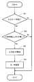
図10は、S32で行われる入力モード有効判断処理を示すフローチャートである。FIG. 10 is a flowchart showing the input mode validity determination process performed in S32.
S41にて、現在の入力モードの有効/無効の判断が行われる。入力モードが有効であるか無効であるかの情報は、RAM39に記憶されている。現在の入力モードが有効である場合(S41でNo)には、入力モード有効判断処理を終了する。In S41, it is determined whether the current input mode is valid / invalid. Information on whether the input mode is valid or invalid is stored in the
現在の入力モードが無効である場合(S41でYes)には、処理はS42に進む。S42では、すべてのホームポジションキー41がユーザによりタッチされているか否かが判断される。これにより、マイクロコンピュータ20は、ユーザの両人差し指が、QWERYキーのFとJを認識したと判断する。S42にて、ユーザがすべてのホームポジションキー41をタッチしたと判断された場合(S42でYes)には、S43に進む。S42にてすべてのホームポジションキー41をタッチしていないと判断された場合(S42でNo)には、入力モード有効判断処理を終了する。If the current input mode is invalid (Yes in S41), the process proceeds to S42. In S42, it is determined whether or not all
S43では、RAM39に記憶されているユーザのタッチ位置がホームポジションキー41上にとどまっている時間が、一定時間以上であるかの判断が行われる。一定時間以上とは、おおむね0.1s~2.0sのことである。ユーザが一定時間以上、ホームポジションキー41にタッチしている場合、マイクロコンピュータ20は、ユーザがホームポジションキー41を認識したと判断する。ユーザのタッチが一定時間以上ホームポジションキー41にとどまっていることを判断するために、S30でホームポジションキー41をタッチし続けている時間をRAM39に記憶しておくのが望ましい。In S43, it is determined whether the time during which the user's touch position stored in the
S43にて、ユーザが一定時間以上ホームポジションキー41をタッチしていないと判断された場合(S43でNo)には、入力モード有効判断処理を終了する。If it is determined in S43 that the user has not touched the home position key 41 for a certain period of time (No in S43), the input mode validity determination process is terminated.
S43にて、ユーザが一定時間以上ホームポジションキー41をタッチしていると判断された場合(S43でYes)には、S44にて入力モードを有効にしてRAM39に入力モードが有効であることを記憶する。そしてS45にてキーボードの色を変更し、視覚的にも入力モードが有効になったことを提示した上で、入力モード有効判断処理を終了する。If it is determined in S43 that the user has touched the home position key 41 for a certain period of time (Yes in S43), the input mode is validated in S44 and the input mode is valid in the
なお、視覚の変化以外にも、聴覚や触覚などにより入力モードの変更を提示するとなおよい。In addition to visual changes, it is better to present changes in input mode by hearing or touch.
なお、ユーザが一定時間以上ホームポジションキー41をタッチした後、ホームポジションキー41から指を離したときに、入力モードを有効にしてもよい。これにより、入力モードが無効から有効に切り替わるタイミングにおいて触れていたキーの入力が意図せず行われることを防止することができる。It should be noted that the input mode may be validated when the user touches the home position key 41 for a predetermined time or more and then releases the finger from the home position key 41. Thereby, it is possible to prevent unintentional input of the key touched at the timing when the input mode switches from invalid to valid.
図11は、S29(図9)における入力モード無効判断処理を示すフローチャートである。FIG. 11 is a flowchart showing the input mode invalidity determination process in S29 (FIG. 9).
S51にて、現在の入力モードの有効/無効の判断が行われる。入力モードが有効であるか無効であるかの情報は、RAM39に記憶されている。現在の入力モードが無効である場合には、入力モード無効判断処理を終了する。In S51, it is determined whether the current input mode is valid / invalid. Information on whether the input mode is valid or invalid is stored in the
現在の入力モードが有効である場合には、S52に進む。S52では、ユーザが操作領域45にタッチしていない時間が、一定時間以上であるかの判断を行う。ユーザが操作領域45にタッチしていない時間は、RAM39に記憶されている。一定時間以上とは、おおむね1s~10sのことである。ユーザが一定時間以上、操作領域45にタッチしていない場合、マイクロコンピュータ20は、ユーザがホームポジションキー41の位置を認識していないと判断する。ユーザが一定時間以上、操作領域45にタッチしていないことを判断するために、S21で、操作領域45にユーザがタッチしていない時間をRAM39に記憶しておくのが望ましい。If the current input mode is valid, the process proceeds to S52. In S52, it is determined whether the time during which the user does not touch the
S52にて、ユーザが操作領域45にタッチしていない時間が、一定時間に満たない場合(S52でNo)には、入力モード無効判断処理を終了する。In S52, when the time during which the user does not touch the
S52にて、ユーザが操作領域45にタッチしていない時間が、一定時間以上と判断された場合(S52でYes)には、S53にて入力モードを無効にし、入力モードが無効になったことをRAM39に記憶する。そして、S54にてキーボードの色を変更し、視覚的にも入力モードが無効になったことを提示した上で、入力モード無効判断処理を終了する。In S52, when it is determined that the time during which the user does not touch the
なお、視覚の変化以外にも、聴覚や触覚などにより入力モードの変更を提示してもよい。In addition to visual changes, input mode changes may be presented by hearing or touch.
(実施形態3)
次に、実施形態3に係る電子機器について説明する。実施形態3の電子機器10は、ユーザがホームポジション(基準領域の一例)を探すためにホームポジション以外のボタン(非基準領域の一例)をタッチしている際にも振動を発生させる点で、実施形態1の電子機器10と異なる。その他の構成や処理は実施形態1の電子機器10と同様であるため、同様の説明の繰り返しは省略する。以下、実施形態1の電子機器10と異なる点について説明する。(Embodiment 3)
Next, an electronic apparatus according to
図13は、実施形態3の電子機器10の処理を示すフローチャートである。S17において、ユーザがホームポジションをタッチしていない場合(S17でNo)、処理はS19に進む。S19では、振動制御部33が振動部13を制御することで、ユーザに触覚Cが与えられる。S17において、ユーザがホームポジションをタッチした場合(S17でYes)は、実施形態1と同様に触覚Aが与えられる。FIG. 13 is a flowchart illustrating processing of the
ユーザがホームポジションを探すためになぞり操作を行う際に、ホームポジション以外をタッチした場合と、ホームポジションをタッチした場合とで、ユーザは異なる触覚を得ることができる。これにより、ユーザは、自分がホームポジションをタッチしたか否かを知ることができる。また、ユーザがホームポジション以外をタッチした際に触覚Cがユーザに与えられるため、ユーザは自分がホームポジションを探しているということを認識することができる。When the user performs a tracing operation to search for a home position, the user can obtain different tactile sensations depending on whether the user touches a position other than the home position or the home position. Thereby, the user can know whether he / she touched the home position. In addition, since the tactile sense C is given to the user when the user touches a position other than the home position, the user can recognize that he / she is looking for the home position.
触覚Cの振動パターンは適宜設定される。振動パターンを異ならせる場合は、振動の周期や振幅等を変更すればよい。これにより、ユーザが振動を強く感じたり弱く感じたりすることができる。The vibration pattern of tactile C is set as appropriate. When different vibration patterns are used, the period and amplitude of vibration may be changed. Thereby, the user can feel the vibration strongly or weakly.
触覚A、触覚B、触覚Cの振動パターンの組み合わせは、以下のような組み合わせにすることができる。The combination of vibration patterns of tactile sense A, tactile sense B, and tactile sense C can be as follows.
<パターン1:A=B≠C>
触覚Aの振動パターンと触覚Bの振動パターンは互いに同じ振動パターンであり、かつ、触覚A(=触覚B)の振動パターンと触覚Cの振動パターンを互いに異なる振動パターンにしてもよい。これによりユーザは、自分がホームポジションを探す操作をしていることを認識することができる。<Pattern 1: A = B ≠ C>
The vibration pattern of the tactile sense A and the vibration pattern of the tactile sense B may be the same vibration pattern, and the vibration pattern of the tactile sense A (= tactile sense B) and the vibration pattern of the tactile sense C may be different from each other. Thereby, the user can recognize that he / she is performing an operation of searching for the home position.
<パターン2:A=C≠B>
触覚Aの振動パターンと触覚Cの振動パターンは互いに同じ振動パターンであり、かつ、触覚A(=触覚C)の振動パターンと触覚Bの振動パターンを互いに異なる振動パターンにしてもよい。これによりユーザは、ホームポジションを探しているのか、文字入力操作をしているのかを認識することができる。<Pattern 2: A = C ≠ B>
The vibration pattern of the tactile sense A and the vibration pattern of the tactile sense C may be the same vibration pattern, and the vibration pattern of the tactile sense A (= tactile sense C) and the vibration pattern of the tactile sense B may be different from each other. As a result, the user can recognize whether the user is searching for a home position or performing a character input operation.
<パターン3:A≠B=C>
触覚Bの振動パターンと触覚Cの振動パターンは互いに同じ振動パターンであり、かつ、触覚B(=触覚C)の振動パターンと触覚Aの振動パターンを互いに異なる振動パターンにしてもよい。これによりユーザは、自分がホームポジションを探し当てたことを認識することができる。<Pattern 3: A ≠ B = C>
The vibration pattern of the tactile sense B and the vibration pattern of the tactile sense C may be the same vibration pattern, and the vibration pattern of the tactile sense B (= tactile sense C) and the vibration pattern of the tactile sense A may be different from each other. Thereby, the user can recognize that he / she has found the home position.
<パターン4:A≠B≠C>
触覚Aの振動パターンと触覚Bの振動パターンと触覚Cの振動パターンの全てが互いに異なる振動パターンであってもよい。これによりユーザは、自分がどのような操作をしているのかを認識することができる。<Pattern 4: A ≠ B ≠ C>
The vibration pattern of the tactile sense A, the vibration pattern of the tactile sense B, and the vibration pattern of the tactile sense C may all be different from each other. As a result, the user can recognize what operation he / she is performing.
<実施形態のまとめ>
以上のとおり、本発明の実施形態に係る電子機器10は、表示部12と、タッチパネル11と、振動部13と、振動制御部33と、加速度センサ16とを備える。<Summary of Embodiment>
As described above, the
表示部12は、基準領域の一例であるホームポジションキー41と非基準領域の一例である一般キー42とを有する操作領域45を表示する。The
タッチパネル11は、少なくとも操作領域45を覆うように配置されている。The
振動部13は、報知部の一例であり、ユーザに対してユーザの操作状況を知らせる。The
振動制御部33は制御部の一例であり、振動部13を制御する。The
加速度センサ16は、判別部の一例であり、ユーザがタッチパネル11上で基準領域を探す第1操作と、操作領域45へのキー入力操作である第2操作とを判別する。The
そして、振動制御部33は、加速度センサ16により検出される結果に基づいて、振動部13を制御する。The
このような構成を備える電子機器10においては、加速度センサ16によりユーザの操作が判別され、それに応じた振動がユーザに与えられる。そのため、ユーザは、自らがどのような操作を行ったか、あるいは、自らの操作が電子機器10に認識されたかを知ることができる。その結果、ユーザは、電子機器10への入力を容易に行うことができる。In the
また、本実施形態に係る電子機器10は、表示部12と、タッチパネル11と、タッチパネル制御部31と、制御部の一例であるマイクロコンピュータ20とを備える。Moreover, the
表示部12は、基準領域の一例であるホームポジションキー41と非基準領域の一例である一般キー42とを有する操作領域45を表示する。The
タッチパネル11は、少なくとも操作領域45を覆うように配置されている。The
タッチパネル制御部31は、ユーザが基準領域の一例であるホームポジションキー41に接触したか、非基準領域の一例である一般キー42に接触したかを判別することができる。The touch
そして、ユーザがホームポジション41に接触した場合、マイクロコンピュータ20は、ユーザによるタッチパネル11への入力を有効にする。When the user touches the
電子機器10がこのような構成を備えることにより、ユーザがホームポジション41を探す操作を行った際に、誤って電子機器10にキー入力されてしまうことを防ぐことができる。したがって、ユーザは、電子機器10への入力を容易に行うことができる。By providing the
上述した電子機器10の動作は、ハードウエアによって実現されてもよいしソフトウエアによって実現されてもよい。そのような制御動作を実行させるプログラムは、例えばマイクロコンピュータ20の内蔵メモリやROM38に記憶される。また、そのようなコンピュータプログラムは、それが記録された記録媒体(光ディスク、半導体メモリ等)から電気機器10へインストールしてもよいし、インターネット等の電気通信回線を介してダウンロードしてもよい。The operation of the
(その他の実施形態)
本発明の実施形態として、実施形態1から3を例示したが、本発明はこれらに限定されない。例えば、以下のような実施形態も本発明に含まれる。(Other embodiments)
Although
報知部は、振動部13に限らない。例えば、報知部は、スピーカ17であり、音声によってユーザに情報を知らせる構成であってもよい。また、報知部は、光によりユーザに情報を知らせる構成であってもよい。このような構成は、例えば表示制御部32が表示部12を制御することで実現できる。また、報知部は、熱や電気ショックでユーザに情報を知らせる構成であってもよい。The notification unit is not limited to the
図12は、電子機器10の画面表示の一例であり、カーナビ、カーラジオ等の操作キーを示している。ユーザは、電子機器10の表示部12に表示された操作キーにタッチすることで、カーナビ、カーラジオを操作できる。表示部12には、ホームポジションキー41と、一般キー42と、エンターキー43と、終了キー44が表示されている。操作領域は、ホームポジションキー41と、一般キー42と、エンターキー43と、終了キー44を含む領域を示す。FIG. 12 is an example of a screen display of the
ユーザは、タッチパネルを見ることなく、ホームポジションキー41をなぞり操作により探し、そこからの相対位置により各種操作キーの位置を推測し、打鍵操作により一般キーを選択することで、音楽や映像情報の再生、停止、音量アップ、ダウン、チャンネルの変更などができる。The user searches for the home position key 41 without looking at the touch panel, estimates the position of various operation keys based on the relative position from the home position key 41, and selects a general key by key-pressing operation. Play, stop, volume up, down, channel change, etc.
判別部は、加速度センサ16に限らない。例えば、振動部13は圧電素子21を含む振動子であることを利用して、圧電素子21の振動を、圧電効果により電圧に変換し振動制御部33へその電圧を供給することもできる。振動制御部33に電圧検知機能を追加することで、ユーザの打鍵操作が振動部13により電圧に変換され、振動制御部33へ出力される。振動部13から振動制御部33に出力された電圧の情報に基づいてマイクロコンピュータ20はユーザが打鍵操作を行ったことを認識することができる。The determination unit is not limited to the
また、ユーザによる操作が、打鍵操作であるかなぞり操作であるかの判別は、タッチパネル制御部31によっても行うことができる。例えば、タッチパネル11が抵抗膜式である場合、上下層の接触面積は抵抗値によって認識可能であるので、その接触面積の時間変化の割合から、なぞり操作であるか打鍵操作であるかを判断できる。The touch
タッチパネル11が静電容量方式の場合も、ユーザの指のタッチパネル11への接触面積、およびユーザの指がタッチパネル11に近づいたかどうかは、静電容量の変化により認識可能である。その静電容量の変化により、なぞり操作であるか打鍵操作であるかを判断できる。つまり、なぞり操作である場合は、静電容量の変化が小さく、打鍵操作の場合には、静電容量の変化が大きい。Even when the
実施形態1から3では、電子機器の一例としてタブレット型の情報端末機器を用いて説明したが、本発明の電子機器はこれには限らない。例えば、携帯電話、PDA、ゲーム機、カーナビゲーション、ATMなど、タッチパネルを備える電子機器に本発明は適用される。
実施形態1から3では、タッチパネルとして表示部12の表示面の全面を覆うものを例示したが、これには限らない。例えば、表示面の中央部のみにタッチパネル機能を有し、周辺部はタッチパネル機能を有する部分が覆っていない状態でもよい。要するに、少なくとも表示部の入力操作領域を覆うものであればよい。In
実施形態1から3では、タッチパネル11と表示部12は別体となっていたが、これには限定されない。例えば、タッチパネル11が表示部12に接着されていてもよい。あるいは、表示部12がタッチ位置を検出する機能を有していてもよい。要するに、タッチ位置を検出することができればよい。In
実施形態1から3では、タッチパネル11を振動させていたが、これに限定されない。例えば、タッチパネル11の外側にカバーガラスが配置されている場合は、これを振動させてもよい。要するに、ユーザが接触する部材を振動させることができればよい。In
本発明は、例えばユーザによるタッチ操作が可能な電子機器に有用である。The present invention is useful for an electronic device that can be touched by a user, for example.
10 電子機器
11 タッチパネル
12 表示部
13 振動部
14 筐体
15 カメラ
16 加速度センサ
17 スピーカ
18 スペーサ
19 回路基板
20 マイクロコンピュータ
21 圧電素子
22 シム板DESCRIPTION OF
Claims (12)
Translated fromJapanese前記表示部の表示面側に設けられたタッチパネルと、
ユーザに対して、前記ユーザの操作状況を知らせる報知部と、
前記報知部の動作を制御する制御部と、
前記タッチパネル上で前記ユーザが前記基準領域を探す第1操作と、前記操作領域へのキー入力操作である第2操作とを判別する判別部と、
を備え、
前記制御部は、前記判別部の判別結果に基づいて前記報知部の動作を制御する、電子機器。A display unit for displaying an operation area having a reference area and a non-reference area;
A touch panel provided on the display surface side of the display unit;
A notification unit that informs the user of the operation status of the user;
A control unit for controlling the operation of the notification unit;
A discriminator for discriminating between a first operation in which the user searches the reference area on the touch panel and a second operation that is a key input operation to the operation area;
With
The said control part is an electronic device which controls operation | movement of the said alerting | reporting part based on the discrimination | determination result of the said discrimination | determination part.
前記第2操作は、前記タッチパネル上での打鍵操作である、請求項1から3のいずれかに記載の電子機器。The first operation is an operation in which the contact position of the user on the touch panel continuously changes,
The electronic device according to claim 1, wherein the second operation is a keystroke operation on the touch panel.
前記制御部は、前記第2操作において前記ユーザが前記操作領域に接触したときに、前記第1の振動パターンとは異なる第2の振動パターンで前記振動部が振動するように制御する、請求項10に記載の電子機器。The control unit controls the vibration unit to vibrate in a first vibration pattern when the user contacts the reference region in the first operation,
The control unit controls the vibration unit to vibrate with a second vibration pattern different from the first vibration pattern when the user touches the operation region in the second operation. 10. The electronic device according to 10.
前記プログラムは、
前記タッチパネル上で前記ユーザが基準領域を探す第1操作と、操作領域へのキー入力操作である第2操作とを判別するステップと、
前記判別結果に基づいて前記ユーザに知らせる動作を制御するステップと、
を前記電子機器に実行させるプログラム。A program for causing an electronic device to execute an operation for notifying the user of the operation status of the user on the touch panel,
The program is
Discriminating between a first operation where the user searches for a reference area on the touch panel and a second operation which is a key input operation to the operation area;
Controlling an operation to inform the user based on the determination result;
A program for causing the electronic device to execute.
Priority Applications (2)
| Application Number | Priority Date | Filing Date | Title |
|---|---|---|---|
| JP2012528169AJP5496337B2 (en) | 2011-02-04 | 2012-01-05 | Electronics |
| US13/950,751US9557815B2 (en) | 2011-02-04 | 2013-07-25 | Electronic device |
Applications Claiming Priority (2)
| Application Number | Priority Date | Filing Date | Title |
|---|---|---|---|
| JP2011-022377 | 2011-02-04 | ||
| JP2011022377 | 2011-02-04 |
Related Child Applications (1)
| Application Number | Title | Priority Date | Filing Date |
|---|---|---|---|
| US13/950,751ContinuationUS9557815B2 (en) | 2011-02-04 | 2013-07-25 | Electronic device |
Publications (1)
| Publication Number | Publication Date |
|---|---|
| WO2012105158A1true WO2012105158A1 (en) | 2012-08-09 |
Family
ID=46602388
Family Applications (1)
| Application Number | Title | Priority Date | Filing Date |
|---|---|---|---|
| PCT/JP2012/000039WO2012105158A1 (en) | 2011-02-04 | 2012-01-05 | Electronic device |
Country Status (3)
| Country | Link |
|---|---|
| US (1) | US9557815B2 (en) |
| JP (1) | JP5496337B2 (en) |
| WO (1) | WO2012105158A1 (en) |
Cited By (9)
| Publication number | Priority date | Publication date | Assignee | Title |
|---|---|---|---|---|
| JP2013250710A (en)* | 2012-05-31 | 2013-12-12 | Kyocera Document Solutions Inc | Input device |
| JP2014061753A (en)* | 2012-09-20 | 2014-04-10 | Yuhshin Co Ltd | On-vehicle equipment operating device |
| JP2014204137A (en)* | 2013-04-01 | 2014-10-27 | レノボ・シンガポール・プライベート・リミテッド | Input system of touch type display and display method for input panel |
| JP2015111479A (en)* | 2015-03-25 | 2015-06-18 | 京セラドキュメントソリューションズ株式会社 | Input device |
| EP2907006A1 (en)* | 2012-10-10 | 2015-08-19 | Microsoft Technology Licensing, LLC | Provision of haptic feedback for localization and data input |
| JP2016057856A (en)* | 2014-09-10 | 2016-04-21 | 三菱電機株式会社 | Haptic control system and haptic control method |
| JP2018125021A (en)* | 2012-08-24 | 2018-08-09 | イマージョン コーポレーションImmersion Corporation | Context-dependent haptic confirmation system |
| JP2020523720A (en)* | 2017-06-07 | 2020-08-06 | ケアテク インターナショナル ゲーエムベーハー | Input and output method of text composed of characters |
| JP2021048461A (en)* | 2019-09-18 | 2021-03-25 | 株式会社東芝 | Optical imaging apparatus |
Families Citing this family (5)
| Publication number | Priority date | Publication date | Assignee | Title |
|---|---|---|---|---|
| US9268424B2 (en)* | 2012-07-18 | 2016-02-23 | Sony Corporation | Mobile client device, operation method, recording medium, and operation system |
| US10684774B2 (en)* | 2014-09-09 | 2020-06-16 | Touchtype Limited | Systems and methods for multiuse of keys for virtual keyboard and generating animation associated with a key |
| JP6097268B2 (en)* | 2014-12-02 | 2017-03-15 | レノボ・シンガポール・プライベート・リミテッド | Input device, software keyboard display method thereof, and computer-executable program |
| JP7142196B2 (en)* | 2016-12-27 | 2022-09-27 | パナソニックIpマネジメント株式会社 | ELECTRONIC DEVICE, TABLET TERMINAL, INPUT CONTROL METHOD, AND PROGRAM |
| CN115104080B (en)* | 2020-11-30 | 2025-01-21 | 京东方科技集团股份有限公司 | Display panel and driving method thereof, and display device |
Citations (2)
| Publication number | Priority date | Publication date | Assignee | Title |
|---|---|---|---|---|
| JP2005129072A (en)* | 2004-11-05 | 2005-05-19 | Oki Electric Ind Co Ltd | Automatic transaction device and input unit |
| JP2010244253A (en)* | 2009-04-03 | 2010-10-28 | Sony Corp | Information processing apparatus, notification method, and program |
Family Cites Families (19)
| Publication number | Priority date | Publication date | Assignee | Title |
|---|---|---|---|---|
| JP4484255B2 (en)* | 1996-06-11 | 2010-06-16 | 株式会社日立製作所 | Information processing apparatus having touch panel and information processing method |
| JP3987182B2 (en)* | 1998-01-26 | 2007-10-03 | Idec株式会社 | Information display device and operation input device |
| JP2001356861A (en)* | 2000-06-13 | 2001-12-26 | Olympus Optical Co Ltd | Tactile sense presenting device and method |
| JP3949912B2 (en) | 2000-08-08 | 2007-07-25 | 株式会社エヌ・ティ・ティ・ドコモ | Portable electronic device, electronic device, vibration generator, notification method by vibration and notification control method |
| JP3673191B2 (en)* | 2001-06-27 | 2005-07-20 | 沖電気工業株式会社 | Automatic transaction equipment |
| JP3888099B2 (en)* | 2001-08-17 | 2007-02-28 | 富士ゼロックス株式会社 | Touch panel device |
| JP4500485B2 (en)* | 2002-08-28 | 2010-07-14 | 株式会社日立製作所 | Display device with touch panel |
| JP2004110388A (en)* | 2002-09-18 | 2004-04-08 | Sharp Corp | Device with touch panel |
| US20050085215A1 (en)* | 2003-10-21 | 2005-04-21 | Nokia Corporation | Method and related apparatus for emergency calling in a touch screen mobile phone from a touch screen and keypad lock active state |
| JP4338513B2 (en) | 2003-12-26 | 2009-10-07 | アルパイン株式会社 | Input control apparatus and input receiving method |
| US7659887B2 (en)* | 2005-10-20 | 2010-02-09 | Microsoft Corp. | Keyboard with a touchpad layer on keys |
| US8270946B2 (en)* | 2006-02-08 | 2012-09-18 | Nec Corporation | Mobile terminal and method for controlling lock and unlock functions by means of contact sensor |
| US20070236474A1 (en) | 2006-04-10 | 2007-10-11 | Immersion Corporation | Touch Panel with a Haptically Generated Reference Key |
| JP2008033739A (en) | 2006-07-31 | 2008-02-14 | Sony Corp | Touch screen interaction method and apparatus based on tactile force feedback and pressure measurement |
| JP4358846B2 (en)* | 2006-08-15 | 2009-11-04 | 株式会社エヌ・ティ・ティ・ドコモ | Mobile terminal device and operation support method thereof |
| US8127254B2 (en)* | 2007-06-29 | 2012-02-28 | Nokia Corporation | Unlocking a touch screen device |
| JP4897596B2 (en)* | 2007-07-12 | 2012-03-14 | ソニー株式会社 | INPUT DEVICE, STORAGE MEDIUM, INFORMATION INPUT METHOD, AND ELECTRONIC DEVICE |
| US9041660B2 (en)* | 2008-12-09 | 2015-05-26 | Microsoft Technology Licensing, Llc | Soft keyboard control |
| US8621380B2 (en)* | 2010-01-06 | 2013-12-31 | Apple Inc. | Apparatus and method for conditionally enabling or disabling soft buttons |
- 2012
- 2012-01-05WOPCT/JP2012/000039patent/WO2012105158A1/enactiveApplication Filing
- 2012-01-05JPJP2012528169Apatent/JP5496337B2/ennot_activeExpired - Fee Related
- 2013
- 2013-07-25USUS13/950,751patent/US9557815B2/enactiveActive
Patent Citations (2)
| Publication number | Priority date | Publication date | Assignee | Title |
|---|---|---|---|---|
| JP2005129072A (en)* | 2004-11-05 | 2005-05-19 | Oki Electric Ind Co Ltd | Automatic transaction device and input unit |
| JP2010244253A (en)* | 2009-04-03 | 2010-10-28 | Sony Corp | Information processing apparatus, notification method, and program |
Cited By (11)
| Publication number | Priority date | Publication date | Assignee | Title |
|---|---|---|---|---|
| JP2013250710A (en)* | 2012-05-31 | 2013-12-12 | Kyocera Document Solutions Inc | Input device |
| JP2018125021A (en)* | 2012-08-24 | 2018-08-09 | イマージョン コーポレーションImmersion Corporation | Context-dependent haptic confirmation system |
| JP2014061753A (en)* | 2012-09-20 | 2014-04-10 | Yuhshin Co Ltd | On-vehicle equipment operating device |
| EP2907006A1 (en)* | 2012-10-10 | 2015-08-19 | Microsoft Technology Licensing, LLC | Provision of haptic feedback for localization and data input |
| JP2014204137A (en)* | 2013-04-01 | 2014-10-27 | レノボ・シンガポール・プライベート・リミテッド | Input system of touch type display and display method for input panel |
| JP2016057856A (en)* | 2014-09-10 | 2016-04-21 | 三菱電機株式会社 | Haptic control system and haptic control method |
| JP2015111479A (en)* | 2015-03-25 | 2015-06-18 | 京セラドキュメントソリューションズ株式会社 | Input device |
| JP2020523720A (en)* | 2017-06-07 | 2020-08-06 | ケアテク インターナショナル ゲーエムベーハー | Input and output method of text composed of characters |
| JP2021048461A (en)* | 2019-09-18 | 2021-03-25 | 株式会社東芝 | Optical imaging apparatus |
| JP7321857B2 (en) | 2019-09-18 | 2023-08-07 | 株式会社東芝 | optical imaging device |
| US11977182B2 (en) | 2019-09-18 | 2024-05-07 | Kabushiki Kaisha Toshiba | Optical imaging apparatus, robot hand, moving body, and LiDAR apparatus |
Also Published As
| Publication number | Publication date |
|---|---|
| US20130307804A1 (en) | 2013-11-21 |
| JP5496337B2 (en) | 2014-05-21 |
| US9557815B2 (en) | 2017-01-31 |
| JPWO2012105158A1 (en) | 2014-07-03 |
Similar Documents
| Publication | Publication Date | Title |
|---|---|---|
| JP5496337B2 (en) | Electronics | |
| JP5615421B2 (en) | Electronics | |
| CN102498458B (en) | input device | |
| JP4672075B2 (en) | Input device | |
| JP5738413B2 (en) | Electronics | |
| EP2383631A1 (en) | Hand-held mobile device and method for operating the hand-held mobile device | |
| JP6246640B2 (en) | Electronics | |
| CN1582465A (en) | Method and device for providing tactile sensation | |
| JP2011048686A (en) | Input apparatus | |
| JP5718475B2 (en) | Tactile presentation device | |
| JP2005149197A (en) | Input device, information processor, remote controller and method of controlling input device | |
| JP5437786B2 (en) | Tactile presentation device | |
| WO2012102048A1 (en) | Electronic device | |
| JP2017111462A (en) | Tactile sensation presentation apparatus and tactile sensation presentation method | |
| WO2013061499A1 (en) | Input device and control method for input device | |
| KR20120115159A (en) | Tactile feedback method and apparatus | |
| JP5587596B2 (en) | Tactile presentation device | |
| JP6120898B2 (en) | Electronic device and control method of electronic device | |
| JP5588023B2 (en) | Electronics | |
| JP2009230175A (en) | Key input device | |
| KR20100107996A (en) | Pen type tactile representive device having touch face and tactile interface system using thereof | |
| JP5143881B2 (en) | Tactile sensation presentation apparatus and control method of tactile sensation presentation apparatus | |
| WO2012108184A1 (en) | Electronic device and computer program | |
| KR101715394B1 (en) | Apparatus with touch window unit |
Legal Events
| Date | Code | Title | Description |
|---|---|---|---|
| WWE | Wipo information: entry into national phase | Ref document number:2012528169 Country of ref document:JP | |
| 121 | Ep: the epo has been informed by wipo that ep was designated in this application | Ref document number:12741873 Country of ref document:EP Kind code of ref document:A1 | |
| NENP | Non-entry into the national phase | Ref country code:DE | |
| 122 | Ep: pct application non-entry in european phase | Ref document number:12741873 Country of ref document:EP Kind code of ref document:A1 |