WO2012070822A2 - Bone harvesting device and driving device thereof - Google Patents
Bone harvesting device and driving device thereofDownload PDFInfo
- Publication number
- WO2012070822A2 WO2012070822A2PCT/KR2011/008892KR2011008892WWO2012070822A2WO 2012070822 A2WO2012070822 A2WO 2012070822A2KR 2011008892 WKR2011008892 WKR 2011008892WWO 2012070822 A2WO2012070822 A2WO 2012070822A2
- Authority
- WO
- WIPO (PCT)
- Prior art keywords
- bone
- operating rod
- movable body
- rotating plate
- driving
- Prior art date
Links
- 210000000988bone and boneAnatomy0.000titleclaimsabstractdescription177
- 238000003306harvestingMethods0.000titleclaimsabstractdescription45
- 230000004308accommodationEffects0.000claimsabstract2
- 238000000605extractionMethods0.000claimsdescription38
- 238000003780insertionMethods0.000claimsdescription19
- 230000037431insertionEffects0.000claimsdescription19
- 238000000034methodMethods0.000claimsdescription7
- 238000004873anchoringMethods0.000claimsdescription4
- 239000000284extractSubstances0.000description3
- 239000007769metal materialSubstances0.000description3
- 238000005192partitionMethods0.000description3
- 238000005070samplingMethods0.000description3
- 230000008878couplingEffects0.000description2
- 238000010168coupling processMethods0.000description2
- 238000005859coupling reactionMethods0.000description2
- 238000012986modificationMethods0.000description2
- 230000004048modificationEffects0.000description2
- 239000007787solidSubstances0.000description2
- 238000002054transplantationMethods0.000description2
- 241001272720Medialuna californiensisSpecies0.000description1
- 241001465754MetazoaSpecies0.000description1
- 238000002316cosmetic surgeryMethods0.000description1
- 238000009434installationMethods0.000description1
- 231100000957no side effectToxicity0.000description1
- 229910052755nonmetalInorganic materials0.000description1
- 238000007790scrapingMethods0.000description1
- 210000001519tissueAnatomy0.000description1
Images


Classifications
- A—HUMAN NECESSITIES
- A61—MEDICAL OR VETERINARY SCIENCE; HYGIENE
- A61B—DIAGNOSIS; SURGERY; IDENTIFICATION
- A61B17/00—Surgical instruments, devices or methods
- A61B17/16—Instruments for performing osteoclasis; Drills or chisels for bones; Trepans
- A61B17/1635—Instruments for performing osteoclasis; Drills or chisels for bones; Trepans for grafts, harvesting or transplants
- A—HUMAN NECESSITIES
- A61—MEDICAL OR VETERINARY SCIENCE; HYGIENE
- A61C—DENTISTRY; APPARATUS OR METHODS FOR ORAL OR DENTAL HYGIENE
- A61C8/00—Means to be fixed to the jaw-bone for consolidating natural teeth or for fixing dental prostheses thereon; Dental implants; Implanting tools
- A61C8/0089—Implanting tools or instruments
- A61C8/0092—Implanting tools or instruments for sinus lifting
Definitions
- Figure 3is a schematic overall perspective view of a bone harvesting device and a drive device according to a first embodiment of the present invention
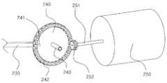
- FIG. 15is a schematic exploded perspective view illustrating a connection relationship between a second operating rod, a rotating plate, and a driving motor of FIG. 14;
- Figure 3is a schematic overall perspective view of the bone harvesting device and its driving device according to the present embodiment.
- the rotating plate 240is rotated by obtaining a driving force from the first shaft bar 251a, and the first shaft bar 251a is connected to the second shaft bar 251b.
- the driving motor 250is connected to the wire 290 to receive external power through the wire 290.
Landscapes
- Health & Medical Sciences (AREA)
- Surgery (AREA)
- Life Sciences & Earth Sciences (AREA)
- Engineering & Computer Science (AREA)
- Heart & Thoracic Surgery (AREA)
- Nuclear Medicine, Radiotherapy & Molecular Imaging (AREA)
- Oral & Maxillofacial Surgery (AREA)
- Dentistry (AREA)
- Transplantation (AREA)
- Biomedical Technology (AREA)
- Orthopedic Medicine & Surgery (AREA)
- Medical Informatics (AREA)
- Molecular Biology (AREA)
- Animal Behavior & Ethology (AREA)
- General Health & Medical Sciences (AREA)
- Public Health (AREA)
- Veterinary Medicine (AREA)
- Orthopedics, Nursing, And Contraception (AREA)
- Prostheses (AREA)
Abstract
Description
Translated fromKorean본 발명은 뼈채취장치에 관한 것으로, 더욱 구체적으로는 사람이나 동물의 다양한 형태와 종류의 뼈들로부터 원하는 양의 뼈를 쉽게 자동으로 채취할 수 있는 뼈채취장치 및 그 구동장치에 관한 것이다.The present invention relates to a bone harvesting device, and more particularly to a bone harvesting device and its driving device that can easily automatically collect the desired amount of bone from various types and types of bones of humans or animals.
치과나 성형외과 시술에서 뼈가 부족한 경우 부족한 뼈를 대신하기 위해 뼈 이식을 하게 된다. 뼈 이식은 자가뼈를 사용하여 이루어지는 것이 바람직하나 자가뼈를 얻는 것이 쉽지 않아 통상 인조뼈나 합성뼈를 사용하고 있는 데, 인조뼈나 합성뼈는 이식 후 생체 부작용이 생기거나 조직이 달라 이식이 제대로 이루어지지 않는 문제가 있다.If a bone is lacking in a dental or plastic surgery procedure, a bone graft is performed to replace the missing bone. Although bone graft is preferably done using autologous bones, it is not easy to obtain autologous bones, so artificial bones or synthetic bones are usually used. There is no problem.
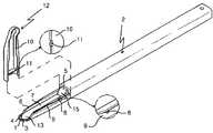
이러한 이유로 부족한 뼈의 양이 많지 않을 경우 소량의 자가뼈를 채취하기 위한 기구가 한국등록특허 제10-0428933호의 「골채취용구」에 개시되어 있고, 그 대표 도면이 도 1 및 도 2에 도시되어 있다.For this reason, a mechanism for collecting a small amount of autologous bone when the amount of bone is insufficient is disclosed in the "bone harvesting tool" of Korean Patent No. 10-0428933, the representative drawings are shown in Figures 1 and 2 have.
도 1에 도시된 바와 같이, 종래의 골채취용구는 손잡이(2)의 맨앞에 칼날(1)이 내측으로 70°~ 90°기울어지게 일체로 사출성형되어 있고, 이 칼날(1)과 약간 떨어지게 반원형의 돌기(3)가 형성되어 이들 사이에 골통과홀(4)이 형성되어 있다.As shown in Fig. 1, the conventional bone picking tool is integrally injection-molded so that the
반원형의 돌기(3) 위쪽에는 칼날(1)에 의해 긁혀진 골이 저장되는 저장공간(7)이 마련되고 골이 이 저장공간(7)으로 쉽게 이동되도록 저장공간(7)과 통하는 경사면(13)이 반원형의 돌기(3) 주변에 형성되어 있다.Above the semi-circular projection 3 is provided a storage space 7 for storing the bone scratched by the
저장공간(7)의 좌우측에는 격벽(5)이 형성되어 공간을 한정해 주고 있고, 이 격벽(5)에는 커버(12)가 덮혀지게 된다. 이때, 격벽(5)에 형성된 록킹돌기(8)와 커버(12)에 형성된 록킹홈(11)이 서로 결합되게 된다.
상술한 구성을 갖는 종래의 골채취용구는 도 2에 도시된 바와 같이 술자가 한 손으로 잡고 칼날이 뼈에 닿도록 용구를 뼈에 갖다 댄 후 손을 당기는 동작을 통해 뼈를 긁어 채취하게 된다.Conventional bone harvesting device having the above-described configuration is as shown in Figure 2 by the operator to grab the bone through the operation to pull the hand after holding the tool to the bone so that the blade touches the bone with one hand.
그러나 종래의 골채취용구를 손의 당기는 힘을 사용하여 수동으로 채취하기 때문에 채취되는 뼈의 상태가 고르지 않고 그 양이 아주 적었을 뿐만 아니라 술자가 숙련자가 아닌 경우 채취하는 작업이 어렵고 매우 힘들었으며 시간도 많이 걸렸다.However, because the bone is collected unevenly and the amount is very small because the bone collecting equipment is collected manually using the pulling force of the hand, and it is difficult and very difficult to collect when the operator is not skilled. It also took a lot.
본 발명은 상술한 종래기술의 문제점을 해결하기 위하여 창안된 것으로, 본 발명의 해결하고자 하는 과제는 앵커날이 선단에 마련되는 고정연결체를 구동장치에 고정되게 연결하고 뼈를 긁어내는 뼈채취날이 선단에 마련되는 가동체를 구동장치의 구동력에 의해 전후운동이 가능하게 고정연결체 속에 연결함으로써 원하는 양만큼의 고른 상태의 자가뼈를 자동으로 빠르게 채취할 수 있는 뼈채취장치 및 그 구동장치를 제공하는 것이다.The present invention has been made to solve the above-mentioned problems of the prior art, the problem to be solved of the present invention is to connect the fixed connector provided at the tip of the anchor blade fixedly to the drive device and scrape bone bone By connecting the movable body provided at the tip to the fixed connecting body by the driving force of the driving device so that the back and forth movement can be performed, the bone collecting device and the driving device which can automatically collect the autogenous bone in the desired amount as quickly as desired. To provide.
상술한 본 발명의 과제를 달성하기 위하여, 본 발명은 가동체수용공간이 형성되는 고정연결체와, 선단에 뼈채취날이 고정되게 마련되고 고정연결체 속에 전후진운동이 가능하게 연결되며 채취된 뼈가 수집되는 채취뼈수집공간이 형성되는 가동체와, 한 쪽으로 개방된 채취뼈수집공간을 막도록 가동체에 분리 가능하게 설치되는 덮개판을 포함하는 것을 특징으로 하는 뼈채취장치를 제공한다.In order to achieve the above object of the present invention, the present invention is a fixed connecting body and the movable body receiving space is formed, the bone extraction blade is provided to be fixed to the front end and the forward and backward movement in the fixed connecting body is collected and It provides a bone harvesting device comprising a movable plate is formed in the collecting bone collecting space is collected bone, and a cover plate detachably installed on the movable body to prevent the collecting bone collecting space opened to one side.
본 실시예의 뼈채취장치는 고정연결체가 선단에 고정연결체를 채취하고자 하는 뼈의 표면에 앵커링시키는 앵커날이 고정되게 마련되는 것을 특징으로 하고, 고정연결체가 선단에 앵커날이 꽉 끼워지는 끼움홈이 형성되는 것을 다른 특징으로 하고, 앵커날이 끼움홈에 꽉 끼워지는 끼움부, 끼움부에 바깥쪽으로 경사지게 일체로 형성되는 경사부 및 경사부 끝단에 일체로 형성되는 다수의 뾰족돌기날들로 구성되는 것을 또 다른 특징으로 하고, 경사부가 고정연결체의 바닥수평면에 대해 110°~ 160°범위의 경사각을 갖는 것을 또 다른 특징으로 한다.Bone harvesting device of the present embodiment is characterized in that the anchoring blade is fixed to the anchoring surface is fixed to the surface of the bone to be fixed to the fixed connector to the front end, the fixed connector is fitted into the anchor blade is tightly fitted to the tip This is characterized in that it is formed, the anchor blade is tightly fitted into the fitting groove, the inclined portion is formed integrally inclined outwardly to the fitting portion and composed of a plurality of pointed blades integrally formed on the end of the inclined portion It is another feature that the inclined portion has an inclination angle in the range of 110 ° to 160 ° with respect to the bottom horizontal plane of the fixed connector is another feature.
또한 본 실시예의 뼈채취장치는 고정연결체가 안쪽면에 "T"형 지지대가 마련되고 가동체가 상면에 상기 "T"형 지지대를 따라 가동체의 전후진운동을 안내하는 탄성력이 우수한 안내레일이 마련되는 것을 특징으로 하고, "T"형 지지대가 폭방향으로 안내레일삽입홈이 형성되고, 안내레일이 반트랙모양을 갖고 "T"형 지지대가 지나가는 안내홈이 길이방향으로 길게 형성되며 안측이 안내레일삽입홈에 끼워지는 것을 다른 특징으로 하고, 안내레일이 "T"형 지지대가 관통되게 끼워지는 관통공이 안내홈과 직교하거나 교차하게 형성되는 것을 또 다른 특징으로 한다.In addition, the bone collecting device of the present embodiment is provided with a guide rail having excellent elastic force for guiding the forward and backward movement of the movable body along the "T" type support on the upper surface and the movable body is provided on the inner side of the fixed connector. Characterized in that, the guide rail insertion groove is formed in the width direction of the "T" type support, the guide rail has a half-track shape and the guide groove through which the "T" type support passes is formed long in the longitudinal direction and the inner side guides. Another feature is that the rail is inserted into the groove, and the guide rail is formed so that the through-hole into which the "T" type support is inserted is orthogonal to or crosses the guide groove.
또한 본 실시예의 뼈채취장치는 가동체가 선단에 뼈채취날이 꽉 끼워지는 끼움홈이 형성되는 것을 특징으로 하고, 뼈채취날이 끼움홈에 꽉 끼워지는 끼움부, 끼움부에 안쪽으로 경사지게 일체로 형성되는 경사부 및 경사부의 끝단에 일체로 형성되는 반달모양의 날부로 구성되는 것을 다른 특징으로 하고, 경사부가 가동체의 바닥수평면에 대해 30°~ 110°범위의 경사각을 갖는 것을 또 다른 특징으로 한다.In addition, the bone picking device of the present embodiment is characterized in that the movable body is fitted with a fitting groove in which the bone picking blade is tightly fitted at the tip, and the bone picking blade is tightly fitted in the fitting groove, inclined inwardly integrally. Another feature is that the inclined portion is formed of a vandal-shaped blade integrally formed at the end of the inclined portion, the inclined portion has an inclination angle of 30 ° ~ 110 ° with respect to the bottom horizontal surface of the movable body do.
또한 본 실시예의 뼈채취장치는 덮개판이 가동체에 형성된 덮개판삽입홈에 끼워지는 것을 특징으로 하고, 덮개판이 폭방향으로 다수의 홈이 형성된 당김편이 뒤쪽에 일체로 마련되는 것을 다른 특징으로 한다.In addition, the bone extraction device of the present embodiment is characterized in that the cover plate is fitted into the cover plate insertion groove formed in the movable body, the cover plate is characterized in that the pull piece formed with a plurality of grooves in the width direction is integrally provided at the rear.
본 발명은 또한 상술한 뼈채취장치를 구동하기 위한 장치로, 고정연결체와 선택적으로 고정되게 연결되는 본체와, 본체 속에 마련되고 가동체와 선택적으로 고정되게 연결되어 상기 가동체를 전후진시키는 작동봉와, 본체 속에 마련되고 작동봉에 회전 가능하게 연결되어 작동봉을 전후진시키는 회전판와, 본체 속에 마련되고 회전판에 회전력을 인가하는 구동모터를 포함하는 것을 특징으로 하는 뼈채취장치의 구동장치를 제공한다.The present invention also provides a device for driving the above-described bone harvesting device, the main body is selectively fixedly connected to the fixed connection body, the operation is provided in the main body and selectively fixedly connected to the movable body to move the movable body forward and backward And a rod, a rotating plate provided in the main body and rotatably connected to the operating rod to move the operating rod forward and backward, and a driving motor provided in the main body and applying rotational force to the rotating plate. .
본 실시예의 구동장치는 본체가 일자로 형성되거나 또는 10°~ 40°구부러지게 형성되는 것과, 작동봉이 일단부가 가동체에 연결되는 제1작동봉 및 일단부가 제1작동봉의 타단부에 회전 가능하게 연결되고 타단부가 회전판에 회전 가능하게 연결되는 제2작동봉으로 구성되는 것을 특징으로 하고, 제1작동봉의 일단부가 십자모양인 것과, 제1작동봉의 원할한 운동을 돕기 위해 본체 속에 마련되는 제1작동봉을 지지하는 베어링을 더 포함하는 것을 다른 특징으로 한다.In the driving device of the present embodiment, the main body is formed to be straight or bent from 10 ° to 40 °, and the actuating rod is rotatably connected to the other end of the first actuating rod and the first actuating rod having one end connected to the movable body. And a second operating rod connected to the other end and rotatably connected to the rotating plate, wherein one end of the first operating rod is cross-shaped, and an article provided in the main body to help smooth movement of the first operating rod. 1 further comprises a bearing for supporting the operating rod.
또한 본 실시예의 구동장치는 회전판이 환형의 종동기어가 일체로 돌출되게 형성되고 중앙에 회전판을 회전 가능하게 지지하기 위한 회전축이 형성되며 구동모터이 구동축에 환형의 종동기어와 기어 결합되는 구동기어가 고정되게 결합되는 것과, 구동모터에 전원을 공급하기 위해 본체 속에 마련되는 배터리를 더 포함하는 것을 특징으로 하고, 배터리가 교체식 또는 충전식인 것을 다른 특징으로 하고, 충전식이 접촉식 또는 비접촉식인 것을 또 다른 특징으로 한다.In addition, the driving device of the present embodiment is formed such that the rotating plate is formed so that the annular driven gear integrally protrudes, and a rotating shaft for rotatably supporting the rotating plate is formed at the center thereof, and the driving gear in which the driving motor is geared with the annular driven gear is fixed to the driving shaft. And a battery provided in the main body for supplying power to the drive motor, wherein the battery is another replaceable or rechargeable battery, and the rechargeable battery is contact or noncontact battery. It features.
또한 본 실시예의 구동장치는 구동모터와 연결되게 본체에 마련되어 구동모터의 구동력으로부터 산정될 수 있는 뼈 채취양, 뼈 채취깊이, 뼈 채취상태 등을 표시하는 표시장치를 더 포함하는 것과, 구동모터와 연결되게 본체에 마련되어 구동모터의 작동 및 속도와 세기를 조절하는 조작버튼을 더 포함하는 것을 특징으로 한다.In addition, the driving device of the present embodiment further comprises a display device which is provided in the main body to be connected to the driving motor to display the bone extraction amount, bone extraction depth, bone extraction state, etc. can be calculated from the driving force of the drive motor, and the drive motor and It is characterized in that it further comprises a control button provided on the body to adjust the operation and speed and strength of the drive motor.
또한 본 발명은 또한 상술한 뼈채취장치를 구동하기 위한 장치로, 고정연결체와 선택적으로 고정되게 연결되는 제1본체와, 제1본체 속에 마련되고 가동체와 선택적으로 고정되게 연결되어 가동체를 전후진시키는 작동봉과, 제1본체 속에 마련되고 작동봉에 회전 가능하게 연결되어 작동봉을 전후진시키는 회전판과, 제1본체와 선택적으로 고정되게 연결되는 제2본체와, 외부 전원과 전기적으로 연결되도록 제2본체 속에 마련되고 회전판에 회전력을 인가하는 구동모터를 포함하는 것을 특징으로 하는 뼈채취장치의 구동장치를 제공한다.In another aspect, the present invention is a device for driving the above-described bone harvesting device, the first body is selectively fixedly connected to the fixed connection body, and provided in the first body and selectively fixedly connected to the movable body to move the movable body An actuating rod fore and aft advancing, a rotating plate provided in the first body and rotatably connected to the actuating rod for advancing and actuating the actuating rod, a second main body selectively fixedly connected to the first main body, and electrically connected to the external power It is provided in the second body to provide a drive device of the bone harvesting device comprising a drive motor for applying a rotational force to the rotating plate.
본 실시예의 구동장치는 제1본체가 일자로 형성되거나 또는 10°~ 40°구부러지게 형성되는 것과, 작동봉이 일단부가 가동체에 연결되는 제1작동봉 및 일단부가 제1작동봉의 타단부에 회전 가능하게 연결되고 타단부가 회전판에 회전 가능하게 연결되는 제2작동봉으로 구성되는 것을 특징으로 하고, 제1작동봉의 일단부가 십자모양인 것과, 제1작동봉의 원할한 운동을 돕기 위해 본체 속에 마련되는 제1작동봉을 지지하는 베어링을 더 포함하는 것을 다른 특징으로 한다.In the driving device of the present embodiment, the first body is formed to be straight or bent at 10 ° to 40 °, and the operating rod has one end connected to the movable body and one end rotated at the other end of the first operating rod. It is characterized in that it comprises a second operating rod that is connected to the other end is rotatably connected to the rotating plate, the one end of the first operating rod is cross-shaped, provided in the body to help smooth movement of the first operating rod It is another feature that further comprises a bearing for supporting the first operating rod to be.
또한 본 실시예의 구동장치는 회전판이 환형의 종동기어가 일체로 돌출되게 형성되고 중앙에 회전판을 회전 가능하게 지지하기 위한 회전축이 형성되며 구동모터는 구동축에 환형의 종동기어와 기어 결합되는 구동기어가 고정되게 결합되는 것과, 구동모터와 연결되게 본체에 마련되어 구동모터의 구동력으로부터 산정될 수 있는 뼈 채취양, 뼈 채취깊이, 뼈 채취상태 등을 표시하는 표시장치를 더 포함하는 것과, 구동모터와 연결되게 본체에 마련되어 구동모터의 작동 및 속도와 세기를 조절하는 조작버튼을 더 포함하는 것을 특징으로 한다.In addition, the driving device of the present embodiment is the rotating plate is formed so that the annular driven gear integrally protrudes, and a rotating shaft for rotatably supporting the rotating plate is formed in the center, the drive motor is a drive gear that is gear-coupled with the annular driven gear on the drive shaft It further comprises a display device that is fixedly coupled to the main body connected to the drive motor to display the bone extraction amount, bone extraction depth, bone extraction state, etc. can be calculated from the driving force of the drive motor, and connected to the drive motor It is provided on the main body further comprises an operation button for adjusting the operation and speed and strength of the drive motor.
본 발명의 뼈채취장치 및 그 구동장치에 따르면, 앵커날이 선단에 마련되는 고정연결체가 구동장치에 고정되게 연결되고 뼈를 긁어내는 뼈채취날이 선단에 마련되는 가동체가 구동장치의 구동력에 의해 전후운동이 가능하게 고정연결체 속에 연결되기 때문에 원하는 양만큼의 고른 상태의 자가뼈를 자동으로 빠르고 쉽게 채취할 수 있다.According to the bone collecting device and the driving device of the present invention, the movable body is fixedly connected to the driving device is fixed to the driving device is provided at the tip of the anchor blade and the bone collecting blade for scraping the bone by the driving force of the drive device Because the back and forth movement is connected to the fixed connector, it is possible to automatically and quickly take the desired amount of evenly-grown autogenous bone.
또한 뼈채취장치가 자동으로 작동하기 때문에 숙련자가 아니더라도 환자의 뼈로부터 자가뼈를 힘들이지 않고 채취할 수 있어, 본 발명의 뼈채취장치는 많은 양의 자가뼈를 채취해야 하는 경우에 보다 유용하게 적용될 수 있다.In addition, the bone harvesting device is automatically operated, so even if you are not skilled, it is possible to collect autologous bone from the patient's bone without difficulty, the bone harvesting device of the present invention can be more usefully applied when a large amount of autologous bone should be collected Can be.
또한 뼈 이식이 충분한 양의 자가뼈로 이루어질 수 있기 때문에 이식 후 생체 부작용이 생기거나 조직이 달라 이식이 제대로 이루어지지 않는 문제가 발생하지 않는다.In addition, since bone graft can be made of a sufficient amount of autologous bone, there are no side effects after transplantation or tissues are different so that transplantation does not occur properly.
도 1은 종래의 골채취용구의 개략적인 사시도;1 is a schematic perspective view of a conventional bone harvesting device;
도 2는 도 1의 골채취용구의 사용상태도;Figure 2 is a state of use of the bone collection device of Figure 1;
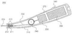
도 3은 본 발명의 바람직한 제1실시예에 따른 뼈채취장치 및 그 구동장치의 개략적인 전체사시도;Figure 3 is a schematic overall perspective view of a bone harvesting device and a drive device according to a first embodiment of the present invention;
도 4는 도 3의 뼈채취장치의 개략적인 분해사시도;Figure 4 is a schematic exploded perspective view of the bone extraction device of Figure 3;
도 5는 도 4의 앵커날의 개략적인 확대사시도;5 is a schematic enlarged perspective view of the anchor blade of FIG. 4;
도 6은 도 4의 "T"형 지지대들의 개략적인 확대사시도;FIG. 6 is a schematic enlarged perspective view of the “T” shaped supports of FIG. 4; FIG.
도 7은 도 4의 채취날의 개략적인 확대사시도;7 is a schematic enlarged perspective view of the blade of FIG. 4;
도 8은 도 4의 가동체를 다른 각도에서 나타낸 개략적인 사시도;8 is a schematic perspective view of the movable body of FIG. 4 from another angle;
도 9는 도 4의 A-A선을 따라 얻어진 뼈채취장치의 개략적인 조립단면도;Figure 9 is a schematic assembly cross-sectional view of the bone extraction device obtained along line A-A of Figure 4;
도 9a는 도 9의 점선으로 도시한 B 부위의 확대도;FIG. 9A is an enlarged view of a portion B shown by a dotted line in FIG. 9; FIG.
도 10은 도 9의 뼈채취장치의 작동상태를 나타내는 개략도;10 is a schematic view showing an operating state of the bone extraction device of FIG.
도 11은 도 3의 구동장치의 개략적인 조립단면도;FIG. 11 is a schematic cross-sectional view of the drive device of FIG. 3; FIG.
도 12는 도 11의 제2작동봉, 회전판 및 구동모터의 연결관계를 나타내는 개략적인 분해사시도;12 is a schematic exploded perspective view illustrating a connection relationship between a second operating rod, a rotating plate, and a driving motor of FIG. 11;
도 13은 본 발명의 바람직한 제2실시예에 따른 뼈채취장치 및 그 구동장치의 개략적인 전체사시도;Figure 13 is a schematic perspective view of a bone harvesting device and a drive device according to a second preferred embodiment of the present invention;
도 14는 도 13의 구동장치의 개략적인 분해단면도;14 is a schematic exploded cross-sectional view of the drive device of FIG. 13;
도 15는 도 14의 제2작동봉, 회전판 및 구동모터의 연결관계를 나타내는 개략적인 분해사시도;FIG. 15 is a schematic exploded perspective view illustrating a connection relationship between a second operating rod, a rotating plate, and a driving motor of FIG. 14;
도 16은 도 11의 회전판의 회전운동에 따른 제1,제2작동봉들의 움직임을 나타내는 예시도; 및16 is an exemplary view showing the movement of the first and second operating rods in accordance with the rotational movement of the rotating plate of FIG. And
도 17은 도 7의 채취날에 의해 뼈가 채취되는 상태를 순서대로 나타내는 개략적인 단면도들이다.FIG. 17 is a schematic cross-sectional view sequentially illustrating a state in which bone is collected by the sampling blade of FIG. 7.
이하, 첨부한 도면을 참조로 본 발명의 바람직한 실시예들에 따른 뼈채취장치 및 그 구동장치에 대하여 상세하게 설명한다.Hereinafter, with reference to the accompanying drawings will be described in detail with respect to the bone extraction device and its driving device according to preferred embodiments of the present invention.
제1실시예First embodiment
먼저, 도 3 내지 도 12를 참조로 본 발명의 바람직한 제1실시예에 따른 뼈채취장치 및 그 구동장치에 대하여 상세하게 설명한다. 도 3은 본 실시예에 따른 뼈채취장치 및 그 구동장치의 개략적인 전체사시도이다.First, with reference to Figures 3 to 12 will be described in detail with respect to the bone harvesting device and its driving device according to a first embodiment of the present invention. Figure 3 is a schematic overall perspective view of the bone harvesting device and its driving device according to the present embodiment.
도 3에 도시한 바와 같이, 본 실시예에 따른 뼈채취장치(100)와 그 구동장치(200)는 하나로 연결되어 사용되게 된다.As shown in FIG. 3, the
도 3의 뼈채취장치(100)의 구체적인 구성을 도 4에 도시하였다. 도 4는 도 3의 뼈채취장치의 개략적인 분해사시도이다.The detailed configuration of the
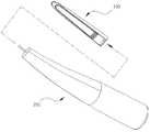
도 4에 도시한 바와 같이, 뼈채취장치(100)는 플라스틱과 같은 경량의 비금속 또는 금속재질로 만들어지는 고정연결체(110), 가동체(130) 및 덮개판(150)을 포함한다.As shown in FIG. 4, the
고정연결체(110)는 구동장치(200)에 삽입되게 연결되는 것으로, 가동체(130)를 여유 있게 수용하는 가동체수용공간(111)이 형성되고 끝단에는 구동장치(200)에 꽉 끼게 삽입되는 중공의 원통모양의 삽입연결부(112)가 일체로 돌출되게 형성된다.The fixed
또한 고정연결체(110)는 선단에 고정연결체(110)를 채취하고자 하는 뼈의 표면에 강하게 앵커링시키는 앵커날(113)이 고정되게 마련된다. 구체적으로 도시하지는 않았지만, 선단에는 앵커날(113)이 꽉 끼워지는 원호모양의 끼움홈이 형성되고, 이 끼움홈에 앵커날(113)이 고정되게 꽉 끼워진다.In addition, the fixed
앵커날(113)은 단단한 금속재질로 만들어지고 도 5에 확대하여 도시한 바와 같이 끼움홈에 꽉 끼워지는 원호모양의 끼움부(113a), 끼움부(113a)에 바깥쪽으로 경사지게 일체로 형성되는 경사부(113b) 및 경사부(113b) 끝단에 일체로 형성되는 다수의 뾰족돌기날(113c)들로 이루어진다. 도 9a에 참고로 도시한 바와 같이, 경사부(113b)는 가동체(130)가 후진할 때 고정연결체(110)가 앞으로 밀려나지 않도록 고정연결체(110)의 바닥수평면에 대해 110°~ 160°범위, 바람직하게는 120°~ 150°범위의 경사각(α1)을 갖는 것이 바람직하다.
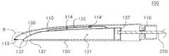
또한 고정연결체(110)는 안쪽면에 소정 간격을 두고 2개의 지지대고정홈(114)들이 형성되고, 이 지지대고정홈(114)들에는 "T"형 지지대(115, 115')들이 각각 고정되게 나사 결합된다.In addition, the fixed
"T"형 지지대(115, 115')들은 도 6에 확대하여 도시한 바와 같이 지지대고정홈(114)에 나사 결합되는 결합부(115a, 115a'), 결합부(115a, 115a')에 직교하게 연결되는 연결부(115b, 115b') 및 연결부(115b, 115b')에 길이방향으로 형성되는 안내레일삽입홈(115c, 115c')으로 구성된다."T" type supports 115 and 115 'are orthogonal to the
또한 고정연결체(110)는 후면에 거의 중앙에 구동장치(200)에 마련된 제1작동봉(220)이 관통되는 하나의 제1작동봉관통공(116)이 형성된다.In addition, the fixed
가동체(130)는 고정연결체(110) 속에 전후진운동이 가능하게 연결되는 것으로, 고정연결체(110) 속에 여유를 두고 수용되게 고정연결체(110) 보다 작게 형성되고 채취된 뼈가 수집되는 채취뼈수집공간(131)이 형성된다.
또한 가동체(130)는 선단에 뼈채취날(132)이 고정되게 마련된다. 구체적으로 도시하지는 않았지만, 선단에는 뼈채취날(132)이 꽉 끼워지는 원호모양의 끼움홈이 형성되고, 이 끼움홈에 뼈채취날(132)이 고정되게 꽉 끼워진다.In addition, the
뼈채취날(132)은 단단한 금속재질로 만들어지고 도 7에 확대하여 도시한 바와 같이 끼움홈에 꽉 끼워지는 원호모양의 끼움부(132a), 끼움부(132a)에 안쪽으로 경사지게 일체로 형성되는 경사부(132b) 및 경사부(132b) 끝단에 일체로 형성되는 거의 반달모양의 날부(132c)로 이루어진다. 도 9a에 참고로 도시한 바와 같이, 경사부(132b)는 가동체(130)의 바닥수평면에 대해 30°~ 110°범위, 바람직하게는 45°~ 90°범위의 경사각(α2)을 갖는 것이 바람직하다.
또한 가동체(130)는 도 8과 같이 상면에 가동체(130)의 전후진운동을 안내하는 안내레일(133)이 마련된다. 안내레일(133)은 반트랙모양을 갖고 양단이 가동체(130)의 상면에 형성된 한 쌍의 설치홈(134)에 고정되게 설치된다. 안내레일(133)은 길이방향으로 길게 안내홈(133a)이 형성되고 뒤쪽에 "T"형 지지대(114,114')들이 관통되는 관통공(133b)이 안내홈(133a)에 직교하거나 교차하게 형성된다. 안내레일(133)이 "T"형 지지대(114,114')들에 끼워지면 안내레일(133)의 안측이 "T"형 지지대(114,114')의 안내레일삽입홈(115c, 115c')에 끼워지게 된다.In addition, the
또한 가동체(130)는 채취뼈수집공간(131)을 한정하는 양측벽(135)에는 내측에 길이방향으로 길게 덮개판(150)이 삽입되는 덮개판삽입홈(136)이 각각 형성되고, 후면에는 거의 중앙에 구동장치(200)에 마련된 제1작동봉(220)이 관통되는 하나의 제2작동봉관통공(137)이 형성된다.In addition, the
덮개판(150)은 한 쪽으로 개방된 채취뼈수집공간(131)을 막도록 가동체(130)에 설치되는 것으로, 얇은 판모양을 갖는다. 덮개판(150)은 사용자에 의해 가동체(130)로부터 분리될 수 있게 뒤쪽에 폭방향으로 다수의 홈이 형성된 당김편(151)이 일체로 마련된다.The
상술한 뼈채취장치(100)가 조립된 상태를 도 9에 구체적으로 도시하였다. 도 9는 도 4의 A-A선을 따라 얻어진 뼈채취장치의 개략적인 조립단면도이다.9 illustrates a state in which the above-described
도 9에 도시한 바와 같이, 가동체(130) 상면에 마련된 안내레일(133)이 고정연결체(110)에 안쪽면에 마련된 "T"형 지지대(114,114')들에 의해 지지되게 가동체(130)가 고정연결체(110) 속에 연결되어 있다. 이때, 안내레일(133)이 우수한 탄성력을 갖기 때문에 가동체(130)가 고정연결체(110)에 대해 수직한 방향으로 탄성지지되게 된다.As shown in FIG. 9, the
덮개판(150)은 가동체(130)에 형성된 채취뼈수집공간(131)을 거의 막도록 가동체(130)에 형성된 덮개판삽입홈(도 4의 136)에 끼워져 있다. 이때, 덮개판(150)의 선단과 뼈채취날(132) 사이에는 개방된 공간(137)이 형성되어 뼈채취날(132)에 의해 절삭 또는 채취되는 뼈조각편(칩)들이 채취뼈수집공간(131)으로 쉽게 모여지게 된다.The
고정연결체(110)와 가동체(130)의 후면에는 제1작동봉관통공(116)과 제2작동봉관통공(137)을 관통하게 제1작동봉(220)이 설치된다. 이때, 제1작동봉(220)의 끝단부는 거의 십자형에 가까운 모양을 하고 있어, 이에 대응하게 형성된 제1작동봉관통공(116)과 제2작동봉관통공(137)에 맞게 끼워진 후 축방향으로 일정 각도 회전되면 제1작동봉(220)이 제1작동봉관통공(116)과 제2작동봉관통공(137)으로부터 빠지지 않게 된다.The
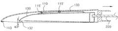
고정연결체(110)의 선단에 마련된 앵커날(113)은 가동체(130)의 선단에 마련된 뼈채취날(132) 보다 약간 위에 위치하고 있어, 앵커날(113)이 뼈의 표면에 닿을 때 뼈채취날(132)이 안내레일(133)의 탄성지지력에 의해 뼈의 표면에 강하게 밀리면서 닿게 된다. 이로써, 뼈를 절삭 또는 채취하는 동안 고정연결체(110)는 앵커날(113)에 의해 뼈의 표면에 고정되게 되고, 고정연결체(110)에 대한 가동체(130)의 운동에 의해 뼈채취날(132)이 뼈를 원활하게 절삭 또는 채취하게 된다.The
도 9a에 참고로 도시하였듯이, 앵커날(113)은 고정연결체(110)의 바닥수평면에 대해 110°~ 160°범위, 바람직하게는 120°~ 150°범위의 경사각(α1)을 갖는 것이 바람직하고, 뼈채취날(132)은 가동체(130)의 바닥수평면에 대해 30°~ 110°범위, 바람직하게는 45°~ 90°범위의 경사각(α2)을 갖는 것이 바람직하다. 앵커날(113)과 뼈채취날(132)은 이미 앞서 구체적으로 설명하였다.As shown in FIG. 9A, the
도 9의 뼈채취장치(100)의 작동상태를 도 10에 도시하였다. 도 10은 도 9의 뼈채취장치의 작동상태를 나타내는 개략도이다.The operating state of the
도 10에 도시한 바와 같이, 제1작동봉(220)이 화살표방향으로 움직이면, 가동체(130)가 고정연결체(110)에 대해 후진하면서 가동체(130)에 마련된 뼈채취날(132)이 뼈를 절삭 또는 채취하게 된다. 이때, 가동체(130)가 후진하면서 뼈를 절삭 또는 채취하는 힘에 의해 고정연결체(110)에 앞으로 밀리는 힘이 작용하게 되는 데, 고정연결체(110)에 마련된 앵커날(113)이 뼈의 표면에 강하게 앵커링되어 있어 이 힘에 저항하게 되고 고정연결체(110)는 앞으로 밀리지 않고 제자리에 고정되게 된다. 여기서, 가동체(130)의 후진 거리는 가동체(130)의 후면과 고정연결체(110)의 후면 사이에 형성된 거리와 거의 같게 된다.As illustrated in FIG. 10, when the
가동체(130)의 상면에 마련된 안내레일(133)이 직선구간과 곡선구간으로 이루어진 반트랙모양을 갖기 때문에 가동체(130)가 끝까지 후진하게 되면 "T"형 지지대(115,115')들이 곡선구간에 머물게 된다. 이때, 가동체(130)는 고정연결체(110)에 대해 도면에 도시하였듯이 α3각도 만큼 살짝 위로 들리게 된다. 이는 절삭 또는 채취되는 뼈의 표면이 직선구간과 곡선구간으로 형성되게 하여 뼈의 채취를 쉽게 하기 위함이다.Since the
다음, 도 11을 참조로 상술한 뼈채취장치(100)를 구동하는 구동장치에 대하여 설명한다. 도 11은 도 3의 구동장치의 개략적인 조립단면도이다.Next, with reference to Figure 11 will be described a drive device for driving the above-described
구동장치(200)는 본체(210), 제1작동봉(220), 제2작동봉(230), 회전판(240), 구동모터(250) 및 배터리(260)를 포함한다.The
본체(210)는 일자로 형성되거나 또는 약 10°~ 40°구부러지게 형성되어 사용자가 뼈를 채취하는 작업을 쉽게 도와준다.The
또한 본체(210)는 뼈채취장치(100)와 연결되는 면에 제1작동봉(220)이 직선운동 가능하게 관통되는 관통공(211)이 형성되고, 이 관통공(211)의 주변에 뼈채취장치(100)에 형성된 중공의 원통모양의 삽입연결부(도 4의 112)가 삽입되는 원통형의 삽입홈(212)가 형성된다.In addition, the
제1작동봉(220)은 뼈채취장치(100)의 가동체(130)에 운동력을 주기 위한 것으로, 십자모양의 일단부가 본체(210) 밖으로 돌출되게 마련되고, 본체(210) 속에 위치하는 타단부는 소정 거리를 두고 마련되는 2개의 베어링(213)에 의해 지지된다. 이 베어링(213)들은 제1작동봉(220)이 원할하게 직선왕복운동하는 것을 돕는다.The
제2작동봉(230)은 회전판(240)의 회전운동을 직선운동으로 변환하여 제1작동봉(220)에 운동력을 전달하기 위한 것으로, 일단부가 제1작동봉(220)의 타단부에 회전 가능하게 연결되고, 타단부는 회전판(240)에 회전 가능하게 연결된다.The
회전판(240)은 구동모터(250)로부터 구동력을 얻어 회전운동하는 것으로, 구동모터(250)는 배터리(260)로부터 전원을 얻어 구동되게 된다. 배터리(260)는 교체식 또는 충전식이 적용될 수 있으나, 충전식이 적용되는 것이 바람직하다. 또한 접촉식 또는 비접촉식 충전배터리가 적용될 수 있으나, 비접촉식 충전배터리가 적용되는 것이 바람직하다.The
본체(210)의 외면에는 구동모터(250)와 연결되어 구동모터(250)의 구동력으로부터 산정될 수 있는 뼈 채취양, 뼈 채취깊이, 뼈 채취상태 등을 사용자가 눈으로 확인할 수 있게 표시하는 표시장치(270)가 마련되고, 구동모터(250)의 작동 및 속도와 세기를 조절하는 조작버튼(280)도 마련된다.The outer surface of the
이해를 돕기 위해 상술한 제2작동봉, 회전판 및 구동모터의 연결관계를 도 12에 구체적으로 도시하였다. 도 12는 도 11의 제2작동봉, 회전판 및 구동모터의 연결관계를 나타내는 개략적인 분해사시도이다.12 illustrates the connection relationship between the second operating rod, the rotating plate, and the driving motor for the sake of understanding. FIG. 12 is a schematic exploded perspective view illustrating a connection relationship between a second operating rod, a rotating plate, and a driving motor of FIG. 11.
도 12에 도시한 바와 같이, 제2작동봉(230)의 타단부는 회전판(240)의 일면에 형성된 점선으로 도시한 삽입돌기(241)에 회전 가능하게 연결된다.As shown in FIG. 12, the other end of the
회전판(240)의 타면에는 환형의 종동기어(242)가 일체로 돌출되게 형성되고 중앙에는 회전판(240)을 축방향으로 회전 가능하게 지지하기 위한 회전축(243)이 형성된다.An annular driven
구동모터(250)의 구동축(251)에는 구동기어(252)가 고정되게 키결합되고, 이 구동기어(252)는 회전판(240)에 형성된 환형의 종동기어(242)에 기어 결합된다.The
구동모터(250)가 배터리로부터 전원을 받아 구동되면 구동축(251)이 구동되고 이와 함께 구동기어(252)도 구동되게 된다. 구동기어(252)가 구동되면 구동기어(252)와 기어 결합된 환형의 종동기어(242)도 따라서 구동되고 종동기어(242)와 일체로 형성된 회전판(240)이 회전축(243)을 중심으로 회전하게 된다. 이 회전판(240)의 회전운동에 의해 회전판(240)에 연결된 제2작동봉(230)의 운동하게 된다.When the driving
제2실시예Second embodiment
다음, 도 13과 도 14를 참조로 본 발명의 바람직한 제2실시예에 따른 뼈채취장치 및 그 구동장치에 대하여 상세하게 설명한다. 도 13은 본 발명의 바람직한 제2실시예에 따른 뼈채취장치 및 그 구동장치의 개략적인 전체사시도이고, 도 14는 도 13의 구동장치의 개략적인 분해단면도이다.Next, with reference to Figures 13 and 14 will be described in detail with respect to the bone extraction device and its driving device according to a second embodiment of the present invention. FIG. 13 is a schematic overall perspective view of a bone collecting device and a driving device thereof according to a second preferred embodiment of the present invention, and FIG. 14 is a schematic exploded cross-sectional view of the driving device of FIG. 13.
도 13 및 도 14에 도시한 바와 같이, 본 실시예는 뼈채취장치(100)가 앞선 제1실시예의 뼈채취장치(100)와 같은 구성을 갖는 반면, 구동장치(200')는 앞선 제1실시예의 구동장치(200)와 달리 두 부위, 즉 제1부위(200a)와 제2부위(200b)로 구성된다. 따라서, 설명의 불필요한 중복을 피하기 위하여 뼈채취장치(100)에 대한 설명은 생략하고 구동장치(200')에 대해서만 설명한다. 또한 제1실시예와 같은 구성요소들에 대해서는 같은 참조번호를 부여한다.As shown in Figures 13 and 14, the present embodiment has the same configuration as the
제1부위(200a)는 뼈채취장치(100)에 연결되는 것으로, 제1본체(210a), 제1작동봉(220), 제2작동봉(230), 회전판(240) 및 제1축봉(251a)을 포함한다.The
제1본체(210a)는 일자로 형성되거나, 또는 약 10°~ 40°구부러지게 형성되어 사용자가 뼈를 채취하는 작업을 쉽게 도와준다.The first body (210a) is formed in a date, or bent about 10 ° ~ 40 ° is formed to help the user to easily collect the bones.
또한 제1본체(210a)는 뼈채취장치(100)와 연결되는 면에 제1작동봉(220)이 직선운동 가능하게 관통되는 제1관통공(211)이 형성되고, 이 제1관통공(211)의 주변에 뼈채취장치(100)에 형성된 중공의 원통모양의 제1삽입연결부(도 4의 112)가 삽입되는 원통형의 제1삽입홈(212)이 형성된다.In addition, the
또한 제1본체(210a)는 제2부위(200b)와 연결되는 면에 제1축봉(215a)와 제2축봉(215b)이 삽입되는 제2관통공(214)이 형성되고, 이 제2관통공(214)의 주변에 제2부위(200b)에 형성된 중공의 원통모양의 제2삽입연결부(217)가 삽입되는 원통형의 제2삽입홈(215)이 형성된다.In addition, the
제1작동봉(220)은 뼈채취장치(100)의 가동체에 운동력을 주기 위한 것으로, 십자모양의 일단부가 제1본체(210a) 밖으로 돌출되게 마련되고, 제1본체(210a) 속에 위치하는 타단부는 소정 거리를 두고 마련되는 2개의 베어링(213)에 의해 지지된다. 이 베어링(213)들은 제1작동봉(220)이 원할하게 직선왕복운동하는 것을 돕는다.The
제2작동봉(230)은 회전판(240)의 회전운동을 직선운동으로 변환하여 제1작동봉(220)에 운동력을 전달하기 위한 것으로, 일단부가 제1작동봉(220)의 타단부에 회전 가능하게 연결되고, 타단부는 회전판(240)에 회전 가능하게 연결된다.The
회전판(240)은 제1축봉(251a)으로부터 구동력을 얻어 회전운동하게 되고, 제1축봉(251a)은 제2축봉(251b)과 연결된다.The
제2부위(200b)는 제1부위(200a)에 분리되게 연결되는 것으로, 제2본체(210b), 제2축봉(215b), 구동모터(250) 및 전선(290)을 포함한다.The
제2본체(210b)는 일자로 형성되고, 제1부위(200a) 또는 제1본체(210a)와 연결되는 면에 제2축봉(215b)이 직선운동 가능하게 관통되는 제3관통공(216)이 형성되고, 이 제3관통공(216)의 주변에 중공의 원통모양의 제2삽입연결부(217)가 형성된다.The
제2축봉(215b)은 구동모터(250)에 고정되게 연결되어 구동모터(250)로부터 구동력을 얻는다.The second shaft bar 215b is fixedly connected to the
구동모터(250)는 전선(290)과 연결되어 전선(290)을 통해 외부 전원을 공급받게 된다.The driving
제2본체(210b)의 외면에는 구동모터(250)와 연결되어 구동모터(250)의 구동력으로부터 산정될 수 있는 뼈 채취양, 뼈 채취깊이, 뼈 채취상태 등을 사용자가 눈으로 확인할 수 있게 표시하는 표시장치(270)가 마련되고, 구동모터(250)의 작동 및 속도와 세기를 조절하는 조작버튼(280)도 마련된다.On the outer surface of the second body (210b) is connected to the
이해를 돕기 위해 상술한 제2작동봉, 회전판 및 구동모터의 연결관계를 도 15에 구체적으로 도시하였다. 도 15는 도 14의 제2작동봉, 회전판 및 구동모터의 연결관계를 나타내는 개략적인 분해사시도이다.15 illustrates a connection relationship between the second operating rod, the rotating plate, and the driving motor for the sake of understanding. FIG. 15 is a schematic exploded perspective view illustrating a connection relationship between a second operating rod, a rotating plate, and a driving motor of FIG. 14.
도 15에 도시한 바와 같이, 제2작동봉(230)의 타단부는 회전판(240)의 일면에 형성된 점선으로 도시한 삽입돌기(241)에 회전 가능하게 연결된다.As shown in FIG. 15, the other end of the
회전판(240)의 타면에는 환형의 종동기어(242)가 일체로 돌출되게 형성되고 중앙에는 회전판(240)을 축방향으로 회전 가능하게 지지하기 위한 회전축(243)이 형성된다.An annular driven
제1축봉(215a)은 일단에 구동기어(252)가 고정되게 키결합되고 타단에 삽입홈(252a)이 형성된다. 이 구동기어(252)는 회전판(240)에 형성된 환형의 종동기어(242)에 기어 결합된다.The first shaft rod 215a is key-coupled to fix the
제2축봉(215b)은 일단에 삽입홈(252a)에 삽입되게 되는 십자모양의 삽입돌기(252b)가 형성되고 타단은 구동모터(250)에 고정되게 결합된다.The second shaft bar 215b has a
구동모터(250)가 전원을 받아 구동되면 제2축봉(215b)이 구동되고 이와 함께 제2축봉(215b)과 연결된 제1축봉(215a)과 구동기어(252)가 구동되게 된다. 구동기어(252)가 구동되면 구동기어(252)와 기어 결합된 환형의 종동기어(242)도 따라서 구동되고 종동기어(242)와 일체로 형성된 회전판(240)이 회전축(243)을 중심으로 회전하게 된다. 이 회전판(240)의 회전운동에 의해 회전판(240)에 연결된 제2작동봉(230)의 운동하게 된다.When the driving
다음, 제1실시예에 설명된 구성을 참조로 회전판(240)의 회전운동에 따른 제1작동봉(220)과 제2작동봉(230)의 움직임을 도 16에 예를 들어 도시하였다. 도 16은 도 10의 회전판의 회전운동에 따른 제1,제2작동봉들의 움직임을 나타내는 예시도들이다.Next, the movement of the
(a)는 회전판(240)이 운동하지 않는 상태를 나타낸다.(a) shows a state in which the
(a)상태에서 회전판(240)이 시계방향으로 90°회전되면, (b)와 같이 제1작동봉(220)의 화살표방향으로 직선운동하게 된다.In the state (a), when the
(b)상태에서 회전판(240)이 시계방향으로 90°더 회전되면, (c)와 같이 제1작동봉(220)의 화살표방향으로 더 직선운동하게 된다.In the state (b), when the
(c)상태에서 회전판(240)이 시계방향으로 90°더 회전되면, (d)와 같이 제1작동봉(220)의 화살표방향으로 반대로 직선운동하게 된다.When the
(c)상태에서 회전판(240)이 시계방향으로 90°더 회전되면, (a)와 같이 제1작동봉(220)의 원상태로 돌아오게 된다.When the
이와 같이 (a)~(d) 운동이 반복적으로 실행되면서 회전판(240)의 회전운동에 의해 제1작동봉(220)의 직선운동이 얻어지게 된다.As described above, (a) to (d) are repeatedly executed, the linear motion of the
본 발명의 뼈채취장치와 그 구동장치에 의해 뼈의 표면이 절삭 또는 채취되는 상태를 도 17에 순서대로 도시하였다. 도 17은 도 7의 채취날에 의해 뼈가 채취되는 상태를 순서대로 나타내는 개략적인 단면도들이다.17 shows a state in which the bone surface is cut or collected by the bone harvesting device and the driving device of the present invention in sequence. FIG. 17 is a schematic cross-sectional view sequentially illustrating a state in which bone is collected by the sampling blade of FIG. 7.
뼈채취장치를 뼈의 표면에 갖다 대면, (a)와 같이 뼈채취날(132)의 끝단이 뼈(1)의 표면에 꽉 밀착되게 된다.When the bone picking device is brought to the surface of the bone, as shown in (a), the end of the
다음, 구동장치의 구동력에 의해 뼈채취장치의 가동체가 움직이기 시작하면, (b)와 같이 가동체 끝단에 마련된 뼈채취날(132)이 뼈(1)의 표면을 절삭 또는 채취하기 시작한다. 이때, 절삭 또는 채취되기 시작하는 부위는 곡선형태를 띤다.Next, when the movable body of the bone picking device starts to move by the driving force of the driving device, the
다음, 뼈채취장치의 가동체가 계속 움직이면, (c)와 같이 가동체 끝단에 마련된 뼈채취날(132)이 뼈(1)의 표면을 절삭 또는 채취한다. 이때, 절삭 또는 채취되는 부위는 직선형태를 띤다.Next, when the movable body of the bone collecting device continues to move, the
다음, 뼈채취장치의 가동체가 완전히 끝까지 움직이면, (d)와 같이 가동체 끝단에 마련된 뼈채취날(132)이 뼈(1)의 표면을 절삭 또는 채취한다. 이때, 절삭 또는 채취되는 부위는 곡선형태를 띤다. 이는 고정연결체(110)의 안쪽면에 마련된 "T"형 지지대(115,115')가 가동체(130)의 상면에 마련된 안내레일(133)의 직선구간을 지나 곡선구간과 만나면서 가동체(130)가 위쪽으로 살짝 들려지기 때문이다.Next, when the movable body of the bone collecting device is completely moved to the end, as shown in (d), the
이상 본 발명의 바람직한 여러 실시예들을 참고로 뼈채취장치 및 그 구동장치에 대하여 설명하였지만, 본 발명의 사상을 벗어나지 않는 범위 안에서 다양한 변경, 변형 또는 수정이 가능함은 당업자에게 명백하다.While the bone harvesting device and its driving device have been described with reference to various preferred embodiments of the present invention, it will be apparent to those skilled in the art that various changes, modifications, or modifications can be made without departing from the spirit of the present invention.
Claims (34)
Translated fromKoreanApplications Claiming Priority (2)
| Application Number | Priority Date | Filing Date | Title |
|---|---|---|---|
| KR10-2010-0116105 | 2010-11-22 | ||
| KR1020100116105AKR101040979B1 (en) | 2010-09-07 | 2010-11-22 | Bone harvesting device and its driving device |
Publications (2)
| Publication Number | Publication Date |
|---|---|
| WO2012070822A2true WO2012070822A2 (en) | 2012-05-31 |
| WO2012070822A3 WO2012070822A3 (en) | 2012-08-30 |
Family
ID=46147147
Family Applications (1)
| Application Number | Title | Priority Date | Filing Date |
|---|---|---|---|
| PCT/KR2011/008892WO2012070822A2 (en) | 2010-11-22 | 2011-11-22 | Bone harvesting device and driving device thereof |
Country Status (1)
| Country | Link |
|---|---|
| WO (1) | WO2012070822A2 (en) |
Cited By (1)
| Publication number | Priority date | Publication date | Assignee | Title |
|---|---|---|---|---|
| WO2016188522A1 (en)* | 2015-05-28 | 2016-12-01 | Frank Zastrow | Surgical hand-held instrument, and a tool and a protection device |
Family Cites Families (5)
| Publication number | Priority date | Publication date | Assignee | Title |
|---|---|---|---|---|
| SE511575C2 (en)* | 1994-09-20 | 1999-10-25 | Bladhs Medical Ab | Method and apparatus for collecting bone tissue fragments |
| US5683406A (en)* | 1995-09-29 | 1997-11-04 | Maxilon Laboratories, Llc | Apparatus and method for harvesting bone |
| KR100347500B1 (en)* | 1998-06-03 | 2002-08-03 | 윤영석 | Apparatus for harvesting cartilage |
| JP2005152098A (en)* | 2003-11-21 | 2005-06-16 | Miwatec:Kk | Ultrasonic handpiece and ultrasonic horn used for this |
| ITRE20060030A1 (en)* | 2006-03-02 | 2007-09-03 | Cgm Spa | SURGICAL INSTRUMENT TO SCRATCH AND COLLECT BONE PARTICLES |
- 2011
- 2011-11-22WOPCT/KR2011/008892patent/WO2012070822A2/enactiveApplication Filing
Cited By (1)
| Publication number | Priority date | Publication date | Assignee | Title |
|---|---|---|---|---|
| WO2016188522A1 (en)* | 2015-05-28 | 2016-12-01 | Frank Zastrow | Surgical hand-held instrument, and a tool and a protection device |
Also Published As
| Publication number | Publication date |
|---|---|
| WO2012070822A3 (en) | 2012-08-30 |
Similar Documents
| Publication | Publication Date | Title |
|---|---|---|
| US8801738B2 (en) | Surgical disc removal tool | |
| JP7051903B2 (en) | Biopsy device with tip protection and mounting device | |
| EP1872709B1 (en) | Endoscope system, treatment instrument cartridge, and storage case | |
| US20100198106A1 (en) | Biopsy forceps for taking one or more samples | |
| WO2018194341A1 (en) | Control device and automatic water sampler including same | |
| DK1034740T3 (en) | Apparatus for blood collection for diagnostic purposes | |
| WO2012070822A2 (en) | Bone harvesting device and driving device thereof | |
| CN113208288B (en) | Hair removal wardrobe based on artificial intelligence | |
| JPS5929693Y2 (en) | Cell collection device for endoscope | |
| WO2016114484A1 (en) | Grafting scissors | |
| CN113974696B (en) | Pharyngeal swab specimen collector for severe pneumonia | |
| KR101040979B1 (en) | Bone harvesting device and its driving device | |
| EP0031228A1 (en) | Instrument for collecting tissue cells | |
| EP0990129B1 (en) | Device and method for taking samples, in particular asbestos samples, from walls and the like | |
| WO2020106008A1 (en) | Wearable bite block | |
| WO2016010184A1 (en) | Pet hair cutting device | |
| CN113017816B (en) | Novel knee joint nail puller | |
| WO2020159180A1 (en) | Cervical tissue sampling apparatus and sample tissue collecting device | |
| CN212438553U (en) | Visual laryngoscope | |
| WO1989002719A1 (en) | Improved laryngoscope | |
| CN114652257A (en) | An endoscopic mucosal flora sampling and scraping device | |
| CN216090602U (en) | Biopsy forceps suitable for cervical cancer screening | |
| CN213551980U (en) | Tissue puncture sampling gun | |
| CN212015656U (en) | Biopsy forceps tool for endoscopy | |
| CN221331275U (en) | Pig tonsil spring helping hand sample thief |
Legal Events
| Date | Code | Title | Description |
|---|---|---|---|
| 121 | Ep: the epo has been informed by wipo that ep was designated in this application | Ref document number:11843598 Country of ref document:EP Kind code of ref document:A2 | |
| NENP | Non-entry into the national phase | Ref country code:DE | |
| 122 | Ep: pct application non-entry in european phase | Ref document number:11843598 Country of ref document:EP Kind code of ref document:A2 |