WO2012060246A1 - Solar battery-equipped display device and electronic equipment - Google Patents
Solar battery-equipped display device and electronic equipmentDownload PDFInfo
- Publication number
- WO2012060246A1 WO2012060246A1PCT/JP2011/074498JP2011074498WWO2012060246A1WO 2012060246 A1WO2012060246 A1WO 2012060246A1JP 2011074498 WJP2011074498 WJP 2011074498WWO 2012060246 A1WO2012060246 A1WO 2012060246A1
- Authority
- WO
- WIPO (PCT)
- Prior art keywords
- solar cell
- display device
- liquid crystal
- crystal display
- panel
- Prior art date
Links
- 239000004973liquid crystal related substanceSubstances0.000claimsabstractdescription105
- 239000000758substrateSubstances0.000claimsabstractdescription104
- 238000010248power generationMethods0.000abstractdescription13
- 239000010408filmSubstances0.000description14
- 239000000463materialSubstances0.000description8
- 239000004065semiconductorSubstances0.000description8
- CIWBSHSKHKDKBQ-JLAZNSOCSA-NAscorbic acidChemical compoundOC[C@H](O)[C@H]1OC(=O)C(O)=C1OCIWBSHSKHKDKBQ-JLAZNSOCSA-N0.000description7
- 238000000034methodMethods0.000description7
- 230000003287optical effectEffects0.000description6
- 238000005229chemical vapour depositionMethods0.000description5
- 239000011347resinSubstances0.000description5
- 229920005989resinPolymers0.000description5
- XLOMVQKBTHCTTD-UHFFFAOYSA-NZinc monoxideChemical compound[Zn]=OXLOMVQKBTHCTTD-UHFFFAOYSA-N0.000description4
- 238000005286illuminationMethods0.000description4
- 229910052751metalInorganic materials0.000description4
- 239000002184metalSubstances0.000description4
- 239000010409thin filmSubstances0.000description4
- XUIMIQQOPSSXEZ-UHFFFAOYSA-NSiliconChemical compound[Si]XUIMIQQOPSSXEZ-UHFFFAOYSA-N0.000description3
- 230000005611electricityEffects0.000description3
- 239000011159matrix materialSubstances0.000description3
- 230000004048modificationEffects0.000description3
- 238000012986modificationMethods0.000description3
- 229910052710siliconInorganic materials0.000description3
- 239000010703siliconSubstances0.000description3
- 239000000853adhesiveSubstances0.000description2
- 230000001070adhesive effectEffects0.000description2
- 238000006243chemical reactionMethods0.000description2
- 238000004040coloringMethods0.000description2
- 230000007423decreaseEffects0.000description2
- 238000010586diagramMethods0.000description2
- 239000011521glassSubstances0.000description2
- AMGQUBHHOARCQH-UHFFFAOYSA-Nindium;oxotinChemical compound[In].[Sn]=OAMGQUBHHOARCQH-UHFFFAOYSA-N0.000description2
- 230000010287polarizationEffects0.000description2
- 230000001681protective effectEffects0.000description2
- XOLBLPGZBRYERU-UHFFFAOYSA-Ntin dioxideChemical compoundO=[Sn]=OXOLBLPGZBRYERU-UHFFFAOYSA-N0.000description2
- 229910001887tin oxideInorganic materials0.000description2
- 238000002834transmittanceMethods0.000description2
- 239000011787zinc oxideSubstances0.000description2
- ZCYVEMRRCGMTRW-UHFFFAOYSA-N7553-56-2Chemical compound[I]ZCYVEMRRCGMTRW-UHFFFAOYSA-N0.000description1
- WHXSMMKQMYFTQS-UHFFFAOYSA-NLithiumChemical compound[Li]WHXSMMKQMYFTQS-UHFFFAOYSA-N0.000description1
- NIXOWILDQLNWCW-UHFFFAOYSA-Nacrylic acid groupChemical groupC(C=C)(=O)ONIXOWILDQLNWCW-UHFFFAOYSA-N0.000description1
- 230000002411adverseEffects0.000description1
- 229910021417amorphous siliconInorganic materials0.000description1
- 230000015572biosynthetic processEffects0.000description1
- 239000003990capacitorSubstances0.000description1
- 230000000694effectsEffects0.000description1
- 229910052740iodineInorganic materials0.000description1
- 239000011630iodineSubstances0.000description1
- 238000010030laminatingMethods0.000description1
- 229910052744lithiumInorganic materials0.000description1
- 239000012466permeateSubstances0.000description1
- 239000000049pigmentSubstances0.000description1
- 229920003023plasticPolymers0.000description1
- 230000001902propagating effectEffects0.000description1
- 239000010453quartzSubstances0.000description1
- VYPSYNLAJGMNEJ-UHFFFAOYSA-Nsilicon dioxideInorganic materialsO=[Si]=OVYPSYNLAJGMNEJ-UHFFFAOYSA-N0.000description1
- 239000013589supplementSubstances0.000description1
- 229920001187thermosetting polymerPolymers0.000description1
Images


Classifications
- H—ELECTRICITY
- H10—SEMICONDUCTOR DEVICES; ELECTRIC SOLID-STATE DEVICES NOT OTHERWISE PROVIDED FOR
- H10F—INORGANIC SEMICONDUCTOR DEVICES SENSITIVE TO INFRARED RADIATION, LIGHT, ELECTROMAGNETIC RADIATION OF SHORTER WAVELENGTH OR CORPUSCULAR RADIATION
- H10F19/00—Integrated devices, or assemblies of multiple devices, comprising at least one photovoltaic cell covered by group H10F10/00, e.g. photovoltaic modules
- G—PHYSICS
- G02—OPTICS
- G02F—OPTICAL DEVICES OR ARRANGEMENTS FOR THE CONTROL OF LIGHT BY MODIFICATION OF THE OPTICAL PROPERTIES OF THE MEDIA OF THE ELEMENTS INVOLVED THEREIN; NON-LINEAR OPTICS; FREQUENCY-CHANGING OF LIGHT; OPTICAL LOGIC ELEMENTS; OPTICAL ANALOGUE/DIGITAL CONVERTERS
- G02F1/00—Devices or arrangements for the control of the intensity, colour, phase, polarisation or direction of light arriving from an independent light source, e.g. switching, gating or modulating; Non-linear optics
- G02F1/01—Devices or arrangements for the control of the intensity, colour, phase, polarisation or direction of light arriving from an independent light source, e.g. switching, gating or modulating; Non-linear optics for the control of the intensity, phase, polarisation or colour
- G02F1/13—Devices or arrangements for the control of the intensity, colour, phase, polarisation or direction of light arriving from an independent light source, e.g. switching, gating or modulating; Non-linear optics for the control of the intensity, phase, polarisation or colour based on liquid crystals, e.g. single liquid crystal display cells
- G02F1/133—Constructional arrangements; Operation of liquid crystal cells; Circuit arrangements
- G02F1/13306—Circuit arrangements or driving methods for the control of single liquid crystal cells
- H—ELECTRICITY
- H02—GENERATION; CONVERSION OR DISTRIBUTION OF ELECTRIC POWER
- H02S—GENERATION OF ELECTRIC POWER BY CONVERSION OF INFRARED RADIATION, VISIBLE LIGHT OR ULTRAVIOLET LIGHT, e.g. USING PHOTOVOLTAIC [PV] MODULES
- H02S40/00—Components or accessories in combination with PV modules, not provided for in groups H02S10/00 - H02S30/00
- H02S40/30—Electrical components
- H02S40/38—Energy storage means, e.g. batteries, structurally associated with PV modules
- G—PHYSICS
- G02—OPTICS
- G02F—OPTICAL DEVICES OR ARRANGEMENTS FOR THE CONTROL OF LIGHT BY MODIFICATION OF THE OPTICAL PROPERTIES OF THE MEDIA OF THE ELEMENTS INVOLVED THEREIN; NON-LINEAR OPTICS; FREQUENCY-CHANGING OF LIGHT; OPTICAL LOGIC ELEMENTS; OPTICAL ANALOGUE/DIGITAL CONVERTERS
- G02F1/00—Devices or arrangements for the control of the intensity, colour, phase, polarisation or direction of light arriving from an independent light source, e.g. switching, gating or modulating; Non-linear optics
- G02F1/01—Devices or arrangements for the control of the intensity, colour, phase, polarisation or direction of light arriving from an independent light source, e.g. switching, gating or modulating; Non-linear optics for the control of the intensity, phase, polarisation or colour
- G02F1/13—Devices or arrangements for the control of the intensity, colour, phase, polarisation or direction of light arriving from an independent light source, e.g. switching, gating or modulating; Non-linear optics for the control of the intensity, phase, polarisation or colour based on liquid crystals, e.g. single liquid crystal display cells
- G02F1/133—Constructional arrangements; Operation of liquid crystal cells; Circuit arrangements
- G02F1/13306—Circuit arrangements or driving methods for the control of single liquid crystal cells
- G02F1/13324—Circuits comprising solar cells
- Y—GENERAL TAGGING OF NEW TECHNOLOGICAL DEVELOPMENTS; GENERAL TAGGING OF CROSS-SECTIONAL TECHNOLOGIES SPANNING OVER SEVERAL SECTIONS OF THE IPC; TECHNICAL SUBJECTS COVERED BY FORMER USPC CROSS-REFERENCE ART COLLECTIONS [XRACs] AND DIGESTS
- Y02—TECHNOLOGIES OR APPLICATIONS FOR MITIGATION OR ADAPTATION AGAINST CLIMATE CHANGE
- Y02E—REDUCTION OF GREENHOUSE GAS [GHG] EMISSIONS, RELATED TO ENERGY GENERATION, TRANSMISSION OR DISTRIBUTION
- Y02E10/00—Energy generation through renewable energy sources
- Y02E10/50—Photovoltaic [PV] energy
- Y—GENERAL TAGGING OF NEW TECHNOLOGICAL DEVELOPMENTS; GENERAL TAGGING OF CROSS-SECTIONAL TECHNOLOGIES SPANNING OVER SEVERAL SECTIONS OF THE IPC; TECHNICAL SUBJECTS COVERED BY FORMER USPC CROSS-REFERENCE ART COLLECTIONS [XRACs] AND DIGESTS
- Y02—TECHNOLOGIES OR APPLICATIONS FOR MITIGATION OR ADAPTATION AGAINST CLIMATE CHANGE
- Y02E—REDUCTION OF GREENHOUSE GAS [GHG] EMISSIONS, RELATED TO ENERGY GENERATION, TRANSMISSION OR DISTRIBUTION
- Y02E70/00—Other energy conversion or management systems reducing GHG emissions
- Y02E70/30—Systems combining energy storage with energy generation of non-fossil origin
Definitions
- the present inventionrelates to a display device and an electronic device provided with a solar cell.
- Mobile electronic devicessuch as mobile phones are now gaining importance as daily necessities. These portable electronic devices generally operate using a secondary battery such as a lithium battery as a power source.
- the secondary batteryis charged by supplying power from an external power source such as an outlet.
- an external power sourcesuch as an outlet.
- a device that charges a secondary battery with power generated by a dry cell or a solar cellmay be used.
- These charging deviceshave an advantage that it is not necessary to secure an external power source.
- itis necessary to carry it with the portable electronic device, and it is necessary to connect to the portable electronic device for charging. From the above, it is desired to mount a solar cell on a portable electronic device.
- Patent Document 1discloses a liquid crystal display device including a solar cell.
- FIG. 10is a cross-sectional view showing the configuration of the liquid crystal display device disclosed in Patent Document 1.
- a solar cell 207 and a liquid crystal panel 206are respectively disposed in two windows 204 and 205 opened in the housing 203, and an illumination light source 208 is disposed in the housing 203.
- a light guide plate 209that irradiates the light receiving surface of the solar cell 207 with the irradiation light of the illumination light source 208 is provided.
- the present inventionhas been made in view of the above problems, and an object of the present invention is to provide a display device and an electronic apparatus including a solar cell that can secure a power generation area of the solar cell while suppressing an increase in the total occupied volume. Is to provide.
- a display device of the present inventionincludes a display panel having a display area for displaying an image, and a solar cell formed in the display area and transmitting light for displaying the image. It is characterized by providing.
- the solar cellsince the solar cell is provided in the display area of the display panel, power can be generated by the solar cell along with the display of an image in the display area. Thereby, the electric power generation area of a solar cell can be ensured, suppressing the increase in the occupied volume of the whole display apparatus.
- the display device of the present inventionincludes a display panel having a display area for displaying an image, and a solar cell formed in the display area and transmitting light for displaying the image.
- An electronic apparatusincludes the display device.
- a display device and an electronic device including a solar cellthat can secure a power generation area of the solar cell while suppressing an increase in the entire occupied volume.
- FIG. 6is a block diagram showing a configuration of a liquid crystal display device of the present invention according to a modification of Example 1.
- FIG. 8is a perspective view showing a configuration of a main part of a conventional liquid crystal display device.
- the liquid crystal panel 120 of the liquid crystal display device 100has a configuration in which a TFT substrate 102 and a counter substrate 101 are arranged to face each other, and a liquid crystal layer 103 (see FIG. 8) is enclosed therebetween. ing.
- a terminal(not shown) patterned with a metal thin film is formed on the TFT substrate 102, and the terminal and an external circuit are electrically connected via an FPC (Flexible Printed Circuit) 104 that is crimped to the terminal region. Is done.
- FPCFlexible Printed Circuit
- an area surrounded by a broken lineis a display area P, and a plurality of pixels are arranged in a matrix in the display area P.
- FIG. 9is a cross-sectional view showing a laminated structure of the liquid crystal panel 120 in the conventional liquid crystal display device.
- the liquid crystal display device 100includes a liquid crystal panel 120 and a backlight 130.
- a color filter 111, a counter electrode (not shown), and an alignment film (not shown)are formed in this order on one surface of the counter substrate 101 facing the TFT substrate 102, and a surface polarizing plate 110 is formed on the other surface. ing.
- the color filter 111includes a colored layer or a black matrix (BM) layer that transmits red (R), green (G), and blue (B) light corresponding to each pixel.
- BMblack matrix
- This colored layeris a “coloring material” or “colored film” applied to the counter substrate 101 with a fine pattern, and a pigment-based or dye-based one is used.
- the BM layeris composed of a member that blocks light, prevents light leakage at the time of black display and color mixing between adjacent coloring materials, and prevents generation of photocurrent due to light irradiation to the TFT.
- the surface polarizing plate 110has a polarizing effect caused by bonding a protective film to the entire surface of the polarizing film.
- a TFT layer 112 and an alignment filmare formed in this order on one surface of the TFT substrate 102 facing the counter substrate 101, and a back polarizing plate 113 is formed on the other surface.
- the TFT layer 112is formed corresponding to each pixel, and includes a TFT that performs a switching operation, a pixel electrode formed corresponding to this TFT, a gate wiring and a source wiring that supply a gate signal and a source signal to the TFT, respectively. Is formed.
- the back polarizing plate 113has a polarizing film in which a protective film is bonded to the entire back surface of the polarizing film.
- the back polarizing plate 113allows only light (polarized light) having an amplitude component in a specific direction out of light incident from the backlight 130 to pass, and the rest is absorbed by a polarizing element such as iodine molecules.
- the light that has passed through the back polarizing plate 113enters the liquid crystal layer 103 as linearly polarized light.
- the incident light of linearly polarized lightchanges its polarization state according to the refractive index anisotropy (birefringence) of the liquid crystal while propagating through the liquid crystal layer 103 in the thickness direction.
- the emitted light that has passed through the liquid crystal layer 103only light having a polarization component in a specific direction restricted by the front polarizing plate 110 is emitted as display light.
- a backlight 130is formed on the surface of the back polarizing plate 113 opposite to the surface facing the TFT substrate 102.
- the backlight 130includes a light guide plate 115 and a light source (not shown) provided at an end of the light guide plate 115.
- the light guide plate 115diffuses and emits light incident from a light source such as a cold cathode tube or an LED (Light Emitting Diode) so as to be uniform in the plane.
- a light sourcesuch as a cold cathode tube or an LED (Light Emitting Diode) so as to be uniform in the plane.
- an optical sheet 114is formed on one surface of the light guide plate 115 facing the TFT substrate 102, and a reflective sheet 116 is formed on the other surface.
- the optical sheet 114is composed of, for example, a diffusing plate or a prism sheet, and diffuses the light incident from the light guide plate 115 by the diffusing plate so as to be uniform in the plane and emits the light in the front direction by the prism sheet.
- the lightis condensed and emitted.
- the reflection sheet 116is composed of a member that reflects light, and improves the light utilization rate by reusing the light leaking from the light guide plate 115.
- a backlight frame 117 made of metalis formed on the surface of the reflection sheet 116 opposite to the surface facing the light guide plate 115.
- Example 1The present embodiment will be described below with reference to FIGS. (Overall configuration of liquid crystal display device) First, the overall configuration of the liquid crystal display device according to the present embodiment will be described with reference to FIGS.
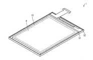
- FIG. 1is a perspective view showing a configuration of a main part of the liquid crystal display device according to the present embodiment.
- the liquid crystal panel 30 of the liquid crystal display device 1has a configuration in which a TFT substrate 32 and a counter substrate 31 are arranged to face each other, and a liquid crystal layer 37 (see FIG. 2) is enclosed therebetween. ing.
- a region surrounded by a broken lineis a display region P, and a plurality of pixels are arranged in a matrix in the display region P.
- the solar cell panel 10is formed so as to cover the entire display area P.
- FIG. 2is a cross-sectional view showing a configuration of a main part of the liquid crystal display device according to the present embodiment.
- the liquid crystal display device 1 according to the present embodimentis different from the conventional liquid crystal display device 100 in that a solar cell panel 10 is stacked on a liquid crystal panel 30.
- the liquid crystal panel 30has a configuration in which a TFT substrate 32 and a counter substrate 31 are arranged to face each other, and a liquid crystal layer 37 is enclosed therebetween.
- a color filter 34, a counter electrode (not shown), and an alignment film (not shown)are formed in this order on one surface of the counter substrate 31 facing the TFT substrate 32, and a surface polarizing plate (polarized light) is formed on the other surface. Plate) 33 is formed.
- a TFT layer 35 and an alignment filmare formed in this order on one surface of the TFT substrate 32 facing the counter substrate 31, and a back polarizing plate 36 is formed on the other surface.
- the TFT layer 35is formed corresponding to each pixel and includes a TFT that performs a switching operation, a pixel electrode formed corresponding to the TFT, a gate wiring and a source wiring that supply a gate signal and a source signal to the TFT, respectively. Is formed.
- the solar cell panel 10On the front polarizing plate 33, the solar cell panel 10 is formed.
- This solar cell panel 10is a see-through solar cell panel, and the configuration will be described in detail later.
- a backlight 50is formed on the surface opposite to the surface facing the TFT substrate 32 of the back polarizing plate (polarizing plate) 36.
- the backlight 50includes a light guide plate 51 and a light source (not shown) provided at an end of the light guide plate 51.
- the light guide plate 51diffuses and emits light incident from a light source such as a cold cathode tube or an LED (Light Emitting Diode) so as to be uniform in the plane.
- a light sourcesuch as a cold cathode tube or an LED (Light Emitting Diode) so as to be uniform in the plane.
- An optical sheet 52is formed on one surface of the light guide plate 51 facing the TFT substrate 32, and a reflective sheet 53 is formed on the other surface.
- the optical sheet 52is composed of, for example, a diffusing plate or a prism sheet, and diffuses the light incident from the light guide plate 51 by the diffusing plate so as to be uniform in the plane and emits the light in the front direction by the prism sheet. The light is condensed and emitted.
- the reflection sheet 53is composed of a member that reflects light, and improves the light utilization rate by reusing light leaked from the light guide plate 51.
- a backlight frame 54 made of metalis formed on the surface of the reflection sheet 53 opposite to the surface facing the light guide plate 51.
- the solar cell panel 10As described above, the solar cell panel 10 according to this embodiment is a see-through solar cell panel.
- a solar cell panel in which specific light passes through the solar cell panelis referred to as a see-through solar cell panel.
- FIG. 3is a plan view showing the configuration of the solar cell panel 10 according to the present embodiment.
- the solar cell panel 10is configured to include a plurality of solar cells C electrically connected in series or in parallel between two insulating translucent substrates 11.
- the insulating translucent substrate 11include a substrate using glass, quartz, transparent plastic, or the like as a material.
- glasshaving a thickness of 4 mm to 0.1 mm can be used.
- Each solar cell Cis configured by laminating a front electrode, a photoelectric conversion layer in which a semiconductor film is laminated, and a back electrode in this order.
- the surface electrodeis not particularly limited as long as it has conductivity and translucency, and specific examples include a transparent conductive film made of a material such as tin oxide, zinc oxide, or ITO (Indium Tin Oxide). .
- the photoelectric conversion layeris usually formed by a pn junction having a p-type semiconductor layer and an n-type semiconductor layer, or by a pin junction having a p-type semiconductor layer, an i-type semiconductor layer, and an n-type semiconductor layer. However, it is not limited to this.
- the solar cell CWhen formed by a pn junction having a p-type semiconductor layer and an n-type semiconductor layer, the solar cell C has a configuration in which a transparent electrode, an n-type silicon layer, a p-type silicon layer, and a transparent electrode are stacked in this order.
- the material for the silicon layerit is preferable to use amorphous silicon.
- a transparent conductive film made of a material such as tin oxide, zinc oxide or ITO (Indium Tin Oxide)can be used for the back electrode. Moreover, even if it is a metal, a very thin electrode film can be used so that it may have a light transmittance.
- the solar cell panel 10 as described aboveis easily fixed on the liquid crystal panel 30 using a double-sided tape, a resin adhesive, or the like, outside the display area P of the liquid crystal panel 30 (so-called “frame” portion). Can do.
- the solar cell panel 10can be fixed to the liquid crystal panel 30 using a transparent double-sided tape, a resin adhesive, or the like.
- the tape materialinclude general rubber and acrylic tapes
- examples of the resin materialinclude a UV curable resin and a thermosetting resin, but are not limited thereto.
- the liquid crystal display device 1is provided with a solar cell panel 10 that generates power using external light (illumination light such as sunlight and fluorescent lamps), and therefore it is necessary to supply power from an external power source. Or the frequency of supplying power from an external power source can be reduced.
- external lightillumination light such as sunlight and fluorescent lamps
- the solar cell panel 10is formed in the display area P so as to cover the display area P, it is possible to secure a power generation area while suppressing an increase in the occupied volume of the entire liquid crystal display device 1. Moreover, since the solar cell panel 10 is formed on the entire display area P, it is possible to prevent a difference in visibility and the like from occurring.
- the surface polarizing plate 33is disposed on the opposite surface of the counter substrate 31 to the surface facing the TFT substrate 32, and the solar cell panel 10 is laminated on the surface polarizing plate 33. It is arranged. Thereby, since external light does not permeate
- the solar cell panel 10has a high transmittance with respect to visible light, and has a characteristic of converting light other than visible light into electricity with high efficiency.
- the power generation capacity of the solar cell panel 10is not limited to using external light (illumination light such as sunlight and fluorescent lamps), for example, light from the backlight 50 of the device itself, without adversely affecting the display. Can be maximized.
- external lightillumination light such as sunlight and fluorescent lamps
- the solar cell panel 10may be disposed on the opposite surface of the counter substrate 31 to the surface facing the TFT substrate 32, and the front polarizing plate 33 may be stacked on the solar cell panel 10.
- the front polarizing plate 33may be stacked on the solar cell panel 10.
- one of the two insulating translucent substrates 11 constituting the solar cell panel 10can also be used as the counter substrate 31.
- the liquid crystal display device 1can be thinned to prevent a decrease in luminance.
- the liquid crystal display device 1may include a power storage element.
- FIG. 11is a block diagram illustrating a configuration of a liquid crystal display device 1 a which is a modification of the liquid crystal display device 1.
- a solar battery panel 10includes a solar battery panel 10, a liquid crystal panel 30, a backlight 50, a power storage element 60, and a power supply circuit 65.
- the electricity storage element 60is composed of a capacitor, for example, and is supplied with electric power from the solar cell panel 10 and stores the supplied electric power. Then, the stored electric power is output to the power supply circuit 65.
- the power supply circuit 65is supplied with electric power from the battery 70 arranged outside the liquid crystal display device 1a, a commercial power supply, or the like, and is also supplied with electric power from the storage element 60. Then, the power supply circuit 65 supplies power for driving each of the solar battery panels 10, the liquid crystal panel 30, and the backlight 50 to the respective drive circuits. Thereby, electric power is supplied to each of the solar cell panel 10, the liquid crystal panel 30, and the backlight 50, and the liquid crystal display device 1a is driven.
- the power supply circuit 65does not necessarily need to be supplied with power from both the battery 70 and the storage element 60.
- the power supply circuit 65is supplied from the battery 70 when the battery 70 has a large amount of electricity stored, and the power is supplied only from the battery 70.
- the power supply sourcemay be switched so that power is supplied.
- the liquid crystal display device 1 aincludes the power storage element 60 that supplies power for driving the liquid crystal display device 1 a and is charged by the solar cell panel 10.
- the solar cell panel 10which produces electric power using sunlight, for example, it can store with the electrical storage element 60 and can supply electric power to the liquid crystal display device 1a also at night.
- the solar battery panel 10 having a plurality of solar battery cells Cis fixed to the liquid crystal panel 30 as a solar battery between the two insulating translucent substrates 11, but is not limited thereto. There is nothing.
- the solar battery cell Ccan be directly formed on the surface polarizing plate 33 by using a CVD (Chemical Vapor Deposition) method, a printing method, or the like.
- CVDChemical Vapor Deposition
- the liquid crystal display device 1can be thinned. While being realizable, the bad influence on a display, such as the fall of visibility by providing the solar cell panel 10, can further be reduced.
- the solar battery panel 10 having a plurality of solar cells Cis formed so as to cover the display region P, but the present invention is not limited to this.
- the solar battery panel 10 including one solar battery cell Cmay be formed so as to cover the display region P.
- the liquid crystal display device 1can be used in an electronic device such as a mobile phone.
- the power generation area of the solar cell panel 10can be secured while suppressing an increase in the occupied volume of the entire electronic device in which the liquid crystal display device 1 is mounted.
- Example 2Hereinafter, Example 2 is demonstrated based on FIG. FIG. 4 is a cross-sectional view showing the configuration of the liquid crystal display device according to the present embodiment.
- the arrangement position of the solar cell panel 10is different from that in the first embodiment.
- the solar cell panel 10is formed on the front polarizing plate 33, but in this example, the solar cell panel 10 faces the TFT substrate 32 of the counter substrate 31.
- the color filter 34is formed on the surface (one surface) to be formed.
- the solar cell panel 10is disposed between the TFT substrate 32 and the counter substrate 31.
- a solar cell panel having a plurality of solar cells C between two insulating translucent substrates 11 as shown in FIG. 3can be used.
- one insulating translucent substrate 11can also serve as the counter substrate 31.
- one of the two insulating translucent substrates 11 constituting the solar cell panel 10may be used as the counter substrate 31. Thereby, the liquid crystal display device 1 can be made into a thin film, and a reduction in luminance can be prevented.
- the solar battery cell Ccan be directly formed on one surface of the counter substrate 31 by using a CVD method, a printing method, or the like. Thereby, thickness reduction of the liquid crystal display device 1 is realizable.
- FIG. 5is a cross-sectional view showing the configuration of the liquid crystal display device according to this embodiment.
- the arrangement position of the solar cell panel 10is different from that in the first embodiment.
- the solar cell panel 10is formed on the front polarizing plate 33, but in this example, the solar cell panel 10 faces the counter substrate 31 of the TFT substrate 32.
- the TFT layer 35is formed on the surface (one surface).
- the solar cell panel 10is disposed between the TFT substrate 32 and the counter substrate 31.
- the solar cell panel 10a solar cell panel having a plurality of solar cells C between two insulating translucent substrates 11 as shown in FIG. 3 can be used.
- the single insulating translucent substrate 11can also serve as the TFT substrate 32.
- one of the two insulating translucent substrates 11 constituting the solar cell panel 10may be the TFT substrate 32.
- the liquid crystal display device 1can be made into a thin film, and a reduction in luminance can be prevented.
- the solar battery cell Ccan be directly formed on one surface of the TFT substrate 32 by using a CVD method, a printing method, or the like. Thereby, thickness reduction of the liquid crystal display device 1 is realizable.
- Example 4Hereinafter, Example 4 is demonstrated based on FIG.
- FIG. 6is a cross-sectional view showing the configuration of the liquid crystal display device according to this example.
- the arrangement position of the solar cell panel 10is different from that in the first embodiment.
- Example 1the solar cell panel 10 is formed on the front polarizing plate 33, but in this example, the solar cell panel 10 is formed on the other surface of the TFT substrate 32. A back polarizing plate 36 is formed thereon.
- a solar cell panel having a plurality of solar cells C between two insulating translucent substrates 11 as shown in FIG. 3can be used.
- the single insulating translucent substrate 11can also serve as the TFT substrate 32.
- the solar cell Ccan be directly formed on the other surface of the TFT substrate 32 by using a CVD method, a printing method, or the like. Thereby, thickness reduction of the liquid crystal display device 1 is realizable.
- the solar cell panel 10is disposed on the other surface of the TFT substrate 32 opposite to the one surface facing the counter substrate 31.
- the liquid crystal display device 1includes a back polarizing plate 36 formed on the solar cell panel 10.
- the solar cell panel 10is located close to the backlight 50, the light in the backlight 50 can be used effectively. That is, it is possible to efficiently generate power using the light from the backlight 50.
- one of the two insulating translucent substrates 11 constituting the solar cell panel 10may be the TFT substrate 32.
- the liquid crystal display device 1can be made into a thin film, and a reduction in luminance can be prevented.
- the solar cell panel 10can be disposed on the optical sheet 52. According to the said structure, since the solar cell panel 10 is located near the backlight 50, it can utilize the light in the backlight 50 effectively.
- FIG. 7is a cross-sectional view showing the configuration of the liquid crystal display device according to this example.
- the solar cell panel 10is formed in one place, but in this embodiment, the solar cell panel 10 is formed in two places.
- Example 1the solar cell panel 10 is formed on the front polarizing plate 33, but in this example, the solar cell panel 10 is on the front polarizing plate 33 and the TFT substrate 32. Each is formed. Thereby, the power generation capability of the solar cell can be improved. Since the method for forming the solar cell panel 10 on the front polarizing plate 33 and the TFT substrate 32 has been described in the first and third embodiments, the description thereof is omitted here.
- one of the two insulating translucent substrates 11 constituting the solar cell panel 10 disposed on the TFT substrate 32may be used also as the TFT substrate 32.
- the liquid crystal display device 1is not limited to the configuration described based on the first to fifth embodiments.
- the solar cell panel 10can be provided in the vicinity of the touch panel.
- the present inventionis applied to a liquid crystal display device as an example.
- the present inventionis not limited to this, and various display devices such as an organic EL display device can be used. Can be applied.
- an electronic devicesuch as a mobile phone equipped with the display device of the present invention
- the solar cellWhen the solar cell generates power and supplies power to the electronic device, it is not necessary to supply power from an external power source.
- the display device of the present inventionincludes a display panel having a display area for displaying an image, and a solar cell that is formed in the display area and transmits light for displaying the image. It is characterized by.
- the solar cellsince the solar cell is provided in the display area of the display panel, power can be generated by the solar cell along with the display of an image in the display area. Thereby, the electric power generation area of a solar cell can be ensured, suppressing the increase in the occupied volume of the whole display apparatus.
- the display device of the present inventionpreferably further includes another solar cell that is formed so as to overlap with the solar cell and transmits light for displaying the image.
- the power generation capacity of the solar cellcan be improved.
- the solar cellis preferably formed so as to cover the entire display region.
- the solar cellis formed in the entire display region, it is possible to prevent a difference in visibility due to the presence or absence of the solar cell. Moreover, according to the said structure, compared with the case where a solar cell is formed in a part of display area, the electric power generation area of a solar cell can be ensured more widely.
- the display device of the present inventionincludes a power storage element that supplies power for driving the display panel and is charged by the solar cell.
- a solar battery that generates power using sunlightcan supply power to the display device at night by storing power in the storage element.
- the display panelis specifically formed corresponding to each pixel, a TFT substrate on which a switching operation TFT is formed, a counter substrate disposed to face the TFT substrate, It is preferable that a liquid crystal layer sealed between the TFT substrate and the counter substrate is provided. Thereby, the display panel can be obtained.
- the solar cellincludes two insulating substrates disposed to face each other and a solar cell disposed between the insulating substrates, and one of the two insulating substrates is the It may be a TFT substrate or the counter substrate.
- the display devicecan be made thin, and a reduction in luminance of the display panel can be prevented.
- a polarizing plateis disposed on a side surface of the counter substrate opposite to the surface facing the TFT substrate, and the solar cell is stacked on the polarizing plate.
- the solar cellmay be disposed between the TFT substrate and the counter substrate.
- the substrate constituting the solar cellcan also be used as the TFT substrate or the counter substrate. Therefore, the brightness
- the solar cellis disposed on the other surface of the TFT substrate opposite to the one surface facing the counter substrate, and a polarizing plate formed on the solar cell is provided. You may have.
- the electronic apparatus of the present inventionincludes the display device.
- the solar cellgenerates power and supplies power to the electronic device, it is not necessary to supply power from an external power source.
- the present inventioncan be suitably used for a display device and an electronic device provided with a solar cell.
Landscapes
- Physics & Mathematics (AREA)
- Nonlinear Science (AREA)
- Mathematical Physics (AREA)
- Chemical & Material Sciences (AREA)
- Crystallography & Structural Chemistry (AREA)
- General Physics & Mathematics (AREA)
- Optics & Photonics (AREA)
- Devices For Indicating Variable Information By Combining Individual Elements (AREA)
- Photovoltaic Devices (AREA)
- Liquid Crystal (AREA)
Abstract
Description
Translated fromJapanese本発明は、太陽電池を備えた表示装置及び電子機器に関する。The present invention relates to a display device and an electronic device provided with a solar cell.
携帯電話等の携帯電子機器は、現在では日常生活の必需品として重要度を増している。これらの携帯電子機器は、一般的にリチウム電池等の二次電池を電源として動作している。この二次電池の充電は、コンセント等の外部電源から電力を供給することによって行われる。携帯電子機器は、利用中または携帯中に充電量が減少するが、充電を行うための電源確保が困難な場合が多い。Mobile electronic devices such as mobile phones are now gaining importance as daily necessities. These portable electronic devices generally operate using a secondary battery such as a lithium battery as a power source. The secondary battery is charged by supplying power from an external power source such as an outlet. Although the amount of charge of a portable electronic device decreases during use or while being carried, it is often difficult to secure a power source for charging.
充電量を補うために、乾電池あるいは太陽電池により発電した電力により、二次電池を充電する機器が利用されることがある。これらの充電機器は、外部電源を確保する必要がない利点がある。しかしながら、その反面、携帯電子機器と共に携帯する必要があり、また、充電のために携帯電子機器と接続する必要があるため、移動中等には取り扱いに不便である。以上のことから、太陽電池を携帯電子機器に搭載することが望まれる。In order to supplement the amount of charge, a device that charges a secondary battery with power generated by a dry cell or a solar cell may be used. These charging devices have an advantage that it is not necessary to secure an external power source. However, on the other hand, it is necessary to carry it with the portable electronic device, and it is necessary to connect to the portable electronic device for charging. From the above, it is desired to mount a solar cell on a portable electronic device.
特許文献1には、太陽電池を備えた液晶表示装置が開示されている。Patent Document 1 discloses a liquid crystal display device including a solar cell.
図10は、特許文献1において開示された液晶表示装置の構成を示す断面図である。FIG. 10 is a cross-sectional view showing the configuration of the liquid crystal display device disclosed in Patent Document 1.
図10に示すように、液晶表示装置において、ハウジング203の開口する2つの窓部204・205に、太陽電池207と液晶パネル206が各々配設されているとともに、ハウジング203内に照明用光源208が配設され、且つこの照明用光源208の照射光を太陽電池207の受光面に照射する導光板209が配設されている。As shown in FIG. 10, in the liquid crystal display device, a
しかしながら、上述の特許文献1に記載された液晶表示装置では、液晶パネル206と太陽電池207とが各々配置されているため、液晶表示装置全体の占有容積が大きくなり、携帯に不便であるという問題がある。However, in the liquid crystal display device described in Patent Document 1 described above, since the
本発明は、上記問題に鑑みてなされたものであり、その目的は、全体の占有容積の増加を抑制しつつ太陽電池の発電面積を確保することができる太陽電池を備えた表示装置及び電子機器を提供することにある。The present invention has been made in view of the above problems, and an object of the present invention is to provide a display device and an electronic apparatus including a solar cell that can secure a power generation area of the solar cell while suppressing an increase in the total occupied volume. Is to provide.
上記の課題を解決するために、本発明の表示装置は、画像を表示する表示領域を備えた表示パネルと、前記表示領域内に形成され、前記画像を表示するための光を透過させる太陽電池とを備えることを特徴とする。In order to solve the above problems, a display device of the present invention includes a display panel having a display area for displaying an image, and a solar cell formed in the display area and transmitting light for displaying the image. It is characterized by providing.
上記構成によれば、表示パネルの表示領域内に太陽電池が備わっているため、表示領域内において画像の表示とともに太陽電池による発電を行うことができる。これにより、表示装置全体の占有容積の増加を抑制しつつ、太陽電池の発電面積を確保することができる。According to the above configuration, since the solar cell is provided in the display area of the display panel, power can be generated by the solar cell along with the display of an image in the display area. Thereby, the electric power generation area of a solar cell can be ensured, suppressing the increase in the occupied volume of the whole display apparatus.
なお、上記構成では、太陽電池が発電し、表示装置に電力を供給することにより、外部電源から電力を供給する必要がなくなる。In the above configuration, it is not necessary to supply power from an external power source by generating power from the solar cell and supplying power to the display device.
本発明の表示装置は、画像を表示する表示領域を備えた表示パネルと、前記表示領域内に形成され、前記画像を表示するための光を透過させる太陽電池とを備えることを特徴とする。The display device of the present invention includes a display panel having a display area for displaying an image, and a solar cell formed in the display area and transmitting light for displaying the image.
本発明の電子機器は、前記表示装置を備えることを特徴とする。An electronic apparatus according to the present invention includes the display device.
それゆえ、全体の占有容積の増加を抑制しつつ太陽電池の発電面積を確保することができる太陽電池を備えた表示装置及び電子機器を提供することができる。Therefore, it is possible to provide a display device and an electronic device including a solar cell that can secure a power generation area of the solar cell while suppressing an increase in the entire occupied volume.
本発明の実施の形態では、表示装置として液晶表示装置を用いた場合を例として記載する。In the embodiment of the present invention, a case where a liquid crystal display device is used as a display device will be described as an example.
先ず、図8、図9に基づいて従来の液晶表示装置の構成について説明する。First, the configuration of a conventional liquid crystal display device will be described with reference to FIGS.
図8は、従来の液晶表示装置の要部の構成を示す斜視図である。FIG. 8 is a perspective view showing a configuration of a main part of a conventional liquid crystal display device.
図8に示すように、液晶表示装置100の液晶パネル120は、TFT基板102と対向基板101とが互いに対向して配置され、その間に液晶層103(図8参照)が封入された構成となっている。As shown in FIG. 8, the
TFT基板102には、金属薄膜でパターニングされた端子(図示せず)が形成され、端子領域に圧着されたFPC(Flexible Printed Circuit)104を介して、上記端子と外部回路とが電気的に接続される。A terminal (not shown) patterned with a metal thin film is formed on the
図8に示すように、破線で囲まれた領域が表示領域Pであり、この表示領域Pには複数の画素が、マトリクス状に配列されている。As shown in FIG. 8, an area surrounded by a broken line is a display area P, and a plurality of pixels are arranged in a matrix in the display area P.
図9は、従来の液晶表示装置における液晶パネル120の積層構成を示す断面図である。FIG. 9 is a cross-sectional view showing a laminated structure of the
図9に示すように、液晶表示装置100は、液晶パネル120とバックライト130とを備えている。As shown in FIG. 9, the liquid
対向基板101のTFT基板102に対向する一方の面にカラーフィルタ111、対向電極(図示せず)、配向膜(図示せず)がこの順に形成され、他方の面に表偏光板110が形成されている。A
カラーフィルタ111は、各画素に対応して、赤色(R)・緑色(G)・青色(B)の光を透過させる着色層やブラックマトリックス(BM)層から構成されている。The
この着色層は、対向基板101に微細パターンで塗り付けられる「着色材」、又は「着色膜」であり、顔料系、又は染色料系のものが用いられる。This colored layer is a “coloring material” or “colored film” applied to the counter substrate 101 with a fine pattern, and a pigment-based or dye-based one is used.
BM層は、光を遮光する部材から構成され、黒色表示時の光漏れと隣り合う着色材同士の混色を防ぎ、TFTへの光照射による光電流の発生も防止する。The BM layer is composed of a member that blocks light, prevents light leakage at the time of black display and color mixing between adjacent coloring materials, and prevents generation of photocurrent due to light irradiation to the TFT.
表偏光板110は、偏光フィルムの表面全面に保護フィルムが貼合されてなり、偏光効果を起こす。The
一方、TFT基板102の対向基板101と対向する一方の面には、TFT層112、配向膜(図示せず)がこの順に形成され、他方の面に裏偏光板113が形成されている。On the other hand, a
TFT層112は、各画素に対応して形成され、スイッチング動作するTFTや、このTFTに対応して形成された画素電極、TFTへそれぞれゲート信号及びソース信号を供給するゲート配線及びソース配線などが形成されている。The
裏偏光板113は、偏光フィルムの裏面全面に保護フィルムが貼合されてなり、偏光効果を起こす。The back polarizing
裏偏光板113は、バックライト130から入射される光の内の特定の方向の振幅成分を持つ光(偏光)だけを通過させ、残りはヨウ素分子のような偏光素子に吸収される。裏偏光板113を通過した光は、直線偏光となって液晶層103に入射される。直線偏光の入射光は、液晶層103を厚み方向に伝播しながら、液晶のもつ屈折率異方性(複屈折)に応じて偏光状態を変化させて行く。液晶層103を通過した出射光のうち、表偏光板110が制限する特定方向の偏光成分の光だけが表示光として出射される。The back polarizing
裏偏光板113のTFT基板102と対向する面の反対側の面にバックライト130が形成されている。A
バックライト130は、導光板115と、導光板115の端部に設けられた光源(図示せず)とを備えている。The
導光板115は、冷陰極管またはLED(Light Emitting Diode)などの光源から入射される光を、面内で均一になるように拡散させて出射させる。The
また、導光板115のTFT基板102と対向する一方の面に、光学シート114が形成され、他方の面に反射シート116が形成されている。Further, an
光学シート114は、例えば、拡散板やプリズムシートから構成され、拡散板により導光板115から入射された光を面内に均一になるように拡散させて出射させ、プリズムシートにより光を正面方向に集光させて出射させる。反射シート116は、光を反射する部材から構成され、導光板115から漏れた光を再利用することにより、光利用率を向上させる。The
反射シート116の導光板115と対向する面の反対側の面には金属からなるバックライトフレーム117が形成されている。A
このような液晶表示装置100において、液晶表示装置100を駆動するための電力は外部電源から供給される。In such a liquid
以下、本発明の各実施例について、図1~図7に基づいて詳細に説明する。Hereinafter, each embodiment of the present invention will be described in detail with reference to FIGS.
〔実施例1〕
以下、図1~図3に基づいて本実施例について説明する。
(液晶表示装置の全体構成)
先ず、図1、図2に基づいて本実施例に係る液晶表示装置の全体構成について説明する。[Example 1]
The present embodiment will be described below with reference to FIGS.
(Overall configuration of liquid crystal display device)
First, the overall configuration of the liquid crystal display device according to the present embodiment will be described with reference to FIGS.
図1は、本実施例に係る液晶表示装置の要部の構成を示す斜視図である。FIG. 1 is a perspective view showing a configuration of a main part of the liquid crystal display device according to the present embodiment.
図1に示すように、液晶表示装置1の液晶パネル30は、TFT基板32と対向基板31とが互いに対向して配置され、その間に液晶層37(図2参照)が封入された構成となっている。As shown in FIG. 1, the
液晶表示装置1において、破線で囲まれた領域が表示領域Pであり、この表示領域Pには複数の画素が、マトリクス状に配列されている。In the liquid crystal display device 1, a region surrounded by a broken line is a display region P, and a plurality of pixels are arranged in a matrix in the display region P.
この表示領域P全体を覆うように太陽電池パネル10が形成されている。The
図2は、本実施例に係る液晶表示装置の要部の構成を示す断面図である。FIG. 2 is a cross-sectional view showing a configuration of a main part of the liquid crystal display device according to the present embodiment.
図2に示すように、本実施例に係る液晶表示装置1は、従来の液晶表示装置100と比較して、太陽電池パネル10が液晶パネル30に積層されている点が異なる。As shown in FIG. 2, the liquid crystal display device 1 according to the present embodiment is different from the conventional liquid
具体的には、液晶表示装置1において、液晶パネル30は、TFT基板32と対向基板31とが互いに対向して配置され、その間に液晶層37が封入された構成となっている。Specifically, in the liquid crystal display device 1, the
なお、対向基板31のTFT基板32に対向する一方の面にカラーフィルタ34、対向電極(図示せず)、配向膜(図示せず)がこの順に形成され、他方の面に表偏光板(偏光板)33が形成されている。A
一方、TFT基板32の対向基板31と対向する一方の面にTFT層35、配向膜(図示せず)がこの順に形成され、他方の面に裏偏光板36が形成されている。On the other hand, a
TFT層35は、各画素に対応して形成され、スイッチング動作するTFTや、このTFTに対応して形成された画素電極、TFTへそれぞれゲート信号及びソース信号を供給するゲート配線及びソース配線などが形成されている。The
表偏光板33上には、太陽電池パネル10が形成されている。この太陽電池パネル10は、シースルー型太陽電池パネルであり、構成については後で詳述する。On the front
裏偏光板(偏光板)36のTFT基板32と対向する面の反対側の面にバックライト50が形成されている。バックライト50は、導光板51と、導光板51の端部に設けられた光源(図示せず)とを備えている。A
導光板51は、冷陰極管またはLED(Light Emitting Diode)などの光源から入射される光を、面内で均一になるように拡散させて出射させる。また、導光板51のTFT基板32と対向する一方の面に、光学シート52が形成され、他方の面に反射シート53が形成されている。The
光学シート52は、例えば、拡散板やプリズムシートから構成され、拡散板により導光板51から入射された光を面内に均一になるように拡散させて出射させ、プリズムシートにより光を正面方向に集光させて出射させる。The
反射シート53は、光を反射する部材から構成され、導光板51から漏れた光を再利用することにより、光利用率を向上させる。The
反射シート53の導光板51と対向する面の反対側の面には金属からなるバックライトフレーム54が形成されている。A
このような液晶表示装置1において、液晶表示装置1を駆動するための電力は太陽電池パネル10から供給される。In such a liquid crystal display device 1, power for driving the liquid crystal display device 1 is supplied from the
(太陽電池パネル)
上述したように、本実施例に係る太陽電池パネル10は、シースルー型太陽電池パネルである。ここで、特定の光が太陽電池パネルを透過する太陽電池パネルをシースルー型太陽電池パネルという。(Solar panel)
As described above, the
以下、図3に基づいて太陽電池パネル10の構成について説明する。Hereinafter, the configuration of the
図3は、本実施例に係る太陽電池パネル10の構成を示す平面図である。FIG. 3 is a plan view showing the configuration of the
図3に示すように、太陽電池パネル10は、2枚の絶縁透光性基板11の間に、直列または並列に電気的に接続された太陽電池セルCを複数備えた構成である。As shown in FIG. 3, the
絶縁透光性基板11の具体例としては、ガラス、石英、透明性を有するプラスチックなどを材質として用いた基板が挙げられるが、例えば、4mm~0.1mm厚みのガラスを用いることができる。Specific examples of the insulating
各太陽電池セルCは、表面電極、半導体膜を積層した光電変換層、裏面電極がこの順に積層されて構成されている。Each solar cell C is configured by laminating a front electrode, a photoelectric conversion layer in which a semiconductor film is laminated, and a back electrode in this order.
表面電極は、導電性および透光性を有していれば、特に限定されず、具体例としては、酸化スズや酸化亜鉛やITO(Indium Tin Oxide)などの材質からなる透明導電膜が挙げられる。The surface electrode is not particularly limited as long as it has conductivity and translucency, and specific examples include a transparent conductive film made of a material such as tin oxide, zinc oxide, or ITO (Indium Tin Oxide). .
光電変換層は、通常、p型半導体層およびn型半導体層を有するpn接合により形成されるか、またはp型半導体層、i型半導体層、およびn型半導体層を有するpin接合により形成されるが、これに限定されない。The photoelectric conversion layer is usually formed by a pn junction having a p-type semiconductor layer and an n-type semiconductor layer, or by a pin junction having a p-type semiconductor layer, an i-type semiconductor layer, and an n-type semiconductor layer. However, it is not limited to this.
なお、p型半導体層およびn型半導体層を有するpn接合により形成される場合、太陽電池セルCは、透明電極、n型シリコン層、p型シリコン層、透明電極がこの順に積層された構成で、シリコン層の材料として、アモルファスシリコンを用いることが好ましい。When formed by a pn junction having a p-type semiconductor layer and an n-type semiconductor layer, the solar cell C has a configuration in which a transparent electrode, an n-type silicon layer, a p-type silicon layer, and a transparent electrode are stacked in this order. As the material for the silicon layer, it is preferable to use amorphous silicon.
裏面電極は、表面電極と同じく酸化スズや酸化亜鉛やITO(Indium Tin Oxide)などの材質からなる透明導電膜を用いることができる。また、金属であっても光透過性を有するように非常に薄い電極膜を用いることができる。As the back electrode, a transparent conductive film made of a material such as tin oxide, zinc oxide or ITO (Indium Tin Oxide) can be used for the back electrode. Moreover, even if it is a metal, a very thin electrode film can be used so that it may have a light transmittance.
(形成方法)
上記のような太陽電池パネル10は、液晶パネル30の表示領域Pの外側(いわゆる「額縁」部分)において、両面テープや樹脂製接着剤などを用いて、簡単に液晶パネル30上に固定することができる。(Formation method)
The
また、液晶パネル30の表示領域Pの内側であっても、透明な両面テープや樹脂製接着剤などを用いて太陽電池パネル10を液晶パネル30へ固定することも可能である。テープ材料としては、一般的なゴム系、アクリル系のテープが挙げられ、樹脂材料としては、UV硬化樹脂、熱硬化樹脂が挙げられるが、これに限定されない。Further, even inside the display area P of the
なお、太陽電池パネル10と液晶パネル30との間に空気層が介在しないようにこれらを固定することが好ましい。これにより、太陽電池パネル10を設けることによる視認性の低下など表示への悪影響を低減することができる。In addition, it is preferable to fix these so that an air layer does not intervene between the
本実施例において、液晶表示装置1には、外光(太陽光、蛍光灯などの照明光)を利用して発電する太陽電池パネル10が形成されているため、外部電源から電力を供給する必要がなくなる、あるいは外部電源から電力を供給する頻度を低減することができる。In the present embodiment, the liquid crystal display device 1 is provided with a
また、表示領域P内に、表示領域Pを覆うように太陽電池パネル10が形成されているため、液晶表示装置1全体の占有容積の増加を抑制しつつ、発電面積を確保することができる。また、表示領域Pの全体に太陽電池パネル10が形成されているため、視認性等の差が生じることを防止することができる。Moreover, since the
このように、液晶表示装置1は、対向基板31の、TFT基板32との対向面と逆側面に表偏光板33が配されており、太陽電池パネル10は、表偏光板33に積層して配されている。これにより、外光は、液晶パネル30を透過せず、直接、太陽電池パネル10に入射するので、効率よく太陽電池パネル10で発電することができる。As described above, in the liquid crystal display device 1, the
なお、太陽電池パネル10は、可視光に対して高い透過率を有し、かつ可視光以外の光を高効率で電気に変換する特性を有する。In addition, the
これにより、表示に悪影響を及ぼすことなく、外光(太陽光、蛍光灯などの照明光)のみならず、例えば自装置のバックライト50からの光を利用して、太陽電池パネル10の発電能力を最大限に向上することができる。Thus, the power generation capacity of the
また、太陽電池パネル10を、対向基板31の、TFT基板32との対向面と逆側面に配し、当該太陽電池パネル10上に表偏光板33を積層するように配してもよい。これにより、太陽電池パネル10の構成する2枚の絶縁透光性基板11のうち一方を、対向基板31と兼用することができる。この結果、液晶表示装置1を薄膜化し、輝度低下を防止することができる。Alternatively, the
また、図11に示すように、液晶表示装置1は、蓄電素子を備えていてもよい。図11は液晶表示装置1の変形例である液晶表示装置1aの構成を表すブロック図である。Further, as shown in FIG. 11, the liquid crystal display device 1 may include a power storage element. FIG. 11 is a block diagram illustrating a configuration of a liquid crystal display device 1 a which is a modification of the liquid crystal display device 1.
図11に示す液晶表示装置1aは、太陽電池パネル10、液晶パネル30、バックライト50、蓄電素子60及び電源回路65を備えている。11 includes a
蓄電素子60は、例えばコンデンサなどで構成され、太陽電池パネル10から電力が供給され、当該供給された電力を蓄電する。そして、蓄電した電力を電源回路65に出力する。The
電源回路65は、液晶表示装置1aの外部に配された電池70や、または商用電源等から電力が供給されると共に、蓄電素子60からも電力が供給される。そして、電源回路65は、各太陽電池パネル10、液晶パネル30、バックライト50のそれぞれを駆動するための電力を、それぞれの駆動回路へ供給する。これにより、太陽電池パネル10、液晶パネル30、バックライト50のそれぞれに電力が供給され、液晶表示装置1aが駆動する。The
なお、電源回路65は、必ずしも、電池70及び蓄電素子60の両方から電力が供給される必要はない。例えば、電源回路65は、電池70の蓄電量が豊富なときは、電池70のみから電力が供給され、電池70の蓄電量がなくなった場合、または残り僅かとなった場合に、蓄電素子60から電力が供給されるように、電力の供給元を切替えるようにしてもよい。Note that the
このように、液晶表示装置1aにおいて、液晶表示装置1aを駆動させるための電力を供給するとともに、太陽電池パネル10によって充電される蓄電素子60を備えることが好ましい。これにより、例えば、太陽光を利用して発電する太陽電池パネル10であっても、蓄電素子60で蓄電し、夜にも液晶表示装置1aに電力を供給することができる。As described above, it is preferable that the liquid crystal display device 1 a includes the
本実施例においては、2枚の絶縁透光性基板11の間に、複数の太陽電池セルCを有する太陽電池パネル10が太陽電池として液晶パネル30に固定されているが、これに限定されることがない。In the present embodiment, the
例えば、表偏光板33上に、CVD(Chemical Vapour Deposition)方式、印刷方式などを用いて直接に太陽電池セルCを形成することもできる。上記構成によれば、2枚の絶縁透光性基板11を設ける必要がなくなり、また、太陽電池パネル10と液晶パネル30との間に空気層が存在しないため、液晶表示装置1の薄型化を実現することができるとともに、太陽電池パネル10を設けることによる視認性の低下など表示への悪影響をさらに低減することができる。For example, the solar battery cell C can be directly formed on the
本実施例においては、複数の太陽電池セルCを有する太陽電池パネル10が表示領域Pを覆うように形成されているが、これに限定されるものではない。例えば、1つの太陽電池セルCからなる太陽電池パネル10が表示領域Pを覆うように形成されていてもよい。In this embodiment, the
また、液晶表示装置1を画像の表示装置として組み込むことで、液晶表示装置1を、例えば携帯電話等の電子機器に用いることができる。このように、液晶表示装置1を電子機器に用いることで、液晶表示装置1が搭載された電子機器全体の占有容積の増加を抑制しつつ、太陽電池パネル10の発電面積を確保することができる。そして、太陽電池パネル10が発電し、電子機器に電力を供給することにより、外部電源から電力を供給する必要がなくなる。このため、特に、上記のように液晶表示装置1を、携帯電話等の携帯端末に組み込むことが好ましい。In addition, by incorporating the liquid crystal display device 1 as an image display device, the liquid crystal display device 1 can be used in an electronic device such as a mobile phone. Thus, by using the liquid crystal display device 1 for an electronic device, the power generation area of the
〔実施例2〕
以下、図4に基づいて、実施例2について説明する。図4は、本実施例に係る液晶表示装置の構成を示す断面図である。[Example 2]
Hereinafter, Example 2 is demonstrated based on FIG. FIG. 4 is a cross-sectional view showing the configuration of the liquid crystal display device according to the present embodiment.
なお、説明の便宜上、上記実施例1で説明した部材と同じ機能を有する部材については、同じ符号を付記する。For convenience of explanation, members having the same functions as those described in the first embodiment are denoted by the same reference numerals.
本実施例において、太陽電池パネル10の配置位置が実施例1と異なる。In this embodiment, the arrangement position of the
具体的には、実施例1においては、太陽電池パネル10は、表偏光板33上に形成されているが、本実施例においては、太陽電池パネル10は、対向基板31のTFT基板32に対向する面(一方の面)に形成され、その上にカラーフィルタ34が形成されている。Specifically, in Example 1, the
このように、本実施例の液晶表示装置1では、太陽電池パネル10は、TFT基板32と、対向基板31との間に配されている。As described above, in the liquid crystal display device 1 of the present embodiment, the
太陽電池パネル10としては、図3に示すような、2枚の絶縁透光性基板11の間に、複数の太陽電池セルCを有する太陽電池パネルを用いることができる。この場合、1枚の絶縁透光性基板11は、対向基板31を兼用することができる。As the
すなわち、液晶表示装置1は、太陽電池パネル10を構成する2枚の絶縁透光性基板11のうち、一方を、対向基板31としてもよい。これにより、液晶表示装置1を薄膜化し、輝度の低下を防止することができる。That is, in the liquid crystal display device 1, one of the two insulating
また、対向基板31の一方の面に、CVD方式、印刷方式などを用いて直接に太陽電池セルCを形成することもできる。これにより、液晶表示装置1の薄型化を実現することができる。Further, the solar battery cell C can be directly formed on one surface of the
〔実施例3〕
以下、図5に基づいて、実施例3について説明する。図5は、本実施例に係る液晶表示装置の構成を示す断面図である。Example 3
Hereinafter, Example 3 is demonstrated based on FIG. FIG. 5 is a cross-sectional view showing the configuration of the liquid crystal display device according to this embodiment.
なお、説明の便宜上、上記実施例1で説明した部材と同じ機能を有する部材については、同じ符号を付記する。For convenience of explanation, members having the same functions as those described in the first embodiment are denoted by the same reference numerals.
本実施例において、太陽電池パネル10の配置位置が実施例1と異なる。In this embodiment, the arrangement position of the
具体的には、実施例1においては、太陽電池パネル10は、表偏光板33上に形成されているが、本実施例において、太陽電池パネル10は、TFT基板32の対向基板31と対向する面(一方の面)に形成され、その上にTFT層35が形成されている。Specifically, in Example 1, the
このように、本実施例の液晶表示装置1では、太陽電池パネル10は、TFT基板32と、対向基板31との間に配されている。太陽電池パネル10としては、図3に示すような、2枚の絶縁透光性基板11の間に、複数の太陽電池セルCを有する太陽電池パネルを用いることができる。この場合、1枚の絶縁透光性基板11は、TFT基板32を兼用することができる。As described above, in the liquid crystal display device 1 of the present embodiment, the
すなわち、液晶表示装置1は、太陽電池パネル10を構成する2枚の絶縁透光性基板11のうち、一方を、TFT基板32としてもよい。これにより、液晶表示装置1を薄膜化し、輝度の低下を防止することができる。That is, in the liquid crystal display device 1, one of the two insulating
また、TFT基板32の一方の面に、CVD方式、印刷方式などを用いて直接に太陽電池セルCを形成することもできる。これにより、液晶表示装置1の薄型化を実現することができる。Further, the solar battery cell C can be directly formed on one surface of the
〔実施例4〕
以下、図6に基づいて、実施例4について説明する。図6は、本実施例に係る液晶表示装置の構成を示す断面図である。Example 4
Hereinafter, Example 4 is demonstrated based on FIG. FIG. 6 is a cross-sectional view showing the configuration of the liquid crystal display device according to this example.
なお、説明の便宜上、上記実施例1で説明した部材と同じ機能を有する部材については、同じ符号を付記する。For convenience of explanation, members having the same functions as those described in the first embodiment are denoted by the same reference numerals.
本実施例において、太陽電池パネル10の配置位置が実施例1と異なる。In this embodiment, the arrangement position of the
具体的には、実施例1においては、太陽電池パネル10は、表偏光板33上に形成されているが、本実施例において、太陽電池パネル10は、TFT基板32の他方の面に形成され、その上に裏偏光板36が形成されている。Specifically, in Example 1, the
太陽電池パネル10としては、図3に示すような、2枚の絶縁透光性基板11の間に、複数の太陽電池セルCを有する太陽電池パネルを用いることができる。この場合、1枚の絶縁透光性基板11は、TFT基板32を兼用することができる。As the
また、TFT基板32他方の面に、CVD方式、印刷方式などを用いて直接に太陽電池セルC形成することもできる。これにより、液晶表示装置1の薄型化を実現することができる。Also, the solar cell C can be directly formed on the other surface of the
このように、本実施例において、液晶表示装置1では、太陽電池パネル10は、TFT基板32の、対向基板31と対向する一方の面と逆側である他方の面に配されている。そして、液晶表示装置1は、太陽電池パネル10上に形成されている裏偏光板36を備えている。Thus, in the present embodiment, in the liquid crystal display device 1, the
これによると、太陽電池パネル10は、バックライト50に近く位置するため、バックライト50内光を有効に活用することができる。すなわち、バックライト50からの光も利用して効率よく発電することができる。According to this, since the
また、液晶表示装置1は、太陽電池パネル10を構成する2枚の絶縁透光性基板11のうち、一方を、TFT基板32としてもよい。これにより、液晶表示装置1を薄膜化し、輝度の低下を防止することができる。Further, in the liquid crystal display device 1, one of the two insulating
上記実施例1~上記実施例4を例として、太陽電池パネル10が配置可能な位置を説明したが、これに限定されることなく、液晶表示装置1の表示領域の様々な位置に適宜配置することができる。The positions at which the
例えば、太陽電池パネル10を光学シート52上に配置することもできる。上記構成によれば、太陽電池パネル10は、バックライト50に近く位置するため、バックライト50内光を有効に活用することができる。For example, the
上記実施例1~上記実施例4において、太陽電池パネル10が1箇所に配置された構成を説明したが、これに限定されることなく、複数箇所に配置することができる。In Embodiments 1 to 4 described above, the configuration in which the
以下、太陽電池パネル10が2箇所に配置された構成について説明する。Hereinafter, a configuration in which the
〔実施例5〕
以下、図7に基づいて、実施例5について説明する。図7は、本実施例に係る液晶表示装置の構成を示す断面図である。Example 5
Hereinafter, Example 5 will be described with reference to FIG. FIG. 7 is a cross-sectional view showing the configuration of the liquid crystal display device according to this example.
なお、説明の便宜上、上記実施例1で説明した部材と同じ機能を有する部材については、同じ符号を付記する。For convenience of explanation, members having the same functions as those described in the first embodiment are denoted by the same reference numerals.
上記実施例1~実施例4においては、太陽電池パネル10が1箇所に形成されているが、本実施例においては、太陽電池パネル10が2箇所に形成されている。In the above Examples 1 to 4, the
具体的には、実施例1においては、太陽電池パネル10は、表偏光板33上に形成されているが、本実施例において、太陽電池パネル10は、表偏光板33とTFT基板32上にそれぞれ形成されている。これにより、太陽電池の発電能力を向上させることができる。表偏光板33上とTFT基板32上に太陽電池パネル10を形成する方法については実施例1及び実施例3で説明したため、ここでは説明を省略する。Specifically, in Example 1, the
また、TFT基板32上に配する太陽電池パネル10を構成する2枚の絶縁透光性基板11のうち一方をTFT基板32と兼用するようにしてもよい。Alternatively, one of the two insulating
液晶表示装置1は、上記実施例1~上記実施例5に基づいて説明した構成に限定されることがない。例えば、タッチパネルが設けられている液晶表示装置1においては、太陽電池パネル10は、タッチパネル近傍に設けることができる。The liquid crystal display device 1 is not limited to the configuration described based on the first to fifth embodiments. For example, in the liquid crystal display device 1 provided with a touch panel, the
また、上記実施例1~上記実施例5において、本発明を液晶表示装置に適用した場合を例として説明しているが、これに限定されることなく、有機EL表示装置など様々な表示装置に適用することができる。In the first to fifth embodiments, the case where the present invention is applied to a liquid crystal display device has been described as an example. However, the present invention is not limited to this, and various display devices such as an organic EL display device can be used. Can be applied.
本発明の表示装置が搭載された携帯電話など電子機器において、電子機器全体の占有容積の増加を抑制しつつ、太陽電池の発電面積を確保することができる。太陽電池が発電し、電子機器に電力を供給することにより、外部電源から電力を供給する必要がなくなる。In an electronic device such as a mobile phone equipped with the display device of the present invention, it is possible to secure a power generation area of the solar cell while suppressing an increase in the occupied volume of the entire electronic device. When the solar cell generates power and supplies power to the electronic device, it is not necessary to supply power from an external power source.
本発明は上述した実施形態や実施例に限定されるものではなく、請求項に示した範囲で種々の変更が可能であり、異なる実施形態や実施例にそれぞれ開示された技術的手段を適宜組み合わせて得られる実施形態についても本発明の技術的範囲に含まれる。The present invention is not limited to the above-described embodiments and examples, and various modifications are possible within the scope shown in the claims, and technical means disclosed in different embodiments and examples are appropriately combined. Embodiments obtained in this manner are also included in the technical scope of the present invention.
以上のように、本発明の表示装置は、画像を表示する表示領域を備えた表示パネルと、前記表示領域内に形成され、前記画像を表示するための光を透過させる太陽電池とを備えることを特徴とする。As described above, the display device of the present invention includes a display panel having a display area for displaying an image, and a solar cell that is formed in the display area and transmits light for displaying the image. It is characterized by.
上記構成によれば、表示パネルの表示領域内に太陽電池が備わっているため、表示領域内において画像の表示とともに太陽電池による発電を行うことができる。これにより、表示装置全体の占有容積の増加を抑制しつつ、太陽電池の発電面積を確保することができる。According to the above configuration, since the solar cell is provided in the display area of the display panel, power can be generated by the solar cell along with the display of an image in the display area. Thereby, the electric power generation area of a solar cell can be ensured, suppressing the increase in the occupied volume of the whole display apparatus.
なお、上記構成では、太陽電池が発電し、表示装置に電力を供給することにより、外部電源から電力を供給する必要がなくなる。In the above configuration, it is not necessary to supply power from an external power source by generating power from the solar cell and supplying power to the display device.
以上のように、本発明の表示装置は、前記太陽電池と重畳するように形成され、前記画像を表示するための光を透過させる他の太陽電池をさらに備えることが好ましい。As described above, the display device of the present invention preferably further includes another solar cell that is formed so as to overlap with the solar cell and transmits light for displaying the image.
上記構成によれば、太陽電池の発電能力を向上することができる。According to the above configuration, the power generation capacity of the solar cell can be improved.
以上のように、本発明の表示装置は、前記太陽電池は、前記表示領域全体を覆うように形成されていることが好ましい。As described above, in the display device of the present invention, the solar cell is preferably formed so as to cover the entire display region.
上記構成によれば、太陽電池が表示領域の全体に形成されているため、太陽電池の有無による視認性等の差が生じることを防止することができる。また、上記構成によれば、表示領域の一部に太陽電池が形成される場合と比較して、太陽電池の発電面積をより広く確保することができる。According to the above configuration, since the solar cell is formed in the entire display region, it is possible to prevent a difference in visibility due to the presence or absence of the solar cell. Moreover, according to the said structure, compared with the case where a solar cell is formed in a part of display area, the electric power generation area of a solar cell can be ensured more widely.
以上のように、本発明の表示装置は、前記表示パネルを駆動させるための電力を供給するとともに、前記太陽電池によって充電される蓄電素子を備えることが好ましい。As described above, it is preferable that the display device of the present invention includes a power storage element that supplies power for driving the display panel and is charged by the solar cell.
上記構成によれば、例えば、太陽光を利用して発電する太陽電池であっても、蓄電素子で蓄電することにより、夜にも表示装置に電力を供給することができる。According to the above configuration, for example, even a solar battery that generates power using sunlight can supply power to the display device at night by storing power in the storage element.
以上のように、前記表示パネルは、具体的には、各画素に対応して形成され、スイッチング動作するTFTが形成されているTFT基板と、前記TFT基板と対向配置されている対向基板と、前記TFT基板と前記対向基板との間に封入された液晶層とを備えていることが好ましい。これにより、前記表示パネルを得ることができる。As described above, the display panel is specifically formed corresponding to each pixel, a TFT substrate on which a switching operation TFT is formed, a counter substrate disposed to face the TFT substrate, It is preferable that a liquid crystal layer sealed between the TFT substrate and the counter substrate is provided. Thereby, the display panel can be obtained.
以上のように、前記太陽電池は、対向配置された2枚の絶縁基板と、当該絶縁基板の間に配された太陽電池セルとを備え、前記2枚の絶縁基板のうち、一方は、前記TFT基板又は前記対向基板であってもよい。これにより、表示装置を薄膜化し、前記表示パネルの輝度低下を防止することができる。As described above, the solar cell includes two insulating substrates disposed to face each other and a solar cell disposed between the insulating substrates, and one of the two insulating substrates is the It may be a TFT substrate or the counter substrate. As a result, the display device can be made thin, and a reduction in luminance of the display panel can be prevented.
以上のように、前記対向基板の、前記TFT基板との対向面と逆側面に偏光板が配されており、前記太陽電池は、前記偏光板に積層して配されていることが好ましい。As described above, it is preferable that a polarizing plate is disposed on a side surface of the counter substrate opposite to the surface facing the TFT substrate, and the solar cell is stacked on the polarizing plate.
上記構成によれば、外光は、前記表示パネルを透過せず、直接、前記太陽電池に入射するので、効率よく太陽電池で発電することができる。According to the above configuration, external light does not pass through the display panel and directly enters the solar cell, so that the solar cell can efficiently generate power.
以上のように、前記太陽電池は、前記TFT基板と、前記対向基板との間に配されていてもよい。As described above, the solar cell may be disposed between the TFT substrate and the counter substrate.
上記構成によれば、前記太陽電池を構成する基板を、前記TFT基板又は前記対向基板と兼用することができる。これにより、前記表示パネルの輝度低下を防止することができる。According to the above configuration, the substrate constituting the solar cell can also be used as the TFT substrate or the counter substrate. Thereby, the brightness | luminance fall of the said display panel can be prevented.
以上のように、前記太陽電池は、前記TFT基板の、前記対向基板と対向する一方の面と逆側である他方の面に配されており、前記太陽電池上に形成されている偏光板を備えていてもよい。As described above, the solar cell is disposed on the other surface of the TFT substrate opposite to the one surface facing the counter substrate, and a polarizing plate formed on the solar cell is provided. You may have.
上記構成によれば、前記太陽電池の近くに配されたバックライトからの光も利用して効率よく、前記太陽電池で発電することができる。According to the above configuration, it is possible to efficiently generate power with the solar cell using light from the backlight arranged near the solar cell.
以上のように、本発明の電子機器は、前記表示装置を備えることを特徴とする。As described above, the electronic apparatus of the present invention includes the display device.
上記構成によれば、表示装置が搭載された電子機器全体の占有容積の増加を抑制しつつ、太陽電池の発電面積を確保することができる。太陽電池が発電し、電子機器に電力を供給することにより、外部電源から電力を供給する必要がなくなる。According to the above configuration, it is possible to secure the power generation area of the solar cell while suppressing an increase in the occupied volume of the entire electronic device on which the display device is mounted. When the solar cell generates power and supplies power to the electronic device, it is not necessary to supply power from an external power source.
本発明は、太陽電池を備えた表示装置及び電子機器に好適に利用することができる。The present invention can be suitably used for a display device and an electronic device provided with a solar cell.
1・1a 液晶表示装置
10 太陽電池パネル
11 絶縁透光性基板
30 液晶パネル
31 対向基板
32 TFT基板
33 表偏光板
34 カラーフィルタ
35 TFT層
36 裏偏光板
37 液晶層
50 バックライト
51 導光板
52 光学シート
53 反射シート
54 バックライトフレーム
60 蓄電素子1.1a Liquid
Claims (10)
Translated fromJapanese前記表示領域内に形成され、前記画像を表示するための光を透過させる太陽電池とを備えることを特徴とする表示装置。A display panel having a display area for displaying an image;
A display device comprising: a solar cell formed in the display region and transmitting light for displaying the image.
各画素に対応して形成され、スイッチング動作するTFTが形成されているTFT基板と、
前記TFT基板と対向配置されている対向基板と、
前記TFT基板と前記対向基板との間に封入された液晶層とを備えていることを特徴とする請求項1~4の何れか1項に記載の表示装置。The display panel is
A TFT substrate formed corresponding to each pixel and on which a switching operation TFT is formed;
A counter substrate disposed opposite to the TFT substrate;
5. The display device according to claim 1, further comprising a liquid crystal layer sealed between the TFT substrate and the counter substrate.
前記2枚の絶縁基板のうち、一方は、前記TFT基板又は前記対向基板であることを特徴とする請求項5に記載の表示装置。The solar cell includes two insulating substrates disposed to face each other, and a solar cell disposed between the insulating substrates,
6. The display device according to claim 5, wherein one of the two insulating substrates is the TFT substrate or the counter substrate.
前記太陽電池は、前記偏光板に積層して配されていることを特徴とする請求項5に記載の表示装置。A polarizing plate is disposed on the opposite side of the opposite substrate to the opposite side of the TFT substrate,
The display device according to claim 5, wherein the solar cell is stacked on the polarizing plate.
前記太陽電池上に形成されている偏光板を備えていることを特徴とする請求項5又は6に記載の表示装置。The solar cell is disposed on the other surface of the TFT substrate opposite to the one surface facing the counter substrate,
The display device according to claim 5, further comprising a polarizing plate formed on the solar cell.
Applications Claiming Priority (2)
| Application Number | Priority Date | Filing Date | Title |
|---|---|---|---|
| JP2010246603 | 2010-11-02 | ||
| JP2010-246603 | 2010-11-02 |
Publications (1)
| Publication Number | Publication Date |
|---|---|
| WO2012060246A1true WO2012060246A1 (en) | 2012-05-10 |
Family
ID=46024363
Family Applications (1)
| Application Number | Title | Priority Date | Filing Date |
|---|---|---|---|
| PCT/JP2011/074498WO2012060246A1 (en) | 2010-11-02 | 2011-10-25 | Solar battery-equipped display device and electronic equipment |
Country Status (1)
| Country | Link |
|---|---|
| WO (1) | WO2012060246A1 (en) |
Cited By (10)
| Publication number | Priority date | Publication date | Assignee | Title |
|---|---|---|---|---|
| WO2019021867A1 (en)* | 2017-07-28 | 2019-01-31 | 京セラ株式会社 | Electronic apparatus and manufacturing method |
| CN110895374A (en)* | 2019-11-26 | 2020-03-20 | 上海天马微电子有限公司 | Display panel and display device |
| CN110928002A (en)* | 2019-11-29 | 2020-03-27 | 上海天马微电子有限公司 | Display module and display device |
| CN111316157A (en)* | 2017-08-17 | 2020-06-19 | 斯特拉斯堡大学 | Liquid Crystal Spatial Light Modulator |
| JP2020159788A (en)* | 2019-03-26 | 2020-10-01 | カシオ計算機株式会社 | Solar panel, display device, and timepiece |
| JP2020159787A (en)* | 2019-03-26 | 2020-10-01 | カシオ計算機株式会社 | Solar panel, display device, and timepiece |
| JP2021162676A (en)* | 2020-03-31 | 2021-10-11 | 本田技研工業株式会社 | Information display device |
| CN114236892A (en)* | 2021-11-11 | 2022-03-25 | 信利光电股份有限公司 | Liquid crystal display panel and electronic equipment |
| JP2022109273A (en)* | 2020-03-31 | 2022-07-27 | 本田技研工業株式会社 | Information display device |
| JP7725110B1 (en)* | 2024-05-30 | 2025-08-19 | アイリス オプトロニクス カンパニー リミテッド | Self-powered display device |
Citations (4)
| Publication number | Priority date | Publication date | Assignee | Title |
|---|---|---|---|---|
| JPH0894992A (en)* | 1994-09-22 | 1996-04-12 | Casio Comput Co Ltd | Liquid crystal display element |
| JP2002176888A (en)* | 2000-12-14 | 2002-06-25 | Daiwa Seiko Inc | Fishing reel |
| JP2004093602A (en)* | 2002-08-29 | 2004-03-25 | Casio Comput Co Ltd | Display with solar cell |
| JP2005321738A (en)* | 2004-05-11 | 2005-11-17 | Fuji Xerox Co Ltd | Image display device with daylighting function |
- 2011
- 2011-10-25WOPCT/JP2011/074498patent/WO2012060246A1/enactiveApplication Filing
Patent Citations (4)
| Publication number | Priority date | Publication date | Assignee | Title |
|---|---|---|---|---|
| JPH0894992A (en)* | 1994-09-22 | 1996-04-12 | Casio Comput Co Ltd | Liquid crystal display element |
| JP2002176888A (en)* | 2000-12-14 | 2002-06-25 | Daiwa Seiko Inc | Fishing reel |
| JP2004093602A (en)* | 2002-08-29 | 2004-03-25 | Casio Comput Co Ltd | Display with solar cell |
| JP2005321738A (en)* | 2004-05-11 | 2005-11-17 | Fuji Xerox Co Ltd | Image display device with daylighting function |
Cited By (14)
| Publication number | Priority date | Publication date | Assignee | Title |
|---|---|---|---|---|
| WO2019021867A1 (en)* | 2017-07-28 | 2019-01-31 | 京セラ株式会社 | Electronic apparatus and manufacturing method |
| JP2020531901A (en)* | 2017-08-17 | 2020-11-05 | ユニヴェルシテ・ドゥ・ストラスブールUniversite De Strasbourg | Liquid crystal spatial light modulator |
| CN111316157A (en)* | 2017-08-17 | 2020-06-19 | 斯特拉斯堡大学 | Liquid Crystal Spatial Light Modulator |
| JP2020159788A (en)* | 2019-03-26 | 2020-10-01 | カシオ計算機株式会社 | Solar panel, display device, and timepiece |
| JP2020159787A (en)* | 2019-03-26 | 2020-10-01 | カシオ計算機株式会社 | Solar panel, display device, and timepiece |
| US11675315B2 (en) | 2019-03-26 | 2023-06-13 | Casio Computer Co., Ltd. | Solar panel, display, and timepiece |
| US11803160B2 (en) | 2019-03-26 | 2023-10-31 | Casio Computer Co., Ltd. | Solar panel, display, and timepiece |
| CN110895374A (en)* | 2019-11-26 | 2020-03-20 | 上海天马微电子有限公司 | Display panel and display device |
| CN110928002A (en)* | 2019-11-29 | 2020-03-27 | 上海天马微电子有限公司 | Display module and display device |
| JP2021162676A (en)* | 2020-03-31 | 2021-10-11 | 本田技研工業株式会社 | Information display device |
| JP2022109273A (en)* | 2020-03-31 | 2022-07-27 | 本田技研工業株式会社 | Information display device |
| JP7312882B2 (en) | 2020-03-31 | 2023-07-21 | 本田技研工業株式会社 | Information display device |
| CN114236892A (en)* | 2021-11-11 | 2022-03-25 | 信利光电股份有限公司 | Liquid crystal display panel and electronic equipment |
| JP7725110B1 (en)* | 2024-05-30 | 2025-08-19 | アイリス オプトロニクス カンパニー リミテッド | Self-powered display device |
Similar Documents
| Publication | Publication Date | Title |
|---|---|---|
| WO2012060246A1 (en) | Solar battery-equipped display device and electronic equipment | |
| CN101203896B (en) | Display device with photoelectric conversion function | |
| CN101813849B (en) | Colored film substrate, manufacturing method thereof and liquid crystal display panel | |
| CN101995691B (en) | Liquid crystal display device having a plurality of pixel electrodes | |
| KR102096436B1 (en) | Backlight assembly and liquid crystal display including the same | |
| US20110109853A1 (en) | Liquid Crystal Displays with Embedded Photovoltaic Cells | |
| CN202076270U (en) | Integrated module of active matrix/organic light emitting diode (AMOLED) display and solar cell and electronic device utilizing same | |
| CN102109701B (en) | LCD display with integrated solar cell module | |
| JP2011509424A (en) | Display system with solar cell and device having the same | |
| CN106094320B (en) | Color membrane substrates and liquid crystal display device | |
| US7136138B1 (en) | Liquid crystal display device | |
| TW201217858A (en) | Liquid crystal display integrated with solar cell module | |
| CN103681774A (en) | OLED (Organic Light Emitting Diode) display device for integrating solar batteries | |
| CN101387790A (en) | Liquid crystal display device having a plurality of pixel electrodes | |
| WO2015106536A1 (en) | Backlight module and display device | |
| WO2015055004A1 (en) | Display panel and manufacturing method thereof, and display device | |
| TWI385612B (en) | Photoelectric display panel and electronic device using the same | |
| CN102402900B (en) | Be provided with the display of solar cell | |
| KR102113631B1 (en) | Liquid crystal display device and method for fabricating the same | |
| KR102128924B1 (en) | Liquid crystal display device and method for fabricating the same | |
| CN105911729B (en) | Liquid crystal display device and terminal | |
| US11307456B2 (en) | Backlight module and display device | |
| TW201413337A (en) | Photoelectric liquid crystal display device | |
| TW201329573A (en) | Backlight module and display device | |
| KR20120055086A (en) | Liquid crystal display |
Legal Events
| Date | Code | Title | Description |
|---|---|---|---|
| 121 | Ep: the epo has been informed by wipo that ep was designated in this application | Ref document number:11837897 Country of ref document:EP Kind code of ref document:A1 | |
| NENP | Non-entry into the national phase | Ref country code:DE | |
| 122 | Ep: pct application non-entry in european phase | Ref document number:11837897 Country of ref document:EP Kind code of ref document:A1 | |
| NENP | Non-entry into the national phase | Ref country code:JP |