WO2012032702A1 - Welding machine - Google Patents
Welding machineDownload PDFInfo
- Publication number
- WO2012032702A1 WO2012032702A1PCT/JP2011/003950JP2011003950WWO2012032702A1WO 2012032702 A1WO2012032702 A1WO 2012032702A1JP 2011003950 WJP2011003950 WJP 2011003950WWO 2012032702 A1WO2012032702 A1WO 2012032702A1
- Authority
- WO
- WIPO (PCT)
- Prior art keywords
- welding
- condition item
- value
- welding machine
- unit
- Prior art date
Links
Images


Classifications
- B—PERFORMING OPERATIONS; TRANSPORTING
- B23—MACHINE TOOLS; METAL-WORKING NOT OTHERWISE PROVIDED FOR
- B23K—SOLDERING OR UNSOLDERING; WELDING; CLADDING OR PLATING BY SOLDERING OR WELDING; CUTTING BY APPLYING HEAT LOCALLY, e.g. FLAME CUTTING; WORKING BY LASER BEAM
- B23K9/00—Arc welding or cutting
- B23K9/095—Monitoring or automatic control of welding parameters
- B—PERFORMING OPERATIONS; TRANSPORTING
- B23—MACHINE TOOLS; METAL-WORKING NOT OTHERWISE PROVIDED FOR
- B23K—SOLDERING OR UNSOLDERING; WELDING; CLADDING OR PLATING BY SOLDERING OR WELDING; CUTTING BY APPLYING HEAT LOCALLY, e.g. FLAME CUTTING; WORKING BY LASER BEAM
- B23K9/00—Arc welding or cutting
- B23K9/10—Other electric circuits therefor; Protective circuits; Remote controls
- B23K9/1006—Power supply
- B23K9/1043—Power supply characterised by the electric circuit
- B23K9/1056—Power supply characterised by the electric circuit by using digital means
Definitions
- the present inventionrelates to an apparatus for processing an object to be processed by generating an arc, and particularly to a welding machine equipped with a programmable device such as a CPU for performing digital control.
- an output control circuitfor controlling the current and voltage of the arc generated between the electrode and the base material
- a gas control circuitfor controlling the shield gas for protecting the arc from the outside air
- a start circuitfor assisting the generation of the arc.
- a feed control circuitfor controlling the feed of a welding wire that is a consumable electrode is provided.
- This digitally controlled welding machinehas a plurality of welding methods, and detailed conditions can be set for each welding method. For example, there are a DC welding mode in which the output is DC when the workpiece is iron or stainless steel, and an AC welding mode in which the output is AC output when the workpiece is aluminum.
- a pulse welding methodin which the output is a pulse waveform according to the state of the workpiece, the conditions of the pulse frequency and pulse width at that time, or the output current and gas flow time that change according to the thickness of the workpiece The welding is controlled according to the settings of many parameters.
- a digital control welding machinewhich includes an encoder called a jog dial, an LED (Light Emitting Diode) display device, and the like (for example, see Patent Document 1).
- these parametersare set with reference to the knowledge and experience of the welding operator or the construction conditions in the instruction manual.
- FIG. 5is a diagram showing a schematic configuration of a conventional welding machine.
- the arc welding machinehas an operation unit 4, and the operation unit 4 is provided with a jog dial 1 for setting conditions, a switch 2 for setting conditions, and an LED display unit 3 for displaying alphanumeric characters.
- the arc welderincludes a control unit 5, a welding control unit 6, an output drive unit 7, a shield gas drive circuit 8, a start device drive circuit 9, and a wire feed motor drive circuit 10. Yes.
- the control unit 5performs welding control by correcting the conditions according to the welding-related parameters set using the operation unit 4.
- the welding control unit 6performs welding control based on a command from the control unit 5.
- the output drive circuit 7is controlled by the welding control unit 6.
- arc weldersare roughly classified into two types: consumable electrode arc welders and non-consumable electrode arc welders.
- the rotation setting of the wire feeding motor for supplying the welding wire to the welding pointis performed. Except for this setting, both welding machines have almost the same condition setting items.
- Main condition setting itemsinclude selection of AC output or DC output, welding current value, gas flow time, selection of pulse welding to determine whether or not to perform pulse welding, and the like.
- the factory default valueis set as a parameter for the welding condition.
- the operatorselects a welding condition item by operating the switch 2 and sets a numerical value for the welding condition item selected by operating the jog dial 1.
- the numerical value set for the welding condition itemis displayed on the LED display unit 3 and can be confirmed by the operator.
- the condition required for the target weldingis set by setting the value for every welding condition item, and welding is actually started after that.
- Each set value determined by the control unit 5is sent to the welding control unit 6.
- the welding control unit 6operates the output drive circuit 7, the shield gas drive circuit 8, and the start device drive circuit 9 in accordance with the set values that have been sent. Thereby, welding can be performed on the welding conditions set by the operator.
- an arc welding machine of the present inventionis a welding machine that is used by connecting a welding torch, and a setting unit for setting information on a welding object, and information on the welding object Corresponds to the value of the first welding condition item that is a welding condition item that can be set for the welding machine and the value of the second welding condition item that is a welding condition item that cannot be set for the welding machine.
- a storage unitthat stores a plurality of attached sets, and a value of a first welding condition item and a value of a second welding condition item are selected from the storage unit based on information on the welding object set by the setting unit
- a first display unitfor displaying the value of the first welding condition item extracted by the control unit, and a second for displaying the value of the second welding condition item extracted by the control unit.
- a display unitfor displaying the value of the first welding condition item extracted by the control unit.
- the present inventionit is possible to set welding conditions suitable for a welding object in the welding machine by setting information on the welding object. Moreover, although it is information that cannot be set in the welding machine, important information regarding welding can be displayed on the display unit and presented to the operator. Therefore, a welder that can improve weldability can be realized.
- FIG. 1is a diagram showing a schematic configuration of a welding machine according to Embodiment 1 of the present invention.
- FIG. 2is a diagram showing an appearance of the welding machine according to Embodiment 1 of the present invention.
- FIG. 3is a diagram showing a schematic configuration of an operation part of the welding machine according to Embodiment 1 of the present invention.
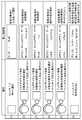
- FIG. 4is a diagram showing an example of condition setting and display of the welding machine according to Embodiment 1 of the present invention.
- FIG. 5is a diagram showing a schematic configuration of a conventional welding machine.
- FIG. 1is a diagram showing an outline of a circuit configuration of a welding machine in the present embodiment.
- FIG. 2is a view showing the appearance of the welder in the present embodiment.
- FIG. 3is a diagram showing an operation portion of the welding machine in the present embodiment.
- FIG. 4shows an example of condition setting and display of the welding machine in the present embodiment.
- an arc welding machinethat performs welding by generating an arc between a welding electrode and a welding object will be described as an example.
- the welding machine of this Embodimenthas an external appearance as shown in FIG. 2, and the setting part 11 and the condition change part 16 which are mentioned later are provided in the front of the welding machine.
- the setting unit 11 and the condition changing unit 16have a configuration as shown in FIG.
- the setting unit 11 of the welding machineincludes a jog dial 1 as an encoder and a plurality of switches 2 that are operated to set information about welding objects and set welding conditions.
- the welding machinealso includes information on the welding object, values of the first welding condition item and the first welding condition item, which are welding condition items that can be set for the welding machine, and settings that are not set for the welding machine.
- a storage unit 12is provided for storing a plurality of sets in which the second welding condition item, which is a possible welding condition item, and the value of the second welding condition item are associated with each other.
- the welding machineincludes a control unit 13, a first display unit 14, and a second display unit 15.
- the control unit 13is a simple setting function for extracting the value of the first welding condition item and the value of the second welding condition item from the storage unit 12 based on the information regarding the welding object set by the setting unit 11. It is a thing with.
- the first display unit 14displays the value of the first welding condition item extracted by the control unit 13.
- the second display unit 15displays the value of the second welding condition item extracted by the control unit 13.
- the LED display for an alphanumeric display, a liquid crystal panel display, etc.can be used as an example of the 1st display part 14 and the 2nd display part 15, the LED display for an alphanumeric display, a liquid crystal panel display, etc. can be used.
- FIG. 3shows an example in which the first display unit 14 is an LED display, and the second display unit 15 is a liquid crystal panel display.
- a wire feed motor drive circuit for feeding wiresis provided in addition to the above-described configuration.
- the main points different from the conventional welding machine described in the background artare the storage unit 12 and the control unit 13 that selects the value of the first welding condition item and the value of the second welding condition item from the storage unit 12. And a first display unit and a second display unit.
- storage part 12is the welding condition item which cannot be set with respect to the information regarding a welding target object, the value of the 1st welding condition item which is a welding condition item which can be set with respect to a welding machine, and a welding machine.
- a plurality of sets in which the values of the second welding condition items are associated with each otherare stored.
- the control unit 13selects the value of the first welding condition item and the value of the second welding condition item from the storage unit 12 based on the information related to the welding object set by the setting unit 11.
- the first display unit 14displays the value of the first welding condition item extracted by the control unit 13.
- the second display unit 15displays the value of the second welding condition item extracted by the control unit 13.
- An operator of the welding machineinputs information related to the welding object by operating the jog dial 1 and the switch 2 constituting the setting unit 11 of the welding machine.
- information regarding a welding target objectthe material of a welding target object, the thickness of a welding target object, the joint shape of a welding part, a welding attitude
- the mode selectionis performed by pressing the switch 1 by the operation (1) in FIG. 4, and the input mode of the welding object is selected. In FIG.
- the material(displayed as “Weighing”), thickness (displayed as “Atsusa”), and joint shape (“tsugite”)
- the welding posture(displayed as “shisei”) is input and set in this order (operations (2) to (5)). Then, by pressing the switch 3 in the operation (6), the welding conditions that cannot be set by the welding machine are displayed from the conditions of the welding object input by the second display unit.
- the storage unit 12cannot set information on the welding object, values of welding condition items that can be set in the welding machine associated with the information on the welding object, and welding machines associated with the information on the welding object. A plurality of sets of values of various welding condition items are stored. Note that the values of these items are the most suitable welding conditions for the input information about the welding object, and are obtained in advance by a welding experiment or the like and stored in the storage unit 12 in advance. .
- ⁇ Information on the welding objectis input by the operation of the setting unit 11 by the operator of the welding machine. Then, the control unit 13 extracts the welding conditions that can be set in the welding machine that matches the input information related to the welding object and the values of the parameters that constitute the welding conditions from the storage unit 12 and sets them in the welding machine. To be displayed on the first display unit 14. Further, the control unit 13 extracts from the storage unit 12 welding conditions that cannot be set in the welding machine that matches the input information related to the welding object, and causes the second display unit 15 to display the welding conditions.
- the welding conditions that can be set in the welding machine, and the welding condition items displayed on the first display unit 14include, for example, a welding method, a welding current, Preflow time, afterflow time, pulse presence / absence selection, pulse current, pulse frequency, pulse width, crater presence / absence selection, initial current, crater current, up slope time, down slope time, AC waveform, AC frequency, EN ratio, AC DC ratio AC / DC frequency and the like.
- a welding voltagecan also be included.
- the welding conditions displayed on the first display unit 14can be set.
- the values of various welding condition itemscan be changed using the condition changing unit 16 shown in FIG.
- the condition switch 18any one of the conditions SW1 to SWn
- the welding condition item to be changedis selected, and then the value is changed by operating the jog dial 17 for changing the welding condition.
- welding condition items that cannot be set in the welding machineand examples of the welding condition items displayed on the second display unit 15 include, for example, a flow rate of shield gas, a diameter of a filler wire, and a non-consumable electrode. Examples include the diameter and the tip angle of the non-consumable electrode. These items are items that cannot be set directly in the welding machine, but are important parameters when welding. And it is also a difficult parameter to set for an operator with little welding experience.
- the value displayed on the first display unit 14is set as a welding condition by the control unit 13 and sent to the welding control unit 6.
- the workerperforms an operation for performing welding in accordance with the welding condition item and its value displayed on the second display unit 15 that displays the welding condition item that cannot be set in the welding machine.
- the second display unit 15displays the shield gas flow rate, the diameter of the filler wire, the diameter of the non-consumable electrode, and the tip angle of the non-consumable electrode as shown in FIG.
- the operatorsets the gas flow rate to 10 L (liter) by operating a gas regulator or the like that is provided outside the welding machine and can change the gas flow rate, and has a diameter as a filler. Is attached to a filler feeder not shown.
- the operatorattaches a non-consumable electrode having a diameter of 2.4 mm and a tip angle of 30 ° to a welding torch (not shown).
- condition switch 18condition SW1 to condition SWn
- the reason why the information displayed on the second display unit 15 is deletedwill be described below.
- the information displayed on the first display unit 14 and the second display unit 15is an optimum value for the welding object that matches the information on the welding object input to the setting unit 11 constituting the welding machine. Is displayed. Therefore, when one value among the values of the welding condition items displayed on the first display unit 14 is changed, the value of the welding condition item displayed on the second display unit 15 is This is because it cannot be said to be an optimum value for the welding object. And the value of a new welding condition item is displayed on the 2nd display part 15 as an optimal value with respect to a welding target object.
- the welding condition suitable for thisis stored by setting information on the welding object using the jog dial 1, the switch 2, or the first display unit 14. It can be set by selecting from the section 12. That is, the welding conditions that can be set in the welding machine can be automatically set in the welding machine based on the information related to the welding object.
- welding conditions that cannot be set in the welding machinecan be displayed on the second display unit 15 and presented to the operator.
- welding conditions that cannot be set in the welding machinecan be displayed on the second display unit 15 and presented to the operator.
- first display unit 14 and the second display unit 15are separately provided.
- first display unit 14 and the second display unit 15are integrated, for example, 1 It can also be one large LCD.
- the condition changing unit 16may not be provided with the jog dial 17, but the information displayed on the first display unit 14 may be changed by the jog dial 1 provided in the setting unit 11.
- the welding machine of the present inventionis a welding machine that uses a welding torch connected thereto, and is a setting unit 11, a storage unit 12, a control unit 13, a first display unit 14, and a second display.
- the setting part 11sets the information regarding a welding target object.
- the storage unit 12includes information on the welding object, a value of a first welding condition item that is a welding condition item that can be set for the welding machine, and a welding condition item that cannot be set for the welding machine. A plurality of sets in which the values of the two welding condition items are associated are stored.
- the control unit 13selects the value of the first welding condition item and the value of the second welding condition item from the storage unit 12 based on the information related to the welding object set by the setting unit 11.
- the first display unit 14displays the value of the first welding condition item extracted by the control unit 13.
- the second display unit 15displays the value of the second welding condition item extracted by the control unit 13.
- control unit 5determines the value of the second welding condition item and the second value from the storage unit 12 based on the information related to the welding object set by the setting unit 11. It is good also as a structure which displays the value of the 2nd welding condition item and the 2nd welding condition item which the control part 5 selected on the 2nd display part 15 selected.
- the welding machine of the present inventionfurther includes a condition changing unit 16 that changes the value of the first welding condition item displayed on the first display unit 14.
- the display content displayed on the second display unit 15may be erased when the value of the displayed first welding condition item is changed.
- the second welding condition itemis at least one of a flow rate of the shielding gas, a diameter of the filler wire, a diameter of the non-consumable electrode, and a tip angle of the non-consumable electrode. It is good also as a structure containing two.
- the first welding condition itemsare welding method, welding current, welding voltage, preflow gas time, afterflow time, pulse presence / absence selection, pulse current, pulse frequency, It may be configured to include at least one of pulse width, crater presence / absence selection, initial current, crater current, up slope time, down slope time, AC waveform, AC frequency, EN ratio, AC / DC ratio, and AC / DC frequency.
- This configurationmakes it possible to easily set the welding conditions and enhance the convenience for the operator.
- the welding machine of the present inventionmay be configured such that the information on the welding object includes at least one of the material of the welding object, the plate thickness, the joint shape, and the welding posture.
- the most suitable welding conditionscan be set by using what is obtained in advance by a welding experiment or the like and stored in the storage unit 12 in advance. Thereby, even an operator who does not have knowledge about welding conditions cannot know the information that is important for performing welding although it cannot be set in the welding machine. Therefore, when the worker takes action based on the information, better welding can be realized, and convenience can be further enhanced.
- the welding machine of the present inventionmay be configured such that the first display unit 14 and the second display unit 15 are integrated into one display unit.
- This configurationmakes it possible to view a list of necessary information on a single display unit, further enhancing the convenience for the operator.
- the welding machine of the present inventioncan easily set the welding conditions and can improve the convenience of the operator, and is industrially used as a welding machine used when performing various weldings by changing the welding conditions. Useful.
Landscapes
- Engineering & Computer Science (AREA)
- Physics & Mathematics (AREA)
- Plasma & Fusion (AREA)
- Mechanical Engineering (AREA)
- Arc Welding Control (AREA)
Abstract
Description
Translated fromJapanese本発明は、アークを発生させて加工対象物を加工する装置、特にデジタル制御を行うためのCPU等のプログラマブルデバイスを搭載した溶接機に関する。The present invention relates to an apparatus for processing an object to be processed by generating an arc, and particularly to a welding machine equipped with a programmable device such as a CPU for performing digital control.
一般に、電極からアークを発生させて加工対象物である母材を溶融する溶接機等の装置には、電極と母材との間で発生するアークの電流や電圧を制御するための出力制御回路と、アークを外気から保護するシールドガスを制御するためのガス制御回路と、アーク発生を補助するためのスタート回路が備えられている。なお、消耗電極式アーク溶接機の場合には、これらに加えて、消耗電極である溶接用ワイヤの送給を制御するための送給制御回路が備えられている。In general, in an apparatus such as a welding machine that generates an arc from an electrode and melts a base material that is a workpiece, an output control circuit for controlling the current and voltage of the arc generated between the electrode and the base material And a gas control circuit for controlling the shield gas for protecting the arc from the outside air, and a start circuit for assisting the generation of the arc. In addition, in the case of a consumable electrode type arc welder, in addition to these, a feed control circuit for controlling the feed of a welding wire that is a consumable electrode is provided.
近年、更なる機器の高性能化を実現するため、これら出力制御回路やガス制御回路やスタート制御回路は、CPU(Central Processing Unit)等のプログラマブルデバイスを用いて構成され、ソフトウェアにより制御されるのが一般的となってきており、デジタル制御溶接機として普及している。In recent years, these output control circuits, gas control circuits, and start control circuits have been configured using programmable devices such as a CPU (Central Processing Unit) and are controlled by software in order to achieve higher performance of equipment. Have become commonplace and are popular as digitally controlled welders.
このデジタル制御溶接機は、複数の溶接法を備え、各々の溶接法に対して詳細な条件設定が可能となっている。例えば、加工対象物が鉄やステンレスの場合には出力を直流とする直流溶接モードや、加工対象物がアルミニウムの場合には出力を交流出力とする交流溶接モードがある。This digitally controlled welding machine has a plurality of welding methods, and detailed conditions can be set for each welding method. For example, there are a DC welding mode in which the output is DC when the workpiece is iron or stainless steel, and an AC welding mode in which the output is AC output when the workpiece is aluminum.
また、加工対象物の状態に応じて出力をパルス波形とするパルス溶接法と、その時のパルス周波数やパルス幅の条件、あるいは、加工対象物の厚みに応じて変化する出力電流とガスフロー時間等、多くのパラメータの設定に従って溶接が制御される。Also, a pulse welding method in which the output is a pulse waveform according to the state of the workpiece, the conditions of the pulse frequency and pulse width at that time, or the output current and gas flow time that change according to the thickness of the workpiece The welding is controlled according to the settings of many parameters.
デジタル制御溶接機では、これらのパラメータを設定するため、ジョグダイヤルと呼ばれるエンコーダやLED(Light Emitting Diode)表示装置等を備えているものが知られている(例えば、特許文献1参照)。通常これらのパラメータの設定は、溶接作業者の知識や経験、あるいは、取扱説明書の施工条件等を参考に設定される。In order to set these parameters, a digital control welding machine is known which includes an encoder called a jog dial, an LED (Light Emitting Diode) display device, and the like (for example, see Patent Document 1). Normally, these parameters are set with reference to the knowledge and experience of the welding operator or the construction conditions in the instruction manual.
以下、ジョグダイヤルやLED表示装置を備えた従来のアーク溶接機について、図5を用いて説明する。図5は、従来の溶接機の概略構成を示す図である。Hereinafter, a conventional arc welder equipped with a jog dial and an LED display device will be described with reference to FIG. FIG. 5 is a diagram showing a schematic configuration of a conventional welding machine.
図5において、アーク溶接機は操作部4を有しており、操作部4には条件設定用のジョグダイヤル1と、条件設定用のスイッチ2と、英数字表示用のLED表示部3が設けられている。また、アーク溶接機は、制御部5と、溶接制御部6と、出力駆動部7と、シールドガス駆動回路8と、スタート装置駆動回路9と、ワイヤ送給モータ駆動回路10と、を備えている。ここで、制御部5は、操作部4を用いて設定された溶接に関するパラメータに応じて条件を修正して溶接制御を行う。溶接制御部6は、制御部5からの指令に基づいて溶接制御を行う。出力駆動回路7は、溶接制御部6により制御される。In FIG. 5, the arc welding machine has an
以上のように構成された従来のアーク溶接機について、その動作を説明する。The operation of the conventional arc welder configured as described above will be described.
一般に、アーク溶接機は、消耗電極式アーク溶接機と非消耗電極式アーク溶接機の2種類に大別される。消耗電極式アーク溶接機では、溶接用ワイヤを溶接箇所に供給するためのワイヤ送給用モータの回転設定を行うが、この設定以外は、両溶接機はほぼ同様の条件設定項目を備えている。主な条件設定項目としては、交流出力または直流出力の選択、溶接電流値、ガスフロー時間、パルス溶接を行うか否かのパルス溶接の選択等がある。Generally, arc welders are roughly classified into two types: consumable electrode arc welders and non-consumable electrode arc welders. In the consumable electrode type arc welding machine, the rotation setting of the wire feeding motor for supplying the welding wire to the welding point is performed. Except for this setting, both welding machines have almost the same condition setting items. . Main condition setting items include selection of AC output or DC output, welding current value, gas flow time, selection of pulse welding to determine whether or not to perform pulse welding, and the like.
なお、アーク溶接機に関し、初期状態では、工場出荷時の初期値が溶接条件のパラメータとして設定されている。作業者は、スイッチ2を操作することにより溶接条件項目を選択し、ジョグダイヤル1の操作により選択した溶接条件項目に対する数値を設定する。これにより制御部5における溶接条件の設定が変更される。溶接条件項目の設定された数値はLED表示部3に表示され、作業者が確認を行うことができる。そして、溶接条件項目毎の値の設定を行うことにより、目的とする溶接に必要な条件を設定し、その後実際に溶接を開始する。制御部5で決定された各設定値は溶接制御部6に送られる。溶接制御部6は、送られてきた設定値に従って出力駆動回路7やシールドガス駆動回路8やスタート装置駆動回路9を動作させる。これにより、作業者が設定した溶接条件で溶接を行うことができる。In addition, regarding the arc welder, in the initial state, the factory default value is set as a parameter for the welding condition. The operator selects a welding condition item by operating the
このように従来の溶接機を使用すれば、溶接条件の設定をデジタルで数値入力することができ、正確な条件設定が可能となる。If the conventional welding machine is used in this way, it is possible to input the welding condition setting numerically and to set the accurate condition.
しかしながら、上述のような従来の溶接機では、溶接条件の設定を行う場合、溶接法の選択や溶接電流の設定を始め、多くの設定項目について作業者の知識や経験にもとづいて設定するか、あるいは、取扱説明書等の参考資料にもとづいて設定する必要がある。そのため、設定に時間がかかり、また、熟練作業者でなければ正しい設定ができないという課題を有していた。However, in the conventional welding machine as described above, when setting the welding conditions, starting with the selection of the welding method and the setting of the welding current, whether to set many setting items based on the knowledge and experience of the operator, Alternatively, it is necessary to set based on reference materials such as an instruction manual. For this reason, it takes time to set, and there is a problem that only a skilled worker can make a correct setting.
上記課題を解決するために、本発明のアーク溶接機は、溶接トーチを接続して使用する溶接機であって、溶接対象物に関する情報を設定するための設定部と、上記溶接対象物に関する情報と上記溶接機に対して設定可能な溶接条件項目である第1の溶接条件項目の値と上記溶接機に対して設定不可能な溶接条件項目である第2の溶接条件項目の値とを対応付けた組を複数記憶する記憶部と、上記設定部により設定された上記溶接対象物に関する情報に基づいて上記記憶部から第1の溶接条件項目の値と第2の溶接条件項目の値を選択する制御部と、上記制御部が抽出した上記第1の溶接条件項目の値を表示する第1の表示部と、上記制御部が抽出した上記第2の溶接条件項目の値を表示する第2の表示部と、を備えたものである。In order to solve the above problems, an arc welding machine of the present invention is a welding machine that is used by connecting a welding torch, and a setting unit for setting information on a welding object, and information on the welding object Corresponds to the value of the first welding condition item that is a welding condition item that can be set for the welding machine and the value of the second welding condition item that is a welding condition item that cannot be set for the welding machine. A storage unit that stores a plurality of attached sets, and a value of a first welding condition item and a value of a second welding condition item are selected from the storage unit based on information on the welding object set by the setting unit A first display unit for displaying the value of the first welding condition item extracted by the control unit, and a second for displaying the value of the second welding condition item extracted by the control unit. And a display unit.
以上のように、本発明によれば、溶接対象物に関する情報を設定することで、この溶接対象物に適した溶接条件を溶接機に設定することができる。また、溶接機に設定不可能な情報ではあるが溶接に関して重要な情報を表示部に表示して作業者に提示することができる。したがって、溶接性の向上を可能とする溶接機を実現することができる。As described above, according to the present invention, it is possible to set welding conditions suitable for a welding object in the welding machine by setting information on the welding object. Moreover, although it is information that cannot be set in the welding machine, important information regarding welding can be displayed on the display unit and presented to the operator. Therefore, a welder that can improve weldability can be realized.
以下、本発明の実施の形態について、図面を参照しながら説明する。以下の図面においては、同じ構成要素については同じ符号を付しているので説明を省略する場合がある。Hereinafter, embodiments of the present invention will be described with reference to the drawings. In the following drawings, the same components are denoted by the same reference numerals, and the description thereof may be omitted.
(実施の形態1)
本実施の形態の溶接機について、図1から図4を用いて説明する。図1は本実施の形態における溶接機の回路構成の概略を示す図である。図2は本実施の形態における溶接機の外観を示す図である。図3は本実施の形態における溶接機の操作部分を示す図である。図4は、本実施の形態における溶接機の条件設定および表示の一例を示すものである。(Embodiment 1)
The welding machine of this Embodiment is demonstrated using FIGS. 1-4. FIG. 1 is a diagram showing an outline of a circuit configuration of a welding machine in the present embodiment. FIG. 2 is a view showing the appearance of the welder in the present embodiment. FIG. 3 is a diagram showing an operation portion of the welding machine in the present embodiment. FIG. 4 shows an example of condition setting and display of the welding machine in the present embodiment.
なお、本実施の形態では、溶接用の電極と溶接対象物との間でアークを発生させて溶接を行うアーク溶接機を例にして説明する。そして、本実施の形態の溶接機は、図2に示すような外観を有しており、溶接機の正面には後述する設定部11や条件変更部16が設けられている。この設定部11や条件変更部16は、図3に示すような構成を有している。In the present embodiment, an arc welding machine that performs welding by generating an arc between a welding electrode and a welding object will be described as an example. And the welding machine of this Embodiment has an external appearance as shown in FIG. 2, and the
図1において、溶接機の設定部11には、溶接対象物に関する情報の設定や溶接条件を設定するために操作される、エンコーダとしてのジョグダイヤル1と、複数のスイッチ2を備えている。1, the
また、溶接機は、溶接対象物に関する情報と、溶接機に対して設定可能な溶接条件項目である第1の溶接条件項目および第1の溶接条件項目の値と、溶接機に対して設定不可能な溶接条件項目である第2の溶接条件項目および第2の溶接条件項目の値と、を対応付けた組を複数記憶する記憶部12を備えている。The welding machine also includes information on the welding object, values of the first welding condition item and the first welding condition item, which are welding condition items that can be set for the welding machine, and settings that are not set for the welding machine. A
また、溶接機は、制御部13と、第1の表示部14と、第2の表示部15と、を備えている。ここで、制御部13は、設定部11により設定された溶接対象物に関する情報に基づいて記憶部12から第1の溶接条件項目の値と第2の溶接条件項目の値を抽出する簡易設定機能付きのものである。第1の表示部14は、制御部13が抽出した第1の溶接条件項目の値を表示する。第2の表示部15は、制御部13が抽出した第2の溶接条件項目の値を表示する。なお、第1の表示部14と第2の表示部15の例としては、英数字表示用のLED表示器や液晶パネル表示器などを使用することができる。図3では、第1の表示部14をLED表示器とし、第2の表示部15を液晶パネル表示器とした例を示している。Further, the welding machine includes a
なお、本実施の形態の溶接機に関し、図5を用いて説明した従来の溶接機と同じ機能を有するものについては、同一の符号を付して詳細な説明を省略する。In addition, regarding the welding machine according to the present embodiment, those having the same functions as those of the conventional welding machine described with reference to FIG.
また、ここでは記載を省略するが、消耗電極式アーク溶接機の場合には、上述の構成に加えて、ワイヤを送給するためのワイヤ送給モータ駆動回路が設けられる。Although not described here, in the case of a consumable electrode arc welder, a wire feed motor drive circuit for feeding wires is provided in addition to the above-described configuration.
なお、背景技術で説明した従来の溶接機と異なる主な点は、記憶部12と、記憶部12から第1の溶接条件項目の値と第2の溶接条件項目の値を選択する制御部13と、第1の表示部と、第2の表示部と、を設けた点である。ここで、記憶部12は、溶接対象物に関する情報と、溶接機に対して設定可能な溶接条件項目である第1の溶接条件項目の値と、溶接機に対して設定不可能な溶接条件項目である第2の溶接条件項目の値と、を対応付けた組を複数記憶する。制御部13は、設定部11により設定された溶接対象物に関する情報に基づいて、記憶部12から第1の溶接条件項目の値と第2の溶接条件項目の値を選択する。第1の表示部14は、制御部13が抽出した第1の溶接条件項目の値を表示する。第2の表示部15は、制御部13が抽出した第2の溶接条件項目の値を表示する。The main points different from the conventional welding machine described in the background art are the
以上のように構成された溶接機の動作について説明する。溶接機の作業者は、溶接機の設定部11を構成するジョグダイヤル1やスイッチ2を操作することにより、溶接対象物に関する情報を入力する。ここで、溶接対象物に関する情報の例としては、溶接対象物の材質や、溶接対象物の厚みや、溶接部の継ぎ手形状や、溶接姿勢等が挙げられる。図4の操作(1)により、スイッチ1を押すことでモード選択を行い、溶接対象物の入力モードが選択される。図4では、第2の表示部15を用いて、溶接対象物に関する情報として、材質(「ザイリョウ」と表示する。)、厚み(「アツサ」と表示する。)、継ぎ手形状(「ツギテ」と表示する。)、溶接姿勢(「シセイ」と表示する。)の順に入力して設定している例を示している(操作(2)から(5))。そして、操作(6)のスイッチ3を押して第2表示部により入力された溶接対象物の条件等から溶接機で設定不可能な溶接条件を表示する。The operation of the welding machine configured as described above will be described. An operator of the welding machine inputs information related to the welding object by operating the
記憶部12には、溶接対象物に関する情報と、溶接対象物に関する情報に関連づけられた溶接機に設定可能な溶接条件項目の値と、溶接対象物に関する情報に関連づけられた溶接機に設定不可能な溶接条件項目の値の組が複数記憶されている。なお、これらの項目の値は、入力された溶接対象物に関する情報に対して最も適した溶接条件となっており、溶接実験等によって予め求められ、予め記憶部12に記憶されているものである。The
溶接機の作業者による設定部11の操作により溶接対象物に関する情報が入力される。そうすると、制御部13は、入力された溶接対象物に関する情報と合致する溶接機に設定可能な溶接条件および溶接条件を構成する各パラメータの値を記憶部12から抽出して溶接機に設定するとともに、第1の表示部14に表示させる。また、制御部13は、入力された溶接対象物に関する情報と合致する溶接機に設定不可能な溶接条件を記憶部12から抽出して第2の表示部15に表示させる。情報 Information on the welding object is input by the operation of the
ここで、溶接機に設定可能な溶接条件であり、第1の表示部14に表示される溶接条件項目としては、例えば、非消耗電極式アーク溶接機の場合には、溶接法、溶接電流、プリフロー時間、アフターフロー時間、パルス有無選択、パルス電流、パルス周波数、パルス幅、クレータ有無選択、初期電流、クレータ電流、アップスロープ時間、ダウンスロープ時間、交流波形、交流周波数、EN比率、交流直流比率、交流直流周波数などが挙げられる。そして、消耗電極式アーク溶接機の場合には、この他に溶接電圧を含めることもできる。Here, the welding conditions that can be set in the welding machine, and the welding condition items displayed on the
なお、実際に溶接を行った後に、溶接結果を踏まえ、作業者が溶接機に設定可能な溶接条件を変更したい場合もある、そこで、第1の表示部14に表示される溶接機に設定可能な溶接条件項目の値は、図1に示す条件変更部16を用いて変更することが可能である。その変更方法としては、溶接機に設定可能な溶接条件項目毎に対応する条件スイッチ18(条件SW1から条件SWnのいずれか)を押す。これにより、変更を行う溶接条件項目が選択され、その後、溶接条件変更用のジョグダイヤル17を操作して、値の変更が行われる。In addition, after actually performing welding, there is a case where an operator may want to change the welding conditions that can be set in the welding machine based on the welding result. Therefore, the welding conditions displayed on the
また、溶接機に設定不可能な溶接条件項目であり、第2の表示部15に表示される溶接条件項目の例として、例えば、シールドガスの流量や、フィラーワイヤの直径や、非消耗電極の直径や、非消耗電極の先端角度などが挙げられる。なお、これらの項目は溶接機に直接設定することができない項目ではあるが、溶接を行う際には重要なパラメータとなる。そして、溶接経験が少ない作業者にとっては設定が難しいパラメータでもある。Further, welding condition items that cannot be set in the welding machine, and examples of the welding condition items displayed on the
第1の表示部14に表示された値は、制御部13によって溶接条件として設定され、溶接制御部6に送られる。また、作業者は、溶接機に設定不可能な溶接条件項目を表示する第2の表示部15に表示された溶接条件項目とその値に従って溶接を行うための作業を行う。例えば、第2の表示部15に、図4に示すように、シールドガス流量と、フィラーワイヤの径と、非消耗電極の径と、非消耗電極の先端角度が表示されている場合を考える。この場合に、作業者は、溶接機の外部に設けられておりガス流量を変更することのできるガスレギュレータなどを操作することにより、ガス流量を10L(リットル)に設定し、また、フィラーとして直径が1.6mmのものを図示しないフィラー送給装置に取り付ける。また、作業者は、図示しない溶接トーチに、直径が2.4mmであり先端角度が30°である非消耗電極を取り付ける。The value displayed on the
そして、上述のように溶接機に設定可能な溶接条件項目の設定と溶接機に設定不可能な溶接条件項目の設定が完了した後、実際の溶接を行う。Then, after the setting of the welding condition items that can be set in the welding machine and the setting of the welding condition items that cannot be set in the welding machine are completed as described above, actual welding is performed.
なお、条件変更部16を構成する条件スイッチ18(条件SW1から条件SWn)や条件変更のジョグダイヤル17を操作して第1の表示部14に表示された溶接機に設定可能な項目の値を変更した場合、第2の表示部15に表示されていた情報が制御部13により消される。It should be noted that the values of items that can be set in the welding machine displayed on the
このように第2の表示部15に表示されていた情報を消す理由について以下に説明する。第1の表示部14と第2の表示部15に表示される情報は、溶接機を構成する設定部11に入力された溶接対象物に対する情報と一致する溶接対象物に対して最適な値として表示される。そのため、第1の表示部14に表示されている溶接条件項目の値のうち、1つの値でも変更された場合には、第2の表示部15に表示している溶接条件項目の値が、溶接対象物に対して最適な値とはいえなくなってしまうためである。そして、新たな溶接条件項目の値が、溶接対象物に対して最適な値として第2の表示部15に表示される。The reason why the information displayed on the
以上のように、本実施の形態の溶接機によれば、ジョグダイヤル1やスイッチ2や第1の表示部14を用いて溶接対象物に関する情報を設定することで、これに適した溶接条件を記憶部12から選択して設定することができる。すなわち、溶接機に設定可能な溶接条件を溶接対象物に関する情報に基づいて自動的に溶接機に設定することができる。As described above, according to the welding machine of the present embodiment, the welding condition suitable for this is stored by setting information on the welding object using the
これにより、例えば、溶接条件に関する知識を有さない作業者であっても、把握が可能な溶接対象物の情報を目視確認しながら溶接機に入力する。これにより、記憶部12に記憶された溶接条件の中から適切な溶接条件が選択されて溶接機に設定されるので、非常に利便性が高くなる。Thus, for example, even an operator who does not have knowledge about the welding conditions inputs information to the welding machine that can be grasped while visually confirming the information. Thereby, since appropriate welding conditions are selected from the welding conditions memorize | stored in the memory |
さらに、溶接機に設定不可能な溶接条件を第2の表示部15に表示して作業者に提示することができる。これにより、溶接条件に関する知識を有さない作業者であっても、溶接機に設定できないが溶接を行うために重要な情報を知ることができる。また、作業者がその情報に基づいて対応を行うことにより、より良い溶接を実現することが可能となり、利便性をさらに高めることができる。Furthermore, welding conditions that cannot be set in the welding machine can be displayed on the
なお、本実施の形態では、第1の表示部14と第2の表示部15を別に設ける例を示したが、第1の表示部14と第2の表示部15とを一体にして例えば1つの大型LCDとすることもできる。In the present embodiment, an example in which the
また、本実施の形態では、設定部11に設けられたジョグダイヤル1と条件変更部16に設けられたジョグダイヤル17の2つのジョグダイヤルを設けた例を示した。これとは異なり、例えば、条件変更部16にジョグダイヤル17を設けず、設定部11に設けられたジョグダイヤル1により第1の表示部14に表示されている情報を変更するようにしても良い。Further, in the present embodiment, an example in which two jog dials, that is, the
すなわち、本発明の溶接機は、溶接トーチを接続して使用する溶接機であって、設定部11と、記憶部12と、制御部13と、第1の表示部14と、第2の表示部15と、を備えた構成としている。ここで、設定部11は、溶接対象物に関する情報を設定する。記憶部12は、溶接対象物に関する情報と、溶接機に対して設定可能な溶接条件項目である第1の溶接条件項目の値と、溶接機に対して設定不可能な溶接条件項目である第2の溶接条件項目の値と、を対応付けた組を複数記憶する。制御部13は、設定部11により設定された溶接対象物に関する情報に基づいて、記憶部12から第1の溶接条件項目の値と第2の溶接条件項目の値を選択する。第1の表示部14は、制御部13が抽出した第1の溶接条件項目の値を表示する。第2の表示部15は、制御部13が抽出した第2の溶接条件項目の値を表示する。That is, the welding machine of the present invention is a welding machine that uses a welding torch connected thereto, and is a
この構成により、溶接対象物に関する情報を設定することで、この溶接対象物に適した溶接条件を溶接機に設定することができる。また、溶接機に設定不可能な情報ではあるが溶接に関して重要な情報を第2の表示部15に表示して作業者に提示することができる。したがって、溶接性の向上を可能とする溶接機を実現することができる。With this configuration, it is possible to set welding conditions suitable for the welding object in the welding machine by setting information on the welding object. Moreover, although it is information that cannot be set in the welding machine, important information regarding welding can be displayed on the
また、本発明の溶接機は、上記に加えて、制御部5は、設定部11により設定された溶接対象物に関する情報に基づいて、記憶部12から第2の溶接条件項目の値および第2の溶接条件項目を選択し、制御部5が選択した第2の溶接条件項目および第2の溶接条件項目の値を第2の表示部15に表示する構成としてもよい。In addition to the above, in the welding machine according to the present invention, the
この構成により、溶接対象物に関する情報を設定することで、これに適した設定不可能な溶接条件を記憶部12から選択して表示することができる。すなわち、溶接機に設定不可能な溶接条件を溶接対象物に関する情報に基づいて自動的に溶接機に表示することができる。With this configuration, by setting information related to the welding object, it is possible to select and display from the storage unit 12 a welding condition that is not suitable for this setting. That is, the welding conditions that cannot be set in the welding machine can be automatically displayed on the welding machine based on the information related to the welding object.
また、本発明の溶接機は、上記に加えて、第1の表示部14に表示されている第1の溶接条件項目の値を変更する条件変更部16を備え、第1の表示部14に表示されている第1の溶接条件項目の値が変更されると第2の表示部15に表示されている表示内容を消す構成としてもよい。In addition to the above, the welding machine of the present invention further includes a
この構成により、溶接条件項目のうちの少なくとも1つの値が変更された場合に、第2の表示部15に溶接対象物に対して最適な値といえない値が、いつまでも表示されることがない。これにより、最適でない溶接条件が指示されることを防止することができる。With this configuration, when at least one value of the welding condition items is changed, a value that cannot be said to be the optimum value for the welding object is never displayed on the
また、本発明の溶接機は、上記に加えて、第2の溶接条件項目は、シールドガスの流量、フィラーワイヤの直径、非消耗電極の直径および前記非消耗電極の先端角度のうちの少なくとも1つを含む構成としてもよい。In the welding machine of the present invention, in addition to the above, the second welding condition item is at least one of a flow rate of the shielding gas, a diameter of the filler wire, a diameter of the non-consumable electrode, and a tip angle of the non-consumable electrode. It is good also as a structure containing two.
この構成により、溶接条件に関する知識を有さない作業者であっても、把握が可能な溶接対象物の情報を目視確認しながら溶接機に入力することができる。これにより、記憶部12に記憶された溶接条件の中から適切な溶接条件が選択されて溶接機に設定されるので、非常に利便性が高くなる。With this configuration, even an operator who does not have knowledge about welding conditions can input information on a welding object that can be grasped into the welding machine while visually confirming the information. Thereby, since appropriate welding conditions are selected from the welding conditions memorize | stored in the memory |
また、本発明の溶接機は、上記に加えて、第1の溶接条件項目は、溶接法、溶接電流、溶接電圧、プリフローガス時間、アフターフロー時間、パルス有無選択、パルス電流、パルス周波数、パルス幅、クレータ有無選択、初期電流、クレータ電流、アップスロープ時間、ダウンスロープ時間、交流波形、交流周波数、EN比率、交流直流比率および交流直流周波数のうちの少なくとも1つを含む構成としてもよい。In the welding machine of the present invention, in addition to the above, the first welding condition items are welding method, welding current, welding voltage, preflow gas time, afterflow time, pulse presence / absence selection, pulse current, pulse frequency, It may be configured to include at least one of pulse width, crater presence / absence selection, initial current, crater current, up slope time, down slope time, AC waveform, AC frequency, EN ratio, AC / DC ratio, and AC / DC frequency.
この構成により、溶接条件の設定を容易に行うことができるとともに作業者の利便性を高めることができる。This configuration makes it possible to easily set the welding conditions and enhance the convenience for the operator.
また、本発明の溶接機は、上記に加えて、溶接対象物に関する情報は、溶接対象物の材質、板厚、継ぎ手形状および溶接姿勢のうちの少なくとも1つを含む構成としてもよい。In addition to the above, the welding machine of the present invention may be configured such that the information on the welding object includes at least one of the material of the welding object, the plate thickness, the joint shape, and the welding posture.
この構成により、入力された溶接対象物に関する情報に対して最も適した溶接条件を設定することができる。また、最も適した溶接条件は、溶接実験等によって予め求められ、予め記憶部12に記憶されているものを用いて設定することができる。これにより、溶接条件に関する知識を有さない作業者であっても、溶接機に設定できないが溶接を行うために重要な情報を知ることができる。したがって、作業者がその情報に基づいて対応を行うことにより、より良い溶接を実現でき、かつ、利便性をさらに高めることができる。With this configuration, it is possible to set the most suitable welding condition for the input information related to the welding object. Further, the most suitable welding conditions can be set by using what is obtained in advance by a welding experiment or the like and stored in the
また、本発明の溶接機は、上記に加えて、第1の表示部14と第2の表示部15とを一体にして1つの表示部とした構成としてもよい。Moreover, in addition to the above, the welding machine of the present invention may be configured such that the
この構成により、必要な情報を1つの表示部で一覧して見ることができ、作業者の利便性をさらに高めることができる。This configuration makes it possible to view a list of necessary information on a single display unit, further enhancing the convenience for the operator.
本発明の溶接機は、溶接条件の設定を容易に行うことができるとともに作業者の利便性を高めることができ、溶接条件を変えて種々の溶接を行う際に使用する溶接機等として産業上有用である。INDUSTRIAL APPLICABILITY The welding machine of the present invention can easily set the welding conditions and can improve the convenience of the operator, and is industrially used as a welding machine used when performing various weldings by changing the welding conditions. Useful.
1 ジョグダイヤル
2 スイッチ
3 LED表示部
4 操作部
5 制御部
6 溶接制御部
7 出力駆動回路
8 シールドガス駆動回路
9 スタート装置駆動回路
10 ワイヤ送給モータ駆動回路
11 設定部
12 記憶部
13 制御部
14 第1の表示部
15 第2の表示部
16 条件変更部
17 ジョグダイヤル
18 条件スイッチ(条件SW1、・・・、条件SWn)DESCRIPTION OF
Claims (7)
Translated fromJapanese溶接対象物に関する情報を設定するための設定部と、
前記溶接対象物に関する情報と前記溶接機に対して設定可能な溶接条件項目である第1の溶接条件項目の値と前記溶接機に対して設定不可能な溶接条件項目である第2の溶接条件項目の値とを対応付けた組を複数記憶する記憶部と、
前記設定部により設定された前記溶接対象物に関する情報に基づいて前記記憶部から前記第1の溶接条件項目の値と前記第2の溶接条件項目の値を選択する制御部と、
前記制御部が抽出した前記第1の溶接条件項目の値を表示する第1の表示部と、
前記制御部が抽出した前記第2の溶接条件項目の値を表示する第2の表示部と、
を備えた溶接機。A welding machine that connects and uses a welding torch,
A setting section for setting information on the welding object;
Information on the welding object, a value of a first welding condition item that is a welding condition item that can be set for the welding machine, and a second welding condition that is a welding condition item that cannot be set for the welding machine A storage unit for storing a plurality of sets each associated with an item value;
A control unit that selects a value of the first welding condition item and a value of the second welding condition item from the storage unit based on information on the welding object set by the setting unit;
A first display unit for displaying a value of the first welding condition item extracted by the control unit;
A second display unit for displaying a value of the second welding condition item extracted by the control unit;
Welding machine equipped with.
前記制御部が選択した前記第2の溶接条件項目および前記第2の溶接条件項目の値を前記第2の表示部に表示する請求項1記載の溶接機。The control unit selects a value of the second welding condition item and a second welding condition item from the storage unit based on information on the welding object set by the setting unit,
The welding machine according to claim 1, wherein values of the second welding condition item and the second welding condition item selected by the control unit are displayed on the second display unit.
前記第1の表示部に表示されている前記第1の溶接条件項目の値が変更されると前記第2の表示部に表示されている表示内容を消す請求項1または2のいずれか1項に記載の溶接機。A condition changing unit for changing the value of the first welding condition item displayed on the first display unit;
The display content currently displayed on the said 2nd display part will be erase | eliminated, if the value of the said 1st welding condition item currently displayed on the said 1st display part is changed. The welding machine as described in.
Priority Applications (2)
| Application Number | Priority Date | Filing Date | Title |
|---|---|---|---|
| JP2012502363AJP5594356B2 (en) | 2010-09-08 | 2011-07-11 | Welding machine |
| CN201180003849.9ACN102548701B (en) | 2010-09-08 | 2011-07-11 | Welding machine |
Applications Claiming Priority (2)
| Application Number | Priority Date | Filing Date | Title |
|---|---|---|---|
| JP2010200661 | 2010-09-08 | ||
| JP2010-200661 | 2010-09-08 |
Publications (1)
| Publication Number | Publication Date |
|---|---|
| WO2012032702A1true WO2012032702A1 (en) | 2012-03-15 |
Family
ID=45810315
Family Applications (1)
| Application Number | Title | Priority Date | Filing Date |
|---|---|---|---|
| PCT/JP2011/003950WO2012032702A1 (en) | 2010-09-08 | 2011-07-11 | Welding machine |
Country Status (3)
| Country | Link |
|---|---|
| JP (1) | JP5594356B2 (en) |
| CN (1) | CN102548701B (en) |
| WO (1) | WO2012032702A1 (en) |
Cited By (5)
| Publication number | Priority date | Publication date | Assignee | Title |
|---|---|---|---|---|
| JP2013141696A (en)* | 2012-01-12 | 2013-07-22 | Daihen Corp | Arc welding apparatus |
| JP2013141695A (en)* | 2012-01-12 | 2013-07-22 | Daihen Corp | Arc welding apparatus |
| CN105880800A (en)* | 2014-05-13 | 2016-08-24 | 李书进 | Electric welding machine general circuit board design method |
| KR20170105103A (en) | 2015-02-27 | 2017-09-18 | 가부시키가이샤 고베 세이코쇼 | Setting Support Device, Setup Support Method and Program |
| US10625358B2 (en) | 2012-11-07 | 2020-04-21 | Panasonic Intellectual Property Management Co., Ltd. | Arc welder and method for controlling arc welding |
Families Citing this family (1)
| Publication number | Priority date | Publication date | Assignee | Title |
|---|---|---|---|---|
| CN112719524B (en)* | 2020-12-23 | 2022-08-09 | 深圳市兴科瑞拓科技有限公司 | Method, system, terminal and storage medium for automatically adjusting parameters of welding machine |
Citations (4)
| Publication number | Priority date | Publication date | Assignee | Title |
|---|---|---|---|---|
| JPS56160877A (en)* | 1980-05-16 | 1981-12-10 | Hitachi Seiko Ltd | Controller for welding machine |
| JPH01113174A (en)* | 1987-10-23 | 1989-05-01 | Hitachi Ltd | Automatic setting device for welding condition |
| JPH01181970A (en)* | 1988-01-14 | 1989-07-19 | Amada Co Ltd | Method and equipment for welding |
| JP2004223555A (en)* | 2003-01-22 | 2004-08-12 | Souki Kk | Arc welding machine |
Family Cites Families (5)
| Publication number | Priority date | Publication date | Assignee | Title |
|---|---|---|---|---|
| JPS5970469A (en)* | 1982-10-14 | 1984-04-20 | Mitsubishi Electric Corp | Dc arc welding device |
| JPH01321078A (en)* | 1988-06-23 | 1989-12-27 | Mitsubishi Electric Corp | Pulsed arc welding power source |
| JP3259496B2 (en)* | 1993-12-09 | 2002-02-25 | 株式会社ダイヘン | Pulse MAG welding arc start control method |
| JP3844004B1 (en)* | 2005-05-31 | 2006-11-08 | 松下電器産業株式会社 | Pulse arc welding control method and pulse arc welding apparatus |
| CN101309773B (en)* | 2006-10-19 | 2012-07-18 | 松下电器产业株式会社 | Arc welding control method and arc welding device |
- 2011
- 2011-07-11JPJP2012502363Apatent/JP5594356B2/enactiveActive
- 2011-07-11WOPCT/JP2011/003950patent/WO2012032702A1/enactiveApplication Filing
- 2011-07-11CNCN201180003849.9Apatent/CN102548701B/enactiveActive
Patent Citations (4)
| Publication number | Priority date | Publication date | Assignee | Title |
|---|---|---|---|---|
| JPS56160877A (en)* | 1980-05-16 | 1981-12-10 | Hitachi Seiko Ltd | Controller for welding machine |
| JPH01113174A (en)* | 1987-10-23 | 1989-05-01 | Hitachi Ltd | Automatic setting device for welding condition |
| JPH01181970A (en)* | 1988-01-14 | 1989-07-19 | Amada Co Ltd | Method and equipment for welding |
| JP2004223555A (en)* | 2003-01-22 | 2004-08-12 | Souki Kk | Arc welding machine |
Cited By (7)
| Publication number | Priority date | Publication date | Assignee | Title |
|---|---|---|---|---|
| JP2013141696A (en)* | 2012-01-12 | 2013-07-22 | Daihen Corp | Arc welding apparatus |
| JP2013141695A (en)* | 2012-01-12 | 2013-07-22 | Daihen Corp | Arc welding apparatus |
| US10625358B2 (en) | 2012-11-07 | 2020-04-21 | Panasonic Intellectual Property Management Co., Ltd. | Arc welder and method for controlling arc welding |
| CN105880800A (en)* | 2014-05-13 | 2016-08-24 | 李书进 | Electric welding machine general circuit board design method |
| CN105880800B (en)* | 2014-05-13 | 2020-04-14 | 广东联洋科技有限公司 | Design method of universal circuit board of electric welding machine |
| KR20170105103A (en) | 2015-02-27 | 2017-09-18 | 가부시키가이샤 고베 세이코쇼 | Setting Support Device, Setup Support Method and Program |
| US10994359B2 (en) | 2015-02-27 | 2021-05-04 | Kobe Steel, Ltd. | Setting assistance device, setting assistance method, and program |
Also Published As
| Publication number | Publication date |
|---|---|
| CN102548701B (en) | 2014-11-26 |
| CN102548701A (en) | 2012-07-04 |
| JPWO2012032702A1 (en) | 2013-12-12 |
| JP5594356B2 (en) | 2014-09-24 |
Similar Documents
| Publication | Publication Date | Title |
|---|---|---|
| US20230150049A1 (en) | Method for setting welding parameters | |
| US7781700B2 (en) | User interface for welding power supply | |
| CN102834212B (en) | Welding condition determining method, and welding device | |
| JP5594356B2 (en) | Welding machine | |
| US10773328B2 (en) | Welding system user interface having a color display for setting welding parameters | |
| US20160311045A1 (en) | System and method for setting welding parameters | |
| CN113458546A (en) | System and method for controlling welding parameter command limits | |
| EP3271106B1 (en) | Welding system and method | |
| JP2010201499A (en) | Arc welding machine | |
| CN103221172B (en) | Welding machine | |
| CN111843112B (en) | Method and device for controlling welding power and preheating power | |
| JP6139285B2 (en) | Arc welding machine | |
| JP6583958B2 (en) | Power supply apparatus for welding and control method | |
| JP5556734B2 (en) | Welding system and robot controller for welding system | |
| KR20250149892A (en) | Power supply apparatus for heat processing | |
| JP2018202466A (en) | Welding condition setting device and welding condition setting method |
Legal Events
| Date | Code | Title | Description |
|---|---|---|---|
| WWE | Wipo information: entry into national phase | Ref document number:201180003849.9 Country of ref document:CN | |
| WWE | Wipo information: entry into national phase | Ref document number:2012502363 Country of ref document:JP | |
| WWE | Wipo information: entry into national phase | Ref document number:117/KOLNP/2012 Country of ref document:IN | |
| 121 | Ep: the epo has been informed by wipo that ep was designated in this application | Ref document number:11823185 Country of ref document:EP Kind code of ref document:A1 | |
| NENP | Non-entry into the national phase | Ref country code:DE | |
| 122 | Ep: pct application non-entry in european phase | Ref document number:11823185 Country of ref document:EP Kind code of ref document:A1 |