WO2012014348A1 - Cell module and cell pack - Google Patents
Cell module and cell packDownload PDFInfo
- Publication number
- WO2012014348A1 WO2012014348A1PCT/JP2011/001411JP2011001411WWO2012014348A1WO 2012014348 A1WO2012014348 A1WO 2012014348A1JP 2011001411 WJP2011001411 WJP 2011001411WWO 2012014348 A1WO2012014348 A1WO 2012014348A1
- Authority
- WO
- WIPO (PCT)
- Prior art keywords
- chamber
- battery
- battery module
- inert fluid
- combustible gas
- Prior art date
Links
Images


Classifications
- H—ELECTRICITY
- H01—ELECTRIC ELEMENTS
- H01M—PROCESSES OR MEANS, e.g. BATTERIES, FOR THE DIRECT CONVERSION OF CHEMICAL ENERGY INTO ELECTRICAL ENERGY
- H01M10/00—Secondary cells; Manufacture thereof
- H01M10/04—Construction or manufacture in general
- H01M10/0431—Cells with wound or folded electrodes
- H—ELECTRICITY
- H01—ELECTRIC ELEMENTS
- H01M—PROCESSES OR MEANS, e.g. BATTERIES, FOR THE DIRECT CONVERSION OF CHEMICAL ENERGY INTO ELECTRICAL ENERGY
- H01M10/00—Secondary cells; Manufacture thereof
- H01M10/05—Accumulators with non-aqueous electrolyte
- H01M10/052—Li-accumulators
- H01M10/0525—Rocking-chair batteries, i.e. batteries with lithium insertion or intercalation in both electrodes; Lithium-ion batteries
- H—ELECTRICITY
- H01—ELECTRIC ELEMENTS
- H01M—PROCESSES OR MEANS, e.g. BATTERIES, FOR THE DIRECT CONVERSION OF CHEMICAL ENERGY INTO ELECTRICAL ENERGY
- H01M10/00—Secondary cells; Manufacture thereof
- H01M10/05—Accumulators with non-aqueous electrolyte
- H01M10/058—Construction or manufacture
- H01M10/0587—Construction or manufacture of accumulators having only wound construction elements, i.e. wound positive electrodes, wound negative electrodes and wound separators
- H—ELECTRICITY
- H01—ELECTRIC ELEMENTS
- H01M—PROCESSES OR MEANS, e.g. BATTERIES, FOR THE DIRECT CONVERSION OF CHEMICAL ENERGY INTO ELECTRICAL ENERGY
- H01M10/00—Secondary cells; Manufacture thereof
- H01M10/34—Gastight accumulators
- H—ELECTRICITY
- H01—ELECTRIC ELEMENTS
- H01M—PROCESSES OR MEANS, e.g. BATTERIES, FOR THE DIRECT CONVERSION OF CHEMICAL ENERGY INTO ELECTRICAL ENERGY
- H01M10/00—Secondary cells; Manufacture thereof
- H01M10/34—Gastight accumulators
- H01M10/345—Gastight metal hydride accumulators
- H—ELECTRICITY
- H01—ELECTRIC ELEMENTS
- H01M—PROCESSES OR MEANS, e.g. BATTERIES, FOR THE DIRECT CONVERSION OF CHEMICAL ENERGY INTO ELECTRICAL ENERGY
- H01M50/00—Constructional details or processes of manufacture of the non-active parts of electrochemical cells other than fuel cells, e.g. hybrid cells
- H01M50/20—Mountings; Secondary casings or frames; Racks, modules or packs; Suspension devices; Shock absorbers; Transport or carrying devices; Holders
- H01M50/204—Racks, modules or packs for multiple batteries or multiple cells
- H01M50/207—Racks, modules or packs for multiple batteries or multiple cells characterised by their shape
- H01M50/213—Racks, modules or packs for multiple batteries or multiple cells characterised by their shape adapted for cells having curved cross-section, e.g. round or elliptic
- H—ELECTRICITY
- H01—ELECTRIC ELEMENTS
- H01M—PROCESSES OR MEANS, e.g. BATTERIES, FOR THE DIRECT CONVERSION OF CHEMICAL ENERGY INTO ELECTRICAL ENERGY
- H01M50/00—Constructional details or processes of manufacture of the non-active parts of electrochemical cells other than fuel cells, e.g. hybrid cells
- H01M50/30—Arrangements for facilitating escape of gases
- H01M50/342—Non-re-sealable arrangements
- H—ELECTRICITY
- H01—ELECTRIC ELEMENTS
- H01M—PROCESSES OR MEANS, e.g. BATTERIES, FOR THE DIRECT CONVERSION OF CHEMICAL ENERGY INTO ELECTRICAL ENERGY
- H01M2200/00—Safety devices for primary or secondary batteries
- H—ELECTRICITY
- H01—ELECTRIC ELEMENTS
- H01M—PROCESSES OR MEANS, e.g. BATTERIES, FOR THE DIRECT CONVERSION OF CHEMICAL ENERGY INTO ELECTRICAL ENERGY
- H01M2200/00—Safety devices for primary or secondary batteries
- H01M2200/10—Temperature sensitive devices
- H—ELECTRICITY
- H01—ELECTRIC ELEMENTS
- H01M—PROCESSES OR MEANS, e.g. BATTERIES, FOR THE DIRECT CONVERSION OF CHEMICAL ENERGY INTO ELECTRICAL ENERGY
- H01M2200/00—Safety devices for primary or secondary batteries
- H01M2200/20—Pressure-sensitive devices
- Y—GENERAL TAGGING OF NEW TECHNOLOGICAL DEVELOPMENTS; GENERAL TAGGING OF CROSS-SECTIONAL TECHNOLOGIES SPANNING OVER SEVERAL SECTIONS OF THE IPC; TECHNICAL SUBJECTS COVERED BY FORMER USPC CROSS-REFERENCE ART COLLECTIONS [XRACs] AND DIGESTS
- Y02—TECHNOLOGIES OR APPLICATIONS FOR MITIGATION OR ADAPTATION AGAINST CLIMATE CHANGE
- Y02E—REDUCTION OF GREENHOUSE GAS [GHG] EMISSIONS, RELATED TO ENERGY GENERATION, TRANSMISSION OR DISTRIBUTION
- Y02E60/00—Enabling technologies; Technologies with a potential or indirect contribution to GHG emissions mitigation
- Y02E60/10—Energy storage using batteries
Definitions
- the present inventionrelates to a battery module and a battery pack used for an electric vehicle or the like, and more particularly, to electrically connect a battery module containing a secondary battery using a non-aqueous electrolyte typified by a lithium ion battery or the like and a plurality of battery modules.
- the battery packconnected to.
- non-aqueous secondary batteriesin particular lithium ion secondary batteries, have features such as light weight, high electromotive force, and high energy density. Therefore, mobile phones, digital cameras, video cameras, notebooks, etc. As a power source for driving various types of portable electronic devices such as personal computers and mobile communication devices, demand is increasing.
- This battery moduleneeds to improve safety against abnormal situations such as automobile collision.
- an inert fluidsuch as a fire extinguisher is used in order to prevent battery smoke and ignition when abnormal. It is designed to be injected into the unit cell.
- Patent Document 2a sealed container containing a fire extinguisher is installed in a chamber containing a battery module, and when the abnormality occurs, the sealed container is destroyed and the fire extinguisher acts on the unit cell. Things are listed.
- the inert fluidis less likely to act on the unit cell due to the presence of combustible gas generated from the unit cell when an abnormality occurs than in the technique of Patent Document 1, so There is a problem that it is difficult to reduce the risk.
- the present inventionhas been made in view of such problems, and provides a battery module that can reduce the risk of firing or firing when an abnormality occurs in a unit cell, and a battery pack in which a plurality of the battery modules are connected. Objective.
- a battery moduleincludes a plurality of unit cells, a battery storage case having a chamber for storing the plurality of unit cells, and an opening that opens to the battery storage case, and provides an inert fluid when an abnormality occurs in the unit cells.
- an inert fluidis introduced into the chamber from the fluid inlet, and the combustible gas generated from the unit cell is discharged from the gas outlet.
- the combustible gas from the unit cellis quickly discharged from the gas discharge port, it is possible to reduce the risk of burning or ignition due to retention of high-temperature combustible gas. Further, since the combustible gas is quickly discharged from the gas discharge port, the inert fluid can be made to act on the unit cell accurately, and as a result, the risk of burning or firing the battery can be reduced.
- FIG. 3is a cross-sectional view schematically showing the configuration of a unit cell used in the battery module in Embodiment 1.
- FIG.It is a figure explaining the outline of the battery module which concerns on Embodiment 1.
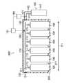
- FIG. 1is a cross-sectional view schematically showing a configuration of a unit cell used in the battery module in the present embodiment.
- a unit cell 100 used in the battery module of the present inventionfor example, a cylindrical lithium ion secondary battery as shown in FIG. 1 can be adopted.
- This lithium ion secondary batteryis provided with a safety valve mechanism that releases gas to the outside of the battery when the pressure in the battery increases due to the occurrence of an abnormality such as an internal short circuit.
- an abnormalitysuch as an internal short circuit.
- an electrode group 104 in which a positive electrode 101 and a negative electrode 102 are wound through a separator 103is housed in a battery case 107 together with a non-aqueous electrolyte.
- Insulating plates 109 and 110are arranged above and below the electrode group 104, the positive electrode 101 is joined to the filter 112 via the positive electrode lead 105, and the negative electrode 102 is also connected to the negative electrode terminal via the negative electrode lead 106. Is joined to the bottom.
- a paste containing a positive electrode active material and a negative electrode active materialis applied to the surfaces of the positive electrode and the negative electrode, respectively.
- the positive electrode active materialfor example LiMn 2 O 4, LiCoO 2, LiNiO 3 , etc.
- the negative electrode active materialfor example, one or more negative electrode active materials used in lithium ion batteries, such as amorphous carbon and graphite carbon, can be used without particular limitation.
- non-aqueous electrolytefor example, ethylene carbonate, propylene carbonate, butylene carbonate, vinylene carbonate, dimethyl carbonate, diethyl carbonate, ethyl methyl carbonate and the like can be used.
- the filter 112is connected to the inner cap 113, and the protrusion of the inner cap 113 is joined to the metal valve plate 114. Further, the valve plate 114 is connected to a terminal plate 108 that also serves as a positive electrode terminal. The terminal plate 108, the valve plate 114, the inner cap 113, and the filter 112 are integrated to seal the opening of the battery case 107 via the gasket 111.
- valve body 114When an abnormality such as an internal short circuit occurs in the unit cell 100 and the pressure in the unit cell 100 increases, the valve body 114 swells toward the terminal plate 108 and the inner cap 113 and the valve body 114 are disconnected. The current path is interrupted. When the pressure in the unit cell 100 further increases, the valve body 114 is broken. As a result, the gas generated in the unit cell 100 is discharged to the outside through the through hole 112a of the filter 112, the through hole 113a of the inner cap 113, the tear of the valve body 114, and the opening 108a of the terminal plate 108. Is done.
- the safety valve mechanism that discharges the gas generated in the unit cell 100 to the outsideis not limited to the structure shown in FIG.
- a configuration in which the valve body is opened away from the valve seatcan be employed.
- FIG. 2is a diagram for explaining the outline of the battery module 800 according to the present embodiment.
- the battery module 800includes a casing-shaped battery housing case 200 made of, for example, polycarbonate resin, and a plurality of unit cells 100 housed in the battery housing case 200.
- the unit cells 100are arranged in parallel in one direction indicated by an arrow 171 and are electrically connected to each other, for example, in parallel.
- Each unit cell 100is fixed at a restricted position by a rib 211 formed on the bottom 210 of the battery housing case 200.
- Each unit cell 100can be held together by a battery holding frame.
- a fluid introduction port 120 for allowing an inert fluid to be introduced into the battery housing case 200 when a battery abnormality occursis opened above one wall surface of the battery housing case 200.
- the fluid introduction port 120is provided with an introduction valve 121. Normally, the introduction valve 121 is closed, and the inside of the battery housing case 200 is kept sealed. When the inert fluid is ejected from the inert fluid supply means 140 described later, the introduction valve 121 is opened and the inert fluid is supplied into the battery housing case 200.
- the introduction valve 121is a destruction valve that is destroyed by, for example, the dynamic pressure of the inert fluid ejected from the inert fluid supply unit 140.
- a gas discharge port 130is provided for discharging the combustible gas generated from the battery from the battery housing case 200 when a battery abnormality occurs.
- the gas discharge port 130 and the fluid introduction port 120are disposed, for example, at positions facing each other in the horizontal direction.
- the gas discharge port 130is provided with a discharge valve 131 similar to the introduction valve 121. Normally, the discharge valve 131 is closed, and the inside of the battery housing case 200 is kept sealed.
- the inert fluid supply unit 140is provided in the middle of the tank 141 in which the inert fluid is stored, the guide path 142 that guides the inert fluid stored in the tank 141 to the fluid inlet 120, and the guide path 142.
- An on-off valve 143 that opens and closes the guide path 142 and an actuator 144 that opens and closes the on-off valve 143are provided.
- the inert fluidis an inert gas, liquid, or gel.
- the inert fluidis not particularly limited.
- non-reactive gassuch as nitrogen, helium, argon, neon, krypton, xenon, carbon dioxide, or combustion reaction such as perfluoroketone is terminated or A fire extinguisher that prevents fire.
- a solid componentsuch as powder or fine particles in the inert fluid.
- sodium hydrogen carbonate powder in carbon dioxideWhen sodium bicarbonate is heated to a high temperature, it absorbs heat, generating carbon dioxide and water vapor, lowering the temperature in the battery housing case 200, keeping it in an inert atmosphere, preventing the occurrence of fire, and terminating the combustion reaction.
- a pressure sensor 150 that detects the internal pressure of the battery housing case 200is provided on the ceiling of the battery housing case 200.
- An inert fluid supply control means 151is connected to the pressure sensor 150. Based on the detection result of the pressure sensor 150, the inert fluid supply control unit 151 discharges the combustible gas from the gas discharge port 130 when the internal pressure in the battery housing case 200 is higher than a predetermined set pressure.
- the on-off valve 143is opened by operating the actuator 144, and an inert fluid is injected from the tank 141 into the battery housing case 200.
- the battery module 800having the above configuration will be described.
- the battery module 800is mounted on a hybrid vehicle, and an abnormality occurs in the battery module 800 due to, for example, a flammable electrolyte ignited due to a collision of the vehicle.
- Combustible gasis generated from the battery due to the abnormality of the battery module 800.
- This combustible gasaccumulates in the chamber containing the unit cell, and the pressure in the chamber rises.
- the pressure in the battery housing case 200is detected by the pressure sensor 150.
- the inert fluid supply control means 151operates the actuator 144 to open the on-off valve 143. Make it.
- the on-off valve 143When the on-off valve 143 is opened, an inert fluid flows from the tank 141, the introduction valve 121 is destroyed by the dynamic pressure of the inert fluid, the fluid inlet 120 is opened, and the inert fluid is introduced into the battery housing case 200. . Since the pressure in the battery housing case 200 is detected by the pressure sensor 150, the inert fluid can be made to act automatically and quickly even in an emergency.
- the inert fluid introduced from one wall surface of the battery housing case 200 in this waythe combustible gas generated from the battery is pushed to the other wall surface of the battery housing case 200 as shown by the arrow 172,
- the exhaust valve 131 of the gas exhaust port 130is destroyed by the dynamic pressure of the flow, and the combustible gas is exhausted from the gas exhaust port 130.
- the inert fluid introduced from the gas inlet 120acts on the unit cell 100 as indicated by an arrow 173. In this manner, the combustible gas is discharged from the gas discharge port 130, and the inert gas is filled in the battery housing case 200 to act on the unit cell 100, so that the combustion or ignition of the battery in the event of an abnormality occurs. Risk can be reduced.
- the pressure sensor 150is provided in the battery housing case 200.
- a battery housingis provided instead of the pressure sensor 150.
- a temperature sensor for detecting the temperature of the case 200is provided, and the inert fluid supply control means 151 is based on the detection result of the temperature sensor, and when the temperature in the battery housing case 200 is higher than a predetermined set temperature, the inert fluid Can be injected into the battery housing case 200 to discharge the combustible gas from the gas discharge port 130.
- a gas sensor for detecting the combustible gas in the battery housing case 200is provided, and the inert fluid supply control means 151 is provided in the battery housing case 200 based on the detection result of the gas sensor.
- the pressure sensor 150, the temperature sensor, and the gas sensormay be provided alone or in combination.
- the pressure sensor 150that detects the internal pressure of the battery housing case 200 is provided, and when the internal pressure in the battery housing case 200 is higher than a predetermined set pressure, the inert fluid supply control means. 151, the inert fluid is automatically injected into the battery housing case 200.
- the inert fluidis manually housed in the battery using a fire extinguisher. The case where it injects in case 200 is demonstrated.
- FIG. 3is a diagram for explaining an outline of the battery module 800 that uses the fire extinguisher 500 to inject an inert fluid into the battery housing case 200.
- one end (downstream side) of the extinguishing agent introduction path 122 for introducing the extinguishing agentis connected to the fluid introduction port 120.
- the other end (upstream side) of the extinguishant introduction path 122is connected to a nozzle insertion port 123 for inserting the extinguishing agent nozzle 510 of the extinguisher 500.
- the gas discharge port 130is connected to one end of a discharge path 132 for discharging the combustible gas, and the other end is provided with an exhaust port 133. In this way, the gas discharge port 130 is provided. Is disposed at an extended position as the exhaust port 133.
- the nozzle insertion port 123is provided with identification means for identifying the user of the fire extinguisher 500 between the nozzle insertion port 123 and the exhaust port 133.
- this identification meansis not particularly limited, a means having distinctiveness can be used from color, shape, or a combination thereof. For example, a fluorescent color sticker or an arrow shape indicating the location of the nozzle insertion port 123 is used. Or the like can be used.
- the operation of the battery module 800 having the above configurationwill be described.
- an abnormalityoccurs in the battery module 800 due to, for example, a flammable electrolyte ignited due to a collision of an automobile on which the battery module 800 is mounted.
- Combustible gasis generated from the battery due to the abnormality of the battery module 800.
- a user of an automobileuses, for example, a fire extinguisher 500 installed in the car in advance, and inserts the fire extinguishing agent nozzle 510 of the fire extinguisher 500 into the nozzle insertion port 123.
- the user of the fire extinguisher 500can accurately enter the nozzle insertion port 123 without making a mistake with the exhaust port 133 even in an emergency in which an abnormality occurs in the battery module 800.
- the fire extinguisher nozzle 510 of the fire extinguisher 500can be inserted. Thereafter, the fire extinguisher 500 is operated, and the inert fluid is introduced into the battery housing case 200.
- the combustible gasis pushed toward the gas outlet 130 as indicated by the arrow 172, and the inert fluid acts on the unit cell 100 as indicated by the arrow 173.
- the combustible gasis discharged from the gas discharge port 130, and the inert gas is filled in the battery housing case 200 to act on the unit cell 100, so that the combustion or ignition of the battery in the event of an abnormality occurs. Risk can be reduced.
- the identification unit provided in the nozzle insertion port 123is a unit having identification from color, shape, or a combination thereof, but is not limited to such an embodiment.
- the base structure of the nozzle insertion port 123can be fitted to the fire extinguisher nozzle 510, but the base structure of the exhaust port 133 cannot be fitted to the fire extinguisher nozzle 510. It is also possible to distinguish between the nozzle insertion port 123 and the exhaust port 133.
- the combustible gasis discharged into the battery housing case 200.
- a dedicated gas for discharging the combustible gas into the battery housing case 200is used.
- An exhaust chamberis provided.
- FIG. 4is a diagram illustrating an outline of a battery module 800 having a dedicated exhaust chamber 202 for discharging combustible gas.
- the battery housing case 200is formed on the partition wall 203 disposed on one end side of the plurality of unit cells 100 (in the present embodiment, the terminal plate 108 side also serving as the positive electrode terminal).
- the battery chamber 201is divided into a battery chamber 201 and an exhaust chamber 202 that discharges combustible gas discharged from the open portion 108a of the unit cell 100 accommodated in the battery chamber 201.
- the open part 108 a of the unit cell 100communicates with the exhaust chamber 202 through an opening 203 a formed in the partition wall 203.
- a fluid introduction port 120is provided on one wall surface of the exhaust chamber 202, and a gas discharge port 130 is provided on the other wall surface.
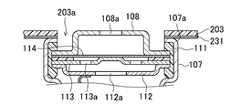
- FIG. 5is an enlarged partial cross-sectional view of the vicinity of one end of the unit cell 100 in which the partition wall 203 is disposed.
- a sheet-like elastic member 231such as silicone is bonded to the lower surface of the partition wall 203, and the protruding portion of the terminal plate 108 is inserted into the opening 203 a of the partition wall 203.
- the elastic member 231seals between the upper portion of the shoulder 107 a of the battery case 107 and the partition wall 203.
- the partition wall 203is a non-breathable partition wall. Therefore, the combustible gas discharged from the open portion 108 a provided on the protruding portion of the terminal plate 108 does not return to the battery chamber 201 again through the partition wall 203.
- the partition wall 203does not move the combustible gas discharged into the exhaust chamber 202 to the battery chamber 201, but the inert fluid introduced into the exhaust chamber 202 is movable to the battery chamber 201 via the partition wall 203.
- the bodyis desirable.
- Such a partition wall 203is configured by, for example, laminating a porous gas separation membrane that does not transmit a combustible gas but transmits an inert fluid.
- a combustible gasis generated in the exhaust chamber 202 when an abnormality occurs in the battery module 800 due to ignition of the flammable electrolyte and the safety valve mechanism of the unit cell 100 is opened.
- this combustible gasaccumulates in the exhaust chamber 202 and its pressure rises, and the pressure detected by the pressure sensor 150 becomes higher than a predetermined set pressure, the inert fluid supply control means 151 operates the actuator 144.
- the on-off valve 143is opened.
- the partition wall 203is the wall body described above, the combustible gas discharged into the exhaust chamber 202 does not move to the battery chamber 201, but the inert fluid introduced into the exhaust chamber 202 is indicated by an arrow 173. Thus, it can move to the battery chamber 201 through the partition wall 203. Therefore, the inert fluid can act on the unit cell 100 in which an abnormality has occurred, and as a result, the risk of firing or firing of the battery can be further reduced.
- the present inventionis the battery module 800.
- a battery pack in which a plurality of the battery modules 800 are combined by at least one of serial connection and parallel connectionmay be used.
- only one tank 141 in which an inert fluid is storedis installed in a plurality of battery modules 800, and the tank 141 is connected to each fluid inlet 120 of each battery module 800.
- the guide path 142has a branched structure.
- the occurrence of battery abnormalityis a very rare exceptional phenomenon. For this reason, providing a tank 141 for storing an inert fluid for each battery module increases the number of parts and is uneconomical.
- the unit cell 100is a lithium ion secondary battery, but the scope of the present invention is not limited to this, and for example, any battery that can be charged, such as a nickel metal hydride battery or a nickel cadmium battery. A battery can be used.
- the present inventioncan be used as a battery module that requires high capacity and high voltage, such as a hybrid vehicle or an electric vehicle, and that requires high reliability and safety.
Landscapes
- Chemical & Material Sciences (AREA)
- Chemical Kinetics & Catalysis (AREA)
- Electrochemistry (AREA)
- General Chemical & Material Sciences (AREA)
- Engineering & Computer Science (AREA)
- Manufacturing & Machinery (AREA)
- Materials Engineering (AREA)
- Battery Mounting, Suspending (AREA)
Abstract
Description
Translated fromJapanese本発明は、電気自動車等に用いられる電池モジュール及び電池パックに関し、特に、リチウムイオン電池等に代表される非水電解液を用いた二次電池を収容した電池モジュール及び複数の電池モジュールを電気的に接続した電池パックに関する。The present invention relates to a battery module and a battery pack used for an electric vehicle or the like, and more particularly, to electrically connect a battery module containing a secondary battery using a non-aqueous electrolyte typified by a lithium ion battery or the like and a plurality of battery modules. The battery pack connected to.
近年、非水系二次電池、特にリチウムイオン二次電池は、軽量でありながら、起電力が高く、高エネルギー密度であるという特長を有しているため、携帯電話やデジタルカメラ、ビデオカメラ、ノート型パソコン等の様々な種類の携帯型電子機器や移動体通信機器の駆動用電源としての需要が拡大している。In recent years, non-aqueous secondary batteries, in particular lithium ion secondary batteries, have features such as light weight, high electromotive force, and high energy density. Therefore, mobile phones, digital cameras, video cameras, notebooks, etc. As a power source for driving various types of portable electronic devices such as personal computers and mobile communication devices, demand is increasing.
一方、化石燃料の使用量の低減やCO2の排出量を削減するために、自動車等のモータ駆動用の電源として、組み合わせにより所望の電圧や容量を得ることができる電池モジュールが開発されている。On the other hand, in order to reduce the amount of fossil fuel used and the amount of CO2 emission, battery modules capable of obtaining desired voltages and capacities by combination have been developed as power sources for driving motors of automobiles and the like. .
この電池モジュールは、自動車の衝突等の異常時に対する安全性を高める必要があり、例えば特許文献1に示されるように、異常時には電池の発煙や引火を防ぐために、消火剤等の不活性流体を素電池に噴射するようになっている。This battery module needs to improve safety against abnormal situations such as automobile collision. For example, as shown in Patent Document 1, an inert fluid such as a fire extinguisher is used in order to prevent battery smoke and ignition when abnormal. It is designed to be injected into the unit cell.
ところで、例えば特許文献2には、消火剤を収容した密閉容器を、電池モジュールを収容したチャンバ内に設置し、異常発生時にその密閉容器が破壊されて、素電池に対して消火剤が作用するものが記載されている。By the way, for example, in Patent Document 2, a sealed container containing a fire extinguisher is installed in a chamber containing a battery module, and when the abnormality occurs, the sealed container is destroyed and the fire extinguisher acts on the unit cell. Things are listed.
しかし、上述の特許文献2の技術では、特許文献1の技術よりも異常発生時に素電池から発生する燃焼性ガスの存在により不活性流体(消火剤)が素電池に作用しにくく、類焼又は発火の危険性が低減されにくいという問題点がある。However, in the technique of Patent Document 2 described above, the inert fluid (extinguishing agent) is less likely to act on the unit cell due to the presence of combustible gas generated from the unit cell when an abnormality occurs than in the technique of Patent Document 1, so There is a problem that it is difficult to reduce the risk.
本発明はかかる問題点に鑑みてなされたものであって、素電池の異常発生時に類焼又は発火の危険性を低減できる電池モジュール、及び、この電池モジュールを複数接続した電池パックを提供することを目的とする。The present invention has been made in view of such problems, and provides a battery module that can reduce the risk of firing or firing when an abnormality occurs in a unit cell, and a battery pack in which a plurality of the battery modules are connected. Objective.
本発明に係る電池モジュールは、複数個の素電池と、これら複数個の素電池を収容するチャンバを有する電池収容ケースと、前記電池収容ケースに開口され、素電池の異常発生時に不活性流体を前記チャンバ内に導入させるための流体導入口と、前記電池収容ケースに開口され、素電池の異常発生時に該素電池から発生する燃焼性ガスを前記チャンバ内から排出させるためのガス排出口と、を備えることを特徴とする。A battery module according to the present invention includes a plurality of unit cells, a battery storage case having a chamber for storing the plurality of unit cells, and an opening that opens to the battery storage case, and provides an inert fluid when an abnormality occurs in the unit cells. A fluid inlet for introducing into the chamber; a gas outlet for opening the battery housing case to discharge a combustible gas generated from the unit cell when an abnormality occurs in the unit cell; It is characterized by providing.
本発明に係る電池モジュールにおいては、素電池の異常発生時に流体導入口から不活性流体をチャンバ内に導入させて、該素電池から発生する燃焼性ガスをガス排出口から排出させる。In the battery module according to the present invention, when a unit cell abnormality occurs, an inert fluid is introduced into the chamber from the fluid inlet, and the combustible gas generated from the unit cell is discharged from the gas outlet.
本発明によれば、素電池からの燃焼性ガスを速やかにガス排出口から排出させるため、高温の燃焼性ガスの滞留による類焼や発火の危険性を低減させることができる。また、燃焼性ガスを速やかにガス排出口から排出させるから、不活性流体を的確に素電池に作用させることができ、その結果電池の類焼又は発火の危険性を低減させることができる。According to the present invention, since the combustible gas from the unit cell is quickly discharged from the gas discharge port, it is possible to reduce the risk of burning or ignition due to retention of high-temperature combustible gas. Further, since the combustible gas is quickly discharged from the gas discharge port, the inert fluid can be made to act on the unit cell accurately, and as a result, the risk of burning or firing the battery can be reduced.
以下、添付の図面を参照して本発明の実施形態について具体的に説明するが、当該実施形態は本発明の原理の理解を容易にするためのものであり、本発明の範囲は、下記の実施形態に限られるものではなく、当業者が以下の実施形態の構成を適宜置換した他の実施形態も、本発明の範囲に含まれる。Hereinafter, embodiments of the present invention will be specifically described with reference to the accompanying drawings. However, the embodiments are for facilitating understanding of the principle of the present invention, and the scope of the present invention is as follows. The present invention is not limited to the embodiments, and other embodiments in which those skilled in the art appropriately replace the configurations of the following embodiments are also included in the scope of the present invention.
(実施形態1)
図1は、本実施形態における電池モジュールに使用する素電池の構成を模式的に示した断面図である。本発明の電池モジュールに使用する素電池100は、例えば、図1に示すような、円筒形のリチウムイオン二次電池を採用することができる。このリチウムイオン二次電池は、内部短絡等の異常発生により電池内の圧力が上昇したとき、ガスを電池外に放出する安全弁機構を備えている。以下、図1を参照しながら、素電池100の具体的な構成を説明する。(Embodiment 1)
FIG. 1 is a cross-sectional view schematically showing a configuration of a unit cell used in the battery module in the present embodiment. As the
図1に示すように、素電池100においては、正極101と負極102とがセパレータ103を介して捲回された電極群104が、非水電解液とともに、電池ケース107に収容されている。電極群104の上下には、絶縁板109、110が配され、正極101は、正極リード105を介してフィルタ112に接合され、負極102は、負極リード106を介して負極端子を兼ねる電池ケース107の底部に接合されている。As shown in FIG. 1, in the
正極及び負極の表面には、それぞれ、正極活物質及び負極活物質を含むペーストが塗布されている。正極活物質としては、例えばLiMn2O4、LiCoO2、LiNiO3等、リチウムイオン電池に用いられる正極活物質の1種又は2種以上を特に限定することなく使用できる。負極活物質としては、例えばアモルファスカーボン、グラファイトカーボン等、リチウムイオン電池に用いられる負極活物質の1種又は2種以上を特に限定することなく使用できる。非水電解液としては、例えばエチレンカーボネート、プロピレンカーボネート、ブチレンカーボネート、ビニレンカーボネート、ジメチルカーボネート、ジエチルカーボネート、エチルメチルカーボネート等を使用することができる。A paste containing a positive electrode active material and a negative electrode active material is applied to the surfaces of the positive electrode and the negative electrode, respectively. As the positive electrode active material, for exampleLiMn 2 O 4, LiCoO 2, LiNiO 3 , etc., can be used without particular limitation one or more of the positive electrode active material used in lithium ion batteries. As the negative electrode active material, for example, one or more negative electrode active materials used in lithium ion batteries, such as amorphous carbon and graphite carbon, can be used without particular limitation. As the non-aqueous electrolyte, for example, ethylene carbonate, propylene carbonate, butylene carbonate, vinylene carbonate, dimethyl carbonate, diethyl carbonate, ethyl methyl carbonate and the like can be used.
フィルタ112は、インナーキャップ113に接続され、インナーキャップ113の突起部は、金属製の弁板114に接合されている。さらに、弁板114は、正極端子を兼ねる端子板108に接続されている。そして、端子板108、弁板114、インナーキャップ113、及びフィルタ112が一体となって、ガスケット111を介して、電池ケース107の開口部を封口している。The
素電池100に内部短絡等の異常が発生して、素電池100内の圧力が上昇すると、弁体114が端子板108に向かって膨れ、インナーキャップ113と弁体114との接合がはずれると、電流経路が遮断される。さらに素電池100内の圧力が上昇すると、弁体114が破断する。これによって、素電池100内に発生したガスは、フィルタ112の貫通孔112a、インナーキャップ113の貫通孔113a、弁体114の裂け目、そして、端子板108の開放部108aを介して、外部へ排出される。When an abnormality such as an internal short circuit occurs in the
なお、素電池100内に発生したガスを外部に排出する安全弁機構は、図1に示した構造に限定されず、他の構造のものであってもよい。例えば、例えば弾性体で弁体を弁座に押圧し、素電池100の内圧が設定圧力よりも高くなると、弁体が弁座から離れて開弁される構成を採用することができる。In addition, the safety valve mechanism that discharges the gas generated in the
図2は、本実施形態に係る電池モジュール800の概略を説明する図である。図2に示すように、電池モジュール800は、例えばポリカーボネート樹脂製の筺体形状の電池収容ケース200と、この電池収容ケース200内に収容される複数個の素電池100と、を有する。素電池100は、矢印171に示す一方向に並設され、互いに電気的に例えば並列に接続されている。各素電池100は、電池収容ケース200の底部210に形成したリブ211によって、規制された位置に固定されている。なお、各素電池100は電池保持枠によって一体に保持されることも可能である。FIG. 2 is a diagram for explaining the outline of the
電池収容ケース200の一方の壁面の上側には、電池の異常発生時に不活性流体を電池収容ケース200内に導入させるための流体導入口120が開口されている。この流体導入口120には導入弁121が設けられており、通常時には導入弁121は閉弁されていて、電池収容ケース200内を密閉状態に保持する。そして、後述する不活性流体供給手段140から不活性流体が噴射されるとき、導入弁121は開弁されて不活性流体が電池収容ケース200内に供給される。導入弁121は、例えば不活性流体供給手段140から噴射される不活性流体の動圧等で破壊される破壊弁である。A
電池収容ケース200の他方の壁面の上側には、電池の異常発生時に該電池から発生する燃焼性ガスを電池収容ケース200から排出させるためのガス排出口130が設けられている。電池収容ケース200において、ガス排出口130と流体導入口120とは、例えば水平方向に対向した位置に配置されている。ガス排出口130には導入弁121と同様の排出弁131が設けられており、通常時には排出弁131は閉弁されていて、電池収容ケース200内を密閉状態に保持する。On the upper side of the other wall surface of the
不活性流体供給手段140は、不活性流体が貯蔵されるタンク141と、タンク141内に貯蔵される不活性流体を流体導入口120に案内する案内路142と、案内路142の途中に設けられ案内路142を開閉する開閉弁143と、開閉弁143の開閉動作を行うアクチュエータ144とを備える。The inert
不活性流体は、不活性のガス、液体、又はゲルである。不活性流体は、特に限定されるものではないが、例えば、非反応性の窒素、ヘリウム、アルゴン、ネオン、クリプトン、キセノン、二酸化炭素等のガス、又は、パーフロオロケトン等の燃焼反応を終了若しくは火災の発生を防止させる消火剤である。不活性流体の中に粉末又は微粒子等の固体成分を含有することも可能であり、例えば、二酸化炭素の中に炭酸水素ナトリウム粉末を含有させることが可能である。炭酸水素ナトリウムは高温に加熱されると吸熱して、二酸化炭素と水蒸気を発生し、電池収容ケース200内の温度を下げるとともに、不活性雰囲気に保ち、火災の発生を防止して燃焼反応を終了させる。The inert fluid is an inert gas, liquid, or gel. The inert fluid is not particularly limited. For example, non-reactive gas such as nitrogen, helium, argon, neon, krypton, xenon, carbon dioxide, or combustion reaction such as perfluoroketone is terminated or A fire extinguisher that prevents fire. It is also possible to contain a solid component such as powder or fine particles in the inert fluid. For example, it is possible to contain sodium hydrogen carbonate powder in carbon dioxide. When sodium bicarbonate is heated to a high temperature, it absorbs heat, generating carbon dioxide and water vapor, lowering the temperature in the
電池収容ケース200の天井部には、電池収容ケース200の内圧を検出する圧力センサー150が設けられている。圧力センサー150には不活性流体供給制御手段151が接続されている。不活性流体供給制御手段151は、圧力センサー150の検出結果に基づき、電池収容ケース200内の内圧が所定の設定圧力よりも高い場合に、燃焼性ガスをガス排出口130から排出するように、アクチュエータ144を作動させることにより開閉弁143を開弁し、不活性流体をタンク141から電池収容ケース200内に噴射させる。A
次に上述の構成の電池モジュール800の作用について説明する。例えば電池モジュール800はハイブリッド型の自動車に搭載され、その自動車の衝突等により、可燃性の電解液が発火する等にて電池モジュール800に異常が発生したとする。電池モジュール800の異常により電池から燃焼性ガスが発生する。この燃焼性ガスが素電池を収容するチャンバ内に溜まり、そのチャンバ内の圧力が上昇する。電池収容ケース200内の圧力は圧力センサー150にて検知されており、所定の設定圧力よりも高くなった場合には、不活性流体供給制御手段151はアクチュエータ144を作動させて開閉弁143を開かせる。開閉弁143が開くことによりタンク141から不活性流体が流れ込み、不活性流体の動圧により導入弁121が破壊されて流体導入口120が開き、不活性流体は電池収容ケース200内に導入される。圧力センサー150にて電池収容ケース200内の圧力を検出するから、緊急時であっても自動的に迅速に不活性流体を作用させることができる。Next, the operation of the
そしてこのように電池収容ケース200の一方の壁面から導入された不活性流体の圧力により、矢印172に示すように電池から発生した燃焼性ガスは電池収容ケース200の他方の壁面に押しやられて、その流れの動圧によりガス排出口130の排出弁131が破壊され、燃焼性ガスはガス排出口130から排出される。同時に、ガス導入口120から導入された不活性流体は矢印173に示すように素電池100に作用する。このようにして、燃焼性ガスをガス排出口130から排出させると共に、不活性流体を電池収容ケース200内に充満させて素電池100に作用させることで、電池の異常発生時の類焼又は発火の危険性を低減させることができる。And, by the pressure of the inert fluid introduced from one wall surface of the
なお、上述の実施形態では、電池収容ケース200内に圧力センサー150を設けたが、本発明の範囲はこのような実施形態に限定されるものではなく、例えば、圧力センサー150の代わりに電池収容ケース200の温度を検出する温度センサーを設け、不活性流体供給制御手段151は、温度センサーの検出結果に基づき、電池収容ケース200内の温度が所定の設定温度よりも高い場合に、不活性流体を電池収容ケース200内に噴射させて、燃焼性ガスをガス排出口130から排出することも可能である。In the above-described embodiment, the
また、例えば、圧力センサー150の代わりに電池収容ケース200内の燃焼性ガスを検出するガスセンサーを設け、不活性流体供給制御手段151は、ガスセンサーの検出結果に基づき、電池収容ケース200内に燃焼性ガスが所定量以上検出された場合に、不活性流体を電池収容ケース200内に噴射させて、燃焼性ガスをガス排出口130から排出することも可能である。また、これら圧力センサー150、温度センサー、及びガスセンサーは各々単独で設けられても良いし、組み合わせて設けることも可能である。Further, for example, instead of the
(実施形態2)
上述の実施形態1においては、電池収容ケース200の内圧を検出する圧力センサー150が設けられており、電池収容ケース200内の内圧が所定の設定圧力よりも高い場合に、不活性流体供給制御手段151により不活性流体が電池収容ケース200内に自動的に噴射されるものであったが、実施形態2においては、図3に示すように、消火器を用いて手動により不活性流体を電池収容ケース200内に噴射させる場合を説明する。(Embodiment 2)
In the first embodiment described above, the
図3は、消火器500を使用して不活性流体を電池収容ケース200内に噴射させる電池モジュール800の概略を説明する図である。図3に示すように、消火剤を導入させる消火剤導入路122の一方の端部(下流側)は流体導入口120に接続されている。また、消火剤導入路122の他方の端部(上流側)には、消火器500の消火剤ノズル510を挿入するためのノズル挿入口123に接続されている。FIG. 3 is a diagram for explaining an outline of the
また、ガス排出口130には、燃焼性ガスを排出する排出路132の一方の端部が接続しており、その他方の端部には排気口133が設けられ、このようにガス排出口130は排気口133として延長した位置に配置されている。そして例えば電池モジュール800が自動車等に搭載された場合において、設計上の制約等から排気口133とノズル挿入口123とは近接した位置に設置されている。ノズル挿入口123には、消火器500の使用者にノズル挿入口123と排気口133との間を識別するための識別手段が付されている。この識別手段は、特に限定されるものではないが、色彩、形状又はこれらの組み合わせから識別性を有する手段を用いることができ、例えば蛍光色のステッカーや、ノズル挿入口123の場所を指し示す矢印形状の構造物等を用いることができる。The
次に上述の構成の電池モジュール800の作用について説明する。例えば電池モジュール800が搭載されている自動車の衝突等により、可燃性の電解液が発火する等にて電池モジュール800に異常が発生したとする。電池モジュール800の異常により電池から燃焼性ガスが発生する。自動車の使用者は例えば予め車内に設置されている消火器500を用い、その消火器500の消火剤ノズル510をノズル挿入口123に挿入する。この際、識別手段がノズル挿入口123に設けられているため、電池モジュール800に異常が発生する緊急時でも消火器500の使用者は、排気口133と間違えることなく的確にノズル挿入口123に消火器500の消火剤ノズル510を挿入することができる。その後は消火器500を作動させ、不活性流体は電池収容ケース200内に導入される。そして矢印172に示すように燃焼性ガスはガス排出口130側に押しやられ、不活性流体は矢印173に示すように素電池100に作用する。このようにして、燃焼性ガスをガス排出口130から排出させると共に、不活性流体を電池収容ケース200内に充満させて素電池100に作用させることで、電池の異常発生時の類焼又は発火の危険性を低減させることができる。Next, the operation of the
なお、上述の実施形態では、ノズル挿入口123に設けられる識別手段は、色彩、形状又はこれらの組み合わせから識別性を有する手段であったが、このような実施形態に限定されることはなく、例えばノズル挿入口123の口金構造を消火剤ノズル510とは嵌合可能であるが、排気口133の口金構造を消火剤ノズル510とは嵌合不可能とすることにより、消火器500の使用者にノズル挿入口123と排気口133との区別がつくようにすることも可能である。In the above-described embodiment, the identification unit provided in the
(実施形態3)
上述の実施形態1及び2においては、燃焼性ガスは電池収容ケース200内に排出されるものであったが、実施形態3においては、電池収容ケース200内に燃焼性ガスを排出させるための専用の排気室を設ける。(Embodiment 3)
In the first and second embodiments, the combustible gas is discharged into the
図4は、燃焼性ガスを排出させるための専用の排気室202を有する電池モジュール800の概略を説明する図である。図4に示すように、実施形態3では、電池収容ケース200は、複数の素電池100の一端側(本実施形態では、正極端子を兼ねる端子板108側)に配設された区画壁203にて、素電池100が収容される電池室201と、この電池室201に収容される素電池100の開放部108aから排出される燃焼性ガスを排出する排気室202とに区画されている。素電池100の開放部108aは、区画壁203に形成された開口部203aを介して排気室202に連通している。排気室202の一方の壁面には流体導入口120が設けられており、他方の壁面にはガス排出口130が設けられている。FIG. 4 is a diagram illustrating an outline of a
電池室201に配設される複数の素電池100は、燃焼性ガスを排気室202に排出するように既述の安全弁機構を備えている。即ち、図5は、区画壁203が配設された素電池100の一端部の近傍を拡大した部分断面図である。図5に示すように、区画壁203の下面には例えばシリコーン等のシート状の弾性部材231が接合されており、端子板108の突起部が、区画壁203の開口部203aに挿入された状態で、電池ケース107の肩部107aの上部と区画壁203との間が弾性部材231によりシールされている。The plurality of
区画壁203は非通気性の隔壁である。そのため、端子板108の突起部に設けられた開放部108aから排出された燃焼性ガスは、区画壁203を通って再び電池室201に戻ることはない。区画壁203は、排気室202に排出された燃焼性ガスを電池室201に移動させないが、排気室202に導入された不活性流体は該区画壁203を介して電池室201へ移動可能な壁体であることが望ましい。このような区画壁203は、例えば、燃焼性ガスは透過しないが不活性流体は透過する多孔質のガス分離膜を積層する等により構成される。The
次に上述の構成の電池モジュール800の作用について説明する。可燃性の電解液が発火する等にて電池モジュール800に異常が発生し、素電池100の安全弁機構が開弁することにより、排気室202内に燃焼性ガスが発生する。この燃焼性ガスが排気室202内に溜まってその圧力が上昇し、圧力センサー150にて検知された圧力が、所定の設定圧力よりも高くなると、不活性流体供給制御手段151はアクチュエータ144を作動させて開閉弁143を開かせる。開閉弁143が開くことによりタンク141から不活性流体が排気室202内に流れ込み、矢印172に示すように燃焼性ガスは押しやられてガス排出口130から排出される。燃焼性ガスが排気される専用の排気室202を設けているから、速やかに燃焼性ガスをガス排出口130から排出させることができ、これにより高温の燃焼性ガスの滞留による類焼や発火の危険性を低減させることができる。Next, the operation of the
ここで、区画壁203が前述した壁体である場合は、排気室202に排出された燃焼性ガスは電池室201に移動しないが、排気室202に導入された不活性流体は矢印173に示すように該区画壁203を介して電池室201へ移動可能である。そのため不活性流体は異常が発生している素電池100に作用可能となり、その結果電池の類焼又は発火の危険性を更に低減させることができる。Here, when the
(その他の実施形態)
上述の実施形態では、本発明は電池モジュール800であったが、この電池モジュール800を複数個、直列接続及び並列接続の少なくとも一方により組み合わせて構成した電池パックとすることも可能である。かかる場合は、複数個の電池モジュール800に対して不活性流体が貯蔵されるタンク141を1基のみ設置し、その1基のタンク141から各電池モジュール800の各流体導入口120に対して接続するように案内路142を分岐構造にすることが好ましい。電池の異常発生は極めて希な例外的現象であり、そのために各電池モジュールごとに不活性流体が貯蔵されるタンク141を設けたのでは部品点数が増大すると共に不経済だからである。(Other embodiments)
In the above-described embodiment, the present invention is the
また、上述の実施形態では、素電池100はリチウムイオン二次電池であったが、本発明の範囲はこれに限定されるものではなく、例えばニッケル水素電池やニッケルカドミウム電池等の充電できる全ての電池を使用することができる。Further, in the above-described embodiment, the
本発明は、例えばハイブリッド自動車や電気自動車等の高容量・高電圧が必要で且つ高い信頼性と安全性が要求される電池モジュールとして利用できる。The present invention can be used as a battery module that requires high capacity and high voltage, such as a hybrid vehicle or an electric vehicle, and that requires high reliability and safety.
100:素電池
101:正極
102:負極
103:セパレータ
104:電極群
105:正極リード
106:負極リード
107:電池ケース
108:端子板
109,110:絶縁板
111:ガスケット
112:フィルタ
113:インナーキャップ
114:弁体
120:流体導入口
121:導入弁
122:消火剤導入路
123:ノズル挿入口
130:ガス排出口
131:排出弁
140:不活性流体供給手段
141:タンク
142:案内路
143:開閉弁
144:アクチュエータ
150:圧力センサー
151:不活性流体供給制御手段
200:電池収容ケース
201:電池室
202:排気室
203:区画壁
203a:開口部
231:弾性部材
500:消火器
510:消火剤ノズル
800:電池モジュールDESCRIPTION OF SYMBOLS 100: Unit cell 101: Positive electrode 102: Negative electrode 103: Separator 104: Electrode group 105: Positive electrode lead 106: Negative electrode lead 107: Battery case 108: Terminal board 109,110: Insulation board 111: Gasket 112: Filter 113: Inner cap 114 : Valve body 120: Fluid inlet 121: Inlet valve 122: Fire extinguisher inlet path 123: Nozzle insertion port 130: Gas outlet 131: Drain valve 140: Inert fluid supply means 141: Tank 142: Guide path 143: On-off valve 144: Actuator 150: Pressure sensor 151: Inert fluid supply control means 200: Battery housing case 201: Battery chamber 202: Exhaust chamber 203:
Claims (9)
Translated fromJapaneseこれら複数個の素電池を収容するチャンバを有する電池収容ケースと、
前記電池収容ケースに開口され、素電池の異常発生時に不活性流体を前記チャンバ内に導入させるための流体導入口と、
前記電池収容ケースに開口され、素電池の異常発生時に該素電池から発生する燃焼性ガスを前記チャンバ内から排出させるためのガス排出口と、を備えることを特徴とする電池モジュール。A plurality of unit cells;
A battery housing case having a chamber for housing the plurality of unit cells;
A fluid introduction port that is opened in the battery housing case and allows an inert fluid to be introduced into the chamber when a unit cell abnormality occurs;
A battery module, comprising: a gas discharge port that is opened in the battery housing case and discharges combustible gas generated from the unit cell from the chamber when a unit cell abnormality occurs.
前記圧力センサーの検出結果に基づき、前記チャンバの内圧が所定の設定圧力よりも高い場合に、前記燃焼性ガスを前記ガス排出口から排出するように、不活性流体を前記流体導入口から前記チャンバ内に導入させる不活性流体供給制御手段と、を備えることを特徴とする請求項1に記載の電池モジュール。A pressure sensor for detecting the internal pressure of the chamber;
Based on the detection result of the pressure sensor, when the internal pressure of the chamber is higher than a predetermined set pressure, an inert fluid is discharged from the fluid inlet to the chamber so that the combustible gas is discharged from the gas outlet. The battery module according to claim 1, further comprising an inert fluid supply control unit that is introduced into the battery module.
前記温度センサーの検出結果に基づき、前記チャンバの温度が所定の設定温度よりも高い場合に、前記燃焼性ガスを前記ガス排出口から排出するように、不活性流体を前記流体導入口から前記チャンバ内に導入させる不活性流体供給制御手段と、を備えることを特徴とする請求項1又は2に記載の電池モジュール。A temperature sensor for detecting the temperature of the chamber;
Based on the detection result of the temperature sensor, when the temperature of the chamber is higher than a predetermined set temperature, the inert fluid is discharged from the fluid inlet to the chamber so that the combustible gas is discharged from the gas outlet. The battery module according to claim 1, further comprising an inert fluid supply control unit that is introduced into the battery module.
前記ガスセンサーの検出結果に基づき、前記チャンバ内に前記燃焼性ガスが所定量以上検出された場合に、前記燃焼性ガスを前記ガス排出口から排出するように、不活性流体を前記流体導入口から前記チャンバ内に導入させる不活性流体供給制御手段と、を備えることを特徴とする請求項1乃至3の何れか1項に記載の電池モジュール。A gas sensor for detecting the presence of the combustible gas in the chamber;
Based on the detection result of the gas sensor, an inert fluid is supplied to the fluid inlet so that the combustible gas is discharged from the gas outlet when a predetermined amount or more of the combustible gas is detected in the chamber. 4. The battery module according to claim 1, further comprising an inert fluid supply control unit that is introduced into the chamber.
前記チャンバは、前記複数個の素電池が収容される電池室と、この電池室に収容される素電池の前記安全弁機構から放出される燃焼性ガスを排出する排気室と、に区画壁によって区画されており、
前記流体導入口は、該排気室の所定の壁面に設けられており、
前記ガス排出口は、該所定の壁面とは異なる他の壁面に設けられていることを特徴とする請求項1乃至4の何れか1項に記載の電池モジュール。The unit cell is provided with a safety valve mechanism that releases the combustible gas generated when an abnormality occurs to the outside of the unit cell,
The chamber is partitioned by a partition wall into a battery chamber in which the plurality of unit cells are accommodated and an exhaust chamber for discharging a combustible gas discharged from the safety valve mechanism of the unit cells accommodated in the battery chamber. Has been
The fluid inlet is provided on a predetermined wall surface of the exhaust chamber,
5. The battery module according to claim 1, wherein the gas discharge port is provided on another wall surface different from the predetermined wall surface. 6.
前記消火剤を放出する消火器の消火剤ノズルを挿入するためのノズル挿入口を前記消火剤導入路の他方の端部に有することを特徴とする請求項6に記載の電池モジュール。One end is connected to the fluid introduction port, and includes a fire extinguishing agent introduction path for introducing the fire extinguishing agent into the fluid introduction port,
The battery module according to claim 6, further comprising a nozzle insertion port for inserting a fire extinguishing agent nozzle of the fire extinguisher that discharges the fire extinguishing agent at the other end of the fire extinguishing agent introduction path.
Applications Claiming Priority (2)
| Application Number | Priority Date | Filing Date | Title |
|---|---|---|---|
| JP2010169732 | 2010-07-28 | ||
| JP2010-169732 | 2010-07-28 |
Publications (1)
| Publication Number | Publication Date |
|---|---|
| WO2012014348A1true WO2012014348A1 (en) | 2012-02-02 |
Family
ID=45529586
Family Applications (1)
| Application Number | Title | Priority Date | Filing Date |
|---|---|---|---|
| PCT/JP2011/001411WO2012014348A1 (en) | 2010-07-28 | 2011-03-10 | Cell module and cell pack |
Country Status (1)
| Country | Link |
|---|---|
| WO (1) | WO2012014348A1 (en) |
Cited By (26)
| Publication number | Priority date | Publication date | Assignee | Title |
|---|---|---|---|---|
| JP2014033824A (en)* | 2012-08-09 | 2014-02-24 | Hochiki Corp | Fire-extinguishing system for electric vehicle |
| JP2014036780A (en)* | 2012-08-20 | 2014-02-27 | Hochiki Corp | Fire-extinguishing system for electric vehicle |
| JP2014082108A (en)* | 2012-10-17 | 2014-05-08 | Hochiki Corp | Power storage device |
| AT13658U1 (en)* | 2012-07-27 | 2014-05-15 | Avl List Gmbh | battery |
| EP2879202A2 (en)* | 2013-11-27 | 2015-06-03 | The Boeing Company | Methods of inerting lithium-containing batteries and associated containers |
| JP2016508771A (en)* | 2013-01-25 | 2016-03-24 | バーケット、ブライアン | Fire smoke containment fire extinguishing device |
| CN106058119A (en)* | 2015-04-17 | 2016-10-26 | 三星Sdi株式会社 | Battery pack |
| JP2017004959A (en)* | 2016-06-24 | 2017-01-05 | ホーチキ株式会社 | Power storage device |
| JP2019510341A (en)* | 2016-02-25 | 2019-04-11 | ビーワイディー カンパニー リミテッド | Single cell battery, battery module, power battery, and electric vehicle |
| CN109910618A (en)* | 2019-03-28 | 2019-06-21 | 重庆长安新能源汽车科技有限公司 | A kind of battery safety management method, apparatus and new-energy automobile |
| US10854866B2 (en) | 2019-04-08 | 2020-12-01 | H55 Sa | Power supply storage and fire management in electrically-driven aircraft |
| US20210104798A1 (en)* | 2018-12-27 | 2021-04-08 | Contemporary Amperex Technology Co., Limited | Battery box |
| US11059386B2 (en) | 2018-01-25 | 2021-07-13 | H55 Sa | Construction and operation of electric or hybrid aircraft |
| US11063323B2 (en) | 2019-01-23 | 2021-07-13 | H55 Sa | Battery module for electrically-driven aircraft |
| US11065979B1 (en) | 2017-04-05 | 2021-07-20 | H55 Sa | Aircraft monitoring system and method for electric or hybrid aircrafts |
| US11148819B2 (en) | 2019-01-23 | 2021-10-19 | H55 Sa | Battery module for electrically-driven aircraft |
| CN113557629A (en)* | 2019-03-13 | 2021-10-26 | 雷诺股份公司 | Housing for a battery and method for introducing a fire extinguishing fluid into such a housing |
| CN113991227A (en)* | 2021-11-19 | 2022-01-28 | 九环储能科技有限公司 | Energy storage monomer, energy storage cluster and energy storage device |
| CN113991226A (en)* | 2021-11-19 | 2022-01-28 | 九环储能科技有限公司 | Combined energy storage unit, energy storage cluster and energy storage device |
| WO2022056722A1 (en)* | 2020-09-16 | 2022-03-24 | 华为数字能源技术有限公司 | Battery cell, battery pack, system, and electric vehicle |
| US20220161077A1 (en)* | 2020-11-24 | 2022-05-26 | Audi Ag | Motor vehicle with optimized accessibility for extinguishing a battery fire |
| CN114883714A (en)* | 2021-02-05 | 2022-08-09 | 北京好风光储能技术有限公司 | High-capacity battery |
| CN115411436A (en)* | 2022-08-23 | 2022-11-29 | 中国电建集团福建省电力勘测设计院有限公司 | Cooling and fire-fighting integrated system applied to lithium battery cabinet |
| WO2023273568A1 (en)* | 2021-06-30 | 2023-01-05 | 中国第一汽车股份有限公司 | Upper box body assembly, battery assembly, and electric vehicle |
| CN116053698A (en)* | 2023-01-10 | 2023-05-02 | 华为数字能源技术有限公司 | An energy storage system and an electrical device |
| US12409756B2 (en) | 2017-04-05 | 2025-09-09 | H55 Sa | Aircraft monitoring system and method for electric or hybrid aircrafts |
Citations (6)
| Publication number | Priority date | Publication date | Assignee | Title |
|---|---|---|---|---|
| JPH07226232A (en)* | 1994-02-14 | 1995-08-22 | Sony Corp | Non-aqueous electrolyte secondary battery and power source device |
| JP2007027011A (en)* | 2005-07-20 | 2007-02-01 | Sanyo Electric Co Ltd | Power source device |
| JP2009207650A (en)* | 2008-03-04 | 2009-09-17 | Panasonic Corp | Electric power device, electronic device using the same, and power supply element inspection facility |
| JP2009238654A (en)* | 2008-03-28 | 2009-10-15 | Sanyo Electric Co Ltd | Battery device |
| JP2009289668A (en)* | 2008-05-30 | 2009-12-10 | Toyota Motor Corp | Power storage device and vehicle |
| JP2010153117A (en)* | 2008-12-24 | 2010-07-08 | Mitsubishi Heavy Ind Ltd | Battery module |
- 2011
- 2011-03-10WOPCT/JP2011/001411patent/WO2012014348A1/enactiveApplication Filing
Patent Citations (6)
| Publication number | Priority date | Publication date | Assignee | Title |
|---|---|---|---|---|
| JPH07226232A (en)* | 1994-02-14 | 1995-08-22 | Sony Corp | Non-aqueous electrolyte secondary battery and power source device |
| JP2007027011A (en)* | 2005-07-20 | 2007-02-01 | Sanyo Electric Co Ltd | Power source device |
| JP2009207650A (en)* | 2008-03-04 | 2009-09-17 | Panasonic Corp | Electric power device, electronic device using the same, and power supply element inspection facility |
| JP2009238654A (en)* | 2008-03-28 | 2009-10-15 | Sanyo Electric Co Ltd | Battery device |
| JP2009289668A (en)* | 2008-05-30 | 2009-12-10 | Toyota Motor Corp | Power storage device and vehicle |
| JP2010153117A (en)* | 2008-12-24 | 2010-07-08 | Mitsubishi Heavy Ind Ltd | Battery module |
Cited By (40)
| Publication number | Priority date | Publication date | Assignee | Title |
|---|---|---|---|---|
| AT13658U1 (en)* | 2012-07-27 | 2014-05-15 | Avl List Gmbh | battery |
| JP2014033824A (en)* | 2012-08-09 | 2014-02-24 | Hochiki Corp | Fire-extinguishing system for electric vehicle |
| JP2014036780A (en)* | 2012-08-20 | 2014-02-27 | Hochiki Corp | Fire-extinguishing system for electric vehicle |
| JP2014082108A (en)* | 2012-10-17 | 2014-05-08 | Hochiki Corp | Power storage device |
| JP2016508771A (en)* | 2013-01-25 | 2016-03-24 | バーケット、ブライアン | Fire smoke containment fire extinguishing device |
| JP2015111570A (en)* | 2013-11-27 | 2015-06-18 | ザ・ボーイング・カンパニーTheBoeing Company | Methods of inerting lithium-containing batteries and associated containers |
| US10374201B2 (en) | 2013-11-27 | 2019-08-06 | The Boeing Company | Methods of inerting lithium-containing batteries and associated containers |
| US11101522B2 (en) | 2013-11-27 | 2021-08-24 | The Boeing Company | Methods of inerting lithium-containing batteries and associated containers |
| EP2879202A2 (en)* | 2013-11-27 | 2015-06-03 | The Boeing Company | Methods of inerting lithium-containing batteries and associated containers |
| CN106058119A (en)* | 2015-04-17 | 2016-10-26 | 三星Sdi株式会社 | Battery pack |
| JP2019510341A (en)* | 2016-02-25 | 2019-04-11 | ビーワイディー カンパニー リミテッド | Single cell battery, battery module, power battery, and electric vehicle |
| JP2017004959A (en)* | 2016-06-24 | 2017-01-05 | ホーチキ株式会社 | Power storage device |
| US11065979B1 (en) | 2017-04-05 | 2021-07-20 | H55 Sa | Aircraft monitoring system and method for electric or hybrid aircrafts |
| US11697358B2 (en) | 2017-04-05 | 2023-07-11 | H55 Sa | Aircraft monitoring system and method for electric or hybrid aircrafts |
| US12409756B2 (en) | 2017-04-05 | 2025-09-09 | H55 Sa | Aircraft monitoring system and method for electric or hybrid aircrafts |
| US11059386B2 (en) | 2018-01-25 | 2021-07-13 | H55 Sa | Construction and operation of electric or hybrid aircraft |
| US11685290B2 (en) | 2018-01-25 | 2023-06-27 | H55 Sa | Construction and operation of electric or hybrid aircraft |
| US20210104798A1 (en)* | 2018-12-27 | 2021-04-08 | Contemporary Amperex Technology Co., Limited | Battery box |
| US11949114B2 (en)* | 2018-12-27 | 2024-04-02 | Contemporary Amperex Technology Co., Limited | Battery box |
| US11063323B2 (en) | 2019-01-23 | 2021-07-13 | H55 Sa | Battery module for electrically-driven aircraft |
| US11148819B2 (en) | 2019-01-23 | 2021-10-19 | H55 Sa | Battery module for electrically-driven aircraft |
| US11634231B2 (en) | 2019-01-23 | 2023-04-25 | H55 Sa | Battery module for electrically-driven aircraft |
| US11456511B2 (en) | 2019-01-23 | 2022-09-27 | H55 Sa | Battery module for electrically-driven aircraft |
| CN113557629A (en)* | 2019-03-13 | 2021-10-26 | 雷诺股份公司 | Housing for a battery and method for introducing a fire extinguishing fluid into such a housing |
| JP7723878B2 (en) | 2019-03-13 | 2025-08-15 | アンペア エス.ア.エス. | Housing for a battery and method for introducing fire-extinguishing fluid into such a housing |
| JP2022522831A (en)* | 2019-03-13 | 2022-04-20 | ルノー エス.ア.エス. | Battery housings, and how to introduce fire extinguishing fluid into such housings |
| CN109910618A (en)* | 2019-03-28 | 2019-06-21 | 重庆长安新能源汽车科技有限公司 | A kind of battery safety management method, apparatus and new-energy automobile |
| US10854866B2 (en) | 2019-04-08 | 2020-12-01 | H55 Sa | Power supply storage and fire management in electrically-driven aircraft |
| CN115668612A (en)* | 2020-09-16 | 2023-01-31 | 华为数字能源技术有限公司 | Battery core, battery pack, system and electric automobile |
| WO2022056722A1 (en)* | 2020-09-16 | 2022-03-24 | 华为数字能源技术有限公司 | Battery cell, battery pack, system, and electric vehicle |
| CN114604071A (en)* | 2020-11-24 | 2022-06-10 | 奥迪股份公司 | Motor vehicle with optimized proximity for suppressing a battery fire |
| US20220161077A1 (en)* | 2020-11-24 | 2022-05-26 | Audi Ag | Motor vehicle with optimized accessibility for extinguishing a battery fire |
| CN114883714A (en)* | 2021-02-05 | 2022-08-09 | 北京好风光储能技术有限公司 | High-capacity battery |
| CN114883714B (en)* | 2021-02-05 | 2023-11-14 | 好风光储能技术(成都)有限公司 | High-capacity battery |
| WO2023273568A1 (en)* | 2021-06-30 | 2023-01-05 | 中国第一汽车股份有限公司 | Upper box body assembly, battery assembly, and electric vehicle |
| CN113991226B (en)* | 2021-11-19 | 2025-03-14 | 九环储能科技有限公司 | Combined energy storage monomer, energy storage cluster and energy storage device |
| CN113991226A (en)* | 2021-11-19 | 2022-01-28 | 九环储能科技有限公司 | Combined energy storage unit, energy storage cluster and energy storage device |
| CN113991227A (en)* | 2021-11-19 | 2022-01-28 | 九环储能科技有限公司 | Energy storage monomer, energy storage cluster and energy storage device |
| CN115411436A (en)* | 2022-08-23 | 2022-11-29 | 中国电建集团福建省电力勘测设计院有限公司 | Cooling and fire-fighting integrated system applied to lithium battery cabinet |
| CN116053698A (en)* | 2023-01-10 | 2023-05-02 | 华为数字能源技术有限公司 | An energy storage system and an electrical device |
Similar Documents
| Publication | Publication Date | Title |
|---|---|---|
| WO2012014348A1 (en) | Cell module and cell pack | |
| KR102656955B1 (en) | Batteries and related devices, manufacturing methods and manufacturing equipment | |
| CN103931020B (en) | Battery | |
| KR102686170B1 (en) | Batteries and related devices, manufacturing methods and manufacturing equipment | |
| JP4900534B2 (en) | Battery module and battery module assembly using the same | |
| JP5507173B2 (en) | Battery module and battery pack using the same | |
| JP4815026B2 (en) | Battery module and battery pack using the same | |
| JP7536879B2 (en) | Housing, battery, electrical equipment, and battery manufacturing method | |
| JP4749513B2 (en) | Battery module and battery pack using the same | |
| US20240128556A1 (en) | Battery module and battery pack with improved safety | |
| WO2008044430A1 (en) | Battery pack and battery-mounted device | |
| JP2023522801A (en) | BATTERY CASE, BATTERY, POWER CONSUMING DEVICE, CASE MANUFACTURING METHOD AND APPARATUS | |
| JP2008117756A (en) | Battery pack and battery-equipped device | |
| WO2013001585A1 (en) | Battery module | |
| KR20190031835A (en) | Battery case, battery pack including the same, and vehicle including the same | |
| KR20100118394A (en) | Pouch-type secondary battery comprising a portion of non-sealing residue | |
| KR20220163202A (en) | Battery Pack, and Vehicle Including the Same | |
| KR102625181B1 (en) | Fire fighting devices, case assemblies, batteries, electrical devices and methods of manufacturing batteries | |
| US20230268608A1 (en) | Battery cell, battery, and electric apparatus | |
| WO2024016212A1 (en) | Battery and electric device | |
| JP2024536984A (en) | Battery pack, energy storage device including the battery pack, and automobile | |
| CN218939874U (en) | Batteries and electrical devices | |
| WO2024077789A1 (en) | Battery and electric device | |
| CN116438695B (en) | Battery, electrical device, method for preparing battery, and device for preparing battery | |
| WO2025000905A1 (en) | Battery cell, battery, and electric device |
Legal Events
| Date | Code | Title | Description |
|---|---|---|---|
| 121 | Ep: the epo has been informed by wipo that ep was designated in this application | Ref document number:11811955 Country of ref document:EP Kind code of ref document:A1 | |
| NENP | Non-entry into the national phase | Ref country code:DE | |
| 122 | Ep: pct application non-entry in european phase | Ref document number:11811955 Country of ref document:EP Kind code of ref document:A1 | |
| NENP | Non-entry into the national phase | Ref country code:JP |