WO2011125193A1 - Vehicle driving-support apparatus - Google Patents
Vehicle driving-support apparatusDownload PDFInfo
- Publication number
- WO2011125193A1 WO2011125193A1PCT/JP2010/056331JP2010056331WWO2011125193A1WO 2011125193 A1WO2011125193 A1WO 2011125193A1JP 2010056331 WJP2010056331 WJP 2010056331WWO 2011125193 A1WO2011125193 A1WO 2011125193A1
- Authority
- WO
- WIPO (PCT)
- Prior art keywords
- vehicle
- travel
- air resistance
- host vehicle
- resistance distribution
- Prior art date
- Legal status (The legal status is an assumption and is not a legal conclusion. Google has not performed a legal analysis and makes no representation as to the accuracy of the status listed.)
- Ceased
Links
Images


Classifications
- B—PERFORMING OPERATIONS; TRANSPORTING
- B60—VEHICLES IN GENERAL
- B60W—CONJOINT CONTROL OF VEHICLE SUB-UNITS OF DIFFERENT TYPE OR DIFFERENT FUNCTION; CONTROL SYSTEMS SPECIALLY ADAPTED FOR HYBRID VEHICLES; ROAD VEHICLE DRIVE CONTROL SYSTEMS FOR PURPOSES NOT RELATED TO THE CONTROL OF A PARTICULAR SUB-UNIT
- B60W30/00—Purposes of road vehicle drive control systems not related to the control of a particular sub-unit, e.g. of systems using conjoint control of vehicle sub-units
- B60W30/10—Path keeping
- B60W30/12—Lane keeping
- B—PERFORMING OPERATIONS; TRANSPORTING
- B60—VEHICLES IN GENERAL
- B60W—CONJOINT CONTROL OF VEHICLE SUB-UNITS OF DIFFERENT TYPE OR DIFFERENT FUNCTION; CONTROL SYSTEMS SPECIALLY ADAPTED FOR HYBRID VEHICLES; ROAD VEHICLE DRIVE CONTROL SYSTEMS FOR PURPOSES NOT RELATED TO THE CONTROL OF A PARTICULAR SUB-UNIT
- B60W40/00—Estimation or calculation of non-directly measurable driving parameters for road vehicle drive control systems not related to the control of a particular sub unit, e.g. by using mathematical models
- B60W40/10—Estimation or calculation of non-directly measurable driving parameters for road vehicle drive control systems not related to the control of a particular sub unit, e.g. by using mathematical models related to vehicle motion
- B60W40/1005—Driving resistance
- G—PHYSICS
- G01—MEASURING; TESTING
- G01M—TESTING STATIC OR DYNAMIC BALANCE OF MACHINES OR STRUCTURES; TESTING OF STRUCTURES OR APPARATUS, NOT OTHERWISE PROVIDED FOR
- G01M9/00—Aerodynamic testing; Arrangements in or on wind tunnels
- G01M9/06—Measuring arrangements specially adapted for aerodynamic testing
- B—PERFORMING OPERATIONS; TRANSPORTING
- B60—VEHICLES IN GENERAL
- B60W—CONJOINT CONTROL OF VEHICLE SUB-UNITS OF DIFFERENT TYPE OR DIFFERENT FUNCTION; CONTROL SYSTEMS SPECIALLY ADAPTED FOR HYBRID VEHICLES; ROAD VEHICLE DRIVE CONTROL SYSTEMS FOR PURPOSES NOT RELATED TO THE CONTROL OF A PARTICULAR SUB-UNIT
- B60W2530/00—Input parameters relating to vehicle conditions or values, not covered by groups B60W2510/00 or B60W2520/00
- B60W2530/16—Driving resistance
- B—PERFORMING OPERATIONS; TRANSPORTING
- B60—VEHICLES IN GENERAL
- B60Y—INDEXING SCHEME RELATING TO ASPECTS CROSS-CUTTING VEHICLE TECHNOLOGY
- B60Y2400/00—Special features of vehicle units
- B60Y2400/92—Driver displays
Definitions
- the present inventionrelates to a vehicle travel support device that performs travel support of a vehicle.
- Patent Document 1a vehicle is organized according to the projected area of each vehicle in the direction of wind flow when the vehicle is running in a row.
- a row running systemthat reduces the energy consumption of the entire row.
- this row running systemwhen the row is one row, a vehicle having a relatively large projected area is disposed in front, and a vehicle having a relatively small projected area is disposed immediately behind the vehicle.
- An object of the present inventionis to provide a vehicle travel support device capable of effectively improving fuel consumption.
- the vehicle travel support apparatusincludes an air resistance distribution acquisition unit that acquires an air resistance distribution in the left-right direction of the host vehicle, and a target travel position determination that determines a target travel position of the host vehicle with respect to a preceding vehicle using the air resistance distribution. And travel support means for assisting the vehicle to guide the vehicle to a target travel position.
- the area immediately behind the preceding vehicleis the area where the aerodynamic effect is the largest.
- the area where the aerodynamic effect is the largestmay be shifted from right behind the preceding vehicle in the left-right direction due to, for example, the influence of crosswind.
- the vehicle travel support device of the present inventionthe lateral resistance distribution of the host vehicle is acquired, the target travel position of the host vehicle with respect to the preceding vehicle is determined using the air resistance distribution, and the vehicle is moved to the target travel position. Therefore, even if a region where a high aerodynamic effect is obtained by the preceding vehicle is shifted in the left-right direction of the host vehicle, the host vehicle can be guided to a position corresponding to the shift. For this reason, a fuel consumption can be improved effectively.
- the air resistance distribution acquisition meansfurther acquires the air resistance distribution in the front-rear direction of the host vehicle.
- the fuel efficiency in the front-rear directionis acquired in addition to the air resistance distribution in the left-right direction, and the target travel position is determined using the air resistance distribution, the fuel efficiency can be improved more effectively.
- the target travel position determining meansdetermines the target travel position according to the control performance of the behavior of the host vehicle in the left-right direction.
- the control performance of the behavior of the vehicle in the left-right directionvaries from vehicle to vehicle depending on various factors such as the response performance of the vehicle and the driving skill of the driver. Therefore, by determining the target travel position according to the control performance of the behavior in the left-right direction of the host vehicle, the host vehicle is guided to a position where fuel efficiency can be stably improved regardless of the control performance level. it can.
- the vehiclefurther includes environmental information acquisition means for acquiring environmental information around the host vehicle, and the target travel position determination means determines the target travel position based on the air resistance distribution and the environmental information.
- the vehiclefurther includes a travel risk detecting means for detecting a travel risk at each position around the host vehicle, and the target travel position determining means determines the target travel position so that the travel risk is minimized.
- the surrounding environmentby detecting the driving risk such as contact between the surrounding vehicle and the own vehicle or deviation of the own vehicle outside the driving lane, and determining the target driving position so that the driving risk is minimized. It is possible to achieve both driving of the host vehicle and improvement of fuel consumption.
- the travel risk detection meanscalculates a fuel efficiency improvement rate contour line at which the fuel efficiency improvement rate is constant at a predetermined target value based on the air resistance distribution, and the host vehicle at each position on the fuel efficiency improvement rate contour line Means for calculating the travel risk of the vehicle.
- the traveling of the host vehicle suitable for the surrounding environment and the improvement of fuel consumptioncan be surely achieved by simple arithmetic processing.
- FIG. 1is a block diagram showing a schematic configuration of a first embodiment of a vehicle travel support apparatus according to the present invention. It is a flowchart which shows the procedure of the vehicle travel assistance process performed by ECU shown by FIG. It is a figure which shows an example of a mode that the own vehicle is guide
- FIG. 1is a block diagram showing a schematic configuration of a first embodiment of a vehicle travel support apparatus according to the present invention.
- a vehicle travel support device 10 of the present embodimentis mounted on a vehicle, for example, and is a device that supports travel of the vehicle using a distribution of air resistance applied to the vehicle.
- a host vehiclea vehicle on which the vehicle travel support device 10 is mounted.
- the vehicle travel support device 10includes an air resistance detection unit 1, an environment information acquisition unit (environment information acquisition means) 2, an inter-vehicle distance detection unit 3, and an ECU (Electronic Control Unit) 4. It is equipped with.
- the air resistance detector 1detects air resistance applied to each part of the host vehicle.
- the air resistance detection unit 1includes, for example, a wind pressure sensor and a flow rate sensor installed in each part of the host vehicle, and detects air resistance applied to each part of the host vehicle using these sensors. Then, the air resistance detection unit 1 transmits the detection result to the ECU 4.
- the environmental information acquisition unit 2acquires environmental information around the host vehicle and transmits it to the ECU 4.
- the environmental informationincludes road information and weather information.
- the road informationis, for example, information indicating the position of a tunnel or a bridge existing on the road on which the host vehicle is traveling.
- the road informationis acquired using, for example, a navigation system (not shown).
- the meteorological informationis information indicating, for example, the wind speed, wind power, etc. for each season and time around the vehicle.
- the weather informationis acquired by, for example, radio broadcasting or AMeDAS of the Japan Meteorological Agency.
- the weather informationcan be corrected based on the past performance of the host vehicle traveling alone (without the preceding vehicle causing an aerodynamic effect). In this case, more reliable weather information can be obtained.
- the inter-vehicle distance detection unit 3includes an inter-vehicle distance sensor such as a millimeter wave radar, for example, and detects the inter-vehicle distance between the preceding vehicle and the host vehicle using the inter-vehicle distance sensor. Then, the inter-vehicle distance detection unit 3 transmits the detection result to the ECU 4.
- an inter-vehicle distance sensorsuch as a millimeter wave radar, for example
- the ECU 4is an electronic control unit including a CPU, a ROM, a RAM, an input / output port, and the like.
- the ECU 4functionally includes an air resistance distribution acquisition unit (air resistance distribution acquisition unit) 41, a control performance determination unit 42, a target travel position determination unit (target travel position determination unit) 43, and a travel support unit (travel). Support means) 44.
- the air resistance distribution acquisition unit 41acquires the air resistance distribution in the left-right direction and the front-rear direction of the host vehicle. Specifically, the air resistance distribution acquisition unit 41 is based on the detection results respectively detected by the air resistance detection unit 1 and the inter-vehicle distance detection unit 3, and the air resistance distribution in the left-right direction and the front-rear direction of the host vehicle at the current inter-vehicle distance. Is calculated. Then, the air resistance distribution acquisition unit 41 transmits information indicating the air resistance distribution to the target travel position determination unit 43.
- the control performance determination unit 42determines the control performance (described later) of the behavior of the host vehicle in the left-right direction. Then, the control performance determination unit 42 transmits the control performance determination result to the target travel position determination unit 43.
- the target travel position determination unit 43determines the target travel position of the host vehicle with respect to the preceding vehicle based on the air resistance distribution acquired by the air resistance distribution acquisition unit 41 and the environment information acquired by the environment information acquisition unit 2. Specifically, the target travel position determination unit 43 determines the target travel position according to the determination result of the control performance determined by the control performance determination unit 42 using the air resistance distribution and the environment information. Here, the target travel position is a position where air resistance applied to the host vehicle decreases. Then, the target travel position determination unit 43 transmits information indicating the target travel position to the travel support unit 44.
- the travel support unit 44provides support to guide the vehicle to the target travel position. Specifically, the travel support unit 44 presents the driver with information for prompting the driver to move the host vehicle to the target travel position on a screen display, or controls the host vehicle by controlling the handle torque or using an accelerator pedal with reaction force. To the target travel position.
- step S1based on the air resistance applied to each part of the host vehicle detected by the air resistance detector 1, an air resistance distribution in the left-right direction of the host vehicle is acquired (step S1).
- a position where the air resistance applied to the host vehicle decreasesis determined as a target travel position (step S2). For example, as shown in FIG. 3, when there is an influence of cross wind on the host vehicle, the position where the wind pressure is reduced becomes the target travel position. Then, as shown in FIG. 3, assistance is provided to guide the host vehicle to the target travel position determined in step S2 (step S3).
- step S4it is determined whether or not the air resistance distribution in the front-rear direction of the host vehicle can be acquired.
- step S4when it is determined that the air resistance distribution in the front-rear direction of the host vehicle cannot be acquired, the vehicle travel support process ends.
- step S4when it is determined in step S4 that the air resistance distribution in the front-rear direction of the host vehicle is acquirable, based on the air resistance applied to each part of the host vehicle detected by the air resistance detection unit 1, The air resistance distribution in the front-rear direction is acquired (step S5).
- step S6the control performance of the behavior of the own vehicle in the left-right direction is determined.
- the control performanceis determined based on the road recognition performance and response performance of the host vehicle, the rough road surface, and the like. Further, when the host vehicle is in the assist driving state, the control performance is determined based on the assist performance of the host vehicle. Further, when the host vehicle is in a manual driving state, the control performance is determined based on the driving skill of the driver.
- step S7a target travel position corresponding to the control performance determined in step S6 is determined (step S7).
- FIG. 4is a graph showing an example of an aerodynamic effect distribution obtained by the preceding vehicle.
- the horizontal axisindicates the position in the left-right direction of the host vehicle with the preceding vehicle as the origin, and the vertical axis indicates the magnitude of the aerodynamic effect obtained by the preceding vehicle.
- the solid lineindicates the distribution of aerodynamic effects when the inter-vehicle distance between the preceding vehicle and the own vehicle is relatively small, and the broken line indicates the inter-vehicle distance between the preceding vehicle and the own vehicle is relatively large. Shows the distribution of aerodynamic effects.
- FIG. 4 (a)shows the distribution of aerodynamic effects when there is no influence of crosswinds, etc.
- FIG. 4 (b)shows the distribution of aerodynamic effects changed by the influence of crosswinds
- FIG. The distribution of the aerodynamic effect changed by the influence of the tunnel wallis shown.
- the aerodynamic effect distribution by the preceding vehiclehas a relatively large maximum value and a relatively narrow distribution width.
- the aerodynamic effect distribution by the preceding vehiclehas a relatively small maximum value and a relatively wide distribution width.
- Assistis then provided to guide the vehicle to the target travel position determined in step S7 (step S8).
- the target travel positioncan be corrected in consideration of the environment information acquired by the environment information acquisition unit 2. For example, if the road information included in the environmental information indicates that the host vehicle is traveling in a tunnel, the target travel position can be corrected in consideration of changes in the airflow caused by the tunnel wall.
- the vehicle travel support apparatus 10acquires the air resistance distribution in the left-right direction and the front-rear direction of the host vehicle, and uses the air resistance distribution to target the travel position of the host vehicle with respect to the preceding vehicle. And assisting the vehicle to guide to the target travel position. For this reason, according to the vehicle travel support device 10, even if the region where a higher aerodynamic effect is obtained by the preceding vehicle is shifted in the left-right direction of the host vehicle, the host vehicle can be guided to a position corresponding to the shift. As a result, fuel efficiency can be improved effectively.
- the target travel position according to the control performance of the behavior in the left-right direction of the host vehicleis determined, so that the fuel consumption can be stably improved regardless of the level of the control performance.
- the vehiclecan be guided to a proper position.
- FIG. 5is a block diagram showing a schematic configuration of the second embodiment of the vehicle travel support apparatus according to the present invention.
- a vehicle travel support device 100 of this embodimentis mounted on a vehicle, for example, and is a device that supports travel of the vehicle using a distribution of air resistance applied to the vehicle.
- a vehicle on which the vehicle travel support device 100 is mountedis referred to as a host vehicle.
- the vehicle travel support device 100includes an air resistance detection unit 1, an environment information acquisition unit 2, a target fuel consumption acquisition unit 5, a surrounding monitoring information acquisition unit 6, and an ECU 7. Yes.
- the air resistance detection unit 1detects the air resistance applied to each part of the host vehicle, and transmits the detection result to the ECU 7. Further, as described above, the environmental information acquisition unit 2 acquires environmental information around the host vehicle and transmits the environmental information to the ECU 7.
- the target fuel efficiency acquisition unit 5sets a target value (target fuel efficiency improvement rate) of the fuel efficiency improvement rate to be achieved by the vehicle travel support device 100.
- the target fuel efficiency improvement rateis set by the driver via a predetermined input device (not shown), for example. Then, the target fuel consumption acquisition unit 5 transmits information indicating the set target fuel consumption improvement rate to the ECU 7.
- the periphery monitoring information acquisition unit 6acquires the periphery monitoring information using, for example, a millimeter wave radar or a camera.
- the peripheral monitoring informationincludes, for example, information indicating the position of the preceding vehicle, the width of the road on which the host vehicle travels, the position of the host vehicle on the road, the position, direction, speed, and the like of the surrounding vehicle including the oncoming vehicle.
- the periphery monitoring information acquisition unit 6can acquire such periphery monitoring information by road-to-vehicle communication, vehicle-to-vehicle communication, or the like using, for example, a predetermined communication device (not shown). Then, the periphery monitoring information acquisition unit 6 transmits the periphery monitoring information to the ECU 7.
- the ECU 7is an electronic control unit including a CPU, a ROM, a RAM, an input / output port, and the like.
- the ECU 7functionally includes an air resistance distribution acquisition unit 41, a control performance determination unit 42, a target travel position determination unit 43, a travel risk detection unit (travel risk detection means) 45, a travel support unit 44, have.
- the air resistance distribution acquisition part 41acquires the air resistance distribution of the left-right direction and the front-back direction of the own vehicle based on the air resistance applied to each part of the own vehicle acquired by the air resistance detection part 1 as described above. Then, the air resistance distribution acquisition unit 41 transmits information indicating the air resistance distribution to the travel risk detection unit 45.
- the travel risk detection unit 45detects a travel risk at each position around the host vehicle based on the periphery monitoring information acquired by the periphery monitoring information acquisition unit 6. Then, the travel risk detection unit 45 transmits information indicating the travel risk to the target travel position determination unit 43. More specifically, the travel risk detection unit 45 includes a contour line calculation unit 51 and a travel risk calculation unit 52.
- the contour line calculation unit 51calculates a fuel efficiency improvement rate contour line at which the fuel efficiency improvement rate becomes constant at the target fuel efficiency improvement rate.
- the travel risk calculation unit 52calculates the travel risk of the host vehicle at each position on the contour line of the fuel efficiency improvement rate.
- the travel riskincludes, for example, the risk of contact between the preceding vehicle, the oncoming vehicle, other surrounding vehicles, and the own vehicle, and the risk of departure of the own vehicle outside the travel lane.
- Driving risk⁇ 1 f (w) + ⁇ 2 g (x) + ⁇ 3 h (y) + ⁇ 4 k (z)
- wis the distance between the preceding vehicle and the own vehicle
- xis the distance between the oncoming vehicle and the own vehicle
- yis the distance between the surrounding vehicle other than the preceding vehicle and the oncoming vehicle
- zIs the distance until the vehicle departs from the driving lane.
- F, g, h, and kare predetermined functions having w, x, y, and z as variables, respectively. Therefore, f (w) indicates the contact risk between the preceding vehicle and the own vehicle, g (x) indicates the contact risk between the oncoming vehicle and the own vehicle, and h (y) indicates the preceding vehicle and the oncoming vehicle. The contact risk between the surrounding vehicle other than the vehicle and the host vehicle is shown, and k (z) shows the risk of departure of the host vehicle from the driving lane.
- ⁇ 1 to ⁇ 4are parameters for weighting these risks.
- the target travel position determination unit 43determines the target travel position so that the travel risk calculated as described above is minimized. Specifically, the target travel position determination unit 43 determines, as the target travel position, a position where the travel risk is minimized among the positions on the contour line of the fuel efficiency improvement rate.
- target travel position determination unit 43may determine the target travel position in consideration of the control performance of the behavior of the host vehicle in the left-right direction determined by the control performance determination unit 42.
- step S11the air resistance distribution in the left-right direction and the front-rear direction of the host vehicle is acquired based on the air resistance applied to each part of the host vehicle detected by the air resistance detector 1 (step S11).
- step S12the target fuel consumption improvement rate set by the target fuel consumption acquisition unit 5
- step S13the peripheral monitoring information acquired by the peripheral monitoring information acquisition unit 6 is input (step S13). Note that steps S11 to S13 may be executed in any order.
- a fuel efficiency improvement rate contour lineis calculated at which the fuel efficiency improvement rate becomes constant at the target fuel efficiency improvement rate set in step S12 (step S14).
- the fuel efficiency improvement rate contour calculated at this timeis, for example, a solid line indicated by a symbol S in FIG.
- the horizontal axis and the vertical axis in FIG. 7are coordinate axes with the preceding vehicle as the origin.
- step S15the travel risk of the host vehicle at each position on the contour line S of the fuel efficiency improvement rate calculated in step S14 is calculated (step S15).
- the position where the travel risk calculated in step S15 is minimizedis determined as the target travel position (step S16).
- the position where the contact risk f (w) between the preceding vehicle C 1 and the host vehicle C 0 is minimumis the preceding vehicle C. This is the position P at which the distance between the vehicle 1 and the host vehicle C 0 is maximum.
- the position Pis to become relatively close to the oncoming vehicle C 2, risk of contact with the oncoming vehicle C 2 and the vehicle C 0 g (x) is It becomes relatively large.
- the position where the travel risk is the minimumis the contact risk f (w) between the preceding vehicle C 1 and the host vehicle C 0 and the oncoming vehicle C.
- the contact risk g (x) between the vehicle 2 and the host vehicle C 0is a relatively small position Q.
- supportis provided so as to guide the host vehicle to the target travel position determined in step S16 (step S17).
- the target travel positioncan be determined in consideration of the environment information acquired by the environment information acquisition unit 2.
- the target travel positioncan be determined in consideration of the control performance of the behavior of the host vehicle in the left-right direction determined by the control performance determination unit 42.
- the vehicle travel support apparatus 100acquires the air resistance distribution in the left-right direction and the front-rear direction of the host vehicle, and calculates the fuel efficiency improvement rate contour line using the air resistance distribution. Then, the vehicle travel support apparatus 100 determines a position on the contour line of the fuel efficiency improvement rate as the target travel position, and performs support to guide the vehicle to the target travel position. For this reason, even if the area
- the vehicle travel support device 100calculates the travel risk at each position around the host vehicle and determines the position where the travel risk is minimum as the target travel position. At this time, the vehicle travel support apparatus 100 determines a position where the travel risk is minimum among the positions on the contour line of the fuel efficiency improvement rate as the target travel position. For this reason, according to the vehicle travel support device 100, it is possible to achieve both the travel of the host vehicle suitable for the surrounding environment and the improvement of fuel consumption.
- the present inventionis not limited to the above embodiment.
- the driverwhen providing assistance for guiding the host vehicle to the target travel position, if the target travel position deviates from the center of the travel lane, the driver may be uneasy about the guidance. For this reason, you may further provide HMI (Human Machine Interface) for obtaining from a driver the judgment whether the support for guiding the own vehicle to a target run position is performed.
- HMIHuman Machine Interface
- the HMIis preferably configured such that the driver can sensuously determine a position with a high aerodynamic effect by hearing, vision, and touch.
Landscapes
- Engineering & Computer Science (AREA)
- Physics & Mathematics (AREA)
- Automation & Control Theory (AREA)
- Transportation (AREA)
- Mechanical Engineering (AREA)
- Mathematical Physics (AREA)
- Fluid Mechanics (AREA)
- General Physics & Mathematics (AREA)
- Traffic Control Systems (AREA)
- Control Of Driving Devices And Active Controlling Of Vehicle (AREA)
Abstract
Description
Translated fromJapanese本発明は、車両の走行支援を行う車両走行支援装置に関するものである。The present invention relates to a vehicle travel support device that performs travel support of a vehicle.
従来、車両走行支援装置として、例えば特許文献1に記載されているように、複数の車両による隊列走行の際に、風の流れの方向についての各車両の投影面積に応じて隊列を編成することによって、隊列全体の消費エネルギーの低減を図る隊列走行システムが知られている。この隊列走行システムでは、隊列が一列である場合には、投影面積が相対的に大きい車両を前方に配置し、その真後ろに、投影面積が相対的に小さな車両を配置する。2. Description of the Related Art Conventionally, as described in Patent Document 1, for example, as described in Patent Document 1, a vehicle is organized according to the projected area of each vehicle in the direction of wind flow when the vehicle is running in a row. Thus, there is known a row running system that reduces the energy consumption of the entire row. In this row running system, when the row is one row, a vehicle having a relatively large projected area is disposed in front, and a vehicle having a relatively small projected area is disposed immediately behind the vehicle.
しかしながら、一列の隊列を編成して走行する場合においても、先行車両の真後ろが空力効果の最も大きい領域となるとは限らないため、上記の隊列走行システムでは、燃費向上が効果的に図れない場合がある。However, even when a single row of trains is organized and traveled, the rear side of the preceding vehicle is not necessarily the region where the aerodynamic effect is the greatest, so the above-mentioned platooning system may not effectively improve fuel efficiency. is there.
本発明の目的は、燃費を効果的に向上させることが可能な車両走行支援装置を提供することである。An object of the present invention is to provide a vehicle travel support device capable of effectively improving fuel consumption.
本発明の車両走行支援装置は、自車両の左右方向の空気抵抗分布を取得する空気抵抗分布取得手段と、空気抵抗分布を用いて先行車両に対する自車両の目標走行位置を決定する目標走行位置決定手段と、目標走行位置へ自車両を誘導するように支援を行う走行支援手段と、を備えることを特徴とするものである。The vehicle travel support apparatus according to the present invention includes an air resistance distribution acquisition unit that acquires an air resistance distribution in the left-right direction of the host vehicle, and a target travel position determination that determines a target travel position of the host vehicle with respect to a preceding vehicle using the air resistance distribution. And travel support means for assisting the vehicle to guide the vehicle to a target travel position.
一般に、先行車両の真後ろが空力効果の最も大きい領域であると考えられるが、例えば横風等の影響により、空力効果が最も大きい領域が先行車両の真後ろから左右方向にずれる場合がある。本発明の車両走行支援装置によれば、自車両の左右方向の空気抵抗分布を取得し、その空気抵抗分布を用いて先行車両に対する自車両の目標走行位置を決定し、その目標走行位置へ車両を誘導するように支援を行うので、先行車両により高い空力効果が得られる領域が自車両の左右方向にずれていても、そのずれに応じた位置へ自車両を誘導できる。このため、燃費を効果的に向上させることができる。Generally, it is considered that the area immediately behind the preceding vehicle is the area where the aerodynamic effect is the largest. However, the area where the aerodynamic effect is the largest may be shifted from right behind the preceding vehicle in the left-right direction due to, for example, the influence of crosswind. According to the vehicle travel support device of the present invention, the lateral resistance distribution of the host vehicle is acquired, the target travel position of the host vehicle with respect to the preceding vehicle is determined using the air resistance distribution, and the vehicle is moved to the target travel position. Therefore, even if a region where a high aerodynamic effect is obtained by the preceding vehicle is shifted in the left-right direction of the host vehicle, the host vehicle can be guided to a position corresponding to the shift. For this reason, a fuel consumption can be improved effectively.
好ましくは、空気抵抗分布取得手段は自車両の前後方向の空気抵抗分布をさらに取得する。Preferably, the air resistance distribution acquisition means further acquires the air resistance distribution in the front-rear direction of the host vehicle.
この場合、左右方向の空気抵抗分布に加えて前後方向の空気抵抗分布を取得し、その空気抵抗分布を用いて目標走行位置を決定するので、燃費を一層効果的に向上させることができる。In this case, since the air resistance distribution in the front-rear direction is acquired in addition to the air resistance distribution in the left-right direction, and the target travel position is determined using the air resistance distribution, the fuel efficiency can be improved more effectively.
このとき、好ましくは、目標走行位置決定手段は自車両の左右方向における挙動の制御性能に応じた目標走行位置を決定する。At this time, preferably, the target travel position determining means determines the target travel position according to the control performance of the behavior of the host vehicle in the left-right direction.
一般に、車両の左右方向における挙動の制御性能は、車両の応答性能やドライバーの運転技量等の種々の要因により、車両毎に異なる。このため、自車両の左右方向における挙動の制御性能に応じた目標走行位置を決定することにより、制御性能の高低に関わらず、安定して燃費を向上させることが可能な位置へ自車両を誘導できる。Generally, the control performance of the behavior of the vehicle in the left-right direction varies from vehicle to vehicle depending on various factors such as the response performance of the vehicle and the driving skill of the driver. Therefore, by determining the target travel position according to the control performance of the behavior in the left-right direction of the host vehicle, the host vehicle is guided to a position where fuel efficiency can be stably improved regardless of the control performance level. it can.
また、好ましくは、自車両の周辺の環境情報を取得する環境情報取得手段をさらに備え、目標走行位置決定手段は空気抵抗分布及び環境情報に基づいて目標走行位置を決定する。Preferably, the vehicle further includes environmental information acquisition means for acquiring environmental information around the host vehicle, and the target travel position determination means determines the target travel position based on the air resistance distribution and the environmental information.
この場合、自車両の周辺の環境情報を取得するので、自車両の周辺の環境に応じた目標走行位置を得ることができる。In this case, since environmental information around the host vehicle is acquired, a target travel position corresponding to the environment around the host vehicle can be obtained.
また、好ましくは、自車両の周辺の各位置における走行リスクを検出する走行リスク検出手段をさらに備え、目標走行位置決定手段は走行リスクが最小となるように目標走行位置を決定する。Preferably, the vehicle further includes a travel risk detecting means for detecting a travel risk at each position around the host vehicle, and the target travel position determining means determines the target travel position so that the travel risk is minimized.
例えば、周辺車両と自車両との接触や、走行車線外への自車両の逸脱といった走行リスクを検出し、走行リスクが最小となるように目標走行位置を決定することにより、周辺環境に適した自車両の走行と燃費の向上とを両立することができる。For example, it is suitable for the surrounding environment by detecting the driving risk such as contact between the surrounding vehicle and the own vehicle or deviation of the own vehicle outside the driving lane, and determining the target driving position so that the driving risk is minimized. It is possible to achieve both driving of the host vehicle and improvement of fuel consumption.
さらに、好ましくは、走行リスク検出手段は、空気抵抗分布に基づいて燃費向上率が所定の目標値で一定となる燃費向上率等高線を算出する手段と、燃費向上率等高線上の各位置における自車両の走行リスクを算出する手段と、を有する。Further preferably, the travel risk detection means calculates a fuel efficiency improvement rate contour line at which the fuel efficiency improvement rate is constant at a predetermined target value based on the air resistance distribution, and the host vehicle at each position on the fuel efficiency improvement rate contour line Means for calculating the travel risk of the vehicle.
この場合、周辺環境に適した自車両の走行と燃費の向上とを、簡単な演算処理により確実に両立することができる。In this case, the traveling of the host vehicle suitable for the surrounding environment and the improvement of fuel consumption can be surely achieved by simple arithmetic processing.
本発明によれば、燃費を効果的に向上させることが可能な車両走行支援装置を提供することができる。According to the present invention, it is possible to provide a vehicle travel support device that can effectively improve fuel efficiency.
以下、本発明に係わる車両走行支援装置の好適な実施形態について、図面を参照して詳細に説明する。なお、図面の説明において、可能な場合には、同一要素には同一符号を付し、重複する説明を省略する。Hereinafter, preferred embodiments of a vehicle travel support apparatus according to the present invention will be described in detail with reference to the drawings. In the description of the drawings, if possible, the same elements are denoted by the same reference numerals, and redundant description is omitted.
[第1実施形態]
図1は、本発明に係わる車両走行支援装置の第1実施形態の概略構成を示すブロック図である。同図において、本実施形態の車両走行支援装置10は、例えば車両に搭載されており、車両に加わる空気抵抗の分布を用いて当該車両の走行支援を行う装置である。なお、以下では、車両走行支援装置10が搭載された車両を自車両と称する。[First Embodiment]
FIG. 1 is a block diagram showing a schematic configuration of a first embodiment of a vehicle travel support apparatus according to the present invention. In the figure, a vehicle
図1に示されるように、車両走行支援装置10は、空気抵抗検出部1と、環境情報取得部(環境情報取得手段)2と、車間距離検出部3と、ECU(Electronic Control Unit)4と、を備えている。As shown in FIG. 1, the vehicle
空気抵抗検出部1は、自車両の各部に加わる空気抵抗を検出する。具体的に、空気抵抗検出部1は、例えば自車両の各部に設置された風圧センサや流量センサ等を有しており、これらのセンサを用いて自車両の各部に加わる空気抵抗を検出する。そして、空気抵抗検出部1は、検出結果をECU4へ送信する。The air resistance detector 1 detects air resistance applied to each part of the host vehicle. Specifically, the air resistance detection unit 1 includes, for example, a wind pressure sensor and a flow rate sensor installed in each part of the host vehicle, and detects air resistance applied to each part of the host vehicle using these sensors. Then, the air resistance detection unit 1 transmits the detection result to the
環境情報取得部2は、自車両の周辺の環境情報を取得してECU4へ送信する。環境情報は、道路情報と気象情報とを含む。道路情報は、例えば、自車両が走行する道路上に存在するトンネルや橋梁等の位置等を示す情報である。道路情報は、例えばナビゲーションシステム(不図示)等を用いて取得される。The environmental
気象情報は、例えば自車両の周辺における季節や時刻毎の風速や風力等を示す情報である。気象情報は、例えばラジオ放送や気象庁のアメダス等によって取得される。なお、気象情報は、自車両が単独で(空力効果を生じさせる先行車両なしで)走行した過去の実績に基づいて補正することができる。この場合、より確からしい気象情報が得られる。The meteorological information is information indicating, for example, the wind speed, wind power, etc. for each season and time around the vehicle. The weather information is acquired by, for example, radio broadcasting or AMeDAS of the Japan Meteorological Agency. The weather information can be corrected based on the past performance of the host vehicle traveling alone (without the preceding vehicle causing an aerodynamic effect). In this case, more reliable weather information can be obtained.
車間距離検出部3は、例えばミリ波レーダー等の車間距離センサを有しており、この車間距離センサを用いて先行車両と自車両との車間距離を検出する。そして、車間距離検出部3は、検出結果をECU4へ送信する。The inter-vehicle
ECU4は、CPU、ROM、RAMおよび入出力ポート等を備える電子制御ユニットである。ECU4は、機能的には、空気抵抗分布取得部(空気抵抗分布取得手段)41と、制御性能判定部42と、目標走行位置決定部(目標走行位置決定手段)43と、走行支援部(走行支援手段)44と、を有している。The
空気抵抗分布取得部41は、自車両の左右方向及び前後方向の空気抵抗分布を取得する。具体的に、空気抵抗分布取得部41は空気抵抗検出部1及び車間距離検出部3がそれぞれ検出した各検出結果に基づいて、現在の車間距離における自車両の左右方向及び前後方向の空気抵抗分布を算出する。そして、空気抵抗分布取得部41は、空気抵抗分布を示す情報を目標走行位置決定部43へ送信する。The air resistance
制御性能判定部42は、自車両の左右方向における挙動の制御性能(後述)を判定する。そして、制御性能判定部42は、制御性能の判定結果を目標走行位置決定部43へ送信する。The control
目標走行位置決定部43は、空気抵抗分布取得部41が取得した空気抵抗分布と環境情報取得部2が取得した環境情報とに基づいて、先行車両に対する自車両の目標走行位置を決定する。具体的に、目標走行位置決定部43は上記の空気抵抗分布と環境情報とを用いて、制御性能判定部42が判定した制御性能の判定結果に応じた目標走行位置を決定する。ここで、目標走行位置は、自車両に加わる空気抵抗が減少する位置である。そして、目標走行位置決定部43は、目標走行位置を示す情報を走行支援部44へ送信する。The target travel
走行支援部44は、目標走行位置へ自車両を誘導するように支援を行う。具体的に、走行支援部44は、例えば、目標走行位置への自車両の移動をドライバーに促すための情報を画面表示によりドライバーに提示したり、ハンドルトルクの制御や反力つきアクセルペダルにより自車両を目標走行位置へ誘導したりする。The
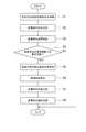
次に、図2を参照して、ECU4により実行される車両走行支援処理の手順について説明する。Next, with reference to FIG. 2, the procedure of the vehicle travel support process executed by the
同図において、まず、空気抵抗検出部1により検出された自車両の各部に加わる空気抵抗に基づいて、自車両の左右方向の空気抵抗分布を取得する(ステップS1)。In the figure, first, based on the air resistance applied to each part of the host vehicle detected by the air resistance detector 1, an air resistance distribution in the left-right direction of the host vehicle is acquired (step S1).
続いて、ステップS1で取得された空気抵抗分布を用いて、自車両に加わる空気抵抗が減少する位置を目標走行位置として決定する(ステップS2)。例えば、図3に示されるように、自車両に対して横風の影響があるときは、風圧が小さくなる位置が目標走行位置となる。そして、図3に示されるように、ステップS2で決定された目標走行位置へ自車両を誘導するように支援を行う(ステップS3)。Subsequently, using the air resistance distribution acquired in step S1, a position where the air resistance applied to the host vehicle decreases is determined as a target travel position (step S2). For example, as shown in FIG. 3, when there is an influence of cross wind on the host vehicle, the position where the wind pressure is reduced becomes the target travel position. Then, as shown in FIG. 3, assistance is provided to guide the host vehicle to the target travel position determined in step S2 (step S3).
続いて、自車両の前後方向の空気抵抗分布が取得可能であるか否かを判定する(ステップS4)。ステップS4において、自車両の前後方向の空気抵抗分布が取得できないと判定された場合、車両走行支援処理を終了する。Subsequently, it is determined whether or not the air resistance distribution in the front-rear direction of the host vehicle can be acquired (step S4). In step S4, when it is determined that the air resistance distribution in the front-rear direction of the host vehicle cannot be acquired, the vehicle travel support process ends.
一方、ステップS4において、自車両の前後方向の空気抵抗分布が取得可能であると判定された場合、空気抵抗検出部1により検出された自車両の各部に加わる空気抵抗に基づいて、自車両の前後方向の空気抵抗分布を取得する(ステップS5)。On the other hand, when it is determined in step S4 that the air resistance distribution in the front-rear direction of the host vehicle is acquirable, based on the air resistance applied to each part of the host vehicle detected by the air resistance detection unit 1, The air resistance distribution in the front-rear direction is acquired (step S5).
続いて、自車両の左右方向における挙動の制御性能を判定する(ステップS6)。このとき、自車両が自動運転の状態にある場合には、自車両の道路認識性能及び応答性能や、路面の荒れ状況等に基づいて制御性能を判定する。また、自車両がアシスト運転の状態にある場合は、自車両のアシスト性能等に基づいて制御性能を判定する。さらに、自車両がマニュアル運転の状態にある場合には、ドライバーの運転技量等に基づいて制御性能を判定する。Subsequently, the control performance of the behavior of the own vehicle in the left-right direction is determined (step S6). At this time, when the host vehicle is in an automatic driving state, the control performance is determined based on the road recognition performance and response performance of the host vehicle, the rough road surface, and the like. Further, when the host vehicle is in the assist driving state, the control performance is determined based on the assist performance of the host vehicle. Further, when the host vehicle is in a manual driving state, the control performance is determined based on the driving skill of the driver.
続いて、ステップS1及びステップS5で取得された空気抵抗分布に基づいて、ステップS6判定された制御性能に応じた目標走行位置を決定する(ステップS7)。Subsequently, based on the air resistance distribution acquired in step S1 and step S5, a target travel position corresponding to the control performance determined in step S6 is determined (step S7).
ここで、先行車両によって得られる空力効果の分布は、先行車両との車間距離に応じて異なる。図4は、先行車両によって得られる空力効果の分布の一例を示すグラフである。図4の各グラフにおいて、横軸は先行車両を原点とする自車両の左右方向の位置を示しており、縦軸は先行車両によって得られる空力効果の大きさを示している。また、図4の各グラフにおいて、実線は先行車両と自車両との車間距離が比較的小さい場合の空力効果の分布を示しており、破線は先行車両と自車両との車間距離が比較的大きい場合の空力効果の分布を示している。Here, the distribution of the aerodynamic effect obtained by the preceding vehicle differs depending on the distance between the preceding vehicle and the vehicle. FIG. 4 is a graph showing an example of an aerodynamic effect distribution obtained by the preceding vehicle. In each graph of FIG. 4, the horizontal axis indicates the position in the left-right direction of the host vehicle with the preceding vehicle as the origin, and the vertical axis indicates the magnitude of the aerodynamic effect obtained by the preceding vehicle. In each graph of FIG. 4, the solid line indicates the distribution of aerodynamic effects when the inter-vehicle distance between the preceding vehicle and the own vehicle is relatively small, and the broken line indicates the inter-vehicle distance between the preceding vehicle and the own vehicle is relatively large. Shows the distribution of aerodynamic effects.
図4(a)は横風等の影響が無い場合の空力効果の分布を示しており、図4(b)は横風の影響により変化した空力効果の分布を示しており、図4(c)はトンネルの壁面の影響により変化した空力効果の分布を示している。図4の各グラフに示されるように、先行車両と自車両との車間距離が比較的小さい場合、先行車両による空力効果の分布は、最大値が比較的大きく分布幅が比較的狭いものとなる。一方、先行車両と自車両との車間距離が比較的大きい場合、先行車両による空力効果の分布は、最大値が比較的小さく分布幅が比較的広いものとなる。FIG. 4 (a) shows the distribution of aerodynamic effects when there is no influence of crosswinds, etc., FIG. 4 (b) shows the distribution of aerodynamic effects changed by the influence of crosswinds, and FIG. The distribution of the aerodynamic effect changed by the influence of the tunnel wall is shown. As shown in each graph of FIG. 4, when the inter-vehicle distance between the preceding vehicle and the host vehicle is relatively small, the aerodynamic effect distribution by the preceding vehicle has a relatively large maximum value and a relatively narrow distribution width. . On the other hand, when the inter-vehicle distance between the preceding vehicle and the host vehicle is relatively large, the aerodynamic effect distribution by the preceding vehicle has a relatively small maximum value and a relatively wide distribution width.
このため、自車両の左右方向における挙動の制御性能が高い場合には、車間距離が比較的小さい位置を目標走行位置とすることにより、大きな空力効果が得られる。一方、自車両の左右方向における挙動の制御性能が低い場合には、車間距離が比較的大きい位置を目標走行位置とすることにより、安定した空力効果を得ることができる。For this reason, when the control performance of the behavior of the own vehicle in the left-right direction is high, a large aerodynamic effect can be obtained by setting the position where the inter-vehicle distance is relatively small as the target travel position. On the other hand, when the control performance of the behavior of the host vehicle in the left-right direction is low, a stable aerodynamic effect can be obtained by setting the position where the inter-vehicle distance is relatively large as the target travel position.
そして、ステップS7で決定された目標走行位置へ自車両を誘導するように支援を行う(ステップS8)。Assist is then provided to guide the vehicle to the target travel position determined in step S7 (step S8).
なお、ステップS2及びステップS7においては、環境情報取得部2により取得された環境情報を考慮して目標走行位置を補正することができる。例えば、環境情報に含まれる道路情報によって、自車両がトンネル中を走行していると認められる場合には、トンネルの壁面による気流の変化を考慮して目標走行位置を補正することができる。In step S2 and step S7, the target travel position can be corrected in consideration of the environment information acquired by the environment
以上説明したように、本実施形態に係わる車両走行支援装置10は、自車両の左右方向及び前後方向の空気抵抗分布を取得し、その空気抵抗分布を用いて先行車両に対する自車両の目標走行位置を決定し、その目標走行位置へ車両を誘導するように支援を行う。このため、車両走行支援装置10によれば、先行車両により高い空力効果が得られる領域が自車両の左右方向にずれていても、そのずれに応じた位置へ自車両を誘導できる。その結果、燃費を効果的に向上させることができる。As described above, the vehicle
また、車両走行支援装置10によれば、自車両の左右方向における挙動の制御性能に応じた目標走行位置を決定するので、制御性能の高低に関わらず、安定して燃費を向上させることが可能な位置へ自車両を誘導できる。Further, according to the vehicle
[第2実施形態]
図5は、本発明に係わる車両走行支援装置の第2実施形態の概略構成を示すブロック図である。同図において、本実施形態の車両走行支援装置100は、例えば車両に搭載されており、車両に加わる空気抵抗の分布を用いて当該車両の走行支援を行う装置である。なお、以下では、車両走行支援装置100が搭載された車両を自車両と称する。[Second Embodiment]
FIG. 5 is a block diagram showing a schematic configuration of the second embodiment of the vehicle travel support apparatus according to the present invention. In the figure, a vehicle
図5に示されるように、車両走行支援装置100は、空気抵抗検出部1と、環境情報取得部2と、目標燃費取得部5と、周辺監視情報取得部6と、ECU7と、を備えている。As shown in FIG. 5, the vehicle
空気抵抗検出部1は、上述したように、自車両の各部に加わる空気抵抗を検出して、検出結果をECU7へ送信する。また、環境情報取得部2は、上述したように、自車両の周辺の環境情報を取得してECU7へ送信する。As described above, the air resistance detection unit 1 detects the air resistance applied to each part of the host vehicle, and transmits the detection result to the
目標燃費取得部5は、車両走行支援装置100により達成すべき燃費向上率の目標値(目標燃費向上率)を設定する。目標燃費向上率は、例えば所定の入力装置(不図示)を介してドライバーにより設定される。そして、目標燃費取得部5は、設定された目標燃費向上率を示す情報をECU7に送信する。The target fuel
周辺監視情報取得部6は、例えばミリ波レーダーやカメラ等により、周辺監視情報を取得する。周辺監視情報は、例えば、先行車両の位置、自車両が走行する道路の幅、道路上における自車両の位置、及び、対向車両を含む周辺車両の位置や方位や速度等を示す情報を含む。周辺監視情報取得部6は、このような周辺監視情報を、例えば所定の通信装置(不図示)を用いて、路車間通信や車車間通信等により取得することができる。そして、周辺監視情報取得部6は、周辺監視情報をECU7へ送信する。The periphery monitoring
ECU7は、CPU、ROM、RAMおよび入出力ポートなどを備える電子制御ユニットである。ECU7は、機能的には、空気抵抗分布取得部41と、制御性能判定部42と、目標走行位置決定部43と、走行リスク検出部(走行リスク検出手段)45と、走行支援部44と、を有している。The
空気抵抗分布取得部41は、上述したように、空気抵抗検出部1が取得した自車両の各部に加わる空気抵抗に基づいて、自車両の左右方向及び前後方向の空気抵抗分布を取得する。そして、空気抵抗分布取得部41は、空気抵抗分布を示す情報を走行リスク検出部45へ送信する。The air resistance
走行リスク検出部45は、周辺監視情報取得部6が取得した周辺監視情報に基づいて、自車両の周辺の各位置における走行リスクを検出する。そして、走行リスク検出部45は、走行リスクを示す情報を目標走行位置決定部43へ送信する。より具体的には、走行リスク検出部45は、等高線算出部51と、走行リスク算出部52と、を含む。The travel
等高線算出部51は、空気抵抗分布取得部41が取得した空気抵抗分布に基づいて、燃費向上率が目標燃費向上率で一定となる燃費向上率等高線を算出する。走行リスク算出部52は、燃費向上率等高線上の各位置における自車両の走行リスクを算出する。なお、走行リスクは、例えば、先行車両や対向車両や他の周辺車両と自車両との接触リスクや、走行車線外への自車両の逸脱リスクを含む。このような走行リスクは、例えば下式によって算出することができる。
走行リスク=ε1f(w)+ε2g(x)+ε3h(y)+ε4k(z)Based on the air resistance distribution acquired by the air resistance
Driving risk = ε1 f (w) + ε2 g (x) + ε3 h (y) + ε4 k (z)
ここで、wは先行車両と自車両との距離であり、xは対向車両と自車両との距離であり、yは先行車両及び対向車両以外の周辺車両と自車両との距離であり、zは自車両が走行車線外に逸脱するまでの距離である。また、f、g、h及びkは、それぞれ、w、x、y及びzを変数とする所定の関数である。したがって、f(w)は先行車両と自車両との接触リスクを示しており、g(x)は対向車両と自車両との接触リスクを示しており、h(y)は先行車両及び対向車両以外の周辺車両と自車両との接触リスクを示しており、k(z)は自車両の走行車線外への逸脱リスクを示している。なお、ε1~ε4は、これらの各リスクの重み付けのためのパラメータである。Here, w is the distance between the preceding vehicle and the own vehicle, x is the distance between the oncoming vehicle and the own vehicle, y is the distance between the surrounding vehicle other than the preceding vehicle and the oncoming vehicle, and the own vehicle, z Is the distance until the vehicle departs from the driving lane. F, g, h, and k are predetermined functions having w, x, y, and z as variables, respectively. Therefore, f (w) indicates the contact risk between the preceding vehicle and the own vehicle, g (x) indicates the contact risk between the oncoming vehicle and the own vehicle, and h (y) indicates the preceding vehicle and the oncoming vehicle. The contact risk between the surrounding vehicle other than the vehicle and the host vehicle is shown, and k (z) shows the risk of departure of the host vehicle from the driving lane. Ε1 to ε4 are parameters for weighting these risks.
目標走行位置決定部43は、上記のようにして算出した走行リスクが最小となるように、目標走行位置を決定する。具体的には、目標走行位置決定部43は、燃費向上率等高線上の各位置のうち走行リスクが最小となる位置を、目標走行位置として決定する。The target travel
なお、目標走行位置決定部43は、制御性能判定部42が判定した自車両の左右方向における挙動の制御性能を考慮して、目標走行位置を決定してもよい。Note that the target travel
次に、図6を参照して、ECU7により実行される車両走行支援処理の手順について説明する。Next, with reference to FIG. 6, the procedure of the vehicle travel support process executed by the
同図において、まず、空気抵抗検出部1により検出された自車両の各部に加わる空気抵抗に基づいて、自車両の左右方向及び前後方向の空気抵抗分布を取得する(ステップS11)。続いて、目標燃費取得部5により設定された目標燃費向上率を入力する(ステップS12)。続いて、周辺監視情報取得部6により取得された周辺監視情報を入力する(ステップS13)なお、ステップS11~S13は、どのような順序で実行されてもよい。In the figure, first, the air resistance distribution in the left-right direction and the front-rear direction of the host vehicle is acquired based on the air resistance applied to each part of the host vehicle detected by the air resistance detector 1 (step S11). Subsequently, the target fuel consumption improvement rate set by the target fuel
続いて、ステップS11で取得された空気抵抗分布に基づいて、燃費の向上率が、ステップS12で設定された目標燃費向上率で一定となる燃費向上率等高線を算出する(ステップS14)。このとき算出される燃費向上率等高線は、例えば、図7において符号Sで示された実線のようになる。図7の横軸及び縦軸は、それぞれ、先行車両を原点とする座標軸である。Subsequently, based on the air resistance distribution acquired in step S11, a fuel efficiency improvement rate contour line is calculated at which the fuel efficiency improvement rate becomes constant at the target fuel efficiency improvement rate set in step S12 (step S14). The fuel efficiency improvement rate contour calculated at this time is, for example, a solid line indicated by a symbol S in FIG. The horizontal axis and the vertical axis in FIG. 7 are coordinate axes with the preceding vehicle as the origin.
続いて、ステップS14で算出された燃費向上率等高線S上の各位置における自車両の走行リスクを算出する(ステップS15)。Subsequently, the travel risk of the host vehicle at each position on the contour line S of the fuel efficiency improvement rate calculated in step S14 is calculated (step S15).
続いて、ステップS14で算出された燃費向上率等高線S上の各位置のうち、ステップS15で算出された走行リスクが最小となる位置を目標走行位置として決定する(ステップS16)。このとき、図7に示されるように、燃費向上率等高線S上の各位置のうち、先行車両C1と自車両C0との接触リスクf(w)が最小となる位置は、先行車両C1と自車両C0との距離が最大となる位置Pである。しかし、自車両の右側に対向車両C2が接近していると、位置Pは対向車両C2に比較的近くなるため、対向車両C2と自車両C0との接触リスクg(x)が比較的大きくなる。したがって、燃費向上率等高線S上の各位置のうち、走行リスクが最小となる位置(目標走行位置)は、先行車両C1と自車両C0との接触リスクf(w)と、対向車両C2と自車両C0との接触リスクg(x)と、が共に比較的小さくなる位置Qとなる。Subsequently, among the positions on the fuel efficiency improvement contour line S calculated in step S14, the position where the travel risk calculated in step S15 is minimized is determined as the target travel position (step S16). At this time, as shown in FIG. 7, among the positions on the fuel efficiency improvement contour line S, the position where the contact risk f (w) between the preceding vehicle C1 and the host vehicle C0 is minimum is the preceding vehicle C.This is the position P at which the distance between the vehicle1 and the host vehicle C0 is maximum. However, when the oncoming vehicle C2 on the right side of the vehicle is approaching, the position P is to become relatively close to the oncoming vehicle C2, risk of contact with the oncoming vehicle C2 and the vehicle C0 g (x) is It becomes relatively large. Accordingly, among the positions on the contour line S of the fuel efficiency improvement rate, the position where the travel risk is the minimum (target travel position) is the contact risk f (w) between the preceding vehicle C1 and the host vehicle C0 and the oncoming vehicle C. The contact risk g (x) between the vehicle2 and the host vehicle C0 is a relatively small position Q.
そして、ステップS16で決定された目標走行位置へ自車両を誘導するように支援を行う(ステップS17)。Then, support is provided so as to guide the host vehicle to the target travel position determined in step S16 (step S17).
なお、ステップS16においては、環境情報取得部2により取得される環境情報を考慮して目標走行位置を決定することができる。また、ステップ16においては、制御性能判定部42により判定される自車両の左右方向における挙動の制御性能をさらに考慮して目標走行位置を決定することができる。In step S16, the target travel position can be determined in consideration of the environment information acquired by the environment
以上説明したように、車両走行支援装置100は、自車両の左右方向及び前後方向の空気抵抗分布を取得し、その空気抵抗分布を用いて燃費向上率等高線を算出する。そして、車両走行支援装置100は、燃費向上率等高線上の位置を目標走行位置として決定し、その目標走行位置へ車両を誘導するように支援を行う。このため、先行車両により高い空力効果が得られる領域が自車両の左右方向にずれていても、そのずれに応じた位置へ自車両を誘導できる。このため、燃費を効果的に向上させることができる。As described above, the vehicle
また、車両走行支援装置100は、自車両の周辺の各位置における走行リスクを算出し、走行リスクが最小となる位置を目標走行位置として決定する。このとき、車両走行支援装置100は、燃費向上率等高線上の各位置のうち走行リスクが最小となる位置を、目標走行位置として決定する。このため、車両走行支援装置100によれば、周辺環境に適した自車両の走行と燃費の向上とを両立することができる。Also, the vehicle
なお、本発明は、上記実施形態に限定されるものではない。例えば、目標走行位置へ自車両を誘導するための支援を行う際に、目標走行位置が走行車線の中心からずれていると、当該誘導に対してドライバーが不安を抱く場合がある。このため、目標走行位置へ自車両を誘導するための支援を行うか否かの判断をドライバーから得るためのHMI(Human Machine Interface)をさらに備えてもよい。このHMIは、ドライバーが聴覚、視覚、触覚により感覚的に空力効果の高い位置を判断できるような構成とすることが好ましい。The present invention is not limited to the above embodiment. For example, when providing assistance for guiding the host vehicle to the target travel position, if the target travel position deviates from the center of the travel lane, the driver may be uneasy about the guidance. For this reason, you may further provide HMI (Human Machine Interface) for obtaining from a driver the judgment whether the support for guiding the own vehicle to a target run position is performed. The HMI is preferably configured such that the driver can sensuously determine a position with a high aerodynamic effect by hearing, vision, and touch.
燃費を効果的に向上させることが可能な車両走行支援装置を提供することができる。It is possible to provide a vehicle travel support device that can effectively improve fuel consumption.
2…環境情報取得部、4,7…ECU、41…空気抵抗分布取得部、42…制御性能判定部、43…目標走行位置決定部、44…走行支援部、45…走行リスク検出部、51…等高線算出部、52…走行リスク算出部。DESCRIPTION OF
Claims (6)
Translated fromJapanese前記空気抵抗分布を用いて先行車両に対する前記自車両の目標走行位置を決定する目標走行位置決定手段と、
前記目標走行位置へ前記自車両を誘導するように支援を行う走行支援手段と、
を備えることを特徴とする車両走行支援装置。Air resistance distribution acquisition means for acquiring the air resistance distribution in the left-right direction of the host vehicle;
Target travel position determining means for determining a target travel position of the host vehicle with respect to a preceding vehicle using the air resistance distribution;
Travel support means for assisting the vehicle to guide the target travel position;
A vehicle travel support apparatus comprising:
前記目標走行位置決定手段は前記空気抵抗分布及び前記環境情報に基づいて、前記目標走行位置を決定することを特徴とする請求項1~3の何れか一項に記載の車両走行支援装置。Further comprising environmental information acquisition means for acquiring environmental information around the host vehicle,
The vehicle travel support apparatus according to any one of claims 1 to 3, wherein the target travel position determination unit determines the target travel position based on the air resistance distribution and the environment information.
前記目標走行位置決定手段は前記走行リスクが最小となるように前記目標走行位置を決定することを特徴とする請求項1~4の何れか一項に記載の車両走行支援装置。A travel risk detection means for detecting a travel risk at each position around the host vehicle;
5. The vehicle travel support apparatus according to claim 1, wherein the target travel position determination unit determines the target travel position so that the travel risk is minimized.
The travel risk detecting means calculates a fuel efficiency improvement rate contour line at which a fuel efficiency improvement rate is constant at a predetermined target value based on the air resistance distribution; and the vehicle risk at each position on the fuel efficiency improvement rate contour line 6. The vehicle travel support apparatus according to claim 5, further comprising means for calculating a travel risk.
Priority Applications (5)
| Application Number | Priority Date | Filing Date | Title |
|---|---|---|---|
| DE112010005463TDE112010005463T5 (en) | 2010-04-07 | 2010-04-07 | Vehicle driving support device |
| US13/376,623US9145137B2 (en) | 2010-04-07 | 2010-04-07 | Vehicle driving-support apparatus |
| PCT/JP2010/056331WO2011125193A1 (en) | 2010-04-07 | 2010-04-07 | Vehicle driving-support apparatus |
| CN201080043635.XACN102548821B (en) | 2010-04-07 | 2010-04-07 | Vehicle Driving Assistance Device |
| JP2012509238AJP5141849B2 (en) | 2010-04-07 | 2010-04-07 | Vehicle travel support device |
Applications Claiming Priority (1)
| Application Number | Priority Date | Filing Date | Title |
|---|---|---|---|
| PCT/JP2010/056331WO2011125193A1 (en) | 2010-04-07 | 2010-04-07 | Vehicle driving-support apparatus |
Publications (1)
| Publication Number | Publication Date |
|---|---|
| WO2011125193A1true WO2011125193A1 (en) | 2011-10-13 |
Family
ID=44762179
Family Applications (1)
| Application Number | Title | Priority Date | Filing Date |
|---|---|---|---|
| PCT/JP2010/056331CeasedWO2011125193A1 (en) | 2010-04-07 | 2010-04-07 | Vehicle driving-support apparatus |
Country Status (5)
| Country | Link |
|---|---|
| US (1) | US9145137B2 (en) |
| JP (1) | JP5141849B2 (en) |
| CN (1) | CN102548821B (en) |
| DE (1) | DE112010005463T5 (en) |
| WO (1) | WO2011125193A1 (en) |
Cited By (20)
| Publication number | Priority date | Publication date | Assignee | Title |
|---|---|---|---|---|
| JP2013091401A (en)* | 2011-10-25 | 2013-05-16 | Isuzu Motors Ltd | Target traveling position-setting device, and steering control system |
| WO2013147682A1 (en) | 2012-03-27 | 2013-10-03 | Scania Cv Ab | Apparatus and method for enhancing fuel utilization during forward travel of a vehicle |
| US10042365B2 (en) | 2011-07-06 | 2018-08-07 | Peloton Technology, Inc. | Methods and systems for semi-autonomous vehicular convoys |
| US10078338B2 (en) | 2015-08-26 | 2018-09-18 | Peloton Technology, Inc. | Devices, systems, and methods for remote authorization of autonomous vehicle operation |
| US10152064B2 (en) | 2016-08-22 | 2018-12-11 | Peloton Technology, Inc. | Applications for using mass estimations for vehicles |
| US10254764B2 (en) | 2016-05-31 | 2019-04-09 | Peloton Technology, Inc. | Platoon controller state machine |
| US10369998B2 (en) | 2016-08-22 | 2019-08-06 | Peloton Technology, Inc. | Dynamic gap control for automated driving |
| US10474166B2 (en) | 2011-07-06 | 2019-11-12 | Peloton Technology, Inc. | System and method for implementing pre-cognition braking and/or avoiding or mitigation risks among platooning vehicles |
| US10481614B2 (en) | 2011-07-06 | 2019-11-19 | Peloton Technology, Inc. | Vehicle platooning systems and methods |
| US10514706B2 (en) | 2011-07-06 | 2019-12-24 | Peloton Technology, Inc. | Gap measurement for vehicle convoying |
| US10520581B2 (en) | 2011-07-06 | 2019-12-31 | Peloton Technology, Inc. | Sensor fusion for autonomous or partially autonomous vehicle control |
| US10520952B1 (en) | 2011-07-06 | 2019-12-31 | Peloton Technology, Inc. | Devices, systems, and methods for transmitting vehicle data |
| US10899323B2 (en) | 2018-07-08 | 2021-01-26 | Peloton Technology, Inc. | Devices, systems, and methods for vehicle braking |
| JP2021146998A (en)* | 2020-03-23 | 2021-09-27 | いすゞ自動車株式会社 | Rank traveling system |
| US11294396B2 (en) | 2013-03-15 | 2022-04-05 | Peloton Technology, Inc. | System and method for implementing pre-cognition braking and/or avoiding or mitigation risks among platooning vehicles |
| US11334092B2 (en) | 2011-07-06 | 2022-05-17 | Peloton Technology, Inc. | Devices, systems, and methods for transmitting vehicle data |
| US11341856B2 (en) | 2018-10-29 | 2022-05-24 | Peloton Technology, Inc. | Systems and methods for managing communications between vehicles |
| US11427196B2 (en) | 2019-04-15 | 2022-08-30 | Peloton Technology, Inc. | Systems and methods for managing tractor-trailers |
| WO2022196678A1 (en)* | 2021-03-19 | 2022-09-22 | いすゞ自動車株式会社 | Inter-vehicle distance determination device and inter-vehicle distance determination method |
| JP7666303B2 (en) | 2021-11-17 | 2025-04-22 | トヨタ自動車株式会社 | Control device |
Families Citing this family (22)
| Publication number | Priority date | Publication date | Assignee | Title |
|---|---|---|---|---|
| WO2014133425A1 (en)* | 2013-02-27 | 2014-09-04 | Volvo Truck Corporation | System and method for determining an aerodynamically favorable position between ground traveling vehicles |
| SE538848C2 (en) | 2015-03-06 | 2017-01-03 | Scania Cv Ab | Motor Vehicle for Inclusion in a Vehicle Train in which the Relative Lateral Vehicle Positions are Adjustable and corresponding Method |
| KR101860626B1 (en)* | 2016-01-07 | 2018-07-02 | 엘지전자 주식회사 | Driver Assistance Apparatus and Vehicle Having The Same |
| DE102016213039B4 (en)* | 2016-07-18 | 2022-11-17 | Cosmin Tudosie | Procedure for performing a convoy drive |
| WO2018038108A1 (en)* | 2016-08-26 | 2018-03-01 | 日本精工株式会社 | Control device for electric power steering device |
| DE102016011094A1 (en)* | 2016-09-15 | 2018-03-15 | Wabco Europe Bvba | Drag reducing device for a vehicle |
| US10059330B2 (en) | 2016-09-22 | 2018-08-28 | Toyota Motor Engineering & Manufacturing North America, Inc. | Drafting detection and vehicle operation optimization system |
| CN109109865B (en)* | 2017-06-23 | 2020-05-08 | 长城汽车股份有限公司 | Vehicle position detection method and device and vehicle |
| DE102017009306A1 (en)* | 2017-10-07 | 2019-04-11 | Wabco Gmbh | Method for arranging vehicles in a platoon and control arrangement for carrying out the method |
| JP6989429B2 (en)* | 2018-03-28 | 2022-01-05 | 株式会社東芝 | The platooning operation system and the platooning operation method |
| DE102018130968B4 (en) | 2018-12-05 | 2022-10-06 | Dr. Ing. H.C. F. Porsche Aktiengesellschaft | METHOD AND DEVICE FOR ADJUSTING AERODYNAMICS ON A MOVING VEHICLE |
| US11572068B2 (en) | 2020-10-07 | 2023-02-07 | Toyota Motor Engineering & Manufacturing North Amfrica, Inc. | Trailing vehicle positioning system based on detected lead vehicle |
| US11643080B2 (en) | 2020-10-07 | 2023-05-09 | Toyota Motor Engineering & Manufacturing North America, Inc. | Trailing vehicle positioning system based on detected pressure zones |
| CN113291293B (en)* | 2021-04-25 | 2022-05-06 | 宁波均联智行科技股份有限公司 | Method and system for controlling driving mode based on vehicle body stability |
| CN115257737B (en)* | 2022-07-19 | 2025-06-17 | 岚图汽车科技有限公司 | A vehicle following control method and related equipment |
| CN115195723A (en)* | 2022-07-19 | 2022-10-18 | 岚图汽车科技有限公司 | A vehicle-following control method and related equipment |
| CN115195725B (en)* | 2022-07-19 | 2025-07-29 | 岚图汽车科技有限公司 | Car following control method and related equipment |
| CN115195727B (en)* | 2022-07-19 | 2025-07-29 | 岚图汽车科技有限公司 | Car following control method and related equipment |
| CN115195724B (en)* | 2022-07-19 | 2025-03-18 | 岚图汽车科技有限公司 | A vehicle following control method and related equipment |
| CN115195726B (en)* | 2022-07-19 | 2025-04-15 | 岚图汽车科技有限公司 | A vehicle following control method and related equipment |
| DE102022207332A1 (en) | 2022-07-19 | 2024-01-25 | Volkswagen Aktiengesellschaft | Method for operating a driver assistance system, driver assistance system and motor vehicle with such a driver assistance system |
| CN115273448B (en)* | 2022-07-20 | 2023-11-10 | 岚图汽车科技有限公司 | Method for reducing aerodynamic resistance of front and rear vehicles and front and rear vehicle system |
Citations (4)
| Publication number | Priority date | Publication date | Assignee | Title |
|---|---|---|---|---|
| JP2005035349A (en)* | 2003-07-17 | 2005-02-10 | Toyota Motor Corp | Mobile body energy management apparatus and mobile body energy management method |
| JP2007283837A (en)* | 2006-04-13 | 2007-11-01 | Toyota Motor Corp | Vehicle driving support device |
| JP2008275500A (en)* | 2007-05-01 | 2008-11-13 | Toyota Motor Corp | Vehicular route guidance device |
| JP2009157790A (en)* | 2007-12-27 | 2009-07-16 | Equos Research Co Ltd | Convoy travel system |
Family Cites Families (63)
| Publication number | Priority date | Publication date | Assignee | Title |
|---|---|---|---|---|
| DE3816057C1 (en)* | 1988-05-11 | 1989-04-13 | Daimler-Benz Aktiengesellschaft, 7000 Stuttgart, De | |
| DE4127725A1 (en) | 1991-08-22 | 1993-02-25 | Porsche Ag | METHOD AND DEVICE FOR MINIMIZING THE SIDEWIND INFLUENCE ON THE DRIVING BEHAVIOR OF A VEHICLE |
| US5854987A (en)* | 1995-02-22 | 1998-12-29 | Honda Giken Kogyo Kabushiki Kaisha | Vehicle steering control system using navigation system |
| DE19519107C1 (en)* | 1995-05-24 | 1996-04-04 | Daimler Benz Ag | Travel route guidance device for electric vehicle |
| US5908217A (en)* | 1995-07-17 | 1999-06-01 | Georgia Tech Research Corporation | Pneumatic aerodynamic control and drag-reduction system for ground vehicles |
| JP3633707B2 (en)* | 1996-03-08 | 2005-03-30 | 日産ディーゼル工業株式会社 | Vehicle group running control device |
| JP3732292B2 (en)* | 1996-11-27 | 2006-01-05 | 本田技研工業株式会社 | Vehicle group running control system |
| JP3358709B2 (en)* | 1997-08-11 | 2002-12-24 | 富士重工業株式会社 | Driving support device for vehicles |
| US5926126A (en)* | 1997-09-08 | 1999-07-20 | Ford Global Technologies, Inc. | Method and system for detecting an in-path target obstacle in front of a vehicle |
| US6092021A (en)* | 1997-12-01 | 2000-07-18 | Freightliner Corporation | Fuel use efficiency system for a vehicle for assisting the driver to improve fuel economy |
| JP3651259B2 (en)* | 1998-05-01 | 2005-05-25 | 日産自動車株式会社 | Preceding vehicle tracking control device |
| US6269308B1 (en)* | 1998-08-20 | 2001-07-31 | Honda Giken Kogyo Kabushiki Kaisha | Safety running system for vehicle |
| DE10014328A1 (en)* | 1999-03-26 | 2000-09-28 | Denso Corp | Automatic travel regulation device for automobile e.g. for automatic movement in convoy, uses controlled acceleration or braking for maintaining required relative spacing between successive vehicles |
| JP3658519B2 (en)* | 1999-06-28 | 2005-06-08 | 株式会社日立製作所 | Vehicle control system and vehicle control device |
| JP4046905B2 (en)* | 1999-08-27 | 2008-02-13 | 本田技研工業株式会社 | Inter-vehicle distance measuring device |
| JP3174833B2 (en)* | 1999-10-27 | 2001-06-11 | 建設省土木研究所長 | Right turn collision prevention system |
| JP2001243600A (en)* | 2000-02-28 | 2001-09-07 | Hitachi Ltd | Vehicle travel control device |
| DE10030258A1 (en)* | 2000-06-20 | 2002-01-03 | Daimler Chrysler Ag | Method for controlling the distance of a vehicle from a preceding vehicle and distance control system |
| JP3681620B2 (en)* | 2000-07-26 | 2005-08-10 | 株式会社デンソー | Obstacle recognition device for vehicles |
| DE10047746A1 (en)* | 2000-09-27 | 2002-04-11 | Bayerische Motoren Werke Ag | Method for longitudinal control of a vehicle, in which information from a navigation system is recorded |
| US6894606B2 (en)* | 2000-11-22 | 2005-05-17 | Fred Forbes | Vehicular black box monitoring system |
| JP3844429B2 (en)* | 2000-12-12 | 2006-11-15 | 富士通テン株式会社 | Scanning radar equipment |
| JP3783562B2 (en)* | 2000-12-28 | 2006-06-07 | 日産自動車株式会社 | Vehicle travel control device |
| US20020152009A1 (en)* | 2001-04-11 | 2002-10-17 | Bartoli Fred J. | Method and apparatus for determining operational air quality and predicting vehicle performance |
| JP3788266B2 (en)* | 2001-05-11 | 2006-06-21 | 日産自動車株式会社 | Vehicle travel control device |
| JP2003042000A (en)* | 2001-07-27 | 2003-02-13 | Hanshin Electric Co Ltd | Fuel economy display device |
| JP3820984B2 (en)* | 2001-12-26 | 2006-09-13 | 日産自動車株式会社 | Lane departure prevention device |
| US6826479B2 (en)* | 2002-06-03 | 2004-11-30 | Visteon Global Technologies, Inc. | Method and apparatus for target vehicle identification in automatic cruise control and collision avoidance systems |
| US6927699B2 (en)* | 2002-12-05 | 2005-08-09 | Denso Corporation | Object recognition apparatus for vehicle, and inter-vehicle distance control unit |
| JP4578795B2 (en)* | 2003-03-26 | 2010-11-10 | 富士通テン株式会社 | Vehicle control device, vehicle control method, and vehicle control program |
| JP2004314849A (en)* | 2003-04-17 | 2004-11-11 | Nissan Motor Co Ltd | Travel control device |
| US7024306B2 (en)* | 2003-07-24 | 2006-04-04 | Miyama, Inc. | Evaluation system for vehicle operating conditions and evaluation method thereof |
| DE10361969A1 (en) | 2003-11-25 | 2005-06-30 | Ganter, Günther | Wind shadow measurement unit, especially for a bicycle, comprises a wind velocity meter and means for deriving a measurement value from its signal that is output to a display unit |
| JP4389567B2 (en)* | 2003-12-03 | 2009-12-24 | 日産自動車株式会社 | Lane departure prevention device |
| JP3982503B2 (en)* | 2004-01-21 | 2007-09-26 | 日産自動車株式会社 | Vehicle travel control device |
| JP2005263058A (en)* | 2004-03-19 | 2005-09-29 | Denso Corp | Vehicle travelling control device |
| US7109850B2 (en)* | 2004-03-29 | 2006-09-19 | Nissan Technical Center North America, Inc. | Rumble strip responsive systems |
| JP4176056B2 (en)* | 2004-06-24 | 2008-11-05 | 株式会社東芝 | Travel evaluation device, travel evaluation method, and travel evaluation program |
| US20060229793A1 (en)* | 2005-04-11 | 2006-10-12 | Honda Motor Co., Ltd. | Vehicular travel control system |
| JP4466571B2 (en)* | 2005-05-12 | 2010-05-26 | 株式会社デンソー | Driver status detection device, in-vehicle alarm device, driving support system |
| JP4396597B2 (en)* | 2005-08-08 | 2010-01-13 | 株式会社デンソー | Dangerous reaction point recording system and driving support system |
| US8370006B2 (en)* | 2006-03-20 | 2013-02-05 | General Electric Company | Method and apparatus for optimizing a train trip using signal information |
| US9201409B2 (en)* | 2006-03-20 | 2015-12-01 | General Electric Company | Fuel management system and method |
| JP2007261448A (en)* | 2006-03-29 | 2007-10-11 | Isuzu Motors Ltd | Vehicular air resistance reducing device |
| US8983765B2 (en)* | 2006-10-11 | 2015-03-17 | GM Global Technology Operations LLC | Method and system for lane centering control |
| JP4341665B2 (en)* | 2006-10-13 | 2009-10-07 | トヨタ自動車株式会社 | Vehicle steering control device |
| US7765058B2 (en)* | 2006-11-20 | 2010-07-27 | Ford Global Technologies, Llc | Driver input analysis and feedback system |
| JP2009166691A (en)* | 2008-01-16 | 2009-07-30 | Mazda Motor Corp | Vehicle traveling control device |
| JP2009248865A (en)* | 2008-04-09 | 2009-10-29 | Toyota Motor Corp | Vehicle group traveling controller |
| US8014928B2 (en) | 2008-06-17 | 2011-09-06 | Ford Global Technologies, Llc | Automotive slipstreaming support system |
| US20100020170A1 (en)* | 2008-07-24 | 2010-01-28 | Higgins-Luthman Michael J | Vehicle Imaging System |
| US8260515B2 (en)* | 2008-07-24 | 2012-09-04 | GM Global Technology Operations LLC | Adaptive vehicle control system with driving style recognition |
| US8280560B2 (en)* | 2008-07-24 | 2012-10-02 | GM Global Technology Operations LLC | Adaptive vehicle control system with driving style recognition based on headway distance |
| JP4602444B2 (en)* | 2008-09-03 | 2010-12-22 | 株式会社日立製作所 | Driver driving skill support apparatus and driver driving skill support method |
| JP4954173B2 (en)* | 2008-09-30 | 2012-06-13 | 本田技研工業株式会社 | Device for instructing the driver on driving operation to improve fuel efficiency |
| EP2390857B1 (en)* | 2009-01-20 | 2013-07-03 | Toyota Jidosha Kabushiki Kaisha | Row-running control system and vehicle |
| US20100209882A1 (en)* | 2009-02-18 | 2010-08-19 | Gm Global Technology Operations, Inc. | Driving skill recognition based on straight-line driving behavior |
| US8155868B1 (en)* | 2009-03-31 | 2012-04-10 | Toyota Infotechnology Center Co., Ltd. | Managing vehicle efficiency |
| US9165468B2 (en)* | 2010-04-12 | 2015-10-20 | Robert Bosch Gmbh | Video based intelligent vehicle control system |
| KR101294059B1 (en)* | 2011-07-28 | 2013-08-08 | 현대자동차주식회사 | Lane keep assistance system using in-wheel system |
| JP5652364B2 (en)* | 2011-09-24 | 2015-01-14 | 株式会社デンソー | Vehicle behavior control device |
| KR101316217B1 (en)* | 2011-09-28 | 2013-10-08 | 현대자동차주식회사 | Method and system for measured aerodynamic force information to improve mileage and driving stability for vehicle |
| US20130278441A1 (en)* | 2012-04-24 | 2013-10-24 | Zetta Research and Development, LLC - ForC Series | Vehicle proxying |
- 2010
- 2010-04-07WOPCT/JP2010/056331patent/WO2011125193A1/ennot_activeCeased
- 2010-04-07DEDE112010005463Tpatent/DE112010005463T5/ennot_activeWithdrawn
- 2010-04-07JPJP2012509238Apatent/JP5141849B2/ennot_activeExpired - Fee Related
- 2010-04-07USUS13/376,623patent/US9145137B2/ennot_activeExpired - Fee Related
- 2010-04-07CNCN201080043635.XApatent/CN102548821B/ennot_activeExpired - Fee Related
Patent Citations (4)
| Publication number | Priority date | Publication date | Assignee | Title |
|---|---|---|---|---|
| JP2005035349A (en)* | 2003-07-17 | 2005-02-10 | Toyota Motor Corp | Mobile body energy management apparatus and mobile body energy management method |
| JP2007283837A (en)* | 2006-04-13 | 2007-11-01 | Toyota Motor Corp | Vehicle driving support device |
| JP2008275500A (en)* | 2007-05-01 | 2008-11-13 | Toyota Motor Corp | Vehicular route guidance device |
| JP2009157790A (en)* | 2007-12-27 | 2009-07-16 | Equos Research Co Ltd | Convoy travel system |
Cited By (34)
| Publication number | Priority date | Publication date | Assignee | Title |
|---|---|---|---|---|
| US10520952B1 (en) | 2011-07-06 | 2019-12-31 | Peloton Technology, Inc. | Devices, systems, and methods for transmitting vehicle data |
| US10481614B2 (en) | 2011-07-06 | 2019-11-19 | Peloton Technology, Inc. | Vehicle platooning systems and methods |
| US10520581B2 (en) | 2011-07-06 | 2019-12-31 | Peloton Technology, Inc. | Sensor fusion for autonomous or partially autonomous vehicle control |
| US10042365B2 (en) | 2011-07-06 | 2018-08-07 | Peloton Technology, Inc. | Methods and systems for semi-autonomous vehicular convoys |
| US11360485B2 (en) | 2011-07-06 | 2022-06-14 | Peloton Technology, Inc. | Gap measurement for vehicle convoying |
| US11334092B2 (en) | 2011-07-06 | 2022-05-17 | Peloton Technology, Inc. | Devices, systems, and methods for transmitting vehicle data |
| US10162366B2 (en) | 2011-07-06 | 2018-12-25 | Peloton Technology, Inc. | Methods and systems for semi-autonomous vehicular convoys |
| US10216195B2 (en) | 2011-07-06 | 2019-02-26 | Peloton Technology, Inc. | Applications for using mass estimations for vehicles |
| US10234871B2 (en) | 2011-07-06 | 2019-03-19 | Peloton Technology, Inc. | Distributed safety monitors for automated vehicles |
| US10514706B2 (en) | 2011-07-06 | 2019-12-24 | Peloton Technology, Inc. | Gap measurement for vehicle convoying |
| US10732645B2 (en) | 2011-07-06 | 2020-08-04 | Peloton Technology, Inc. | Methods and systems for semi-autonomous vehicular convoys |
| US10281927B2 (en) | 2011-07-06 | 2019-05-07 | Peloton Technology, Inc. | Systems and methods for semi-autonomous vehicular convoys |
| US10474166B2 (en) | 2011-07-06 | 2019-11-12 | Peloton Technology, Inc. | System and method for implementing pre-cognition braking and/or avoiding or mitigation risks among platooning vehicles |
| JP2013091401A (en)* | 2011-10-25 | 2013-05-16 | Isuzu Motors Ltd | Target traveling position-setting device, and steering control system |
| EP2830919A4 (en)* | 2012-03-27 | 2016-10-19 | Scania Cv Ab | Apparatus and method for enhancing fuel utilization during forward travel of a vehicle |
| WO2013147682A1 (en) | 2012-03-27 | 2013-10-03 | Scania Cv Ab | Apparatus and method for enhancing fuel utilization during forward travel of a vehicle |
| US11294396B2 (en) | 2013-03-15 | 2022-04-05 | Peloton Technology, Inc. | System and method for implementing pre-cognition braking and/or avoiding or mitigation risks among platooning vehicles |
| US10712748B2 (en) | 2015-08-26 | 2020-07-14 | Peloton Technology, Inc. | Devices, systems, and methods for generating travel forecasts for vehicle pairing |
| US11100211B2 (en) | 2015-08-26 | 2021-08-24 | Peloton Technology, Inc. | Devices, systems, and methods for remote authorization of vehicle platooning |
| US10078338B2 (en) | 2015-08-26 | 2018-09-18 | Peloton Technology, Inc. | Devices, systems, and methods for remote authorization of autonomous vehicle operation |
| US10254764B2 (en) | 2016-05-31 | 2019-04-09 | Peloton Technology, Inc. | Platoon controller state machine |
| US10369998B2 (en) | 2016-08-22 | 2019-08-06 | Peloton Technology, Inc. | Dynamic gap control for automated driving |
| US10906544B2 (en) | 2016-08-22 | 2021-02-02 | Peloton Technology, Inc. | Dynamic gap control for automated driving |
| US10921822B2 (en) | 2016-08-22 | 2021-02-16 | Peloton Technology, Inc. | Automated vehicle control system architecture |
| US10152064B2 (en) | 2016-08-22 | 2018-12-11 | Peloton Technology, Inc. | Applications for using mass estimations for vehicles |
| US10899323B2 (en) | 2018-07-08 | 2021-01-26 | Peloton Technology, Inc. | Devices, systems, and methods for vehicle braking |
| US11341856B2 (en) | 2018-10-29 | 2022-05-24 | Peloton Technology, Inc. | Systems and methods for managing communications between vehicles |
| US11427196B2 (en) | 2019-04-15 | 2022-08-30 | Peloton Technology, Inc. | Systems and methods for managing tractor-trailers |
| JP2021146998A (en)* | 2020-03-23 | 2021-09-27 | いすゞ自動車株式会社 | Rank traveling system |
| JP7287321B2 (en) | 2020-03-23 | 2023-06-06 | いすゞ自動車株式会社 | platooning system |
| WO2022196678A1 (en)* | 2021-03-19 | 2022-09-22 | いすゞ自動車株式会社 | Inter-vehicle distance determination device and inter-vehicle distance determination method |
| JP2022144678A (en)* | 2021-03-19 | 2022-10-03 | いすゞ自動車株式会社 | Inter-vehicular distance determination device and inter-vehicular distance determination method |
| JP7359182B2 (en) | 2021-03-19 | 2023-10-11 | いすゞ自動車株式会社 | Inter-vehicle distance determination device and inter-vehicle distance determination method |
| JP7666303B2 (en) | 2021-11-17 | 2025-04-22 | トヨタ自動車株式会社 | Control device |
Also Published As
| Publication number | Publication date |
|---|---|
| CN102548821B (en) | 2016-01-20 |
| JPWO2011125193A1 (en) | 2013-07-08 |
| CN102548821A (en) | 2012-07-04 |
| US9145137B2 (en) | 2015-09-29 |
| DE112010005463T5 (en) | 2013-03-14 |
| US20130096773A1 (en) | 2013-04-18 |
| JP5141849B2 (en) | 2013-02-13 |
Similar Documents
| Publication | Publication Date | Title |
|---|---|---|
| JP5141849B2 (en) | Vehicle travel support device | |
| US10429848B2 (en) | Automatic driving system | |
| US9796416B2 (en) | Automated driving apparatus and automated driving system | |
| JP6596043B2 (en) | Vehicle travel control system | |
| US10019017B2 (en) | Autonomous driving system | |
| US9884645B2 (en) | Lane change control system | |
| JP6432679B2 (en) | Stop position setting apparatus and method | |
| RU2605812C2 (en) | Driving aid device and method of driving assistance | |
| US9108664B2 (en) | Control apparatus of vehicle for changing lane and control method of the same | |
| JP5765431B2 (en) | Vehicle driving support system | |
| CN107107751B (en) | Target vehicle speed generation device and travel control device | |
| JP6941178B2 (en) | Automatic operation control device and method | |
| JP2018063524A (en) | Vehicle controller | |
| JP2016172531A (en) | Vehicle control device | |
| CN102729996B (en) | method and device for operating a motor vehicle | |
| JP2016193683A (en) | Vehicle control device | |
| JP2017144769A (en) | Vehicle maintenance control device | |
| CN104334428A (en) | A lane-marking crossing warning system | |
| JP2017140857A (en) | Vehicle control system | |
| JP2010257307A (en) | Driving support system | |
| JP2008059366A (en) | Steering angle determination device, automobile and steering angle determination method | |
| CN202271993U (en) | Vehicle drive-assistant device | |
| WO2014042364A1 (en) | Vehicle motion integrated control type lane-keeping assistance system | |
| JP2019026100A (en) | Traveling control system of vehicle | |
| JP2005132194A (en) | Vehicle lane travel support device |
Legal Events
| Date | Code | Title | Description |
|---|---|---|---|
| WWE | Wipo information: entry into national phase | Ref document number:201080043635.X Country of ref document:CN | |
| WWE | Wipo information: entry into national phase | Ref document number:2012509238 Country of ref document:JP | |
| 121 | Ep: the epo has been informed by wipo that ep was designated in this application | Ref document number:10849437 Country of ref document:EP Kind code of ref document:A1 | |
| WWE | Wipo information: entry into national phase | Ref document number:13376623 Country of ref document:US | |
| WWE | Wipo information: entry into national phase | Ref document number:112010005463 Country of ref document:DE Ref document number:1120100054630 Country of ref document:DE | |
| 122 | Ep: pct application non-entry in european phase | Ref document number:10849437 Country of ref document:EP Kind code of ref document:A1 |