WO2011114537A1 - Transmission apparatus, fault recovery method, and network system - Google Patents
Transmission apparatus, fault recovery method, and network systemDownload PDFInfo
- Publication number
- WO2011114537A1 WO2011114537A1PCT/JP2010/054890JP2010054890WWO2011114537A1WO 2011114537 A1WO2011114537 A1WO 2011114537A1JP 2010054890 WJP2010054890 WJP 2010054890WWO 2011114537 A1WO2011114537 A1WO 2011114537A1
- Authority
- WO
- WIPO (PCT)
- Prior art keywords
- frame
- shared
- ring
- odu
- failure
- Prior art date
- Legal status (The legal status is an assumption and is not a legal conclusion. Google has not performed a legal analysis and makes no representation as to the accuracy of the status listed.)
- Ceased
Links
Images


Classifications
- H—ELECTRICITY
- H04—ELECTRIC COMMUNICATION TECHNIQUE
- H04L—TRANSMISSION OF DIGITAL INFORMATION, e.g. TELEGRAPHIC COMMUNICATION
- H04L12/00—Data switching networks
- H04L12/28—Data switching networks characterised by path configuration, e.g. LAN [Local Area Networks] or WAN [Wide Area Networks]
- H04L12/42—Loop networks
- H04L12/437—Ring fault isolation or reconfiguration
- H—ELECTRICITY
- H04—ELECTRIC COMMUNICATION TECHNIQUE
- H04B—TRANSMISSION
- H04B10/00—Transmission systems employing electromagnetic waves other than radio-waves, e.g. infrared, visible or ultraviolet light, or employing corpuscular radiation, e.g. quantum communication
- H04B10/25—Arrangements specific to fibre transmission
- H—ELECTRICITY
- H04—ELECTRIC COMMUNICATION TECHNIQUE
- H04B—TRANSMISSION
- H04B10/00—Transmission systems employing electromagnetic waves other than radio-waves, e.g. infrared, visible or ultraviolet light, or employing corpuscular radiation, e.g. quantum communication
- H04B10/27—Arrangements for networking
- H04B10/275—Ring-type networks
- H—ELECTRICITY
- H04—ELECTRIC COMMUNICATION TECHNIQUE
- H04L—TRANSMISSION OF DIGITAL INFORMATION, e.g. TELEGRAPHIC COMMUNICATION
- H04L12/00—Data switching networks
- H04L12/28—Data switching networks characterised by path configuration, e.g. LAN [Local Area Networks] or WAN [Wide Area Networks]
- H04L12/40—Bus networks
- H04L12/40006—Architecture of a communication node
- H04L12/40013—Details regarding a bus controller
- H—ELECTRICITY
- H04—ELECTRIC COMMUNICATION TECHNIQUE
- H04Q—SELECTING
- H04Q2213/00—Indexing scheme relating to selecting arrangements in general and for multiplex systems
- H04Q2213/1301—Optical transmission, optical switches
- H—ELECTRICITY
- H04—ELECTRIC COMMUNICATION TECHNIQUE
- H04Q—SELECTING
- H04Q2213/00—Indexing scheme relating to selecting arrangements in general and for multiplex systems
- H04Q2213/13166—Fault prevention
- H—ELECTRICITY
- H04—ELECTRIC COMMUNICATION TECHNIQUE
- H04Q—SELECTING
- H04Q2213/00—Indexing scheme relating to selecting arrangements in general and for multiplex systems
- H04Q2213/13167—Redundant apparatus
Definitions
- the present inventionrelates to a transmission device, a failure recovery method, and a network system.
- the OTNOptical Transport Network
- the OTNtransmits a frame that is a signal in which a signal (overhead) for performing maintenance operation of a transmission apparatus or the like is added to a digitized main signal (payload).
- a BLSRBi-directional Line Switched Ring
- Some ring networks constructed by the BLSR methodemploy an APS (Automatic Protection Switching) function for restoring the network when a failure occurs.
- APSAutomatic Protection Switching
- APS / BLSR ring networkAPS bytes stored in the frame overhead are mutually notified between the transmission devices, thereby realizing high-speed failure recovery. is doing.
- SFsignal failure
- FIG. 11is a diagram showing a conventional multi-ring configuration. As shown in the figure, in the conventional multi-ring configuration, two transmission apparatuses in the ring network A and two transmission apparatuses in the ring network B are connected to each other.
- the disclosed technologyhas been made to solve the above-described problems of the prior art, and aims to provide a transmission device, a failure recovery method, and a network system that can simplify the processing associated with failure recovery. To do.
- a determination unitthat determines whether or not failure information is included, and the frame that is determined by the determination unit to include the failure information is a frame that is used in a shared unit of the plurality of rings.
- a mapping unitfor mapping to a shared frame.
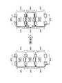
- FIG. 1is a diagram illustrating the configuration of a network including a transmission apparatus according to the first embodiment.
- FIG. 2is a diagram for explaining a failure recovery method by the transmission apparatus according to the second embodiment.
- FIG. 3is a block diagram illustrating the configuration of the transmission apparatus according to the second embodiment.
- FIG. 4is a flowchart illustrating a processing procedure performed by the transmission apparatus according to the second embodiment.
- FIG. 5is a diagram for explaining a failure recovery method by the transmission apparatus according to the third embodiment.
- FIG. 6is a block diagram illustrating the configuration of the transmission apparatus according to the third embodiment.
- FIG. 7is a flowchart illustrating a processing procedure performed by the transmission apparatus according to the third embodiment.
- FIG. 8is a diagram for explaining another configuration example 1 of the transmission apparatus.
- FIG. 9is a diagram for explaining another configuration example 2 of the transmission apparatus.
- FIG. 10is a diagram for explaining another configuration example 3 of the transmission apparatus.
- FIG. 11is a diagram showing a
- FIG. 1is a diagram illustrating the configuration of a network including a transmission apparatus according to the first embodiment.
- the network shown in FIG. 1has a multi-ring configuration including three rings 1 to 3.
- the ring 1connects the transmission apparatuses 10a, 10b, 10c, 10d, and 10e.
- the ring 2connects the transmission devices 10a, 10f, 10g, 10h, and 10e.
- the ring 3connects the transmission apparatuses 10a, 10i, 10j, 10k, and 10e.
- three rings 1 to 3 and eleven transmission devices 10a to 10kare shown.
- the number of rings and transmission devicesis not limited to this.
- the network shown in FIG. 1shares a section between the transmission device 10a and the transmission device 10e in the rings 1 to 3.
- the transmission device 10a and the transmission device 10e installed in the common unitare transmission devices according to the present embodiment.
- the other transmission apparatusis a known transmission apparatus applied to the APS / BLSR ring network. Since both the transmission device 10a and the transmission device 10e according to the present embodiment have the same configuration, the transmission device 10a will be described below as an example.
- the transmission device 10 aincludes a determination unit 11 and a mapping unit 12.
- the determining unit 11determines whether or not the received frame includes failure information indicating that a failure has occurred in each of the rings 1 to 3.
- the mapping unit 12maps the frame determined by the determining unit 11 to include failure information to a shared frame that is a frame used in the shared units of the plurality of rings 1 to 3.
- the transmission device 10d of the ring 1communicates with the transmission device 10j of the ring 3 using the path P1 passing through the transmission devices 10c, 10b, and 10a of the ring 1 and the transmission devices 10a and 10i of the ring 3. Frames shall be sent and received between them.
- the transmission device 10h of the ring 2transmits a frame between the transmission device 10j of the ring 3 using the path P2 passing through the transmission devices 10g, 10f and 10a of the ring 2 and the transmission devices 10a and 10i of the ring 3. Shall be sent and received.
- the determination unit 11determines whether failure information is included in the frames received from the rings 1 to 3 and determines that failure information is not included. Since the failure information is not included in the frames received from the rings 1 to 3, the mapping unit 12 does not map these frames to the shared frames.
- the transmission device 10b and the transmission device 10cdetect the failure 13
- the transmission device 10b and the transmission device 10cinclude the failure information indicating that the failure has occurred in the ring 1 in the frame, and the frame including the failure information is connected to the path P1 used so far Switch to the backup path P3 on the opposite side and transmit.
- the determination unit 11determines whether or not failure information is included in the frames received from the rings 1 to 3, and failure information indicating that a failure has occurred in the ring 1 is present. It is determined that it is included.
- the mapping unit 12maps the frame from the ring 1 determined to include the failure information by the determination unit 11 to the shared frame, and transmits the mapped shared frame to the transmission device 10a and the transmission device which are the shared unit 10e is sent to the line.
- the transmission device 10d in the ring 1can resume frame transmission / reception with the transmission device 10j in the ring 3.
- the frame from the transmission device 10j in the ring 3reaches the transmission device 10b in the ring 1 via the transmission devices 10i and 10a, and further returns by the transmission device 10b to return to the transmission device 10a.
- the frame from the transmission device 10j on the ring 3is mapped to the shared frame by the transmission device 10a, and the shared frame after mapping is transmitted from the transmission device 10a to the transmission device 10e.
- the frame from the transmission device 10j in the ring 3is demapped from the shared frame by the transmission device 10e, then reaches the transmission device 10c via the transmission device 10d, and is further turned back by the transmission device 10c.
- the transmission device 10dis reached.
- the transmission device 10awhen the failure information is included in the frame received from each ring in the network sharing a part of the plurality of rings, the transmission device 10a according to the first embodiment rings the frame from the ring including the failure information. It maps to the shared frame used in the shared part. For this reason, the transmission apparatus 10a can recover from the failure only by using the failure information of the existing APS byte stored in the overhead of the frame, and the unique switching processing in the conventional multi-ring configuration can be omitted. . As a result, the transmission device 10a can simplify the process associated with the failure recovery.
- the transmission apparatus described in the first embodimentwill be described using a specific example.
- the transmission apparatus described in the first embodimentis connected to the ITU-T recommendation G.264.
- An example applied to a transmission apparatus that employs the OTN defined by 709will be described.
- OTNis a transmission method that accommodates data in a frame called an OTU (Optical channel Transport Unit) frame standardized by ITU-T.
- OTUOptical channel Transport Unit
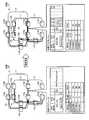
- FIG. 2is a diagram for explaining a failure recovery method by the transmission apparatus according to the second embodiment.
- the network shown in FIG. 2has a multi-ring configuration including three rings 1 to 3.
- the ring 1connects the transmission apparatuses 110a, 110b, 110c, 110d, and 110e.
- Ring 2connects transmission devices 110a, 110f, 110g, 110h, and 110e.
- Ring 3connects transmission devices 110a, 110i, 110j, 110k, and 110e.
- three rings 1 to 3 and eleven transmission devices 110a to 110kare shown. However, the number of rings and transmission devices is not limited to this.
- the network shown in FIG. 2shares a section between the transmission device 110a and the transmission device 110e in the rings 1 to 3.
- the transmission apparatus 110a and the transmission apparatus 110e installed in the shared unitare transmission apparatuses that execute the failure recovery method according to the present embodiment.
- the other transmission apparatusis a known transmission apparatus applied to the APS / BLSR ring network. Since both the transmission apparatus 110a and the transmission apparatus 110e according to the present embodiment have the same configuration, the transmission apparatus 110a will be described below as an example.
- the failure recovery methodwhen failure information is included in an OTU frame received from each ring in a network sharing a part of a plurality of rings, the OTU frame from the ring including the failure information is shared by the ring. Map to the OTU frame used in the part.
- the transmission device 110d of the ring 1communicates with the transmission device 110j of the ring 3 using the path P1 that passes through the transmission devices 110c, 110b, and 110a of the ring 1 and the transmission devices 110a and 110i of the ring 3. It is assumed that an OTU frame is transmitted / received between them.
- the transmission device 110h in the ring 2transmits an OTU between the transmission device 110j in the ring 3 using the path P2 that passes through the transmission devices 110g, 110f, and 110a in the ring 2 and the transmission devices 110a and 110i in the ring 3. Frames are sent and received.
- the transmission apparatus 110adetermines whether or not failure information is included in the OTU frames received from the rings 1 to 3, and determines that failure information is not included. For this reason, the transmission apparatus 110a does not map these OTU frames to an OTU frame (hereinafter referred to as a “shared OTU frame”) used on a line between the transmission apparatus 110a and the transmission apparatus 110e, which are shared units. Therefore, the OPU (Optical channel Payload Unit) -Payload of the shared OTU frame is null indicating that no data is accommodated (state 20).
- OPUOptical channel Payload Unit
- APS / PCCAutomatic Protection Switching / Protection Communication Channel of ODU-OH (Optical Data Unit Overhead) of the shared OTU frame associates MFAS (Multi-Frame Alignment Signal), Ring #, and State.
- the MFASindicates the type of the OTU frame that is mapped to the shared OTU frame.
- Ring #indicates an identifier for uniquely identifying a ring in which an OTU frame indicated by MFAS is transmitted.
- Stateindicates the state of the ring identified by Ring #, and stores NR (No Request) indicating normal operation and SF (Signal Fail) indicating signal disconnection. For example, in the normal operation state described above, the state state of Ring # “1” (ring 1) in which the OTU frame indicated by MFAS “*** 0001” is transmitted is “NR” (normal operation). I understand that.
- the transmission apparatus 110adetermines whether or not failure information is included in the OTU frames received from the rings 1 to 3, and indicates failure information indicating that a failure has occurred in the ring 1. Is determined to be included.
- the transmission apparatus 110amaps the OTU frame from the ring 1 determined to contain the failure information to the shared OTU frame, and the shared frame after the mapping is transmitted to the transmission apparatus 110a and the transmission apparatus 110e that are the shared units.
- ODUxwhich is the ODU of the OTU frame from ring 1
- OPU-Payload of the shared OTU framestate 21
- the state state of Ring # “1” (ring 1) in which the OTU frame indicated by the MFAS “*** 0001” is transmittedis “ NR "(normal operation) is changed to” SF "(signal loss).
- the transmission device 110d in the ring 1can resume transmission and reception of the OTU frame with the transmission device 110j in the ring 3. .
- an OTU frame from the transmission device 110j on the ring 3reaches the transmission device 110b on the ring 1 via the transmission devices 110i and 110a, and further returns by the transmission device 110b to return to the transmission device 110a.
- the OTU frame from the transmission apparatus 110jis mapped to the shared OTU frame by the transmission apparatus 110a, and the mapped shared OTU frame is transmitted from the transmission apparatus 110a to the transmission apparatus 110e.
- the OTU frame from the transmission device 110jis demapped from the shared OTU frame by the transmission device 110e, and then reaches the transmission device 110c via the transmission device 110d.
- Device 110dis reached.
- failure recovery methodwhen failure information is included in an OTU frame received from each ring in a network sharing a part of a plurality of rings, an OTU frame from the ring including the failure information is included. To the shared OTU frame.
- the failureis recovered only by using the failure information of the existing APS / PCC byte stored in the OH of the OTU frame. Then, it is no longer necessary to perform an original switching process or the like when recovering from the failure.
- FIG. 3is a block diagram illustrating the configuration of the transmission apparatus 110a according to the second embodiment.
- the transmission apparatus 110aincludes an interface (IF) card 120, an IF card 130, an IF card 140, and a switch (SW) card 150.
- the transmission apparatus 110 aincludes a CPU (Central Processing Unit) card 160 and a shared IF card 170.
- IFinterface
- SWswitch
- the number of IF cardsmay be any number.
- the IF card 120is a processing unit that processes an OTU frame input from the ring 1 or output to the ring 1 and processes an ODU frame input from the shared IF card 170 or output to the shared IF card 170.
- the IF card 120includes an OTU processing unit 121, an ODU processing unit 122, and an ODU redundancy processing unit 123.
- the OTU processing unit 121When receiving the OTU frame from ring 1, the OTU processing unit 121 separates the received OTU frame into an ODU frame and OH, outputs the ODU frame to the ODU processing unit 122, and executes predetermined processing using OH. To do. Further, when receiving the ODU frame from the ODU processing unit 122, the OTU processing unit 121 generates an OTU frame by adding OH to the received ODU frame, and outputs the generated OTU frame to the ring 1.
- the ODU processing unit 122extracts the APS / PCC from the OH of the ODU frame input from the OTU processing unit 121, outputs the extracted APS / PCC to the CPU card 160, and outputs the extracted ODU frame to the ODU redundancy processing unit. To 123.
- the ODU processing unit 122delivers the ODU frame input from the ODU redundancy processing unit 123 to the OTU processing unit 121.
- the ODU redundancy processing unit 123outputs the ODU frame input from the ODU processing unit 122 to the SW card 150 when the protection instruction is not received from the APS processing unit 163, that is, in a normal operation state. Further, the ODU redundancy processing unit 123 delivers the ODU frame input from the SW card 150 to the ODU processing unit 122 in the normal operation state.
- the ODU redundancy processing unit 123outputs the ODU frame input from the ODU processing unit 122 to the SW card 150 and the shared IF card 170 when a protection instruction is received from the APS processing unit 163, that is, when a failure occurs. To do. Also, the ODU redundancy processing unit 123 delivers the ODU frame input from the SW card 150 and the shared IF card 170 to the ODU processing unit 122 when a failure occurs.
- the IF card 130processes an OTU frame input from the ring 2 or an OTU frame output to the ring 2 and processes an ODU frame input from the shared IF card 170 or an ODU frame output to the shared IF card 170 Part.
- the IF card 130includes an OTU processing unit 131, an ODU processing unit 132, and an ODU redundancy processing unit 133.
- the OTU processing unit 131, the ODU processing unit 132, and the ODU redundancy processing unit 133have the same configurations as the OTU processing unit 121, the ODU processing unit 122, and the ODU redundancy processing unit 123, respectively, and thus description thereof is omitted.
- the IF card 140processes an OTU frame input from the ring 3 or an OTU frame output to the ring 3, and processes an ODU frame input from the shared IF card 170 or an ODU frame output to the shared IF card 170 Part.
- the IF card 140includes an OTU processing unit 141, an ODU processing unit 142, and an ODU redundancy processing unit 143.
- the OTU processing unit 141, the ODU processing unit 142, and the ODU redundancy processing unit 143have the same configurations as the OTU processing unit 121, the ODU processing unit 122, and the ODU redundancy processing unit 123, respectively, and thus description thereof is omitted.
- SW card 150is a processing unit that executes switching processing between different rings.
- the SW card 150has a SW unit 151.
- the SW unit 151outputs the ODU frame input from the rings 1 to 3 via the IF cards 120 to 140 to a predetermined transfer destination IF card.
- the SW unit 151outputs an ODU frame input from the ring 1 via the IF card 120 to the IF card 140 that is a predetermined transfer destination.
- the CPU card 160is a control unit that manages and supervises failure recovery processing by the transmission apparatus 110a, and includes an APS information storage unit 161, a PSI information storage unit 162, and an APS processing unit 163.
- the APS processing unit 163is an example of the determination unit 11 in the first embodiment.
- the APS information storage unit 161stores APS information indicating the state of each ring. Specifically, the APS information storage unit 161 stores items such as MFAS, Ring #, and State in association with each other as APS information.
- the MFASindicates the type of the OTU frame that is mapped to the shared OTU frame.
- Ring #indicates an identifier for uniquely identifying a ring in which an OTU frame indicated by MFAS is transmitted.
- Stateindicates the state of the ring identified by Ring #, and stores NR (No Request) indicating normal operation and SF (Signal Fail) indicating signal disconnection.
- the PSI information storage unit 162stores PSI (Payload Structure Identifier) information that is information indicating what data is stored in the OPU-Payload of the shared OTU frame. Specifically, the PSI information storage unit 162 stores items such as TS # and accommodation ODU in association with each other as PSI information.
- TS #indicates an identifier for uniquely identifying a TS (Tributary slot) which is a data accommodation area obtained by dividing a plurality of OPU-Payloads of the shared OTU frame.
- the accommodation ODUindicates the ODU actually accommodated in the TS identified by TS #.
- the APS processing unit 163determines whether or not the OTU frame received from each of the rings 1 to 3 includes failure information indicating that a failure has occurred in each of the rings 1 to 3. Specifically, the APS processing unit 163 analyzes the APS / PCC input from the ODU processing units 122, 132, and 142, and indicates failure information that indicates signal interruption for each OTU frame received from each of the rings 1 to 3. It is determined whether or not SF is included.
- the APS processing unit 163maintains the state of each Ring # at “NR” (normal operation) in the APS information storage unit 161. At the same time, the APS processing unit 163 maintains the accommodation ODU of each TS # at “null” in the PSI information storage unit 162.
- the APS processing unit 163sets the Ring # State including SF in the APS information storage unit 161 to “ NR "(normal operation) is changed to" SF "(signal loss). For example, when SF is included in the OTU frame received from ring 1, the APS processing unit 163 changes the State of Ring # “1” corresponding to ring 1 to “SF”.
- the APS processing unit 163changes the accommodation ODU of the TS # determined in advance according to the Ring # containing the SF to an ODU that is actually accommodated. For example, if the ODU of the OTU frame received from the ring 1 is ODUx, and if the SF is included in the OTU frame, TS # “1” to “#” determined in advance according to the Ring # “1”. The accommodation ODU of “3” is changed from “null” to “ODUx”.
- the APS processing unit 163instructs the ODU redundancy processing units 123, 133, and 143 to perform protection processing when any of the OTU frames received from the rings 1 to 3 includes SF. Output protection instructions.
- the shared IF card 170processes an ODU frame that is input from the IF cards 120, 130, and 140 or output to the IF cards 120, 130, and 140, and a process that processes a shared OTU frame that is input from the shared unit or output to the shared unit Part.
- the shared IF card 170includes a LO (Lower Order) -ODU transmission / reception units 171 to 173, a HO (Higher-Order) -ODU processing unit 174, and an OTU processing unit 175.
- the HO-ODU processing unit 174is an example of the mapping unit 12 in the first embodiment.
- the LO-ODU transmission / reception units 171 to 173output the ODU frames input from the IF cards 120, 130, and 140 to the HO-ODU processing unit 174, respectively.
- the LO-ODU transmission / reception units 171 to 173output the ODU frames input from the HO-ODU processing unit 174 to the IF cards 120, 130, and 140, respectively.
- the HO-ODU processing unit 174maps the OTU frame determined to contain SF by the APS processing unit 163 to the shared OTU frame, and outputs the mapped shared OTU frame to the OTU processing unit 175. Specifically, the HO-ODU processing unit 174 refers to the APS information storage unit 161 and identifies the ring identified by Ring # whose ring state State is “SF” (signal loss). The HO-ODU processing unit 174 then receives the ODU frame input from the LO-ODU transmission / reception unit corresponding to the specified ring with respect to the OPU-Payload of the shared OTU frame indicated by TS # of the PSI information storage unit 162. To map. Then, the HO-ODU processing unit 174 outputs the shared OTU frame in which the ODU frame is mapped to the OTU processing unit 175.
- the HO-ODU processing unit 174causes the Ring # “1” ”Is identified. Then, the HO-ODU processing unit 174 outputs the LO-ODU transmission / reception unit 171 corresponding to the ring 1 to the OPU-Payload of the shared OTU frame indicated by TS # “1” to “3” of the PSI information storage unit 162. The ODU frame input from is mapped. Then, the HO-ODU processing unit 174 outputs the shared OTU frame in which the ODU frame is mapped to the OTU processing unit 175.
- the HO-ODU processing unit 174demaps an ODU frame determined by the APS processing unit 163 as containing SF from a later-described shared ODU frame input from the OTU processing unit 175. Then, the HO-ODU processing unit 174 outputs the demapped ODU frame to the LO-ODU transmission / reception units 171 to 173.
- the OTU processing unit 175stores various operation management information in the OH of the shared OTU frame input from the HO-ODU processing unit 174, and outputs the stored shared OTU frame to the shared unit.
- the OTU processing unit 175receives the shared OTU frame from the shared unit, the OTU processing unit 175 separates the received shared OTU frame into an ODU frame and an OH, and separates the separated ODU frame (hereinafter referred to as “shared ODU frame”) into the HO-ODU.
- the datais output to the processing unit 174. Further, the OTU processing unit 175 executes a predetermined process using the separated OH.
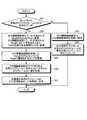
- FIG. 4is a flowchart illustrating a processing procedure performed by the transmission apparatus 110a according to the second embodiment.
- the processing procedure of the CPU card 160 and the shared IF card 170 in the transmission apparatus 110awill be described.
- the APS processing unit 163 of the CPU card 160analyzes the APS / PCC input from the ODU processing units 122, 132, and 142, and for each OTU frame received from each ring 1 to 3, It is determined whether or not SF is included (step S11).
- the APS processing unit 163maintains the APS information storage unit 161 and the PSI information storage unit 162 as they are (Step S12), Exit. That is, the APS processing unit 163 maintains the state of each Ring # at “NR” (normal operation) in the APS information storage unit 161, and sets the accommodation ODU of each TS # to “null” in the PSI information storage unit 162. To maintain.
- the APS processing unit 163causes the APS information storage unit 161 to include the Ring including the SF. Change #State to “SF” (signal cut off). At the same time, the APS processing unit 163 changes, in the PSI information storage unit 162, the accommodation ODU of the TS # determined in advance according to the Ring # including the SF to an ODU that is actually accommodated (step S13).
- the APS processing unit 163changes the state of Ring # “1” corresponding to ring 1 from “NR” (normal operation) to “SF”. "(Signal loss).
- the APS processing unit 163changes the accommodated ODUs of TS # “1” to “3” determined in advance according to Ring # “1” from “null” to “ODUx”.
- the HO-ODU processing unit 174 of the shared IF card 170refers to the APS information storage unit 161 and selects the ring identified by the Ring # whose ring state is “SF” (signal cut). Specify (step S14). The HO-ODU processing unit 174 then receives the ODU frame input from the LO-ODU transmission / reception unit corresponding to the specified ring with respect to the OPU-Payload of the shared OTU frame indicated by TS # of the PSI information storage unit 162. Are mapped (step S15). Then, the HO-ODU processing unit 174 outputs the shared OTU frame that maps the ODU frame to the shared unit via the OTU processing unit 175 (step S16).
- the HO-ODU processing unit 174causes the Ring # “1” ”Is identified. Then, the HO-ODU processing unit 174 outputs the LO-ODU transmission / reception unit 171 corresponding to the ring 1 to the OPU-Payload of the shared OTU frame indicated by TS # “1” to “3” of the PSI information storage unit 162. The ODU frame input from is mapped. Then, the HO-ODU processing unit 174 outputs the shared OTU frame to which the ODU frame is mapped to the shared unit via the OTU processing unit 175.
- the transmission apparatus 110amaps the OTU frame from the ring including the SF to the shared OTU frame. To do. For this reason, the transmission apparatus 110a can recover from the failure only by using the failure information of the existing APS / PCC byte stored in the OH of the OTU frame, and performs a unique switching process as in the conventional multi-ring configuration. Can be omitted. As a result, the transmission apparatus 110a can simplify the process associated with failure recovery.
- an exampleis shown in which an OTU frame determined to include SF is mapped to a shared OTU frame, and the mapped shared OTU frame is output to the shared unit.
- a part of the OTU frame determined not to include the SFis mapped in advance to the shared OTU frame, and it is determined that the SF is included in the OTU frame, a part of the OTU frame mapped in advance. May be extended. Therefore, in the third embodiment, a part of the OTU frame that is determined not to include the SF is mapped in advance to the shared OTU frame, and is mapped in advance when it is determined that the SF is included in the OTU frame. An example of extending a part of the OTU frame will be described.
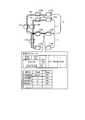
- FIG. 5is a diagram for explaining a failure recovery method by the transmission apparatus according to the third embodiment.
- the same parts as those already described with reference to FIG. 2are denoted by the same reference numerals, and detailed description thereof is omitted.
- the network shown in FIG. 5shares sections of the transmission device 110a and the transmission device 110e in the rings 1 to 3.
- the transmission apparatus 110a and the transmission apparatus 110e installed in the shared unitare transmission apparatuses that execute the failure recovery method according to the present embodiment.
- the other transmission apparatusis a known transmission apparatus applied to the APS / BLSR ring network. Since both the transmission apparatus 110a and the transmission apparatus 110e according to the present embodiment have the same configuration, the transmission apparatus 110a will be described below as an example.
- the transmission apparatus 110adetermines whether or not SF is included in the OTU frame received from each of the rings 1 to 3, and determines that SF is not included.
- the transmission apparatus 110aconverts a part of the OTU frame that is determined not to include SF into a shared OTU frame that is used in a line between the transmission apparatus 110a and the transmission apparatus 110e, which is a shared unit, in advance. Mapping is performed (state 30).
- the transmission apparatus 110adetermines that the SF is not included in the OTU frame received from the ring 1, it maps a part of the OTU frame received from the ring 1 to the shared OTU frame in advance.
- the transmission apparatus 110adetermines whether or not failure information is included in the OTU frames received from the rings 1 to 3, and indicates failure information indicating that a failure has occurred in the ring 1. Is determined to be included.
- the transmission apparatus 110amaps the OTU frame to the shared OTU frame by extending a part of the OTU frame mapped in advance to the shared OTU frame.
- ODUxwhich is the ODU of the OTU frame from ring 1, is accommodated in the OPU-Payload of the shared OTU frame (state 31).
- the failure 113 that has occurred in the ring 1is recovered, and the transmission device 110d in the ring 1 can resume transmission and reception of the OTU frame with the transmission device 110j in the ring 3. .
- a part of the OTU frame determined not to include the SFis mapped in advance to the shared OTU frame, and it is determined that the SF is included in the OTU frame. If this happens, a part of the previously mapped OTU frame is expanded. Thereby, in the failure recovery method according to the present embodiment, it is possible to efficiently map the OTU frame from the ring including the SF to the shared OTU frame.
- FIG. 6is a block diagram illustrating the configuration of the transmission apparatus 110a according to the third embodiment.
- the same components as those already described with reference to FIG. 3are denoted by the same reference numerals, and detailed description thereof is omitted.
- the transmission apparatus 110ahas a shared IF card 180 instead of the shared IF card 170 shown in FIG.
- the shared IF card 180processes an ODU frame that is input from or output to the IF cards 120, 130, and 140 from the IF cards 120, 130, and 140, and a process that processes a shared OTU frame that is input from the shared unit or output to the shared unit Part.
- the shared IF card 180includes LO-ODU transmission / reception units 181 to 183, a HO-ODU processing unit 184, and an OTU processing unit 175.
- the LO-ODU transmission / reception units 181 to 183 and the HO-ODU processing unit 184are examples of the mapping unit 12 in the first embodiment.
- the LO-ODU transmission / reception units 181 to 183output the ODU frames input from the IF cards 120, 130, and 140 to the HO-ODU processing unit 184, respectively.
- the LO-ODU transmission / reception units 181 to 183output the ODU frame input from the HO-ODU processing unit 184 to the IF cards 120, 130, and 140, respectively.
- the LO-ODU transmission / reception units 181 to 183pre-map a part of the OTU frame determined by the APS processing unit 163 as not including the SF to the shared OTU frame.
- the LO-ODU transmission / reception units 181 to 183refer to the APS information storage unit 161 and specify the ring identified by the Ring # whose ring state is “NR” (normal operation). To do. Then, the LO-ODU transmission / reception units 181 to 183 map a part of the OTU frame received from the specified ring in advance to the shared OTU frame.
- the HO-ODU processing unit 184extends a part of the OTU frame mapped in advance to the shared OTU frame, and converts the expanded shared OTU frame into the OTU frame.
- the datais output to the processing unit 175.
- the HO-ODU processing unit 184refers to the APS information storage unit 161 and identifies the ring identified by the Ring # whose ring state state is “SF” (signal loss). Then, the HO-ODU processing unit 184 extends a part of the OTU frame mapped in advance to the shared OTU frame indicated by TS # in the PSI information storage unit 162. Then, the HO-ODU processing unit 184 outputs a shared OTU frame obtained by extending a part of the OTU frame to the OTU processing unit 175.
- the HO-ODU processing unit 184demaps the ODU frame determined by the APS processing unit 163 as including SF from the shared ODU frame input from the OTU processing unit 175. Then, the HO-ODU processing unit 184 outputs the demapped ODU frame to the LO-ODU transmission / reception units 181 to 183.
- FIG. 7is a flowchart illustrating a processing procedure performed by the transmission apparatus 110a according to the third embodiment.
- the processing procedure of the CPU card 160 and the shared IF card 180 in the transmission apparatus 110awill be described.
- the APS processing unit 163 of the CPU card 160analyzes the APS / PCC input from the ODU processing units 122, 132, and 142, and for each OTU frame received from each ring 1 to 3, It is determined whether or not SF is included (step S21).
- the APS processing unit 163maintains the APS information storage unit 161 and the PSI information storage unit 162 as they are (Step S22). That is, the APS processing unit 163 maintains the state of each Ring # at “NR” (normal operation) in the APS information storage unit 161, and sets the accommodation ODU of each TS # to “null” in the PSI information storage unit 162. To maintain. Then, the LO-ODU transmission / reception units 181 to 183 of the shared IF card 180 map in advance a part of the OTU frame determined by the APS processing unit 163 that SF is not included to the shared OTU frame (step S23).
- the APS processing unit 163causes the APS information storage unit 161 to include the Ring including the SF. Change #State to “SF” (signal cut off).
- the APS processing unit 163changes the accommodation ODU of the TS # predetermined according to the Ring # including the SF to an ODU that is actually accommodated (step S24).
- the APS processing unit 163changes the state of Ring # “1” corresponding to ring 1 from “NR” (normal operation) to “SF”. "(Signal loss).
- the APS processing unit 163changes the accommodated ODUs of TS # “1” to “3” determined in advance according to Ring # “1” from “null” to “ODUx”.
- the HO-ODU processing unit 184 of the shared IF card 180refers to the APS information storage unit 161 to identify the ring identified by the Ring # whose ring state is “SF” (signal cut). Specify (step S25). Then, the HO-ODU processing unit 184 extends a part of the OTU frame mapped in advance to the shared OTU frame indicated by TS # in the PSI information storage unit 162 (step S26). Then, the HO-ODU processing unit 184 outputs the shared OTU frame obtained by extending a part of the OTU frame to the shared unit via the OTU processing unit 175 (step S27).
- the transmission apparatus 110amaps a part of the OTU frame that is determined not to include the SF to the shared OTU frame in advance, and when it is determined that the SF is included in the OTU frame, A part of the previously mapped OTU frame is extended. Thereby, the transmission apparatus 110a can efficiently map the OTU frame from the ring including the SF to the shared OTU frame.
- the present inventionis not limited to this.
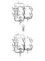
- another configuration example of the transmission apparatus 110awill be described with reference to FIG.
- FIG. 8is a diagram for explaining another configuration example 1 of the transmission apparatus 110a.
- the section between the transmission device 110a and the transmission device 110e, which are shared units,may be connected by two parallel links.
- the OPS-PCC of the ODU-OH of the shared OTU framedefines the shared OTU frame in the MFAS “*** 0000” and defines one link “Share1” in the corresponding Ring #. To do.
- the state state of Ring # “Share1” (one link) in which the shared OTU frame indicated by MFAS “*** 0000” is transmittedis changed from “NR” (normal operation) to “ When “SF” (signal loss), the shared OTU frame is forcibly output to the other link.
- the determination unitreceives the shared OTU received from one of the two parallel links that connect the sections of the transmission device 110a and the transmission device 110e that are the common units. It is determined whether or not the frame includes failure information indicating that a failure has occurred in the one link. Then, the mapping unit maps the shared OTU frame determined by the determination unit to include failure information to a shared OTU frame used on the other link other than the one link on which the failure has occurred. For this reason, according to the configuration example 1, link redundancy can be provided for the section between the transmission device 110a and the transmission device 110e, which are shared units. In the example illustrated in FIG. 8, an example in which the sections of the transmission apparatus 110a and the transmission apparatus 110e that are shared units are connected by two parallel links is shown. However, the number of links that connect the shared units is 2 There may be more than one.
- the transmission apparatus 110aoutputs an OTU frame toward the transmission apparatus 110b in the vicinity of the failure 113 that has occurred in the ring 1, and receives the OTU frame returned by the transmission apparatus 110b.
- the transmission apparatus 110ait is not limited to this.
- another configuration example of the transmission apparatus 110awill be described with reference to FIG.
- FIG. 9is a diagram for explaining another configuration example 2 of the transmission apparatus 110a.
- the transmission apparatus 110 amay output an OTU frame toward the transmission apparatus 110 i in the ring 3 instead of the transmission apparatus 110 b in the vicinity of the failure 113 generated in the ring 1.
- the detection of a failure and the change of the output target of the OTU frameare described in G. It is realized by using the TCM (Tandem Connection Monitoring) function defined in 709.
- the transmission device disclosed in the present applicationis applied to the transmission device 110a and the transmission device 110e installed in one common unit in a multi-ring configuration including three rings 1 to 3.
- the present inventionis not limited to this.
- the transmission apparatus disclosed in the present applicationcan also be applied to the transmission apparatuses A, B, F, and E installed in two shared units in a multi-ring configuration as shown in FIG.
- FIG. 10is a diagram for explaining another configuration example 3 of the transmission apparatus.
- each component of each illustrated apparatusis functionally conceptual, and does not necessarily need to be physically configured as illustrated.
- the specific form of distribution / integration of each deviceis not limited to that shown in the figure, and all or a part thereof may be functionally or physically distributed or arbitrarily distributed in arbitrary units according to various loads or usage conditions. Can be integrated and configured.
- all or any part of each processing function performed in each devicemay be realized by a CPU and a program analyzed and executed by the CPU, or may be realized as hardware by wired logic.
- Each process described in the present embodimentcan be realized by executing a prepared program on a computer such as a personal computer or a workstation.
- This programcan be distributed via a network such as the Internet.
- the programcan also be executed by being recorded on a computer-readable recording medium such as a hard disk, a flexible disk (FD), a CD-ROM, an MO, and a DVD and being read from the recording medium by the computer.
- a computer-readable recording mediumsuch as a hard disk, a flexible disk (FD), a CD-ROM, an MO, and a DVD and being read from the recording medium by the computer.
- Determination unit 12Mapping unit 120, 130, 140 IF card 121, 131, 141 OTU processing unit 122, 132, 142 ODU processing unit 123, 133, 143 ODU redundancy processing unit 150 SW card 151 SW unit 160 CPU card 161 APS information storage unit 162 PSI information storage unit 163 APS processing unit 170, 180 Shared IF cards 171 to 173, 181 to 183 LO-ODU transmission / reception unit 174, 184 HO-ODU processing unit 175 OTU processing unit
Landscapes
- Engineering & Computer Science (AREA)
- Computer Networks & Wireless Communication (AREA)
- Signal Processing (AREA)
- Physics & Mathematics (AREA)
- Electromagnetism (AREA)
- Computing Systems (AREA)
- Small-Scale Networks (AREA)
Abstract
Description
Translated fromJapanese本発明は、伝送装置、障害復旧方法及びネットワークシステムに関する。The present invention relates to a transmission device, a failure recovery method, and a network system.
近年、大容量のデータ伝送に対する需要の拡大に伴い、高速なディジタル伝送方式を用いて大規模なネットワークを構築することが行われている。ディジタル伝送方式の規格としては、国際電気通信連合(ITU-T:International Telecommunication Union Telecommunication standardization sector)の勧告G.709により規定されたOTN(Optical Transport Network)を用いることが検討されている。OTNは、ディジタル化された主信号(ペイロード)に対して伝送装置等の保守運用を行うための信号(オーバーヘッド)が付加された信号であるフレームを伝送するものである。In recent years, with the expansion of demand for large-capacity data transmission, a large-scale network is being constructed using a high-speed digital transmission system. As a standard of the digital transmission system, Recommendation G. of International Telecommunication Union Telecommunication standardization sector (ITU-T). The use of OTN (Optical Transport Network) defined by 709 is under consideration. The OTN transmits a frame that is a signal in which a signal (overhead) for performing maintenance operation of a transmission apparatus or the like is added to a digitized main signal (payload).
OTNを用いて大規模なネットワークを構築する方式としては、例えば、伝送装置間をリング状の回線で接続するBLSR(Bi-directional Line Switched Ring)方式がある。そして、BLSR方式で構築されたリングネットワークには、障害発生時にネットワークを復旧するためのAPS(Automatic Protection Switching)機能を採用するものが存在する。APS機能を採用するBLSR方式のリングネットワーク(以下「APS/BLSRリングネットワーク」という)では、フレームのオーバーヘッドに格納されるAPSバイトを伝送装置間で互いに通知し合うことで、高速な障害復旧を実現している。例えば、APS/BLSRリングネットワークでは、障害として信号断(SF:Signal Fail)が発生した際に、SFを格納したAPSバイトを用いて隣接する装置へ自装置の情報を通知し、現在運用している回線を予備側の回線へ切り替えることでネットワークを復旧する。As a method for constructing a large-scale network using OTN, for example, there is a BLSR (Bi-directional Line Switched Ring) method in which transmission apparatuses are connected by a ring-shaped line. Some ring networks constructed by the BLSR method employ an APS (Automatic Protection Switching) function for restoring the network when a failure occurs. In the BLSR ring network (hereinafter referred to as “APS / BLSR ring network”) that employs the APS function, APS bytes stored in the frame overhead are mutually notified between the transmission devices, thereby realizing high-speed failure recovery. is doing. For example, in an APS / BLSR ring network, when a signal failure (SF) occurs as a failure, information on the own device is notified to an adjacent device using an APS byte storing SF, and is currently operated. The network is restored by switching the existing line to the backup line.
ここで、更なる大規模ネットワークを構築しようとした場合、複数のリングネットワークを相互に接続したマルチリング構成を実現することが望まれる。このようなマルチリング構成としては、図11に示したものが提案されている。図11は、従来のマルチリング構成を示す図である。同図に示すように、従来のマルチリング構成では、リングネットワークA内の2つの伝送装置とリングネットワークB内の2つの伝送装置とが相互に接続される。Here, when a further large-scale network is to be constructed, it is desired to realize a multi-ring configuration in which a plurality of ring networks are connected to each other. As such a multi-ring configuration, the one shown in FIG. 11 has been proposed. FIG. 11 is a diagram showing a conventional multi-ring configuration. As shown in the figure, in the conventional multi-ring configuration, two transmission apparatuses in the ring network A and two transmission apparatuses in the ring network B are connected to each other.
しかしながら、上記した従来のマルチリング構成では、リングネットワーク内にてAPSバイトの通知を行うことに加えて、相互に接続された計4つの伝送装置間で独自のスイッチング処理を行うため、障害復旧に伴う処理が複雑化するという問題がある。However, in the conventional multi-ring configuration described above, in addition to notifying the APS byte in the ring network, a unique switching process is performed between a total of four transmission devices connected to each other, so that it is possible to recover from a failure. There is a problem that the accompanying processing becomes complicated.
開示の技術は、上述した従来技術の課題を解決するためになされたものであり、障害復旧に伴う処理を簡素化することができる伝送装置、障害復旧方法及びネットワークシステムを提供することを目的とする。The disclosed technology has been made to solve the above-described problems of the prior art, and aims to provide a transmission device, a failure recovery method, and a network system that can simplify the processing associated with failure recovery. To do.
本願の開示する伝送装置は、複数のリングの一部を共用して構成されたネットワークにおける前記各リングからフレームを受信した場合に、受信されたフレームに、前記各リングにて障害が発生したことを示す障害情報が含まれているか否かを判定する判定部と、前記判定部によって前記障害情報が含まれていると判定された前記フレームを、前記複数のリングの共用部で用いられるフレームである共用フレームにマッピングするマッピング部とを備えた。In the transmission device disclosed in the present application, when a frame is received from each ring in a network configured by sharing a part of a plurality of rings, a failure occurs in each received ring in the ring. A determination unit that determines whether or not failure information is included, and the frame that is determined by the determination unit to include the failure information is a frame that is used in a shared unit of the plurality of rings. And a mapping unit for mapping to a shared frame.
本願の開示する伝送装置の一つの態様によれば、障害復旧に伴う処理を簡素化することができるという効果を奏する。According to one aspect of the transmission device disclosed in the present application, it is possible to simplify processing associated with failure recovery.
以下に、本願の開示する伝送装置、障害復旧方法及びネットワークシステムの実施例を図面に基づいて詳細に説明する。Hereinafter, embodiments of a transmission device, a failure recovery method, and a network system disclosed in the present application will be described in detail with reference to the drawings.
まず、実施例1に係る伝送装置の構成について説明する。図1は、実施例1に係る伝送装置を含んだネットワークの構成を示す図である。図1に示したネットワークは、3つのリング1~3を含むマルチリング構成をとっている。リング1は、伝送装置10a、10b、10c、10d及び10eを接続する。リング2は、伝送装置10a、10f、10g、10h及び10eを接続する。リング3は、伝送装置10a、10i、10j、10k及び10eを接続する。なお、図1に示した例では、3つのリング1~3と11個の伝送装置10a~10kを示したが、リングや伝送装置の数は、これに限られない。First, the configuration of the transmission apparatus according to the first embodiment will be described. FIG. 1 is a diagram illustrating the configuration of a network including a transmission apparatus according to the first embodiment. The network shown in FIG. 1 has a multi-ring configuration including three
また、図1に示したネットワークは、リング1~3において、伝送装置10aと伝送装置10eの区間を共用している。共用部に設置された伝送装置10aと伝送装置10eとが、本実施例に係る伝送装置である。他の伝送装置は、APS/BLSRリングネットワークに適用される公知の伝送装置である。本実施例に係る伝送装置10a及び伝送装置10eは、いずれも同様の構成を有するため、以下では伝送装置10aを例にして説明する。Further, the network shown in FIG. 1 shares a section between the
図1に示すように、伝送装置10aは、判定部11と、マッピング部12とを有する。判定部11は、各リング1~3からフレームを受信した場合に、受信されたフレームに、各リング1~3にて障害が発生したことを示す障害情報が含まれているか否かを判定する。マッピング部12は、判定部11によって障害情報が含まれていると判定されたフレームを、複数のリング1~3の共用部で用いられるフレームである共用フレームにマッピングする。As illustrated in FIG. 1, the
ここで、判定部11及びマッピング部12による障害復旧方式について図1を用いて具体的に説明する。通常運用の状態において、リング1の伝送装置10dは、リング1の伝送装置10c、10b及び10aとリング3の伝送装置10a及び10iとを経由する経路P1を用いてリング3の伝送装置10jとの間でフレームを送受するものとする。同様に、リング2の伝送装置10hは、リング2の伝送装置10g、10f及び10aとリング3の伝送装置10a及び10iとを経由する経路P2を用いてリング3の伝送装置10jとの間でフレームを送受するものとする。この状態では、判定部11は、各リング1~3から受信したフレームに障害情報が含まれているか否かを判定し、障害情報が含まれていないと判定する。各リング1~3から受信したフレームに障害情報が含まれていないため、マッピング部12は、これらのフレームを共用フレームにマッピングしない。Here, the failure recovery method by the
ここで、リング1における伝送装置10bと伝送装置10cとの間の回線に障害13が発生したものとする。伝送装置10b及び伝送装置10cは、障害13を検知すると、リング1にて障害が発生したことを示す障害情報をフレームに含め、障害情報を含んだフレームを、これまで使用していた経路P1とは反対側の予備の経路P3に切り替えて送信する。障害13が発生した状態では、判定部11は、各リング1~3から受信したフレームに障害情報が含まれているか否かを判定し、リング1にて障害が発生したことを示す障害情報が含まれていると判定する。そして、マッピング部12は、判定部11によって障害情報が含まれていると判定されたリング1からのフレームを共用フレームにマッピングし、マッピング後の共用フレームを共用部である伝送装置10aと伝送装置10eとの間の回線に送出する。Here, it is assumed that a
これにより、リング1にて発生した障害13が復旧され、リング1の伝送装置10dは、リング3の伝送装置10jとの間でフレームの送受を再開することができる。例えば、リング3の伝送装置10jからのフレームは、伝送装置10i、10aを経由してリング1の伝送装置10bに到達し、さらに伝送装置10bで折り返して伝送装置10aに戻る。そして、リング3の伝送装置10jからのフレームは、伝送装置10aにより共用フレームにマッピングされ、マッピング後の共用フレームは、伝送装置10aから伝送装置10eに送信される。そして、リング3の伝送装置10jからのフレームは、伝送装置10eにより共用フレームからデマッピングされた後、伝送装置10dを経由して伝送装置10cに到達し、さらに伝送装置10cで折り返してリング1の伝送装置10dに到達する。As a result, the
このように、実施例1に係る伝送装置10aは、複数のリングの一部を共用したネットワークにおける各リングから受信したフレームに障害情報が含まれると、障害情報が含まれるリングからのフレームをリングの共用部で用いる共用フレームにマッピングする。このため、伝送装置10aは、フレームのオーバーヘッドに格納される既存のAPSバイトの障害情報を用いるだけで障害を復旧することができ、従来のマルチリング構成における独自のスイッチング処理を省略することができる。その結果、伝送装置10aは、障害復旧に伴う処理を簡素化することができる。As described above, when the failure information is included in the frame received from each ring in the network sharing a part of the plurality of rings, the
次に、上記実施例1において説明した伝送装置について、具体例を用いて説明する。実施例2では、上記実施例1において説明した伝送装置を、ITU-Tの勧告G.709により規定されたOTNを採用する伝送装置に適用する例について説明する。OTNは、ITU-Tで規格化されたOTU(Optical channel Transport Unit)フレームと呼ばれるフレームにデータを収容する伝送方式である。以下では、実施例2に係る伝送装置による障害復旧方法について説明した後、実施例2に係る伝送装置の構成について説明する。Next, the transmission apparatus described in the first embodiment will be described using a specific example. In the second embodiment, the transmission apparatus described in the first embodiment is connected to the ITU-T recommendation G.264. An example applied to a transmission apparatus that employs the OTN defined by 709 will be described. OTN is a transmission method that accommodates data in a frame called an OTU (Optical channel Transport Unit) frame standardized by ITU-T. In the following, after describing the failure recovery method by the transmission apparatus according to the second embodiment, the configuration of the transmission apparatus according to the second embodiment will be described.
まず、実施例2に係る伝送装置による障害復旧方法について説明する。図2は、実施例2に係る伝送装置による障害復旧方法について説明するための図である。図2に示したネットワークは、3つのリング1~3を含んだマルチリング構成をとっている。リング1は、伝送装置110a、110b、110c、110d及び110eを接続する。リング2は、伝送装置110a、110f、110g、110h及び110eを接続する。リング3は、伝送装置110a、110i、110j、110k及び110eを接続する。なお、図1に示した例では、3つのリング1~3と11個の伝送装置110a~110kを示したが、リングや伝送装置の数は、これに限られない。First, the failure recovery method by the transmission apparatus according to the second embodiment will be described. FIG. 2 is a diagram for explaining a failure recovery method by the transmission apparatus according to the second embodiment. The network shown in FIG. 2 has a multi-ring configuration including three
また、図2に示したネットワークは、リング1~3において、伝送装置110aと伝送装置110eの区間を共用している。共用部に設置された伝送装置110aと伝送装置110eとが、本実施例に係る障害復旧方式を実行する伝送装置である。他の伝送装置は、APS/BLSRリングネットワークに適用される公知の伝送装置である。本実施例に係る伝送装置110a及び伝送装置110eは、いずれも同様の構成を有するため、以下では伝送装置110aを例にして説明する。Further, the network shown in FIG. 2 shares a section between the
本実施例に係る障害復旧方式では、複数のリングの一部を共用したネットワークにおける各リングから受信したOTUフレームに障害情報が含まれると、障害情報が含まれるリングからのOTUフレームをリングの共用部で用いるOTUフレームにマッピングする。In the failure recovery method according to the present embodiment, when failure information is included in an OTU frame received from each ring in a network sharing a part of a plurality of rings, the OTU frame from the ring including the failure information is shared by the ring. Map to the OTU frame used in the part.
通常運用の状態において、リング1の伝送装置110dは、リング1の伝送装置110c、110b及び110aとリング3の伝送装置110a及び110iとを経由する経路P1を用いてリング3の伝送装置110jとの間でOTUフレームを送受するものとする。同様に、リング2の伝送装置110hは、リング2の伝送装置110g、110f及び110aとリング3の伝送装置110a及び110iとを経由する経路P2を用いてリング3の伝送装置110jとの間でOTUフレームを送受するものとする。この状態では、伝送装置110aは、各リング1~3から受信したOTUフレームに障害情報が含まれているか否かを判定し、障害情報が含まれていないと判定する。このため、伝送装置110aは、これらのOTUフレームを共用部である伝送装置110aと伝送装置110eとの間の回線で用いられるOTUフレーム(以下「共用OTUフレーム」という)にマッピングしない。したがって、共用OTUフレームのOPU(Optical channel Payload Unit)-Payloadは、何らのデータも収容されていないことを示すnullとなっている(状態20)。In the normal operation state, the
なお、共用OTUフレームのODU-OH(Optical Data Unit Overhead)のAPS/PCC(Automatic Protection Switching / Protection Communication Channel)は、MFAS(Multi-Frame Alignment Signal)、Ring#、Stateを対応付けている。MFASは、共用OTUフレームにマッピングされるOTUフレームの種別を示す。Ring#は、MFASで示されるOTUフレームが伝送されるリングを一意に識別する識別子を示す。Stateは、Ring#で識別されるリングの状態を示し、通常運用を示すNR(No Request)や信号断を示すSF(Signal Fail)が格納される。例えば、上記の通常運用の状態において、MFAS「****0001」で示されるOTUフレームが伝送されるRing#「1」(リング1)の状態Stateが、「NR」(通常運用)であることが分かる。In addition, APS / PCC (Automatic Protection Switching / Protection Communication Channel) of ODU-OH (Optical Data Unit Overhead) of the shared OTU frame associates MFAS (Multi-Frame Alignment Signal), Ring #, and State. The MFAS indicates the type of the OTU frame that is mapped to the shared OTU frame. Ring # indicates an identifier for uniquely identifying a ring in which an OTU frame indicated by MFAS is transmitted. State indicates the state of the ring identified by Ring #, and stores NR (No Request) indicating normal operation and SF (Signal Fail) indicating signal disconnection. For example, in the normal operation state described above, the state state of Ring # “1” (ring 1) in which the OTU frame indicated by MFAS “*** 0001” is transmitted is “NR” (normal operation). I understand that.
ここで、リング1における伝送装置110bと伝送装置110cとの間の回線にSF等の障害113が発生したものとする。伝送装置110b及び伝送装置110cは、障害113を検知すると、リング1にて障害が発生したことを示す障害情報をOTUフレームに含め、障害情報を含んだOTUフレームを、これまで使用していた経路P1とは反対側の予備の経路P3に切り替えて送信する。障害113が発生した状態では、伝送装置110aは、各リング1~3から受信したOTUフレームに障害情報が含まれているか否かを判定し、リング1にて障害が発生したことを示す障害情報が含まれていると判定する。そして、伝送装置110aは、障害情報が含まれていると判定されたリング1からのOTUフレームを共用OTUフレームにマッピングし、マッピング後の共用フレームを共用部である伝送装置110aと伝送装置110eとの間の回線に送出する。共用OTUフレームのOPU-Payloadには、リング1からのOTUフレームのODUであるODUxが収容される(状態21)。Here, it is assumed that a
なお、状態21の共用OTUフレームのODU-OHのAPS/PCCでは、MFAS「****0001」で示されるOTUフレームが伝送されるRing#「1」(リング1)の状態Stateが、「NR」(通常運用)から「SF」(信号断)に変更される。In the OPS-PCC of the ODU-OH of the shared OTU frame in the
状態20から状態21への遷移により、リング1にて発生した障害113が復旧され、リング1の伝送装置110dは、リング3の伝送装置110jとの間でOTUフレームの送受を再開することができる。例えば、リング3の伝送装置110jからのOTUフレームは、伝送装置110i、110aを経由してリング1の伝送装置110bに到達し、さらに伝送装置110bで折り返して伝送装置110aに戻る。そして、伝送装置110jからのOTUフレームは、伝送装置110aにより共用OTUフレームにマッピングされ、マッピング後の共用OTUフレームは、伝送装置110aから伝送装置110eに送信される。そして、伝送装置110jからのOTUフレームは、伝送装置110eにより共用OTUフレームからデマッピングされた後、伝送装置110dを経由して伝送装置110cに到達し、さらに伝送装置110cで折り返してリング1の伝送装置110dに到達する。By the transition from the
このように、本実施例に係る障害復旧方式では、複数のリングの一部を共用したネットワークにおける各リングから受信したOTUフレームに障害情報が含まれると、障害情報が含まれるリングからのOTUフレームを共用OTUフレームにマッピングする。これにより、本実施例に係る障害復旧方式では、OTUフレームのOHに格納される既存のAPS/PCCバイトの障害情報を用いるだけで障害を復旧する。そして、障害を復旧するにあたって、独自のスイッチング処理等を行う必要はなくなっている。As described above, in the failure recovery method according to the present embodiment, when failure information is included in an OTU frame received from each ring in a network sharing a part of a plurality of rings, an OTU frame from the ring including the failure information is included. To the shared OTU frame. Thereby, in the failure recovery method according to the present embodiment, the failure is recovered only by using the failure information of the existing APS / PCC byte stored in the OH of the OTU frame. Then, it is no longer necessary to perform an original switching process or the like when recovering from the failure.
次に、実施例2に係る伝送装置の構成について説明する。図2に示した伝送装置110a及び伝送装置110eは、いずれも同様の構成を有するため、ここでは伝送装置110aを例にして説明することとする。図3は、実施例2に係る伝送装置110aの構成を示すブロック図である。Next, the configuration of the transmission apparatus according to the second embodiment will be described. Since both the
同図に示すように、伝送装置110aは、インターフェース(IF:Interface)カード120と、IFカード130と、IFカード140と、スイッチ(SW:Switch)カード150とを有する。また、伝送装置110aは、CPU(Central Processing Unit)カード160と、共用IFカード170とを有する。なお、ここでは、非共用部側にIFカードが3つ存在する例を示しているが、IFカードの数はいくつであってもかまわない。As shown in the figure, the
IFカード120は、リング1から入力又はリング1へ出力するOTUフレームを処理するとともに、共用IFカード170から入力又は共用IFカード170へ出力するODUフレームを処理する処理部である。IFカード120は、OTU処理部121と、ODU処理部122と、ODU冗長処理部123とを有する。The
OTU処理部121は、リング1からOTUフレームを受信すると、受信したOTUフレームをODUフレームとOHとに分離し、ODUフレームをODU処理部122へ出力するとともに、OHを用いた所定の処理を実行する。また、OTU処理部121は、ODU処理部122からODUフレームを受信すると、受信したODUフレームにOHを付加してOTUフレームを生成し、生成したOTUフレームをリング1へ出力する。When receiving the OTU frame from
ODU処理部122は、OTU処理部121から入力されるODUフレームのOHからAPS/PCCを抽出し、抽出したAPS/PCCをCPUカード160へ出力するとともに、抽出後のODUフレームをODU冗長処理部123へ出力する。また、ODU処理部122は、ODU冗長処理部123から入力されるODUフレームをOTU処理部121へ引き渡す。The
ODU冗長処理部123は、APS処理部163からプロテクション指示を受け付けていない場合、すなわち、通常運用の状態において、ODU処理部122から入力されるODUフレームをSWカード150へ出力する。また、ODU冗長処理部123は、通常運用の状態において、SWカード150から入力されるODUフレームをODU処理部122へ引き渡す。The ODU
一方、ODU冗長処理部123は、APS処理部163からプロテクション指示を受け付けた場合、すなわち、障害の発生時において、ODU処理部122から入力されるODUフレームをSWカード150及び共用IFカード170へ出力する。また、ODU冗長処理部123は、障害の発生時において、SWカード150及び共用IFカード170から入力されるODUフレームをODU処理部122へ引き渡す。On the other hand, the ODU
IFカード130は、リング2から入力されるOTUフレーム又はリング2へ出力するOTUフレームを処理するとともに、共用IFカード170から入力されるODUフレーム又は共用IFカード170へ出力するODUフレームを処理する処理部である。IFカード130は、OTU処理部131と、ODU処理部132と、ODU冗長処理部133とを有する。ここで、OTU処理部131、ODU処理部132、ODU冗長処理部133は、それぞれOTU処理部121、ODU処理部122、ODU冗長処理部123と同様の構成を有するため、その説明を省略する。The
IFカード140は、リング3から入力されるOTUフレーム又はリング3へ出力するOTUフレームを処理するとともに、共用IFカード170から入力されるODUフレーム又は共用IFカード170へ出力するODUフレームを処理する処理部である。IFカード140は、OTU処理部141と、ODU処理部142と、ODU冗長処理部143とを有する。ここで、OTU処理部141、ODU処理部142、ODU冗長処理部143は、それぞれOTU処理部121、ODU処理部122、ODU冗長処理部123と同様の構成を有するため、その説明を省略する。The
SWカード150は、異なるリング間におけるスイッチング処理を実行する処理部である。SWカード150は、SW部151を有する。SW部151は、IFカード120~140を介してリング1~3から入力されるODUフレームを予め定められた転送先のIFカードへ出力する。例えば、SW部151は、IFカード120を介してリング1から入力されるODUフレームを予め定められた転送先であるIFカード140へ出力する。
CPUカード160は、伝送装置110aによる障害復旧処理を管理統括する制御部であり、APS情報格納部161と、PSI情報格納部162と、APS処理部163とを有する。なお、APS処理部163は、実施例1における判定部11の一例である。The
APS情報格納部161は、各リングについて、その状態を示すAPS情報を記憶する。具体的には、APS情報格納部161は、APS情報として、MFAS、Ring#、Stateといった項目を対応付けて記憶する。MFASは、共用OTUフレームにマッピングされるOTUフレームの種別を示す。Ring#は、MFASで示されるOTUフレームが伝送されるリングを一意に識別する識別子を示す。Stateは、Ring#で識別されるリングの状態を示し、通常運用を示すNR(No Request)や信号断を示すSF(Signal Fail)が格納される。The APS information storage unit 161 stores APS information indicating the state of each ring. Specifically, the APS information storage unit 161 stores items such as MFAS, Ring #, and State in association with each other as APS information. The MFAS indicates the type of the OTU frame that is mapped to the shared OTU frame. Ring # indicates an identifier for uniquely identifying a ring in which an OTU frame indicated by MFAS is transmitted. State indicates the state of the ring identified by Ring #, and stores NR (No Request) indicating normal operation and SF (Signal Fail) indicating signal disconnection.
図3の例では、MFAS「****0001」で示されるOTUフレームが伝送されるRing#「1」(リング1)の状態Stateが、「NR」(通常運用)であることが分かる。また、MFAS「****0010」で示されるOTUフレームが伝送されるRing#「2」(リング2)の状態Stateが、「NR」(通常運用)であることが分かる。また、MFAS「****0011」で示されるOTUフレームが伝送されるRing#「3」(リング3)の状態Stateが、「NR」(通常運用)であることが分かる。In the example of FIG. 3, it can be seen that the state state of Ring # “1” (ring 1) in which the OTU frame indicated by MFAS “*** 0001” is transmitted is “NR” (normal operation). It can also be seen that the state state of Ring # “2” (ring 2) in which the OTU frame indicated by MFAS “*** 0010” is transmitted is “NR” (normal operation). Further, it can be seen that the state state of Ring # “3” (ring 3) in which the OTU frame indicated by MFAS “*** 001” is transmitted is “NR” (normal operation).
PSI情報格納部162は、共用OTUフレームのOPU-Payloadに如何なるデータが収容されているかを示す情報であるPSI(Payload Structure Identifier)情報を記憶する。具体的には、PSI情報格納部162は、PSI情報として、TS#、収容ODUといった項目を対応付けて記憶する。TS#は、共用OTUフレームのOPU-Payloadを複数区切ったデータ収容領域であるTS(Tributary slot)を一意に識別する識別子を示す。収容ODUは、TS#で識別されるTSに実際に収容されるODUを示す。The PSI
図3の例では、全てのTS#1~nに何らのデータも収容されていないことを示すnullが格納されているため、共用OTUフレームのOPU-PayloadにODUが収容されていなことが分かる。In the example of FIG. 3, since null indicating that no data is accommodated in all
APS処理部163は、各リング1~3から受信されたOTUフレームに、各リング1~3にて障害が発生したことを示す障害情報が含まれているか否かを判定する。具体的には、APS処理部163は、ODU処理部122、132及び142から入力されるAPS/PCCを解析し、各リング1~3から受信されたOTUフレームごとに、信号断を表す障害情報であるSFが含まれているか否かを判定する。The
そして、APS処理部163は、全てのOTUフレームにSFが含まれていない場合には、APS情報格納部161において、各Ring#のStateを「NR」(通常運用)に維持する。これとともに、APS処理部163は、PSI情報格納部162において、各TS#の収容ODUを「null」に維持する。And, when SF is not included in all OTU frames, the
一方、APS処理部163は、各リング1~3から受信されたOTUフレームのいずれかにSFが含まれている場合には、APS情報格納部161において、SFが含まれるRing#のStateを「NR」(通常運用)から「SF」(信号断)に変更する。例えば、リング1から受信されたOTUフレームにSFが含まれている場合には、APS処理部163は、リング1に対応するRing#「1」のStateを「SF」に変更する。On the other hand, when any of the OTU frames received from the
これとともに、APS処理部163は、PSI情報格納部162において、SFが含まれるRing#に応じて予め定められたTS#の収容ODUを実際に収容されるODUに変更する。例えば、リング1から受信されたOTUフレームのODUをODUxとすると、当該OTUフレームにSFが含まれている場合には、Ring#「1」に応じて予め定められたTS#「1」~「3」の収容ODUを「null」から「ODUx」に変更する。At the same time, in the PSI
また、APS処理部163は、各リング1~3から受信されたOTUフレームのいずれかにSFが含まれている場合には、ODU冗長処理部123、133及び143に対してプロテクション処理を指示するためのプロテクション指示を出力する。Further, the
共用IFカード170は、IFカード120、130及び140から入力又はIFカード120、130及び140へ出力するODUフレームを処理するとともに、共用部から入力又は共用部へ出力する共用OTUフレームを処理する処理部である。共用IFカード170は、LO(Lower Order)-ODU送受部171~173と、HO(Higher-Order)―ODU処理部174と、OTU処理部175とを有する。なお、HO-ODU処理部174は、実施例1におけるマッピング部12の一例である。The shared IF
LO-ODU送受部171~173は、それぞれIFカード120、130及び140から入力されるODUフレームをHO-ODU処理部174へ出力する。また、LO-ODU送受部171~173は、HO-ODU処理部174から入力されるODUフレームをそれぞれIFカード120、130及び140へ出力する。The LO-ODU transmission / reception units 171 to 173 output the ODU frames input from the
HO-ODU処理部174は、APS処理部163によってSFが含まれていると判定されたOTUフレームを、共用OTUフレームにマッピングし、マッピング後の共用OTUフレームをOTU処理部175へ出力する。具体的には、HO-ODU処理部174は、APS情報格納部161を参照して、リングの状態Stateが「SF」(信号断)となっているRing#で識別されるリングを特定する。そして、HO-ODU処理部174は、PSI情報格納部162のTS#で示される共用OTUフレームのOPU-Payloadに対して、特定されたリングに対応するLO-ODU送受部から入力されるODUフレームをマッピングする。そして、HO-ODU処理部174は、ODUフレームをマッピングした共用OTUフレームをOTU処理部175へ出力する。The HO-
例えば、APS情報格納部161において、Ring#「1」(リング1)のリングの状態Stateが「SF」(信号断)となっているとすると、HO-ODU処理部174は、Ring#「1」で識別されるリング1を特定する。そして、HO-ODU処理部174は、PSI情報格納部162のTS#「1」~「3」で示される共用OTUフレームのOPU-Payloadに対して、リング1に対応するLO-ODU送受部171から入力されるODUフレームをマッピングする。そして、HO-ODU処理部174は、ODUフレームをマッピングした共用OTUフレームをOTU処理部175へ出力する。For example, in the APS information storage unit 161, when the ring state State of Ring # “1” (Ring 1) is “SF” (signal cut), the HO-
また、HO-ODU処理部174は、OTU処理部175から入力される後述の共用ODUフレームから、APS処理部163によってSFが含まれていると判定されたODUフレームをデマッピングする。そして、HO-ODU処理部174は、デマッピング後のODUフレームをLO-ODU送受部171~173へ出力する。In addition, the HO-
OTU処理部175は、HO-ODU処理部174から入力される共用OTUフレームのOHに各種の運用管理情報を格納し、格納後の共有OTUフレームを共有部へ出力する。また、OTU処理部175は、共用部から共用OTUフレームを受信すると、受信した共用OTUフレームをODUフレームとOHとに分離し、分離したODUフレーム(以下「共用ODUフレーム」という)をHO-ODU処理部174へ出力する。また、OTU処理部175は、分離したOHを用いた所定の処理を実行する。The
次に、実施例2に係る伝送装置による処理手順について説明する。図4は、実施例2に係る伝送装置110aによる処理手順を示すフローチャートである。なお、図4では、伝送装置110aにおけるCPUカード160及び共用IFカード170の処理手順を説明する。Next, a processing procedure by the transmission apparatus according to the second embodiment will be described. FIG. 4 is a flowchart illustrating a processing procedure performed by the
同図に示すように、CPUカード160のAPS処理部163は、ODU処理部122、132及び142から入力されるAPS/PCCを解析し、各リング1~3から受信されたOTUフレームごとに、SFが含まれているか否かを判定する(ステップS11)。As shown in the figure, the
そして、全てのOTUフレームにSFが含まれていない場合には(ステップS11否定)、APS処理部163は、APS情報格納部161及びPSI情報格納部162を現状に維持し(ステップS12)、処理を終了する。つまり、APS処理部163は、APS情報格納部161において、各Ring#のStateを「NR」(通常運用)に維持するとともに、PSI情報格納部162において、各TS#の収容ODUを「null」に維持する。If SF is not included in all OTU frames (No at Step S11), the
一方、APS処理部163は、各リング1~3から受信されたOTUフレームのいずれかにSFが含まれている場合には(ステップS11肯定)、APS情報格納部161において、SFが含まれるRing#のStateを「SF」(信号断)に変更する。これとともに、APS処理部163は、PSI情報格納部162において、SFが含まれるRing#に応じて予め定められたTS#の収容ODUを実際に収容されるODUに変更する(ステップS13)。On the other hand, when the SF is included in any of the OTU frames received from the
例えば、リング1から受信されたOTUフレームにSFが含まれている場合には、APS処理部163は、リング1に対応するRing#「1」のStateを「NR」(通常運用)から「SF」(信号断)に変更する。これとともに、APS処理部163は、Ring#「1」に応じて予め定められたTS#「1」~「3」の収容ODUを「null」から「ODUx」に変更する。For example, when SF is included in the OTU frame received from
続いて、共用IFカード170のHO-ODU処理部174は、APS情報格納部161を参照して、リングの状態Stateが「SF」(信号断)となっているRing#で識別されるリングを特定する(ステップS14)。そして、HO-ODU処理部174は、PSI情報格納部162のTS#で示される共用OTUフレームのOPU-Payloadに対して、特定されたリングに対応するLO-ODU送受部から入力されるODUフレームをマッピングする(ステップS15)。そして、HO-ODU処理部174は、ODUフレームをマッピングした共用OTUフレームをOTU処理部175を介して共用部へ出力する(ステップS16)。Subsequently, the HO-
例えば、APS情報格納部161において、Ring#「1」(リング1)のリングの状態Stateが「SF」(信号断)となっているとすると、HO-ODU処理部174は、Ring#「1」で識別されるリング1を特定する。そして、HO-ODU処理部174は、PSI情報格納部162のTS#「1」~「3」で示される共用OTUフレームのOPU-Payloadに対して、リング1に対応するLO-ODU送受部171から入力されるODUフレームをマッピングする。そして、HO-ODU処理部174は、ODUフレームをマッピングした共用OTUフレームをOTU処理部175を介して共用部へ出力する。For example, in the APS information storage unit 161, when the ring state State of Ring # “1” (Ring 1) is “SF” (signal cut), the HO-
上述したように、伝送装置110aは、複数のリングの一部を共用したネットワークにおける各リングから受信したOTUフレームにSFが含まれると、SFが含まれるリングからのOTUフレームを共用OTUフレームにマッピングする。このため、伝送装置110aは、OTUフレームのOHに格納される既存のAPS/PCCバイトの障害情報を用いるだけで障害を復旧することができ、従来のマルチリング構成のような独自のスイッチング処理を省略することができる。その結果、伝送装置110aは、障害復旧に伴う処理を簡素化することができる。As described above, when the SF is included in the OTU frame received from each ring in the network sharing a part of the plurality of rings, the
上記実施例2では、SFが含まれていると判定されたOTUフレームを、共用OTUフレームにマッピングし、マッピング後の共用OTUフレームを共用部へ出力する例を示した。しかし、SFが含まれていないと判定されたOTUフレームの一部を共用OTUレームに予めマッピングし、SFがOTUフレームに含まれていると判定された場合に、予めマッピングしたOTUフレームの一部を拡張するようにしてもよい。そこで、実施例3では、SFが含まれていないと判定されたOTUフレームの一部を共用OTUレームに予めマッピングし、SFがOTUフレームに含まれていると判定された場合に、予めマッピングしたOTUフレームの一部を拡張する例について説明する。In the second embodiment, an example is shown in which an OTU frame determined to include SF is mapped to a shared OTU frame, and the mapped shared OTU frame is output to the shared unit. However, when a part of the OTU frame determined not to include the SF is mapped in advance to the shared OTU frame, and it is determined that the SF is included in the OTU frame, a part of the OTU frame mapped in advance. May be extended. Therefore, in the third embodiment, a part of the OTU frame that is determined not to include the SF is mapped in advance to the shared OTU frame, and is mapped in advance when it is determined that the SF is included in the OTU frame. An example of extending a part of the OTU frame will be described.
まず、実施例3に係る伝送装置による障害復旧方式について説明する。図5は、実施例3に係る伝送装置による障害復旧方式について説明するための図である。なお、以下では、図2で既に説明した構成部位と同様の部位には同一符号を付すこととして、その詳細な説明を省略する。First, the failure recovery method by the transmission apparatus according to the third embodiment will be described. FIG. 5 is a diagram for explaining a failure recovery method by the transmission apparatus according to the third embodiment. In the following, the same parts as those already described with reference to FIG. 2 are denoted by the same reference numerals, and detailed description thereof is omitted.
図5に示したネットワークは、リング1~3において、伝送装置110aと伝送装置110eの区間を共用している。共用部に設置された伝送装置110aと伝送装置110eとが、本実施例に係る障害復旧方式を実行する伝送装置である。他の伝送装置は、APS/BLSRリングネットワークに適用される公知の伝送装置である。本実施例に係る伝送装置110a及び伝送装置110eは、いずれも同様の構成を有するため、以下では伝送装置110aを例にして説明する。The network shown in FIG. 5 shares sections of the
本実施例に係る障害復旧方式では、SFが含まれていないと判定されたOTUフレームの一部を共用OTUレームに予めマッピングし、SFがOTUフレームに含まれていると判定された場合に、予めマッピングしたOTUフレームの一部を拡張する。In the failure recovery method according to the present embodiment, when a part of the OTU frame determined not to include SF is mapped in advance to the shared OTU frame, and it is determined that SF is included in the OTU frame, A part of the previously mapped OTU frame is extended.
通常運用の状態では、伝送装置110aは、各リング1~3から受信したOTUフレームにSFが含まれているか否かを判定し、SFが含まれていないと判定する。本実施例に係る伝送装置110aは、SFが含まれていないと判定されたOTUフレームの一部を共用部である伝送装置110aと伝送装置110eとの間の回線で用いられる共用OTUフレームに予めマッピングしておく(状態30)。In the normal operation state, the
例えば、伝送装置110aは、リング1から受信したOTUフレームにSFが含まれていないと判定すると、リング1から受信したOTUフレームの一部を共用OTUフレームに予めマッピングする。For example, when the
ここで、リング1における伝送装置110bと伝送装置110cとの間の回線にSF等の障害113が発生したものとする。伝送装置110b及び伝送装置110cは、障害113を検知すると、リング1にて障害が発生したことを示す障害情報をOTUフレームに含め、障害情報を含んだOTUフレームを、これまで使用していた経路P1とは反対側の予備の経路P3に切り替えて送信する。障害113が発生した状態では、伝送装置110aは、各リング1~3から受信したOTUフレームに障害情報が含まれているか否かを判定し、リング1にて障害が発生したことを示す障害情報が含まれていると判定する。そして、伝送装置110aは、共用OTUフレームに予めマッピングされたOTUフレームの一部を拡張することで、当該OTUフレームを共用OTUフレームにマッピングする。共用OTUフレームのOPU-Payloadには、リング1からのOTUフレームのODUであるODUxが収容される(状態31)。Here, it is assumed that a
状態30から状態31への遷移により、リング1にて発生した障害113が復旧され、リング1の伝送装置110dは、リング3の伝送装置110jとの間でOTUフレームの送受を再開することができる。By the transition from the
このように、本実施例に係る障害復旧方式では、SFが含まれていないと判定されたOTUフレームの一部を共用OTUレームに予めマッピングし、SFがOTUフレームに含まれていると判定された場合に、予めマッピングしたOTUフレームの一部を拡張する。これにより、本実施例に係る障害復旧方式では、SFが含まれるリングからのOTUフレームを共用OTUフレームに対して効率的にマッピングすることができる。As described above, in the failure recovery method according to the present embodiment, a part of the OTU frame determined not to include the SF is mapped in advance to the shared OTU frame, and it is determined that the SF is included in the OTU frame. If this happens, a part of the previously mapped OTU frame is expanded. Thereby, in the failure recovery method according to the present embodiment, it is possible to efficiently map the OTU frame from the ring including the SF to the shared OTU frame.
次に、実施例3に係る伝送装置の構成について説明する。図5に示した伝送装置110a及び伝送装置110eは、いずれも同様の構成を有するため、ここでは伝送装置110aを例にして説明することとする。図6は、実施例3に係る伝送装置110aの構成を示すブロック図である。なお、以下では図3で既に説明した構成部位と同様の部位には同一符号を付すこととして、その詳細な説明を省略する。Next, the configuration of the transmission apparatus according to the third embodiment will be described. Since both the
同図に示すように、伝送装置110aは、図3に示した共用IFカード170の代わりに、共用IFカード180を有する。共用IFカード180は、IFカード120、130及び140から入力又はIFカード120、130及び140へ出力するODUフレームを処理するとともに、共用部から入力又は共用部へ出力する共用OTUフレームを処理する処理部である。共用IFカード180は、LO-ODU送受部181~183と、HO-ODU処理部184と、OTU処理部175とを有する。なお、LO-ODU送受部181~183及びHO-ODU処理部184は、実施例1におけるマッピング部12の一例である。As shown in the figure, the
LO-ODU送受部181~183は、それぞれIFカード120、130及び140から入力されるODUフレームをHO-ODU処理部184へ出力する。また、LO-ODU送受部181~183は、HO-ODU処理部184から入力されるODUフレームをそれぞれIFカード120、130及び140へ出力する。The LO-ODU transmission / reception units 181 to 183 output the ODU frames input from the
また、LO-ODU送受部181~183は、APS処理部163によってSFが含まれていないと判定されたOTUフレームの一部を共用OTUフレームに予めマッピングする。具体的には、LO-ODU送受部181~183は、APS情報格納部161を参照して、リングの状態Stateが「NR」(通常運用)となっているRing#で識別されるリングを特定する。そして、LO-ODU送受部181~183は、特定されたリングから受信したOTUフレームの一部を共用OTUフレームに予めマッピングする。Also, the LO-ODU transmission / reception units 181 to 183 pre-map a part of the OTU frame determined by the
HO-ODU処理部184は、APS処理部163によりSFが含まれていると判定されると、共用OTUフレームに予めマッピングされたOTUフレームの一部を拡張し、拡張後の共用OTUフレームをOTU処理部175へ出力する。具体的には、HO-ODU処理部184は、APS情報格納部161を参照して、リングの状態Stateが「SF」(信号断)となっているRing#で識別されるリングを特定する。そして、HO-ODU処理部184は、PSI情報格納部162のTS#で示される共用OTUフレームに予めマッピングされたOTUフレームの一部を拡張する。そして、HO-ODU処理部184は、OTUフレームの一部を拡張した共用OTUフレームをOTU処理部175へ出力する。When the
また、HO-ODU処理部184は、OTU処理部175から入力される共用ODUフレームから、APS処理部163によってSFが含まれていると判定されたODUフレームをデマッピングする。そして、HO-ODU処理部184は、デマッピング後のODUフレームをLO-ODU送受部181~183へ出力する。In addition, the HO-
次に、実施例3に係る伝送装置による処理手順について説明する。図7は、実施例3に係る伝送装置110aによる処理手順を示すフローチャートである。なお、図7では、伝送装置110aにおけるCPUカード160及び共用IFカード180の処理手順を説明する。Next, a processing procedure performed by the transmission apparatus according to the third embodiment will be described. FIG. 7 is a flowchart illustrating a processing procedure performed by the
同図に示すように、CPUカード160のAPS処理部163は、ODU処理部122、132及び142から入力されるAPS/PCCを解析し、各リング1~3から受信されるOTUフレームごとに、SFが含まれているか否かを判定する(ステップS21)。As shown in the figure, the
そして、全てのOTUフレームにSFが含まれていない場合には(ステップS21否定)、APS処理部163は、APS情報格納部161及びPSI情報格納部162を現状に維持する(ステップS22)。つまり、APS処理部163は、APS情報格納部161において、各Ring#のStateを「NR」(通常運用)に維持するとともに、PSI情報格納部162において、各TS#の収容ODUを「null」に維持する。そして、共用IFカード180のLO-ODU送受部181~183は、APS処理部163によってSFが含まれていないと判定されたOTUフレームの一部を共用OTUフレームに予めマッピングする(ステップS23)。Then, when SF is not included in all OTU frames (No at Step S21), the
一方、APS処理部163は、各リング1~3から受信されたOTUフレームのいずれかにSFが含まれている場合には(ステップS21肯定)、APS情報格納部161において、SFが含まれるRing#のStateを「SF」(信号断)に変更する。これとともに、APS処理部163は、PSI情報格納部162において、SFが含まれるRing#に応じて予め定められたTS#の収容ODUを実際に収容されるODUに変更する(ステップS24)。On the other hand, when the SF is included in any of the OTU frames received from the
例えば、リング1から受信されたOTUフレームにSFが含まれている場合には、APS処理部163は、リング1に対応するRing#「1」のStateを「NR」(通常運用)から「SF」(信号断)に変更する。これとともに、APS処理部163は、Ring#「1」に応じて予め定められたTS#「1」~「3」の収容ODUを「null」から「ODUx」に変更する。For example, when SF is included in the OTU frame received from
続いて、共用IFカード180のHO-ODU処理部184は、APS情報格納部161を参照して、リングの状態Stateが「SF」(信号断)となっているRing#で識別されるリングを特定する(ステップS25)。そして、HO-ODU処理部184は、PSI情報格納部162のTS#で示される共用OTUフレームに予めマッピングされたOTUフレームの一部を拡張する(ステップS26)。そして、HO-ODU処理部184は、OTUフレームの一部を拡張した共用OTUフレームをOTU処理部175を介して共用部へ出力する(ステップS27)。Subsequently, the HO-
上述したように、伝送装置110aは、SFが含まれていないと判定されたOTUフレームの一部を共用OTUフレームに予めマッピングし、SFがOTUフレームに含まれていると判定された場合に、予めマッピングしたOTUフレームの一部を拡張する。これにより、伝送装置110aは、SFが含まれるリングからのOTUフレームを共用OTUフレームに対して効率的にマッピングすることができる。As described above, the
さて、これまで本発明の実施例について説明したが、本発明は上述した実施例以外にも、特許請求の範囲に記載した技術的思想の範囲内において、種々の異なる実施例にて実施することもできる。Although the embodiments of the present invention have been described so far, the present invention can be implemented in various different embodiments in addition to the above-described embodiments within the scope of the technical idea described in the claims. You can also.
例えば、上記実施例2及び3では、共用部である伝送装置110aと伝送装置110eとの区間を1つのリンクで接続する構成を示したがこれに限定されるものではない。以下、図8を用いて伝送装置110aの他の構成例について説明する。For example, in the second and third embodiments, the configuration in which the section between the
図8は、伝送装置110aの他の構成例1を説明するための図である。図8に示すように、共用部である伝送装置110aと伝送装置110eとの区間を並列な2つのリンクで接続するようにしてもよい。この場合、共用OTUフレームのODU-OHのAPS/PCCは、MFAS「****0000」に共用OTUフレームを定義し、対応するRing#に2つのリンクのうち一方のリンク「Share1」を定義する。このような構成例1では、MFAS「****0000」で示される共有OTUフレームが伝送されるRing#「Share1」(一方のリンク)の状態Stateが、「NR」(通常運用)から「SF」(信号断)となると、共用OTUフレームを強制的に他方のリンクへ出力する。すなわち、構成例1に係る伝送装置110aでは、判定部が、共用部である伝送装置110aと伝送装置110eとの区間を接続する並列な2つのリンクのうちの一方のリンクから受信された共用OTUフレームに、該一方のリンクにて障害が発生したことを示す障害情報が含まれているか否かを判定する。そして、マッピング部が、判定部によって障害情報が含まれていると判定された共用OTUフレームを、障害が発生した一方のリンク以外の他方のリンクで用いられる共用OTUフレームにマッピングする。このため、構成例1によれば、共用部である伝送装置110aと伝送装置110eとの区間に対してリンク冗長を提供することができる。なお、図8に示した例では、共用部である伝送装置110aと伝送装置110eとの区間を並列な2つのリンクで接続する例を示したが、共用部を接続するリンクの数は、2つ以上であってもよい。FIG. 8 is a diagram for explaining another configuration example 1 of the
また、上記実施例2及び3では、伝送装置110aは、リング1にて発生した障害113近傍の伝送装置110bに向けてOTUフレームを出力し、伝送装置110bで折り返されたOTUフレームを受け取る構成としたがこれに限定されるものではない。以下、図9を用いて伝送装置110aの他の構成例について説明する。In the second and third embodiments, the
図9は、伝送装置110aの他の構成例2を説明するための図である。図9に示すように、伝送装置110aは、リング1にて発生した障害113近傍の伝送装置110bではなく、リング3の伝送装置110iに向けてOTUフレームを出力するようにしてもよい。なお、障害の検出及びOTUフレームの出力対象の変更は、G.709で規定されるTCM(Tandem Connection Monitoring)機能を用いることで実現される。FIG. 9 is a diagram for explaining another configuration example 2 of the
また、上記実施例2及び3では、本願の開示する伝送装置を、3つのリング1~3を含んだマルチリング構成における一つの共用部に設置された伝送装置110a及び伝送装置110eに適用する例を示したがこれに限定されるものではない。例えば、図10に示すようなマルチリング構成における二つの共用部に設置された伝送装置A、B、F及びEに本願の開示する伝送装置を適用することもできる。なお、図10は、伝送装置の他の構成例3を説明するための図である。In the second and third embodiments, the transmission device disclosed in the present application is applied to the
なお、上記実施例において説明した各処理のうち、自動的におこなわれるものとして説明した処理の全部または一部を手動的におこなうこともできる。この他、上記文章中や図面中で示した処理手順、制御手順、具体的名称、各種のデータやパラメータを含む情報については、特記する場合を除いて任意に変更することができる。Of the processes described in the above embodiments, all or part of the processes described as being performed automatically can be performed manually. In addition, the processing procedure, control procedure, specific name, and information including various data and parameters shown in the text and drawings can be arbitrarily changed unless otherwise specified.
また、図示した各装置の各構成要素は機能概念的なものであり、必ずしも物理的に図示の如く構成されていることを要しない。すなわち、各装置の分散・統合の具体的形態は図示のものに限られず、その全部または一部を、各種の負荷や使用状況などに応じて、任意の単位で機能的または物理的に分散・統合して構成することができる。さらに、各装置にて行なわれる各処理機能は、その全部または任意の一部が、CPUおよび当該CPUにて解析実行されるプログラムにて実現され、あるいは、ワイヤードロジックによるハードウェアとして実現され得る。 Further, each component of each illustrated apparatus is functionally conceptual, and does not necessarily need to be physically configured as illustrated. In other words, the specific form of distribution / integration of each device is not limited to that shown in the figure, and all or a part thereof may be functionally or physically distributed or arbitrarily distributed in arbitrary units according to various loads or usage conditions. Can be integrated and configured. Further, all or any part of each processing function performed in each device may be realized by a CPU and a program analyzed and executed by the CPU, or may be realized as hardware by wired logic. *
なお、本実施例で説明した各処理は、あらかじめ用意されたプログラムをパーソナルコンピュータやワークステーションなどのコンピュータで実行することによって実現することができる。このプログラムは、インターネットなどのネットワークを介して配布することができる。また、このプログラムは、ハードディスク、フレキシブルディスク(FD)、CD-ROM、MO、DVDなどのコンピュータで読み取り可能な記録媒体に記録され、コンピュータによって記録媒体から読み出されることによって実行することもできる。Each process described in the present embodiment can be realized by executing a prepared program on a computer such as a personal computer or a workstation. This program can be distributed via a network such as the Internet. The program can also be executed by being recorded on a computer-readable recording medium such as a hard disk, a flexible disk (FD), a CD-ROM, an MO, and a DVD and being read from the recording medium by the computer.
10a~10k、110a~110k 伝送装置
11 判定部
12 マッピング部
120、130、140 IFカード
121、131、141 OTU処理部
122、132、142 ODU処理部
123、133、143 ODU冗長処理部
150 SWカード
151 SW部
160 CPUカード
161 APS情報格納部
162 PSI情報格納部
163 APS処理部
170、180 共用IFカード
171~173、181~183 LO-ODU送受部
174、184 HO-ODU処理部
175 OTU処理部10a to 10k, 110a to
Claims (9)
Translated fromJapanese前記判定部によって前記障害情報が含まれていると判定された前記フレームを、前記複数のリングの共用部で用いられるフレームである共用フレームにマッピングするマッピング部と
を備えたことを特徴とする伝送装置。When a frame is received from each ring in a network configured by sharing a part of a plurality of rings, failure information indicating that a failure has occurred in each ring is included in the received frame. A determination unit for determining whether or not,
A transmission unit comprising: a mapping unit that maps the frame determined to include the failure information by the determination unit to a shared frame that is a frame used in a shared unit of the plurality of rings. apparatus.
前記判定部は、前記複数のリンクの1つから受信されたフレームに、該リンクにて障害が発生したことを示す障害情報が含まれているか否かを判定し、
前記マッピング部は、前記判定部によって前記障害情報が含まれていると判定された前記フレームを、前記並列な複数のリンクのうちで前記障害が発生したリンク以外のリンクで用いられるフレームにマッピングすることを特徴とする請求項1に記載の伝送装置。The shared part of the plurality of rings comprises a plurality of parallel links,
The determination unit determines whether or not a frame received from one of the plurality of links includes failure information indicating that a failure has occurred in the link;
The mapping unit maps the frame determined by the determination unit to include the failure information to a frame used in a link other than the link in which the failure has occurred among the plurality of parallel links. The transmission apparatus according to claim 1.
複数のリングの一部を共用して構成されたネットワークにおける前記各リングから入力されるフレームに、前記各リングにて障害が発生したことを示す障害情報が含まれているか否かを判定する判定ステップと、
前記判定ステップによって前記障害情報が含まれていると判定された前記フレームを、前記複数のリングの共用部で用いられるフレームである共用フレームにマッピングするマッピングステップと
を含んだことを特徴とする障害復旧方法。The transmission device
Determination to determine whether or not failure information indicating that a failure has occurred in each ring is included in a frame input from each ring in a network configured by sharing a part of a plurality of rings Steps,
A mapping step of mapping the frame determined to include the failure information by the determining step to a shared frame that is a frame used in a shared unit of the plurality of rings. Recovery method.
前記判定ステップは、前記複数のリンクの1つから受信されたフレームに、該リンクにて障害が発生したことを示す障害情報が含まれているか否かを判定し、
前記マッピングステップは、前記判定ステップによって前記障害情報が含まれていると判定された前記フレームを、前記並列な複数のリンクのうちで前記障害が発生したリンク以外のリンクで用いられるフレームにマッピングすることを特徴とする請求項4に記載の障害復旧方法。The shared part of the plurality of rings comprises a plurality of parallel links,
The determining step determines whether or not a frame received from one of the plurality of links includes failure information indicating that a failure has occurred in the link;
The mapping step maps the frame determined to include the failure information by the determining step to a frame used in a link other than the link in which the failure has occurred among the plurality of parallel links. The failure recovery method according to claim 4.
前記複数のリングの共用部の両端に接続された伝送装置が、
前記各リングからフレームを受信した場合に、受信されたフレームに、前記各リングにて障害が発生したことを示す障害情報が含まれているか否かを判定する判定部と、
前記判定部によって前記障害情報が含まれていると判定された前記フレームを、前記複数のリングの共用部で用いられるフレームである共用フレームにマッピングするマッピング部と
を備えたことを特徴とするネットワークシステム。A network system configured by sharing a part of a plurality of rings,
A transmission device connected to both ends of the shared portion of the plurality of rings,
A determination unit that determines whether or not failure information indicating that a failure has occurred in each ring is included in the received frame when a frame is received from each ring;
A mapping unit that maps the frame determined to include the failure information by the determination unit to a shared frame that is a frame used in a shared unit of the plurality of rings. system.
前記判定部は、前記複数のリンクの1つから受信されたフレームに、該リンクにて障害が発生したことを示す障害情報が含まれているか否かを判定し、
前記マッピング部は、前記判定部によって前記障害情報が含まれていると判定された前記フレームを、前記並列な複数のリンクのうちで前記障害が発生したリンク以外のリンクで用いられるフレームにマッピングすることを特徴とする請求項7に記載のネットワークシステム。The shared part of the plurality of rings comprises a plurality of parallel links,
The determination unit determines whether or not a frame received from one of the plurality of links includes failure information indicating that a failure has occurred in the link;
The mapping unit maps the frame determined by the determination unit to include the failure information to a frame used in a link other than the link in which the failure has occurred among the plurality of parallel links. The network system according to claim 7.
Priority Applications (4)
| Application Number | Priority Date | Filing Date | Title |
|---|---|---|---|
| PCT/JP2010/054890WO2011114537A1 (en) | 2010-03-19 | 2010-03-19 | Transmission apparatus, fault recovery method, and network system |
| GB1216563.5AGB2491312B (en) | 2010-03-19 | 2010-03-19 | Transmission apparatus, fault recovery method, and network system |
| JP2012505434AJP5354089B2 (en) | 2010-03-19 | 2010-03-19 | Transmission device, failure recovery method, and network system |
| US13/609,745US9154326B2 (en) | 2010-03-19 | 2012-09-11 | Transmission apparatus, failure recovery method, and network system |
Applications Claiming Priority (1)
| Application Number | Priority Date | Filing Date | Title |
|---|---|---|---|
| PCT/JP2010/054890WO2011114537A1 (en) | 2010-03-19 | 2010-03-19 | Transmission apparatus, fault recovery method, and network system |
Related Child Applications (1)
| Application Number | Title | Priority Date | Filing Date |
|---|---|---|---|
| US13/609,745ContinuationUS9154326B2 (en) | 2010-03-19 | 2012-09-11 | Transmission apparatus, failure recovery method, and network system |
Publications (1)
| Publication Number | Publication Date |
|---|---|
| WO2011114537A1true WO2011114537A1 (en) | 2011-09-22 |
Family
ID=44648663
Family Applications (1)
| Application Number | Title | Priority Date | Filing Date |
|---|---|---|---|
| PCT/JP2010/054890CeasedWO2011114537A1 (en) | 2010-03-19 | 2010-03-19 | Transmission apparatus, fault recovery method, and network system |
Country Status (4)
| Country | Link |
|---|---|
| US (1) | US9154326B2 (en) |
| JP (1) | JP5354089B2 (en) |
| GB (1) | GB2491312B (en) |
| WO (1) | WO2011114537A1 (en) |
Cited By (1)
| Publication number | Priority date | Publication date | Assignee | Title |
|---|---|---|---|---|
| JP2013232759A (en)* | 2012-04-27 | 2013-11-14 | Nippon Telegraph & Telephone East Corp | Communication system |
Families Citing this family (1)
| Publication number | Priority date | Publication date | Assignee | Title |
|---|---|---|---|---|
| US20170251724A1 (en)* | 2016-03-04 | 2017-09-07 | Rai Strategic Holdings, Inc. | Flexible display for an aerosol delivery device |
Citations (3)
| Publication number | Priority date | Publication date | Assignee | Title |
|---|---|---|---|---|
| JP2000013352A (en)* | 1998-06-23 | 2000-01-14 | Nec Corp | Sdh multiplexer |
| JP2002077208A (en)* | 2000-08-31 | 2002-03-15 | Fujitsu Ltd | A transmission device having a function of switching lines when a transmission line failure occurs |
| JP2004015663A (en)* | 2002-06-10 | 2004-01-15 | Fujitsu Ltd | Transmission equipment |
Family Cites Families (9)
| Publication number | Priority date | Publication date | Assignee | Title |
|---|---|---|---|---|
| US7095714B2 (en) | 2000-11-28 | 2006-08-22 | Kabushiki Kaisha Toshiba | Ring interconnection network system, node equipment, network management equipment, and path setting method |
| JP3641234B2 (en) | 2000-11-28 | 2005-04-20 | 株式会社東芝 | Ring connection network system and node device |
| JP2003018891A (en) | 2001-06-28 | 2003-01-17 | Jidosha Denki Kogyo Co Ltd | Motor control device |
| JP3887195B2 (en) | 2001-09-21 | 2007-02-28 | 富士通株式会社 | Ring switching method and apparatus |
| JP3976693B2 (en) | 2003-02-28 | 2007-09-19 | 日本電気株式会社 | Non-instantaneous switching system |
| US7602706B1 (en)* | 2003-05-15 | 2009-10-13 | Cisco Technology, Inc. | Inter-ring protection for shared packet rings |
| JP4627205B2 (en)* | 2005-03-28 | 2011-02-09 | 富士通株式会社 | Ring network system and failure recovery method |
| CN101189838B (en)* | 2005-03-31 | 2014-09-10 | 日本电气株式会社 | Ring network system, failure recovery method and nodes |
| JP4874185B2 (en)* | 2007-07-19 | 2012-02-15 | アラクサラネットワークス株式会社 | Multi-fault handling system and shared link terminator used therefor |
- 2010
- 2010-03-19WOPCT/JP2010/054890patent/WO2011114537A1/ennot_activeCeased
- 2010-03-19JPJP2012505434Apatent/JP5354089B2/enactiveActive
- 2010-03-19GBGB1216563.5Apatent/GB2491312B/ennot_activeExpired - Fee Related
- 2012
- 2012-09-11USUS13/609,745patent/US9154326B2/enactiveActive
Patent Citations (3)
| Publication number | Priority date | Publication date | Assignee | Title |
|---|---|---|---|---|
| JP2000013352A (en)* | 1998-06-23 | 2000-01-14 | Nec Corp | Sdh multiplexer |
| JP2002077208A (en)* | 2000-08-31 | 2002-03-15 | Fujitsu Ltd | A transmission device having a function of switching lines when a transmission line failure occurs |
| JP2004015663A (en)* | 2002-06-10 | 2004-01-15 | Fujitsu Ltd | Transmission equipment |
Cited By (1)
| Publication number | Priority date | Publication date | Assignee | Title |
|---|---|---|---|---|
| JP2013232759A (en)* | 2012-04-27 | 2013-11-14 | Nippon Telegraph & Telephone East Corp | Communication system |
Also Published As
| Publication number | Publication date |
|---|---|
| JPWO2011114537A1 (en) | 2013-06-27 |
| GB201216563D0 (en) | 2012-10-31 |
| US9154326B2 (en) | 2015-10-06 |
| GB2491312A (en) | 2012-11-28 |
| GB2491312B (en) | 2017-12-13 |
| US20130010591A1 (en) | 2013-01-10 |
| JP5354089B2 (en) | 2013-11-27 |
Similar Documents
| Publication | Publication Date | Title |
|---|---|---|
| JP7367795B2 (en) | Optical network management device | |
| US8873380B2 (en) | System and method for setting redundant path segments in a multi-ring communication network | |
| JP4621086B2 (en) | Optical communication network, node device, and path fault relief method | |
| CN102013922B (en) | Information processing method as well as optical communication device and system in optical network | |
| JPH11331227A (en) | Optical ring network restoration method and system thereof | |
| US9204209B2 (en) | Optical transmission apparatus | |
| WO2012065435A1 (en) | Path switch-back method and apparatus in transport network | |
| JP5298975B2 (en) | Optical transmission system | |
| US7539775B2 (en) | Communications system, and communication device and network management device, which are used therein | |
| US20150023149A1 (en) | Communication system and transfer apparatus | |
| US8615006B2 (en) | Systems and methods for reconfiguration of a circuit switched ring to a packet switched ring | |
| JP5354089B2 (en) | Transmission device, failure recovery method, and network system | |
| JP2007049383A (en) | Transmission apparatus, network management method, and network management program | |
| US8861956B2 (en) | Apparatus and method for switching paths in a wavelength-multiplexing network | |
| CN101155108A (en) | An Automatic Protection Ring Switching Method | |
| JP2001274823A (en) | Method of traffic protection in WDM fiber optic transport network | |
| US20110103222A1 (en) | Signal transmission method and transmission device | |
| JP5367610B2 (en) | WDM transmission system, protection path setting method and protection path switching method | |
| JP2000134244A (en) | Ring network system and transmission device | |
| JP5354093B2 (en) | Transmission apparatus and method | |
| JP2006311416A (en) | Data transmission system | |
| JPH11112388A (en) | Method for switching redundant system in communication system having no redundant transmission path | |
| US8712235B2 (en) | Transmission apparatus and network protection method | |
| JP2006287419A (en) | Path switching apparatus and path switching method | |
| KR100748092B1 (en) | Multiple Protection Switching Control Method in Next Generation - Synchronous Digital Hierarchy Switching System |
Legal Events
| Date | Code | Title | Description |
|---|---|---|---|
| 121 | Ep: the epo has been informed by wipo that ep was designated in this application | Ref document number:10847948 Country of ref document:EP Kind code of ref document:A1 | |
| WWE | Wipo information: entry into national phase | Ref document number:2012505434 Country of ref document:JP | |
| ENP | Entry into the national phase | Ref document number:1216563 Country of ref document:GB Kind code of ref document:A Free format text:PCT FILING DATE = 20100319 | |
| WWE | Wipo information: entry into national phase | Ref document number:1216563.5 Country of ref document:GB | |
| NENP | Non-entry into the national phase | Ref country code:DE | |
| 122 | Ep: pct application non-entry in european phase | Ref document number:10847948 Country of ref document:EP Kind code of ref document:A1 |