WO2011045859A1 - Wireless communication apparatus and wireless communication program - Google Patents
Wireless communication apparatus and wireless communication programDownload PDFInfo
- Publication number
- WO2011045859A1 WO2011045859A1PCT/JP2009/067861JP2009067861WWO2011045859A1WO 2011045859 A1WO2011045859 A1WO 2011045859A1JP 2009067861 WJP2009067861 WJP 2009067861WWO 2011045859 A1WO2011045859 A1WO 2011045859A1
- Authority
- WO
- WIPO (PCT)
- Prior art keywords
- node
- data
- communication data
- channel information
- hoc
- Prior art date
- Legal status (The legal status is an assumption and is not a legal conclusion. Google has not performed a legal analysis and makes no representation as to the accuracy of the status listed.)
- Ceased
Links
Images


Classifications
- H—ELECTRICITY
- H04—ELECTRIC COMMUNICATION TECHNIQUE
- H04L—TRANSMISSION OF DIGITAL INFORMATION, e.g. TELEGRAPHIC COMMUNICATION
- H04L45/00—Routing or path finding of packets in data switching networks
- H04L45/02—Topology update or discovery
- H04L45/026—Details of "hello" or keep-alive messages
- H—ELECTRICITY
- H04—ELECTRIC COMMUNICATION TECHNIQUE
- H04W—WIRELESS COMMUNICATION NETWORKS
- H04W72/00—Local resource management
- H04W72/50—Allocation or scheduling criteria for wireless resources
- H04W72/54—Allocation or scheduling criteria for wireless resources based on quality criteria
- H—ELECTRICITY
- H04—ELECTRIC COMMUNICATION TECHNIQUE
- H04W—WIRELESS COMMUNICATION NETWORKS
- H04W40/00—Communication routing or communication path finding
- H04W40/24—Connectivity information management, e.g. connectivity discovery or connectivity update
- H—ELECTRICITY
- H04—ELECTRIC COMMUNICATION TECHNIQUE
- H04W—WIRELESS COMMUNICATION NETWORKS
- H04W84/00—Network topologies
- H04W84/18—Self-organising networks, e.g. ad-hoc networks or sensor networks
Definitions
- the present inventionrelates to a wireless communication apparatus and a wireless communication program.
- ad hoc networkshave been used in which terminals are connected to construct a network without using a network infrastructure such as a wireless LAN (Local Access Network) access point.
- a network infrastructuresuch as a wireless LAN (Local Access Network) access point.
- Protocols used in ad hoc networksinclude reactive and proactive protocols that are being studied by the Internet Engineering Task Force (IETF) MANET WG (Mobile Adhoc Networks Working Group).
- IETFInternet Engineering Task Force
- MANET WGMobile Adhoc Networks Working Group
- AODVAdhoc On-Demand Distance Vector
- OLSROptimized Link State Routing
- Each node in such an ad hoc networkexchanges messages with other adjacent nodes to detect the alive status of the adjacent nodes and creates a routing table. Each node performs communication data transfer control using the routing table created in this way.
- a wireless LANbetween nodes of an ad hoc network, one of 14 channels that can be used in an ISM (Industry Science Medical) band in the 2.4 GHz band is used.
- ISMIndustry Science Medical
- a wireless LAN using a plurality of channelsfor example, when transmitting communication data from a transmission source to a transmission destination, a path formed over a plurality of channels of each node is used, or the same for two or more paths A technique for improving reliability by transmitting data is disclosed.
- FIG. 18is a diagram illustrating an example of adjacent channels
- FIG. 19is a diagram illustrating an example of occurrence of interference.
- an ad hoc networkhaving GW, node A, node B, node C, node D, node E, and node F has three channels of X (CH14), Y (CH11), and Z (CH5). It is connected.
- X, Y, and Zindicate data types to be communicated through the channel.
- electricity, water, gas, and the likeare applicable.
- each channelreceives a communication of another channel because a part of the frequency band overlaps. For this reason, as shown in FIG. 19, when the nodes are the same but different communication services are provided for each channel, interference occurs between the channels, and the communication service cannot be normally used.
- the disclosed technologyhas been made in view of the above, and provides a wireless communication apparatus and a wireless communication program that can normally use a communication service even in an ad hoc network environment in which a plurality of channels can be used. For the purpose.
- the present inventionprovides a transmission unit that transmits communication data to a destination node using any one of a plurality of channels, and any one of the plurality of channels.
- a receiving unit for receiving communication data addressed to the own node transmitted using the channel, channel information included in the communication data received by the receiving unit is acquired, and the acquired channel information is a channel to be communicatedA determination unit that determines whether the information is information, and when the determination unit determines that the channel information is to be communicated, a reception process is performed on the communication data received by the reception unit, A reception control unit that discards the received communication data when the determination unit determines that the channel information is not to be communicated.
- the present inventionprovides a transmitter that transmits communication data to a destination node using any one of a plurality of channels, and is addressed to the own node that is transmitted using any one of the plurality of channels.
- the communication unitadds communication target channel information to the communication data, and transmits the communication data to the destination node.
- the wireless communication device and the wireless communication program according to the present inventionhave an effect that the communication service can be normally used even in an ad hoc network environment where a plurality of channels can be used.
- FIG. 1is a diagram illustrating an overall configuration of an ad hoc network including a wireless communication device disclosed in the present application.
- FIG. 2is a diagram illustrating an example in which a GW transmits a HELLO message to an adjacent node.
- FIG. 3is a diagram illustrating an example in which the node b transmits a HELLO message to an adjacent node.
- FIG. 4is a diagram illustrating an example of a confirmed route.
- FIG. 5is a diagram illustrating an example of the routing table generated at the node Y.
- FIG. 6is a diagram illustrating a format example of the HELLO message.
- FIG. 7is a diagram illustrating a generation example of the HELLO message.
- FIG. 1is a diagram illustrating an overall configuration of an ad hoc network including a wireless communication device disclosed in the present application.
- FIG. 2is a diagram illustrating an example in which a GW transmits a HELLO message to an adjacent node.
- FIG. 8is a block diagram illustrating the configuration of the wireless communication apparatus according to the first embodiment.
- FIG. 9is a block diagram illustrating the configuration of the wireless communication apparatus according to the second embodiment.
- FIG. 10is a diagram illustrating a detailed configuration of the ad hoc protocol processing unit.
- FIG. 11is a diagram illustrating a format example of ad hoc frame data.
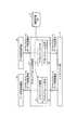
- FIG. 12is a diagram illustrating an outline of a flow of processing performed by the wireless communication apparatus according to the second embodiment.
- FIG. 13is a flowchart illustrating the flow of data transmission processing by the wireless communication apparatus according to the second embodiment.
- FIG. 14is a flowchart illustrating a flow of data reception processing performed by the wireless communication apparatus according to the second embodiment.
- FIG. 15is a diagram illustrating an example of an ad hoc header when the channel number is changed.
- FIG. 16is a diagram illustrating an example of a data flow when the channel number is changed.
- FIG. 17is a diagram illustrating a computer system 100 that executes a wireless communication program.
- FIG. 18is a diagram illustrating a conventional ad hoc network using a plurality of channels.
- FIG. 19is a diagram illustrating an example of occurrence of interference.
- FIG. 1is a diagram illustrating an overall configuration of an ad hoc network including a wireless communication device disclosed in the present application.
- an ad hoc networkhaving a node a, a node b, a node c, a node d, a node e, and a node Y is connected to a network server on the L3 network via a GW (GateWay).
- the wireless communication device disclosed in this applicationis a device corresponding to each node, and performs wireless communication with each node, GW, and network server using a 2.4 GHz band ISM (Industry Science Medical) band or the like.
- This wireless communication deviceis, for example, a device that is attached to a meter reading device such as electricity, water, or gas that is a terminal whose position is relatively fixed, and each node is a meter reading device to which a wireless communication device is attached. .
- Each such nodeperiodically transmits and receives a message (HELLO message) including node information such as route information and communication quality information of an inter-node link between adjacent nodes.
- HELLO messagea message
- Each nodecalculates the communication quality of each route obtained by sending and receiving the HELLO message, builds multiple routes to the final destination based on the result, determines the optimum route, and generates a routing table To do.
- each noderecalculates (updates) the communication quality of each route based on the actual data communication results and transmission / reception of HELLO messages with neighboring nodes, and maintains the route and learns the optimum route. Then, the routing table is changed as needed.
- GWis a network device that connects a wireless local area network (LAN) that is an ad hoc network and an L3 network that is an external network.
- LANwireless local area network
- L3 networkL3 network that is an external network.
- the GWhas functions such as protocol conversion, firewall, and firewall rule dynamic change, and also interconnects each node with a network server and the like by performing address conversion and data replacement.
- the network serveris connected to each node and is, for example, a management device that collects and manages the status of the ad hoc network, performance information, communication information, and the like of each node.
- a management devicethat collects and manages the status of the ad hoc network, performance information, communication information, and the like of each node.
- the number of nodes, the number of ad hoc networks, the number of servers connected to the L3 network, the example of the wireless communication device described above, and the like illustrated in FIG. 1are merely examples, and are not limited thereto.
- another ad hoc network or the likemay be connected to the L3 network.
- FIG. 2is a diagram illustrating an example in which a GW transmits a HELLO message to an adjacent node.
- the GWwhen the GW reaches the HELLO transmission timing, the GW broadcast-transmits a HELLO message including node information such as route information held by the own device and communication quality information of the inter-node link. Then, adjacent nodes a, b, and c receive the HELLO message from the GW. Note that, in the initial stage of ad hoc network construction, the node information transmitted from the GW is empty because it is before network construction.
- the nodes a, b, and c that have received the HELLO message from the GWregister the GW in a route information table (routing table) managed and held inside. Further, the nodes a, b, and c use the node information held by the GW included in the HELLO message received from the GW to calculate the route quality and the communication quality of the link between nodes, and the result is the routing table. And register in the link table. Note that the nodes a, b, and c do not rebroadcast the HELLO message received from the GW, in other words, do not perform flooding.
- the above routing tableis a table that stores “hop count (Hop), route quality weight (d), return link weight (E)” and the like as route information to the destination node.
- the link tablestores each information received by the HELLO message.
- the link tablestores a local transmission source address (LS), link quality information, the number of HELLO receptions, the HELLO request interval, and the like.
- FIG. 3is a diagram illustrating an example in which the node b transmits a HELLO message to an adjacent node.
- the node Y that has received the HELLO message from the node bregisters the node b in the routing table, calculates that the route to the GW is via the node b, and calculates the route quality and link quality. Register in the routing table and link table.
- the above-described processingis executed not only at the node Y but also at the nodes a to e and GW that have received the HELLO message from the node b, and is similarly executed at the node that has received the HELLO message from the node a or the node c. Is done.
- node Yreceives a HELLO message containing GW node information from each of nodes b, d, and e, and thus constructs a plurality of routes with nodes b, d, and e as the next transfer candidates as routes to GW. can do.
- the node Ydetermines a plurality of optimal routes to the GW as the final destination based on the route quality and link quality information in each route. Specifically, as shown in FIG. 4, the node Y has (1) node b-GW, (2) node b-node a-GW, and (3) node e-node c- as routes to the GW. Determine the 3 routes of GW.
- FIG. 4is a diagram illustrating an example of a confirmed route.
- each nodegenerates a route to the destination node as a routing table.
- FIG. 5is a diagram illustrating an example of the routing table generated at the node Y.
- the node Yincludes “GD, LD, Hop, d, E” as “GW, LD1, 2, 50, 20”, “GW, LD2, 3, 60, 30”, “GW, LD3, 3, 80, 50 "and the like are stored.
- GDstored here indicates a global destination address
- LDis a route number number for distinguishing a route to be managed
- Hopindicates the number of hops to GD.
- Dis a route quality weight obtained by quantifying the delay on the route to the GD
- Eis a communication quality weight from the partner node toward the own node.
- each nodetransmits and receives HELLO messages between the nodes, calculates the communication quality of each route, and builds a plurality of routes to the final destination and determines the optimum route based on the result.
- a routing tablecan be generated.
- each noderecalculates the communication quality of each route from the actual data communication results and the transmission / reception of HELLO messages with neighboring nodes regarding the constructed route, maintaining the route and learning the optimum route, Change the routing table as needed.
- FIG. 6is a diagram illustrating a format example of the HELLO message
- FIG. 7is a diagram illustrating a generation example of the HELLO message.
- the HELLO messagehas an ad hoc header, a compressed header, a HELLO message header, a plurality of HELLO headers, and a signature.
- the ad hoc headeris a header in which information necessary for a protocol layer (ad hoc layer) used in an ad hoc network is incorporated, and has a plurality of fields.
- the ad hoc headerhas fields called “local destination address (LD)” and “local source address (LS)” indicating a data transmission / reception destination.
- the ad hoc headerhas fields of “frame type” indicating the type of data frame transmitted and received between nodes and “frame size” indicating the size of the frame.
- the nodesince a HELLO message can be attached with a plurality of HELLO headers, the node has a function of compressing the HELLO message with a compression algorithm and transmitting it to an adjacent node, or expanding a received HELLO message.
- a compressed headerin which information necessary for compression / decompression of the frame is embedded is attached after the ad hoc header.
- the compressed headerhas fields of “compression type” indicating the compression method of the data portion (payload) after the compressed header and “frame size” indicating the size of the frame before compression. Each node device can appropriately decompress the payload in consideration of this compression type.
- the HELLO message headeris a header in which information necessary for transmitting / receiving node information (HELLO header) such as path information held by the own device between nodes and communication quality information of links between nodes is incorporated.
- HELLO headerinformation necessary for transmitting / receiving node information
- “number of hello headers”indicating the number of HELLO headers
- “device ID”indicating the ID of the node device
- “access key” for decrypting the information encrypted by the inter-node link Fieldis included.
- the HELLO messageensures the security of data sent and received between nodes and prevents spoofing by a third party.
- a data frame (payload) after the ad hoc headeris attached to a data frame transmitted / received between nodes, and the payload is encrypted using a common key and transmitted / received.
- the HELLO headerincludes a 6-byte global destination address (GD) area, a 1-byte node type / hop number area, a 1-byte reserved area, a 4-byte path quality weight (d) area, 4 bytes of return link weight (E).
- GDglobal destination address
- dpath quality weight
- Ereturn link weight
- the global destination address (GD) areais information indicating the final destination node, for example, the MAC address of the final destination node.
- the node type / hop count areaincludes GW information in which 1 is set when the global bus destination address is GW, and 0 when the global bus destination address is other than GW, and the hop count to the final destination node.
- the route quality weight (d)is a numerical value of the delay on the route to the global destination address.
- the return link weight (E)is communication quality weight from the partner node toward the own node, in other words, quality information indicating how much the HELLO message transmitted from the own device is received by the partner.
- GDglobal destination node
- A, B, C, Dthe global destination node
- three routesare stored for each GD.
- GDis “A”
- “LD, Hop, d, E”is “LD1, 5, 50, 20”, “LD2, 6, 60, 30”, “LD3, 4, 80, 50”.
- the node having the hop count less than the threshold among the optimum routes to each GDis written in the HELLO header and broadcast to the adjacent nodes. Send. For example, as illustrated in FIG. 7, the node writes “LD1” having the smallest “E” in the route having the GD “A” in the HELLO header (see (1) in FIG. 7). Similarly, the node writes “LD1” for “LD1” and “C” for the route whose GD is “B” (see (2) and (3) in FIG. 7).
- the nodedoes not write “LD1” having the smallest “E” among the routes having the GD “C” because the “Hop” is not less than the threshold “20” in the HELLO header. Thereafter, the node broadcasts the HELLO message generated in this way to the adjacent node.
- FIG. 8is a block diagram illustrating the configuration of the wireless communication apparatus according to the first embodiment.
- This wireless communication device 1is a device attached to a meter-reading device or the like corresponding to each node shown in FIG. 1 and the like, and includes a transmission unit 1a, a reception unit 1b, a determination unit 1c, and a reception control unit 1d. .
- the transmission unit 1atransmits communication data to the destination node using any one of a plurality of channels. For example, the transmission unit 1a assigns a channel number used by the communication data to an ad hoc header in an ad hoc message frame that is communication data of an application or the like, and transmits it to the destination.
- the receiving unit 1breceives the communication data addressed to the own node transmitted using any one of the plurality of channels. For example, the receiving unit 1b receives communication data addressed to itself from another node and outputs the data to the determining unit 1c.
- the determining unit 1cacquires channel information included in the communication data received by the receiving unit 1b, and determines whether or not the acquired channel information is channel information to be communicated. For example, the determination unit 1c determines whether or not the channel number included in the ad hoc header in the ad hoc message frame that is the received communication data is the channel number that the wireless communication device 1 is currently communicating with, and the result Is output to the reception control unit 1d.
- the reception control unit 1dperforms a reception process on the communication data received by the reception unit 1b when the determination unit 1c determines that the channel information is a communication target.
- the reception control unit 1ddiscards the communication data received by the reception unit 1b when the determination unit 1c determines that the channel information is not communication target.
- the wireless communication device on the communication data transmission sideadds the channel number used by the communication data to be transmitted and transmits it to the destination (reception side).
- the wireless communication device on the receiving sidereceives only when the channel number included in the received communication data is the channel number as the current target.
- the wireless communication device on the receiving sidecan receive only communication data transmitted with a normal channel number.
- the radio communication device on the receiving sidecan determine whether or not the data is to be received from the channel number included in the communication data even when interference occurs in the network. Therefore, the communication service can be normally used even in an ad hoc network environment where a plurality of channels can be used.
- the wireless communication device disclosed in the present applicationmay have various control units in addition to the control unit exemplified in the first embodiment. Therefore, in the second embodiment, a wireless communication apparatus having various control units other than the control unit exemplified in the first embodiment will be described with reference to FIGS.
- FIG. 9is a block diagram illustrating the configuration of the wireless communication apparatus according to the second embodiment.
- the wireless communication device 10includes an interface unit 11, a configuration definition DB 12, a link table 13, a routing table 14, and an ad hoc protocol processing unit 15. Further, the wireless communication device 10 includes a data reception processing unit 16, an application processing unit 17, and a data transmission processing unit 18.
- the configuration definition DB 12, the link table 13, and the routing table 14are semiconductor memory devices or storage devices such as hard disks.
- the ad hoc protocol processing unit 15, the data reception processing unit 16, the application processing unit 17, and the data transmission processing unit 18are integrated circuits, electronic circuits, and the like.
- the interface unit 11is a wireless communication interface that performs wireless communication with other wireless communication devices and GWs. For example, the interface unit 11 receives a HELLO message or normal communication data from another adjacent node, and outputs it to the ad hoc protocol processing unit 15. The interface unit 11 broadcasts the HELLO message received from the ad hoc protocol processing unit 15 to an adjacent node, or transmits the communication data received from the ad hoc protocol processing unit 15 to the destination node.
- the configuration definition DB 12is a storage unit that holds configuration information such as the communication status of the wireless communication device 10.
- the configuration definition DB 12stores the channel number used in the communication data in association with the type of communication data, and stores the wireless transmission signal output level value at the local point.
- the link table 13is a storage unit that holds information extracted from the received HELLO message by the data reception processing unit 16.
- the link table 13stores “local transmission source address (LS)”, “link quality information”, “HELLO reception count”, “HELLO request interval”, “access key”, and the like.
- the “local source address (LS)”is address information of the source node of the received HELLO message, and the “link quality information” is “path quality weight (d)” included in the received HELLO message. It is. Further, “HELLO reception count” indicates the number of HELLO messages received from the LS, and “HELLO request interval” indicates an interval of transmission / reception with the LS.
- the “access key”indicates an encryption key used when the frame type transmitted from the transmission source node combines encryption of data frames other than the HELLO message.
- the routing table 14is a storage unit that holds routing information up to the destination node. Specifically, the routing table 14 stores a predetermined number of routes as the optimum route among the plurality of routes to the destination node, for example, in ascending order of the communication quality weight “E”, that is, in descending order of communication quality.
- the routing table 14includes “GD, LD, Hop, d, E” as “GW, LD1, 2, 50, 20”, “GW, LD2, 3, 60” as routing information. , 30 ”,“ GW, LD3, 3, 80, 50 ”and the like.
- GDstored here indicates a global destination address
- LDis a route number number for distinguishing a route to be managed
- Hopindicates the number of hops to GD.
- Dis a route quality weight obtained by quantifying the delay on the route to the GD
- Eis a communication quality weight from the partner node toward the own node.
- the ad hoc protocol processing unit 15adds an ad hoc header to each data transmitted from the data transmission processing unit 18 and transmits the data to the destination, and outputs the data received by the interface unit 11 to the data reception processing unit 16. For example, when a HELLO message is input from the data transmission processing unit 18, the ad hoc protocol processing unit 15 adds an ad hoc header to the HELLO message and broadcasts to an adjacent node (another wireless communication device). .
- the ad hoc protocol processing unit 15refers to the configuration definition DB 12 and acquires a communication target channel number used by the type of the data. . Subsequently, the ad hoc protocol processing unit 15 adds an ad hoc header to which the channel number acquired from the configuration definition DB 12 is added to the input data, and transmits it to the destination node according to the routing information stored in the routing table 14. To do.
- the ad hoc protocol processing unit 15determines whether the data received by the interface unit 11 is the above-described HELLO message or communication data processed by an application or the like. Then, if the received data is a HELLO message, the ad hoc protocol processing unit 15 transfers the HELLO message to the data reception processing unit 16.
- the ad hoc protocol processing unit 15acquires channel information included in the communication data, and determines whether the acquired channel information is channel information to be communicated. . Specifically, the ad hoc protocol processing unit 15 acquires the type and channel number of the communication data from the ad hoc header of the received communication data. The ad hoc protocol processing unit 15 stores the combination of the acquired communication data type and channel number in the configuration definition DB 12, that is, the received communication data is data transmitted with the channel number to be communicated. It is determined whether.
- the ad hoc protocol processing unit 15outputs the communication data to the data reception processing unit 16 when it is determined that it is channel information to be communicated, that is, data transmitted with a normal channel number.
- the ad hoc protocol processing unit 15discards the received communication data when it is determined that the data is not the channel number to be communicated, that is, the data is not transmitted with a normal channel number.
- the data reception processing unit 16performs various reception processes on the data output from the ad hoc protocol processing unit 15. For example, when the data output from the ad hoc protocol processing unit 15 is communication data, the data reception processing unit 16 is received by the application processing unit 17 that executes an application or the like that processes the communication data. Output communication data.
- the data reception processing unit 16when the data output from the ad hoc protocol processing unit 15 is a HELLO message, the data reception processing unit 16 generates and updates the link table 13 and the routing table 14. Specifically, the data reception processing unit 16 refers to the “local transmission source address (LS)” in the link table 13 to determine whether or not the received HELLO message is transmitted from a new transmission source node. Judgment. Then, the data reception processing unit 16 generates a new table in the link table 13 when it is transmitted from a new transmission source node. That is, the data reception processing unit 16 extracts or generates “LS, link quality information, HELLO reception count, HELLO request interval, access key” from the HELLO message, and stores the extracted data in the link table 13.
- LSlocal transmission source address
- the data reception processing unit 16updates the link table 13 when it is not transmitted from a new transmission source node but transmitted from an existing node. That is, the data reception processing unit 16 acquires “LS, link quality information, HELLO reception count, HELLO request interval, access key” from the received HELLO message, and updates the corresponding “LS” table.
- the data reception processing unit 16performs routing including “GD, LD, Hop, d, E” from the information stored in the link table 13. Information is generated and stored in the routing table 14.
- the application processing unit 17executes programs and applications, and transmits generated data and the like to other nodes and other networks. For example, the application processing unit 17 outputs data generated by an application process executed using an upper protocol layer such as an application layer or a presentation layer to the data transmission processing unit 18. In addition, when the application processing unit 17 receives communication data from the data reception processing unit 16, the application processing unit 17 executes an application or the like that processes the communication data, and transmits new data generated based on the execution result to the destination or displays the execution result. Or stored in a storage unit (not shown).
- the data transmission processing unit 18When the HELLO message timing is reached, the data transmission processing unit 18 generates a HELLO message and outputs it to the ad hoc protocol processing unit 15. For example, the data transmission processing unit 18 stores the node information stored in the self apparatus in the HELLO header in an ad hoc header, a compressed header, a HEELO message header, a plurality of HELLO headers, and a signature included in the HELLO message. Specifically, as described in FIG. 7, the data transmission processing unit 18 stores optimum route information for each global destination node (GD) stored in the routing table 14 in each of the plurality of HELLO headers. Then, the data transmission processing unit 18 generates a HELLO message including a HELLO header to which node information is added for each global destination node (GD) and outputs the HELLO message to the ad hoc protocol processing unit 15.
- GDglobal destination node
- the data transmission processing unit 18outputs an ad hoc frame data transmission request for requesting addition of an ad hoc header to the ad hoc protocol processing unit 15 together with the communication data.
- FIG. 10is a diagram illustrating a detailed configuration of the ad hoc protocol processing unit
- FIG. 11is a diagram illustrating a format example of ad hoc frame data.
- the ad hoc protocol processing unit 15when receiving the ad hoc frame data transmission request from the data transmission processing unit 18, the ad hoc protocol processing unit 15 generates ad hoc frame data in which an ad hoc header is added to the received data ((1 in FIG. 10). )reference). At this time, the ad hoc protocol processing unit 15 acquires the channel number used by the communication data (ad hoc frame data) included in the received request from the configuration definition DB 12, and adds the acquired channel number to the ad hoc header.
- the ad hoc protocol processing unit 15in the “free” area of the ad hoc header having “local destination address, local source address, group ID, frame type, free, frame length”, A channel number (CH number) is added.
- This “local destination address”is information such as the MAC (Media Access Control) address that identifies the destination node of ad hoc frame data, and the “local source address” identifies the source node, that is, its own device. Information such as a MAC address to be performed.
- the “group ID”is identifier information for grouping nodes constituting the ad hoc network for each area such as a municipality. This “group ID” is used for purposes such as grouping control of an ad hoc network so that only nodes having the same “group ID” can communicate with each other.
- the frame typeindicates the type of ad hoc message frame to be transmitted. For example, the data type of the payload portion after the ad hoc header is shown, such as a HELLO message when the frame type is “1” and communication data when the frame type is “2”. “Frame length” indicates the length of ad hoc frame data to be transmitted.
- the ad hoc protocol processing unit 15generates ad hoc frame data in which an ad hoc header is added to the data received from the data transmission processing unit 18, and transmits the data to the destination node via the interface unit 11 ((2) in FIG. 10). reference).
- the ad hoc protocol processing unit 15receives the ad hoc frame data from the interface unit 11 together with a reception notification (see (3) in FIG. 10). Then, the ad hoc protocol processing unit 15 acquires a channel number from the ad hoc header of the received data. Subsequently, the ad hoc protocol processing unit 15 outputs the acquired channel number to the data reception processing unit 16 if the acquired channel number is a communication target channel number, and discards it if it is not the communication target channel number ((( 4)).
- the ad hoc protocol processing unit 15acquires the channel number from the ad hoc header of the received data, and determines the type of the data from the ad hoc header of the data. Subsequently, the ad hoc protocol processing unit 15 acquires the channel number corresponding to the type of received data from the configuration definition DB 12, and the channel number acquired from the configuration definition DB 12 matches the channel number acquired directly from the data. It is determined whether or not. If both match, the ad hoc protocol processing unit 15 determines that the channel number is a communication target, and outputs the data to the data reception processing unit 16; otherwise, it is not a communication target channel number. And the data is discarded.
- FIG. 12is a diagram illustrating an outline of a process flow performed by the wireless communication apparatus according to the second embodiment.
- FIG. 13is a flowchart illustrating a data transmission process performed by the wireless communication apparatus according to the second embodiment.
- FIG. 14is a flowchart illustrating a data reception process performed by the wireless communication apparatus according to the second embodiment.
- the ad hoc protocol processing unit 15adds a use channel to an ad hoc header processed by the ad hoc protocol among the ad hoc frame data to be transmitted. Further, in the wireless communication device 10 on the data transmission side, the interface unit 11 adds an Ethernet header processed by the Ethernet protocol to the ad hoc frame data to be transmitted, and transmits the data to the destination by wireless communication.
- the ad hoc protocol processing unit 15acquires a channel number from the ad hoc header of the received ad hoc frame data, and determines whether or not the channel number is a communication target. .
- the ad hoc protocol processing unit 15determines that the channel number of the received data is the channel number to be communicated, the data is output to the data reception processing unit 16. .
- the ad hoc protocol processing unit 15 of the wireless communication device 10 on the data receiving sidediscards the data when it is determined that the channel number of the received data is not the channel number to be communicated.
- the ad hoc protocol processing unit 15generates data in which the channel number is added to the ad hoc header of the ad hoc frame data to be transmitted (step S102). Subsequently, the ad hoc protocol processing unit 15 stores the generated data in the routing table 14. According to the stored routing information, it is transmitted to the destination (step S103).
- the interface unit 11 of the wireless communication device 10receives ad hoc frame data addressed to itself (Yes in step S201). Then, the ad hoc protocol processing unit 15 determines whether or not a channel number is added to the ad hoc header of the received ad hoc frame data (step S202).
- the ad hoc protocol processing unit 15acquires the channel number from the ad hoc header (Step S203) and determines whether or not the channel number matches the communication target channel number. (Step S204). Subsequently, when the channel number acquired from the ad hoc header matches the channel number to be communicated (Yes at Step S204), the ad hoc protocol processing unit 15 outputs the data to the data reception processing unit 16 (Step S205). Thereafter, reception processing is executed by the data reception processing unit 16 and the application processing unit 17.
- the ad hoc protocol processing unit 15discards the received data (Step S206).
- Example 1Although the channel number was given to the ad hoc header and the example which can use a service normally also in an interference environment was demonstrated, besides this, for example, using an ad hoc header, It is also possible to change the channel number being used. Therefore, in the third embodiment, an example in which the channel number being used is changed using the ad hoc header of the ad hoc frame data will be described with reference to FIGS. 15 and 16.
- FIG. 15is a diagram illustrating an example of an ad hoc header when the channel number is changed
- FIG. 16is a diagram illustrating an example of a data flow when the channel number is changed.
- a management server or the likethat manages channel numbers or acquires and manages various types of information from nodes, as shown in FIG. 15, changes channel numbers (CH numbers) and change instructions (CH (Number change instruction) is added and the ad hoc header is expanded and transmitted to the destination.
- CH numberschannel numbers
- CHNumberer change instruction
- the channel numbercan be changed using ad hoc frame data.
- a node of a water meter meterwhich is the first lifeline, fails due to a disaster, and an event in which water supply cannot be used occurs due to the failure of this node.
- the channel numberis changed by the method described above so that the water meter meter and the water supply can be used.
- Channel informationFor example, in the first to third embodiments, the example in which the channel number is used as the channel information has been described. However, the present invention is not limited to this example.
- the channelcan be specified such as a uniquely assigned serial number. Any information may be used.
- the reception control for receiving only the data with the channel number to be communicated among the communication data with the channel number and the communication data with the channel number to be communicated as the destinationA wireless communication apparatus having transmission control to transmit to has been described.
- the wireless communication apparatusdoes not necessarily have both controls, and may be configured to have only one of them.
- each component of each illustrated apparatusis functionally conceptual, and does not necessarily need to be physically configured as illustrated. That is, for example, the specific form of distribution / integration of each device such as integrating the data reception processing unit 16 and the data transmission processing unit 18 is not limited to that shown in the figure, and all or a part thereof may be used for various loads and usage conditions. Depending on the above, it can be configured to be functionally or physically distributed and integrated in arbitrary units. Further, all or any part of each processing function performed in each device may be realized by a CPU and a program analyzed and executed by the CPU, or may be realized as hardware by wired logic.
- programBy the way, the various processes described in the above embodiments can be realized by executing a program prepared in advance on a computer system such as a personal computer or a workstation. Therefore, in the following, an example of a computer system that executes a program having the same function as in the above embodiment will be described.
- FIG. 17is a diagram illustrating a computer system 100 that executes a wireless communication program.
- the computer system 100includes a RAM 101, an HDD 102, a ROM 103, and a CPU 104.
- the ROM 103stores in advance a program that exhibits the same function as in the above embodiment. That is, as shown in FIG. 17, an application processing program 103a, a data transmission processing program 103b, an ad hoc protocol processing program 103c, and a data reception processing program 103d are stored in advance.
- the CPU 104reads out and executes these programs 103a to 103d, whereby each process is performed as shown in FIG. That is, the application process 104a, the data transmission process 104b, the ad hoc protocol process 104c, and the data reception process 104d.
- the application processing process 104acorresponds to the application processing unit 17 shown in FIG. 9, and similarly, the data transmission processing process 104b corresponds to the data transmission processing unit 18.
- the ad hoc protocol processing process 104 ccorresponds to the ad hoc protocol processing unit 15, and the data reception processing process 104 d corresponds to the data reception processing unit 16.
- the HDD 102is provided with a configuration definition table 102a, a link table 102b, and a routing table 102c.
- the configuration definition table 102acorresponds to the configuration definition table 12 shown in FIG. 9, the link table 102b corresponds to the link table 13, and the routing table 102c corresponds to the routing table 14.
- the above-described programs 103 a to 103 dare not necessarily stored in the ROM 103.
- a “portable physical medium”such as a flexible disk (FD), a CD-ROM, a DVD disk, a magneto-optical disk, or an IC card inserted into the computer system 100.
- a “fixed physical medium”such as a hard disk drive (HDD) provided inside or outside the computer system 100.
- HDDhard disk drive
- itmay be stored in “another computer system” connected to the computer system 100 via a public line, the Internet, a LAN, a WAN, or the like. Then, the computer system 100 may read and execute the program from these.
- the program referred to in the other embodimentsis recorded in a computer-readable manner on a recording medium such as the above-mentioned “portable physical medium”, “fixed physical medium”, “communication medium”, and the like. . Then, the computer system 100 realizes the same function as the above-described embodiment by reading and executing the program from such a recording medium. Note that the program referred to in the other embodiments is not limited to being executed by the computer system 100. For example, the present invention can be similarly applied to a case where another computer system or server executes a program or a case where these programs cooperate to execute a program.
Landscapes
- Engineering & Computer Science (AREA)
- Computer Networks & Wireless Communication (AREA)
- Signal Processing (AREA)
- Quality & Reliability (AREA)
- Mobile Radio Communication Systems (AREA)
Abstract
Description
Translated fromJapanese本発明は、無線通信装置および無線通信プログラムに関する。The present invention relates to a wireless communication apparatus and a wireless communication program.
近年、無線LAN(Local Access Network)のアクセスポイントなどのネットワークインフラを用いずに、端末同士が接続してネットワークを構築するアドホックネットワークが利用されている。In recent years, ad hoc networks have been used in which terminals are connected to construct a network without using a network infrastructure such as a wireless LAN (Local Access Network) access point.
アドホックネットワークで利用されるプロトコルとしては、IETF(Internet Engineering Task Force)のMANET WG(Mobile Adhoc Networks Working Group)で検討されているリアクティブ型やプロアクティブ型のプロトコルがある。例えば、リアクティブ型のプロトコルとしては、AODV(Adhoc On-Demand Distance Vector)が代表的なプロトコルであり、プロアクティブ型としては、OLSR(Optimized Link State Routing)が代表的なプロトコルである。Protocols used in ad hoc networks include reactive and proactive protocols that are being studied by the Internet Engineering Task Force (IETF) MANET WG (Mobile Adhoc Networks Working Group). For example, AODV (Adhoc On-Demand Distance Vector) is a typical protocol as a reactive protocol, and OLSR (Optimized Link State Routing) is a typical protocol as a proactive type.
このようなアドホックネットワークに各ノードは、隣接する他ノードとメッセージを交換して隣接ノードの死活状況を検出し、ルーティングテーブルを作成する。そして、各ノードは、このようにして作成したルーティングテーブルを用いて、通信データの転送制御を実施する。Each node in such an ad hoc network exchanges messages with other adjacent nodes to detect the alive status of the adjacent nodes and creates a routing table. Each node performs communication data transfer control using the routing table created in this way.
そして、アドホックネットワークのノード間の無線LANでは、2.4GHz帯のISM(Industry Science Medical)バンドで使用可能な14チャネルの内の1つのチャネルが使用されている。複数チャネルを使用した無線LANでは、例えば、送信元から送信先に通信データを送信する場合に、各ノードが持つ複数のチャネルに渡って形成されるパスを用いるか、2つ以上のパスに同じデータを送信することで、信頼性を向上させる技術が開示されている。In a wireless LAN between nodes of an ad hoc network, one of 14 channels that can be used in an ISM (Industry Science Medical) band in the 2.4 GHz band is used. In a wireless LAN using a plurality of channels, for example, when transmitting communication data from a transmission source to a transmission destination, a path formed over a plurality of channels of each node is used, or the same for two or more paths A technique for improving reliability by transmitting data is disclosed.
しかしながら、上述した技術では、各チャネルは周波数帯の一部が重複しているため、電波の干渉が生じ易く、混信が発生して、通信サービスが正常に利用できない事象が発生するという課題があった。However, the above-described technology has a problem in that since each channel has a part of the frequency band overlapping, radio wave interference is likely to occur, interference occurs, and an event that the communication service cannot be normally used occurs. It was.
上述した課題を図18と図19とを例示して具体的に説明する。図18は、近接するチャネルの事例を示す図であり、図19は、混信の発生事例を示す図である。図18に示すように、GW、ノードA、ノードB、ノードC、ノードD、ノードE、ノードFを有するアドホックネットワークは、X(CH14)、Y(CH11)、Z(CH5)の3チャネルで接続されている。なお、ここでX、Y、Zとは、チャネルで通信対象とするデータ種別を示しており、例えば、各ノードが検針装置である場合には電気、水道、ガスなどが該当する。The above-described problem will be specifically described with reference to FIG. 18 and FIG. 18 is a diagram illustrating an example of adjacent channels, and FIG. 19 is a diagram illustrating an example of occurrence of interference. As shown in FIG. 18, an ad hoc network having GW, node A, node B, node C, node D, node E, and node F has three channels of X (CH14), Y (CH11), and Z (CH5). It is connected. Here, X, Y, and Z indicate data types to be communicated through the channel. For example, when each node is a meter-reading device, electricity, water, gas, and the like are applicable.
この場合、各ノードは、CH14で通信したい状況であっても、各チャネルは周波数帯の一部が重複しているため、別のチャネルの通信を受信してしまう。このため、図19に示すように、ノードが同一であるが、チャネル別に異なる通信サービスを行う場合に、チャネル間で混信が生じ、通信サービスが正常に利用できなくなる。In this case, even if each node wants to communicate with CH14, each channel receives a communication of another channel because a part of the frequency band overlaps. For this reason, as shown in FIG. 19, when the nodes are the same but different communication services are provided for each channel, interference occurs between the channels, and the communication service cannot be normally used.
開示の技術は、上記に鑑みてなされたものであって、複数チャネルが利用可能なアドホックネットワーク環境においても、通信サービスを正常に利用することが可能である無線通信装置および無線通信プログラムを提供することを目的とする。The disclosed technology has been made in view of the above, and provides a wireless communication apparatus and a wireless communication program that can normally use a communication service even in an ad hoc network environment in which a plurality of channels can be used. For the purpose.
上述した課題を解決し、目的を達成するために、本発明は、複数のチャネルのうちいずれかのチャネルを用いて、宛先ノードに通信データを送信する送信部と、前記複数のチャネルのうちいずれかのチャネルを用いて送信された自ノード宛の通信データを受信する受信部と、前記受信部によって受信された通信データに含まれるチャネル情報を取得し、取得されたチャネル情報が通信対象のチャネル情報であるか否かを判定する判定部と、前記判定部によって通信対象のチャネル情報であると判定された場合に、前記受信部によって受信された通信データに対して受信処理を実施し、前記判定部によって通信対象のチャネル情報でないと判定された場合に、前記受信された通信データを破棄する受信制御部とを有する。In order to solve the above-described problems and achieve the object, the present invention provides a transmission unit that transmits communication data to a destination node using any one of a plurality of channels, and any one of the plurality of channels. A receiving unit for receiving communication data addressed to the own node transmitted using the channel, channel information included in the communication data received by the receiving unit is acquired, and the acquired channel information is a channel to be communicated A determination unit that determines whether the information is information, and when the determination unit determines that the channel information is to be communicated, a reception process is performed on the communication data received by the reception unit, A reception control unit that discards the received communication data when the determination unit determines that the channel information is not to be communicated.
また、本発明は、複数のチャネルのうちいずれかのチャネルを用いて、宛先ノードに通信データを送信する送信部と、前記複数のチャネルのうちいずれかのチャネルを用いて送信された自ノード宛の通信データを受信する受信部とを有し、前記送信部は、前記通信データに通信対象のチャネル情報を付加して、前記宛先ノードに通信データを送信する。In addition, the present invention provides a transmitter that transmits communication data to a destination node using any one of a plurality of channels, and is addressed to the own node that is transmitted using any one of the plurality of channels. The communication unit adds communication target channel information to the communication data, and transmits the communication data to the destination node.
本発明にかかる無線通信装置および無線通信プログラムは、複数チャネルが利用可能なアドホックネットワーク環境においても、通信サービスを正常に利用することが可能であるという効果を奏する。The wireless communication device and the wireless communication program according to the present invention have an effect that the communication service can be normally used even in an ad hoc network environment where a plurality of channels can be used.
以下に、本発明にかかる無線通信装置および無線通信プログラムの実施例を図面に基づいて詳細に説明する。なお、この実施例によりこの発明が限定されるものではない。Hereinafter, embodiments of a wireless communication apparatus and a wireless communication program according to the present invention will be described in detail with reference to the drawings. Note that the present invention is not limited to the embodiments.
[全体構成]
まず、図1を用いて、本願が開示する無線通信装置を含むアドホックネットワークの全体構成を説明する。図1は、本願が開示する無線通信装置を含むアドホックネットワークの全体構成を示す図である。図1に示すように、ノードa、ノードb、ノードc、ノードd、ノードe、ノードYを有するアドホックネットワークが、GW(GateWay)を介してL3ネットワーク上のネットワークサーバに接続される。[overall structure]
First, the overall configuration of an ad hoc network including a wireless communication device disclosed in the present application will be described with reference to FIG. FIG. 1 is a diagram illustrating an overall configuration of an ad hoc network including a wireless communication device disclosed in the present application. As shown in FIG. 1, an ad hoc network having a node a, a node b, a node c, a node d, a node e, and a node Y is connected to a network server on the L3 network via a GW (GateWay).
本願が開示する無線通信装置は、各ノードに対応する装置であり、2.4GHz帯のISM(Industry Science Medical)バンド等を使用して、各ノード、GWおよびネットワークサーバと無線通信を行う。この無線通信装置は、例えば、位置が比較的固定された端末である電気、水道、ガスなどの検針装置に取り付けられる装置であり、各ノードは、無線通信装置が取り付けられた検針装置などである。The wireless communication device disclosed in this application is a device corresponding to each node, and performs wireless communication with each node, GW, and network server using a 2.4 GHz band ISM (Industry Science Medical) band or the like. This wireless communication device is, for example, a device that is attached to a meter reading device such as electricity, water, or gas that is a terminal whose position is relatively fixed, and each node is a meter reading device to which a wireless communication device is attached. .
このような各ノードは、隣接するノードとの間で経路情報やノード間リンクの通信品質情報などのノード情報を含むメッセージ(HELLOメッセージ)の送受信を定期的に行う。そして、各ノードは、HELLOメッセージの送受信で得られた各経路の通信品質を計算し、その結果に基づいて最終宛先までの経路を複数構築し、最適な経路の確定を行ってルーティングテーブルを生成する。また、各ノードは、構築した経路に関して、実際のデータ通信の実績や隣接ノードとのHELLOメッセージの送受信から、各経路の通信品質を再計算(更新)し、経路の維持や最適経路の学習をして、ルーティングテーブルの随時変更を行う。Each such node periodically transmits and receives a message (HELLO message) including node information such as route information and communication quality information of an inter-node link between adjacent nodes. Each node calculates the communication quality of each route obtained by sending and receiving the HELLO message, builds multiple routes to the final destination based on the result, determines the optimum route, and generates a routing table To do. In addition, each node recalculates (updates) the communication quality of each route based on the actual data communication results and transmission / reception of HELLO messages with neighboring nodes, and maintains the route and learns the optimum route. Then, the routing table is changed as needed.
GWは、アドホックネットワークである無線LAN(Local Area Network)と、外部ネットワークであるL3ネットワークとを接続するネットワーク機器である。例えば、GWは、プロトコル変換、ファイアウォール、ファイアウォールのルール動的変更などの機能を有するとともに、アドレス変換やデータの載せ換えなどを行うことにより、各ノードとネットワークサーバ等を相互接続する。GW is a network device that connects a wireless local area network (LAN) that is an ad hoc network and an L3 network that is an external network. For example, the GW has functions such as protocol conversion, firewall, and firewall rule dynamic change, and also interconnects each node with a network server and the like by performing address conversion and data replacement.
ネットワークサーバは、各ノードと相互に接続され、例えば、アドホックネットワークの状況、各ノードの性能情報や通信情報等を収集して管理する管理装置などである。なお、図1に示したノードの数、アドホックネットワークの数、L3ネットワークに接続されるサーバの数、上述した無線通信装置の例などは、あくまで例示であり、これに限定されるものではない。例えば、L3ネットワークには、他のアドホックネットワーク等が接続されていてもよい。The network server is connected to each node and is, for example, a management device that collects and manages the status of the ad hoc network, performance information, communication information, and the like of each node. Note that the number of nodes, the number of ad hoc networks, the number of servers connected to the L3 network, the example of the wireless communication device described above, and the like illustrated in FIG. 1 are merely examples, and are not limited thereto. For example, another ad hoc network or the like may be connected to the L3 network.
[アドホックネットワークの構築例]
次に、図2~図7を用いて、各ノードがHELLOメッセージをやり取りすることで、図1に示したアドホックネットワークが自動的に構築する例について説明する。図2は、GWが隣接ノードにHELLOメッセージを送信する例を示す図である。[Ad hoc network configuration example]
Next, an example in which the ad hoc network shown in FIG. 1 is automatically constructed by exchanging HELLO messages between nodes will be described with reference to FIGS. FIG. 2 is a diagram illustrating an example in which a GW transmits a HELLO message to an adjacent node.
図2に示すように、GWは、HELLO送信タイミングに到達すると、自装置が保持する経路情報やノード間リンクの通信品質情報などのノード情報を含むHELLOメッセージをブロードキャスト送信する。そして、隣接するノードa、b、cは、GWからのHELLOメッセージを受信する。なお、アドホックネットワーク構築初期において、GWから送信されるノード情報は、ネットワーク構築前であることから空の状態である。As shown in FIG. 2, when the GW reaches the HELLO transmission timing, the GW broadcast-transmits a HELLO message including node information such as route information held by the own device and communication quality information of the inter-node link. Then, adjacent nodes a, b, and c receive the HELLO message from the GW. Note that, in the initial stage of ad hoc network construction, the node information transmitted from the GW is empty because it is before network construction.
続いて、GWからのHELLOメッセージを受信したノードa、b、cは、内部に管理・保持する経路情報テーブル(ルーティングテーブル)にGWを登録する。さらに、ノードa、b、cは、GWから受信したHELLOメッセージに含まれたGWが保持しているノード情報を使用して経路品質やノード間リンクの通信品質を計算し、その結果をルーティングテーブルやリンクテーブルに登録する。尚、ノードa、b、cは、GWから受信したHELLOメッセージの再ブロードキャスト、言い換えると、フラッディングは行わない。Subsequently, the nodes a, b, and c that have received the HELLO message from the GW register the GW in a route information table (routing table) managed and held inside. Further, the nodes a, b, and c use the node information held by the GW included in the HELLO message received from the GW to calculate the route quality and the communication quality of the link between nodes, and the result is the routing table. And register in the link table. Note that the nodes a, b, and c do not rebroadcast the HELLO message received from the GW, in other words, do not perform flooding.
上記ルーティングテーブルとは、宛先ノードまでの経路情報として、「ホップ数(Hop)、経路品質重み(d)、復路リンク重み(E)」などを記憶するテーブルである。また、リンクテーブルとは、HELLOメッセージで受信した各情報を記憶するものであり、例えば、ローカル送信元アドレス(LS)、リンク品質情報、HELLO受信回数、HELLO要求間隔などを記憶するテーブルである。The above routing table is a table that stores “hop count (Hop), route quality weight (d), return link weight (E)” and the like as route information to the destination node. The link table stores each information received by the HELLO message. For example, the link table stores a local transmission source address (LS), link quality information, the number of HELLO receptions, the HELLO request interval, and the like.
次に、図3に示すように、ノードbは、HELLO送信タイミングに到達すると、自装置が保持するノード情報を含むHELLOメッセージをブロードキャスト送信する。このノードbのHELLOメッセージには、ノードbのノード情報の他に、GWなど他のノード情報が含まれる。また、上述した処理は、ノードbだけでなく、GWからのHELLOメッセージを受信したノードa、ノードcでも実行される。なお、図3は、ノードbが隣接ノードにHELLOメッセージを送信する例を示す図である。Next, as shown in FIG. 3, when the node b reaches the HELLO transmission timing, the node b broadcasts a HELLO message including node information held by the own device. The HELLO message of node b includes other node information such as GW in addition to the node information of node b. The above-described processing is executed not only at the node b but also at the nodes a and c that have received the HELLO message from the GW. FIG. 3 is a diagram illustrating an example in which the node b transmits a HELLO message to an adjacent node.
続いて、ノードbからのHELLOメッセージを受信したノードYは、ノードbをルーティングテーブルに登録すると共に、GW宛の経路がノードb経由であることと、その経路品質やリンク品質を計算した結果をルーティングテーブルやリンクテーブルに登録する。また、上述した処理は、ノードYだけでなく、ノードbからのHELLOメッセージを受信したノードa~ノードeおよびGWでも実行され、ノードaやノードcからのHELLOメッセージを受信したノードでも同様に実行される。Subsequently, the node Y that has received the HELLO message from the node b registers the node b in the routing table, calculates that the route to the GW is via the node b, and calculates the route quality and link quality. Register in the routing table and link table. The above-described processing is executed not only at the node Y but also at the nodes a to e and GW that have received the HELLO message from the node b, and is similarly executed at the node that has received the HELLO message from the node a or the node c. Is done.
さらに、ノードdおよびノードeも、ノードbと同様に、それぞれのHELLO送信タイミングでHELLOメッセージをブロードキャスト送信する。したがって、ノードYでは、ノードb、d、e各々からGWのノード情報を含むHELLOメッセージを受信するので、GW宛ての経路としてノードb、d、eをそれぞれ次転送候補とする複数の経路を構築することができる。Further, similarly to the node b, the node d and the node e also broadcast the HELLO message at the respective HELLO transmission timing. Therefore, node Y receives a HELLO message containing GW node information from each of nodes b, d, and e, and thus constructs a plurality of routes with nodes b, d, and e as the next transfer candidates as routes to GW. can do.
その後、ノードYは、各経路での経路品質やリンク品質情報に基づいて、最終宛先であるGWまでの最適経路を複数確定する。具体的には、図4に示すように、ノードYは、GW宛の経路として、(1)ノードb-GW、(2)ノードb-ノードa-GW、(3)ノードe-ノードc-GWの3経路を確定する。なお、図4は、確定した経路の例を示す図である。After that, the node Y determines a plurality of optimal routes to the GW as the final destination based on the route quality and link quality information in each route. Specifically, as shown in FIG. 4, the node Y has (1) node b-GW, (2) node b-node a-GW, and (3) node e-node c- as routes to the GW. Determine the 3 routes of GW. FIG. 4 is a diagram illustrating an example of a confirmed route.
このようにして、各ノードは、宛先ノードまでの経路をルーティングテーブルとして生成する。ここで、ノードYで生成されるルーティングテーブルの例について、図5を用いて説明する。図5は、ノードYで生成されたルーティングテーブルの例を示す図である。図5に示すように、ノードYは、「GD、LD、Hop、d、E」として「GW、LD1、2、50、20」、「GW、LD2、3、60、30」、「GW、LD3、3、80、50」などと記憶する。In this way, each node generates a route to the destination node as a routing table. Here, an example of the routing table generated at the node Y will be described with reference to FIG. FIG. 5 is a diagram illustrating an example of the routing table generated at the node Y. As illustrated in FIG. 5, the node Y includes “GD, LD, Hop, d, E” as “GW, LD1, 2, 50, 20”, “GW, LD2, 3, 60, 30”, “GW, LD3, 3, 80, 50 "and the like are stored.
ここで記憶される「GD」とは、グローバル宛先アドレスを示しており、「LD」とは、管理する経路を区別する経路数番号であり、「Hop」とは、GDまでのホップ数を示している。また、「d」とは、GDまでの経路上での遅延を数値化した経路品質重みであり、「E」とは、相手ノードから自ノード方向への通信品質重みである。“GD” stored here indicates a global destination address, “LD” is a route number number for distinguishing a route to be managed, and “Hop” indicates the number of hops to GD. ing. “D” is a route quality weight obtained by quantifying the delay on the route to the GD, and “E” is a communication quality weight from the partner node toward the own node.
このように、各ノードは、各ノード間でHELLOメッセージを送受信し、各経路の通信品質を計算し、その結果をもって最終宛先までの複数の経路の構築及び最適な経路の確定を実施することで、ルーティングテーブルを生成することができる。また、各ノードは、構築した経路に関して、実際のデータ通信の実績や隣接ノードとのHELLOメッセージの送受信から、各経路の通信品質を再計算し、経路の維持や最適経路の学習をして、ルーティングテーブルの随時変更を行う。In this way, each node transmits and receives HELLO messages between the nodes, calculates the communication quality of each route, and builds a plurality of routes to the final destination and determines the optimum route based on the result. A routing table can be generated. In addition, each node recalculates the communication quality of each route from the actual data communication results and the transmission / reception of HELLO messages with neighboring nodes regarding the constructed route, maintaining the route and learning the optimum route, Change the routing table as needed.
[HELLOメッセージ]
次に、図6と図7を用いて、上述したアドホックネットワークの構築およびルーティングテーブルの生成において、各ノードの間で送受信されるHELLOメッセージについて説明する。図6は、HELLOメッセージのフォーマット例を示す図であり、図7は、HELLOメッセージの生成例を示す図である。[HELLO message]
Next, HELLO messages transmitted and received between the nodes in the above-described ad hoc network construction and routing table generation will be described with reference to FIGS. 6 and 7. FIG. 6 is a diagram illustrating a format example of the HELLO message, and FIG. 7 is a diagram illustrating a generation example of the HELLO message.
(フレームフォーマット)
まず、図6を用いて、HELLOメッセージのフォーマット例を説明する。図6に示すように、HELLOメッセージは、アドホックヘッダ、圧縮ヘッダ、HELLOメッセージヘッダ、複数のHELLOヘッダ、署名を有している。(Frame format)
First, a format example of the HELLO message will be described with reference to FIG. As shown in FIG. 6, the HELLO message has an ad hoc header, a compressed header, a HELLO message header, a plurality of HELLO headers, and a signature.
アドホックヘッダは、アドホックネットワークで利用するプロトコル層(アドホックレイヤー)で必要とする情報が組み込まれたヘッダであり、複数のフィールドを有している。例えば、アドホックヘッダは、データ送受信先を示す「ローカル宛先アドレス(LD)」や「ローカル差出アドレス(LS)」いうフィールドを有している。また、アドホックヘッダは、ノード間で送受信するデータフレームの種別を表す「フレームタイプ」と、フレームのサイズを表す「フレームサイズ」というフィールドを有している。The ad hoc header is a header in which information necessary for a protocol layer (ad hoc layer) used in an ad hoc network is incorporated, and has a plurality of fields. For example, the ad hoc header has fields called “local destination address (LD)” and “local source address (LS)” indicating a data transmission / reception destination. The ad hoc header has fields of “frame type” indicating the type of data frame transmitted and received between nodes and “frame size” indicating the size of the frame.
また、HELLOメッセージは、複数のHELLOヘッダを付けることが可能であるため、ノードはHELLOメッセージを圧縮アルゴリズムで圧縮して隣接ノードに送信、あるいは、受信したHELLOメッセージを伸張する機能を有している。例えば、ノード間で送受信するデータフレームがHELLOメッセージである場合、フレームの圧縮・伸張で必要とする情報が組み込まれた圧縮ヘッダがアドホックヘッダの後ろに付く。圧縮ヘッダは、圧縮ヘッダ以降のデータ部分(ペイロード)の圧縮手法を示す「圧縮タイプ」と、圧縮前のフレームのサイズを表す「フレームサイズ」というフィールドを有している。各ノード装置は、この圧縮タイプを考慮して、適切にペイロードの伸張を行うことができる。In addition, since a HELLO message can be attached with a plurality of HELLO headers, the node has a function of compressing the HELLO message with a compression algorithm and transmitting it to an adjacent node, or expanding a received HELLO message. . For example, when a data frame transmitted / received between nodes is a HELLO message, a compressed header in which information necessary for compression / decompression of the frame is embedded is attached after the ad hoc header. The compressed header has fields of “compression type” indicating the compression method of the data portion (payload) after the compressed header and “frame size” indicating the size of the frame before compression. Each node device can appropriately decompress the payload in consideration of this compression type.
HELLOメッセージヘッダは、ノード間で自装置が保持する経路情報やノード間リンクの通信品質情報などのノード情報(HELLOヘッダ)を送受信する際に必要とする情報が組み込まれたヘッダである。例えば、HELLOメッセージヘッダには、HELLOヘッダの個数を示す「ハローヘッダ数」、ノード装置のIDを示す「装置ID」と、ノード間リンクで暗号化された情報を復号するための「アクセスキー」というフィールドが含まれる。The HELLO message header is a header in which information necessary for transmitting / receiving node information (HELLO header) such as path information held by the own device between nodes and communication quality information of links between nodes is incorporated. For example, in the HELLO message header, “number of hello headers” indicating the number of HELLO headers, “device ID” indicating the ID of the node device, and “access key” for decrypting the information encrypted by the inter-node link Field is included.
さらに、HELLOメッセージは、ノード間で送受信するデータのセキュリティ確保や第三者のなりすまし防止を実施する。例えば、HELLOメッセージは、ノード間では送受信するデータフレームにはアドホックヘッダ以降のデータ部分(ペイロード)に署名が付与し、共通鍵を使用してペイロードを暗号化して送受信する。In addition, the HELLO message ensures the security of data sent and received between nodes and prevents spoofing by a third party. For example, in the HELLO message, a data frame (payload) after the ad hoc header is attached to a data frame transmitted / received between nodes, and the payload is encrypted using a common key and transmitted / received.
HELLOヘッダは、6バイトのグローバル宛先アドレス(GD)領域と、1バイトのノードタイプ/ホップ数領域と、1バイトの予備領域である予約領域と、4バイトの経路品質重み(d)領域と、4バイトの復路リンク重み(E)とを有している。The HELLO header includes a 6-byte global destination address (GD) area, a 1-byte node type / hop number area, a 1-byte reserved area, a 4-byte path quality weight (d) area, 4 bytes of return link weight (E).
かかるグローバル宛先アドレス(GD)領域は、最終宛先ノードを示す情報であり、例えば、最終宛先ノードのMACアドレスなどである。また、ノードタイプ/ホップ数領域は、グローバス宛先アドレスがGWの場合に1、GW以外の場合に0がセットされるGW情報と、最終宛先ノードまでのホップ数を有している。また、経路品質重み(d)は、グローバル宛先アドレスまでの経路上での遅延を数値化したものである。復路リンク重み(E)は、相手ノードから自ノード方向への通信品質重み、言い換えると、自装置から送信されたHELLOメッセージが相手にどの程度受信できているかを示す品質情報である。The global destination address (GD) area is information indicating the final destination node, for example, the MAC address of the final destination node. The node type / hop count area includes GW information in which 1 is set when the global bus destination address is GW, and 0 when the global bus destination address is other than GW, and the hop count to the final destination node. The route quality weight (d) is a numerical value of the delay on the route to the global destination address. The return link weight (E) is communication quality weight from the partner node toward the own node, in other words, quality information indicating how much the HELLO message transmitted from the own device is received by the partner.
(メッセージ生成)
次に、図7を用いて、HELLOメッセージの生成例について説明する。ここでは、あるノードが、図7の(a)に示すルーティングテーブルを保持していた場合について説明する。図7の(a)に示すルーティングテーブルは、グローバル宛先ノード(GD)を「A、B、C、D」とし、それぞれのGDについて3つの経路を記憶している。例えば、GDが「A」の場合には、「LD、Hop、d、E」として「LD1、5、50、20」、「LD2、6、60、30」、「LD3、4、80、50」と記憶している。(Message generation)
Next, an example of generating a HELLO message will be described with reference to FIG. Here, a case where a certain node holds the routing table shown in FIG. 7A will be described. In the routing table shown in FIG. 7A, the global destination node (GD) is “A, B, C, D”, and three routes are stored for each GD. For example, when GD is “A”, “LD, Hop, d, E” is “LD1, 5, 50, 20”, “LD2, 6, 60, 30”, “LD3, 4, 80, 50”. "
このようなルーティングテーブルを保持するノードは、自装置のHELLOメッセージ送信タイミングになると、各GDへの経路における最適なルートのうち、ホップ数が閾値未満のルートをHELLOヘッダに書き込んで隣接ノードにブロードキャスト送信する。例えば、図7に示すように、ノードは、GDが「A」である経路のうち「E」が最小である「LD1」をHELLOヘッダに書き込む(図7の(1)参照)。同様に、ノードは、GDが「B」である経路については「LD1」、「C」についても「LD1」をHELLOヘッダに書き込む(図7の(2)と(3)参照)。また、ノードは、GDが「C」である経路のうち「E」が最小である「LD1」については、「Hop」が閾値「20」未満でないためHELLOヘッダに書き込まない。その後、ノードは、このようにして生成したHELLOメッセージを隣接ノードにブロードキャスト送信する。When the HELLO message transmission timing of the own device comes at the HELLO message transmission timing of the own device, the node having the hop count less than the threshold among the optimum routes to each GD is written in the HELLO header and broadcast to the adjacent nodes. Send. For example, as illustrated in FIG. 7, the node writes “LD1” having the smallest “E” in the route having the GD “A” in the HELLO header (see (1) in FIG. 7). Similarly, the node writes “LD1” for “LD1” and “C” for the route whose GD is “B” (see (2) and (3) in FIG. 7). Further, the node does not write “LD1” having the smallest “E” among the routes having the GD “C” because the “Hop” is not less than the threshold “20” in the HELLO header. Thereafter, the node broadcasts the HELLO message generated in this way to the adjacent node.
[無線通信装置の構成]
次に、図8を用いて、実施例1に係る無線通信装置の構成について説明する。図8は、実施例1に係る無線通信装置の構成を示すブロック図である。この無線通信装置1は、図1等に示した各ノードに対応する検針装置等に取り付けられる装置であり、送信部1aと、受信部1bと、判定部1cと、受信制御部1dとを有する。[Configuration of wireless communication device]
Next, the configuration of the wireless communication apparatus according to the first embodiment will be described with reference to FIG. FIG. 8 is a block diagram illustrating the configuration of the wireless communication apparatus according to the first embodiment. This
送信部1aは、複数のチャネルのうちいずれかのチャネルを用いて、宛先ノードに通信データを送信する。例えば、送信部1aは、アプリケーションなどの通信データであるアドホックメッセージフレーム内のアドホックヘッダに、当該通信データが使用するチャネル番号を付与して、宛先に送信する。The
受信部1bは、複数のチャネルのうちいずれかのチャネルを用いて送信された自ノード宛の通信データを受信する。例えば、受信部1bは、他のノードから自装置宛の通信データを受信して、判定部1cに出力する。The receiving
判定部1cは、受信部1bによって受信された通信データに含まれるチャネル情報を取得し、取得されたチャネル情報が通信対象のチャネル情報であるか否かを判定する。例えば、判定部1cは、受信した通信データであるアドホックメッセージフレーム内のアドホックヘッダに含まれるチャネル番号が、無線通信装置1が現在通信対象としているチャネル番号であるか否かを判定し、その結果を受信制御部1dに出力する。The determining
受信制御部1dは、判定部1cによって通信対象のチャネル情報であると判定された場合に、受信部1bによって受信された通信データに対して受信処理を実施する。また、受信制御部1dは、判定部1cによって通信対象のチャネル情報でないと判定された場合に、受信部1bによって受信された通信データを破棄する。The reception control unit 1d performs a reception process on the communication data received by the
このように、実施例1によれば、通信データの送信側の無線通信機では、送信対象の通信データが利用するチャネル番号を付加して、宛先(受信側)に送信する。受信側の無線通信機では、受信した通信データに含まれるチャネル番号が、現在対象としてチャネル番号である場合にのみ受信する。この結果、受信側の無線通信機では、正常なチャネル番号で送信された通信データだけを受信することができる。つまり、受信側の無線通信機では、ネットワーク内で混信が発生した場合でも、通信データに含まれるチャネル番号から受信対象のデータであるか否かを判定することができる。したがって、複数チャネルが利用可能なアドホックネットワーク環境においても、通信サービスを正常に利用することが可能である。As described above, according to the first embodiment, the wireless communication device on the communication data transmission side adds the channel number used by the communication data to be transmitted and transmits it to the destination (reception side). The wireless communication device on the receiving side receives only when the channel number included in the received communication data is the channel number as the current target. As a result, the wireless communication device on the receiving side can receive only communication data transmitted with a normal channel number. In other words, the radio communication device on the receiving side can determine whether or not the data is to be received from the channel number included in the communication data even when interference occurs in the network. Therefore, the communication service can be normally used even in an ad hoc network environment where a plurality of channels can be used.
ところで、本願が開示する無線通信装置は、実施例1で例示した制御部以外にも様々な制御部を有していてもよい。そこで、実施例2では、図9~図11を用いて、実施例1で例示した制御部以外の様々な制御部を有する無線通信装置について説明する。Incidentally, the wireless communication device disclosed in the present application may have various control units in addition to the control unit exemplified in the first embodiment. Therefore, in the second embodiment, a wireless communication apparatus having various control units other than the control unit exemplified in the first embodiment will be described with reference to FIGS.
[無線通信装置の構成]
まず、図9を用いて、実施例2に係る無線通信装置の構成について説明する。図9は、実施例2に係る無線通信装置の構成を示すブロック図である。図9に示すように、無線通信装置10は、インタフェース部11と、構成定義DB12と、リンクテーブル13と、ルーティングテーブル14と、アドホックプロトコル処理部15とを有する。さらに、無線通信装置10は、データ受信処理部16と、アプリケーション処理部17と、データ送信処理部18とを有する。[Configuration of wireless communication device]
First, the configuration of the wireless communication apparatus according to the second embodiment will be described with reference to FIG. FIG. 9 is a block diagram illustrating the configuration of the wireless communication apparatus according to the second embodiment. As illustrated in FIG. 9, the
例えば、構成定義DB12、リンクテーブル13、ルーティングテーブル14は、半導体メモリ素子、または、ハードディスクなどの記憶装置である。また、アドホックプロトコル処理部15、データ受信処理部16、アプリケーション処理部17、データ送信処理部18は、集積回路や電子回路などである。For example, the
かかるインタフェース部11は、他の無線通信装置やGWとの間で無線通信を実施する無線通信インタフェースである。例えば、インタフェース部11は、隣接する他ノードからHELLOメッセージや通常の通信データを受信し、アドホックプロトコル処理部15に出力する。また、インタフェース部11は、アドホックプロトコル処理部15から受け付けたHELLOメッセージを隣接するノードにブロードキャスト送信したり、アドホックプロトコル処理部15から受け付けた通信データを宛先ノードに送信したりする。The
構成定義DB12は、無線通信装置10の通信状況等の構成情報を保持する記憶部である。例えば、構成定義DB12は、通信データの種別に対応付けて、当該通信データで利用するチャネル番号を記憶し、現地点における無線送信信号出力レベル値等を記憶する。The
リンクテーブル13は、受信されたHELLOメッセージからデータ受信処理部16によって抽出された情報を保持する記憶部である。例えば、リンクテーブル13は、「ローカル送信元アドレス(LS)」、「リンク品質情報」、「HELLO受信回数」、「HELLO要求間隔」、「アクセスキー」などを記憶する。The link table 13 is a storage unit that holds information extracted from the received HELLO message by the data
かかる「ローカル送信元アドレス(LS)」は、受信されたHELLOメッセージの送信元ノードのアドレス情報であり、「リンク品質情報」は、受信されたHELLOメッセージに含まれる「経路品質重み(d)」である。また、「HELLO受信回数」は、LSとの間で受信されたHELLOメッセージの回数を示しており、「HELLO要求間隔」は、LSとの間で送受信する間隔を示している。「アクセスキー」は、送信元ノードから送信されたフレームタイプがHELLOメッセージ以外のデータフレームの暗号化を複合する際に使用する暗号鍵を示している。The “local source address (LS)” is address information of the source node of the received HELLO message, and the “link quality information” is “path quality weight (d)” included in the received HELLO message. It is. Further, “HELLO reception count” indicates the number of HELLO messages received from the LS, and “HELLO request interval” indicates an interval of transmission / reception with the LS. The “access key” indicates an encryption key used when the frame type transmitted from the transmission source node combines encryption of data frames other than the HELLO message.
ルーティングテーブル14は、宛先ノードまでのルーティング情報を保持する記憶部である。具体的には、ルーティングテーブル14は、宛先ノードまでの複数経路のうち、例えば通信品質重み「E」が小さい順、すなわち、通信品質が良い順に所定の数の経路を最適経路として記憶する。The routing table 14 is a storage unit that holds routing information up to the destination node. Specifically, the routing table 14 stores a predetermined number of routes as the optimum route among the plurality of routes to the destination node, for example, in ascending order of the communication quality weight “E”, that is, in descending order of communication quality.
例えば、ルーティングテーブル14は、図5に示すように、ルーティング情報として、「GD、LD、Hop、d、E」として「GW、LD1、2、50、20」、「GW、LD2、3、60、30」、「GW、LD3、3、80、50」などと記憶する。For example, as shown in FIG. 5, the routing table 14 includes “GD, LD, Hop, d, E” as “GW, LD1, 2, 50, 20”, “GW, LD2, 3, 60” as routing information. , 30 ”,“ GW, LD3, 3, 80, 50 ”and the like.
ここで記憶される「GD」とは、グローバル宛先アドレスを示しており、「LD」とは、管理する経路を区別する経路数番号であり、「Hop」とは、GDまでのホップ数を示している。また、「d」とは、GDまでの経路上での遅延を数値化した経路品質重みであり、「E」とは、相手ノードから自ノード方向への通信品質重みである。“GD” stored here indicates a global destination address, “LD” is a route number number for distinguishing a route to be managed, and “Hop” indicates the number of hops to GD. ing. “D” is a route quality weight obtained by quantifying the delay on the route to the GD, and “E” is a communication quality weight from the partner node toward the own node.
アドホックプロトコル処理部15は、データ送信処理部18から送信された各データにアドホックヘッダを付加して宛先に送信し、インタフェース部11によって受信されたデータをデータ受信処理部16に出力する。例えば、アドホックプロトコル処理部15は、データ送信処理部18からHELLOメッセージが入力された場合には、当該HELLOメッセージにアドホックヘッダを付加して、隣接するノード(他の無線通信装置)にブロードキャスト送信する。The ad hoc
また、アドホックプロトコル処理部15は、データ送信処理部18からアプリケーションなどのデータが入力された場合には、構成定義DB12を参照し、当該データの種別で利用される通信対象のチャネル番号を取得する。続いて、アドホックプロトコル処理部15は、入力されたデータに、構成定義DB12から取得したチャネル番号を付加したアドホックヘッダを付加し、ルーティングテーブル14に記憶されるルーティング情報にしたがって、宛先のノードに送信する。In addition, when data such as an application is input from the data
また、アドホックプロトコル処理部15は、インタフェース部11によって受信されたデータが上述したHELLOメッセージであるのか、アプリケーション等によって処理される通信データであるのかを判定する。そして、アドホックプロトコル処理部15は、受信されたデータがHELLOメッセージである場合には、当該HELLOメッセージをデータ受信処理部16に転送する。Further, the ad hoc
また、アドホックプロトコル処理部15は、受信されたデータが通信データである場合、通信データに含まれるチャネル情報を取得し、取得されたチャネル情報が通信対象のチャネル情報であるか否かを判定する。具体的には、アドホックプロトコル処理部15は、受信された通信データのアドホックヘッダ等から、通信データの種別やチャネル番号を取得する。そして、アドホックプロトコル処理部15は、取得した通信データの種別やチャネル番号の組み合わせが構成定義DB12に格納されているか、すなわち、受信された通信データが通信対象のチャネル番号で送信されたデータであるのかを判定する。In addition, when the received data is communication data, the ad hoc
その後、アドホックプロトコル処理部15は、通信対象のチャネル情報である、すなわち、正常なチャネル番号で送信されたデータであると判定された場合に、当該通信データをデータ受信処理部16に出力する。また、アドホックプロトコル処理部15は、通信対象のチャネル番号でない、すなわち、正常なチャネル番号で送信されたデータではないと判定された場合に、受信された当該通信データを破棄する。After that, the ad hoc
データ受信処理部16は、アドホックプロトコル処理部15から出力されたデータに対して各種受信処理を実行する。例えば、データ受信処理部16は、アドホックプロトコル処理部15から出力されたデータが通信データである場合には、当該通信データを処理対象とするアプリケーション等を実行するアプリケーション処理部17に、受信された通信データを出力する。The data
また、データ受信処理部16は、アドホックプロトコル処理部15から出力されたデータがHELLOメッセージである場合には、リンクテーブル13やルーティングテーブル14の生成や更新等を実施する。具体的には、データ受信処理部16は、受信されたHELLOメッセージが新たな送信元ノードから送信されたものであるか否かを、リンクテーブル13の「ローカル送信元アドレス(LS)」を参照して判定する。そして、データ受信処理部16は、新たな送信元ノードから送信されたものである場合には、新たなテーブルをリンクテーブル13に生成する。すなわち、データ受信処理部16は、HELLOメッセージから「LS、リンク品質情報、HELLO受信回数、HELLO要求間隔、アクセスキー」を抽出または生成して、リンクテーブル13に格納する。In addition, when the data output from the ad hoc
また、データ受信処理部16は、新たな送信元ノードから送信されたものではない、既存のノードから送信されたものである場合には、リンクテーブル13を更新する。すなわち、データ受信処理部16は、受信されたHELLOメッセージから「LS、リンク品質情報、HELLO受信回数、HELLO要求間隔、アクセスキー」を取得して、対応する「LS」のテーブルを更新する。In addition, the data
さらに、データ受信処理部16は、上述したリンクテーブル13の更新や新規テーブル生成が実施されると、リンクテーブル13に格納されている情報から「GD、LD、Hop、d、E」を有するルーティング情報を生成し、ルーティングテーブル14に格納する。Furthermore, when the above-described update of the link table 13 or generation of a new table is performed, the data
アプリケーション処理部17は、プログラムやアプリケーションを実行し、生成したデータ等を他ノードや他ネットワークに送信する。例えば、アプリケーション処理部17は、アプリケーション層やプレゼンテーション層などの上位プロトコル層などを用いて実行されるアプリケーションプロセス等によって生成されたデータをデータ送信処理部18に出力する。また、アプリケーション処理部17は、データ受信処理部16から通信データを受け付けると、当該通信データを処理するアプリケーション等を実行し、実行結果によって生成した新たなデータを宛先に送信したり、実行結果を図示しない記憶部等に保持したりする。The
データ送信処理部18は、HELLOメッセージタイミングに到達すると、HELLOメッセージを生成してアドホックプロトコル処理部15に出力する。例えば、データ送信処理部18は、HELLOメッセージが有するアドホックヘッダ、圧縮ヘッダ、HEELOメッセージヘッダ、複数のHELLOヘッダ、署名において、自装置が記憶するノード情報をHELLOヘッダに格納する。具体的には、データ送信処理部18は、図7で説明したように、複数のHELLOヘッダ各々に、ルーティングテーブル14に記憶されるグローバル宛先ノード(GD)ごとの最適な経路情報を格納する。そして、データ送信処理部18は、グローバル宛先ノード(GD)ごとにノード情報を付加したHELLOヘッダを含むHELLOメッセージを生成してアドホックプロトコル処理部15に出力する。When the HELLO message timing is reached, the data
また、データ送信処理部18は、アプリケーション処理部17から通信データを受信した場合には、当該通信データとともに、アドホックヘッダの付加を要求するアドホックフレームデータ送信要求をアドホックプロトコル処理部15に出力する。Further, when the communication data is received from the
[アドホックプロトコル処理部の処理]
次に、図10と図11とを用いて、図9で説明したアドホックプロトコル処理部15が実行する処理について具体的に説明する。図10は、アドホックプロトコル処理部の詳細な構成を示す図であり、図11は、アドホックフレームデータのフォーマット例を示す図である。[Process of ad hoc protocol processor]
Next, the processing executed by the ad hoc
図10に示すように、アドホックプロトコル処理部15は、データ送信処理部18からアドホックフレームデータ送信要求を受け付けると、受け付けたデータにアドホックヘッダを付加したアドホックフレームデータを生成する(図10の(1)参照)。このとき、アドホックプロトコル処理部15は、受け付けた要求に含まれる通信データ(アドホックフレームデータ)が利用するチャネル番号を構成定義DB12から取得し、取得したチャネル番号をアドホックヘッダに付加する。As shown in FIG. 10, when receiving the ad hoc frame data transmission request from the data
具体的には、アドホックプロトコル処理部15は、図11に示すように、「ローカル宛先アドレス、ローカル差出アドレス、グループID、フレームタイプ、空き、フレーム長」を有するアドホックヘッダの「空き」領域に、チャネル番号(CH番号)を付加する。この「ローカル宛先アドレス」とは、アドホックフレームデータの宛先ノードを特定するMAC(Media Access Control)アドレス等の情報であり、「ローカル差出アドレス」は、送信元であるノード、つまり、自装置を特定するMACアドレス等の情報である。Specifically, the ad hoc
また、「グループID」とは、アドホックネットワークを構成するノード群を市町村などの区域毎にグループ分けするための識別子情報である。この「グループID」は、同じ「グループID」を持つノード同士でしか通信が出来ないようにアドホックネットワークをグルーピング制御する用途等で使用する。また、フレームタイプとは、送信対象のアドホックメッセージフレームのタイプを示している。例えば、フレームタイプが「1」であるとHELLOメッセージ、「2」であると通信データである等、アドホックヘッダ以降のペイロード部分のデータ種別を示している。また、「フレーム長」とは、送信対象のアドホックフレームデータの長さを示している。Also, the “group ID” is identifier information for grouping nodes constituting the ad hoc network for each area such as a municipality. This “group ID” is used for purposes such as grouping control of an ad hoc network so that only nodes having the same “group ID” can communicate with each other. The frame type indicates the type of ad hoc message frame to be transmitted. For example, the data type of the payload portion after the ad hoc header is shown, such as a HELLO message when the frame type is “1” and communication data when the frame type is “2”. “Frame length” indicates the length of ad hoc frame data to be transmitted.
そして、アドホックプロトコル処理部15は、データ送信処理部18から受け付けたデータにアドホックヘッダを付加したアドホックフレームデータを生成し、インタフェース部11を介して、宛先ノードに送信する(図10の(2)参照)。Then, the ad hoc
また、アドホックプロトコル処理部15は、インタフェース部11によってアドホックフレームデータが受信された場合、受信通知とともに当該アドホックフレームデータをインタフェース部11から受信する(図10の(3)参照)。すると、アドホックプロトコル処理部15は、受信されたデータのアドホックヘッダからチャネル番号を取得する。続いて、アドホックプロトコル処理部15は、取得したチャネル番号が通信対象のチャネル番号である場合にはデータ受信処理部16に出力し、通信対象のチャネル番号でない場合には破棄する(図10の(4)参照)。In addition, when ad hoc frame data is received by the
具体的には、アドホックプロトコル処理部15は、受信されたデータのアドホックヘッダからチャネル番号を取得するとともに、当該データのアドホックヘッダ等から当該データの種別を判定する。続いて、アドホックプロトコル処理部15は、受信されたデータの種別に対応するチャネル番号を構成定義DB12から取得し、構成定義DB12から取得したチャネル番号と、データから直接取得したチャネル番号とが一致するか否かを判定する。そして、アドホックプロトコル処理部15は、両方が一致する場合には通信対象のチャネル番号であると判定し、当該データをデータ受信処理部16に出力し、一致しない場合には通信対象のチャネル番号でないと判定し、当該データを破棄する。Specifically, the ad hoc
[無線通信装置による処理の流れ]
次に、図12~図14を用いて、実施例2に係る無線通信装置による処理の流れを説明する。図12は、実施例2に係る無線通信装置による処理の流れの概略を示す図であり、図13は、実施例2に係る無線通信装置によるデータ送信処理の流れを示すフローチャートである。また、図14は、実施例2に係る無線通信装置によるデータ受信処理の流れを示すフローチャートである。[Flow of processing by wireless communication device]
Next, the flow of processing performed by the wireless communication apparatus according to the second embodiment will be described with reference to FIGS. FIG. 12 is a diagram illustrating an outline of a process flow performed by the wireless communication apparatus according to the second embodiment. FIG. 13 is a flowchart illustrating a data transmission process performed by the wireless communication apparatus according to the second embodiment. FIG. 14 is a flowchart illustrating a data reception process performed by the wireless communication apparatus according to the second embodiment.
(処理の流れの概略)
まず、無線通信装置による処理の流れの概略を説明する。図12に示すように、データ送信側の無線通信装置10では、アドホックプロトコル処理部15が、送信対象のアドホックフレームデータのうち、アドホックプロトコルで処理されるアドホックヘッダに使用チャネルを付加する。さらに、データ送信側の無線通信装置10では、インタフェース部11が、送信対象のアドホックフレームデータに、イーサプロトコルで処理されるイーサヘッダを付加し、無線通信で宛先に送信する。(Outline of processing flow)
First, an outline of the processing flow by the wireless communication apparatus will be described. As shown in FIG. 12, in the
一方、データ受信側の無線通信装置10では、インタフェース部11が、アドホックフレームデータを受信すると、受信したデータのイーサヘッダ等から自装置宛か否かが判定し、自装置宛のデータのみを受信する。さらに、データ受信側の無線通信装置10では、アドホックプロトコル処理部15が、受信したアドホックフレームデータのアドホックヘッダからチャネル番号を取得し、通信対象となっているチャネル番号であるか否かを判定する。そして、データ受信側の無線通信装置10では、アドホックプロトコル処理部15が、受信したデータのチャネル番号が通信対象のチャネル番号であると判定した場合に、当該データをデータ受信処理部16に出力する。また、データ受信側の無線通信装置10のアドホックプロトコル処理部15は、受信したデータのチャネル番号が通信対象のチャネル番号でないと判定された場合には、当該データを破棄する。On the other hand, in the
(データ送信処理の流れ)
次に、実施例2に係る無線通信装置によるデータ送信処理の流れを説明する。図13に示すように、無線通信装置10のアドホックプロトコル処理部15は、データ送信処理部18からデータ送信開始を受信すると(ステップS101肯定)、送信対象のアドホックフレームデータで使用すべきチャネル番号を、構成定義DB12から取得する。(Data transmission process flow)
Next, a flow of data transmission processing by the wireless communication apparatus according to the second embodiment will be described. As illustrated in FIG. 13, when the ad hoc
そして、アドホックプロトコル処理部15は、送信対象のアドホックフレームデータのアドホックヘッダにチャネル番号を付加したデータを生成する(ステップS102)続いて、アドホックプロトコル処理部15は、生成したデータをルーティングテーブル14に記憶されるルーティング情報にしたがって、宛先に送信する(ステップS103)。The ad hoc
(データ受信処理の流れ)
次に、実施例2に係る無線通信装置によるデータ受信処理の流れを説明する。図14に示すように、無線通信装置10のインタフェース部11は、自装置宛のアドホックフレームデータが受信する(ステップS201肯定)。すると、アドホックプロトコル処理部15は、受信されたアドホックフレームデータのアドホックヘッダにチャネル番号が付加されているか否かを判定する(ステップS202)。(Flow of data reception processing)
Next, a flow of data reception processing by the wireless communication apparatus according to the second embodiment will be described. As illustrated in FIG. 14, the
そして、チャネル番号が付加されている場合(ステップS202肯定)、アドホックプロトコル処理部15は、アドホックヘッダからチャネル番号を取得し(ステップS203)、通信対象のチャネル番号と一致するか否かを判定する(ステップS204)。続いて、アドホックプロトコル処理部15は、アドホックヘッダから取得したチャネル番号が通信対象のチャネル番号と一致する場合(ステップS204肯定)、当該データをデータ受信処理部16に出力する(ステップS205)。その後、データ受信処理部16やアプリケーション処理部17によって、受信処理が実行される。If the channel number is added (Yes at Step S202), the ad hoc
一方、チャネル番号が付加されていない場合(ステップS202否定)または通信対象のチャネル番号と一致しない場合(ステップS204否定)、アドホックプロトコル処理部15は、受信したデータを破棄する(ステップS206)。On the other hand, if the channel number is not added (No at Step S202) or does not match the channel number to be communicated (No at Step S204), the ad hoc
[実施例2による効果]
このように、実施例2によれば、複数のチャネルを同時に用いて通信するアドホックネットワークにおいて、電波干渉による混信状態が生じた場合でも、無線通信装置は、正常にチャネル毎の通信・サービスを利用することができる。[Effects of Example 2]
As described above, according to the second embodiment, even when an interference state due to radio wave interference occurs in an ad hoc network that performs communication using a plurality of channels at the same time, the wireless communication device normally uses communication and service for each channel. can do.
ところで、実施例1では、アドホックヘッダにチャネル番号を付与し、混信環境であっても正常にサービスを利用することができる例について説明したが、これ以外にも、例えば、アドホックヘッダを用いて、利用されているチャネル番号を変更することもできる。そこで、実施例3では、図15と図16とを用いて、アドホックフレームデータのアドホックヘッダを利用して、利用されているチャネル番号を変更する例について説明する。By the way, in Example 1, although the channel number was given to the ad hoc header and the example which can use a service normally also in an interference environment was demonstrated, besides this, for example, using an ad hoc header, It is also possible to change the channel number being used. Therefore, in the third embodiment, an example in which the channel number being used is changed using the ad hoc header of the ad hoc frame data will be described with reference to FIGS. 15 and 16.
図15は、チャネル番号を変更する場合のアドホックヘッダの例を示す図であり、図16は、チャネル番号を変更する場合のデータフロー例を示す図である。具体的には、チャネル番号を管理したり、ノードから各種情報を取得して管理したりする管理サーバなどは、図15に示すように、変更後のチャネル番号(CH番号)と変更指示(CH番号変更指示)を付加してアドホックヘッダを拡張し、宛先に送信する。FIG. 15 is a diagram illustrating an example of an ad hoc header when the channel number is changed, and FIG. 16 is a diagram illustrating an example of a data flow when the channel number is changed. Specifically, a management server or the like that manages channel numbers or acquires and manages various types of information from nodes, as shown in FIG. 15, changes channel numbers (CH numbers) and change instructions (CH (Number change instruction) is added and the ad hoc header is expanded and transmitted to the destination.
例えば、ノードDのチャネル番号を「11」から「09」に変更する指示を送信する場合、管理サーバは、「CH番号変更指示」に「1(変更しない場合は0)」、「CH番号」に「9」を付加したアドホックヘッダを生成する。そして、管理サーバは、図16に示すように、ルーティング情報にしたがって、GW-ノードA経由で、生成したアドホックヘッダを含むアドホックフレームデータをノードDへ送信する。ノードDでは、受信したアドホックフレームデータのアドホックヘッダの「CH番号変更指示」が「1」であることから、アドホックヘッダの「CH番号=9」にチャネル番号を変更する。For example, when transmitting an instruction to change the channel number of node D from “11” to “09”, the management server sets “1 (0 if not changed)”, “CH number” to “CH number change instruction”. An ad hoc header with “9” added to is generated. Then, the management server transmits the ad hoc frame data including the generated ad hoc header to the node D via the GW-node A according to the routing information as shown in FIG. In node D, since the “CH number change instruction” in the ad hoc header of the received ad hoc frame data is “1”, the channel number is changed to “CH number = 9” in the ad hoc header.
このように、わざわざ個別のノードまで出向いて、設定変更を実施する必要が無く、アドホックフレームデータを用いてチャネル番号を変更することができる。例えば、災害などで、一番のライフラインである水道検針器のノードが故障し、このノードの故障を原因として、水道を使用することが出来ない事象が発生したとする。この場合、正常に動作するガス検針器のノードを転用して水道検針器のノードに取り付ける際に、上述したような方法でチャネル番号を変更し、水道検針器および水道が使用できるようになる。Thus, it is not necessary to go to individual nodes and change the settings, and the channel number can be changed using ad hoc frame data. For example, it is assumed that a node of a water meter meter, which is the first lifeline, fails due to a disaster, and an event in which water supply cannot be used occurs due to the failure of this node. In this case, when the node of the gas meter meter that operates normally is diverted and attached to the node of the water meter meter, the channel number is changed by the method described above so that the water meter meter and the water supply can be used.
さて、これまで本発明の実施例について説明したが、本発明は上述した実施例以外にも、種々の異なる形態にて実施されてよいものである。そこで、以下に異なる実施例を説明する。The embodiments of the present invention have been described so far, but the present invention may be implemented in various different forms other than the above-described embodiments. Therefore, different embodiments will be described below.
(チャネル番号の変更)
例えば、実施例3では、管理装置がノードのチャネル番号を変更する例について説明したが、これに限定されるものではなく、同様の手法を用いることで、ノード同士でチャネル番号を変更することもできる。(Change channel number)
For example, in the third embodiment, the example in which the management apparatus changes the channel number of the node has been described. However, the present invention is not limited to this, and the channel number may be changed between nodes by using the same method. it can.
(チャネル情報)
例えば、実施例1~3では、チャネル情報としてチャネル番号を用いた例について説明したが、これに限定されるものではなく、例えば、一意に付与された整理番号など、チャネルを特定することのできる情報であればよい。(Channel information)
For example, in the first to third embodiments, the example in which the channel number is used as the channel information has been described. However, the present invention is not limited to this example. For example, the channel can be specified such as a uniquely assigned serial number. Any information may be used.
(無線通信装置の構成)
例えば、実施例1~3では、チャネル番号が付与された通信データのうち、通信対象のチャネル番号が付与されたデータのみを受信する受信制御と、通信対象のチャネル番号を付加した通信データを宛先に送信する送信制御を有する無線通信装置について説明した。ところが、無線通信装置は、両方の制御を必ず有している必要はなく、どちらか一方のみを有する構成であってもよい。(Configuration of wireless communication device)
For example, in the first to third embodiments, the reception control for receiving only the data with the channel number to be communicated among the communication data with the channel number and the communication data with the channel number to be communicated as the destination A wireless communication apparatus having transmission control to transmit to has been described. However, the wireless communication apparatus does not necessarily have both controls, and may be configured to have only one of them.
(システム構成等)
また、本実施例において説明した各処理のうち、自動的におこなわれるものとして説明した処理の全部または一部を手動的におこなうこともできる。あるいは、手動的におこなわれるものとして説明した処理の全部または一部を公知の方法で自動的におこなうこともできる。この他、上記文書中や図面中で示した処理手順、制御手順、具体的名称、例えば図5、図7等に示した各種のデータやパラメータを含む情については、特記する場合を除いて任意に変更することができる。(System configuration etc.)
In addition, among the processes described in the present embodiment, all or a part of the processes described as being automatically performed can be manually performed. Alternatively, all or part of the processing described as being performed manually can be automatically performed by a known method. In addition, the processing procedures, control procedures, and specific names shown in the above documents and drawings, for example, information including various data and parameters shown in FIGS. Can be changed.
また、図示した各装置の各構成要素は機能概念的なものであり、必ずしも物理的に図示の如く構成されていることを要しない。すなわち、例えばデータ受信処理部16とデータ送信処理部18とを統合するなど各装置の分散・統合の具体的形態は図示のものに限られず、その全部または一部を、各種の負荷や使用状況などに応じて、任意の単位で機能的または物理的に分散・統合して構成することができる。さらに、各装置にて行なわれる各処理機能は、その全部または任意の一部が、CPUおよび当該CPUにて解析実行されるプログラムにて実現され、あるいは、ワイヤードロジックによるハードウェアとして実現され得る。Further, each component of each illustrated apparatus is functionally conceptual, and does not necessarily need to be physically configured as illustrated. That is, for example, the specific form of distribution / integration of each device such as integrating the data
(プログラム)
ところで、上記の実施例で説明した各種の処理は、あらかじめ用意されたプログラムをパーソナルコンピュータやワークステーションなどのコンピュータシステムで実行することによって実現することができる。そこで、以下では、上記の実施例と同様の機能を有するプログラムを実行するコンピュータシステムの一例を説明する。(program)
By the way, the various processes described in the above embodiments can be realized by executing a program prepared in advance on a computer system such as a personal computer or a workstation. Therefore, in the following, an example of a computer system that executes a program having the same function as in the above embodiment will be described.
図17は、無線通信プログラムを実行するコンピュータシステム100を示す図である。図17に示すように、コンピュータシステム100は、RAM101と、HDD102と、ROM103と、CPU104とを有する。ここで、ROM103には、上の実施例と同様の機能を発揮するプログラムがあらかじめ記憶されている。つまり、図17に示すように、アプリケーション処理プログラム103a、データ送信処理プログラム103b、アドホックプロトコル処理プログラム103c、データ受信処理プログラム103dがあらかじめ記憶されている。FIG. 17 is a diagram illustrating a
そして、CPU104には、これらのプログラム103a~103dを読み出して実行することで、図17に示すように、各プロセスとなる。つまり、アプリケーション処理プロセス104a、データ送信処理プロセス104b、アドホックプロトコル処理プロセス104c、データ受信処理プロセス104dとなる。なお、アプリケーション処理プロセス104a、図9に示したアプリケーション処理部17に対応し、同様に、データ送信処理プロセス104bは、データ送信処理部18に対応する。また、アドホックプロトコル処理プロセス104cは、アドホックプロトコル処理部15に対応し、データ受信処理プロセス104dは、データ受信処理部16に対応する。Then, the
また、HDD102には、構成定義テーブル102aと、リンクテーブル102bと、ルーティングテーブル102cとが設けられる。構成定義テーブル102aは、図9に示した構成定義テーブル12に対応し、リンクテーブル102bは、リンクテーブル13に対応し、ルーティングテーブル102cは、ルーティングテーブル14に対応する。Also, the
ところで、上記したプログラム103a~103dは、必ずしもROM103に記憶させておく必要はない。例えば、コンピュータシステム100に挿入されるフレキシブルディスク(FD)、CD-ROM、DVDディスク、光磁気ディスク、ICカードなどの「可搬用の物理媒体」に記憶させておくにしてもよい。また、コンピュータシステム100の内外に備えられるハードディスクドライブ(HDD)などの「固定用の物理媒体」に記憶させておいてもよい。さらに、公衆回線、インターネット、LAN、WANなどを介してコンピュータシステム100に接続される「他のコンピュータシステム」に記憶させておいてもよい。そして、コンピュータシステム100がこれらからプログラムを読み出して実行するようにしてもよい。By the way, the above-described programs 103 a to 103 d are not necessarily stored in the
すなわち、この他の実施例でいうプログラムは、上記した「可搬用の物理媒体」、「固定用の物理媒体」、「通信媒体」などの記録媒体に、コンピュータ読み取り可能に記録されるものである。そして、コンピュータシステム100は、このような記録媒体からプログラムを読み出して実行することで上記した実施例と同様の機能を実現する。なお、この他の実施例でいうプログラムは、コンピュータシステム100によって実行されることに限定されるものではない。例えば、他のコンピュータシステムまたはサーバがプログラムを実行する場合や、これらが協働してプログラムを実行するような場合にも、本発明を同様に適用することができる。That is, the program referred to in the other embodiments is recorded in a computer-readable manner on a recording medium such as the above-mentioned “portable physical medium”, “fixed physical medium”, “communication medium”, and the like. . Then, the
1 無線通信装置
1a 送信部
1b 受信部
1c 判定部
1d 受信制御部
10 無線通信装置
11 インタフェース部
12 構成定義DB
13 リンクテーブル
14 ルーティングテーブル
15 アドホックプロトコル処理部
16 データ受信処理部
17 アプリケーション処理部
18 データ送信処理部DESCRIPTION OF
13 Link Table 14 Routing Table 15 Ad Hoc
Claims (6)
Translated fromJapanese前記複数のチャネルのうちいずれかのチャネルを用いて送信された自ノード宛の通信データを受信する受信部と、
前記受信部によって受信された通信データに含まれるチャネル情報を取得し、取得されたチャネル情報が通信対象のチャネル情報であるか否かを判定する判定部と、
前記判定部によって通信対象のチャネル情報であると判定された場合に、前記受信部によって受信された通信データに対して受信処理を実施し、前記判定部によって通信対象のチャネル情報でないと判定された場合に、前記受信された通信データを破棄する受信制御部と
を有することを特徴とする無線通信装置。A transmission unit that transmits communication data to a destination node using any one of a plurality of channels;
A receiving unit for receiving communication data addressed to the own node transmitted using any one of the plurality of channels;
A determination unit that acquires channel information included in communication data received by the reception unit, and determines whether the acquired channel information is channel information to be communicated;
When the determination unit determines that the channel information is to be communicated, the reception unit performs a reception process on the communication data received by the reception unit, and the determination unit determines that the channel information is not the communication target channel information. And a reception control unit that discards the received communication data.
前記複数のチャネルのうちいずれかのチャネルを用いて送信された自ノード宛の通信データを受信する受信部とを有し、
前記送信部は、前記通信データに通信対象のチャネル情報を付加して、前記宛先ノードに通信データを送信することを特徴とする無線通信装置。A transmission unit that transmits communication data to a destination node using any one of a plurality of channels;
A receiving unit for receiving communication data addressed to the own node transmitted using any one of the plurality of channels;
The transmission unit adds communication target channel information to the communication data and transmits the communication data to the destination node.
前記複数のチャネルのうちいずれかのチャネルを用いて送信された自ノード宛の通信データを受信する受信手順と、
前記受信手順によって受信された通信データに含まれるチャネル情報を取得し、取得されたチャネル情報が通信対象のチャネル情報であるか否かを判定する判定手順と、
前記判定手順によって通信対象のチャネル情報であると判定された場合に、前記受信手順によって受信された通信データに対して受信処理を実施し、前記判定手順によって通信対象のチャネル情報でないと判定された場合に、前記受信された通信データを破棄する受信制御手順と
をコンピュータに実行させることを特徴とする無線通信プログラム。A transmission procedure for transmitting communication data to a destination node using any one of a plurality of channels;
A reception procedure for receiving communication data addressed to the own node transmitted using any one of the plurality of channels;
A determination procedure for acquiring channel information included in the communication data received by the reception procedure, and determining whether the acquired channel information is communication target channel information;
When it is determined by the determination procedure that the channel information is to be communicated, a reception process is performed on the communication data received by the reception procedure, and the determination procedure determines that the channel information is not the communication target channel information. A wireless communication program for causing a computer to execute a reception control procedure for discarding the received communication data.
前記複数のチャネルのうちいずれかのチャネルを用いて送信された自ノード宛の通信データを受信する受信手順とをコンピュータに実行させ、
前記送信手順は、前記通信データに通信対象のチャネル情報を付加して、前記宛先ノードに通信データを送信することを特徴とする無線通信プログラム。A transmission procedure for transmitting communication data to a destination node using any one of a plurality of channels;
Causing the computer to execute a reception procedure for receiving communication data addressed to the own node transmitted using any one of the plurality of channels,
The transmission procedure adds the channel information to be communicated to the communication data and transmits the communication data to the destination node.
Priority Applications (3)
| Application Number | Priority Date | Filing Date | Title |
|---|---|---|---|
| JP2011543908AJP5445593B2 (en) | 2009-10-15 | 2009-10-15 | Wireless communication apparatus and wireless communication program |
| PCT/JP2009/067861WO2011045859A1 (en) | 2009-10-15 | 2009-10-15 | Wireless communication apparatus and wireless communication program |
| US13/437,348US9215716B2 (en) | 2009-10-15 | 2012-04-02 | Wireless communication apparatus and non-transitory computer readable storage medium |
Applications Claiming Priority (1)
| Application Number | Priority Date | Filing Date | Title |
|---|---|---|---|
| PCT/JP2009/067861WO2011045859A1 (en) | 2009-10-15 | 2009-10-15 | Wireless communication apparatus and wireless communication program |
Related Child Applications (1)
| Application Number | Title | Priority Date | Filing Date |
|---|---|---|---|
| US13/437,348ContinuationUS9215716B2 (en) | 2009-10-15 | 2012-04-02 | Wireless communication apparatus and non-transitory computer readable storage medium |
Publications (1)
| Publication Number | Publication Date |
|---|---|
| WO2011045859A1true WO2011045859A1 (en) | 2011-04-21 |
Family
ID=43875917
Family Applications (1)
| Application Number | Title | Priority Date | Filing Date |
|---|---|---|---|
| PCT/JP2009/067861CeasedWO2011045859A1 (en) | 2009-10-15 | 2009-10-15 | Wireless communication apparatus and wireless communication program |
Country Status (3)
| Country | Link |
|---|---|
| US (1) | US9215716B2 (en) |
| JP (1) | JP5445593B2 (en) |
| WO (1) | WO2011045859A1 (en) |
Cited By (2)
| Publication number | Priority date | Publication date | Assignee | Title |
|---|---|---|---|---|
| JPWO2013065131A1 (en)* | 2011-11-01 | 2015-04-02 | 富士通株式会社 | Transmission control method and transmission control apparatus |
| JP2017069850A (en)* | 2015-09-30 | 2017-04-06 | パナソニックIpマネジメント株式会社 | Communication apparatus, multi-hop communication system, and communication method |
Families Citing this family (5)
| Publication number | Priority date | Publication date | Assignee | Title |
|---|---|---|---|---|
| WO2015139026A2 (en) | 2014-03-14 | 2015-09-17 | Go Tenna Inc. | System and method for digital communication between computing devices |
| US10944669B1 (en) | 2018-02-09 | 2021-03-09 | GoTenna, Inc. | System and method for efficient network-wide broadcast in a multi-hop wireless network using packet echos |
| CA3107919A1 (en) | 2018-07-27 | 2020-01-30 | GoTenna, Inc. | Vinetm: zero-control routing using data packet inspection for wireless mesh networks |
| WO2020185707A1 (en) | 2019-03-08 | 2020-09-17 | goTenna Inc. | Method for utilization-based traffic throttling in a wireless mesh network |
| US11343715B1 (en)* | 2020-08-23 | 2022-05-24 | Rockwell Collins, Inc. | Header compression for network |
Citations (4)
| Publication number | Priority date | Publication date | Assignee | Title |
|---|---|---|---|---|
| JP2002314600A (en)* | 2001-04-12 | 2002-10-25 | Ntt Docomo Inc | Multicast distribution control method and system, and information distribution server and client |
| JP2006500882A (en)* | 2002-09-20 | 2006-01-05 | エリクソン テクノロジー ライセンシング アクチボラゲット | Ad hoc wireless network communication method and electronic device using channel determined by receiver and reference signal transmitted |
| WO2006068112A1 (en)* | 2004-12-24 | 2006-06-29 | Matsushita Electric Industrial Co., Ltd. | Sensor device, retrieval device, and relay device |
| WO2007029337A1 (en)* | 2005-09-09 | 2007-03-15 | Fujitsu Limited | Ad hoc network apparatus for reducing data loss |
Family Cites Families (18)
| Publication number | Priority date | Publication date | Assignee | Title |
|---|---|---|---|---|
| US7558557B1 (en)* | 1991-11-12 | 2009-07-07 | Broadcom Corporation | Low-power messaging in a network supporting roaming terminals |
| US7415548B2 (en)* | 1991-05-13 | 2008-08-19 | Broadcom Corporation | Communication network having a plurality of bridging nodes which transmits a polling message with backward learning technique to determine communication pathway |
| CA2120520A1 (en)* | 1991-10-01 | 1993-04-15 | Robert C. Meier | A radio frequency local area network |
| US7093129B1 (en)* | 2000-06-19 | 2006-08-15 | International Business Machines Corporation | Secured encrypted communications in a voice browser |
| US7185197B2 (en)* | 2000-12-08 | 2007-02-27 | Itt Manufacturing Enterprises, Inc. | Method and apparatus to facilitate secure network communications with a voice responsive network interface device |
| JP2002186037A (en)* | 2000-12-12 | 2002-06-28 | Ntt Docomo Inc | Authentication method, communication device, and relay device |
| JP2004080603A (en)* | 2002-08-21 | 2004-03-11 | Kddi Corp | Packet control device connected between interconnection network and wireless device |
| US20040110508A1 (en) | 2002-09-20 | 2004-06-10 | Jacobus Haartsen | Methods and electronic devices for wireless ad-hoc network communications using receiver determined channels and transmitted reference signals |
| JP4394537B2 (en) | 2004-08-06 | 2010-01-06 | 株式会社日立製作所 | Data transmission method and terminal device in ad hoc network |
| US7505450B2 (en)* | 2005-03-23 | 2009-03-17 | Cisco Technology, Inc. | Configuration of failure and acquire timeouts to facilitate recovery from failures in hierarchical mesh networks |
| US7899027B2 (en)* | 2005-03-23 | 2011-03-01 | Cisco Technology, Inc. | Automatic route configuration in hierarchical wireless mesh networks |
| US8693308B2 (en)* | 2006-02-10 | 2014-04-08 | Aviat U.S., Inc. | System and method for resilient wireless packet communications |
| CN101094057A (en)* | 2006-06-20 | 2007-12-26 | 国际商业机器公司 | Content dividing method, device and system |
| WO2008059678A1 (en)* | 2006-11-16 | 2008-05-22 | Nec Corporation | Radio communication device, radio communication method, and radio communication program |
| KR100789773B1 (en)* | 2006-12-08 | 2007-12-28 | 한국전자통신연구원 | Automatic Mesh Networking, Virtual Link, Packet Transfer, and Wireless Terminal for Multi-hop Wireless Local Area Networks |
| US8300618B2 (en)* | 2007-07-20 | 2012-10-30 | Motorola Solutions, Inc. | User priority based preemption techniques in a time division multiple access multi-hop ad hoc network |
| WO2012073315A1 (en)* | 2010-11-29 | 2012-06-07 | 富士通株式会社 | Wireless communication device and bypass route search method in wireless network |
| JP5750973B2 (en)* | 2011-03-29 | 2015-07-22 | 富士通株式会社 | Communication method and communication apparatus |
- 2009
- 2009-10-15WOPCT/JP2009/067861patent/WO2011045859A1/ennot_activeCeased
- 2009-10-15JPJP2011543908Apatent/JP5445593B2/enactiveActive
- 2012
- 2012-04-02USUS13/437,348patent/US9215716B2/enactiveActive
Patent Citations (4)
| Publication number | Priority date | Publication date | Assignee | Title |
|---|---|---|---|---|
| JP2002314600A (en)* | 2001-04-12 | 2002-10-25 | Ntt Docomo Inc | Multicast distribution control method and system, and information distribution server and client |
| JP2006500882A (en)* | 2002-09-20 | 2006-01-05 | エリクソン テクノロジー ライセンシング アクチボラゲット | Ad hoc wireless network communication method and electronic device using channel determined by receiver and reference signal transmitted |
| WO2006068112A1 (en)* | 2004-12-24 | 2006-06-29 | Matsushita Electric Industrial Co., Ltd. | Sensor device, retrieval device, and relay device |
| WO2007029337A1 (en)* | 2005-09-09 | 2007-03-15 | Fujitsu Limited | Ad hoc network apparatus for reducing data loss |
Cited By (3)
| Publication number | Priority date | Publication date | Assignee | Title |
|---|---|---|---|---|
| JPWO2013065131A1 (en)* | 2011-11-01 | 2015-04-02 | 富士通株式会社 | Transmission control method and transmission control apparatus |
| JP2017069850A (en)* | 2015-09-30 | 2017-04-06 | パナソニックIpマネジメント株式会社 | Communication apparatus, multi-hop communication system, and communication method |
| WO2017056406A1 (en)* | 2015-09-30 | 2017-04-06 | パナソニックIpマネジメント株式会社 | Communication device, multihop communication system, and communication method |
Also Published As
| Publication number | Publication date |
|---|---|
| US9215716B2 (en) | 2015-12-15 |
| US20120188968A1 (en) | 2012-07-26 |
| JPWO2011045859A1 (en) | 2013-03-04 |
| JP5445593B2 (en) | 2014-03-19 |
Similar Documents
| Publication | Publication Date | Title |
|---|---|---|
| JP5445593B2 (en) | Wireless communication apparatus and wireless communication program | |
| JP4732972B2 (en) | Ad hoc network, node, route control method, and route control program | |
| US8743879B2 (en) | Label switched routing to connect low power network domains | |
| JP4229182B2 (en) | Wireless communication system, wireless communication apparatus, wireless communication method, and program | |
| US20070064950A1 (en) | Wireless communication system, wireless communication device, method of wireless communication, and computer program | |
| JP2006319676A (en) | Frame transmission method, topology acquisition method, and wireless communication system | |
| US8213352B2 (en) | Wireless communication system, wireless communication device, wireless communication method, and program | |
| Labraoui et al. | Software defined networking-assisted routing in wireless mesh networks | |
| US20050157749A1 (en) | System and method for communication with an external network in an IPv6 MANET network | |
| CN114245997B (en) | Configuration method, communication device and communication system | |
| CN112534782A (en) | Independent redundant path discovery for bluetooth networks | |
| JP5036602B2 (en) | Wireless ad hoc terminal and ad hoc network system | |
| JP6264856B2 (en) | Node device, control program, wireless communication system, and data communication method | |
| US10498555B2 (en) | System for combining wireless sensor networks and method thereof | |
| JP5860135B2 (en) | Communication device search method, communication device, communication device search program, and ad hoc network system | |
| Chezhiyan | Measurement based analysis of reactive protocols in manet | |
| Gao et al. | Multi-path routing protocol with unavailable areas identification in wireless sensor networks | |
| JP4772019B2 (en) | Wireless communication apparatus and wireless communication system | |
| CN116566883A (en) | Method for multi-channel discovery with partially disjoint paths | |
| Jin et al. | Expected transmission energy route metric for wireless mesh senor networks | |
| WO2012132013A1 (en) | Node, link forming method, and link forming program | |
| CN101883394B (en) | Method for supporting coding opportunity discovery of wireless ad hoc network | |
| Venu et al. | FAODV DSR DSDV performance analysis for broadcasting in MANET | |
| CN113170375A (en) | Detect critical links in a Bluetooth mesh network | |
| JP2008131574A (en) | Communication route selection control apparatus, wireless apparatus, and communication route selection method |
Legal Events
| Date | Code | Title | Description |
|---|---|---|---|
| 121 | Ep: the epo has been informed by wipo that ep was designated in this application | Ref document number:09850401 Country of ref document:EP Kind code of ref document:A1 | |
| WWE | Wipo information: entry into national phase | Ref document number:2011543908 Country of ref document:JP | |
| NENP | Non-entry into the national phase | Ref country code:DE | |
| 122 | Ep: pct application non-entry in european phase | Ref document number:09850401 Country of ref document:EP Kind code of ref document:A1 |