WO2011018915A1 - Mobile communication system, base station, top-level device, gateway device, communication method, and program - Google Patents
Mobile communication system, base station, top-level device, gateway device, communication method, and programDownload PDFInfo
- Publication number
- WO2011018915A1 WO2011018915A1PCT/JP2010/059330JP2010059330WWO2011018915A1WO 2011018915 A1WO2011018915 A1WO 2011018915A1JP 2010059330 WJP2010059330 WJP 2010059330WWO 2011018915 A1WO2011018915 A1WO 2011018915A1
- Authority
- WO
- WIPO (PCT)
- Prior art keywords
- base station
- message
- control information
- hnb
- terminal
- Prior art date
Links
Images


Classifications
- H—ELECTRICITY
- H04—ELECTRIC COMMUNICATION TECHNIQUE
- H04W—WIRELESS COMMUNICATION NETWORKS
- H04W36/00—Hand-off or reselection arrangements
- H04W36/0005—Control or signalling for completing the hand-off
- H04W36/0011—Control or signalling for completing the hand-off for data sessions of end-to-end connection
- H04W36/0016—Hand-off preparation specially adapted for end-to-end data sessions
- H—ELECTRICITY
- H04—ELECTRIC COMMUNICATION TECHNIQUE
- H04W—WIRELESS COMMUNICATION NETWORKS
- H04W36/00—Hand-off or reselection arrangements
- H04W36/0005—Control or signalling for completing the hand-off
- H04W36/0055—Transmission or use of information for re-establishing the radio link
- H04W36/0064—Transmission or use of information for re-establishing the radio link of control information between different access points
- H—ELECTRICITY
- H04—ELECTRIC COMMUNICATION TECHNIQUE
- H04W—WIRELESS COMMUNICATION NETWORKS
- H04W36/00—Hand-off or reselection arrangements
- H04W36/08—Reselecting an access point
- H—ELECTRICITY
- H04—ELECTRIC COMMUNICATION TECHNIQUE
- H04W—WIRELESS COMMUNICATION NETWORKS
- H04W36/00—Hand-off or reselection arrangements
- H04W36/34—Reselection control
- H04W36/38—Reselection control by fixed network equipment
- H—ELECTRICITY
- H04—ELECTRIC COMMUNICATION TECHNIQUE
- H04W—WIRELESS COMMUNICATION NETWORKS
- H04W84/00—Network topologies
- H04W84/02—Hierarchically pre-organised networks, e.g. paging networks, cellular networks, WLAN [Wireless Local Area Network] or WLL [Wireless Local Loop]
- H04W84/04—Large scale networks; Deep hierarchical networks
- H04W84/042—Public Land Mobile systems, e.g. cellular systems
- H04W84/045—Public Land Mobile systems, e.g. cellular systems using private Base Stations, e.g. femto Base Stations, home Node B
- H—ELECTRICITY
- H04—ELECTRIC COMMUNICATION TECHNIQUE
- H04W—WIRELESS COMMUNICATION NETWORKS
- H04W88/00—Devices specially adapted for wireless communication networks, e.g. terminals, base stations or access point devices
- H04W88/08—Access point devices
- H—ELECTRICITY
- H04—ELECTRIC COMMUNICATION TECHNIQUE
- H04W—WIRELESS COMMUNICATION NETWORKS
- H04W88/00—Devices specially adapted for wireless communication networks, e.g. terminals, base stations or access point devices
- H04W88/16—Gateway arrangements
Definitions
- the present inventionrelates to a mobile communication system, a base station, a host device, a gateway device, a communication method, and a program.
- Node-Bbase station
- RNCRadio Network Controller
- CNCore Network
- AMRAdaptive Multi-Rate
- AMRis a method for dynamically changing the rate of voice data in accordance with the line conditions and the like.
- a transcoderis installed in the CN in order to make the voice data encoding and decoding rates the same, and recoding (transcoding) is performed by the transcoder as necessary. Is going.
- a data frame of audio data encoded by AMRis composed of a plurality of subflows having different data sizes.
- the combination of the plurality of subframesvaries depending on the audio data rate, and an RFCI (RAB sub-flow combination indicator) value is defined as an identifier for each combination. That is, the RFCI value is defined for each audio data rate.
- RAB sub-flow combination indicatorRAB sub-flow combination indicator
- RFCI informationis set in each Node-B as control information in speech coding.
- the RFCI informationincludes information for identifying the structure of the data frame indicated by the RFCI value for each RFCI value, specifically, information on the number of subflows constituting the data frame and the data size for each subflow.
- the RFCI informationis also used for Wide-Band AMR (broadband audio codec) and CS streaming service (Fax and modem communication).
- the Node-BWhen transmitting audio data encoded at a certain rate, the Node-B transmits the audio data to which the RFCI value corresponding to the rate is added to the other Node-B, and the audio data from the other Node-B. , The audio data is decoded at a rate corresponding to the RFCI value added to the audio data.
- a UEUser Equipment: terminal
- a voice callthrough two Node-Bs
- the RFCI valueindicates a data frame having the same structure. Therefore, audio data can be encoded / decoded between the two Node-Bs at the same rate without going through a transcoder in the CN.
- Such a method of performing a voice call without going through a transcoderis called a transcoder free operation (TrFO). This method is defined in 3GPP TS 23.153 (Non-Patent Document 1).
- the two RFCI informationmay indicate data frames having different structures even if the RFCI values are the same.
- voice datacannot be encoded / decoded at the same rate between the two Node-Bs without going through the transcoder, a voice call can be made while maintaining the transcoder-free operation (TrFO). Can't do it.
- the RFCI informationmay not match between the source Node-B to which the UE connects before moving and the destination Node-B to which the UE connects after moving. It is thought that there are many.
- Non-Patent Document 2so-called SRNS (Serving Radio Network Subsystem) relocation, in which the RNC to which the UE's source Node-B is connected and the RNC to which the destination Node-B is connected, is different. It is specified that, when an error occurs, RFCI information is taken over between RNCs via an Iu-UP Initialization message specified by the Iu-UP (Iu interface user plane) protocol via CN.
- Iu-UPIu interface user plane
- 3GPP TS 23.1533GPP TS 25.415 3GPP TS 25.413 3GPP TS 25.467 3GPP TS 25.468 3GPP TS 25.469
- HNBHome Node-B: small base station
- HNB-GWHome Node-Gateway
- CNHome Node-Gateway
- this mobile communication systemincludes UE1, HNB-S2, HNB-T3, HNB-GW4, CN6 including CN node 5, HNB-GW7, and HNB-X8. .
- UE1is a third generation mobile cellular phone (terminal).
- HNB-S2, HNB-T3, and HNB-X8are small base stations for homes and small offices.
- HNB-S2is a source HNB to which UE1 connects before moving.
- HNB-T3is a destination HNB to which UE1 connects after moving.
- the HNB-X8is an HNB having a UE (not shown) as a communication partner of the UE1 under its control.
- HNB-GW4is a gateway device that connects HNB-S2 and HNB-T3 to CN6, and HNB-GW7 is a gateway device that connects HNB-X8 to CN6.
- CN6is a third generation mobile switching network.
- CN node 5is a core network device such as HMS (Home NodeB Management System) and MSC (Mobile Switching Center) provided in CN 6.
- HMSHome NodeB Management System
- MSCMobile Switching Center
- UE1moves from HNB-S2 under the same HNB-GW4 to HNB-T3. Such movement is called intra-HNB-GW relocation.
- UE1Before moving, UE1 performs a voice call with a UE under HNB-X8 via HNB-S2, HNB-GW4, CN6, HNB-GW7, and HNB-X8.
- UE1After moving, UE1 performs a voice call with a UE under HNB-X8 via HNB-T3, HNB-GW4, CN6, HNB-GW7, and HNB-X8.
- the opposite system of the communication partner of UE1is a 3GPP wireless communication system configured by HNB-X8 / HNB-GW7 / CN6, but is configured by an existing Node-B / RNC / CN.
- 3GPP wireless communication systemmay be used.
- HNB-S2 and HNB-T3are under the same HNB-GW4 but have different vendors.
- an object of the present inventionis to solve the above-described problems and to perform a voice call while maintaining a transcoder-free operation (TrFO) even when intra-HNB-GW relocation occurs between HNBs.
- a base station, a host device, a gateway device, a communication method, and a programare examples of the above-described problems.
- the first mobile communication system of the present inventionis: A terminal, a source base station to which the terminal connects before moving, a destination base station to which the terminal connects after moving, and a host device under the control of the source base station and the destination base station,
- a mobile communication systemcomprising: The source base station and the destination base station are preset with control information in speech coding, The source base station includes the control information of its own station in a first message, and transmits the first message to the host device.
- the higher-level deviceincludes the control information of the source base station in a second message and transmits the second message to the destination base station.
- the second mobile communication system of the present inventionis A terminal, a source base station to which the terminal connects before moving, a destination base station to which the terminal connects after moving, and a gateway apparatus for connecting the source base station and the destination base station to a core network
- a mobile communication systemcomprising: For each identifier, the source base station and the destination base station set in advance control information for identifying the structure of the data frame of the voice encoded voice data indicated by the identifier, as control information in voice encoding.
- the source base stationincludes the control information of its own station in a first message, and transmits the first message to the gateway device.
- the destination base stationincludes the control information of its own station in a second message, and transmits the second message to the gateway device.
- the gateway deviceis Storing the control information of the source base station included in the first message and the control information of the destination base station included in the second message;
- the control information of the source base station and the destination base stationdo not match
- voice datais subsequently received from the destination base station
- the identifier added to the voice datais changed to the source base station. Converted into an identifier indicating a data frame of the same structure in the control information of the station,
- the voice data to which the converted identifier is addedis transmitted to the core network.
- the first base station of the present inventionThe source base station to which the terminal connects before moving, Control information in speech encoding is preset, a control unit that includes the control information of its own station in a message, A transmission / reception unit that transmits the message to a higher-level device.
- the second base station of the present inventionThe base station to which the terminal connects after moving, A control unit in which control information in speech encoding is preset; And a transmission / reception unit that receives a first message including the control information of the source base station to which the terminal was connected before the movement from the host device.
- the host device of the present inventionis A host device under control of a source base station to which the terminal connects before moving and a destination base station to which the terminal connects after moving;
- the source base station and the destination base stationare preset with control information in speech coding,
- a transmission / reception unitfor receiving a first message including the control information of the source base station from the source base station;
- a control unitincluding the control information of the source base station in a second message, The transmission / reception unit transmits the second message to the destination base station.
- the gateway device of the present inventionA gateway device that connects a source base station to which a terminal is connected before moving and a destination base station to which the terminal is connected after moving to a core network, For each identifier, the source base station and the destination base station set in advance control information for identifying the structure of the data frame of the voice encoded voice data indicated by the identifier, as control information in voice encoding. Has been A first message including the control information of the source base station is received from the source base station, and a second message including the control information of the destination base station is received from the destination base station.
- a transmission / reception unitfor receiving; A storage unit for storing the control information of the source base station included in the first message and the control information of the destination base station included in the second message; When the control information of the source base station and the destination base station do not match, when voice data is subsequently received from the destination base station, the identifier added to the voice data is changed to the source base station.
- a control unitfor converting to an identifier indicating a data frame of the same structure in the control information of the station;
- a second transmission / reception unitthat transmits the audio data to which the converted identifier is added to the core network.
- the first communication method of the present inventionincludes: A terminal, a source base station to which the terminal connects before moving, a destination base station to which the terminal connects after moving, and a host device under the control of the source base station and the destination base station, A communication method using a mobile communication system comprising: The source base station includes control information in its own speech coding in a first message, and transmits the first message to the host device; The host device includes the control information of the source base station in a second message, and transmits the second message to the destination base station.
- the second communication method of the present inventionincludes: A terminal, a source base station to which the terminal connects before moving, a destination base station to which the terminal connects after moving, and a gateway apparatus for connecting the source base station and the destination base station to a core network
- a communication method by a mobile communication systemcomprising: As the control information in the speech encoding of the local station, the source base station uses, for each identifier, control information for identifying the structure of the data frame of the speech encoded speech data indicated by the identifier in the first message.
- the destination base stationincludes the control information of its own station in a second message, and transmits the second message to the gateway device;
- the gateway devicestoring the control information of the source base station included in the first message and the control information of the destination base station included in the second message;
- the gateway devicereceives the voice data from the destination base station after that when the control information of the source base station and the destination base station do not match, the identifier added to the voice data is changed to the identifier. Converting to an identifier indicating a data frame of the same structure in the control information of the source base station; And the gateway device transmitting voice data to which the converted identifier is added to the core network.
- the third communication method of the present inventionis: A communication method by a source base station to which a terminal connects before moving, Including control information in the voice encoding of the local station in the message; Transmitting the message to a higher-level device.
- the fourth communication method of the present inventionis: A communication method by a destination base station to which a terminal connects after moving, Receiving from the host device a first message including control information in speech encoding of the source base station to which the terminal was connected before moving.
- the fifth communication method of the present inventionis: A communication method by a host device under control of a source base station to which a terminal connects before moving and a destination base station to which the terminal connects after moving, Receiving from the source base station a first message including control information in speech encoding of the source base station; Including the control information of the source base station in a second message; Transmitting the second message to the destination base station.
- the sixth communication method of the present inventionis: A communication method by a gateway device that connects a source base station to which a terminal connects before moving and a destination base station to which the terminal connects after moving to a core network, Control information for identifying the structure of a data frame of voice-coded voice data indicated by the identifier is provided for each identifier as control information in voice coding of the source base station from the source base station.
- the first program of the present inventionis: To the source base station that the terminal connects to before moving, A procedure for including control information in the speech encoding of the own station in the message; And a procedure for transmitting the message to a host device.
- the second program of the present inventionis: To the base station to which the terminal connects after moving, A procedure for receiving a first message including control information in speech coding of a source base station to which the terminal was connected before moving from the host device is executed.
- the third program of the present inventionis: In a host device under the control of a source base station to which the terminal connects before moving and a destination base station to which the terminal connects after moving, Receiving from the source base station a first message including control information in speech encoding of the source base station; Including the control information of the source base station in a second message; And a step of transmitting the second message to the destination base station.
- the fourth program of the present inventionis: A gateway device that connects a source base station to which the terminal connects before moving and a destination base station to which the terminal connects after moving to the core network, Control information for identifying the structure of a data frame of voice-coded voice data indicated by the identifier is provided for each identifier as control information in voice coding of the source base station from the source base station.
- the source base stationtransmits its own control information to the host device, and the host device transmits the source base station control information to the destination base station. .
- the destination base stationcan take over control information from the source base station, when relocation occurs between the source base station and the destination base station, the voice is kept while maintaining the transcoder-free operation (TrFO). You can make a call.
- the gateway devicewhen the control information of the source base station and the destination base station does not match, the gateway device is added to the voice data received from the destination base station thereafter.
- the identifieris converted into an identifier indicating a data frame having the same structure in the control information of the source base station.
- a voice callis performed while maintaining the transcoder-free operation (TrFO) when relocation occurs between the source base station and the destination base station. It can be performed.
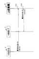
- FIG. 1is a diagram showing a configuration of a mobile communication system configured with HNB / HNB-GW / CN.
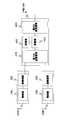
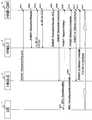
- FIG.It is a block diagram which shows the internal structure of HNB and a high-order apparatus in the mobile communication system of the 1st Embodiment of this invention. It is a sequence diagram explaining operation
- the overall configuration of the mobile communication system itselfis the same as that shown in FIG. (First embodiment)
- This embodimentis characterized by HNB-S2 and HNB-T3, and a higher-level device (hereinafter referred to as higher-level device 9) that is either the HNB-GW4 or the CN node 5.
- the HNB-S2's RFCI informationis notified from the HNB-S2 to the HNB-T3 via the host device 9.
- the HNB-S2 of the present embodimentincludes a control unit 21A that includes the RFCI information of the HNB-S2 in the first message, a transmission / reception unit 22A that transmits the first message to the higher-level device 9, Have
- the higher-level device 9 of the present embodimentincludes a transmission / reception unit 91A that receives the first message from the HNB-S2, and a control unit 92A that includes the RFCI information included in the first message in the second message. Then, the transmitting / receiving unit 91A transmits the second message to the HNB-T3.
- the HNB-T3 of the present embodimentinitializes the RFCI information of the HNB-T3 and the transmission / reception unit 31A that receives the second message from the higher-level device 9, and sets (re-set) the RFCI information included in the second message. And a control unit 32A for setting).
- step S101the HNB-S2 transmits a first message including the HCI-S2 RFCI information to the host device 9.
- step S102the host device 9 transmits the second message including the RFCI information included in the first message received from the HNB-S2 to the HNB-T3.
- the HNB-T3can take over the RFCI information from the HNB-S2 via the host device 9, intra-HNB-GW relocation occurs between the HNB-S2 and the HNB-T3. In some cases, there is an effect that a voice call can be performed while maintaining a transcoder-free operation (TrFO).
- the present embodimentis an example in which the host device 9 is HNB-GW 4 and the first embodiment is more specific.
- the HNB-S2's RFCI informationis notified from the HNB-S2 to the HNB-T3 via the HNB-GW4 by a RANAP message.
- the HNB-GW 4 of the present embodimentincludes an HNB transmission / reception unit 41B, a RANAP function unit 42B, a CN transmission / reception unit 43B, an Iu-UP frame control unit 44B, and an Iu-UP frame transfer unit. 45B and an RFCI holding unit 46B.
- the HNB transceiver 41Bconstitutes the transceiver 91A in FIG. 2, and the other functional blocks constitute the controller 92A in FIG.
- the HNB-S2 of the present embodimentincludes an anti-HNB-GW transmission / reception unit 21B, a RANAP function unit 22B, an Iu-UP frame control unit 23B, and an Iu-UP frame transfer unit 24B.
- the HNB-GW transmission / reception unit 21Bconstitutes the transmission / reception unit 22A of FIG. 2
- the other functional blocksconstitute the control unit 21A of FIG.
- the HNB-T3 of the present embodimentincludes a pair-to-HNB-GW transmission / reception unit 31B, a RANAP function unit 32B, an Iu-UP frame control unit 33B, and an Iu-UP frame transfer unit 34B.
- the HNB-GW transmission / reception unit 31Bconstitutes the transmission / reception unit 31A in FIG. 2
- the other functional blocksconstitute the control unit 32A in FIG.
- the HNB transceiver 41Bhas an interface for connecting to the HNB-S2 and HNB-T3, and transmits / receives audio data to / from the HNB-S2 and HNB-T3.
- the RANAP function units 22B, 32B, and 42Brealize a RANAP (Radio Access Network Application Part) protocol function defined by 3GPP TS 25.413 (Non-patent Document 3).
- the RANAP function units 22B, 32B, and 42Bhave a function of generating a RANAP message and a function of terminating the RANAP message.
- the CN transmission / reception unit 43 ⁇ / b> Bhas an interface for connection with the CN node 5, and transmits / receives voice data between the CN nodes 5.
- the Iu-UP frame control units 23B, 33B, and 44Brealize the Iu-UP protocol function defined in 3GPP TS25.415 (Non-Patent Document 2).
- the Iu-UP frame control units 23B, 33B, and 44Bhave a function of generating an Iu-UP Initialization message (hereinafter abbreviated as an Iu-UP Init message) and a function of terminating the Iu-UP Init message.
- the Iu-UP frame control unit 44Bhas a function of notifying the RFCI holding unit 46B of the RFCI information included in the Iu-UP Init message and the RFCI holding unit when the Iu-UP Initialization restarts. And a function of requesting comparison of RFCI information to 46B.
- the Iu-UP frame transfer units 24B, 34B, and 45Brealize the Iu-UP protocol function defined in 3GPP TS25.415 (Non-patent Document 2).
- the Iu-UP frame transfer units 24B, 34B, and 45Bhave a function of transferring Iu-UP frame data.
- the RFCI holding unit 46Bhas a function of holding the RFCI information notified from the Iu-UP frame control unit 44B, a function of notifying the comparison result based on the comparison request of the RFCI information from the Iu-UP frame control unit 44B, Have
- the HNB-GW transmission / reception units 21B and 31Bhave an interface for connecting to the HNB-GW 4, and transmit / receive audio data to / from the HNB-GW 4.
- a RAB parameter related to a radio access bearer (RAB) between a UE and a CNis set as a RANAP between the CN and the RNC (HNB-GW). It is stipulated to notify by message.
- the RAB parametersare QoS (Quality of Service) parameters (data transmission rate, block size, error rate, etc.) corresponding to the type of service.
- the RAB parameteris closely related to the RFCI information exchanged by the Iu-UP Initialization message, and only the RFCI information is changed by restarting the Iu-UP Initialization without changing the RAB parameter (RAB Modification). If this happens, there is a risk of inconsistencies in the state.
- 3GPP TS25.415(Non-Patent Document 2) specifies that Iu-UP Initialization from the same SRNS should not be restarted except for RAB Modification to prevent such procedures from occurring. (First provision).
- the mobile communication system configured by the existing Node-B / RNC / CNhas a function of taking over the RFCI information by the Iu-UP Initialization message
- the mobile communication system configured by the HNB / HNB-GW / CNWhen applied, in FIG. 1, Iu-UP Initialization is activated for CN 6 from each of HNB-S2 and HNB-T3. However, in this case, as seen from CN6, the same SRNS (HNB-GW4) restarts Iu-UP Initialization, which violates the first rule.
- Second regulationThe problem of the first regulation can be solved by terminating the Iu-UP Initialization message with the HNB-GW (that is, not terminating with the CN).
- Non-Patent Document 4if the Iu-UP message is terminated by the HNB-GW, there is a concern about the increase in signal processing and complexity of the HNB-GW. It is specified that the protocol message is not terminated by the HNB-GW (second specification). Therefore, when the Iu-UP Initialization message is terminated at the HNB-GW, the second rule is violated.
- the transcoder-free operation(TrFO) is maintained when intra-HNB-GW relocation occurs between HNB-S2 and HNB-T3 without changing the first and second rules. It is possible to make a voice call as it is.
- step S201the HNB-S2 starts a relocation procedure by transmitting a RANAP: Relocation Required message requesting the movement of the UE1 from the HNB-S2 to the HNB-GW4.
- the RFCI information of the Iu-UP Init messageis added to the 9.1.9 RANAP: Relocation Required message of 3GPP TS25.413 (Non-patent Document 3).
- FIG. 6shows a RANAP: Relocation Required message changed according to the present embodiment.
- FIG. 6shows only the changed part.
- the RFCI value “RFCI”“RFCI”
- the data size of each subflow “Length”are included. of Subflow "is added as RFCI information.
- the HNB-GW 4terminates the RANAP: Relocation Required message at the RANAP function unit 42B, and acquires the RFCI information.
- step S202the HNB-GW 4 sends a RANAP: Relocation Request message requesting the movement of the UE 1 to the HNB-T3 to the HNB-T3, thereby requesting the HNB-T3 to secure the resource.
- the RANAP function unit 42Bacquires the RFCI information and includes the RFCI information in the RANAP: Relocation Request message.
- FIG. 7shows a RANAP: Relocation Request message changed according to the present embodiment.
- FIG. 7shows only the changed part.
- RFCIthat is an RFCI value
- RCFI Subflowthat is the number of subflows constituting the data frame indicated by the RFCI value.
- And“ Length of Subflow ”which is the data size for each subflow, are added as RFCI information.
- the HNB-T3terminates the RANAP: Relocation Request message at the RANAP function unit 32B. If the RFCI information is included in the RANAP: Relocation Request message, the HNB-T3 initializes the RFCI information of the HNB-T3 and resets the RFCI information included in the RANAP: Relocation Request message.
- the HNB-T3subsequently receives uplink voice data from the UE1 and downlink voice data from the CN6, the structure of the data frame of the voice data is determined based on the RFCI value added to the voice data. In addition, the rate can be recognized correctly.
- FIG. 8shows an image of the Iu-UP Protocol state transition diagram changed according to the present embodiment. 8 shows a RANAP: Relocation Request message including RFCI information (in FIG. 8, Intra-HNB-GW Relocation-Req) is received, and the “Support Mode Data Transfer Ready” state is directly changed from the “NULL” state to the “Support Mode Data Transfer Ready” state. It means to make a transition.
- the HNB-T3receives a RANAP: Relocation Request message without executing the Iu-UP Initialization procedure
- the state of the Iu-UP frame transfer unit 33Bis changed from the “NULL” state using this as a trigger. , Transition to the “Support Mode Data Transfer Ready” state, and the Iu-UP frame data can be transferred.
- the signal name for transition from the “NULL” state to the “Support Mode Data Transfer Ready” stateis Intra-HNB-GW Relocation-Req, but the signal name is not limited to this.
- the HNB-T3After execution of step S202, the HNB-T3 responds to the RANAP: Relocation Request message by transmitting a RANAP: Relocation Request ACK message to the HNB-GW 4 in step S203.
- step S204the HNB-GW 4 sends a Relocation command message to the HNB-S2, thereby instructing the start of Relocation.
- step S205the HNB-S2 sends a RRC: Reconfiguration message to the UE 1 to instruct reconfiguration of the radio channel.
- step S206the HNB-T3 detects UE1 by synchronization with the wireless Layer1, and notifies the UE1 that it has detected by transmitting a Relocation Detect message to the HNB-GW4.
- step S207UE1 notifies RNB: Reconfiguration Complete message to HNB-T3 that radio resource allocation has been completed.
- step S208the HNB-T3 sends a RANAP: Relocation Complete message to the HNB-GW 4 to notify that the relocation has been completed.
- step S209the HNB-GW 4 sends a RANAP: Iu Release Command message to the HNB-S2, thereby requesting the release of the HNB-S2 resource.
- step S210the HNB-S2 sends a RANAP: Iu Release Complete message to the HNB-GW 4 to notify that the HNB-S2 resources have been released.
- step S211UE1 transmits / receives voice data (user data) to / from HNB-GW4 via HNB-T3.
- the HNB-S2notifies the HNB-S2 of the RFCI information of the HNB-S2 by the RANAP: Relocation Required message
- the HNB-GW4transmits the RFCI information of the HNB-S2 to the RANAP: Since the notification is sent to the HNB-T3 by the Relocation Request message, the HNB-T3 can take over the RFCI information from the HNB-S2 without executing the Iu-UP Initialization procedure.
- the HNB-T3transitions to a state in which the voice data can be transferred triggered by the reception of the RANAP: Relocation Request message from the HNB-GW4, the voice data can be transferred without executing the Iu-UP Initialization procedure. It becomes possible to transmit.
- the HNB-T3can take over the RFCI information from the HNB-S2 and transmit the voice data without executing the Iu-UP Initialization procedure. Therefore, the intra-connection between the HNB-S2 and the HNB-T3 is possible. Even when HNB-GW relocation occurs, a voice call can be performed while maintaining the transcoder-free operation (TrFO).
- 3GPP TS 25.467stipulates that the RANAP message is terminated at the HNB and HNB-GW. Therefore, there is an advantage that it is not necessary to newly support a protocol when adding a function related to the present embodiment to the RANAP message.
- Second MeritCurrently, 3GPP is examining the Intra HNB-GW Relocation procedure, but it is common to use a RANAP message for the signal of this procedure.
- the present embodimentis an example in which the host device 9 is HNB-GW 4 and the first embodiment is more specific.
- the HNB-S2's RFCI informationis notified from the HNB-S2 to the HNB-T3 via the HNB-GW4 by means of a Direct Transfer message of RANAP User Adaptation (hereinafter abbreviated as RUA).
- RUADirect Transfer message of RANAP User Adaptation
- RUAis defined in 3GPP TS 25.468 (Non-Patent Document 5). Further, the RUA Direct Transfer message is a message used for transferring the RANAP message.
- the HNB-GW 4 of this embodimentdiffers from the HNB-GW 4 of the second embodiment shown in FIG. 4 in that an RUA function unit 47B is added.
- the RUA function unit 47Bis one of the components constituting the control unit 92A of FIG.
- the HNB-S2 of the present embodimentis different from the HNB-S2 of the second embodiment shown in FIG. 4 in that an RUA function unit 25B is added.
- the RUA function unit 25Bis one of the components constituting the control unit 21A of FIG.
- the HNB-T3 of the present embodimentis different from the HNB-T3 of the second embodiment shown in FIG. 4 in that an RUA function unit 35B is added.
- the RUA function unit 35Bis one of the components constituting the control unit 32A of FIG.
- the RUA function units 25B, 35B, and 47Brealize the RUA protocol function defined in 3GPP TS 25.468 (Non-Patent Document 5).
- the RUA function units 25B, 35B, and 47Bhave a function of generating a RUA message and a function of terminating the RUA message.
- step S301the HNB-S2 starts a relocation procedure by transmitting a RANAP: Relocation Required message requesting the movement of the UE1 from the HNB-S2 to the HNB-GW4.
- FIG. 11shows the RUA Direct Transfer message changed according to the present embodiment. Note that FIG. 11 shows only the changed part.
- RFCIthat is an RFCI value
- RCFI Subflowthat is the number of subflows constituting the data frame indicated by the RFCI value
- Length ofthat is the data size of each subflow. Subflow "is added as RFCI information.
- the HNB-GW 4terminates the RANAP: Relocation Required message in the RANAP function unit 42B, and terminates the RUA Direct Transfer message in the RUA function unit 47B, and acquires the RFCI information.
- step S302the HNB-GW 4 requests the HNB-T3 to secure the resource by transmitting to the HNB-T3 a RANAP: Relocation Request message that requests the UE 1 to move to the HNB-T3.
- an RUA Direct Transfer message for transferring the RANAP: Relocation Request messageis also transmitted.
- the RUA function unit 47Bacquires the RFCI information and includes the RFCI information in the RUA Direct Transfer message.
- the RUA Direct Transfer message at this timeis the same as that shown in FIG.
- the HNB-T3terminates the RANAP: Relocation Request message in the RANAP function unit 32B and terminates the RUA Direct Transfer message in the RUA function unit 35B. If RFCI information is included in the RUA Direct Transfer message, the HNB-T3 initializes the RFCI information of the HNB-T3 and resets it to the RFCI information included in the RUA Direct Transfer message.
- the HNB-T3subsequently receives uplink voice data from the UE1 and downlink voice data from the CN6, the structure of the data frame of the voice data is determined based on the RFCI value added to the voice data. In addition, the rate can be recognized correctly.
- the HNB-T3triggers the reception of the RUA Direct Transfer message to change the state of the Iu-UP frame transfer unit 33B from the “NULL” state to the “Support Mode”. Transition to the “Data Transfer Ready” state, and the Iu-UP frame data can be transferred.
- the subsequent steps S303 to S311are the same as the steps S203 to S211 in FIG.
- the HNB-S2notifies the HNB-S2 of the RFCI information of the HNB-S2 by the RUA Direct Transfer message, and the HNB-GW4 transmits the RFCI information of the HNB-S2 to the RUA Direct Transfer. Since the message is notified to the HNB-T3, the HNB-T3 can take over the RFCI information from the HNB-S2 without executing the Iu-UP Initialization procedure.
- HNB-T3transmits voice data without executing the Iu-UP Initialization procedure because it transitions to a state in which voice data can be transferred triggered by reception of the RUA Direct Transfer message from HNB-GW4. It becomes possible to do.
- the HNB-T3can take over the RFCI information from the HNB-S2 and transmit the voice data without executing the Iu-UP Initialization procedure. Therefore, the intra-connection between the HNB-S2 and the HNB-T3 is possible. Even when HNB-GW relocation occurs, a voice call can be performed while maintaining the transcoder-free operation (TrFO).
- the present embodimentis an example in which the host device 9 is HNB-GW 4 and the first embodiment is more specific.
- the HNB-S2's RFCI informationis notified from the HNB-S2 to the HNB-T3 via the HNB-GW4 using a Relocation message of Home Node B Application Part (hereinafter abbreviated as HNBAP).
- HNBAPHome Node B Application Part
- HNBAPis defined in 3GPP TS 25.469 (Non-Patent Document 6).
- the HNBAP Relocation messageis not defined in 3GPP, and is well known as one of the proposals in the Intra HNB-GW relocation procedure currently being studied, and is not directly related to the present invention.
- the HNB-GW 4 of this embodimentis different from the HNB-GW 4 of the second embodiment shown in FIG. 4 in that an HNBAP function unit 48B is added.
- the HNBAP function unit 48Bis one of the components constituting the control unit 92A in FIG.
- the HNB-S2 of this embodimentis different from the HNB-S2 of the second embodiment shown in FIG. 4 in that an HNBAP function unit 26B is added.
- the HNBAP function unit 26Bis one of the components constituting the control unit 21A in FIG.
- the HNB-T3 of this embodimentis different from the HNB-T3 of the second embodiment shown in FIG. 4 in that an HNBAP function unit 36B is added.
- the HNBAP function unit 36Bis one of the components constituting the control unit 32A in FIG.
- the HNBAP function units 26B, 36B, and 48Brealize the HNBAP protocol function defined in 3GPP TS 25.469 (Non-Patent Document 6).
- the HNBAP function units 26B, 36B, and 48Bhave a function of generating an HNBAP message and a function of terminating the HNBAP message.
- step S401the HNB-S2 starts a relocation procedure by transmitting an HNBAP: Relocation Required message requesting the movement of the UE1 from the HNB-S2 to the HNB-GW4.
- the RFCI information of the Iu-UP Init messageis added to the HNBAP: Relocation Required message.
- RFCI informationcan be added to HNBAP: Relocation Required at this time, for example, as in FIG.
- the HNB-GW 4terminates the HNBAP: Relocation Required message at the HNBAP function unit 48B, and acquires the RFCI information.
- step S402the HNB-GW 4 requests the HNB-T3 to secure resources by transmitting an HNBAP: Relocation Request message requesting the movement of the UE 1 to the HNB-T3 to the HNB-T3.
- the HNBAP function unit 48Bacquires the RFCI information and includes the RFCI information in the HNBAP: Relocation Request message. At this time, RFCI information can be added to the HNBAP: Relocation Request message, for example, as in FIG.
- the HNB-T3terminates the HNBAP: Relocation Request message at the HNBAP function unit 36B. If RFCI information is included in the HNBAP: Relocation Request message, the HNB-T3 initializes the RFCI information of the HNB-T3, and resets the RFCI information included in the HNBAP: Relocation Request message.
- the HNB-T3subsequently receives uplink voice data from the UE1 and downlink voice data from the CN6, the structure of the data frame of the voice data is determined based on the RFCI value added to the voice data. In addition, the rate can be recognized correctly.
- Non-patent Document 2the state transition diagram of the Iu-UP Protocol of 3GPP TS25.415 (Non-patent Document 2) regarding the state transition of HNB-T3 (see FIG. 8), the “Support Mode directly from the“ NULL ”state.
- a condition for transitioning to the “Data Transfer Ready” statea condition for receiving an HNBAP: Relocation Request message including RFCI information (in FIG. 8, Intra-HNB-GW Relocation-Req) is added.
- the HNB-T3changes the state of the Iu-UP frame transfer unit 33B from the “NULL” state to the “Support” using the reception of the HNBAP: Relocation Request message as a trigger.
- the modeis changed to “Mode Data Transfer Ready” state, and the Iu-UP frame data can be transferred.
- the subsequent steps S403 to S411are the same as the steps S203 to S211 in FIG.
- the HNB-S2notifies the HNB-S2 of the RFCI information of the HNB-S2 to the HNB-GW4 using the HNBAP: Relocation Required message, and the HNB-GW4 transmits the RFCI information of the HNB-S2 to the HNBAP: Since the notification is sent to the HNB-T3 by the Relocation Request message, the HNB-T3 can take over the RFCI information from the HNB-S2 without executing the Iu-UP Initialization procedure.
- the HNB-T3transitions to a state in which the voice data can be transferred triggered by the reception of the HNBAP: Relocation Request message from the HNB-GW4, the voice data can be transferred without executing the Iu-UP Initialization procedure. It becomes possible to transmit.
- the HNB-T3can take over the RFCI information from the HNB-S2 and transmit the voice data without executing the Iu-UP Initialization procedure. Therefore, the intra-connection between the HNB-S2 and the HNB-T3 is possible. Even when HNB-GW relocation occurs, a voice call can be performed while maintaining the transcoder-free operation (TrFO).
- the present embodimentis an example in which the host device 9 is HNB-GW 4 and the first embodiment is more specific.
- the configuration of this embodimentis the same as that of the second embodiment shown in FIG.
- the HNB-GW 4notifies the HNB-T 3 of the RFCI information of the HNB-S 2 by the Iu-UP Init message during the relocation processing from the HNB-S 2 to the HNB-T 3 of the UE 1.
- the Iu-UP Init messageis transmitted and received between the HNB and the HNB-GW when the HNB tries to establish communication with the HNB under the control of the UE's communication partner, such as when a relocation occurs. Message.
- Non-Patent Document 2In Iu-UP Ver2 of 3GPP TS25.415 (Non-Patent Document 2), it is defined that an Iu-UP Init message is transmitted from the CN to the RNC. However, this rule presupposes a mobile communication system composed of existing Node-B / RNC / CN of 3GPP.
- Non-Patent Document 4Stipulates that messages of the Iu-UP protocol are not terminated by the HNB-GW.
- the specification of 3GPPis changed to allow the Iu-UP message to be terminated by the HNB-GW.
- HNB-GW 4has previously acquired the RFC information of the HNB-S2. That is, when establishing communication between HNB-S2 and HNB-X8, HNB-S2 sends an Iu-UP Init message including the RFCI information of HNB-S2 to HNB-GW4. , HNB-GW4 acquires the RFCI information of HNB-S2. This procedure is performed before step S501 in FIG. 14 and is not described in FIG.
- the HNB-T3transmits an Iu-UP Init message including the RFCI information of the HNB-T3 to the HNB-GW4.
- the HNB-GW 4terminates the Iu-UP Init message in the Iu-UP frame control unit 44B, and the HNB-T3 RFCI information included in the Iu-UP Init message and the HNB-S2 previously obtained RFCI information. Compare with.
- the HNB-GW 4responds to the Iu-UP Init message by transmitting an Iu-UP Init ACK message to the HNB-T 3 in step S504.
- step S503if the HCI-S2 and HNB-T3 RFCI information does not match, the HNB-GW4 matches the HNB-T3 RFCI information with the HNB-S2 RFCI information.
- step S505the HNB-S2 The Iu-UP Init message including the RFCI information is transmitted to the HNB-T3.
- the HNB-T3responds to the Iu-UP Init message by sending an Iu-UP Init ACK message to the HNB-GW 4 in step S506. Also, the HNB-T3 initializes the RFCI information of the HNB-T3 and resets it to the RFCI information of the HNB-S2 included in the Iu-UP Init message.
- steps S507 to S515is the same as the processing in steps S203 to S211 in FIG.
- the HNB-GW 4notifies the HNB-S2 of the RFCI information to the HNB-T3 by an Iu-UP Init message, so that the HNB-T3 takes over the RFCI information from the HNB-S2. Is possible.
- Non-Patent Document 4the description in 7.2 of 3GPP TS25.467 (Non-Patent Document 4), which is changed by this embodiment, is as follows.
- Iu-UPterminates only at CN, HNB, and HNB-GW.
- Non-Patent Document 2the description of Iu-UP Ver2 in 6.5.2 of 3GPP TS25.415 (Non-Patent Document 2), which is changed by this embodiment, is as follows.
- the initialization procedurecan be controlled by two Iu access points, that is, both CN and UTRAN.
- the initialization procedureis used to detect the mismatch of RFCI when indicated by the control function of the Iu-UP procedure, that is, when SRNS relocation or RAB establishment is performed on Iu, or when CN or HNB-GW is performing TrFO. Invoked when trying to resolve.
- the Initialization procedurecannot be restarted by SRNC for RAB without requesting RAB Modification by RANAP.
- Iu-UP Ver1 of 3GPP TS25.415(Non-Patent Document 2), it is specified that an Iu-UP Init message is transmitted from the RNC to the CN, but the Iu-UP Init message is transmitted from the CN to the RNC. Sending is not stipulated. Therefore, the rules for Iu-UP Ver1 may be revised in the same manner as Iu-UP Ver2.
- Non-Patent Document 2the description of Iu-UP Ver1 in 6.5.2 of 3GPP TS25.415 (Non-Patent Document 2), which is changed according to the present embodiment, is as follows.
- the initialization procedurecan be controlled by two Iu access points, that is, both CN and UTRAN.
- the initialization procedureis used to detect the mismatch of RFCI when indicated by the control function of the Iu-UP procedure, that is, when SRNS relocation or RAB establishment is performed on Iu, or when CN or HNB-GW is performing TrFO. Invoked when trying to resolve.
- the Initialization procedurecannot be restarted by SRNC for RAB without requesting RAB Modification by RANAP.
- the present embodimentis an example in which the host device 9 is the CN node 5 and the first embodiment is more specific.
- the CN node 5notifies the HNB-T3 of the RFCI information of the HNB-S2 by the Iu-UP Init message at the time of the relocation process from the HNB-S2 to the HNB-T3 of the UE1.
- the CN node 5performs the operation performed by the HNB-GW 4 in the third embodiment, and the HNB-GW 4 exchanges between the HNB-S2 / HNB-T3 and the CN node 5. Only the transfer is performed without terminating the RANAP message and the Iu-UP Init message.
- Non-Patent Document 2stipulates that restart of Iu-UP Initialization when Intra HNB-GW relocation occurs is not allowed.
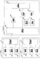
- the CN node 5includes an HNB-GW transmission / reception unit 51C for HNB-GW4, a RANAP function unit 52C, an HNB-GW transmission / reception unit 53C for HNB-GW7, an Iu -An UP frame control unit 54C, an Iu-UP frame transfer unit 55C, and an RFCI holding unit 56C.
- the HNB-GW transmission / reception unit 51Cconstitutes the transmission / reception unit 91A in FIG. 2, and the other functional blocks constitute the control unit 92A in FIG.
- HNB-S2 and HNB-T3 in the present embodimentare the same as the configurations of HNB-S2 and HNB-T3 in the second embodiment shown in FIG.
- the HNB-GW transmission / reception unit 51Chas an interface for connecting to the HNB-GW 4 and transmits / receives audio data to / from the HNB-GW 4.
- the HNB-GW transmission / reception unit 53Chas an interface for connecting to the HNB-GW 7, and transmits / receives audio data to / from the HNB-GW 7.
- the other RANAP function unit 52C, Iu-UP frame control unit 54C, Iu-UP frame transfer unit 55C, and RFCI holding unit 56Care respectively the RANAP function unit 42B and the Iu-UP frame control unit shown in FIG. The same operation as 44B, Iu-UP frame transfer unit 45B, and RFCI holding unit 46B is performed.
- the CN node 5has acquired the RFCI information of HNB-S2 in advance. That is, when establishing communication between HNB-S2 and HNB-X8, HNB-S2 sends an Iu-UP Init message including the RFCI information of HNB-S2 to CN node 5 via HNB-GW4. As a result, the CN node 5 acquires the RFCI information of the HNB-S2. This procedure is performed before step S601 in FIG. 16, and is not described in FIG.
- processing similar to that performed by HNB-S2, HNB-T3, and HNB-GW4 in steps S201 and S202 of FIG. 5is performed in steps S601 and S602, and HNB-S2, HNB-T3, and Performed by the CN node 5.
- step S603the HNB-T3 transmits an Iu-UP Init message including the RFCI information of the HNB-T3 to the CN node 5 via the HNB-GW4.
- the CN node 5terminates the Iu-UP Init message in the Iu-UP frame control unit 54C, and the HNB-T3 RFCI information included in the Iu-UP Init message and the previously acquired HNB-S2 RFCI information. Compare with.
- step S604the CN node 5 sends a response to the Iu-UP Init message by transmitting an Iu-UP Init ACK message to the HNB-T3 via the HNB-GW4.
- step S603if the RFCI information of HNB-S2 and HNB-T3 do not match, CN node 5 matches the RFCI information of HNB-T3 with the RFCI information of HNB-S2, so in step S605, HNB-S2 The Iu-UP Init message including the RFCI information is transmitted to the HNB-T3 via the HNB-GW4.
- step S606the HNB-T3 sends a response to the Iu-UP Init message by transmitting an Iu-UP Init ACK message to the CN node 5 via the HNB-GW4. Also, the HNB-T3 initializes the RFCI information of the HNB-T3 and resets it to the RFCI information of the HNB-S2 included in the Iu-UP Init message.
- processing performed by UE1, HNB-S2, HNB-T3, and CN node 5is performed in steps S203 to S211 of FIG. 5, UE1, HNB-S2, HNB-T3, and HNB- This is the same as the processing performed by GW4.
- the CN node 5notifies the HNB-S2 of the RFCI information of the HNB-S2 to the HNB-T3 by an Iu-UP Init message, so that the HNB-T3 takes over the RFCI information from the HNB-S2. Is possible.
- Non-Patent Document 2the description of Iu-UP Ver1 in 6.5.2 of 3GPP TS25.415 (Non-Patent Document 2), which is changed by this embodiment, is as follows.
- the Initialization procedurecannot be restarted for RAB without requesting RAB Modification by RANAP or without Intra HNB-GW relocation.
- Non-Patent Document 2the description of Iu-UP Ver2 in 6.5.2 of 3GPP TS25.415 (Non-Patent Document 2), which is changed by this embodiment, is as follows.
- the initialization procedurecannot be restarted for RAB without requesting RAB Modification by RANAP or without Intra HNB-GW relocation.
- the mobile communication system of this embodimentis characterized by HNB-S2 and HNB-T3, and HNB-GW4.
- each of the HNB-S2 and the HNB-T3notifies the RFCI information to the HNB-GW4, and when the HNB-GW4 does not match the RFCI information of the HNB-S2 and the HNB-T3, the HNB-T3
- the RFCI value added to the received audio datais converted into an RFCI value indicating a data frame having the same structure in the RFCI information of the HNB-S2.
- the HNB-S2 of the present embodimentincludes a control unit 21D that includes the RFCI information of the HNB-S2 in the first message, a transmission / reception unit 22D that transmits the first message to the HNB-GW4, Have
- the HNB-T3 of the present embodimentincludes a control unit 31D that includes the RFCI information of the HNB-T3 in the second message, and a transmission / reception unit 32D that transmits the second message to the HNB-GW4.
- the HNB-GW 4 of the present embodimentreceives the first message from the HNB-S2 and receives the second message from the HNB-T3, and the HNB included in the first message.
- the storage unit 42D that stores the RFCI information of S2 and the RFCI information of HNB-T3 included in the second messagedoes not match the RFCI information of HNB-S2 and HNB-T3, then the voice from HNB-T3
- the control unit 43Dthat performs the RFCI conversion for converting the RFCI value added to the voice data into the RFCI value indicating the data frame having the same structure as the voice data in the RFCI information of the HNB-S2.
- step S701the HNB-S2 transmits a first message including the RFCI information of the HNB-S2 to the HNB-GW4.
- step S702the HNB-T3 transmits a second message including the HCI-T3 RFCI information to the HNB-GW4.
- the HNB-GW 4stores the HNB-S2 RFCI information included in the first message and the HNB-T3 RFCI information included in the second message in the storage unit 42D. Also, the RFCI information of HNB-S2 and HNB-T3 is compared.
- step S703UE1 transmits / receives voice data (user data) to / from HNB-GW4 via HNB-T3.
- the HCI-S2 and the HNB-T3do not match the RFCI information
- the HCI-S2adds the RFCI value added to the audio data.
- RFCI conversionis performed to convert the data frame into the RFCI value indicating the data frame having the same structure as the voice data.
- the HNB-GW 4transmits the voice data to which the RFCI converted RFCI value is added to the CN 6.
- the HNB-GW 4transmits the voice data received from the HNB-T3 and the RFCI value added to the voice data to the CN 6 as they are. To do.
- the HNB-GW 4when the HNB-S4 and the HNB-T3 do not match the RFCI information, the HNB-GW 4 subsequently converts the RFCI value added to the audio data received from the HNB-T3 to the HNB-T3. -Convert to an RFCI value indicating a data frame of the same structure in the RFCI information of S2.
- each of the HNB-S2 and the HNB-T3notifies the RFCI information to the HNB-GW4 by an Iu-UP Init message, and the HNB-GW4 matches the RFCI information of the HNB-S2 and the HNB-T3. If not, the RFCI value added to the audio data received from the HNB-T3 is converted into an RFCI value indicating a data frame having the same structure in the RFCI information of the HNB-S2.
- Non-patent Document 4stipulates that messages of the Iu-UP protocol are not terminated by the HNB-GW.
- the specification of 3GPPis changed to allow the Iu-UP message to be terminated by the HNB-GW.
- the HNB-GW 4 of the present embodimentincludes an HNB transceiver 41E, a RANAP function unit 42E, a CN transceiver 43E, an Iu-UP frame controller 44E, and an Iu-UP frame transfer unit. 45E, an RFCI holding unit 46E, and an RFCI conversion unit 47E.
- the HNB transceiver 41Econstitutes the first transceiver 41D of FIG. 17
- the CN transceiver 43Econstitutes the second transceiver 44D of FIG. 17
- the RFCI holding unit 46E 17 storage units 42D, and the other functional blocksform the control unit 43B of FIG.
- the HNB-S2 of the present embodimentincludes an anti-HNB-GW transmission / reception unit 21E, a RANAP function unit 22E, an Iu-UP frame control unit 23E, and an Iu-UP frame transfer unit 24E.
- the HNB-GW transmission / reception unit 21Econstitutes the transmission / reception unit 22D of FIG. 17, and the other functional blocks constitute the control unit 21D of FIG.
- the HNB-T3 of the present embodimentincludes an anti-HNB-GW transmission / reception unit 31E, a RANAP function unit 32E, an Iu-UP frame control unit 33E, and an Iu-UP frame transfer unit 34E.
- the HNB-GW transmission / reception unit 31Econstitutes the transmission / reception unit 32D of FIG. 17, and the other functional blocks constitute the control unit 31D of FIG.
- the RFCI conversion unit 47Eperforms an RFCI conversion for converting the RFCI value added to the audio data received from the HNB-T3 into an RFCI value indicating a data frame having the same structure in the RFCI information of the HNB-S2.
- the other HNB transceiver 41E, the RANAP function unit 42E, the CN transceiver 43E, the Iu-UP frame controller 44E, the Iu-UP frame transfer unit 45E, and the RFCI holding unit 46Eare respectively 4 performs the same operations as those for the HNB transmission / reception unit 41B, the RANAP function unit 42B, the CN transmission / reception unit 43B, the Iu-UP frame control unit 44B, the Iu-UP frame transfer unit 45B, and the RFCI holding unit 46B shown in FIG. .
- the HNB-GW transmission / reception unit 21E, the RANAP function unit 22E, the Iu-UP frame control unit 23E, and the Iu-UP frame transfer unit 24Eare respectively connected to the HNB-GW transmission / reception shown in FIG. Operations similar to those of the unit 21B, the RANAP function unit 22B, the Iu-UP frame control unit 23B, and the Iu-UP frame transfer unit 24B are performed.
- the HNB-GW transmission / reception unit 31E, the RANAP function unit 32E, the Iu-UP frame control unit 33E, and the Iu-UP frame transfer unit 34Eare respectively connected to the HNB-GW transmission / reception shown in FIG. Operations similar to those of the unit 31B, the RANAP function unit 32B, the Iu-UP frame control unit 33B, and the Iu-UP frame transfer unit 34B are performed.
- HNB-GW 4has previously acquired the RFC information of the HNB-S2. That is, when establishing communication between HNB-S2 and HNB-X8, HNB-S2 sends an Iu-UP Init message including the RFCI information of HNB-S2 to HNB-GW4. , HNB-GW4 acquires the RFCI information of HNB-S2. This procedure is performed before step S801 in FIG. 20, and is not described in FIG.
- steps S801 and S802similar to the processing in steps S201 and S202 in FIG. 5 is performed.
- step S803the HNB-T3 transmits an Iu-UP Init message including the RFCI information of the HNB-T3 to the HNB-GW4.
- the HNB-GW 4terminates the Iu-UP Init message at the Iu-UP frame control unit 44E, and the HNB-T3 RFCI information included in the Iu-UP Init message and the HNB-S2 previously obtained RFCI information. Compare with.
- step S804the HNB-GW 4 sends a response to the Iu-UP Init message by transmitting an Iu-UP Init ACK message to the HNB-T3.
- Steps S805 to S812Similar to the processing of Steps S203 to S211 of FIG. 5 is performed, and then UE1 transmits the HNB-GW4 and the voice data (user data) via HNB-T3 in Step S813. Send and receive.
- the RFCI information of HNB-S2 and HNB-T3does not match in step S803
- the RFCI information of HNB-T3 and HNB-X8also do not match.
- the two RFCI information of HNB-T3 and HNB-X8even if the RFCI value is the same, it may indicate a data frame with a different structure, so it is transmitted from UE1 via HNB-T3.
- the received voice dataneeds to be subjected to RFCI conversion.
- the HNB-GW 4transfers the audio data transmitted from the UE 1 via the HNB-T3 from the Iu-UP frame transfer unit 45E to the RFCI conversion unit 47E, and adds it to the audio data at the RFCI conversion unit 47E.
- the RFCI conversionis performed for converting the RFCI value thus converted into an RFCI value indicating a data frame having the same structure as the voice data in the RFCI information of the HNB-S2. Thereafter, the audio data to which the RFCI-converted RFCI value is added is transferred to the Iu-UP frame transfer unit 45E and transmitted to the CN 6 via the CN transmission / reception unit 43E.
- the HNB-GW 4when the HNB-S4 and the HNB-T3 do not match the RFCI information, the HNB-GW 4 subsequently converts the RFCI value added to the audio data received from the HNB-T3 to the HNB-T3. -Convert to an RFCI value indicating a data frame of the same structure in the RFCI information of S2.
- Non-Patent Document 4the description in 7.2 of 3GPP TS25.467 (Non-Patent Document 4), which is changed according to the present embodiment, is as follows.
- Iu-UPterminates only at CN, HNB, and HNB-GW.
- control information handed over from the HNB-S2 to the HNB-T3has been described as being only the RFCI information.
- the present inventionis not limited to this, and the IPTI (Inter PDU Transmission Interval) is used. ) Additional information may be taken over.
- the IPTI informationdefines the data transmission interval (cycle) of the subflow, and the IPTI information uniquely calculates the audio data based on the toll data size of the subflow and the AMR codec rate without taking over the audio data. can do.
- the present inventioncan be applied to intra-HNB-GW relocation between HNBs.
- the present inventionis based on inter-HNB-GW relocation (HNB-S2 and HNB-T3). May be applied to a relocation where the HNB-GW to which is connected is not the same.
- the HNB-T3transmits the HNB-T3 RFCI information included in the Iu-UP Init message, but at the time of attempting to transmit the Iu-UP Init message. If the HNB-S2 RFCI information is received, the transmission of the Iu-UP Init message by the HNB-T3 may be prohibited.
- the method performed in the HNB-S, HNB-T, HNB-GW, and CN node of the present inventionmay be applied to a program for causing a computer to execute.
- the programcan be stored in a storage medium and can be provided to the outside via a network.
Landscapes
- Engineering & Computer Science (AREA)
- Computer Networks & Wireless Communication (AREA)
- Signal Processing (AREA)
- Mobile Radio Communication Systems (AREA)
Abstract
Description
Translated fromJapanese本発明は、移動通信システム、基地局、上位装置、ゲートウェイ装置、通信方法、プログラムに関する。The present invention relates to a mobile communication system, a base station, a host device, a gateway device, a communication method, and a program.
3GPP(3rd Generation Partnership Project)の既存の移動通信システムとして、Node-B(基地局)と、RNC(Radio Network Controller)と、CN(Core Network:コアネットワーク)と、から構成される移動通信システムがある。As an existing mobile communication system of 3GPP (3rd Generation Partnership Project), there is a mobile communication system composed of Node-B (base station), RNC (Radio Network Controller), and CN (Core Network). is there.
このような構成の移動通信システムにおける音声データの符号化方式として、AMR(Adaptive Multi-Rate)が挙げられる。AMRは、回線状況等に応じて、動的に音声データのレートを変更する方式である。As an audio data encoding method in the mobile communication system having such a configuration, there is AMR (Adaptive Multi-Rate). AMR is a method for dynamically changing the rate of voice data in accordance with the line conditions and the like.
AMRを用いる移動通信システムでは、音声データの符号化と復号化のレートを同じにするために、CN内にトランスコーダを設置し、必要に応じて、トランスコーダにより再符号化(トランスコード)を行っている。In a mobile communication system using AMR, a transcoder is installed in the CN in order to make the voice data encoding and decoding rates the same, and recoding (transcoding) is performed by the transcoder as necessary. Is going.
AMRにより符号化された音声データのデータフレームは、データサイズが異なる複数のサブフローから構成される。これら複数のサブフレームの組み合わせは、音声データのレートに応じて異なり、その組み合わせごとにRFCI(RAB sub-Flow Combination Indicator)値が識別子として規定されている。すなわち、RFCI値は、音声データのレートごとに定義されることになる。A data frame of audio data encoded by AMR is composed of a plurality of subflows having different data sizes. The combination of the plurality of subframes varies depending on the audio data rate, and an RFCI (RAB sub-flow combination indicator) value is defined as an identifier for each combination. That is, the RFCI value is defined for each audio data rate.
また、AMRを用いる移動通信システムでは、各Node-Bに、音声符号化における制御情報として、RFCI情報が設定されている。RFCI情報は、RFCI値ごとに、そのRFCI値が示すデータフレームの構造を識別する情報、具体的には、そのデータフレームを構成するサブフロー数とサブフロー毎のデータサイズに関する情報を含んでいる。なお、RFCI情報は、AMR以外に、Wide-Band AMR(広帯域の音声コーデック)やCSストリーミングサービス(Faxやモデム通信)にも用いられる。Also, in a mobile communication system using AMR, RFCI information is set in each Node-B as control information in speech coding. The RFCI information includes information for identifying the structure of the data frame indicated by the RFCI value for each RFCI value, specifically, information on the number of subflows constituting the data frame and the data size for each subflow. In addition to AMR, the RFCI information is also used for Wide-Band AMR (broadband audio codec) and CS streaming service (Fax and modem communication).
Node-Bは、あるレートで符号化した音声データを送信する場合、そのレートに対応するRFCI値を付加した音声データを他のNode-Bに送信し、また、他のNode-Bから音声データを受信した場合、その音声データに付加されているRFCI値に対応するレートで、その音声データを復号化する。When transmitting audio data encoded at a certain rate, the Node-B transmits the audio data to which the RFCI value corresponding to the rate is added to the other Node-B, and the audio data from the other Node-B. , The audio data is decoded at a rate corresponding to the RFCI value added to the audio data.
ここで、UE(User Equipment:端末)が2つのNode-Bを介して音声通話を行う場合に、2つのNode-B間でRFCI情報が一致していれば、これら2つのRFCI情報において、各RFCI値は同じ構造のデータフレームを示していることになる。そのため、2つのNode-B間では、CN内のトランスコーダを経由しなくても、同じレートで音声データの符号化/復号化を行うことが可能となる。このようにトランスコーダを経由せずに音声通話を行う方式を、トランスコーダフリーオペレーション(TrFO:Transcoder Free Operation)という。この方式は、3GPP TS23.153(非特許文献1)で規定されている。Here, when a UE (User Equipment: terminal) performs a voice call through two Node-Bs, if the two pieces of RFCI information match between the two Node-Bs, The RFCI value indicates a data frame having the same structure. Therefore, audio data can be encoded / decoded between the two Node-Bs at the same rate without going through a transcoder in the CN. Such a method of performing a voice call without going through a transcoder is called a transcoder free operation (TrFO). This method is defined in 3GPP TS 23.153 (Non-Patent Document 1).
その一方、2つのNode-B間でRFCI情報が不一致であれば、これら2つのRFCI情報においては、RFCI値が同じであっても、異なる構造のデータフレームを示している場合がある。この場合、トランスコーダを経由しないと、2つのNode-B間で同じレートで音声データの符号化/復号化を行うことはできないことから、トランスコーダフリーオペレーション(TrFO)を維持したまま音声通話を行うことはできない。On the other hand, if the RFCI information does not match between the two Node-Bs, the two RFCI information may indicate data frames having different structures even if the RFCI values are the same. In this case, since voice data cannot be encoded / decoded at the same rate between the two Node-Bs without going through the transcoder, a voice call can be made while maintaining the transcoder-free operation (TrFO). Can't do it.
したがって、トランスコーダフリーオペレーション(TrFO)を維持したまま、音声通話を行うには、2つのNode-B間でRFCI情報を一致させることが望ましい。Therefore, in order to make a voice call while maintaining the transcoder-free operation (TrFO), it is desirable to match the RFCI information between the two Node-Bs.
しかし、移動通信システムでは、UEの移動が頻繁に発生するため、UEが移動前に接続する移動元Node-BとUEが移動後に接続する移動先Node-BとでRFCI情報が一致しない場合も多いと考えられる。However, in a mobile communication system, movement of the UE frequently occurs, and therefore, the RFCI information may not match between the source Node-B to which the UE connects before moving and the destination Node-B to which the UE connects after moving. It is thought that there are many.
そこで、3GPP TS25.415(非特許文献2)では、UEの移動元Node-Bが接続されるRNCと移動先Node-Bが接続されるRNCとが異なる、いわゆるSRNS(Serving Radio Network Subsystem)リロケーションの発生時に、RNC間で、CNを介して、Iu-UP(Iu interface user plane)プロトコルにて規定されるIu-UP Initializationメッセージにより、RFCI情報の引継ぎを行うことが規定されている。Therefore, in 3GPP TS25.415 (Non-Patent Document 2), so-called SRNS (Serving Radio Network Subsystem) relocation, in which the RNC to which the UE's source Node-B is connected and the RNC to which the destination Node-B is connected, is different. It is specified that, when an error occurs, RFCI information is taken over between RNCs via an Iu-UP Initialization message specified by the Iu-UP (Iu interface user plane) protocol via CN.
ところで、昨今、3GPPでは、HNB(Home Node-B:小型基地局)と呼ばれる、家庭および小規模オフィス向けの小型基地局と、HNB-GW(Home Node-Gateway)と、CNと、から構成される移動通信システムが検討されている。この移動通信システムの構成を、図1を用いて詳細に説明する。By the way, recently, 3GPP is composed of a small base station for homes and small offices called HNB (Home Node-B: small base station), an HNB-GW (Home Node-Gateway), and CN. Mobile communication systems are being studied. The configuration of this mobile communication system will be described in detail with reference to FIG.
図1を参照すると、この移動通信システムは、UE1と、HNB-S2と、HNB-T3と、HNB-GW4と、CNノード5を含むCN6と、HNB-GW7と、HNB-X8と、を有する。Referring to FIG. 1, this mobile communication system includes UE1, HNB-S2, HNB-T3, HNB-GW4, CN6 including
UE1は、第3世代移動携帯電話(端末)である。UE1 is a third generation mobile cellular phone (terminal).
HNB-S2、HNB-T3、およびHNB-X8は、家庭および小規模オフィス向けの小型基地局である。HNB-S2, HNB-T3, and HNB-X8 are small base stations for homes and small offices.
HNB-S2は、UE1が移動前に接続する移動元HNBである。HNB-S2 is a source HNB to which UE1 connects before moving.
HNB-T3は、UE1が移動後に接続する移動先HNBである。HNB-T3 is a destination HNB to which UE1 connects after moving.
HNB-X8は、UE1の通信相手のUE(不図示)を配下に持つHNBである。The HNB-X8 is an HNB having a UE (not shown) as a communication partner of the UE1 under its control.
HNB-GW4は、HNB-S2およびHNB-T3をCN6に接続するゲートウェイ装置であり、また、HNB-GW7は、HNB-X8をCN6に接続するゲートウェイ装置である。HNB-GW4 is a gateway device that connects HNB-S2 and HNB-T3 to CN6, and HNB-GW7 is a gateway device that connects HNB-X8 to CN6.
CN6は、第3世代移動交換網である。CN6 is a third generation mobile switching network.
CNノード5は、CN6内に設けられたHMS(Home NodeB Management System)やMSC(Mobile Switching Center)などのコアネットワーク装置である。
UE1は、同一のHNB-GW4配下のHNB-S2からHNB-T3へ移動する。このような移動を、intra-HNB-GWリロケーションと呼ぶ。UE1 moves from HNB-S2 under the same HNB-GW4 to HNB-T3. Such movement is called intra-HNB-GW relocation.
UE1は、移動前は、HNB-S2、HNB-GW4、CN6、HNB-GW7、およびHNB-X8を介して、HNB-X8配下のUEと音声通話を行う。Before moving, UE1 performs a voice call with a UE under HNB-X8 via HNB-S2, HNB-GW4, CN6, HNB-GW7, and HNB-X8.
また、UE1は、移動後は、HNB-T3、HNB-GW4、CN6、HNB-GW7、およびHNB-X8を介して、HNB-X8配下のUEと音声通話を行う。Also, after moving, UE1 performs a voice call with a UE under HNB-X8 via HNB-T3, HNB-GW4, CN6, HNB-GW7, and HNB-X8.
なお、図1において、UE1の通信相手の対向のシステムは、HNB-X8/HNB-GW7/CN6で構成される3GPP無線通信システムになっているが、既存のNode-B/RNC/CNで構成される3GPP無線通信システムであってもよい。In FIG. 1, the opposite system of the communication partner of UE1 is a 3GPP wireless communication system configured by HNB-X8 / HNB-GW7 / CN6, but is configured by an existing Node-B / RNC / CN. 3GPP wireless communication system may be used.
ここで、HNBは、携帯電話事業者ではなく、個人が設置することが想定される。そのため、HNB-S2およびHNB-T3は、同一のHNB-GW4の配下にあるものの、ベンダが異なることが想定される。Here, it is assumed that the HNB is installed by an individual, not a mobile phone operator. Therefore, it is assumed that HNB-S2 and HNB-T3 are under the same HNB-GW4 but have different vendors.
従って、UE1によるHNB-S2とHNB-T3間のintra-HNB-GWリロケーションの発生時に、HNB-S2とHNB-T3間でRFCI情報が一致しないことも十分に考えられる。Therefore, when the intra-HNB-GW relocation between the HNB-S2 and the HNB-T3 by the UE1 occurs, it is fully possible that the RFCI information does not match between the HNB-S2 and the HNB-T3.
もし、RFCI情報が一致しない場合、トランスコーダフリーオペレーション(TrFO)を維持したまま、音声通話を行うことができなくなるという課題が生じる。If the RFCI information does not match, there arises a problem that a voice call cannot be performed while maintaining the transcoder-free operation (TrFO).
そこで、3GPPでは、HNB/HNB-GW/CNで構成される移動通信システムにおいても、HNB間のintra-HNB-GWリロケーションの方法の標準化に向けた議論がなされているが、HNB間でRFCI情報が一致しない場合の解決方法は何ら提示されていない。Therefore, in 3GPP, even in a mobile communication system composed of HNB / HNB-GW / CN, there is a discussion for standardization of intra-HNB-GW relocation method between HNBs. There is no suggestion of how to solve the problem.
そこで、本発明の目的は、上述した課題を解決し、HNB間のintra-HNB-GWリロケーション発生時にも、トランスコーダフリーオペレーション(TrFO)を維持したまま、音声通話を行うことができる移動通信システム、基地局、上位装置、ゲートウェイ装置、通信方法、プログラムを提供することにある。SUMMARY OF THE INVENTION Accordingly, an object of the present invention is to solve the above-described problems and to perform a voice call while maintaining a transcoder-free operation (TrFO) even when intra-HNB-GW relocation occurs between HNBs. A base station, a host device, a gateway device, a communication method, and a program.
本発明の第1の移動通信システムは、
端末と、前記端末が移動前に接続する移動元基地局と、前記端末が移動後に接続する移動先基地局と、前記移動元基地局および前記移動先基地局を配下に持つ上位装置と、を有してなる移動通信システムであって、
前記移動元基地局および前記移動先基地局は、音声符号化における制御情報が予め設定されており、
前記移動元基地局は、自局の前記制御情報を第1のメッセージに含め、該第1のメッセージを前記上位装置に送信し、
前記上位装置は、前記移動元基地局の前記制御情報を第2のメッセージに含め、該第2のメッセージを前記移動先基地局に送信する。The first mobile communication system of the present invention is:
A terminal, a source base station to which the terminal connects before moving, a destination base station to which the terminal connects after moving, and a host device under the control of the source base station and the destination base station, A mobile communication system comprising:
The source base station and the destination base station are preset with control information in speech coding,
The source base station includes the control information of its own station in a first message, and transmits the first message to the host device.
The higher-level device includes the control information of the source base station in a second message and transmits the second message to the destination base station.
本発明の第2の移動通信システムは、
端末と、前記端末が移動前に接続する移動元基地局と、前記端末が移動後に接続する移動先基地局と、前記移動元基地局および前記移動先基地局をコアネットワークに接続するゲートウェイ装置と、を有してなる移動通信システムであって、
前記移動元基地局および前記移動先基地局は、音声符号化における制御情報として、識別子ごとに、該識別子が示す、音声符号化された音声データのデータフレームの構造を識別する制御情報が予め設定されており、
前記移動元基地局は、自局の前記制御情報を第1のメッセージに含め、該第1のメッセージを前記ゲートウェイ装置に送信し、
前記移動先基地局は、自局の前記制御情報を第2のメッセージに含め、該第2のメッセージを前記ゲートウェイ装置に送信し、
前記ゲートウェイ装置は、
前記第1のメッセージに含まれる、前記移動元基地局の前記制御情報と、前記第2のメッセージに含まれる、前記移動先基地局の前記制御情報と、を格納し、
前記移動元基地局および前記移動先基地局の前記制御情報が一致しない場合、以降に、前記移動先基地局から音声データを受信すると、該音声データに付加されている識別子を、前記移動元基地局の前記制御情報内で同じ構造のデータフレームを示している識別子に変換し、
前記変換された識別子が付加された音声データを前記コアネットワークに送信する。The second mobile communication system of the present invention is
A terminal, a source base station to which the terminal connects before moving, a destination base station to which the terminal connects after moving, and a gateway apparatus for connecting the source base station and the destination base station to a core network A mobile communication system comprising:
For each identifier, the source base station and the destination base station set in advance control information for identifying the structure of the data frame of the voice encoded voice data indicated by the identifier, as control information in voice encoding. Has been
The source base station includes the control information of its own station in a first message, and transmits the first message to the gateway device.
The destination base station includes the control information of its own station in a second message, and transmits the second message to the gateway device.
The gateway device is
Storing the control information of the source base station included in the first message and the control information of the destination base station included in the second message;
When the control information of the source base station and the destination base station do not match, when voice data is subsequently received from the destination base station, the identifier added to the voice data is changed to the source base station. Converted into an identifier indicating a data frame of the same structure in the control information of the station,
The voice data to which the converted identifier is added is transmitted to the core network.
本発明の第1の基地局は、
端末が移動前に接続する移動元の基地局であって、
音声符号化における制御情報が予め設定されており、自局の前記制御情報をメッセージに含める制御部と、
前記メッセージを上位装置に送信する送受信部と、を有する。The first base station of the present invention
The source base station to which the terminal connects before moving,
Control information in speech encoding is preset, a control unit that includes the control information of its own station in a message,
A transmission / reception unit that transmits the message to a higher-level device.
本発明の第2の基地局は、
端末が移動後に接続する移動先の基地局であって、
音声符号化における制御情報が予め設定されている制御部と、
上位装置から、前記端末が移動前に接続していた移動元の基地局の前記制御情報を含む第1のメッセージを受信する送受信部と、を有する。The second base station of the present invention
The base station to which the terminal connects after moving,
A control unit in which control information in speech encoding is preset;
And a transmission / reception unit that receives a first message including the control information of the source base station to which the terminal was connected before the movement from the host device.
本発明の上位装置は、
端末が移動前に接続する移動元基地局と、前記端末が移動後に接続する移動先基地局と、を配下に持つ上位装置であって、
前記移動元基地局および前記移動先基地局は、音声符号化における制御情報が予め設定されており、
前記移動元基地局から、前記移動元基地局の前記制御情報を含む第1のメッセージを受信する送受信部と、
前記移動元基地局の前記制御情報を第2のメッセージに含める制御部と、を有し、
前記送受信部は、前記第2のメッセージを前記移動先基地局に送信する。The host device of the present invention is
A host device under control of a source base station to which the terminal connects before moving and a destination base station to which the terminal connects after moving;
The source base station and the destination base station are preset with control information in speech coding,
A transmission / reception unit for receiving a first message including the control information of the source base station from the source base station;
A control unit including the control information of the source base station in a second message,
The transmission / reception unit transmits the second message to the destination base station.
本発明のゲートウェイ装置は、
端末が移動前に接続する移動元基地局と、前記端末が移動後に接続する移動先基地局と、をコアネットワークに接続するゲートウェイ装置であって、
前記移動元基地局および前記移動先基地局は、音声符号化における制御情報として、識別子ごとに、該識別子が示す、音声符号化された音声データのデータフレームの構造を識別する制御情報が予め設定されており、
前記移動元基地局から、前記移動元基地局の前記制御情報を含む第1のメッセージを受信するとともに、前記移動先基地局から、前記移動先基地局の前記制御情報を含む第2のメッセージを受信する送受信部と、
前記第1のメッセージに含まれる、前記移動元基地局の前記制御情報と、前記第2のメッセージに含まれる、前記移動先基地局の前記制御情報と、を格納する記憶部と、
前記移動元基地局および前記移動先基地局の前記制御情報が一致しない場合、以降に、前記移動先基地局から音声データを受信すると、該音声データに付加されている識別子を、前記移動元基地局の前記制御情報内で同じ構造のデータフレームを示している識別子に変換する制御部と、
前記変換された識別子が付加された音声データを前記コアネットワークに送信する第2の送受信部と、を有する。The gateway device of the present invention
A gateway device that connects a source base station to which a terminal is connected before moving and a destination base station to which the terminal is connected after moving to a core network,
For each identifier, the source base station and the destination base station set in advance control information for identifying the structure of the data frame of the voice encoded voice data indicated by the identifier, as control information in voice encoding. Has been
A first message including the control information of the source base station is received from the source base station, and a second message including the control information of the destination base station is received from the destination base station. A transmission / reception unit for receiving;
A storage unit for storing the control information of the source base station included in the first message and the control information of the destination base station included in the second message;
When the control information of the source base station and the destination base station do not match, when voice data is subsequently received from the destination base station, the identifier added to the voice data is changed to the source base station. A control unit for converting to an identifier indicating a data frame of the same structure in the control information of the station;
A second transmission / reception unit that transmits the audio data to which the converted identifier is added to the core network.
本発明の第1の通信方法は、
端末と、前記端末が移動前に接続する移動元基地局と、前記端末が移動後に接続する移動先基地局と、前記移動元基地局および前記移動先基地局を配下に持つ上位装置と、を有してなる移動通信システムによる通信方法であって、
前記移動元基地局が、自局の音声符号化における制御情報を第1のメッセージに含め、該第1のメッセージを前記上位装置に送信するステップと、
前記上位装置が、前記移動元基地局の前記制御情報を第2のメッセージに含め、該第2のメッセージを前記移動先基地局に送信するステップと、を有する。The first communication method of the present invention includes:
A terminal, a source base station to which the terminal connects before moving, a destination base station to which the terminal connects after moving, and a host device under the control of the source base station and the destination base station, A communication method using a mobile communication system comprising:
The source base station includes control information in its own speech coding in a first message, and transmits the first message to the host device;
The host device includes the control information of the source base station in a second message, and transmits the second message to the destination base station.
本発明の第2の通信方法は、
端末と、前記端末が移動前に接続する移動元基地局と、前記端末が移動後に接続する移動先基地局と、前記移動元基地局および前記移動先基地局をコアネットワークに接続するゲートウェイ装置と、を有してなる移動通信システムによる通信方法であって、
前記移動元基地局が、自局の音声符号化における制御情報として、識別子ごとに、該識別子が示す、音声符号化された音声データのデータフレームの構造を識別する制御情報を第1のメッセージに含め、該第1のメッセージを前記ゲートウェイ装置に送信するステップと、
前記移動先基地局が、自局の前記制御情報を第2のメッセージに含め、該第2のメッセージを前記ゲートウェイ装置に送信するステップと、
前記ゲートウェイ装置が、前記第1のメッセージに含まれる、前記移動元基地局の前記制御情報と、前記第2のメッセージに含まれる、前記移動先基地局の前記制御情報と、を格納するステップと、
前記ゲートウェイ装置が、前記移動元基地局および前記移動先基地局の前記制御情報が一致しない場合、以降に、前記移動先基地局から音声データを受信すると、該音声データに付加されている識別子を、前記移動元基地局の前記制御情報内で同じ構造のデータフレームを示している識別子に変換するステップと、
前記ゲートウェイ装置が、前記変換された識別子が付加された音声データを前記コアネットワークに送信するステップと、を有する。The second communication method of the present invention includes:
A terminal, a source base station to which the terminal connects before moving, a destination base station to which the terminal connects after moving, and a gateway apparatus for connecting the source base station and the destination base station to a core network A communication method by a mobile communication system comprising:
As the control information in the speech encoding of the local station, the source base station uses, for each identifier, control information for identifying the structure of the data frame of the speech encoded speech data indicated by the identifier in the first message. Including the step of transmitting the first message to the gateway device;
The destination base station includes the control information of its own station in a second message, and transmits the second message to the gateway device;
The gateway device storing the control information of the source base station included in the first message and the control information of the destination base station included in the second message; ,
When the gateway device receives the voice data from the destination base station after that when the control information of the source base station and the destination base station do not match, the identifier added to the voice data is changed to the identifier. Converting to an identifier indicating a data frame of the same structure in the control information of the source base station;
And the gateway device transmitting voice data to which the converted identifier is added to the core network.
本発明の第3の通信方法は、
端末が移動前に接続する移動元の基地局による通信方法であって、
自局の音声符号化における制御情報をメッセージに含めるステップと、
前記メッセージを上位装置に送信するステップと、を有する。The third communication method of the present invention is:
A communication method by a source base station to which a terminal connects before moving,
Including control information in the voice encoding of the local station in the message;
Transmitting the message to a higher-level device.
本発明の第4の通信方法は、
端末が移動後に接続する移動先の基地局による通信方法であって、
上位装置から、前記端末が移動前に接続していた移動元の基地局の音声符号化における制御情報を含む第1のメッセージを受信するステップと、を有する。The fourth communication method of the present invention is:
A communication method by a destination base station to which a terminal connects after moving,
Receiving from the host device a first message including control information in speech encoding of the source base station to which the terminal was connected before moving.
本発明の第5の通信方法は、
端末が移動前に接続する移動元基地局と、前記端末が移動後に接続する移動先基地局と、を配下に持つ上位装置による通信方法であって、
前記移動元基地局から、前記移動元基地局の音声符号化における制御情報を含む第1のメッセージを受信するステップと、
前記移動元基地局の前記制御情報を第2のメッセージに含めるステップと、
前記第2のメッセージを前記移動先基地局に送信するステップと、を有する。The fifth communication method of the present invention is:
A communication method by a host device under control of a source base station to which a terminal connects before moving and a destination base station to which the terminal connects after moving,
Receiving from the source base station a first message including control information in speech encoding of the source base station;
Including the control information of the source base station in a second message;
Transmitting the second message to the destination base station.
本発明の第6の通信方法は、
端末が移動前に接続する移動元基地局と、前記端末が移動後に接続する移動先基地局と、をコアネットワークに接続するゲートウェイ装置による通信方法であって、
前記移動元基地局から、前記移動元基地局の音声符号化における制御情報として、識別子ごとに、該識別子が示す、音声符号化された音声データのデータフレームの構造を識別する制御情報を含む第1のメッセージを受信するとともに、前記移動先基地局から、前記移動先基地局の前記制御情報を含む第2のメッセージを受信するステップと、
前記第1のメッセージに含まれる、前記移動元基地局の前記制御情報と、前記第2のメッセージに含まれる、前記移動先基地局の前記制御情報と、を格納するステップと、
前記移動元基地局および前記移動先基地局の前記制御情報が一致しない場合、以降に、前記移動先基地局から音声データを受信すると、該音声データに付加されている識別子を、前記移動元基地局の前記制御情報内で同じ構造のデータフレームを示している識別子に変換するステップと、
前記変換された識別子が付加された音声データを前記コアネットワークに送信するステップと、を有する。The sixth communication method of the present invention is:
A communication method by a gateway device that connects a source base station to which a terminal connects before moving and a destination base station to which the terminal connects after moving to a core network,
Control information for identifying the structure of a data frame of voice-coded voice data indicated by the identifier is provided for each identifier as control information in voice coding of the source base station from the source base station. Receiving a second message including the control information of the destination base station from the destination base station;
Storing the control information of the source base station included in the first message and the control information of the destination base station included in the second message;
When the control information of the source base station and the destination base station do not match, when voice data is subsequently received from the destination base station, the identifier added to the voice data is changed to the source base station. Converting to an identifier indicating a data frame of the same structure in the control information of a station;
Transmitting the voice data to which the converted identifier is added to the core network.
本発明の第1のプログラムは、
端末が移動前に接続する移動元の基地局に、
自局の音声符号化における制御情報をメッセージに含める手順と、
前記メッセージを上位装置に送信する手順と、を実行させる。The first program of the present invention is:
To the source base station that the terminal connects to before moving,
A procedure for including control information in the speech encoding of the own station in the message;
And a procedure for transmitting the message to a host device.
本発明の第2のプログラムは、
端末が移動後に接続する移動先の基地局に、
上位装置から、前記端末が移動前に接続していた移動元の基地局の音声符号化における制御情報を含む第1のメッセージを受信する手順を実行させる。The second program of the present invention is:
To the base station to which the terminal connects after moving,
A procedure for receiving a first message including control information in speech coding of a source base station to which the terminal was connected before moving from the host device is executed.
本発明の第3のプログラムは、
端末が移動前に接続する移動元基地局と、前記端末が移動後に接続する移動先基地局と、を配下に持つ上位装置に、
前記移動元基地局から、前記移動元基地局の音声符号化における制御情報を含む第1のメッセージを受信する手順と、
前記移動元基地局の前記制御情報を第2のメッセージに含める手順と、
前記第2のメッセージを前記移動先基地局に送信する手順と、を実行させる。The third program of the present invention is:
In a host device under the control of a source base station to which the terminal connects before moving and a destination base station to which the terminal connects after moving,
Receiving from the source base station a first message including control information in speech encoding of the source base station;
Including the control information of the source base station in a second message;
And a step of transmitting the second message to the destination base station.
本発明の第4のプログラムは、
端末が移動前に接続する移動元基地局と、前記端末が移動後に接続する移動先基地局と、をコアネットワークに接続するゲートウェイ装置に、
前記移動元基地局から、前記移動元基地局の音声符号化における制御情報として、識別子ごとに、該識別子が示す、音声符号化された音声データのデータフレームの構造を識別する制御情報を含む第1のメッセージを受信するとともに、前記移動先基地局から、前記移動先基地局の前記制御情報を含む第2のメッセージを受信する手順と、
前記第1のメッセージに含まれる、前記移動元基地局の前記制御情報と、前記第2のメッセージに含まれる、前記移動先基地局の前記制御情報と、を格納する手順と、
前記移動元基地局および前記移動先基地局の前記制御情報が一致しない場合、以降に、前記移動先基地局から音声データを受信すると、該音声データに付加されている識別子を、前記移動元基地局の前記制御情報内で同じ構造のデータフレームを示している識別子に変換する手順と、
前記変換された識別子が付加された音声データを前記コアネットワークに送信する手順と、を実行させる。The fourth program of the present invention is:
A gateway device that connects a source base station to which the terminal connects before moving and a destination base station to which the terminal connects after moving to the core network,
Control information for identifying the structure of a data frame of voice-coded voice data indicated by the identifier is provided for each identifier as control information in voice coding of the source base station from the source base station. Receiving a first message and receiving a second message including the control information of the destination base station from the destination base station;
Storing the control information of the source base station included in the first message and the control information of the destination base station included in the second message;
When the control information of the source base station and the destination base station do not match, when voice data is subsequently received from the destination base station, the identifier added to the voice data is changed to the source base station. Converting to an identifier indicating a data frame of the same structure in the control information of the station;
And transmitting the voice data to which the converted identifier is added to the core network.
本発明の第1の移動通信システムによれば、移動元基地局は、自局の制御情報を上位装置に送信し、上位装置は、移動元基地局の制御情報を移動先基地局に送信する。According to the first mobile communication system of the present invention, the source base station transmits its own control information to the host device, and the host device transmits the source base station control information to the destination base station. .
したがって、移動先基地局は、移動元基地局から制御情報を引き継ぐことができるため、移動元基地局と移動先基地局間のリロケーション発生時に、トランスコーダフリーオペレーション(TrFO)を維持したまま、音声通話を行うことができる。Accordingly, since the destination base station can take over control information from the source base station, when relocation occurs between the source base station and the destination base station, the voice is kept while maintaining the transcoder-free operation (TrFO). You can make a call.
本発明の第2の移動通信システムによれば、ゲートウェイ装置は、移動元基地局および移動先基地局の制御情報が一致しない場合、以降、移動先基地局から受信した音声データに付加されている識別子を、移動元基地局の制御情報内で同じ構造のデータフレームを示している識別子に変換する。According to the second mobile communication system of the present invention, when the control information of the source base station and the destination base station does not match, the gateway device is added to the voice data received from the destination base station thereafter. The identifier is converted into an identifier indicating a data frame having the same structure in the control information of the source base station.
したがって、移動元基地局と移動先基地局間で制御情報を引き継がなくても、移動元基地局と移動先基地局間のリロケーション発生時に、トランスコーダフリーオペレーション(TrFO)を維持したまま、音声通話を行うことができる。Therefore, even if control information is not taken over between the source base station and the destination base station, a voice call is performed while maintaining the transcoder-free operation (TrFO) when relocation occurs between the source base station and the destination base station. It can be performed.
以下に、本発明の実施形態について図面を参照して説明する。Hereinafter, embodiments of the present invention will be described with reference to the drawings.
なお、以下で説明する実施形態において、移動通信システムの全体構成自体は、図1に示したものと同様である。
(第1の実施形態)
本実施形態は、HNB-S2およびHNB-T3と、HNB-GW4またはCNノード5のいずれかである上位装置(以下、上位装置9と称す)と、に特徴がある。In the embodiment described below, the overall configuration of the mobile communication system itself is the same as that shown in FIG.
(First embodiment)
This embodiment is characterized by HNB-S2 and HNB-T3, and a higher-level device (hereinafter referred to as higher-level device 9) that is either the HNB-GW4 or the
本実施形態では、HNB-S2のRFCI情報を、HNB-S2から上位装置9を介してHNB-T3に通知する。In this embodiment, the HNB-S2's RFCI information is notified from the HNB-S2 to the HNB-T3 via the
図2を参照すると、本実施形態のHNB-S2は、HNB-S2のRFCI情報を第1のメッセージに含める制御部21Aと、その第1のメッセージを上位装置9に送信する送受信部22Aと、を有する。Referring to FIG. 2, the HNB-S2 of the present embodiment includes a
また、本実施形態の上位装置9は、HNB-S2から第1のメッセージを受信する送受信部91Aと、第1のメッセージに含まれるRFCI情報を第2のメッセージに含める制御部92Aと、を有し、送受信部91Aは、第2のメッセージをHNB-T3に送信する。In addition, the higher-
また、本実施形態のHNB-T3は、上位装置9から第2のメッセージを受信する送受信部31Aと、HNB-T3のRFCI情報を初期化し、第2のメッセージに含まれるRFCI情報に設定(再設定)する制御部32Aと、を有する。In addition, the HNB-T3 of the present embodiment initializes the RFCI information of the HNB-T3 and the transmission /
以下、本実施形態の移動通信システムの動作について、図3に示すシーケンス図に沿って説明する。Hereinafter, the operation of the mobile communication system of the present embodiment will be described with reference to the sequence diagram shown in FIG.
HNB-S2は、ステップS101において、HNB-S2のRFCI情報を含む第1のメッセージを上位装置9に送信する。In step S101, the HNB-S2 transmits a first message including the HCI-S2 RFCI information to the
上位装置9は、ステップS102において、HNB-S2から受信した第1のメッセージに含まれるRFCI情報を含む第2のメッセージを、HNB-T3に送信する。In step S102, the
上述したように本実施形態においては、HNB-T3は、HNB-S2から上位装置9を介してRFCI情報を引き継ぐことができるため、HNB-S2とHNB-T3間のintra-HNB-GWリロケーション発生時にも、トランスコーダフリーオペレーション(TrFO)を維持したまま、音声通話を行うことができるという効果が得られる。
(第2の実施形態)
本実施形態は、上位装置9をHNB-GW4として、第1の実施形態をより具体化した例である。As described above, in the present embodiment, since the HNB-T3 can take over the RFCI information from the HNB-S2 via the
(Second Embodiment)
The present embodiment is an example in which the
本実施形態では、HNB-S2のRFCI情報を、RANAPメッセージにより、HNB-S2からHNB-GW4を介してHNB-T3に通知する。In the present embodiment, the HNB-S2's RFCI information is notified from the HNB-S2 to the HNB-T3 via the HNB-GW4 by a RANAP message.
図4を参照すると、本実施形態のHNB-GW4は、対HNB送受信部41Bと、RANAP機能部42Bと、対CN送受信部43Bと、Iu-UPフレーム制御部44Bと、Iu-UPフレーム転送部45Bと、RFCI保持部46Bと、を有する。なお、図4において、対HNB送受信部41Bが図2の送受信部91Aを構成し、その他の機能ブロックが図2の制御部92Aを構成する。Referring to FIG. 4, the HNB-
また、本実施形態のHNB-S2は、対HNB-GW送受信部21Bと、RANAP機能部22Bと、Iu-UPフレーム制御部23Bと、Iu-UPフレーム転送部24Bと、を有する。なお、図4において、対HNB-GW送受信部21Bが図2の送受信部22Aを構成し、その他の機能ブロックが図2の制御部21Aを構成する。In addition, the HNB-S2 of the present embodiment includes an anti-HNB-GW transmission /
また、本実施形態のHNB-T3は、対HNB-GW送受信部31Bと、RANAP機能部32Bと、Iu-UPフレーム制御部33Bと、Iu-UPフレーム転送部34Bと、を有する。なお、図4において、対HNB-GW送受信部31Bが図2の送受信部31Aを構成し、その他の機能ブロックが図2の制御部32Aを構成する。Also, the HNB-T3 of the present embodiment includes a pair-to-HNB-GW transmission /
対HNB送受信部41Bは、HNB-S2およびHNB-T3と接続するためのインタフェースを有し、HNB-S2およびHNB-T3との間で音声データの送受信を行う。The
RANAP機能部22B,32B,42Bは、3GPP TS25.413(非特許文献3)で規定されるRANAP(Radio Access Network Application Part)プロトコル機能を実現する。例えば、RANAP機能部22B,32B,42Bは、RANAPメッセージを生成する機能と、RANAPメッセージを終端する機能と、を有する。The
対CN送受信部43Bは、CNノード5と接続するためのインタフェースを有し、CNノード5の間で音声データの送受信を行う。The CN transmission / reception unit 43 </ b> B has an interface for connection with the
Iu-UPフレーム制御部23B,33B,44Bは、3GPP TS25.415(非特許文献2)で規定されるIu-UPプロトコル機能を実現する。例えば、Iu-UPフレーム制御部23B,33B,44Bは、Iu-UP Initializationメッセージ(以下、Iu-UP Initメッセージと略す)を生成する機能と、Iu-UP Initメッセージを終端する機能と、を有する。それに加えて、Iu-UPフレーム制御部44Bは、Iu-UP Initメッセージに含まれるRFCI情報をRFCI保持部46Bへ通知する機能と、Iu-UP Initializationの再起動が生じた場合に、RFCI保持部46BへRFCI情報の比較要求をする機能と、を有する。The Iu-UP
Iu-UPフレーム転送部24B,34B,45Bは、3GPP TS25.415(非特許文献2)で規定されるIu-UPプロトコル機能を実現する。例えば、Iu-UPフレーム転送部24B,34B,45Bは、Iu-UPフレームデータを転送する機能を有する。The Iu-UP
RFCI保持部46Bは、Iu-UPフレーム制御部44Bから通知されたRFCI情報を保持する機能と、Iu-UPフレーム制御部44BからのRFCI情報の比較要求に基づいて比較結果を通知する機能と、を有する。The
対HNB-GW送受信部21B,31Bは、HNB-GW4と接続するためのインタフェースを有し、HNB-GW4との間で音声データの送受信を行う。The HNB-GW transmission /
ここで、本実施形態に関連する3GPPの現状の2つの規定について説明する。
(1)第1の規定
3GPP TS25.415(非特許文献2)では、UEとCN間の無線アクセスベアラ(RAB:Radio Access Bearer)に関するRABパラメータを、CNとRNC(HNB-GW)間でRANAPメッセージにより通知することが規定されている。具体的には、RABパラメータは、サービスの種類に応じたQoS(Quality of Service)のパラメータ(データ伝送レート、ブロックサイズ、エラー率など)である。Here, two current rules of 3GPP related to this embodiment will be described.
(1) First definition In 3GPP TS 25.415 (Non-patent Document 2), a RAB parameter related to a radio access bearer (RAB) between a UE and a CN is set as a RANAP between the CN and the RNC (HNB-GW). It is stipulated to notify by message. Specifically, the RAB parameters are QoS (Quality of Service) parameters (data transmission rate, block size, error rate, etc.) corresponding to the type of service.
しかし、RABパラメータは、Iu-UP Initializationメッセージによりやり取りされるRFCI情報と密接に関係しており、RABパラメータの変更(RAB Modifiation)を伴わず、Iu-UP Initializationの再起動によりRFCI情報のみを変更した場合、状態の不整合が生じる恐れがある。However, the RAB parameter is closely related to the RFCI information exchanged by the Iu-UP Initialization message, and only the RFCI information is changed by restarting the Iu-UP Initialization without changing the RAB parameter (RAB Modification). If this happens, there is a risk of inconsistencies in the state.
そのため、3GPP TS25.415(非特許文献2)では、そのような手続きが発生しないようにするため、RAB Modifiationを除いて、同一SRNSからのIu-UP Initializationの再起動を行ってはならないと規定している(第1の規定)。Therefore, 3GPP TS25.415 (Non-Patent Document 2) specifies that Iu-UP Initialization from the same SRNS should not be restarted except for RAB Modification to prevent such procedures from occurring. (First provision).
もし、既存のNode-B/RNC/CNで構成される移動通信システムにおける、Iu-UP InitializationメッセージによりRFCI情報の引継ぎを行う機能を、HNB/HNB-GW/CNで構成される移動通信システムに適用した場合、図1において、HNB-S2およびHNB-T3の各々からCN6に対してIu-UP Initializationを起動することになる。しかし、この場合、CN6から見と、同一SRNS(HNB-GW4)によりIu-UP Initializationの再起動を行ったことになるため、第1の規定に違反する。
(2)第2の規定
上記第1の規定の問題は、Iu-UP Initializationメッセージを、HNB-GWで終端する(すなわち、CNで終端しない)ことで、解決することができると考えられる。If the mobile communication system configured by the existing Node-B / RNC / CN has a function of taking over the RFCI information by the Iu-UP Initialization message, the mobile communication system configured by the HNB / HNB-GW / CN. When applied, in FIG. 1, Iu-UP Initialization is activated for CN 6 from each of HNB-S2 and HNB-T3. However, in this case, as seen from CN6, the same SRNS (HNB-GW4) restarts Iu-UP Initialization, which violates the first rule.
(2) Second regulation The problem of the first regulation can be solved by terminating the Iu-UP Initialization message with the HNB-GW (that is, not terminating with the CN).
しかし、3GPP TS25.467(非特許文献4)では、HNB-GWでIu-UPメッセージを終端した場合、HNB-GWでの信号処理の増加や処理の複雑化が懸念されるため、Iu-UPプロトコルのメッセージはHNB-GWにて終端しないと規定されている(第2の規定)。そのため、Iu-UP InitializationメッセージをHNB-GWで終端した場合、第2の規定に違反する。However, in 3GPP TS25.467 (Non-Patent Document 4), if the Iu-UP message is terminated by the HNB-GW, there is a concern about the increase in signal processing and complexity of the HNB-GW. It is specified that the protocol message is not terminated by the HNB-GW (second specification). Therefore, when the Iu-UP Initialization message is terminated at the HNB-GW, the second rule is violated.
本実施形態では、上記の第1の規定および第2の規定を変更することなく、HNB-S2とHNB-T3間のintra-HNB-GWリロケーション発生時に、トランスコーダフリーオペレーション(TrFO)を維持したまま、音声通話を行うことを可能にするものである。In this embodiment, the transcoder-free operation (TrFO) is maintained when intra-HNB-GW relocation occurs between HNB-S2 and HNB-T3 without changing the first and second rules. It is possible to make a voice call as it is.
以下、本実施形態の動作について、図5に示すシーケンス図に沿って説明をする。Hereinafter, the operation of this embodiment will be described with reference to the sequence diagram shown in FIG.
まず、HNB-S2は、ステップS201において、HNB-S2からのUE1の移動を要求するRANAP:Relocation RequiredメッセージをHNB-GW4へ送信することにより、Relocation手順を開始する。First, in step S201, the HNB-S2 starts a relocation procedure by transmitting a RANAP: Relocation Required message requesting the movement of the UE1 from the HNB-S2 to the HNB-GW4.
本実施形態では、3GPP TS25.413(非特許文献3)の9.1.9のRANAP:Relocation Requiredメッセージにおいて、Iu-UP InitメッセージのRFCI情報を追加する。図6に、本実施形態により変更されたRANAP:Relocation Requiredメッセージを示す。なお、図6は、変更された箇所のみを示している。本実施形態のRANAP:Relocation Requiredメッセージには、RFCI値である“RFCI”と、そのRFCI値が示すデータフレームを構成するサブフロー数である“RCFI Subflow”と、サブフロー毎のデータサイズである“Length of Subflow”と、がRFCI情報として追加されている。In this embodiment, the RFCI information of the Iu-UP Init message is added to the 9.1.9 RANAP: Relocation Required message of 3GPP TS25.413 (Non-patent Document 3). FIG. 6 shows a RANAP: Relocation Required message changed according to the present embodiment. FIG. 6 shows only the changed part. In the RANAP: Relocation Required message of the present embodiment, the RFCI value “RFCI”, the number of subflows constituting the data frame indicated by the RFCI value “RCFI Subflow”, and the data size of each subflow “Length” are included. of Subflow "is added as RFCI information.
HNB-GW4は、RANAP:Relocation RequiredメッセージをRANAP機能部42Bにて終端し、RFCI情報を取得する。The HNB-
さらに、HNB-GW4は、ステップS202において、HNB-T3へのUE1の移動を要求するRANAP:Relocation RequestメッセージをHNB-T3へ送信することにより、HNB-T3のリソースの確保を要求する。Further, in step S202, the HNB-
本実施形態では、ステップS201にて、RANAP:Relocation RequiredメッセージにRFCI情報が含まれていた場合、RANAP機能部42Bは、RFCI情報を取得し、そのRFCI情報をRANAP:Relocation Requestメッセージに含める。In this embodiment, when the RFCI information is included in the RANAP: Relocation Required message in step S201, the
すなわち、本実施形態では、3GPP TS25.413(非特許文献3)の9.1.10のRANAP:Relocation Requestメッセージにおいて、RFCI情報を追加する。図7に、本実施形態により変更されたRANAP:Relocation Requestメッセージを示す。なお、図7は、変更された箇所のみを示している。本実施形態のRANAP:Relocation Requestメッセージには、図6のRANAP:Relocation Requiredメッセージと同様に、RFCI値である“RFCI”と、そのRFCI値が示すデータフレームを構成するサブフロー数である“RCFI Subflow”と、サブフロー毎のデータサイズである“Length of Subflow”と、がRFCI情報として追加されている。That is, in this embodiment, the RFCI information is added to the 9.1.10 RANAP: Relocation Request message of 3GPP TS25.413 (Non-patent Document 3). FIG. 7 shows a RANAP: Relocation Request message changed according to the present embodiment. FIG. 7 shows only the changed part. In the RANAP: Relocation Request message of this embodiment, as in the RANAP: Relocation Request message in FIG. 6, “RFCI” that is an RFCI value and “RCFI Subflow” that is the number of subflows constituting the data frame indicated by the RFCI value. ”And“ Length of Subflow ”, which is the data size for each subflow, are added as RFCI information.
HNB-T3は、RANAP:Relocation RequestメッセージをRANAP機能部32Bにて終端する。もし、そのRANAP:Relocation RequestメッセージにRFCI情報が含まれていた場合、HNB-T3は、HNB-T3のRFCI情報を初期化し、RANAP:Relocation Requestメッセージに含まれるRFCI情報に再設定する。The HNB-T3 terminates the RANAP: Relocation Request message at the
これにより、HNB-T3は、以降、UE1からの上りの音声データおよびCN6からの下りの音声データを受信した場合、その音声データに付加されているRFCI値によって、その音声データのデータフレームの構造、さらにはレートを正しく認識することができる。Thus, when the HNB-T3 subsequently receives uplink voice data from the UE1 and downlink voice data from the CN6, the structure of the data frame of the voice data is determined based on the RFCI value added to the voice data. In addition, the rate can be recognized correctly.
さらに、本実施形態では、HNB-T3の状態遷移に関する、3GPP TS25.415(非特許文献2)のIu-UP Protocolの状態遷移図において、“NULL”状態から直接“Support Mode Data Transfer Ready”状態に遷移する条件を追加する。図8に、本実施形態により変更されたIu-UP Protocol状態遷移図のイメージを示す。図8は、RFCI情報を含むRANAP:Relocation Requestメッセージ(図8では、Intra-HNB-GW Relocation-Reqとしている)を受信した際に、“NULL”状態から直接“Support Mode Data Transfer Ready”状態に遷移することを意味する。Further, in the present embodiment, in the state transition diagram of IGP-TS 25.415 (Non-patent Document 2) Iu-UP Protocol relating to the state transition of HNB-T3, the “Support Mode Data Transfer Ready” state directly from the “NULL” state. Add a condition to transition to. FIG. 8 shows an image of the Iu-UP Protocol state transition diagram changed according to the present embodiment. 8 shows a RANAP: Relocation Request message including RFCI information (in FIG. 8, Intra-HNB-GW Relocation-Req) is received, and the “Support Mode Data Transfer Ready” state is directly changed from the “NULL” state to the “Support Mode Data Transfer Ready” state. It means to make a transition.
これにより、Iu-UP Initialization手順を実行しなくとも、HNB-T3は、RANAP:Relocation Requestメッセージを受信すると、これをトリガーにして、Iu-UPフレーム転送部33Bの状態を、“NULL”状態から、“Support Mode Data Transfer Ready“状態に遷移させ、Iu-UPフレームデータを転送可能な状態になる。As a result, when the HNB-T3 receives a RANAP: Relocation Request message without executing the Iu-UP Initialization procedure, the state of the Iu-UP
なお、本実施形態では、“NULL”状態から“Support Mode Data Transfer Ready”状態へ遷移させる信号名を、Intra-HNB-GW Relocation-Reqとしたが、信号名はこれに限定されない。In this embodiment, the signal name for transition from the “NULL” state to the “Support Mode Data Transfer Ready” state is Intra-HNB-GW Relocation-Req, but the signal name is not limited to this.
以下のステップS203~S211は、HNB/HNB-GW/CNで構成される移動通信システムにおいて、現在検討されているIntra HNB-GW Relocation手順の検討案の1つとしてよく知られており、本発明とは直接関係しない。The following steps S203 to S211 are well known as one of the proposals for examining the Intra HNB-GW Relocation procedure currently being studied in the mobile communication system configured with HNB / HNB-GW / CN. Is not directly related.
ステップS202の実行後、HNB-T3は、ステップS203において、RANAP:Relocation Request ACKメッセージをHNB-GW4へ送信することにより、RANAP:Relocation Requestメッセージに対する応答を行う。After execution of step S202, the HNB-T3 responds to the RANAP: Relocation Request message by transmitting a RANAP: Relocation Request ACK message to the HNB-
次に、HNB-GW4は、ステップS204において、Relocation commandメッセージをHNB-S2へ送信することにより、Relocationの開始を指示する。Next, in step S204, the HNB-
次に、HNB-S2は、ステップS205において、RRC:ReconfigurationメッセージをUE1へ送信することにより、無線チャネルの再構成を指示する。Next, in step S205, the HNB-S2 sends a RRC: Reconfiguration message to the
次に、HNB-T3は、ステップS206において、無線Layer1での同期により、UE1を検出し、Relocation DetectメッセージをHNB-GW4へ送信することにより、UE1を検出したことを通知する。Next, in step S206, the HNB-T3 detects UE1 by synchronization with the wireless Layer1, and notifies the UE1 that it has detected by transmitting a Relocation Detect message to the HNB-GW4.
次に、UE1は、ステップS207において、RRC:Reconfiguration CompleteメッセージをHNB-T3へ送信することにより、無線リソースの割り当てが完了したことを通知する。Next, in step S207, UE1 notifies RNB: Reconfiguration Complete message to HNB-T3 that radio resource allocation has been completed.
次に、HNB-T3は、ステップS208において、RANAP:Relocation CompleteメッセージをHNB-GW4へ送信することにより、Relocationが完了したことを通知する。Next, in step S208, the HNB-T3 sends a RANAP: Relocation Complete message to the HNB-
次に、HNB-GW4は、ステップS209において、RANAP:Iu Release CommandメッセージをHNB-S2へ送信することにより、HNB-S2のリソースの解放を要求する。Next, in step S209, the HNB-
次に、HNB-S2は、ステップS210において、RANAP:Iu Release CompleteメッセージをHNB-GW4へ送信することにより、HNB-S2のリソースが解放されたことを通知する。Next, in step S210, the HNB-S2 sends a RANAP: Iu Release Complete message to the HNB-
その後、UE1は、ステップS211において、HNB-T3を介してHNB-GW4と音声データ(ユーザデータ)の送受信を行う。Thereafter, in step S211, UE1 transmits / receives voice data (user data) to / from HNB-GW4 via HNB-T3.
上述したように本実施形態では、HNB-S2は、HNB-S2のRFCI情報を、RANAP:Relocation RequiredメッセージによりHNB-GW4に通知し、HNB-GW4は、HNB-S2のRFCI情報を、RANAP:Relocation RequestメッセージによりHNB-T3に通知するため、Iu-UP Initialization手順を実行しなくとも、HNB-T3は、HNB-S2からRFCI情報を引き継ぐことが可能になる。As described above, in the present embodiment, the HNB-S2 notifies the HNB-S2 of the RFCI information of the HNB-S2 by the RANAP: Relocation Required message, and the HNB-GW4 transmits the RFCI information of the HNB-S2 to the RANAP: Since the notification is sent to the HNB-T3 by the Relocation Request message, the HNB-T3 can take over the RFCI information from the HNB-S2 without executing the Iu-UP Initialization procedure.
また、HNB-T3は、HNB-GW4からのRANAP:Relocation Requestメッセージの受信をトリガーにして、音声データを転送可能な状態に遷移するため、Iu-UP Initialization手順を実行しなくとも、音声データを送信することが可能になる。In addition, since the HNB-T3 transitions to a state in which the voice data can be transferred triggered by the reception of the RANAP: Relocation Request message from the HNB-GW4, the voice data can be transferred without executing the Iu-UP Initialization procedure. It becomes possible to transmit.
したがって、HNB-T3は、Iu-UP Initialization手順を実行しなくとも、HNB-S2からRFCI情報を引き継ぎ、音声データを送信することが可能になるため、HNB-S2とHNB-T3間のintra-HNB-GWリロケーション発生時にも、トランスコーダフリーオペレーション(TrFO)を維持したまま、音声通話を行うことができる。Therefore, the HNB-T3 can take over the RFCI information from the HNB-S2 and transmit the voice data without executing the Iu-UP Initialization procedure. Therefore, the intra-connection between the HNB-S2 and the HNB-T3 is possible. Even when HNB-GW relocation occurs, a voice call can be performed while maintaining the transcoder-free operation (TrFO).
また、本実施形態では、Iu-UP Initialization手順を実行する必要がないため、3GPPにおいて、同一SRNS(HNB-GW4)からのIu-UP Initializationの再起動を許容しない第1の規定を変更する必要がない。In this embodiment, since it is not necessary to execute the Iu-UP Initialization procedure, it is necessary to change the first rule that does not allow restart of Iu-UP Initialization from the same SRNS (HNB-GW4) in 3GPP. There is no.
また、本実施形態では、Iu-UP InitializationメッセージをHNB-GWで終端する必要がないため、3GPPにおいて、Iu-UPプロトコルのメッセージがHNB-GWにて終端することを許容しない第2の規定も変更する必要がない。In the present embodiment, since there is no need to terminate the Iu-UP Initialization message at the HNB-GW, there is a second rule that does not allow the Iu-UP protocol message to terminate at the HNB-GW in 3GPP. There is no need to change.
また、本実施形態では、RFCI情報の通知に、RANAPメッセージを用いるため、次のようなメリットも得られる。
(1)第1のメリット
RANAPメッセージは、HNBおよびHNB-GWにて終端することが3GPP TS 25.467(非特許文献4)に規定されている。そのため、RANAPメッセージに本実施形態に関する機能を追加する上で、新規にプロトコルを追加でサポートする必要がないというメリットがある。
(2)第2のメリット
現在、3GPPでは、Intra HNB-GW Relocation手順が検討されているが、本手順の信号にRANAPメッセージを使用することが一般的である。そのため、RANAPメッセージに本実施形態に関する機能を追加することで、Intra HNB-GW Relocation手順に新たな信号を追加する必要がないというメリットがある。
(第3の実施形態)
本実施形態は、上位装置9をHNB-GW4として、第1の実施形態をより具体化した例である。In the present embodiment, since the RANAP message is used for the notification of the RFCI information, the following advantages can be obtained.
(1) First Advantage 3GPP TS 25.467 (Non-patent Document 4) stipulates that the RANAP message is terminated at the HNB and HNB-GW. Therefore, there is an advantage that it is not necessary to newly support a protocol when adding a function related to the present embodiment to the RANAP message.
(2) Second Merit Currently, 3GPP is examining the Intra HNB-GW Relocation procedure, but it is common to use a RANAP message for the signal of this procedure. Therefore, by adding the function related to the present embodiment to the RANAP message, there is an advantage that it is not necessary to add a new signal to the Intra HNB-GW Relocation procedure.
(Third embodiment)
The present embodiment is an example in which the
本実施形態では、HNB-S2のRFCI情報を、RANAP User Adaption(以下、RUAと略す)のDirect Transferメッセージにより、HNB-S2からHNB-GW4を介してHNB-T3に通知する。In the present embodiment, the HNB-S2's RFCI information is notified from the HNB-S2 to the HNB-T3 via the HNB-GW4 by means of a Direct Transfer message of RANAP User Adaptation (hereinafter abbreviated as RUA).
なお、RUAは、3GPP TS 25.468(非特許文献5)で定義される。また、RUA Direct Transferメッセージは、RANAPメッセージを転送するために使用されるメッセージである。RUA is defined in 3GPP TS 25.468 (Non-Patent Document 5). Further, the RUA Direct Transfer message is a message used for transferring the RANAP message.
図9を参照すると、本実施形態のHNB-GW4は、図4に示した第2の実施形態のHNB-GW4と比較して、RUA機能部47Bを追加した点が異なる。なお、RUA機能部47Bは、図2の制御部92Aを構成する構成要素の1つとなる。Referring to FIG. 9, the HNB-
また、本実施形態のHNB-S2は、図4に示した第2の実施形態のHNB-S2と比較して、RUA機能部25Bを追加した点が異なる。なお、RUA機能部25Bは、図2の制御部21Aを構成する構成要素の1つとなる。Further, the HNB-S2 of the present embodiment is different from the HNB-S2 of the second embodiment shown in FIG. 4 in that an
また、本実施形態のHNB-T3は、図4に示した第2の実施形態のHNB-T3と比較して、RUA機能部35Bを追加した点が異なる。なお、RUA機能部35Bは、図2の制御部32Aを構成する構成要素の1つとなる。Further, the HNB-T3 of the present embodiment is different from the HNB-T3 of the second embodiment shown in FIG. 4 in that an RUA function unit 35B is added. The RUA function unit 35B is one of the components constituting the
RUA機能部25B,35B,47Bは、3GPP TS 25.468(非特許文献5)で規定されるRUAプロトコル機能を実現する。例えば、RUA機能部25B,35B,47Bは、RUAメッセージを生成する機能と、RUAメッセージを終端する機能と、を有する。The
以下、本実施形態の動作について、図10に示すシーケンス図に沿って説明をする。Hereinafter, the operation of the present embodiment will be described with reference to the sequence diagram shown in FIG.
まず、HNB-S2は、ステップS301において、HNB-S2からのUE1の移動を要求するRANAP:Relocation RequiredメッセージをHNB-GW4へ送信することにより、Relocation手順を開始する。First, in step S301, the HNB-S2 starts a relocation procedure by transmitting a RANAP: Relocation Required message requesting the movement of the UE1 from the HNB-S2 to the HNB-GW4.
本実施形態では、RANAP:Relocation Requiredメッセージの送信時に、このRANAP:Relocation Requiredメッセージを転送するためのRUA Direct Transferメッセージを併せて送信する。In this embodiment, when a RANAP: Relocation Required message is transmitted, an RUA Direct Transfer message for transferring the RANAP: Relocation Required message is also transmitted.
さらに、本実施形態では、3GPP TS 25.468(非特許文献5)の9.1.4のRUA Direct Transferメッセージにおいて、Iu-UP InitメッセージのRFCI情報を追加する。図11に、本実施形態により変更されたRUA Direct Transferメッセージを示す。なお、図11は、変更された箇所のみを示している。本実施形態のRUA Direct Transferメッセージには、RFCI値である“RFCI”と、そのRFCI値が示すデータフレームを構成するサブフロー数である“RCFI Subflow”と、サブフロー毎のデータサイズである“Length of Subflow”と、がRFCI情報として追加されている。Furthermore, in this embodiment, the RFCI information of the Iu-UP Init message is added to the 9.1.4 RUA Direct Transfer message of 3GPP TS 25.468 (Non-Patent Document 5). FIG. 11 shows the RUA Direct Transfer message changed according to the present embodiment. Note that FIG. 11 shows only the changed part. In the RUA Direct Transfer message of this embodiment, “RFCI” that is an RFCI value, “RCFI Subflow” that is the number of subflows constituting the data frame indicated by the RFCI value, and “Length of” that is the data size of each subflow. Subflow "is added as RFCI information.
HNB-GW4は、RANAP:Relocation RequiredメッセージをRANAP機能部42Bにて終端するとともに、RUA Direct TransferメッセージをRUA機能部47Bにて終端し、RFCI情報を取得する。The HNB-
さらに、HNB-GW4は、ステップS302において、HNB-T3へのUE1の移動を要求するRANAP:Relocation RequestメッセージをHNB-T3へ送信することにより、HNB-T3のリソースの確保を要求する。Further, in step S302, the HNB-
本実施形態では、RANAP:Relocation Requestメッセージの送信時に、このRANAP:Relocation Requestメッセージを転送するためのRUA Direct Transferメッセージを併せて送信する。In this embodiment, when the RANAP: Relocation Request message is transmitted, an RUA Direct Transfer message for transferring the RANAP: Relocation Request message is also transmitted.
さらに、本実施形態では、ステップS301にて、RUA Direct TransferメッセージにRFCI情報が含まれていた場合、RUA機能部47Bは、RFCI情報を取得し、そのRFCI情報をRUA Direct Transferメッセージに含める。このときのRUA Direct Transferメッセージは、図11に示したものと同様である。Further, in the present embodiment, if the RCI Direct Transfer message includes the RFCI information in Step S301, the
HNB-T3は、RANAP:Relocation RequestメッセージをRANAP機能部32Bにて終端するとともに、RUA Direct TransferメッセージをRUA機能部35Bにて終端する。もし、そのRUA Direct TransferメッセージにRFCI情報が含まれていた場合、HNB-T3は、HNB-T3のRFCI情報を初期化し、RUA Direct Transferメッセージに含まれるRFCI情報に再設定する。The HNB-T3 terminates the RANAP: Relocation Request message in the
これにより、HNB-T3は、以降、UE1からの上りの音声データおよびCN6からの下りの音声データを受信した場合、その音声データに付加されているRFCI値によって、その音声データのデータフレームの構造、さらにはレートを正しく認識することができる。Thus, when the HNB-T3 subsequently receives uplink voice data from the UE1 and downlink voice data from the CN6, the structure of the data frame of the voice data is determined based on the RFCI value added to the voice data. In addition, the rate can be recognized correctly.
さらに、本実施形態では、HNB-T3の状態遷移に関する、3GPP TS25.415(非特許文献2)のIu-UP Protocolの状態遷移図(図8参照)において、“NULL”状態から直接“Support Mode Data Transfer Ready”状態に遷移する条件として、RFCI情報を含むRUA Direct Transferメッセージ(図8では、Intra-HNB-GW Relocation-Reqとしている)を受信するという条件を追加する。Further, in the present embodiment, in the state transition diagram of the Iu-UP Protocol of 3GPP TS25.415 (Non-patent Document 2) regarding the state transition of HNB-T3 (see FIG. 8), the “Support Mode directly from the“ NULL ”state. As a condition for transition to the “Data Transfer Ready” state, a condition for receiving an RUA Direct Transfer message (in FIG. 8, Intra-HNB-GW Relocation-Req) including RFCI information is added.
これにより、Iu-UP Initialization手順を実行しなくとも、HNB-T3は、RUA Direct Transferメッセージの受信をトリガーにして、Iu-UPフレーム転送部33Bの状態を、“NULL”状態から、“Support Mode Data Transfer Ready“状態に遷移させ、Iu-UPフレームデータを転送可能な状態になる。As a result, without executing the Iu-UP Initialization procedure, the HNB-T3 triggers the reception of the RUA Direct Transfer message to change the state of the Iu-UP
以降のステップS303~S311の処理は、図5のステップS203~S211の処理と同様である。The subsequent steps S303 to S311 are the same as the steps S203 to S211 in FIG.
上述したように本実施形態では、HNB-S2は、HNB-S2のRFCI情報を、RUA Direct TransferメッセージによりHNB-GW4に通知し、HNB-GW4は、HNB-S2のRFCI情報を、RUA Direct TransferメッセージによりHNB-T3に通知するため、Iu-UP Initialization手順を実行しなくとも、HNB-T3は、HNB-S2からRFCI情報を引き継ぐことが可能になる。As described above, in this embodiment, the HNB-S2 notifies the HNB-S2 of the RFCI information of the HNB-S2 by the RUA Direct Transfer message, and the HNB-GW4 transmits the RFCI information of the HNB-S2 to the RUA Direct Transfer. Since the message is notified to the HNB-T3, the HNB-T3 can take over the RFCI information from the HNB-S2 without executing the Iu-UP Initialization procedure.
また、HNB-T3は、HNB-GW4からのRUA Direct Transferメッセージの受信をトリガーにして、音声データを転送可能な状態に遷移するため、Iu-UP Initialization手順を実行しなくとも、音声データを送信することが可能になる。In addition, HNB-T3 transmits voice data without executing the Iu-UP Initialization procedure because it transitions to a state in which voice data can be transferred triggered by reception of the RUA Direct Transfer message from HNB-GW4. It becomes possible to do.
したがって、HNB-T3は、Iu-UP Initialization手順を実行しなくとも、HNB-S2からRFCI情報を引き継ぎ、音声データを送信することが可能になるため、HNB-S2とHNB-T3間のintra-HNB-GWリロケーション発生時にも、トランスコーダフリーオペレーション(TrFO)を維持したまま、音声通話を行うことができる。Therefore, the HNB-T3 can take over the RFCI information from the HNB-S2 and transmit the voice data without executing the Iu-UP Initialization procedure. Therefore, the intra-connection between the HNB-S2 and the HNB-T3 is possible. Even when HNB-GW relocation occurs, a voice call can be performed while maintaining the transcoder-free operation (TrFO).
また、本実施形態では、Iu-UP Initialization手順を実行する必要がないため、3GPPにおいて、同一SRNS(HNB-GW4)からのIu-UP Initializationの再起動を許容しない第1の規定を変更する必要がない。In this embodiment, since it is not necessary to execute the Iu-UP Initialization procedure, it is necessary to change the first rule that does not allow restart of Iu-UP Initialization from the same SRNS (HNB-GW4) in 3GPP. There is no.
また、本実施形態では、Iu-UP InitializationメッセージをHNB-GWで終端する必要がないため、3GPPにおいて、Iu-UPプロトコルのメッセージがHNB-GWにて終端することを許容しない第2の規定も変更する必要がない。
(第4の実施形態)
本実施形態は、上位装置9をHNB-GW4として、第1の実施形態をより具体化した例である。Further, in this embodiment, since there is no need to terminate the Iu-UP Initialization message at the HNB-GW, there is a second rule that does not allow the Iu-UP protocol message to terminate at the HNB-GW in 3GPP. There is no need to change.
(Fourth embodiment)
The present embodiment is an example in which the
本実施形態では、HNB-S2のRFCI情報を、Home Node B Application Part(以下、HNBAPと略す)のRelocationメッセージにより、HNB-S2からHNB-GW4を介してHNB-T3に通知する。In the present embodiment, the HNB-S2's RFCI information is notified from the HNB-S2 to the HNB-T3 via the HNB-GW4 using a Relocation message of Home Node B Application Part (hereinafter abbreviated as HNBAP).
なお、HNBAPは、3GPP TS 25.469(非特許文献6)で定義される。ただし、HNBAP Relocationメッセージは、3GPPで規定されておらず、現在検討されているIntra HNB-GWリロケーション手順において、検討案の1つとしてよく知られており、本発明とは直接関係しない。HNBAP is defined in 3GPP TS 25.469 (Non-Patent Document 6). However, the HNBAP Relocation message is not defined in 3GPP, and is well known as one of the proposals in the Intra HNB-GW relocation procedure currently being studied, and is not directly related to the present invention.
図12を参照すると、本実施形態のHNB-GW4は、図4に示した第2の実施形態のHNB-GW4と比較して、HNBAP機能部48Bを追加した点が異なる。なお、HNBAP機能部48Bは、図2の制御部92Aを構成する構成要素の1つとなる。Referring to FIG. 12, the HNB-
また、本実施形態のHNB-S2は、図4に示した第2の実施形態のHNB-S2と比較して、HNBAP機能部26Bを追加した点が異なる。なお、HNBAP機能部26Bは、図2の制御部21Aを構成する構成要素の1つとなる。Further, the HNB-S2 of this embodiment is different from the HNB-S2 of the second embodiment shown in FIG. 4 in that an
また、本実施形態のHNB-T3は、図4に示した第2の実施形態のHNB-T3と比較して、HNBAP機能部36Bを追加した点が異なる。なお、HNBAP機能部36Bは、図2の制御部32Aを構成する構成要素の1つとなる。Also, the HNB-T3 of this embodiment is different from the HNB-T3 of the second embodiment shown in FIG. 4 in that an
HNBAP機能部26B,36B,48Bは、3GPP TS 25.469(非特許文献6)で規定されるHNBAPプロトコル機能を実現する。例えば、HNBAP機能部26B,36B,48Bは、HNBAPメッセージを生成する機能と、HNBAPメッセージを終端する機能と、を有する。The
以下、本実施形態の動作について、図13に示すシーケンス図に沿って説明をする。Hereinafter, the operation of the present embodiment will be described with reference to the sequence diagram shown in FIG.
まず、HNB-S2は、ステップS401において、HNB-S2からのUE1の移動を要求するHNBAP:Relocation RequiredメッセージをHNB-GW4へ送信することにより、Relocation手順を開始する。First, in step S401, the HNB-S2 starts a relocation procedure by transmitting an HNBAP: Relocation Required message requesting the movement of the UE1 from the HNB-S2 to the HNB-GW4.
本実施形態では、このHNBAP:Relocation Requiredメッセージにおいて、Iu-UP InitメッセージのRFCI情報を追加する。このときのHNBAP:Relocation Requiredには、例えば、図11と同様に、RFCI情報を追加することができる。In this embodiment, the RFCI information of the Iu-UP Init message is added to the HNBAP: Relocation Required message. RFCI information can be added to HNBAP: Relocation Required at this time, for example, as in FIG.
HNB-GW4は、HNBAP:Relocation RequiredメッセージをHNBAP機能部48Bにて終端し、RFCI情報を取得する。The HNB-
さらに、HNB-GW4は、ステップS402において、HNB-T3へのUE1の移動を要求するHNBAP:Relocation RequestメッセージをHNB-T3へ送信することにより、HNB-T3のリソースの確保を要求する。Further, in step S402, the HNB-
本実施形態では、ステップS401にて、HNBAP:Relocation RequiredメッセージにRFCI情報が含まれていた場合、HNBAP機能部48Bは、RFCI情報を取得し、そのRFCI情報をHNBAP:Relocation Requestメッセージに含める。このときのHNBAP:Relocation Requestメッセージには、例えば、図11と同様に、RFCI情報を追加することができる。In this embodiment, when the RFCI information is included in the HNBAP: Relocation Required message in step S401, the HNBAP function unit 48B acquires the RFCI information and includes the RFCI information in the HNBAP: Relocation Request message. At this time, RFCI information can be added to the HNBAP: Relocation Request message, for example, as in FIG.
HNB-T3は、HNBAP:Relocation RequestメッセージをHNBAP機能部36Bにて終端する。もし、そのHNBAP:Relocation RequestメッセージにRFCI情報が含まれていた場合、HNB-T3は、HNB-T3のRFCI情報を初期化し、HNBAP:Relocation Requestメッセージに含まれるRFCI情報に再設定する。The HNB-T3 terminates the HNBAP: Relocation Request message at the
これにより、HNB-T3は、以降、UE1からの上りの音声データおよびCN6からの下りの音声データを受信した場合、その音声データに付加されているRFCI値によって、その音声データのデータフレームの構造、さらにはレートを正しく認識することができる。Thus, when the HNB-T3 subsequently receives uplink voice data from the UE1 and downlink voice data from the CN6, the structure of the data frame of the voice data is determined based on the RFCI value added to the voice data. In addition, the rate can be recognized correctly.
さらに、本実施形態では、HNB-T3の状態遷移に関する、3GPP TS25.415(非特許文献2)のIu-UP Protocolの状態遷移図(図8参照)において、“NULL”状態から直接“Support Mode Data Transfer Ready”状態に遷移する条件として、RFCI情報を含むHNBAP:Relocation Requestメッセージ(図8では、Intra-HNB-GW Relocation-Reqとしている)を受信するという条件を追加する。Further, in the present embodiment, in the state transition diagram of the Iu-UP Protocol of 3GPP TS25.415 (Non-patent Document 2) regarding the state transition of HNB-T3 (see FIG. 8), the “Support Mode directly from the“ NULL ”state. As a condition for transitioning to the “Data Transfer Ready” state, a condition for receiving an HNBAP: Relocation Request message including RFCI information (in FIG. 8, Intra-HNB-GW Relocation-Req) is added.
これにより、Iu-UP Initialization手順を実行しなくとも、HNB-T3は、HNBAP:Relocation Requestメッセージの受信をトリガーにして、Iu-UPフレーム転送部33Bの状態を、“NULL”状態から、“Support Mode Data Transfer Ready“状態に遷移させ、Iu-UPフレームデータを転送可能な状態になる。As a result, even if the Iu-UP Initialization procedure is not executed, the HNB-T3 changes the state of the Iu-UP
以降のステップS403~S411の処理は、図5のステップS203~S211の処理と同様である。The subsequent steps S403 to S411 are the same as the steps S203 to S211 in FIG.
上述したように本実施形態では、HNB-S2は、HNB-S2のRFCI情報を、HNBAP:Relocation RequiredメッセージによりHNB-GW4に通知し、HNB-GW4は、HNB-S2のRFCI情報を、HNBAP:Relocation RequestメッセージによりHNB-T3に通知するため、Iu-UP Initialization手順を実行しなくとも、HNB-T3は、HNB-S2からRFCI情報を引き継ぐことが可能になる。As described above, in the present embodiment, the HNB-S2 notifies the HNB-S2 of the RFCI information of the HNB-S2 to the HNB-GW4 using the HNBAP: Relocation Required message, and the HNB-GW4 transmits the RFCI information of the HNB-S2 to the HNBAP: Since the notification is sent to the HNB-T3 by the Relocation Request message, the HNB-T3 can take over the RFCI information from the HNB-S2 without executing the Iu-UP Initialization procedure.
また、HNB-T3は、HNB-GW4からのHNBAP:Relocation Requestメッセージの受信をトリガーにして、音声データを転送可能な状態に遷移するため、Iu-UP Initialization手順を実行しなくとも、音声データを送信することが可能になる。In addition, since the HNB-T3 transitions to a state in which the voice data can be transferred triggered by the reception of the HNBAP: Relocation Request message from the HNB-GW4, the voice data can be transferred without executing the Iu-UP Initialization procedure. It becomes possible to transmit.
したがって、HNB-T3は、Iu-UP Initialization手順を実行しなくとも、HNB-S2からRFCI情報を引き継ぎ、音声データを送信することが可能になるため、HNB-S2とHNB-T3間のintra-HNB-GWリロケーション発生時にも、トランスコーダフリーオペレーション(TrFO)を維持したまま、音声通話を行うことができる。Therefore, the HNB-T3 can take over the RFCI information from the HNB-S2 and transmit the voice data without executing the Iu-UP Initialization procedure. Therefore, the intra-connection between the HNB-S2 and the HNB-T3 is possible. Even when HNB-GW relocation occurs, a voice call can be performed while maintaining the transcoder-free operation (TrFO).
また、本実施形態では、Iu-UP Initialization手順を実行する必要がないため、3GPPにおいて、同一SRNS(HNB-GW4)からのIu-UP Initializationの再起動を許容しない第1の規定を変更する必要がない。In this embodiment, since it is not necessary to execute the Iu-UP Initialization procedure, it is necessary to change the first rule that does not allow restart of Iu-UP Initialization from the same SRNS (HNB-GW4) in 3GPP. There is no.
また、本実施形態では、Iu-UP InitializationメッセージをHNB-GWで終端する必要がないため、3GPPにおいて、Iu-UPプロトコルのメッセージがHNB-GWにて終端することを許容しない第2の規定も変更する必要がない。
(第5の実施形態)
本実施形態は、上位装置9をHNB-GW4として、第1の実施形態をより具体化した例である。また、本実施形態の構成は、図4に示した第2の実施形態の構成と同様である。Further, in this embodiment, since there is no need to terminate the Iu-UP Initialization message at the HNB-GW, there is a second rule that does not allow the Iu-UP protocol message to terminate at the HNB-GW in 3GPP. There is no need to change.
(Fifth embodiment)
The present embodiment is an example in which the
本実施形態では、HNB-GW4が、UE1のHNB-S2からHNB-T3へのRelocation処理時に、HNB-S2のRFCI情報を、Iu-UP Initメッセージにより、HNB-T3に通知する。なお、Iu-UP Initメッセージは、HNBが、Relocationの発生時など、UEの通信相手の端末を配下に持つHNBとの通信を確立しようとする時に、HNBとHNB-GWとの間で送受信されるメッセージである。In this embodiment, the HNB-
3GPP TS25.415(非特許文献2)のIu-UP Ver2では、Iu-UP InitメッセージをCNからRNCへ送信することが規定されている。しかし、この規定は、3GPPの既存のNode-B/RNC/CNで構成される移動通信システムを前提としている。In Iu-UP Ver2 of 3GPP TS25.415 (Non-Patent Document 2), it is defined that an Iu-UP Init message is transmitted from the CN to the RNC. However, this rule presupposes a mobile communication system composed of existing Node-B / RNC / CN of 3GPP.
そのため、HNB/HNB-GW/CNで構成される移動通信システムにおいても、Iu-UP InitメッセージをCNからHNB-GWへ送信できるようにする必要があるが、3GPP TS25.467(非特許文献4)では、Iu-UPプロトコルのメッセージはHNB-GWにて終端しないと規定されている。Therefore, even in a mobile communication system configured with HNB / HNB-GW / CN, it is necessary to be able to transmit an Iu-UP Init message from CN to HNB-GW, but 3GPP TS25.467 (Non-Patent Document 4) ) Stipulates that messages of the Iu-UP protocol are not terminated by the HNB-GW.
そこで、本実施形態では、3GPPの規定を変更し、Iu-UPメッセージをHNB-GWで終端することを許容する。Therefore, in this embodiment, the specification of 3GPP is changed to allow the Iu-UP message to be terminated by the HNB-GW.
以下、本実施形態の動作について、図14に示すシーケンス図に沿って説明をする。Hereinafter, the operation of the present embodiment will be described with reference to the sequence diagram shown in FIG.
なお、図14においては、HNB-GW4は、HNB-S2のRFCI情報を予め取得しているものとする。すなわち、HNB-S2とHNB-X8との間で通信を確立する際に、HNB-S2は、HNB-S2のRFCI情報を含むIu-UP InitメッセージをHNB-GW4へ送信しており、これにより、HNB-GW4は、HNB-S2のRFCI情報を取得している。この手順は、図14のステップS501以前に実施されており、図14には記載されていない。In FIG. 14, it is assumed that the HNB-
まず、図5のステップS201,S202の処理と同様のステップS501,S502の処理が行われる。First, the same processes of steps S501 and S502 as the processes of steps S201 and S202 of FIG. 5 are performed.
次に、HNB-T3は、ステップS503において、HNB-T3のRFCI情報を含むIu-UP InitメッセージをHNB-GW4へ送信する。HNB-GW4は、Iu-UPフレーム制御部44BにてIu-UP Initメッセージを終端し、Iu-UP Initメッセージに含まれるHNB-T3のRFCI情報と、予め取得していたHNB-S2のRFCI情報との比較を行う。Next, in step S503, the HNB-T3 transmits an Iu-UP Init message including the RFCI information of the HNB-T3 to the HNB-GW4. The HNB-
次に、HNB-GW4は、ステップS504において、Iu-UP Init ACKメッセージをHNB-T3へ送信することにより、Iu-UP Initメッセージに対する応答を行う。Next, the HNB-
ステップS503において、HNB-S2とHNB-T3のRFCI情報が不一致であれば、HNB-GW4は、HNB-T3のRFCI情報をHNB-S2のRFCI情報と一致させるため、ステップS505において、HNB-S2のRFCI情報を含むIu-UP InitメッセージをHNB-T3へ送信する。In step S503, if the HCI-S2 and HNB-T3 RFCI information does not match, the HNB-GW4 matches the HNB-T3 RFCI information with the HNB-S2 RFCI information. In step S505, the HNB-S2 The Iu-UP Init message including the RFCI information is transmitted to the HNB-T3.
次に、HNB-T3は、ステップS506において、Iu-UP Init ACKメッセージをHNB-GW4へ送信することにより、Iu-UP Initメッセージに対する応答を行う。また、HNB-T3は、HNB-T3のRFCI情報を初期化し、Iu-UP Initメッセージに含まれるHNB-S2のRFCI情報に再設定する。Next, the HNB-T3 responds to the Iu-UP Init message by sending an Iu-UP Init ACK message to the HNB-
以降のステップS507~S515の処理は、図5のステップS203~S211の処理と同様である。The subsequent processing in steps S507 to S515 is the same as the processing in steps S203 to S211 in FIG.
上述したように本実施形態では、HNB-GW4は、HNB-S2のRFCI情報を、Iu-UP InitメッセージによりHNB-T3に通知するため、HNB-T3は、HNB-S2からRFCI情報を引き継ぐことが可能になる。As described above, in the present embodiment, the HNB-
したがって、HNB-S2とHNB-T3間のintra-HNB-GWリロケーション発生時にも、トランスコーダフリーオペレーション(TrFO)を維持したまま、音声通話を行うことができる。Therefore, even when intra-HNB-GW relocation occurs between HNB-S2 and HNB-T3, a voice call can be performed while maintaining the transcoder-free operation (TrFO).
また、本実施形態により変更される、3GPP TS25.467(非特許文献4)の7.2における記述は、次の通りになる。Also, the description in 7.2 of 3GPP TS25.467 (Non-Patent Document 4), which is changed by this embodiment, is as follows.
Iu-UPは、CN、HNB、およびHNB-GWでのみ終端する。Iu-UP terminates only at CN, HNB, and HNB-GW.
また、本実施形態により変更される、3GPP TS25.415(非特許文献2)の6.5.2におけるIu-UP Ver2の記述は、次の通りになる。Also, the description of Iu-UP Ver2 in 6.5.2 of 3GPP TS25.415 (Non-Patent Document 2), which is changed by this embodiment, is as follows.
Initialization手順は、2つのIuアクセスポイント、すなわちCNとUTRANの双方にて制御可能である。The initialization procedure can be controlled by two Iu access points, that is, both CN and UTRAN.
Initialization手順は、Iu-UP手順の制御機能によって示される時、すなわちSRNSのリロケーションまたはIu上でのRAB確立が行われる時や、CNまたはHNB-GWがTrFOを行っている状況でRFCIの不一致を解決しようとする場合に、起動される。Initialization手順は、RANAPによるRAB Modifiationの要求をすることなく、RABのためにSRNCにより再起動することはできない。The initialization procedure is used to detect the mismatch of RFCI when indicated by the control function of the Iu-UP procedure, that is, when SRNS relocation or RAB establishment is performed on Iu, or when CN or HNB-GW is performing TrFO. Invoked when trying to resolve. The Initialization procedure cannot be restarted by SRNC for RAB without requesting RAB Modification by RANAP.
なお、3GPP TS25.415(非特許文献2)のIu-UP Ver1においては、Iu-UP InitメッセージをRNCからCNへ送信することは規定されているものの、Iu-UP InitメッセージをCNからRNCへ送信することは、規定されていない。そこで、Iu-UP Ver1についても、Iu-UP Ver2と同様に規定を改めてもよい。In Iu-UP Ver1 of 3GPP TS25.415 (Non-Patent Document 2), it is specified that an Iu-UP Init message is transmitted from the RNC to the CN, but the Iu-UP Init message is transmitted from the CN to the RNC. Sending is not stipulated. Therefore, the rules for Iu-UP Ver1 may be revised in the same manner as Iu-UP Ver2.
この場合に、本実施形態により変更される、3GPP TS25.415(非特許文献2)の6.5.2におけるIu-UP Ver1の記述は、次の通りになる。In this case, the description of Iu-UP Ver1 in 6.5.2 of 3GPP TS25.415 (Non-Patent Document 2), which is changed according to the present embodiment, is as follows.
Initialization手順は、2つのIuアクセスポイント、すなわちCNとUTRANの双方にて制御可能である。The initialization procedure can be controlled by two Iu access points, that is, both CN and UTRAN.
Initialization手順は、Iu-UP手順の制御機能によって示される時、すなわちSRNSのリロケーションまたはIu上でのRAB確立が行われる時や、CNまたはHNB-GWがTrFOを行っている状況でRFCIの不一致を解決しようとする場合に、起動される。Initialization手順は、RANAPによるRAB Modifiationの要求をすることなく、RABのためにSRNCにより再起動することはできない。
(第6の実施形態)
本実施形態は、上位装置9をCNノード5として、第1の実施形態をより具体化した例である。The initialization procedure is used to detect the mismatch of RFCI when indicated by the control function of the Iu-UP procedure, that is, when SRNS relocation or RAB establishment is performed on Iu, or when CN or HNB-GW is performing TrFO. Invoked when trying to resolve. The Initialization procedure cannot be restarted by SRNC for RAB without requesting RAB Modification by RANAP.
(Sixth embodiment)
The present embodiment is an example in which the
本実施形態では、CNノード5が、UE1のHNB-S2からHNB-T3へのRelocation処理時に、HNB-S2のRFCI情報を、Iu-UP Initメッセージにより、HNB-T3に通知する。In this embodiment, the
すなわち、本実施形態は、CNノード5が、第3の実施形態でHNB-GW4が行っていた動作を行い、HNB-GW4は、HNB-S2/HNB-T3とCNノード5との間でやりとりされる、RANAPメッセージおよびIu-UP Initメッセージを終端せずに、転送のみを行う。That is, in this embodiment, the
しかし、現在の3GPP TS25.415(非特許文献2)では、Intra HNB-GWリロケーション発生時のIu-UP Initializationの再起動は許容しないと規定されている。However, the current 3GPP TS25.415 (Non-Patent Document 2) stipulates that restart of Iu-UP Initialization when Intra HNB-GW relocation occurs is not allowed.
そこで、本実施形態では、3GPPの規定を変更し、Intra HNB-GWリロケーションが発生した場合においても、Iu-UP Initializationの再起動を許容する。Therefore, in this embodiment, even if Intra HNB-GW relocation occurs, the restart of Iu-UP Initialization is permitted by changing the 3GPP rules.
図15を参照すると、本実施形態のCNノード5は、HNB-GW4向けの対HNB-GW送受信部51Cと、RANAP機能部52Cと、HNB-GW7向けの対HNB-GW送受信部53Cと、Iu-UPフレーム制御部54Cと、Iu-UPフレーム転送部55Cと、RFCI保持部56Cと、を有する。なお、図15において、対HNB-GW送受信部51Cが図2の送受信部91Aを構成し、その他の機能ブロックが図2の制御部92Aを構成する。Referring to FIG. 15, the
なお、本実施形態のHNB-S2およびHNB-T3の構成は、図4に示した第2の実施形態のHNB-S2およびHNB-T3の構成と同様である。The configurations of HNB-S2 and HNB-T3 in the present embodiment are the same as the configurations of HNB-S2 and HNB-T3 in the second embodiment shown in FIG.
対HNB-GW送受信部51Cは、HNB-GW4と接続するためのインタフェースを有し、HNB-GW4との間で音声データの送受信を行う。The HNB-GW transmission /
対HNB-GW送受信部53Cは、HNB-GW7と接続するためのインタフェースを有し、HNB-GW7との間で音声データの送受信を行う。The HNB-GW transmission /
なお、その他のRANAP機能部52C、Iu-UPフレーム制御部54C、Iu-UPフレーム転送部55C、およびRFCI保持部56Cは、それぞれ、図4に示したRANAP機能部42B、Iu-UPフレーム制御部44B、Iu-UPフレーム転送部45B、およびRFCI保持部46Bと同様の動作を行う。The other
以下、本実施形態の動作について、図16に示すシーケンス図に沿って説明をする。Hereinafter, the operation of the present embodiment will be described with reference to the sequence diagram shown in FIG.
なお、図16においては、CNノード5は、HNB-S2のRFCI情報を予め取得しているものとする。すなわち、HNB-S2とHNB-X8との間で通信を確立する際に、HNB-S2は、HNB-S2のRFCI情報を含むIu-UP InitメッセージをHNB-GW4を介してCNノード5へ送信しており、これにより、CNノード5は、HNB-S2のRFCI情報を取得している。この手順は、図16のステップS601以前に実施されており、図16には記載されていない。In FIG. 16, it is assumed that the
まず、図5のステップS201,S202において、HNB-S2、HNB-T3、およびHNB-GW4により行われていた処理と同様の処理が、ステップS601,S602において、HNB-S2、HNB-T3、およびCNノード5により行われる。First, processing similar to that performed by HNB-S2, HNB-T3, and HNB-GW4 in steps S201 and S202 of FIG. 5 is performed in steps S601 and S602, and HNB-S2, HNB-T3, and Performed by the
次に、HNB-T3は、ステップS603において、HNB-T3のRFCI情報を含むIu-UP InitメッセージをHNB-GW4を介してCNノード5へ送信する。CNノード5は、Iu-UPフレーム制御部54CにてIu-UP Initメッセージを終端し、Iu-UP Initメッセージに含まれるHNB-T3のRFCI情報と、予め取得していたHNB-S2のRFCI情報との比較を行う。Next, in step S603, the HNB-T3 transmits an Iu-UP Init message including the RFCI information of the HNB-T3 to the
次に、CNノード5は、ステップS604において、Iu-UP Init ACKメッセージをHNB-GW4を介してHNB-T3へ送信することにより、Iu-UP Initメッセージに対する応答を行う。Next, in step S604, the
ステップS603において、HNB-S2とHNB-T3のRFCI情報が不一致であれば、CNノード5は、HNB-T3のRFCI情報をHNB-S2のRFCI情報と一致させるため、ステップS605において、HNB-S2のRFCI情報を含むIu-UP InitメッセージをHNB-GW4を介してHNB-T3へ送信する。In step S603, if the RFCI information of HNB-S2 and HNB-T3 do not match,
次に、HNB-T3は、ステップS606において、Iu-UP Init ACKメッセージをHNB-GW4を介してCNノード5へ送信することにより、Iu-UP Initメッセージに対する応答を行う。また、HNB-T3は、HNB-T3のRFCI情報を初期化し、Iu-UP Initメッセージに含まれるHNB-S2のRFCI情報に再設定する。Next, in step S606, the HNB-T3 sends a response to the Iu-UP Init message by transmitting an Iu-UP Init ACK message to the
以降のステップS607~S615において、UE1、HNB-S2、HNB-T3、およびCNノード5により行われる処理は、図5のステップS203~S211において、UE1、HNB-S2、HNB-T3、およびHNB-GW4により行われていた処理と同様である。In subsequent steps S607 to S615, processing performed by UE1, HNB-S2, HNB-T3, and
上述したように本実施形態では、CNノード5は、HNB-S2のRFCI情報を、Iu-UP InitメッセージによりHNB-T3に通知するため、HNB-T3は、HNB-S2からRFCI情報を引き継ぐことが可能になる。As described above, in this embodiment, the
したがって、HNB-S2とHNB-T3間のintra-HNB-GWリロケーション発生時にも、トランスコーダフリーオペレーション(TrFO)を維持したまま、音声通話を行うことができる。Therefore, even when intra-HNB-GW relocation occurs between HNB-S2 and HNB-T3, a voice call can be performed while maintaining the transcoder-free operation (TrFO).
なお、本実施形態により変更される、3GPP TS25.415(非特許文献2)の6.5.2におけるIu-UP Ver1の記述は、次の通りになる。Note that the description of Iu-UP Ver1 in 6.5.2 of 3GPP TS25.415 (Non-Patent Document 2), which is changed by this embodiment, is as follows.
Initialization手順は、RANAPによるRAB Modifiationの要求をすることなく、または、Intra HNB-GWリロケーションが発生することなく、RABのために再起動することはできない。The Initialization procedure cannot be restarted for RAB without requesting RAB Modification by RANAP or without Intra HNB-GW relocation.
また、本実施形態により変更される、3GPP TS25.415(非特許文献2)の6.5.2におけるIu-UP Ver2の記述は、次の通りになる。Also, the description of Iu-UP Ver2 in 6.5.2 of 3GPP TS25.415 (Non-Patent Document 2), which is changed by this embodiment, is as follows.
Initialization手順は、RANAPによるRAB Modifiationの要求をすることなく、または、Intra HNB-GWリロケーションが発生することなく、RABのために再起動することはできない。
(第7の実施形態)
本実施形態の移動通信システムは、HNB-S2およびHNB-T3と、HNB-GW4と、に特徴がある。The initialization procedure cannot be restarted for RAB without requesting RAB Modification by RANAP or without Intra HNB-GW relocation.
(Seventh embodiment)
The mobile communication system of this embodiment is characterized by HNB-S2 and HNB-T3, and HNB-GW4.
本実施形態では、HNB-S2およびHNB-T3の各々が、RFCI情報をHNB-GW4に通知し、HNB-GW4が、HNB-S2およびHNB-T3のRFCI情報が一致しない場合、HNB-T3から受信した音声データに付加されているRFCI値を、HNB-S2のRFCI情報内で同じ構造のデータフレームを示しているRFCI値に変換する。In this embodiment, each of the HNB-S2 and the HNB-T3 notifies the RFCI information to the HNB-GW4, and when the HNB-GW4 does not match the RFCI information of the HNB-S2 and the HNB-T3, the HNB-T3 The RFCI value added to the received audio data is converted into an RFCI value indicating a data frame having the same structure in the RFCI information of the HNB-S2.
図17を参照すると、本実施形態のHNB-S2は、HNB-S2のRFCI情報を第1のメッセージに含める制御部21Dと、その第1のメッセージをHNB-GW4に送信する送受信部22Dと、を有する。Referring to FIG. 17, the HNB-S2 of the present embodiment includes a
また、本実施形態のHNB-T3は、HNB-T3のRFCI情報を第2のメッセージに含める制御部31Dと、その第2のメッセージをHNB-GW4に送信する送受信部32Dと、を有する。Also, the HNB-T3 of the present embodiment includes a
また、本実施形態のHNB-GW4は、HNB-S2から第1のメッセージを受信するとともにHNB-T3から第2のメッセージを受信する第1の送受信部41Dと、第1のメッセージに含まれるHNB-S2のRFCI情報と第2のメッセージに含まれるHNB-T3のRFCI情報を格納する記憶部42Dと、HNB-S2およびHNB-T3のRFCI情報が一致しない場合、以降に、HNB-T3から音声データを受信すると、その音声データに付加されたRFCI値を、HNB-S2のRFCI情報内でその音声データと同じ構造のデータフレームを示しているRFCI値に変換するRFCI変換を行う制御部43Dと、制御部43DにてRFCI変換されたRFCI値が付加された音声データをCN6に送信する第2の送受信部44Dと、を有する。Further, the HNB-
以下、本実施形態の移動通信システムの動作について、図18に示すシーケンス図に沿って説明する。Hereinafter, the operation of the mobile communication system of the present embodiment will be described with reference to the sequence diagram shown in FIG.
HNB-S2は、ステップS701において、HNB-S2のRFCI情報を含む第1のメッセージをHNB-GW4に送信する。In step S701, the HNB-S2 transmits a first message including the RFCI information of the HNB-S2 to the HNB-GW4.
HNB-T3は、ステップS702において、HNB-T3のRFCI情報を含む第2のメッセージをHNB-GW4に送信する。In step S702, the HNB-T3 transmits a second message including the HCI-T3 RFCI information to the HNB-GW4.
HNB-GW4は、第1のメッセージに含まれるHNB-S2のRFCI情報と第2のメッセージに含まれるHNB-T3のRFCI情報を、記憶部42Dに格納する。また、HNB-S2およびHNB-T3のRFCI情報を比較する。The HNB-
その後、UE1は、ステップS703において、HNB-T3を介してHNB-GW4と音声データ(ユーザデータ)の送受信を行う。Thereafter, in step S703, UE1 transmits / receives voice data (user data) to / from HNB-GW4 via HNB-T3.
このとき、HNB-S2およびHNB-T3のRFCI情報が一致していなかった場合、HNB-GW4は、HNB-T3から音声データを受信すると、その音声データに付加されたRFCI値を、HNB-S2のRFCI情報内でその音声データと同じ構造のデータフレームを示しているRFCI値に変換するRFCI変換を行う。At this time, if the HCI-S2 and the HNB-T3 do not match the RFCI information, when the HNB-
そして、HNB-GW4は、RFCI変換されたRFCI値が付加された音声データをCN6に送信する。Then, the HNB-
なお、HNB-S2およびHNB-T3のRFCI情報が一致していた場合には、HNB-GW4は、HNB-T3から受信した音声データとその音声データに付加されたRFCI値を、そのままCN6に送信する。If the HCI-S2 and HNB-T3 have the same RFCI information, the HNB-
上述したように本実施形態では、HNB-GW4は、HNB-S2およびHNB-T3のRFCI情報が一致しない場合、以降に、HNB-T3から受信した音声データに付加されているRFCI値を、HNB-S2のRFCI情報内で同じ構造のデータフレームを示しているRFCI値に変換する。As described above, in the present embodiment, when the HNB-S4 and the HNB-T3 do not match the RFCI information, the HNB-
そのため、HNB-S2とHNB-T3間でRFCI情報を引き継がなくても、HNB間のintra-HNB-GWリロケーション発生時に、トランスコーダフリーオペレーション(TrFO)を維持したまま、音声通話を行うことができる。
(第8の実施形態)
本実施形態は、第7の実施形態をより具体化した例である。For this reason, even if the RFCI information is not taken over between the HNB-S2 and the HNB-T3, a voice call can be performed while maintaining the transcoder-free operation (TrFO) when intra-HNB-GW relocation occurs between the HNBs. .
(Eighth embodiment)
The present embodiment is an example in which the seventh embodiment is more specific.
本実施形態では、HNB-S2およびHNB-T3の各々が、Iu-UP Initメッセージにより、RFCI情報をHNB-GW4に通知し、HNB-GW4が、HNB-S2およびHNB-T3のRFCI情報が一致しない場合、HNB-T3から受信した音声データに付加されているRFCI値を、HNB-S2のRFCI情報内で同じ構造のデータフレームを示しているRFCI値に変換する。In this embodiment, each of the HNB-S2 and the HNB-T3 notifies the RFCI information to the HNB-GW4 by an Iu-UP Init message, and the HNB-GW4 matches the RFCI information of the HNB-S2 and the HNB-T3. If not, the RFCI value added to the audio data received from the HNB-T3 is converted into an RFCI value indicating a data frame having the same structure in the RFCI information of the HNB-S2.
しかし、3GPP TS25.467(非特許文献4)のUTRAN architecture for 3G Home NodeBでは、Iu-UPプロトコルのメッセージはHNB-GWにて終端しないと規定されている。However, the UTRAN architecture for 3G Home NodeB of 3GPP TS25.467 (Non-patent Document 4) stipulates that messages of the Iu-UP protocol are not terminated by the HNB-GW.
そこで、本実施形態では、3GPPの規定を変更し、Iu-UPメッセージをHNB-GWで終端することを許容する。Therefore, in this embodiment, the specification of 3GPP is changed to allow the Iu-UP message to be terminated by the HNB-GW.
図19を参照すると、本実施形態のHNB-GW4は、対HNB送受信部41Eと、RANAP機能部42Eと、対CN送受信部43Eと、Iu-UPフレーム制御部44Eと、Iu-UPフレーム転送部45Eと、RFCI保持部46Eと、RFCI変換部47Eと、を有する。なお、図19において、対HNB送受信部41Eが図17の第1の送受信部41Dを構成し、対CN送受信部43Eが図17の第2の送受信部44Dを構成し、RFCI保持部46Eが図17の記憶部42Dを構成し、その他の機能ブロックが図17の制御部43Bを構成する。Referring to FIG. 19, the HNB-
また、本実施形態のHNB-S2は、対HNB-GW送受信部21Eと、RANAP機能部22Eと、Iu-UPフレーム制御部23Eと、Iu-UPフレーム転送部24Eと、を有する。なお、図19において、対HNB-GW送受信部21Eが図17の送受信部22Dを構成し、その他の機能ブロックが図17の制御部21Dを構成する。In addition, the HNB-S2 of the present embodiment includes an anti-HNB-GW transmission /
また、本実施形態のHNB-T3は、対HNB-GW送受信部31Eと、RANAP機能部32Eと、Iu-UPフレーム制御部33Eと、Iu-UPフレーム転送部34Eと、を有する。なお、図19において、対HNB-GW送受信部31Eが図17の送受信部32Dを構成し、その他の機能ブロックが図17の制御部31Dを構成する。In addition, the HNB-T3 of the present embodiment includes an anti-HNB-GW transmission /
RFCI変換部47Eは、HNB-T3から受信した音声データに付加されているRFCI値を、HNB-S2のRFCI情報内で同じ構造のデータフレームを示しているRFCI値に変換するRFCI変換を行う機能を有する。The
なお、HNB-GW4において、その他の対HNB送受信部41E、RANAP機能部42E、対CN送受信部43E、Iu-UPフレーム制御部44E、Iu-UPフレーム転送部45E、およびRFCI保持部46Eは、それぞれ、図4に示した対HNB送受信部41B、RANAP機能部42B、対CN送受信部43B、Iu-UPフレーム制御部44B、Iu-UPフレーム転送部45B、およびRFCI保持部46Bと同様の動作を行う。In the HNB-
また、HNB-S2において、対HNB-GW送受信部21E、RANAP機能部22E、Iu-UPフレーム制御部23E、およびIu-UPフレーム転送部24Eは、それぞれ、図4に示した対HNB-GW送受信部21B、RANAP機能部22B、Iu-UPフレーム制御部23B、およびIu-UPフレーム転送部24Bと同様の動作を行う。Further, in the HNB-S2, the HNB-GW transmission /
また、HNB-T3において、対HNB-GW送受信部31E、RANAP機能部32E、Iu-UPフレーム制御部33E、およびIu-UPフレーム転送部34Eは、それぞれ、図4に示した対HNB-GW送受信部31B、RANAP機能部32B、Iu-UPフレーム制御部33B、およびIu-UPフレーム転送部34Bと同様の動作を行う。Further, in the HNB-T3, the HNB-GW transmission /
以下、本実施形態の動作について、図20に示すシーケンス図に沿って説明をする。Hereinafter, the operation of the present embodiment will be described with reference to the sequence diagram shown in FIG.
なお、図20においては、HNB-GW4は、HNB-S2のRFCI情報を予め取得しているものとする。すなわち、HNB-S2とHNB-X8との間で通信を確立する際に、HNB-S2は、HNB-S2のRFCI情報を含むIu-UP InitメッセージをHNB-GW4へ送信しており、これにより、HNB-GW4は、HNB-S2のRFCI情報を取得している。この手順は、図20のステップS801以前に実施されており、図20には記載されていない。In FIG. 20, it is assumed that the HNB-
まず、図5のステップS201,S202の処理と同様のステップS801,S802の処理が行われる。First, processing in steps S801 and S802 similar to the processing in steps S201 and S202 in FIG. 5 is performed.
次に、HNB-T3は、ステップS803において、HNB-T3のRFCI情報を含むIu-UP InitメッセージをHNB-GW4へ送信する。HNB-GW4は、Iu-UPフレーム制御部44EにてIu-UP Initメッセージを終端し、Iu-UP Initメッセージに含まれるHNB-T3のRFCI情報と、予め取得していたHNB-S2のRFCI情報との比較を行う。Next, in step S803, the HNB-T3 transmits an Iu-UP Init message including the RFCI information of the HNB-T3 to the HNB-GW4. The HNB-
次に、HNB-GW4は、ステップS804において、Iu-UP Init ACKメッセージをHNB-T3へ送信することにより、Iu-UP Initメッセージに対する応答を行う。Next, in step S804, the HNB-
以降、図5のステップS203~S211の処理と同様のステップS805~S812の処理が行われ、その後、UE1は、ステップS813において、HNB-T3を介してHNB-GW4と音声データ(ユーザデータ)の送受信を行う。Thereafter, the processing of Steps S805 to S812 similar to the processing of Steps S203 to S211 of FIG. 5 is performed, and then UE1 transmits the HNB-GW4 and the voice data (user data) via HNB-T3 in Step S813. Send and receive.
このとき、ステップS803において、HNB-S2およびHNB-T3のRFCI情報が一致していなかった場合には、HNB-T3およびHNB-X8のRFCI情報も不一致となる。そうすると、HNB-T3およびHNB-X8の2つのRFCI情報においては、RFCI値が同じであっても、異なる構造のデータフレームを示している場合があるため、UE1からHNB-T3を介して送信されてきた音声データはRFCI変換を行う必要がある。At this time, if the RFCI information of HNB-S2 and HNB-T3 does not match in step S803, the RFCI information of HNB-T3 and HNB-X8 also do not match. Then, in the two RFCI information of HNB-T3 and HNB-X8, even if the RFCI value is the same, it may indicate a data frame with a different structure, so it is transmitted from UE1 via HNB-T3. The received voice data needs to be subjected to RFCI conversion.
そのため、HNB-GW4は、UE1からHNB-T3を介して送信されてきた音声データをIu-UPフレーム転送部45EからRFCI変換部47Eへ転送し、RFCI変換部47Eにて、その音声データに付加されたRFCI値を、HNB-S2のRFCI情報内でその音声データと同じ構造のデータフレームを示しているRFCI値に変換するRFCI変換を行う。その後に、RFCI変換されたRFCI値が付加された音声データをIu-UPフレーム転送部45Eへ転送し、対CN送受信部43Eを介してCN6へ送信する。Therefore, the HNB-
上述したように本実施形態では、HNB-GW4は、HNB-S2およびHNB-T3のRFCI情報が一致しない場合、以降に、HNB-T3から受信した音声データに付加されているRFCI値を、HNB-S2のRFCI情報内で同じ構造のデータフレームを示しているRFCI値に変換する。As described above, in the present embodiment, when the HNB-S4 and the HNB-T3 do not match the RFCI information, the HNB-
そのため、HNB-S2とHNB-T3間でRFCI情報を引き継がなくても、HNB間のintra-HNB-GWリロケーション発生時に、トランスコーダフリーオペレーション(TrFO)を維持したまま、音声通話を行うことができる。For this reason, even if the RFCI information is not taken over between the HNB-S2 and the HNB-T3, a voice call can be performed while maintaining the transcoder-free operation (TrFO) when intra-HNB-GW relocation occurs between the HNBs. .
なお、本実施形態により変更される、3GPP TS25.467(非特許文献4)の7.2における記述は、次の通りになる。Note that the description in 7.2 of 3GPP TS25.467 (Non-Patent Document 4), which is changed according to the present embodiment, is as follows.
Iu-UPは、CN、HNB、およびHNB-GWでのみ終端する。Iu-UP terminates only at CN, HNB, and HNB-GW.
以上、実施形態を参照して本発明を説明したが、本発明は上記実施形態に限定されものではない。本発明の構成や詳細には、本発明の範囲内で当業者が理解し得る様々な変更をすることができる。The present invention has been described above with reference to the embodiments, but the present invention is not limited to the above embodiments. Various changes that can be understood by those skilled in the art can be made to the configuration and details of the present invention within the scope of the present invention.
例えば、第1~第4の実施形態では、HNB-S2からHNB-T3へ引き継ぐ制御情報がRFCI情報のみであるものとして説明したが、本発明はこれに限定されず、IPTI(Inter PDU Transmission Interval)情報を追加で引き継いでもよい。For example, in the first to fourth embodiments, the control information handed over from the HNB-S2 to the HNB-T3 has been described as being only the RFCI information. However, the present invention is not limited to this, and the IPTI (Inter PDU Transmission Interval) is used. ) Additional information may be taken over.
IPTI情報は、サブフローのデータ送信間隔(周期)を規定したものであり、IPTI情報により、音声データの引継ぎを行わなくとも、サブフローのトールデータサイズとAMRコーデックのレートとにより一意に音声データを算出することができる。The IPTI information defines the data transmission interval (cycle) of the subflow, and the IPTI information uniquely calculates the audio data based on the toll data size of the subflow and the AMR codec rate without taking over the audio data. can do.
また、第1~第6の実施形態では、本発明をHNB間のintra-HNB-GWリロケーションに適用できる旨を説明したが、本発明はinter-HNB-GWリロケーション(HNB-S2とHNB-T3が接続されるHNB-GWが同一でないリロケーション)に適用してもよい。In the first to sixth embodiments, it has been described that the present invention can be applied to intra-HNB-GW relocation between HNBs. However, the present invention is based on inter-HNB-GW relocation (HNB-S2 and HNB-T3). May be applied to a relocation where the HNB-GW to which is connected is not the same.
また、第5および第6の実施形態では、HNB-T3は、HNB-T3のRFCI情報をIu-UP Initメッセージに含めて送信しているが、Iu-UP Initメッセージを送信しようとする時点で、HNB-S2のRFCI情報を受信していれば、HNB-T3によるIu-UP Initメッセージの送信を禁止してもよい。In the fifth and sixth embodiments, the HNB-T3 transmits the HNB-T3 RFCI information included in the Iu-UP Init message, but at the time of attempting to transmit the Iu-UP Init message. If the HNB-S2 RFCI information is received, the transmission of the Iu-UP Init message by the HNB-T3 may be prohibited.
なお、本発明のHNB-S、HNB-T、HNB-GW、およびCNノードにて行われる方法は、コンピュータに実行させるためのプログラムに適用してもよい。また、そのプログラムを記憶媒体に格納することも可能であり、ネットワークを介して外部に提供することも可能である。The method performed in the HNB-S, HNB-T, HNB-GW, and CN node of the present invention may be applied to a program for causing a computer to execute. In addition, the program can be stored in a storage medium and can be provided to the outside via a network.
本出願は、2009年8月12日に出願された日本出願特願2009-187320を基礎とする優先権を主張し、その開示の全てをここに取り込む。This application claims priority based on Japanese Patent Application No. 2009-187320 filed on August 12, 2009, the entire disclosure of which is incorporated herein.
Claims (40)
Translated fromJapanese前記移動元基地局および前記移動先基地局は、音声符号化における制御情報が予め設定されており、
前記移動元基地局は、自局の前記制御情報を第1のメッセージに含め、該第1のメッセージを前記上位装置に送信し、
前記上位装置は、前記移動元基地局の前記制御情報を第2のメッセージに含め、該第2のメッセージを前記移動先基地局に送信する、移動通信システム。A terminal, a source base station to which the terminal connects before moving, a destination base station to which the terminal connects after moving, and a host device under the control of the source base station and the destination base station, A mobile communication system comprising:
The source base station and the destination base station are preset with control information in speech coding,
The source base station includes the control information of its own station in a first message, and transmits the first message to the host device.
The mobile device includes the control information of the source base station in a second message and transmits the second message to the destination base station.
前記第1のメッセージは、前記移動元基地局からの前記端末の移動を要求する時に、前記移動元基地局から前記ゲートウェイ装置に対して送信するRANAP:Relocation Requiredメッセージであり、
前記第2のメッセージは、前記移動先基地局への前記端末の移動を要求する時に、前記ゲートウェイ装置から前記移動先基地局に対して送信するRANAP:Relocation Requestメッセージである、請求項1または2に記載の移動通信システム。The higher-level device is a gateway device that connects the source base station and the destination base station to a core network,
The first message is a RANAP: Relocation Required message that is transmitted from the source base station to the gateway device when requesting movement of the terminal from the source base station,
The second message is a RANAP: Relocation Request message that is transmitted from the gateway device to the destination base station when requesting movement of the terminal to the destination base station. The mobile communication system according to 1.
前記第1のメッセージは、前記移動元基地局からの前記端末の移動を要求する時に、前記移動元基地局から前記ゲートウェイ装置に対して送信するRANAP:Relocation Requiredメッセージを転送するために使用する、RUA Direct Transferメッセージであり、
前記第2のメッセージは、前記移動先基地局への前記端末の移動を要求する時に、前記ゲートウェイ装置から前記移動先基地局に対して送信するRANAP:Relocation Requestメッセージを転送するために使用する、RUA Direct Transferメッセージである、請求項1または2に記載の移動通信システム。The higher-level device is a gateway device that connects the source base station and the destination base station to a core network,
The first message is used to transfer a RANAP: Relocation Required message to be transmitted from the source base station to the gateway device when requesting the movement of the terminal from the source base station. RUA Direct Transfer message,
The second message is used to transfer a RANAP: Relocation Request message to be transmitted from the gateway device to the destination base station when requesting movement of the terminal to the destination base station. The mobile communication system according to claim 1, wherein the mobile communication system is a RUA Direct Transfer message.
前記第1のメッセージは、前記移動元基地局からの前記端末の移動を要求する時に、前記移動元基地局から前記ゲートウェイ装置に対して送信するHNBAP:Relocation Requiredメッセージであり、
前記第2のメッセージは、前記移動先基地局への前記端末の移動を要求する時に、前記ゲートウェイ装置から前記移動先基地局に対して送信するHNBAP:Relocation Requestメッセージである、請求項1または2に記載の移動通信システム。The higher-level device is a gateway device that connects the source base station and the destination base station to a core network,
The first message is an HNBAP: Relocation Required message transmitted from the source base station to the gateway device when requesting the movement of the terminal from the source base station.
The second message is an HNBAP: Relocation Request message that is transmitted from the gateway device to the destination base station when requesting movement of the terminal to the destination base station. The mobile communication system according to 1.
前記上位装置は、前記移動元基地局および前記移動先基地局の前記制御情報が一致しない場合に、前記第2のメッセージを前記移動先基地局に送信する、請求項1または2に記載の移動通信システム。The destination base station includes the control information of its own station in a third message, and transmits the third message to the higher-level device.
The movement according to claim 1 or 2, wherein the higher-level device transmits the second message to the destination base station when the control information of the source base station and the destination base station do not match. Communications system.
前記第1のメッセージは、前記移動元基地局が前記端末の通信相手の端末を配下に持つ基地局との通信を確立する時に、前記移動元基地局から前記ゲートウェイ装置に対して送信するIu-UP Initializationメッセージであり、
前記第2のメッセージは、前記移動先基地局が前記端末の通信相手の端末を配下に持つ基地局との通信を確立する時に、前記ゲートウェイ装置から前記移動先基地局に対して送信するIu-UP Initializationメッセージであり、
前記第3のメッセージは、前記移動先基地局が前記端末の通信相手の端末を配下に持つ基地局との通信を確立する時に、前記移動先基地局から前記ゲートウェイ装置に対して送信するIu-UP Initializationメッセージである、請求項9に記載の移動通信システム。The higher-level device is a gateway device that connects the source base station and the destination base station to a core network,
The first message is sent from the source base station to the gateway device when the source base station establishes communication with a base station having a terminal that is a communication partner of the terminal. UP Initialization message,
The second message is sent from the gateway device to the destination base station when the destination base station establishes communication with a base station under the control of the communication partner terminal of the terminal. UP Initialization message,
The third message is sent from the destination base station to the gateway device when the destination base station establishes communication with a base station under the control of the communication partner terminal of the terminal. The mobile communication system according to claim 9, wherein the mobile communication system is a UP Initialization message.
前記第1のメッセージは、前記移動元基地局が前記端末の通信相手の端末を配下に持つ基地局との通信を確立する時に、前記移動元基地局から前記コアネットワーク装置に対して送信するIu-UP Initializationメッセージであり、
前記第2のメッセージは、前記移動先基地局が前記端末の通信相手の端末を配下に持つ基地局との通信を確立する時に、前記コアネットワーク装置から前記移動先基地局に対して送信するIu-UP Initializationメッセージであり、
前記第3のメッセージは、前記移動先基地局が前記端末の通信相手の端末を配下に持つ基地局との通信を確立する時に、前記移動先基地局から前記コアネットワーク装置に対して送信するIu-UP Initializationメッセージである、請求項9に記載の移動通信システム。The host device is a core network device arranged in a core network,
The first message is transmitted from the source base station to the core network device when the source base station establishes communication with a base station that has a terminal of a communication partner of the terminal. -UP Initialization message,
The second message is sent from the core network device to the destination base station when the destination base station establishes communication with a base station under the control of a communication partner terminal of the terminal. -UP Initialization message,
The third message is sent from the destination base station to the core network device when the destination base station establishes communication with a base station having a terminal of a communication partner of the terminal. The mobile communication system according to claim 9, wherein the mobile communication system is a UP Initialization message.
前記移動元基地局および前記移動先基地局は、音声符号化における制御情報として、識別子ごとに、該識別子が示す、音声符号化された音声データのデータフレームの構造を識別する制御情報が予め設定されており、
前記移動元基地局は、自局の前記制御情報を第1のメッセージに含め、該第1のメッセージを前記ゲートウェイ装置に送信し、
前記移動先基地局は、自局の前記制御情報を第2のメッセージに含め、該第2のメッセージを前記ゲートウェイ装置に送信し、
前記ゲートウェイ装置は、
前記第1のメッセージに含まれる、前記移動元基地局の前記制御情報と、前記第2のメッセージに含まれる、前記移動先基地局の前記制御情報と、を格納し、
前記移動元基地局および前記移動先基地局の前記制御情報が一致しない場合、以降に、前記移動先基地局から音声データを受信すると、該音声データに付加されている識別子を、前記移動元基地局の前記制御情報内で同じ構造のデータフレームを示している識別子に変換し、
前記変換された識別子が付加された音声データを前記コアネットワークに送信する、移動通信システム。A terminal, a source base station to which the terminal connects before moving, a destination base station to which the terminal connects after moving, and a gateway apparatus for connecting the source base station and the destination base station to a core network A mobile communication system comprising:
For each identifier, the source base station and the destination base station set in advance control information for identifying the structure of the data frame of the voice encoded voice data indicated by the identifier, as control information in voice encoding. Has been
The source base station includes the control information of its own station in a first message, and transmits the first message to the gateway device.
The destination base station includes the control information of its own station in a second message, and transmits the second message to the gateway device.
The gateway device is
Storing the control information of the source base station included in the first message and the control information of the destination base station included in the second message;
When the control information of the source base station and the destination base station do not match, when voice data is subsequently received from the destination base station, the identifier added to the voice data is changed to the source base station. Converted into an identifier indicating a data frame of the same structure in the control information of the station,
A mobile communication system that transmits voice data to which the converted identifier is added to the core network.
前記第2のメッセージは、前記移動先基地局が前記端末の通信相手の端末を配下に持つ基地局との通信を確立する時に、前記移動先基地局から前記ゲートウェイ装置に対して送信するIu-UP Initializationメッセージである、請求項12に記載の移動通信システム。The first message is sent from the source base station to the gateway device when the source base station establishes communication with a base station having a terminal that is a communication partner of the terminal. UP Initialization message,
The second message is sent from the destination base station to the gateway device when the destination base station establishes communication with a base station under control of the terminal with which the terminal is communicating. The mobile communication system according to claim 12, wherein the mobile communication system is a UP Initialization message.
音声符号化における制御情報が予め設定されており、自局の前記制御情報をメッセージに含める制御部と、
前記メッセージを上位装置に送信する送受信部と、を有する基地局。The source base station to which the terminal connects before moving,
Control information in speech encoding is preset, a control unit that includes the control information of its own station in a message,
A base station comprising: a transmission / reception unit that transmits the message to a host device.
前記メッセージは、自局からの前記端末の移動を要求する時に、自局から前記ゲートウェイ装置に対して送信するRANAP:Relocation Requiredメッセージである、請求項14に記載の基地局。The host device is a gateway device that connects its own station to the core network,
The base station according to claim 14, wherein the message is a RANAP: Relocation Required message that is transmitted from the local station to the gateway device when requesting movement of the terminal from the local station.
前記メッセージは、自局からの前記端末の移動を要求する時に、自局から前記ゲートウェイ装置に対して送信するRANAP:Relocation Requiredメッセージを転送するために使用する、RUA Direct Transferメッセージである、請求項14に記載の基地局。The host device is a gateway device that connects its own station to the core network,
The message is a RUA Direct Transfer message used to transfer a RANAP: Relocation Required message transmitted from the local station to the gateway device when requesting movement of the terminal from the local station. 14. A base station according to 14.
前記メッセージは、自局からの前記端末の移動を要求する時に、自局から前記ゲートウェイ装置に対して送信するHNBAP:Relocation Requiredメッセージである、請求項14に記載の基地局。The host device is a gateway device that connects its own station to the core network,
The base station according to claim 14, wherein the message is an HNBAP: Relocation Required message that is transmitted from the local station to the gateway device when requesting movement of the terminal from the local station.
前記メッセージは、自局が前記端末の通信相手の端末を配下に持つ基地局との通信を確立する時に、自局から前記コアネットワーク装置に対して送信するIu-UP Initializationメッセージである、請求項14に記載の基地局。The host device is a core network device arranged in a core network,
The message is an Iu-UP Initialization message transmitted from the local station to the core network device when the local station establishes communication with a base station under the control of the terminal of the communication partner of the terminal. 14. A base station according to 14.
音声符号化における制御情報が予め設定されている制御部と、
上位装置から、前記端末が移動前に接続していた移動元の基地局の前記制御情報を含む第1のメッセージを受信する送受信部と、を有する基地局。The base station to which the terminal connects after moving,
A control unit in which control information in speech encoding is preset;
A transmission / reception unit that receives, from a host device, a first message including the control information of the source base station to which the terminal was connected before moving.
前記第1のメッセージは、自局への前記端末の移動を要求する時に、前記ゲートウェイ装置から自局に対して送信するRANAP:Relocation Requestメッセージである、請求項19または20に記載の基地局。The host device is a gateway device that connects its own station to the core network,
The base station according to claim 19 or 20, wherein the first message is a RANAP: Relocation Request message transmitted from the gateway device to the local station when requesting movement of the terminal to the local station.
前記第1のメッセージは、自局への前記端末の移動を要求する時に、前記ゲートウェイ装置から自局に対して送信するRANAP:Relocation Requestメッセージを転送するために使用する、RUA Direct Transferメッセージである、請求項19または20に記載の基地局。The host device is a gateway device that connects its own station to the core network,
The first message is a RUA Direct Transfer message used to transfer a RANAP: Relocation Request message transmitted from the gateway device to the local station when requesting the movement of the terminal to the local station. The base station according to claim 19 or 20.
前記第1のメッセージは、自局への前記端末の移動を要求する時に、前記ゲートウェイ装置から自局に対して送信するHNBAP:Relocation Requestメッセージである、請求項19または20に記載の基地局。The host device is a gateway device that connects its own station to the core network,
The base station according to claim 19 or 20, wherein the first message is an HNBAP: Relocation Request message transmitted from the gateway device to the local station when requesting movement of the terminal to the local station.
前記送受信部は、前記第2のメッセージを前記上位装置に送信し、また、前記上位装置において、自局および移動元の基地局の前記制御情報が一致しない場合に、前記上位装置から前記第1のメッセージを受信する、請求項19または20に記載の基地局。The control unit includes the control information of its own station in a second message,
The transmission / reception unit transmits the second message to the higher-level device, and when the higher-level device does not match the control information of the local station and the source base station, The base station according to claim 19 or 20, wherein the base station receives the message.
前記第1のメッセージは、自局が前記端末の通信相手の端末を配下に持つ基地局との通信を確立する時に、前記コアネットワーク装置から自局に対して送信するIu-UP Initializationメッセージであり、
前記第2のメッセージは、自局が前記端末の通信相手の端末を配下に持つ基地局との通信を確立する時に、自局から前記コアネットワーク装置に対して送信するIu-UP Initializationメッセージである、請求項25に記載の基地局。The host device is a core network device arranged in a core network,
The first message is an Iu-UP Initialization message transmitted from the core network device to the own station when the own station establishes communication with a base station under the control of the terminal of the communication partner of the terminal. ,
The second message is an Iu-UP Initialization message that is transmitted from the local station to the core network device when the local station establishes communication with a base station that has a communication partner terminal of the terminal. The base station according to claim 25.
前記移動元基地局および前記移動先基地局は、音声符号化における制御情報が予め設定されており、
前記移動元基地局から、前記移動元基地局の前記制御情報を含む第1のメッセージを受信する送受信部と、
前記移動元基地局の前記制御情報を第2のメッセージに含める制御部と、を有し、
前記送受信部は、前記第2のメッセージを前記移動先基地局に送信する、上位装置。A host device under control of a source base station to which the terminal connects before moving and a destination base station to which the terminal connects after moving;
The source base station and the destination base station are preset with control information in speech coding,
A transmission / reception unit for receiving a first message including the control information of the source base station from the source base station;
A control unit including the control information of the source base station in a second message,
The transmission / reception unit is a higher-level device that transmits the second message to the destination base station.
前記第1のメッセージは、前記移動元基地局が前記端末の通信相手の端末を配下に持つ基地局との通信を確立する時に、前記移動元基地局から前記コアネットワーク装置に対して送信するIu-UP Initializationメッセージであり、
前記第2のメッセージは、前記移動先基地局が前記端末の通信相手の端末を配下に持つ基地局との通信を確立する時に、前記コアネットワーク装置から前記移動先基地局に対して送信するIu-UP Initializationメッセージであり、
前記第3のメッセージは、前記移動先基地局が前記端末の通信相手の端末を配下に持つ基地局との通信を確立する時に、前記移動先基地局から前記コアネットワーク装置に対して送信するIu-UP Initializationメッセージである、請求項9に記載の移動通信システム。The host device is a core network device arranged in a core network,
The first message is transmitted from the source base station to the core network device when the source base station establishes communication with a base station that has a terminal of a communication partner of the terminal. -UP Initialization message,
The second message is sent from the core network device to the destination base station when the destination base station establishes communication with a base station under the control of a communication partner terminal of the terminal. -UP Initialization message,
The third message is sent from the destination base station to the core network device when the destination base station establishes communication with a base station having a terminal of a communication partner of the terminal. The mobile communication system according to claim 9, wherein the mobile communication system is a UP Initialization message.
前記移動元基地局および前記移動先基地局は、音声符号化における制御情報として、識別子ごとに、該識別子が示す、音声符号化された音声データのデータフレームの構造を識別する制御情報が予め設定されており、
前記移動元基地局から、前記移動元基地局の前記制御情報を含む第1のメッセージを受信するとともに、前記移動先基地局から、前記移動先基地局の前記制御情報を含む第2のメッセージを受信する送受信部と、
前記第1のメッセージに含まれる、前記移動元基地局の前記制御情報と、前記第2のメッセージに含まれる、前記移動先基地局の前記制御情報と、を格納する記憶部と、
前記移動元基地局および前記移動先基地局の前記制御情報が一致しない場合、以降に、前記移動先基地局から音声データを受信すると、該音声データに付加されている識別子を、前記移動元基地局の前記制御情報内で同じ構造のデータフレームを示している識別子に変換する制御部と、
前記変換された識別子が付加された音声データを前記コアネットワークに送信する第2の送受信部と、を有するゲートウェイ装置。A gateway device that connects a source base station to which a terminal is connected before moving and a destination base station to which the terminal is connected after moving to a core network,
For each identifier, the source base station and the destination base station set in advance control information for identifying the structure of the data frame of the voice encoded voice data indicated by the identifier, as control information in voice encoding. Has been
A first message including the control information of the source base station is received from the source base station, and a second message including the control information of the destination base station is received from the destination base station. A transmission / reception unit for receiving;
A storage unit for storing the control information of the source base station included in the first message and the control information of the destination base station included in the second message;
When the control information of the source base station and the destination base station do not match, when voice data is subsequently received from the destination base station, the identifier added to the voice data is changed to the source base station. A control unit for converting to an identifier indicating a data frame of the same structure in the control information of the station;
A gateway device comprising: a second transmitting / receiving unit configured to transmit the voice data to which the converted identifier is added to the core network.
前記移動元基地局が、自局の音声符号化における制御情報を第1のメッセージに含め、該第1のメッセージを前記上位装置に送信するステップと、
前記上位装置が、前記移動元基地局の前記制御情報を第2のメッセージに含め、該第2のメッセージを前記移動先基地局に送信するステップと、を有する通信方法。A terminal, a source base station to which the terminal connects before moving, a destination base station to which the terminal connects after moving, and a host device under the control of the source base station and the destination base station, A communication method using a mobile communication system comprising:
The source base station includes control information in its own speech coding in a first message, and transmits the first message to the host device;
A method in which the higher-level apparatus includes the control information of the source base station in a second message and transmits the second message to the destination base station.
前記移動元基地局が、自局の音声符号化における制御情報として、識別子ごとに、該識別子が示す、音声符号化された音声データのデータフレームの構造を識別する制御情報を第1のメッセージに含め、該第1のメッセージを前記ゲートウェイ装置に送信するステップと、
前記移動先基地局が、自局の前記制御情報を第2のメッセージに含め、該第2のメッセージを前記ゲートウェイ装置に送信するステップと、
前記ゲートウェイ装置が、前記第1のメッセージに含まれる、前記移動元基地局の前記制御情報と、前記第2のメッセージに含まれる、前記移動先基地局の前記制御情報と、を格納するステップと、
前記ゲートウェイ装置が、前記移動元基地局および前記移動先基地局の前記制御情報が一致しない場合、以降に、前記移動先基地局から音声データを受信すると、該音声データに付加されている識別子を、前記移動元基地局の前記制御情報内で同じ構造のデータフレームを示している識別子に変換するステップと、
前記ゲートウェイ装置が、前記変換された識別子が付加された音声データを前記コアネットワークに送信するステップと、を有する通信方法。A terminal, a source base station to which the terminal connects before moving, a destination base station to which the terminal connects after moving, and a gateway apparatus for connecting the source base station and the destination base station to a core network A communication method by a mobile communication system comprising:
As the control information in the speech encoding of the local station, the source base station uses, for each identifier, control information for identifying the structure of the data frame of the speech encoded speech data indicated by the identifier in the first message. Including the step of transmitting the first message to the gateway device;
The destination base station includes the control information of its own station in a second message, and transmits the second message to the gateway device;
The gateway device storing the control information of the source base station included in the first message and the control information of the destination base station included in the second message; ,
When the gateway device receives the voice data from the destination base station after that when the control information of the source base station and the destination base station do not match, the identifier added to the voice data is changed to the identifier. Converting to an identifier indicating a data frame of the same structure in the control information of the source base station;
A communication method comprising: the gateway device transmitting voice data to which the converted identifier is added to the core network.
自局の音声符号化における制御情報をメッセージに含めるステップと、
前記メッセージを上位装置に送信するステップと、を有する通信方法。A communication method by a source base station to which a terminal connects before moving,
Including control information in the voice encoding of the local station in the message;
Transmitting the message to a host device.
上位装置から、前記端末が移動前に接続していた移動元の基地局の音声符号化における制御情報を含む第1のメッセージを受信するステップと、を有する通信方法。A communication method by a destination base station to which a terminal connects after moving,
Receiving a first message including control information in speech coding of a source base station to which the terminal was connected before moving from a higher-level device.
前記移動元基地局から、前記移動元基地局の音声符号化における制御情報を含む第1のメッセージを受信するステップと、
前記移動元基地局の前記制御情報を第2のメッセージに含めるステップと、
前記第2のメッセージを前記移動先基地局に送信するステップと、を有する通信方法。A communication method by a host device under control of a source base station to which a terminal connects before moving and a destination base station to which the terminal connects after moving,
Receiving from the source base station a first message including control information in speech encoding of the source base station;
Including the control information of the source base station in a second message;
Transmitting the second message to the movement-destination base station.
前記移動元基地局から、前記移動元基地局の音声符号化における制御情報として、識別子ごとに、該識別子が示す、音声符号化された音声データのデータフレームの構造を識別する制御情報を含む第1のメッセージを受信するとともに、前記移動先基地局から、前記移動先基地局の前記制御情報を含む第2のメッセージを受信するステップと、
前記第1のメッセージに含まれる、前記移動元基地局の前記制御情報と、前記第2のメッセージに含まれる、前記移動先基地局の前記制御情報と、を格納するステップと、
前記移動元基地局および前記移動先基地局の前記制御情報が一致しない場合、以降に、前記移動先基地局から音声データを受信すると、該音声データに付加されている識別子を、前記移動元基地局の前記制御情報内で同じ構造のデータフレームを示している識別子に変換するステップと、
前記変換された識別子が付加された音声データを前記コアネットワークに送信するステップと、を有する通信方法。A communication method by a gateway device that connects a source base station to which a terminal connects before moving and a destination base station to which the terminal connects after moving to a core network,
Control information for identifying the structure of a data frame of voice-coded voice data indicated by the identifier is provided for each identifier as control information in voice coding of the source base station from the source base station. Receiving a second message including the control information of the destination base station from the destination base station;
Storing the control information of the source base station included in the first message and the control information of the destination base station included in the second message;
When the control information of the source base station and the destination base station do not match, when voice data is subsequently received from the destination base station, the identifier added to the voice data is changed to the source base station. Converting to an identifier indicating a data frame of the same structure in the control information of a station;
Transmitting the voice data to which the converted identifier is added to the core network.
自局の音声符号化における制御情報をメッセージに含める手順と、
前記メッセージを上位装置に送信する手順と、を実行させるプログラム。To the source base station that the terminal connects to before moving,
A procedure for including control information in the speech encoding of the own station in the message;
A program for executing the procedure of transmitting the message to a host device.
上位装置から、前記端末が移動前に接続していた移動元の基地局の音声符号化における制御情報を含む第1のメッセージを受信する手順を実行させるプログラム。To the base station to which the terminal connects after moving,
A program for executing a procedure for receiving, from a host device, a first message including control information in speech encoding of a source base station to which the terminal was connected before moving.
前記移動元基地局から、前記移動元基地局の音声符号化における制御情報を含む第1のメッセージを受信する手順と、
前記移動元基地局の前記制御情報を第2のメッセージに含める手順と、
前記第2のメッセージを前記移動先基地局に送信する手順と、を実行させるプログラム。In a host device under the control of a source base station to which the terminal connects before moving and a destination base station to which the terminal connects after moving,
Receiving from the source base station a first message including control information in speech encoding of the source base station;
Including the control information of the source base station in a second message;
Transmitting the second message to the destination base station.
前記移動元基地局から、前記移動元基地局の音声符号化における制御情報として、識別子ごとに、該識別子が示す、音声符号化された音声データのデータフレームの構造を識別する制御情報を含む第1のメッセージを受信するとともに、前記移動先基地局から、前記移動先基地局の前記制御情報を含む第2のメッセージを受信する手順と、
前記第1のメッセージに含まれる、前記移動元基地局の前記制御情報と、前記第2のメッセージに含まれる、前記移動先基地局の前記制御情報と、を格納する手順と、
前記移動元基地局および前記移動先基地局の前記制御情報が一致しない場合、以降に、前記移動先基地局から音声データを受信すると、該音声データに付加されている識別子を、前記移動元基地局の前記制御情報内で同じ構造のデータフレームを示している識別子に変換する手順と、
前記変換された識別子が付加された音声データを前記コアネットワークに送信する手順と、を実行させるプログラム。
A gateway device that connects a source base station to which the terminal connects before moving and a destination base station to which the terminal connects after moving to the core network,
Control information for identifying the structure of a data frame of voice-coded voice data indicated by the identifier is provided for each identifier as control information in voice coding of the source base station from the source base station. Receiving a first message and receiving a second message including the control information of the destination base station from the destination base station;
Storing the control information of the source base station included in the first message and the control information of the destination base station included in the second message;
When the control information of the source base station and the destination base station do not match, when voice data is subsequently received from the destination base station, the identifier added to the voice data is changed to the source base station. Converting to an identifier indicating a data frame of the same structure in the control information of the station;
And a procedure for transmitting the audio data to which the converted identifier is added to the core network.
Priority Applications (17)
| Application Number | Priority Date | Filing Date | Title |
|---|---|---|---|
| CN201080035810.0ACN102474908B (en) | 2009-08-12 | 2010-06-02 | Mobile communication system, base station, host device, gateway device, communication method |
| BR122016009667ABR122016009667A2 (en) | 2009-08-12 | 2010-06-02 | motion destination base station, motion origin base station, gateway appliance, mobile communication system, and terminal |
| RU2012108887/07ARU2518437C2 (en) | 2009-08-12 | 2010-06-02 | Mobile communication system, base station, top-level device, gateway device, communication method and programme |
| KR1020127006142AKR101420945B1 (en) | 2009-08-12 | 2010-06-02 | Mobile communication system, base station, higher-order apparatus, gateway apparatus, and communication method |
| CA2770738ACA2770738C (en) | 2009-08-12 | 2010-06-02 | Mobile communication system, base station, higher-order apparatus, gateway apparatus, communication method, and program |
| BR122016009668ABR122016009668A2 (en) | 2009-08-12 | 2010-06-02 | motion destination base station, motion origin base station, gateway appliance, mobile communication system, and terminal |
| BR122016009671ABR122016009671A2 (en) | 2009-08-12 | 2010-06-02 | motion destination base station, motion origin base station, gateway appliance, mobile communication system, and terminal |
| JP2011526699AJP5660040B2 (en) | 2009-08-12 | 2010-06-02 | Mobile communication system, base station, host device, gateway device, communication method, program |
| EP10808100.1AEP2466988B1 (en) | 2009-08-12 | 2010-06-02 | Mobile communication system, base station, higher-order apparatus, communication method, and program |
| KR1020147008049AKR20140046085A (en) | 2009-08-12 | 2010-06-02 | Mobile communication system, base station, higher-order apparatus, gateway apparatus, and communication method |
| BR122016009666ABR122016009666A2 (en) | 2009-08-12 | 2010-06-02 | motion destination base station, motion origin base station, gateway appliance, mobile communication system, and terminal |
| US13/389,396US9020508B2 (en) | 2009-08-12 | 2010-06-02 | Mobile communication system, base station, higher-order apparatus, gateway apparatus, communication method, and program |
| AU2010283393AAU2010283393B2 (en) | 2009-08-12 | 2010-06-02 | Mobile Communication System, Base Station, Higher-Order Apparatus, Gateway Apparatus, Communication Method, and Program |
| BR112012003079ABR112012003079A2 (en) | 2009-08-12 | 2010-06-02 | mobile communication system, base station of a movement source, base station of a movement destination, higher order apparatus, gateway apparatus, communication method and program |
| US14/695,877US9503937B2 (en) | 2009-08-12 | 2015-04-24 | Mobile communication system, base station, higher-order apparatus, gateway apparatus, communication method, and program |
| US15/297,528US20170041832A1 (en) | 2009-08-12 | 2016-10-19 | Mobile communication system, base station, higher-order apparatus, gateway apparatus, communication method, and program |
| US15/885,030US10172046B2 (en) | 2009-08-12 | 2018-01-31 | Mobile communication system, base station, higher-order apparatus, gateway apparatus, communication method, and program |
Applications Claiming Priority (2)
| Application Number | Priority Date | Filing Date | Title |
|---|---|---|---|
| JP2009187320 | 2009-08-12 | ||
| JP2009-187320 | 2009-08-12 |
Related Child Applications (2)
| Application Number | Title | Priority Date | Filing Date |
|---|---|---|---|
| US13/389,396A-371-Of-InternationalUS9020508B2 (en) | 2009-08-12 | 2010-06-02 | Mobile communication system, base station, higher-order apparatus, gateway apparatus, communication method, and program |
| US14/695,877ContinuationUS9503937B2 (en) | 2009-08-12 | 2015-04-24 | Mobile communication system, base station, higher-order apparatus, gateway apparatus, communication method, and program |
Publications (1)
| Publication Number | Publication Date |
|---|---|
| WO2011018915A1true WO2011018915A1 (en) | 2011-02-17 |
Family
ID=43586095
Family Applications (1)
| Application Number | Title | Priority Date | Filing Date |
|---|---|---|---|
| PCT/JP2010/059330WO2011018915A1 (en) | 2009-08-12 | 2010-06-02 | Mobile communication system, base station, top-level device, gateway device, communication method, and program |
Country Status (10)
| Country | Link |
|---|---|
| US (4) | US9020508B2 (en) |
| EP (1) | EP2466988B1 (en) |
| JP (4) | JP5660040B2 (en) |
| KR (2) | KR101420945B1 (en) |
| CN (7) | CN105554826B (en) |
| AU (1) | AU2010283393B2 (en) |
| BR (5) | BR122016009671A2 (en) |
| CA (2) | CA2860689C (en) |
| RU (4) | RU2518437C2 (en) |
| WO (1) | WO2011018915A1 (en) |
Families Citing this family (2)
| Publication number | Priority date | Publication date | Assignee | Title |
|---|---|---|---|---|
| RU2518437C2 (en) | 2009-08-12 | 2014-06-10 | Нек Корпорейшн | Mobile communication system, base station, top-level device, gateway device, communication method and programme |
| US20170087060A1 (en)* | 2011-11-18 | 2017-03-30 | Sofsera Corporation | Tooth surface repairing material |
Citations (3)
| Publication number | Priority date | Publication date | Assignee | Title |
|---|---|---|---|---|
| JP2002185555A (en)* | 2000-12-14 | 2002-06-28 | Nec Corp | Communication system and method and switching node |
| JP2002185554A (en)* | 2000-12-13 | 2002-06-28 | Nec Corp | Transmission method and method of alignment of transcoder |
| JP2009187320A (en) | 2008-02-06 | 2009-08-20 | Nippon Telegr & Teleph Corp <Ntt> | Service providing system, service providing method, and service providing program |
Family Cites Families (28)
| Publication number | Priority date | Publication date | Assignee | Title |
|---|---|---|---|---|
| US5663957A (en)* | 1995-07-12 | 1997-09-02 | Ericsson Inc. | Dual mode satellite/cellular terminal |
| DE60026138T2 (en) | 2000-04-26 | 2006-10-26 | Fujitsu Ltd., Kawasaki | MULTIPORT COMMUNICATION PROCESS AND COMMUNICATION CONTROLLER |
| JP3518496B2 (en) | 2000-08-23 | 2004-04-12 | 日本電気株式会社 | Mobile communication service system and method of providing the same |
| KR100428736B1 (en) | 2001-04-26 | 2004-04-27 | 주식회사 현대시스콤 | Mobile telecommunication network and method for operating the same |
| KR100837351B1 (en)* | 2002-04-06 | 2008-06-12 | 엘지전자 주식회사 | How to update radio link parameter of mobile communication system |
| AU2002344955A1 (en)* | 2002-04-12 | 2003-10-27 | Siemens Aktiengesellschaft | Mechanism to support high speed circuit switched data services via an iu interface |
| AU2002317686A1 (en)* | 2002-05-31 | 2003-12-19 | Siemens Aktiengesellschaft | Interrogation of the current valid bit rate for the interruption of a trfo call |
| RU2310277C2 (en)* | 2002-06-07 | 2007-11-10 | Сименс Акциенгезелльшафт | Method and device for transferring ip-packets between a network radio-controller (rnc) and another device of mobile radio-communication network |
| KR100512359B1 (en) | 2002-10-07 | 2005-09-02 | 엘지전자 주식회사 | apparatus and method for message conversion of inter different mobile communication system |
| WO2005057809A2 (en) | 2003-12-09 | 2005-06-23 | Alcatel Wireless, Inc | Method and system for packet-based tandem free operation |
| KR101141326B1 (en) | 2004-06-01 | 2012-05-03 | 엘지전자 주식회사 | Method and apparatus for providing enhanced messages on common control channel in wireless communication system |
| US7580388B2 (en) | 2004-06-01 | 2009-08-25 | Lg Electronics Inc. | Method and apparatus for providing enhanced messages on common control channel in wireless communication system |
| US7729346B2 (en)* | 2004-09-18 | 2010-06-01 | Genband Inc. | UMTS call handling methods and apparatus |
| CN100469189C (en)* | 2005-09-20 | 2009-03-11 | 展讯通信(上海)有限公司 | Quick call establishment method for calling terminal and called terminal in mobile communication system |
| CN1964564B (en)* | 2005-10-10 | 2012-07-04 | 华为技术有限公司 | A distribution method for beared resource of user plane in wireless communication system and wireless communication system |
| US20070140293A1 (en) | 2005-12-16 | 2007-06-21 | Anjana Agarwal | RFCI mapping to support backward-compatible transcoder-free operation for UMTS |
| EP1995981A1 (en) | 2006-03-03 | 2008-11-26 | NTT DoCoMo, Inc. | Base station and handover control method |
| JP4838181B2 (en) | 2007-03-19 | 2011-12-14 | 株式会社エヌ・ティ・ティ・ドコモ | HANDOVER METHOD AND RADIO BASE STATION |
| CN101370005B (en)* | 2007-08-16 | 2012-07-18 | 中兴通讯股份有限公司 | Method for transmitting signaling in high speed packet access signal channel |
| CN101374258B (en)* | 2007-08-20 | 2012-07-04 | 华为技术有限公司 | System for implementing network backward compatibility, and adherence, de-adherence method |
| US20090262702A1 (en)* | 2008-04-18 | 2009-10-22 | Amit Khetawat | Method and Apparatus for Direct Transfer of RANAP Messages in a Home Node B System |
| CN101321320A (en)* | 2008-06-03 | 2008-12-10 | 华为技术有限公司 | Method of multimedia fallback and mobile switching center |
| US20100041387A1 (en)* | 2008-08-15 | 2010-02-18 | Amit Khetawat | Method and Apparatus for Inter Home Node B Cell Update Handling |
| US8331384B2 (en)* | 2009-05-12 | 2012-12-11 | Cisco Technology, Inc. | System and method for femto coverage in a wireless network |
| RU2518437C2 (en)* | 2009-08-12 | 2014-06-10 | Нек Корпорейшн | Mobile communication system, base station, top-level device, gateway device, communication method and programme |
| US9178724B2 (en)* | 2009-12-10 | 2015-11-03 | Nec Corporation | Gateway apparatus, relay method, program, femto system |
| US20120002637A1 (en)* | 2010-06-18 | 2012-01-05 | Interdigital Patent Holdings, Inc. | Method and apparatus for supporting home node-b mobility |
| MX360537B (en) | 2014-02-09 | 2018-11-06 | Inductoheat Inc | Single shot inductor for heat treatment of closely spaced multiple eccentric cylindrical components arranged along the longitudinal axis of a workpiece. |
- 2010
- 2010-06-02RURU2012108887/07Apatent/RU2518437C2/enactive
- 2010-06-02CNCN201610085001.XApatent/CN105554826B/enactiveActive
- 2010-06-02AUAU2010283393Apatent/AU2010283393B2/enactiveActive
- 2010-06-02CACA2860689Apatent/CA2860689C/enactiveActive
- 2010-06-02CACA2770738Apatent/CA2770738C/enactiveActive
- 2010-06-02CNCN201610084795.8Apatent/CN105657759B/enactiveActive
- 2010-06-02BRBR122016009671Apatent/BR122016009671A2/ennot_activeApplication Discontinuation
- 2010-06-02BRBR122016009668Apatent/BR122016009668A2/ennot_activeApplication Discontinuation
- 2010-06-02CNCN201080035810.0Apatent/CN102474908B/enactiveActive
- 2010-06-02CNCN201610085004.3Apatent/CN105813150B/enactiveActive
- 2010-06-02JPJP2011526699Apatent/JP5660040B2/ennot_activeExpired - Fee Related
- 2010-06-02EPEP10808100.1Apatent/EP2466988B1/enactiveActive
- 2010-06-02BRBR112012003079Apatent/BR112012003079A2/ennot_activeApplication Discontinuation
- 2010-06-02KRKR1020127006142Apatent/KR101420945B1/enactiveActive
- 2010-06-02BRBR122016009667Apatent/BR122016009667A2/ennot_activeApplication Discontinuation
- 2010-06-02WOPCT/JP2010/059330patent/WO2011018915A1/enactiveApplication Filing
- 2010-06-02KRKR1020147008049Apatent/KR20140046085A/ennot_activeCeased
- 2010-06-02USUS13/389,396patent/US9020508B2/enactiveActive
- 2010-06-02CNCN201610084812.8Apatent/CN105813149B/enactiveActive
- 2010-06-02BRBR122016009666Apatent/BR122016009666A2/ennot_activeApplication Discontinuation
- 2010-06-02CNCN201610085003.9Apatent/CN105554827B/enactiveActive
- 2010-06-02CNCN201610084931.3Apatent/CN105722160B/enactiveActive
- 2014
- 2014-02-18RURU2014105984/07Apatent/RU2572564C2/enactive
- 2014-12-02JPJP2014243951Apatent/JP5928563B2/enactiveActive
- 2015
- 2015-04-24USUS14/695,877patent/US9503937B2/enactiveActive
- 2015-12-01RURU2015151398Apatent/RU2640034C2/enactive
- 2016
- 2016-04-12JPJP2016079476Apatent/JP6315021B2/ennot_activeExpired - Fee Related
- 2016-10-19USUS15/297,528patent/US20170041832A1/ennot_activeAbandoned
- 2017
- 2017-12-01RURU2017141859Apatent/RU2671952C1/enactive
- 2017-12-08JPJP2017235827Apatent/JP6512271B2/ennot_activeExpired - Fee Related
- 2018
- 2018-01-31USUS15/885,030patent/US10172046B2/enactiveActive
Patent Citations (3)
| Publication number | Priority date | Publication date | Assignee | Title |
|---|---|---|---|---|
| JP2002185554A (en)* | 2000-12-13 | 2002-06-28 | Nec Corp | Transmission method and method of alignment of transcoder |
| JP2002185555A (en)* | 2000-12-14 | 2002-06-28 | Nec Corp | Communication system and method and switching node |
| JP2009187320A (en) | 2008-02-06 | 2009-08-20 | Nippon Telegr & Teleph Corp <Ntt> | Service providing system, service providing method, and service providing program |
Non-Patent Citations (1)
| Title |
|---|
| See also references ofEP2466988A4 |
Also Published As
Similar Documents
| Publication | Publication Date | Title |
|---|---|---|
| EP2706766B1 (en) | Network node, terminal, bandwidth modification determination method and bandwidth modification method | |
| JP6512271B2 (en) | Mobile communication system, base station, host apparatus, gateway apparatus, communication method, program | |
| AU2015201880A1 (en) | Mobile communication system, base station, higher-order apparatus, gateway apparatus, communication method, and program |
Legal Events
| Date | Code | Title | Description |
|---|---|---|---|
| WWE | Wipo information: entry into national phase | Ref document number:201080035810.0 Country of ref document:CN | |
| 121 | Ep: the epo has been informed by wipo that ep was designated in this application | Ref document number:10808100 Country of ref document:EP Kind code of ref document:A1 | |
| WWE | Wipo information: entry into national phase | Ref document number:2010283393 Country of ref document:AU | |
| ENP | Entry into the national phase | Ref document number:2010283393 Country of ref document:AU Date of ref document:20100602 Kind code of ref document:A | |
| WWE | Wipo information: entry into national phase | Ref document number:2011526699 Country of ref document:JP | |
| WWE | Wipo information: entry into national phase | Ref document number:13389396 Country of ref document:US | |
| WWE | Wipo information: entry into national phase | Ref document number:2770738 Country of ref document:CA | |
| NENP | Non-entry into the national phase | Ref country code:DE | |
| WWE | Wipo information: entry into national phase | Ref document number:2010808100 Country of ref document:EP | |
| ENP | Entry into the national phase | Ref document number:20127006142 Country of ref document:KR Kind code of ref document:A | |
| WWE | Wipo information: entry into national phase | Ref document number:2205/CHENP/2012 Country of ref document:IN | |
| WWE | Wipo information: entry into national phase | Ref document number:2012108887 Country of ref document:RU | |
| REG | Reference to national code | Ref country code:BR Ref legal event code:B01A Ref document number:112012003079 Country of ref document:BR | |
| ENP | Entry into the national phase | Ref document number:112012003079 Country of ref document:BR Kind code of ref document:A2 Effective date:20120210 |