WO2011005012A2 - Wireless power transmission system and resonator for the system - Google Patents
Wireless power transmission system and resonator for the systemDownload PDFInfo
- Publication number
- WO2011005012A2 WO2011005012A2PCT/KR2010/004394KR2010004394WWO2011005012A2WO 2011005012 A2WO2011005012 A2WO 2011005012A2KR 2010004394 WKR2010004394 WKR 2010004394WWO 2011005012 A2WO2011005012 A2WO 2011005012A2
- Authority
- WO
- WIPO (PCT)
- Prior art keywords
- resonator
- conductor portion
- signal conductor
- wireless power
- unit
- Prior art date
- Legal status (The legal status is an assumption and is not a legal conclusion. Google has not performed a legal analysis and makes no representation as to the accuracy of the status listed.)
- Ceased
Links
Images


Classifications
- H—ELECTRICITY
- H01—ELECTRIC ELEMENTS
- H01P—WAVEGUIDES; RESONATORS, LINES, OR OTHER DEVICES OF THE WAVEGUIDE TYPE
- H01P7/00—Resonators of the waveguide type
- H01P7/08—Strip line resonators
- H—ELECTRICITY
- H01—ELECTRIC ELEMENTS
- H01P—WAVEGUIDES; RESONATORS, LINES, OR OTHER DEVICES OF THE WAVEGUIDE TYPE
- H01P7/00—Resonators of the waveguide type
- H01P7/005—Helical resonators; Spiral resonators
- H—ELECTRICITY
- H01—ELECTRIC ELEMENTS
- H01Q—ANTENNAS, i.e. RADIO AERIALS
- H01Q7/00—Loop antennas with a substantially uniform current distribution around the loop and having a directional radiation pattern in a plane perpendicular to the plane of the loop
- H01Q7/005—Loop antennas with a substantially uniform current distribution around the loop and having a directional radiation pattern in a plane perpendicular to the plane of the loop with variable reactance for tuning the antenna
- H—ELECTRICITY
- H02—GENERATION; CONVERSION OR DISTRIBUTION OF ELECTRIC POWER
- H02J—CIRCUIT ARRANGEMENTS OR SYSTEMS FOR SUPPLYING OR DISTRIBUTING ELECTRIC POWER; SYSTEMS FOR STORING ELECTRIC ENERGY
- H02J50/00—Circuit arrangements or systems for wireless supply or distribution of electric power
- H02J50/10—Circuit arrangements or systems for wireless supply or distribution of electric power using inductive coupling
- H02J50/12—Circuit arrangements or systems for wireless supply or distribution of electric power using inductive coupling of the resonant type
Definitions
- the following embodimentsrelate to wireless power transfer systems, and more particularly to techniques for designing resonators for wireless power transfer systems.
- One of the wireless power transfer technologiestakes advantage of the resonance characteristics of RF devices. Resonators using a coil structure require a change in physical size with frequency.
- the wireless power resonatorincludes at least two unit resonators.
- Each of the at least two unit resonatorsmay include a transmission line including a first signal conductor portion and a second signal conductor portion, and a ground conductor portion corresponding to the first signal conductor portion and the second signal conductor portion; A first conductor electrically connecting the first signal conductor portion and the ground conductor portion; A second conductor electrically connecting the second signal conductor portion and the ground conductor portion; And at least one capacitor inserted between the first signal conductor portion and the second signal conductor portion in series with respect to the current flowing through the first signal conductor portion and the second signal conductor portion.
- the transmission line, the first conductor and the second conductormay form a loop structure.
- the at least two unit resonatorsinclude a first unit resonator and a second unit resonator, the first unit resonator is located in an upper plane, the second unit resonator is located in a lower plane, the upper plane and the lower plane Can be spaced apart a predetermined distance.
- the length of the outer circumference of the first unit resonator and the length of the outer circumference of the second unit resonatorare equal to each other, and the area of the inner loop of the first unit resonator and the area of the inner loop of the second unit resonator are equal to each other. can do.
- the capacitor inserted into the first unit resonator and the capacitor inserted into the second unit resonatormay be located in opposite directions.
- the second unit resonatormay be included in a loop of the first unit resonator.
- the wireless power resonatormay further include a matcher positioned in the loop formed by the transmission line, the first conductor, and the second conductor to determine an impedance of the wireless power resonator.
- a wireless power resonatorincludes: a transmission line including a first signal conductor portion and a second signal conductor portion, and a ground conductor portion corresponding to the first signal conductor portion and the second signal conductor portion; A first conductor electrically connecting the first signal conductor portion and the ground conductor portion; A second conductor electrically connecting the second signal conductor portion and the ground conductor portion; And at least one capacitor inserted in series between the first signal conductor portion and the second signal conductor portion in series with respect to the current flowing through the first signal conductor portion and the second signal conductor portion.
- the conductor portion, the second signal conductor portion, the first conductor and the second conductormay form a plurality of turns.
- the plurality of turns included in the at least one transmission linemay be formed in the same plane.
- the wireless power resonatormay further include a matcher positioned in the loop formed by the transmission line, the first conductor, and the second conductor to determine an impedance of the wireless power resonator.
- the wireless power resonatorincludes a first unit resonator and at least one second unit resonator having a size smaller than that of the first unit resonator.
- each of the first unit resonator and the at least one second unit resonatormay include a first signal conductor portion and a second signal conductor portion, and a ground conductor portion corresponding to the first signal conductor portion and the second signal conductor portion.
- Transmission linecomprising a; A first conductor electrically connecting the first signal conductor portion and the ground conductor portion; A second conductor electrically connecting the second signal conductor portion and the ground conductor portion; And at least one capacitor inserted in series between the first signal conductor portion and the second signal conductor portion in series with respect to the current flowing through the first signal conductor portion and the second signal conductor portion.
- the second unit resonatormay be located inside a loop of the first unit resonator.
- the at least one second unit resonatormay be regularly arranged at a specific interval within the loop of the first unit resonator.
- Each of the first unit resonator and the at least one second unit resonatoris located in a loop formed by the transmission line, the first conductor, and the second conductor to determine an impedance of the wireless power resonator. It may further comprise a group.
- a wireless power resonatorincludes at least two unit resonators forming a magnetic field in different directions, wherein each of the at least two unit resonators includes a first signal conductor portion and a second A transmission line comprising a signal conductor portion and a ground conductor portion corresponding to the first signal conductor portion and the second signal conductor portion; A first conductor electrically connecting the first signal conductor portion and the ground conductor portion; A second conductor electrically connecting the second signal conductor portion and the ground conductor portion; And at least one capacitor inserted between the first signal conductor portion and the second signal conductor portion in series with respect to the current flowing through the first signal conductor portion and the second signal conductor portion.
- Each of the at least two unit resonatorsmay be arranged such that magnetic fields formed by each of the at least two resonators are orthogonal to each other.
- the currentmay flow through at least one selected from the at least two unit resonators.
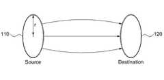
- FIG. 1is a diagram illustrating a wireless power transfer system including resonators for wireless power transfer.
- FIG. 2is a view showing a two-dimensional resonator in accordance with an embodiment of the present invention.
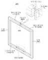
- FIG. 3is a view showing a three-dimensional resonator in accordance with an embodiment of the present invention.
- FIG. 4is a diagram illustrating an example of a resonator for wireless power transmission designed as a bulky type.
- FIG. 5is a diagram illustrating an example of a resonator for wireless power transmission designed in a hollow type.
- FIG. 6is a diagram illustrating an example of a resonator for wireless power transmission to which a parallel-sheet is applied.
- FIG. 7illustrates an example of a resonator for wireless power transmission including distributed capacitors.
- FIG. 8is a diagram illustrating examples of matchers used in a two-dimensional resonator and a three-dimensional resonator.
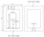
- FIG. 9is a diagram illustrating a first unit resonator and a second unit resonator included in a split ring type resonator for wireless power transmission.
- FIG. 10is a three-dimensional view of a split ring resonator.
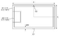
- FIG. 11is a diagram illustrating a split ring type resonator including two unit resonators having different sizes.
- FIG. 12illustrates a resonator for wireless power transmission having a plurality of turns in a horizontal direction.
- FIG. 13illustrates a resonator for wireless power transmission having a plurality of turns in a vertical direction.
- FIG. 14illustrates a resonator for wireless power transmission including a large unit resonator and small unit resonators positioned inside a loop of the large unit resonator.
- FIG. 15illustrates a three-dimensional resonator for wireless power transmission having omnidirectional characteristics.
- FIG. 16is a diagram illustrating an equivalent circuit of the resonator for wireless power transmission shown in FIG. 2.
- FIG. 17is a diagram illustrating an equivalent circuit of a composite right-left handed transmission lime having a zeroth resonance characteristic.
- FIG. 18is a graph conceptually illustrating a zero-order resonance occurring in a mixed right-left transmission line.
- 19is a table showing characteristics of a resonator for wireless power transmission according to an embodiment of the present invention.
- 20 to 22illustrate various implementations of a resonator for wireless power transmission according to an embodiment of the present invention.
- FIG. 23is a block diagram illustrating a wireless power transmission apparatus that may be applied to the source illustrated in FIG. 1.
- FIG. 24is a block diagram illustrating an apparatus for receiving power wirelessly, which may be applied to the destination illustrated in FIG. 1.
- FIG. 1is a diagram illustrating a wireless power transmission system including a resonator for wireless power transmission and a resonator for wireless power reception.
- FIG. 1illustrates a wireless power transfer system utilizing resonance characteristics includes a source 110 and a destination 120.
- the source 110wirelessly supplies power to the destination 120 by using a helix coil structure resonator or a spiral coil structure resonator.
- the physical size of the resonator of the helix coil structure or the resonator of the spiral coil structuredepends on the desired resonant frequency. For example, when the desired resonant frequency is 10Mhz, the diameter of the resonator of the helix coil structure is about 0.6m, and the diameter of the resonator of the spiral coil structure is also set to about 0.6m. At this time, the diameter of the resonator of the helix coil structure and the resonator of the spiral coil structure should increase as the desired resonant frequency decreases.
- the physical size of the resonatorit is not ideal for the physical size of the resonator to change as the resonant frequency changes.
- the size of the resonatormay be very large, which may not be practical.
- the resonant frequency and the size of the resonatorare independent of each other.
- a resonator capable of operating well while having a reasonable physical sizemay be ideal for both a high resonant frequency and a low resonant frequency.
- Permeabilityrefers to the ratio of the magnetic flux density occurring for a given magnetic field in a material and the magnetic flux density occurring for that field in vacuum.
- dielectric constantrefers to a ratio of electric flux density generated for a given electric field in the material and electric field flux density generated for the electric field in vacuum.
- Permeability and permittivitydetermine the propagation constant of the material at a given frequency or wavelength, and the permeability and permittivity determine the electromagnetic properties of the material.
- metamaterialsmaterials with dielectric constants or permeabilities that do not exist in nature and which are artificially designed are called metamaterials, and metamaterials are readily available even at very large wavelengths or at very low frequency ranges (ie, the size of the material does not change much). Can be placed in a resonant state.
- FIG. 2is a view showing a two-dimensional resonator in accordance with an embodiment of the present invention.
- a resonator having a two-dimensional structureincludes a transmission line including a first signal conductor portion 211, a second signal conductor portion 212, and a ground conductor portion 213.
- the capacitor 220is inserted in series at a position between the first signal conductor portion 211 and the second signal conductor portion 212 in the transmission line, so that the electric field is It is trapped in the capacitor 220.
- the transmission lineincludes at least one conductor on the top and at least one conductor on the bottom, current flows through the conductor on the top, and the conductor on the bottom is electrically grounded.
- a conductor in the upper portion of the transmission lineis divided into a first signal conductor portion 211 and a second signal conductor portion 212, and a conductor in the lower portion of the transmission line is referred to as a ground conductor portion 213. .
- the resonator 200has a form of a two-dimensional structure.
- the transmission lineincludes a first signal conductor portion 211 and a second signal conductor portion 212 at the top and a ground conductor portion 213 at the bottom.
- the first signal conductor portion 211, the second signal conductor portion 212 and the ground conductor portion 213are disposed to face each other. Current flows through the first signal conductor portion 211 and the second signal conductor portion 212.
- one end of the first signal conductor portion 211is shorted with the conductor 242, and the other end thereof is connected with the capacitor 220.
- One end of the second signal conductor portion 212is grounded with the conductor 241, and the other end thereof is connected with the capacitor 220.
- the first signal conductor portion 211, the second signal conductor portion 212, the ground conductor portion 213, and the conductors 241 and 242are connected to each other, whereby the resonator 200 is electrically closed.
- the 'loop structure'includes a circular structure, a polygonal structure such as a square, and the like, and 'having a loop structure' means that the electrical structure is closed.
- the capacitor 220is inserted in the interruption of the transmission line. More specifically, capacitor 220 is inserted between first signal conductor portion 211 and second signal conductor portion 212.
- the capacitor 220may have a form such as a lumped element and a distributed element.
- a distributed capacitor in the form of a dispersing elementmay comprise zigzag conductor lines and a dielectric having a high dielectric constant between the conductor lines.
- the resonator 200may have a metamaterial characteristic.
- the metamaterialis a material having special electrical properties that cannot be found in nature, and has an artificially designed structure.
- the electromagnetic properties of all materials in naturehave inherent permittivity or permeability, and most materials have positive permittivity and positive permeability. In most materials, the right-hand rule applies to electric, magnetic and pointing vectors, so these materials are called Right Handed Material (RHM).
- RHMRight Handed Material
- meta-materialsare materials that have a permittivity or permeability that does not exist in nature. index) substances, LH (left-handed) substances and the like.
- the resonator 200may have a metamaterial characteristic.
- the resonator 200since the resonator may have a negative permeability, the resonator 200 according to an embodiment of the present invention may be referred to as an MNG resonator.
- the criterions for determining the capacitance of the capacitor 220may vary.
- a premise that allows the resonator 200 to have properties of metamateriala premise that the resonator 200 has a negative permeability at the target frequency, or the resonator 200 is zero at the target frequency.
- Theremay be a premise for having a resonance (Zeroth-Order Resonance) characteristic, and the capacitance of the capacitor 220 may be determined under at least one of the above-described preconditions.
- the MNG resonator 200may have a zero-order resonance characteristic having a frequency when the propagation constant is 0 as a resonance frequency. Since the MNG resonator 200 may have a zeroth resonance characteristic, the resonant frequency may be independent of the physical size of the MNG resonator 200. That is, as will be described again below, in order to change the resonant frequency in the MNG resonator 200, it is sufficient to properly design the capacitor 220, so that the physical size of the MNG resonator 200 may not be changed.
- the MNG resonator 200may have a high Q-factor by using the capacitor 220 of the lumped element, the efficiency of power transmission may be improved.
- the cue-factorindicates the degree of ohmic loss or the ratio of reactance to resistance in wireless power transmission. The larger the cue-factor, the greater the efficiency of wireless power transmission. .
- the MNG resonator 200may include a matcher 230 for impedance matching.
- the matcher 230can tunably adjust the strength of the magnetic field of the MNG resonator 200, and the impedance of the MNG resonator 200 is determined by the matcher 230.
- the currentmay flow into the MNG resonator 200 through the connector 240 or flow out of the MNG resonator 200.
- the connector 240may be connected to the ground conductor portion 213 or the matcher 230.
- a physical connectionmay be formed between the connector 240 and the ground conductor part 213 or the matcher 230, and may be a physical connection between the connector 240 and the ground conductor part 213 or the matcher 230. Power may be delivered through the coupling without a phosphorous connection.
- the matcher 230may be located inside a loop formed due to the loop structure of the resonator 200.
- the matcher 230may adjust the impedance of the resonator 200 by changing the physical shape.
- the matcher 230may include a conductor 231 for impedance matching at a distance h from the ground conductor portion 213, and the impedance of the resonator 200 may be changed by adjusting the distance h. have.
- the matcher 230may change the physical form of the matcher 230 according to a control signal generated by the controller. have. For example, the distance h between the conductor 231 of the matcher 230 and the ground conductor portion 213 may be increased or decreased in accordance with the control signal, thereby changing the physical shape of the matcher 230. As a result, the impedance of the resonator 200 may be adjusted.
- the controllermay generate a control signal in consideration of various factors, which will be described below.
- the matcher 230may be implemented as a passive element such as the conductor portion 231, and in some embodiments, may be implemented as an active element such as a diode or a transistor.
- the active elementWhen the active element is included in the matcher 230, the active element may be driven according to a control signal generated by the controller, and the impedance of the resonator 200 may be adjusted according to the control signal.
- the matcher 230may include a diode, which is a kind of active element, and the impedance of the resonator 200 may be adjusted according to whether the diode is in an 'on' state or an 'off' state.
- a magnetic core penetrating the MNG resonator 200may be further included. Such a magnetic core may perform a function of increasing a power transmission distance.
- FIG. 3is a view showing a three-dimensional resonator in accordance with an embodiment of the present invention.
- a three-dimensional resonator 200includes a first signal conductor portion 211, a second signal conductor portion 212, and a ground conductor portion 213. Transmission line and capacitor 220.
- the capacitor 220is inserted in series at a position between the first signal conductor portion 211 and the second signal conductor portion 212 in the transmission line, and the electric field is trapped in the capacitor 220.
- the resonator 200has a three-dimensional structure.
- the transmission lineincludes a first signal conductor portion 211 and a second signal conductor portion 212 at the top and a ground conductor portion 213 at the bottom.
- the first signal conductor portion 211, the second signal conductor portion 212 and the ground conductor portion 213are disposed to face each other.
- the currentflows in the x direction through the first signal conductor portion 211 and the second signal conductor portion 212, and this current generates a magnetic field H (w) in the y direction.
- a magnetic field H (w)may occur in the + y direction.
- the 'loop structure'includes a circular structure, a polygonal structure such as a square, and the like, and 'having a loop structure' means that the electrical structure is closed.
- the capacitor 220is inserted between the first signal conductor portion 211 and the second signal conductor portion 212.
- the capacitor 220may have a form such as a lumped element and a distributed element.
- a distributed capacitor in the form of a dispersing elementmay comprise zigzag conductor lines and a dielectric having a high dielectric constant between the conductor lines.
- the resonator 200may have a metamaterial characteristic.
- the resonator 200may have a metamaterial characteristic.
- the resonator 200may have a negative permeability in a specific frequency band, the resonator 200 according to an embodiment of the present invention may be referred to as an MNG resonator.
- the criterions for determining the capacitance of the capacitor 220may vary.
- a premise that allows the resonator 200 to have properties of metamateriala premise that the resonator 200 has a negative permeability at the target frequency, or the resonator 200 is zero at the target frequency.
- the MNG resonator 200 illustrated in FIG. 3may have a zero-order resonance characteristic having a frequency when the propagation constant is 0 as a resonance frequency. Since the MNG resonator 200 may have a zeroth resonance characteristic, the resonant frequency may be independent of the physical size of the MNG resonator 200. In order to change the resonant frequency in the MNG resonator 200, it is sufficient to design the capacitor 220 appropriately, so that the physical size of the MNG resonator 200 may not be changed.
- the MNG resonator 200in the near field (near field) electric field is concentrated in the capacitor 220 inserted into the transmission line 210, due to the capacitor 220 in the near field The magnetic field is dominant.
- the MNG resonator 200 having the zeroth-order resonance characteristichas characteristics similar to the magnetic dipole, the magnetic field is dominant in the near field and is generated due to the insertion of the capacitor 220. Since a small amount of electric field is also concentrated on the capacitor 220, the magnetic field becomes even more dominant in the near field. Since the MNG resonator 200 may have a high Q-factor using the capacitor 220 of the lumped device, the MNG resonator 200 may improve the efficiency of power transmission.
- the MNG resonator 200 illustrated in FIG. 3may include a matcher 230 for impedance matching.
- the matcher 230can properly adjust the strength of the magnetic field of the MNG resonator 200, and the impedance of the MNG resonator 200 is determined by the matcher 230.
- the currentflows into the MNG resonator 200 through the connector 240 or flows out of the MNG resonator 200.
- the connector 240may be connected to the ground conductor portion 213 or the matcher 230.
- the matcher 230may be located inside a loop formed due to the loop structure of the resonator 200.
- the matcher 230may adjust the impedance of the resonator 200 by changing the physical shape.
- the matcher 230may include a conductor portion 231 for impedance matching at a position separated by a distance h from the ground conductor portion 213, and the impedance of the resonator 200 may be changed by adjusting the distance h. Can be.
- the matcher 230may change the physical form of the matcher 230 according to a control signal generated by the controller. have. For example, the distance h between the conductor 231 of the matcher 230 and the ground conductor portion 230 may be increased or decreased in accordance with the control signal, thereby changing the physical shape of the matcher 230. As a result, the impedance of the resonator 200 may be adjusted.
- the distance h between the conductor 231 and the ground conductor portion 230 of the matcher 230can be adjusted in various ways. That is, first, the matcher 230 may include several conductors, and the distance h may be adjusted by adaptively activating any one of the conductors.
- the distance hcan be adjusted. This distance h may be controlled according to the control signal of the controller, and the controller may generate the control signal in consideration of various factors.
- the controllergenerates a control signal is described below.
- the matcher 230may be implemented as a passive element such as the conductor portion 231, and in some embodiments, may be implemented as an active element such as a diode or a transistor.
- the active elementWhen the active element is included in the matcher 230, the active element may be driven according to a control signal generated by the controller, and the impedance of the resonator 200 may be adjusted according to the control signal.
- the matcher 230may include a diode, which is a kind of active element, and the impedance of the resonator 200 may be adjusted according to whether the diode is in an 'on' state or an 'off' state.
- a magnetic core penetrating the MNG resonator 200may be further included. Such a magnetic core may perform a function of increasing a power transmission distance.
- FIG. 4is a diagram illustrating an example of a resonator for wireless power transmission designed as a bulky type.
- first signal conductor portion 211 and the conductor 242may be manufactured separately and then manufactured as a single piece instead of being connected to each other.
- second signal conductor portion 212 and conductor 241may also be fabricated in one piece.
- the second signal conductor portion 212 and the conductor 241are separately fabricated and then connected to each other, there may be conductor losses due to the seam 250.
- the second signal conductor portion 212 and the conductor 241are seamlessly connected to each other, and the conductor 241 and the ground conductor portion 213 are also separated. They can be connected together without a seam, reducing conductor losses due to seams.
- the second signal conductor portion 212 and the ground conductor portion 213can be fabricated as a single piece without a separate seam.
- the first signal conductor portion 211 and the ground conductor portion 213can be fabricated as a single piece without a separate seam.
- the type of connecting two or more partitions to each other as one unit without a separate seamlessis also called a 'bulky type'.
- FIG. 5is a diagram illustrating an example of a resonator for wireless power transmission designed in a hollow type.
- the active currentflows through all portions of each of the first signal conductor portion 211, the second signal conductor portion 212, the ground conductor portion 213, and the conductors 241, 242. Rather, it can be modeled as flowing through only a portion of it. That is, at a given resonance frequency, the first signal conductor portion 211, the second signal conductor portion 212, the ground conductor portion 213, and the conductors 241, 242 have a thickness greater than their respective skin depths. Thick ones can be inefficient. That is, it may cause the weight of the resonator 200 or the manufacturing cost of the resonator 200 to increase.
- the skin depth of each of the first signal conductor portion 211, the second signal conductor portion 212, the ground conductor portion 213, and the conductors 241, 242 at a given resonance frequencymay be appropriately determined based on the above.
- the resonator 200may be used. May be light, and the manufacturing cost of the resonator 200 may also be reduced.
- the thickness of the second signal conductor portion 212can be defined as dm, and d is It can be determined through.
- fis the frequency
- Is the permeabilityRepresents a conductor constant.
- the first signal conductor portion 211, the second signal conductor portion 212, the ground conductor portion 213, and the conductors 241, 242are copper and have a conductivity of 5.8 ⁇ 10 7.
- the skin depthmay be about 0.6 mm for the resonant frequency of 10 kHz, and the skin depth may be 0.006 mm for the resonant frequency of 100 MHz.
- FIG. 6is a diagram illustrating an example of a resonator for wireless power transmission to which a parallel-sheet is applied.
- a parallel-sheetmay be applied to surfaces of each of the first signal conductor part 211 and the second signal conductor part 212 included in the resonator for wireless power transmission to which the parallel-sheet is applied.
- first signal conductor portion 211 and the second signal conductor portion 212are not perfect conductors, they may have resistive components, and ohmic losses may occur due to the resistive components. . This resistance loss can reduce the Q factor and reduce the coupling efficiency.
- each of the first signal conductor part 211 and the second signal conductor part 212includes a plurality of conductor lines. These conductor lines are arranged in parallel and are grounded at the ends of each of the first signal conductor portion 211 and the second signal conductor portion 212.
- FIG. 7is a diagram illustrating an example of a resonator for wireless power transmission including a distributed capacitor.
- the capacitor 220 included in the resonator for wireless power transmissionmay be a distributed capacitor.
- the capacitor as a lumped elementmay have a relatively high equivalent series resistance (ESR).
- ESRequivalent series resistance
- the capacitor 220 as the dispersing elementmay have a zigzag structure, as shown in FIG. 7. That is, the capacitor 220 as the dispersing element may be implemented with a conductor line and a dielectric having a zigzag structure.
- the embodiment of the present inventionnot only reduces the loss due to ESR by using the capacitor 220 as the dispersing element, but also uses the capacitors as a plurality of lumped elements in parallel. By doing so, losses due to ESR can be reduced. Because the resistive components of each of the capacitors as the lumped element are reduced through parallel connection, the effective resistance of the capacitors as the lumped element connected in parallel can also be reduced, thus reducing the loss due to the ESR. For example, by replacing one capacitor of 10 pF with one capacitor of 10 pF, the loss due to ESR can be reduced.
- FIG. 8is a diagram illustrating examples of matchers used in a two-dimensional resonator and a three-dimensional resonator.
- FIG. 8Aillustrates a portion of the two-dimensional resonator shown in FIG. 2 including a matcher
- FIG. 8Billustrates a portion of the three-dimensional resonator shown in FIG. 3 including a matcher.
- the matcherincludes a conductor 231, a conductor 232, and a conductor 233, where the conductor 232 and the conductor 233 comprise the ground conductor portion 213 and the conductor ( 231).
- the impedance of the two-dimensional resonatoris determined according to the distance h between the conductor 231 and the ground conductor portion 213, and the distance h between the conductor 231 and the ground conductor portion 213 is controlled by the controller.
- the distance h between the conductor 231 and the ground conductor portion 213can be adjusted in a variety of ways, adjusting the distance h by adaptively activating any one of the various conductors that can be the conductor 231. Method, a method of adjusting the distance h by adjusting the physical position of the conductor 231 up and down.
- the matcherincludes a conductor 231, a conductor 232, and a conductor 233, where the conductor 232 and the conductor 233 comprise the ground conductor portion 213 and the conductor ( 231).
- the impedance of the three-dimensional resonatoris determined according to the distance h between the conductor 231 and the ground conductor portion 213, and the distance h between the conductor 231 and the ground conductor portion 213 is controlled by the controller.
- the distance h between the conductor 231 and the ground conductor portion 213can be adjusted in various ways. For example, a method of adjusting the distance h by adaptively activating any one of the various conductors that may be the conductor 231, and adjusting the distance h by adjusting the physical position of the conductor 231 up and down. And the like.
- the matchermay include an active element, and the method of adjusting the impedance of the resonator using the active element is similar to that described above. That is, the impedance of the resonator may be adjusted by changing the path of the current flowing through the matcher using the active element.
- FIG. 9is a diagram illustrating a first unit resonator and a second unit resonator included in a split ring type resonator for wireless power transmission.
- each of the first unit resonator 21 and the second unit resonator 22 included in the split ring resonatorincludes a transmission line and a capacitor inserted in series at a stop of the transmission line.
- the first unit resonator 21may include a matcher having a thickness e and a height c
- the second unit resonator 22may further include a matcher as shown in FIG. 9.
- the matcher included in the first unit resonator 21 and the matcher included in the second unit resonator 22may be connected to each other through vias.
- both of the two unit resonators 21 and 22may operate together.
- the vertical length of the first unit resonator 21 of FIG. 9is 'a'
- the horizontal length of the first unit resonator 21is 'b'
- the thickness of the transmission lineis 'd'
- the matcherThe vertical length of is 'c' and the thickness of the matcher is 'e'.
- amay be in the range of about 50 mm to 70 mm
- bis about 30 mm to 50 mm
- cis 4 mm to 4.6 mm
- dis 4.5 mm to 5.5 mm
- eis 1.7 mm to 2.3 mm.
- amay be 60 mm
- bmay be 40 mm
- cmay be 4.3 mm
- dmay be 5 mm
- emay be 2 mm.
- the sizes of a, b, c, d and e described aboveare merely examples. That is, the case where the size of a is larger than 70 mm can be easily considered.
- the value of hcan be adaptively adjusted according to the desired resonance frequency and the like.
- the first unit resonator 21 and the second unit resonator 22 of FIG. 9may be stacked in two layers, and include the first unit resonator 21 and the second unit resonator 22 in two layers.
- the resonatorcan be called a split ring type resonator.
- the first unit resonator 21may be located in one plane, and the second unit resonator 22 may be located in another plane away from the plane by a predetermined distance.
- the length of the outer circumference of the first unit resonator 21 and the length of the outer circumference of the second unit resonator 22 shown in FIG. 9are the same, and the area of the inner loop of the first unit resonator 21 When the inner loops of the second unit resonator 22 have the same area, mutual coupling may be maximized between the first unit resonator 21 and the second unit resonator 22.
- the capacitor of the first unit resonator 21 and the capacitor of the second unit resonator 22 illustrated in FIG. 9may be inserted in the same direction or may be inserted in the opposite direction.
- a case in which the capacitor of the first unit resonator 21 and the capacitor of the second unit resonator 22 are inserted in opposite directionswill be described in detail with reference to FIG. 10.
- Fig. 10is a three-dimensional view showing a split ring type resonator.
- a second unit resonator 22is disposed below the first unit resonator 21, and the split ring type resonator has two layers and includes a first unit resonator 21 and a second unit resonator ( 22).
- the capacitor of the first unit resonator 21 and the capacitor of the second unit resonator 22may be inserted in opposite directions. However, unlike FIG. 10, the capacitor of the first unit resonator 21 and the capacitor of the second unit resonator 22 may be inserted in the same direction.
- the length of the outer circumference of the first unit resonator 21 and the length of the outer circumference of the second unit resonator 22are the same, and the area of the inner loop of the first unit resonator 21 is the same. If the area of the inner loop of the second unit resonator 22 and the same area, mutual coupling (mutual coupling) can be maximized between the first unit resonator 21 and the second unit resonator 22.
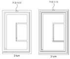
- FIG. 11illustrates a split ring type resonator including two unit resonators having different sizes.
- the split ring type resonatorincludes a first unit resonator 21 and a second unit resonator 22 having different sizes. That is, in the split ring type resonator, the second unit resonator 22 is included in the loop of the first unit resonator 21. In this case, the first unit resonator 21 and the second unit resonator 220 may be disposed on the same plane or may be disposed on another plane.
- C1represents a capacitor inserted into the first unit resonator 21
- C2represents a capacitor inserted into the second unit resonator 22.
- FIG. 12illustrates a resonator for wireless power transmission having a plurality of turns in a horizontal direction.
- a resonator for wireless power transmission having a plurality of turns in a horizontal directionincludes a plurality of turns formed in a horizontal direction. More specifically, referring to the resonator including two turns shown in FIG. 12, the upper conductors represent the first signal conductor portion and the second signal conductor portion included in the transmission line, and the lower conductors are the transmission line. Indicates the part of the ground conductor included in.
- the conductors on the left sideare first conductors connecting the first signal conductor portion and the ground conductor portion, and the conductors on the right side may be viewed as second conductors connecting the second signal conductor portion and the ground conductor portion.
- the first signal conductor portion, the second signal conductor portion, the first conductor and the second conductorinclude two turns.
- the first signal conductor portion, the second signal conductor portion, the first conductor and the second conductor included in the resonatorinclude three turns. It can be seen.
- the size of each of the turnsmay be the same or may be different.
- the turnsmay be considered to be formed in the horizontal direction, and due to the plurality of turns formed in the horizontal direction, the inductance value of the resonator may increase.
- the capacitance of the capacitor relative to its inductancebecomes relatively small. Therefore, the influence of the ESR can be reduced, and the resonator for wireless power transmission having such a plurality of turns can be well applied to a mobile device such as a cellular phone.
- FIG. 13illustrates a resonator for wireless power transmission having a plurality of turns in a vertical direction.
- the resonator for having a plurality of turns in the vertical directionmay include the resonator shown in FIG. 2.
- a plurality of turnsare formed in the vertical direction. It can be seen.
- the plurality of turnsare electrically connected to each other.
- each of the plurality of turnsis on a different plane.
- the sizes of the turnsmay be the same or different.
- the plurality of turnsmay be considered to be formed in the vertical direction, and the resonator for wireless power transmission having the plurality of turns in the vertical direction has a three-layer structure. have. Due to this three-layer structure, the inductance can be increased for a given cross-sectional area, and the capacitance of the capacitor can be made relatively small.
- the resonatoris less affected by ESR and can be applied well to mobile devices such as cell phones.
- the resonator illustrated in FIG. 13may minimize the influence on the surrounding environment as compared with the resonator for wireless power transmission having a plurality of turns in the horizontal direction illustrated in FIG. 12.
- the plurality of turns shown in FIGS. 12 and 13may be grounded to one ground plane.
- the resistance losscan be minimized, thus improving the cue factor.
- FIG. 14illustrates a resonator for wireless power transmission including a large unit resonator and small unit resonators positioned inside a loop of the large unit resonator.
- the resonator for wireless power transmissionincludes six first unit resonators having a length a and a length b and six second unit resonators having a size smaller than that of the first unit resonator.
- the number of second unit resonatorsmay vary.
- the six second unit resonatorsare positioned inside the loop of the first unit resonator and are regularly arranged at a specific interval within the loop of the one unit resonator.
- amay be about 260 mm
- bmay be about 150 mm
- cmay be about 27.5 mm
- dmay be about 16.7 mm.
- the resonator shown in FIG. 14can have a high effective mu and can increase the power transfer gain. This is because the second unit resonator functions to effectively increase the permeability of the first unit resonator, which may increase the permeability of the overall resonator shown in FIG. 14. According to the resonator illustrated in FIG. 14, the effective permeability may be increased by using the arrangement of the first unit resonator and the second unit resonator, rather than increasing the permeability depending on the material.
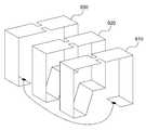
- FIG. 15illustrates a three-dimensional resonator for wireless power transmission having omnidirectional characteristics.
- the magnetic field of the first unit resonator and the magnetic field of the second unit resonatorare formed in different directions.
- the magnetic field by the first unit resonator and the magnetic field by the second unit resonatorare orthogonal, the magnetic fields are not coupled to each other.
- the resonator 1 of FIG. 15can transmit power omnidirectionally.
- each of the six surfaces included in the cubecorresponds to a unit resonator.
- the resonator 2 of FIG. 15may not only transmit power omnidirectionally but also adaptively adjust the strength of the magnetic field.
- the resonator according to the embodiment of the present inventionmay have a structure of the resonator 3 of FIG. 15, and such a resonator may also transmit power in all directions.
- the resonator according to the embodiment of the present inventionmay have a spherical structure, as shown in the resonator 4 of FIG. 15.
- the outer edge of the spheremay be surrounded by transmission lines, and a cross feeder may be positioned inside the sphere.
- Cross feedersinclude a plurality of feeders, and power may be transmitted in a direction corresponding to an activated feeder among the plurality of feeders. In particular, when all feeders are activated, power can be transmitted in all directions.
- FIG. 16is a diagram illustrating an equivalent circuit of the resonator for wireless power transmission shown in FIG. 2.
- the resonator for wireless power transmission shown in FIG. 2may be modeled with the equivalent circuit shown in FIG. 16.
- C Lrepresents a capacitor inserted in the form of a lumped element in the middle of the transmission line of FIG. 2.
- the resonator for wireless power transmission shown in FIG. 2has a zeroth resonance characteristic. That is, when the propagation constant is 0, the resonator for wireless power transmission Suppose we have a resonant frequency. At this time, the resonance frequency May be expressed as Equation 1 below.
- MZRmeans Mu Zero Resonator.
- the resonant frequency of the resonator IsCan be determined by the resonant frequency It can be seen that the physical size of the and the resonator may be independent of each other. Thus, resonant frequency Since the physical sizes of the and resonators are independent of each other, the physical sizes of the resonators can be sufficiently small.
- FIG. 17is a diagram illustrating an equivalent circuit of a composite right-left handed transmission lime having a zeroth resonance characteristic.
- a resonator for wireless power transmission according to embodiments of the present inventionis based on an MNG transmission line, the MNG transmission line will be described through a mixed right-left transmission line.
- the equivalent circuit of the mixed right-left transmission lineis a series-capacitor compared to the basic transmission line.
- 411 and 421denotes an inductor component and a capacitor component of the basic transmission line.
- the impedance Z '410is A component corresponding to 411 and Is the sum of the components corresponding to 412
- the admittance Y '420is A component corresponding to 421 and It is the sum of the components corresponding to 422.
- Equation 2the impedance Z '410 and the admittance Y' 420 can be expressed by Equation 2 below.
- the resonant frequency(the amplitude of the impedance Z '410 or the admittance Y' 420 at the resonant frequency is minimum) is applied to the basic transmission line. 412 and By appropriately adding 422, it can be seen that the mixed right-left transmission line has a zeroth resonance characteristic. That is, the resonance frequency of the mixed right-left transmission line may be a frequency when the propagation constant is zero.
- transmission linesOn the basic transmission line If only 412 is added, such transmission lines have a negative permeability in a particular frequency band and are therefore called MNG transmission lines. Also, If only 422 is added, such transmission lines have a negative dielectric constant and are therefore called ENG transmission lines, and MNG transmission lines and ENG transmission lines also have zero resonant characteristics.
- the MNG resonatorallows the magnetic field to be dominant in the near field. 412.
- the electric field in the near fieldis Focused at 412, the magnetic field is dominant in the near field.
- the MNG resonatorsince the MNG resonator has a zeroth resonance characteristic like the mixed right-left transmission line, the MNG resonator can be made small regardless of the resonance frequency.
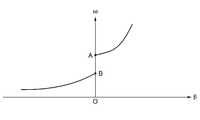
- FIG. 18is a graph conceptually illustrating a zero-order resonance occurring in a mixed right-left transmission line.
- the mixed right-left transmission linehas A and B as resonant frequencies. At this time, since the propagation constant (beta) corresponding to A and B is 0, the mixed right-left transmission line has a zeroth resonance characteristic.
- the MNG transmission line and the ENG transmission linealso have zero resonance characteristics.
- the resonance frequency of the MNG transmission linemay be A
- the resonance frequency of the ENG transmission linemay be B. Therefore, the MNG resonator according to embodiments of the present invention can be manufactured in a sufficiently small size.
- 19is a table showing characteristics of a resonator for wireless power transmission according to an embodiment of the present invention.
- a magnetic fieldis dominant relative to an electric field in a near field of an MNG resonator according to embodiments of the present invention.
- the MNG resonatormay improve power transmission efficiency through magnetic field coupling.
- the MNG resonator according to the embodiments of the present inventionmay be manufactured in a three-dimensional structure, and aims at a high cue factor.
- the MNG resonator according to embodiments of the present inventionis used for short-range wireless power transmission.
- 20 to 22illustrate various implementations of a resonator for wireless power transmission according to an embodiment of the present invention.
- a resonator for wireless power transmissionincludes a plurality of transmission lines 710, 720, and 730 connected in series with each other.
- each of the plurality of capacitors 711, 721, and 731is inserted into each of the plurality of transmission lines 710, 720, and 730.
- a resonator for wireless power transmissionmay have a spiral structure. That is, the plurality of transmission lines are connected to each other in a spiral structure, and each of the plurality of capacitors may be inserted into each of the plurality of transmission lines.
- a resonator for wireless power transmissionmay include a plurality of transmission lines 910, 920, and 930 connected in parallel.
- a resonator for wireless power transmissionmay be manufactured in various forms.
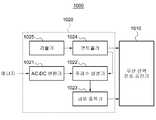
- FIG. 23is a block diagram illustrating a wireless power transmission apparatus that may be applied to the source illustrated in FIG. 1.
- the wireless power transmitter 1000includes a wireless power transmission resonator 1010 and a preprocessor 1020.
- the wireless power transfer resonator 1010may be the resonator described with reference to FIGS. 1 through 22, and the power is wirelessly transmitted by a wave propagated by the wireless power transfer resonator 1010.
- the preprocessor 1020generates a current and a frequency for wireless power transmission by using energy supplied from an external or internal power supply of the wireless power transmitter 1000.
- the preprocessor 1020includes an AC-DC converter 1021, a frequency generator 1022, a power amplifier 1023, a controller 1024, and a detector 1025.
- the AC-DC converter 1021converts alternating current (AC) energy supplied from a power supply into direct current (DC) energy or direct current.
- the frequency generator 1022generates a desired frequency (ie, resonant frequency) according to the DC energy or the DC current, and generates a current having the desired frequency.
- the current with the desired frequencymay be amplified by the amplifier 1023.
- the controller 1024generates a control signal for adjusting the impedance of the wireless power transmission resonator 1010 and adjusts the frequency generated by the frequency generator 1022. For example, among the various frequency bands, an optimal frequency for maximizing power transmission gain and coupling efficiency may be selected.
- the detector 1025is a distance between the wireless power transmission resonator 1010 and the wireless power reception resonator of the wireless power receiver, a wave radiated from the wireless power transmission resonator 1010 to the wireless power reception resonator. ), A power transmission gain between the wireless power transmission resonator 1010 and the wireless power reception resonator, or a coupling efficiency between the wireless power transmission resonator 1010 and the wireless power reception resonator.
- the controller 1024adjusts the impedance of the wireless power transmission resonator 1010 or adjusts the frequency generated by the frequency generator 1022 in consideration of the distance, the reflection coefficient, the power transmission gain, and the coupling efficiency. Can generate a control signal.
- FIG. 24is a block diagram illustrating an apparatus for receiving power wirelessly, which may be applied to the destination illustrated in FIG. 1.
- the wireless power receiver 1100includes a wireless power reception resonator 1110, a rectifier 1120, a rectifier, a detector 1130, and a controller 1140.
- the wireless power reception resonator 1110may be the resonator described with reference to FIGS. 1 to 22, and receives a wave propagated by the wireless power transmission device.
- Rectifier 1120converts power from the received wave into direct current energy, all or part of which is provided to the target device.
- the detector 1130is a distance between the wireless power transmission resonator and the wireless power reception resonator 1110 of the wireless power receiver 1100, and radiates from the wireless power transmission resonator to the wireless power reception resonator 1100.
- the controller 1140may radiate a distance between the wireless power transmission resonator and the wireless power reception resonator 1110 of the wireless power reception resonator 1100, from the wireless power transmission resonator to the wireless power reception resonator 1100.
- a reflection coefficient of a wave, a power transmission gain between the wireless power transmission resonator and the wireless power reception resonator 1100, or a coupling efficiency between the wireless power transmission resonator and the wireless power reception resonator 1100, and the like.Generate a control signal for adjusting the impedance of the wireless power receiving resonator on the basis.
Landscapes
- Engineering & Computer Science (AREA)
- Computer Networks & Wireless Communication (AREA)
- Power Engineering (AREA)
- Control Of Motors That Do Not Use Commutators (AREA)
- Transmitters (AREA)
- Charge And Discharge Circuits For Batteries Or The Like (AREA)
- Support Of Aerials (AREA)
- Filters And Equalizers (AREA)
- Details Of Aerials (AREA)
- Near-Field Transmission Systems (AREA)
Abstract
Description
Translated fromKorean아래의 실시예들은 무선 전력 전송 시스템에 관한 것으로, 특히 무선 전력 전송 시스템을 위한 공진기를 설계하는 기술에 관한 것이다.The following embodiments relate to wireless power transfer systems, and more particularly to techniques for designing resonators for wireless power transfer systems.
무선 전력 전송 기술들 중 하나는 RF 소자들의 공명(resonance) 특성을 이용한다. 코일 구조를 사용하는 공명기는 주파수에 따라 물리적 사이즈의 변화가 필요하다.One of the wireless power transfer technologies takes advantage of the resonance characteristics of RF devices. Resonators using a coil structure require a change in physical size with frequency.
본 발명의 일실시예에 따른 무선 전력 공진기는 적어도 두 개의 단위 공진기들을 포함한다. 여기서, 상기 적어도 두 개의 단위 공진기들 각각은 제1 신호 도체 부분 및 제2 신호 도체 부분과, 상기 제1 신호 도체 부분 및 상기 제2 신호 도체 부분에 대응되는 그라운드 도체 부분을 포함하는 전송 선로; 상기 제1 신호 도체 부분과 상기 그라운드 도체 부분을 전기적으로 연결하는 제1 도체; 상기 제2 신호 도체 부분과 상기 그라운드 도체 부분을 전기적으로 연결하는 제2 도체; 및 상기 제1 신호 도체 부분 및 상기 제2 신호 도체 부분을 흐르는 전류에 대하여 직렬로 상기 제1 신호 도체 부분 및 상기 제2 신호 도체 부분 사이에 삽입되는 적어도 하나의 커패시터를 포함한다.The wireless power resonator according to an embodiment of the present invention includes at least two unit resonators. Each of the at least two unit resonators may include a transmission line including a first signal conductor portion and a second signal conductor portion, and a ground conductor portion corresponding to the first signal conductor portion and the second signal conductor portion; A first conductor electrically connecting the first signal conductor portion and the ground conductor portion; A second conductor electrically connecting the second signal conductor portion and the ground conductor portion; And at least one capacitor inserted between the first signal conductor portion and the second signal conductor portion in series with respect to the current flowing through the first signal conductor portion and the second signal conductor portion.
상기 전송 선로, 상기 제1 도체 및 상기 제2 도체는 루프 구조를 형성할 수 있다.The transmission line, the first conductor and the second conductor may form a loop structure.
상기 적어도 두 개의 단위 공진기들은 제1 단위 공진기 및 제2 단위 공진기를 포함하고, 상기 제1 단위 공진기는 상위 평면에 위치하고, 상기 제2 단위 공진기는 하위 평면에 위치하며, 상기 상위 평면 및 상기 하위 평면은 소정의 거리만큼 떨어져 있을 수 있다.The at least two unit resonators include a first unit resonator and a second unit resonator, the first unit resonator is located in an upper plane, the second unit resonator is located in a lower plane, the upper plane and the lower plane Can be spaced apart a predetermined distance.
상기 제1 단위 공진기의 외부 둘레의 길이와 상기 제2 단위 공진기의 외부 둘레의 길이는 서로 동일하고, 상기 제1 단위 공진기의 내부 루프의 면적과 상기 제2 단위 공진기의 내부 루프의 면적은 서로 동일할 수 있다.The length of the outer circumference of the first unit resonator and the length of the outer circumference of the second unit resonator are equal to each other, and the area of the inner loop of the first unit resonator and the area of the inner loop of the second unit resonator are equal to each other. can do.
상기 제1 단위 공진기에 삽입된 커패시터와 상기 제2 단위 공진기에 삽입된 커패시터는 서로 반대 방향에 위치할 수 있다.The capacitor inserted into the first unit resonator and the capacitor inserted into the second unit resonator may be located in opposite directions.
상기 제2 단위 공진기는 상기 제1 단위 공진기의 루프 내부에 포함될 수 있다.The second unit resonator may be included in a loop of the first unit resonator.
상기 무선 전력 공진기는 상기 전송 선로, 상기 제1 도체 및 상기 제2 도체에 의해 형성되는 루프의 내부에 위치하여, 상기 무선 전력 공진기의 임피던스를 결정하는 매칭기를 더 포함할 수 있다.The wireless power resonator may further include a matcher positioned in the loop formed by the transmission line, the first conductor, and the second conductor to determine an impedance of the wireless power resonator.
본 발명의 일실시예에 따른 무선 전력 공진기는 제1 신호 도체 부분 및 제2 신호 도체 부분과, 상기 제1 신호 도체 부분 및 상기 제2 신호 도체 부분에 대응되는 그라운드 도체 부분을 포함하는 전송 선로; 상기 제1 신호 도체 부분과 상기 그라운드 도체 부분을 전기적으로 연결하는 제1 도체; 상기 제2 신호 도체 부분과 상기 그라운드 도체 부분을 전기적으로 연결하는 제2 도체; 및 상기 제1 신호 도체 부분 및 상기 제2 신호 도체 부분을 흐르는 전류에 대하여 직렬로 상기 제1 신호 도체 부분 및 상기 제2 신호 도체 부분 사이에 삽입되는 적어도 하나의 커패시터를 포함하고, 상기 제1 신호 도체 부분, 상기 제2 신호 도체 부분, 상기 제1 도체 및 상기 제2 도체는 복수의 턴들을 형성할 수 있다.In one embodiment, a wireless power resonator includes: a transmission line including a first signal conductor portion and a second signal conductor portion, and a ground conductor portion corresponding to the first signal conductor portion and the second signal conductor portion; A first conductor electrically connecting the first signal conductor portion and the ground conductor portion; A second conductor electrically connecting the second signal conductor portion and the ground conductor portion; And at least one capacitor inserted in series between the first signal conductor portion and the second signal conductor portion in series with respect to the current flowing through the first signal conductor portion and the second signal conductor portion. The conductor portion, the second signal conductor portion, the first conductor and the second conductor may form a plurality of turns.
상기 적어도 하나의 전송 선로에 포함되는 상기 복수의 턴들은 동일한 평면에서 형성될 수 있다.The plurality of turns included in the at least one transmission line may be formed in the same plane.
상기 무선 전력 공진기는 상기 전송 선로, 상기 제1 도체 및 상기 제2 도체에 의해 형성되는 루프의 내부에 위치하여, 상기 무선 전력 공진기의 임피던스를 결정하는 매칭기를 더 포함할 수 있다.The wireless power resonator may further include a matcher positioned in the loop formed by the transmission line, the first conductor, and the second conductor to determine an impedance of the wireless power resonator.
본 발명의 일실시예에 따른 무선 전력 공진기는 제1 단위 공진기 및 상기 제1 단위 공진기의 사이즈보다 작은 사이즈를 갖는 적어도 하나의 제2 단위 공진기를 포함한다. 여기서, 상기 제1 단위 공진기 및 상기 적어도 하나의 제2 단위 공진기 각각은 제1 신호 도체 부분 및 제2 신호 도체 부분과, 상기 제1 신호 도체 부분 및 상기 제2 신호 도체 부분에 대응되는 그라운드 도체 부분을 포함하는 전송 선로; 상기 제1 신호 도체 부분과 상기 그라운드 도체 부분을 전기적으로 연결하는 제1 도체; 상기 제2 신호 도체 부분과 상기 그라운드 도체 부분을 전기적으로 연결하는 제2 도체; 및 상기 제1 신호 도체 부분 및 상기 제2 신호 도체 부분을 흐르는 전류에 대하여 직렬로 상기 제1 신호 도체 부분 및 상기 제2 신호 도체 부분 사이에 삽입되는 적어도 하나의 커패시터를 포함하며, 상기 적어도 하나의 제2 단위 공진기는 상기 제1 단위 공진기의 루프 내부에 위치할 수 있다.The wireless power resonator according to an embodiment of the present invention includes a first unit resonator and at least one second unit resonator having a size smaller than that of the first unit resonator. Here, each of the first unit resonator and the at least one second unit resonator may include a first signal conductor portion and a second signal conductor portion, and a ground conductor portion corresponding to the first signal conductor portion and the second signal conductor portion. Transmission line comprising a; A first conductor electrically connecting the first signal conductor portion and the ground conductor portion; A second conductor electrically connecting the second signal conductor portion and the ground conductor portion; And at least one capacitor inserted in series between the first signal conductor portion and the second signal conductor portion in series with respect to the current flowing through the first signal conductor portion and the second signal conductor portion. The second unit resonator may be located inside a loop of the first unit resonator.
상기 적어도 하나의 제2 단위 공진기는 상기 제1 단위 공진기의 루프 내부에서 특정 간격을 두어 규칙적으로 배치될 수 있다.The at least one second unit resonator may be regularly arranged at a specific interval within the loop of the first unit resonator.
상기 제1 단위 공진기 및 상기 적어도 하나의 제2 단위 공진기 각각은 상기 전송 선로, 상기 제1 도체 및 상기 제2 도체에 의해 형성되는 루프의 내부에 위치하여, 상기 무선 전력 공진기의 임피던스를 결정하는 매칭기를 더 포함할 수 있다.Each of the first unit resonator and the at least one second unit resonator is located in a loop formed by the transmission line, the first conductor, and the second conductor to determine an impedance of the wireless power resonator. It may further comprise a group.
본 발명의 일실시예에 따른 무선 전력 공진기는 서로 다른 방향으로 자계(magnetic field)를 형성하는 적어도 두 개의 단위 공진기들을 포함하고, 상기 적어도 두 개의 단위 공진기들 각각은 제1 신호 도체 부분 및 제2 신호 도체 부분과, 상기 제1 신호 도체 부분 및 상기 제2 신호 도체 부분에 대응되는 그라운드 도체 부분을 포함하는 전송 선로; 상기 제1 신호 도체 부분과 상기 그라운드 도체 부분을 전기적으로 연결하는 제1 도체; 상기 제2 신호 도체 부분과 상기 그라운드 도체 부분을 전기적으로 연결하는 제2 도체; 및 상기 제1 신호 도체 부분 및 상기 제2 신호 도체 부분을 흐르는 전류에 대하여 직렬로 상기 제1 신호 도체 부분 및 상기 제2 신호 도체 부분 사이에 삽입되는 적어도 하나의 커패시터를 포함한다.A wireless power resonator according to an embodiment of the present invention includes at least two unit resonators forming a magnetic field in different directions, wherein each of the at least two unit resonators includes a first signal conductor portion and a second A transmission line comprising a signal conductor portion and a ground conductor portion corresponding to the first signal conductor portion and the second signal conductor portion; A first conductor electrically connecting the first signal conductor portion and the ground conductor portion; A second conductor electrically connecting the second signal conductor portion and the ground conductor portion; And at least one capacitor inserted between the first signal conductor portion and the second signal conductor portion in series with respect to the current flowing through the first signal conductor portion and the second signal conductor portion.
상기 적어도 두 개의 단위 공진기들 각각은 상기 적어도 두 개의 공진기들 각각에 의해 형성되는 자계가 서로 직교(orthogonal)하도록 배치될 수 있다.Each of the at least two unit resonators may be arranged such that magnetic fields formed by each of the at least two resonators are orthogonal to each other.
전류는 상기 적어도 두 개의 단위 공진기들 중 선택된 적어도 하나를 통해 흐를 수 있다.The current may flow through at least one selected from the at least two unit resonators.
도 1은 무선 전력 전송을 위한 공진기들을 포함하는 무선 전력 전송 시스템을 나타낸 도면이다.1 is a diagram illustrating a wireless power transfer system including resonators for wireless power transfer.
도 2는 본 발명의 일실시예에 따른 2 차원 구조의 공진기를 나타낸 도면이다.2 is a view showing a two-dimensional resonator in accordance with an embodiment of the present invention.
도 3은 본 발명의 일실시예에 따른 3 차원 구조의 공진기를 나타낸 도면이다.3 is a view showing a three-dimensional resonator in accordance with an embodiment of the present invention.
도 4는 bulky type으로 설계된 무선 전력 전송을 위한 공진기의 예를 나타낸 도면이다.4 is a diagram illustrating an example of a resonator for wireless power transmission designed as a bulky type.
도 5는 Hollow type으로 설계된 무선 전력 전송을 위한 공진기의 예를 나타낸 도면이다.5 is a diagram illustrating an example of a resonator for wireless power transmission designed in a hollow type.
도 6는 parallel-sheet이 적용된 무선 전력 전송을 위한 공진기의 예를 나타낸 도면이다.6 is a diagram illustrating an example of a resonator for wireless power transmission to which a parallel-sheet is applied.
도 7는 분산된 커패시터를 포함하는 무선 전력 전송을 위한 공진기의 예를 나타낸 도면이다.7 illustrates an example of a resonator for wireless power transmission including distributed capacitors.
도 8은 2 차원 구조의 공진기 및 3 차원 구조의 공진기에서 사용되는 매칭기들의 예들을 나타낸 도면이다.8 is a diagram illustrating examples of matchers used in a two-dimensional resonator and a three-dimensional resonator.
도 9는 무선 전력 전송을 위한 split ring 타입의 공진기에 포함되는 제1 단위 공진기 및 제2 단위 공진기를 나타낸 도면이다.9 is a diagram illustrating a first unit resonator and a second unit resonator included in a split ring type resonator for wireless power transmission.
도 10는 split ring 타입의 공진기를 입체적으로 나타낸 도면이다.10 is a three-dimensional view of a split ring resonator.
도 11는 서로 다른 사이즈를 갖는 두 개의 단위 공진기들을 포함하는 split ring 타입의 공진기를 나타낸 도면이다.11 is a diagram illustrating a split ring type resonator including two unit resonators having different sizes.
도 12는 수평 방향으로 복수의 턴들을 갖는 무선 전력 전송을 위한 공진기를 나타낸 도면이다.12 illustrates a resonator for wireless power transmission having a plurality of turns in a horizontal direction.
도 13는 수직 방향으로 복수의 턴들을 갖는 무선 전력 전송을 위한 공진기를 나타낸 도면이다.FIG. 13 illustrates a resonator for wireless power transmission having a plurality of turns in a vertical direction.
도 14은 큰 단위 공진기 및 큰 단위 공진기의 루프 내부에 위치하는 작은 단위 공진기들을 포함하는 무선 전력 전송을 위한 공진기를 나타낸 도면이다.FIG. 14 illustrates a resonator for wireless power transmission including a large unit resonator and small unit resonators positioned inside a loop of the large unit resonator.
도 15은 전방향성(omnidirectional)의 특성을 갖는 무선 전력 전송을 위한 3차원 공진기를 나타낸 도면이다.FIG. 15 illustrates a three-dimensional resonator for wireless power transmission having omnidirectional characteristics.
도 16은 도 2에 도시된 무선 전력 전송을 위한 공진기의 등가 회로를 나타낸 도면이다.FIG. 16 is a diagram illustrating an equivalent circuit of the resonator for wireless power transmission shown in FIG. 2.
도 17은 영번째 공진 특성을 갖는 혼합 우-좌원 전송 선로(Composite Right-Left Handed Transmission Lime)의 등가 회로를 나타낸 도면이다.FIG. 17 is a diagram illustrating an equivalent circuit of a composite right-left handed transmission lime having a zeroth resonance characteristic.
도 18은 혼합 우-좌원 전송 선로에서 발생하는 영번째 공진(Zeroth-Order Resonance)을 개념적으로 셜명하는 그래프이다.FIG. 18 is a graph conceptually illustrating a zero-order resonance occurring in a mixed right-left transmission line.
도 19는 본 발명의 일실시예에 따른 무선 전력 전송을 위한 공진기가 갖는 특성들을 나타낸 테이블이다.19 is a table showing characteristics of a resonator for wireless power transmission according to an embodiment of the present invention.
도 20 내지 도 22는 본 발명의 일실시예에 따른 무선 전력 전송을 위한 공진기의 다양한 구현 예들을 나타낸 도면들이다.20 to 22 illustrate various implementations of a resonator for wireless power transmission according to an embodiment of the present invention.
도 23은 도 1에 도시된 소스에 적용될 수 있는 무선 전력 전송 장치를 나타낸 블록도이다.FIG. 23 is a block diagram illustrating a wireless power transmission apparatus that may be applied to the source illustrated in FIG. 1.
도 24는 도 1에 도시된 데스티네이션에 적용될 수 있는 무선 전력 수신 장치를 나타낸 블록도이다.FIG. 24 is a block diagram illustrating an apparatus for receiving power wirelessly, which may be applied to the destination illustrated in FIG. 1.
이하, 본 발명에 따른 바람직한 실시예를 첨부된 도면을 참조하여 상세하게 설명한다.Hereinafter, exemplary embodiments of the present invention will be described in detail with reference to the accompanying drawings.
이하, 본 발명에 따른 바람직한 실시예를 첨부된 도면을 참조하여 상세하게 설명한다.Hereinafter, exemplary embodiments of the present invention will be described in detail with reference to the accompanying drawings.
도 1은 무선 전력 전송을 위한 공진기 및 무선 전력 수신을 위한 공진기를 포함하는 무선 전력 전송 시스템을 나타낸 도면이다.1 is a diagram illustrating a wireless power transmission system including a resonator for wireless power transmission and a resonator for wireless power reception.
도 1은 공명 특성을 이용하는 무선 전력 전송 시스템은 소스(110) 및 데스티네이션(120)을 포함한다. 여기서, 소스(110)는 헬릭스(helix) 코일 구조의 공진기 또는 스파이럴(spiral) 코일 구조의 공진기를 이용하여 데스티네이션(120)에게 무선으로 전력을 공급한다.1 illustrates a wireless power transfer system utilizing resonance characteristics includes a
헬릭스(helix) 코일 구조의 공진기 또는 스파이럴(spiral) 코일 구조의 공진기 등의 물리적인 사이즈는 원하는 공진 주파수에 의존한다. 예를 들어, 원하는 공진 주파수가 10Mhz인 경우, 헬릭스 코일 구조의 공진기의 직경은 약 0.6m이고, 스파이럴 코일 구조의 공진기의 직경 역시 약 0.6m으로 정해진다. 이 때, 원하는 공진 주파수가 감소함에 따라 헬릭스 코일 구조의 공진기 및 스파이럴 코일 구조의 공진기의 직경은 증가해야 한다.The physical size of the resonator of the helix coil structure or the resonator of the spiral coil structure depends on the desired resonant frequency. For example, when the desired resonant frequency is 10Mhz, the diameter of the resonator of the helix coil structure is about 0.6m, and the diameter of the resonator of the spiral coil structure is also set to about 0.6m. At this time, the diameter of the resonator of the helix coil structure and the resonator of the spiral coil structure should increase as the desired resonant frequency decreases.
공진 주파수가 변함에 따라 공진기의 물리적인 사이즈가 변하는 것은 이상적인 것은 아니다. 극단적인 예를 들어, 공진 주파수가 매우 낮은 경우, 공진기의 사이즈는 매우 클 수 있으며, 이러한 것은 실용적이지 않을 수 있다. 공진 주파수와 공진기의 사이즈가 서로 독립적일 것이 이상적일 수 있다. 또한, 공진 주파수가 높은 경우 및 공진 주파수가 낮은 경우 모두에 대하여 합리적인 물리적인 사이즈를 가지면서도 잘 동작할 수 있는 공진기가 이상적일 수 있다.It is not ideal for the physical size of the resonator to change as the resonant frequency changes. In an extreme example, when the resonant frequency is very low, the size of the resonator may be very large, which may not be practical. Ideally, the resonant frequency and the size of the resonator are independent of each other. In addition, a resonator capable of operating well while having a reasonable physical size may be ideal for both a high resonant frequency and a low resonant frequency.
이미 잘 알려진 내용들이지만, 이해의 편의를 위하여 관련 용어들을 기술한다. 모든 물질들은 고유의 투자율(Mu) 및 유전율(epsilon)을 갖는다. 투자율은 해당 물질에서 주어진 자계(magnetic field)에 대해 발생하는 자기력선속밀도(magnetic flux density)와 진공 중에서 그 자계에 대해 발생하는 자기력선속밀도의 비를 의미한다. 그리고, 유전율은 해당 물질에서 주어진 전계(electric field)에 대해 발생하는 전기력선속밀도(electric flux density)와 진공 중에서 그 전계에 대해 발생하는 전기력선속밀도의 비를 의미한다. 투자율 및 유전율은 주어진 주파수 또는 파장에서 해당 물질의 전파 상수를 결정하며, 투자율 및 유전율에 따라 그 물질의 전자기 특성이 결정된다. 특히, 자연계에 존재하지 않는 유전율 또는 투자율을 가지며, 인공적으로 설계된 물질을 메타 물질이라고 하며, 메타 물질은 매우 큰 파장(wavelength) 또는 매우 낮은 주파수 영역에서도 쉽게(즉, 물질의 사이즈가 많이 변하지 않더라도) 공진 상태에 놓일 수 있다.Although it is well known, related terms are described for convenience of understanding. All materials have inherent permeability (Mu) and permittivity (epsilon). Permeability refers to the ratio of the magnetic flux density occurring for a given magnetic field in a material and the magnetic flux density occurring for that field in vacuum. In addition, the dielectric constant refers to a ratio of electric flux density generated for a given electric field in the material and electric field flux density generated for the electric field in vacuum. Permeability and permittivity determine the propagation constant of the material at a given frequency or wavelength, and the permeability and permittivity determine the electromagnetic properties of the material. In particular, materials with dielectric constants or permeabilities that do not exist in nature and which are artificially designed are called metamaterials, and metamaterials are readily available even at very large wavelengths or at very low frequency ranges (ie, the size of the material does not change much). Can be placed in a resonant state.
도 2는 본 발명의 일실시예에 따른 2 차원 구조의 공진기를 나타낸 도면이다.2 is a view showing a two-dimensional resonator in accordance with an embodiment of the present invention.
도 2를 참조하면, 본 발명의 일실시예에 따른 2 차원 구조의 공진기는 제1 신호 도체 부분(211), 제2 신호 도체 부분(212) 및 그라운드 도체 부분(213)을 포함하는 전송 선로, 커패시터(220), 매칭기(230) 및 도체들(241, 242)을 포함한다.Referring to FIG. 2, a resonator having a two-dimensional structure according to an embodiment of the present invention includes a transmission line including a first signal conductor portion 211, a second signal conductor portion 212, and a ground conductor portion 213.
도 2에 도시된 바와 같이, 커패시터(220)는 전송 선로에서 제1 신호 도체 부분(211)과 제2 신호 도체 부분(212) 사이에 위치에 직렬로 삽입되며, 그에 따라 전계(electric field)는 커패시터(220)에 갇히게 된다. 일반적으로, 전송 선로는 상부에 적어도 하나의 도체, 하부에 적어도 하나의 도체를 포함하며, 상부에 있는 도체를 통해서는 전류가 흐르며, 하부에 있는 도체는 전기적으로 그라운드된다(grounded). 본 명세서에서는 전송 선로의 상부에 있는 도체를 제1 신호 도체 부분(211)과 제2 신호 도체 부분(212)로 나누어 부르고, 전송 선로의 하부에 있는 도체를 그라운드 도체 부분(213)으로 부르기로 한다.As shown in FIG. 2, the
도 2에 도시된 바와 같이 본 발명의 일실시예에 따른 공진기(200)는 2 차원 구조의 형태를 갖는다. 전송 선로는 상부에 제1 신호 도체 부분(211) 및 제2 신호 도체 부분(212)을 포함하고, 하부에 그라운드 도체 부분(213)을 포함한다. 제1 신호 도체 부분(211) 및 제2 신호 도체 부분(212)과 그라운드 도체 부분(213)은 서로 마주보게 배치된다. 전류는 제1 신호 도체 부분(211) 및 제2 신호 도체 부분(212)을 통하여 흐른다.As shown in FIG. 2, the
또한, 도 2에 도시된 바와 같이 제1 신호 도체 부분(211)의 한쪽 단은 도체(242)와 접지(short)되고, 다른 쪽 단은 커패시터(220)와 연결된다. 그리고, 제2 신호 도체 부분(212)의 한쪽 단은 도체(241)와 접지되며, 다른 쪽 단은 커패시터(220)와 연결된다. 결국, 제1 신호 도체 부분(211), 제2 신호 도체 부분(212) 및 그라운드 도체 부분(213), 도체들(241, 242)은 서로 연결됨으로써, 공진기(200)는 전기적으로 닫혀 있는 루프 구조를 갖는다. 여기서, '루프 구조'는 원형 구조, 사각형과 같은 다각형의 구조 등을 모두 포함하며, '루프 구조를 갖는다고 함은' 전기적으로 닫혀 있다는 것을 의미한다.In addition, as shown in FIG. 2, one end of the first signal conductor portion 211 is shorted with the
커패시터(220)는 전송 선로의 중단부에 삽입된다. 보다 구체적으로, 커패시터(220)는 제1 신호 도체 부분(211) 및 제2 신호 도체 부분(212) 사이에 삽입된다. 이 때, 커패시터(220)는 집중 소자(lumped element) 및 분산 소자(distributed element) 등의 형태를 가질 수 있다. 특히, 분산 소자의 형태를 갖는 분산된 커패시터는 지그재그 형태의 도체 라인들과 그 도체 라인들 사이에 존재하는 높은 유전율을 갖는 유전체를 포함할 수 있다.The
커패시터(220)가 전송 선로에 삽입됨에 따라 상기 공진기(200)는 메타물질(metamaterial)의 특성을 가질 수 있다. 여기서, 메타물질이란 자연에서 발견될 수 없는 특별한 전기적 성질을 갖는 물질로서, 인공적으로 설계된 구조를 갖는다. 자연계에 존재하는 모든 물질들의 전자기 특성은 고유의 유전율 또는 투자율을 가지며, 대부분의 물질들은 양의 유전율 및 양의 투자율을 갖는다. 대부분의 물질들에서 전계, 자계 및 포인팅 벡터에는 오른손 법칙이 적용되므로, 이러한 물질들을 RHM(Right Handed Material)이라고 한다. 그러나, 메타물질은 자연계에 존재하지 않는 유전율 또는 투자율을 가진 물질로서, 유전율 또는 투자율의 부호에 따라 ENG(epsilon negative) 물질, MNG(mu negative) 물질, DNG(double negative) 물질, NRI(negative refractive index) 물질, LH(left-handed) 물질 등으로 분류된다.As the
이 때, 집중 소자로서 삽입된 커패시터(220)의 커패시턴스가 적절히 정해지는 경우, 상기 공진기(200)는 메타물질의 특성을 가질 수 있다. 특히, 커패시터(220)의 커패시턴스를 적절히 조절함으로써, 공진기는 음의 투자율을 가질 수 있으므로, 본 발명의 일실시예에 따른 공진기(200)는 MNG 공진기로 불려질 수 있다. 아래에서 설명하겠지만, 커패시터(220)의 커패시턴스를 정하는 전제(criterion)들은 다양할 수 있다. 공진기(200)가 메타물질(metamaterial)의 특성을 가질 수 있도록 하는 전제(criterion), 상기 공진기(200)가 대상 주파수에서 음의 투자율을 갖도록 하는 전제 또는 상기 공진기(200)가 대상 주파수에서 영번째 공진(Zeroth-Order Resonance) 특성을 갖도록 하는 전제 등이 있을 수 있고, 상술한 전제들 중 적어도 하나의 전제 아래에서 커패시터(220)의 커패시턴스가 정해질 수 있다.In this case, when the capacitance of the
상기 MNG 공진기(200)는 전파 상수(propagation constant)가 0일 때의 주파수를 공진 주파수로 갖는 영번째 공진(Zeroth-Order Resonance) 특성을 가질 수 있다. MNG 공진기(200)는 영번째 공진 특성을 가질 수 있으므로, 공진 주파수는 MNG 공진기(200)의 물리적인 사이즈에 대해 독립적일 수 있다. 즉, 아래에서 다시 설명하겠지만, MNG 공진기(200)에서 공진 주파수를 변경하기 위해서는 커패시터(220)를 적절히 설계하는 것으로 충분하므로, MNG 공진기(200)의 물리적인 사이즈를 변경하지 않을 수 있다.The
또한, 근접 필드(near field)에서 전계는 전송 선로에 삽입된 커패시터(220)에 집중되므로, 커패시터(220)로 인하여 근접 필드에서는 자계(magnetic field)가 도미넌트(dominant)해진다. 그리고, MNG 공진기(200)는 집중 소자의 커패시터(220)을 이용하여 높은 큐-팩터(Q-Factor)를 가질 수 있으므로, 전력 전송의 효율을 향상시킬 수 있다. 참고로, 큐-팩터는 무선 전력 전송에 있어서 저항 손실(ohmic loss)의 정도 또는 저항(resistance)에 대한 리액턴스의 비를 나타내는데, 큐-팩터가 클수록 무선 전력 전송의 효율이 큰 것으로 이해될 수 있다.In addition, in the near field, the electric field is concentrated on the
또한, MNG 공진기(200)는 임피던스 매칭을 위한 매칭기(230)를 포함할 수 있다. 이 때, 매칭기(230)는 MNG 공진기(200) 의 자계의 강도를 적절히 조절 가능(tunable)하고, 매칭기(230)에 의해 MNG 공진기(200)의 임피던스는 결정된다. 그리고, 전류는 커넥터(240)를 통하여 MNG 공진기(200)로 유입되거나 MNG 공진기(200)로부터 유출될 수 있다. 여기서, 커넥터(240)는 그라운드 도체 부분(213) 또는 매칭기(230)와 연결될 수 있다. 다만, 커넥터(240)와 그라운드 도체 부분(213) 또는 매칭기(230) 사이에는 물리적인 연결이 형성될 수도 있고, 커넥터(240)와 그라운드 도체 부분(213) 또는 매칭기(230) 사이의 물리적인 연결 없이 커플링을 통하여 전력이 전달될 수도 있다.In addition, the
보다 구체적으로, 도 2에 도시된 바와 같이, 매칭기(230)는 공진기(200)의 루프 구조로 인해 형성되는 루프의 내부에 위치할 수 있다. 매칭기(230)는 물리적인 형태를 변경함으로써, 공진기(200)의 임피던스를 조절할 수 있다. 특히, 매칭기(230)는 그라운드 도체 부분(213)으로부터 거리 h 만큼 떨어진 위치에 임피던스 매칭을 위한 도체(231)를 포함할 수 있으며, 공진기(200)의 임피던스는 거리 h를 조절함으로써 변경될 수 있다.More specifically, as shown in FIG. 2, the
도 2에 도시되지 아니하였지만, 매칭기(230)를 제어할 수 있는 컨트롤러가 존재하는 경우, 매칭기(230)는 컨트롤러에 의해 생성되는 제어 신호에 따라 매칭기(230)의 물리적 형태를 변경할 수 있다. 예를 들어, 제어 신호에 따라 매칭기(230)의 도체(231)와 그라운드 도체 부분(213) 사이의 거리 h가 증가하거나, 감소될 수 있으며, 그에 따라 매칭기(230)의 물리적 형태가 변경됨으로써, 공진기(200)의 임피던스는 조절될 수 있다. 컨트롤러는 다양한 팩터들을 고려하여 제어 신호를 생성할 수 있으며, 이에 대해서는 아래에서 설명한다.Although not shown in FIG. 2, when there is a controller that can control the
매칭기(230)는 도 2에 도시된 바와 같이, 도체 부분(231)과 같은 수동 소자로 구현될 수 있으며, 실시예에 따라서는 다이오드, 트랜지스터 등과 같은 능동 소자로 구현될 수 있다. 능동 소자가 매칭기(230)에 포함되는 경우, 능동 소자는 컨트롤러에 의해 생성되는 제어 신호에 따라 구동될 수 있으며, 그 제어 신호에 따라 공진기(200)의 임피던스는 조절될 수 있다. 예를 들어, 매칭기(230)에는 능동 소자의 일종인 다이오드가 포함될 수 있고, 다이오드가 'on' 상태에 있는지 또는 'off' 상태에 있는지에 따라 공진기(200)의 임피던스가 조절될 수 있다.As shown in FIG. 2, the
또한, 도 2에 도시되지 아니하였으나, MNG 공진기(200)를 관통하는 마그네틱 코어가 더 포함될 수 있다. 이러한 마그네틱 코어는 전력 전송 거리를 증가시키는 기능을 수행할 수 있다.In addition, although not shown in FIG. 2, a magnetic core penetrating the
도 3은 본 발명의 일실시예에 따른 3 차원 구조의 공진기를 나타낸 도면이다.3 is a view showing a three-dimensional resonator in accordance with an embodiment of the present invention.
도 3을 참조하면, 본 발명의 일실시예에 따른 3 차원 구조의 공진기(200)는 제1 신호 도체 부분(211), 제2 신호 도체 부분(212) 및 그라운드 도체 부분(213)을 포함하는 전송 선로 및 커패시터(220)를 포함한다. 여기서 커패시터(220)는 전송 선로에서 제1 신호 도체 부분(211)과 제2 신호 도체 부분(212) 사이에 위치에 직렬로 삽입되고, 전계(electric field)는 커패시터(220)에 갇히게 된다.Referring to FIG. 3, a three-
또한, 도 3에 도시된 바와 같이 공진기(200)는 3차원 구조의 형태를 갖는다. 전송 선로는 상부에 제1 신호 도체 부분(211) 및 제2 신호 도체 부분(212)을 포함하고, 하부에 그라운드 도체 부분(213)을 포함한다. 제1 신호 도체 부분(211) 및 제2 신호 도체 부분(212)과 그라운드 도체 부분(213)은 서로 마주보게 배치된다. 전류는 제1 신호 도체 부분(211) 및 제2 신호 도체 부분(212)을 통하여 x 방향으로 흐르며, 이러한 전류로 인해 y 방향으로 자계(magnetic field) H(w)가 발생한다. 물론, 도 3에 도시된 것과 다르게, +y 방향으로 자계(magnetic field) H(w)가 발생할 수 있다.Also, as shown in FIG. 3, the
또한, 도 3에 도시된 바와 같이 제1 신호 도체 부분(211)의 한쪽 단은 도체(242)와 접지(short)되고, 다른 쪽 단은 커패시터(220)와 연결된다. 그리고, 제2 신호 도체 부분(212)의 한쪽 단은 도체(241)와 접지되며, 다른 쪽 단은 커패시터(220)와 연결된다. 결국, 제1 신호 도체 부분(211), 제2 신호 도체 부분(212) 및 그라운드 도체 부분(213), 도체들(241, 242)은 서로 연결됨으로써, 공진기(200)는 전기적으로 닫혀 있는 루프 구조를 갖는다. 여기서, '루프 구조'는 원형 구조, 사각형과 같은 다각형의 구조 등을 모두 포함하며, '루프 구조를 갖는다고 함은' 전기적으로 닫혀 있다는 것을 의미한다.In addition, as shown in FIG. 3, one end of the first signal conductor portion 211 is shorted with the
또한, 도 3에 도시된 바와 같이 커패시터(220)는 제1 신호 도체 부분(211) 및 제2 신호 도체 부분(212) 사이에 삽입된다. 이 때, 커패시터(220)는 집중 소자(lumped element) 및 분산 소자(distributed element) 등의 형태를 가질 수 있다. 특히, 분산 소자의 형태를 갖는 분산된 커패시터는 지그재그 형태의 도체 라인들과 그 도체 라인들 사이에 존재하는 높은 유전율을 갖는 유전체를 포함할 수 있다.Also, as shown in FIG. 3, the
도 3에 도시된 바와 같이 커패시터(220)가 전송 선로에 삽입됨에 따라 상기 공진기(200)는 메타물질(metamaterial)의 특성을 가질 수 있다. 집중 소자로서 삽입된 커패시터(220)의 커패시턴스가 적절히 정해지는 경우, 상기 공진기(200)는 메타물질의 특성을 가질 수 있다. 특히, 커패시터(220)의 커패시턴스를 적절히 조절함으로써, 공진기(200)는 특정 주파수 대역에서 음의 투자율을 가질 수 있으므로, 본 발명의 일실시예에 따른 공진기(200)는 MNG 공진기로 불려질 수 있다. 아래에서 설명하겠지만, 커패시터(220)의 커패시턴스를 정하는 전제(criterion)들은 다양할 수 있다. 공진기(200)가 메타물질(metamaterial)의 특성을 가질 수 있도록 하는 전제(criterion), 상기 공진기(200)가 대상 주파수에서 음의 투자율을 갖도록 하는 전제 또는 상기 공진기(200)가 대상 주파수에서 영번째 공진(Zeroth-Order Resonance) 특성을 갖도록 하는 전제 등이 있을 수 있고, 상술한 전제들 중 적어도 하나의 전제 아래에서 커패시터(220)의 커패시턴스가 정해질 수 있다.As shown in FIG. 3, as the
도 3에 도시된 상기 MNG 공진기(200)는 전파 상수(propagation constant)가 0일 때의 주파수를 공진 주파수로 갖는 영번째 공진(Zeroth-Order Resonance) 특성을 가질 수 있다. MNG 공진기(200)는 영번째 공진 특성을 가질 수 있으므로, 공진 주파수는 MNG 공진기(200)의 물리적인 사이즈에 대해 독립적일 수 있다. MNG 공진기(200)에서 공진 주파수를 변경하기 위해서는 커패시터(220)를 적절히 설계하는 것으로 충분하므로, MNG 공진기(200)의 물리적인 사이즈를 변경하지 않을 수 있다.The
도 3에 도시된 바와 같이 MNG 공진기(200)를 참조하면, 근접 필드(near field)에서 전계는 전송 선로(210)에 삽입된 커패시터(220)에 집중되므로, 커패시터(220)로 인하여 근접 필드에서는 자계(magnetic field)가 도미넌트(dominant)해진다. 특히, 영번째 공진(Zeroth-Order Resonance) 특성을 갖는 MNG 공진기(200)는 자계 다이폴(magnetic dipole)과 유사한 특성들을 가지므로, 근접 필드에서는 자계가 도미넌트하며, 커패시터(220)의 삽입으로 인해 발생하는 적은 양의 전계 또한 그 커패시터(220)에 집중되므로, 근접 필드에서는 자계가 더더욱 도미넌트해진다. MNG 공진기(200)는 집중 소자의 커패시터(220)을 이용하여 높은 큐-팩터(Q-Factor)를 가질 수 있으므로, 전력 전송의 효율을 향상시킬 수 있다.Referring to the
또한, 도 3에 도시된 MNG 공진기(200)는 임피던스 매칭을 위한 매칭기(230)를 포함할 수 있다. 이 때, 매칭기(230)는 MNG 공진기(200)의 자계의 강도를 적절히 조절 가능(tunable)하고, 매칭기(230)에 의해 MNG 공진기(200)의 임피던스는 결정된다. 그리고, 전류는 커넥터(240)를 통하여 MNG 공진기(200)로 유입되거나 MNG 공진기(200)로부터 유출된다. 여기서, 커넥터(240)는 그라운드 도체 부분(213) 또는 매칭기(230)와 연결될 수 있다.In addition, the
보다 구체적으로, 도 3에 도시된 바와 같이, 매칭기(230)는 공진기(200)의 루프 구조로 인해 형성되는 루프의 내부에 위치할 수 있다. 매칭기(230)는 물리적인 형태를 변경함으로써, 공진기(200)의 임피던스를 조절할 수 있다. 특히, 매칭기(230)는 그라운드 도체 부분(213)으로부터 거리 h 만큼 떨어진 위치에 임피던스 매칭을 위한 도체 부분(231)을 포함할 수 있으며, 공진기(200)의 임피던스는 거리 h를 조절함으로써 변경될 수 있다.More specifically, as shown in FIG. 3, the
도 3에 도시되지 아니하였지만, 매칭기(230)를 제어할 수 있는 컨트롤러가 존재하는 경우, 매칭기(230)는 컨트롤러에 의해 생성되는 제어 신호에 따라 매칭기(230)의 물리적 형태를 변경할 수 있다. 예를 들어, 제어 신호에 따라 매칭기(230)의 도체(231)과 그라운드 도체 부분(230) 사이의 거리 h가 증가하거나, 감소될 수 있으며, 그에 따라 매칭기(230)의 물리적 형태가 변경됨으로써, 공진기(200)의 임피던스는 조절될 수 있다. 매칭기(230)의 도체(231)과 그라운드 도체 부분(230) 사이의 거리 h는 다양한 방식들로 조절될 수 있다. 즉, 첫째, 매칭기(230)에는 여러 도체들이 포함될 수 있고, 그 도체들 중 어느 하나를 적응적으로 활성화함으로써 거리 h가 조절될 수 있다. 둘째, 도체(231)의 물리적인 위치를 상하로 조절함으로써, 거리 h가 조절될 수 있다. 이러한 거리 h는 컨트롤러의 제어 신호에 따라 제어될 수 있으며, 컨트롤러는 다양한 팩터들을 고려하여 제어 신호를 생성할 수 있다. 컨트롤러가 제어 신호를 생성하는 것에 대해서는 아래에서 설명한다.Although not shown in FIG. 3, when a controller capable of controlling the
매칭기(230)는 도 3에 도시된 바와 같이, 도체 부분(231)과 같은 수동 소자로 구현될 수 있으며, 실시예에 따라서는 다이오드, 트랜지스터 등과 같은 능동 소자로 구현될 수 있다. 능동 소자가 매칭기(230)에 포함되는 경우, 능동 소자는 컨트롤러에 의해 생성되는 제어 신호에 따라 구동될 수 있으며, 그 제어 신호에 따라 공진기(200)의 임피던스는 조절될 수 있다. 예를 들어, 매칭기(230)에는 능동 소자의 일종인 다이오드가 포함될 수 있고, 다이오드가 'on' 상태에 있는지 또는 'off' 상태에 있는지에 따라 공진기(200)의 임피던스가 조절될 수 있다.As shown in FIG. 3, the
또한, 도 3에 명시적으로 도시되지 아니하였으나, MNG 공진기(200)를 관통하는 마그네틱 코어가 더 포함될 수 있다. 이러한 마그네틱 코어는 전력 전송 거리를 증가시키는 기능을 수행할 수 있다.In addition, although not explicitly illustrated in FIG. 3, a magnetic core penetrating the
도 4는 bulky type으로 설계된 무선 전력 전송을 위한 공진기의 예를 나타낸 도면이다.4 is a diagram illustrating an example of a resonator for wireless power transmission designed as a bulky type.
도 4를 참조하면, 제1 신호 도체 부분(211)과 도체(242)는 개별적으로 제작된 후, 서로 연결되는 것이 아니라 하나의 일체형으로 제작될 수 있다. 마찬가지로, 제2 신호 도체 부분(212)과 도체(241) 역시 하나의 일체형으로 제작될 수 있다.Referring to FIG. 4, the first signal conductor portion 211 and the
제2 신호 도체 부분(212)과 도체(241)가 개별적으로 제작된 후, 서로 연결되는 경우, 이음매(250)로 인한 도체 손실이 있을 수 있다. 이 때, 본 발명의 실시예에 따르면, 제2 신호 도체 부분(212)과 도체(241)는 별도의 이음매 없이(seamless) 서로 연결되며, 도체(241)와 그라운드 도체 부분(213)도 별도의 이음매 없이 서로 연결될 수 있으며, 이음매로 인한 도체 손실을 줄일 수 있다. 결국, 제2 신호 도체 부분(212)과 그라운드 도체 부분(213)는 별도의 이음매 없이 하나의 일체형으로서 제작될 수 있다. 마찬가지로, 제1 신호 도체 부분(211)과 그라운드 도체 부분(213)는 별도의 이음매 없이 하나의 일체형으로서 제작될 수 있다.If the second signal conductor portion 212 and the
도 4에 도시된 바와 같이, 별도의 이음매 없이 하나의 일체형으로서 둘 이상의 부분(partition)들을 서로 연결하는 유형을 'bulky type'이라고 부르기도 한다.As shown in FIG. 4, the type of connecting two or more partitions to each other as one unit without a separate seamless is also called a 'bulky type'.
도 5는 Hollow type으로 설계된 무선 전력 전송을 위한 공진기의 예를 나타낸 도면이다.5 is a diagram illustrating an example of a resonator for wireless power transmission designed in a hollow type.
도 5를 참조하면, Hollow type으로 설계된 무선 전력 전송을 위한 공진기의 제1 신호 도체 부분(211), 제2 신호 도체 부분(212), 그라운드 도체 부분(213), 도체들(241, 242) 각각은 내부에 비어 있는 공간을 포함한다.Referring to FIG. 5, each of the first signal conductor portion 211, the second signal conductor portion 212, the ground conductor portion 213, and the
주어진(given) 공진 주파수에서, 유효 전류는 제1 신호 도체 부분(211), 제2 신호 도체 부분(212), 그라운드 도체 부분(213), 도체들(241, 242) 각각의 모든 부분을 통해 흐르는 것이 아니라, 일부의 부분만을 통해 흐르는 것으로 모델링될 수 있다. 즉, 주어진 공진 주파수에서, 제1 신호 도체 부분(211), 제2 신호 도체 부분(212), 그라운드 도체 부분(213), 도체들(241, 242) 두께(depth)가 각각의 skin depth보다 지나치게 두꺼운 것은 비효율적일 수 있다. 즉, 그것은 공진기(200)의 무게 또는 공진기(200)의 제작 비용을 증가시키는 원인이 될 수 있다.At a given resonant frequency, the active current flows through all portions of each of the first signal conductor portion 211, the second signal conductor portion 212, the ground conductor portion 213, and the
따라서, 본 발명의 실시예에 따르면, 주어진 공진 주파수에서 제1 신호 도체 부분(211), 제2 신호 도체 부분(212), 그라운드 도체 부분(213), 도체들(241, 242) 각각의 skin depth를 기초로 제1 신호 도체 부분(211), 제2 신호 도체 부분(212), 그라운드 도체 부분(213), 도체들(241, 242) 각각의 두께를 적절히 정할 수 있다. 제1 신호 도체 부분(211), 제2 신호 도체 부분(212), 그라운드 도체 부분(213), 도체들(241, 242) 각각이 해당 skin depth보다 크면서도 적절한 두께를 갖는 경우, 공진기(200)는 가벼워질 수 있으며, 공진기(200)의 제작 비용 또한 감소될 수 있다.Thus, according to an embodiment of the invention, the skin depth of each of the first signal conductor portion 211, the second signal conductor portion 212, the ground conductor portion 213, and the
예를 들어, 도 5에 도시된 바와 같이, 제2 신호 도체 부분(212)의 두께는 d m로 정해질 수 있고, d는


도 6은 parallel-sheet이 적용된 무선 전력 전송을 위한 공진기의 예를 나타낸 도면이다.6 is a diagram illustrating an example of a resonator for wireless power transmission to which a parallel-sheet is applied.
도 6을 참조하면, parallel-sheet이 적용된 무선 전력 전송을 위한 공진기에 포함된 제1 신호 도체 부분(211), 제2 신호 도체 부분(212) 각각의 표면에는 parallel-sheet이 적용될 수 있다.Referring to FIG. 6, a parallel-sheet may be applied to surfaces of each of the first signal conductor part 211 and the second signal conductor part 212 included in the resonator for wireless power transmission to which the parallel-sheet is applied.
제1 신호 도체 부분(211), 제2 신호 도체 부분(212)은 완벽한 도체(perfect conductor)가 아니므로, 저항 성분을 가질 수 있고, 그 저항 성분으로 인해 저항 손실(ohmic loss)가 발생할 수 있다. 이러한 저항 손실은 Q 팩터를 감소시키고, 커플링 효율을 감소시킬 수 있다.Since the first signal conductor portion 211 and the second signal conductor portion 212 are not perfect conductors, they may have resistive components, and ohmic losses may occur due to the resistive components. . This resistance loss can reduce the Q factor and reduce the coupling efficiency.
본 발명의 실시예에 따르면, 제1 신호 도체 부분(211), 제2 신호 도체 부분(212) 각각의 표면에 parallel-sheet을 적용함으로써, 저항 손실을 줄이고, Q 팩터 및 커플링 효율을 증가시킬 수 있다. 도 6의 부분(270)을 참조하면, parallel-sheet이 적용되는 경우, 제1 신호 도체 부분(211), 제2 신호 도체 부분(212) 각각은 복수의 도체 라인들을 포함한다. 이 도체 라인들은 병렬적으로 배치되며, 제1 신호 도체 부분(211), 제2 신호 도체 부분(212) 각각의 끝 부분에서 접지(short)된다.According to an embodiment of the present invention, by applying a parallel-sheet to the surfaces of each of the first signal conductor portion 211 and the second signal conductor portion 212, it is possible to reduce the resistance loss and increase the Q factor and coupling efficiency. Can be. Referring to part 270 of FIG. 6, when parallel-sheet is applied, each of the first signal conductor part 211 and the second signal conductor part 212 includes a plurality of conductor lines. These conductor lines are arranged in parallel and are grounded at the ends of each of the first signal conductor portion 211 and the second signal conductor portion 212.
제1 신호 도체 부분(211), 제2 신호 도체 부분(212) 각각의 표면에 parallel-sheet을 적용하는 경우, 도체 라인들이 병렬적으로 배치되므로, 도체 라인들이 갖는 저항 성분들의 합은 감소된다. 따라서, 저항 손실을 줄이고, Q 팩터 및 커플링 효율을 증가시킬 수 있다.When parallel-sheet is applied to the surfaces of each of the first signal conductor portion 211 and the second signal conductor portion 212, since the conductor lines are arranged in parallel, the sum of the resistance components of the conductor lines is reduced. Thus, it is possible to reduce the resistance loss and increase the Q factor and coupling efficiency.
도 7은 분산된 커패시터를 포함하는 무선 전력 전송을 위한 공진기의 예를 나타낸 도면이다.7 is a diagram illustrating an example of a resonator for wireless power transmission including a distributed capacitor.
도 7을 참조하면, 무선 전력 전송을 위한 공진기에 포함되는 커패시터(220)는 분산된 커패시터일 수 있다. 집중 소자로서의 커패시터는 상대적으로 높은 등가 직렬 저항(Equivalent Series Resistance: ESR)을 가질 수 있다. 집중 소자로서의 커패시터가 갖는 ESR을 줄이기 위한 여러 제안들이 있지만, 본 발명의 실시예는 분산 소자로서의 커패시터(220)를 사용함으로써, ESR을 줄일 수 있다. 참고로, ESR로 인한 손실은 Q 팩터 및 커플링 효율을 감소시킬 수 있다.Referring to FIG. 7, the
분산 소자로서의 커패시터(220)는 도 7에 도시된 바와 같이, 지그 재그 구조를 가질 수 있다. 즉, 분산 소자로서의 커패시터(220)는 지그 재그 구조의 도체 라인 및 유전체로 구현될 수 있다.The
뿐만 아니라, 도 7에 도시된 바와 같이, 본 발명의 실시예는 분산 소자로서의 커패시터(220)를 사용함으로써, ESR로 인한 손실을 줄일 수 있을 뿐만 아니라, 복수 개의 집중 소자로서의 커패시터들을 병렬적으로 사용함으로써, ESR로 인한 손실을 줄일 수 있다. 왜냐 하면, 집중 소자로서의 커패시터들 각각이 갖는 저항 성분들은 병렬 연결을 통하여 작아지기 때문에, 병렬적으로 연결된 집중 소자로서의 커패시터들의 유효 저항 또한 작아질 수 있으며, 따라서, ESR로 인한 손실을 줄일 수 있다. 예를 들어, 10pF의 커패시터 하나를 사용하는 것을 1pF의 커패시터들 10개를 사용하는 것으로 대체함으로써, ESR로 인한 손실을 줄일 수 있다.In addition, as shown in FIG. 7, the embodiment of the present invention not only reduces the loss due to ESR by using the
도 8은 2 차원 구조의 공진기 및 3 차원 구조의 공진기에서 사용되는 매칭기들의 예들을 나타낸 도면이다.8 is a diagram illustrating examples of matchers used in a two-dimensional resonator and a three-dimensional resonator.
도 8의 A는 매칭기를 포함하는 도 2에 도시된 2 차원 공진기의 일부를 나타내며, 도 8의 B는 매칭기를 포함하는 도 3에 도시된 3 차원 공진기의 일부를 나타낸다.FIG. 8A illustrates a portion of the two-dimensional resonator shown in FIG. 2 including a matcher, and FIG. 8B illustrates a portion of the three-dimensional resonator shown in FIG. 3 including a matcher.
도 8의 A를 참조하면, 매칭기는 도체(231), 도체(232) 및 도체(233)을 포함하며, 도체(232) 및 도체(233)는 전송 선로의 그라운드 도체 부분(213) 및 도체(231)와 연결된다. 도체(231) 및 그라운드 도체 부분(213) 사이의 거리 h에 따라 2 차원 공진기의 임피던스는 결정되며, 도체(231) 및 그라운드 도체 부분(213) 사이의 거리 h는 컨트롤러에 의해 제어된다. 도체(231) 및 그라운드 도체 부분(213) 사이의 거리 h는 다양한 방식들로 조절될 수 있으며, 도체(231)가 될 수 있는 여러 도체들 중 어느 하나를 적응적으로 활성화함으로써 거리 h를 조절하는 방식, 도체(231)의 물리적인 위치를 상하로 조절함으로써, 거리 h를 조절하는 방식 등이 있을 수 있다.Referring to A of FIG. 8, the matcher includes a
도 8의 B를 참조하면, 매칭기는 도체(231), 도체(232) 및 도체(233)을 포함하며, 도체(232) 및 도체(233)는 전송 선로의 그라운드 도체 부분(213) 및 도체(231)와 연결된다. 도체(231) 및 그라운드 도체 부분(213) 사이의 거리 h에 따라 3 차원 공진기의 임피던스는 결정되며, 도체(231) 및 그라운드 도체 부분(213) 사이의 거리 h는 컨트롤러에 의해 제어된다. 2 차원 구조의 공진기에 포함되는 매칭기와 마찬가지로, 3 차원 구조의 공진기에 포함되는 매칭기에서도 도체(231) 및 그라운드 도체 부분(213) 사이의 거리 h는 다양한 방식들로 조절될 수 있다. 예를 들어, 도체(231)가 될 수 있는 여러 도체들 중 어느 하나를 적응적으로 활성화함으로써 거리 h를 조절하는 방식, 도체(231)의 물리적인 위치를 상하로 조절함으로써, 거리 h를 조절하는 방식 등이 있을 수 있다.Referring to B of FIG. 8, the matcher includes a
도 8에 도시되지 아니하였지만, 매칭기는 능동 소자를 포함할 수 있으며, 능동 소자를 이용하여 공진기의 임피던스를 조절하는 방식은 상술한 바와 유사하다. 즉, 능동 소자를 이용하여 매칭기를 통해 흐르는 전류의 경로를 변경함으로써, 공진기의 임피던스가 조절될 수 있다.Although not shown in FIG. 8, the matcher may include an active element, and the method of adjusting the impedance of the resonator using the active element is similar to that described above. That is, the impedance of the resonator may be adjusted by changing the path of the current flowing through the matcher using the active element.
도 9는 무선 전력 전송을 위한 split ring 타입의 공진기에 포함되는 제1 단위 공진기 및 제2 단위 공진기를 나타낸 도면이다.9 is a diagram illustrating a first unit resonator and a second unit resonator included in a split ring type resonator for wireless power transmission.
도 9를 참조하면, split ring 타입의 공진기에 포함되는 제1 단위 공진기(21) 및 제2 단위 공진기(22) 각각은 전송 선로와 그 전송 선로의 중단부에 직렬로 삽입된 커패시터를 포함한다. 그리고, 제1 단위 공진기(21)는 두께 e, 높이 c의 매칭기를 포함할 수 있으며, 제2 단위 공진기(22) 또한 도 9에 도시된 것과 다르게 매칭기를 더 포함할 수 있다. 제2 단위 공진기(22)가 매칭기를 더 포함하는 경우, 제1 단위 공진기(21)에 포함된 매칭기와 제2 단위 공진기(22)에 포함된 매칭기는 서로 via를 통해 연결될 수 있으며, 이러한 경우 두 개의 단위 공진기(21, 22)들 중 하나의 공진기에 전력이 인가되는 경우, 두 개의 단위 공진기(21, 22)들 모두가 함께 동작할 수 있다.Referring to FIG. 9, each of the first unit resonator 21 and the second unit resonator 22 included in the split ring resonator includes a transmission line and a capacitor inserted in series at a stop of the transmission line. In addition, the first unit resonator 21 may include a matcher having a thickness e and a height c, and the second unit resonator 22 may further include a matcher as shown in FIG. 9. When the second unit resonator 22 further includes a matcher, the matcher included in the first unit resonator 21 and the matcher included in the second unit resonator 22 may be connected to each other through vias. When power is applied to one resonator of the two unit resonators 21 and 22, both of the two unit resonators 21 and 22 may operate together.
뿐만 아니라, 도 9의 제1 단위 공진기(21)의 세로 길이는 'a'이고, 제1 단위 공진기(21)의 가로 길이는 'b'이며, 전송 선로의 두께는 'd'이고, 매칭기의 세로 길이는 'c'이며, 매칭기의 두께는 'e'이다. 이 때, a는 약 50mm 내지 70mm, b는 약 30mm 내지 50mm, c는 4mm 내지 4.6mm, d는 4.5mm 내지 5.5mm, e는 1.7mm 내지 2.3mm의 범위의 값을 가질 수 있다. 예를 들어, a는 60mm, b는 40 mm, c는 4.3 mm, d는 5 mm, e는 2mm일 수 있다. 물론, 상술한 a, b, c, d, e의 사이즈는 단순한 예들이다. 즉, a의 사이즈가 70mm보다 큰 경우도 쉽게 생각할 수 있다. h의 값은 원하는 공진 주파수 등에 따라 적응적으로 조절될 수 있다.In addition, the vertical length of the first unit resonator 21 of FIG. 9 is 'a', the horizontal length of the first unit resonator 21 is 'b', the thickness of the transmission line is 'd', and the matcher The vertical length of is 'c' and the thickness of the matcher is 'e'. At this time, a may be in the range of about 50 mm to 70 mm, b is about 30 mm to 50 mm, c is 4 mm to 4.6 mm, d is 4.5 mm to 5.5 mm, and e is 1.7 mm to 2.3 mm. For example, a may be 60 mm, b may be 40 mm, c may be 4.3 mm, d may be 5 mm, and e may be 2 mm. Of course, the sizes of a, b, c, d and e described above are merely examples. That is, the case where the size of a is larger than 70 mm can be easily considered. The value of h can be adaptively adjusted according to the desired resonance frequency and the like.
도 9의 제1 단위 공진기(21) 및 제2 단위 공진기(22)는 2 개의 층으로 쌓아 올려질 수 있고, 2 개의 층에서 제1 단위 공진기(21) 및 제2 단위 공진기(22)를 포함하는 공진기를 split ring 타입의 공진기로 부를 수 있다. 예를 들어, 제1 단위 공진기(21)는 하나의 평면에 위치하고, 제2 단위 공진기(22)는 그 평면으로부터 소정의 거리만큼 떨어진 다른 평면에 위치할 수 있다.The first unit resonator 21 and the second unit resonator 22 of FIG. 9 may be stacked in two layers, and include the first unit resonator 21 and the second unit resonator 22 in two layers. The resonator can be called a split ring type resonator. For example, the first unit resonator 21 may be located in one plane, and the second unit resonator 22 may be located in another plane away from the plane by a predetermined distance.
또한, 도 9에 도시된 제1 단위 공진기(21)의 외부 둘레의 길이와 제2 단위 공진기(22)의 외부 둘레의 길이가 서로 동일하고, 제1 단위 공진기(21)의 내부 루프의 면적과 제2 단위 공진기(22)의 내부 루프의 면적이 서로 동일한 경우, 제1 단위 공진기(21) 및 제2 단위 공진기(22) 사이에서는 상호 커플링(mutual coupling)이 극대화될 수 있다.In addition, the length of the outer circumference of the first unit resonator 21 and the length of the outer circumference of the second unit resonator 22 shown in FIG. 9 are the same, and the area of the inner loop of the first unit resonator 21 When the inner loops of the second unit resonator 22 have the same area, mutual coupling may be maximized between the first unit resonator 21 and the second unit resonator 22.
그리고, 도 9에 도시된 제1 단위 공진기(21)의 커패시터 및 제2 단위 공진기(22)의 커패시터는 동일한 방향에 삽입될 수도 있고, 반대의 방향에 삽입될 수도 있다. 제1 단위 공진기(21)의 커패시터 및 제2 단위 공진기(22)의 커패시터가 서로 반대의 방향에 삽입되는 경우에 대해서는 도 10을 통하여 구체적으로 설명한다.In addition, the capacitor of the first unit resonator 21 and the capacitor of the second unit resonator 22 illustrated in FIG. 9 may be inserted in the same direction or may be inserted in the opposite direction. A case in which the capacitor of the first unit resonator 21 and the capacitor of the second unit resonator 22 are inserted in opposite directions will be described in detail with reference to FIG. 10.
도 10은 split ring 타입의 공진기를 입체적으로 나타낸 도면이다.Fig. 10 is a three-dimensional view showing a split ring type resonator.
도 10을 참조하면, 제1 단위 공진기(21)의 아래에 제2 단위 공진기(22)가 배치되며, split ring 타입의 공진기는 두 개의 층들로서 제1 단위 공진기(21) 및 제2 단위 공진기(22)를 포함한다.Referring to FIG. 10, a second unit resonator 22 is disposed below the first unit resonator 21, and the split ring type resonator has two layers and includes a first unit resonator 21 and a second unit resonator ( 22).
도 10에 도시된 바와 같이, 제1 단위 공진기(21)의 커패시터 및 제2 단위 공진기(22)의 커패시터가 서로 반대의 방향에 삽입될 수 있다. 다만, 도 10에 도시된 것과 다르게, 제1 단위 공진기(21)의 커패시터 및 제2 단위 공진기(22)의 커패시터는 서로 동일한 방향에 삽입될 수 있다.As shown in FIG. 10, the capacitor of the first unit resonator 21 and the capacitor of the second unit resonator 22 may be inserted in opposite directions. However, unlike FIG. 10, the capacitor of the first unit resonator 21 and the capacitor of the second unit resonator 22 may be inserted in the same direction.
도 10에 도시된 바와 같이, 제1 단위 공진기(21)의 외부 둘레의 길이와 제2 단위 공진기(22)의 외부 둘레의 길이가 서로 동일하고, 제1 단위 공진기(21)의 내부 루프의 면적과 제2 단위 공진기(22)의 내부 루프의 면적이 서로 동일한 경우, 제1 단위 공진기(21) 및 제2 단위 공진기(22) 사이에서는 상호 커플링(mutual coupling)이 극대화될 수 있다.As shown in FIG. 10, the length of the outer circumference of the first unit resonator 21 and the length of the outer circumference of the second unit resonator 22 are the same, and the area of the inner loop of the first unit resonator 21 is the same. If the area of the inner loop of the second unit resonator 22 and the same area, mutual coupling (mutual coupling) can be maximized between the first unit resonator 21 and the second unit resonator 22.
도 11은 서로 다른 사이즈를 갖는 두 개의 단위 공진기들을 포함하는 split ring 타입의 공진기를 나타낸 도면이다.FIG. 11 illustrates a split ring type resonator including two unit resonators having different sizes.
도 11을 참조하면, split ring 타입의 공진기는 서로 다른 사이즈를 갖는 제1 단위 공진기(21) 및 제2 단위 공진기(22)를 포함한다. 즉, split ring 타입의 공진기에서, 제2 단위 공진기(22)는 제1 단위 공진기(21)의 루프 내부에 포함된다. 이 때, 제1 단위 공진기(21) 및 제2 단위 공진기(220)는 동일한 평면에 배치될 수도 있으며, 다른 평면에 배치될 수도 있다.Referring to FIG. 11, the split ring type resonator includes a first unit resonator 21 and a second unit resonator 22 having different sizes. That is, in the split ring type resonator, the second unit resonator 22 is included in the loop of the first unit resonator 21. In this case, the first unit resonator 21 and the
도 11에서, C1은 제1 단위 공진기(21)에 삽입되는 커패시터를 나타내며, C2는 제2 단위 공진기(22)에 삽입되는 커패시터를 나타낸다.In FIG. 11, C1 represents a capacitor inserted into the first unit resonator 21, and C2 represents a capacitor inserted into the second unit resonator 22.
도 12는 수평 방향으로 복수의 턴들을 갖는 무선 전력 전송을 위한 공진기를 나타낸 도면이다.12 illustrates a resonator for wireless power transmission having a plurality of turns in a horizontal direction.
도 12를 참조하면, 수평 방향으로 복수의 턴들을 갖는 무선 전력 전송을 위한 공진기는 수평 방향으로 형성된 복수의 턴들을 포함한다. 보다 구체적으로, 도 12에 도시된 2 turn을 포함하는 공진기를 참조하면, 위쪽에 있는 도체들은 전송 선로에 포함된 제1 신호 도체 부분 및 제2 신호 도체 부분을 나타내며, 아래쪽에 있는 도체들은 전송 선로에 포함된 그라운드 도체 부분을 나타낸다. 그리고, 왼쪽에 있는 도체들은 제1 신호 도체 부분과 그라운드 도체 부분을 연결하는 제1 도체들이며, 오른쪽에 있는 도체들은 제2 신호 도체 부분과 그라운드 도체 부분을 연결하는 제2 도체들로 볼 수 있다. 이 때, 제1 신호 도체 부분, 제2 신호 도체 부분, 제1 도체 및 제2 도체는 2 turn을 포함한다. 마찬가지로, 보다 구체적으로, 도 12에 도시된 3 turn을 포함하는 공진기를 참조하면, 그 공진기에 포함된 제1 신호 도체 부분, 제2 신호 도체 부분, 제1 도체 및 제2 도체는 3 turn을 포함함을 알 수 있다. 여기서, 턴들 각각의 사이즈는 동일할 수도 있고, 다를 수도 있다.Referring to FIG. 12, a resonator for wireless power transmission having a plurality of turns in a horizontal direction includes a plurality of turns formed in a horizontal direction. More specifically, referring to the resonator including two turns shown in FIG. 12, the upper conductors represent the first signal conductor portion and the second signal conductor portion included in the transmission line, and the lower conductors are the transmission line. Indicates the part of the ground conductor included in. The conductors on the left side are first conductors connecting the first signal conductor portion and the ground conductor portion, and the conductors on the right side may be viewed as second conductors connecting the second signal conductor portion and the ground conductor portion. At this time, the first signal conductor portion, the second signal conductor portion, the first conductor and the second conductor include two turns. Similarly, more specifically, referring to the resonator including the three turns shown in FIG. 12, the first signal conductor portion, the second signal conductor portion, the first conductor and the second conductor included in the resonator include three turns. It can be seen. Here, the size of each of the turns may be the same or may be different.
거의 동일한 평면 상에서 복수의 턴들이 형성되므로, 그 턴들은 수평 방향으로 형성된 것으로 간주될 수 있으며, 수평 방향으로 형성된 복수의 턴들로 인하여, 공진기의 인덕턴스 값이 증가할 수 있다. 따라서, 그 인덕턴스에 대한 커패시터의 커패시턴스가 상대적으로 작아진다. 따라서, ESR의 영향이 줄어들 수 있으며, 이러한 복수의 턴들을 갖는 무선 전력 전송을 위한 공진기는 핸드폰과 같은 모바일 디바이스에 잘 적용될 수 있다.Since a plurality of turns are formed on substantially the same plane, the turns may be considered to be formed in the horizontal direction, and due to the plurality of turns formed in the horizontal direction, the inductance value of the resonator may increase. Thus, the capacitance of the capacitor relative to its inductance becomes relatively small. Therefore, the influence of the ESR can be reduced, and the resonator for wireless power transmission having such a plurality of turns can be well applied to a mobile device such as a cellular phone.
도 13은 수직 방향으로 복수의 턴들을 갖는 무선 전력 전송을 위한 공진기를 나타낸 도면이다.FIG. 13 illustrates a resonator for wireless power transmission having a plurality of turns in a vertical direction.
도 13의 정면도를 참조하면, 수직 방향으로 복수의 턴들을 갖는 위한 공진기는 도 2에 도시된 공진기를 포함할 수 있으며, 도 13의 측면도 및 확대도를 참조하면, 수직 방향으로 복수의 턴들이 형성됨을 알 수 있다. 여기서, 복수의 턴들은 서로 전기적으로 연결된다.Referring to the front view of FIG. 13, the resonator for having a plurality of turns in the vertical direction may include the resonator shown in FIG. 2. Referring to the side and enlarged views of FIG. 13, a plurality of turns are formed in the vertical direction. It can be seen. Here, the plurality of turns are electrically connected to each other.
도 13을 참조하면, 복수의 턴들 각각은 서로 다른 평면 상에 존재한다. 이 때, 턴들 각각의 사이즈는 동일할 수도 있으며, 다를 수도 있다. 복수의 턴들 각각이 서로 다른 평면 상에 존재하므로, 복수의 턴들은 수직 방향으로 형성된 것으로 간주될 수 있으며, 수직 방향으로 복수의 턴들을 갖는 무선 전력 전송을 위한 공진기는 3층 구조를 가짐을 확인할 수 있다. 이러한 3층 구조로 인해, 주어진(given) 단면적에 대하여 인덕턴스가 증대될 수 있고, 상대적으로 커패시터의 커패시턴스가 작아질 수 있다. 따라서, 공진기는 ESR의 영향을 덜받고, 핸드폰과 같은 모바일 디바이스에 잘 적용될 수 있다. 뿐만 아니라, 도 13에 도시된 공진기는 도 12에 도시된 수평 방향으로 복수의 턴들을 갖는 무선 전력 전송을 위한 공진기에 비하여, 주변 환경에 주는 영향을 최소화할 수 있다.Referring to FIG. 13, each of the plurality of turns is on a different plane. In this case, the sizes of the turns may be the same or different. Since each of the plurality of turns is on a different plane, the plurality of turns may be considered to be formed in the vertical direction, and the resonator for wireless power transmission having the plurality of turns in the vertical direction has a three-layer structure. have. Due to this three-layer structure, the inductance can be increased for a given cross-sectional area, and the capacitance of the capacitor can be made relatively small. Thus, the resonator is less affected by ESR and can be applied well to mobile devices such as cell phones. In addition, the resonator illustrated in FIG. 13 may minimize the influence on the surrounding environment as compared with the resonator for wireless power transmission having a plurality of turns in the horizontal direction illustrated in FIG. 12.
앞서 설명된 parallel-sheet의 개념을 상기하면, 도 12 및 도 13에 도시된 복수의 턴들은 하나의 접지면에 접지될 수 있다. 이러한 경우, 도 12 및 도 13에 도시된 복수의 턴들이 하나의 접지면에 접지되는 경우, 저항 손실이 최소화될 수 있으며, 따라서 큐 팩터를 향상시킬 수 있다.Recalling the concept of the parallel-sheet described above, the plurality of turns shown in FIGS. 12 and 13 may be grounded to one ground plane. In this case, when the plurality of turns shown in FIGS. 12 and 13 are grounded to one ground plane, the resistance loss can be minimized, thus improving the cue factor.
도 14는 큰 단위 공진기 및 큰 단위 공진기의 루프 내부에 위치하는 작은 단위 공진기들을 포함하는 무선 전력 전송을 위한 공진기를 나타낸 도면이다.FIG. 14 illustrates a resonator for wireless power transmission including a large unit resonator and small unit resonators positioned inside a loop of the large unit resonator.
도 14를 참조하면, 무선 전력 전송을 위한 공진기는 가로 길이 a, 세로 길이 b를 갖는 제1 단위 공진기와 제1 단위 공진기의 사이즈보다 작은 사이즈를 갖는 6 개의 제2 단위 공진기들을 포함한다. 여기서, 제2 단위 공진기들의 개수는 달라질 수 있다. 6 개의 제2 단위 공진기들은 제1 단위 공진기의 루프 내부에 위치하며, 1 단위 공진기의 루프 내부에서 특정 간격을 두어 규칙적으로 배치된다. 여기서, a는 약 260mm, b는 약 150mm, c는 약 27.5mm, d는 약 16.7mm일 수 있다.Referring to FIG. 14, the resonator for wireless power transmission includes six first unit resonators having a length a and a length b and six second unit resonators having a size smaller than that of the first unit resonator. Here, the number of second unit resonators may vary. The six second unit resonators are positioned inside the loop of the first unit resonator and are regularly arranged at a specific interval within the loop of the one unit resonator. Here, a may be about 260 mm, b may be about 150 mm, c may be about 27.5 mm, and d may be about 16.7 mm.
도 14에 도시된 공진기는 높은 실효 투자율(effective mu)을 가질 수 있으며, 전력 전송 이득을 증가시킬 수 있다. 왜냐 하면, 제2 단위 공진기는 제1 단위 실효적으로(effectively) 공진기의 투자율을 증대하는 기능을 수행하며, 이는 도 14에 도시된 전체(overall) 공진기의 투자율을 증가시킬 수 있다. 도 14에 도시된 공진기에 따르면, 물질(material)에 의존하여 투자율을 증가시키는 것이 아니라, 제1 단위 공진기 및 제2 단위 공진기들의 배치를 이용하여 실효 투자율을 증가시킬 수 있다.The resonator shown in FIG. 14 can have a high effective mu and can increase the power transfer gain. This is because the second unit resonator functions to effectively increase the permeability of the first unit resonator, which may increase the permeability of the overall resonator shown in FIG. 14. According to the resonator illustrated in FIG. 14, the effective permeability may be increased by using the arrangement of the first unit resonator and the second unit resonator, rather than increasing the permeability depending on the material.
도 15는 전방향성(omnidirectional)의 특성을 갖는 무선 전력 전송을 위한 3차원 공진기를 나타낸 도면이다.FIG. 15 illustrates a three-dimensional resonator for wireless power transmission having omnidirectional characteristics.
도 15의 공진기(1)을 참조하면, 제1 단위 공진기에 의한 자계와 제2 단위 공진기에 의한 자계는 서로 다른 방향으로 형성된다. 특히, 제1 단위 공진기에 의한 자계와 제2 단위 공진기에 의한 자계는 직교하므로, 그 자계들은 서로 커플링되지 않는다. 따라서, 도 15의 공진기(1)는 전방향(omnidirectional)으로 전력을 전송할 수 있다.Referring to the
또한, 도 15의 공진기(2)를 참조하면, 정육면체에 포함된 6 개의 면들 각각은 단위 공진기에 대응된다. 이러한 도 15의 공진기(2)는 전방향(omnidirectional)으로 전력을 전송할 수 있을 뿐만 아니라, 자계의 세기를 적응적으로 조절할 수도 있다.In addition, referring to the
또한, 본 발명의 실시예에 따른 공진기는 도 15의 공진기(3)의 구조를 가질 수 있으며, 이러한 공진기 역시 전방향으로 전력을 전송할 수 있다.In addition, the resonator according to the embodiment of the present invention may have a structure of the
또한, 본 발명의 실시예에 따른 공진기는 도 15의 공진기(4)와 같이, 구형의 구조를 가질 수 있다. 도 15 공진기(4)를 참조하면, 구형의 외곽은 전송 선로들로 둘러 쌓이며, 구형의 내부에는 크로스 피더(cross feeder)가 위치할 수 있다. 크로스 피더들은 여러 개의 피더들을 포함하며, 여러 개의 피더들 중 활성화된 피더에 대응하는 방향으로 전력이 전송될 수 있다. 특히, 모든 피더들이 활성화되는 경우, 전방향으로 전력이 전송될 수 있다.In addition, the resonator according to the embodiment of the present invention may have a spherical structure, as shown in the resonator 4 of FIG. 15. Referring to the resonator 4 of FIG. 15, the outer edge of the sphere may be surrounded by transmission lines, and a cross feeder may be positioned inside the sphere. Cross feeders include a plurality of feeders, and power may be transmitted in a direction corresponding to an activated feeder among the plurality of feeders. In particular, when all feeders are activated, power can be transmitted in all directions.
도 16은 도 2에 도시된 무선 전력 전송을 위한 공진기의 등가 회로를 나타낸 도면이다.FIG. 16 is a diagram illustrating an equivalent circuit of the resonator for wireless power transmission shown in FIG. 2.
도 2에 도시된 무선 전력 전송을 위한 공진기는 도 16에 도시된 등가 회로로 모델링될 수 있다. 도 16의 등가 회로에서 CL은 도 2의 전송 선로의 중단부에 집중 소자의 형태로 삽입된 커패시터를 나타낸다.The resonator for wireless power transmission shown in FIG. 2 may be modeled with the equivalent circuit shown in FIG. 16. In the equivalent circuit of FIG. 16, CL represents a capacitor inserted in the form of a lumped element in the middle of the transmission line of FIG. 2.
이 때, 도 2에 도시된 무선 전력 전송을 위한 공진기는 영번째 공진 특성을 갖는다. 즉, 전파 상수가 0인 경우, 무선 전력 전송을 위한 공진기는

[수학식 1][Equation 1]

상기 수학식 1을 참조하면, 공진기의 공진 주파수


도 17은 영번째 공진 특성을 갖는 혼합 우-좌원 전송 선로(Composite Right-Left Handed Transmission Lime)의 등가 회로를 나타낸 도면이다. 본 발명의 실시예들에 따른 무선 전력 전송을 위한 공진기는 MNG 전송 선로를 기반으로 하지만, 혼합 우-좌원 전송 선로를 통해 MNG 전송 선로를 설명하기로 한다.FIG. 17 is a diagram illustrating an equivalent circuit of a composite right-left handed transmission lime having a zeroth resonance characteristic. Although a resonator for wireless power transmission according to embodiments of the present invention is based on an MNG transmission line, the MNG transmission line will be described through a mixed right-left transmission line.
도 17을 참조하면, 혼합 우-좌원 전송 선로의 등가 회로는 기본적인 전송 선로와 대비하여 series-capacitor인


이 때, 임피던스 Z'(410)는


따라서, 임피던스 Z'(410) 및 어드미턴스 Y'(420)는 하기 수학식 2와 같이 표현될 수 있다.Therefore, the impedance Z '410 and the admittance Y' 420 can be expressed by
[수학식 2][Equation 2]

상기 수학식 2를 참조하면, 공진 주파수(공진 주파수에서 임피던스 Z'(410) 또는 어드미턴스 Y'(420)의 크기(amplitude)가 최소가 됨)는 기본적인 전송 선로에

기본적인 전송 선로에

본 발명의 실시예들에 따른 MNG 공진기는 근접 필드에서 자계가 도미넌트할 수 있도록

또한, MNG 공진기는 혼합 우-좌원 전송 선로와 마찬가지로 영번째 공진 특성을 기지므로, 공진 주파수와 무관하게 MNG 공진기는 작게 제작될 수 있다.In addition, since the MNG resonator has a zeroth resonance characteristic like the mixed right-left transmission line, the MNG resonator can be made small regardless of the resonance frequency.
도 18은 혼합 우-좌원 전송 선로에서 발생하는 영번째 공진(Zeroth-Order Resonance)을 개념적으로 셜명하는 그래프이다.FIG. 18 is a graph conceptually illustrating a zero-order resonance occurring in a mixed right-left transmission line.
도 18을 참조하면, 혼합 우-좌원 전송 선로는 A, B를 공진 주파수로 갖는다. 이 때, A, B에 대응하는 전파 상수(베타)는 0이므로, 혼합 우-좌원 전송 선로는 영번째 공진 특성을 갖는다.Referring to FIG. 18, the mixed right-left transmission line has A and B as resonant frequencies. At this time, since the propagation constant (beta) corresponding to A and B is 0, the mixed right-left transmission line has a zeroth resonance characteristic.
혼합 우-좌원 전송 선로와 유사하게 MNG 전송 선로 및 ENG 전송 선로 역시 영번째 공진 특성을 갖는다. 예를 들어, MNG 전송 선로의 공진 주파수가 A이고, ENG 전송 선로의 공진 주파수가 B일 수 있다. 따라서, 본 발명의 실시예들에 따른 MNG 공진기는 충분히 작은 사이즈로 제작될 수 있다.Similar to the mixed right-left transmission line, the MNG transmission line and the ENG transmission line also have zero resonance characteristics. For example, the resonance frequency of the MNG transmission line may be A, and the resonance frequency of the ENG transmission line may be B. Therefore, the MNG resonator according to embodiments of the present invention can be manufactured in a sufficiently small size.
도 19는 본 발명의 일실시예에 따른 무선 전력 전송을 위한 공진기가 갖는 특성들을 나타낸 테이블이다.19 is a table showing characteristics of a resonator for wireless power transmission according to an embodiment of the present invention.
도 19를 참조하면, 본 발명의 실시예들에 따른 MNG 공진기의 근접 필드에서 자계가 전계에 비해 도미넌트하다. 또한, MNG 공진기는 자계 커플링을 통하여 전력 전송 효율을 향상시킬 수 있다.Referring to FIG. 19, a magnetic field is dominant relative to an electric field in a near field of an MNG resonator according to embodiments of the present invention. In addition, the MNG resonator may improve power transmission efficiency through magnetic field coupling.
그리고, 본 발명의 실시예들에 따른 MNG 공진기는 3차원 구조로 제작될 수 있으며, 높은 큐 팩터를 지향한다. 그리고, 본 발명의 실시예들에 따른 MNG 공진기는 근거리 무선 전력 전송을 위해 사용된다.In addition, the MNG resonator according to the embodiments of the present invention may be manufactured in a three-dimensional structure, and aims at a high cue factor. In addition, the MNG resonator according to embodiments of the present invention is used for short-range wireless power transmission.
도 20 내지 도 22는 본 발명의 일실시예에 따른 무선 전력 전송을 위한 공진기의 다양한 구현 예들을 나타낸 도면들이다.20 to 22 illustrate various implementations of a resonator for wireless power transmission according to an embodiment of the present invention.
도 20을 참조하면, 본 발명의 일실시예에 따른 무선 전력 전송을 위한 공진기는 서로 직렬로 연결된 복수의 전송 선로들(710, 720, 730)을 포함한다. 이 때, 복수의 커패시터들(711, 721, 731) 각각은 복수의 전송 선로들(710, 720, 730) 각각에 삽입된다.Referring to FIG. 20, a resonator for wireless power transmission according to an embodiment of the present invention includes a plurality of
도 21을 참조하면, 본 발명의 일실시예에 따른 무선 전력 전송을 위한 공진기는 스파이럴 구조를 가질 수 있다. 즉, 복수의 전송 선로들은 스파이럴 구조로 서로 연결되며, 복수의 전송 선로들 각각에는 복수의 커패시터들 각각이 삽입될 수 있다.Referring to FIG. 21, a resonator for wireless power transmission according to an embodiment of the present invention may have a spiral structure. That is, the plurality of transmission lines are connected to each other in a spiral structure, and each of the plurality of capacitors may be inserted into each of the plurality of transmission lines.
또한, 도 22를 참조하면, 본 발명의 일실시예에 따른 무선 전력 전송을 위한 공진기는 병렬적으로 연결된 복수의 전송 선로들(910, 920, 930)을 포함할 수 있다.In addition, referring to FIG. 22, a resonator for wireless power transmission according to an embodiment of the present invention may include a plurality of
도 20 내지 도 22에 도시된 형태들 이외에도 본 발명의 일실시예에 따른 무선 전력 전송을 위한 공진기는 다양한 형태들로 제작될 수 있다.In addition to the forms shown in FIGS. 20 to 22, a resonator for wireless power transmission according to an embodiment of the present invention may be manufactured in various forms.
도 23은 도 1에 도시된 소스에 적용될 수 있는 무선 전력 전송 장치를 나타낸 블록도이다.FIG. 23 is a block diagram illustrating a wireless power transmission apparatus that may be applied to the source illustrated in FIG. 1.
도 23을 참조하면, 무선 전력 전송 장치(1000)는 무선 전력 전송 공진기(1010) 및 전처리부(1020)를 포함한다.Referring to FIG. 23, the
무선 전력 전송 공진기(1010)는 도 1 내지 도 22를 통해 설명된 공진기일 수 있으며, 무선 전력 전송 공진기(1010)에 의해 전파(propagate)되는 파동(wave)에 의해 전력이 무선으로 전송된다.The wireless
전처리부(1020)는 무선 전력 전송 장치(1000)의 외부 또는 내부의 전원 공급기로부터 공급된 에너지를 이용하여 무선 전력 전송을 위한 전류 및 주파수를 생성한다.The
보다 구체적으로, 전처리부(1020)는 AC-DC 변환기(1021), 주파수 생성기(1022), 파워 증폭기(1023), 컨트롤러(1024), 검출기(1025)를 포함한다.More specifically, the
AC-DC 변환기(1021)는 전원 공급기로부터 공급된 교류(AC) 에너지를 직류(DC) 에너지 또는 직류 전류로 변환한다. 이 때, 주파수 생성기(1022)는 그 직류 에너지 또는 직류 전류에 따라 원하는 주파수(ie. 공진 주파수)를 생성하며, 원하는 주파수를 갖는 전류를 생성한다. 원하는 주파수를 갖는 전류는 증폭기(1023)에 의해 증폭될 수도 있다.The AC-
컨트롤러(1024)는 무선 전력 전송 공진기(1010)의 임피던스를 조절하기 위한 제어 신호를 생성하며, 주파수 생성기(1022)에 의해 생성되는 주파수를 조절할 수 있다. 예를 들어, 여러 주파수 대역들 중 전력 전송 이득, 커플링 효율 등이 극대화되는 최적의 주파수를 선택할 수 있다.The
또한, 검출기(1025)는 무선 전력 전송 공진기(1010) 및 무선 전력 수신 장치의 무선 전력 수신 공진기 사이의 거리, 무선 전력 전송 공진기(1010)로부터 상기 무선 전력 수신 공진기로 방사(radiation)되는 파동(wave)의 반사 계수, 상기 무선 전력 전송 공진기(1010) 및 상기 무선 전력 수신 공진기 사이의 전력 전송 이득 또는 상기 무선 전력 전송 공진기(1010) 및 상기 무선 전력 수신 공진기 사이의 커플링 효율 등을 검출한다.In addition, the
이 때, 컨트롤러(1024)는 상기 거리, 반사 계수, 전력 전송 이득, 커플링 효율 등을 고려하여 무선 전력 전송 공진기(1010)의 임피던스를 조절하거나, 주파수 생성기(1022)에 의해 생성되는 주파수를 조절할 수 있는 제어 신호를 생성할 수 있다.In this case, the
도 24는 도 1에 도시된 데스티네이션에 적용될 수 있는 무선 전력 수신 장치를 나타낸 블록도이다.FIG. 24 is a block diagram illustrating an apparatus for receiving power wirelessly, which may be applied to the destination illustrated in FIG. 1.
도 24를 참조하면, 무선 전력 수신 장치(1100)는 무선 전력 수신 공진기(1110), 정류기(1120, rectifier), 검출기(1130) 및 컨트롤러(1140)을 포함한다.Referring to FIG. 24, the
무선 전력 수신 공진기(1110)는 도 1 내지 도 22를 통해 설명된 공진기일 수 있으며, 무선 전력 전송 장치에 의해 전파(propagate)되는 파동(wave)을 수신한다.The wireless
정류기(1120)는 수신된 파동에 의한 전력을 직류 에너지로 변환하며, 그 직류 에너지의 전부 또는 일부는 타겟 디바이스로 제공된다.
또한, 검출기(1130)는 무선 전력 전송 공진기 및 무선 전력 수신 장치(1100)의 무선 전력 수신 공진기(1110) 사이의 거리, 상기 무선 전력 전송 공진기로부터 상기 무선 전력 수신 공진기(1100)로 방사(radiation)되는 파동(wave)의 반사 계수, 상기 무선 전력 전송 공진기 및 상기 무선 전력 수신 공진기(1100) 사이의 전력 전송 이득 또는 상기 무선 전력 전송 공진기 및 상기 무선 전력 수신 공진기(1100) 사이의 커플링 효율 등을 검출한다.In addition, the
또한, 컨트롤러(1140)는 무선 전력 전송 공진기 및 무선 전력 수신 장치(1100)의 무선 전력 수신 공진기(1110) 사이의 거리, 상기 무선 전력 전송 공진기로부터 상기 무선 전력 수신 공진기(1100)로 방사(radiation)되는 파동(wave)의 반사 계수, 상기 무선 전력 전송 공진기 및 상기 무선 전력 수신 공진기(1100) 사이의 전력 전송 이득 또는 상기 무선 전력 전송 공진기 및 상기 무선 전력 수신 공진기(1100) 사이의 커플링 효율 등을 기초로 무선 전력 수신 공진기의 임피던스를 조절하기 위한 제어 신호를 생성한다.In addition, the
이상과 같이 본 발명은 비록 한정된 실시예와 도면에 의해 설명되었으나, 본 발명은 상기의 실시예에 한정되는 것은 아니며, 본 발명이 속하는 분야에서 통상의 지식을 가진 자라면 이러한 기재로부터 다양한 수정 및 변형이 가능하다.As described above, although the present invention has been described with reference to limited embodiments and drawings, the present invention is not limited to the above embodiments, and those skilled in the art to which the present invention pertains various modifications and variations from such descriptions. This is possible.
그러므로, 본 발명의 범위는 설명된 실시예에 국한되어 정해져서는 아니 되며, 후술하는 특허청구범위뿐 아니라 이 특허청구범위와 균등한 것들에 의해 정해져야 한다.Therefore, the scope of the present invention should not be limited to the described embodiments, but should be determined not only by the claims below but also by the equivalents of the claims.
Claims (16)
Translated fromKoreanPriority Applications (4)
| Application Number | Priority Date | Filing Date | Title |
|---|---|---|---|
| JP2012519468AJP5728476B2 (en) | 2009-07-06 | 2010-07-06 | Wireless power transfer system and resonator for the system |
| EP10797286AEP2453520A4 (en) | 2009-07-06 | 2010-07-06 | WIRELESS POWER TRANSMISSION SYSTEM AND RESONATOR FOR THE SYSTEM |
| US13/382,163US8994225B2 (en) | 2009-07-06 | 2010-07-06 | Wireless power transmission system and resonator for the system |
| CN201080039712.4ACN102484307B (en) | 2009-07-06 | 2010-07-06 | Wireless power transmission system and the resonator for this system |
Applications Claiming Priority (2)
| Application Number | Priority Date | Filing Date | Title |
|---|---|---|---|
| KR20090060984 | 2009-07-06 | ||
| KR10-2009-0060984 | 2009-07-06 |
Publications (2)
| Publication Number | Publication Date |
|---|---|
| WO2011005012A2true WO2011005012A2 (en) | 2011-01-13 |
| WO2011005012A3 WO2011005012A3 (en) | 2011-04-14 |
Family
ID=43429662
Family Applications (2)
| Application Number | Title | Priority Date | Filing Date |
|---|---|---|---|
| PCT/KR2010/004394CeasedWO2011005012A2 (en) | 2009-07-06 | 2010-07-06 | Wireless power transmission system and resonator for the system |
| PCT/KR2010/004392CeasedWO2011005010A2 (en) | 2009-07-06 | 2010-07-06 | Wireless power transmission system and resonator for the system |
Family Applications After (1)
| Application Number | Title | Priority Date | Filing Date |
|---|---|---|---|
| PCT/KR2010/004392CeasedWO2011005010A2 (en) | 2009-07-06 | 2010-07-06 | Wireless power transmission system and resonator for the system |
Country Status (6)
| Country | Link |
|---|---|
| US (2) | US8994225B2 (en) |
| EP (2) | EP2453520A4 (en) |
| JP (2) | JP5728476B2 (en) |
| KR (2) | KR101439350B1 (en) |
| CN (2) | CN102484306B (en) |
| WO (2) | WO2011005012A2 (en) |
Cited By (4)
| Publication number | Priority date | Publication date | Assignee | Title |
|---|---|---|---|---|
| CN102956973A (en)* | 2011-08-23 | 2013-03-06 | 苹果公司 | Antenna isolation elements |
| CN103339824A (en)* | 2011-01-28 | 2013-10-02 | 三星电子株式会社 | Apparatus and method for wireless power transfer including source resonator with substantially uniform magnetic field |
| JP2014505460A (en)* | 2011-02-07 | 2014-02-27 | サムスン エレクトロニクス カンパニー リミテッド | Wireless power transmission / reception control method and apparatus, and wireless power transmission system |
| JP2014518474A (en)* | 2011-06-17 | 2014-07-28 | アイシス・イノヴェイション・リミテッド | Magnetic induction waveguide |
Families Citing this family (36)
| Publication number | Priority date | Publication date | Assignee | Title |
|---|---|---|---|---|
| WO2011005012A2 (en)* | 2009-07-06 | 2011-01-13 | 삼성전자주식회사 | Wireless power transmission system and resonator for the system |
| KR101197579B1 (en)* | 2009-11-04 | 2012-11-06 | 한국전기연구원 | Space-adaptive Wireless Power Transmission System and Method using Resonance of Evanescent Waves |
| KR101739283B1 (en)* | 2010-08-31 | 2017-05-25 | 삼성전자주식회사 | Apparatus for adaptive resonant power transmission |
| US9058928B2 (en)* | 2010-12-14 | 2015-06-16 | Tdk Corporation | Wireless power feeder and wireless power transmission system |
| CZ309259B6 (en)* | 2012-09-14 | 2022-06-29 | Vysoké Učení Technické V Brně | Photovoltaic system including elementary resonator for use in power engineering |
| KR101859191B1 (en) | 2011-03-23 | 2018-05-18 | 삼성전자주식회사 | Method and apparatus for controlling wireless power transmission and reception, and wireless power transmission system |
| EP2702697A1 (en)* | 2011-04-28 | 2014-03-05 | Alliant Techsystems Inc. | Devices for wireless energy transmission using near -field energy |
| US9431830B2 (en)* | 2011-05-12 | 2016-08-30 | Samsung Electronics Co., Ltd. | Apparatus and method for wireless power transmission |
| US9306399B2 (en)* | 2011-05-12 | 2016-04-05 | Samsung Electronics Co., Ltd. | Wireless power transmission and charging system, and resonance frequency control method of wireless power transmission and charging system |
| US9509166B2 (en)* | 2011-05-16 | 2016-11-29 | Samsung Electronics Co., Ltd. | Apparatus and method for wireless power transmission |
| US9000620B2 (en) | 2011-05-31 | 2015-04-07 | Samsung Electronics Co., Ltd. | Apparatus and method of dividing wireless power in wireless resonant power transmission system |
| JP2014523163A (en)* | 2011-06-23 | 2014-09-08 | ザ リージェンツ オブ ザ ユニバーシティ オブ カリフォルニア | Electrically small vertical split ring resonator antenna |
| KR101808086B1 (en) | 2011-10-24 | 2017-12-14 | 삼성전자주식회사 | Sound system using wireless power transmission |
| KR101851590B1 (en) | 2011-11-28 | 2018-04-25 | 삼성전자주식회사 | Wireless power transmission system and multi mode resonator in wireless power transmission system |
| KR101988009B1 (en) | 2012-03-23 | 2019-06-11 | 삼성전자주식회사 | Wireless power transmission system and method that controls resonance frequency and increases coupling efficiency |
| KR101953913B1 (en)* | 2012-04-02 | 2019-03-04 | 엘에스전선 주식회사 | Device and System for Wireless Power Transmission using Transmission Coil Array |
| KR20140008020A (en) | 2012-07-10 | 2014-01-21 | 삼성전자주식회사 | Wireless power transmitter, wireless power relay device and wireless power receiver |
| KR101896909B1 (en) | 2012-07-16 | 2018-09-12 | 삼성전자주식회사 | Cordless charging apparatus |
| KR101947982B1 (en) | 2012-09-11 | 2019-02-15 | 삼성전자주식회사 | Apparatus and method for controlling resonator of wireless power transfer system |
| KR101984811B1 (en) | 2012-10-23 | 2019-06-03 | 삼성전자주식회사 | Field controllable 3d flexible resonator for wireless power transfer system |
| KR102028057B1 (en)* | 2013-01-22 | 2019-10-04 | 삼성전자주식회사 | Resonator with improved isolation |
| KR101420563B1 (en)* | 2013-01-25 | 2014-07-17 | 홍익대학교 산학협력단 | Resonator for 3d wireless power transfer, method of selecting resonator mode and system |
| KR101492318B1 (en) | 2013-02-20 | 2015-02-23 | 인천대학교 산학협력단 | Compact Segmented-Coupled Loop Antennas with the Metamaterial Zeroth-Order-Resonance Magnetic-Field Distribution for Higher Antenna-Integration and Lower Interference, and Array Structures. |
| KR102042685B1 (en) | 2013-03-14 | 2019-11-11 | 삼성전자주식회사 | Wireless power transmission apparatus and wireless power reception apparatus |
| KR101349448B1 (en)* | 2013-09-02 | 2014-01-10 | 엘지이노텍 주식회사 | Apparatus for delivering wireless power |
| US9935370B2 (en)* | 2014-12-23 | 2018-04-03 | Palo Alto Research Center Incorporated | Multiband radio frequency (RF) energy harvesting with scalable antenna |
| KR102363637B1 (en)* | 2015-01-05 | 2022-02-17 | 삼성전자주식회사 | Electronic device with resonator |
| KR102423618B1 (en)* | 2015-03-06 | 2022-07-22 | 삼성전자주식회사 | Wireless power transmitter |
| KR101789226B1 (en)* | 2016-06-13 | 2017-10-23 | 경상대학교산학협력단 | Near field loop antenna |
| US10158160B2 (en)* | 2016-09-12 | 2018-12-18 | The Mitre Corporation | Devices and method for metamaterials |
| KR102399600B1 (en)* | 2017-09-25 | 2022-05-18 | 삼성전자주식회사 | Antenna device to include antenna elements mutually coupled |
| US11355833B2 (en)* | 2018-01-22 | 2022-06-07 | Kyocera Corporation | Wireless communication device and communication system |
| JP7394069B2 (en) | 2018-04-20 | 2023-12-07 | イーサーダイン テクノロジーズ インコーポレイテッド | Tiles with built-in wireless power transfer transmitter and receiving devices |
| KR101952604B1 (en)* | 2018-05-11 | 2019-02-27 | 삼성전자주식회사 | Method and apparatus for controlling wireless power transmission and reception, and wireless power transmission system |
| US11139690B2 (en)* | 2018-09-21 | 2021-10-05 | Solace Power Inc. | Wireless power transfer system and method thereof |
| JP7265735B2 (en)* | 2019-01-24 | 2023-04-27 | イーサーダイン テクノロジーズ インコーポレイテッド | Series distributed radio frequency (RF) generator for use in wireless power transfer |
Citations (1)
| Publication number | Priority date | Publication date | Assignee | Title |
|---|---|---|---|---|
| US20090140946A1 (en) | 2007-10-31 | 2009-06-04 | Ziolkowski Richard W | Efficient metamaterial-inspired electrically-small antenna |
Family Cites Families (68)
| Publication number | Priority date | Publication date | Assignee | Title |
|---|---|---|---|---|
| US4749963A (en) | 1985-12-11 | 1988-06-07 | Matsushita Electric Industrial Co., Ltd. | Oscillator having stripline loop resonator |
| US5057803A (en)* | 1990-08-01 | 1991-10-15 | Motorola, Inc. | Stripline split ring resonator bandpass filter |
| JPH04134911A (en) | 1990-09-26 | 1992-05-08 | Shinko Electric Co Ltd | Antenna system |
| US5453752A (en)* | 1991-05-03 | 1995-09-26 | Georgia Tech Research Corporation | Compact broadband microstrip antenna |
| US5583523A (en)* | 1992-01-06 | 1996-12-10 | C & K Systems, Incorporation | Planar microwave tranceiver employing shared-ground-plane antenna |
| GB2263360B (en)* | 1992-01-06 | 1996-02-07 | C & K Systems Inc | Improvements in or relating to antennas |
| JP2000172795A (en)* | 1998-12-07 | 2000-06-23 | Kokusai Electric Co Ltd | Reader / writer |
| US6836248B2 (en)* | 2001-03-15 | 2004-12-28 | Matsushita Electric Industrial Co., Ltd. | Antenna device |
| US20030020553A1 (en)* | 2001-07-26 | 2003-01-30 | Supertron Technologies, Inc. | Tunable superconductor resonator or filter |
| US20030119677A1 (en)* | 2001-10-31 | 2003-06-26 | Ma Qiyan | Tunable superconductor resonator |
| US6597318B1 (en)* | 2002-06-27 | 2003-07-22 | Harris Corporation | Loop antenna and feed coupler for reduced interaction with tuning adjustments |
| US6731246B2 (en)* | 2002-06-27 | 2004-05-04 | Harris Corporation | Efficient loop antenna of reduced diameter |
| JP2004126750A (en)* | 2002-09-30 | 2004-04-22 | Toppan Forms Co Ltd | Information writing / reading device, antenna and RF-ID medium |
| US6933812B2 (en) | 2002-10-10 | 2005-08-23 | The Regents Of The University Of Michigan | Electro-ferromagnetic, tunable electromagnetic band-gap, and bi-anisotropic composite media using wire configurations |
| WO2004084406A1 (en)* | 2003-03-19 | 2004-09-30 | Philips Intellectual Property & Standards Gmbh | Microstrip filter of short length |
| US7012484B2 (en)* | 2004-04-26 | 2006-03-14 | Integrated System Solution Corp. | Filter using multilayer ceramic technology and structure thereof |
| KR20050110430A (en)* | 2004-05-19 | 2005-11-23 | 주식회사 팬택 | Tunable bandpass filter |
| US7239290B2 (en)* | 2004-09-14 | 2007-07-03 | Kyocera Wireless Corp. | Systems and methods for a capacitively-loaded loop antenna |
| US7408517B1 (en)* | 2004-09-14 | 2008-08-05 | Kyocera Wireless Corp. | Tunable capacitively-loaded magnetic dipole antenna |
| JP4523478B2 (en)* | 2005-04-28 | 2010-08-11 | 京セラ株式会社 | Band-pass filter, high-frequency module, and wireless communication device using the same |
| US7262701B1 (en)* | 2005-05-23 | 2007-08-28 | National Semiconductor Corporation | Antenna structures for RFID devices |
| WO2007020728A1 (en)* | 2005-08-12 | 2007-02-22 | Murata Manufacturing Co., Ltd. | Antenna structure and wireless communication apparatus provided with same |
| DE102005056602B4 (en)* | 2005-11-28 | 2008-10-02 | Siemens Ag | Resonator for magnetic resonance applications |
| DE102006017438B4 (en)* | 2006-04-13 | 2008-09-18 | Siemens Ag | Resonator for magnetic resonance applications |
| WO2008030021A1 (en)* | 2006-09-04 | 2008-03-13 | E.M.W. Antenna Co., Ltd. | Antenna with adjustable resonant frequency using metamaterial and apparatus comprising the same |
| JP4724135B2 (en) | 2007-02-22 | 2011-07-13 | 株式会社エヌ・ティ・ティ・ドコモ | Variable resonator, variable filter, electric circuit device |
| JP2008236888A (en)* | 2007-03-20 | 2008-10-02 | Seiko Epson Corp | Charger for portable device, table for passenger seat, settlement processing method and program for charger for portable device |
| US7532164B1 (en)* | 2007-05-16 | 2009-05-12 | Motorola, Inc. | Circular polarized antenna |
| JP2008301241A (en) | 2007-05-31 | 2008-12-11 | Toshiba Corp | Loop antenna and wireless transceiver including loop antenna |
| US7859469B1 (en)* | 2007-08-10 | 2010-12-28 | Plantronics, Inc. | Combined battery holder and antenna apparatus |
| WO2009036406A1 (en) | 2007-09-13 | 2009-03-19 | Nigel Power, Llc | Antennas for wireless power applications |
| WO2009081662A1 (en)* | 2007-12-21 | 2009-07-02 | Murata Manufacturing Co., Ltd. | Resonator, substrate equipped with the same, and method of producing resonance |
| WO2011005012A2 (en)* | 2009-07-06 | 2011-01-13 | 삼성전자주식회사 | Wireless power transmission system and resonator for the system |
| KR101730824B1 (en)* | 2009-11-30 | 2017-04-27 | 삼성전자주식회사 | Wireless power transceiver and wireless power system |
| KR101378550B1 (en)* | 2009-12-14 | 2014-03-27 | 삼성전자주식회사 | Thin film type resontor in wireless power transmission system |
| KR101688893B1 (en)* | 2009-12-14 | 2016-12-23 | 삼성전자주식회사 | Wireless power transmission apparatus |
| KR101730139B1 (en)* | 2009-12-14 | 2017-05-11 | 삼성전자주식회사 | Battery pack with wireless power transmission resonator |
| KR101681055B1 (en)* | 2009-12-29 | 2016-11-30 | 삼성전자주식회사 | Resonance power receiver |
| KR101702914B1 (en)* | 2009-12-29 | 2017-02-06 | 삼성전자주식회사 | Reflection power management apparatus |
| KR101649483B1 (en)* | 2009-12-29 | 2016-08-19 | 삼성전자주식회사 | Resonance Power Generator |
| KR101702866B1 (en)* | 2009-12-29 | 2017-02-06 | 삼성전자주식회사 | Resonance Power Generator and Resonance Power Receiver |
| KR101706693B1 (en)* | 2009-12-30 | 2017-02-14 | 삼성전자주식회사 | Wireless power transmission apparatus using near field focusing |
| KR20110077128A (en)* | 2009-12-30 | 2011-07-07 | 삼성전자주식회사 | Wireless power transmitter with energy charging module |
| KR101688875B1 (en)* | 2010-03-31 | 2016-12-26 | 삼성전자주식회사 | Wireless recharging set |
| KR20110109703A (en)* | 2010-03-31 | 2011-10-06 | 삼성전자주식회사 | Wireless power receiver with shielding film |
| KR20110110525A (en)* | 2010-04-01 | 2011-10-07 | 삼성전자주식회사 | Wireless power transmission device and method |
| KR101648751B1 (en)* | 2010-04-02 | 2016-08-30 | 삼성전자주식회사 | Method and Apparatus to Control Wireless Power Transform |
| KR101648348B1 (en)* | 2010-04-06 | 2016-08-16 | 삼성전자주식회사 | Robot cleaning system and control method that equip wireless electric power charge function |
| KR101718723B1 (en)* | 2010-04-08 | 2017-03-22 | 삼성전자주식회사 | Laptop computer system with wireless power transform function |
| KR20110112917A (en)* | 2010-04-08 | 2011-10-14 | 삼성전자주식회사 | Television sets with wireless power transfer |
| KR101705735B1 (en)* | 2010-04-08 | 2017-02-10 | 삼성전자주식회사 | Resonance Power Generator |
| KR101718715B1 (en)* | 2010-04-28 | 2017-03-22 | 삼성전자주식회사 | Method and Apparatus of Controlling of Resonance Bandwidth in Wireless Power Transform System |
| KR101744162B1 (en)* | 2010-05-03 | 2017-06-07 | 삼성전자주식회사 | Apparatus and Method of control of matching of source-target structure |
| KR101753607B1 (en)* | 2010-08-24 | 2017-07-04 | 삼성전자주식회사 | Apparatus for radiational wireless power transmission and wireless power reception |
| KR101726195B1 (en)* | 2010-08-25 | 2017-04-13 | 삼성전자주식회사 | Method and apparatus of tracking of resonance impedance in resonance power transfer system |
| KR101358280B1 (en)* | 2010-08-26 | 2014-02-12 | 삼성전자주식회사 | Method and Apparatus |
| KR101718826B1 (en)* | 2010-08-26 | 2017-03-23 | 삼성전자주식회사 | Wireless power transmission apparatus and method that transmit resonance power by multi-band |
| KR101313662B1 (en)* | 2010-08-27 | 2013-10-02 | 한양대학교 산학협력단 | Active rectifier with delay locked loop, Wireless power receiving apparatus including active rectifier |
| KR101782354B1 (en)* | 2010-08-30 | 2017-09-27 | 삼성전자주식회사 | Apparatus and method for resonant power transmission and resonant power reception |
| KR101739283B1 (en)* | 2010-08-31 | 2017-05-25 | 삼성전자주식회사 | Apparatus for adaptive resonant power transmission |
| KR101314145B1 (en)* | 2010-09-02 | 2013-10-04 | 삼성전자주식회사 | Power Converter in Resonance Power Transmission System, and Resonance Power Transmission Apparatus |
| KR101782083B1 (en)* | 2010-09-08 | 2017-09-27 | 삼성전자주식회사 | Roof type charging apparatus using resonant power transmission |
| KR101748309B1 (en)* | 2010-09-10 | 2017-06-16 | 삼성전자주식회사 | Electronic Device and Power Supply System of Electronic Device |
| KR101735558B1 (en)* | 2010-11-10 | 2017-05-16 | 삼성전자주식회사 | Resonance Power Transmission System and Method to Control Resonance Power Transmitting and Receiving |
| KR101750415B1 (en)* | 2010-12-16 | 2017-06-26 | 삼성전자주식회사 | Protector of rectifier, Wireless power receiving apparatus including the protector |
| KR101366013B1 (en)* | 2010-12-20 | 2014-02-24 | 삼성전자주식회사 | High efficiency rectifier, Wireless power receiving apparatus including the rectifier |
| KR20120069349A (en)* | 2010-12-20 | 2012-06-28 | 삼성전자주식회사 | Dc-dc converter for reducing switching loss, wireless power receiving apparatus including the dc-dc converter |
| CN103443883B (en)* | 2011-01-14 | 2016-10-12 | 香港城市大学 | Apparatus and method for wireless power transfer |
- 2010
- 2010-07-06WOPCT/KR2010/004394patent/WO2011005012A2/ennot_activeCeased
- 2010-07-06USUS13/382,163patent/US8994225B2/enactiveActive
- 2010-07-06KRKR1020100064803Apatent/KR101439350B1/ennot_activeExpired - Fee Related
- 2010-07-06EPEP10797286Apatent/EP2453520A4/ennot_activeWithdrawn
- 2010-07-06USUS13/381,961patent/US20120217820A1/ennot_activeAbandoned
- 2010-07-06CNCN201080039711.XApatent/CN102484306B/ennot_activeExpired - Fee Related
- 2010-07-06JPJP2012519468Apatent/JP5728476B2/ennot_activeExpired - Fee Related
- 2010-07-06EPEP10797284Apatent/EP2453519A4/ennot_activeCeased
- 2010-07-06WOPCT/KR2010/004392patent/WO2011005010A2/ennot_activeCeased
- 2010-07-06CNCN201080039712.4Apatent/CN102484307B/ennot_activeExpired - Fee Related
- 2010-07-06JPJP2012519467Apatent/JP5664881B2/ennot_activeExpired - Fee Related
- 2010-07-06KRKR1020100064805Apatent/KR101748591B1/ennot_activeExpired - Fee Related
Patent Citations (1)
| Publication number | Priority date | Publication date | Assignee | Title |
|---|---|---|---|---|
| US20090140946A1 (en) | 2007-10-31 | 2009-06-04 | Ziolkowski Richard W | Efficient metamaterial-inspired electrically-small antenna |
Non-Patent Citations (1)
| Title |
|---|
| See also references ofEP2453520A4 |
Cited By (10)
| Publication number | Priority date | Publication date | Assignee | Title |
|---|---|---|---|---|
| CN103339824A (en)* | 2011-01-28 | 2013-10-02 | 三星电子株式会社 | Apparatus and method for wireless power transfer including source resonator with substantially uniform magnetic field |
| JP2014507925A (en)* | 2011-01-28 | 2014-03-27 | サムスン エレクトロニクス カンパニー リミテッド | Wireless power transmission apparatus and method including source resonator having uniform magnetic field |
| US9431707B2 (en) | 2011-01-28 | 2016-08-30 | Samsung Electronics Co., Ltd. | Apparatus and method for wireless power transmission including a source resonator having a substantially uniform megnetic field |
| CN103339824B (en)* | 2011-01-28 | 2017-12-29 | 三星电子株式会社 | Apparatus and method for wireless power transfer including source resonator with substantially uniform magnetic field |
| JP2014505460A (en)* | 2011-02-07 | 2014-02-27 | サムスン エレクトロニクス カンパニー リミテッド | Wireless power transmission / reception control method and apparatus, and wireless power transmission system |
| JP2014518474A (en)* | 2011-06-17 | 2014-07-28 | アイシス・イノヴェイション・リミテッド | Magnetic induction waveguide |
| US9941933B2 (en) | 2011-06-17 | 2018-04-10 | Isis Innovation Limited | Magneto-inductive waveguide |
| CN102956973A (en)* | 2011-08-23 | 2013-03-06 | 苹果公司 | Antenna isolation elements |
| US8854266B2 (en) | 2011-08-23 | 2014-10-07 | Apple Inc. | Antenna isolation elements |
| CN102956973B (en)* | 2011-08-23 | 2015-01-07 | 苹果公司 | Antenna isolation elements |
Also Published As
| Publication number | Publication date |
|---|---|
| CN102484307A (en) | 2012-05-30 |
| JP2012532556A (en) | 2012-12-13 |
| JP5664881B2 (en) | 2015-02-04 |
| EP2453519A2 (en) | 2012-05-16 |
| EP2453520A4 (en) | 2013-01-16 |
| EP2453519A4 (en) | 2013-01-16 |
| KR20110004322A (en) | 2011-01-13 |
| WO2011005010A2 (en) | 2011-01-13 |
| US20120193997A1 (en) | 2012-08-02 |
| CN102484307B (en) | 2015-09-16 |
| KR101439350B1 (en) | 2014-09-15 |
| JP5728476B2 (en) | 2015-06-03 |
| EP2453520A2 (en) | 2012-05-16 |
| KR101748591B1 (en) | 2017-06-22 |
| CN102484306A (en) | 2012-05-30 |
| CN102484306B (en) | 2015-04-01 |
| JP2012532557A (en) | 2012-12-13 |
| KR20110004321A (en) | 2011-01-13 |
| WO2011005012A3 (en) | 2011-04-14 |
| US8994225B2 (en) | 2015-03-31 |
| WO2011005010A3 (en) | 2011-04-21 |
| US20120217820A1 (en) | 2012-08-30 |
Similar Documents
| Publication | Publication Date | Title |
|---|---|---|
| WO2011005012A2 (en) | Wireless power transmission system and resonator for the system | |
| WO2011065732A2 (en) | Wireless power transceiver and wireless power system | |
| WO2012128569A2 (en) | Wireless power transmission system, and method for controlling wireless power transmission and wireless power reception | |
| WO2012111969A2 (en) | Apparatus and method for high efficiency variable power transmission | |
| WO2012064105A2 (en) | Wireless power transmission system, and method of controlling transmission and reception of resonance power | |
| WO2012086973A2 (en) | System for wireless power transmission and reception using in-band communication | |
| WO2011122789A2 (en) | Wireless charging set | |
| WO2012026747A2 (en) | Wireless power transmitter and method that transmits resonance power using multiple bands | |
| WO2012030105A2 (en) | Adaptive resonance power transmitter | |
| WO2012026731A2 (en) | Resonance power transmission system based on power transmission efficiency | |
| WO2011136547A2 (en) | Method and apparatus for controlling resonance bandwidth in a wireless power transmission system | |
| WO2012108663A2 (en) | Method and apparatus for controlling wireless power transmission and reception, and wireless power transmission system | |
| WO2015009042A1 (en) | Method and apparatus for detecting coupling region | |
| WO2013006004A2 (en) | Wireless power transmitting and charging system, and method for controlling communication and power in the wireless power transmitting and charging system | |
| WO2011074843A2 (en) | Wireless power transmission apparatus | |
| WO2017014467A1 (en) | Combination antenna module and portable electronic device including same | |
| WO2014178574A1 (en) | Meta-material structure | |
| EP2609669A2 (en) | Active rectifier with delay locked loop, wireless power receiving apparatus including active rectifier | |
| WO2015012509A1 (en) | Power transmitting unit (ptu) and power receiving unit (pru), and communication method of ptu and pru in wireless power transmission system | |
| WO2012030186A2 (en) | Power converter in resonance power transmission system, and resonance power transmission apparatus | |
| WO2017034290A1 (en) | Wireless power transmitting device | |
| WO2018034392A1 (en) | Wireless power transmitter and receiver | |
| WO2014088311A1 (en) | Method and apparatus for beam-forming | |
| WO2020246795A1 (en) | Electronic device for tuning antenna | |
| WO2015167099A1 (en) | Wireless power transmission device, wireless power reception device, and coil structure |
Legal Events
| Date | Code | Title | Description |
|---|---|---|---|
| WWE | Wipo information: entry into national phase | Ref document number:201080039712.4 Country of ref document:CN | |
| 121 | Ep: the epo has been informed by wipo that ep was designated in this application | Ref document number:10797286 Country of ref document:EP Kind code of ref document:A2 | |
| WWE | Wipo information: entry into national phase | Ref document number:2012519468 Country of ref document:JP | |
| NENP | Non-entry into the national phase | Ref country code:DE | |
| WWE | Wipo information: entry into national phase | Ref document number:2010797286 Country of ref document:EP | |
| WWE | Wipo information: entry into national phase | Ref document number:13382163 Country of ref document:US |