WO2010131433A1 - Camera, portable terminal device, and lens position control method - Google Patents
Camera, portable terminal device, and lens position control methodDownload PDFInfo
- Publication number
- WO2010131433A1 WO2010131433A1PCT/JP2010/003096JP2010003096WWO2010131433A1WO 2010131433 A1WO2010131433 A1WO 2010131433A1JP 2010003096 WJP2010003096 WJP 2010003096WWO 2010131433 A1WO2010131433 A1WO 2010131433A1
- Authority
- WO
- WIPO (PCT)
- Prior art keywords
- lens
- camera
- unit
- control unit
- reference position
- Prior art date
Links
Images


Classifications
- G—PHYSICS
- G02—OPTICS
- G02B—OPTICAL ELEMENTS, SYSTEMS OR APPARATUS
- G02B7/00—Mountings, adjusting means, or light-tight connections, for optical elements
- G02B7/02—Mountings, adjusting means, or light-tight connections, for optical elements for lenses
- G02B7/04—Mountings, adjusting means, or light-tight connections, for optical elements for lenses with mechanism for focusing or varying magnification
- G02B7/08—Mountings, adjusting means, or light-tight connections, for optical elements for lenses with mechanism for focusing or varying magnification adapted to co-operate with a remote control mechanism
- G—PHYSICS
- G03—PHOTOGRAPHY; CINEMATOGRAPHY; ANALOGOUS TECHNIQUES USING WAVES OTHER THAN OPTICAL WAVES; ELECTROGRAPHY; HOLOGRAPHY
- G03B—APPARATUS OR ARRANGEMENTS FOR TAKING PHOTOGRAPHS OR FOR PROJECTING OR VIEWING THEM; APPARATUS OR ARRANGEMENTS EMPLOYING ANALOGOUS TECHNIQUES USING WAVES OTHER THAN OPTICAL WAVES; ACCESSORIES THEREFOR
- G03B13/00—Viewfinders; Focusing aids for cameras; Means for focusing for cameras; Autofocus systems for cameras
- G03B13/32—Means for focusing
- G03B13/34—Power focusing
- G03B13/36—Autofocus systems
- G—PHYSICS
- G03—PHOTOGRAPHY; CINEMATOGRAPHY; ANALOGOUS TECHNIQUES USING WAVES OTHER THAN OPTICAL WAVES; ELECTROGRAPHY; HOLOGRAPHY
- G03B—APPARATUS OR ARRANGEMENTS FOR TAKING PHOTOGRAPHS OR FOR PROJECTING OR VIEWING THEM; APPARATUS OR ARRANGEMENTS EMPLOYING ANALOGOUS TECHNIQUES USING WAVES OTHER THAN OPTICAL WAVES; ACCESSORIES THEREFOR
- G03B3/00—Focusing arrangements of general interest for cameras, projectors or printers
- G03B3/10—Power-operated focusing
- H—ELECTRICITY
- H04—ELECTRIC COMMUNICATION TECHNIQUE
- H04N—PICTORIAL COMMUNICATION, e.g. TELEVISION
- H04N23/00—Cameras or camera modules comprising electronic image sensors; Control thereof
- H04N23/60—Control of cameras or camera modules
- H04N23/61—Control of cameras or camera modules based on recognised objects
- H—ELECTRICITY
- H04—ELECTRIC COMMUNICATION TECHNIQUE
- H04N—PICTORIAL COMMUNICATION, e.g. TELEVISION
- H04N23/00—Cameras or camera modules comprising electronic image sensors; Control thereof
- H04N23/60—Control of cameras or camera modules
- H04N23/63—Control of cameras or camera modules by using electronic viewfinders
- H04N23/633—Control of cameras or camera modules by using electronic viewfinders for displaying additional information relating to control or operation of the camera
- H—ELECTRICITY
- H04—ELECTRIC COMMUNICATION TECHNIQUE
- H04N—PICTORIAL COMMUNICATION, e.g. TELEVISION
- H04N23/00—Cameras or camera modules comprising electronic image sensors; Control thereof
- H04N23/60—Control of cameras or camera modules
- H04N23/67—Focus control based on electronic image sensor signals
- H04N23/673—Focus control based on electronic image sensor signals based on contrast or high frequency components of image signals, e.g. hill climbing method
- G—PHYSICS
- G02—OPTICS
- G02B—OPTICAL ELEMENTS, SYSTEMS OR APPARATUS
- G02B7/00—Mountings, adjusting means, or light-tight connections, for optical elements
- G02B7/28—Systems for automatic generation of focusing signals
Definitions
- the present inventionrelates to a camera such as a camera-equipped mobile phone, a mobile terminal device, and a lens position control method.
- AFauto-focus
- AF methodsare roughly divided into active methods and passive methods.
- the active methodis a method in which an object is irradiated with infrared rays, ultrasonic waves or the like, and the distance is detected based on the time until the reflected wave returns and the irradiation angle.
- the passive methodis a method in which the lens is moved by evaluating the focus state from the image, and mainly the component indicating the contrast state (sharpness) of the object is used as the evaluation value (AF evaluation value) to maximize the contrast. Control the lens position to be
- a passive method having a simple configurationis used for a camera mounted on a mobile phone with a camera.
- Patent Document 1discloses a technique of confirming image information after moving a lens, and moving the lens again if focusing is incomplete.
- distance information of the subjectis used, and this distance information can be obtained based on the lens position (focus position).
- a detection unitfor example, a Hall element or the like
- a Hall elementfor example, a Hall element or the like
- the position (focus position) of the lensis estimated based on information (control amount, control result) indicating how much the lens is moved by AF control, and distance information of the subject is determined based on the estimation result.
- the lens 10is movable between an infinite ( ⁇ ) mechanical end point and a macro side mechanical end point.
- an infinite ( ⁇ ) side optical end point and a macro side optical end pointwhich are adjustment points of the lens 10 are set.
- These optical end pointsare not physical ends such as mechanical end points, but are infinite end points and macro end points of AF that are preset based on the focus position of the AF.
- the lens 10is movable between the infinite mechanical end point and the macro mechanical end point, but in the vicinity of the infinite mechanical end point and in the vicinity of the macro mechanical end point.
- the focusis often out of focus. Therefore, at the time of AF control, generally, the lens 10 is moved between the infinite side optical end point and the macro side optical end point, which is a range in which the subject is in focus.
- an errormay occur between the actual lens position and the lens estimated position estimated based on the control amount in the AF control unit (which may be reworded as control information or control result) There is sex.
- the focus positionis adjusted as needed (hereinafter referred to as continuous AF) by continuously performing the AF operation, an error is accumulated as the number of AF operations increases, so as shown in FIG. 1B, as shown in FIG.
- An error between the lens position and the lens estimated position estimated based on the control amount in the AF control unitis increased, and as a result, there is a problem that the estimation accuracy of the lens position is reduced.
- An object of the present inventionis to improve the accuracy of lens position estimation and to improve the accuracy of automatic scene determination, in the case of estimating the lens position based on the control result in AF control, and the position control of the camera, portable terminal and lens It is to provide a method.
- an autofocus control unitand a lens position estimation unit that estimates the position of the lens based on the control result of the autofocus control unit; And a lens drive unit configured to move the position of the lens to a reference position when the threshold value is exceeded.
- the present inventionit is possible to improve the scene determination accuracy in the scene determination of the camera and the camera-equipped mobile terminal device.
- FIG. 1Ais a diagram showing both the lens movable range and the error of the lens estimated position
- FIG. 1Bis a diagram showing that the error increases after the number of continuous AF operations increases.
- Block diagram showing the configuration of the camera of Embodiment 1Flow chart for explaining the operation of the first embodiment
- Block diagram showing configuration of camera of Embodiment 2A diagram showing the camera and posture detection unit mounted on a mobile phone
- FIG. 7Ashows the standard posture
- FIG. 7Bshows the downward posture
- FIG. 7Cshows the upward posture.
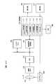
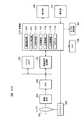
- FIG. 2shows the main configuration of a camera according to an embodiment of the present invention.
- the camera 100is provided, for example, in a portable terminal device such as a portable telephone, a personal handy-phone system (PHS), a personal digital assistant (PDA), a portable game machine or the like.
- a portable terminal devicesuch as a portable telephone, a personal handy-phone system (PHS), a personal digital assistant (PDA), a portable game machine or the like.
- PHSpersonal handy-phone system
- PDApersonal digital assistant
- the camera 100has an AF function and an automatic scene determination function.
- the camera 100is also configured to perform AF using a passive method.
- the camera 100includes a lens 101, an imaging device 102, an ADC (Analogue Digital Converter) 103, an image signal processing unit 104, a buffer memory 105, a control unit 110, a display unit 106, an operation unit 107, and an LED 108. And an AF driver 109.
- ADCAnalogue Digital Converter
- the lens 101condenses imaging light on an imaging device 102 such as a CCD.
- the lens 101is moved by the AF driver 109 in the direction of the optical axis of the lens 101 indicated by a dashed dotted line in the drawing. Thereby, the focus of the imaging light is adjusted to the imaging surface of the imaging element 102.
- the AF driver 109is composed of a device such as a piezo, voice coil, stepping motor, etc., and according to an instruction from the control unit 110, as shown in FIG. 1A, the lens 101 has an infinite mechanical end point and a macro mechanical end point.
- the imaging lightis brought into focus on the imaging surface of the imaging element 102 by moving between (at the time of AF control and between the infinity side optical end point and the macro side optical end point).
- the image signal output from the imaging element 102is input to the image signal processing unit 104 and the buffer memory 105 via the ADC 103.
- the image signal processing unit 104performs image processing such as white balance control on the output signal of the ADC 103 or the image signal stored in the buffer memory 105, and outputs a signal after image processing to the control unit 110.
- the control unit 110is configured by a microcomputer or the like, and controls the entire camera 100 and performs position control of the lens 101. Further, the control unit 110 is connected to the display unit 106 including an LCD or the like and the operation unit 107.
- the control unit 110includes a scene determination unit 111, a person determination unit 112, an AE (Auto Exposure) control unit 113, an AF control unit 114, an LED control unit 115, and a counter 116.
- AEAuto Exposure
- the person determination unit 112determines the presence or absence of a person.
- the AE control unit 113detects subject brightness information, and performs AE control according to the subject brightness.
- the person determination and the AE controlare known techniques, so detailed description will be omitted.
- the AF control unit 114realizes AF control by transmitting a control signal to the AF driver 109. Specifically, the AF control unit 114 moves the lens 101 using the AF driver 109 so that the contrast of the image signal from the image signal processing unit 104 is maximized. Further, the AF control unit 114 estimates the position (focus position) of the lens 101 based on the control amount (which may be restated as a control result). It is possible to obtain subject distance information indicating the distance to the subject based on the estimated position of the lens 101.
- the lens 101is accurately moved by the AF driver 109 by an amount according to the control amount from the AF control unit 114, the actual position of the lens 101 matches the position of the lens 101 estimated. It should. However, if an error occurs between the control amount from the AF control unit 114 and the actual movement amount due to an error such as the movement accuracy of the lens 101, the position of the lens 101 estimated based on the control amount Is shifted from the actual position of the lens 101. In this embodiment, since the AF control using the continuous AF method is performed, as shown in FIG. 1B, the position of the lens 101 estimated based on the control amount as the number of AF operations increases, An error with the actual position of the lens 101 is accumulated, and the error becomes large.
- the estimation of the lens position based on the control amount in the AF control unit 114is not limited to the case performed by the AF control unit 114, and may be performed by, for example, the scene determination unit 111.
- the LED control unit 115forms LED flash control information based on the subject brightness information from the AE control unit 113, and controls the LED 108 based on the LED flash control information.
- the scene determination unit 111includes the person information obtained from the person determination unit 112, the subject brightness information obtained from the AE control unit 113, the subject distance information obtained from the AF control unit 114 or the like, and the LED control unit 115. Based on the obtained LED flash control information, it is determined which of the “person scene mode”, the “macro scene mode”, and the “landscape scene mode” the current shooting scene is.
- the scene determination unit 111outputs scene information, which is the determination result, to the display unit 106 together with the image information, and causes the display unit 106 to display them.
- the counter 116counts the number of times of AF operation, which is the number of times of performing the AF control, the number of captured image frames, or the time since the start of the continuous AF operation.
- the counter 116notifies the AF driver 109 of this when the number of AF operations, the number of captured image frames, or the time exceeds a predetermined threshold. Then, upon receiving this notification, the AF driver 109 moves the position of the lens 101 to the reference position. Thereby, the position of the lens 101 is reset to the reference position.
- This reference positionis the mechanical end point shown in FIG.
- the reference positionmay be the optical end point shown in FIG.
- the counter 116estimates the position of the lens 101 when the number of AF operations, the number of captured image frames, or the time exceeds a predetermined threshold (the AF control unit 114 of the present embodiment). Notify on). Then, after the circuit that estimates the position of the lens 101 once resets the estimated position of the lens 101, it estimates the position of the lens 101 by sequentially using the new control amount output from the AF control unit 114 again. .
- the lens estimationis performed while resetting the position of the lens 101 to the reference position. Since the position is reset and then the new control amount output from the AF control unit 114 is sequentially used to estimate the position of the lens 101, the accumulated error of the lens estimation position can be reduced. As a result, since the estimation accuracy of the lens position is improved, the accuracy of the automatic scene determination is improved.
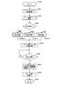
- FIG. 3mainly shows an operation of moving the lens 101 to the reference position when a predetermined condition is satisfied during the continuous AF operation, which is a feature of the present embodiment.
- step ST10When the process is started in step ST10 (ie, when the camera 100 is activated), the camera 100 starts the continuous AF operation in the subsequent step ST11.
- step ST11automatic scene determination and object position estimation (lens position estimation) operations are started.
- step ST12the counter 116 starts counting the number of captured image frames.
- step ST13it is determined whether the number of captured image frames counted by the counter 116 is equal to or more than a predetermined value.
- the processmoves to step ST14, and the AF driver 109 moves the lens 101 to the reference position.
- the movement operation to this reference positionmay be the same as the operation performed at the time of general one-shot AF operation, or the AF may be operated by the maximum amount that the lens can be physically driven.
- the camera 100resets the lens estimation position calculated up to that point. Thereby, the accumulated error of the lens estimated position is cleared.
- step ST15the number of captured image frames in the counter 116 is initialized (reset), and in the subsequent step ST16, the process ends.
- the camera 100resets the position of the lens 101 and the estimated position of the lens 101 when the number of captured image frames after the start of the continuous AF operation becomes equal to or more than a predetermined value.
- FIG. 4shows an image of the error of the lens estimated position.
- the example of FIG. 4shows an example in which the position of the lens 101 is moved to the reference position when the number of captured image frames after the continuous AF operation exceeds 100. From the figure, as the number of captured image frames after the continuous AF operation increases, the error which is the difference between the estimated position and the actual position increases, but the accumulated error is increased by returning the lens 101 to the reference position. It is understood that it is cleared to 0.
- the camera 100When the camera 100 starts the continuous AF operation again, it sequentially moves the lens 101 from the reference position to perform the continuous AF operation, and accordingly, the reference position based on the control amount of the AF control unit 114.
- the estimated position of the lens 101is sequentially calculated.
- the captured image frames after the start of the continuous AF operationare counted, and the position of the lens 101 and the estimated position of the lens 101 when the counted number of captured image frames becomes a predetermined value or more.
- the estimated position of the lens 101may be reset.
- the position of the lens 101is set to the reference position.
- the accumulated error of the lens estimated position estimated based on the control amount of the AF control unit 114is reset, so that the lens position estimation accuracy can be improved.
- the accuracy of automatic scene determinationcan be improved.
- the present embodimenthas described the case where the number of AF operations, the number of captured image frames, or the time after the start of the continuous AF operation exceeds the threshold, the present invention is not limited thereto.
- the position of the lens 101may be reset to the reference position when the number of AF operations, the number of captured image frames, or the time from the time when estimation of the separation position is started becomes equal to or more than a threshold.
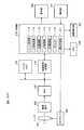
- FIG. 5shows the main configuration of the camera 200 of the present embodiment.
- the camera 200 according to the present embodimenthas a counter 116 based on the posture detection unit 201 that detects the posture of the camera 200 and the posture information obtained by the posture detection unit 201 in addition to the configuration of the camera 100 (FIG. 1). And a correction calculation unit 211 that corrects the count value of
- the camera 200 of the present embodimentcorrects the number of AF operations, the number of captured image frames, or the count value of time based on the posture information.
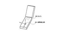
- the posture detection unit 201may also be mounted on the mobile telephone.
- the posture detection unit 201is, for example, an acceleration sensor, detects a gravity difference that changes according to a change in the posture of the camera 200 (mobile phone), and detects the posture of the camera 200 based on the gravity difference.
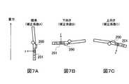
- the posture detection unit 201detects a plurality of postures such as a standard posture (FIG. 7A), a downward posture (FIG. 7B) or an upward posture (FIG. 7C). Then, the correction calculation unit 211 corrects the count value using a correction coefficient set in advance for each posture.
- a standard postureFIG. 7A
- a downward postureFIG. 7B
- an upward postureFIG. 7C
- the correction coefficient in the standard postureis set to 1.0
- the correction coefficient in the downward postureis set to 1.05
- the correction coefficient in the upward postureis set to 1.10.
- the corrected count value when the count value of the counter 116 is 10is 10 in the standard posture, 10.5 in the downward posture, and 11 in the upward posture.
- the lens 101is reset to the reference position earlier as the posture is more affected. Can be controlled.
- step ST20When the process is started in step ST20 (ie, when the camera 200 is activated), the camera 200 starts the continuous AF operation in the subsequent step ST21. In the subsequent step ST22, the counter 116 starts counting the number of captured image frames.
- step ST23the attitude of the camera 200 (mobile phone) is detected by the attitude detection unit 201. Then, if the detected posture is the standard posture, the correction calculation unit 211 reads the correction coefficient A in step ST24-1, and the number of captured image frames counted by the counter 116 in step ST25 is the correction coefficient A. Use to correct. If the detected posture is the downward posture, the correction calculation unit 211 reads the correction coefficient B in step ST24-2, and the number of captured image frames counted by the counter 116 in step ST25 is the correction coefficient B. Use to correct. If the detected posture is the upward posture, the correction calculation unit 211 reads the correction coefficient C in step ST24-3, and the number of captured image frames counted by the counter 116 in step ST25 is the correction coefficient C. Use to correct.
- steps ST23-ST24-ST25may be performed while switching the correction coefficient as needed when the posture change is detected during counting of the number of captured image frames.
- step ST26it is determined whether the number of captured image frames after correction is a predetermined number or more. Then, when the number of captured image frames becomes a predetermined number or more, the process moves to step ST27, and the AF driver 109 moves the lens 101 to the reference position. In addition, the camera 200 resets the lens estimation position calculated up to that time. Thereby, the accumulated error of the lens estimated position is cleared.
- step ST28the number of captured image frames in the counter 116 is initialized (reset), and in the subsequent step ST29, the process ends.
- the camera 200corrects the count value of the number of captured image frames after the start of the continuous AF operation according to the posture, and when the count value after the correction becomes a predetermined value or more, the lens 101 And the estimated position of the lens 101.
- the count value of the captured image frame after the start of the continuous AF operationis corrected according to the posture, but of course, instead of the number of captured image frames, the continuous AF is performed.
- the number of AF operations or time after the start of the operationmay be corrected according to the posture.
- the number of AF operations, the number of captured image frames, or the time after the start of the continuous AF operationdepends on the posture of the camera 200. Since the correction is performed, in addition to the effects of the first embodiment, the lens 101 can be reset to the reference position as soon as the posture in which the lens estimation position is likely to cause an error can be suppressed.
- FIG. 9shows the main configuration of the camera 300 according to the present embodiment.
- the camera 300 of the present embodimentincludes a camera shake detection unit 301 and a motion detection unit 311.
- the camera shake detection unit 301is formed of, for example, an acceleration sensor, and detects camera shake of the mobile terminal device in which the camera 300 is mounted.
- the motion detection unit 311detects subject shake based on the captured image.
- the movement of the lens 101 to the reference positionis awaited until the object shake due to the camera 311 is detected, and the lens 101 is moved to the reference position using camera shake or object shake as a trigger.
- the captured imagebecomes unsightly due to the movement of the lens 101 to the reference position. That is, when the lens 101 is immediately moved to the reference position when the number of AF operations, the number of captured image frames, or the time reaches a certain value or more, the AF operation can be seen in the captured image every predetermined period. May be unsightly.
- the lens 101when the captured image is blurred, the lens 101 is moved to the reference position by taking advantage of the fact that the AF operation hardly appears in the captured image. As a result, it is possible to prevent the unsightliness of the captured image when moving the lens 101 to the reference position.
- step ST30When the process is started in step ST30 (ie, when the camera 300 is activated), the camera 300 starts the continuous AF operation in the subsequent step ST31.
- the counter 116starts counting the number of captured image frames.
- step ST33it is determined whether the number of captured image frames counted by the counter 116 is equal to or greater than a predetermined value. When the number of captured image frames becomes equal to or more than a predetermined value, the process proceeds to step ST34.
- step ST34the process waits until camera shake detected by the camera shake detection unit 301 or camera shake detected by the motion detection unit 311. If camera shake or camera shake is detected, the process proceeds to step ST35.
- step ST35the AF driver 109 moves the lens 101 to the reference position. Also, in response to this, the camera 300 resets the lens estimated position calculated so far. Thereby, the accumulated error of the lens estimated position is cleared.
- step ST36the number of captured image frames in the counter 116 is initialized (reset), and in the subsequent step ST37, the process ends.
- the camera 300waits for the movement of the lens 101 to the reference position until camera shake or subject shake is detected, and when camera shake or subject shake is detected, the position of the lens 101 and the lens 101 are estimated. Reset the position.
- the movement of the lens 101 to the reference positionis on standby until camera shake or subject shake is detected, and camera shake or subject shake is detected.
- the unsightliness of the captured image caused by moving the lens 101 to the reference positionis prevented by resetting the position of the lens 101 and the estimated position of the lens 101 when being corrected. Can.
- the case where the camera shake detection unit 301 and the motion detection unit 311 are providedhas been described. However, only one of the camera shake detection unit 301 or the motion detection unit 311 is provided, and either camera shake or subject blurring is provided.
- the lens 101may be moved to the reference position using only one as a trigger.
- the camera, the portable terminal device, and the lens position control method according to the present inventionare useful for a camera such as a camera-equipped mobile phone. Moreover, it is also possible to incorporate in various electronic devices other than a portable terminal as a position control method of a lens.
Landscapes
- Physics & Mathematics (AREA)
- Engineering & Computer Science (AREA)
- Multimedia (AREA)
- Signal Processing (AREA)
- General Physics & Mathematics (AREA)
- Optics & Photonics (AREA)
- Studio Devices (AREA)
- Lens Barrels (AREA)
- Automatic Focus Adjustment (AREA)
Abstract
Description
Translated fromJapanese本発明は、カメラ付き携帯電話機などのカメラ、携帯端末装置及びレンズの位置制御方法に関する。The present invention relates to a camera such as a camera-equipped mobile phone, a mobile terminal device, and a lens position control method.
携帯電話には多彩なマルチメディア機能が搭載されるようになり、通話のみに留まらず静止画撮影、動画撮影等を行ったり、TV電話として用いられるカメラ付き携帯電話機が知られている。携帯電話機に搭載されるカメラに搭載されるオートフォーカス(以下、AFという)には、カメラ自体の小型化に伴い、小型化及び低コストが求められる。Mobile phones have come to be equipped with a variety of multimedia functions, and camera-equipped mobile phones that are used as video phones are also known as still pictures and moving pictures, etc., as well as only in calls. As auto-focus (hereinafter referred to as AF) mounted on a camera mounted on a mobile phone is required to be downsized and cost-reduced as the camera itself is downsized.
一般的にAFの方式は、大きく、アクティブ方式とパッシブ方式とに分けられる。アクティブ方式は、被写体に赤外線・超音波などを照射し、その反射波が戻るまでの時間や照射角度により距離を検出する方式である。パッシブ方式は、画像からフォーカス状態を評価してレンズを移動させる方式であり、主に、被写体におけるコントラスト状態(鮮鋭度)を示す成分を評価値(AF評価値)として用いて、コントラストが最大になるようにレンズ位置を制御する。Generally, AF methods are roughly divided into active methods and passive methods. The active method is a method in which an object is irradiated with infrared rays, ultrasonic waves or the like, and the distance is detected based on the time until the reflected wave returns and the irradiation angle. The passive method is a method in which the lens is moved by evaluating the focus state from the image, and mainly the component indicating the contrast state (sharpness) of the object is used as the evaluation value (AF evaluation value) to maximize the contrast. Control the lens position to be
ここで、アクティブ方式においては、一般に構成が複雑になるため、カメラ付き携帯電話機に搭載されるカメラには、構成が簡易な構成のパッシブ方式が用いられることが殆どである。Here, in the active method, since the configuration is generally complicated, in most cases, a passive method having a simple configuration is used for a camera mounted on a mobile phone with a camera.
ところで、この種のカメラでは、レンズの位置を移動させることにより、AFを実現している。従って、レンズを正確に位置決めすることが、AFの性能を向上させる点で重要である。従来、レンズの位置ずれを補正する技術として、例えば特許文献1に記載されたものがある。特許文献1では、レンズを移動させた後に、画像情報を確認し、合焦が不完全であればレンズを再度移動させる技術が開示されている。By the way, in this type of camera, AF is realized by moving the position of the lens. Therefore, accurate lens positioning is important in improving AF performance. Conventionally, as a technique for correcting the positional deviation of a lens, for example, there is one described in
また、近年、自動シーン判定機能を搭載したカメラが提案されている。自動シーン判定機能とは、被写体にレンズを向けるだけで、「人物シーンモード」、「マクロシーンモード」、「風景シーンモード」等のシーンモードの中から、カメラが最適なシーンモード選択して、シーンモードを自動で設定する機能である。これにより、ユーザが撮影環境に合わせて細かくシーンモードを設定する必要がなくなるので、撮影が簡単になる。Also, in recent years, cameras equipped with an automatic scene determination function have been proposed. With the automatic scene judgment function, just by pointing the lens to the subject, the camera can select the optimal scene mode from the scene modes such as “person scene mode”, “macro scene mode”, “landscape scene mode”, etc. It is a function to set the scene mode automatically. This eliminates the need for the user to set the scene mode in detail according to the shooting environment, thus simplifying shooting.
ここで、自動シーン判定機能を実現するためには、一般に、被写体の距離情報が使われ、この距離情報は、レンズ位置(フォーカス位置)に基づいて求めることができる。Here, in order to realize the automatic scene determination function, generally, distance information of the subject is used, and this distance information can be obtained based on the lens position (focus position).
しかしながら、カメラ付き携帯電話機のカメラのように小型化が求められるカメラの場合には、小型化を実現するために、レンズ位置を直接検出する検出部(例えばホール素子等)は搭載することができない場合がある。However, in the case of a camera that is required to be miniaturized, such as a camera of a mobile phone with a camera, a detection unit (for example, a Hall element or the like) that directly detects the lens position can not be mounted to achieve miniaturization. There is a case.
この場合、AF制御によりどれだけレンズを移動させたかを示す情報(制御量、制御結果)に基づいて、レンズの位置(フォーカス位置)を推測し、この推測結果に基づいて被写体の距離情報を求める必要がある。In this case, the position (focus position) of the lens is estimated based on information (control amount, control result) indicating how much the lens is moved by AF control, and distance information of the subject is determined based on the estimation result. There is a need.
しかしながら、上述したようにレンズ位置を推測した場合、推測誤差が蓄積し、その結果、自動シーン判定の精度が低下するという課題がある。However, when the lens position is estimated as described above, an estimation error is accumulated, and as a result, there is a problem that the accuracy of the automatic scene determination is lowered.
図1を用いて、レンズ推測位置の誤差について簡単に説明する。図1Aにおいて、レンズ10は、無限(∞)側機械的端点とマクロ側機械的端点との間で移動可能とされている。なお、この無限(∞)側機械的端点とマクロ側機械的端点とは別に、レンズ10の調整ポイントである無限(∞)側光学端点とマクロ側光学端点が設定されている。これら光学端点は、機械的端点のような物理的な端ではなく、AFのピント位置を元にあらかじめ設定されるAFの無限側端点及びマクロ側端点である。The error of the lens estimation position will be briefly described using FIG. In FIG. 1A, the
上述したように、レンズ10は、無限側機械的端点とマクロ側機械的端点との間で移動可能とされているが、無限側機械的端点の近傍、及び、マクロ側機械的端点の近傍では、ピントが合わないデフォーカスになることが多い。そのため、AF制御時には、ピントが合う範囲である、無限側光学端点とマクロ側光学端点との間で、レンズ10を移動させることが一般に行われる。As described above, the
図1Aに示すように、実際のレンズ位置と、AF制御部での制御量(制御情報又は制御結果と言い換えてもよい)に基づいて推測されるレンズ推測位置との間に、誤差が生じる可能性がある。特に、連続的にAF動作を行うことで、フォーカス位置を随時合わせる場合(以下、コンティニュアスAFとする)、AF動作回数が増加すると誤差が蓄積するので、図1Bに示すように、実際のレンズ位置と、AF制御部での制御量に基づいて推測されるレンズ推測位置との間の誤差は増大し、この結果、レンズ位置の推測精度が低下するという問題があった。As shown in FIG. 1A, an error may occur between the actual lens position and the lens estimated position estimated based on the control amount in the AF control unit (which may be reworded as control information or control result) There is sex. In particular, when the focus position is adjusted as needed (hereinafter referred to as continuous AF) by continuously performing the AF operation, an error is accumulated as the number of AF operations increases, so as shown in FIG. 1B, as shown in FIG. An error between the lens position and the lens estimated position estimated based on the control amount in the AF control unit is increased, and as a result, there is a problem that the estimation accuracy of the lens position is reduced.
本発明の目的は、AF制御での制御結果に基づいてレンズ位置を推測する場合において、レンズ位置の推測精度を向上し、自動シーン判定の精度を向上したカメラ、携帯端末装置及びレンズの位置制御方法を提供することである。SUMMARY OF THE INVENTION An object of the present invention is to improve the accuracy of lens position estimation and to improve the accuracy of automatic scene determination, in the case of estimating the lens position based on the control result in AF control, and the position control of the camera, portable terminal and lens It is to provide a method.
本発明のカメラの一つの態様は、オートフォーカス制御部と、前記オートフォーカス制御部の制御結果に基づいて、レンズの位置を推測するレンズ位置推測部と、オートフォーカス回数、時間又は撮影フレーム数が閾値以上となった場合、前記レンズの位置を基準位置に移動するレンズ駆動部と、を具備する構成を採る。According to one aspect of the camera of the present invention, an autofocus control unit, and a lens position estimation unit that estimates the position of the lens based on the control result of the autofocus control unit; And a lens drive unit configured to move the position of the lens to a reference position when the threshold value is exceeded.
本発明によれば、カメラ及びカメラ付携帯端末装置のシーン判定におけるシーン判定精度を向上させることができる。According to the present invention, it is possible to improve the scene determination accuracy in the scene determination of the camera and the camera-equipped mobile terminal device.
以下、本発明の実施の形態について、図面を参照して詳細に説明する。Hereinafter, embodiments of the present invention will be described in detail with reference to the drawings.
[実施の形態1]
図2に、本発明の一実施の形態に係るカメラの要部構成を示す。カメラ100は、例えば、携帯電話機、PHS(Personal Handy-Phone System)、PDA(Personal Digital Assistants:携帯情報端末)、携帯ゲーム機等の携帯端末装置に設けられる。First Embodiment
FIG. 2 shows the main configuration of a camera according to an embodiment of the present invention. The
カメラ100は、AF機能と、自動シーン判定機能とを有する。また、カメラ100は、パッシブ方式を用いて、AFを行うようになっている。The
カメラ100は、レンズ101と、撮像素子102と、ADC(Analogue Digital Converter)103と、画像信号処理部104と、バッファメモリ105と、制御部110と、表示部106と、操作部107と、LED108と、AFドライバ109とを有する。The
レンズ101は、撮像光をCCDなどの撮像素子102に集光する。ここで、レンズ101は、AFドライバ109によって、図中の一点鎖線で示すレンズ101の光軸方向に移動される。これにより、撮像光の焦点が撮像素子102の撮像面に合わせられる。The
AFドライバ109は、ピエゾ、ボイスコイル、ステッピングモータなどのデバイスからなり、制御部110からの指示によって、図1Aに示したように、レンズ101を無限側機械的端点とマクロ側機械的端点との間(AF制御時には無限側光学端点とマクロ側光学端点との間)で移動させることにより、撮像光を撮像素子102の撮像面に合焦させる。The
撮像素子102から出力された画像信号は、ADC103を介して画像信号処理部104及びバッファメモリ105に入力される。The image signal output from the
画像信号処理部104は、ADC103の出力信号又はバッファメモリ105に蓄積された画像信号に対してホワイトバランス制御などの画像処理を施し、画像処理後の信号を制御部110に出力する。The image
制御部110は、マイクロコンピュータ等から構成され、カメラ100全体の制御を行うとともに、レンズ101の位置制御を行う。また、制御部110は、LCD等からなる表示部106及び操作部107に接続されている。The control unit 110 is configured by a microcomputer or the like, and controls the
制御部110は、シーン判定部111と、人物判定部112と、AE(Auto Exposure)制御部113と、AF制御部114と、LED制御部115と、カウンタ116とを有する。The control unit 110 includes a
人物判定部112は、人物の有無等を判定する。AE制御部113は、被写体輝度情報を検出し、被写体輝度に応じてAE制御を行う。なお、人物判定及びAE制御は、既知の技術なので詳しい説明は省略する。The
AF制御部114は、AFドライバ109に制御信号を送出することで、AF制御を実現する。具体的には、AF制御部114は、画像信号処理部104からの画像信号のコントラストが最大となるように、AFドライバ109を使ってレンズ101を移動させる。また、AF制御部114は、制御量(制御結果と言い換えてもよい)に基づいてレンズ101の位置(フォーカス位置)を推測する。なお、この推測されるレンズ101の位置に基づき、被写体までの距離を示す被写体距離情報を得ることができる。The
ここで、レンズ101が、AF制御部114からの制御量に応じた量だけ、AFドライバ109によって正確に移動されれば、実際のレンズ101の位置と、推測されたレンズ101との位置は一致するはずである。しかし、レンズ101の移動精度等の誤差が原因となって、AF制御部114からの制御量と実際の移動量との間に誤差が生じると、制御量に基づいて推測されるレンズ101の位置は、実際のレンズ101の位置とずれてしまう。本実施の形態では、コンティニュアスAF方式を用いたAF制御を行うので、図1Bに示したように、AF動作回数が増加するに従って、制御量に基づいて推測されるレンズ101の位置と、実際のレンズ101の位置との誤差が蓄積されて、誤差が大きくなる。Here, if the
なお、AF制御部114での制御量に基づくレンズ位置の推測は、AF制御部114で行う場合に限らず、例えばシーン判定部111で行ってもよい。The estimation of the lens position based on the control amount in the
LED制御部115は、AE制御部113からの被写体輝度情報に基づいてLEDフラッシュ制御情報を形成し、このLEDフラッシュ制御情報によってLED108を制御する。The
シーン判定部111は、人物判定部112より得られた人物情報と、AE制御部113より得られた被写体輝度情報と、AF制御部114等より得られた被写体距離情報と、LED制御部115により得られたLEDフラッシュ制御情報と、に基づいて、現在の撮影シーンが、例えば「人物シーンモード」、「マクロシーンモード」又は「風景シーンモード」のうちのどれであるかを判定する。シーン判定部111は、判定結果であるシーン情報を画像情報と共に表示部106に出力し、これらを表示させる。The
カウンタ116は、コンティニュアスAF動作を開始してからの、AF制御を行った回数であるAF動作回数、撮像画像フレーム数、または時間をカウントする。The
カウンタ116は、AF動作回数、撮像画像フレーム数、または時間が所定の閾値以上になった場合に、このことをAFドライバ109に通知する。そして、AFドライバ109は、この通知を受けると、レンズ101の位置を基準位置に移動させる。これにより、レンズ101の位置が基準位置にリセットされる。The
この基準位置とは、図1に示した機械的端点である。また基準位置は、図1に示した光学端点であってもよい。但し、基準位置は、物理的な基準となる位置なので、機械的接点を基準位置にすることが好ましい。This reference position is the mechanical end point shown in FIG. The reference position may be the optical end point shown in FIG. However, since the reference position is a physical reference position, it is preferable to set the mechanical contact to the reference position.
また、カウンタ116は、上記AF動作回数、撮像画像フレーム数、または時間が所定の閾値以上になった場合に、このことをレンズ101の位置を推測する回路(本実施の形態のAF制御部114)に通知する。すると、レンズ101の位置を推測する回路は、一旦、レンズ101の推測位置をリセットした後に、再びAF制御部114から出力される新たな制御量を順次用いてレンズ101の位置を推測していく。In addition, the
このように、コンティニュアスAF動作開始後の、AF動作回数、撮像画像フレーム数、または時間が所定の閾値以上になった場合に、レンズ101の位置を基準位置にリセットすると共に算出したレンズ推測位置をリセットし、その後に、新たにAF制御部114から出力される新たな制御量を順次用いてレンズ101の位置を推測したことにより、レンズ推測位置の累積誤差を低減できる。この結果、レンズ位置の推測精度が向上するので、自動シーン判定の精度が向上する。As described above, when the number of AF operations, the number of captured image frames, or the time after the start of the continuous AF operation becomes equal to or more than a predetermined threshold, the lens estimation is performed while resetting the position of the
次に、図3を用いて、本実施の形態の動作を説明する。なお、図3は、本実施の形態の特徴である、コンティニュアスAF動作中、所定の条件になったときに、レンズ101を基準位置に移動させる動作を中心に示したものである。Next, the operation of this embodiment will be described using FIG. FIG. 3 mainly shows an operation of moving the
カメラ100は、ステップST10で処理を開始すると(すなわちカメラ100が起動されると)、続くステップST11でコンティニュアスAF動作を開始する。このコンティニュアスAF動作の開始に伴って、自動シーン判定及び被写体位置推測(レンズ位置推測)動作が開始される。When the process is started in step ST10 (ie, when the
続くステップST12では、カウンタ116によって撮像画像フレーム数のカウントが開始される。ステップST13では、カウンタ116によってカウントされた撮像画像フレーム数が一定以上か否か判断する。In the subsequent step ST12, the
そして、撮像画像フレーム数が一定以上となると、ステップST14に移って、AFドライバ109がレンズ101を基準位置に移動させる。この基準位置への移動動作は、一般的なワンショットAF動作時に行われる動作と同様でもいいし、レンズが物理的に駆動できる最大量分AFを動作させることでもよい。また、カメラ100は、これに伴って、それまで計算されたレンズ推測位置をリセットする。これにより、レンズ推測位置の累積誤差がクリアされる。Then, when the number of captured image frames becomes a predetermined number or more, the process moves to step ST14, and the
次に、ステップST15において、カウンタ116の撮像画像フレーム数が初期化(リセット)され、続くステップST16で処理を終了する。このように、カメラ100は、コンティニュアスAF動作開始後の撮像画像フレーム数が一定値以上となった場合に、レンズ101の位置及びレンズ101の推測位置をリセットする。Next, in step ST15, the number of captured image frames in the
図4に、レンズ推測位置の誤差のイメージを示す。図4の例は、コンティニュアスAF動作後の撮像画像フレーム数が100を超えた場合に、レンズ101の位置を基準位置に移動させた例を示すものである。図から、コンティニュアスAF動作後の撮像画像フレーム数が増えるに従って、推測位置と実際の位置との差である誤差が増加していくが、レンズ101を基準位置に戻すことにより、累積誤差が0にクリアされることが分かる。FIG. 4 shows an image of the error of the lens estimated position. The example of FIG. 4 shows an example in which the position of the
カメラ100は、再びコンティニュアスAF動作を開始すると、基準位置からレンズ101を順次移動させてコンティニュアスAF動作を行うと共に、これに伴って、AF制御部114の制御量に基づいて基準位置からのレンズ101の推測位置を順次算出する。When the
なお、図3の例では、コンティニュアスAF動作を開始後の撮像画像フレームをカウントし、カウントした撮像画像フレーム数が一定値以上となった場合に、レンズ101の位置及びレンズ101の推測位置をリセットした例について説明したが、上述したように、撮像画像フレーム数に換えて、コンティニュアス動作開始後の、AF動作回数または時間が一定値以上となった場合に、レンズ101の位置及びレンズ101の推測位置をリセットしてもよい。In the example of FIG. 3, the captured image frames after the start of the continuous AF operation are counted, and the position of the
以上説明したように、本実施の形態によれば、コンティニュアスAF動作開始後の、AF動作回数、撮像画像フレーム数、または時間が閾値以上になった場合に、レンズ101の位置を基準位置にリセットしたことにより、AF制御部114の制御量に基づいて推測されるレンズ推測位置の累積誤差がリセットされるので、レンズ位置の推測精度を向上させることができる。この結果、自動シーン判定の精度を向上させることができる。As described above, according to the present embodiment, when the number of AF operations, the number of captured image frames, or the time after the start of the continuous AF operation exceeds the threshold, the position of the
なお、本実施の形態では、コンティニュアスAF動作開始後の、AF動作回数、撮像画像フレーム数、または時間が閾値以上になった場合について説明したが、これに限らず、たとえば、基準点から離れ位置の推測を開始した時点からの、AF動作回数、撮像画像フレーム数、または時間が閾値以上になった場合にレンズ101の位置を基準位置にリセットしてもよい。Although the present embodiment has described the case where the number of AF operations, the number of captured image frames, or the time after the start of the continuous AF operation exceeds the threshold, the present invention is not limited thereto. For example, from the reference point The position of the
[実施の形態2]
図2との対応部分に同一符号を付して示す図5に、本実施の形態のカメラ200の要部構成を示す。本実施の形態のカメラ200は、カメラ100(図1)の構成に加えて、カメラ200の姿勢を検出する姿勢検出部201と、姿勢検出部201により得られた姿勢情報に基づいて、カウンタ116のカウント値を補正する補正計算部211とを有する。Second Embodiment
FIG. 5, in which parts corresponding to those in FIG. 2 are assigned the same reference numerals, shows the main configuration of the
本実施の形態のカメラ200は、AF動作回数、撮像画像フレーム数、または時間のカウント値を、姿勢情報を基に補正する。The
図6に示すように、カメラ200を携帯電話機に搭載する場合には、姿勢検出部201も携帯電話機に搭載すればよい。姿勢検出部201は、例えば加速度センサであり、カメラ200(携帯電話機)の姿勢の変化に応じて変化する重力差を検出し、この重力差に基づいてカメラ200の姿勢を検出する。As shown in FIG. 6, when the
姿勢検出部201は、例えば図7に示すように、標準姿勢(図7A)か下向き姿勢(図7B)か上向き姿勢(図7C)かなどの複数の姿勢を検出する。そして、補正計算部211が、予め各姿勢毎に設定された補正係数を使ってカウント値を補正する。For example, as shown in FIG. 7, the
例えば、標準姿勢での補正係数を1.0、下向き姿勢での補正係数を1.05、上向き姿勢での補正係数を1.10に設定しておく。この場合、カウンタ116のカウント値が10のときの補正後のカウント値は、標準姿勢の場合に10、下向き姿勢の場合に10.5、上向き姿勢の場合に11となる。For example, the correction coefficient in the standard posture is set to 1.0, the correction coefficient in the downward posture is set to 1.05, and the correction coefficient in the upward posture is set to 1.10. In this case, the corrected count value when the count value of the
重力による影響が多い姿勢(すなわち推測位置に誤差が生じ易い姿勢)ほど、予め補正係数を高めに設定することで、影響の多い姿勢の場合ほど早めにレンズ101を基準位置にリセットして累積誤差の増加を抑制できるようになる。By setting the correction coefficient higher in advance as the posture is more affected by gravity (that is, the posture in which an error is likely to occur in the estimated position), the
次に、図8を用いて、本実施の形態の動作を説明する。Next, the operation of this embodiment will be described using FIG.
カメラ200は、ステップST20で処理を開始すると(すなわちカメラ200が起動されると)、続くステップST21でコンティニュアスAF動作を開始する。続くステップST22では、カウンタ116によって撮像画像フレーム数のカウントが開始される。When the process is started in step ST20 (ie, when the
ステップST23では、姿勢検出部201によってカメラ200(携帯電話機)の姿勢が検出される。そして、検出された姿勢が標準姿勢であった場合には、補正計算部211が、ステップST24-1において補正係数Aを読み出し、ステップST25においてカウンタ116によってカウントされた撮像画像フレーム数を補正係数Aを用いて補正する。また、検出された姿勢が下向き姿勢であった場合には、補正計算部211が、ステップST24-2において補正係数Bを読み出し、ステップST25においてカウンタ116によってカウントされた撮像画像フレーム数を補正係数Bを用いて補正する。また、検出された姿勢が上向き姿勢であった場合には、補正計算部211が、ステップST24-3において補正係数Cを読み出し、ステップST25においてカウンタ116によってカウントされた撮像画像フレーム数を補正係数Cを用いて補正する。In step ST23, the attitude of the camera 200 (mobile phone) is detected by the
なお、ステップST23-ST24-ST25の処理は、撮像画像フレーム数のカウント中に、姿勢変化を検出した際に、随時、補正係数を切替えながら行うとよい。The process of steps ST23-ST24-ST25 may be performed while switching the correction coefficient as needed when the posture change is detected during counting of the number of captured image frames.
ステップST26では、補正後の撮像画像フレーム数が一定以上か否か判断する。そして、撮像画像フレーム数が一定以上となると、ステップST27に移って、AFドライバ109がレンズ101を基準位置に移動させる。また、カメラ200は、これに伴って、それまで計算されたレンズ推測位置をリセットする。これにより、レンズ推測位置の累積誤差がクリアされる。In step ST26, it is determined whether the number of captured image frames after correction is a predetermined number or more. Then, when the number of captured image frames becomes a predetermined number or more, the process moves to step ST27, and the
次に、ステップST28において、カウンタ116の撮像画像フレーム数が初期化(リセット)され、続くステップST29で処理を終了する。このように、カメラ200は、コンティニュアスAF動作開始後の撮像画像フレーム数のカウント値を、姿勢に応じて補正し、この補正後のカウント値が一定値以上となった場合に、レンズ101の位置及びレンズ101の推測位置をリセットする。Next, in step ST28, the number of captured image frames in the
なお、図8の例では、コンティニュアスAF動作を開始後の撮像画像フレームのカウント値を姿勢に応じて補正した例について説明したが、勿論、撮像画像フレーム数に換えて、コンティニュアスAF動作開始後の、AF動作回数または時間を姿勢に応じて補正してもよい。In the example shown in FIG. 8, the count value of the captured image frame after the start of the continuous AF operation is corrected according to the posture, but of course, instead of the number of captured image frames, the continuous AF is performed. The number of AF operations or time after the start of the operation may be corrected according to the posture.
以上説明したように、本実施の形態によれば、実施の形態1に加えて、コンティニュアスAF動作開始後の、AF動作回数、撮像画像フレーム数、または時間を、カメラ200の姿勢に応じて補正したことにより、実施の形態1の効果に加えて、レンズ推測位置に誤差が生じ易い姿勢ほど早めにレンズ101を基準位置にリセットできるので、累積誤差の増加を一段と抑制できるようになる。As described above, according to the present embodiment, in addition to the first embodiment, the number of AF operations, the number of captured image frames, or the time after the start of the continuous AF operation depends on the posture of the
なお、本実施の形態では、姿勢に応じてカウント値を補正する場合について述べたが、姿勢に応じてステップST26での一定値(閾値)を変えるようにしても、同様の効果を得ることができる。Although the present embodiment has described the case where the count value is corrected according to the posture, the same effect can be obtained by changing the constant value (threshold) in step ST26 according to the posture. it can.
[実施の形態3]
図2との対応部分に同一符号を付して示す図9に、本実施の形態のカメラ300の要部構成を示す。本実施の形態のカメラ300は、カメラ100(図1)の構成に加えて、手ぶれ検出部301と、動き検出部311とを有する。手ぶれ検出部301は、例えば加速度センサによって構成されており、カメラ300が搭載された携帯端末装置の手ぶれを検出する。動き検出部311は、撮像画像に基づいて被写体ぶれを検出する。Third Embodiment
FIG. 9, in which parts corresponding to those in FIG. 2 are assigned the same reference numerals, shows the main configuration of the camera 300 according to the present embodiment. In addition to the configuration of the camera 100 (FIG. 1), the camera 300 of the present embodiment includes a camera
本実施の形態のカメラ300は、コンティニュアスAF動作開始後の、AF動作回数、撮像画像フレーム数、または時間が一定以上になった場合でも、手ぶれ検出部301による手ぶれ、または、動き検出部311による被写体ぶれが検出されるまでは、レンズ101の基準位置への移動を待機し、手ぶれまたは被写体ぶれをトリガとして、レンズ101を基準位置へ移動させる。In the camera 300 according to the present embodiment, the camera shake by the camera
これにより、レンズ101を基準位置へ移動させることが原因となって撮像画像が見苦しくなることを回避できる。つまり、AF動作回数、撮像画像フレーム数、または時間が一定以上になった時点で、すぐにレンズ101を基準位置へ移動させると、一定期間毎に撮像画像にAFの動作が見えて、撮像画像が見苦しくなるおそれがある。本実施の形態では、撮像画像にぶれがあったときに便乗して、レンズ101を基準位置へ移動させるので、撮像画像にAF動作が現れにくくなる。この結果、レンズ101を基準位置へ移動させる際の撮像画像の見苦しさを防ぐことができる。As a result, it is possible to avoid that the captured image becomes unsightly due to the movement of the
次に、図10を用いて、本実施の形態の動作を説明する。Next, the operation of the present embodiment will be described using FIG.
カメラ300は、ステップST30で処理を開始すると(すなわちカメラ300が起動されると)、続くステップST31でコンティニュアスAF動作を開始する。続くステップST32では、カウンタ116によって撮像画像フレーム数のカウントが開始される。ステップST33では、カウンタ116によってカウントされた撮像画像フレーム数が一定以上か否か判断する。撮像画像フレーム数が一定以上となると、ステップST34に移る。When the process is started in step ST30 (ie, when the camera 300 is activated), the camera 300 starts the continuous AF operation in the subsequent step ST31. In the subsequent step ST32, the
ステップST34では、手ぶれ検出部301による手ぶれ、または、動き検出部311による被写体ぶれが検出されるまで待機し、手ぶれまたは被写体ぶれが検出されると、ステップST35に移る。In step ST34, the process waits until camera shake detected by the camera
ステップST35では、AFドライバ109がレンズ101を基準位置に移動させる。また、カメラ300は、これに伴って、それまで計算されたレンズ推測位置をリセットする。これにより、レンズ推測位置の累積誤差がクリアされる。In step ST35, the
次に、ステップST36において、カウンタ116の撮像画像フレーム数が初期化(リセット)され、続くステップST37で処理を終了する。このように、カメラ300は、手ぶれまたは被写体ぶれが検出されるまで、レンズ101の基準位置への移動を待機し、手ぶれまたは被写体ぶれが検出されたときに、レンズ101の位置及びレンズ101の推測位置をリセットする。Next, in step ST36, the number of captured image frames in the
なお、図10の例では、コンティニュアスAF動作を開始後の撮像画像フレームをカウントする例について説明したが、勿論、コンティニュアスAF動作開始後の、AF動作回数または時間をカウントしてもよい。In the example shown in FIG. 10, an example of counting captured image frames after the start of the continuous AF operation has been described, but it goes without saying that the number of AF operations or time after the start of the continuous AF operation is counted. Good.
以上説明したように、本実施の形態によれば、実施の形態1に加えて、手ぶれまたは被写体ぶれが検出されるまで、レンズ101の基準位置への移動を待機し、手ぶれまたは被写体ぶれが検出されたときに、レンズ101の位置及びレンズ101の推測位置をリセットしたことにより、実施の形態1の効果に加えて、レンズ101を基準位置へ移動させることにより生じる撮像画像の見苦しさを防ぐことができる。As described above, according to the present embodiment, in addition to
なお、本実施の形態では、手ぶれ検出部301及び動き検出部311を設けた場合について述べたが、手ぶれ検出部301または動き検出部311のいずれか一方のみを設け、手ぶれまたは被写体ぶれのいずれか一方のみをトリガとしてレンズ101を基準位置へ移動させてもよい。In the present embodiment, the case where the camera
2009年5月11日出願の特願2009-114791の日本出願に含まれる明細書、図面および要約書の開示内容は、すべて本願に援用される。The disclosures of the specification, drawings and abstract included in the Japanese application of Japanese Patent Application No. 2009-114791 filed on May 11, 2009 are all incorporated herein by reference.
本発明に係るカメラ、携帯端末装置及びレンズの位置制御方法は、カメラ付き携帯電話機などのカメラに有用である。また、レンズの位置制御方法として携帯端末以外の各種電子機器に組み込むことも可能である。The camera, the portable terminal device, and the lens position control method according to the present invention are useful for a camera such as a camera-equipped mobile phone. Moreover, it is also possible to incorporate in various electronic devices other than a portable terminal as a position control method of a lens.
100、200、300 カメラ
101 レンズ
109 AFドライバ
110、210、310 制御部
111 シーン判定部
112 人物判定部
113 AE制御部
114 AF制御部
115 LED制御部
116 カウンタ
201 姿勢検出部
211 補正計算部
301 手ぶれ検出部
311 動き検出部
100, 200, 300
Claims (8)
Translated fromJapanese前記オートフォーカス制御部の制御結果に基づいて、レンズの位置を推測するレンズ位置推測部と、
オートフォーカス回数、時間又は撮影フレーム数が閾値以上となった場合、前記レンズの位置を基準位置に移動するレンズ駆動部と、
を具備するカメラ。An autofocus control unit,
A lens position estimation unit that estimates the position of the lens based on the control result of the autofocus control unit;
A lens driving unit that moves the position of the lens to a reference position when the number of times of autofocusing, the time, or the number of imaging frames is equal to or greater than a threshold value;
Equipped with a camera.
請求項1に記載のカメラ。The image processing apparatus further includes a correction unit that corrects the number of times of autofocusing, the time or the number of shooting frames, or the threshold according to the posture of the camera.
The camera according to claim 1.
請求項1に記載のカメラ。The lens driving unit moves the position of the lens to a reference position when the number of times of autofocusing, the time, or the number of shooting frames is equal to or greater than a threshold and camera shake or subject shake is detected.
The camera according to claim 1.
請求項1に記載のカメラ。The reference position for moving the lens is a mechanical end point,
The camera according to claim 1.
前記レンズ駆動部は、前記コンティニュアスオートフォーカス中に前記オートフォーカス回数、前記時間又は前記撮影フレーム数が閾値以上となった場合、前記レンズの位置を基準位置に移動する、
請求項1に記載のカメラ。The autofocus control unit performs continuous autofocus, which performs autofocus continuously.
The lens driving unit moves the position of the lens to a reference position when the number of times of autofocusing, the time, or the number of imaging frames becomes equal to or more than a threshold during the continuous autofocusing.
The camera according to claim 1.
前記レンズ位置推測部により得られたレンズ位置推定結果は、前記シーン判定部で用いられる、
請求項1に記載のカメラ。Further equipped with a scene determination unit,
The lens position estimation result obtained by the lens position estimation unit is used by the scene determination unit.
The camera according to claim 1.
オートフォーカス回数、時間又は撮影フレーム数が閾値以上となった場合、前記レンズの位置を基準位置に移動するレンズ駆動ステップと、
を含むレンズの位置制御方法。
A lens position estimation step of estimating a lens position based on a control result of the autofocus control unit;
A lens driving step of moving the position of the lens to a reference position when the number of times of autofocusing, the time, or the number of imaging frames is equal to or more than a threshold value;
Lens position control method including:
Priority Applications (2)
| Application Number | Priority Date | Filing Date | Title |
|---|---|---|---|
| EP10774693AEP2431780A1 (en) | 2009-05-11 | 2010-04-30 | Camera, portable terminal device, and lens position control method |
| US13/319,284US20120105709A1 (en) | 2009-05-11 | 2010-04-30 | Camera, portable terminal device, and lens position control method |
Applications Claiming Priority (2)
| Application Number | Priority Date | Filing Date | Title |
|---|---|---|---|
| JP2009114791AJP5524509B2 (en) | 2009-05-11 | 2009-05-11 | Camera, portable terminal device and lens position control method |
| JP2009-114791 | 2009-05-11 |
Publications (1)
| Publication Number | Publication Date |
|---|---|
| WO2010131433A1true WO2010131433A1 (en) | 2010-11-18 |
Family
ID=43084820
Family Applications (1)
| Application Number | Title | Priority Date | Filing Date |
|---|---|---|---|
| PCT/JP2010/003096WO2010131433A1 (en) | 2009-05-11 | 2010-04-30 | Camera, portable terminal device, and lens position control method |
Country Status (4)
| Country | Link |
|---|---|
| US (1) | US20120105709A1 (en) |
| EP (1) | EP2431780A1 (en) |
| JP (1) | JP5524509B2 (en) |
| WO (1) | WO2010131433A1 (en) |
Families Citing this family (7)
| Publication number | Priority date | Publication date | Assignee | Title |
|---|---|---|---|---|
| JP5803090B2 (en)* | 2010-11-02 | 2015-11-04 | ソニー株式会社 | Imaging apparatus, imaging apparatus control method, and program. |
| KR101314652B1 (en)* | 2012-03-30 | 2013-10-07 | 자화전자(주) | Controlling apparatus for operating camera module and method thereof |
| US20140118731A1 (en)* | 2012-10-30 | 2014-05-01 | Mustard Tree Instruments, Llc | Adaptive Front Lens for Raman Spectroscopy Free Space Optics |
| FR3016703A1 (en)* | 2014-01-21 | 2015-07-24 | Move N See | METHOD AND DEVICE FOR CONTROLLING THE ZOOM OF A VIEWING APPARATUS |
| US9509891B2 (en)* | 2014-10-21 | 2016-11-29 | Microsoft Technology Licensing, Llc | Controlling focus lens assembly |
| WO2016119122A1 (en)* | 2015-01-27 | 2016-08-04 | 神画科技(深圳)有限公司 | Automatic focusing method for projector based on sensor |
| JP6942503B2 (en) | 2017-03-28 | 2021-09-29 | キヤノン株式会社 | Lens control device and its control method |
Citations (9)
| Publication number | Priority date | Publication date | Assignee | Title |
|---|---|---|---|---|
| JPH0315030A (en)* | 1989-06-13 | 1991-01-23 | West Electric Co Ltd | Motor-driven zoom camera |
| JPH08327877A (en)* | 1995-06-01 | 1996-12-13 | Ricoh Co Ltd | Method for controlling pulse motor of camera with lens standby position |
| JPH11142715A (en)* | 1997-11-07 | 1999-05-28 | Nikon Corp | Zoom camera |
| JP2000241698A (en)* | 1999-02-18 | 2000-09-08 | Asahi Optical Co Ltd | Photographic optical system drive |
| JP2001228500A (en)* | 2000-02-14 | 2001-08-24 | Canon Inc | Optical device |
| JP2002023046A (en)* | 2000-07-12 | 2002-01-23 | Canon Inc | Automatic focusing device, optical equipment and camera system |
| JP2005227373A (en)* | 2004-02-10 | 2005-08-25 | Matsushita Electric Ind Co Ltd | Lens drive device |
| JP2007271983A (en) | 2006-03-31 | 2007-10-18 | Casio Hitachi Mobile Communications Co Ltd | Imaging device and program |
| JP2009114791A (en) | 2007-11-08 | 2009-05-28 | Taisei Corp | Refractory segments and tunnels |
Family Cites Families (18)
| Publication number | Priority date | Publication date | Assignee | Title |
|---|---|---|---|---|
| JP3414522B2 (en)* | 1994-09-29 | 2003-06-09 | オリンパス光学工業株式会社 | Camera shake correction device |
| US7184090B2 (en)* | 2001-09-28 | 2007-02-27 | Nikon Corporation | Camera |
| JP4006213B2 (en)* | 2001-10-18 | 2007-11-14 | キヤノン株式会社 | Imaging apparatus, focusing control method therefor, and program |
| JP4118079B2 (en)* | 2002-04-25 | 2008-07-16 | シャープ株式会社 | Camera autofocus device |
| US7355634B2 (en)* | 2003-06-23 | 2008-04-08 | Canon Kabushiki Kaisha | Moving image pickup apparatus carrying out automatic focus adjustment and still image recording method therefor |
| JP2006010568A (en)* | 2004-06-28 | 2006-01-12 | Canon Inc | Position detection device |
| JP2006058819A (en)* | 2004-08-24 | 2006-03-02 | Matsushita Electric Ind Co Ltd | Imaging device |
| JP2006208818A (en)* | 2005-01-28 | 2006-08-10 | Sony Corp | Focus controller and focus control method |
| JP2007003940A (en)* | 2005-06-24 | 2007-01-11 | Sony Corp | LENS DRIVE DEVICE AND IMAGING DEVICE |
| JP4665718B2 (en)* | 2005-10-28 | 2011-04-06 | 株式会社ニコン | Imaging device |
| JP2008042616A (en)* | 2006-08-08 | 2008-02-21 | Eastman Kodak Co | Imaging apparatus |
| JP4859625B2 (en)* | 2006-10-27 | 2012-01-25 | Hoya株式会社 | Camera with image stabilization device |
| US8294813B2 (en)* | 2007-07-23 | 2012-10-23 | Panasonic Corporation | Imaging device with a scene discriminator |
| JP2009069739A (en)* | 2007-09-18 | 2009-04-02 | Canon Inc | Imaging device |
| US8786761B2 (en)* | 2009-06-05 | 2014-07-22 | Apple Inc. | Continuous autofocus mechanisms for image capturing devices |
| JP5613443B2 (en)* | 2010-04-26 | 2014-10-22 | 京セラ株式会社 | Portable terminal, camera module control program, and camera module control method |
| JP5775679B2 (en)* | 2010-09-08 | 2015-09-09 | オリンパス株式会社 | Digital camera |
| JP5935233B2 (en)* | 2010-11-02 | 2016-06-15 | ソニー株式会社 | Imaging apparatus, imaging method, and program. |
- 2009
- 2009-05-11JPJP2009114791Apatent/JP5524509B2/ennot_activeExpired - Fee Related
- 2010
- 2010-04-30WOPCT/JP2010/003096patent/WO2010131433A1/enactiveApplication Filing
- 2010-04-30EPEP10774693Apatent/EP2431780A1/ennot_activeWithdrawn
- 2010-04-30USUS13/319,284patent/US20120105709A1/ennot_activeAbandoned
Patent Citations (9)
| Publication number | Priority date | Publication date | Assignee | Title |
|---|---|---|---|---|
| JPH0315030A (en)* | 1989-06-13 | 1991-01-23 | West Electric Co Ltd | Motor-driven zoom camera |
| JPH08327877A (en)* | 1995-06-01 | 1996-12-13 | Ricoh Co Ltd | Method for controlling pulse motor of camera with lens standby position |
| JPH11142715A (en)* | 1997-11-07 | 1999-05-28 | Nikon Corp | Zoom camera |
| JP2000241698A (en)* | 1999-02-18 | 2000-09-08 | Asahi Optical Co Ltd | Photographic optical system drive |
| JP2001228500A (en)* | 2000-02-14 | 2001-08-24 | Canon Inc | Optical device |
| JP2002023046A (en)* | 2000-07-12 | 2002-01-23 | Canon Inc | Automatic focusing device, optical equipment and camera system |
| JP2005227373A (en)* | 2004-02-10 | 2005-08-25 | Matsushita Electric Ind Co Ltd | Lens drive device |
| JP2007271983A (en) | 2006-03-31 | 2007-10-18 | Casio Hitachi Mobile Communications Co Ltd | Imaging device and program |
| JP2009114791A (en) | 2007-11-08 | 2009-05-28 | Taisei Corp | Refractory segments and tunnels |
Also Published As
| Publication number | Publication date |
|---|---|
| JP2010262233A (en) | 2010-11-18 |
| JP5524509B2 (en) | 2014-06-18 |
| EP2431780A1 (en) | 2012-03-21 |
| US20120105709A1 (en) | 2012-05-03 |
Similar Documents
| Publication | Publication Date | Title |
|---|---|---|
| KR100691245B1 (en) | Lens position error correction method of mobile terminal | |
| US9739973B2 (en) | Focusing system, interchangeable lens, and image-capturing device | |
| US7801432B2 (en) | Imaging apparatus and method for controlling the same | |
| US9055224B2 (en) | Optical apparatus, image capturing apparatus, and method for controlling optical apparatus | |
| JP5524509B2 (en) | Camera, portable terminal device and lens position control method | |
| KR100925319B1 (en) | Image pickup apparatus equipped with function of detecting image shaking, control method of the image pickup apparatus, and recording medium recording control program of the image pickup apparatus | |
| US7907205B2 (en) | Optical apparatus with unit for correcting blur of captured image caused by displacement of optical apparatus in optical-axis direction | |
| CN102812391B (en) | Auto-focus controlling apparatus, electronic imaging apparatus and digital still camera | |
| CN101201462A (en) | Apparatus and method for correcting shake of image capture device | |
| CN109417593B (en) | Imaging device, operation method, image processing device, and image processing method | |
| JP2008083338A (en) | AF detection optical zoom correction imaging device | |
| US8830383B2 (en) | Image pickup apparatus and control method thereof | |
| JP2004264827A (en) | Method for detecting focal distance and focusing device | |
| JP2014142497A (en) | Imaging apparatus and method for controlling the same | |
| JP2012203345A (en) | Focus adjustment device and focus adjustment method | |
| KR20100085728A (en) | Photographing apparatus and focus detecting method using the same | |
| JP2010262223A (en) | Camera, portable terminal device and lens position control method | |
| JP2010262242A (en) | Camera and portable terminal device | |
| JP5299747B2 (en) | Portable terminal with camera, photographing method, and photographing program | |
| JP2005316305A (en) | Imaging apparatus and imaging method | |
| JP5863887B2 (en) | Portable terminal with camera, photographing method, and photographing program | |
| JP2005223780A (en) | Camera and focusing information display method | |
| JP5610239B2 (en) | Portable terminal with camera, photographing method, and photographing program | |
| JP2005338514A (en) | Lens control device and imaging device | |
| JP2004054102A (en) | Incorrect focus prevention function in contrast detection type autofocus device and focus position detection method in contrast detection method |
Legal Events
| Date | Code | Title | Description |
|---|---|---|---|
| 121 | Ep: the epo has been informed by wipo that ep was designated in this application | Ref document number:10774693 Country of ref document:EP Kind code of ref document:A1 | |
| WWE | Wipo information: entry into national phase | Ref document number:2010774693 Country of ref document:EP | |
| NENP | Non-entry into the national phase | Ref country code:DE | |
| WWE | Wipo information: entry into national phase | Ref document number:13319284 Country of ref document:US |