WO2010050180A1 - Device and method for detecting stopped state of vehicle, and alignment adjusting device - Google Patents
Device and method for detecting stopped state of vehicle, and alignment adjusting deviceDownload PDFInfo
- Publication number
- WO2010050180A1 WO2010050180A1PCT/JP2009/005653JP2009005653WWO2010050180A1WO 2010050180 A1WO2010050180 A1WO 2010050180A1JP 2009005653 WJP2009005653 WJP 2009005653WWO 2010050180 A1WO2010050180 A1WO 2010050180A1
- Authority
- WO
- WIPO (PCT)
- Prior art keywords
- vehicle
- tire
- distance sensor
- point
- stop state
- Prior art date
- Legal status (The legal status is an assumption and is not a legal conclusion. Google has not performed a legal analysis and makes no representation as to the accuracy of the status listed.)
- Ceased
Links
Images


Classifications
- G—PHYSICS
- G01—MEASURING; TESTING
- G01M—TESTING STATIC OR DYNAMIC BALANCE OF MACHINES OR STRUCTURES; TESTING OF STRUCTURES OR APPARATUS, NOT OTHERWISE PROVIDED FOR
- G01M17/00—Testing of vehicles
- G01M17/007—Wheeled or endless-tracked vehicles
- G01M17/06—Steering behaviour; Rolling behaviour
Definitions
- the present inventionrelates to a detection device and a detection method for detecting a stop state of a vehicle, and a technique of an alignment adjustment device using the detection device and the detection method.
- a wheel stopperis provided at a position serving as a reference in the front-rear direction of the vehicle, and an operator operates the vehicle to bring the wheel (tire) into contact with the wheel stopper and stop the vehicle. Position in the front-rear direction.
- a guideis provided at a position that serves as a reference in the left-right direction of the vehicle, and an operator operates the vehicle to stop the vehicle along with a tire along the guide, thereby positioning the vehicle in the left-right direction. .
- the vehiclehas different tire sizes, widths, and the like for each vehicle type, it has been difficult to ensure positioning accuracy with the conventional positioning method.
- the alignment adjustment workcould not be automated. That is, as represented by the alignment adjustment work, in order to automate the work that requires the adjustment tool to be applied to the vehicle from the outside to the predetermined position, the vehicle stop state is accurately set as the premise. It is required to detect.
- the stop state of the vehiclehere is a concept including a stop position and a stop posture of the vehicle (the same applies hereinafter).
- Patent Document 1Conventionally, as a technique for detecting the position of a vehicle, for example, the technique is disclosed in Patent Document 1 shown below.
- an area sensoris arranged at a position where a vehicle tire passes, and when the tire passes a monitoring range of the area sensor, a light receiving portion of the area sensor is blocked and an off signal is transmitted. Is measured and input to the signal processing device, and the signal processing device detects the vehicle position by specifying the center position of the tire from the length of the off signal.
- JP 2000-33281 AJP 2000-33281 A
- the present inventionhas been made in view of the present situation. For example, in order to realize automation of work performed from the outside on a stopped vehicle, such as alignment adjustment work, the vehicle stopped state is accurately determined. It is an object to provide a technique that can be detected well.
- a vehicle stop state detection devicedetects a vehicle stop state including a plurality of tires and a body in which a plurality of fenders corresponding to each of the plurality of tires are formed.
- Each of the distance sensor groupsscans a front portion of the outer side surface of the tire corresponding to the distance sensor group, and the portion of the front portion where the tire is most bulged toward the outer side in the lateral direction of the tire
- a rear distance sensorthat detects the coordinates of the most swollen portion as a second point, and an upper portion of the outer surface of the tire corresponding to the distance sensor group, and the tire is the tire
- the upper distance sensorthat detects the coordinates of the most bulging part toward the outer side in the lateral direction of the head as a third point, and the fender corresponding to the distance sensor group are scanned, and the fender Zehnder is and a fender portion a distance sensor for detecting the most bulging to the site are coordinates as a fourth point towards laterally outside of the body.
- the arithmetic devicedetects the evaluation point of the tire from the coordinates of the center of gravity of the triangle formed with the first, second and third points detected by the distance sensor group as vertices, and From the coordinates of the fourth point detected by the distance sensor group, the evaluation points of the fender are detected, and the coordinates of the evaluation points detected for the plurality of tires and the plurality of fenders are detected. Based on the coordinates of the respective evaluation points, the stop state of the vehicle is detected.
- the upper distance sensoralso serves as the fender part distance sensor.
- the plurality of distance sensor groupsare configured by non-contact distance sensors and are disposed at positions separated from the corresponding plurality of tires by a predetermined distance.
- the plurality of distance sensor groupsare preferably configured by laser sensors.
- a vehicle stop state detection methoddetects a vehicle stop state including a plurality of tires and a body in which a plurality of fenders corresponding to each of the plurality of tires are formed.
- a plurality of distance sensor groups corresponding to each of the plurality of tires and the plurality of fenders, and an arithmetic unit to which the plurality of distance sensor groups are connected, and a front portion of an outer surface of the tireIn the above, the coordinates of the portion of the tire that bulges most outward in the lateral direction of the tire are detected as a first point, and the tire is in the lateral direction of the tire at the rear portion of the outer surface of the tire.
- the coordinates of the portion that bulges outward mostare detected as the second point, and the tire is located at the upper part of the outer side surface of the tire toward the outer side in the lateral direction of the tire.
- the coordinates of the bulging partare detected as a third point, and the center of gravity of the triangle formed with the detected first, second and third points as vertices is used as the evaluation point of the tire
- the coordinates of the portion of the fender that bulges most outward in the lateral direction of the bodyis detected as a fourth point, and the detected fourth point is used as the evaluation point of the fender.
- the stop state of the vehicleis detected by the arithmetic unit based on the coordinates of the evaluation points detected for the plurality of tires and the coordinates of the evaluation points detected for the plurality of fenders. .
- the first pointis detected by a front distance sensor that scans a front portion of the outer side surface of the corresponding tire, and the second point is outside the corresponding tire.
- the third pointis detected by an upper distance sensor that scans the upper part of the outer side surface of the corresponding tire, and the fourth point is detected by the corresponding fender. It is preferable to detect by the fender part distance sensor which scans.
- the fourth pointis detected by the upper distance sensor that also serves as the fender part distance sensor.
- the distance sensor groupis disposed at a position spaced apart from the corresponding plurality of tires by a predetermined distance, and the first, second, third, and fourth points are contactless. Is preferably detected.
- the distance sensor groupincludes a laser sensor.
- An alignment adjustment apparatusincludes the vehicle stop state detection device according to the first aspect of the present invention, and is based on the detection result of the vehicle stop state by the vehicle stop state detection device. Then, the stop state of the vehicle is adjusted.
- the arithmetic unitdetects a deviation between a detection result of the stop state of the vehicle by the detection device and an ideal stop state of the vehicle, and the deviation is determined in advance.
- the alignment of the vehicleis automatically adjusted when it is less than the threshold, and the stop state of the vehicle is adjusted when the deviation exceeds a predetermined threshold.
- the stop state of the vehiclecan be detected regardless of the size and shape of the vehicle, and the stop state of the body and the stop state of the tire can be detected respectively. Therefore, the stop state of the vehicle can be detected with high accuracy. Further, the number of distance sensors to be used can be reduced, and the vehicle stop state detection device can be made simpler. Further, the vehicle can be easily positioned. Moreover, the detection accuracy of the stop state of the vehicle can be ensured.
- the stop state of the vehiclecan be detected with high accuracy. Moreover, the stop state of the vehicle can be detected regardless of the size and shape of the vehicle. Further, the number of distance sensors to be used can be reduced, and the vehicle stop state detection device can be made simpler. Further, the vehicle can be easily positioned. Moreover, the detection accuracy of the stop state of the vehicle can be ensured.
- the third aspect of the present inventionit is possible to accurately detect the stop state of the vehicle regardless of the size and shape of the vehicle, and to realize automation of the alignment adjustment work. Further, it is possible to prevent the adjuster from coming into contact with the body during the alignment adjustment work.
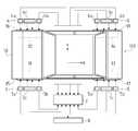
- FIG. 1is a block diagram illustrating an overall configuration of a vehicle stop state detection device according to an embodiment of the present invention.
- AThe left-side schematic diagram which shows the whole structure of a vehicle stop state detection apparatus,
- bThe left-side schematic diagram which shows the setting condition of the detection range in the detection method of a vehicle stop state.
- AThe right-side schematic diagram which shows the whole structure of a vehicle stop state detection apparatus,
- BThe right-side schematic diagram which shows the setting condition of the detection range in the detection method of a vehicle stop state.
- Itis a plane schematic diagram which shows the whole structure of a vehicle stop state detection apparatus.
- Itis a perspective view which shows the detection condition of the vehicle stop state by a vehicle stop state detection apparatus.
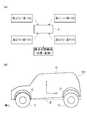
- FIG. 1is a block diagram illustrating an overall configuration of an alignment adjustment apparatus according to an embodiment of the present invention. It is a side surface schematic diagram which shows the whole structure of an alignment adjustment apparatus. It is a flowchart which shows the alignment adjustment operation
- FIG. 1is a block diagram showing the overall configuration of a vehicle stop state detection device according to an embodiment of the present invention
- FIG. 2is a schematic left side view showing the overall configuration of the vehicle stop state detection device according to an embodiment of the present invention.
- FIG. 3is a schematic right side view showing the overall configuration of the vehicle stop state detection device according to one embodiment of the present invention
- FIG. 4is a schematic plan view showing the overall configuration of the vehicle stop state detection device according to one embodiment of the present invention. It is. As shown in FIGS.
- a three-dimensional coordinate systemis defined, and the X-axis corresponding to the vehicle length (front-rear) direction and the vehicle width (left-right) ) Direction and a Z axis corresponding to the height (vertical) direction of the vehicle.
- the direction in which the vehicle moves backwardis the positive direction of the X axis
- the right direction in the forward direction of the vehicleis the positive direction of the Y axis
- the upward direction of the vehicleis the positive direction of the Z axis.
- the vehicle stop state detection device 1is a device for detecting the stop state of the vehicle, and includes a detection unit 2, a controller 7, a calculation device 8, and the like.
- the detection unit 2is a part for directly detecting the stop state of the vehicle that is the detection target, and is configured by a plurality of distance sensor groups 3, 4, 5, and 6.
- Each of the distance sensor groups 3, 4, 5 and 6includes a front distance sensor 3a, 4a, 5a and 6a, a rear distance sensor 3b, 4b, 5b and 6b, and an upper distance sensor 3c, 4c and 5c and 6c are provided.
- the controller 7receives signals detected by the above-described distance sensors (front distance sensors 3a, 4a, 5a, and 6a, rear distance sensors 3b, 4b, 5b, and 6b, and upper distance sensors 3c, 4c, 5c, and 6c).
- the distance sensorsare all connected to the controller 7. Further, the controller 7 is connected to an arithmetic device 8 constituted by a PC or the like.
- the calculation device 8incorporates a calculation program for calculating the stop state of the vehicle based on each signal input from the controller 7, and the basic data (for the vehicle type) required for calculating the stop state of the vehicle is incorporated.
- the corresponding vehicle body shape data, tire shape data, etc.)are stored in advance.
- the vehicle 100 to which the vehicle stop state detection method according to an embodiment of the present invention is appliedis directed in the forward direction (the negative direction of the X axis).
- a right rear tire 14 disposed on the right rear side and a body 10 supported by each of these tires 11, 12, 13, and 14are provided.
- the front portions 11a, 12a, 13a, and 14a, the rear portions 11b, 12b, 13b, and 14b, and the upper portions 11c, 12c, and 14aare shown as ranges indicating a part of each outer surface of each tire 11, 12, 13, and 14.
- a range called 13c ⁇ 14cis set.
- two horizontal tangent lines and two vertical tangent linesare set on the inner circumference of each tire 11, 12, 13, and 14, and each tire 11, 12, 13 is set.
- the outer surface surrounded by the rear arc of the vehicle, the upper and lower two horizontal tangents, and the rear vertical tangent of the outer circumference circle of each tire 11, 12, 13, and 14are defined as rear parts 11b, 12b, 13b, and 14b, respectively, and further, an arc on the vehicle upper side of the outer circumference circle of each tire 11, 12, 13, and 14 and the two front and rear vertical tangents.
- the upper surface 11c, 12c, 13c, and 14care defined as the ranges of the outer surfaces surrounded by the upper horizontal tangent line.
- each rangeie, each front part 11a, 12a, 13a, 14a, each rear part 11b, 12b, 13b, 14b and each upper part
- 11c, 12c, 13c, and 14ccan be set narrower. In this case, detection accuracy and detection speed (calculation speed) of detection points can be improved.
- a range showing a part of each outer surface of each of the fenders 15, 16, 17, and 18 formed in the body 10 of the vehicle 100.are set as the fender portions 15a, 16a, 17a, and 18a.
- the two front and rear vertical tangents set with respect to the inner circumference of each tire 11, 12, 13, and 14are enclosed.
- This rangeis defined as the fender portions 15a, 16a, 17a, and 18a. That is, the fender portions 15a, 16a, 17a, and 18a are set at the same position in the front-rear direction above the upper portions 11c, 12c, 13c, and 14c.
- fenders 15a, 16a, 17a and 18aare set more narrowly by predicting the range in which the detection points are obtained from the body shape data in advance.
- the detection accuracy and the detection speed (calculation speed)can be improved.
- the vehicle stop state detection device 1has a distance sensor (front distance) in each peripheral portion of the tires 11, 12, 13, and 14. Sensors 3a, 4a, 5a, 6a, rear distance sensors 3b, 4b, 5b, 6b and upper distance sensors 3c, 4c, 5c, 6c) are arranged.
- the distance sensor group 3is disposed in the peripheral portion of the left front tire 11 corresponding to the left front tire 11, and the front portion corresponding to the front portion 11 a of the outer surface of the left front tire 11.
- a distance sensor 3ais provided
- a rear distance sensor 3bis provided corresponding to the rear part 11b
- an upper distance sensor 3cis provided corresponding to the upper part 11c.
- the distance sensors 3a, 3b, and 3ccan scan the corresponding ranges (that is, the front part 11a, the rear part 11b, and the upper part 11c).
- a distance sensor group 4is disposed around the right front tire 12 so as to correspond to the right front tire 12, and a front portion corresponding to the front portion 12 a on the outer side surface of the right front tire 12.
- a distance sensor 4ais provided
- a rear distance sensor 4bis provided corresponding to the rear part 12b
- an upper distance sensor 4cis provided corresponding to the upper part 12c.
- each range sensornamely, front part 12a, rear part 12b, upper part 12c
- a distance sensor group 5is disposed around the left rear tire 13 so as to correspond to the left rear tire 13 and correspond to the front portion 13 a on the outer side surface of the left rear tire 13.
- the front distance sensor 5ais arranged
- the rear distance sensor 5bis arranged corresponding to the rear part 13b
- the upper distance sensor 5cis arranged corresponding to the upper part 13c.
- the distance sensors 5a, 5b, and 5ccan scan the corresponding ranges (that is, the front portion 13a, the rear portion 13b, and the upper portion 13c).
- a distance sensor group 6is disposed around the right rear tire 14 so as to correspond to the right rear tire 14 and correspond to the front portion 14 a on the outer surface of the right rear tire 14.
- the front distance sensor 6ais disposed
- the rear distance sensor 6bis disposed corresponding to the rear part 14b
- the upper distance sensor 6cis disposed corresponding to the upper part 14c.
- the distance sensors 6a, 6b, and 6ccan scan the corresponding ranges (that is, the front part 14a, the rear part 14b, and the upper part 14c).
- Each distance sensorincludes a non-contact type distance sensor. It is employed, and is arranged at a position separated from each tire 11, 12, 13, 14 by a predetermined distance. With such a configuration, the vehicle 100 can be easily positioned.
- FIG. 5is a perspective view showing a detection state of the vehicle stop state by the vehicle stop state detection device according to the embodiment of the present invention.
- the detection state of the vehicle stop state in the periphery of the left front tire 11will be described as an example for the respective tires 11, 12, 13, and 14, but each of the other tires 12, 13, and 14 will be described. Since the detection state of the vehicle stop state in the peripheral portion is the same as this, the description of the other tires 12, 13, and 14 is omitted for convenience.
- the front distance sensor 3ascans the entire front part 11a of the left front tire 11 and measures the distance from the front distance sensor 3a to the front part 11a. Then, the measurement result is input to the arithmetic device 8. And based on the measurement result by the front part distance sensor 3a, the calculation by the calculating apparatus 8 is made and the surface shape of the front part 11a is detected.
- the arithmetic device 8bulges most in the outer surface direction (the negative direction of the Y axis) of the left front tire 11 in the front portion 11a (in other words, A point A) that is closest to the front distance sensor 3a in the front portion 11a is detected.
- a point Athe outer surface direction of the left front tire 11 in the front portion 11a
- the arithmetic device 8bulges most in the outer surface direction (the negative direction of the Y axis) of the left front tire 11 in the front portion 11a (in other words, A point A) that is closest to the front distance sensor 3a in the front portion 11a is detected.
- a point A (11)In order to distinguish which tire the point A is detected for, what is detected for the front portion 11a of the left front tire 11 is hereinafter referred to as a point A (11).
- point A (12)what is detected for the front portion 12a of the right front tire 12
- point Athe front portion 13a of the left rear tire 13
- point A (14)
- the rear distance sensor 3bscans the rear part 11b of the left front tire 11 entirely, and the distance from the rear distance sensor 3b to the rear part 11b is measured. Then, the measurement result is input to the arithmetic device 8. And based on the measurement result by the rear part distance sensor 3b, the calculation by the calculating apparatus 8 is made and the surface shape of the rear part 11b is detected.
- the arithmetic device 8causes the rear portion 11b to bulge most in the outer surface direction (the negative direction of the Y axis) of the left front tire 11 (in other words, the rear portion 11b).
- the point B) closest to the rear distance sensor 3bis detected.
- a point B (11)in order to distinguish which tire the point B is detected for, what is detected for the rear portion 11b of the left front tire 11 is hereinafter referred to as a point B (11).
- a point B (12)what is detected for the rear portion 12b of the right front tire 12
- what is detected for the rear portion 13b of the left rear tire 13is described as a point B (13).
- What is detected with respect to the rear portion 14b of the right rear tire 14is referred to as a point B (14).
- the upper distance sensor 3cscans the entire upper part 11c of the left front tire 11 and measures the distance from the upper distance sensor 3c to the upper part 11c. . Then, the measurement result is input to the arithmetic device 8. And based on the measurement result of the upper part 11c by the upper distance sensor 3c, the calculation by the calculating apparatus 8 is made and the surface shape of the upper part 11c is detected.
- the arithmetic device 8causes the upper portion 11c to bulge the most in the outer surface direction of the left front tire 11 (the negative direction of the Y axis) (in other words, the upper portion 11c).
- the point C) closest to the upper distance sensor 3cis detected.
- a point C (11)in order to distinguish which tire the point C is detected for, what is detected for the upper part 11c of the left front tire 11 is hereinafter referred to as a point C (11).
- a point C (12)what is detected for the upper portion 12c of the right front tire 12
- what is detected for the upper portion 13c of the left rear tire 13is described as a point C (13).
- What is detected with respect to the upper portion 14c of the right rear tire 14is referred to as a point C (14).
- the upper distance sensor 3cscans the entire upper portion 11c, and simultaneously scans the entire fender portion 15a of the left front fender 15 to measure the distance from the upper distance sensor 3c to the fender portion 15a. Then, the measurement result is input to the arithmetic device 8. And based on the measurement result of the fender part 15a by the upper distance sensor 3c, the calculation by the arithmetic unit 8 is performed and the surface shape of the fender part 15a is detected.
- the arithmetic device 8causes the fender portion 15a to bulge most in the outer surface direction of the left front fender 15 (negative direction of the Y axis) (in other words, In the fender portion 15a, the point F) closest to the upper distance sensor 3c is detected.
- the one detected for the fender portion 15a of the left front fender 15is hereinafter referred to as a point F (15). To do.
- the upper distance sensors 3c, 4c, 5c, and 6calso serve as distance sensors (that is, fender portion distance sensors) for the fender portions 15a, 16a, 17a, and 18a.
- the number of distance sensors to be usedcan be reduced, and the vehicle stop state detection device 1 used in the vehicle stop state detection method can be made a simpler configuration.
- each distance sensorthat is, each front distance sensor 3a, 4a, 5a, 6a, each rear distance sensor 3b, 4b, 5b, 6b, and each upper distance sensor 3c, 4c, 5c, 6c).
- each front part 11a, 12a, 13a, 14a, each rear part 11b, 12b, 13b, 14b and each upper part 11c, 12c, 13c, 14cNecessary detection accuracy is secured. With such a configuration, the detection accuracy of the stop state of the vehicle 100 can be ensured.
- FIG. 6is an explanatory view showing a vehicle stop state detecting method according to an embodiment of the present invention
- FIG. 7is an explanatory view showing a vehicle stop state detecting method according to an embodiment of the present invention.
- the triangle S ⁇ b> 1is measured using the points A (11), B (11), and C (11) measured by the distance sensor group 3 and detected by the calculation device 8. It is formed.
- the arithmetic device 8calculates the three-dimensional coordinates of the center of gravity G (11) of the triangle S1, and uses the center of gravity G (11) as the evaluation point for the left front tire 11.
- the stop state of the left front tire 11is detected by using the three-dimensional coordinates of the center of gravity G (11) and the shape data of the left front tire 11 stored in advance in the calculation device 8.
- the concept of the stop stateincludes the stop position of the tire in the front-rear and left-right directions, the tire crushing condition caused by the increase or decrease in air pressure, the tire stop posture that changes depending on the tire turning angle (steering angle), etc. include.
- a triangle S2is formed by using the points A (13), B (13), and C (13) measured by the distance sensor group 4 and detected by the arithmetic unit 8.
- the arithmetic unit 8calculates the three-dimensional coordinates of the center of gravity G (12) of the triangle S2.
- the barycentric point G (12)is used as an evaluation point for the right front tire 12.
- the stop state of the right front tire 12is detected by using the three-dimensional coordinates of the center of gravity G (12) and the shape data of the right front tire 12 stored in advance in the arithmetic unit 8.
- a triangle S3is formed by using the points A (13), B (13), and C (13) measured by the distance sensor group 5 and detected by the arithmetic unit 8. Then, the three-dimensional coordinates of the center of gravity G (13) of the triangle S3 are calculated by the arithmetic unit 8. The barycentric point G (13) is used as an evaluation point for the left rear tire 13. Then, the stop state of the left rear tire 13 is detected by using the three-dimensional coordinates of the center of gravity G (13) and the shape data of the left rear tire 13 stored in advance in the arithmetic unit 8.
- a triangle S4is formed by using the point A (14), the point B (14), and the point C (14) measured by the distance sensor group 6 and detected by the arithmetic device 8 for the right rear tire 14. Then, the three-dimensional coordinates of the centroid point G (14) of the triangle S4 are calculated by the arithmetic unit 8.
- the barycentric point G (14)is used as an evaluation point for the right rear tire 14.
- the stop state of the right rear tire 14is detected by using the three-dimensional coordinates of the barycentric point G (14) and the shape data of the right rear tire 14 stored in advance in the arithmetic unit 8.
- the points F (15), F (16), and Fare detected. 17)
- the point F (18)is used as an evaluation point for each of the fenders 15, 16, 17 and 18, and the three-dimensional coordinates of the respective points F are compared with the shape data of the body 10 stored in advance in the arithmetic unit 8. Thus, the stop state of the body 10 is detected.
- the first point A (11), point A (12), point A (13), and point A (14)correspond to each other.
- the point B detected by the front distance sensors 3a, 4a, 5a, and 6a that scan the front portions 11a, 12a, 13a, and 14a on the outer side surfaces of the tires 11, 12, 13, and 14 (11), point B (12), point B (13), and point B (14)scan the rear portions 11b, 12b, 13b, and 14b on the outer side surfaces of the corresponding tires 11, 12, 13, and 14, respectively.
- the points C (11), C (12), C (13), and C (14), which are detected by the rear distance sensors 3b, 4b, 5b, and 6b,correspond to the corresponding tires 11.
- the points F (15), F (16), F (17), and F (18), which are detected by the distance sensors 3c, 4c, 5c, and 6c,correspond to the corresponding fenders 15 and 16, respectively.
- the detectionis performed by the upper distance sensors 3c, 4c, 5c, and 6c that function as fender-part distance sensors that scan 17 and 18.
- the stop state of the body 10 and the stop states of the tires 11, 12, 13, and 14can be detected independently. Therefore, for example, as shown in FIG. 7B, even when the vehicle 100 is in a stopped state in which only the body 10 is rotating around the Y axis (so-called pitch direction), it can be detected with high accuracy. it can.
- the present inventionis applied to a general vehicle having four wheels. However, if the present invention is applied, the number of tires (wheels) is other than four wheels. It is easy to apply to vehicles.
- the vehicle stop state detection device(that is, the vehicle stop state detection device 1) according to one embodiment of the present invention includes a plurality of tires (that is, the tires 11, 12, 13, and 14), and the tires 11 and 14 respectively. 12.
- a device for detecting a stop state of the vehicle 100including a body 10 on which a plurality of fenders corresponding to each of 12, 13 and 14 (that is, the respective fenders 15, 16, 17 and 18) are formed.
- a plurality of distance sensor groups corresponding to the tires 11, 12, 13, 14 and the fenders 15, 16, 17, 18(that is, the distance sensor groups 3, 4, 5, 6) and the distance sensor groups 3
- the front portion 11a on the outer surface of the left front tire 11 corresponding to the distance sensor group 3is scanned.
- Front part 1 In athe front distance sensor 3a that detects the coordinates of the portion of the left front tire 11 that bulges most outward in the lateral direction of the left front tire 11 as a first point A (11);
- the rear portion 11b of the outer side surface of the corresponding left front tire 11is scanned, and the coordinates of the portion of the rear portion 11b where the left front tire 11 bulges most outward in the lateral direction of the left front tire 11 are set to a second point B.
- the rear distance sensor 3b detected as (11) and the upper portion 11c of the outer surface of the left front tire 11 corresponding to the distance sensor group 3are scanned, and the left front tire 11 is laterally outward of the left front tire 11 in the upper portion 11c.
- the upper distance sensor 3cthat detects the coordinates of the part that bulges most towards the third point C (11), and the fender portion 15 of the left front fender 15 corresponding to the distance sensor group 3 In the fender portion 15a, and functions as a fender portion distance sensor that detects, as the fourth point F (15), the coordinates of the portion of the left front fender 15 that bulges most outward in the lateral direction of the body 10.
- the vehicle stop state detection methodcorresponds to each of a plurality of tires (that is, the tires 11, 12, 13, and 14) and the tires 11, 12, 13, and 14, respectively.
- the left front tire 11bulges most outward in the lateral direction of the left front tire 11 at the front portion 11a of the outer side surface of the left front tire 11.
- the left front tire 11bulges most outward in the lateral direction of the left front tire 11 at the rear portion 11b of the outer side surface of the left front tire 11.
- the part where the coordinates of the part are detected as the second point B (11) and the left front tire 11 bulges most outward in the lateral direction of the left front tire 11 in the upper part 11c of the outer side face of the left front tire 11Is detected as the third point C (11), and the center of gravity G (11) of the triangle S1 formed with the detected points A (11), B (11), and C (11) as vertices.
- the detected point F (15)is set as the evaluation point of the left front fender 15, and the evaluation points detected for the plurality of tires 11, 12, 13, and 14 by the arithmetic unit 8 (that is, The coordinates of the point G (11), the point G (12), the point G (13), the point G (14)) and the respective evaluation points (that is, the point F) detected for each of the fenders 15, 16, 17, 18 (15)
- the stop state of the vehicle 100is detected based on the coordinates of the point F (16), the point F (17), and the point F (18).
- the stop state of the vehicle 100can be detected regardless of the size and shape of the vehicle 100, and the stop state of the body 10 and the stop state of each tire 11, 12, 13, 14 can be detected. Since each can be detected, the stop state of the vehicle 100 can be detected with high accuracy.
- FIG. 8is a block diagram showing the overall configuration of the alignment adjustment apparatus according to one embodiment of the present invention
- FIG. 9is a schematic side view showing the overall configuration of the alignment adjustment apparatus according to one embodiment of the present invention.
- the alignment adjusting deviceis a device for adjusting a toe angle of a tire of a vehicle, and includes a toe angle detecting device for detecting the toe angle.
- This toe angle detecting deviceis only a device for detecting a toe angle, and the toe angle adjusting operation is not yet automated, and a configuration in which an adjusting operation is performed by an operator is general.
- the alignment adjusting device 20is provided with the vehicle stop state detecting device 1 described above, and further includes a control device 21, an adjusting device 22, a monitor 23, an operation switch 24, and the like.
- the above-described toe angle detection deviceis also used by the detection unit 2 provided in the vehicle stop state detection device 1.
- the control device 21is a device for controlling each part (for example, the adjuster 22) of the alignment adjusting device 20, and is connected to the arithmetic device 8. And the detection result of the stop state of the vehicle by the vehicle stop state detection device 1 is input from the arithmetic device 8 to the control device 21.
- the adjuster 22is a device that is controlled based on a control signal sent from the control device 21.
- the adjuster 22 shown in this embodimentincludes a slide portion 22a including a tool portion 22c that functions as a tool capable of tightening or loosening bolts, nuts, and the like, and the tool portion 22c.
- a robot portion 22bthat exhibits a function as a robot that guides the desired position to a desired position, and is controlled by the control device 21 to automatically adjust the degree of tightening of bolts, nuts, etc. existing at an arbitrary position. It is configured as a device that can.
- the adjuster 22having a simple mechanism including a mechanism for sliding the slide portion 22a along the guide 22d of the robot portion 22b is illustrated.
- the robot portion 22bis articulated. It is also possible to adopt a configuration such as a robot arm of a type, and it is also possible to have a configuration in which a tool portion is provided at the hand portion of the robot arm.
- the monitor 23is a display device connected to the control device 21, the detection result of the vehicle stop state by the vehicle stop state detection device 1 input to the control device 21 is displayed, and an operator who performs alignment adjustment It is the structure which can know the state etc. of a vehicle.
- the operation switch 24is a switch connected to the control device 21, and includes an operation unit 24 a that can be operated by an operator near the vehicle 100. Then, after the operator confirms the stop state of the vehicle and the like, the operator operates the operation switch 24 so that automatic control of the adjuster 22 by the control device 21 is permitted for the first time at that time. Is.
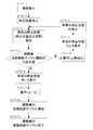
- FIG. 10is a work flow diagram showing alignment adjustment work by the alignment adjustment apparatus according to one embodiment of the present invention
- FIG. 11shows the automatic adjustment state (before adjustment) of the toe angle by the alignment adjustment apparatus according to one embodiment of the present invention
- FIG. 12is a schematic side view showing an automatic adjustment state (during adjustment) of the toe angle by the alignment adjusting apparatus according to the embodiment of the present invention.
- the operatoroperates the vehicle 100 and carries it into the alignment adjustment device 20 (STEP-1).
- the workerstops the vehicle 100 at a predetermined stop position while performing rough positioning (STEP-2).
- the stop state of the vehicle 100is detected by the vehicle stop state detection device 1 (STEP-3).
- a determinationis made based on the stop state of the vehicle 100 detected by the vehicle stop state detection device 1 (STEP-4).
- the arithmetic unit 8compares the stop state of the vehicle 100 detected by the vehicle stop state detector 1 with a predetermined (ideal) stop state determined by design, Judgment is performed by calculating each axis direction and the amount of deviation around each axis, and confirming whether each amount of deviation is less than a predetermined threshold. This determination is performed by the following formula 1.
- the amount of deviation of the front wheels in the X-axis direction(more specifically, the average value of the amounts of deviation of the left front tire 11 and the right front tire 12 in the X-axis direction) is ⁇ X F
- the amount of deviation of the rear wheels(more specifically, the left front tire 11
- ⁇ X Ris the average deviation amount in the X-axis direction of the right front tire 12
- ⁇ X Vis the deviation amount in the X-axis direction of the body
- the deviation angle of the front wheel about the X-axis (more specifically, the left front tire 11 and the right front tire) 12is the average deviation angle of the X-axis around the X axis)
- ⁇ XFthe deviation angle of the rear wheels (more specifically, the average deviation angle around the X-axis of the left front tire 11 and the right front tire 12) is ⁇ XR
- the deviation angle around the X axisis ⁇ ⁇
- the operation of the operation switch 24is invalidated. (STEP-5), the deviation amount is displayed on the monitor 23 (STEP-6), and the operator can correct the stop state of the vehicle 100 in which direction and at what distance. Information to determine whether or not.
- the workercorrects the stop state of the vehicle 100 based on the reference displayed on the monitor 23 (STEP-7), and the stop state of the vehicle 100 is detected again by the vehicle stop state detecting device 1 ( (STEP-3), (STEP-3) to (STEP-7) are repeatedly executed until the amount of deviation in each axial direction and around each axis becomes less than a predetermined threshold value.
- the tie rod 26 serving as a toe angle adjustment portionmay be disposed deep inside the recess 25 formed in the body 10, for example.
- the toolmay come into contact with the body 10 or the like. For this reason, the work of adjusting the toe angle has been performed by the worker each time. This has been a factor that hinders automation of alignment adjustment work.
- the vehicle stop statecan be accurately grasped by the vehicle stop state detection device 1, and therefore the adjuster 22 is inserted by the control device 21 based on information from the calculation device 8. It is possible to accurately adjust the position and angle to be performed.
- the slide portion 22 a of the adjusting machine 22can be inserted into the recess 25 without contacting the body 10 or the like, and the tie rod 26 disposed deep inside the recess 25.
- the tool portion 22c formed at the tip of the slide portion 22acan be accurately applied.
- the tie rod 26can be tightened or loosened by the adjuster 22 regardless of the operator.
- the operation of the adjuster 22can be controlled by the control device 21 to adjust the tightness of the tie rod 26. That is, by using the alignment adjusting device 20, it is possible to automate the toe angle adjustment work for the vehicle 100.
- the calculation device 8causes the vehicle stop state detection device 1 to detect the stop state of the vehicle 100 and the ideal stop state of the vehicle 100.
- the deviationis less than a predetermined threshold value x
- the alignment of the vehicle 100is automatically adjusted, and when the deviation exceeds the predetermined threshold value x, The stop state is adjusted.
- the alignment adjustment device 20includes the vehicle stop state detection device 1, and the stop state of the vehicle 100 based on the detection result of the stop state of the vehicle 100 by the vehicle stop state detection device 1. Is adjusted. With such a configuration, the stop state of the vehicle 100 can be detected with high accuracy regardless of the size and shape of the vehicle 100, so that the alignment adjustment work can be automated.
- the present inventioncan be suitably used for a technique for detecting a stop state of a vehicle such as an automobile. Furthermore, after detecting the stop state of a vehicle, it can utilize when performing operations, such as alignment adjustment operation
Landscapes
- Physics & Mathematics (AREA)
- General Physics & Mathematics (AREA)
- Length Measuring Devices By Optical Means (AREA)
- Length Measuring Devices With Unspecified Measuring Means (AREA)
Abstract
Description
Translated fromJapanese本発明は、車両の停止状態を検出する検出装置および検出方法と、その検出装置および検出方法を用いたアライメント調整装置の技術に関する。The present invention relates to a detection device and a detection method for detecting a stop state of a vehicle, and a technique of an alignment adjustment device using the detection device and the detection method.
自動車等の車両のアライメント調整を行う作業においては、車両をアライメント調整装置上の所定位置に停止させる必要がある。
車両をアライメント調整装置上の所定位置に位置決めする一般的な方法としては、車輪止めやガイドを用いた方法がある。係る方法では、車両の前後方向の基準となる位置に車輪止めを設け、作業者が車両を運転操作して、車輪止めに車輪(タイヤ)を当接させて車両を停止させることによって、車両の前後方向の位置決めを行う。また、車両の左右方向の基準となる位置にガイドを設け、作業者が車両を運転操作して、ガイドにタイヤを沿わせて車両を停止させることによって、車両の左右方向の位置決めを行っている。In the operation of adjusting the alignment of a vehicle such as an automobile, it is necessary to stop the vehicle at a predetermined position on the alignment adjustment device.
As a general method for positioning the vehicle at a predetermined position on the alignment adjusting device, there is a method using a wheel stopper or a guide. In such a method, a wheel stopper is provided at a position serving as a reference in the front-rear direction of the vehicle, and an operator operates the vehicle to bring the wheel (tire) into contact with the wheel stopper and stop the vehicle. Position in the front-rear direction. In addition, a guide is provided at a position that serves as a reference in the left-right direction of the vehicle, and an operator operates the vehicle to stop the vehicle along with a tire along the guide, thereby positioning the vehicle in the left-right direction. .
しかしながら、車両は車種ごとにタイヤの大きさや幅等が異なってくるため、従来の位置決め方法では、位置決め精度を確保することが困難であった。
このように、車両の停止位置にばらつきが生じるため、車両の外部や内部に配置されている調整部位に対して、調整用器具を周囲に接触させること無く自動的に宛がうことが困難となり、アライメントの調整作業を自動化することが出来なかった。つまり、アライメントの調整作業に代表されるように、車両に対して外部から調整用器具を所定位置にあてがうことが必要となる作業を自動化するためには、その前提として車両の停止状態を正確に検出することが求められる。ここでいう車両の停止状態とは、車両の停止位置および停止姿勢を含む概念である(以下においても同じ)。However, since the vehicle has different tire sizes, widths, and the like for each vehicle type, it has been difficult to ensure positioning accuracy with the conventional positioning method.
As described above, since the stop position of the vehicle varies, it is difficult to automatically contact the adjustment site arranged outside or inside the vehicle without bringing the adjustment tool into contact with the surrounding area. The alignment adjustment work could not be automated. That is, as represented by the alignment adjustment work, in order to automate the work that requires the adjustment tool to be applied to the vehicle from the outside to the predetermined position, the vehicle stop state is accurately set as the premise. It is required to detect. The stop state of the vehicle here is a concept including a stop position and a stop posture of the vehicle (the same applies hereinafter).
従来、車両の位置を検出する技術としては、例えば、以下に示す特許文献1にその技術が開示されている。
特許文献1に示された従来技術は、車両のタイヤが通過する位置にエリアセンサを配置しておき、エリアセンサの監視範囲をタイヤが通過する際に、エリアセンサの受光部位が遮られオフ信号となる時間を計測して信号処理装置に入力し、係る信号処理装置によって、オフ信号の長さから、タイヤの中心位置を特定することによって、車両位置を検出する構成としている。
しかしながら、係る特許文献1に示された従来技術でも、車両の停止状態を精度良く検出することが困難であった。
In the prior art disclosed in
However, even with the conventional technique disclosed in
本発明は、係る現状を鑑みてなされたものであり、例えば、アライメントの調整作業のような、停止状態の車両に対して外部から施す作業の自動化を実現するために、車両の停止状態を精度良く検出することができる技術を提供することを課題としている。The present invention has been made in view of the present situation. For example, in order to realize automation of work performed from the outside on a stopped vehicle, such as alignment adjustment work, the vehicle stopped state is accurately determined. It is an object to provide a technique that can be detected well.
本発明の解決しようとする課題は以上の如くであり、次にこの課題を解決するための手段を説明する。The problems to be solved by the present invention are as described above. Next, means for solving the problems will be described.
本発明の第一の態様に係る車両の停止状態検出装置は、複数のタイヤと、前記複数のタイヤのそれぞれに対応する複数のフェンダーが形成されるボディと、を備える車両の停止状態を検出するものであり、前記複数のタイヤおよび前記複数のフェンダーのそれぞれに対応する複数の距離センサ群と、前記複数の距離センサ群が接続される演算装置と、を備える。
前記各距離センサ群は、前記距離センサ群に対応する前記タイヤの外側面の前部を走査して、該前部において、前記タイヤが該タイヤの側面方向外側に向けて最も膨出している部位の座標を第一の点として検出する前部距離センサと、前記距離センサ群に対応する前記タイヤの外側面の後部を走査して、該後部において、前記タイヤが該タイヤの側面方向外側に向けて最も膨出している部位の座標を第二の点として検出する後部距離センサと、前記距離センサ群に対応する前記タイヤの外側面の上部を走査して、該上部において、前記タイヤが該タイヤの側面方向外側に向けて最も膨出している部位の座標を第三の点として検出する上部距離センサと、前記距離センサ群に対応する前記フェンダーを走査して、該フェンダーにおいて、該フェンダーが前記ボディの側面方向外側に向けて最も膨出している部位の座標を第四の点として検出するフェンダー部距離センサと、を備える。
前記演算装置によって、前記距離センサ群によって検出された前記第一、第二および第三の点を頂点として形成される三角形の重心点の座標から、前記タイヤの評価点を検出し、かつ、前記距離センサ群によって検出された前記第四の点の座標から、前記フェンダーの評価点を検出して、前記複数のタイヤについて検出されたそれぞれの評価点の座標と、前記複数のフェンダーについて検出されたそれぞれの評価点の座標と、に基づいて、前記車両の停止状態を検出する。A vehicle stop state detection device according to a first aspect of the present invention detects a vehicle stop state including a plurality of tires and a body in which a plurality of fenders corresponding to each of the plurality of tires are formed. A plurality of distance sensor groups corresponding to each of the plurality of tires and the plurality of fenders, and an arithmetic device to which the plurality of distance sensor groups are connected.
Each of the distance sensor groups scans a front portion of the outer side surface of the tire corresponding to the distance sensor group, and the portion of the front portion where the tire is most bulged toward the outer side in the lateral direction of the tire A front distance sensor for detecting the coordinates of the first point and a rear portion of the outer surface of the tire corresponding to the distance sensor group, and the tire is directed outward in the lateral direction of the tire at the rear portion. A rear distance sensor that detects the coordinates of the most swollen portion as a second point, and an upper portion of the outer surface of the tire corresponding to the distance sensor group, and the tire is the tire The upper distance sensor that detects the coordinates of the most bulging part toward the outer side in the lateral direction of the head as a third point, and the fender corresponding to the distance sensor group are scanned, and the fender Zehnder is and a fender portion a distance sensor for detecting the most bulging to the site are coordinates as a fourth point towards laterally outside of the body.
The arithmetic device detects the evaluation point of the tire from the coordinates of the center of gravity of the triangle formed with the first, second and third points detected by the distance sensor group as vertices, and From the coordinates of the fourth point detected by the distance sensor group, the evaluation points of the fender are detected, and the coordinates of the evaluation points detected for the plurality of tires and the plurality of fenders are detected. Based on the coordinates of the respective evaluation points, the stop state of the vehicle is detected.
本発明の実施の一形態において、前記上部距離センサは、前記フェンダー部距離センサを兼ねることが好ましい。In one embodiment of the present invention, it is preferable that the upper distance sensor also serves as the fender part distance sensor.
本発明の実施の一形態において、前記複数の距離センサ群は、非接触式の距離センサによって構成され、対応する前記複数のタイヤから所定の距離だけ離間した位置に配置されることが好ましい。In one embodiment of the present invention, it is preferable that the plurality of distance sensor groups are configured by non-contact distance sensors and are disposed at positions separated from the corresponding plurality of tires by a predetermined distance.
本発明の実施の一形態において、前記複数の距離センサ群は、レーザーセンサによって構成されることが好ましい。In one embodiment of the present invention, the plurality of distance sensor groups are preferably configured by laser sensors.
本発明の第二の態様に係る車両の停止状態検出方法は、複数のタイヤと、前記複数のタイヤのそれぞれに対応する複数のフェンダーが形成されるボディと、を備える車両の停止状態を検出する方法であり、前記複数のタイヤおよび前記複数のフェンダーのそれぞれに対応する複数の距離センサ群と、前記複数の距離センサ群が接続される演算装置と、を備え、前記タイヤの外側面の前部において、前記タイヤが該タイヤの側面方向外側に向けて最も膨出している部位の座標を第一の点として検出し、かつ、前記タイヤの外側面の後部において、前記タイヤが該タイヤの側面方向外側に向けて最も膨出している部位の座標を第二の点として検出し、かつ、前記タイヤの外側面の上部において、前記タイヤが該タイヤの側面方向外側に向けて最も膨出している部位の座標を第三の点として検出して、検出された前記第一、第二および第三の点を頂点として形成される三角形の重心点を前記タイヤの評価点とするとともに、前記フェンダーにおいて、前記フェンダーが前記ボディの側面方向外側に向けて最も膨出している部位の座標を第四の点として検出して、検出された前記第四の点を前記フェンダーの評価点とし、前記演算装置によって、前記複数のタイヤについて検出されたそれぞれの評価点の座標と、前記複数のフェンダーについて検出されたそれぞれの評価点の座標と、に基づいて、前記車両の停止状態を検出する。A vehicle stop state detection method according to a second aspect of the present invention detects a vehicle stop state including a plurality of tires and a body in which a plurality of fenders corresponding to each of the plurality of tires are formed. A plurality of distance sensor groups corresponding to each of the plurality of tires and the plurality of fenders, and an arithmetic unit to which the plurality of distance sensor groups are connected, and a front portion of an outer surface of the tire In the above, the coordinates of the portion of the tire that bulges most outward in the lateral direction of the tire are detected as a first point, and the tire is in the lateral direction of the tire at the rear portion of the outer surface of the tire. The coordinates of the portion that bulges outward most are detected as the second point, and the tire is located at the upper part of the outer side surface of the tire toward the outer side in the lateral direction of the tire. The coordinates of the bulging part are detected as a third point, and the center of gravity of the triangle formed with the detected first, second and third points as vertices is used as the evaluation point of the tire In the fender, the coordinates of the portion of the fender that bulges most outward in the lateral direction of the body is detected as a fourth point, and the detected fourth point is used as the evaluation point of the fender. The stop state of the vehicle is detected by the arithmetic unit based on the coordinates of the evaluation points detected for the plurality of tires and the coordinates of the evaluation points detected for the plurality of fenders. .
本発明の実施の一形態において、前記第一の点は、対応する前記タイヤの外側面の前部を走査する前部距離センサによって検出し、前記第二の点は、対応する前記タイヤの外側面の後部を走査する後部距離センサによって検出し、前記第三の点は、対応する前記タイヤの外側面の上部を走査する上部距離センサによって検出し、前記第四の点は、対応する前記フェンダーを走査するフェンダー部距離センサによって検出することが好ましい。In an embodiment of the present invention, the first point is detected by a front distance sensor that scans a front portion of the outer side surface of the corresponding tire, and the second point is outside the corresponding tire. The third point is detected by an upper distance sensor that scans the upper part of the outer side surface of the corresponding tire, and the fourth point is detected by the corresponding fender. It is preferable to detect by the fender part distance sensor which scans.
本発明の実施の一形態において、前記第四の点は、前記フェンダー部距離センサを兼ねる前記上部距離センサによって検出することが好ましい。In one embodiment of the present invention, it is preferable that the fourth point is detected by the upper distance sensor that also serves as the fender part distance sensor.
本発明の実施の一形態において、前記距離センサ群は、対応する前記複数のタイヤから所定の距離だけ離間した位置に配置され、非接触で前記第一、第二、第三および第四の点を検出することが好ましい。In an embodiment of the present invention, the distance sensor group is disposed at a position spaced apart from the corresponding plurality of tires by a predetermined distance, and the first, second, third, and fourth points are contactless. Is preferably detected.
本発明の実施の一形態において、前記距離センサ群は、レーザーセンサによって構成されることが好ましい。In one embodiment of the present invention, it is preferable that the distance sensor group includes a laser sensor.
本発明の第三の態様に係るアライメント調整装置は、本発明の第一の態様に係る車両停止状態の検出装置を備え、前記車両停止状態の検出装置による車両の停止状態の検出結果に基づいて、前記車両の停止状態を調整する。An alignment adjustment apparatus according to a third aspect of the present invention includes the vehicle stop state detection device according to the first aspect of the present invention, and is based on the detection result of the vehicle stop state by the vehicle stop state detection device. Then, the stop state of the vehicle is adjusted.
本発明の実施の一形態において、前記演算装置によって、前記検出装置による前記車両の停止状態の検出結果と、前記車両の理想的な停止状態とのズレを検出して、前記ズレが予め定めた閾値未満である場合には、前記車両のアライメントを自動調整し、前記ズレが予め定めた閾値を越えている場合には、前記車両の停止状態を調整することが好ましい。In one embodiment of the present invention, the arithmetic unit detects a deviation between a detection result of the stop state of the vehicle by the detection device and an ideal stop state of the vehicle, and the deviation is determined in advance. Preferably, the alignment of the vehicle is automatically adjusted when it is less than the threshold, and the stop state of the vehicle is adjusted when the deviation exceeds a predetermined threshold.
本発明の効果として、以下に示すような効果を奏する。As the effects of the present invention, the following effects are obtained.
本発明の第一の態様によれば、車両の大きさや形状に係わらず、車両の停止状態を検出することができ、また、ボディの停止状態と、タイヤの停止状態をそれぞれ検出することができるため、精度良く車両の停止状態を検出することができる。
また、使用する距離センサの数量を削減し、車両停止状態の検出装置をより簡易な構成とすることができる。
また、車両の位置決めを容易に行うことができる。
また、車両の停止状態の検出精度を確保することができる。According to the first aspect of the present invention, the stop state of the vehicle can be detected regardless of the size and shape of the vehicle, and the stop state of the body and the stop state of the tire can be detected respectively. Therefore, the stop state of the vehicle can be detected with high accuracy.
Further, the number of distance sensors to be used can be reduced, and the vehicle stop state detection device can be made simpler.
Further, the vehicle can be easily positioned.
Moreover, the detection accuracy of the stop state of the vehicle can be ensured.
本発明の第二の態様によれば、ボディの停止状態と、タイヤの停止状態をそれぞれ検出することができるため、精度良く車両の停止状態を検出することができる。
また、車両の大きさや形状に係わらず、車両の停止状態を検出することができる。
また、使用する距離センサの数量を削減し、車両停止状態の検出装置をより簡易な構成とすることができる。
また、車両の位置決めを容易に行うことができる。
また、車両の停止状態の検出精度を確保することができる。According to the second aspect of the present invention, since the stop state of the body and the stop state of the tire can be detected, the stop state of the vehicle can be detected with high accuracy.
Moreover, the stop state of the vehicle can be detected regardless of the size and shape of the vehicle.
Further, the number of distance sensors to be used can be reduced, and the vehicle stop state detection device can be made simpler.
Further, the vehicle can be easily positioned.
Moreover, the detection accuracy of the stop state of the vehicle can be ensured.
本発明の第三の態様によれば、車両の大きさや形状に係わらず、車両の停止状態を精度良く検出することができ、アライメント調整作業の自動化を実現することができる。
また、アライメント調整作業の際に、調整機がボディと接触することが防止できる。According to the third aspect of the present invention, it is possible to accurately detect the stop state of the vehicle regardless of the size and shape of the vehicle, and to realize automation of the alignment adjustment work.
Further, it is possible to prevent the adjuster from coming into contact with the body during the alignment adjustment work.
本発明の一実施形態に係る車両停止状態検出装置の全体構成について、図1~図4を用いて説明する。
図1は本発明の一実施形態に係る車両停止状態検出装置の全体構成を示すブロック図、図2は本発明の一実施形態に係る車両停止状態検出装置の全体構成を示す左側面模式図、図3は本発明の一実施形態に係る車両停止状態検出装置の全体構成を示す右側面模式図、図4は本発明の一実施形態に係る車両停止状態検出装置の全体構成を示す平面模式図である。
尚、図2~図4に示す如く、本実施形態では、説明の便宜上、三次元座標系を規定しており、車両の長さ(前後)方向に対応するX軸と、車両の幅(左右)方向に対応するY軸と、車両の高さ(上下)方向に対応するZ軸と、を規定している。そして、車両が後進する方向をX軸の正方向とし、車両の前進方向(X軸の負方向)に向かって右方向をY軸の正方向とし、車両の上方向をZ軸の正方向としている。An overall configuration of a vehicle stop state detection apparatus according to an embodiment of the present invention will be described with reference to FIGS.
FIG. 1 is a block diagram showing the overall configuration of a vehicle stop state detection device according to an embodiment of the present invention, and FIG. 2 is a schematic left side view showing the overall configuration of the vehicle stop state detection device according to an embodiment of the present invention. FIG. 3 is a schematic right side view showing the overall configuration of the vehicle stop state detection device according to one embodiment of the present invention, and FIG. 4 is a schematic plan view showing the overall configuration of the vehicle stop state detection device according to one embodiment of the present invention. It is.
As shown in FIGS. 2 to 4, in this embodiment, for convenience of explanation, a three-dimensional coordinate system is defined, and the X-axis corresponding to the vehicle length (front-rear) direction and the vehicle width (left-right) ) Direction and a Z axis corresponding to the height (vertical) direction of the vehicle. The direction in which the vehicle moves backward is the positive direction of the X axis, the right direction in the forward direction of the vehicle (the negative direction of the X axis) is the positive direction of the Y axis, and the upward direction of the vehicle is the positive direction of the Z axis. Yes.
図1に示す如く、車両停止状態検出装置1は、車両の停止状態を検出するための装置であり、検出部2、コントローラ7、演算装置8等を具備する。
検出部2は、検出対象物である車両の停止状態を直接検出するための部位であり、複数の距離センサ群3・4・5・6によって構成されている。そして、各距離センサ群3・4・5・6には、それぞれに前部距離センサ3a・4a・5a・6aと、後部距離センサ3b・4b・5b・6bと、上部距離センサ3c・4c・5c・6cが備えられている。As shown in FIG. 1, the vehicle stop
The
コントローラ7は、前述した各距離センサ(前部距離センサ3a・4a・5a・6a、後部距離センサ3b・4b・5b・6bおよび上部距離センサ3c・4c・5c・6c)によって検出された信号を集約し、各信号を同期処理することができる装置であり、各距離センサは、全てコントローラ7に接続されている。
また、コントローラ7は、PC等によって構成される演算装置8に接続されている。The
Further, the
演算装置8には、コントローラ7から入力される各信号に基づいて、車両の停止状態を算出する演算プログラムが組み込まれており、車両の停止状態を算出するために必要となる基本データ(車種に応じた車両のボディの形状データやタイヤの形状データ等)が予め記憶されている。The
図2(a)および図3(a)に示す如く、本発明の一実施形態に係る車両停止状態の検出方法の適用対象となる車両100は、前進方向(X軸の負方向)に対して、車両100の左前方に配設される左前タイヤ11と、車両100の右前方に配設される右前タイヤ12と、車両100の左後方に配設される左後タイヤ13と、車両100の右後方に配設される右後タイヤ14と、これらの各タイヤ11・12・13・14によって支持されているボディ10を備えている。As shown in FIG. 2A and FIG. 3A, the
本実施形態では、各タイヤ11・12・13・14の各外側面の一部を示す範囲として、前部11a・12a・13a・14a、後部11b・12b・13b・14b、上部11c・12c・13c・14c、と呼ぶ範囲を設定している。In the present embodiment, the
本実施形態では、各タイヤ11・12・13・14の内周円に対して上下2本の水平方向の接線と前後2本の鉛直方向の接線を設定して、各タイヤ11・12・13・14の外周円のうち車両の前方側の円弧と、前記上下2本の水平方向の接線と、前記前側の鉛直方向の接線と、によって囲まれる外側面の範囲をそれぞれ前部11a・12a・13a・14aと規定している。In the present embodiment, two horizontal tangent lines and two vertical tangent lines are set on the inner circumference of each
また、各タイヤ11・12・13・14の外周円のうち車両の後方側の円弧と、前記上下2本の水平方向の接線と、前記後側の鉛直方向の接線と、によって囲まれる外側面の範囲をそれぞれ後部11b・12b・13b・14bと規定し、さらに、各タイヤ11・12・13・14の外周円のうち車両の上方側の円弧と、前記前後2本の鉛直方向の接線と、前記上側の水平方向の接線と、によって囲まれる外側面の範囲をそれぞれ上部11c・12c・13c・14cと規定している。Also, the outer surface surrounded by the rear arc of the vehicle, the upper and lower two horizontal tangents, and the rear vertical tangent of the outer circumference circle of each
また、タイヤの形状データ等から、検出点が得られる範囲を予め予想することによって、各範囲(即ち、各前部11a・12a・13a・14a、各後部11b・12b・13b・14bおよび各上部11c・12c・13c・14c)をさらに狭めて設定することも可能であり、この場合、検出点の検出精度および検出速度(演算速度)の向上を図ることができる。Further, by predicting in advance the range in which detection points can be obtained from tire shape data, etc., each range (ie, each
また、本実施形態では、図2(a)および図3(a)に示す如く、車両100のボディ10に形成される各フェンダー15・16・17・18の各外側面の一部を示す範囲として、各フェンダー部15a・16a・17a・18aと呼ぶ範囲を設定している。Further, in the present embodiment, as shown in FIGS. 2A and 3A, a range showing a part of each outer surface of each of the
本実施形態では、各フェンダー15・16・17・18の外側面のうち、各タイヤ11・12・13・14の内周円に対して設定された前記前後2本の鉛直方向の接線によって囲まれる範囲を各フェンダー部15a・16a・17a・18aと規定している。即ち、各フェンダー部15a・16a・17a・18aは上部11c・12c・13c・14cの上方で、同じ前後方向の位置に設定している。In the present embodiment, among the outer surfaces of the
また、ボディの形状データ等から、検出点が得られる範囲を予め予想することによって、各フェンダー部15a・16a・17a・18aをさらに狭めて設定することも可能であり、この場合、検出点の検出精度および検出速度(演算速度)の向上を図ることができる。It is also possible to set the
そして、図2(b)、図3(b)および図4に示す如く、車両停止状態検出装置1では、各タイヤ11・12・13・14の各周辺部に、各距離センサ(前部距離センサ3a・4a・5a・6a、後部距離センサ3b・4b・5b・6bおよび上部距離センサ3c・4c・5c・6c)が配設される構成としている。As shown in FIGS. 2 (b), 3 (b), and 4, the vehicle stop
つまり、図2に示す如く、左前タイヤ11の周辺部には、該左前タイヤ11に対応させて距離センサ群3が配設され、左前タイヤ11の外側面の前部11aに対応させて前部距離センサ3aが配設され、後部11bに対応させて後部距離センサ3bが配設され、上部11cに対応させて上部距離センサ3cが配設されている。
そして、各距離センサ3a・3b・3cによって、それぞれに対応する各範囲(即ち、前部11a、後部11b、上部11c)を走査することが可能な構成としている。That is, as shown in FIG. 2, the
The
また、図3に示す如く、右前タイヤ12の周辺部には、該右前タイヤ12に対応させて距離センサ群4が配設され、右前タイヤ12の外側面の前部12aに対応させて前部距離センサ4aが配設され、後部12bに対応させて後部距離センサ4bが配設され、上部12cに対応させて上部距離センサ4cが配設されている。
そして、各距離センサ4a・4b・4cによって、それぞれに対応する各範囲(即ち、前部12a、後部12b、上部12c)を走査することが可能な構成としている。Further, as shown in FIG. 3, a
And each range sensor (namely,
また、図2に示す如く、左後タイヤ13の周辺部には、該左後タイヤ13に対応させて距離センサ群5が配設され、左後タイヤ13の外側面の前部13aに対応させて前部距離センサ5aが配設され、後部13bに対応させて後部距離センサ5bが配設され、上部13cに対応させて上部距離センサ5cが配設されている。
そして、各距離センサ5a・5b・5cによって、それぞれに対応する各範囲(即ち、前部13a、後部13b、上部13c)を走査することが可能な構成としている。In addition, as shown in FIG. 2, a
The
また、図3に示す如く、右後タイヤ14の周辺部には、該右後タイヤ14に対応させて距離センサ群6が配設され、右後タイヤ14の外側面の前部14aに対応させて前部距離センサ6aが配設され、後部14bに対応させて後部距離センサ6bが配設され、上部14cに対応させて上部距離センサ6cが配設されている。
そして、各距離センサ6a・6b・6cによって、それぞれに対応する各範囲(即ち、前部14a、後部14b、上部14c)を走査することが可能な構成としている。As shown in FIG. 3, a
The
また、各距離センサ(前部距離センサ3a・4a・5a・6a、後部距離センサ3b・4b・5b・6bおよび上部距離センサ3c・4c・5c・6c)には、非接触式の距離センサが採用されており、各タイヤ11・12・13・14から所定の距離だけ離間した位置に配置されている。
このような構成により、車両100の位置決めを容易に行うことができる。Each distance sensor (
With such a configuration, the
次に、車両停止状態検出装置1による車両停止状態の検出状況について、図5を用いて説明をする。
図5は本発明の一実施形態に係る車両停止状態検出装置による車両停止状態の検出状況を示す斜視図である。尚、ここでは各タイヤ11・12・13・14を代表して左前タイヤ11の周辺部における車両停止状態の検出状況を例示して説明をするが、その他の各タイヤ12・13・14の各周辺部における車両停止状態の検出状況はこれと同様であるため、その他の各タイヤ12・13・14に関する説明は、便宜上割愛している。Next, the detection state of the vehicle stop state by the vehicle stop
FIG. 5 is a perspective view showing a detection state of the vehicle stop state by the vehicle stop state detection device according to the embodiment of the present invention. Here, the detection state of the vehicle stop state in the periphery of the left
図5に示す如く、前部距離センサ3aによって、左前タイヤ11の前部11aが全面的に走査され、前部距離センサ3aから前部11aまでの距離が計測される。そして、この計測結果は、演算装置8に入力される。
そして、前部距離センサ3aによる計測結果に基づいて、演算装置8による演算がなされて、前部11aの表面形状が検出される。As shown in FIG. 5, the
And based on the measurement result by the front
さらに、検出された前部11aの表面形状に基づいて、演算装置8によって、前部11aにおいて、左前タイヤ11の外側面方向(Y軸の負方向)に最も膨出している点(言い換えれば、前部11aにおいて前部距離センサ3aとの距離が最も近い点)Aが検出される。尚、点Aが、どのタイヤに対して検出されたものかを区別するために、左前タイヤ11の前部11aに対して検出されたものは、以後、点A(11)と記載するものとする。同様に、右前タイヤ12の前部12aに対して検出されたものは点A(12)と記載し、左後タイヤ13の前部13aに対して検出されたものは点A(13)と記載し、右後タイヤ14の前部14aに対して検出されたものは点A(14)と記載する。Furthermore, based on the detected surface shape of the
また、前部距離センサ3aによる計測と同時に、後部距離センサ3bによって、左前タイヤ11の後部11bが全面的に走査され、後部距離センサ3bから後部11bまでの距離が計測される。そして、この計測結果は、演算装置8に入力される。
そして、後部距離センサ3bによる計測結果に基づいて、演算装置8による演算がなされて、後部11bの表面形状が検出される。Simultaneously with the measurement by the
And based on the measurement result by the rear
さらに、検出された後部11bの表面形状に基づいて、演算装置8によって、後部11bにおいて、左前タイヤ11の外側面方向(Y軸の負方向)に最も膨出している点(言い換えれば、後部11bにおいて後部距離センサ3bとの距離が最も近い点)Bが検出される。尚、点Bが、どのタイヤに対して検出されたものかを区別するために、左前タイヤ11の後部11bに対して検出されたものは、以後、点B(11)と記載するものとする。同様に、右前タイヤ12の後部12bに対して検出されたものは点B(12)と記載し、左後タイヤ13の後部13bに対して検出されたものは点B(13)と記載し、右後タイヤ14の後部14bに対して検出されたものは点B(14)と記載する。Further, based on the detected surface shape of the
さらに、前部距離センサ3aおよび後部距離センサ3bによる計測と同時に、上部距離センサ3cによって、左前タイヤ11の上部11cが全面的に走査され、上部距離センサ3cから上部11cまでの距離が計測される。そして、この計測結果は、演算装置8に入力される。
そして、上部距離センサ3cによる上部11cの計測結果に基づいて、演算装置8による演算がなされて、上部11cの表面形状が検出される。Further, simultaneously with the measurement by the
And based on the measurement result of the
さらに、検出された上部11cの表面形状に基づいて、演算装置8によって、上部11cにおいて、左前タイヤ11の外側面方向(Y軸の負方向)に最も膨出している点(言い換えれば、上部11cにおいて上部距離センサ3cとの距離が最も近い点)Cが検出される。尚、点Cが、どのタイヤに対して検出されたものかを区別するために、左前タイヤ11の上部11cに対して検出されたものは、以後、点C(11)と記載するものとする。同様に、右前タイヤ12の上部12cに対して検出されたものは点C(12)と記載し、左後タイヤ13の上部13cに対して検出されたものは点C(13)と記載し、右後タイヤ14の上部14cに対して検出されたものは点C(14)と記載する。Furthermore, based on the detected surface shape of the
また、上部距離センサ3cによって、上部11cを全面的に走査するのと同時に、左前フェンダー15のフェンダー部15aが全面的に走査され、上部距離センサ3cからフェンダー部15aまでの距離が計測される。そして、この計測結果は、演算装置8に入力される。
そして、上部距離センサ3cによるフェンダー部15aの計測結果に基づいて、演算装置8による演算がなされて、フェンダー部15aの表面形状が検出される。In addition, the
And based on the measurement result of the
さらに、検出されたフェンダー部15aの表面形状に基づいて、演算装置8によって、フェンダー部15aにおいて、左前フェンダー15の外側面方向(Y軸の負方向)に最も膨出している点(言い換えれば、フェンダー部15aにおいて上部距離センサ3cとの距離が最も近い点)Fが検出される。尚、点Fが、どのフェンダーに対して検出されたものかを区別するために、左前フェンダー15のフェンダー部15aに対して検出されたものは、以後、点F(15)と記載するものとする。同様に、右前フェンダー16のフェンダー部16aに対して検出されたものは点F(16)と記載し、左後フェンダー17のフェンダー部17aに対して検出されたものは点F(17)と記載し、右後フェンダー18のフェンダー部18aに対して検出されたものは点F(18)と記載する。Further, based on the detected surface shape of the
即ち、本実施形態では、各上部距離センサ3c・4c・5c・6cは、各フェンダー部15a・16a・17a・18aに対する距離センサ(即ち、フェンダー部距離センサ)を兼ねている。
このような構成により、使用する距離センサの数量を削減し、車両停止状態の検出方法に用いる車両停止状態検出装置1をより簡易な構成とすることができる。That is, in the present embodiment, the
With such a configuration, the number of distance sensors to be used can be reduced, and the vehicle stop
また、本実施形態では、各距離センサ(即ち、各前部距離センサ3a・4a・5a・6a、各後部距離センサ3b・4b・5b・6bおよび各上部距離センサ3c・4c・5c・6c)としてレーザーセンサを採用している。これにより、各範囲(即ち、各前部11a・12a・13a・14a、各後部11b・12b・13b・14bおよび各上部11c・12c・13c・14c)に現れる微小な形状変化を検出するために必要な検出精度を確保している。
このような構成により、車両100の停止状態の検出精度を確保することができる。In the present embodiment, each distance sensor (that is, each
With such a configuration, the detection accuracy of the stop state of the
次に、本発明の一実施形態に係る車両停止状態の検出方法について、図6および図7を用いて説明をする。
図6は本発明の一実施形態に係る車両の停止状態検出方法を示す説明図、図7は本発明の一実施形態に係る車両の停止状態検出方法を示す説明図である。Next, a vehicle stop state detection method according to an embodiment of the present invention will be described with reference to FIGS.
FIG. 6 is an explanatory view showing a vehicle stop state detecting method according to an embodiment of the present invention, and FIG. 7 is an explanatory view showing a vehicle stop state detecting method according to an embodiment of the present invention.
図6に示す如く、左前タイヤ11について、距離センサ群3によって計測され、演算装置8によって検出された点A(11)、点B(11)、点C(11)を用いて、三角形S1が形成される。
本実施形態では、演算装置8によって、三角形S1の重心点G(11)の三次元座標を算出し、この重心点G(11)を左前タイヤ11に対する評価点としている。そして、この重心点G(11)の三次元座標と演算装置8に予め記憶されている左前タイヤ11の形状データを用いることにより、左前タイヤ11の停止状態を検出する構成としている。
ここでいう停止状態の概念には、タイヤの前後左右方向の停止位置や、空気圧の増減等に起因するタイヤの潰れ具合や、タイヤの切れ角(舵角)等によって変化するタイヤの停止姿勢が含まれている。As shown in FIG. 6, for the left
In the present embodiment, the
Here, the concept of the stop state includes the stop position of the tire in the front-rear and left-right directions, the tire crushing condition caused by the increase or decrease in air pressure, the tire stop posture that changes depending on the tire turning angle (steering angle), etc. include.
また同様に、右前タイヤ12について、距離センサ群4によって計測され、演算装置8によって検出された点A(13)、点B(13)、点C(13)を用いて、三角形S2が形成され、演算装置8によって、三角形S2の重心点G(12)の三次元座標が算出される。この重心点G(12)を右前タイヤ12に対する評価点としている。そして、この重心点G(12)の三次元座標と演算装置8に予め記憶されている右前タイヤ12の形状データを用いることにより、右前タイヤ12の停止状態を検出する構成としている。Similarly, for the right
また同様に、左後タイヤ13について、距離センサ群5によって計測され、演算装置8によって検出された点A(13)、点B(13)、点C(13)を用いて、三角形S3が形成され、演算装置8によって、三角形S3の重心点G(13)の三次元座標が算出される。この重心点G(13)を左後タイヤ13に対する評価点としている。そして、この重心点G(13)の三次元座標と演算装置8に予め記憶されている左後タイヤ13の形状データを用いることにより、左後タイヤ13の停止状態を検出する構成としている。Similarly, for the left
また同様に、右後タイヤ14について、距離センサ群6によって計測され、演算装置8によって検出された点A(14)、点B(14)、点C(14)を用いて、三角形S4が形成され、演算装置8によって、三角形S4の重心点G(14)の三次元座標が算出される。この重心点G(14)を右後タイヤ14に対する評価点としている。そして、この重心点G(14)の三次元座標と演算装置8に予め記憶されている右後タイヤ14の形状データを用いることにより、右後タイヤ14の停止状態を検出する構成としている。Similarly, a triangle S4 is formed by using the point A (14), the point B (14), and the point C (14) measured by the
また、各フェンダー15・16・17・18について、各上部距離センサ3c・4c・5c・6cによって計測され、演算装置8によって検出された点F(15)、点F(16)、点F(17)、点F(18)を各フェンダー15・16・17・18についての評価点とし、この各点Fの三次元座標と演算装置8に予め記憶されているボディ10の形状データを比較することにより、ボディ10の停止状態を検出する構成としている。Further, for each of the
即ち、本発明の一実施形態に係る車両停止状態の検出方法においては、第一の点たる点A(11)、点A(12)、点A(13)、点A(14)は、対応する各タイヤ11・12・13・14の外側面の各前部11a・12a・13a・14aを走査する各前部距離センサ3a・4a・5a・6aによって検出し、第二の点たる点B(11)、点B(12)、点B(13)、点B(14)は、対応する各タイヤ11・12・13・14の外側面の各後部11b・12b・13b・14bを走査する各後部距離センサ3b・4b・5b・6bによって検出し、第三の点たる点C(11)、点C(12)、点C(13)、点C(14)は、対応する各タイヤ11・12・13・14の外側面の上部11c・12c・13c・14cを走査する各上部距離センサ3c・4c・5c・6cによって検出し、第四の点たる点F(15)、点F(16)、点F(17)、点F(18)は、対応する各フェンダー15・16・17・18を走査するフェンダー部距離センサとして機能する各上部距離センサ3c・4c・5c・6cによって検出している。
このような構成により、車両100の大きさや形状に係わらず、車両100の停止状態を検出することができるため、精度良く車両100の停止状態を検出することができる。That is, in the vehicle stop state detection method according to the embodiment of the present invention, the first point A (11), point A (12), point A (13), and point A (14) correspond to each other. The point B detected by the
With such a configuration, since the stop state of the
そして、図7(a)に示す如く、左前タイヤ11に対して検出された重心点G(11)と、右前タイヤ12に対して検出された重心点G(12)と、左後タイヤ13に対して検出された重心点G(13)と、右後タイヤ14に対して検出された重心点G(14)と、各フェンダー部15・16・17・18に対してそれぞれ検出された点F(15)・点F(16)・点F(17)・点F(18)の合計8点の三次元座標を総合的に用いて、演算装置8によって、車両100の停止状態を検出する構成としている。Then, as shown in FIG. 7A, the center of gravity G (11) detected for the left
また、本発明の一実施形態に係る車両停止状態の検出方法によれば、ボディ10の停止状態と、各タイヤ11・12・13・14の停止状態を、独立して検出することが可能となるため、例えば、図7(b)に示すように、ボディ10だけがY軸回り(所謂ピッチ方向)に回転しているような車両100の停止状態であっても、精度良く検出することができる。Further, according to the vehicle stop state detection method according to the embodiment of the present invention, the stop state of the
尚、本実施形態で示すように、本発明は一般的な4輪を有する車両に対して適用されるものであるが、本発明を応用すれば、タイヤ(車輪)の数量が4輪以外の車両に対して適用することも容易である。As shown in the present embodiment, the present invention is applied to a general vehicle having four wheels. However, if the present invention is applied, the number of tires (wheels) is other than four wheels. It is easy to apply to vehicles.
即ち、本発明の一実施形態に係る車両の停止状態検出装置(即ち、車両停止状態検出装置1)は、複数のタイヤ(即ち、各タイヤ11・12・13・14)と、各タイヤ11・12・13・14のそれぞれに対応する複数のフェンダー(即ち、各フェンダー15・16・17・18)が形成されるボディ10と、を備える車両100の停止状態を検出する装置であって、各タイヤ11・12・13・14および各フェンダー15・16・17・18のそれぞれに対応する複数の距離センサ群(即ち、各距離センサ群3・4・5・6)と、各距離センサ群3・4・5・6が接続される演算装置8と、を備え、例えば、距離センサ群3によって例示すれば、該距離センサ群3に対応する左前タイヤ11の外側面の前部11aを走査して、前部11aにおいて、左前タイヤ11が該左前タイヤ11の側面方向外側に向けて最も膨出している部位の座標を第一の点A(11)として検出する前部距離センサ3aと、距離センサ群3に対応する左前タイヤ11の外側面の後部11bを走査して、該後部11bにおいて、左前タイヤ11が該左前タイヤ11の側面方向外側に向けて最も膨出している部位の座標を第二の点B(11)として検出する後部距離センサ3bと、距離センサ群3に対応する左前タイヤ11の外側面の上部11cを走査して、該上部11cにおいて、左前タイヤ11が該左前タイヤ11の側面方向外側に向けて最も膨出している部位の座標を第三の点C(11)として検出する上部距離センサ3cと、距離センサ群3に対応する左前フェンダー15のフェンダー部15aを走査して、該フェンダー部15aにおいて、左前フェンダー15がボディ10の側面方向外側に向けて最も膨出している部位の座標を第四の点F(15)として検出するフェンダー部距離センサとして機能する上部距離センサ3cと、をそれぞれ備え、演算装置8によって、距離センサ群3によって検出された点A(11)、点B(11)、点C(11)を頂点として形成される三角形S1の重心点G(11)の座標から、左前タイヤ11の評価点(即ち、点G(11))を検出して、かつ、距離センサ群3によって検出された点F(15)の座標から、左前フェンダー15の評価点(即ち、点F(15))を検出して、左前タイヤ11について検出された評価点である点G(11)およびその他の各タイヤ12・13・14について検出されたそれぞれの評価点である点G(12)、点G(13)、点G(14)の座標と、左前フェンダー15について検出された評価点である点F(15)およびその他の各フェンダー16・17・18について検出されたそれぞれの評価点である点F(16)、点F(17)、点F(18)の座標と、に基づいて、車両100の停止状態を検出している。That is, the vehicle stop state detection device (that is, the vehicle stop state detection device 1) according to one embodiment of the present invention includes a plurality of tires (that is, the
また、本発明の一実施形態に係る車両停止状態の検出方法は、複数のタイヤ(即ち、各タイヤ11・12・13・14)と、各タイヤ11・12・13・14のそれぞれに対応する複数のフェンダー(即ち、各フェンダー15・16・17・18)が形成されるボディ10と、を備える車両100の停止状態を検出する方法であって、各タイヤ11・12・13・14および各フェンダー15・16・17・18のそれぞれに対応する複数の距離センサ群(即ち、各距離センサ群3・4・5・6)と、各距離センサ群3・4・5・6が接続される演算装置8と、を備え、例えば、左前タイヤ11について例示すると、該左前タイヤ11の外側面の前部11aにおいて、左前タイヤ11が該左前タイヤ11の側面方向外側に向けて最も膨出している部位の座標を第一の点A(11)として検出し、かつ、左前タイヤ11の外側面の後部11bにおいて、左前タイヤ11が該左前タイヤ11の側面方向外側に向けて最も膨出している部位の座標を第二の点B(11)として検出し、かつ、左前タイヤ11の外側面の上部11cにおいて、左前タイヤ11が該左前タイヤ11の側面方向外側に向けて最も膨出している部位の座標を第三の点C(11)として検出して、検出された点A(11)、点B(11)、点C(11)を頂点として形成される三角形S1の重心点G(11)を左前タイヤ11の評価点とするとともに、左前フェンダー15のフェンダー部15aにおいて、左前フェンダー15がボディ10の側面方向外側に向けて最も膨出している部位の座標を第四の点F(15)として検出して、検出された点F(15)を左前フェンダー15の評価点とし、演算装置8によって、複数の各タイヤ11・12・13・14について検出されたそれぞれの評価点(即ち、点G(11)、点G(12)、点G(13)、点G(14))の座標と、各フェンダー15・16・17・18について検出されたそれぞれの評価点(即ち、点F(15)、点F(16)、点F(17)、点F(18))の座標と、に基づいて、車両100の停止状態を検出している。In addition, the vehicle stop state detection method according to the embodiment of the present invention corresponds to each of a plurality of tires (that is, the
このような構成により、車両100の大きさや形状に係わらず、車両100の停止状態を検出することができ、また、ボディ10の停止状態と、各タイヤ11・12・13・14の停止状態をそれぞれ検出することができるため、精度良く車両100の停止状態を検出することができる。With such a configuration, the stop state of the
次に、本発明の一実施形態に係るアライメント調整装置について、図8および図9を用いて説明をする。
図8は本発明の一実施形態に係るアライメント調整装置の全体構成を示すブロック図、図9は本発明の一実施形態に係るアライメント調整装置の全体構成を示す側面模式図である。
アライメント調整装置は、車両のタイヤのトー角を調整するための装置であり、係るトー角を検出するためのトー角検出装置を備えている。このトー角検出装置は、あくまでトー角を検出するための装置であって、トー角の調整作業は、未だ自動化されておらず、作業者によって調整作業が行われる構成が一般的である。Next, an alignment adjustment apparatus according to an embodiment of the present invention will be described with reference to FIGS.
FIG. 8 is a block diagram showing the overall configuration of the alignment adjustment apparatus according to one embodiment of the present invention, and FIG. 9 is a schematic side view showing the overall configuration of the alignment adjustment apparatus according to one embodiment of the present invention.
The alignment adjusting device is a device for adjusting a toe angle of a tire of a vehicle, and includes a toe angle detecting device for detecting the toe angle. This toe angle detecting device is only a device for detecting a toe angle, and the toe angle adjusting operation is not yet automated, and a configuration in which an adjusting operation is performed by an operator is general.
図8に示す如く、アライメント調整装置20には、前述した車両停止状態検出装置1が備えられており、その他、制御装置21、調整機22、モニタ23、操作スイッチ24等から構成されている。尚、本実施形態では、車両停止状態検出装置1が備えている検出部2によって、前述したトー角検出装置を兼用する。As shown in FIG. 8, the
制御装置21は、アライメント調整装置20の各部(例えば、調整機22)を制御するための装置であり、演算装置8と接続されている。そして、演算装置8から、車両停止状態検出装置1による車両の停止状態の検出結果が、制御装置21に入力される。The
調整機22は、制御装置21から送られる制御信号に基づいて制御される装置である。図11に示す如く、本実施形態で示す調整機22は、ボルトやナット等を締めたり緩めたりすることができる工具としての機能を発揮する工具部22cを備えるスライド部22aと、係る工具部22cを所望する位置に導くロボットとしての機能を発揮するロボット部22bを備えており、制御装置21によって制御されて、任意の位置に存在するボルトやナット等の締め具合を自動的に調整することができる装置として構成されている。
尚、本実施形態では、ロボット部22bのガイド22dに沿って、スライド部22aがスライドする機構を備えた簡易な機構を有する調整機22を例示しているが、例えば、ロボット部22bを多関節型のロボットアームとするような構成も可能であり、該ロボットアームの手先部分に工具部を備える構成とすることも可能である。The
In the present embodiment, the
モニタ23は、制御装置21に接続されるディスプレイ装置であり、制御装置21に入力された車両停止状態検出装置1による車両の停止状態の検出結果等が表示され、アライメント調整を行う作業者が、車両の状態等を知ることができる構成としている。The
操作スイッチ24は、制御装置21に接続されるスイッチであり、車両100の近傍で作業者が操作することができる操作部24aを備えている。そして、作業者が車両の停止状態等を確認した上で、作業者が操作スイッチ24の操作を行うことによって、その時点で初めて制御装置21による調整機22の自動制御が許可される構成とするものである。The
次に、アライメント調整装置20によるアライメントの自動調整状況について、図10~図12を用いて説明をする。
図10は本発明の一実施形態に係るアライメント調整装置によるアライメント調整作業を示す作業フロー図、図11は本発明の一実施形態に係るアライメント調整装置によるトー角の自動調整状況(調整前)を示す側面模式図、図12は本発明の一実施形態に係るアライメント調整装置によるトー角の自動調整状況(調整中)を示す側面模式図である。Next, the automatic adjustment state of alignment by the
FIG. 10 is a work flow diagram showing alignment adjustment work by the alignment adjustment apparatus according to one embodiment of the present invention, and FIG. 11 shows the automatic adjustment state (before adjustment) of the toe angle by the alignment adjustment apparatus according to one embodiment of the present invention. FIG. 12 is a schematic side view showing an automatic adjustment state (during adjustment) of the toe angle by the alignment adjusting apparatus according to the embodiment of the present invention.
図10に示す如く、アライメント調整装置20によるアライメントの調整作業では、まず始めに、作業者が車両100を運転操作して、アライメント調整装置20に搬入する(STEP-1)。
次に、作業者はおおまかな位置決めをしつつ、車両100を所定の停止位置に停止させる(STEP-2)。As shown in FIG. 10, in the alignment adjustment work by the
Next, the worker stops the
次に、車両100を所定の停止位置に停止されると、車両停止状態検出装置1によって、車両100の停止状態が検出される(STEP-3)。
ここで、車両停止状態検出装置1によって検出された車両100の停止状態に基づく判定がなされる(STEP-4)。Next, when the
Here, a determination is made based on the stop state of the
この(STEP-4)では、演算装置8によって、車両停止状態検出装置1によって検出された車両100の停止状態と、設計上定められた所定の(理想的な)停止状態とを比較して、各軸方向および各軸周りのズレ量をそれぞれ算出し、各ズレ量が予め規定した閾値未満であるかを確認することによって判定を行っている。この判定は、以下に示す数式1によって行っている。In (STEP-4), the
ここでは、X軸に対する判定式を例示する。
尚、前輪のX軸方向のズレ量(より詳しくは、左前タイヤ11および右前タイヤ12のX軸方向のズレ量の平均値)をΔXF、後輪のズレ量(より詳しくは、左前タイヤ11および右前タイヤ12のX軸方向のズレ量の平均値)をΔXR、ボディのX軸方向のズレ量をΔXV、前輪のX軸回りのズレ角度(より詳しくは、左前タイヤ11および右前タイヤ12のX軸回りのズレ角度の平均値)をΔθXF、後輪のズレ角度(より詳しくは、左前タイヤ11および右前タイヤ12のX軸回りのズレ角度の平均値)をΔθXR、ボディのX軸回りのズレ角度をΔθXV、閾値をxとしている。Here, a determination formula for the X axis is illustrated.
Note that the amount of deviation of the front wheels in the X-axis direction (more specifically, the average value of the amounts of deviation of the left

そして、同様の判定をその他の軸(Y軸、Z軸)に対しても行って、各軸に対する判定のうちいずれか一つでも判定式を満足しない場合には、操作スイッチ24の操作を無効化した上で(STEP-5)、そのズレ量をモニタ23に表示して(STEP-6)、作業者が、どの方向に、どの程度の距離で、車両100の停止状態を修正すればよいかを判断するための情報を提示する。If the same determination is made for the other axes (Y axis, Z axis) and any one of the determinations for each axis does not satisfy the determination formula, the operation of the
そして、作業者が、モニタ23に表示された基準に基づいて、車両100の停止状態を修正し(STEP-7)、再度、車両停止状態検出装置1によって、車両100の停止状態が検出され(STEP-3)、各軸方向および各軸周りの各ズレ量が、全て予め規定した閾値未満となるまで、(STEP-3)~(STEP-7)が繰り返し実行される。Then, the worker corrects the stop state of the
また、各軸に対する判定をすべて満足した場合には、その旨をモニタ23に表示して(STEP-8)、作業者による操作スイッチ24の操作を促す。そして、作業者によって、操作スイッチ24の操作(例えば、操作部24aが引かれる)がなされると(STEP-9)、その後、制御装置21による調整機22の自動制御サイクルが開始される(STEP-10)。If all the determinations for each axis are satisfied, the fact is displayed on the monitor 23 (STEP-8), and the operator is prompted to operate the
図11に示す如く、アライメント調整作業において、トー角の調整部位となるタイロッド26は、例えば、ボディ10に形成されている凹部25の内部深くに配置されている場合がある。従来は、ロボット等で自動的にタイロッド26に工具を宛がおうとすると、車両100の停止状態が正確に把握されていないために、その工具がボディ10等に接触する可能性があった。このため、トー角を調整する作業は、その都度作業者によって行われていた。そしてこのことが、アライメント調整作業の自動化を阻害する要因となっていた。As shown in FIG. 11, in the alignment adjustment operation, the
アライメント調整装置20では、車両停止状態検出装置1によって、車両の停止状態を精度良く把握することが可能であるため、演算装置8からの情報に基づいて、制御装置21によって、調整機22を挿入するべき位置や角度を精度良く調整することが可能である。In the
そして、図12に示す如く、調整機22のスライド部22aを、凹部25に対して、ボディ10等に接触させることなく挿入することができ、そして、凹部25の内部深くに配置されるタイロッド26に対して、スライド部22a先端に形成されている工具部22cを、精度良く宛がうことが可能となっている。これにより、作業者によらず、調整機22によって、タイロッド26を締めたり緩めたりすることが可能となる。そして、検出部2によって、車両100のトー角をリアルタイムで検出しながら、制御装置21によって調整機22の動作を制御して、タイロッド26の締め具合を調整することが可能となる。つまり、アライメント調整装置20を用いることによって、車両100に対するトー角の調整作業を、自動化することが可能となる。Then, as shown in FIG. 12, the
以上のように、本発明の一実施形態に係るアライメント調整装置20では、演算装置8によって、車両停止状態検出装置1による車両100の停止状態の検出結果と、車両100の理想的な停止状態とのズレを検出して、前記ズレが予め定めた閾値x未満である場合には、車両100のアライメントを自動調整し、前記ズレが予め定めた閾値xを越えている場合には、車両100の停止状態を調整している。
このような構成により、アライメント調整作業の際に、調整機22がボディ10と接触することが防止できる。As described above, in the
With such a configuration, it is possible to prevent the
そして、車両100のトー角を調整する作業等が完了し、制御装置21による調整機22の自動制御サイクルが全て終了されると(STEP-11)、一連のアライメント調整装置20によるアライメントの自動調整作業が完了される。When the operation of adjusting the toe angle of the
即ち、本発明の一実施形態に係るアライメント調整装置20は、車両停止状態検出装置1を備え、該車両停止状態検出装置1による車両100の停止状態の検出結果に基づいて、車両100の停止状態を調整している。
このような構成により、車両100の大きさや形状に係わらず、車両100の停止状態を精度良く検出することができるため、アライメント調整作業の自動化を実現できる。That is, the
With such a configuration, the stop state of the
本発明は、自動車等の車両の停止状態を検出する技術に好適に利用できる。さらに、車両の停止状態を検出した後に、車両のアライメント調整作業等の作業を行う際に利用可能である。The present invention can be suitably used for a technique for detecting a stop state of a vehicle such as an automobile. Furthermore, after detecting the stop state of a vehicle, it can utilize when performing operations, such as alignment adjustment operation | work of a vehicle.
Claims (11)
Translated fromJapanese前記複数のタイヤおよび前記複数のフェンダーのそれぞれに対応する複数の距離センサ群と、
前記複数の距離センサ群が接続される演算装置と、を備え、
前記各距離センサ群は、
前記距離センサ群に対応する前記タイヤの外側面の前部を走査して、該前部において、
前記タイヤが該タイヤの側面方向外側に向けて最も膨出している部位の座標を第一の点として検出する前部距離センサと、
前記距離センサ群に対応する前記タイヤの外側面の後部を走査して、該後部において、
前記タイヤが該タイヤの側面方向外側に向けて最も膨出している部位の座標を第二の点として検出する後部距離センサと、
前記距離センサ群に対応する前記タイヤの外側面の上部を走査して、該上部において、
前記タイヤが該タイヤの側面方向外側に向けて最も膨出している部位の座標を第三の点として検出する上部距離センサと、
前記距離センサ群に対応する前記フェンダーを走査して、該フェンダーにおいて、該フェンダーが前記ボディの側面方向外側に向けて最も膨出している部位の座標を第四の点として検出するフェンダー部距離センサと、をそれぞれ備え、
前記演算装置によって、
前記距離センサ群によって検出された前記第一、第二および第三の点を頂点として形成される三角形の重心点の座標から、前記タイヤの評価点を検出し、かつ、
前記距離センサ群によって検出された前記第四の点の座標から、前記フェンダーの評価点を検出して、
前記複数のタイヤについて検出されたそれぞれの評価点の座標と、
前記複数のフェンダーについて検出されたそれぞれの評価点の座標と、に基づいて、
前記車両の停止状態を検出する車両停止状態の検出装置。An apparatus for detecting a stop state of a vehicle, comprising: a plurality of tires; and a body on which a plurality of fenders corresponding to each of the plurality of tires are formed.
A plurality of distance sensor groups corresponding to each of the plurality of tires and the plurality of fenders;
An arithmetic device to which the plurality of distance sensor groups are connected,
Each of the distance sensor groups is
Scan the front part of the outer surface of the tire corresponding to the distance sensor group, in the front part,
A front distance sensor that detects, as a first point, the coordinates of the portion of the tire that bulges most outward in the lateral direction of the tire;
Scan the rear part of the outer surface of the tire corresponding to the distance sensor group, and in the rear part,
A rear distance sensor that detects, as a second point, the coordinates of the portion of the tire that bulges most outward in the lateral direction of the tire;
By scanning the upper part of the outer surface of the tire corresponding to the distance sensor group,
An upper distance sensor that detects, as a third point, the coordinates of the portion of the tire that bulges most outward in the lateral direction of the tire;
A fender part distance sensor that scans the fender corresponding to the distance sensor group and detects, as a fourth point, the coordinates of a portion of the fender where the fender bulges most outward in the lateral direction of the body. And
By the arithmetic unit,
From the coordinates of the center of gravity of the triangle formed with the first, second and third points detected by the distance sensor group as vertices, the evaluation point of the tire is detected, and
From the coordinates of the fourth point detected by the distance sensor group, detect the evaluation point of the fender,
The coordinates of the respective evaluation points detected for the plurality of tires;
Based on the coordinates of each evaluation point detected for the plurality of fenders,
A vehicle stop state detection device for detecting a stop state of the vehicle.
非接触式の距離センサによって構成され、
対応する前記複数のタイヤから所定の距離だけ離間した位置に配置される請求項1または2に記載の車両停止状態の検出装置。The plurality of distance sensor groups are:
Consists of a non-contact type distance sensor,
The vehicle stop state detection device according to claim 1 or 2, wherein the vehicle stop state detection device is disposed at a position separated from the corresponding plurality of tires by a predetermined distance.
前記複数のタイヤおよび前記複数のフェンダーのそれぞれに対応する複数の距離センサ群と、前記複数の距離センサ群が接続される演算装置と、を備え、
前記タイヤの外側面の前部において、前記タイヤが該タイヤの側面方向外側に向けて最も膨出している部位の座標を第一の点として検出し、かつ、
前記タイヤの外側面の後部において、前記タイヤが該タイヤの側面方向外側に向けて最も膨出している部位の座標を第二の点として検出し、かつ、
前記タイヤの外側面の上部において、前記タイヤが該タイヤの側面方向外側に向けて最も膨出している部位の座標を第三の点として検出して、
検出された前記第一、第二および第三の点を頂点として形成される三角形の重心点を前記タイヤの評価点とするとともに、
前記フェンダーにおいて、前記フェンダーが前記ボディの側面方向外側に向けて最も膨出している部位の座標を第四の点として検出して、
検出された前記第四の点を前記フェンダーの評価点とし、
前記演算装置によって、前記複数のタイヤについて検出されたそれぞれの評価点の座標と、前記複数のフェンダーについて検出されたそれぞれの評価点の座標と、に基づいて、前記車両の停止状態を検出する車両停止状態の検出方法。A method for detecting a stop state of a vehicle comprising: a plurality of tires; and a body on which a plurality of fenders corresponding to each of the plurality of tires are formed.
A plurality of distance sensor groups corresponding to each of the plurality of tires and the plurality of fenders, and an arithmetic device to which the plurality of distance sensor groups are connected,
In the front part of the outer surface of the tire, the coordinates of the part where the tire is most bulged toward the outer side in the lateral direction of the tire are detected as a first point, and
In the rear part of the outer surface of the tire, the coordinates of the part where the tire bulges most outward in the lateral direction of the tire is detected as a second point, and
In the upper part of the outer side surface of the tire, the coordinates of the part where the tire bulges most outward in the lateral direction of the tire is detected as a third point,
The center of gravity of the triangle formed with the detected first, second and third points as vertices is used as the evaluation point of the tire,
In the fender, the coordinates of the part where the fender bulges most outward in the lateral direction of the body is detected as a fourth point,
The detected fourth point as an evaluation point of the fender,
A vehicle that detects a stop state of the vehicle based on the coordinates of the evaluation points detected for the plurality of tires and the coordinates of the evaluation points detected for the plurality of fenders by the arithmetic device. Stop state detection method.
前記第二の点は、対応する前記タイヤの外側面の後部を走査する後部距離センサによって検出し、
前記第三の点は、対応する前記タイヤの外側面の上部を走査する上部距離センサによって検出し、
前記第四の点は、対応する前記フェンダーを走査するフェンダー部距離センサによって検出する請求項5に記載の車両停止状態の検出方法。The first point is detected by a front distance sensor that scans the front of the corresponding outer surface of the tire,
The second point is detected by a rear distance sensor that scans the rear part of the outer surface of the corresponding tire,
The third point is detected by an upper distance sensor that scans the upper part of the outer surface of the corresponding tire,
The vehicle stop state detection method according to claim 5, wherein the fourth point is detected by a fender part distance sensor that scans the corresponding fender.
前記車両停止状態の検出装置による車両の停止状態の検出結果に基づいて、前記車両の停止状態を調整することを特徴とするアライメント調整装置。A vehicle stop state detection device according to any one of claims 1 to 4, comprising:
An alignment adjustment device that adjusts the stop state of the vehicle based on a detection result of the stop state of the vehicle by the detection device of the vehicle stop state.
前記検出装置による前記車両の停止状態の検出結果と、前記車両の理想的な停止状態とのズレを検出して、
前記ズレが予め定めた閾値未満である場合には、前記車両のアライメントを自動調整し、
前記ズレが予め定めた閾値を越えている場合には、前記車両の停止状態を調整することを特徴とする請求項10に記載のアライメント調整装置。By the arithmetic unit,
Detecting a deviation between a detection result of the stop state of the vehicle by the detection device and an ideal stop state of the vehicle;
When the deviation is less than a predetermined threshold, the vehicle alignment is automatically adjusted,
The alignment adjustment apparatus according to claim 10, wherein the stop state of the vehicle is adjusted when the deviation exceeds a predetermined threshold value.
Priority Applications (3)
| Application Number | Priority Date | Filing Date | Title |
|---|---|---|---|
| CA2737902ACA2737902C (en) | 2008-10-30 | 2009-10-27 | Device and method for detecting stopped state of vehicle, and alignment adjusting device |
| EP09823293.7AEP2352006B1 (en) | 2008-10-30 | 2009-10-27 | Device and method for detecting stopped state of vehicle, and alignment adjusting device |
| US13/062,393US8548769B2 (en) | 2008-10-30 | 2009-10-27 | Device and method for detecting stopped state of vehicle, and alignment adjusting device |
Applications Claiming Priority (2)
| Application Number | Priority Date | Filing Date | Title |
|---|---|---|---|
| JP2008280520AJP4530088B2 (en) | 2008-10-30 | 2008-10-30 | Vehicle stop state detection device, detection method, and alignment adjustment device |
| JP2008-280520 | 2008-10-30 |
Publications (1)
| Publication Number | Publication Date |
|---|---|
| WO2010050180A1true WO2010050180A1 (en) | 2010-05-06 |
Family
ID=42128550
Family Applications (1)
| Application Number | Title | Priority Date | Filing Date |
|---|---|---|---|
| PCT/JP2009/005653CeasedWO2010050180A1 (en) | 2008-10-30 | 2009-10-27 | Device and method for detecting stopped state of vehicle, and alignment adjusting device |
Country Status (5)
| Country | Link |
|---|---|
| US (1) | US8548769B2 (en) |
| EP (1) | EP2352006B1 (en) |
| JP (1) | JP4530088B2 (en) |
| CA (1) | CA2737902C (en) |
| WO (1) | WO2010050180A1 (en) |
Cited By (1)
| Publication number | Priority date | Publication date | Assignee | Title |
|---|---|---|---|---|
| WO2021065326A1 (en)* | 2019-09-30 | 2021-04-08 | マツダ株式会社 | Method and device for measuring vehicle wheel position |
Families Citing this family (3)
| Publication number | Priority date | Publication date | Assignee | Title |
|---|---|---|---|---|
| DE102010038905A1 (en)* | 2010-08-04 | 2012-02-09 | Robert Bosch Gmbh | Method and device for determining wheel and body movements of a vehicle |
| JP2019169059A (en)* | 2018-03-26 | 2019-10-03 | ヤンマー株式会社 | Travel area shape specification device |
| JP6949771B2 (en)* | 2018-03-29 | 2021-10-13 | ヤンマーパワーテクノロジー株式会社 | Travel area shape identification device |
Citations (5)
| Publication number | Priority date | Publication date | Assignee | Title |
|---|---|---|---|---|
| US5600435A (en)* | 1995-05-24 | 1997-02-04 | Fori Automation, Inc. | Intelligent sensor method and apparatus for an optical wheel alignment machine |
| EP0757229A2 (en)* | 1995-08-04 | 1997-02-05 | SCHENCK KOMEG GmbH | Device to determine without contact the height position of a motor vehicle |
| JPH11152060A (en)* | 1997-08-01 | 1999-06-08 | Corghi Spa | Attitude regulating method and device of motor vehicle |
| JP2003515157A (en)* | 1999-11-24 | 2003-04-22 | ナムローゼ フェンノートシャップ クリプトン エレクトロニック エンジニアリング | A method for measuring the dynamic behavior of a vehicle on a test bench |
| JP2007525682A (en)* | 2004-03-18 | 2007-09-06 | バイスバース ゲーエムベーハー | Wheel alignment measuring system and measuring method and measuring unit for determining the spatial position of a wheel rim |
Family Cites Families (6)
| Publication number | Priority date | Publication date | Assignee | Title |
|---|---|---|---|---|
| JP2000331281A (en) | 1999-05-19 | 2000-11-30 | Mitsubishi Heavy Ind Ltd | Vehicle discrimination device, vehicle discrimination method and parking lot facility |
| JP2001004344A (en) | 1999-06-25 | 2001-01-12 | Anzen Motor Car Co Ltd | Alignment measuring device for vehicle wheel |
| US6323776B1 (en)* | 1999-12-21 | 2001-11-27 | Snap-On Technologies, Inc. | Method and apparatus of automatically identifying faults in a machine vision measuring system |
| GB2366784B (en)* | 2000-06-14 | 2004-08-25 | Nippon Yusoki Co Ltd | Cargo handling vehicle |
| JP2003226259A (en) | 2002-02-06 | 2003-08-12 | Bridgestone Corp | Alignment adjustment method and adjustment support device for vehicle |
| JP5078306B2 (en)* | 2006-09-21 | 2012-11-21 | 本田技研工業株式会社 | Shift control device for motorcycle |
- 2008
- 2008-10-30JPJP2008280520Apatent/JP4530088B2/ennot_activeExpired - Fee Related
- 2009
- 2009-10-27WOPCT/JP2009/005653patent/WO2010050180A1/ennot_activeCeased
- 2009-10-27CACA2737902Apatent/CA2737902C/ennot_activeExpired - Fee Related
- 2009-10-27USUS13/062,393patent/US8548769B2/ennot_activeExpired - Fee Related
- 2009-10-27EPEP09823293.7Apatent/EP2352006B1/ennot_activeNot-in-force
Patent Citations (5)
| Publication number | Priority date | Publication date | Assignee | Title |
|---|---|---|---|---|
| US5600435A (en)* | 1995-05-24 | 1997-02-04 | Fori Automation, Inc. | Intelligent sensor method and apparatus for an optical wheel alignment machine |
| EP0757229A2 (en)* | 1995-08-04 | 1997-02-05 | SCHENCK KOMEG GmbH | Device to determine without contact the height position of a motor vehicle |
| JPH11152060A (en)* | 1997-08-01 | 1999-06-08 | Corghi Spa | Attitude regulating method and device of motor vehicle |
| JP2003515157A (en)* | 1999-11-24 | 2003-04-22 | ナムローゼ フェンノートシャップ クリプトン エレクトロニック エンジニアリング | A method for measuring the dynamic behavior of a vehicle on a test bench |
| JP2007525682A (en)* | 2004-03-18 | 2007-09-06 | バイスバース ゲーエムベーハー | Wheel alignment measuring system and measuring method and measuring unit for determining the spatial position of a wheel rim |
Cited By (5)
| Publication number | Priority date | Publication date | Assignee | Title |
|---|---|---|---|---|
| WO2021065326A1 (en)* | 2019-09-30 | 2021-04-08 | マツダ株式会社 | Method and device for measuring vehicle wheel position |
| JP2021056088A (en)* | 2019-09-30 | 2021-04-08 | マツダ株式会社 | Method and device for measuring wheel position of vehicle |
| CN114450551A (en)* | 2019-09-30 | 2022-05-06 | 马自达汽车株式会社 | Method and device for measuring wheel position of vehicle |
| JP7310507B2 (en) | 2019-09-30 | 2023-07-19 | マツダ株式会社 | Vehicle wheel position measuring method and device |
| CN114450551B (en)* | 2019-09-30 | 2023-12-01 | 马自达汽车株式会社 | Vehicle wheel position measuring method and vehicle wheel position measuring device |
Also Published As
| Publication number | Publication date |
|---|---|
| US20110161045A1 (en) | 2011-06-30 |
| EP2352006A1 (en) | 2011-08-03 |
| JP4530088B2 (en) | 2010-08-25 |
| EP2352006A4 (en) | 2012-05-30 |
| CA2737902C (en) | 2013-02-05 |
| US8548769B2 (en) | 2013-10-01 |
| JP2010107393A (en) | 2010-05-13 |
| EP2352006B1 (en) | 2013-04-24 |
| CA2737902A1 (en) | 2010-05-06 |
Similar Documents
| Publication | Publication Date | Title |
|---|---|---|
| US10976156B2 (en) | Rolling virtual wheel spindle calibration | |
| EP2332749B1 (en) | Method of and apparatus for determining geometrical dimension of a vehicle wheel comprising optical sensors | |
| US6256560B1 (en) | Method for correcting position of automated-guided vehicle and apparatus therefor | |
| US10322483B2 (en) | Tool shape measurement device and tool shape measurement method | |
| US8726708B2 (en) | Roller hemming device using robot manipulator with force sensor | |
| US20130071198A1 (en) | Numerically-controlled machine tool | |
| KR101684551B1 (en) | Mounting angle detection system of bsd sensor and the detection method | |
| US10654142B2 (en) | Device and method for checking and correcting the position of an operating device with respect to a piece | |
| JP4530088B2 (en) | Vehicle stop state detection device, detection method, and alignment adjustment device | |
| JP2021030315A (en) | On-machine measuring device, machine tool, and on-machine measuring method | |
| JP4646045B2 (en) | Parking assistance device | |
| JPH0392712A (en) | Three-dimensional position recognition by use of image processing device and distance measuring sensor | |
| CN108941848B (en) | Welding seam initial detection positioning system of plane autonomous mobile welding robot | |
| JP2773917B2 (en) | Work positioning device for bending equipment | |
| KR101541030B1 (en) | A measurement target for wheel alignment to prevent disturbance, a measurement system using the target and measuring method of the same | |
| CN115397631A (en) | Robot control device and control method, robot system, and device and method for generating robot operation program | |
| JP2001300875A (en) | Robot system | |
| KR20130039151A (en) | System and method controlling lane keeping assistance based tire force information | |
| JP2010139437A (en) | Vehicle confronting device and method for controlling vehicle confronting device | |
| JP5233703B2 (en) | Automatic toe angle adjusting device and control method thereof | |
| JP5279607B2 (en) | Positioning the hood on the car body | |
| JP6332510B2 (en) | Position detection method for automated guided vehicles | |
| JP7677745B1 (en) | Chassis dynamometer and method for controlling chassis dynamometer | |
| JP7644253B2 (en) | Robot System | |
| JP2021050522A5 (en) |
Legal Events
| Date | Code | Title | Description |
|---|---|---|---|
| 121 | Ep: the epo has been informed by wipo that ep was designated in this application | Ref document number:09823293 Country of ref document:EP Kind code of ref document:A1 | |
| WWE | Wipo information: entry into national phase | Ref document number:13062393 Country of ref document:US | |
| WWE | Wipo information: entry into national phase | Ref document number:2009823293 Country of ref document:EP | |
| WWE | Wipo information: entry into national phase | Ref document number:2737902 Country of ref document:CA | |
| NENP | Non-entry into the national phase | Ref country code:DE |