WO2010035831A1 - Cutting insert, cutting tool, and cutting method using cutting insert and cutting tool - Google Patents
Cutting insert, cutting tool, and cutting method using cutting insert and cutting toolDownload PDFInfo
- Publication number
- WO2010035831A1 WO2010035831A1PCT/JP2009/066784JP2009066784WWO2010035831A1WO 2010035831 A1WO2010035831 A1WO 2010035831A1JP 2009066784 WJP2009066784 WJP 2009066784WWO 2010035831 A1WO2010035831 A1WO 2010035831A1
- Authority
- WO
- WIPO (PCT)
- Prior art keywords
- cutting
- insert
- groove
- edge
- reference line
- Prior art date
- Legal status (The legal status is an assumption and is not a legal conclusion. Google has not performed a legal analysis and makes no representation as to the accuracy of the status listed.)
- Ceased
Links
Images


Classifications
- B—PERFORMING OPERATIONS; TRANSPORTING
- B23—MACHINE TOOLS; METAL-WORKING NOT OTHERWISE PROVIDED FOR
- B23C—MILLING
- B23C5/00—Milling-cutters
- B23C5/16—Milling-cutters characterised by physical features other than shape
- B23C5/20—Milling-cutters characterised by physical features other than shape with removable cutter bits or teeth or cutting inserts
- B23C5/202—Plate-like cutting inserts with special form
- B—PERFORMING OPERATIONS; TRANSPORTING
- B23—MACHINE TOOLS; METAL-WORKING NOT OTHERWISE PROVIDED FOR
- B23C—MILLING
- B23C2200/00—Details of milling cutting inserts
- B23C2200/12—Side or flank surfaces
- B23C2200/128—Side or flank surfaces with one or more grooves
- B—PERFORMING OPERATIONS; TRANSPORTING
- B23—MACHINE TOOLS; METAL-WORKING NOT OTHERWISE PROVIDED FOR
- B23C—MILLING
- B23C2200/00—Details of milling cutting inserts
- B23C2200/20—Top or side views of the cutting edge
- B23C2200/205—Discontinuous cutting edges
- Y—GENERAL TAGGING OF NEW TECHNOLOGICAL DEVELOPMENTS; GENERAL TAGGING OF CROSS-SECTIONAL TECHNOLOGIES SPANNING OVER SEVERAL SECTIONS OF THE IPC; TECHNICAL SUBJECTS COVERED BY FORMER USPC CROSS-REFERENCE ART COLLECTIONS [XRACs] AND DIGESTS
- Y10—TECHNICAL SUBJECTS COVERED BY FORMER USPC
- Y10T—TECHNICAL SUBJECTS COVERED BY FORMER US CLASSIFICATION
- Y10T407/00—Cutters, for shaping
- Y10T407/19—Rotary cutting tool
- Y10T407/1906—Rotary cutting tool including holder [i.e., head] having seat for inserted tool
- Y10T407/1908—Face or end mill
- Y10T407/1924—Specified tool shape
- Y—GENERAL TAGGING OF NEW TECHNOLOGICAL DEVELOPMENTS; GENERAL TAGGING OF CROSS-SECTIONAL TECHNOLOGIES SPANNING OVER SEVERAL SECTIONS OF THE IPC; TECHNICAL SUBJECTS COVERED BY FORMER USPC CROSS-REFERENCE ART COLLECTIONS [XRACs] AND DIGESTS
- Y10—TECHNICAL SUBJECTS COVERED BY FORMER USPC
- Y10T—TECHNICAL SUBJECTS COVERED BY FORMER US CLASSIFICATION
- Y10T407/00—Cutters, for shaping
- Y10T407/23—Cutters, for shaping including tool having plural alternatively usable cutting edges
- Y—GENERAL TAGGING OF NEW TECHNOLOGICAL DEVELOPMENTS; GENERAL TAGGING OF CROSS-SECTIONAL TECHNOLOGIES SPANNING OVER SEVERAL SECTIONS OF THE IPC; TECHNICAL SUBJECTS COVERED BY FORMER USPC CROSS-REFERENCE ART COLLECTIONS [XRACs] AND DIGESTS
- Y10—TECHNICAL SUBJECTS COVERED BY FORMER USPC
- Y10T—TECHNICAL SUBJECTS COVERED BY FORMER US CLASSIFICATION
- Y10T409/00—Gear cutting, milling, or planing
- Y10T409/30—Milling
- Y10T409/303752—Process
Definitions
- the present inventionrelates to a cutting insert, a cutting tool, and a cutting method using them, which are used for processing metal or the like.
- Patent Document 1As a cutting insert used for such a cutting tool, for example, Patent Document 1 includes a cutting blade located at an intersection of an upper surface and a side surface, and a groove portion reaching the upper surface so as to divide the cutting blade. A cutting insert is disclosed. Moreover, this groove part is inclined and provided in one direction with respect to the virtual line orthogonal to a cutting blade in side view. Therefore, the contact between the groove and the work material is suppressed by mounting the cutting insert on the holder so that the cutting edge has a positive axial rake and the groove is substantially parallel to the rotation trajectory of the cutting tool. Smooth cutting is possible.
- An object of the present inventionis to provide a cutting insert excellent in versatility and economy that can be used for any of cutting tools having different rotation directions at the time of cutting.
- the cutting insert of the present inventionincludes an upper surface, a lower surface, a side surface that connects the upper surface and the lower surface, a cutting blade that is located at an intersection of the upper surface and the side surface, A groove portion extending toward the lower surface and dividing the cutting blade.
- This groove parthas the 1st edge part and 2nd edge part which are located in the edge part of the width direction of this groove part, and are extended toward the said lower surface from the said upper surface.
- the first edge portionis located on the upper surface side in a side view, and has a first separation portion that moves away from a reference line that is substantially perpendicular to the lower surface that passes through the midpoint in the width direction of the groove portion as it approaches the lower surface. is doing.
- the second edge portionis located on the upper surface side in a side view, and has a second separation portion that moves away from the reference line as it approaches the lower surface.
- the cutting tool of the present inventionincludes a holder and the cutting insert attached to the tip of the holder.
- the cutting method of the work material of the present inventionincludes a step of rotating the cutting tool, a step of bringing the cutting tool into contact with the cutting tool in a rotated state, and the cutting tool from the work material. And a step of separating.
- the cutting insert of the present inventionit is possible to prevent the wall surface of the groove portion from coming into contact with the work material even when any of two types of cutting tools having different rotation directions at the time of cutting is used.
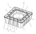
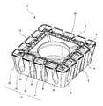
- FIG. 1is an overall perspective view of a cutting insert 1 according to a first embodiment of the present invention. It is (a) top view and (b) side view of the insert 1 of FIG. It is a principal part enlarged view of FIG.2 (b). It is a whole perspective view of cutting insert 1 'by a 2nd embodiment of the present invention.
- FIG. 5Ais a plan view and FIG. 5B is a side view of the insert 1 ′ in FIG. 4.
- 1is an overall perspective view of a cutting tool 10 according to an embodiment of the present invention. It is process drawing explaining the cutting method of the cut material by one Embodiment of this invention.
- the insert 1has an upper surface 2, a lower surface 3, and a side surface 4 connecting the upper surface 2 and the lower surface 3.
- the upper surface 2has a first side 21 and has a substantially polygonal shape.
- the upper surface 2has a substantially square shape.
- the insert 1has a cutting edge 5 and a groove 6.
- the cutting edge 5is provided along the first side 21 at the intersection of the upper surface 2 and the side surface 4.
- the groove portion 6is provided on the side surface 4 so as to extend from the upper surface 2 toward the lower surface 3 so as to divide the cutting blade 5.
- the area inward from the cutting edge 5 on the upper surface 2functions as a rake face. Moreover, the area which goes to the lower surface from the cutting edge 5 among the side surfaces 4 functions as a flank.
- the side surface 4is inclined so as to be located inward as it goes to the lower surface 2. That is, the insert 1 is a so-called positive type insert in which a positive clearance angle ⁇ is given to the side surface 4 that functions as a clearance surface. From the viewpoint of easily having a positive clearance angle when the insert 1 is mounted on the holder and maintaining the strength of the insert, the clearance angle ⁇ is preferably 5 degrees to 30 degrees.
- the upper surface 2is substantially square as described above, has four sides, and the cutting edges 5 are provided along these four sides. Therefore, this insert 1 is a so-called four-corner insert having four cutting edges 5.
- the cutting blade 5is divided into four small cutting blades 51 by the three groove portions 6. By cutting the cutting blade 5 in this way, the cutting resistance of the cutting blade applied during cutting can be reduced.
- all the groove portions 6have the same shape.
- the wall surface 7 of the groove 6has a first edge 71 and a second edge 72 extending from the upper surface 2 toward the lower surface 3 in a side view.
- the first edge 71 and the second edge 72are each an intersection edge between the wall surface 7 of the groove 6 and the side surface 3.
- the first edge 71 and the second edge 72are the wall surface of the groove 6.
- the regionmay be in a range from the intersection ridge between 7 and the side surface 3 to about 20% of the depth of the groove 6 along the wall surface 7.
- the first edge 71is located on one side with respect to the reference line L.
- the second edge 72is located on the other side with respect to the reference line L.
- the reference line Lis a line perpendicular to the lower surface 3 passing through the midpoint M, where M is the midpoint of the wall surface 7 of the groove 6 in the direction along the first side 21 (width direction).
- the midpoint Mrefers to the midpoint at the upper end of the wall surface 7 of the groove 6. That is, the reference line L is located between the first edge 71 and the second edge 72.
- the first edge portion 71has a separation portion 71 ⁇ / b> A provided on the upper surface 2 side so as to move away from the reference line L as it goes from the upper surface 2 to the lower surface 3 in a side view.
- the second edge portion 72also has a separation portion 72 ⁇ / b> A provided on the upper surface 2 side so as to move away from the reference line L as it goes from the upper surface 2 to the lower surface 3. That is, in the side view, an area where the width of the groove 6 increases from the upper surface 2 toward the lower surface 3 is provided on the upper surface 2 side of the groove 6.
- the separation portion 71A of the first edge portion 71 and the separation portion 72A of the second edge portion 72are preferably symmetric with respect to the reference line L as shown in FIG. Thereby, while suppressing that the groove part 6 contacts a workpiece, the intensity
- the separation portion 71A and the separation portion 72Aare each linear in a side view.
- the cutting bladehas a positive axial rake, and the longitudinal direction of the groove is substantially parallel to the rotation trajectory of the tool. Since an insert can be arrange
- both the first edge portion 71 and the second edge portion 72have the proximity portion B (71 ⁇ / b> B and 72 ⁇ / b> B) on the lower surface 3 side of the separation portion A.
- the proximity portions Bare provided so as to approach the reference line L as they approach the lower surface 3 in a side view. That is, in the side view, an area where the width of the groove 6 decreases from the upper surface 2 toward the lower surface 3 is provided on the lower surface 3 side of the groove 6.
- the insert 1is stably fixed to the holder, and the processing accuracy of the work material is improved.
- the proximity portion 71 ⁇ / b> B and the proximity portion 72 ⁇ / b> Beach have a curved shape.
- the first edge portion 71has the separation portion 71A located on the upper surface 2 side and the proximity portion 71B located on the lower surface 3 side.
- the first edge portion 71is in proximity to the separation portion 71A.
- Part 71Bis connected.
- the separation portion 72A and the proximity portion 72Bare connected.
- the inclination angle of the separating portion 71A with respect to the reference line Lis ⁇ 71A
- the inclination angle of the proximity portion 71B with respect to the reference lineis ⁇ 71B.
- the inclination angle of the separation portion 72A with respect to the reference line Lis ⁇ 72A
- the inclination angle of the proximity portion 72B with respect to the reference lineis ⁇ 72B.
- ⁇ 71A and ⁇ 72Acan be obtained, for example, as follows.
- ⁇ 71Ais obtained by an angle formed by the virtual extension line of the separation portion 71A and the reference line L as shown in FIG.
- the separating portion 71Ahas a curved shape in a side view, it is obtained by an angle formed by the tangent line at the upper end and the reference line L.
- ⁇ 71A and ⁇ 72Aare preferably set to 10 to 30 degrees from the viewpoint of maintaining the strength of the insert.
- ⁇ 71A ⁇ 72A12 degrees.
- ⁇ 71B and ⁇ 72Bcan be obtained in the same manner as ⁇ 71A as shown in FIG. ⁇ 71B and ⁇ 72B are preferably set to 5 to 25 degrees from the viewpoint of maintaining the strength of the insert.
- the width 6 of the groove 6is maximum at the midpoint position between the upper surface 2 and the lower surface 3 in a side view. That is, when the distance between the upper surface 2 and the lower surface 3 is a distance D, the maximum value Wmax of the width W of the groove 6 corresponds to the width at the midpoint of the distance D.
- the insert 1 ′ according to the second embodimentis different from the insert 1 according to the first embodiment in the shape of the groove 6 and the groove 6 provided in one cutting blade 5.
- the numberis different.
- the cutting blade 5is divided into five small cutting blades 51.
- the cutting tool 10 described lateris obtained by combining the insert 1 and the insert 1 ′ having different arrangements of the groove portions 6 in the cutting blade 5 and mounting them in the holder.
- the shape of the two groove portions 6I located on the inner side of the four groove portions 6is different from that of the two groove portions 6II located on the outer side.
- the groove 6Ihas substantially the same shape as the groove 6 in the insert 1 of the first embodiment described above.
- the groove 6Iis provided on the side surface 4 so as to reach the lower surface 3.
- the groove 6IIdoes not reach the lower surface 3. That is, the lower end of the groove 6II is located on the side surface 4. Since the groove 6II does not reach the lower surface, the strength of the insert side surface 4 can be maintained as compared with the groove 6I.
- the groove 6IIcan have both the effect of reducing the cutting resistance and the effect of maintaining the strength of the side surface 4 high.
- the width W of the groove part 6is the maximum at the midpoint of the distance D between the upper surface 2 and the lower surface 3 like the insert 1 of the first embodiment described above.
- a dimension in a direction substantially perpendicular to the lower surface 3 of the separation portion 71A of the first edgeis d71A
- a dimension substantially perpendicular to the lower surface 3 of the proximity portion 71B of the first edgeis d71B.
- the groove 6Isatisfies d71A ⁇ d71B
- the groove 6IIsatisfies d71A> d71B.
- the groove 6Iis d72A ⁇ d72B
- the groove 6IIis d72A> d72B.
- the inserts of the two embodimentshave been exemplified, but the present invention is not limited to these.
- the upper surfacemay be another shape such as a rhombus or a triangle.
- the first edge 71 and the second edge 72may be asymmetric with respect to the reference line L.
- at least one of the first edge portion and the second edge portionmay have an area provided so as to be substantially parallel to the reference line L between the separation portion A and the proximity portion B. .
- the cutting tool 10 of the present embodimentincludes a holder 11 and the above-described insert 1 and insert 1 ′.
- the insert 1 and the insert 1 ′are attached to the tip of the holder 11. Specifically, by inserting a fixing screw 91 into the through hole 90 of the insert 1 and screwing the tip of the fixing screw 91 into a screw hole (not shown) formed in the insert pocket 12 of the holder 11, An insert 1 ′ is attached to the holder 11. At this time, both the insert 1 and the insert 1 ′ are mounted on the holder 11 such that the cutting blade 5 protrudes from the tip surface of the holder 11.
- the insert 1 and the insert 1 ′are alternately mounted in the circumferential direction by two each. At this time, the insert 1 and the insert 1 ′ are mounted on the holder 11 so that the lower surface 3 is inclined with respect to the axis of the holder 11. That is, the insert 1 and the insert 1 ′ are attached to the holder 11 with an axial rake.
- the cutting tool 11is used by rotating clockwise during cutting. Since such a cutting tool 11 has the insert 1 and the insert 1 ′ described above, the wall surface 7 of the groove 6 can be prevented from coming into contact with the work material. Therefore, the cutting resistance at the time of cutting can be reduced, so that cutting can be performed under high load cutting conditions. As a result, the processing efficiency can be improved.
- the form attached to the holder by the fixing screwhas been exemplified.
- the present inventionis not limited to this, and the insert is attached to the holder by another clamping mechanism. May be.
- the front millingis exemplified, but the present invention is not limited to this, and a side cutter having a cutting edge on both sides, a plunge cutter, a cutting tool capable of corner cutting, or the like may be used.
- the cutting method for a work materialincludes the following steps (a) to (d).
- (A)A step of rotating the cutting tool 10 in the direction of arrow A about the axis S of the holder 11 as shown in FIG.
- (B)A proximity process in which the cutting tool 10 is moved in the direction of arrow B as shown in FIG.
- (C)As shown in FIG. 7 (c), the cutting blade 5 of the insert 2 is brought into contact with the surface of the work material 100, the cutting tool 10 is moved in the direction of arrow C, and the surface of the work material 100 is cut.
- (D)A step of moving the cutting tool 10 in the direction of arrow D and separating the cutting tool 10 from the work material 100 as shown in FIG.
- the cutting tool 10 and the work material 100may be relatively close to each other.
- the work material 100may be close to the cutting tool 10.
- the work material 100 and the cutting tool 10need only be relatively distant from each other.
- the work material 100may be kept away from the cutting tool 10.
- the state in which the cutting tool 10 is rotated and the cutting blade 5 of the insert 1 is brought into contact with a different part of the work material 100may be repeated.
- the insert 1is rotated 90 degrees with respect to the central axis of the through hole 90, and an unused cutting blade is used.
Landscapes
- Engineering & Computer Science (AREA)
- Mechanical Engineering (AREA)
- Milling Processes (AREA)
Abstract
Description
Translated fromJapanese本発明は、金属などの加工に用いられる切削インサート、切削工具、およびそれらを用いる切削方法に関する。The present invention relates to a cutting insert, a cutting tool, and a cutting method using them, which are used for processing metal or the like.
従来、経済性に優れる点から、切刃を有する切削インサートを、ホルダに装着して用いるスローアウェイ式の切削工具が使用されている。Conventionally, a throw-away type cutting tool in which a cutting insert having a cutting edge is attached to a holder has been used because of its economical efficiency.
このような切削工具に使用される切削インサートとして、例えば、特許文献1には、上面と側面との交差部に位置する切刃と、この切刃を分断するように上面に達する溝部とを備える切削インサートが開示されている。また、この溝部は、側面視において、切刃と直交する仮想線に対して、一方向に傾斜して設けられている。そのため、切刃が正のアキシャルレーキを有し、かつ溝部が切削工具の回転軌跡に略平行になるように、切削インサートをホルダに装着することによって、溝部と被削材との接触が抑制され、スムーズな切削が可能となる。As a cutting insert used for such a cutting tool, for example,
しかしながら、このような切削インサートは、溝部が一方向にしか傾斜していないため、切削時の回転方向が任意の一方向である切削工具に対しては、溝部と被削材との接触の抑制に有効であるものの、上記回転方向が逆方向の切削工具に用いる場合は、溝部と被削材とが接触する場合がある。However, in such a cutting insert, since the groove portion is inclined in only one direction, the contact between the groove portion and the work material is suppressed with respect to a cutting tool whose cutting direction is an arbitrary direction. Although effective for the above, when the cutting direction is used for a cutting tool having a reverse direction, the groove and the work material may be in contact with each other.
本発明の目的は、切削時の回転方向が互いに異なる切削工具のいずれにも用いることができる、汎用性および経済性に優れる切削インサートを提供することにある。An object of the present invention is to provide a cutting insert excellent in versatility and economy that can be used for any of cutting tools having different rotation directions at the time of cutting.
本発明の切削インサートは、上面と、下面と、前記上面と前記下面とを接続する側面と、前記上面と前記側面との交差部に位置する切刃と、前記側面に位置し、前記上面から前記下面に向かって延び且つ前記切刃を分断する溝部と、を備える。この溝部は、該溝部の幅方向の縁部に位置し且つ前記上面から前記下面に向かって延びる、第1縁部および第2縁部を有している。前記第1縁部は、側面視において、前記上面側に位置し、前記下面に近づくにつれて、前記溝部の幅方向における中点を通る前記下面に略垂直な基準線から遠ざかる第1離間部を有している。他方、前記第2縁部は、側面視において、前記上面側に位置し、前記下面に近づくにつれて前記基準線から遠ざかる第2離間部を有している。The cutting insert of the present invention includes an upper surface, a lower surface, a side surface that connects the upper surface and the lower surface, a cutting blade that is located at an intersection of the upper surface and the side surface, A groove portion extending toward the lower surface and dividing the cutting blade. This groove part has the 1st edge part and 2nd edge part which are located in the edge part of the width direction of this groove part, and are extended toward the said lower surface from the said upper surface. The first edge portion is located on the upper surface side in a side view, and has a first separation portion that moves away from a reference line that is substantially perpendicular to the lower surface that passes through the midpoint in the width direction of the groove portion as it approaches the lower surface. is doing. On the other hand, the second edge portion is located on the upper surface side in a side view, and has a second separation portion that moves away from the reference line as it approaches the lower surface.
本発明の切削工具は、ホルダと、該ホルダの先端に装着された前記切削インサートと、を備える。The cutting tool of the present invention includes a holder and the cutting insert attached to the tip of the holder.
また、本発明の被削材の切削方法は、前記切削工具を回転させる工程と、前記切削工具を回転させた状態で、該切削工具に接触させる工程と、前記被削材から前記切削工具を離間させる工程と、を備える。The cutting method of the work material of the present invention includes a step of rotating the cutting tool, a step of bringing the cutting tool into contact with the cutting tool in a rotated state, and the cutting tool from the work material. And a step of separating.
本発明の切削インサートによれば、切削時の回転方向が互いに異なる2種類の切削工具のいずれを用いた場合でも、溝部の壁面が被削材に接触することを抑制することができる。According to the cutting insert of the present invention, it is possible to prevent the wall surface of the groove portion from coming into contact with the work material even when any of two types of cutting tools having different rotation directions at the time of cutting is used.
<切削インサート>
(第1の実施形態)
本発明の第1の実施形態にかかる切削インサート(以下、インサートと言う。)1について、図1~図3を参照して、詳細に説明する。<Cutting insert>
(First embodiment)
A cutting insert (hereinafter referred to as an insert) 1 according to a first embodiment of the present invention will be described in detail with reference to FIGS.
図1および図2に示すように、インサート1は、上面2と、下面3と、上面2と下面3とを接続する側面4と、を有している。上面2は、第1の辺21を有しており、略多角形状をなす。本実施形態においては、図2(a)に示すように、上面2は、略正方形状をなす。As shown in FIGS. 1 and 2, the
インサート1は、切刃5と溝部6とを有している。切刃5は、上面2と側面4との交差部に、第1の辺21に沿って設けられている。溝部6は、側面4に、切刃5を分断するように、上面2から下面3に向かって延びて設けられている。The
上面2のうち、切刃5から内方に向かう区域は、すくい面として機能する。また、側面4のうち、切刃5から下面に向かう区域は、逃げ面として機能する。なお、本実施形態においては、図2(b)に示すように、側面4は、下面2に向かうにつれて内方に位置するよう傾斜している。すなわち、インサート1は、逃げ面として機能する側面4に正の逃げ角αが付与された、いわゆるポジティブ型のインサートである。インサート1をホルダに装着した際に容易に正の逃げ角を有し、かつインサートの強度を保持する観点から、逃げ角αは、5度~30度が好ましい。The area inward from the
本実施形態においては、上面2は、上述したように略正方形をなし、4つの辺を有し、また、これらの4つの辺に沿って、切刃5が各々設けられている。したがって、このインサート1は、4つの切刃5を有する、いわゆる4コーナー仕様のインサートである。In the present embodiment, the
また、本実施形態においては、切刃5は、3つの溝部6によって、4つの小切刃51に分断されている。このように切刃5が分断されることで、切削時にかかる切刃の切削抵抗を低減することができる。なお、図2(b)において、溝部6はいずれも同一形状である。In the present embodiment, the
図2(b)に示すように、側面視において、溝部6の壁面7は、上面2から下面3に向かって延びる第1縁部71と第2縁部72とを有している。第1縁部71および第2縁部72は、各々、溝部6の壁面7と側面3との交差縁部であり、例えば、第1縁部71および第2縁部72は、溝部6の壁面7と側面3との交差稜から、壁面7に沿って溝部6の深さの20%程度までの範囲の領域であればよい。2B, the
図2(b)に示すように、第1縁部71は、基準線Lに対して、一方側に位置している。そして第2縁部72は、基準線Lに対して、他方側に位置している。この基準線Lは、第1の辺21に沿う方向(幅方向)における溝部6の壁面7の中点をMとし、この中点Mを通り、下面3に垂直な線である。なお、中点Mは、溝部6の壁面7の上端における中点をいう。基準線Lは、すなわち第1縁部71と第2縁部72との間に位置している。2B, the
第1縁部71は、図3に示すように、側面視において、上面2側に、上面2から下面3に向かうにつれて基準線Lから遠ざかるよう設けられる離間部71Aを有している。他方、第2縁部72もまた、上面2側に、上面2から下面3に向かうにつれて基準線Lから遠ざかるよう設けられる離間部72Aを有している。すなわち、側面視において、溝部6の上面2側に、溝部6の幅が上面2から下面3に向かって増加している区域が設けられている。As shown in FIG. 3, the
このような構成により、切削時の回転方向が相違する2種類の切削工具のいずれに用いた場合でも、切削時に溝部6が被削材と接触することを抑制することができる。したがって、1種類のインサート1で、前記2種類の切削工具に用いることができる。その結果、汎用性および経済性に優れる。加えて、このようなインサート1は、管理面においても優れ、インサート1を交換する際の作業効率の向上を図ることができる。With such a configuration, it is possible to prevent the
第1縁部71の離間部71Aと、第2縁部72の離間部72Aとは、図3に示すように基準線Lに対して、対称であることが好ましい。これにより、溝部6が被削材に接触することを抑制するとともに、インサート1の強度を向上させることができる。The
本実施形態においては、側面視において、離間部71Aおよび離間部72Aはそれぞれ、直線状をなす。このような構成により、回転方向が異なるいずれの切削工具(ホルダ)においても、切刃が正のアキシャルレーキを有しつつ、溝部の長手方向が工具の回転軌跡に略平行となるように、切削インサートを配置することができるため、溝部6の壁面7が被削材に接触することをより確実に抑制することができる。In the present embodiment, the
本実施形態においては、図3に示すように、第1縁部71および第2縁部72のいずれも、離間部Aよりも下面3側に、近接部B(71Bおよび72B)を有している。該近接部Bは、側面視において、下面3に近づくにつれて、それぞれ、基準線Lに近づくよう設けられている。すなわち、側面視において、溝部6の下面3側には、溝部6の幅が上面2から下面3に向かって減少している区域が設けられている。In the present embodiment, as shown in FIG. 3, both the
このような構成により、下面3側において、溝部を設けることによるインサートの体積減少が抑制されるため、側面4の下面3側の強度を高く維持することができる。そのため、インサート1は、ホルダに安定して固定され、被削材の加工精度が向上する。なお、図2(b)および図3に示すように、近接部71Bおよび近接部72Bは、それぞれ、曲線状をなしている。With such a configuration, since the volume of the insert is reduced by providing the groove on the
上記のように、第1縁部71は、上面2側に位置する離間部71Aと、下面3側に位置する近接部71Bとを有しており、本実施形態においては、離間部71Aと近接部71Bとが接続している。また、第2縁部72においても、離間部72Aと近接部72Bとが接続されている。As described above, the
さらに、図3に示すように、離間部71Aの基準線Lに対する傾斜角度をθ71Aとし、近接部71Bの基準線に対する傾斜角度をθ71Bとする。このとき、θ71A>θ71Bである。またさらに、離間部72Aの基準線Lに対する傾斜角度をθ72Aとし、近接部72Bの基準線に対する傾斜角度をθ72Bとする。このとき、θ72A>θ72Bである。このように離間部の傾斜角度を大きくすることにより、溝部6の壁面7が被削材と接触することをより確実に抑制することができる。Further, as shown in FIG. 3, the inclination angle of the separating
θ71Aおよびθ72Aは、例えば、以下のようにして求めることができる。例えば、離間部71Aが側面視において直線状をなす場合、θ71Aは、図3に示すように、離間部71Aの仮想延長線と基準線Lとのなす角で求められる。他方、離間部71Aが側面視において曲線状をなす場合、上端における接線と基準線Lとのなす角度で求められる。θ71Aおよびθ72Aは、インサートの強度を保持する点から、10度~30度に設定することが好ましい。本実施形態においては、離間部71Aおよび離間部72Aは、基準線Lに対して対称であるため、θ71A≒θ72Aであり、具体的には、θ71A≒θ72A=12度である。Θ71A and θ72A can be obtained, for example, as follows. For example, when the
一方、θ71Bおよびθ72Bについても、図3に示すように、上記θ71Aと同様に求めることができる。θ71Bおよびθ72Bは、インサートの強度を保持する点から、5度~25度に設定することが好ましい。本実施形態においては、第1縁部の近接部71Bおよび第2縁部の近接部72Bも、基準線Lに対して対称であるため、θ71B≒θ72Bであり、具体的には、θ71B≒θ72B=10度である。On the other hand, θ71B and θ72B can be obtained in the same manner as θ71A as shown in FIG. θ71B and θ72B are preferably set to 5 to 25 degrees from the viewpoint of maintaining the strength of the insert. In the present embodiment, the
さらに、本実施形態においては、図3に示すように、側面視において、溝部6幅Wは、上面2と下面3との中点の位置において、最大となっている。すなわち、上面2と下面3との間の距離を距離Dとすると、溝部6の幅Wの最大値Wmaxは、距離Dの中点における幅に相当する。Furthermore, in this embodiment, as shown in FIG. 3, the
このような構成により、溝部6の壁面7が被削材と接触することを抑制する効果と、側面4の強度保持と、を兼ね備えることができる。With such a configuration, it is possible to combine the effect of suppressing the
(第2の実施形態)
以下、本発明のインサートの第2の実施形態にかかるインサート1’について、図4および図5を参照して、詳細に説明する。なお、第1の実施形態におけるインサート1と同様の構成については、同様の符号を付して、説明を省略する。(Second Embodiment)
Hereinafter, an
図4および図5に示すように、第2の実施形態によるインサート1’は、第1の実施形態によるインサート1に対して、溝部6の形状、および1つの切刃5に設けられる溝部6の数が異なる。As shown in FIGS. 4 and 5, the
すなわち、本実施形態においては、1つの切刃5に対して、4つの溝部6が設けられている。したがって、切刃5は、5つの小切刃51に分断されている。このように、切刃5における溝部6の配置が異なるインサート1およびインサート1’を組み合わせてホルダに装着することで、後述する切削工具10が得られる。That is, in this embodiment, four
本実施形態においてはまた、図5(b)に示すように、4つの溝部6のうち内側に位置する2つの溝部6Iと、外側に位置する2つの溝部6IIとで形状が異なる。In the present embodiment, as shown in FIG. 5B, the shape of the two groove portions 6I located on the inner side of the four
溝部6Iは、上述した第1の実施形態のインサート1における溝部6と略同一の形状である。該溝部6Iは、下面3まで達するように側面4に設けられている。一方、溝部6IIは、下面3に達していない。すなわち、溝部6IIの下端は、側面4上に位置している。溝部6IIは溝部が下面に達していないため、溝部6Iに比べてインサート側面4の強度を保持することが可能である。このように溝部6IIは、切削抵抗を低減させる効果と、側面4の強度を高く維持する効果とを兼ね備えることができる。The groove 6I has substantially the same shape as the
なお、溝部6IIにおいても、溝部6の幅Wは、上述した第1の実施形態のインサート1と同様、上面2と下面3との間の距離Dの中点において最大であることが好ましい。In addition, also in the groove part 6II, it is preferable that the width W of the
したがって、側面視において第1縁部の離間部71Aの下面3に略垂直な方向における寸法をd71Aとし、第1縁部の近接部71Bの下面3に略垂直な寸法をd71Bとする。この場合、溝部6Iは、d71A≒d71Bであるのに対して、溝部6IIは、d71A>d71Bである。また、同様に、近接部72についても、溝部6Iはd72A≒d72Bであり、溝部6IIはd72A>d72Bである。Therefore, in a side view, a dimension in a direction substantially perpendicular to the
以上、2つの実施形態のインサートについて例示したが、本発明はこれらに限定されない。例えば、上面が菱形、三角形など他の形状であってもよい。また、第1縁部71と第2縁部72とが、基準線Lに対して、非対称である形態であってもよい。さらに、第1縁部および第2縁部の少なくとも一方が、離間部Aと近接部Bとの間に、基準線Lに対して略平行となるよう設けられた区域を有していてもよい。As described above, the inserts of the two embodiments have been exemplified, but the present invention is not limited to these. For example, the upper surface may be another shape such as a rhombus or a triangle. Further, the
<切削工具>
本実施形態の切削工具10は、図6に示すように、ホルダ11と、上述したインサート1およびインサート1’と、を有している。インサート1およびインサート1’は、ホルダ11の先端に装着されている。具体的には、インサート1の貫通穴90に固定ネジ91を挿入し、該固定ネジ91の先端をホルダ11のインサートポケット12に形成された図示しないネジ孔に螺合させることによって、インサート1およびインサート1’がホルダ11に装着されている。このとき、インサート1およびインサート1’は、いずれも、切刃5がホルダ11の先端面から突出するように、ホルダ11に装着される。<Cutting tools>
As shown in FIG. 6, the cutting
また、本実施形態においては、インサート1およびインサート1’が、周方向に、各々、2つずつ交互に装着されている。このとき、インサート1およびインサート1’は、下面3がホルダ11の軸線に対して傾斜するようホルダ11に装着されている。すなわち、インサート1およびインサート1’は、アキシャルレーキを有して、ホルダ11に装着されている。Further, in the present embodiment, the
本実施形態においては、後述の図7に示すように、切削工具11は、切削時に時計方向に回転して用いられる。このような切削工具11は、上述したインサート1およびインサート1’を有しているため、溝部6の壁面7が被削材と接触することを抑制できる。そのため、切削時の切削抵抗を低減することができるため、高負荷切削条件下での切削加工が可能となる。その結果、加工効率の向上が図れる。In the present embodiment, as shown in FIG. 7 to be described later, the cutting
以上、本発明にかかる実施形態の切削工具においては、固定ネジによって、ホルダに装着された形態を例示したが、これに限らず、他のクランプ機構によって、インサートがホルダに装着された形態であってもよい。As described above, in the cutting tool according to the embodiment of the present invention, the form attached to the holder by the fixing screw has been exemplified. However, the present invention is not limited to this, and the insert is attached to the holder by another clamping mechanism. May be.
また、本実施形態においては、正面フライスを例示したが、これに限らず、両側面に切刃を有するサイドカッターや、プランジカッターや、隅削り加工が可能な切削工具等であってもよい。Further, in the present embodiment, the front milling is exemplified, but the present invention is not limited to this, and a side cutter having a cutting edge on both sides, a plunge cutter, a cutting tool capable of corner cutting, or the like may be used.
<切削方法>
本実施形態による被削材の切削方法は、以下の(a)~(d)の工程を備える。
(a)図7(a)に示すように、切削工具10をホルダ11の軸線Sを中心に矢印A方向に回転させる工程。
(b)図7(b)に示すように、切削工具10を矢印B方向に動かし、被削材100に切削工具10を近づける近接工程。
(c)図7(c)に示すように、インサート2の切刃5を被削材100の表面に接触させ、切削工具10を矢印C方向に動かし、被削材100の表面を切削する工程。
(d)図7(d)に示すように、切削工具10を矢印D方向に動かし、被削材100から切削工具10を離間させる工程。<Cutting method>
The cutting method for a work material according to the present embodiment includes the following steps (a) to (d).
(A) A step of rotating the
(B) A proximity process in which the
(C) As shown in FIG. 7 (c), the
(D) A step of moving the
これにより、上述したように、加工精度の高い切削工具10を用いて被削材100を加工するため、仕上げ面精度の高い加工物を得ることができる。Thereby, as described above, since the
なお、前記(b)の工程では、切削工具10と被削材100とは相対的に近づければよく、例えば被削材100を切削工具10に近づけてもよい。これと同様に、前記(d)の工程では、被削材100と切削工具10とは相対的に遠ざかればよく、例えば被削材100を切削工具10から遠ざけてもよい。切削加工を継続する場合には、切削工具10を回転させた状態を保持して、被削材100の異なる箇所にインサート1の切刃5を接触させる工程を繰り返せばよい。使用している切刃が摩耗した際には、インサート1を貫通穴90の中心軸に対して90度回転させ、未使用の切刃が用いられる。In the step (b), the cutting
以上、本発明の実施形態を例示したが、本発明は実施の形態に限定されるものではなく、発明の目的を逸脱しない限り任意のものとすることができることはいうまでもない。As mentioned above, although embodiment of this invention was illustrated, this invention is not limited to embodiment, It cannot be overemphasized that it can be made arbitrary, unless it deviates from the objective of invention.
Claims (11)
Translated fromJapanese下面と、
前記上面と前記下面とを接続する側面と、
前記上面と前記側面との交差部に位置する切刃と、
前記側面に位置し、前記上面から前記下面に向かって延び且つ前記切刃を分断する溝部と、を備え、
前記溝部は、該溝部の幅方向の縁部に位置し且つ前記上面から前記下面に向かって延びる、第1縁部および第2縁部を有し、
側面視において、前記第1縁部は、前記上面側に位置し、前記下面に近づくにつれて、前記溝部の幅方向における中点を通る前記下面に略垂直な基準線から遠ざかる第1離間部を有し、
側面視において、前記第2縁部は、前記上面側に位置し、前記下面に近づくにつれて前記基準線から遠ざかる第2離間部を有する、切削インサート。The top surface;
The bottom surface,
A side surface connecting the upper surface and the lower surface;
A cutting blade located at the intersection of the upper surface and the side surface;
A groove portion located on the side surface, extending from the upper surface toward the lower surface and dividing the cutting blade,
The groove has a first edge and a second edge located at an edge in the width direction of the groove and extending from the upper surface toward the lower surface,
In a side view, the first edge portion is located on the upper surface side, and has a first separation portion that moves away from a reference line that is substantially perpendicular to the lower surface that passes through a midpoint in the width direction of the groove portion as it approaches the lower surface. And
In the side view, the second edge portion is located on the upper surface side, and has a second separating portion that moves away from the reference line as it approaches the lower surface.
前記ホルダの先端に装着された請求項1乃至9のいずれかに記載の切削インサートと、を備える切削工具。A holder,
The cutting tool provided with the cutting insert in any one of Claims 1 thru | or 9 with which the front-end | tip of the said holder was mounted | worn.
前記切削工具を回転させた状態で、該切削工具の切刃を被削材に接触させる工程と、
前記被削材から前記切削工具を離間させる工程と、
を備えた被削材の切削方法。Rotating the cutting tool according to claim 10;
A step of bringing the cutting tool of the cutting tool into contact with the work material while the cutting tool is rotated;
Separating the cutting tool from the work material;
A method for cutting a work material comprising:
Priority Applications (3)
| Application Number | Priority Date | Filing Date | Title |
|---|---|---|---|
| US12/994,608US20110081210A1 (en) | 2008-09-29 | 2009-09-28 | Cutting insert, cutting tool and cutting method using the same |
| JP2010510608AJP4578577B2 (en) | 2008-09-29 | 2009-09-28 | Cutting insert, cutting tool, and cutting method using them |
| CN2009801240052ACN102066029B (en) | 2008-09-29 | 2009-09-28 | Cutting insert, cutting tool, and cutting method using cutting insert and cutting tool |
Applications Claiming Priority (2)
| Application Number | Priority Date | Filing Date | Title |
|---|---|---|---|
| JP2008-251200 | 2008-09-29 | ||
| JP2008251200 | 2008-09-29 |
Publications (1)
| Publication Number | Publication Date |
|---|---|
| WO2010035831A1true WO2010035831A1 (en) | 2010-04-01 |
Family
ID=42059824
Family Applications (1)
| Application Number | Title | Priority Date | Filing Date |
|---|---|---|---|
| PCT/JP2009/066784CeasedWO2010035831A1 (en) | 2008-09-29 | 2009-09-28 | Cutting insert, cutting tool, and cutting method using cutting insert and cutting tool |
Country Status (4)
| Country | Link |
|---|---|
| US (1) | US20110081210A1 (en) |
| JP (1) | JP4578577B2 (en) |
| CN (1) | CN102066029B (en) |
| WO (1) | WO2010035831A1 (en) |
Cited By (131)
| Publication number | Priority date | Publication date | Assignee | Title |
|---|---|---|---|---|
| US7963785B2 (en) | 2007-11-27 | 2011-06-21 | Vivant Medical, Inc. | Floating connector for microwave surgical device |
| US8034052B2 (en) | 2006-05-05 | 2011-10-11 | Covidien Ag | Apparatus and method for electrode thermosurgery |
| US8093500B2 (en) | 2007-06-18 | 2012-01-10 | Vivant Medical, Inc. | Microwave cable cooling |
| US8156632B2 (en) | 2007-01-19 | 2012-04-17 | Tyco Healthcare Group Lp | Thermal and electrical conductivity probes and methods of making the same |
| US8188435B2 (en) | 2010-06-03 | 2012-05-29 | Tyco Healthcare Group Lp | Specific absorption rate measurement and energy-delivery device characterization using thermal phantom and image analysis |
| US8317703B2 (en) | 2011-02-17 | 2012-11-27 | Vivant Medical, Inc. | Energy-delivery device including ultrasound transducer array and phased antenna array, and methods of adjusting an ablation field radiating into tissue using same |
| US8323275B2 (en) | 2009-06-19 | 2012-12-04 | Vivant Medical, Inc. | Laparoscopic port with microwave rectifier |
| US8377057B2 (en) | 2004-10-08 | 2013-02-19 | Covidien Ag | Cool-tip combined electrode introducer |
| US8376948B2 (en) | 2011-02-17 | 2013-02-19 | Vivant Medical, Inc. | Energy-delivery device including ultrasound transducer array and phased antenna array |
| US8398626B2 (en) | 2004-10-08 | 2013-03-19 | Covidien Ag | Electrosurgical system employing multiple electrodes |
| USD680220S1 (en) | 2012-01-12 | 2013-04-16 | Coviden IP | Slider handle for laparoscopic device |
| US8473077B2 (en) | 2009-09-16 | 2013-06-25 | Covidien Lp | Perfused core dielectrically loaded dipole microwave antenna probe |
| US8480666B2 (en) | 2007-01-31 | 2013-07-09 | Covidien Lp | Thermal feedback systems and methods of using the same |
| US8480665B2 (en) | 2007-09-07 | 2013-07-09 | Covidien Lp | Cool tip junction |
| US8486057B2 (en) | 2009-05-19 | 2013-07-16 | Covidien Lp | Tissue impedance measurement using a secondary frequency |
| US8491580B2 (en) | 2007-11-27 | 2013-07-23 | Covidien Lp | Targeted cooling of deployable microwave antenna and methods of use |
| US8512329B2 (en) | 2008-08-25 | 2013-08-20 | Covidien Lp | Microwave antenna assembly having a dielectric body portion with radial partitions of dielectric material |
| US8523854B2 (en) | 2008-08-28 | 2013-09-03 | Covidien Lp | Microwave antenna |
| US8535340B2 (en) | 2009-10-21 | 2013-09-17 | Covidien Lp | Methods for ultrasonic tissue sensing and feedback |
| US8628527B2 (en) | 2009-08-05 | 2014-01-14 | Covidien Lp | Directive window ablation antenna with dielectric loading |
| US8652127B2 (en) | 2010-05-26 | 2014-02-18 | Covidien Lp | System and method for chemically cooling an ablation antenna |
| US8667674B2 (en) | 2008-06-09 | 2014-03-11 | Covidien Lp | Surface ablation process with electrode cooling methods |
| US8672933B2 (en) | 2010-06-30 | 2014-03-18 | Covidien Lp | Microwave antenna having a reactively-loaded loop configuration |
| US8679108B2 (en) | 2009-02-20 | 2014-03-25 | Covidien Lp | Leaky-wave antennas for medical applications |
| US8728067B2 (en) | 2010-03-08 | 2014-05-20 | Covidien Lp | Microwave antenna probe having a deployable ground plane |
| US8740893B2 (en) | 2010-06-30 | 2014-06-03 | Covidien Lp | Adjustable tuning of a dielectrically loaded loop antenna |
| US8745854B2 (en) | 2009-09-09 | 2014-06-10 | Covidien Lp | Method for constructing a dipole antenna |
| US8745846B2 (en) | 2011-09-20 | 2014-06-10 | Covidien Lp | Method of manufacturing handheld medical devices including microwave amplifier unit |
| US8801709B2 (en) | 2008-02-07 | 2014-08-12 | Covidien Lp | Endoscopic instrument for tissue identification |
| US8832927B2 (en) | 2009-03-10 | 2014-09-16 | Covidien Lp | Method of manufacturing surgical antennas |
| US8847830B2 (en) | 2009-06-19 | 2014-09-30 | Covidien Lp | Microwave ablation antenna radiation detector |
| US8852180B2 (en) | 2009-10-28 | 2014-10-07 | Covidien Lp | System and method for monitoring ablation size |
| US8870860B2 (en) | 2011-08-09 | 2014-10-28 | Covidien Lp | Microwave antenna having a coaxial cable with an adjustable outer conductor configuration |
| US8888771B2 (en) | 2011-07-15 | 2014-11-18 | Covidien Lp | Clip-over disposable assembly for use with hemostat-style surgical instrument and methods of manufacturing same |
| US8894640B2 (en) | 2009-09-24 | 2014-11-25 | Covidien Lp | Optical detection of interrupted fluid flow to ablation probe |
| US8906008B2 (en) | 2012-05-22 | 2014-12-09 | Covidien Lp | Electrosurgical instrument |
| US8932281B2 (en) | 2011-01-05 | 2015-01-13 | Covidien Lp | Energy-delivery devices with flexible fluid-cooled shaft, inflow/outflow junctions suitable for use with same, and systems including same |
| US8945113B2 (en) | 2012-04-05 | 2015-02-03 | Covidien Lp | Electrosurgical tissue ablation systems capable of detecting excessive bending of a probe and alerting a user |
| US8968297B2 (en) | 2011-07-19 | 2015-03-03 | Covidien Lp | Microwave and RF ablation system and related method for dynamic impedance matching |
| US8968300B2 (en) | 2009-08-05 | 2015-03-03 | Covidien Lp | Electrosurgical devices having dielectric loaded coaxial aperture with distally positioned resonant structure |
| US8969722B2 (en) | 2008-01-23 | 2015-03-03 | Covidien Lp | Thermally tuned coaxial cable for microwave antennas |
| US8974449B2 (en) | 2010-07-16 | 2015-03-10 | Covidien Lp | Dual antenna assembly with user-controlled phase shifting |
| US8974450B2 (en) | 2011-02-03 | 2015-03-10 | Covidien Lp | System and method for ablation procedure monitoring using electrodes |
| US8992413B2 (en) | 2011-05-31 | 2015-03-31 | Covidien Lp | Modified wet tip antenna design |
| US9011421B2 (en) | 2011-01-05 | 2015-04-21 | Covidien Lp | Energy-delivery devices with flexible fluid-cooled shaft, inflow/outflow junctions suitable for use with same, and systems including same |
| US9017328B2 (en) | 2008-01-29 | 2015-04-28 | Covidien Lp | Polyp encapsulation system and method |
| US9017319B2 (en) | 2011-01-05 | 2015-04-28 | Covidien Lp | Energy-delivery devices with flexible fluid-cooled shaft, inflow/outflow junctions suitable for use with same, and systems including same |
| US9023025B2 (en) | 2011-09-20 | 2015-05-05 | Covidien Lp | Handheld medical devices including microwave amplifier unit at device handle |
| US9023026B2 (en) | 2008-01-31 | 2015-05-05 | Covidien Lp | Articulating ablation device and method |
| US9024237B2 (en) | 2009-09-29 | 2015-05-05 | Covidien Lp | Material fusing apparatus, system and method of use |
| US9028476B2 (en) | 2011-02-03 | 2015-05-12 | Covidien Lp | Dual antenna microwave resection and ablation device, system and method of use |
| US9028484B2 (en) | 2010-11-16 | 2015-05-12 | Covidien Lp | Fingertip electrosurgical instruments for use in hand-assisted surgery and systems including same |
| US9028482B2 (en) | 2011-07-19 | 2015-05-12 | Covidien Lp | Microwave and RF ablation system and related method for dynamic impedance matching |
| US9033970B2 (en) | 2011-09-20 | 2015-05-19 | Covidien Lp | Handheld medical devices including microwave amplifier unit at device handle |
| US9039692B2 (en) | 2011-09-20 | 2015-05-26 | Covidien Lp | Handheld medical devices including microwave amplifier unit at device handle |
| US9039693B2 (en) | 2011-09-20 | 2015-05-26 | Covidien Lp | Handheld medical devices including microwave amplifier unit at device handle |
| US9044254B2 (en) | 2012-08-07 | 2015-06-02 | Covidien Lp | Microwave ablation catheter and method of utilizing the same |
| US9044253B2 (en) | 2010-12-23 | 2015-06-02 | Covidien Lp | Microwave field-detecting needle assemblies, methods of manufacturing same, methods of adjusting an ablation field radiating into tissue using same, and systems including same |
| US9066681B2 (en) | 2012-06-26 | 2015-06-30 | Covidien Lp | Methods and systems for enhancing ultrasonic visibility of energy-delivery devices within tissue |
| US9113888B2 (en) | 2004-10-08 | 2015-08-25 | Covidien Ag | Electrosurgical system employing multiple electrodes and method thereof |
| US9113930B2 (en) | 2012-01-05 | 2015-08-25 | Covidien Lp | Ablation systems, probes, and methods for reducing radiation from an ablation probe into the environment |
| US9113931B2 (en) | 2012-01-06 | 2015-08-25 | Covidien Lp | System and method for treating tissue using an expandable antenna |
| US9119647B2 (en) | 2010-11-12 | 2015-09-01 | Covidien Lp | Apparatus, system and method for performing an electrosurgical procedure |
| US9119648B2 (en) | 2012-01-06 | 2015-09-01 | Covidien Lp | System and method for treating tissue using an expandable antenna |
| US9121774B2 (en) | 2012-06-22 | 2015-09-01 | Covidien Lp | Microwave thermometry for microwave ablation systems |
| US9168178B2 (en) | 2012-05-22 | 2015-10-27 | Covidien Lp | Energy-delivery system and method for controlling blood loss from wounds |
| US9192436B2 (en) | 2010-05-25 | 2015-11-24 | Covidien Lp | Flow rate verification monitor for fluid-cooled microwave ablation probe |
| US9192439B2 (en) | 2012-06-29 | 2015-11-24 | Covidien Lp | Method of manufacturing a surgical instrument |
| US9192422B2 (en) | 2011-07-19 | 2015-11-24 | Covidien Lp | System and method of matching impedances of an electrosurgical generator and/or a microwave generator |
| US9192426B2 (en) | 2012-06-26 | 2015-11-24 | Covidien Lp | Ablation device having an expandable chamber for anchoring the ablation device to tissue |
| US9192308B2 (en) | 2012-03-27 | 2015-11-24 | Covidien Lp | Microwave-shielded tissue sensor probe |
| US9192440B2 (en) | 2010-02-05 | 2015-11-24 | Covidien Lp | Electrosurgical devices with choke shorted to biological tissue |
| US9192437B2 (en) | 2009-05-27 | 2015-11-24 | Covidien Lp | Narrow gauge high strength choked wet tip microwave ablation antenna |
| US9198724B2 (en) | 2011-04-08 | 2015-12-01 | Covidien Lp | Microwave tissue dissection and coagulation |
| US9241762B2 (en) | 2010-06-03 | 2016-01-26 | Covidien Lp | Specific absorption rate measurement and energy-delivery device characterization using image analysis |
| US9271792B2 (en) | 2012-05-04 | 2016-03-01 | Covidien Lp | Peripheral switching device for microwave energy platforms |
| US9271788B2 (en) | 2010-03-26 | 2016-03-01 | Cividien LP | Ablation devices with adjustable radiating section lengths, electrosurgical systems including same, and methods of adjusting ablation fields using same |
| US9276367B2 (en) | 2009-11-17 | 2016-03-01 | Covidien Lp | Method of manurfacturing an electromagnetic energy delivery device |
| US9271791B2 (en) | 2009-10-28 | 2016-03-01 | Covidien Lp | System and method for monitoring ablation size |
| US9332959B2 (en) | 2012-06-26 | 2016-05-10 | Covidien Lp | Methods and systems for enhancing ultrasonic visibility of energy-delivery devices within tissue |
| US9358067B2 (en) | 2010-02-26 | 2016-06-07 | Covidien Lp | Tissue ablation system with internal and external radiation sources |
| US9364278B2 (en) | 2012-04-30 | 2016-06-14 | Covidien Lp | Limited reuse ablation needles and ablation devices for use therewith |
| US9370392B2 (en) | 2012-10-02 | 2016-06-21 | Covidien Lp | Heat-sensitive optical probes |
| US9370399B2 (en) | 2009-09-29 | 2016-06-21 | Covidien Lp | Flow rate monitor for fluid cooled microwave ablation probe |
| US9375274B2 (en) | 2012-01-05 | 2016-06-28 | Covidien Lp | Ablation systems, probes, and methods for reducing radiation from an ablation probe into the environment |
| US9377367B2 (en) | 2010-06-03 | 2016-06-28 | Covidien Lp | Specific absorption rate measurement and energy-delivery device characterization using thermal phantom and image analysis |
| US9375252B2 (en) | 2012-08-02 | 2016-06-28 | Covidien Lp | Adjustable length and/or exposure electrodes |
| US9381059B2 (en) | 2011-04-05 | 2016-07-05 | Covidien Lp | Electrically-insulative hinge for electrosurgical jaw assembly, bipolar forceps including same, and methods of jaw-assembly alignment using fastened electrically-insulative hinge |
| US9439712B2 (en) | 2012-07-12 | 2016-09-13 | Covidien Lp | Heat-distribution indicators, thermal zone indicators, electrosurgical systems including same and methods of directing energy to tissue using same |
| US9468492B2 (en) | 2010-06-03 | 2016-10-18 | Covidien Lp | Specific absorption rate measurement and energy-delivery device characterization using image analysis |
| US9492190B2 (en) | 2011-02-09 | 2016-11-15 | Covidien Lp | Tissue dissectors |
| US9522033B2 (en) | 2012-10-02 | 2016-12-20 | Covidien Lp | Devices and methods for optical detection of tissue contact |
| US9526568B2 (en) | 2012-05-31 | 2016-12-27 | Covidien Lp | Drug-delivery device for use with ablation device |
| US9561076B2 (en) | 2010-05-11 | 2017-02-07 | Covidien Lp | Electrosurgical devices with balun structure for air exposure of antenna radiating section and method of directing energy to tissue using same |
| US9579150B2 (en) | 2011-04-08 | 2017-02-28 | Covidien Lp | Microwave ablation instrument with interchangeable antenna probe |
| US9610122B2 (en) | 2013-03-29 | 2017-04-04 | Covidien Lp | Step-down coaxial microwave ablation applicators and methods for manufacturing same |
| USRE46362E1 (en) | 2009-11-16 | 2017-04-11 | Covidien Lp | Twin sealing chamber hub |
| US9662165B2 (en) | 2012-10-02 | 2017-05-30 | Covidien Lp | Device and method for heat-sensitive agent application |
| US9668802B2 (en) | 2012-10-02 | 2017-06-06 | Covidien Lp | Devices and methods for optical detection of tissue contact |
| US9743975B2 (en) | 2012-10-02 | 2017-08-29 | Covidien Lp | Thermal ablation probe for a medical device |
| US9770294B2 (en) | 2011-01-05 | 2017-09-26 | Covidien Lp | Energy-delivery devices with flexible fluid-cooled shaft, inflow/outflow junctions suitable for use with same, and systems including same |
| US9814844B2 (en) | 2013-08-27 | 2017-11-14 | Covidien Lp | Drug-delivery cannula assembly |
| US9867670B2 (en) | 2009-04-01 | 2018-01-16 | Covidien Lp | Microwave ablation system and user-controlled ablation size and method of use |
| US9867665B2 (en) | 2013-09-06 | 2018-01-16 | Covidien Lp | Microwave ablation catheter, handle, and system |
| US9867664B2 (en) | 2010-05-03 | 2018-01-16 | Covidien Lp | System and method of deploying an antenna assembly |
| US9901399B2 (en) | 2012-12-17 | 2018-02-27 | Covidien Lp | Ablation probe with tissue sensing configuration |
| US9901398B2 (en) | 2012-06-29 | 2018-02-27 | Covidien Lp | Microwave antenna probes |
| US9943359B2 (en) | 2012-04-30 | 2018-04-17 | Covidien Lp | Limited reuse ablation needles and ablation devices for use therewith |
| US9949794B2 (en) | 2008-03-27 | 2018-04-24 | Covidien Lp | Microwave ablation devices including expandable antennas and methods of use |
| US9993283B2 (en) | 2012-10-02 | 2018-06-12 | Covidien Lp | Selectively deformable ablation device |
| US10039602B2 (en) | 2002-04-16 | 2018-08-07 | Covidien Lp | Electrosurgical energy channel splitters and systems for delivering electrosurgical energy |
| US10076383B2 (en) | 2012-01-25 | 2018-09-18 | Covidien Lp | Electrosurgical device having a multiplexer |
| US10080600B2 (en) | 2015-01-21 | 2018-09-25 | Covidien Lp | Monopolar electrode with suction ability for CABG surgery |
| US10130416B2 (en) | 2012-04-30 | 2018-11-20 | Covidien Lp | Limited reuse ablation needles and ablation devices for use therewith |
| US10201265B2 (en) | 2013-09-06 | 2019-02-12 | Covidien Lp | Microwave ablation catheter, handle, and system |
| US10335230B2 (en) | 2011-03-09 | 2019-07-02 | Covidien Lp | Systems for thermal-feedback-controlled rate of fluid flow to fluid-cooled antenna assembly and methods of directing energy to tissue using same |
| US10363094B2 (en) | 2011-04-08 | 2019-07-30 | Covidien Lp | Flexible microwave catheters for natural or artificial lumens |
| US10376309B2 (en) | 2016-08-02 | 2019-08-13 | Covidien Lp | Ablation cable assemblies and a method of manufacturing the same |
| US10588684B2 (en) | 2010-07-19 | 2020-03-17 | Covidien Lp | Hydraulic conductivity monitoring to initiate tissue division |
| US10624697B2 (en) | 2014-08-26 | 2020-04-21 | Covidien Lp | Microwave ablation system |
| US10631914B2 (en) | 2013-09-30 | 2020-04-28 | Covidien Lp | Bipolar electrosurgical instrument with movable electrode and related systems and methods |
| US10716619B2 (en) | 2017-06-19 | 2020-07-21 | Covidien Lp | Microwave and radiofrequency energy-transmitting tissue ablation systems |
| US10813691B2 (en) | 2014-10-01 | 2020-10-27 | Covidien Lp | Miniaturized microwave ablation assembly |
| US10814128B2 (en) | 2016-11-21 | 2020-10-27 | Covidien Lp | Electroporation catheter |
| US10813692B2 (en) | 2016-02-29 | 2020-10-27 | Covidien Lp | 90-degree interlocking geometry for introducer for facilitating deployment of microwave radiating catheter |
| US11000332B2 (en) | 2016-08-02 | 2021-05-11 | Covidien Lp | Ablation cable assemblies having a large diameter coaxial feed cable reduced to a small diameter at intended site |
| US11065053B2 (en) | 2016-08-02 | 2021-07-20 | Covidien Lp | Ablation cable assemblies and a method of manufacturing the same |
| US11123094B2 (en) | 2017-12-13 | 2021-09-21 | Covidien Lp | Ultrasonic surgical instruments and methods for sealing and/or cutting tissue |
| US11147621B2 (en) | 2017-11-02 | 2021-10-19 | Covidien Lp | Systems and methods for ablating tissue |
| US11160600B2 (en) | 2018-03-01 | 2021-11-02 | Covidien Lp | Monopolar return electrode grasper with return electrode monitoring |
| US11197715B2 (en) | 2016-08-02 | 2021-12-14 | Covidien Lp | Ablation cable assemblies and a method of manufacturing the same |
Families Citing this family (7)
| Publication number | Priority date | Publication date | Assignee | Title |
|---|---|---|---|---|
| CN103958101B (en)* | 2011-11-30 | 2016-04-27 | 京瓷株式会社 | Cutting insert, cutting tool, and method of manufacturing cutting product using same |
| WO2016017780A1 (en)* | 2014-07-31 | 2016-02-04 | 株式会社タンガロイ | Cutting insert and replaceable cutting edge cutting tool |
| EP3034214A1 (en)* | 2014-12-19 | 2016-06-22 | Pramet Tools, S.R.O. | Drill and drill insert with chipbreaker protrusions |
| WO2016163341A1 (en)* | 2015-04-06 | 2016-10-13 | 株式会社タンガロイ | Cutting insert and cutting-edge-replaceable cutting tool |
| WO2017188154A1 (en)* | 2016-04-25 | 2017-11-02 | 京セラ株式会社 | Cutting tool |
| JP6744599B1 (en)* | 2019-03-01 | 2020-08-19 | 株式会社タンガロイ | Cutting insert |
| US10974327B1 (en)* | 2019-10-31 | 2021-04-13 | Facet Precision Tool GmbH | Drills and drill bits with buttressed chip breakers |
Citations (4)
| Publication number | Priority date | Publication date | Assignee | Title |
|---|---|---|---|---|
| JP2003025135A (en)* | 2001-07-17 | 2003-01-29 | Toshiba Tungaloy Co Ltd | Indexable end mills and cutting inserts |
| WO2007049617A1 (en)* | 2005-10-28 | 2007-05-03 | Kyocera Corporation | Cutting insert, milling tool, and cutting method |
| JP2007210090A (en)* | 2006-01-11 | 2007-08-23 | Mitsubishi Materials Corp | Round insert detachable type cutting tool and round insert |
| JP2008000840A (en)* | 2006-06-21 | 2008-01-10 | Kyocera Corp | Cutting inserts and turning tools |
Family Cites Families (24)
| Publication number | Priority date | Publication date | Assignee | Title |
|---|---|---|---|---|
| US3636602A (en)* | 1969-07-11 | 1972-01-25 | Frank Owen | Cutting tools |
| US3701187A (en)* | 1970-12-15 | 1972-10-31 | Ingersoll Milling Machine Co | Slotting cutter and indexable inserts therefor |
| US3875631A (en)* | 1972-08-15 | 1975-04-08 | Paul Malinchak | Inserts for metal cutters |
| US4068976A (en)* | 1976-06-29 | 1978-01-17 | Kennametal Inc. | Cutting insert configuration |
| US4936719A (en)* | 1976-08-24 | 1990-06-26 | Greenleaf Corporation | Cutter and indexable on edge inserts with aligned corners and staggered serrated edges |
| FR2392749A1 (en)* | 1977-06-02 | 1978-12-29 | Nanini Antoine | INSERT FOR CUTTING TOOL |
| US4140431A (en)* | 1977-11-18 | 1979-02-20 | Kennametal Inc. | Cutting insert |
| US4248553A (en)* | 1978-09-29 | 1981-02-03 | Fansteel Inc. | Cutting insert configuration |
| GB2054427B (en)* | 1979-07-23 | 1983-04-20 | Carboloy Ltd | Indexable insert blade |
| GB2179281B (en)* | 1985-08-21 | 1989-12-06 | Gen Electric | Cutting tool insert having cutting edges with recesses |
| IL81283A (en)* | 1987-01-16 | 1990-11-05 | Kidan Cutting Tools | Cutting inserts and tools including same |
| JP2501471Y2 (en)* | 1989-08-23 | 1996-06-19 | 三菱マテリアル株式会社 | Throw-away tip for rolling tools |
| WO1995007783A1 (en)* | 1993-09-13 | 1995-03-23 | Widia Gmbh | Cutting insert |
| US5921721A (en)* | 1994-09-13 | 1999-07-13 | Widia Gmbh | Cutting insert |
| SE514032C2 (en)* | 1998-09-08 | 2000-12-11 | Seco Tools Ab | Tools and cutters for milling |
| US6862966B2 (en)* | 2001-06-13 | 2005-03-08 | Toledo Metal Spinning Company | Device to cut and deburr metal and method of use thereof |
| FR2847838B1 (en)* | 2002-12-02 | 2006-01-06 | Safety | HEAVY CUTTING PLATE |
| US7144205B2 (en)* | 2003-05-09 | 2006-12-05 | Kennametal Inc. | Insert retention screw and tool body and insert therewith |
| US6957933B2 (en)* | 2003-05-30 | 2005-10-25 | Siderca S.A.I.C. | Threading insert with cooling channels |
| IL157111A0 (en)* | 2003-07-27 | 2004-02-08 | Iscar Ltd | Milling cutter and insert therefor |
| KR100896002B1 (en)* | 2004-09-29 | 2009-05-07 | 쿄세라 코포레이션 | Throwaway insert and milling tool equipped with the same |
| US8419319B2 (en)* | 2006-09-29 | 2013-04-16 | Kyocera Corporation | Cutting insert, cutting tool using the same, and cutting method |
| JP2008254127A (en)* | 2007-04-05 | 2008-10-23 | Mitsubishi Materials Corp | Cutting insert |
| US7591614B2 (en)* | 2007-11-20 | 2009-09-22 | Kennametal Inc. | Cutting insert with serrations |
- 2009
- 2009-09-28CNCN2009801240052Apatent/CN102066029B/enactiveActive
- 2009-09-28USUS12/994,608patent/US20110081210A1/ennot_activeAbandoned
- 2009-09-28WOPCT/JP2009/066784patent/WO2010035831A1/ennot_activeCeased
- 2009-09-28JPJP2010510608Apatent/JP4578577B2/enactiveActive
Patent Citations (4)
| Publication number | Priority date | Publication date | Assignee | Title |
|---|---|---|---|---|
| JP2003025135A (en)* | 2001-07-17 | 2003-01-29 | Toshiba Tungaloy Co Ltd | Indexable end mills and cutting inserts |
| WO2007049617A1 (en)* | 2005-10-28 | 2007-05-03 | Kyocera Corporation | Cutting insert, milling tool, and cutting method |
| JP2007210090A (en)* | 2006-01-11 | 2007-08-23 | Mitsubishi Materials Corp | Round insert detachable type cutting tool and round insert |
| JP2008000840A (en)* | 2006-06-21 | 2008-01-10 | Kyocera Corp | Cutting inserts and turning tools |
Cited By (242)
| Publication number | Priority date | Publication date | Assignee | Title |
|---|---|---|---|---|
| US10039602B2 (en) | 2002-04-16 | 2018-08-07 | Covidien Lp | Electrosurgical energy channel splitters and systems for delivering electrosurgical energy |
| US11045253B2 (en) | 2002-04-16 | 2021-06-29 | Covidien Lp | Electrosurgical energy channel splitters and systems for delivering electrosurgical energy |
| US8377057B2 (en) | 2004-10-08 | 2013-02-19 | Covidien Ag | Cool-tip combined electrode introducer |
| US9113888B2 (en) | 2004-10-08 | 2015-08-25 | Covidien Ag | Electrosurgical system employing multiple electrodes and method thereof |
| US8398626B2 (en) | 2004-10-08 | 2013-03-19 | Covidien Ag | Electrosurgical system employing multiple electrodes |
| US8034052B2 (en) | 2006-05-05 | 2011-10-11 | Covidien Ag | Apparatus and method for electrode thermosurgery |
| US8156632B2 (en) | 2007-01-19 | 2012-04-17 | Tyco Healthcare Group Lp | Thermal and electrical conductivity probes and methods of making the same |
| US8956350B2 (en) | 2007-01-31 | 2015-02-17 | Covidien Lp | Thermal feedback systems and methods of using the same |
| US9833287B2 (en) | 2007-01-31 | 2017-12-05 | Covidien Lp | Thermal feedback systems and methods of using the same |
| US8568402B2 (en) | 2007-01-31 | 2013-10-29 | Covidien Lp | Thermal feedback systems and methods of using the same |
| US8480666B2 (en) | 2007-01-31 | 2013-07-09 | Covidien Lp | Thermal feedback systems and methods of using the same |
| US8093500B2 (en) | 2007-06-18 | 2012-01-10 | Vivant Medical, Inc. | Microwave cable cooling |
| US8480665B2 (en) | 2007-09-07 | 2013-07-09 | Covidien Lp | Cool tip junction |
| US7963785B2 (en) | 2007-11-27 | 2011-06-21 | Vivant Medical, Inc. | Floating connector for microwave surgical device |
| US8491580B2 (en) | 2007-11-27 | 2013-07-23 | Covidien Lp | Targeted cooling of deployable microwave antenna and methods of use |
| US8655454B2 (en) | 2007-11-27 | 2014-02-18 | Covidien Lp | Targeted cooling of deployable microwave antenna with cooling chamber |
| US8969722B2 (en) | 2008-01-23 | 2015-03-03 | Covidien Lp | Thermally tuned coaxial cable for microwave antennas |
| US9305682B2 (en) | 2008-01-23 | 2016-04-05 | Covidien Lp | Thermally tuned coaxial cable for microwave antennas |
| US9017328B2 (en) | 2008-01-29 | 2015-04-28 | Covidien Lp | Polyp encapsulation system and method |
| US9023026B2 (en) | 2008-01-31 | 2015-05-05 | Covidien Lp | Articulating ablation device and method |
| US9370314B2 (en) | 2008-02-07 | 2016-06-21 | Covidien Lp | Endoscopic instrument for tissue identification |
| US10045814B2 (en) | 2008-02-07 | 2018-08-14 | Covidien Lp | Endoscopic instrument for tissue identification |
| US11540873B2 (en) | 2008-02-07 | 2023-01-03 | Covidien Lp | Surgical instrument for tissue identification |
| US10631922B2 (en) | 2008-02-07 | 2020-04-28 | Covidien Lp | Endoscopic instrument for tissue identification |
| US8801709B2 (en) | 2008-02-07 | 2014-08-12 | Covidien Lp | Endoscopic instrument for tissue identification |
| US9949794B2 (en) | 2008-03-27 | 2018-04-24 | Covidien Lp | Microwave ablation devices including expandable antennas and methods of use |
| US8667674B2 (en) | 2008-06-09 | 2014-03-11 | Covidien Lp | Surface ablation process with electrode cooling methods |
| US8512329B2 (en) | 2008-08-25 | 2013-08-20 | Covidien Lp | Microwave antenna assembly having a dielectric body portion with radial partitions of dielectric material |
| US11147620B2 (en) | 2008-08-28 | 2021-10-19 | Covidien Lp | Microwave antenna with cooled hub |
| US8523854B2 (en) | 2008-08-28 | 2013-09-03 | Covidien Lp | Microwave antenna |
| US9113932B1 (en) | 2008-08-28 | 2015-08-25 | Covidien Lp | Microwave antenna with choke |
| US10022186B2 (en) | 2008-08-28 | 2018-07-17 | Covidien Lp | Microwave antenna with cooled handle |
| US8795268B2 (en) | 2008-08-28 | 2014-08-05 | Covidien Lp | Microwave antenna |
| US9198725B2 (en) | 2008-08-28 | 2015-12-01 | Covidien Lp | Microwave antenna with choke |
| US9375280B2 (en) | 2008-08-28 | 2016-06-28 | Covidien Lp | Microwave antenna with cooling system |
| US9707038B2 (en) | 2008-08-28 | 2017-07-18 | Covidien Lp | Microwave antenna with cooled handle |
| US8679108B2 (en) | 2009-02-20 | 2014-03-25 | Covidien Lp | Leaky-wave antennas for medical applications |
| US10080610B2 (en) | 2009-02-20 | 2018-09-25 | Covidien Lp | Leaky-wave antennas for medical applications |
| US8968292B2 (en) | 2009-02-20 | 2015-03-03 | Covidien Lp | Leaky-wave antennas for medical applications |
| US8832927B2 (en) | 2009-03-10 | 2014-09-16 | Covidien Lp | Method of manufacturing surgical antennas |
| US9867670B2 (en) | 2009-04-01 | 2018-01-16 | Covidien Lp | Microwave ablation system and user-controlled ablation size and method of use |
| US9504524B2 (en) | 2009-05-19 | 2016-11-29 | Covidien Lp | Tissue impedance measurement using a secondary frequency |
| US8486057B2 (en) | 2009-05-19 | 2013-07-16 | Covidien Lp | Tissue impedance measurement using a secondary frequency |
| US10675090B2 (en) | 2009-05-19 | 2020-06-09 | Covidien Lp | Tissue impedance measurement using a secondary frequency |
| US10499989B2 (en) | 2009-05-27 | 2019-12-10 | Covidien Lp | Narrow gauge high strength choked wet tip microwave ablation antenna |
| US9662172B2 (en) | 2009-05-27 | 2017-05-30 | Covidien Lp | Narrow gauge high strength choked wet tip microwave ablation antenna |
| US9192437B2 (en) | 2009-05-27 | 2015-11-24 | Covidien Lp | Narrow gauge high strength choked wet tip microwave ablation antenna |
| US8847830B2 (en) | 2009-06-19 | 2014-09-30 | Covidien Lp | Microwave ablation antenna radiation detector |
| US8323275B2 (en) | 2009-06-19 | 2012-12-04 | Vivant Medical, Inc. | Laparoscopic port with microwave rectifier |
| US9625395B2 (en) | 2009-06-19 | 2017-04-18 | Covidien Lp | Microwave ablation antenna radiation detector |
| US8968300B2 (en) | 2009-08-05 | 2015-03-03 | Covidien Lp | Electrosurgical devices having dielectric loaded coaxial aperture with distally positioned resonant structure |
| US10213255B2 (en) | 2009-08-05 | 2019-02-26 | Covidien Lp | Electrosurgical devices having dielectric loaded coaxial aperture with distally positioned resonant structure and method of manufacturing same |
| US8628527B2 (en) | 2009-08-05 | 2014-01-14 | Covidien Lp | Directive window ablation antenna with dielectric loading |
| US8745854B2 (en) | 2009-09-09 | 2014-06-10 | Covidien Lp | Method for constructing a dipole antenna |
| US10363096B2 (en) | 2009-09-09 | 2019-07-30 | Covidien Lp | Method for constructing a dipole antenna |
| US9379444B2 (en) | 2009-09-09 | 2016-06-28 | Covidien Lp | Method for constructing a dipole antenna |
| US8473077B2 (en) | 2009-09-16 | 2013-06-25 | Covidien Lp | Perfused core dielectrically loaded dipole microwave antenna probe |
| US8894640B2 (en) | 2009-09-24 | 2014-11-25 | Covidien Lp | Optical detection of interrupted fluid flow to ablation probe |
| US9370399B2 (en) | 2009-09-29 | 2016-06-21 | Covidien Lp | Flow rate monitor for fluid cooled microwave ablation probe |
| US9572625B2 (en) | 2009-09-29 | 2017-02-21 | Covidien Lp | Flow rate monitor for fluid cooled microwave ablation probe |
| US9024237B2 (en) | 2009-09-29 | 2015-05-05 | Covidien Lp | Material fusing apparatus, system and method of use |
| US10182866B2 (en) | 2009-09-29 | 2019-01-22 | Covidien Lp | Flow rate monitor for fluid cooled microwave ablation probe |
| US8535340B2 (en) | 2009-10-21 | 2013-09-17 | Covidien Lp | Methods for ultrasonic tissue sensing and feedback |
| US8535341B2 (en) | 2009-10-21 | 2013-09-17 | Covidien Lp | Methods for ultrasonic tissue sensing and feedback |
| US8852180B2 (en) | 2009-10-28 | 2014-10-07 | Covidien Lp | System and method for monitoring ablation size |
| US10213256B2 (en) | 2009-10-28 | 2019-02-26 | Covidien Lp | System and method for monitoring ablation size |
| US9271791B2 (en) | 2009-10-28 | 2016-03-01 | Covidien Lp | System and method for monitoring ablation size |
| USRE46362E1 (en) | 2009-11-16 | 2017-04-11 | Covidien Lp | Twin sealing chamber hub |
| US9276367B2 (en) | 2009-11-17 | 2016-03-01 | Covidien Lp | Method of manurfacturing an electromagnetic energy delivery device |
| US9192440B2 (en) | 2010-02-05 | 2015-11-24 | Covidien Lp | Electrosurgical devices with choke shorted to biological tissue |
| US9358067B2 (en) | 2010-02-26 | 2016-06-07 | Covidien Lp | Tissue ablation system with internal and external radiation sources |
| US9480527B2 (en) | 2010-03-08 | 2016-11-01 | Covidien Lp | Microwave antenna probe having a deployable ground plane |
| US8728067B2 (en) | 2010-03-08 | 2014-05-20 | Covidien Lp | Microwave antenna probe having a deployable ground plane |
| US9271788B2 (en) | 2010-03-26 | 2016-03-01 | Cividien LP | Ablation devices with adjustable radiating section lengths, electrosurgical systems including same, and methods of adjusting ablation fields using same |
| US10271901B2 (en) | 2010-03-26 | 2019-04-30 | Covidien Lp | Ablation devices with adjustable radiating section lengths, electrosurgical systems including same, and methods of adjusting ablation fields using same |
| US9867664B2 (en) | 2010-05-03 | 2018-01-16 | Covidien Lp | System and method of deploying an antenna assembly |
| US9888963B2 (en) | 2010-05-11 | 2018-02-13 | Covidien Lp | Electrosurgical devices with balun structure for air exposure of antenna radiating section and method of directing energy to tissue using same |
| US10966784B2 (en) | 2010-05-11 | 2021-04-06 | Covidien Lp | Electrosurgical devices with balun structure |
| US9561076B2 (en) | 2010-05-11 | 2017-02-07 | Covidien Lp | Electrosurgical devices with balun structure for air exposure of antenna radiating section and method of directing energy to tissue using same |
| US9668812B2 (en) | 2010-05-25 | 2017-06-06 | Covidien Lp | Flow rate verification monitor for fluid-cooled microwave ablation probe |
| US9192436B2 (en) | 2010-05-25 | 2015-11-24 | Covidien Lp | Flow rate verification monitor for fluid-cooled microwave ablation probe |
| US10251701B2 (en) | 2010-05-25 | 2019-04-09 | Covidien Lp | Flow rate verification monitor for fluid-cooled microwave ablation probe |
| US9603663B2 (en) | 2010-05-26 | 2017-03-28 | Covidien Lp | System and method for chemically cooling an ablation antenna |
| US9301803B2 (en) | 2010-05-26 | 2016-04-05 | Covidien Lp | System and method for chemically cooling an ablation antenna |
| US8652127B2 (en) | 2010-05-26 | 2014-02-18 | Covidien Lp | System and method for chemically cooling an ablation antenna |
| US9241762B2 (en) | 2010-06-03 | 2016-01-26 | Covidien Lp | Specific absorption rate measurement and energy-delivery device characterization using image analysis |
| US9377367B2 (en) | 2010-06-03 | 2016-06-28 | Covidien Lp | Specific absorption rate measurement and energy-delivery device characterization using thermal phantom and image analysis |
| US9468492B2 (en) | 2010-06-03 | 2016-10-18 | Covidien Lp | Specific absorption rate measurement and energy-delivery device characterization using image analysis |
| US8188435B2 (en) | 2010-06-03 | 2012-05-29 | Tyco Healthcare Group Lp | Specific absorption rate measurement and energy-delivery device characterization using thermal phantom and image analysis |
| US8672933B2 (en) | 2010-06-30 | 2014-03-18 | Covidien Lp | Microwave antenna having a reactively-loaded loop configuration |
| US8740893B2 (en) | 2010-06-30 | 2014-06-03 | Covidien Lp | Adjustable tuning of a dielectrically loaded loop antenna |
| US9549778B2 (en) | 2010-06-30 | 2017-01-24 | Covidien Lp | Adjustable tuning of a dielectrically loaded loop antenna |
| US9375276B2 (en) | 2010-06-30 | 2016-06-28 | Covidien Lp | Microwave antenna having a reactively-loaded loop configuration |
| US9713496B2 (en) | 2010-07-16 | 2017-07-25 | Covidien Lp | Dual antenna assembly with user-controlled phase shifting |
| US8974449B2 (en) | 2010-07-16 | 2015-03-10 | Covidien Lp | Dual antenna assembly with user-controlled phase shifting |
| US11517367B2 (en) | 2010-07-19 | 2022-12-06 | Covidien Lp | Hydraulic conductivity monitoring to initiate tissue division |
| US10588684B2 (en) | 2010-07-19 | 2020-03-17 | Covidien Lp | Hydraulic conductivity monitoring to initiate tissue division |
| US9526577B2 (en) | 2010-11-12 | 2016-12-27 | Covidien Lp | Apparatus, system and method for performing an electrosurgical procedure |
| US9119647B2 (en) | 2010-11-12 | 2015-09-01 | Covidien Lp | Apparatus, system and method for performing an electrosurgical procedure |
| US9028484B2 (en) | 2010-11-16 | 2015-05-12 | Covidien Lp | Fingertip electrosurgical instruments for use in hand-assisted surgery and systems including same |
| US9375279B2 (en) | 2010-12-23 | 2016-06-28 | Covidien Lp | Methods of adjusting an ablation field radiating into tissue using microwave field-detecting needle assemblies |
| US9044253B2 (en) | 2010-12-23 | 2015-06-02 | Covidien Lp | Microwave field-detecting needle assemblies, methods of manufacturing same, methods of adjusting an ablation field radiating into tissue using same, and systems including same |
| US9055957B2 (en) | 2010-12-23 | 2015-06-16 | Covidien Lp | Microwave field-detecting needle assemblies, methods of manufacturing same, methods of adjusting an ablation field radiating into tissue using same, and systems including same |
| US9743985B2 (en) | 2010-12-23 | 2017-08-29 | Covidien Lp | Microwave field-detecting needle assemblies, methods of manufacturing same, methods of adjusting an ablation field radiating into tissue using same, and systems including same |
| US9770294B2 (en) | 2011-01-05 | 2017-09-26 | Covidien Lp | Energy-delivery devices with flexible fluid-cooled shaft, inflow/outflow junctions suitable for use with same, and systems including same |
| US9011421B2 (en) | 2011-01-05 | 2015-04-21 | Covidien Lp | Energy-delivery devices with flexible fluid-cooled shaft, inflow/outflow junctions suitable for use with same, and systems including same |
| US9017319B2 (en) | 2011-01-05 | 2015-04-28 | Covidien Lp | Energy-delivery devices with flexible fluid-cooled shaft, inflow/outflow junctions suitable for use with same, and systems including same |
| US10123837B2 (en) | 2011-01-05 | 2018-11-13 | Covidien Lp | Energy-delivery devices with flexible fluid-cooled shaft, inflow / outflow junctions suitable for use with same, and systems including same |
| US11058488B2 (en) | 2011-01-05 | 2021-07-13 | Covidien Lp | Energy-delivery devices with flexible fluid-cooled shaft, inflow / outflow junctions suitable for use with same, and systems including same |
| US9937003B2 (en) | 2011-01-05 | 2018-04-10 | Covidien Lp | Energy-delivery devices with flexible fluid-cooled shaft, inflow/outflow junctions suitable for use with same, and systems including same |
| US8932281B2 (en) | 2011-01-05 | 2015-01-13 | Covidien Lp | Energy-delivery devices with flexible fluid-cooled shaft, inflow/outflow junctions suitable for use with same, and systems including same |
| US10238452B2 (en) | 2011-02-03 | 2019-03-26 | Covidien Lp | Dual antenna microwave resection and ablation device, system and method of use |
| US9814525B2 (en) | 2011-02-03 | 2017-11-14 | Covidien Lp | System and method for ablation procedure monitoring using electrodes |
| US9301804B2 (en) | 2011-02-03 | 2016-04-05 | Covidien Lp | Dual antenna microwave resection and ablation device, system and method of use |
| US9028476B2 (en) | 2011-02-03 | 2015-05-12 | Covidien Lp | Dual antenna microwave resection and ablation device, system and method of use |
| US8974450B2 (en) | 2011-02-03 | 2015-03-10 | Covidien Lp | System and method for ablation procedure monitoring using electrodes |
| US9492190B2 (en) | 2011-02-09 | 2016-11-15 | Covidien Lp | Tissue dissectors |
| US8636664B2 (en) | 2011-02-17 | 2014-01-28 | Covidien Lp | Energy-delivery device including ultrasound transducer array and phased antenna array, and methods of adjusting an ablation field radiating into tissue using same |
| US8317703B2 (en) | 2011-02-17 | 2012-11-27 | Vivant Medical, Inc. | Energy-delivery device including ultrasound transducer array and phased antenna array, and methods of adjusting an ablation field radiating into tissue using same |
| US8376948B2 (en) | 2011-02-17 | 2013-02-19 | Vivant Medical, Inc. | Energy-delivery device including ultrasound transducer array and phased antenna array |
| US9192441B2 (en) | 2011-02-17 | 2015-11-24 | Covidien Lp | Energy-delivery device including ultrasound transducer array and phased antenna array, and methods of adjusting an ablation field radiating into tissue using same |
| US11147622B2 (en) | 2011-03-09 | 2021-10-19 | Covidien Lp | Systems for thermal-feedback-controlled rate of fluid flow to fluid-cooled antenna assembly and methods of directing energy to tissue using same |
| US10335230B2 (en) | 2011-03-09 | 2019-07-02 | Covidien Lp | Systems for thermal-feedback-controlled rate of fluid flow to fluid-cooled antenna assembly and methods of directing energy to tissue using same |
| US9381059B2 (en) | 2011-04-05 | 2016-07-05 | Covidien Lp | Electrically-insulative hinge for electrosurgical jaw assembly, bipolar forceps including same, and methods of jaw-assembly alignment using fastened electrically-insulative hinge |
| US10441351B2 (en) | 2011-04-05 | 2019-10-15 | Covidien Lp | Electrically-insulative hinge for electrosurgical jaw assembly, bipolar forceps including same, and methods of jaw-assembly alignment using fastened electrically-insulative hinge |
| US11478295B2 (en) | 2011-04-05 | 2022-10-25 | Covidien Lp | Electrically-insulative hinge for electrosurgical jaw assembly, bipolar forceps including same, and methods of jaw-assembly alignment using fastened electrically-insulative hinge |
| US10098697B2 (en) | 2011-04-08 | 2018-10-16 | Covidien Lp | Microwave tissue dissection and coagulation |
| US10799290B2 (en) | 2011-04-08 | 2020-10-13 | Covidien Lp | Microwave tissue dissection and coagulation |
| US9579150B2 (en) | 2011-04-08 | 2017-02-28 | Covidien Lp | Microwave ablation instrument with interchangeable antenna probe |
| US9198724B2 (en) | 2011-04-08 | 2015-12-01 | Covidien Lp | Microwave tissue dissection and coagulation |
| US10363094B2 (en) | 2011-04-08 | 2019-07-30 | Covidien Lp | Flexible microwave catheters for natural or artificial lumens |
| US10610298B2 (en) | 2011-04-08 | 2020-04-07 | Covidien Lp | Microwave ablation instrument with interchangeable antenna probe |
| US10588693B2 (en) | 2011-05-31 | 2020-03-17 | Covidien Lp | Modified wet tip antenna design |
| US8992413B2 (en) | 2011-05-31 | 2015-03-31 | Covidien Lp | Modified wet tip antenna design |
| US9113891B2 (en) | 2011-07-15 | 2015-08-25 | Covidien Lp | Clip-over disposable assembly for use with hemostat-style surgical instrument and methods of manufacturing same |
| US10869674B2 (en) | 2011-07-15 | 2020-12-22 | Covidien Lp | Clip-over disposable assembly for use with hemostat-style surgical instrument and methods of manufacturing same |
| US9808259B2 (en) | 2011-07-15 | 2017-11-07 | Covidien Lp | Clip-over disposable assembly for use with hemostat-style surgical instrument and methods of manufacturing same |
| US8888771B2 (en) | 2011-07-15 | 2014-11-18 | Covidien Lp | Clip-over disposable assembly for use with hemostat-style surgical instrument and methods of manufacturing same |
| US9028482B2 (en) | 2011-07-19 | 2015-05-12 | Covidien Lp | Microwave and RF ablation system and related method for dynamic impedance matching |
| US8968297B2 (en) | 2011-07-19 | 2015-03-03 | Covidien Lp | Microwave and RF ablation system and related method for dynamic impedance matching |
| US9192422B2 (en) | 2011-07-19 | 2015-11-24 | Covidien Lp | System and method of matching impedances of an electrosurgical generator and/or a microwave generator |
| US10675091B2 (en) | 2011-08-09 | 2020-06-09 | Covidien Lp | Microwave antenna having a coaxial cable with an adjustable outer conductor configuration |
| US8870860B2 (en) | 2011-08-09 | 2014-10-28 | Covidien Lp | Microwave antenna having a coaxial cable with an adjustable outer conductor configuration |
| US9724158B2 (en) | 2011-08-09 | 2017-08-08 | Covidien Lp | Microwave antenna having a coaxial cable with an adjustable outer conductor configuration |
| US9033970B2 (en) | 2011-09-20 | 2015-05-19 | Covidien Lp | Handheld medical devices including microwave amplifier unit at device handle |
| US9039692B2 (en) | 2011-09-20 | 2015-05-26 | Covidien Lp | Handheld medical devices including microwave amplifier unit at device handle |
| US9023025B2 (en) | 2011-09-20 | 2015-05-05 | Covidien Lp | Handheld medical devices including microwave amplifier unit at device handle |
| US8745846B2 (en) | 2011-09-20 | 2014-06-10 | Covidien Lp | Method of manufacturing handheld medical devices including microwave amplifier unit |
| US9039693B2 (en) | 2011-09-20 | 2015-05-26 | Covidien Lp | Handheld medical devices including microwave amplifier unit at device handle |
| US9375274B2 (en) | 2012-01-05 | 2016-06-28 | Covidien Lp | Ablation systems, probes, and methods for reducing radiation from an ablation probe into the environment |
| US9925005B2 (en) | 2012-01-05 | 2018-03-27 | Covidien Lp | Ablation systems, probes, and methods for reducing radiation from an ablation probe into the environment |
| US9113930B2 (en) | 2012-01-05 | 2015-08-25 | Covidien Lp | Ablation systems, probes, and methods for reducing radiation from an ablation probe into the environment |
| US9247994B2 (en) | 2012-01-05 | 2016-02-02 | Covidien Lp | Ablation systems, probes, and methods for reducing radiation from an ablation probe into the environment |
| US9522042B2 (en) | 2012-01-05 | 2016-12-20 | Covidien Lp | Ablation systems, probes, and methods for reducing radiation from an ablation probe into the environment |
| US9848951B2 (en) | 2012-01-05 | 2017-12-26 | Covidien Lp | Ablation systems, probes, and methods for reducing radiation from an ablation probe into the environment |
| US10271902B2 (en) | 2012-01-06 | 2019-04-30 | Covidien Lp | System and method for treating tissue using an expandable antenna |
| US9681916B2 (en) | 2012-01-06 | 2017-06-20 | Covidien Lp | System and method for treating tissue using an expandable antenna |
| US9119648B2 (en) | 2012-01-06 | 2015-09-01 | Covidien Lp | System and method for treating tissue using an expandable antenna |
| US9113931B2 (en) | 2012-01-06 | 2015-08-25 | Covidien Lp | System and method for treating tissue using an expandable antenna |
| US9693823B2 (en) | 2012-01-06 | 2017-07-04 | Covidien Lp | System and method for treating tissue using an expandable antenna |
| USD680220S1 (en) | 2012-01-12 | 2013-04-16 | Coviden IP | Slider handle for laparoscopic device |
| US10076383B2 (en) | 2012-01-25 | 2018-09-18 | Covidien Lp | Electrosurgical device having a multiplexer |
| US9192308B2 (en) | 2012-03-27 | 2015-11-24 | Covidien Lp | Microwave-shielded tissue sensor probe |
| US9597151B2 (en) | 2012-04-05 | 2017-03-21 | Covidien Lp | Electrosurgical tissue ablation systems and methods capable of detecting excessive bending of a probe and alerting a user |
| US8945113B2 (en) | 2012-04-05 | 2015-02-03 | Covidien Lp | Electrosurgical tissue ablation systems capable of detecting excessive bending of a probe and alerting a user |
| US9364278B2 (en) | 2012-04-30 | 2016-06-14 | Covidien Lp | Limited reuse ablation needles and ablation devices for use therewith |
| US9700370B2 (en) | 2012-04-30 | 2017-07-11 | Covidien Lp | Limited reuse ablation needles and ablation devices for use therewith |
| US10130416B2 (en) | 2012-04-30 | 2018-11-20 | Covidien Lp | Limited reuse ablation needles and ablation devices for use therewith |
| US9943359B2 (en) | 2012-04-30 | 2018-04-17 | Covidien Lp | Limited reuse ablation needles and ablation devices for use therewith |
| US10405918B2 (en) | 2012-04-30 | 2019-09-10 | Covidien Lp | Limited reuse ablation needles and ablation devices for use therewith |
| US9693824B2 (en) | 2012-05-04 | 2017-07-04 | Covidien Lp | Peripheral switching device for microwave energy platforms |
| US9271792B2 (en) | 2012-05-04 | 2016-03-01 | Covidien Lp | Peripheral switching device for microwave energy platforms |
| US9526569B2 (en) | 2012-05-22 | 2016-12-27 | Covidien Lp | Electrosurgical instrument |
| US9597232B2 (en) | 2012-05-22 | 2017-03-21 | Covidien Lp | Energy-delivery system and method for controlling blood loss from wounds |
| US9168178B2 (en) | 2012-05-22 | 2015-10-27 | Covidien Lp | Energy-delivery system and method for controlling blood loss from wounds |
| US8906008B2 (en) | 2012-05-22 | 2014-12-09 | Covidien Lp | Electrosurgical instrument |
| US9974606B2 (en) | 2012-05-22 | 2018-05-22 | Covidien Lp | Electrosurgical instrument |
| US9198721B2 (en) | 2012-05-22 | 2015-12-01 | Covidien Lp | Electrosurgical instrument |
| US9526568B2 (en) | 2012-05-31 | 2016-12-27 | Covidien Lp | Drug-delivery device for use with ablation device |
| US9127989B2 (en) | 2012-06-22 | 2015-09-08 | Covidien Lp | Microwave thermometry for microwave ablation systems |
| US9151680B2 (en) | 2012-06-22 | 2015-10-06 | Covidien Lp | Microwave thermometry for microwave ablation systems |
| US9121774B2 (en) | 2012-06-22 | 2015-09-01 | Covidien Lp | Microwave thermometry for microwave ablation systems |
| US9743986B2 (en) | 2012-06-22 | 2017-08-29 | Covidien Lp | Microwave thermometry for microwave ablation systems |
| US10363095B2 (en) | 2012-06-22 | 2019-07-30 | Covidien Lp | Microwave thermometry for microwave ablation systems |
| US9375198B2 (en) | 2012-06-26 | 2016-06-28 | Covidien Lp | Methods and systems for enhancing ultrasonic visibility of energy-delivery devices within tissue |
| US9833288B2 (en) | 2012-06-26 | 2017-12-05 | Covidien Lp | Methods and systems for enhancing ultrasonic visibilty of energy-delivery devices within tissue |
| US9332959B2 (en) | 2012-06-26 | 2016-05-10 | Covidien Lp | Methods and systems for enhancing ultrasonic visibility of energy-delivery devices within tissue |
| US9566111B2 (en) | 2012-06-26 | 2017-02-14 | Covidien Lp | Ablation device having an expandable chamber for anchoring the ablation device to tissue |
| US9192426B2 (en) | 2012-06-26 | 2015-11-24 | Covidien Lp | Ablation device having an expandable chamber for anchoring the ablation device to tissue |
| US9066681B2 (en) | 2012-06-26 | 2015-06-30 | Covidien Lp | Methods and systems for enhancing ultrasonic visibility of energy-delivery devices within tissue |
| US9901398B2 (en) | 2012-06-29 | 2018-02-27 | Covidien Lp | Microwave antenna probes |
| US11510732B2 (en) | 2012-06-29 | 2022-11-29 | Covidien Lp | Microwave antenna probes |
| US9192439B2 (en) | 2012-06-29 | 2015-11-24 | Covidien Lp | Method of manufacturing a surgical instrument |
| US9439712B2 (en) | 2012-07-12 | 2016-09-13 | Covidien Lp | Heat-distribution indicators, thermal zone indicators, electrosurgical systems including same and methods of directing energy to tissue using same |
| US9375252B2 (en) | 2012-08-02 | 2016-06-28 | Covidien Lp | Adjustable length and/or exposure electrodes |
| US9993295B2 (en) | 2012-08-07 | 2018-06-12 | Covidien Lp | Microwave ablation catheter and method of utilizing the same |
| US9993296B2 (en) | 2012-08-07 | 2018-06-12 | Covidien Lp | Microwave ablation catheter and method of utilizing the same |
| US9044254B2 (en) | 2012-08-07 | 2015-06-02 | Covidien Lp | Microwave ablation catheter and method of utilizing the same |
| US9259269B2 (en) | 2012-08-07 | 2016-02-16 | Covidien Lp | Microwave ablation catheter and method of utilizing the same |
| US9370398B2 (en) | 2012-08-07 | 2016-06-21 | Covidien Lp | Microwave ablation catheter and method of utilizing the same |
| US9247992B2 (en) | 2012-08-07 | 2016-02-02 | Covidien, LP | Microwave ablation catheter and method of utilizing the same |
| US11678934B2 (en) | 2012-08-07 | 2023-06-20 | Covidien Lp | Microwave ablation system |
| US9370392B2 (en) | 2012-10-02 | 2016-06-21 | Covidien Lp | Heat-sensitive optical probes |
| US10271829B2 (en) | 2012-10-02 | 2019-04-30 | Covidien Lp | Heat-sensitive optical probes |
| US10213257B2 (en) | 2012-10-02 | 2019-02-26 | Covidien Lp | Devices and methods for optical detection of tissue contact |
| US9522033B2 (en) | 2012-10-02 | 2016-12-20 | Covidien Lp | Devices and methods for optical detection of tissue contact |
| US9993283B2 (en) | 2012-10-02 | 2018-06-12 | Covidien Lp | Selectively deformable ablation device |
| US9662165B2 (en) | 2012-10-02 | 2017-05-30 | Covidien Lp | Device and method for heat-sensitive agent application |
| US9668802B2 (en) | 2012-10-02 | 2017-06-06 | Covidien Lp | Devices and methods for optical detection of tissue contact |
| US10080603B2 (en) | 2012-10-02 | 2018-09-25 | Covidien Lp | Devices and methods for optical detection of tissue contact |
| US9743975B2 (en) | 2012-10-02 | 2017-08-29 | Covidien Lp | Thermal ablation probe for a medical device |
| US10828102B2 (en) | 2012-12-17 | 2020-11-10 | Covidien Lp | Ablation probe with tissue sensing configuration |
| US9901399B2 (en) | 2012-12-17 | 2018-02-27 | Covidien Lp | Ablation probe with tissue sensing configuration |
| US9987087B2 (en) | 2013-03-29 | 2018-06-05 | Covidien Lp | Step-down coaxial microwave ablation applicators and methods for manufacturing same |
| US10383688B2 (en) | 2013-03-29 | 2019-08-20 | Covidien Lp | Step-down coaxial microwave ablation applicators and methods for manufacturing same |
| US12318135B2 (en) | 2013-03-29 | 2025-06-03 | Covidien Lp | Step-down coaxial microwave ablation applicators and methods for manufacturing same |
| US9610122B2 (en) | 2013-03-29 | 2017-04-04 | Covidien Lp | Step-down coaxial microwave ablation applicators and methods for manufacturing same |
| US11382692B2 (en) | 2013-03-29 | 2022-07-12 | Covidien Lp | Step-down coaxial microwave ablation applicators and methods for manufacturing same |
| US9814844B2 (en) | 2013-08-27 | 2017-11-14 | Covidien Lp | Drug-delivery cannula assembly |
| US10201265B2 (en) | 2013-09-06 | 2019-02-12 | Covidien Lp | Microwave ablation catheter, handle, and system |
| US10561463B2 (en) | 2013-09-06 | 2020-02-18 | Covidien Lp | Microwave ablation catheter, handle, and system |
| US9867665B2 (en) | 2013-09-06 | 2018-01-16 | Covidien Lp | Microwave ablation catheter, handle, and system |
| US11864829B2 (en) | 2013-09-06 | 2024-01-09 | Covidien Lp | Microwave ablation catheter, handle, and system |
| US11324551B2 (en) | 2013-09-06 | 2022-05-10 | Covidien Lp | Microwave ablation catheter, handle, and system |
| US11241272B2 (en) | 2013-09-30 | 2022-02-08 | Covidien Lp | Bipolar electrosurgical instrument with movable electrode and related systems and methods |
| US12357369B2 (en) | 2013-09-30 | 2025-07-15 | Covidien Lp | Bipolar electrosurgical instrument with movable electrode and related systems and methods |
| US10631914B2 (en) | 2013-09-30 | 2020-04-28 | Covidien Lp | Bipolar electrosurgical instrument with movable electrode and related systems and methods |
| US11974805B2 (en) | 2014-08-26 | 2024-05-07 | Covidien Lp | Microwave ablation system |
| US10624697B2 (en) | 2014-08-26 | 2020-04-21 | Covidien Lp | Microwave ablation system |
| US11839426B2 (en) | 2014-10-01 | 2023-12-12 | Covidien Lp | Miniaturized microwave ablation assembly |
| US10813691B2 (en) | 2014-10-01 | 2020-10-27 | Covidien Lp | Miniaturized microwave ablation assembly |
| US10080600B2 (en) | 2015-01-21 | 2018-09-25 | Covidien Lp | Monopolar electrode with suction ability for CABG surgery |
| US10813692B2 (en) | 2016-02-29 | 2020-10-27 | Covidien Lp | 90-degree interlocking geometry for introducer for facilitating deployment of microwave radiating catheter |
| US11197715B2 (en) | 2016-08-02 | 2021-12-14 | Covidien Lp | Ablation cable assemblies and a method of manufacturing the same |
| US11065053B2 (en) | 2016-08-02 | 2021-07-20 | Covidien Lp | Ablation cable assemblies and a method of manufacturing the same |
| US11000332B2 (en) | 2016-08-02 | 2021-05-11 | Covidien Lp | Ablation cable assemblies having a large diameter coaxial feed cable reduced to a small diameter at intended site |
| US10376309B2 (en) | 2016-08-02 | 2019-08-13 | Covidien Lp | Ablation cable assemblies and a method of manufacturing the same |
| US10814128B2 (en) | 2016-11-21 | 2020-10-27 | Covidien Lp | Electroporation catheter |
| US10716619B2 (en) | 2017-06-19 | 2020-07-21 | Covidien Lp | Microwave and radiofrequency energy-transmitting tissue ablation systems |
| US11147621B2 (en) | 2017-11-02 | 2021-10-19 | Covidien Lp | Systems and methods for ablating tissue |
| US11123094B2 (en) | 2017-12-13 | 2021-09-21 | Covidien Lp | Ultrasonic surgical instruments and methods for sealing and/or cutting tissue |
| US11160600B2 (en) | 2018-03-01 | 2021-11-02 | Covidien Lp | Monopolar return electrode grasper with return electrode monitoring |
Also Published As
| Publication number | Publication date |
|---|---|
| JPWO2010035831A1 (en) | 2012-02-23 |
| CN102066029A (en) | 2011-05-18 |
| CN102066029B (en) | 2013-03-27 |
| US20110081210A1 (en) | 2011-04-07 |
| JP4578577B2 (en) | 2010-11-10 |
Similar Documents
| Publication | Publication Date | Title |
|---|---|---|
| JP4578577B2 (en) | Cutting insert, cutting tool, and cutting method using them | |
| KR101978078B1 (en) | Double-sided cutting insert and milling tool | |
| KR101292441B1 (en) | Tangential cutting insert | |
| JP4597270B2 (en) | Cutting insert, cutting tool, and cutting method using the same | |
| US7905687B2 (en) | Cutting insert, tool holder, and related method | |
| CN101668604B (en) | Cutting insert, cutting tool, and cutting method using same | |
| EP2188085B1 (en) | Cutting insert | |
| JP6330913B2 (en) | Cutting insert and cutting edge exchangeable rotary cutting tool | |
| JP6132178B2 (en) | Cutting inserts and cutting tools | |
| CN101522349B (en) | Cutting insert, cutting tool using the same, and cutting method | |
| EP3150317A1 (en) | Cutting insert and milling cutter | |
| CN103128350A (en) | A cutting insert and a milling tool | |
| RU2584360C1 (en) | Cutting plate | |
| CN104785835A (en) | Cutting insert with finishing and roughing cutting edges | |
| JP6052455B1 (en) | Cutting inserts and cutting tools | |
| JP6361948B2 (en) | Cutting inserts and cutting tools | |
| CN103384575A (en) | Cutting insert | |
| JP6066005B1 (en) | Cutting inserts and cutting tools | |
| JP5295271B2 (en) | Cutting insert, cutting tool, and work material cutting method using the same | |
| JP2014083667A (en) | Cutting insert and tip replaceable cutting tool | |
| WO2011062245A1 (en) | Cutting insert and cutting tool | |
| JP2001212712A (en) | Indexable end mills and indexable inserts | |
| JP5528135B2 (en) | Cutting insert | |
| JP2006181702A (en) | Blade edge replacing type tip and end mill using the same | |
| JP2021062424A (en) | Cutting tool and cutting method |
Legal Events
| Date | Code | Title | Description |
|---|---|---|---|
| WWE | Wipo information: entry into national phase | Ref document number:200980124005.2 Country of ref document:CN | |
| WWE | Wipo information: entry into national phase | Ref document number:2010510608 Country of ref document:JP | |
| 121 | Ep: the epo has been informed by wipo that ep was designated in this application | Ref document number:09816245 Country of ref document:EP Kind code of ref document:A1 | |
| NENP | Non-entry into the national phase | Ref country code:DE | |
| 122 | Ep: pct application non-entry in european phase | Ref document number:09816245 Country of ref document:EP Kind code of ref document:A1 |