WO2009147733A1 - Perpendicular magnetic recording head and manufacturing method of main pole of perpendicular magnetic recording head - Google Patents
Perpendicular magnetic recording head and manufacturing method of main pole of perpendicular magnetic recording headDownload PDFInfo
- Publication number
- WO2009147733A1 WO2009147733A1PCT/JP2008/060278JP2008060278WWO2009147733A1WO 2009147733 A1WO2009147733 A1WO 2009147733A1JP 2008060278 WJP2008060278 WJP 2008060278WWO 2009147733 A1WO2009147733 A1WO 2009147733A1
- Authority
- WO
- WIPO (PCT)
- Prior art keywords
- plating
- layer
- recess
- magnetic pole
- core
- Prior art date
- Legal status (The legal status is an assumption and is not a legal conclusion. Google has not performed a legal analysis and makes no representation as to the accuracy of the status listed.)
- Ceased
Links
Images


Classifications
- G—PHYSICS
- G11—INFORMATION STORAGE
- G11B—INFORMATION STORAGE BASED ON RELATIVE MOVEMENT BETWEEN RECORD CARRIER AND TRANSDUCER
- G11B5/00—Recording by magnetisation or demagnetisation of a record carrier; Reproducing by magnetic means; Record carriers therefor
- G11B5/127—Structure or manufacture of heads, e.g. inductive
- G11B5/1278—Structure or manufacture of heads, e.g. inductive specially adapted for magnetisations perpendicular to the surface of the record carrier
- G—PHYSICS
- G11—INFORMATION STORAGE
- G11B—INFORMATION STORAGE BASED ON RELATIVE MOVEMENT BETWEEN RECORD CARRIER AND TRANSDUCER
- G11B5/00—Recording by magnetisation or demagnetisation of a record carrier; Reproducing by magnetic means; Record carriers therefor
- G11B5/127—Structure or manufacture of heads, e.g. inductive
- G11B5/31—Structure or manufacture of heads, e.g. inductive using thin films
- G11B5/3109—Details
- G11B5/3116—Shaping of layers, poles or gaps for improving the form of the electrical signal transduced, e.g. for shielding, contour effect, equalizing, side flux fringing, cross talk reduction between heads or between heads and information tracks
- G—PHYSICS
- G11—INFORMATION STORAGE
- G11B—INFORMATION STORAGE BASED ON RELATIVE MOVEMENT BETWEEN RECORD CARRIER AND TRANSDUCER
- G11B5/00—Recording by magnetisation or demagnetisation of a record carrier; Reproducing by magnetic means; Record carriers therefor
- G11B5/127—Structure or manufacture of heads, e.g. inductive
- G11B5/31—Structure or manufacture of heads, e.g. inductive using thin films
- G11B5/3163—Fabrication methods or processes specially adapted for a particular head structure, e.g. using base layers for electroplating, using functional layers for masking, using energy or particle beams for shaping the structure or modifying the properties of the basic layers
Definitions
- the present inventionrelates to a perpendicular magnetic recording head used for recording in a magnetic recording disk device or the like and a method of manufacturing a main magnetic pole of the perpendicular magnetic recording head.
- the main magnetic pole of the perpendicular magnetic recording headhas a side surface formed as an inclined surface and a cross-sectional shape of an inverted triangle or an inverted trapezoid.
- the cross-sectional shape of the main poleis formed in an inverted triangular shape or an inverted trapezoidal shape so that side erasure does not occur due to the azimuth angle generated when the magnetic head moves on the track.
- the inclination angle of the side surface of the main poleis set to about 80 ° to 85 °.
- the top surface of the main pole(the trailing side surface) is the portion where information is finally recorded, and the edge of the top surface of the main pole is formed at an acute angle so that information can be recorded accurately. There is a need.
- One of the methods for forming the main magnetic pole in an inverted triangular shape or inverted trapezoidal shape as described aboveis a so-called damascene method.
- a main pole-shaped groove(concave portion) is formed in an inorganic insulating layer such as an alumina film, a plating seed layer is formed in the groove, plating is performed using the plating seed layer as a conductive layer, and the groove is formed.
- the main magnetic poleis formed by raising the plating film inside.
- the tip magnetic pole portion on the air bearing surface side of the main magnetic polehas a very fine top surface with a width of about 100 nm and a height of about 200 nm, and may cause deformation such as falling in the lateral direction.
- the structure of the main magnetic poleis preferably a multilayer structure in which a magnetic material having a high saturation magnetic flux density (Hi-Bs) is arranged on the trailing side. ing.
- Hi-Bshigh saturation magnetic flux density
- the present applicationhas been made to solve the above-described problems, and the object of the present application is a perpendicular magnetic recording head having a parallel multi-layered main magnetic pole by the damascene method and excellent in recording characteristics, and the perpendicular magnetic recording head. It is in providing the manufacturing method of a main pole.
- a perpendicular magnetic recording headincludes a main magnetic pole formed by plating in a recess formed on an inorganic insulating layer, a coil that generates a magnetic flux in the main magnetic pole when energized, a return yoke,
- the recessed portioncommunicates with the recessed portion for the tip magnetic pole that forms a recessed portion having an inverted triangular or inverted trapezoidal cross section that is wide on the trailing side, and the recessed portion for the distal magnetic pole.
- a plating seed layeris formed in the concave portion for the core of the concave portion
- the main magnetic poleis formed in the concave portion for the core with the plating seed layer as an energization layer.
- a core portion made of a plurality of plating layers and a plurality of plating layers formed by plating in the core recessesare formed by extending into the tip pole recesses where no plating seed layer is formed. Characterized in that it is formed from the consisting of the plating layer tip magnetic pole portion.
- the main magnetic polemay be formed in a magnetic layer in which a plating layer on the trailing side has a higher saturation magnetic flux density than a plating layer on the inorganic insulating layer side.
- the present inventionalso provides a perpendicular magnetic recording head having a main magnetic pole formed by plating in a recess formed on an inorganic insulating layer, a coil for generating a magnetic flux in the main magnetic pole when energized, and a return yoke.
- the step of forming the inorganic insulating layer and the cross-sectional inverted triangle shape that is widened on the trailing side by etching the inorganic insulating layer by masking with a mask formed on the inorganic insulating layerAlternatively, a step of forming a concave portion including a concave portion for a tip magnetic pole having an inverted trapezoidal shape and a concave portion for a core that communicates with the concave portion for the leading magnetic pole and is wider than the concave portion for the leading pole, and a step of removing the mask
- a core portion of the main magnetic pole made of a plating layerForming a core portion of the main magnetic pole made of a plating layer, and extending each plating layer formed by plating in the core concave portion into the tip magnetic pole concave portion in which no plating seed layer is formed. And a plating step of forming a tip magnetic pole portion of a main magnetic pole made of a multi-layered plating layer in the concave portion for the tip magnetic pole.
- the multilayer plating layer formed in the recessmay be planarized by a CMP process.
- a resist mask having an opening only in the core recessis formed, a plating seed layer is formed in the core recess and on the resist mask, and the plating seed layer formed on the resist mask in the tip magnetic pole recess is resisted.
- a plating seed layeris formed only in the concave portion for the core among the concave portions formed in the inorganic insulating layer by being removed together with the mask.
- a plating seed layeris formed over the entire recess, the plating seed layer formed in the tip magnetic pole recess is removed by ion milling, and the core recess among the recesses formed in the inorganic insulating layer Only a plating seed layer can be formed.
- a perpendicular magnetic recording head having a parallel magnetic multi-layer structureby a damascene method, a main pole having a narrow core width, and excellent recording characteristics. Further, according to the method of manufacturing the main magnetic pole of the perpendicular magnetic recording head of the present invention, a main magnetic pole having a narrow core width and a parallel multi-layered main magnetic pole can be manufactured by the damascene method.
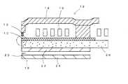
- 1is a cross-sectional view showing a configuration of a perpendicular magnetic recording type thin film magnetic head. It is explanatory drawing of the state which formed the recessed part on the inorganic insulating layer using the mask by a resist. It is explanatory drawing of the state which formed the plating seed layer in the required part of a recessed part. It is explanatory drawing which shows the state which the plating film of the 1st layer extended
- FIG. 1is a cross-sectional view showing a configuration of a perpendicular magnetic recording type thin film magnetic head.
- This thin film magnetic headincludes a main magnetic pole 10, a trailing shield 13, a return yoke 14 and a recording coil 16 as a perpendicular magnetic recording head 12, and an MR element 20, an upper shield 22 and a lower shield 24 as a reproducing head 18.
- An inorganic insulating layer 26 made of alumina or the likeis provided between the upper shield 22 and the main magnetic pole 10, and between the main magnetic pole 10 and the coil 16, between the coil 16 and the return yoke 14, and between the MR element 20 and the upper shield.
- An inorganic insulating layer made of alumina or the likeis also provided between 22 and the lower shield 24. Each of these layers can be formed by a known thin film technique.
- the present embodimentis characterized by the configuration of the main magnetic pole 10 described below and a method for manufacturing the same. 2 to 6 are explanatory views showing the manufacturing process of the main magnetic pole 10.
- the main magnetic pole 10is formed on the inorganic insulating layer 26 described above.
- An inorganic insulating layer 26 made of alumina or the likeis formed on the upper shield layer 22 (FIG. 1) by sputtering or the like.
- the inorganic insulating layeris not limited to alumina, and may be an inorganic insulating layer such as SiC, AlN, or TiC.
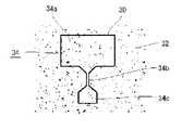
- grooves (recesses) for the damascene methodare formed on the inorganic insulating layer 26 by a known method. That is, the resist pattern 32 is formed on the inorganic insulating layer 26 except for the range of the solid line 30 shown in FIG. Using this resist pattern 32 as a mask, known RIE (Reactive Ion Etching) is performed to form a recess 34 in a portion surrounded by a solid line 30.
- RIEReactive Ion Etching
- the concave portion 34includes a core concave portion 34a that is a portion that forms the core portion of the main magnetic pole 10, a tip magnetic pole concave portion 34b that is a portion that forms the tip magnetic pole portion on the air bearing surface side of the main magnetic pole 10, and the tip It consists of a dummy recess 34c that is further on the tip side than the magnetic pole recess 34b.
- the dummy concave portion 34cis a portion that is removed by polishing in a later step and is not necessarily provided. However, the dummy recess 34c is preferably provided in order to improve the flow of the plating solution in the plating step described later. As shown in FIGS.
- the tip magnetic pole recess 34bis formed in an inverted triangular cross section or an inverted trapezoidal cross section.
- the core recess 34a and the dummy recess 34ccommunicate with the tip magnetic pole recess 34b and are formed wider than these.
- the peripheral wall portions of the core concave portion 34a and the dummy concave portion 34care inclined walls inclined at substantially the same angle as the inclined wall of the tip magnetic pole concave portion 34b.
- the plating seed layer 34is formed by sputtering a magnetic material having a relatively low saturation magnetic flux density such as NiFe.
- a resist mask(not shown) having only the core recess 34a and the dummy recess 34c opened is formed, and the core recess 34a
- a plating seed layer 36is formed in the dummy recess 34c and on the resist mask, and the plating seed layer 36 formed on the resist mask on the tip magnetic pole recess 34b is removed together with the resist mask (so-called lift-up method). It can be carried out.
- a plating seed layer 36(not shown) is formed in the entire recess 34, and the plating seed layer 34 formed in the tip magnetic pole recess 34b is removed by ion milling, so that the inside of the core recess 34a and a dummy are formed.
- the plating seed layer 36can be formed only in the recess 34c. In this manner, with the plating seed layer 36 formed in the core recess 34a and the dummy recess 34c, electrolytic plating is performed by a known method using the plating seed layer 36 as a conductive layer, and multilayer plating is performed in the recess 34. .
- the bottom surfaces in the core recesses 34a and the dummy recesses 34care flat surfaces, they are formed as parallel multilayer plating films in these recesses. Then, the plating solution flows into the tip magnetic pole recess 34b through the core recess 34a and the dummy recess 34c, and each plating film formed in the core recess 34a and the dummy recess 34c is formed in the tip magnetic pole recess.
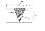
- the multilayer plating films 37 and 38 parallel to the trailing shield 13are formed in the tip magnetic pole recess 34b (FIG. 6). 4 and 5 show a state in which the first plating film 37 is formed. As shown in FIG.
- a plating film 37(and a plating film 38) extends from both the core recess 34a and the dummy recess 34c into the tip magnetic pole recess 34b. ) You don't have to. That is, the tip magnetic pole portion 40 (FIG. 6) formed in the tip magnetic pole recess 34b is polished when the air bearing surface is formed and formed to a required length, and only that length is secured. This is because a plating film extending from the core recess 34a is sufficient.
- the inorganic insulating layer 26 side(leading side) is made of a magnetic material having a relatively low saturation magnetic flux density, for example, an NiFe alloy plating layer 37, and the opposite trailing side is higher than the alloy plating layer 37.
- an FeCo alloy plating layer 38made of a magnetic material having a saturation magnetic flux density is formed. Since the plating conditions for these alloy platings may be known conditions, description thereof is omitted.
- the tip pole portion 40 formed in the tip pole recess 34b of the main pole 10can be formed on the multilayer plating layers 37 and 38 parallel to the trailing shield 13, and the trailing side is highly saturated. The recording characteristics can be improved by disposing the plating layer 38 having a magnetic flux density.
- the multilayer plating filmhas been described as an example of two layers. However, three or more multilayer plating layers may be used. In the present invention, it is defined as a multilayer including the case of two layers. Moreover, after forming the multilayer plating layers 37 and 38 in the recessed part 34, it is good to perform CMP process and to planarize the upper surface of a multilayer plating layer.
- the plating seed layer 36may be formed even on the inorganic insulating layer 26. This excess plating seed layer 36 can be removed by a CMP process.
- a large number of thin film magnetic headsare formed in a matrix on a wafer, then each row is cut out to form a row bar, and the surface of each row bar that becomes the air bearing surface side of the magnetic head is polished by a required amount.
- the MR height and the length of the tip magnetic pole portion of the main magnetic pole 10are adjusted and finally cut into individual pieces to complete the thin film magnetic head. Since this series of steps is publicly known, a description thereof will be omitted.
Landscapes
- Engineering & Computer Science (AREA)
- Manufacturing & Machinery (AREA)
- Magnetic Heads (AREA)
Abstract
Description
Translated fromJapanese本発明は、磁気記録ディスク装置などの記録に用いられる垂直磁気記録ヘッドおよび垂直磁気記録ヘッドの主磁極の製造方法に関する。The present invention relates to a perpendicular magnetic recording head used for recording in a magnetic recording disk device or the like and a method of manufacturing a main magnetic pole of the perpendicular magnetic recording head.
垂直磁気記録ヘッドの主磁極は、側面が傾斜面に形成され、断面形状が逆三角形状もしくは逆台形状となっている。このように、主磁極の断面形状を逆三角形状もしくは逆台形状に形成しているのは、磁気ヘッドがトラックを移動する際に生じるアジマス角度によってサイドイレーズをが生じないようにするためで、主磁極の側面の傾斜角度は80°~85°程度に設定されている。なお、主磁極の上面(トレーリング側の面)が最終的に情報を記録する部位で、精度よく情報を記録できるようにするためには、主磁極の上面のエッジが鋭角に形成されている必要がある。
主磁極を上記のように断面逆三角形状もしくは逆台形状に形成する方法の一つに、いわゆるダマシン法がある。
このダマシン法は、アルミナ膜等の無機絶縁層に主磁極形状の溝(凹部)を形成し、この溝内にめっきシード層を成膜し、このめっきシード層を通電層としてめっきを施し、溝内にめっき皮膜を盛り上げて主磁極を形成するものである。
One of the methods for forming the main magnetic pole in an inverted triangular shape or inverted trapezoidal shape as described above is a so-called damascene method.
In this damascene method, a main pole-shaped groove (concave portion) is formed in an inorganic insulating layer such as an alumina film, a plating seed layer is formed in the groove, plating is performed using the plating seed layer as a conductive layer, and the groove is formed. The main magnetic pole is formed by raising the plating film inside.
本願は上記課題を解決すべくなされたものであり、その目的とするところは、ダマシン法による平行な多層構造の主磁極を有し、記録特性に優れる垂直磁気記録ヘッドおよびこの垂直磁気記録ヘッドの主磁極の製造方法を提供するにある。
すなわち、本発明に係る垂直磁気記録ヘッドは、無機絶縁層上に形成された凹部内にめっきで形成された主磁極と、通電することで前記主磁極に磁束を生じさせるコイルと、リターンヨークとを有する垂直磁気記録ヘッドにおいて、前記凹部は、トレーリング側に幅広となる断面逆三角形状もしくは逆台形状の凹部をなす先端磁極用凹部と、該先端磁極用凹部に連通し、先端磁極用凹部よりも幅広のコア用凹部とに形成され、該凹部の前記コア用凹部にめっきシード層が形成され、前記主磁極は、前記めっきシード層を通電層として前記コア用凹部内に形成された多層のめっき層からなるコア部と、前記コア用凹部内にめっきによって形成される各めっき層がめっきシード層の形成されていない前記先端磁極用凹部内に伸長して形成された多層のめっき層からなる先端磁極部とから形成されていることを特徴とする。
前記主磁極は、トレーリング側となるめっき層が、前記無機絶縁層側のめっき層よりも高い飽和磁束密度を有する磁性層に形成するとよい。
また、本発明は、無機絶縁層上に形成された凹部内にめっきで形成された主磁極と、通電することで前記主磁極に磁束を生じさせるコイルと、リターンヨークとを有する垂直磁気記録ヘッドの主磁極の製造方法において、前記無機絶縁層を形成する工程と、該無機絶縁層上に形成したマスクによりマスクして無機絶縁層をエッチングして、トレーリング側に幅広となる断面逆三角形状もしくは逆台形状をなす先端磁極用凹部と、該先端磁極用凹部に連通し、先端磁極用凹部よりも幅広となるコア用凹部とを含む凹部を形成する工程と、前記マスクを除去する工程と、前記無機絶縁層に形成された凹部のうち、前記コア用凹部にのみめっきシード層を形成する工程と、該めっきシード層を通電層として前記コア用凹部内にめっきを施して多層のめっき層からなる主磁極のコア部を形成すると共に、前記コア用凹部内にめっきによって形成される各めっき層をめっきシード層の形成されていない前記先端磁極用凹部内に伸長させることによって前記先端磁極用凹部内に多層のめっき層からなる主磁極の先端磁極部を形成するめっき工程とを具備することを特徴とする。
前記凹部内に形成された多層のめっき層をCMP工程で平坦化するようにするとよい。
また、前記コア用凹部のみを開口したレジストマスクを形成し、コア用凹部内およびレジストマスク上にめっきシード層を形成し、前記先端磁極用凹部のレジストマスク上に形成されためっきシード層をレジストマスクと共に除去して、前記無機絶縁層に形成された凹部のうち、前記コア用凹部にのみめっきシード層を形成することを特徴とする。
あるいは、前記凹部全体にめっきシード層を形成し、前記先端磁極用凹部内に形成されためっきシード層をイオンミリングで除去して、前記無機絶縁層に形成された凹部のうち、前記コア用凹部にのみめっきシード層を形成することができる。The present application has been made to solve the above-described problems, and the object of the present application is a perpendicular magnetic recording head having a parallel multi-layered main magnetic pole by the damascene method and excellent in recording characteristics, and the perpendicular magnetic recording head. It is in providing the manufacturing method of a main pole.
That is, a perpendicular magnetic recording head according to the present invention includes a main magnetic pole formed by plating in a recess formed on an inorganic insulating layer, a coil that generates a magnetic flux in the main magnetic pole when energized, a return yoke, In the perpendicular magnetic recording head, the recessed portion communicates with the recessed portion for the tip magnetic pole that forms a recessed portion having an inverted triangular or inverted trapezoidal cross section that is wide on the trailing side, and the recessed portion for the distal magnetic pole. And a plating seed layer is formed in the concave portion for the core of the concave portion, and the main magnetic pole is formed in the concave portion for the core with the plating seed layer as an energization layer. A core portion made of a plurality of plating layers and a plurality of plating layers formed by plating in the core recesses are formed by extending into the tip pole recesses where no plating seed layer is formed. Characterized in that it is formed from the consisting of the plating layer tip magnetic pole portion.
The main magnetic pole may be formed in a magnetic layer in which a plating layer on the trailing side has a higher saturation magnetic flux density than a plating layer on the inorganic insulating layer side.
The present invention also provides a perpendicular magnetic recording head having a main magnetic pole formed by plating in a recess formed on an inorganic insulating layer, a coil for generating a magnetic flux in the main magnetic pole when energized, and a return yoke. In the method of manufacturing the main magnetic pole, the step of forming the inorganic insulating layer and the cross-sectional inverted triangle shape that is widened on the trailing side by etching the inorganic insulating layer by masking with a mask formed on the inorganic insulating layer Alternatively, a step of forming a concave portion including a concave portion for a tip magnetic pole having an inverted trapezoidal shape and a concave portion for a core that communicates with the concave portion for the leading magnetic pole and is wider than the concave portion for the leading pole, and a step of removing the mask A step of forming a plating seed layer only in the core recess among the recesses formed in the inorganic insulating layer, and plating in the core recess using the plating seed layer as an energization layer. Forming a core portion of the main magnetic pole made of a plating layer, and extending each plating layer formed by plating in the core concave portion into the tip magnetic pole concave portion in which no plating seed layer is formed. And a plating step of forming a tip magnetic pole portion of a main magnetic pole made of a multi-layered plating layer in the concave portion for the tip magnetic pole.
The multilayer plating layer formed in the recess may be planarized by a CMP process.
In addition, a resist mask having an opening only in the core recess is formed, a plating seed layer is formed in the core recess and on the resist mask, and the plating seed layer formed on the resist mask in the tip magnetic pole recess is resisted. A plating seed layer is formed only in the concave portion for the core among the concave portions formed in the inorganic insulating layer by being removed together with the mask.
Alternatively, a plating seed layer is formed over the entire recess, the plating seed layer formed in the tip magnetic pole recess is removed by ion milling, and the core recess among the recesses formed in the inorganic insulating layer Only a plating seed layer can be formed.
発明の効果
本発明によれば、ダマシン法による平行な多層構造のであって狭コア幅な主磁極を有し、記録特性に優れる垂直磁気記録ヘッドを提供できる。また、本発明の垂直磁気記録ヘッドの主磁極の製造方法によれば、ダマシン法により、狭コア幅で、かつ平行な多層構造の主磁極を有する主磁極を製造することができる。According to the present invention, it is possible to provide a perpendicular magnetic recording head having a parallel magnetic multi-layer structure by a damascene method, a main pole having a narrow core width, and excellent recording characteristics. Further, according to the method of manufacturing the main magnetic pole of the perpendicular magnetic recording head of the present invention, a main magnetic pole having a narrow core width and a parallel multi-layered main magnetic pole can be manufactured by the damascene method.
以下本発明の好適な実施の形態を添付図面に基づいて詳細に説明する。
図1は、垂直磁気記録型の薄膜磁気ヘッドの構成を示す断面図である。
この薄膜磁気ヘッドは、垂直磁気記録ヘッド12として主磁極10、トレーリングシールド13、リターンヨーク14および記録用コイル16を備え、再生ヘッド18として、MR素子20、上部シールド22および下部シールド24を備える。
上部シールド22と主磁極10との間にはアルミナ等からなる無機絶縁層26が設けられ、主磁極10とコイル16との間、コイル16とリターンヨーク14との間、MR素子20と上部シールド22および下部シールド24との間もアルミナ等からなる無機絶縁層が設けられている。
これら各層は公知の薄膜技術によって形成することができる。
本実施の形態で特徴とするのは、以下に述べる主磁極10の構成およびその製造方法である。
図2~図6は、主磁極10の製造工程を示す説明図である。
主磁極10は、上記の無機絶縁層26上に形成される。
上部シールド層22(図1)の上にスパッタリング等によってアルミナ等からなる無機絶縁層26を形成する。無機絶縁層はアルミナに限定されず、SiC、AlN、TiCなどの無機絶縁層とすることもできる。
次にこの無機絶縁層26上に公知の方法によって、ダマシン法用の溝(凹部)を形成する。すなわち、無機絶縁層26に、図2に示す実線30の範囲を除いてレジストパターン32を形成する。このレジストパターン32をマスクとして公知のRIE(反応性イオンエッチング)を行い、実線30で囲まれた部位に凹部34を形成する。
この凹部34は、主磁極10のコア部を形成する部位であるコア用凹部34aと、主磁極10の浮上面側となる先端磁極部を形成する部位である先端磁極用凹部34bと、この先端磁極用凹部34bよりもさらに先端側となるダミー凹部34cとからなる。ダミー凹部34cは、後工程で研磨により除去される部位であり、必ずしも設ける必要がないが、後記するめっき工程でのめっき液の通流をよくするためには設けた方がよい。
先端磁極用凹部34bは、図5、図6に示すように断面逆三角形状か、もしくは断面逆台形状に形成する。コア用凹部34aとダミー凹部34cとは、先端磁極用凹部34bと連通し、かつこれらよりも幅広に形成される。なお、コア用凹部34aとダミー凹部34cの周壁部は、先端磁極用凹部34bの傾斜壁とほぼ同角度で傾斜する傾斜壁となる。
凹部34を形成した後、レジストパターン32を除去する。
次いで、図3に示すように、コア用凹部34aとダミー凹部34c内にめっきシード層36を形成する。このめっきシード層34は、NiFe等の比較的低い飽和磁束密度の磁性材料をスパッタリングして形成する。
コア用凹部34a内とダミー凹部34c内にめっきシード層36を形成するには、コア用凹部34aおよびダミー凹部34cのみを開口したレジストマスク(図示せず)を形成し、コア用凹部34a内、ダミー凹部34c内およびレジストマスク上にめっきシード層36を形成し、先端磁極用凹部34b上のレジストマスク上に形成されためっきシード層36をレジストマスクと共に除去する(いわゆるリフトアップ法)ようにして行うことができる。
あるいは、凹部34全体にめっきシード層36を形成し(図示せず)、先端磁極用凹部34b内に形成されためっきシード層34をイオンミリングで除去するようにして、コア用凹部34a内とダミー凹部34c内のみにめっきシード層36を形成するようにすることができる。
このように、コア用凹部34a内とダミー凹部34c内にめっきシード層36を形成した状態で、めっきシード層36を通電層として公知の方法によって電解めっきを行い、凹部34内に多層めっきを行う。
この場合、コア用凹部34a内とダミー凹部34c内の底面は平坦面であるから、これら凹部内に平行な多層めっき皮膜として形成される。
そして、コア用凹部34aとダミー凹部34cとを通じて、先端磁極用凹部34b内にもめっき液が通流し、コア用凹部34a内とダミー凹部34c内とに形成される各めっき皮膜が先端磁極用凹部34b内に伸長し、これにより、先端磁極用凹部34b内にもトレーリングシールド13と平行な多層めっき皮膜37、38が形成される(図6)。なお、図4および図5は、1層目のめっき皮膜37を形成した状態を示す。
先端磁極用凹部34b内には、図4に示すように、コア用凹部34a内とダミー凹部34c内の双方からめっき皮膜37(およびめっき皮膜38)が伸長してくるが、これらは合体(連続)しなくともよい。すなわち、先端磁極用凹部34b内に形成される先端磁極部40(図6)は、浮上面を形成する際に研磨され、所要長さに形成されるのであって、その長さだけ確保されればよく、コア用凹部34aから伸長するめっき皮膜だけで十分足りるからである。
多層めっき皮膜は、無機絶縁層26側(リーディング側)は比較的低い飽和磁束密度の磁性材料からなる、例えばNiFeの合金めっき層37とし、その反対のトレーリング側は合金めっき層37よりも高い飽和磁束密度を有する磁性材料からなる、例えばFeCoの合金めっき層38に形成する。これら合金めっきのめっき条件は公知の条件でよいので説明を省略する。このように、主磁極10の、先端磁極用凹部34b内に形成される先端磁極部40を、トレーリングシールド13と平行な多層めっき層37、38に形成できること、また、トレーリング側に高い飽和磁束密度を有するめっき層38を配置することによって記録特性を向上させることができる。
なお、上記では、多層めっき皮膜として2層の例で説明したが、3層以上の多層めっき層としてもよい。本発明では2層の場合も含めて多層と定義する。
また、凹部34内に多層めっき層37、38を形成した後、CMP処理を施して、多層めっき層の上面を平坦化するとよい。前記のめっきシード層36は、無機絶縁層26上にまで形成してもよい。この余分なめっきシード層36はCMP処理によって除去できる。
薄膜磁気ヘッドはウェーハ上にマトリクス状に多数作りこまれた後、各列毎切り出されてローバーに形成され、切り出された各ローバーの、磁気ヘッドの浮上面側となる面が所要量研磨されて、MRハイトや、主磁極10の先端磁極部の長さが調整され、最終的に個片に切断されて薄膜磁気ヘッドに完成される。この一連の工程は公知であるので説明を省略する。Preferred embodiments of the present invention will be described below in detail with reference to the accompanying drawings.
FIG. 1 is a cross-sectional view showing a configuration of a perpendicular magnetic recording type thin film magnetic head.
This thin film magnetic head includes a main
An
Each of these layers can be formed by a known thin film technique.
The present embodiment is characterized by the configuration of the main
2 to 6 are explanatory views showing the manufacturing process of the main
The main
An
Next, grooves (recesses) for the damascene method are formed on the
The
As shown in FIGS. 5 and 6, the tip
After forming the
Next, as shown in FIG. 3, a plating
In order to form the
Alternatively, a plating seed layer 36 (not shown) is formed in the
In this manner, with the
In this case, since the bottom surfaces in the core recesses 34a and the dummy recesses 34c are flat surfaces, they are formed as parallel multilayer plating films in these recesses.
Then, the plating solution flows into the tip
As shown in FIG. 4, a plating film 37 (and a plating film 38) extends from both the
In the multilayer plating film, the inorganic insulating
In the above description, the multilayer plating film has been described as an example of two layers. However, three or more multilayer plating layers may be used. In the present invention, it is defined as a multilayer including the case of two layers.
Moreover, after forming the multilayer plating layers 37 and 38 in the recessed
A large number of thin film magnetic heads are formed in a matrix on a wafer, then each row is cut out to form a row bar, and the surface of each row bar that becomes the air bearing surface side of the magnetic head is polished by a required amount. The MR height and the length of the tip magnetic pole portion of the main
Claims (7)
Translated fromJapanese前記凹部は、トレーリング側に幅広となる断面逆三角形状もしくは逆台形状の凹部をなす先端磁極用凹部と、該先端磁極用凹部に連通し、先端磁極用凹部よりも幅広のコア用凹部とに形成され、
該凹部の前記コア用凹部にめっきシード層が形成され、
前記主磁極は、
前記めっきシード層を通電層として前記コア用凹部内に形成された多層のめっき層からなるコア部と、前記コア用凹部内にめっきによって形成される各めっき層がめっきシード層の形成されていない前記先端磁極用凹部内に伸長して形成された多層のめっき層からなる先端磁極部とから形成されていることを特徴とする垂直磁気記録ヘッド。In a perpendicular magnetic recording head having a main magnetic pole formed by plating in a recess formed on an inorganic insulating layer, a coil that generates a magnetic flux in the main magnetic pole when energized, and a return yoke.
The concave portion includes a concave portion for a tip magnetic pole that forms a concave portion having an inverted triangular or inverted trapezoidal shape that is wide on the trailing side, and a concave portion for a core that communicates with the concave portion for the leading pole and is wider than the concave portion for the leading pole. Formed into
A plating seed layer is formed in the recess for the core of the recess,
The main pole is
The plating seed layer is not formed in the core part composed of a multi-layered plating layer formed in the concave part for the core using the plating seed layer as a conductive layer, and each plating layer formed by plating in the concave part for the core A perpendicular magnetic recording head, comprising: a tip magnetic pole portion formed of a multi-layered plating layer formed extending in the tip magnetic pole recess.
前記無機絶縁層を形成する工程と、
該無機絶縁層上に形成したマスクによりマスクして無機絶縁層をエッチングして、トレーリング側に幅広となる断面逆三角形状もしくは逆台形状をなす先端磁極用凹部と、該先端磁極用凹部に連通し、先端磁極用凹部よりも幅広となるコア用凹部とを含む凹部を形成する工程と、
前記マスクを除去する工程と、
前記無機絶縁層に形成された凹部のうち、前記コア用凹部にのみめっきシード層を形成する工程と、
該めっきシード層を通電層として前記コア用凹部内にめっきを施して多層のめっき層からなる主磁極のコア部を形成すると共に、前記コア用凹部内にめっきによって形成される各めっき層をめっきシード層の形成されていない前記先端磁極用凹部内に伸長させることによって前記先端磁極用凹部内に多層のめっき層からなる主磁極の先端磁極部を形成するめっき工程とを具備することを特徴とする垂直磁気記録ヘッドの主磁極の製造方法。Method for manufacturing main pole of perpendicular magnetic recording head having main pole formed by plating in recess formed on inorganic insulating layer, coil for generating magnetic flux in said main pole by energization, and return yoke In
Forming the inorganic insulating layer;
Etching the inorganic insulating layer with a mask formed on the inorganic insulating layer to etch the tip magnetic pole recess having an inverted triangular shape or a trapezoidal shape having a wide cross section on the trailing side, and the tip magnetic pole recess A step of forming a recess including a core recess that is wider than the recess for the tip magnetic pole;
Removing the mask;
Of the recesses formed in the inorganic insulating layer, a step of forming a plating seed layer only in the core recesses;
Using the plating seed layer as an energization layer, plating is performed in the core recess to form the core portion of the main pole composed of a multi-layer plating layer, and each plating layer formed by plating is plated in the core recess A plating step of forming a tip magnetic pole portion of a main pole made of a multi-layer plating layer in the tip magnetic pole recess by extending into the tip magnetic pole recess in which no seed layer is formed. A method of manufacturing a main magnetic pole of a perpendicular magnetic recording head.
The plating layer on the trailing side of the main magnetic pole is formed of a magnetic layer having a higher saturation magnetic flux density than the plating layer on the inorganic insulating layer side. Of manufacturing the main pole of the perpendicular magnetic recording head.
Priority Applications (1)
| Application Number | Priority Date | Filing Date | Title |
|---|---|---|---|
| PCT/JP2008/060278WO2009147733A1 (en) | 2008-06-04 | 2008-06-04 | Perpendicular magnetic recording head and manufacturing method of main pole of perpendicular magnetic recording head |
Applications Claiming Priority (1)
| Application Number | Priority Date | Filing Date | Title |
|---|---|---|---|
| PCT/JP2008/060278WO2009147733A1 (en) | 2008-06-04 | 2008-06-04 | Perpendicular magnetic recording head and manufacturing method of main pole of perpendicular magnetic recording head |
Publications (1)
| Publication Number | Publication Date |
|---|---|
| WO2009147733A1true WO2009147733A1 (en) | 2009-12-10 |
Family
ID=41397825
Family Applications (1)
| Application Number | Title | Priority Date | Filing Date |
|---|---|---|---|
| PCT/JP2008/060278CeasedWO2009147733A1 (en) | 2008-06-04 | 2008-06-04 | Perpendicular magnetic recording head and manufacturing method of main pole of perpendicular magnetic recording head |
Country Status (1)
| Country | Link |
|---|---|
| WO (1) | WO2009147733A1 (en) |
Citations (3)
| Publication number | Priority date | Publication date | Assignee | Title |
|---|---|---|---|---|
| JP2002230716A (en)* | 2001-02-06 | 2002-08-16 | Alps Electric Co Ltd | Thin-film magnetic head, and its manufacturing method |
| JP2006139898A (en)* | 2004-11-12 | 2006-06-01 | Headway Technologies Inc | Thin-film magnetic head structure and method for manufacturing the same, and thin-film magnetic head |
| JP2007242132A (en)* | 2006-03-08 | 2007-09-20 | Fujitsu Ltd | Perpendicular magnetic head |
- 2008
- 2008-06-04WOPCT/JP2008/060278patent/WO2009147733A1/ennot_activeCeased
Patent Citations (3)
| Publication number | Priority date | Publication date | Assignee | Title |
|---|---|---|---|---|
| JP2002230716A (en)* | 2001-02-06 | 2002-08-16 | Alps Electric Co Ltd | Thin-film magnetic head, and its manufacturing method |
| JP2006139898A (en)* | 2004-11-12 | 2006-06-01 | Headway Technologies Inc | Thin-film magnetic head structure and method for manufacturing the same, and thin-film magnetic head |
| JP2007242132A (en)* | 2006-03-08 | 2007-09-20 | Fujitsu Ltd | Perpendicular magnetic head |
Similar Documents
| Publication | Publication Date | Title |
|---|---|---|
| US10014021B1 (en) | Perpendicular magnetic recording (PMR) write head with patterned leading shield | |
| US8498079B1 (en) | Superior performance head design with minimized ATE and WATE | |
| JP5674295B2 (en) | Perpendicular magnetic recording head and manufacturing method thereof | |
| US9361912B1 (en) | High moment side shield design for area density improvement of perpendicular magnetic recording (PMR) writer | |
| US7248431B1 (en) | Method of fabricating a perpendicular recording write head having a gap with two portions | |
| US7181829B2 (en) | Method of manufacturing a perpendicular magnetic recording head | |
| US7742258B2 (en) | Magnetic transducer with milling mask | |
| US20190206428A1 (en) | Method of Forming a Perpendicular Magnetic Recording (PMR) Write Head with Patterned Leading Edge Taper | |
| JP4803949B2 (en) | Method for manufacturing composite thin film magnetic head | |
| US9697855B1 (en) | Perpendicular magnetic recording (PMR) write head with multiple layer trailing shield | |
| JP2000105906A (en) | Production of thin film magnetic head | |
| US20060152852A1 (en) | Thin film magnetic head having solenoidal coil and method of manufacturing the same | |
| US7151647B2 (en) | Thin film magnetic head and manufacturing method for creating high surface recording density and including a second yoke portion having two layers of which one is etched to form a narrow portion and a sloped flare portion | |
| JP2007004958A (en) | Thin-film magnetic head for perpendicular magnetic recording | |
| US7124498B2 (en) | Method for manufacturing magnetic head | |
| US6882502B2 (en) | Thin-film magnetic head with narrowed track width and method for making same | |
| US7228619B2 (en) | Method of manufacturing a magnetic head with common seed layer for coil and pedestal | |
| JP2007242133A (en) | Perpendicular magnetic head | |
| US7626785B2 (en) | Thin film magnetic head, method of manufacturing the same, and magnetic recording apparatus | |
| JP3950807B2 (en) | Thin film magnetic head | |
| JP3499458B2 (en) | Thin film magnetic head, method of manufacturing the same, and method of forming thin film coil | |
| JP4846773B2 (en) | Thin film magnetic head | |
| US6940689B2 (en) | Thin-film magnetic head comprising a first pole layer having multiple layers including a second layer and a thin-film coil having a portion disposed between the second layer and a coupling portion and method of manufacturing the thin-film magnetic head | |
| JPH10302219A (en) | Thin film magnetic head and manufacturing method | |
| WO2009147733A1 (en) | Perpendicular magnetic recording head and manufacturing method of main pole of perpendicular magnetic recording head |
Legal Events
| Date | Code | Title | Description |
|---|---|---|---|
| 121 | Ep: the epo has been informed by wipo that ep was designated in this application | Ref document number:08765091 Country of ref document:EP Kind code of ref document:A1 | |
| NENP | Non-entry into the national phase | Ref country code:DE | |
| 122 | Ep: pct application non-entry in european phase | Ref document number:08765091 Country of ref document:EP Kind code of ref document:A1 | |
| NENP | Non-entry into the national phase | Ref country code:JP |