WO2009131316A2 - Raindrop sensor - Google Patents
Raindrop sensorDownload PDFInfo
- Publication number
- WO2009131316A2 WO2009131316A2PCT/KR2009/001739KR2009001739WWO2009131316A2WO 2009131316 A2WO2009131316 A2WO 2009131316A2KR 2009001739 WKR2009001739 WKR 2009001739WWO 2009131316 A2WO2009131316 A2WO 2009131316A2
- Authority
- WO
- WIPO (PCT)
- Prior art keywords
- light
- receiving element
- light source
- signal
- light receiving
- Prior art date
Links
- 230000003287optical effectEffects0.000claimsabstractdescription29
- 238000001514detection methodMethods0.000claimsdescription67
- 239000011521glassSubstances0.000claimsdescription53
- 238000000034methodMethods0.000claimsdescription21
- 239000000758substrateSubstances0.000claimsdescription21
- 230000010355oscillationEffects0.000claimsdescription13
- XLYOFNOQVPJJNP-UHFFFAOYSA-NwaterSubstancesOXLYOFNOQVPJJNP-UHFFFAOYSA-N0.000claimsdescription5
- 230000001678irradiating effectEffects0.000claimsdescription3
- 230000026683transductionEffects0.000abstract1
- 238000010361transductionMethods0.000abstract1
- 230000000694effectsEffects0.000description7
- 238000010586diagramMethods0.000description6
- 238000006243chemical reactionMethods0.000description3
- 230000007257malfunctionEffects0.000description3
- 230000001154acute effectEffects0.000description2
- 230000007423decreaseEffects0.000description2
- 238000001914filtrationMethods0.000description2
- 230000001795light effectEffects0.000description2
- 238000007796conventional methodMethods0.000description1
- 239000000284extractSubstances0.000description1
- 238000009434installationMethods0.000description1
Images


Classifications
- B—PERFORMING OPERATIONS; TRANSPORTING
- B60—VEHICLES IN GENERAL
- B60S—SERVICING, CLEANING, REPAIRING, SUPPORTING, LIFTING, OR MANOEUVRING OF VEHICLES, NOT OTHERWISE PROVIDED FOR
- B60S1/00—Cleaning of vehicles
- B60S1/02—Cleaning windscreens, windows or optical devices
- B60S1/04—Wipers or the like, e.g. scrapers
- B60S1/06—Wipers or the like, e.g. scrapers characterised by the drive
- B60S1/08—Wipers or the like, e.g. scrapers characterised by the drive electrically driven
- B60S1/0818—Wipers or the like, e.g. scrapers characterised by the drive electrically driven including control systems responsive to external conditions, e.g. by detection of moisture, dirt or the like
- B60S1/0822—Wipers or the like, e.g. scrapers characterised by the drive electrically driven including control systems responsive to external conditions, e.g. by detection of moisture, dirt or the like characterized by the arrangement or type of detection means
- B60S1/0833—Optical rain sensor
- B60S1/0837—Optical rain sensor with a particular arrangement of the optical elements
- G—PHYSICS
- G01—MEASURING; TESTING
- G01N—INVESTIGATING OR ANALYSING MATERIALS BY DETERMINING THEIR CHEMICAL OR PHYSICAL PROPERTIES
- G01N21/00—Investigating or analysing materials by the use of optical means, i.e. using sub-millimetre waves, infrared, visible or ultraviolet light
- G01N21/17—Systems in which incident light is modified in accordance with the properties of the material investigated
- G01N21/25—Colour; Spectral properties, i.e. comparison of effect of material on the light at two or more different wavelengths or wavelength bands
- G01N21/31—Investigating relative effect of material at wavelengths characteristic of specific elements or molecules, e.g. atomic absorption spectrometry
- G01N21/35—Investigating relative effect of material at wavelengths characteristic of specific elements or molecules, e.g. atomic absorption spectrometry using infrared light
- G—PHYSICS
- G01—MEASURING; TESTING
- G01N—INVESTIGATING OR ANALYSING MATERIALS BY DETERMINING THEIR CHEMICAL OR PHYSICAL PROPERTIES
- G01N21/00—Investigating or analysing materials by the use of optical means, i.e. using sub-millimetre waves, infrared, visible or ultraviolet light
- G01N21/17—Systems in which incident light is modified in accordance with the properties of the material investigated
- G01N21/47—Scattering, i.e. diffuse reflection
- G01N21/4738—Diffuse reflection, e.g. also for testing fluids, fibrous materials
- G—PHYSICS
- G01—MEASURING; TESTING
- G01N—INVESTIGATING OR ANALYSING MATERIALS BY DETERMINING THEIR CHEMICAL OR PHYSICAL PROPERTIES
- G01N21/00—Investigating or analysing materials by the use of optical means, i.e. using sub-millimetre waves, infrared, visible or ultraviolet light
- G01N21/17—Systems in which incident light is modified in accordance with the properties of the material investigated
- G01N21/25—Colour; Spectral properties, i.e. comparison of effect of material on the light at two or more different wavelengths or wavelength bands
- G01N21/31—Investigating relative effect of material at wavelengths characteristic of specific elements or molecules, e.g. atomic absorption spectrometry
- G01N21/35—Investigating relative effect of material at wavelengths characteristic of specific elements or molecules, e.g. atomic absorption spectrometry using infrared light
- G01N21/3554—Investigating relative effect of material at wavelengths characteristic of specific elements or molecules, e.g. atomic absorption spectrometry using infrared light for determining moisture content
- G—PHYSICS
- G01—MEASURING; TESTING
- G01N—INVESTIGATING OR ANALYSING MATERIALS BY DETERMINING THEIR CHEMICAL OR PHYSICAL PROPERTIES
- G01N21/00—Investigating or analysing materials by the use of optical means, i.e. using sub-millimetre waves, infrared, visible or ultraviolet light
- G01N21/17—Systems in which incident light is modified in accordance with the properties of the material investigated
- G01N21/55—Specular reflectivity
- G—PHYSICS
- G01—MEASURING; TESTING
- G01N—INVESTIGATING OR ANALYSING MATERIALS BY DETERMINING THEIR CHEMICAL OR PHYSICAL PROPERTIES
- G01N2201/00—Features of devices classified in G01N21/00
- G01N2201/06—Illumination; Optics
- G01N2201/062—LED's
- G01N2201/0625—Modulated LED
Definitions
- the present inventionrelates to a raindrop detection sensor to recognize the amount of raindrops by receiving the amount of light reflected from the raindrops in the direction of the light source when the raindrops sensor is attached to the windshield of the vehicle attached to the windshield attached to the sensor.
- the present inventionrelates to a raindrop detection sensor that is not affected by the ambient light other than the optical signal reflected from the raindrops to increase the detection efficiency of the degree of rainfall.
- the raindrop detection sensorinjects the signal light into the windshield of the car, and when raindrops fall on the windshield, the waveguided light exits through the inside of the window to the outside, and the amount of light reaching the light receiving element installed on the opposite side is reduced to determine the degree of raindrop fall. If the raindrops fall on the glass window by inclining the signal light at an angle, the reflectance changes, and the amount of light reaching the light-receiving elements installed on the opposite side is changed to determine the degree of raindrop falling.
- the raindropsfell on the glass window by inclining the signal light at an angle, the reflectance changes, and the amount of light reaching the light-receiving elements installed on the opposite side is changed to determine the degree of raindrop falling.
- the first of these methodsrequires the optical coupler to be in close contact with the windshield of the car and to maintain the correct angle of incidence when the signal light used as the sensor is incident to be guided into the inside of the windshield of the car, making the optical system complicated and difficult to install. There was a downside.
- the second methodsince the light receiving device is installed on the opposite side of the light source used as the sensor, not only the reflection by raindrops but also the reflected light reflected from the front windshield surface of the vehicle is incident on the light receiving device, which lowers the signal-to-noise ratio.
- the light source and the light receiving element pairs used as sensorsare arranged in a row, a large number of light source and light receiving element pairs are needed to detect raindrops falling on a large area, which has a disadvantage in that the detection area per light source and light receiving element pairs is narrow.
- the raindrop detection method using the waveguide inside the front windshield of the vehicle according to the prior arthas a disadvantage in that the optical system is complicated and difficult to install, and the method of measuring the reflected light due to the raindrop by placing the light source and the light receiving device on the opposite side is a surface of the glass window.
- the signal-to-noise ratiowas degraded due to the reflection at, and the reflection type arrangement in which the light source and the light receiving element were arranged in a row had a narrow raindrop detection area.
- the windshieldis installed on the windshield of the vehicle to overcome the clock obstacle caused by rain in the rain, the wiper is intermittent speed control of the wiper according to the degree of falling rain.
- the speed control system of the wiperis adjusted in only a few steps, the driver cannot move the wiper at a desired speed according to the amount of rainwater.
- the first of these methodsrequires the optical coupler to be in close contact with the windshield of the car and to maintain the correct angle of incidence when the signal light used as the sensor is incident to be guided into the inside of the windshield of the car, making the optical system complicated and difficult to install. There was a downside.
- the second methodsince the light receiving device is installed on the opposite side of the light source used as the sensor, not only the reflection by raindrops but also the reflected light reflected from the surface of the front windshield of the vehicle is incident on the light receiving device, which lowers the signal-to-noise ratio.
- the light source and the light receiving element pairs used as sensorsare arranged in a row, a large number of light source and light receiving element pairs are needed to detect raindrops falling on a large area, which has a disadvantage in that the detection area per light source and light receiving element pairs is narrow.
- the product developed to improve the above disadvantagesstill has a large amount of reflection from the glass window of the vehicle body as well as the optical signal reflected from the raindrops, the signal-to-band ratio is lowered, the performance of raindrop detection efficiency is not as expected. .
- the optical signal obtained by the reciprocation of the wiperis also received, which is affected by the headlights of the vehicle on the opposite side, so that the efficiency is not better.
- the optical signal obtained by the reciprocation of the wiperis also received, which is affected by the headlights of the vehicle on the opposite side, so that the efficiency is not better.
- the optical signal obtained by the reciprocation of the wiperis also received, which is affected by the headlights of the vehicle on the opposite side, so that the efficiency is not better.
- the optical signal obtained by the reciprocation of the wiperis also received, which is affected by the headlights of the vehicle on the opposite side, so that the efficiency is not better.
- the present inventionwas developed to solve the above problems, the purpose of which is to detect raindrops over a larger area efficiently using a small number of light sources and light-receiving elements in a reflective raindrop detection method, at the same time It is simple to install and minimizes the influence of ambient light by using modulated signal light without being affected by the reflected light reflected from the windshield surface of the car, and implements effective raindrop detection method in terms of raindrop detection area.
- an object of the present inventionis to simplify the optical system, easy installation, light source for transmitting light to the glass window and the light receiving element for collecting light reflected from the raindrops on the surface of the glass window It is designed to prevent the signal-to-noise ratio from being lowered by being affected by the reflected light reflected from the front windshield surface of the vehicle instead of the reflection by raindrops, and not receiving the optical signal due to the round trip of the wiper. Therefore, to prevent the case of being affected by the headlights of the other vehicle at the moment of the wiper operation, to provide a raindrop detection sensor of a new structure that can significantly improve the operation reliability and the like.
- the configuration of the present invention for achieving the above objectin the raindrop detection device for detecting rainwater falling in rainy weather, the light source 5 for transmitting the signal light according to the signal generated by the transmitter 11, and the unit On one side of the light-receiving element 6 and the raindrop detection sensor case 1, which are arranged and received by being surrounded by four light sources 5 in a direction in which the light irradiated from the light source 5 is reflected by water droplets and returned to the water droplets in the detection zone.
- the light emitted from the light source 5is arranged in a grid shape to the left and right or up and down of the unit detection area composed of the light receiving elements 6 which are arranged and received by being surrounded by four light sources 5 in a return direction reflected by water droplets.
- the light source 5 and one light receiving element 6are further arranged to extend the detection zone,
- the light source 5is disposed in the form of a grid with the light receiving element 6, characterized in that the infrared LED,
- the raindrop detection sensor case 1is characterized in that the black and diffuse reflection processing to absorb light,
- the transmitter 11is characterized by consisting of an oscillator 13 for oscillating a square wave in the range of 10kHz ⁇ 100kHz and a modulator 14 for optically modulating the infrared LED light source 5 in accordance with the oscillation signal,
- the receiver 9comprises an amplifier 15 for amplifying an electrical signal photoelectrically converted by the light receiving element 6 and a band pass filter 16 for filtering only frequency components equal to the oscillation frequency of the oscillator 13.
- the infrared filter mounted on the front surface of the light receiving element 6is characterized in that the external light in the visible light band other than the signal light is received.
- the receiver 9transmits information to the microcomputer 10 according to the magnitude of the signal light, and the microcomputer 10 determines an operating frequency of a suitable vehicle windshield brush according to a previously input look-up table and detects raindrops. It is composed of a lattice arrangement type raindrop detection device to reduce the ambient light effect, characterized in that to output a signal (12).
- a method of attaching the detection plate attached to the light source and the light receiving element in a grid shape at an angle to the front glass windowis used.
- the signal light modulated by the specific frequency emitted from the light sourceis reflected by the raindrops and is incident on the light-receiving element located in the grating.
- the received optical signalis converted into an electrical signal and only the specific frequency component used to modulate the effect of ambient light This reconstructed signal was generated in comparison with the pre-input table input from the microcomputer to generate the window brush operation signal corresponding to the received signal.
- the raindrop detection sensorfor detecting rainwater falling in the rain, the light source 5 for irradiating light to transmit the light to the window 2 of the vehicle, and the light source 5
- a light receiving element 6for sensing and photoelectrically converting an optical signal when light irradiated from the raindrops falling on the glass window 2 is received, and receiving a photoelectrically converted signal of the light receiving element 6 to obtain a degree of rainfall.
- a receiver 9 for determining the light source 5, and the light source 5 and the light receiving element 6are disposed to be inclined with respect to the surface of the glass window 2 and reflected directly from the glass window 2.
- Rain lightis characterized in that the light is emitted to the outside of the light receiving element 6 and the light receiving element 6 receives the light reflected from the raindrops 8 on the glass window 2 to operate the wiper of the vehicle.
- a sensoris provided.
- the light source 5 and the light receiving element 6are mounted on a substrate 4, and the substrate 4 is disposed to be inclined with respect to the surface of the glass window 2 so that the light source 5 and the light receiving element ( 6) is inclined to the surface of the glass window (2),
- the light receiving element 6is mounted on the center portion of the substrate 4, the light source 5 is mounted on the substrate 4 so as to be located at the outer portion of the light receiving element 6,
- the case 1is installed in the glass window 2 of the vehicle to which the light of the light source 5 is irradiated so as to face the opening 3 on the front side, and the light source 5 and the light receiving unit are installed inside the case 1.
- the substrate 4 on which the element 6 is mountedis embedded, and the substrate 4 on which the light source 5 and the light receiving element 6 are mounted is inclined with respect to the glass window 2.
- the light source 5is composed of an infrared LED, the light receiving element 6 is characterized in that the infrared sensor.
- the plurality of light sources 5are arranged in a lattice shape in the front and rear and left and right directions of the light receiving element 6,
- Two light sources 5 and one light receiving element 6are respectively arranged in a lattice form on the left and right or up and down sides of a unit sensing area in which a plurality of light sources 5 are arranged in a lattice shape in front, rear, left and right directions of the light receiving element 6, respectively. It is further arranged to extend the detection zone.
- the raindrop detection method of the present inventionis a detection method using a window of an automobile as an optical waveguide, a method of arranging the light source for transmitting the signal light and the receiving light receiving element to face, or the light source and the receiving light receiving element in the same direction in a line Unlike the arrangement in which the light source transmitting the signal light is arranged in a structure surrounding the light receiving element receiving the light, raindrops falling on the surface of the car window can be detected over a larger area, thereby increasing the probability of detecting raindrops. There is a suitable effect to reduce the probability that the sensor will malfunction.
- the optical systemis simplified and easy to install, and a light source for transmitting light to the glass window and a light receiving element for collecting light reflected from raindrops are inclined with respect to the surface of the glass window so that the front surface of the vehicle is not reflected by raindrops. Minimizes the case where signal-to-rack ratio decreases due to the influence of the reflected light reflected from the glass window surface, and it is designed not to receive the optical signal by the reciprocation of the wiper, so that the headlights of the other vehicle are affected at the moment of wiper operation.
- a raindrop sensor having a new structurecan be provided, which can significantly improve operation reliability and the like.
- the present inventionalso provides a sensing method using a window of an automobile as an optical waveguide, a method of arranging a light source transmitting signal light and a receiving light receiving element to face each other, or arranging the light source and receiving light receiving elements in the same direction in a row.
- a sensing method using a window of an automobile as an optical waveguidea method of arranging a light source transmitting signal light and a receiving light receiving element to face each other, or arranging the light source and receiving light receiving elements in the same direction in a row.
- the light source transmitting the signal lightsurrounds the light receiving element, the raindrops falling on the surface of the vehicle window can be detected over a larger area, thereby increasing the probability of raindrop detection. This has the effect of reducing the probability of the sensor malfunctioning.
- 1is a view conceptually showing a state in which the raindrop sensor of the present invention is installed on the window of the vehicle
- FIG. 2is a view conceptually showing a process in which light of a light source, which is a main part of the present invention, is reflected from a surface of a glass window
- FIG. 3is a view conceptually illustrating a process in which light of a light source, which is a main part of the present invention, is reflected by raindrops and is received by a light receiving element;
- FIG. 4conceptually shows a first embodiment of an arrangement state of a light source and a light receiving element, which are main parts of the present invention
- FIG. 5conceptually shows a second embodiment of an arrangement state of a light source and a light receiving element, which are main parts of the present invention
- FIG. 6is a graph showing a pulse signal state of a light source, which is a main part of the present invention.
- FIG. 7is a conceptual diagram of a signal detection conceptual diagram and ambient light influence reduction method of the raindrop detection sensor of the present invention
- a raindrop detection device for detecting rainwater falling in rainy weathercomprising: a light source (5) for transmitting signal light according to a signal generated by the transmitter (11), and the light irradiated from the light source (5) in a unit detection zone is reflected on water droplets
- the light-receiving element 6arranged and surrounded by four light sources 5 in a returning direction, an infrared filter mounted at an opening formed at one side of the raindrop sensor case, and reflection from the surface of the front windshield 2 of the vehicle.
- the receiverdetects the amount of raindrops on the surface of the glass window by removing only the modulation frequency components included in the signal light while eliminating the noise component due to the noise.
- a raindrop detection devicecharacterized in that consisting of.
- the light source (5)for irradiating the light to transmit the light through the window (2) of the vehicle, and the light source (5) Receiver for sensing the optical signal when the light is reflected from the raindrops falling on the glass window (2) and photoelectric conversion, and a receiver for receiving the photoelectric conversion signal of the light receiving element (6) to determine the degree of rainfall
- the light source 5 and the light receiving element 6are inclined with respect to the surface of the glass window 2 so that the light of the light source 5 reflected directly from the glass window 2 is received.
- the light-receiving element 6receives light reflected from the raindrop 8 on the outside of the element 6 and reflected on the glass window 2 to operate the vehicle wiper, and the light source 5 and the light-receiving element ( 6) is mounted on the substrate 4, the substrate 4 on the surface of the glass window (2) It is arranged to be inclined, the light source 5 and the light-receiving element 6 is detected raindrops, characterized in that disposed on the inclined surface of the windshield (2) sensor.
- FIG. 1is a conceptual diagram of a raindrop detection sensor to which the present invention is applied and a method of attaching a detection plate attached to a front glass window obliquely to a front glass window at a light source and a light receiving element on the front glass window surface
- FIG. 2is an ambient light in the sensor.
- reference numeral 1denotes a raindrop detection sensor enclosure according to the present invention
- reference numeral 2denotes a front windshield of an automobile
- reference numeral 4denotes a grating plate for arranging and attaching a light source and a light receiving element in a grid shape.
- Reference numeral 5denotes an LED used as a light source
- reference numeral 6denotes a light receiving element for converting a received optical signal into an electrical signal
- reference numeral 7denotes a bracket for fixing a grid plate
- reference numeral 8denotes a glass window surface. Represents raindrops dropped on.
- the infrared signal light output from the LED 5 used as the light source in the above configurationpasses through the infrared filter and the front windshield 2 of the vehicle, and is partially reflected from the raindrops 8 attached to the surface of the windshield.
- After passing through the infrared filter (3) and the infrared filter (3)is photoelectric conversion in the light receiving element (6) located in the same direction as the LED (5).
- the photoelectrically converted electrical signalis restored to a signal at the receiver and then compared with a control table previously input to the microcomputer to generate a window brush operating signal corresponding to the received signal.
- the four LEDs 5 used as the light sourcessurround one light receiving element 6 in one unit detection area, four light paths may be included as one light receiving element 6, so It is economical.
- the addition of two LEDs (5) and one light-receiving element (6) in the adjacent sensing zonehas the effect of using four LEDs (5) as in the first sensing zone, thus increasing the sensing area and reducing the number of parts.
- reference numeral 9denotes a receiver
- reference numeral 10denotes a microcomputer
- reference numeral 11denotes a transmitter
- reference numeral 12denotes a raindrop detection signal for operating a window brush
- reference numeral 13Denotes an oscillator for generating an oscillation frequency for modulating the light source
- reference numeral 14denotes a modulator
- reference numeral 15denotes an amplifier for amplifying a photoelectrically converted signal in the light receiving element
- reference numeral 16denotes a signal included in the amplifier output.
- the bandpass filterextracts only the frequency components such as the modulation frequency used in the transmitter initially.
- the oscillator 13oscillates a sine wave in the range of 10 kHz to 100 kHz, and the modulator 14 light modulates the LED 5 according to the oscillation signal.
- the generated signal lightis reflected by the raindrops 8 falling on the front windshield 2 of the vehicle and passed through the infrared light passing filter 3 attached to the front windshield of the vehicle, and then received by the light receiving element 6.
- the infrared filter 3has an effect of suppressing the reception of external light in the visible light band other than the signal light.
- the electrical signal photoelectrically converted by the light receiving elementis amplified by the amplifier 15 and then, in the band pass filter 16, filters out only frequency components equal to the oscillation frequency of the oscillator 13 at first.
- the size of the signal light generated in this wayis to determine the operation frequency of the suitable vehicle windshield brush according to a look-up table input in advance from the microcomputer and to output it.
- FIG. 3is a view conceptually showing a state in which the raindrop sensor of the present invention is installed on the windshield of the vehicle
- FIG. 4is a view conceptually showing a process in which light of a light source, which is a main part of the present invention, is reflected from the surface of the windshield
- FIG.Conceptually showing a process in which light of a light source, which is a main part of the invention, is reflected by raindrops and received by a light receiving element
- FIG. 6conceptually shows a first embodiment of an arrangement of a light source and a light receiving element, which is a main part of the present invention
- 7is a conceptual view illustrating a second embodiment of an arrangement state of a light source and a light receiving element, which are main parts of the present invention
- FIG. 8is a graph showing a pulse signal state of a light source that is a main part of the present invention
- FIG. 9is a raindrop of the present invention. This is a conceptual diagram of the signal detection concept of the sensor and the method of reducing the influence of ambient light.
- the substrate 4 on which the light source 5 and the light receiving element 6 are mountedis embedded in the case 1 attached to the glass window, and the light source 5 and the light receiving element are embedded therein.
- substrate 4 which mounted 6has the structure arrange
- the case 1is formed in a substantially rectangular enclosure having an opening 3 formed on a surface facing the automotive window 2, and a double-sided tape 20 is provided on an outer surface of the opening 3. It is attached to the surface of the windshield 2 of the automobile by the 20.
- the case 1is provided with a substrate 4 on which the light source 5 and the light receiving element 6 are mounted.
- the substrate 4is arranged in an inclined form with respect to the opening 3 of the case 1 by a support 7 (shown in FIG. 5), such as a bracket, so that the light source 5 and the light receiving element ( 6) is installed inclined with respect to the surface of the automobile windshield 2.
- the angle at which the substrate 4 is inclined with respect to the surface of the window 2is an acute angle range not exceeding 90 °.
- an infrared LEDis used as the light source 5
- the light receiving element 6is used as an infrared sensor, which will be described later.
- the infrared signal light output from the infrared LED used as the light source (5) in rainy weatherpasses through the front windshield (2) of the vehicle through the opening (3) of the case (1) to the surface of the glass window (2) Partial reflection from the raindrops 8 is passed through the front windshield 2 of the vehicle, and then photoelectrically converted by the light emitting element 6 adjacent to the infrared LED which is the light source 5.
- the wiper operation signal for the windshield 2 corresponding to the received signalis generated in comparison with the control table previously input to the microcomputer 10.
- the size of the signal light generated as described abovedetermines the operation frequency of the windshield wiper 2 suitable for the vehicle window 2 according to a look-up table previously input from the microcomputer 10.
- the substrate 4 on which the light receiving element 6 and the light source 5 are mountedis disposed to be inclined with respect to the surface of the glass window 2, so that the light emitted from the light source 5 is incident on the automobile glass window 2.
- the light reflected from the surfaceis not received by the light-receiving element 6, but the light exits to the outside, the light incident on the glass window 2 is refracted at a certain angle due to the difference in density, and the refracted light is outside the glass window 2 While extinguished in the plane, the light transmitted through the inside of the glass window 2 passes through the raindrops 8 and is refracted at a predetermined angle so that the light is diffusely reflected on the outer surface of the raindrops 8, and in the light receiving element 6, the raindrops 8 Since it minimizes the influence of light reflected from the surface of the glass window 2 while receiving only light that is diffusely reflected from the surface, it is affected by the reflected light reflected from the surface of the windshield 2 of the vehicle rather than by the raindrop 8.
- the present inventionminimizes the amount of light reflected directly from the surface of the glass window 2 and receives only the light that is diffusely reflected from the raindrops 8, thus improving the sensing performance of the raindrops 8.
- the present inventionminimizes the influence of the light reflected from the surface of the glass window 2 by arranging the substrate 4 on which the light source 5 and the sensor, which are the light receiving elements 6, are mounted inclined with respect to the surface of the glass window 2.
- it is the inventionthat has the greatest feature in that it can increase the rain sensing efficiency by receiving only the optical signal reflected from the raindrop (8) itself.
- the light irradiated from the light source 5is irradiated in a form of being gradually diffused, and the surface of the light source 5 facing the light receiving element 6 side is irradiated.
- the angle a of the irradiated lightis adjusted to the light irradiation angle in the acute angle range (ie, the angle range of 90 degrees or less) with respect to the glass window 2.
- the light reflected directly from the glass window 2falls outside the light receiving range of the light receiving element 6 and is reflected by the glass window 2 to minimize the amount of light received by the light receiving element 6, while in the raindrop 8 Since only the amount of reflected light is received by the light receiving element 6, only the diffuse reflection signal from the raindrop 8 can be detected.
- the case 1is provided with a double-sided tape 20 on the surface on which the opening 3 is formed, and the substrate 4 on which the light receiving element 6 and the light source 5 are mounted by the double-sided tape 20.
- the built-in case 1can be quickly and easily attached to and detached from the glass window 2 surface.
- the present inventionhas a configuration in which a plurality of light sources 5 are arranged in a lattice shape in the front-rear and left-right directions of the light receiving element 6 as shown in FIG. Specifically, a plurality of light sources 5 are arranged in a lattice shape in the front, rear, left and right directions of the light receiving element 6.
- the raindrop 8 detection areacan be made wider while economical.
- two additional light sources 5 and one light receiving element 6are respectively disposed in the one unit detection zone (that is, the detection zone in which one light receiving element 6 and four light sources 5 are arranged). Since the detection zone can be expanded, the addition of two LEDs (5) and one light receiving element (6) in the adjacent detection zone has the effect of using four LEDs (5) as in the first detection zone. Raindrops (8) detection area has an advantage that can reduce the number of parts while wider.
- the present inventionis also characterized in that the light source 5 is composed of an infrared LED, and the light receiving element 6 is also composed of an infrared sensor. That is, infrared rays are invisible light having a longer wavelength than visible light, and the infrared LED as the light source 5 emits several tens of times stronger infrared rays than external light, and the infrared sensor as the light receiving element 6 receives only invisible light. In the rainy weather at night, the headlights of the other vehicle by the wiper operation are not received, but only the invisible light emitted from the infrared LED and reflected from the raindrops, thus effectively operating without being affected by external light.
- the infrared LEDdoes not use visible light and the infrared sensor which is the light receiving element 6 does not receive the visible light, the optical signal of the other vehicle caused by the reciprocation of the wiper is excluded, thus preventing the malfunction in advance. It is.
- the inside of the case 1has a structure in which black and diffuse reflection are treated to absorb light, and the glass window (black and diffuse reflection which absorbs light in the interior of the light-receiving element 6 is absorbed). 2) Since most of the light reflected from the surface is extinguished, the influence by the light reflected from parts other than the raindrops 8 can be more surely reduced.
- the infrared LED which is the light source 5is designed to give an optical signal as a pulse signal, and is designed to give a pulsed optical signal having a power of several hundred mA instantaneously, and the light receiving element 6 Is designed to give a time delay so that it does not respond to a short optical signal, it can be expected to increase the detection efficiency.
- the time delayis provided so that it does not react to the short optical signal generated when the wiper is operating, and thus the sensing efficiency can be more surely increased.
- Figure 7shows a conceptual diagram of the ambient light effect reduction method by the raindrop detection sensor of the present invention
- the light source 5transmits the signal light according to the signal generated by the transmitter 11
- the transmitter in the present invention 11includes an oscillator 13 for oscillating a square wave in the range of 10 kHz to 100 kHz and a modulator 14 for optically modulating the infrared LED light source 5 in accordance with an oscillation signal, and the receiver 9 in the light receiving element 6
- An amplifier 15for amplifying the photoelectrically converted electric signal, and a band pass filter 16 for filtering only frequency components equal to the oscillation frequency of the oscillator 13.
- the oscillator 13oscillates a sine wave in the range of 10 kHz to 100 kHz, and the modulator 14 optically modulates the LED 5 according to the oscillation signal.
- the generated signal lightis reflected by the raindrops 8 falling on the front windshield 2 of the vehicle and received by the light receiving element 6.
- the electrical signal photoelectrically converted by the light receiving elementis amplified by the amplifier 15 and then, in the band pass filter 16, filters out only frequency components equal to the oscillation frequency of the oscillator 13 at first.
- the size of the generated signal lightdetermines the operation frequency of the suitable windshield wiper according to the look-up table input in advance from the microcomputer 10 and outputs it to operate the wiper in response to rainfall. will be.
- the present inventionis simplified and easy to install the optical system, by installing a light source that transmits light to the glass window and a light receiving element that collects the light reflected from raindrops inclined with respect to the glass window surface, the front window surface of the vehicle rather than reflection by raindrops Minimizes the case where signal-to-stage ratio is lowered due to the reflected light reflected from, and it is designed not to receive the optical signal due to the reciprocation of the wiper, and is affected by the headlights of the other vehicle at the moment of wiper operation. Since it can prevent, it can be used as a raindrop sensor that can significantly improve the operation reliability and the like.
Landscapes
- Physics & Mathematics (AREA)
- Spectroscopy & Molecular Physics (AREA)
- Health & Medical Sciences (AREA)
- Life Sciences & Earth Sciences (AREA)
- Chemical & Material Sciences (AREA)
- Analytical Chemistry (AREA)
- Biochemistry (AREA)
- General Health & Medical Sciences (AREA)
- General Physics & Mathematics (AREA)
- Immunology (AREA)
- Pathology (AREA)
- Engineering & Computer Science (AREA)
- Automation & Control Theory (AREA)
- Mechanical Engineering (AREA)
- Investigating Or Analysing Materials By Optical Means (AREA)
Abstract
Description
본 발명은 빗방울 감지센서를 자동차의 전면 유리창에 부착하여 빗방울이 센서가 부착된 유리창에 떨어질 때 빗방울에서 광원 방향으로 반사되는 광량을 수신하여 빗방울 량을 인식하는 빗방울 감지센서에 관한 것이다.The present invention relates to a raindrop detection sensor to recognize the amount of raindrops by receiving the amount of light reflected from the raindrops in the direction of the light source when the raindrops sensor is attached to the windshield of the vehicle attached to the windshield attached to the sensor.
또한, 본 발명은 빗방울에서 반사되는 광신호 이외의 주변 광의 영향을 받지 않아 강우 정도의 감지 효율성 등을 높인 빗방울 감지센서에 관한 것이다.In addition, the present invention relates to a raindrop detection sensor that is not affected by the ambient light other than the optical signal reflected from the raindrops to increase the detection efficiency of the degree of rainfall.
지금까지의 빗방울 감지센서는 자동차의 전면 유리창에 신호 광을 주입하여 유리창에 빗방울이 떨어지면 유리창 내부를 따라 도파되던 광이 외부로 빠져나가 반대쪽에 설치된 수광소자에 도달하는 광량이 줄어들어 빗방울 낙하 정도를 판별하는 방식이나, 신호 광을 유리창에 비스듬히 입사시켜 유리창에 빗방울이 떨어지면 반사율에 변화가 일어나 반대쪽에 설치된 수광소자에 도달하는 광량이 변화되어 빗방울 낙하 정도를 판별하는 방식이나, 일렬로 배열된 빗방울 감지센서를 자동차의 전면 유리창에 부착하여 빗방울이 센서가 부착된 유리창에 떨어질 때 빗방울에서 광원 방향으로 반사되는 광량을 수신하여 빗방울 량을 인식하는 방식을 사용하였다. 이러한 방식 중 첫 번째 방식은 센서로 사용되는 신호 광을 자동차의 전면 유리창 내부로 도파되도록 입사시킬 때 광결합기를 자동차 전면 유리창과 완전히 밀착시키고 정확한 입사각을 유지시킬 필요가 있어서 광학계가 복잡해지고 설치가 어려운 단점이 있었다. 두 번째 방식은 센서로 사용되는 광원의 반대쪽에 수광소자를 설치하므로 빗방울에 의한 반사뿐만 아니라 자동차의 전면 유리창 표면에서 반사되는 반사광도 수광소자에 입사되어 신호대 잡음비가 저하되는 단점이 있었다, 세 번째 방식은 센서로 사용되는 광원과 수광소자 쌍을 일렬로 배치하므로 넓은 면적에 떨어지는 빗방울을 감지하기 위하여는 많은 수의 광원과 수광소자 쌍이 필요하여 광원 및 수광소자 쌍당 감지 면적이 협소한 단점이 있었다.Until now, the raindrop detection sensor injects the signal light into the windshield of the car, and when raindrops fall on the windshield, the waveguided light exits through the inside of the window to the outside, and the amount of light reaching the light receiving element installed on the opposite side is reduced to determine the degree of raindrop fall. If the raindrops fall on the glass window by inclining the signal light at an angle, the reflectance changes, and the amount of light reaching the light-receiving elements installed on the opposite side is changed to determine the degree of raindrop falling. Was attached to the front windshield of the car, and when the raindrops fell on the glass window to which the sensor was attached, it received the amount of light reflected from the raindrop toward the light source and used the method of recognizing the amount of raindrops. The first of these methods requires the optical coupler to be in close contact with the windshield of the car and to maintain the correct angle of incidence when the signal light used as the sensor is incident to be guided into the inside of the windshield of the car, making the optical system complicated and difficult to install. There was a downside. In the second method, since the light receiving device is installed on the opposite side of the light source used as the sensor, not only the reflection by raindrops but also the reflected light reflected from the front windshield surface of the vehicle is incident on the light receiving device, which lowers the signal-to-noise ratio. Since the light source and the light receiving element pairs used as sensors are arranged in a row, a large number of light source and light receiving element pairs are needed to detect raindrops falling on a large area, which has a disadvantage in that the detection area per light source and light receiving element pairs is narrow.
결국, 종래 기술에 의한 자동차 전면 유리창 내부 도파현상을 이용한 빗방울 감지 방식은 광학계가 복잡해지고 설치가 어려운 단점이 있었고, 광원과 수광소자를 서로 반대쪽에 위치시켜 빗방울에 의한 반사광을 측정하는 방식은 유리창 표면에서의 반사로 인하여 신호대 잡음비가 저하되는 단점이 있었고, 광원과 수광소자를 일렬로 배치하는 반사형 방식은 빗방울 감지면적이 협소한 단점이 있었다.As a result, the raindrop detection method using the waveguide inside the front windshield of the vehicle according to the prior art has a disadvantage in that the optical system is complicated and difficult to install, and the method of measuring the reflected light due to the raindrop by placing the light source and the light receiving device on the opposite side is a surface of the glass window. The signal-to-noise ratio was degraded due to the reflection at, and the reflection type arrangement in which the light source and the light receiving element were arranged in a row had a narrow raindrop detection area.
한편, 차량의 전면 유리창에는 우천시 빗물 때문에 발생하는 시계장애를 극복하고자 와이퍼가 설치되고, 이러한 와이퍼는 빗물이 떨어지는 정도에 따라 와이퍼의 간헐속도 제어가 단계별로 이루어진다. 그러나, 이러한 와이퍼의 속도 제어 시스템은 몇 개의 단계만으로 조절되기 때문에 빗물의 양에 따라 운전자가 원하는 속도로 와이퍼를 움직이게 할 수 없는 단점이 있다.On the other hand, the windshield is installed on the windshield of the vehicle to overcome the clock obstacle caused by rain in the rain, the wiper is intermittent speed control of the wiper according to the degree of falling rain. However, since the speed control system of the wiper is adjusted in only a few steps, the driver cannot move the wiper at a desired speed according to the amount of rainwater.
이러한 점을 극복하기 위해 빗물의 양을 감지하여 와이퍼의 속도를 제어하는 방식이 채용되고 있는데, 종래에는 자동차의 전면 유리창에 신호 광을 주입하여 유리창에 빗방울이 떨어지면 유리창 내부를 따라 도파되던 광이 외부로 빠져나가 반대쪽에 설치된 수광소자에 도달하는 광량이 줄어들어 빗방울 낙하 정도를 판별하는 방식이나, 신호 광을 유리창에 비스듬히 입사시켜 유리창에 빗방울이 떨어지면 반사율에 변화가 일어나 반대쪽에 설치된 수광소자에 도달하는 광량이 변화되어 빗방울 낙하 정도를 판별하는 방식이나, 일렬로 배열된 빗방울 감지 센서를 자동차의 전면 유리창에 부착하여 빗방울이 센서가 부착된 유리창에 떨어질 때 빗방울에서 광원 방향으로 반사되는 광량을 수신하여 빗방울 량을 인식하는 방식을 사용하고 있다.In order to overcome this problem, a method of controlling the speed of the wiper by detecting the amount of rainwater has been adopted. In the past, when a raindrop falls on the windshield by injecting signal light into the front windshield of the vehicle, the light guided along the inside of the windshield is external The amount of light reaching the light-receiving element on the opposite side decreases and the amount of rain drops falls.However, when the rain drops on the window due to the incidence of the signal light on the window, the reflectance changes and the amount of light reaching the light-receiving element on the other side The amount of raindrops can be determined by attaching raindrops sensors arranged in a row to the windshield of the car, and receiving the amount of light reflected from the raindrops toward the light source when the raindrops fall on the windshield attached to the sensor. I'm using a way to recognize.
이러한 방식 중 첫 번째 방식은 센서로 사용되는 신호 광을 자동차의 전면 유리창 내부로 도파되도록 입사시킬 때 광결합기를 자동차 전면 유리창과 완전히 밀착시키고 정확한 입사각을 유지시킬 필요가 있어서 광학계가 복잡해지고 설치가 어려운 단점이 있었다. 두 번째 방식은 센서로 사용되는 광원의 반대쪽에 수광소자를 설치하므로 빗방울에 의한 반사뿐만 아니라 자동차의 전면 유리창 표면에서 반사되는 반사광도 수광소자에 입사되어 신호대 잡음비가 저하되는 단점이 있었다, 세 번째 방식은 센서로 사용되는 광원과 수광소자 쌍을 일렬로 배치하므로 넓은 면적에 떨어지는 빗방울을 감지하기 위하여는 많은 수의 광원과 수광소자 쌍이 필요하여 광원 및 수광소자 쌍당 감지 면적이 협소한 단점이 있었다.The first of these methods requires the optical coupler to be in close contact with the windshield of the car and to maintain the correct angle of incidence when the signal light used as the sensor is incident to be guided into the inside of the windshield of the car, making the optical system complicated and difficult to install. There was a downside. In the second method, since the light receiving device is installed on the opposite side of the light source used as the sensor, not only the reflection by raindrops but also the reflected light reflected from the surface of the front windshield of the vehicle is incident on the light receiving device, which lowers the signal-to-noise ratio. Since the light source and the light receiving element pairs used as sensors are arranged in a row, a large number of light source and light receiving element pairs are needed to detect raindrops falling on a large area, which has a disadvantage in that the detection area per light source and light receiving element pairs is narrow.
또한, 상기의 단점을 개량하고자 개발된 제품도 여전히 빗방울에서 반사되는 광신호 뿐만 아니라 차체의 유리창에서 반사되는 량이 많기 때문에, 신호대 잡읍비가 저하되어 빗방울 감지 효율성에 있어서 기대만큼 성능이 나오지 않고 있는 실정이다.In addition, the product developed to improve the above disadvantages still has a large amount of reflection from the glass window of the vehicle body as well as the optical signal reflected from the raindrops, the signal-to-band ratio is lowered, the performance of raindrop detection efficiency is not as expected. .
그리고, 종래에는 와이퍼의 왕복에 의한 광신호도 수신하는 것으로, 상대편 차량의 헤드라이트의 영향을 받기 때문에, 효율이 더 좋지 않게 된다. 이를테면, 와이퍼 작동 순간 빗방울에 반사된 신호를 수신하는 것 이외에 상대편 차량의 헤드라이트 광을 감지하여 오작동을 발생시키는 등의 여지가 있는 것이다.In addition, conventionally, the optical signal obtained by the reciprocation of the wiper is also received, which is affected by the headlights of the vehicle on the opposite side, so that the efficiency is not better. For example, in addition to receiving a signal reflected by raindrops at the moment of wiper operation, there is a possibility of causing malfunction by sensing the headlight light of the opposite vehicle.
본 발명은 상기와 같은 문제점들을 해결하기 위하여 개발된 것으로서, 그 목적은 반사형 빗방울 감지방식에서 적은 수의 광원 및 수광소자를 사용하여 보다 더 넓은 면적에 걸쳐 효율적으로 빗방울을 감지하면서, 동시에 광학계를 간단히 하여 설치가 간편하고 자동차 전면 유리창 표면에서 반사되는 반사광의 영향을 받지 않으면서 변조된 신호 광을 사용하여 주변광의 영향을 최소화 시키고 빗방울 감지면적 측면에서 효율적인 빗방울 감지방식을 구현하는데 있다.The present invention was developed to solve the above problems, the purpose of which is to detect raindrops over a larger area efficiently using a small number of light sources and light-receiving elements in a reflective raindrop detection method, at the same time It is simple to install and minimizes the influence of ambient light by using modulated signal light without being affected by the reflected light reflected from the windshield surface of the car, and implements effective raindrop detection method in terms of raindrop detection area.
본 발명은 전술한 바와 같은 문제점을 해결하기 위한 것으로서, 본 발명의 목적은 광학계가 간소화되고 설치가 용이하며, 유리창에 빛을 투과시키는 광원과 빗방울에서 반사되는 광을 수집하는 수광소자를 유리창 표면에 대해 경사지게 설치함으로써, 빗방울에 의한 반사가 아닌 차량의 전면 유리창 표면에서 반사되는 반사광의 영향을 받음으로 인하여 신호대 잡음비가 저하되는 경우를 방지하며, 아울러, 와이퍼의 왕복에 의한 광신호는 수신하지 않도록 설계되어, 와이퍼 작동 순간에 상대편 차량의 헤드라이트의 영향을 받는 경우를 방지하므로, 작동 신뢰성 등을 현저히 향상시킬 수 있도록 된 새로운 구조의 빗방울 감지센서를 제공하는 것이다.The present invention is to solve the problems described above, an object of the present invention is to simplify the optical system, easy installation, light source for transmitting light to the glass window and the light receiving element for collecting light reflected from the raindrops on the surface of the glass window It is designed to prevent the signal-to-noise ratio from being lowered by being affected by the reflected light reflected from the front windshield surface of the vehicle instead of the reflection by raindrops, and not receiving the optical signal due to the round trip of the wiper. Therefore, to prevent the case of being affected by the headlights of the other vehicle at the moment of the wiper operation, to provide a raindrop detection sensor of a new structure that can significantly improve the operation reliability and the like.
상기와 같은 목적을 달성하기 위한 본 발명의 구성은 구체적으로, 우천시에 내리는 빗물을 감지하는 빗방울 감지 장치에 있어서, 송신기(11)에서 생성된 신호에 따라 신호광을 송출하는 광원(5)과, 단위 감지 구역에서 상기 광원(5)에서 조사된 광이 물방울에 반사되어 돌아오는 방향으로 4개의 광원(5)에 둘러싸여 배치되어 수신하는 수광소자(6)와, 빗방울 감지센서 케이스(1)의 일측에 형성된 개구부에 장착되는 적외선 필터와, 자동차 전면 유리창(2) 표면에서의 반사에 의한 잡음요소를 배제하면서도 신호광에 포함된 변조주파수 성분만을 추출하여 유리창 표면의 빗방울 존재량을 판단하므로 빗방울에 의한 반사성분이 아닌 외부 광에 의한 영향을 최소화시켜 빗방울 감지 확률을 높여주는 수신기(9)로 구성된 것을 특징으로 하며,Specifically, the configuration of the present invention for achieving the above object, in the raindrop detection device for detecting rainwater falling in rainy weather, thelight source 5 for transmitting the signal light according to the signal generated by thetransmitter 11, and the unit On one side of the light-receivingelement 6 and the raindropdetection sensor case 1, which are arranged and received by being surrounded by fourlight sources 5 in a direction in which the light irradiated from thelight source 5 is reflected by water droplets and returned to the water droplets in the detection zone. Infrared filter attached to the formed opening and noise component due to reflection on the front surface of thevehicle windshield 2, while extracting only the modulation frequency components included in the signal light to determine the amount of raindrops on the surface of the windshield, so the reflection component due to the raindrop It is characterized by consisting of a receiver (9) to increase the probability of detecting raindrops by minimizing the influence of external light,
상기 광원(5)에서 조사된 광이 물방울에 반사되어 돌아오는 방향으로 4개의 광원(5)에 둘러싸여 배치되어 수신하는 수광소자(6)로 구성된 단위 감지구역의 좌우 또는 상하로 격자 형태로 2개의 광원(5)과 1개의 수광소자(6)를 각각 추가 배치하여 감지구역을 확장하는 것을 특징으로 하고,The light emitted from thelight source 5 is arranged in a grid shape to the left and right or up and down of the unit detection area composed of thelight receiving elements 6 which are arranged and received by being surrounded by fourlight sources 5 in a return direction reflected by water droplets. Thelight source 5 and onelight receiving element 6 are further arranged to extend the detection zone,
상기 광원(5)은 수광소자(6)와 격자 형태로 배치되며, 적외선 LED인 것을 특징으로 하고,Thelight source 5 is disposed in the form of a grid with thelight receiving element 6, characterized in that the infrared LED,
상기 빗방울 감지센서 케이스(1)의 내부에 빛을 흡수하는 검은 색과 난반사 처리가 된 것을 특징으로 하며,The raindropdetection sensor case 1 is characterized in that the black and diffuse reflection processing to absorb light,
상기 송신기(11)는 10kHz ~ 100kHz 대의 구형파를 발진하는 발진기(13)와 발진신호에 따라 적외선 LED 광원(5)을 광 변조시키는 변조기(14)로 구성된 것을 특징으로 하며,Thetransmitter 11 is characterized by consisting of anoscillator 13 for oscillating a square wave in the range of 10kHz ~ 100kHz and amodulator 14 for optically modulating the infraredLED light source 5 in accordance with the oscillation signal,
상기 수신기(9)는 수광소자(6)에서 광전변환된 전기신호를 증폭하는 증폭기(15)와, 상시 발진기(13)의 발진주파수와 동일한 주파수 성분만을 걸러내는 대역통과필터(16)로 구성된 것을 특징으로 하며,The receiver 9 comprises anamplifier 15 for amplifying an electrical signal photoelectrically converted by thelight receiving element 6 and aband pass filter 16 for filtering only frequency components equal to the oscillation frequency of theoscillator 13. Features,
상기 수광소자(6) 전면에 장착된 적외선 필터는 신호 광 이외의 가시광선 대역의 외부 광이 수신되는 것을 억제하는 것을 특징으로 하며,The infrared filter mounted on the front surface of the light receivingelement 6 is characterized in that the external light in the visible light band other than the signal light is received.
상기 수신기(9)는 신호 광의 크기에 따라 정보를 마이컴(10)에 전달하고, 마이컴(10)은 미리 입력된 대조표(Look-up Table)에 따라 적합한 자동차 유리창 브러시의 작동빈도를 결정하고 빗방울 감지 신호(12)를 출력하는 것을 특징으로 하는 주변 광 영향을 줄인 격자 배열 방식 빗방울 감지 장치로 구성된 것이다.The receiver 9 transmits information to themicrocomputer 10 according to the magnitude of the signal light, and themicrocomputer 10 determines an operating frequency of a suitable vehicle windshield brush according to a previously input look-up table and detects raindrops. It is composed of a lattice arrangement type raindrop detection device to reduce the ambient light effect, characterized in that to output a signal (12).
본 발명의 제 1 특징에 따르면, 빗방울 감지센서에서 감지오차를 줄이기기 위하여 빗방울이 떨어지는 면적을 보다 더 넓게 감지하여 광원과 수광소자를 격자 형태로 배열하는 방식을 사용하고, 또한 자동차 전면 유리창 표면에서 반사되는 반사광의 영향을 받지 않게 하기 위하여 광원과 수광소자가 격자 형태로 부착된 감지판을 전면 유리창에 비스듬히 부착하는 방식을 사용하였다. 이때 광원에서 발사되는 특정주파수로 변조된 신호광이 빗방울에서 반사되어 격자 내에 위치한 수광소자에 입사되고 이렇게 수신된 광신호는 전기신호로 변환되어 변조할 때 사용된 특정주파수 성분만이 걸러져서 주변광의 영향을 최소화하고 이렇게 복원된 신호는 마이컴에서 미리 입력된 대조표와 비교하여 수신된 신호에 대응한 유리창 브러쉬 작동신호를 발생하게 하였다.According to a first aspect of the present invention, in order to reduce the detection error in the raindrop detection sensor using a method of arranging the light source and the light receiving element in a grid form by detecting a wider area falling raindrops, and also in the front windshield surface of the car In order not to be affected by the reflected reflected light, a method of attaching the detection plate attached to the light source and the light receiving element in a grid shape at an angle to the front glass window is used. At this time, the signal light modulated by the specific frequency emitted from the light source is reflected by the raindrops and is incident on the light-receiving element located in the grating. The received optical signal is converted into an electrical signal and only the specific frequency component used to modulate the effect of ambient light This reconstructed signal was generated in comparison with the pre-input table input from the microcomputer to generate the window brush operation signal corresponding to the received signal.
이러한 목적을 구현하기 위한 본 발명에 따르면, 우천시에 내리는 빗물을 감지하는 빗방울 감지센서에 있어서, 차량의 유리창(2)에 빛을 투과시키도록 광을 조사하는 광원(5)과, 상기 광원(5)에서 조사된 빛이 상기 유리창(2)에 떨어진 빗방울로부터 반사될 때의 광신호를 센싱하여 광전 변환하는 수광소자(6)와, 상기 수광소자(6)의 광전 변환된 신호를 수신하여 강우 정도를 판단하는 수신기(9)를 포함하여 구성되며, 상기 광원(5)과 상기 수광소자(6)는 상기 유리창(2) 표면에 대해 경사지게 배치되어 상기 유리창(2)에서 직접 반사된 광원(5)의 빛은 수광소자(6)의 외측으로 빠지고 상기 유리창(2)에 묻은 빗방울(8)에서 반사된 빛을 상기 수광소자(6)가 수신하여 차량의 와이퍼를 작동시키도록 된 것을 특징으로 하는 빗방울 감지센서가 제공된다.According to the present invention for realizing this object, in the raindrop detection sensor for detecting rainwater falling in the rain, thelight source 5 for irradiating light to transmit the light to thewindow 2 of the vehicle, and the light source 5 ) Alight receiving element 6 for sensing and photoelectrically converting an optical signal when light irradiated from the raindrops falling on theglass window 2 is received, and receiving a photoelectrically converted signal of the light receivingelement 6 to obtain a degree of rainfall. And a receiver 9 for determining thelight source 5, and thelight source 5 and thelight receiving element 6 are disposed to be inclined with respect to the surface of theglass window 2 and reflected directly from theglass window 2. Rain light is characterized in that the light is emitted to the outside of the light receivingelement 6 and thelight receiving element 6 receives the light reflected from theraindrops 8 on theglass window 2 to operate the wiper of the vehicle. A sensor is provided.
상기 광원(5)과 상기 수광소자(6)는 기판(4)에 탑재되고, 상기 기판(4)이 상기 유리창(2) 표면에 대해 경사지도록 배치되어, 상기 광원(5)과 상기 수광소자(6)가 상기 유리창(2) 표면에 경사지게 배치되며,Thelight source 5 and thelight receiving element 6 are mounted on asubstrate 4, and thesubstrate 4 is disposed to be inclined with respect to the surface of theglass window 2 so that thelight source 5 and the light receiving element ( 6) is inclined to the surface of the glass window (2),
상기 수광소자(6)는 상기 기판(4)의 중앙부에 탑재되고, 상기 광원(5)은 상기 수광소자(6)의 외곽부에 위치되도록 상기 기판(4)에 탑재되며,The light receivingelement 6 is mounted on the center portion of thesubstrate 4, thelight source 5 is mounted on thesubstrate 4 so as to be located at the outer portion of the light receivingelement 6,
상기 광원(5)의 빛이 조사되는 차량의 유리창(2)에는 전면의 개구부(3)가 마주하도록 케이스(1)가 설치되고, 상기 케이스(1)의 내부에는 상기 광원(5)과 상기 수광소자(6)가 탑재된 기판(4)이 내장되고, 상기 광원(5)과 수광소자(6)를 탑재한 상기 기판(4)은 상기 유리창(2)에 대해 경사지게 설치된 것을 특징으로 한다.Thecase 1 is installed in theglass window 2 of the vehicle to which the light of thelight source 5 is irradiated so as to face theopening 3 on the front side, and thelight source 5 and the light receiving unit are installed inside thecase 1. Thesubstrate 4 on which theelement 6 is mounted is embedded, and thesubstrate 4 on which thelight source 5 and thelight receiving element 6 are mounted is inclined with respect to theglass window 2.
상기 광원(5)은 적외선 엘이디로 구성되고, 상기 수광소자(6)는 적외선 센서로 이루어진 것을 특징으로 한다.Thelight source 5 is composed of an infrared LED, thelight receiving element 6 is characterized in that the infrared sensor.
또한, 상기 수광소자(6)의 전후 좌우 방향으로 복수개의 광원(5)이 격자형으로 배열되어 구성되며,In addition, the plurality oflight sources 5 are arranged in a lattice shape in the front and rear and left and right directions of the light receivingelement 6,
상기 수광소자(6)의 전후 좌우 방향으로 격자형으로 복수개의 광원(5)이 배열된 단위 감지구역의 좌우 또는 상하로 격자 형태로 2개의 광원(5)과 1개의 수광소자(6)를 각각 추가 배치하여 감지구역을 확장하는 것을 특징으로 한다.Twolight sources 5 and onelight receiving element 6 are respectively arranged in a lattice form on the left and right or up and down sides of a unit sensing area in which a plurality oflight sources 5 are arranged in a lattice shape in front, rear, left and right directions of the light receivingelement 6, respectively. It is further arranged to extend the detection zone.
본 발명의 빗방울 감지 방식은 자동차의 유리창을 광도파로로 사용하는 감지 방식이나, 신호 광을 송출하는 광원과 수신하는 수광소자가 마주보도록 배치하는 방식이나, 광원과 수신하는 수광소자를 일렬로 같은 방향에 배치하는 방식과는 달리, 신호 광을 송출하는 광원들이 수신하는 수광소자를 둘러싸는 구조로 배치하여 자동차 유리창 표면에 떨어지는 빗방울을 보다 더 넓은 면적에 걸쳐 감지할 수 있어 빗방울 감지 확률을 높여주어 빗방울 감지센서가 오동작 될 확률을 줄이는데 적합한 효과가 있다.The raindrop detection method of the present invention is a detection method using a window of an automobile as an optical waveguide, a method of arranging the light source for transmitting the signal light and the receiving light receiving element to face, or the light source and the receiving light receiving element in the same direction in a line Unlike the arrangement in which the light source transmitting the signal light is arranged in a structure surrounding the light receiving element receiving the light, raindrops falling on the surface of the car window can be detected over a larger area, thereby increasing the probability of detecting raindrops. There is a suitable effect to reduce the probability that the sensor will malfunction.
본 발명에 의하면, 광학계가 간소화되고 설치가 용이하며, 유리창에 빛을 투과시키는 광원과 빗방울에서 반사되는 광을 집수하는 수광소자를 유리창 표면에 대해 경사지게 설치함으로써, 빗방울에 의한 반사가 아닌 차량의 전면 유리창 표면에서 반사되는 반사광의 영향을 받음으로 인하여 신호대 잡읍비가 저하되는 경우를 최소화시키며, 아울러, 와이퍼의 왕복에 의한 광신호는 수신하지 않도록 설계되어, 와이퍼 작동 순간에 상대편 차량의 헤드라이트의 영향을 받는 경우를 방지하므로, 작동 신뢰성 등을 현저히 향상시킬 수 있도록 된 새로운 구조의 빗방울 감지센서가 제공될 수 있다.According to the present invention, the optical system is simplified and easy to install, and a light source for transmitting light to the glass window and a light receiving element for collecting light reflected from raindrops are inclined with respect to the surface of the glass window so that the front surface of the vehicle is not reflected by raindrops. Minimizes the case where signal-to-rack ratio decreases due to the influence of the reflected light reflected from the glass window surface, and it is designed not to receive the optical signal by the reciprocation of the wiper, so that the headlights of the other vehicle are affected at the moment of wiper operation. In order to prevent receiving, a raindrop sensor having a new structure can be provided, which can significantly improve operation reliability and the like.
또한, 본 발명은 자동차의 유리창을 광도파로로 사용하는 감지 방식이나, 신호 광을 송출하는 광원과 수신하는 수광소자가 마주보도록 배치하는 방식이나, 광원과 수신하는 수광소자를 일렬로 같은 방향에 배치하는 방식과는 달리, 신호 광을 송출하는 광원들이 수신하는 수광소자를 둘러싸는 구조로 배치하여 자동차 유리창 표면에 떨어지는 빗방울을 보다 더 넓은 면적에 걸쳐서 감지할 수 있으므로, 빗방울 감지 확률을 높여주어 빗방울 감지 센서가 오동작 될 확률을 줄이는데 적합한 효과가 있다.The present invention also provides a sensing method using a window of an automobile as an optical waveguide, a method of arranging a light source transmitting signal light and a receiving light receiving element to face each other, or arranging the light source and receiving light receiving elements in the same direction in a row. Unlike the conventional method, since the light source transmitting the signal light surrounds the light receiving element, the raindrops falling on the surface of the vehicle window can be detected over a larger area, thereby increasing the probability of raindrop detection. This has the effect of reducing the probability of the sensor malfunctioning.
도 1은 본 발명의 빗방울 감지센서가 자동차의 유리창에 설치된 상태를 개념적으로 보여주는 도면1 is a view conceptually showing a state in which the raindrop sensor of the present invention is installed on the window of the vehicle
도 2는 본 발명의 주요부인 광원의 빛이 유리창 표면에서 반사되는 과정을 개념적으로 보여주는 도면2 is a view conceptually showing a process in which light of a light source, which is a main part of the present invention, is reflected from a surface of a glass window
도 3은 본 발명의 주요부인 광원의 빛이 빗방울에 반사되어 수광소자로 수광되는 과정을 개념적으로 보여주는 도면3 is a view conceptually illustrating a process in which light of a light source, which is a main part of the present invention, is reflected by raindrops and is received by a light receiving element;
도 4는 본 발명의 주요부인 광원과 수광소자의 배치 상태의 제1실시예를 개념적으로 보여주는 도면4 conceptually shows a first embodiment of an arrangement state of a light source and a light receiving element, which are main parts of the present invention;
도 5는 본 발명의 주요부인 광원과 수광소자의 배치 상태의 제2실시예를 개념적으로 보여주는 도면FIG. 5 conceptually shows a second embodiment of an arrangement state of a light source and a light receiving element, which are main parts of the present invention;
도 6은 본 발명의 주요부인 광원의 펄스 신호 상태를 보여주는 그래프6 is a graph showing a pulse signal state of a light source, which is a main part of the present invention;
도 7은 본 발명의 빗방울 감지센서의 신호감지 개념도와 주변광 영향 감소방식의 개념도7 is a conceptual diagram of a signal detection conceptual diagram and ambient light influence reduction method of the raindrop detection sensor of the present invention
우천시에 내리는 빗물을 감지하는 빗방울 감지장치에 있어서, 송신기(11)에서 생성된 신호에 따라 신호광을 송출하는 광원(5)과, 단위 감지 구역에서 상기 광원(5)에서 조사된 광이 물방울에 반사되어 돌아오는 방향으로 4개의 광원(5)에 둘러싸여 배치되어 수신하는 수광소자(6)와, 빗방울 감지센서 케이스의 일측에 형성된 개구부에 장착되는 적외선 필터와, 자동차 전면 유리창(2) 표면에서의 반사에 의한 잡음요소를 배제하면서도 신호광에 포함된 변조주파수 성분만을 추출하여 유리창 표면의 빗방울 존재량을 판단하므로 빗방울에 의한 반사성분이 아닌 외부광에 의한 영향을 최소화시켜 빗방울 감지 확률을 높여주는 수신기(9)로 구성된 것을 특징으로 하는 빗방울 감지장치가 제공된다.A raindrop detection device for detecting rainwater falling in rainy weather, comprising: a light source (5) for transmitting signal light according to a signal generated by the transmitter (11), and the light irradiated from the light source (5) in a unit detection zone is reflected on water droplets The light-receivingelement 6 arranged and surrounded by fourlight sources 5 in a returning direction, an infrared filter mounted at an opening formed at one side of the raindrop sensor case, and reflection from the surface of thefront windshield 2 of the vehicle. The receiver detects the amount of raindrops on the surface of the glass window by removing only the modulation frequency components included in the signal light while eliminating the noise component due to the noise. Provided is a raindrop detection device characterized in that consisting of.
또한, 본 발명에 의하면, 우천시에 내리는 빗물을 감지하는 빗방울 감지센서에 있어서, 차량의 유리창(2)에 빛을 투과시키도록 광을 조사하는 광원(5)과, 상기 광원(5)에서 조사된 빛이 상기 유리창(2)에 떨어진 빗방울로부터 반사될 때의 광신호를 센싱하여 광전 변환하는 수광소자(6)와, 상기 수광소자(6)의 광전 변환된 신호를 수신하여 강우 정도를 판단하는 수신기(9)를 포함하여 구성되며, 상기 광원(5)과 상기 수광소자(6)는 상기 유리창(2) 표면에 대해 경사지게 배치되어 상기 유리창(2)에서 직접 반사된 광원(5)의 빛은 수광소자(6)의 외측으로 빠지고 상기 유리창(2)에 묻은 빗방울(8)에서 반사된 빛을 상기 수광소자(6)가 수신하여 차량의 와이퍼를 작동시키며, 상기 광원(5)과 상기 수광소자(6)는 기판(4)에 탑재되고, 상기 기판(4)이 상기 유리창(2) 표면에 대해 경사지도록 배치되어, 상기 광원(5)과 상기 수광소자(6)가 상기 유리창(2) 표면에 경사지게 배치된 것을 특징으로 하는 빗방울 감지센서가 제공된다.In addition, according to the present invention, in the raindrop detection sensor for detecting rainwater falling in rainy weather, the light source (5) for irradiating the light to transmit the light through the window (2) of the vehicle, and the light source (5) Receiver for sensing the optical signal when the light is reflected from the raindrops falling on the glass window (2) and photoelectric conversion, and a receiver for receiving the photoelectric conversion signal of the light receiving element (6) to determine the degree of rainfall And thelight source 5 and thelight receiving element 6 are inclined with respect to the surface of theglass window 2 so that the light of thelight source 5 reflected directly from theglass window 2 is received. The light-receivingelement 6 receives light reflected from theraindrop 8 on the outside of theelement 6 and reflected on theglass window 2 to operate the vehicle wiper, and thelight source 5 and the light-receiving element ( 6) is mounted on thesubstrate 4, thesubstrate 4 on the surface of the glass window (2) It is arranged to be inclined, thelight source 5 and the light-receivingelement 6 is detected raindrops, characterized in that disposed on the inclined surface of the windshield (2) sensor.
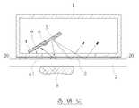
첨부도면 도 1은 본 발명이 적용된 빗방울 감지센서의 개념도와 전면 유리창 표면에 광원과 수광소자가 격자 형태로 부착된 감지판을 전면 유리창에 비스듬히 부착하는 방식의 개념도 이고, 도 2는 센서 내 주변광 영향 감소방식의 개념도 이다.1 is a conceptual diagram of a raindrop detection sensor to which the present invention is applied and a method of attaching a detection plate attached to a front glass window obliquely to a front glass window at a light source and a light receiving element on the front glass window surface, and FIG. 2 is an ambient light in the sensor. A conceptual diagram of impact reduction.
도 1을 참조하면, 참조번호 1은 본 발명에 의한 빗방울 감지센서 외함을 나타내고, 참조번호 2는 자동차 전면 유리창을 나타내고, 참조번호 4는 광원과 수광소자를 격자 모양으로 배열시켜 부착시키는 격자판을 나타내고, 참조번호 5는 광원으로 사용되는 LED를 나타내고, 참조번호 6은 수신된 광 신호를 전기신호로 바꾸기 위한 수광소자를 나타내고, 참조번호 7은 격자판을 고정시키는 브라켓을 나타내고, 참조번호 8은 유리창 표면에 떨어진 빗방울을 나타낸다.Referring to FIG. 1,reference numeral 1 denotes a raindrop detection sensor enclosure according to the present invention,reference numeral 2 denotes a front windshield of an automobile, andreference numeral 4 denotes a grating plate for arranging and attaching a light source and a light receiving element in a grid shape. ,Reference numeral 5 denotes an LED used as a light source,reference numeral 6 denotes a light receiving element for converting a received optical signal into an electrical signal,reference numeral 7 denotes a bracket for fixing a grid plate, andreference numeral 8 denotes a glass window surface. Represents raindrops dropped on.
상기의 구성에서 광원으로 사용되는 LED(5)로부터 출력되는 적외선 신호광은 적외선 필터와 자동차 전면 유리창(2)을 통과하여 유리창 표면에 부착된 빗방울(8)에서 일부가 반사되어 다시 자동차 전면 유리창(2)과 적외선 통과 필터(3)를 통과한 후 LED(5)와 같은 방향에 위치한 수광소자(6)에서 광전변환 된다. 이렇게 광전변환된 전기신호는 수신기에서 신호로 복원된 후 마이컴에 미리 입력된 대조표와 비교하여 수신된 신호에 대응한 유리창 브러쉬 작동신호를 발생하게 된다. 이때 1 단위감지구역에서는 광원으로 사용되는 4 개의 LED(5)가 1 개의 수광소자(6)를 둘러싸는 구조이므로 1 개의 수광소자(6)로 4 개의 경로를 포함시킬 수 있으므로 수광소자 개수 측면에서 경제적이다. 더욱이 인접 감지구역에서는 2 개의 LED(5)와 1 개의 수광소자(6)를 추가하여도 처음 감지구역에서와 같이 4개의 LED(5)를 사용하는 효과를 거두므로 감지면적은 넓히면서 부품수를 줄일 수 있는 장점이 있다.The infrared signal light output from theLED 5 used as the light source in the above configuration passes through the infrared filter and thefront windshield 2 of the vehicle, and is partially reflected from theraindrops 8 attached to the surface of the windshield. After passing through the infrared filter (3) and the infrared filter (3) is photoelectric conversion in the light receiving element (6) located in the same direction as the LED (5). The photoelectrically converted electrical signal is restored to a signal at the receiver and then compared with a control table previously input to the microcomputer to generate a window brush operating signal corresponding to the received signal. In this case, since the fourLEDs 5 used as the light sources surround onelight receiving element 6 in one unit detection area, four light paths may be included as onelight receiving element 6, so It is economical. In addition, the addition of two LEDs (5) and one light-receiving element (6) in the adjacent sensing zone has the effect of using four LEDs (5) as in the first sensing zone, thus increasing the sensing area and reducing the number of parts. There are advantages to it.
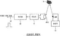
한편, 도 2를 참조하면, 참조번호 9는 수신기를 나타내고, 참조번호 10은 마이컴을 나타내고, 참조번호 11은 송신기를 나타내고, 참조번호 12는 유리창 브러쉬를 작동시키는 빗방울 감지신호를 나타내고, 참조번호 13은 광원을 변조시키는 발진주파수를 생성하는 발진기를 나타내고, 참조번호 14는 변조기를 나타내고, 참조번호 15는 수광소자에서 광전변환된 신호를 증폭하는 증폭기를 나타내고, 참조번호 16은 증폭기 출력에 포함된 신호중에서 당초 송신기에 사용된 변조주파수와 같은 주파수 성분만을 추출하는 대역통과필터를 나타낸다.Meanwhile, referring to FIG. 2, reference numeral 9 denotes a receiver,reference numeral 10 denotes a microcomputer,reference numeral 11 denotes a transmitter,reference numeral 12 denotes a raindrop detection signal for operating a window brush, andreference numeral 13 Denotes an oscillator for generating an oscillation frequency for modulating the light source,reference numeral 14 denotes a modulator,reference numeral 15 denotes an amplifier for amplifying a photoelectrically converted signal in the light receiving element, andreference numeral 16 denotes a signal included in the amplifier output. The bandpass filter extracts only the frequency components such as the modulation frequency used in the transmitter initially.
상기의 구성에서 발진기(13)는 10kHz ~ 100kHz 대의 정현파를 발진하고 이 발진신호에 따라 변조기(14)는 LED(5)를 광변조시킨다. 이렇게 생성된 신호광은 자동차 전면 유리창(2)에 떨어진 빗방울(8)에서 반사되어 자동차 전면 유리창에 부착된 적외선통과필터(3)를 통과한 후 수광소자(6)에 수신된다. 이때 적외선통과필터(3)는 신호광 이외의 가시광선 대역의 외부광이 수신되는 것을 억제하는 효과를 가져온다. 수광소자에서 광전변환된 전기신호는 증폭기(15)에서 증폭된 후 대역통과필터(16)에서 당초 발진기(13)의 발진주파수와 동일한 주파수 성분만을 걸러내게 된다. 이러한 방법으로 신호광 이외의 외부광의 영향을 대부분 차단할 수 있게 된다. 이렇게 생성된 신호광의 크기는 마이컴에서 미리 입력된 대조표(Look-up Table)에 따라 적합한 자동차 유리창 브러쉬의 작동빈도를 결정하고 이를 출력(12)하도록 하였다.In the above configuration, theoscillator 13 oscillates a sine wave in the range of 10 kHz to 100 kHz, and themodulator 14 light modulates theLED 5 according to the oscillation signal. The generated signal light is reflected by theraindrops 8 falling on thefront windshield 2 of the vehicle and passed through the infraredlight passing filter 3 attached to the front windshield of the vehicle, and then received by thelight receiving element 6. At this time, theinfrared filter 3 has an effect of suppressing the reception of external light in the visible light band other than the signal light. The electrical signal photoelectrically converted by the light receiving element is amplified by theamplifier 15 and then, in theband pass filter 16, filters out only frequency components equal to the oscillation frequency of theoscillator 13 at first. In this way, it is possible to block most of the influence of external light other than the signal light. The size of the signal light generated in this way is to determine the operation frequency of the suitable vehicle windshield brush according to a look-up table input in advance from the microcomputer and to output it.
도 3은 본 발명의 빗방울 감지센서가 자동차의 유리창에 설치된 상태를 개념적으로 보여주는 도면, 도 4는 본 발명의 주요부인 광원의 빛이 유리창 표면에서 반사되는 과정을 개념적으로 보여주는 도면, 도 5는 본 발명의 주요부인 광원의 빛이 빗방울에 반사되어 수광소자로 수광되는 과정을 개념적으로 보여주는 도면, 도 6은 본 발명의 주요부인 광원과 수광소자의 배치 상태의 제1실시예를 개념적으로 보여주는 도면, 도 7은 본 발명의 주요부인 광원과 수광소자의 배치 상태의 제2실시예를 개념적으로 보여주는 도면, 도 8은 본 발명의 주요부인 광원의 펄스 신호 상태를 보여주는 그래프, 도 9는 본 발명의 빗방울 감지센서의 신호감지 개념도와 주변광 영향 감소방식의 개념도이다.3 is a view conceptually showing a state in which the raindrop sensor of the present invention is installed on the windshield of the vehicle, FIG. 4 is a view conceptually showing a process in which light of a light source, which is a main part of the present invention, is reflected from the surface of the windshield, FIG. Conceptually showing a process in which light of a light source, which is a main part of the invention, is reflected by raindrops and received by a light receiving element, FIG. 6 conceptually shows a first embodiment of an arrangement of a light source and a light receiving element, which is a main part of the present invention; 7 is a conceptual view illustrating a second embodiment of an arrangement state of a light source and a light receiving element, which are main parts of the present invention, FIG. 8 is a graph showing a pulse signal state of a light source that is a main part of the present invention, and FIG. 9 is a raindrop of the present invention. This is a conceptual diagram of the signal detection concept of the sensor and the method of reducing the influence of ambient light.
이러한 도 3 내지 도 9에 의한 본 발명은 유리창에 부착되는 케이스(1)의 내부에 광원(5)과 수광소자(6)를 탑재한 기판(4)이 내장되며, 광원(5)과 수광소자(6)를 탑재한 기판(4)은 유리창(2) 표면에 대해 경사지게 배치된 구조를 이룬다.3 to 9, thesubstrate 4 on which thelight source 5 and thelight receiving element 6 are mounted is embedded in thecase 1 attached to the glass window, and thelight source 5 and the light receiving element are embedded therein. The board |substrate 4 which mounted 6 has the structure arrange | positioned inclined with respect to the surface of theglass window 2. As shown in FIG.
상기 케이스(1)는 자동차 유리창(2)과 마주하는 면에 개구부(3)가 형성된 대략 사각의 함체 형상으로 이루어진 것으로, 개구부(3)의 외측면에는 양면 테이프(20)가 구비되어, 양면 테이프(20)에 의해 자동차의 유리창(2) 표면에 부착된다.Thecase 1 is formed in a substantially rectangular enclosure having anopening 3 formed on a surface facing theautomotive window 2, and a double-sided tape 20 is provided on an outer surface of theopening 3. It is attached to the surface of thewindshield 2 of the automobile by the 20.
상기 케이스(1)의 내부에는 광원(5)과 수광소자(6)를 탑재한 기판(4)이 구비된다. 이때, 기판(4)은 브라켓과 같은 지지구(7)(도 5에 도시됨)에 의해 케이스(1)의 개구부(3)에 대해 경사진 형태로 배열되어, 광원(5)과 수광소자(6)가 자동차 유리창(2)의 표면에 대해 경사지게 설치된다. 기판(4)이 유리창(2) 표면에 대해 경사진 각도는 90°를 넘지 않는 예각 범위이다.Thecase 1 is provided with asubstrate 4 on which thelight source 5 and thelight receiving element 6 are mounted. At this time, thesubstrate 4 is arranged in an inclined form with respect to theopening 3 of thecase 1 by a support 7 (shown in FIG. 5), such as a bracket, so that thelight source 5 and the light receiving element ( 6) is installed inclined with respect to the surface of theautomobile windshield 2. The angle at which thesubstrate 4 is inclined with respect to the surface of thewindow 2 is an acute angle range not exceeding 90 °.
그리고, 이때, 상기 광원(5)으로는 적외선 엘이디를 채용하고, 상기 수광소자(6)는 적외선 센서로 채용한 것이 다른 특징을 이루는데, 이러한 특징에 대해서는 후술하기로 한다.In this case, an infrared LED is used as thelight source 5, and thelight receiving element 6 is used as an infrared sensor, which will be described later.
이러한 구성의 본 발명에 의하면, 우천시 광원(5)으로 사용되는 적외선 엘이디로부터 출력되는 적외선 신호광이 케이스(1)의 개구부(3)를 통해 자동차 전면 유리창(2)을 투과하여 유리창(2) 표면에 묻은 빗방울(8)에서 일부가 반사되어 다시 자동차 전면 유리창(2)을 통과한 후 광원(5)인 적외선 엘이디와 인접된 수광소자(6)에서 광전변환되고, 이렇게 광전변환된 전기신호는 수신기(9)에서 신호로 복원된 후 마이컴(10)에 미리 입력된 대조표와 비교하여 수신된 신호에 대응한 유리창(2) 와이퍼 작동신호를 발생하게 된다. 그리고, 상기와 같이 생성된 신호광의 크기는 마이컴(10)에서 미리 입력된 대조표(Look-up Table)에 따라 적합한 자동차 유리창(2) 와이퍼의 작동빈도를 결정한다.According to the present invention of such a configuration, the infrared signal light output from the infrared LED used as the light source (5) in rainy weather passes through the front windshield (2) of the vehicle through the opening (3) of the case (1) to the surface of the glass window (2) Partial reflection from theraindrops 8 is passed through thefront windshield 2 of the vehicle, and then photoelectrically converted by thelight emitting element 6 adjacent to the infrared LED which is thelight source 5. After the signal is restored in 9), the wiper operation signal for thewindshield 2 corresponding to the received signal is generated in comparison with the control table previously input to themicrocomputer 10. In addition, the size of the signal light generated as described above determines the operation frequency of thewindshield wiper 2 suitable for thevehicle window 2 according to a look-up table previously input from themicrocomputer 10.
이때, 수광소자(6)와 광원(5)을 탑재한 기판(4)이 유리창(2) 표면에 대해 경사지게 배치되어, 광원(5)에서부터 발산되는 광이 자동차 유리창(2)에 입사되면서 유리창(2) 표면에서 반사된 빛은 수광소자(6)에서 수광되지 않고 외부로 빠지고, 유리창(2)에 입사된 광은 밀도의 차이에 의하여 일정한 각도로 굴절되고, 굴절된 광은 유리창(2) 바깥면에서 소멸되는 한편, 유리창(2) 내부를 투과한 광은 빗방울(8)을 통과하며 일정각도로 굴절되어 빗방울(8)의 외부 표면에서 광이 난반사되고, 수광소자(6)에서는 빗방울(8)에서 난반사되는 광만을 수신하면서 유리창(2) 표면에서 반사되는 빛의 영향을 최소화시키기 때문에, 빗방울(8)에 의한 반사가 아닌 차량의 전면 유리창(2) 표면에서 반사되는 반사광의 영향을 받음으로 인하여 신호대 잡읍비가 저하되는 경우를 방지하는 효과가 있고, 이는 빗방울(8) 감지 효율성에 있어서 기대한 만큼의 성능을 충분히 달성할 수 있으며, 자동차의 경우 와이퍼의 회동 속도를 정밀하게 조절하여 충분한 효율성을 거둘 수 있음을 의미한다. 이를테면, 본 발명은 유리창(2) 표면에서 직접 반사되는 광량을 최소화시키는 한편, 빗방울(8)에서 난반사되는 광만을 수광하므로, 빗방울(8) 센싱 성능 향상 등에 매우 효율적인 것이다.At this time, thesubstrate 4 on which thelight receiving element 6 and thelight source 5 are mounted is disposed to be inclined with respect to the surface of theglass window 2, so that the light emitted from thelight source 5 is incident on theautomobile glass window 2. 2) The light reflected from the surface is not received by the light-receivingelement 6, but the light exits to the outside, the light incident on theglass window 2 is refracted at a certain angle due to the difference in density, and the refracted light is outside theglass window 2 While extinguished in the plane, the light transmitted through the inside of theglass window 2 passes through theraindrops 8 and is refracted at a predetermined angle so that the light is diffusely reflected on the outer surface of theraindrops 8, and in thelight receiving element 6, theraindrops 8 Since it minimizes the influence of light reflected from the surface of theglass window 2 while receiving only light that is diffusely reflected from the surface, it is affected by the reflected light reflected from the surface of thewindshield 2 of the vehicle rather than by theraindrop 8. Prevents signal tower cost Means that the effect is there, it can be sufficiently achieved performance as expected in the raindrop (8) sensing the efficiency, in the case of the automobile can achieve a sufficient efficiency by precisely controlling the rotational speed of the wiper. For example, the present invention minimizes the amount of light reflected directly from the surface of theglass window 2 and receives only the light that is diffusely reflected from theraindrops 8, thus improving the sensing performance of theraindrops 8.
결국, 본 발명은 광원(5)과 수광소자(6)인 센서를 탑재한 기판(4)을 유리창(2) 표면에 대해 경사지게 배치함으로 인하여, 유리창(2) 표면에서 반사되는 광의 영향을 최소하는 반면, 빗방울(8) 자체에서 반사되는 광신호만을 수신하여 레인 센싱 효율을 높일 수 있다는 점에 가장 큰 특징이 있는 발명이라 하겠다.As a result, the present invention minimizes the influence of the light reflected from the surface of theglass window 2 by arranging thesubstrate 4 on which thelight source 5 and the sensor, which are thelight receiving elements 6, are mounted inclined with respect to the surface of theglass window 2. On the other hand, it is the invention that has the greatest feature in that it can increase the rain sensing efficiency by receiving only the optical signal reflected from the raindrop (8) itself.
또한, 도 2와 도 3에 도시된 바와 같이, 광원(5)에서 조사되는 광은 점차적으로 확산되는 형태로 조사되는데, 광원(5)의 조사되는 광 중에서 상기 수광소자(6)측을 향하는 면의 조사광의 각도(a)는 유리창(2)에 대해 예각 범위(즉, 90ㅀ 이하의 각도 범위)로 광 조사 각도를 맞추어 준다.In addition, as shown in FIGS. 2 and 3, the light irradiated from thelight source 5 is irradiated in a form of being gradually diffused, and the surface of thelight source 5 facing thelight receiving element 6 side is irradiated. The angle a of the irradiated light is adjusted to the light irradiation angle in the acute angle range (ie, the angle range of 90 degrees or less) with respect to theglass window 2.
따라서, 유리창(2)에서 직접 반사되는 광은 수광소자(6)의 수광 범위 바깥으로 빠져서 유리창(2)에 반사되어 수광소자(6)에 의해 수신되는 광량을 최소화시키는 반면, 빗방울(8)에서 반사되는 광량만을 수광소자(6)에 수신하므로, 빗방울(8)로부터의 난반사 신호만을 감지할 수 있게 된다.Thus, the light reflected directly from theglass window 2 falls outside the light receiving range of thelight receiving element 6 and is reflected by theglass window 2 to minimize the amount of light received by thelight receiving element 6, while in theraindrop 8 Since only the amount of reflected light is received by thelight receiving element 6, only the diffuse reflection signal from theraindrop 8 can be detected.
이때, 상기 케이스(1)는 개구부(3)가 형성된 면에 양면테이프(20)가 구비되어, 양면테이프(20)에 의해 수광소자(6)와 광원(5)이 탑재된 기판(4)을 내장한 케이스(1)가 유리창(2) 표면에 신속 용이하게 탈부착될 수 있게 된다.At this time, thecase 1 is provided with a double-sided tape 20 on the surface on which theopening 3 is formed, and thesubstrate 4 on which thelight receiving element 6 and thelight source 5 are mounted by the double-sided tape 20. The built-incase 1 can be quickly and easily attached to and detached from theglass window 2 surface.
한편, 본 발명은 도5와 같이 수광소자(6)의 전후 좌우 방향으로 복수개의 광원(5)이 격자형으로 배열된 구성을 취한다. 구체적으로, 수광소자(6)의 전후 좌우 방향으로 격자형으로 복수개의 광원(5)이 배열되어 구성된다.Meanwhile, the present invention has a configuration in which a plurality oflight sources 5 are arranged in a lattice shape in the front-rear and left-right directions of thelight receiving element 6 as shown in FIG. Specifically, a plurality oflight sources 5 are arranged in a lattice shape in the front, rear, left and right directions of thelight receiving element 6.
따라서, 1 단위감지구역에서는 광원(5)으로 사용되는 4 개의 엘이디가 1 개의 수광소자(6)를 둘러싸는 구조이므로, 1 개의 수광소자(6)로 4 개의 경로를 포함시킬 수 있으므로 수광소자(6) 개수 측면에서 경제성을 기할 수 있으면서도 빗방울(8) 감지 영역은 더 넓힐 수 있는 효과를 갖는다.Therefore, in the one unit detection zone, since the four LEDs used as thelight sources 5 surround onelight receiving element 6, four light paths may be included in onelight receiving element 6, so that the light receiving element ( 6) In terms of number, theraindrop 8 detection area can be made wider while economical.
아울러, 상기 1단위 감지구역(즉, 1개의 수광소자(6)와 4개의 광원(5)이 배열된 감지구역)에 추가로 2개의 광원(5)과 1개의 수광소자(6)를 각각 배치하여 감지구역을 확장할 수 있으므로, 인접 감지구역에서는 2 개의 LED(5)와 1 개의 수광소자(6)를 추가하여도 처음 감지구역에서와 같이 4개의 LED(5)를 사용하는 효과를 거두므로 빗방울(8) 감지면적은 더욱 넓힐 수 있으면서도 부품수를 줄일 수 있는 장점이 있다.In addition, two additionallight sources 5 and onelight receiving element 6 are respectively disposed in the one unit detection zone (that is, the detection zone in which onelight receiving element 6 and fourlight sources 5 are arranged). Since the detection zone can be expanded, the addition of two LEDs (5) and one light receiving element (6) in the adjacent detection zone has the effect of using four LEDs (5) as in the first detection zone. Raindrops (8) detection area has an advantage that can reduce the number of parts while wider.
한편, 본 발명은 광원(5)이 적외선 엘이디로 구성되고, 수광소자(6)도 적외선 센서로 구성된 것에도 역시 특징이 있다. 즉, 적외선은 가시광선에 비해 파장이 긴 비가시광선으로서, 광원(5)인 적외선 엘이디는 외부광보다 강한 수십배의 적외선을 발산하고, 수광소자(6)인 적외선 센서는 비가시광선만을 수광하여, 야간 우천시 차량 운행 중에 와이퍼 작동에 의한 상대편 차량의 헤드라이트 빛은 수광하지 않고 적외선 엘이디에서 발산되어 빗방울로부터 반사되는 비가시광선만 수광하므로, 외부광의 영향을 받지 않고 효율적으로 작동하게 된다. 즉, 적외선 엘디이가 가시광선을 쓰지 않고 수광소자(6)인 적외선 센서도 가시광선을 수광하지 않아서, 와이퍼의 왕복에 의한 상대편 차량의 광신호는 제외되므로, 오동작을 미연에 방지하는 등의 효과가 있는 것이다.On the other hand, the present invention is also characterized in that thelight source 5 is composed of an infrared LED, and thelight receiving element 6 is also composed of an infrared sensor. That is, infrared rays are invisible light having a longer wavelength than visible light, and the infrared LED as thelight source 5 emits several tens of times stronger infrared rays than external light, and the infrared sensor as thelight receiving element 6 receives only invisible light. In the rainy weather at night, the headlights of the other vehicle by the wiper operation are not received, but only the invisible light emitted from the infrared LED and reflected from the raindrops, thus effectively operating without being affected by external light. That is, since the infrared LED does not use visible light and the infrared sensor which is thelight receiving element 6 does not receive the visible light, the optical signal of the other vehicle caused by the reciprocation of the wiper is excluded, thus preventing the malfunction in advance. It is.
또한, 케이스(1)의 내부는 빛을 흡수하기 위해 검은 색과 난반사 처리가 된 구조를 취하여, 수광소자(6)를 내장한 부분의 내부에 빛을 흡수하는 검은색과 난반사 처리에 의하여 유리창(2) 표면에서 반사된 빛은 대부분 소멸되기 때문에, 빗방울(8) 이외의 부분에서 반사된 광에 의한 영향을 더 확실하게 줄일 수 있게 된다.In addition, the inside of thecase 1 has a structure in which black and diffuse reflection are treated to absorb light, and the glass window (black and diffuse reflection which absorbs light in the interior of the light-receivingelement 6 is absorbed). 2) Since most of the light reflected from the surface is extinguished, the influence by the light reflected from parts other than theraindrops 8 can be more surely reduced.
이때, 도 6에 도시된 바와 같이, 광원(5)인 적외선 엘이디는 펄스 신호로 광신호를 내도록 설계되어, 순간적으로 수백 mA의 파워를 가진 펄스 광신호를 내도록 설계되고, 상기 수광소자(6)가 짧은 광신호에는 반응하지 않도록 타임 딜레이를 주어 설계되었으므로, 감지 효율성을 보다 높이는 효과를 기대할 수 있게 된다. 즉, 와이퍼가 작동할 때 순간적으로 발생하는 짧은 광신호에는 반응하지 않도록 타임 딜레이를 주었기 때문에, 감지 효율성을 보다 확실하게 높일 수 있는 것이다.At this time, as shown in Fig. 6, the infrared LED which is thelight source 5 is designed to give an optical signal as a pulse signal, and is designed to give a pulsed optical signal having a power of several hundred mA instantaneously, and thelight receiving element 6 Is designed to give a time delay so that it does not respond to a short optical signal, it can be expected to increase the detection efficiency. In other words, the time delay is provided so that it does not react to the short optical signal generated when the wiper is operating, and thus the sensing efficiency can be more surely increased.
도 7은 본 발명의 빗방울 감지센서에 의한 주변광 영향 감소방식의 개념도를 보여주는데, 본 발명의 경우, 송신기(11)에서 생성된 신호에 따라 광원(5)이 신호광을 송출하는데, 본 발명에서 송신기(11)는 10kHz ~ 100kHz 대의 구형파를 발진하는 발진기(13)와 발진신호에 따라 적외선 엘이디 광원(5)을 광 변조시키는 변조기(14)로 구성되고, 수신기(9)는 수광소자(6)에서 광전변환된 전기신호를 증폭하는 증폭기(15)와, 발진기(13)의 발진주파수와 동일한 주파수 성분만을 걸러내는 대역통과필터(16)로 구성된다.Figure 7 shows a conceptual diagram of the ambient light effect reduction method by the raindrop detection sensor of the present invention, in the case of the present invention, thelight source 5 transmits the signal light according to the signal generated by thetransmitter 11, the transmitter in thepresent invention 11 includes anoscillator 13 for oscillating a square wave in the range of 10 kHz to 100 kHz and amodulator 14 for optically modulating the infraredLED light source 5 in accordance with an oscillation signal, and the receiver 9 in thelight receiving element 6 Anamplifier 15 for amplifying the photoelectrically converted electric signal, and aband pass filter 16 for filtering only frequency components equal to the oscillation frequency of theoscillator 13.
상기 발진기(13)는 10kHz ~ 100kHz 대의 정현파를 발진하고 이 발진신호에 따라 변조기(14)는 엘이디(5)를 광변조시킨다. 이렇게 생성된 신호광은 자동차 전면 유리창(2)에 떨어진 빗방울(8)에서 반사되어 수광소자(6)에 수신된다. 수광소자에서 광전변환된 전기신호는 증폭기(15)에서 증폭된 후 대역통과필터(16)에서 당초 발진기(13)의 발진주파수와 동일한 주파수 성분만을 걸러내게 된다. 이렇게 생성된 신호광의 크기는 마이컴(10)에서 미리 입력된 대조표(Look-up Table)에 따라 적합한 자동차 유리창 와이퍼의 작동빈도를 결정하고 이를 출력(12)함으로써, 와이퍼를 강우량에 대응하여 작동시키게 되는 것이다.Theoscillator 13 oscillates a sine wave in the range of 10 kHz to 100 kHz, and themodulator 14 optically modulates theLED 5 according to the oscillation signal. The generated signal light is reflected by theraindrops 8 falling on thefront windshield 2 of the vehicle and received by thelight receiving element 6. The electrical signal photoelectrically converted by the light receiving element is amplified by theamplifier 15 and then, in theband pass filter 16, filters out only frequency components equal to the oscillation frequency of theoscillator 13 at first. The size of the generated signal light determines the operation frequency of the suitable windshield wiper according to the look-up table input in advance from themicrocomputer 10 and outputs it to operate the wiper in response to rainfall. will be.
본 발명은 광학계가 간소화되고 설치가 용이하며, 유리창에 빛을 투과시키는 광원과 빗방울에서 반사되는 광을 집수하는 수광소자를 유리창 표면에 대해 경사지게 설치함으로써, 빗방울에 의한 반사가 아닌 차량의 전면 유리창 표면에서 반사되는 반사광의 영향을 받음으로 인하여 신호대 잡읍비가 저하되는 경우를 최소화시키며, 아울러, 와이퍼의 왕복에 의한 광신호는 수신하지 않도록 설계되어, 와이퍼 작동 순간에 상대편 차량의 헤드라이트의 영향을 받는 경우를 방지하므로, 작동 신뢰성 등을 현저히 향상시킬 수 있는 빗방울 감지센서로 이용될 수 있다.The present invention is simplified and easy to install the optical system, by installing a light source that transmits light to the glass window and a light receiving element that collects the light reflected from raindrops inclined with respect to the glass window surface, the front window surface of the vehicle rather than reflection by raindrops Minimizes the case where signal-to-stage ratio is lowered due to the reflected light reflected from, and it is designed not to receive the optical signal due to the reciprocation of the wiper, and is affected by the headlights of the other vehicle at the moment of wiper operation. Since it can prevent, it can be used as a raindrop sensor that can significantly improve the operation reliability and the like.
Claims (16)
- 우천시에 내리는 빗물을 감지하는 빗방울 감지장치에 있어서, 송신기(11)에서 생성된 신호에 따라 신호광을 송출하는 광원(5)과, 단위 감지 구역에서 상기 광원(5)에서 조사된 광이 물방울에 반사되어 돌아오는 방향으로 4개의 광원(5)에 둘러싸여 배치되어 수신하는 수광소자(6)와, 빗방울 감지센서 케이스의 일측에 형성된 개구부에 장착되는 적외선 필터와, 자동차 전면 유리창(2) 표면에서의 반사에 의한 잡음요소를 배제하면서도 신호광에 포함된 변조주파수 성분만을 추출하여 유리창 표면의 빗방울 존재량을 판단하므로 빗방울에 의한 반사성분이 아닌 외부광에 의한 영향을 최소화시켜 빗방울 감지 확률을 높여주는 수신기(9)로 구성된 것을 특징으로 하는 빗방울 감지장치.A raindrop detection device for detecting rainwater falling in rainy weather, comprising: a light source (5) for transmitting signal light according to a signal generated by the transmitter (11), and the light irradiated from the light source (5) in a unit detection zone is reflected on water droplets The light-receiving element 6 arranged and surrounded by four light sources 5 in a returning direction, an infrared filter mounted at an opening formed at one side of the raindrop sensor case, and reflection from the surface of the front windshield 2 of the vehicle. The receiver detects the amount of raindrops on the surface of the glass window by removing only the modulation frequency components included in the signal light while eliminating the noise component due to the noise. Raindrop detection device characterized in that consisting of.
- 제 1항에 있어서, 상기 광원(5)에서 조사된 광이 물방울에 반사되어 돌아오는 방향으로 4개의 광원(5)에 둘러싸여 배치되어 수신하는 수광소자(6)로 구성된 단위 감지구역의 좌우 또는 상하로 격자 형태로 2개의 광원(5)과 1개의 수광소자(6)를 각각 추가 배치하여 감지구역을 확장하는 것을 특징으로 하는 빗방울 감지장치.2. The left and right or up and down sides of the unit detection zone according to claim 1, wherein the light irradiated from the light source 5 is arranged surrounded by four light sources 5 in a direction in which the light emitted from the light source 5 is reflected and returned. Raindrop detection device, characterized in that to extend the detection zone by additionally placing two light sources (5) and one light receiving element (6) in the form of a lattice.
- 제 1항에 있어서, 상기 광원(5)은 수광소자(6)와 격자 형태로 배치되며, 적외선 LED인 것을 특징으로 하는 빗방울 감지장치.The raindrop detection device according to claim 1, wherein the light source (5) is arranged in a lattice form with the light receiving element (6).
- 제 1항에 있어서, 상기 빗방울 감지센서 케이스(1)의 내부에 빛을 흡수하는 검은 색과 난반사 처리가 된 것을 특징으로 하는 빗방울 감지장치.The raindrop detection device according to claim 1, wherein the raindrop detection sensor case (1) has a black color and diffuse reflection processing to absorb light.
- 제 1항에 있어서, 상기 송신기(11)는 10kHz ~ 100kHz 대의 구형파를 발진하는 발진기(13)와 발진신호에 따라 적외선 LED 광원(5)을 광 변조시키는 변조기(14)로 구성된 것을 특징으로 하는 빗방울 감지장치.The raindrop of claim 1, wherein the transmitter 11 comprises an oscillator 13 for oscillating a square wave in the range of 10 kHz to 100 kHz and a modulator 14 for optically modulating the infrared LED light source 5 according to an oscillation signal. Sensing device.
- 제 5항에 있어서, 상기 수신기(9)는 수광소자(6)에서 광전변환된 전기신호를 증폭하는 증폭기(15)와, 상시 발진기(13)의 발진주파수와 동일한 주파수 성분만을 걸러내는 대역통과필터(16)로 구성된 것을 특징으로 하는 빗방울 감지장치.The band pass filter of claim 5, wherein the receiver 9 filters only the frequency component equal to the oscillation frequency of the amplifier 15 and the oscillator 13 which amplifies the electric signal photoelectrically converted by the light receiving element 6. Raindrop detection device characterized in that consisting of (16).
- 제 6항에 있어서, 상기 수광소자(6) 전면에 장착된 적외선 필터는 신호 광 이외의 가시광선 대역의 외부 광이 수신되는 것을 억제하는 것을 특징으로 하는 빗방울 감지장치.7. The raindrop detection device according to claim 6, wherein the infrared filter mounted on the front surface of the light receiving element (6) suppresses the reception of external light in the visible light band other than the signal light.
- 제 1항 내지 제 7항 중 어느 한 항에 있어서, 상기 수신기(9)는 신호 광의 크기에 따라 정보를 마이컴(10)에 전달하고, 마이컴(10)은 미리 입력된 대조표(Look-up Table)에 따라 적합한 자동차 유리창 브러시의 작동빈도를 결정하고 빗방울 감지 신호(12)를 출력하는 것을 특징으로 하는 빗방울 감지장치.8. The receiver (9) according to any one of claims 1 to 7, wherein the receiver (9) transmits information to the microcomputer (10) according to the magnitude of the signal light, and the microcomputer (10) has a previously entered look-up table. Raindrop detection device, characterized in that for determining the operating frequency of the suitable vehicle windshield brush and outputs a raindrop detection signal (12).
- 우천시에 내리는 빗물을 감지하는 빗방울 감지센서에 있어서, 차량의 유리창(2)에 빛을 투과시키도록 광을 조사하는 광원(5)과, 상기 광원(5)에서 조사된 빛이 상기 유리창(2)에 떨어진 빗방울로부터 반사될 때의 광신호를 센싱하여 광전 변환하는 수광소자(6)와, 상기 수광소자(6)의 광전 변환된 신호를 수신하여 강우 정도를 판단하는 수신기(9)를 포함하여 구성되며, 상기 광원(5)과 상기 수광소자(6)는 상기 유리창(2) 표면에 대해 경사지게 배치되어 상기 유리창(2)에서 직접 반사된 광원(5)의 빛은 수광소자(6)의 외측으로 빠지고 상기 유리창(2)에 묻은 빗방울(8)에서 반사된 빛을 상기 수광소자(6)가 수신하여 차량의 와이퍼를 작동시키며, 상기 광원(5)과 상기 수광소자(6)는 기판(4)에 탑재되고, 상기 기판(4)이 상기 유리창(2) 표면에 대해 경사지도록 배치되어, 상기 광원(5)과 상기 수광소자(6)가 상기 유리창(2) 표면에 경사지게 배치된 것을 특징으로 하는 빗방울 감지센서.In the raindrop detection sensor for detecting rainwater falling in rainy weather, a light source (5) for irradiating light to transmit the light through the window (2) of the vehicle, and the light irradiated from the light source (5) is the window (2) A light receiving element 6 for sensing and photoelectrically converting an optical signal when it is reflected from raindrops falling on the light; and a receiver 9 for receiving the photoelectrically converted signal of the light receiving element 6 and determining a degree of rainfall. The light source 5 and the light receiving element 6 are disposed to be inclined with respect to the surface of the window 2 so that the light of the light source 5 reflected directly from the window 2 is directed toward the outside of the light receiving element 6. The light-receiving element 6 receives the light reflected from the raindrops 8 on the window 2 and operates the wiper of the vehicle, and the light source 5 and the light-receiving element 6 are the substrate 4. Mounted on the substrate 4 so that the substrate 4 is inclined with respect to the surface of the glass window 2 The raindrop sensor, characterized in that the light source (5) and the light receiving element (6) is inclined on the surface of the glass window (2).
- 제 9 항에 있어서, 상기 수광소자(6)의 전후 좌우 방향으로 복수개의 광원(5)이 격자형으로 배열되어 구성된 것을 특징으로 하는 빗방울 감지센서.10. The raindrop sensor according to claim 9, wherein a plurality of light sources (5) are arranged in a lattice shape in the front, rear, left, and right directions of the light receiving element (6).
- 제 10 항에 있어서, 상기 수광소자(6)의 전후 좌우 방향으로 격자형으로 복수개의 광원(5)이 배열된 단위 감지구역의 좌우 또는 상하로 격자형으로 2개의 광원(5)과 1개의 수광소자(6)를 각각 추가 배치하여 감지구역을 확장하는 것을 특징으로 하는 빗방울 감지센서.12. The light receiving device according to claim 10, wherein two light sources 5 and one light receiver are lattice in the horizontal direction of the unit sensing area in which the plurality of light sources 5 are arranged in a grid shape in the front, rear, left, and right directions of the light receiving element 6. Raindrop detection sensor, characterized in that to extend the detection zone by further placing each element (6).
- 제 9 항에 있어서, 상기 광원(5)은 적외선 엘이디로 구성되고, 상기 수광소자(6)는 적외선 센서로 이루어진 것을 특징으로 하는 빗방울 감지센서.10. The raindrop sensor according to claim 9, wherein the light source (5) comprises an infrared LED and the light receiving element (6) comprises an infrared sensor.
- 제 9 항에 있어서, 상기 광원(5)의 빛이 조사되는 차량의 유리창(2)에는 전면의 개구부(3)가 마주하도록 케이스(1)가 설치되고, 상기 케이스(1)의 내부에는 상기 광원(5)과 상기 수광소자(6)가 탑재된 기판(4)이 내장되고, 상기 광원(5)과 수광소자(6)를 탑재한 상기 기판(4)은 상기 유리창(2)에 대해 경사지게 설치되며, 상기 케이스(1)의 내부는 빛을 흡수하기 위해 난반사 처리가 된 것을 특징으로 하는 빗방울 감지센서.10. The method according to claim 9, wherein the case (1) is installed in the glass window (2) of the vehicle to which the light of the light source 5 is irradiated so as to face the opening (3) in the front, the inside of the case (1) A substrate 4 on which the light receiving element 6 is mounted is embedded, and the substrate 4 on which the light source 5 and the light receiving element 6 are mounted is inclined with respect to the glass window 2. The inside of the case (1) is raindrop detection sensor, characterized in that the diffuse reflection treatment to absorb light.
- 제 13 항에 있어서, 상기 광원(5)인 적외선 엘이디는 펄스 신호로 광신호를 내도록 설계되어, 상기 수광소자(6)가 상기 광원(5)의 펄스 신호가 아닌 짧은 주변 광에는 반응하지 않도록 타임 딜레이를 주어 설계된 것을 특징으로 하는 빗방울 감지센서.15. The light emitting device according to claim 13, wherein the infrared LED, which is the light source 5, is designed to emit an optical signal with a pulse signal so that the light receiving element 6 does not react to short ambient light other than the pulse signal of the light source 5. Raindrop sensor, characterized in that the delay is designed.
- 제 9 항에 있어서, 상기 광원(5)은 송신기(11)에서 생성된 신호에 따라 신호광을 송출하도록 구성되며, 상기 송신기(11)는 10kHz ~ 100kHz 대의 구형파를 발진하는 발진기(13)와 발진신호에 따라 적외선 엘이디 광원(5)을 광 변조시키는 변조기(14)로 구성된 것을 특징으로 하는 빗방울 감지센서.10. The oscillator (13) according to claim 9, wherein the light source (5) is configured to emit signal light according to the signal generated by the transmitter (11), and the transmitter (11) oscillator (13) and an oscillation signal for oscillating a square wave in the range of 10 kHz to 100 kHz Rain sensor according to claim 1, characterized in that consisting of a modulator (14) for light modulating the infrared LED light source (5).
- 제 15 항에 있어서, 상기 수신기(9)는 수광소자(6)에서 광전변환된 전기신호를 증폭하는 증폭기(15)와, 상시 발진기(13)의 발진주파수와 동일한 주파수 성분만을 걸러내는 대역통과필터(16)로 구성된 것을 특징으로 하는 빗방울 감지센서.16. The band pass filter of claim 15, wherein the receiver 9 filters only the frequency component equal to the oscillation frequency of the amplifier 15 and the oscillator 13 which amplifies the electric signal photoelectrically converted by the light receiving element 6. Raindrop sensor, characterized in that consisting of (16).
Priority Applications (4)
| Application Number | Priority Date | Filing Date | Title |
|---|---|---|---|
| JP2011506181AJP5600313B2 (en) | 2008-04-21 | 2009-04-03 | Raindrop sensor |
| EP09734320AEP2277751A2 (en) | 2008-04-21 | 2009-04-03 | Raindrop sensor |
| CN2009801139150ACN102015384B (en) | 2008-04-21 | 2009-04-03 | rain sensor |
| US12/988,428US8471513B2 (en) | 2008-04-21 | 2009-04-03 | Rain sensor |
Applications Claiming Priority (4)
| Application Number | Priority Date | Filing Date | Title |
|---|---|---|---|
| KR1020080036853AKR101254131B1 (en) | 2008-04-21 | 2008-04-21 | Rain sensor in grid structure with improved area detection efficiency |
| KR10-2008-0036853 | 2008-04-21 | ||
| KR1020080105209AKR100880248B1 (en) | 2008-10-27 | 2008-10-27 | Raindrop Sensor |
| KR10-2008-0105209 | 2008-10-27 |
Publications (2)
| Publication Number | Publication Date |
|---|---|
| WO2009131316A2true WO2009131316A2 (en) | 2009-10-29 |
| WO2009131316A3 WO2009131316A3 (en) | 2010-02-18 |
Family
ID=41217230
Family Applications (1)
| Application Number | Title | Priority Date | Filing Date |
|---|---|---|---|
| PCT/KR2009/001739WO2009131316A2 (en) | 2008-04-21 | 2009-04-03 | Raindrop sensor |
Country Status (5)
| Country | Link |
|---|---|
| US (1) | US8471513B2 (en) |
| EP (1) | EP2277751A2 (en) |
| JP (1) | JP5600313B2 (en) |
| CN (1) | CN102015384B (en) |
| WO (1) | WO2009131316A2 (en) |
Cited By (118)
| Publication number | Priority date | Publication date | Assignee | Title |
|---|---|---|---|---|
| CN102346264A (en)* | 2010-07-30 | 2012-02-08 | 比亚迪股份有限公司 | Rainfall sensor and rainfall detection method |
| US9674711B2 (en) | 2013-11-06 | 2017-06-06 | At&T Intellectual Property I, L.P. | Surface-wave communications and methods thereof |
| US9685992B2 (en) | 2014-10-03 | 2017-06-20 | At&T Intellectual Property I, L.P. | Circuit panel network and methods thereof |
| US9705561B2 (en) | 2015-04-24 | 2017-07-11 | At&T Intellectual Property I, L.P. | Directional coupling device and methods for use therewith |
| US9705610B2 (en) | 2014-10-21 | 2017-07-11 | At&T Intellectual Property I, L.P. | Transmission device with impairment compensation and methods for use therewith |
| US9729197B2 (en) | 2015-10-01 | 2017-08-08 | At&T Intellectual Property I, L.P. | Method and apparatus for communicating network management traffic over a network |
| US9735833B2 (en) | 2015-07-31 | 2017-08-15 | At&T Intellectual Property I, L.P. | Method and apparatus for communications management in a neighborhood network |
| US9742462B2 (en) | 2014-12-04 | 2017-08-22 | At&T Intellectual Property I, L.P. | Transmission medium and communication interfaces and methods for use therewith |
| US9749013B2 (en) | 2015-03-17 | 2017-08-29 | At&T Intellectual Property I, L.P. | Method and apparatus for reducing attenuation of electromagnetic waves guided by a transmission medium |
| US9748626B2 (en) | 2015-05-14 | 2017-08-29 | At&T Intellectual Property I, L.P. | Plurality of cables having different cross-sectional shapes which are bundled together to form a transmission medium |
| US9749053B2 (en) | 2015-07-23 | 2017-08-29 | At&T Intellectual Property I, L.P. | Node device, repeater and methods for use therewith |
| US9749083B2 (en) | 2014-11-20 | 2017-08-29 | At&T Intellectual Property I, L.P. | Transmission device with mode division multiplexing and methods for use therewith |
| US9769020B2 (en) | 2014-10-21 | 2017-09-19 | At&T Intellectual Property I, L.P. | Method and apparatus for responding to events affecting communications in a communication network |
| US9769128B2 (en) | 2015-09-28 | 2017-09-19 | At&T Intellectual Property I, L.P. | Method and apparatus for encryption of communications over a network |
| US9768833B2 (en) | 2014-09-15 | 2017-09-19 | At&T Intellectual Property I, L.P. | Method and apparatus for sensing a condition in a transmission medium of electromagnetic waves |
| US9780834B2 (en) | 2014-10-21 | 2017-10-03 | At&T Intellectual Property I, L.P. | Method and apparatus for transmitting electromagnetic waves |
| US9787412B2 (en) | 2015-06-25 | 2017-10-10 | At&T Intellectual Property I, L.P. | Methods and apparatus for inducing a fundamental wave mode on a transmission medium |
| US9793955B2 (en) | 2015-04-24 | 2017-10-17 | At&T Intellectual Property I, Lp | Passive electrical coupling device and methods for use therewith |
| US9793951B2 (en) | 2015-07-15 | 2017-10-17 | At&T Intellectual Property I, L.P. | Method and apparatus for launching a wave mode that mitigates interference |
| US9793954B2 (en) | 2015-04-28 | 2017-10-17 | At&T Intellectual Property I, L.P. | Magnetic coupling device and methods for use therewith |
| US9800327B2 (en) | 2014-11-20 | 2017-10-24 | At&T Intellectual Property I, L.P. | Apparatus for controlling operations of a communication device and methods thereof |
| US9820146B2 (en) | 2015-06-12 | 2017-11-14 | At&T Intellectual Property I, L.P. | Method and apparatus for authentication and identity management of communicating devices |
| US9838078B2 (en) | 2015-07-31 | 2017-12-05 | At&T Intellectual Property I, L.P. | Method and apparatus for exchanging communication signals |
| US9838896B1 (en) | 2016-12-09 | 2017-12-05 | At&T Intellectual Property I, L.P. | Method and apparatus for assessing network coverage |
| US9847566B2 (en) | 2015-07-14 | 2017-12-19 | At&T Intellectual Property I, L.P. | Method and apparatus for adjusting a field of a signal to mitigate interference |
| US9847850B2 (en) | 2014-10-14 | 2017-12-19 | At&T Intellectual Property I, L.P. | Method and apparatus for adjusting a mode of communication in a communication network |
| US9853342B2 (en) | 2015-07-14 | 2017-12-26 | At&T Intellectual Property I, L.P. | Dielectric transmission medium connector and methods for use therewith |
| US9860075B1 (en) | 2016-08-26 | 2018-01-02 | At&T Intellectual Property I, L.P. | Method and communication node for broadband distribution |
| US9866309B2 (en) | 2015-06-03 | 2018-01-09 | At&T Intellectual Property I, Lp | Host node device and methods for use therewith |
| US9865911B2 (en) | 2015-06-25 | 2018-01-09 | At&T Intellectual Property I, L.P. | Waveguide system for slot radiating first electromagnetic waves that are combined into a non-fundamental wave mode second electromagnetic wave on a transmission medium |
| US9866276B2 (en) | 2014-10-10 | 2018-01-09 | At&T Intellectual Property I, L.P. | Method and apparatus for arranging communication sessions in a communication system |
| US9871283B2 (en) | 2015-07-23 | 2018-01-16 | At&T Intellectual Property I, Lp | Transmission medium having a dielectric core comprised of plural members connected by a ball and socket configuration |
| US9871282B2 (en) | 2015-05-14 | 2018-01-16 | At&T Intellectual Property I, L.P. | At least one transmission medium having a dielectric surface that is covered at least in part by a second dielectric |
| US9871558B2 (en) | 2014-10-21 | 2018-01-16 | At&T Intellectual Property I, L.P. | Guided-wave transmission device and methods for use therewith |
| US9876571B2 (en) | 2015-02-20 | 2018-01-23 | At&T Intellectual Property I, Lp | Guided-wave transmission device with non-fundamental mode propagation and methods for use therewith |
| US9876264B2 (en) | 2015-10-02 | 2018-01-23 | At&T Intellectual Property I, Lp | Communication system, guided wave switch and methods for use therewith |
| US9876605B1 (en) | 2016-10-21 | 2018-01-23 | At&T Intellectual Property I, L.P. | Launcher and coupling system to support desired guided wave mode |
| US9882257B2 (en) | 2015-07-14 | 2018-01-30 | At&T Intellectual Property I, L.P. | Method and apparatus for launching a wave mode that mitigates interference |
| US9887447B2 (en) | 2015-05-14 | 2018-02-06 | At&T Intellectual Property I, L.P. | Transmission medium having multiple cores and methods for use therewith |
| US9893795B1 (en) | 2016-12-07 | 2018-02-13 | At&T Intellectual Property I, Lp | Method and repeater for broadband distribution |
| US9906269B2 (en) | 2014-09-17 | 2018-02-27 | At&T Intellectual Property I, L.P. | Monitoring and mitigating conditions in a communication network |
| US9904535B2 (en) | 2015-09-14 | 2018-02-27 | At&T Intellectual Property I, L.P. | Method and apparatus for distributing software |
| US9912027B2 (en) | 2015-07-23 | 2018-03-06 | At&T Intellectual Property I, L.P. | Method and apparatus for exchanging communication signals |
| US9913139B2 (en) | 2015-06-09 | 2018-03-06 | At&T Intellectual Property I, L.P. | Signal fingerprinting for authentication of communicating devices |
| US9912382B2 (en) | 2015-06-03 | 2018-03-06 | At&T Intellectual Property I, Lp | Network termination and methods for use therewith |
| US9912033B2 (en) | 2014-10-21 | 2018-03-06 | At&T Intellectual Property I, Lp | Guided wave coupler, coupling module and methods for use therewith |
| US9911020B1 (en) | 2016-12-08 | 2018-03-06 | At&T Intellectual Property I, L.P. | Method and apparatus for tracking via a radio frequency identification device |
| US9917341B2 (en) | 2015-05-27 | 2018-03-13 | At&T Intellectual Property I, L.P. | Apparatus and method for launching electromagnetic waves and for modifying radial dimensions of the propagating electromagnetic waves |
| US9929755B2 (en) | 2015-07-14 | 2018-03-27 | At&T Intellectual Property I, L.P. | Method and apparatus for coupling an antenna to a device |
| US9927517B1 (en) | 2016-12-06 | 2018-03-27 | At&T Intellectual Property I, L.P. | Apparatus and methods for sensing rainfall |
| US9948333B2 (en) | 2015-07-23 | 2018-04-17 | At&T Intellectual Property I, L.P. | Method and apparatus for wireless communications to mitigate interference |
| US9954287B2 (en) | 2014-11-20 | 2018-04-24 | At&T Intellectual Property I, L.P. | Apparatus for converting wireless signals and electromagnetic waves and methods thereof |
| US9954286B2 (en) | 2014-10-21 | 2018-04-24 | At&T Intellectual Property I, L.P. | Guided-wave transmission device with non-fundamental mode propagation and methods for use therewith |
| US9967173B2 (en) | 2015-07-31 | 2018-05-08 | At&T Intellectual Property I, L.P. | Method and apparatus for authentication and identity management of communicating devices |
| US9973940B1 (en) | 2017-02-27 | 2018-05-15 | At&T Intellectual Property I, L.P. | Apparatus and methods for dynamic impedance matching of a guided wave launcher |
| US9973416B2 (en) | 2014-10-02 | 2018-05-15 | At&T Intellectual Property I, L.P. | Method and apparatus that provides fault tolerance in a communication network |
| US9991580B2 (en) | 2016-10-21 | 2018-06-05 | At&T Intellectual Property I, L.P. | Launcher and coupling system for guided wave mode cancellation |
| US9997819B2 (en) | 2015-06-09 | 2018-06-12 | At&T Intellectual Property I, L.P. | Transmission medium and method for facilitating propagation of electromagnetic waves via a core |
| US9998870B1 (en) | 2016-12-08 | 2018-06-12 | At&T Intellectual Property I, L.P. | Method and apparatus for proximity sensing |
| US9999038B2 (en) | 2013-05-31 | 2018-06-12 | At&T Intellectual Property I, L.P. | Remote distributed antenna system |
| US10009067B2 (en) | 2014-12-04 | 2018-06-26 | At&T Intellectual Property I, L.P. | Method and apparatus for configuring a communication interface |
| US10020844B2 (en) | 2016-12-06 | 2018-07-10 | T&T Intellectual Property I, L.P. | Method and apparatus for broadcast communication via guided waves |
| US10027397B2 (en) | 2016-12-07 | 2018-07-17 | At&T Intellectual Property I, L.P. | Distributed antenna system and methods for use therewith |
| US10044409B2 (en) | 2015-07-14 | 2018-08-07 | At&T Intellectual Property I, L.P. | Transmission medium and methods for use therewith |
| US10051630B2 (en) | 2013-05-31 | 2018-08-14 | At&T Intellectual Property I, L.P. | Remote distributed antenna system |
| US10069535B2 (en) | 2016-12-08 | 2018-09-04 | At&T Intellectual Property I, L.P. | Apparatus and methods for launching electromagnetic waves having a certain electric field structure |
| US10069185B2 (en) | 2015-06-25 | 2018-09-04 | At&T Intellectual Property I, L.P. | Methods and apparatus for inducing a non-fundamental wave mode on a transmission medium |
| US10090594B2 (en) | 2016-11-23 | 2018-10-02 | At&T Intellectual Property I, L.P. | Antenna system having structural configurations for assembly |
| US10090606B2 (en) | 2015-07-15 | 2018-10-02 | At&T Intellectual Property I, L.P. | Antenna system with dielectric array and methods for use therewith |
| US10103422B2 (en) | 2016-12-08 | 2018-10-16 | At&T Intellectual Property I, L.P. | Method and apparatus for mounting network devices |
| US10135145B2 (en) | 2016-12-06 | 2018-11-20 | At&T Intellectual Property I, L.P. | Apparatus and methods for generating an electromagnetic wave along a transmission medium |
| US10135147B2 (en) | 2016-10-18 | 2018-11-20 | At&T Intellectual Property I, L.P. | Apparatus and methods for launching guided waves via an antenna |
| US10139820B2 (en) | 2016-12-07 | 2018-11-27 | At&T Intellectual Property I, L.P. | Method and apparatus for deploying equipment of a communication system |
| US10148016B2 (en) | 2015-07-14 | 2018-12-04 | At&T Intellectual Property I, L.P. | Apparatus and methods for communicating utilizing an antenna array |
| US10168695B2 (en) | 2016-12-07 | 2019-01-01 | At&T Intellectual Property I, L.P. | Method and apparatus for controlling an unmanned aircraft |
| US10178445B2 (en) | 2016-11-23 | 2019-01-08 | At&T Intellectual Property I, L.P. | Methods, devices, and systems for load balancing between a plurality of waveguides |
| US10205655B2 (en) | 2015-07-14 | 2019-02-12 | At&T Intellectual Property I, L.P. | Apparatus and methods for communicating utilizing an antenna array and multiple communication paths |
| US10225025B2 (en) | 2016-11-03 | 2019-03-05 | At&T Intellectual Property I, L.P. | Method and apparatus for detecting a fault in a communication system |
| US10224634B2 (en) | 2016-11-03 | 2019-03-05 | At&T Intellectual Property I, L.P. | Methods and apparatus for adjusting an operational characteristic of an antenna |
| US10243270B2 (en) | 2016-12-07 | 2019-03-26 | At&T Intellectual Property I, L.P. | Beam adaptive multi-feed dielectric antenna system and methods for use therewith |
| US10243784B2 (en) | 2014-11-20 | 2019-03-26 | At&T Intellectual Property I, L.P. | System for generating topology information and methods thereof |
| US10264586B2 (en) | 2016-12-09 | 2019-04-16 | At&T Mobility Ii Llc | Cloud-based packet controller and methods for use therewith |
| US10291334B2 (en) | 2016-11-03 | 2019-05-14 | At&T Intellectual Property I, L.P. | System for detecting a fault in a communication system |
| US10298293B2 (en) | 2017-03-13 | 2019-05-21 | At&T Intellectual Property I, L.P. | Apparatus of communication utilizing wireless network devices |
| US10305190B2 (en) | 2016-12-01 | 2019-05-28 | At&T Intellectual Property I, L.P. | Reflecting dielectric antenna system and methods for use therewith |
| US10312567B2 (en) | 2016-10-26 | 2019-06-04 | At&T Intellectual Property I, L.P. | Launcher with planar strip antenna and methods for use therewith |
| US10326689B2 (en) | 2016-12-08 | 2019-06-18 | At&T Intellectual Property I, L.P. | Method and system for providing alternative communication paths |
| US10326494B2 (en) | 2016-12-06 | 2019-06-18 | At&T Intellectual Property I, L.P. | Apparatus for measurement de-embedding and methods for use therewith |
| US10340603B2 (en) | 2016-11-23 | 2019-07-02 | At&T Intellectual Property I, L.P. | Antenna system having shielded structural configurations for assembly |
| US10340573B2 (en) | 2016-10-26 | 2019-07-02 | At&T Intellectual Property I, L.P. | Launcher with cylindrical coupling device and methods for use therewith |
| US10340983B2 (en) | 2016-12-09 | 2019-07-02 | At&T Intellectual Property I, L.P. | Method and apparatus for surveying remote sites via guided wave communications |
| US10340601B2 (en) | 2016-11-23 | 2019-07-02 | At&T Intellectual Property I, L.P. | Multi-antenna system and methods for use therewith |
| US10355367B2 (en) | 2015-10-16 | 2019-07-16 | At&T Intellectual Property I, L.P. | Antenna structure for exchanging wireless signals |
| US10359749B2 (en) | 2016-12-07 | 2019-07-23 | At&T Intellectual Property I, L.P. | Method and apparatus for utilities management via guided wave communication |
| US10361489B2 (en) | 2016-12-01 | 2019-07-23 | At&T Intellectual Property I, L.P. | Dielectric dish antenna system and methods for use therewith |
| US10374316B2 (en) | 2016-10-21 | 2019-08-06 | At&T Intellectual Property I, L.P. | System and dielectric antenna with non-uniform dielectric |
| US10382976B2 (en) | 2016-12-06 | 2019-08-13 | At&T Intellectual Property I, L.P. | Method and apparatus for managing wireless communications based on communication paths and network device positions |
| US10389029B2 (en) | 2016-12-07 | 2019-08-20 | At&T Intellectual Property I, L.P. | Multi-feed dielectric antenna system with core selection and methods for use therewith |
| US10389037B2 (en) | 2016-12-08 | 2019-08-20 | At&T Intellectual Property I, L.P. | Apparatus and methods for selecting sections of an antenna array and use therewith |
| US10411356B2 (en) | 2016-12-08 | 2019-09-10 | At&T Intellectual Property I, L.P. | Apparatus and methods for selectively targeting communication devices with an antenna array |
| US10439675B2 (en) | 2016-12-06 | 2019-10-08 | At&T Intellectual Property I, L.P. | Method and apparatus for repeating guided wave communication signals |
| US10446936B2 (en) | 2016-12-07 | 2019-10-15 | At&T Intellectual Property I, L.P. | Multi-feed dielectric antenna system and methods for use therewith |
| US10498044B2 (en) | 2016-11-03 | 2019-12-03 | At&T Intellectual Property I, L.P. | Apparatus for configuring a surface of an antenna |
| US10530505B2 (en) | 2016-12-08 | 2020-01-07 | At&T Intellectual Property I, L.P. | Apparatus and methods for launching electromagnetic waves along a transmission medium |
| US10535928B2 (en) | 2016-11-23 | 2020-01-14 | At&T Intellectual Property I, L.P. | Antenna system and methods for use therewith |
| US10547348B2 (en) | 2016-12-07 | 2020-01-28 | At&T Intellectual Property I, L.P. | Method and apparatus for switching transmission mediums in a communication system |
| US10601494B2 (en) | 2016-12-08 | 2020-03-24 | At&T Intellectual Property I, L.P. | Dual-band communication device and method for use therewith |
| US10637149B2 (en) | 2016-12-06 | 2020-04-28 | At&T Intellectual Property I, L.P. | Injection molded dielectric antenna and methods for use therewith |
| US10650940B2 (en) | 2015-05-15 | 2020-05-12 | At&T Intellectual Property I, L.P. | Transmission medium having a conductive material and methods for use therewith |
| US10694379B2 (en) | 2016-12-06 | 2020-06-23 | At&T Intellectual Property I, L.P. | Waveguide system with device-based authentication and methods for use therewith |
| US10727599B2 (en) | 2016-12-06 | 2020-07-28 | At&T Intellectual Property I, L.P. | Launcher with slot antenna and methods for use therewith |
| US10755542B2 (en) | 2016-12-06 | 2020-08-25 | At&T Intellectual Property I, L.P. | Method and apparatus for surveillance via guided wave communication |
| US10777873B2 (en) | 2016-12-08 | 2020-09-15 | At&T Intellectual Property I, L.P. | Method and apparatus for mounting network devices |
| US10797781B2 (en) | 2015-06-03 | 2020-10-06 | At&T Intellectual Property I, L.P. | Client node device and methods for use therewith |
| US10811767B2 (en) | 2016-10-21 | 2020-10-20 | At&T Intellectual Property I, L.P. | System and dielectric antenna with convex dielectric radome |
| US10819035B2 (en) | 2016-12-06 | 2020-10-27 | At&T Intellectual Property I, L.P. | Launcher with helical antenna and methods for use therewith |
| US10916969B2 (en) | 2016-12-08 | 2021-02-09 | At&T Intellectual Property I, L.P. | Method and apparatus for providing power using an inductive coupling |
| US10938108B2 (en) | 2016-12-08 | 2021-03-02 | At&T Intellectual Property I, L.P. | Frequency selective multi-feed dielectric antenna system and methods for use therewith |
Families Citing this family (31)
| Publication number | Priority date | Publication date | Assignee | Title |
|---|---|---|---|---|
| US9335264B2 (en) | 2010-11-30 | 2016-05-10 | Conti Temic Microelectronic Gmbh | Detection of raindrops on a pane by means of a camera and lighting |
| JP5672139B2 (en)* | 2011-05-11 | 2015-02-18 | トヨタ自動車株式会社 | EGR system for internal combustion engine |
| DE102011103302A1 (en) | 2011-06-03 | 2012-12-06 | Conti Temic Microelectronic Gmbh | Camera system for a vehicle |
| WO2012171737A1 (en) | 2011-06-17 | 2012-12-20 | Robert Bosch Gmbh | Method and apparatus for identifying directional structures on a window of a vehicle |
| JPWO2013035321A1 (en)* | 2011-09-05 | 2015-03-23 | 株式会社ニコン | Attachment detection device |
| JP5999483B2 (en)* | 2011-11-02 | 2016-09-28 | 株式会社リコー | Adhering matter detection device and in-vehicle device control device |
| JP5846485B2 (en)* | 2011-11-30 | 2016-01-20 | 株式会社リコー | Adhering matter detection apparatus and adhering matter detection method |
| DE102011056051A1 (en) | 2011-12-05 | 2013-06-06 | Conti Temic Microelectronic Gmbh | Method for evaluating image data of a vehicle camera taking into account information about rain |
| DE102012103873A1 (en)* | 2012-05-03 | 2013-11-21 | Conti Temic Microelectronic Gmbh | Detecting raindrops on a glass by means of a camera and lighting |
| US8873062B2 (en) | 2012-08-09 | 2014-10-28 | Jeffrey Scott Adler | Reflective material sensor |
| KR101338459B1 (en)* | 2012-10-19 | 2013-12-10 | 고려대학교 산학협력단 | Sensor unit |
| CN103838064B (en)* | 2012-11-26 | 2017-05-24 | 深圳中兴力维技术有限公司 | Self-induction windshield wiper device for camera, realizing method thereof, and camera |
| DE102013225156A1 (en) | 2013-12-06 | 2015-06-11 | Conti Temic Microelectronic Gmbh | Illumination for detecting raindrops on a pane by means of a camera |
| DE102013225155A1 (en) | 2013-12-06 | 2015-06-11 | Conti Temic Microelectronic Gmbh | Illumination for detecting raindrops on a pane by means of a camera |
| US10173687B2 (en) | 2015-03-16 | 2019-01-08 | Wellen Sham | Method for recognizing vehicle driver and determining whether driver can start vehicle |
| US10703211B2 (en) | 2015-03-16 | 2020-07-07 | Thunder Power New Energy Vehicle Development Company Limited | Battery pack, battery charging station, and charging method |
| US9550406B2 (en) | 2015-03-16 | 2017-01-24 | Thunder Power Hong Kong Ltd. | Thermal dissipation system of an electric vehicle |
| US9547373B2 (en) | 2015-03-16 | 2017-01-17 | Thunder Power Hong Kong Ltd. | Vehicle operating system using motion capture |
| US9539988B2 (en)* | 2015-03-16 | 2017-01-10 | Thunder Power Hong Kong Ltd. | Vehicle camera cleaning system |
| US9533551B2 (en) | 2015-03-16 | 2017-01-03 | Thunder Power Hong Kong Ltd. | Electric vehicle thermal management system with series and parallel structure |
| US9954260B2 (en) | 2015-03-16 | 2018-04-24 | Thunder Power New Energy Vehicle Development Company Limited | Battery system with heat exchange device |
| US9840232B1 (en)* | 2016-08-16 | 2017-12-12 | Delphi Technologies, Inc. | Dual mode optical rain sensing device |
| EP3488602B1 (en)* | 2016-08-31 | 2023-09-27 | Zhejiang Dahua Technology Co., Ltd | Devices and methods for detecting and removing vapor |
| US10427645B2 (en)* | 2016-10-06 | 2019-10-01 | Ford Global Technologies, Llc | Multi-sensor precipitation-classification apparatus and method |
| KR101856937B1 (en)* | 2016-10-14 | 2018-06-19 | 현대자동차주식회사 | Rain sensor of vehicle, and method of controlling the same |
| CN109693999B (en)* | 2017-10-23 | 2020-05-01 | 上海三菱电梯有限公司 | Information monitoring device for escalator or sidewalk |
| EP3811058B1 (en)* | 2018-06-25 | 2023-08-30 | Littelfuse, Inc. | Optical rain sensor with dynamic optical configuration control |
| EP3594662B1 (en)* | 2018-07-09 | 2022-11-09 | TE Connectivity Sensors France | Optical rain sensor and method for determining a minimal rain drop radius |
| CN113071449B (en)* | 2021-03-30 | 2023-06-16 | 北京经纬恒润科技股份有限公司 | Vehicle wiper control system and method thereof |
| CN114660679B (en)* | 2022-02-10 | 2024-06-25 | 传周半导体科技(上海)有限公司 | Novel rainfall sensing system |
| US12135236B2 (en)* | 2022-03-17 | 2024-11-05 | GM Global Technology Operations LLC | Vehicle rain sensing using modulated infrared transmission |
Family Cites Families (19)
| Publication number | Priority date | Publication date | Assignee | Title |
|---|---|---|---|---|
| JPS61284646A (en)* | 1985-06-11 | 1986-12-15 | Honda Motor Co Ltd | Waterdrop detecting device for windshield |
| JPH05157689A (en)* | 1991-12-07 | 1993-06-25 | Horiba Ltd | Gas analyzer |
| US5796094A (en)* | 1993-02-26 | 1998-08-18 | Donnelly Corporation | Vehicle headlight control using imaging sensor |
| US6118383A (en)* | 1993-05-07 | 2000-09-12 | Hegyi; Dennis J. | Multi-function light sensor for vehicle |
| US5666037A (en)* | 1993-07-02 | 1997-09-09 | Reime; Gerd | Arrangement for measuring or detecting a change in a retro-reflective element |
| DE19861428B4 (en)* | 1998-03-17 | 2008-01-10 | Robert Bosch Gmbh | Optical sensor |
| DE50014297D1 (en)* | 1999-06-18 | 2007-06-14 | Valeo Wischersysteme Gmbh | RAIN SENSOR FOR THE DETECTION OF MOISTURE DROPS |
| US7050949B2 (en)* | 1999-12-28 | 2006-05-23 | Niles Co., Ltd. | Signal processing method and device |
| EP1333272A4 (en)* | 2000-09-08 | 2005-11-23 | Niles Co Ltd | DEPOSIT DETECTOR AND CONTROL DEVICE COMPRISING SA SENSOR |
| JP4065713B2 (en)* | 2002-04-15 | 2008-03-26 | ナイルス株式会社 | WIPER CONTROL METHOD AND WIPER CONTROL DEVICE |
| JP2004196184A (en)* | 2002-12-19 | 2004-07-15 | Asahi Glass Co Ltd | Automotive window glass |
| JP2005233728A (en) | 2004-02-18 | 2005-09-02 | Denso Corp | Optical sensor device |
| JP4389700B2 (en)* | 2004-07-07 | 2009-12-24 | 株式会社デンソー | Wiper control device |
| JP4485864B2 (en)* | 2004-07-12 | 2010-06-23 | スタンレー電気株式会社 | Raindrop sensor |
| JP4241553B2 (en)* | 2004-09-02 | 2009-03-18 | 株式会社デンソー | Raindrop detector |
| US7718943B2 (en)* | 2004-09-29 | 2010-05-18 | Gentex Corporation | Moisture sensor for optically detecting moisture |
| JP2007278711A (en) | 2006-04-03 | 2007-10-25 | Tgk Co Ltd | Raindrop sensor |
| JP4668838B2 (en)* | 2006-05-16 | 2011-04-13 | 株式会社日本自動車部品総合研究所 | Raindrop detection device and wiper control device |
| KR100751427B1 (en) | 2006-06-02 | 2007-08-23 | 한시연 | Line array raindrop detector with reduced ambient light effects |
- 2009
- 2009-04-03EPEP09734320Apatent/EP2277751A2/ennot_activeWithdrawn
- 2009-04-03USUS12/988,428patent/US8471513B2/enactiveActive
- 2009-04-03CNCN2009801139150Apatent/CN102015384B/ennot_activeExpired - Fee Related
- 2009-04-03JPJP2011506181Apatent/JP5600313B2/ennot_activeExpired - Fee Related
- 2009-04-03WOPCT/KR2009/001739patent/WO2009131316A2/enactiveApplication Filing
Non-Patent Citations (1)
| Title |
|---|
| None |
Cited By (132)
| Publication number | Priority date | Publication date | Assignee | Title |
|---|---|---|---|---|
| CN102346264A (en)* | 2010-07-30 | 2012-02-08 | 比亚迪股份有限公司 | Rainfall sensor and rainfall detection method |
| CN102346264B (en)* | 2010-07-30 | 2014-05-28 | 比亚迪股份有限公司 | Rainfall sensor and rainfall detection method |
| US9999038B2 (en) | 2013-05-31 | 2018-06-12 | At&T Intellectual Property I, L.P. | Remote distributed antenna system |
| US10051630B2 (en) | 2013-05-31 | 2018-08-14 | At&T Intellectual Property I, L.P. | Remote distributed antenna system |
| US9674711B2 (en) | 2013-11-06 | 2017-06-06 | At&T Intellectual Property I, L.P. | Surface-wave communications and methods thereof |
| US9768833B2 (en) | 2014-09-15 | 2017-09-19 | At&T Intellectual Property I, L.P. | Method and apparatus for sensing a condition in a transmission medium of electromagnetic waves |
| US9906269B2 (en) | 2014-09-17 | 2018-02-27 | At&T Intellectual Property I, L.P. | Monitoring and mitigating conditions in a communication network |
| US10063280B2 (en) | 2014-09-17 | 2018-08-28 | At&T Intellectual Property I, L.P. | Monitoring and mitigating conditions in a communication network |
| US9973416B2 (en) | 2014-10-02 | 2018-05-15 | At&T Intellectual Property I, L.P. | Method and apparatus that provides fault tolerance in a communication network |
| US9685992B2 (en) | 2014-10-03 | 2017-06-20 | At&T Intellectual Property I, L.P. | Circuit panel network and methods thereof |
| US9866276B2 (en) | 2014-10-10 | 2018-01-09 | At&T Intellectual Property I, L.P. | Method and apparatus for arranging communication sessions in a communication system |
| US9847850B2 (en) | 2014-10-14 | 2017-12-19 | At&T Intellectual Property I, L.P. | Method and apparatus for adjusting a mode of communication in a communication network |
| US9912033B2 (en) | 2014-10-21 | 2018-03-06 | At&T Intellectual Property I, Lp | Guided wave coupler, coupling module and methods for use therewith |
| US9954286B2 (en) | 2014-10-21 | 2018-04-24 | At&T Intellectual Property I, L.P. | Guided-wave transmission device with non-fundamental mode propagation and methods for use therewith |
| US9876587B2 (en) | 2014-10-21 | 2018-01-23 | At&T Intellectual Property I, L.P. | Transmission device with impairment compensation and methods for use therewith |
| US9871558B2 (en) | 2014-10-21 | 2018-01-16 | At&T Intellectual Property I, L.P. | Guided-wave transmission device and methods for use therewith |
| US9769020B2 (en) | 2014-10-21 | 2017-09-19 | At&T Intellectual Property I, L.P. | Method and apparatus for responding to events affecting communications in a communication network |
| US9780834B2 (en) | 2014-10-21 | 2017-10-03 | At&T Intellectual Property I, L.P. | Method and apparatus for transmitting electromagnetic waves |
| US9705610B2 (en) | 2014-10-21 | 2017-07-11 | At&T Intellectual Property I, L.P. | Transmission device with impairment compensation and methods for use therewith |
| US9960808B2 (en) | 2014-10-21 | 2018-05-01 | At&T Intellectual Property I, L.P. | Guided-wave transmission device and methods for use therewith |
| US9749083B2 (en) | 2014-11-20 | 2017-08-29 | At&T Intellectual Property I, L.P. | Transmission device with mode division multiplexing and methods for use therewith |
| US10243784B2 (en) | 2014-11-20 | 2019-03-26 | At&T Intellectual Property I, L.P. | System for generating topology information and methods thereof |
| US9954287B2 (en) | 2014-11-20 | 2018-04-24 | At&T Intellectual Property I, L.P. | Apparatus for converting wireless signals and electromagnetic waves and methods thereof |
| US9800327B2 (en) | 2014-11-20 | 2017-10-24 | At&T Intellectual Property I, L.P. | Apparatus for controlling operations of a communication device and methods thereof |
| US9742462B2 (en) | 2014-12-04 | 2017-08-22 | At&T Intellectual Property I, L.P. | Transmission medium and communication interfaces and methods for use therewith |
| US10009067B2 (en) | 2014-12-04 | 2018-06-26 | At&T Intellectual Property I, L.P. | Method and apparatus for configuring a communication interface |
| US9876570B2 (en) | 2015-02-20 | 2018-01-23 | At&T Intellectual Property I, Lp | Guided-wave transmission device with non-fundamental mode propagation and methods for use therewith |
| US9876571B2 (en) | 2015-02-20 | 2018-01-23 | At&T Intellectual Property I, Lp | Guided-wave transmission device with non-fundamental mode propagation and methods for use therewith |
| US9749013B2 (en) | 2015-03-17 | 2017-08-29 | At&T Intellectual Property I, L.P. | Method and apparatus for reducing attenuation of electromagnetic waves guided by a transmission medium |
| US9831912B2 (en) | 2015-04-24 | 2017-11-28 | At&T Intellectual Property I, Lp | Directional coupling device and methods for use therewith |
| US10224981B2 (en) | 2015-04-24 | 2019-03-05 | At&T Intellectual Property I, Lp | Passive electrical coupling device and methods for use therewith |
| US9793955B2 (en) | 2015-04-24 | 2017-10-17 | At&T Intellectual Property I, Lp | Passive electrical coupling device and methods for use therewith |
| US9705561B2 (en) | 2015-04-24 | 2017-07-11 | At&T Intellectual Property I, L.P. | Directional coupling device and methods for use therewith |
| US9793954B2 (en) | 2015-04-28 | 2017-10-17 | At&T Intellectual Property I, L.P. | Magnetic coupling device and methods for use therewith |
| US9887447B2 (en) | 2015-05-14 | 2018-02-06 | At&T Intellectual Property I, L.P. | Transmission medium having multiple cores and methods for use therewith |
| US9871282B2 (en) | 2015-05-14 | 2018-01-16 | At&T Intellectual Property I, L.P. | At least one transmission medium having a dielectric surface that is covered at least in part by a second dielectric |
| US9748626B2 (en) | 2015-05-14 | 2017-08-29 | At&T Intellectual Property I, L.P. | Plurality of cables having different cross-sectional shapes which are bundled together to form a transmission medium |
| US10650940B2 (en) | 2015-05-15 | 2020-05-12 | At&T Intellectual Property I, L.P. | Transmission medium having a conductive material and methods for use therewith |
| US9917341B2 (en) | 2015-05-27 | 2018-03-13 | At&T Intellectual Property I, L.P. | Apparatus and method for launching electromagnetic waves and for modifying radial dimensions of the propagating electromagnetic waves |
| US10797781B2 (en) | 2015-06-03 | 2020-10-06 | At&T Intellectual Property I, L.P. | Client node device and methods for use therewith |
| US10812174B2 (en) | 2015-06-03 | 2020-10-20 | At&T Intellectual Property I, L.P. | Client node device and methods for use therewith |
| US10050697B2 (en) | 2015-06-03 | 2018-08-14 | At&T Intellectual Property I, L.P. | Host node device and methods for use therewith |
| US9967002B2 (en) | 2015-06-03 | 2018-05-08 | At&T Intellectual I, Lp | Network termination and methods for use therewith |
| US9935703B2 (en) | 2015-06-03 | 2018-04-03 | At&T Intellectual Property I, L.P. | Host node device and methods for use therewith |
| US9912381B2 (en) | 2015-06-03 | 2018-03-06 | At&T Intellectual Property I, Lp | Network termination and methods for use therewith |
| US9866309B2 (en) | 2015-06-03 | 2018-01-09 | At&T Intellectual Property I, Lp | Host node device and methods for use therewith |
| US9912382B2 (en) | 2015-06-03 | 2018-03-06 | At&T Intellectual Property I, Lp | Network termination and methods for use therewith |
| US9913139B2 (en) | 2015-06-09 | 2018-03-06 | At&T Intellectual Property I, L.P. | Signal fingerprinting for authentication of communicating devices |
| US9997819B2 (en) | 2015-06-09 | 2018-06-12 | At&T Intellectual Property I, L.P. | Transmission medium and method for facilitating propagation of electromagnetic waves via a core |
| US9820146B2 (en) | 2015-06-12 | 2017-11-14 | At&T Intellectual Property I, L.P. | Method and apparatus for authentication and identity management of communicating devices |
| US10069185B2 (en) | 2015-06-25 | 2018-09-04 | At&T Intellectual Property I, L.P. | Methods and apparatus for inducing a non-fundamental wave mode on a transmission medium |
| US9787412B2 (en) | 2015-06-25 | 2017-10-10 | At&T Intellectual Property I, L.P. | Methods and apparatus for inducing a fundamental wave mode on a transmission medium |
| US9865911B2 (en) | 2015-06-25 | 2018-01-09 | At&T Intellectual Property I, L.P. | Waveguide system for slot radiating first electromagnetic waves that are combined into a non-fundamental wave mode second electromagnetic wave on a transmission medium |
| US9882257B2 (en) | 2015-07-14 | 2018-01-30 | At&T Intellectual Property I, L.P. | Method and apparatus for launching a wave mode that mitigates interference |
| US10205655B2 (en) | 2015-07-14 | 2019-02-12 | At&T Intellectual Property I, L.P. | Apparatus and methods for communicating utilizing an antenna array and multiple communication paths |
| US9847566B2 (en) | 2015-07-14 | 2017-12-19 | At&T Intellectual Property I, L.P. | Method and apparatus for adjusting a field of a signal to mitigate interference |
| US9929755B2 (en) | 2015-07-14 | 2018-03-27 | At&T Intellectual Property I, L.P. | Method and apparatus for coupling an antenna to a device |
| US9853342B2 (en) | 2015-07-14 | 2017-12-26 | At&T Intellectual Property I, L.P. | Dielectric transmission medium connector and methods for use therewith |
| US10044409B2 (en) | 2015-07-14 | 2018-08-07 | At&T Intellectual Property I, L.P. | Transmission medium and methods for use therewith |
| US10148016B2 (en) | 2015-07-14 | 2018-12-04 | At&T Intellectual Property I, L.P. | Apparatus and methods for communicating utilizing an antenna array |
| US10090606B2 (en) | 2015-07-15 | 2018-10-02 | At&T Intellectual Property I, L.P. | Antenna system with dielectric array and methods for use therewith |
| US9793951B2 (en) | 2015-07-15 | 2017-10-17 | At&T Intellectual Property I, L.P. | Method and apparatus for launching a wave mode that mitigates interference |
| US9948333B2 (en) | 2015-07-23 | 2018-04-17 | At&T Intellectual Property I, L.P. | Method and apparatus for wireless communications to mitigate interference |
| US9806818B2 (en) | 2015-07-23 | 2017-10-31 | At&T Intellectual Property I, Lp | Node device, repeater and methods for use therewith |
| US9912027B2 (en) | 2015-07-23 | 2018-03-06 | At&T Intellectual Property I, L.P. | Method and apparatus for exchanging communication signals |
| US9749053B2 (en) | 2015-07-23 | 2017-08-29 | At&T Intellectual Property I, L.P. | Node device, repeater and methods for use therewith |
| US9871283B2 (en) | 2015-07-23 | 2018-01-16 | At&T Intellectual Property I, Lp | Transmission medium having a dielectric core comprised of plural members connected by a ball and socket configuration |
| US9967173B2 (en) | 2015-07-31 | 2018-05-08 | At&T Intellectual Property I, L.P. | Method and apparatus for authentication and identity management of communicating devices |
| US9838078B2 (en) | 2015-07-31 | 2017-12-05 | At&T Intellectual Property I, L.P. | Method and apparatus for exchanging communication signals |
| US9735833B2 (en) | 2015-07-31 | 2017-08-15 | At&T Intellectual Property I, L.P. | Method and apparatus for communications management in a neighborhood network |
| US9904535B2 (en) | 2015-09-14 | 2018-02-27 | At&T Intellectual Property I, L.P. | Method and apparatus for distributing software |
| US9769128B2 (en) | 2015-09-28 | 2017-09-19 | At&T Intellectual Property I, L.P. | Method and apparatus for encryption of communications over a network |
| US9729197B2 (en) | 2015-10-01 | 2017-08-08 | At&T Intellectual Property I, L.P. | Method and apparatus for communicating network management traffic over a network |
| US9876264B2 (en) | 2015-10-02 | 2018-01-23 | At&T Intellectual Property I, Lp | Communication system, guided wave switch and methods for use therewith |
| US10355367B2 (en) | 2015-10-16 | 2019-07-16 | At&T Intellectual Property I, L.P. | Antenna structure for exchanging wireless signals |
| US9860075B1 (en) | 2016-08-26 | 2018-01-02 | At&T Intellectual Property I, L.P. | Method and communication node for broadband distribution |
| US10135147B2 (en) | 2016-10-18 | 2018-11-20 | At&T Intellectual Property I, L.P. | Apparatus and methods for launching guided waves via an antenna |
| US9991580B2 (en) | 2016-10-21 | 2018-06-05 | At&T Intellectual Property I, L.P. | Launcher and coupling system for guided wave mode cancellation |
| US10374316B2 (en) | 2016-10-21 | 2019-08-06 | At&T Intellectual Property I, L.P. | System and dielectric antenna with non-uniform dielectric |
| US10811767B2 (en) | 2016-10-21 | 2020-10-20 | At&T Intellectual Property I, L.P. | System and dielectric antenna with convex dielectric radome |
| US9876605B1 (en) | 2016-10-21 | 2018-01-23 | At&T Intellectual Property I, L.P. | Launcher and coupling system to support desired guided wave mode |
| US10340573B2 (en) | 2016-10-26 | 2019-07-02 | At&T Intellectual Property I, L.P. | Launcher with cylindrical coupling device and methods for use therewith |
| US10312567B2 (en) | 2016-10-26 | 2019-06-04 | At&T Intellectual Property I, L.P. | Launcher with planar strip antenna and methods for use therewith |
| US10224634B2 (en) | 2016-11-03 | 2019-03-05 | At&T Intellectual Property I, L.P. | Methods and apparatus for adjusting an operational characteristic of an antenna |
| US10225025B2 (en) | 2016-11-03 | 2019-03-05 | At&T Intellectual Property I, L.P. | Method and apparatus for detecting a fault in a communication system |
| US10498044B2 (en) | 2016-11-03 | 2019-12-03 | At&T Intellectual Property I, L.P. | Apparatus for configuring a surface of an antenna |
| US10291334B2 (en) | 2016-11-03 | 2019-05-14 | At&T Intellectual Property I, L.P. | System for detecting a fault in a communication system |
| US10340603B2 (en) | 2016-11-23 | 2019-07-02 | At&T Intellectual Property I, L.P. | Antenna system having shielded structural configurations for assembly |
| US10178445B2 (en) | 2016-11-23 | 2019-01-08 | At&T Intellectual Property I, L.P. | Methods, devices, and systems for load balancing between a plurality of waveguides |
| US10340601B2 (en) | 2016-11-23 | 2019-07-02 | At&T Intellectual Property I, L.P. | Multi-antenna system and methods for use therewith |
| US10535928B2 (en) | 2016-11-23 | 2020-01-14 | At&T Intellectual Property I, L.P. | Antenna system and methods for use therewith |
| US10090594B2 (en) | 2016-11-23 | 2018-10-02 | At&T Intellectual Property I, L.P. | Antenna system having structural configurations for assembly |
| US10361489B2 (en) | 2016-12-01 | 2019-07-23 | At&T Intellectual Property I, L.P. | Dielectric dish antenna system and methods for use therewith |
| US10305190B2 (en) | 2016-12-01 | 2019-05-28 | At&T Intellectual Property I, L.P. | Reflecting dielectric antenna system and methods for use therewith |
| US10727599B2 (en) | 2016-12-06 | 2020-07-28 | At&T Intellectual Property I, L.P. | Launcher with slot antenna and methods for use therewith |
| US9927517B1 (en) | 2016-12-06 | 2018-03-27 | At&T Intellectual Property I, L.P. | Apparatus and methods for sensing rainfall |
| US10228455B2 (en) | 2016-12-06 | 2019-03-12 | At&T Intellectual Property I, L.P. | Apparatus and methods for sensing rainfall |
| US10637149B2 (en) | 2016-12-06 | 2020-04-28 | At&T Intellectual Property I, L.P. | Injection molded dielectric antenna and methods for use therewith |
| US10694379B2 (en) | 2016-12-06 | 2020-06-23 | At&T Intellectual Property I, L.P. | Waveguide system with device-based authentication and methods for use therewith |
| US10439675B2 (en) | 2016-12-06 | 2019-10-08 | At&T Intellectual Property I, L.P. | Method and apparatus for repeating guided wave communication signals |
| US10326494B2 (en) | 2016-12-06 | 2019-06-18 | At&T Intellectual Property I, L.P. | Apparatus for measurement de-embedding and methods for use therewith |
| US10020844B2 (en) | 2016-12-06 | 2018-07-10 | T&T Intellectual Property I, L.P. | Method and apparatus for broadcast communication via guided waves |
| US10755542B2 (en) | 2016-12-06 | 2020-08-25 | At&T Intellectual Property I, L.P. | Method and apparatus for surveillance via guided wave communication |
| US10382976B2 (en) | 2016-12-06 | 2019-08-13 | At&T Intellectual Property I, L.P. | Method and apparatus for managing wireless communications based on communication paths and network device positions |
| US10135145B2 (en) | 2016-12-06 | 2018-11-20 | At&T Intellectual Property I, L.P. | Apparatus and methods for generating an electromagnetic wave along a transmission medium |
| US10819035B2 (en) | 2016-12-06 | 2020-10-27 | At&T Intellectual Property I, L.P. | Launcher with helical antenna and methods for use therewith |
| US10547348B2 (en) | 2016-12-07 | 2020-01-28 | At&T Intellectual Property I, L.P. | Method and apparatus for switching transmission mediums in a communication system |
| US10243270B2 (en) | 2016-12-07 | 2019-03-26 | At&T Intellectual Property I, L.P. | Beam adaptive multi-feed dielectric antenna system and methods for use therewith |
| US10027397B2 (en) | 2016-12-07 | 2018-07-17 | At&T Intellectual Property I, L.P. | Distributed antenna system and methods for use therewith |
| US10139820B2 (en) | 2016-12-07 | 2018-11-27 | At&T Intellectual Property I, L.P. | Method and apparatus for deploying equipment of a communication system |
| US10389029B2 (en) | 2016-12-07 | 2019-08-20 | At&T Intellectual Property I, L.P. | Multi-feed dielectric antenna system with core selection and methods for use therewith |
| US10168695B2 (en) | 2016-12-07 | 2019-01-01 | At&T Intellectual Property I, L.P. | Method and apparatus for controlling an unmanned aircraft |
| US9893795B1 (en) | 2016-12-07 | 2018-02-13 | At&T Intellectual Property I, Lp | Method and repeater for broadband distribution |
| US10359749B2 (en) | 2016-12-07 | 2019-07-23 | At&T Intellectual Property I, L.P. | Method and apparatus for utilities management via guided wave communication |
| US10446936B2 (en) | 2016-12-07 | 2019-10-15 | At&T Intellectual Property I, L.P. | Multi-feed dielectric antenna system and methods for use therewith |
| US10601494B2 (en) | 2016-12-08 | 2020-03-24 | At&T Intellectual Property I, L.P. | Dual-band communication device and method for use therewith |
| US10103422B2 (en) | 2016-12-08 | 2018-10-16 | At&T Intellectual Property I, L.P. | Method and apparatus for mounting network devices |
| US10938108B2 (en) | 2016-12-08 | 2021-03-02 | At&T Intellectual Property I, L.P. | Frequency selective multi-feed dielectric antenna system and methods for use therewith |
| US10916969B2 (en) | 2016-12-08 | 2021-02-09 | At&T Intellectual Property I, L.P. | Method and apparatus for providing power using an inductive coupling |
| US10326689B2 (en) | 2016-12-08 | 2019-06-18 | At&T Intellectual Property I, L.P. | Method and system for providing alternative communication paths |
| US10069535B2 (en) | 2016-12-08 | 2018-09-04 | At&T Intellectual Property I, L.P. | Apparatus and methods for launching electromagnetic waves having a certain electric field structure |
| US10411356B2 (en) | 2016-12-08 | 2019-09-10 | At&T Intellectual Property I, L.P. | Apparatus and methods for selectively targeting communication devices with an antenna array |
| US9998870B1 (en) | 2016-12-08 | 2018-06-12 | At&T Intellectual Property I, L.P. | Method and apparatus for proximity sensing |
| US10389037B2 (en) | 2016-12-08 | 2019-08-20 | At&T Intellectual Property I, L.P. | Apparatus and methods for selecting sections of an antenna array and use therewith |
| US10530505B2 (en) | 2016-12-08 | 2020-01-07 | At&T Intellectual Property I, L.P. | Apparatus and methods for launching electromagnetic waves along a transmission medium |
| US10777873B2 (en) | 2016-12-08 | 2020-09-15 | At&T Intellectual Property I, L.P. | Method and apparatus for mounting network devices |
| US9911020B1 (en) | 2016-12-08 | 2018-03-06 | At&T Intellectual Property I, L.P. | Method and apparatus for tracking via a radio frequency identification device |
| US9838896B1 (en) | 2016-12-09 | 2017-12-05 | At&T Intellectual Property I, L.P. | Method and apparatus for assessing network coverage |
| US10340983B2 (en) | 2016-12-09 | 2019-07-02 | At&T Intellectual Property I, L.P. | Method and apparatus for surveying remote sites via guided wave communications |
| US10264586B2 (en) | 2016-12-09 | 2019-04-16 | At&T Mobility Ii Llc | Cloud-based packet controller and methods for use therewith |
| US9973940B1 (en) | 2017-02-27 | 2018-05-15 | At&T Intellectual Property I, L.P. | Apparatus and methods for dynamic impedance matching of a guided wave launcher |
| US10298293B2 (en) | 2017-03-13 | 2019-05-21 | At&T Intellectual Property I, L.P. | Apparatus of communication utilizing wireless network devices |
Also Published As
| Publication number | Publication date |
|---|---|
| JP2011530691A (en) | 2011-12-22 |
| JP5600313B2 (en) | 2014-10-01 |
| EP2277751A2 (en) | 2011-01-26 |
| WO2009131316A3 (en) | 2010-02-18 |
| CN102015384B (en) | 2013-05-01 |
| CN102015384A (en) | 2011-04-13 |
| US8471513B2 (en) | 2013-06-25 |
| US20110031921A1 (en) | 2011-02-10 |
Similar Documents
| Publication | Publication Date | Title |
|---|---|---|
| WO2009131316A2 (en) | Raindrop sensor | |
| JP2011530691A5 (en) | ||
| JP4570698B2 (en) | Optical sensor | |
| KR100692107B1 (en) | Light sensor | |
| US9462168B2 (en) | Light propagation time camera system having signal path monitoring | |
| JP5583120B2 (en) | Photoelectric switch and method for detecting objects | |
| EP0997360A2 (en) | Rain sensor operation on solar reflective glass | |
| KR19990082870A (en) | Water drop detection sensor | |
| JPH10142335A (en) | Apparatus for detecting information of object | |
| AU2003240731A1 (en) | Optoelectronic sensor device | |
| RO132860B1 (en) | Device for water detection on a road | |
| KR100880248B1 (en) | Raindrop Sensor | |
| KR101254131B1 (en) | Rain sensor in grid structure with improved area detection efficiency | |
| KR100751427B1 (en) | Line array raindrop detector with reduced ambient light effects | |
| CN208071038U (en) | Elevator flat bed limit photoelectric switch with anti-interference function | |
| CN212401139U (en) | Rainfall detection device, windscreen wiper control system and vehicle | |
| KR20130095097A (en) | Rain sensor with raindrop sensing noise prevention and light angle extention function | |
| KR20090011688A (en) | Raindrop detection device using standard light receiving device | |
| CN210294579U (en) | Rain sensor for wiper system of rail transit locomotive | |
| CN215340408U (en) | A vehicle-mounted rain detector based on infrared measurement technology | |
| JPH05297112A (en) | Distance measuring device | |
| CN219145479U (en) | Evidence obtaining device | |
| KR101173676B1 (en) | Rain sensor using Speckle pattern and method thereof | |
| WO2023229367A1 (en) | Lidar unit with stray light reduction system | |
| JP2000332698A (en) | Optical communication device |
Legal Events
| Date | Code | Title | Description |
|---|---|---|---|
| WWE | Wipo information: entry into national phase | Ref document number:200980113915.0 Country of ref document:CN | |
| 121 | Ep: the epo has been informed by wipo that ep was designated in this application | Ref document number:09734320 Country of ref document:EP Kind code of ref document:A2 | |
| DPE1 | Request for preliminary examination filed after expiration of 19th month from priority date (pct application filed from 20040101) | ||
| REEP | Request for entry into the european phase | Ref document number:2009734320 Country of ref document:EP | |
| WWE | Wipo information: entry into national phase | Ref document number:2009734320 Country of ref document:EP | |
| WWE | Wipo information: entry into national phase | Ref document number:12988428 Country of ref document:US | |
| WWE | Wipo information: entry into national phase | Ref document number:2011506181 Country of ref document:JP | |
| NENP | Non-entry into the national phase | Ref country code:DE |