WO2008002782A1 - Residual time-shift buffering in a digital media device - Google Patents
Residual time-shift buffering in a digital media deviceDownload PDFInfo
- Publication number
- WO2008002782A1 WO2008002782A1PCT/US2007/071423US2007071423WWO2008002782A1WO 2008002782 A1WO2008002782 A1WO 2008002782A1US 2007071423 WUS2007071423 WUS 2007071423WWO 2008002782 A1WO2008002782 A1WO 2008002782A1
- Authority
- WO
- WIPO (PCT)
- Prior art keywords
- time
- shift buffer
- media content
- instance
- media
- Prior art date
Links
- 230000003139buffering effectEffects0.000titleclaimsabstractdescription17
- 239000000872bufferSubstances0.000claimsabstractdescription116
- 238000000034methodMethods0.000claimsabstractdescription31
- 238000006243chemical reactionMethods0.000claimsdescription31
- 241001269524DuraSpecies0.000claims1
- 238000010586diagramMethods0.000description23
- 230000008569processEffects0.000description9
- 238000004891communicationMethods0.000description6
- 238000013461designMethods0.000description6
- 230000006870functionEffects0.000description5
- 230000009471actionEffects0.000description2
- 238000013459approachMethods0.000description2
- 230000008901benefitEffects0.000description2
- 230000008859changeEffects0.000description2
- 239000002131composite materialSubstances0.000description2
- 238000011010flushing procedureMethods0.000description2
- 238000012986modificationMethods0.000description2
- 230000004048modificationEffects0.000description2
- 230000005236sound signalEffects0.000description2
- 230000009286beneficial effectEffects0.000description1
- 230000007812deficiencyEffects0.000description1
- 230000003111delayed effectEffects0.000description1
- 230000009977dual effectEffects0.000description1
- 230000003287optical effectEffects0.000description1
- 230000003334potential effectEffects0.000description1
- 239000004065semiconductorSubstances0.000description1
Classifications
- H—ELECTRICITY
- H04—ELECTRIC COMMUNICATION TECHNIQUE
- H04N—PICTORIAL COMMUNICATION, e.g. TELEVISION
- H04N5/00—Details of television systems
- H04N5/76—Television signal recording
- H—ELECTRICITY
- H04—ELECTRIC COMMUNICATION TECHNIQUE
- H04N—PICTORIAL COMMUNICATION, e.g. TELEVISION
- H04N21/00—Selective content distribution, e.g. interactive television or video on demand [VOD]
- H04N21/40—Client devices specifically adapted for the reception of or interaction with content, e.g. set-top-box [STB]; Operations thereof
- H04N21/41—Structure of client; Structure of client peripherals
- H04N21/414—Specialised client platforms, e.g. receiver in car or embedded in a mobile appliance
- H04N21/4147—PVR [Personal Video Recorder]
- H—ELECTRICITY
- H04—ELECTRIC COMMUNICATION TECHNIQUE
- H04N—PICTORIAL COMMUNICATION, e.g. TELEVISION
- H04N21/00—Selective content distribution, e.g. interactive television or video on demand [VOD]
- H04N21/40—Client devices specifically adapted for the reception of or interaction with content, e.g. set-top-box [STB]; Operations thereof
- H04N21/41—Structure of client; Structure of client peripherals
- H04N21/426—Internal components of the client ; Characteristics thereof
- H04N21/42607—Internal components of the client ; Characteristics thereof for processing the incoming bitstream
- H04N21/4263—Internal components of the client ; Characteristics thereof for processing the incoming bitstream involving specific tuning arrangements, e.g. two tuners
- H—ELECTRICITY
- H04—ELECTRIC COMMUNICATION TECHNIQUE
- H04N—PICTORIAL COMMUNICATION, e.g. TELEVISION
- H04N21/00—Selective content distribution, e.g. interactive television or video on demand [VOD]
- H04N21/40—Client devices specifically adapted for the reception of or interaction with content, e.g. set-top-box [STB]; Operations thereof
- H04N21/41—Structure of client; Structure of client peripherals
- H04N21/426—Internal components of the client ; Characteristics thereof
- H04N21/42661—Internal components of the client ; Characteristics thereof for reading from or writing on a magnetic storage medium, e.g. hard disk drive
- H—ELECTRICITY
- H04—ELECTRIC COMMUNICATION TECHNIQUE
- H04N—PICTORIAL COMMUNICATION, e.g. TELEVISION
- H04N21/00—Selective content distribution, e.g. interactive television or video on demand [VOD]
- H04N21/40—Client devices specifically adapted for the reception of or interaction with content, e.g. set-top-box [STB]; Operations thereof
- H04N21/43—Processing of content or additional data, e.g. demultiplexing additional data from a digital video stream; Elementary client operations, e.g. monitoring of home network or synchronising decoder's clock; Client middleware
- H04N21/431—Generation of visual interfaces for content selection or interaction; Content or additional data rendering
- H04N21/4312—Generation of visual interfaces for content selection or interaction; Content or additional data rendering involving specific graphical features, e.g. screen layout, special fonts or colors, blinking icons, highlights or animations
- H04N21/4316—Generation of visual interfaces for content selection or interaction; Content or additional data rendering involving specific graphical features, e.g. screen layout, special fonts or colors, blinking icons, highlights or animations for displaying supplemental content in a region of the screen, e.g. an advertisement in a separate window
- H—ELECTRICITY
- H04—ELECTRIC COMMUNICATION TECHNIQUE
- H04N—PICTORIAL COMMUNICATION, e.g. TELEVISION
- H04N21/00—Selective content distribution, e.g. interactive television or video on demand [VOD]
- H04N21/40—Client devices specifically adapted for the reception of or interaction with content, e.g. set-top-box [STB]; Operations thereof
- H04N21/43—Processing of content or additional data, e.g. demultiplexing additional data from a digital video stream; Elementary client operations, e.g. monitoring of home network or synchronising decoder's clock; Client middleware
- H04N21/433—Content storage operation, e.g. storage operation in response to a pause request, caching operations
- H04N21/4334—Recording operations
- H—ELECTRICITY
- H04—ELECTRIC COMMUNICATION TECHNIQUE
- H04N—PICTORIAL COMMUNICATION, e.g. TELEVISION
- H04N21/00—Selective content distribution, e.g. interactive television or video on demand [VOD]
- H04N21/40—Client devices specifically adapted for the reception of or interaction with content, e.g. set-top-box [STB]; Operations thereof
- H04N21/43—Processing of content or additional data, e.g. demultiplexing additional data from a digital video stream; Elementary client operations, e.g. monitoring of home network or synchronising decoder's clock; Client middleware
- H04N21/44—Processing of video elementary streams, e.g. splicing a video clip retrieved from local storage with an incoming video stream or rendering scenes according to encoded video stream scene graphs
- H04N21/44004—Processing of video elementary streams, e.g. splicing a video clip retrieved from local storage with an incoming video stream or rendering scenes according to encoded video stream scene graphs involving video buffer management, e.g. video decoder buffer or video display buffer
- H—ELECTRICITY
- H04—ELECTRIC COMMUNICATION TECHNIQUE
- H04N—PICTORIAL COMMUNICATION, e.g. TELEVISION
- H04N21/00—Selective content distribution, e.g. interactive television or video on demand [VOD]
- H04N21/40—Client devices specifically adapted for the reception of or interaction with content, e.g. set-top-box [STB]; Operations thereof
- H04N21/47—End-user applications
- H04N21/472—End-user interface for requesting content, additional data or services; End-user interface for interacting with content, e.g. for content reservation or setting reminders, for requesting event notification, for manipulating displayed content
- H04N21/47214—End-user interface for requesting content, additional data or services; End-user interface for interacting with content, e.g. for content reservation or setting reminders, for requesting event notification, for manipulating displayed content for content reservation or setting reminders; for requesting event notification, e.g. of sport results or stock market
- H—ELECTRICITY
- H04—ELECTRIC COMMUNICATION TECHNIQUE
- H04N—PICTORIAL COMMUNICATION, e.g. TELEVISION
- H04N5/00—Details of television systems
- H04N5/76—Television signal recording
- H04N5/765—Interface circuits between an apparatus for recording and another apparatus
- H—ELECTRICITY
- H04—ELECTRIC COMMUNICATION TECHNIQUE
- H04N—PICTORIAL COMMUNICATION, e.g. TELEVISION
- H04N5/00—Details of television systems
- H04N5/76—Television signal recording
- H04N5/765—Interface circuits between an apparatus for recording and another apparatus
- H04N5/775—Interface circuits between an apparatus for recording and another apparatus between a recording apparatus and a television receiver
- H—ELECTRICITY
- H04—ELECTRIC COMMUNICATION TECHNIQUE
- H04N—PICTORIAL COMMUNICATION, e.g. TELEVISION
- H04N5/00—Details of television systems
- H04N5/76—Television signal recording
- H04N5/78—Television signal recording using magnetic recording
- H04N5/781—Television signal recording using magnetic recording on disks or drums
- H—ELECTRICITY
- H04—ELECTRIC COMMUNICATION TECHNIQUE
- H04N—PICTORIAL COMMUNICATION, e.g. TELEVISION
- H04N5/00—Details of television systems
- H04N5/76—Television signal recording
- H04N5/907—Television signal recording using static stores, e.g. storage tubes or semiconductor memories
- H—ELECTRICITY
- H04—ELECTRIC COMMUNICATION TECHNIQUE
- H04N—PICTORIAL COMMUNICATION, e.g. TELEVISION
- H04N9/00—Details of colour television systems
- H04N9/79—Processing of colour television signals in connection with recording
- H04N9/80—Transformation of the television signal for recording, e.g. modulation, frequency changing; Inverse transformation for playback
- H04N9/804—Transformation of the television signal for recording, e.g. modulation, frequency changing; Inverse transformation for playback involving pulse code modulation of the colour picture signal components
Definitions
- the present disclosuregenerally relates to digital media devices, and more specifically, to time-shift buffering in a digital media device.
- Digital media recording devicescan be used for recording media signals, such as audio and/or video signals, in a digital format. Such devices may also be used for the storage and playback of such signals.
- One specific example of such a digital media recording devicemay be referred to as Digital Video Recorder (DVR) or Personal Video Recorder (PVR).
- DVRDigital Video Recorder
- PVRPersonal Video Recorder
- a DVRmay be used to schedule and record future television programs, for buffering live television programs in a time-shift buffer, and/or playback of the digitally recorded television programs.
- the incoming media signals representing the television programsmay be received, potentially decrypted and/or encoded, and digitally stored on a storage medium.
- the storage mediumis commonly a non- volatile storage device such as a hard disk drive (HDD) (i.e. , hard drive), among other acceptable mediums.
- HDDhard disk drive
- Such an HDDcan write the digital media data on a magnetic surface of the HDD disk platters and read the media data at later times for playback.
- a conventional DVRmay first record incoming media content to a time-shift buffer, and if desired, this media content may then be stored to a more permanent linear recording.
- recording media content to the time-shift buffer before storing the media content to the more permanent linear recordingcan introduce problems affecting the user experience. For example, in the case of consecutively recorded (i.e., back-to-back) linear recordings, the second of the recordings may lose a portion of the beginning of the desired content.
- the time-shift bufferis stopped and restarted (i.e. which can include flushing the recorded media content out of the buffer) in between scheduled recordings.
- One potential effect of thisis that, if a second tuner (which may have its own associated time-shift buffer) is not available to service the second of the back-to-back recordings, the second recording is delayed until the first recording finishes a conversion from the time-shift buffer to a permanent linear recording. Once the first of the back-to-back recordings finishes its conversion, the second recording may begin directing media content to the restarted time-shift buffer resource, which could be several seconds or minutes later (thus a portion of the beginning of the second requested media content is lost).
- conventional DVRsare configured to reset the time-shift buffers when service contexts are attached and/or detached.
- service contextsare, for example, the main output for display and/or a PIP display.
- actionssuch as channel changes or picture-in-picture (PIP) swaps may cause media content previously recorded to a particular time-shift buffer associated with the service context to be discarded.
- PIPpicture-in-picture
- any content previously saved to a time-shift buffer associated within the main or PIP displaysmay be discarded and no longer accessible after swapping between the main and PIP display.
- FIG. 1depicts a block diagram of an arrangement of a digital video recorder (DVR) in accordance with embodiments of the present disclosure.
- DVRdigital video recorder
- FIG. 2depicts a block diagram of selected system components of an exemplary embodiment of the DVR of FIG. 1
- FIG. 3depicts a simplified block diagram illustrating an embodiment of the
- DVR of FIG. 2depicting exemplary internal data paths for recording to a time- shift buffer, playing from a time-shift buffer, and/or converting from a time-shift buffer to a linear recording.
- FIG. 4depicts a graphical user interface of an exemplary program guide that can be displayed by a UI manager application 232 of the DVR of FIG. 2.
- FIG. 5depicts a buffer content diagram depicting the contents of an exemplary time shift buffer of the DVR of FIG. 2 with respect to time when recording back-to- back media content.
- FIG. 6depicts a diagram of the contents of exemplary linear recordings used to store media content converted from the time shift buffers of FIG. 5.
- FIG. 7is a diagram depicting an exemplary composite timing diagram of the contents of the time shift buffer of FIG. 5 and the linear recording of FIG. 6.
- FIG. 8depicts a simplified diagram of the DVR FIG. 2 in a first exemplary picture-in picture (PIP) configuration.
- FIG. 9depicts a simplified block diagram of the DVR of FIG. 2 in a second exemplary PIP configuration.
- PIPpicture-in picture
- FIG. 10depicts a simplified block diagram of the DVR of FIG. 2 in a third exemplary PIP configuration.
- FIG. 11depicts a representation of the contents of a first exemplary TSB of FIGs. 8 - 10 over a duration of time.
- FIG. 12depicts a representation of the contents of a second exemplary TSB of FIGs. 8 - 10 over a duration of time.
- FIG. 13depicts an exemplary simplified DVR configuration and resulting display at a time after a user first selects a first instance of media content to be displayed.
- FIG. 14depicts an exemplary second DVR configuration and resulting display at a time after a user selects a second instance of media content to be displayed.
- FIG. 15depicts an exemplary third DVR configuration and resulting display at a time after a user selects the first instance of media content again in order to be displayed.
- FIG. 16depicts a representation of the contents of an exemplary TSB of FIGs. 13 - 15 over a duration of time.
- FIG. 17depicts a representation of the contents of a second exemplary TSB of FIGs.13 - 15 over the duration of time.
- FIG. 1depicts an embodiment of an arrangement 100 of a digital media recorder in accordance with embodiments of the present disclosure.
- the digital media recordercan be a digital video recorder (DVR) 102, which can be configured to Record video and/or audio, among other media types.
- DVRdigital video recorder
- the digital media recordercould be, among other devices used for recording media digitally, a personal video recorder (PVR), a personal digital recorder (PDR), a personal computer, laptop computer, or personal digital assistant (PDA) configured to execute media recording capabilities.
- PVRpersonal video recorder
- PDRpersonal digital recorder
- PDApersonal digital assistant
- media contentmay also be referred to herein as media programs or media programming and is intended to broadly refer to media in any of the various physical embodiment$, which could include, among others, stored or transmitted analog or digital signals. Additionally, reference may be made to media data, which is intended to specifically represent digitally encoded media content (i.e. audio signals, video signals, etc.).
- DVR 102may also be embedded within, or otherwise associated with, other electronic devices such as a cable television set-top box (STB), digital home communication terminal (DHCT), a tuner, a television, and/or a satellite-television receiver, among other$.
- DVR 102can be configured to receive digital and/or analog media signals (i.e. signals representing media content, such as audio, video, and/or text, among other media formats) from a media signal source 104, and may also be in communication with a playback device, such as television 106.
- the playback devicecould also be a computer display, portable device, audio receiver, among other devices capable of emitting or displaying media.
- Media signal source 104could be, but is ⁇ pt limited to, a satellite television source, an over-the-air broadcast source, a cable-television (CATV) system, or could be a provider of signals received over a network (i.e. LAN., WAN, Internet, etc.) from a remote source.
- a networki.e. LAN., WAN, Internet, etc.
- fnedia signal source 104could be any of a number of sources of analog or digital media signals, such as video and/or audio signals that represent media content.
- Medi ⁇ signal source 104can also transmit additional network data, including Internet traffic ⁇ teletext, closed-captioning, and programming guide information, among others.
- Media signal source 104can transmit such signals over a communication channel 110 to DVR 102, which may be located at a customer premises 108.
- DVR 102 cou ⁇ dalso accept media signals from more than one media signal source.
- DVR 102are capable of receiving signals from a CATV system as well as from an over-the-air transmitter.
- Television 106can, for example, receive ⁇ id emit signals from DVR 102 representing the recorded (or non-recorded) medial content.
- television 106may be capable of emitting the media content) received by DVR 102.
- television 106is also used for dispjaying information associated with a graphical user interface generated by DVR 102.
- FIG. 2is a block diagram depicting selected system components of an exemplary embodiment of the DVR 102 of FIG. 1. Omitted from FIG. 2 are a number of conventional components, known to those skilled in the art, that are unnecessary to explain the operation of the disclosed systems and methods.
- FIG. 2depicts several components commonly communicating through a local bus 200.
- DVR 102may include a communications interface 202 for receiving video, audio and other media signals from media signal source 104 (FIG. 1).
- Communications interface 202can comprise, for example, an Ethernet interface, an
- IEEE-1394 interfacea USB (Universal Serial Bu: ») interface, a serial interface, a parallel interface, a wireless radio frequency (RF) interface, a telephone line interface, a power line interface, a coaxial cable interface, ai id/or an infrared (IR) interface, among others.
- USBUniversal Serial Bu: »
- RFradio frequency
- IRinfrared
- DVR 102also includes a tuner system 204 which could include, for example, a tuner for receiving and/or selecting one or more selected channels or digital streams of media signals.
- Tuner system 204could comprise one or more tuner resources (not depicted). Such tuner resources may be broadly referred to herein as tuners. It should be understood that, in some instances, tuner system 204 can include one or more tuners configured for receiving analog media signals, while in some embodiments, tuner system 204 is configured with one or more tuners configured for receiving digital media signals. In some instances, tuner sy: ;tem 204 could even be configured with one or more tuners configured to receive boti analog and digital media signals. For example, in one instance, a first tuner of tuning system 204 receives an analog video signal corresponding to a first media content instance and a second tuner of tuner system 204 receives a digital compressed stream corresponding to a second media content instance.
- DVR 102can further include at least one processor 206 for controlling the operations of the DVR 102 and an output system 208 for driving a playback device (e.g., television 106).
- An input system 210can re ceive user inputs provided via a wired or wireless input device such as, for examp e, a hand-held remote control, a transmitter with buttons or keys located on the exi erior of the DVR, and/or a keyboard. playback of recorded shows, etc..
- DVR application 228can perform the general tasks of recording and/or and playing back received progKims, among other functions.
- UI manager 232can utilize services provided by user interface (UI) manager 232 and/or other graphics utilities provided by operating system 224 to draw dialog boxes, menus, graphics, etc. for display on playback device 106.
- UI manager 232uses window management and graphics utilities provided by tho operating system 224 for presenting a user interface ⁇ i.e. through television 106).
- UI manager 232may co-operate with the operating system 224 to allocate screen areas and managing screen use among the various applications. Accordingly, UI manager 232 can provide the user interface for the DVR. Accordingly, UI manager 232 may, for example, be directed by DVR application 228 to display information regarding the selection and/or input related to the residual time- buffering systems and methods describer herein.
- the applications executed by DVR 102 cabcomprise executable instructions for implementing logical functions.
- the applicationscan be embodied in any computer-readable medium for use by or in conne :tion with an instruction execution system.
- the instruction execution systemmay be for example, a computer-based system, a processor-containing system, or any othe ⁇ rr system capable of executing or interpreting instructions.
- a "computer-readable medium"can be any means that can contain, store , communicate, propagate, or transport the program for use by or in connection With the instruction execution system, apparatus, or device.
- the computer-readable mediumcan be, for example, but is not limited to, an electronic, solid-state, magnetic, optical, electromagnetic, infrared, or semiconductor Application No. 2003/0108331, which is incorporated by reference herein in its entirety.
- Such methodologyprovides a more desirable user experience in comparison to directing media content directly from a tuner into a linear recording.
- ii DVR scheduleris used to trigger stop/start recording events at the start and end time of each scheduled recording. These events are separate from a DVR recorder application which receives these events and allocates the necessary resources (i.e. tuner, TSB), directs the tuner to tune to a desired channel and/or stream, begins the TSB recording, and initiates the conversion process. At the end time of the scheduled recording, the recorder application finalizes the conversion process, waits for the conversion to complete, stops the TSB recording, releases the tuner and TSB resources, then notifies the scheduler that the recording is complete. This noi ification of the completion of the recording indicates to the scheduler that the tuner and/or TSB resources are available for pending scheduled recordings.
- the necessary resourcesi.e. tuner, TSB
- DVR recorder application and/o r DVR scheduling applicationcan be configured such that media content continues to be directed to a TSB through its respective tuner even after a linear recording is complete or a service context is no longer associated with the TSB, such as if a user tunes to another channel.
- DVR schedulerneed not be aware of the actual resource s, such as the tuners and/or TSBs, used to complete the recordings.
- FIG. 3depicts a simplified block diagram 300 of an embodiment of the DVR 102 of FIG. 2 which can be used to describe the operation of a DVR having the above described operability and to assist in the descript ;ii ⁇ n of various embodiments of residual time-shift buffering that can be used to further enhance a user's experience with media devices designed to direct media data to a TSB.
- FIG. 3depicts the general operation of a DVR that is configured to direct media content first through a TSB buffer 306 - 310, including media content to be recorded to a more permanent linear recording 318.
- media conteniis delivered from media signal source 104 to DVR 102 over one or more communication channels 110.
- a tuner resource, such as tuners 302 and 304 of tuner syst m 204are each configured to receive desired media content and provide the mejdia content to one of TSB 306, TSB 308, or TSB 310.
- TSBs 308 - 310are logically created during a boot-up sequence of DVR 108.
- thieir creationmay include the allocation of space (i.e. memory locations) within a storage device, such as internal storage 218.
- TSBs 308 - 310can fprm a logical pool of buffers that can be selected and associated with tuners 302 and 304 in order to store media content therein.
- DVR 102may include any number of tuners.
- a pool of only three logical TSBs 308 - 310are depicted, other embodiments may use more or les 5 buffers.
- a tuneris associated with onlV one of the TSBs in the pool of stored therein.
- guide information or other information describing the media contentare stored in other data files. In order to convert the portions of the media data stored to th ; TSB into a linear recording, a similar management file is created for the linear recording and the data clusters and related information previously found in the TSB are associated with the management file for the linear recording.
- the time to start such a conversion operationcan be configurable, or dictated by factors such as when a notification is received :hat such conversion is desired.
- the conver. ion of any particular portion of the received media content in TSB 306occurs before the media content desired to be stored as linear recording 318 is overwritten by in :oming media content in TSB 306.
- the media contentis converted relatively soon after being stored to the TSB 306. It is not necessary for a scheduled recording to be stored into a TSB in its entirety bdfore beginning such a conversion process. Rather, portions of media content can be converted to the linear recording as soon as it is stored within the TSB.
- any of the available TSBscan be used for a li iear buffer conversion, and these conversions could even be performed simultaneoi sly (or substantially simultaneously). Additionally, depending on available storage space, any number of desired linear recordings can be stored for an inde inite length of time.
- One potential side-effect of recording permanent recordings through a circular- buffer conversionis that the conversion process introduces a latency between the time that a portion of media content i 3 received and the time that that the portion of media content finishes conversion from the TSB to the linear recording. Depending on a number of factors, such as the amount of media content to be converted, among other factors, the process of performing this conversion can be time consuming.
- FIG. 3Although certain embodiments of FIG. 3 have been described as directing media content through a service context and/or to a linear recording through a TSB, some embodiments could route media content fron one of the tuners 302, 304 directly into a linear recording and/or service context. In 1his respect, it should be understood that the simplified block diagram of FIG. 3 is non limiting and depicts only examples of possible paths for media content.
- FIG. 4is a graphical user interface (GUI) 400 depicting an exemplary program guide that can be displayed by the UI manager application 232 of DVR 102.
- GUI 400can display media content such as television prog: ling, along with its associated show times, dates, and related information.
- GUI 400can be used by a user to select a channel in order to vi sw live television on that channel through the TSB or to select media content to be recorded, more permanently, to a linear recording.
- the television show "RAYMOND”is available (e.g., via download or broadcast) from 8:00 PM until 8:30 'M on channel 2.
- the television show "FRIENDS”is available from 8:3 0 PM to 9:00 PM on channel 2.
- the shows RAYMOND and FRIENDSare made available consecutively on the same channel. That is, according to this example, no other media content is to be received between RAYMOND and FRIENDS >n channel 2.
- RAYMOND and FRIENDShave been selected by a user as being scheduled to be recorded into a permanent recording.
- an available tuner 302 or 304 of DVR 102will tune to channel 2 in order to begin directing media content associated with the television show RAYI 4OND to one of the available TSBs 306 - 310.
- an available tuner 302 or 304 of DVR 102will tune to channel 2 in order to begin directing media content associated with the television show RAYI 4OND to one of the available TSBs 306 - 310.
- RAYMONDis overwritten by other incoming meldia content in the selected TSB, the media content is converted into a linear recording such as linear recording 318.
- a similar procedureis used to record the show FRIENDS into a linear recording.
- FIG. 5depicts a buffer-content diagram 5C0 depicting the contents of a TSB with respect to time when recording back-to-back media content.
- diagram 500depicts instances of media content, RAYMOND 502 and FRIENDS 504, being consecutively recorded to a TSB, such as TSB 306, along time dimension 506.
- TSBsuch as TSB 306, along time dimension 506.
- diagram 500depicts only media instanc :s RAYMOND 502 and FRIENDS 504, other previously or later stored media conten that has not been overwritten may also exist within the same TSB.
- a userchanges the channel to channel 1 , causing an available tuner to begin to receive media content on channe 1. Accordingly, at this time, media content appearing on channel 1 is directed from a [first tuner to a first TSB. This action is not shown in FIG. 5. However, with refdrence to FIG. 3, tuner 302 can be used to receive the media content on channel 1 and direct the media content into TSB 308, for example. The media content received on channel 1 can then be displayed via an associated service context 316, which could be a display output of a television. At time 512, media instances RAYMOND 502 and FRIENDS 504 are selected by a user for recording into a linear recording.
- the usermay select desired media instances (i.e., I LAYMOND and FRIENDS) to be stored into a linear recording using the guide depi :ted in the GUI 400 of FIG. 4.
- desired media instancesi.e., I LAYMOND and FRIENDS
- DVR application 228determines whether a tuner resouilce is available to record the media instance RAYMOND 502 as scheduled at time 512.
- the exemplary media instancesi.e., I LAYMOND and FRIENDS
- DVR 102 of FIG. 3includes dual tuners 302 and _ 04, allowing the instance of media content, RAYMOND 502, to be received, directed to a TSB and converted to a linear recording while the user simultaneously watches 4esired live media content, such as DEAL OR NO DEAL, on channel 1.
- DVR 102includes only a single tuner, DVR 102 acquires the tuner re source currently being used to receive the media content on channel 1 in order to allow RAYMOND 502 to be received on channel 2, directed to an available TSp, and stored into the linear recording as scheduled.
- tuner 302is used for receiving live media content (e.g. DEAL OR NO DEAL) on tuner 302, tuner 304 can be used for the purposes of receiving RAYMOND 502.
- live media contente.g. DEAL OR NO DEAL
- tuner 304can be used for the purposes of receiving RAYMOND 502.
- RAYMOND 502is received through the tuner 304 and begins to be directed into TSB 306.
- the media instance conversion of RAYMOND 502 into a more permanent linear recordingcan commence. It should be understood that, in some instances, the conversion could be started at a later time, even at a time after the entire media content instance of RAYMOND 502 has been stored to TSB 306.
- the reco ding of RAYMOND 502can be performed without directing media content in the FSB 306 to a service context.
- no service contextis associated with TS[B 306.
- Such a recordingmay be referred to herein as a background recording
- service context 316corresponds to a main display on television 106 and service context 314 represents a PIP within the main disp ay, allowing the user to view the media content received on channel 1 (via tuner 3C22 and TSB 308) on the main display through service context 316 and view the media content from channel 2 (via tuner 304 and TSB 306) in the PIP display through service c ontext 314. Looking back to FIG.
- the media instance RAYMOND 502has been completely stored into the TSB.
- DVR 102is configured to cont: nue directing media content from the second tuner into TSB 306 for at least a prede ermined duration of time, without flushing or resetting TSB 306.
- FIG. 6depicts a diagram 600 depicting the contents of exemplary linear recordings used to store media content converted ⁇ om a TSB with respect to time, For example, FIG. 6 depicts a linear recording 60: of RAYMOND as converted from the media instance RAYMOND 502 in the TSB o FIG. 5, and linear recording 604 containing the media content instance FRIENDS is converted from FRIENDS 504 in the TSB of FIG. 5.
- the process of conver ing the media content from a TSB into a linear recordingtakes a period of time.
- RAYMOND 502may begin the linear redord liinngg i conversion at time 514, corresponding converted media content received ⁇ t time 514 is not converted and stored into the linear recording of RAYMOND 602 until time 606, which could be several seconds or minutes later, for example.
- FIG. 7, described below,better illustrates the delay between the start and end of conversion of a portion of an instance of media content.
- FIG. 7is a composite timing diagram 700 depicting the contents of the TSB 306 of diagram 500 and the linear recordings of diagram 600.
- a duration of time 702exists between the time 516 hat media instance RAYMOND
- the TSB resource used to temporarily hold RAYMOND 502 for the linear recordingis stopped and released resulting in any previously buffered content being flushed from the TSB if the associated channel is not currently selected for viewing by the end user (i.e., a background recording) so that the TSB resource may be made available for buffering and possibly converting subsequent instances of media content to a linear recording captured from the same or different tuner associated with the TSB.
- a background recordingi.e., a background recording
- any portion of the next instance of media content FRIENDS 504 directed into the TSB while the conversion of RAYMOND 502 into RAYMOND 602 is in progresscannot be used for the conversion of FRIENDS 504 into I 7 RIENDS 604 because the contents of the TSB are flushed after the conversion of RAYMOND 502 into RAYMOND 602 is complete.
- dsignals, a new TSB resource cannot be assigned to the tuner associated with said TSB until the conversion of RAYMOND
- RAYMOND 602is complete or cancelle I prior to completion. Therefore, only the portion of the media content instance FR ENDS 504 directed into a newly established TSB session (e.g., using TSB 306), which started after the conversion of RAYMOND 502 completes, is available for conversion. In other words, a portion of the media content instance FRIENDS 504 that coi responds to at least the length of the duration of time 702 is not stored to any TSB at tl e time the conversion is initiated, and therefore is also unable to be converted to the linear recording of FRIENDS 604.
- media datacontinues to be directed through tuner 304 in o the same TSB 306 used to store the first media content instance RAYMOND 502 for at least a predetermined duration of time.
- TSB 306used to store the first media content instance RAYMOND 502 for at least a predetermined duration of time.
- such behaviorproves beneficial, for example, when another recording of an instanc :e of media content starts directly after the prior recording (i.e. a back-to-back recon ling) or if the user surfs to the channel being buffered (residually) for viewing.
- the predetennined duration that the media content continues to be directed into TSB 306is at least as long as the duration 702, which is the time period extending between the time that the second media instance
- FRIENDS 504begins being directed into the TSB; and the time that the first media instance RAYMOND 502 finishes its conversion nto the linear recording.
- the predetermined durationcould be set to other values, which may be, among others, precon figured, configurable by a user setting, or configurable by a multiple-service operator (MSO). It can be advantageous in some embodiments to use the predetermined duration as opposed to allowing media data to continue to be directed into the buffer indefinitely. For example, allowing media data to be directed into the buffer indefinitely can affect power-saving functionality and/or wear-and-tear to storage devices used for the TSB. Accordingly, one potential benefit for residual time-shift buffering, according to the embodiments of FIGs. 5 -7, is allowing the second scheduled recording of the back-to-back recordings being received on the same channel or stream to be performed using the same TSB. This is in contrast to conventional approaches of stopping and restarting a TSB in between the bad -to-back recordings, which can result in undesirable content loss at the beginning of the second recording.
- MSOmultiple-service operator
- FIGs. 8 - 10depict simplify . block diagrams of DVR 102 in various exemplary PIP configurations.
- Each of FI]Gs. 8-10depict an associated display within television 106 that is perceived by k user based on the selected PIP configuration.
- media contlent that is received through tunersIn each of FIGs 8 — 10, media contlent that is received through tuners
- tuner 304 and 306is directed into respective TSBs 306 ind 308.
- an instance of media content received by tuner 304represents vi leo of a dog
- an instance of media content received by tuner 302represents a ' ideo of a boat.
- tuner 304directs media cont ent representing the dog into TSB
- tuner 302directs media content representing the boat into TSB 306.
- FIG. 11depicts a representation of the contents of TSB 306 of FIGs 8 - 10 over a duration of time 1102.
- FIG. 12depicts a representation of the contents of TSB 308 of FIGs 8 - 10 over the duration of time 1102.
- FIG. 8depicts a first exemplary DVR configuration 800 when service context 314 (a main display 314a of television 106) is associated with TSB 306, and service context 316 (PIP display 316a of television 106) i associated with TSB 308. For example, this could be the configuration at time 1 02 of FIGs. 11 and 12.
- FIG. 9depicts a second exemplary DVR configuration 9( 1 O in which service context 314 is associated with TSB 306 and service context 316 s associated with TSB 308. For example, this could be the configuration at time 1104 of FIGs. 11 and 12.
- the swapping of service contents depicted in the change from configuration 800 to configuration 900may be referred to as a PIP swap.
- the service context attached to each T SB 306 and 308is swapped at time
- the video of the dog received through tuner 304continues to be directed to TSB
- the video of the dog received through tuner 304continues to be directed to TSB 306 for at least a predetermined duration of time 1106.
- the predetermined duration of time 1106can be defined by the time period beginning at the time that the P P swap occurs (e.g. time 1104) and ending at time 1108.
- the predetermined duration 1106can be, among others, preconfigured, config urabl e by a user setting, or configurable by a multiple-service operator (MSO . It can be advantageous in some embodiments to provide such a value for the predetermined duration as opposed to allowing media data to continue to be directed into the buffer indefinitely.
- the TSB 306can be configured to stop buffering content from tuner 304 unless other conditions are met. For example, such a condition that buffering should continue is the case that TSB 306 is attached to a service context at the ending time 1108.
- a subsequent PIP swapoccurs at a time within the duration 1106, a user is advantageously able to access media content buffered within
- TSB 306For example, at time 1110, a user may switch back to the configuration 800 of FIG. 8 to view the video of the dog stored in T$B 306 within the main display 314a of television 106 and viewing the video of the bo; in TSB 308 within the PIP display 316a. Accordingly, similar to the embodiment described above, DVR 102 continues to direct the video of the boat into TSB 308 for at least a predetermined duration of time 1112, having a beginning time corresponding to the time of the second PIP swap 1110 and ending at time 1114.
- FIG. 10illustrates a third exemj lary DVR configuration 1000 in which service context 314 is associated with TSB 306 and service context 316 is no longer associated with a TSB at all.
- This configurationcan occur, for example, if the user instructs DVR to remove PIP display 316a from the television 106 in order to view the video of the dog without the overlay of FIP display 316a.
- configuration 1000is selected at time 1116 of FIC s. 11 and 12.
- DVR 102determines at time 1114 ( he end of predetermined duration
- residual time-shift bufferingcan also be beneficia in instances in which the user turns the PIP display off, then turns PIP display back or before the predetermined duration is over. Another instance where residual time-shift buffering can improve the user's experience is in instances in which the user turns 3 IP display off, then surfs to the channel or stream previously being displayed in the PIP display, before the predetermined duration is over.
- media contentis directed t) at least one service context directly from the tuner, bypassing the TSB.
- a usermay be viewing previously recorded content from a Hn ear recording in a first service context while viewing content received at one of tuners 302, 304 in a second service context.
- FIGs. 13 - 15depict simp ified block diagrams of DVR 102 in various exemplary channel configurations. Each )f FIGs. 13 - 15 also depict an associated display within television 106 that is perceived by a user based on the channel configuration.
- FIG. 16depicts an exemp! ary representation of the contents of TSB 306 of FIGs. 13 - 15 over a duration of time 1602.
- FIG. 17depicts a representation of the contents of TSB 308 of FIGs 13 - 15 over the duration of time
- a first D ' . VR . configuration 1300is depicted at a time after a user first selects a first instance of njed liiaa c i ontent to be displayed within television 106.
- a usermay select m ⁇ dia content, which could, for example, correspond to a television show from th channel guide displayed by the
- the selected media content(an correspond media content transmitted on a first channel tuned by tuner 304.
- the media content received at tuner 304is a video of a dog.
- the video of the dogis received by tuner 304 and directed into TSB 306.
- Service context 314, whidhcorresponds to the main display 314a of television 106 is then associated with TS$ 306.
- tuner 302, TSBTSB
- a usermay select configuration 1300 at time 1602 (FIGs. 16 and 17). As shown, TSB 301 ! (FIG. 17) remains empty at time 1602, while TSB 306 (FIG. 16) begins to store th ⁇ video of the dog at time 1602.
- FIG. 14depicts a second DVR configurati •n 1400 at a time after a user selects a second instance of media content to be displayed within television 106, such as when a user changes the channel.
- a usermay select different media content ⁇ e.g. a different television show) from a c iannel guide displayed by the DVR 102.
- the selected media content received at tuner 302is a video of a boat.
- the video of the boatis received by tuner 302 and begins to be directed into TSB 308.
- Service context 314is disassociated with TSB 306 and associated with TSB 308.
- TSB 306continues to receive the video of the dog directed from tuner 304 for at least a predetermined duration of time.
- this service contentt re-associationoccurs at time 1604 of FIGs. 16 and 17, and the predetermined duration of time can be represented by duration 1606.
- FIG. 15depicts a third DVR configuration 1500 at a time after a user, once again, selects the first instance of media content (the video of the dog) to be displayed within television 106. For example, a user may return to viewing the instance of media content previously viewed in configuration 1300 of FIG. 13.
- the userre urns to viewing the video of the dog before the end of the predetermined duration of time 1606. For example, looking to
- FIGs. 16 and 17the user can return to viewing th ⁇ first instance of media content at time 1610, which occurs before the end of duration 1606 (marked by time 1608).
- service context 314is disassociated with TSB 308 and re- associated with TSB 308. Accordingly, the user i able to view any content previously recorded to TSB 306, including the content directed to TSB 306 while the user viewed content from TSB 308.
- media contentcontinues to be directed to TSB 306 even after the end of predetermined duration 1606.
- media contentis no longer directed into the TSB.
- the predetermined duration 1612extends through time 1614.
- no service contextis associated with buffer 308 at tir ie 1614. Accordingly, DVR 102 stops directing media content into TSB 308, resets the TSB 308 and returns it to the pool of available TSBs.
- one embodimentmay free the tuner/TSB used to record content on channel B since channe B was viewed for less time than channel A (perhaps indicating that a user is less ii :erested in the media content on channel B in comparison to the content on channc A).
- the tuner/TSB used to record content on channel Acan be freed for viewing the contents on the selected channel C.
- the policycould be user conf gurable or remotely configurable (e.g. under instructions received by the cable heac -end or other remote server),
- conditional languagesuch as, among oth is, “can,” “could,” “might,” or “may,” unless specifically stated otherwise, or oth erwise understood within the context as used, is generally intended to convey that certain embodiments, among others, include, but do not require, certain feature , elements and/or steps. Thus, such conditional language is not generally intended to mply that features, elements and/or steps are in any way required for one or more embodiments or that one or more embodiments necessarily include logic for decidirfg ;, with or without user input or prompting, whether these features, elements and/ r steps are included or are to be performed in any particular embodiment.
Landscapes
- Engineering & Computer Science (AREA)
- Multimedia (AREA)
- Signal Processing (AREA)
- Business, Economics & Management (AREA)
- Marketing (AREA)
- Television Signal Processing For Recording (AREA)
- Two-Way Televisions, Distribution Of Moving Picture Or The Like (AREA)
- Signal Processing For Digital Recording And Reproducing (AREA)
Abstract
Description
RESIDUAL TIME-SHIFT BUFFERING IN A DIGITAL MEDIA DEVICE
BACKGROUND TECHNICAL FIELD
The present disclosure generally relates to digital media devices, and more specifically, to time-shift buffering in a digital media device.
DESCRIPTION OF THE RELATED ART Digital media recording devices can be used for recording media signals, such as audio and/or video signals, in a digital format. Such devices may also be used for the storage and playback of such signals. One specific example of such a digital media recording device may be referred to as Digital Video Recorder (DVR) or Personal Video Recorder (PVR). In general, a DVR may be used to schedule and record future television programs, for buffering live television programs in a time-shift buffer, and/or playback of the digitally recorded television programs. The incoming media signals representing the television programs may be received, potentially decrypted and/or encoded, and digitally stored on a storage medium. The storage medium is commonly a non- volatile storage device such as a hard disk drive (HDD) (i.e. , hard drive), among other acceptable mediums. Such an HDD can write the digital media data on a magnetic surface of the HDD disk platters and read the media data at later times for playback.
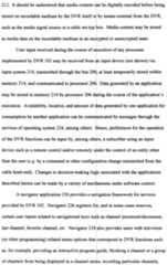
A conventional DVR may first record incoming media content to a time-shift buffer, and if desired, this media content may then be stored to a more permanent linear recording. However, using conventional designs, recording media content to the time-shift buffer before storing the media content to the more permanent linear recording can introduce problems affecting the user experience. For example, in the case of consecutively recorded (i.e., back-to-back) linear recordings, the second of the recordings may lose a portion of the beginning of the desired content. Specifically, according to conventional DVR designs, the time-shift buffer is stopped and restarted (i.e. which can include flushing the recorded media content out of the buffer) in between scheduled recordings. One potential effect of this is that, if a second tuner (which may have its own associated time-shift buffer) is not available to service the second of the back-to-back recordings, the second recording is delayed until the first recording finishes a conversion from the time-shift buffer to a permanent linear recording. Once the first of the back-to-back recordings finishes its conversion, the second recording may begin directing media content to the restarted time-shift buffer resource, which could be several seconds or minutes later (thus a portion of the beginning of the second requested media content is lost).
Additionally, regardless of whether linear recordings are first stored to a time- shift buffer, conventional DVRs are configured to reset the time-shift buffers when service contexts are attached and/or detached. Such service contexts are, for example, the main output for display and/or a PIP display. Accordingly, actions such as channel changes or picture-in-picture (PIP) swaps may cause media content previously recorded to a particular time-shift buffer associated with the service context to be discarded. Thus, if a user channel surfs from a first channel to a second channel, the buffer associated with the first channel is reset and the second channel begins using a fresh time-shift buffer. Thus, as a consequence, the user cannot rewind through media content previously recorded to the time-shift buffer while viewing the first channel. This is true even if the user switches back to the first channel. Similarly, if a PIP display includes a first channel as the main display and a second channel as the PIP, any content previously saved to a time-shift buffer associated within the main or PIP displays may be discarded and no longer accessible after swapping between the main and PIP display.
Accordingly, it is desirable to provide a media recording device that can be configured to mitigate these potential deficiencies, among others.
BRIEF DESCRIPTION OF THE DRAWINGS
The components in the drawings are not necessarily to scale relative to each other. Like reference numerals designate corresponding parts throughout the several views.
FIG. 1 depicts a block diagram of an arrangement of a digital video recorder (DVR) in accordance with embodiments of the present disclosure.
FIG. 2 depicts a block diagram of selected system components of an exemplary embodiment of the DVR of FIG. 1 FIG. 3 depicts a simplified block diagram illustrating an embodiment of the
DVR of FIG. 2 and depicting exemplary internal data paths for recording to a time- shift buffer, playing from a time-shift buffer, and/or converting from a time-shift buffer to a linear recording.
FIG. 4 depicts a graphical user interface of an exemplary program guide that can be displayed by a UI manager application 232 of the DVR of FIG. 2.
FIG. 5 depicts a buffer content diagram depicting the contents of an exemplary time shift buffer of the DVR of FIG. 2 with respect to time when recording back-to- back media content.
FIG. 6 depicts a diagram of the contents of exemplary linear recordings used to store media content converted from the time shift buffers of FIG. 5. FIG. 7 is a diagram depicting an exemplary composite timing diagram of the contents of the time shift buffer of FIG. 5 and the linear recording of FIG. 6.
FIG. 8 depicts a simplified diagram of the DVR FIG. 2 in a first exemplary picture-in picture (PIP) configuration. FIG. 9 depicts a simplified block diagram of the DVR of FIG. 2 in a second exemplary PIP configuration.
FIG. 10 depicts a simplified block diagram of the DVR of FIG. 2 in a third exemplary PIP configuration.
FIG. 11 depicts a representation of the contents of a first exemplary TSB of FIGs. 8 - 10 over a duration of time.
FIG. 12 depicts a representation of the contents of a second exemplary TSB of FIGs. 8 - 10 over a duration of time.
FIG. 13 depicts an exemplary simplified DVR configuration and resulting display at a time after a user first selects a first instance of media content to be displayed.
FIG. 14 depicts an exemplary second DVR configuration and resulting display at a time after a user selects a second instance of media content to be displayed.
FIG. 15 depicts an exemplary third DVR configuration and resulting display at a time after a user selects the first instance of media content again in order to be displayed.
FIG. 16 depicts a representation of the contents of an exemplary TSB of FIGs. 13 - 15 over a duration of time.
FIG. 17 depicts a representation of the contents of a second exemplary TSB of FIGs.13 - 15 over the duration of time. DETAILED DESCRIPTION
FIG. 1 depicts an embodiment of an arrangement 100 of a digital media recorder in accordance with embodiments of the present disclosure. According to embodiments described herein, the digital media recorder can be a digital video recorder (DVR) 102, which can be configured to Record video and/or audio, among other media types. However, according to some embodiments, the digital media recorder could be, among other devices used for recording media digitally, a personal video recorder (PVR), a personal digital recorder (PDR), a personal computer, laptop computer, or personal digital assistant (PDA) configured to execute media recording capabilities. Within the context of this document* media content may also be referred to herein as media programs or media programming and is intended to broadly refer to media in any of the various physical embodiment$, which could include, among others, stored or transmitted analog or digital signals. Additionally, reference may be made to media data, which is intended to specifically represent digitally encoded media content (i.e. audio signals, video signals, etc.).
According to some embodiments, DVR 102 may also be embedded within, or otherwise associated with, other electronic devices such as a cable television set-top box (STB), digital home communication terminal (DHCT), a tuner, a television, and/or a satellite-television receiver, among other$. DVR 102 can be configured to receive digital and/or analog media signals (i.e. signals representing media content, such as audio, video, and/or text, among other media formats) from a media signal source 104, and may also be in communication with a playback device, such as television 106. The playback device could also be a computer display, portable device, audio receiver, among other devices capable of emitting or displaying media. Media signal source 104 could be, but is ήpt limited to, a satellite television source, an over-the-air broadcast source, a cable-television (CATV) system, or could be a provider of signals received over a network (i.e. LAN., WAN, Internet, etc.) from a remote source. Thus, it can be appreciated that fnedia signal source 104 could be any of a number of sources of analog or digital media signals, such as video and/or audio signals that represent media content. Medi^ signal source 104 can also transmit additional network data, including Internet traffic^ teletext, closed-captioning, and programming guide information, among others. Media signal source 104 can transmit such signals over a communication channel 110 to DVR 102, which may be located at a customer premises 108. Although only one media signal source is depicted, it can be appreciated that DVR 102 cou^d also accept media signals from more than one media signal source. For example^ some embodiments of DVR 102 are capable of receiving signals from a CATV system as well as from an over-the-air transmitter. Television 106 can, for example, receive φid emit signals from DVR 102 representing the recorded (or non-recorded) medial content. For example, television 106 may be capable of emitting the media content) received by DVR 102. In some embodiments, television 106 is also used for dispjaying information associated with a graphical user interface generated by DVR 102. FIG. 2 is a block diagram depicting selected system components of an exemplary embodiment of the DVR 102 of FIG. 1. Omitted from FIG. 2 are a number of conventional components, known to those skilled in the art, that are unnecessary to explain the operation of the disclosed systems and methods.
FIG. 2 depicts several components commonly communicating through a local bus 200. For example, DVR 102 may include a communications interface 202 for receiving video, audio and other media signals from media signal source 104 (FIG. 1). Communications interface 202 can comprise, for example, an Ethernet interface, an
IEEE-1394 interface, a USB (Universal Serial Bu: ») interface, a serial interface, a parallel interface, a wireless radio frequency (RF) interface, a telephone line interface, a power line interface, a coaxial cable interface, ai id/or an infrared (IR) interface, among others.
DVR 102 also includes a tuner system 204 which could include, for example, a tuner for receiving and/or selecting one or more selected channels or digital streams of media signals. Tuner system 204 could comprise one or more tuner resources (not depicted). Such tuner resources may be broadly referred to herein as tuners. It should be understood that, in some instances, tuner system 204 can include one or more tuners configured for receiving analog media signals, while in some embodiments, tuner system 204 is configured with one or more tuners configured for receiving digital media signals. In some instances, tuner sy: ;tem 204 could even be configured with one or more tuners configured to receive boti analog and digital media signals. For example, in one instance, a first tuner of tuning system 204 receives an analog video signal corresponding to a first media content instance and a second tuner of tuner system 204 receives a digital compressed stream corresponding to a second media content instance.
DVR 102 can further include at least one processor 206 for controlling the operations of the DVR 102 and an output system 208 for driving a playback device (e.g., television 106). An input system 210 can re ceive user inputs provided via a wired or wireless input device such as, for examp e, a hand-held remote control, a transmitter with buttons or keys located on the exi erior of the DVR, and/or a keyboard.
 playback of recorded shows, etc.. Under user instruction, DVR application 228 can perform the general tasks of recording and/or and playing back received progKims, among other functions. Applications, such as navigator 226 and DVR application 228, can utilize services provided by user interface (UI) manager 232 and/or other graphics utilities provided by operating system 224 to draw dialog boxes, menus, graphics, etc. for display on playback device 106. UI manager 232, according to some embodiments, uses window management and graphics utilities provided by tho operating system 224 for presenting a user interface {i.e. through television 106). According to some embodiments, UI manager 232 may co-operate with the operating system 224 to allocate screen areas and managing screen use among the various applications. Accordingly, UI manager 232 can provide the user interface for the DVR. Accordingly, UI manager 232 may, for example, be directed by DVR application 228 to display information regarding the selection and/or input related to the residual time- buffering systems and methods describer herein.


The applications executed by DVR 102 cab comprise executable instructions for implementing logical functions. The applications can be embodied in any computer-readable medium for use by or in conne :tion with an instruction execution system. The instruction execution system may be for example, a computer-based system, a processor-containing system, or any othe ϊrr system capable of executing or interpreting instructions. In the context of this do ;ument, a "computer-readable medium" can be any means that can contain, store , communicate, propagate, or transport the program for use by or in connection With the instruction execution system, apparatus, or device.
The computer-readable medium can be, for example, but is not limited to, an electronic, solid-state, magnetic, optical, electromagnetic, infrared, or semiconductor Application No. 2003/0108331, which is incorporated by reference herein in its entirety. Among other potential benefits, such methodology provides a more desirable user experience in comparison to directing media content directly from a tuner into a linear recording.

According to some conventional designs, ii DVR scheduler is used to trigger stop/start recording events at the start and end time of each scheduled recording. These events are separate from a DVR recorder application which receives these events and allocates the necessary resources (i.e. tuner, TSB), directs the tuner to tune to a desired channel and/or stream, begins the TSB recording, and initiates the conversion process. At the end time of the scheduled recording, the recorder application finalizes the conversion process, waits for the conversion to complete, stops the TSB recording, releases the tuner and TSB resources, then notifies the scheduler that the recording is complete. This noi ification of the completion of the recording indicates to the scheduler that the tuner and/or TSB resources are available for pending scheduled recordings.
However, in the case of embodiments of rέsidual time-shift buffering described herein, DVR recorder application and/o r DVR scheduling application (the functions of which may be implemented by one or the other of DVR application 228 and operating system 230) can be configured such that media content continues to be directed to a TSB through its respective tuner even after a linear recording is complete or a service context is no longer associated with the TSB, such as if a user tunes to another channel. This can be advantageous in instances in which, for example, among other situations, another scheduled recording happens to begin on the same channel immediately after the first of a back-to-back recording or if the user decides to return to that channel for viewing after a channel change or PIP swap. According to such a residual time-shift buffering design, according to ! ome embodiments, the DVR scheduler need not be aware of the actual resource s, such as the tuners and/or TSBs, used to complete the recordings.
FIG. 3 depicts a simplified block diagram 300 of an embodiment of the DVR 102 of FIG. 2 which can be used to describe the operation of a DVR having the above described operability and to assist in the descript ;iiøn of various embodiments of residual time-shift buffering that can be used to further enhance a user's experience with media devices designed to direct media data to a TSB. Thus, FIG. 3 depicts the general operation of a DVR that is configured to direct media content first through a TSB buffer 306 - 310, including media content to be recorded to a more permanent linear recording 318. For example, media conteni is delivered from media signal source 104 to DVR 102 over one or more communication channels 110. A tuner resource, such as tuners 302 and 304 of tuner syst m 204 are each configured to receive desired media content and provide the mejdia content to one of TSB 306, TSB 308, or TSB 310.
According to some embodiments TSBs 308 - 310 are logically created during a boot-up sequence of DVR 108. For example, thieir creation may include the allocation of space (i.e. memory locations) within a storage device, such as internal storage 218. Once created, TSBs 308 - 310 can fprm a logical pool of buffers that can be selected and associated with tuners 302 and 304 in order to store media content therein.
Although two tuners 302 and 304 are depi ;ted, DVR 102 may include any number of tuners. Likewise, although a pool of only three logical TSBs 308 - 310 are depicted, other embodiments may use more or les 5 buffers. However, according to some embodiments, a tuner is associated with onlV one of the TSBs in the pool of stored therein. However, in other embodiments, guide information or other information describing the media content are stored in other data files. In order to convert the portions of the media data stored to th ; TSB into a linear recording, a similar management file is created for the linear recording and the data clusters and related information previously found in the TSB are associated with the management file for the linear recording.

The time to start such a conversion operation can be configurable, or dictated by factors such as when a notification is received :hat such conversion is desired.
However, it should be understood that the conver. ion of any particular portion of the received media content in TSB 306 occurs before the media content desired to be stored as linear recording 318 is overwritten by in :oming media content in TSB 306. Typically, especially for scheduled recordings, the media content is converted relatively soon after being stored to the TSB 306. It is not necessary for a scheduled recording to be stored into a TSB in its entirety bdfore beginning such a conversion process. Rather, portions of media content can be converted to the linear recording as soon as it is stored within the TSB.
Although only one linear recording 318 is depicted, it should be understood that any of the available TSBs can be used for a li iear buffer conversion, and these conversions could even be performed simultaneoi sly (or substantially simultaneously). Additionally, depending on available storage space, any number of desired linear recordings can be stored for an inde inite length of time.
One potential side-effect of recording permanent recordings through a circular- buffer conversion, however, is that the conversion process introduces a latency between the time that a portion of media content i 3 received and the time that that the portion of media content finishes conversion from the TSB to the linear recording. Depending on a number of factors, such as the amount of media content to be converted, among other factors, the process of performing this conversion can be time consuming.
Accordingly, even if the conversion is being performed substantially in real- time as the media content is received into the TSE , there can be a delay of several seconds between the time that a portion of media content is first stored to the TSB and the time that the portion of media content is converted into the linear recording. The latency between when a portion of media content s first stored to the TSB and when that portion of media content is converted into the linear recording is described in more detail with respect to FIGs. 4 - 7.
Although certain embodiments of FIG. 3 have been described as directing media content through a service context and/or to a linear recording through a TSB, some embodiments could route media content fron one of the tuners 302, 304 directly into a linear recording and/or service context. In 1his respect, it should be understood that the simplified block diagram of FIG. 3 is non limiting and depicts only examples of possible paths for media content.
FIG. 4 is a graphical user interface (GUI) 400 depicting an exemplary program guide that can be displayed by the UI manager application 232 of DVR 102. GUI 400 can display media content such as television prog: ling, along with its associated show times, dates, and related information. Among other potential uses, GUI 400 can be used by a user to select a channel in order to vi sw live television on that channel through the TSB or to select media content to be recorded, more permanently, to a linear recording.
As depicted, the television show "RAYMOND" is available (e.g., via download or broadcast) from 8:00 PM until 8:30 'M on channel 2. Likewise, the television show "FRIENDS" is available from 8:3 0 PM to 9:00 PM on channel 2. Accordingly, the shows RAYMOND and FRIENDS are made available consecutively on the same channel. That is, according to this example, no other media content is to be received between RAYMOND and FRIENDS >n channel 2. As indicated by the depicted star-shaped icons, RAYMOND and FRIENDS have been selected by a user as being scheduled to be recorded into a permanent recording.
Thus, with reference back to FIG. 3, at or before 8:00 PM an available tuner 302 or 304 of DVR 102 will tune to channel 2 in order to begin directing media content associated with the television show RAYI 4OND to one of the available TSBs 306 - 310. At a time before media content associated with the television show
RAYMOND is overwritten by other incoming meldia content in the selected TSB, the media content is converted into a linear recording such as linear recording 318. A similar procedure is used to record the show FRIENDS into a linear recording.
FIG. 5 depicts a buffer-content diagram 5C0 depicting the contents of a TSB with respect to time when recording back-to-back media content. Specifically, diagram 500 depicts instances of media content, RAYMOND 502 and FRIENDS 504, being consecutively recorded to a TSB, such as TSB 306, along time dimension 506. Although diagram 500 depicts only media instanc :s RAYMOND 502 and FRIENDS 504, other previously or later stored media conten that has not been overwritten may also exist within the same TSB.
At time 510, a user changes the channel to channel 1 , causing an available tuner to begin to receive media content on channe 1. Accordingly, at this time, media content appearing on channel 1 is directed from a [first tuner to a first TSB. This action is not shown in FIG. 5. However, with refdrence to FIG. 3, tuner 302 can be used to receive the media content on channel 1 and direct the media content into TSB 308, for example. The media content received on channel 1 can then be displayed via an associated service context 316, which could be a display output of a television. At time 512, media instances RAYMOND 502 and FRIENDS 504 are selected by a user for recording into a linear recording. Fo• example, as described previously, the user may select desired media instances (i.e., I LAYMOND and FRIENDS) to be stored into a linear recording using the guide depi :ted in the GUI 400 of FIG. 4. At time 514, which could be 8:00 PM as s iown in the guide of FIG. 5, DVR application 228 determines whether a tuner resouilce is available to record the media instance RAYMOND 502 as scheduled at time 512. For example, the exemplary
DVR 102 of FIG. 3 includes dual tuners 302 and _ 04, allowing the instance of media content, RAYMOND 502, to be received, directed to a TSB and converted to a linear recording while the user simultaneously watches 4esired live media content, such as DEAL OR NO DEAL, on channel 1. However, in the case that DVR 102 includes only a single tuner, DVR 102 acquires the tuner re source currently being used to receive the media content on channel 1 in order to allow RAYMOND 502 to be received on channel 2, directed to an available TSp, and stored into the linear recording as scheduled.
However, according to the present embodiment, it is assumed that a second tuner is available. Here, in this case, again referring back to FIG. 3, if tuner 302 is used for receiving live media content (e.g. DEAL OR NO DEAL) on tuner 302, tuner 304 can be used for the purposes of receiving RAYMOND 502. Thus, at time 514, RAYMOND 502 is received through the tuner 304 and begins to be directed into TSB 306. Additionally, also at time 514, the media instance conversion of RAYMOND 502 into a more permanent linear recording can commence. It should be understood that, in some instances, the conversion could be started at a later time, even at a time after the entire media content instance of RAYMOND 502 has been stored to TSB 306.
According to some embodiments, the reco ding of RAYMOND 502 can be performed without directing media content in the FSB 306 to a service context. In this case, no service context is associated with TS[B 306. Such a recording may be referred to herein as a background recording, However, in another embodiment, service context 316 corresponds to a main display on television 106 and service context 314 represents a PIP within the main disp ay, allowing the user to view the media content received on channel 1 (via tuner 3C22 and TSB 308) on the main display through service context 316 and view the media content from channel 2 (via tuner 304 and TSB 306) in the PIP display through service c ontext 314. Looking back to FIG. 5, at time 516, the media instance RAYMOND 502 has been completely stored into the TSB. Unlike con entional approaches, however, in that the second instance of media content, FRJEN )S 504, occurs directly after RAYMOND 502, DVR 102 is configured to cont: nue directing media content from the second tuner into TSB 306 for at least a prede ermined duration of time, without flushing or resetting TSB 306.
FIG. 6 depicts a diagram 600 depicting the contents of exemplary linear recordings used to store media content converted τom a TSB with respect to time, For example, FIG. 6 depicts a linear recording 60: of RAYMOND as converted from the media instance RAYMOND 502 in the TSB o FIG. 5, and linear recording 604 containing the media content instance FRIENDS is converted from FRIENDS 504 in the TSB of FIG. 5.
As discussed above, the process of conver ing the media content from a TSB into a linear recording takes a period of time. Thus >, although the instance of media content RAYMOND 502 may begin the linear redord liinngg i conversion at time 514, corresponding converted media content received ∑ t time 514 is not converted and stored into the linear recording of RAYMOND 602 until time 606, which could be several seconds or minutes later, for example. LiI :ewise, despite that RAYMOND 502 may have finished being directed into the TSB at time 516, the end of the conversion process does not occur until after time 516 (e.g., at time 608) . FIG. 7, described below, better illustrates the delay between the start and end of conversion of a portion of an instance of media content.
Specifically, FIG. 7 is a composite timing diagram 700 depicting the contents of the TSB 306 of diagram 500 and the linear recordings of diagram 600. Notably, a duration of time 702 exists between the time 516 hat media instance RAYMOND
502 (FIG. 5) has been completely stored into the respective TSB and the time 608 that RAYMOND 602 (FIG. 6) has been converted from the TSB into the linear recording.
According to conventional designs, at the ϊnd of conversion when the first linear recording is considered complete, the TSB resource used to temporarily hold RAYMOND 502 for the linear recording is stopped and released resulting in any previously buffered content being flushed from the TSB if the associated channel is not currently selected for viewing by the end user (i.e., a background recording) so that the TSB resource may be made available for buffering and possibly converting subsequent instances of media content to a linear recording captured from the same or different tuner associated with the TSB. Unfortur ately, such a design has negative consequences for recording the next instance of media content FRIENDS 504 which appears subsequent to RAYMOND 502 on the same channel. Specifically, any portion of the next instance of media content FRIENDS 504 directed into the TSB while the conversion of RAYMOND 502 into RAYMOND 602 is in progress cannot be used for the conversion of FRIENDS 504 into I7RIENDS 604 because the contents of the TSB are flushed after the conversion of RAYMOND 502 into RAYMOND 602 is complete. Further, according to conventional d ;signs, a new TSB resource cannot be assigned to the tuner associated with said TSB until the conversion of RAYMOND
502 into RAYMOND 602 is complete or cancelle I prior to completion. Therefore, only the portion of the media content instance FR ENDS 504 directed into a newly established TSB session (e.g., using TSB 306), which started after the conversion of RAYMOND 502 completes, is available for conversion. In other words, a portion of the media content instance FRIENDS 504 that coi responds to at least the length of the duration of time 702 is not stored to any TSB at tl e time the conversion is initiated, and therefore is also unable to be converted to the linear recording of FRIENDS 604.
However, using residual time buffering embodiments described herein, media data continues to be directed through tuner 304 in o the same TSB 306 used to store the first media content instance RAYMOND 502 for at least a predetermined duration of time. As will be explained in more detail below, such behavior proves beneficial, for example, when another recording of an instanc :e of media content starts directly after the prior recording (i.e. a back-to-back recon ling) or if the user surfs to the channel being buffered (residually) for viewing.
According to some instances, the predetennined duration that the media content continues to be directed into TSB 306 is at least as long as the duration 702, which is the time period extending between the time that the second media instance
FRIENDS 504 begins being directed into the TSB; and the time that the first media instance RAYMOND 502 finishes its conversion nto the linear recording.
According to some embodiments, the predetermined duration could be set to other values, which may be, among others, precon figured, configurable by a user setting, or configurable by a multiple-service operator (MSO). It can be advantageous in some embodiments to use the predetermined duration as opposed to allowing media data to continue to be directed into the buffer indefinitely. For example, allowing media data to be directed into the buffer indefinitely can affect power-saving functionality and/or wear-and-tear to storage devices used for the TSB. Accordingly, one potential benefit for residual time-shift buffering, according to the embodiments of FIGs. 5 -7, is allowing the second scheduled recording of the back-to-back recordings being received on the same channel or stream to be performed using the same TSB. This is in contrast to conventional approaches of stopping and restarting a TSB in between the bad -to-back recordings, which can result in undesirable content loss at the beginning of the second recording.
The same principles used above that continue to direct a media content into a TSB after the end of a recording can, in some embodiments, also be advantageously applied to PIP swapping and channel changing.
For example, FIGs. 8 - 10 depict simplify . block diagrams of DVR 102 in various exemplary PIP configurations. Each of FI]Gs. 8-10 depict an associated display within television 106 that is perceived by k user based on the selected PIP configuration. In each of FIGs 8 — 10, media contlent that is received through tuners
304 and 306 is directed into respective TSBs 306 ind 308. Specifically, an instance of media content received by tuner 304 represents vi leo of a dog, and an instance of media content received by tuner 302 represents a ' ideo of a boat. Accordingly, in each of FIGs. 8 - 10, tuner 304 directs media cont ent representing the dog into TSB
306, while tuner 302 directs media content representing the boat into TSB 306. FIG.
11 depicts a representation of the contents of TSB 306 of FIGs 8 - 10 over a duration of time 1102. Similarly, FIG. 12 depicts a representation of the contents of TSB 308 of FIGs 8 - 10 over the duration of time 1102. FIG. 8 depicts a first exemplary DVR configuration 800 when service context 314 (a main display 314a of television 106) is associated with TSB 306, and service context 316 (PIP display 316a of television 106) i associated with TSB 308. For example, this could be the configuration at time 1 02 of FIGs. 11 and 12. FIG. 9 depicts a second exemplary DVR configuration 9(1O in which service context 314 is associated with TSB 306 and service context 316 s associated with TSB 308. For example, this could be the configuration at time 1104 of FIGs. 11 and 12.
Accordingly, the swapping of service contents depicted in the change from configuration 800 to configuration 900 may be referred to as a PIP swap. Notably, despite that the service context attached to each T SB 306 and 308 is swapped at time
1104, the video of the dog received through tuner 304 continues to be directed to TSB
306 and the video of the boat received through tuner 302 continues to be directed to
TSB 308. Specifically, according to some embod ments, the video of the dog received through tuner 304 continues to be directed to TSB 306 for at least a predetermined duration of time 1106. Thus, the predetermined duration of time 1106 can be defined by the time period beginning at the time that the P P swap occurs (e.g. time 1104) and ending at time 1108. According to some embodiments , the predetermined duration 1106 can be, among others, preconfigured, config urabl e by a user setting, or configurable by a multiple-service operator (MSO . It can be advantageous in some embodiments to provide such a value for the predetermined duration as opposed to allowing media data to continue to be directed into the buffer indefinitely. For example, allowing media data to be directed into the TSB indefinitely can negatively affect power-saving operations of DVR 102 and/o wear-and-tear to storage devices used for the TSB 306. Once ending time 1108 of duration 1106 ii reached, the TSB 306 can be configured to stop buffering content from tuner 304 unless other conditions are met. For example, such a condition that buffering should continue is the case that TSB 306 is attached to a service context at the ending time 1108. Thus, according to such an embodiment, assuming that a subsequent PIP swap occurs at a time within the duration 1106, a user is advantageously able to access media content buffered within
TSB 306. For example, at time 1110, a user may switch back to the configuration 800 of FIG. 8 to view the video of the dog stored in T$B 306 within the main display 314a of television 106 and viewing the video of the bo; in TSB 308 within the PIP display 316a. Accordingly, similar to the embodiment described above, DVR 102 continues to direct the video of the boat into TSB 308 for at least a predetermined duration of time 1112, having a beginning time corresponding to the time of the second PIP swap 1110 and ending at time 1114.
However, FIG. 10 illustrates a third exemj lary DVR configuration 1000 in which service context 314 is associated with TSB 306 and service context 316 is no longer associated with a TSB at all. This configuration can occur, for example, if the user instructs DVR to remove PIP display 316a from the television 106 in order to view the video of the dog without the overlay of FIP display 316a. For example, configuration 1000 is selected at time 1116 of FIC s. 11 and 12. According to one embodiment, DVR 102 determines at time 1114 ( he end of predetermined duration
1112) that no service context is attached to buffer 308. Thus, media content from tuner 302 no longer continues to be directed to TSB 308 at time 1114, although media content from tuner 304 continues to be directed into TSB 306 for display within service context 314a. In addition to the swapping between a maib display and the PIP display, residual time-shift buffering can also be beneficia in instances in which the user turns the PIP display off, then turns PIP display back or before the predetermined duration is over. Another instance where residual time-shift buffering can improve the user's experience is in instances in which the user turns3IP display off, then surfs to the channel or stream previously being displayed in the PIP display, before the predetermined duration is over. In both cases, the media data in the respective TSB for the initial PIP display is preserved, and the buiϊered media content remains available to the user (e.g. for playback, recording, etc.). Although the embodiments of FIGs. 8 - K are depicted and described as routing all media content through a TSB, this is rrrnerely one embodiment. According to some embodiments, media content is directed t) at least one service context directly from the tuner, bypassing the TSB. Additionally, in some embodiments, a user may be viewing previously recorded content from a Hn ear recording in a first service context while viewing content received at one of tuners 302, 304 in a second service context. As a non-limiting example, a user may view a baseball game through tuner 304 and TSB 306 in the PIP display (e.g. service context 316), while viewing pre- recorded content from a linear recording in the m«in display (e.g. service context 314). Similar residual time-shift buffer principl es described above for use with back- to-back recordings and PIP swapping can also be jeneficially applied to channel changes. For example, FIGs. 13 - 15 depict simp ified block diagrams of DVR 102 in various exemplary channel configurations. Each )f FIGs. 13 - 15 also depict an associated display within television 106 that is perceived by a user based on the channel configuration. FIG. 16 depicts an exemp! ary representation of the contents of TSB 306 of FIGs. 13 - 15 over a duration of time 1602. Similarly, FIG. 17 depicts a representation of the contents of TSB 308 of FIGs 13 - 15 over the duration of time
1602.
Looking specifically to FIG. 13, a first D'. VR . configuration 1300 is depicted at a time after a user first selects a first instance of njed liiaa c i ontent to be displayed within television 106. For example, a user may select mέdia content, which could, for example, correspond to a television show from th channel guide displayed by the
DVR 102 in FIG. 2. The selected media content ( an correspond media content transmitted on a first channel tuned by tuner 304. Here, the media content received at tuner 304 is a video of a dog. The video of the dog is received by tuner 304 and directed into TSB 306. Service context 314, whidh corresponds to the main display 314a of television 106 is then associated with TS$ 306. At this time, tuner 302, TSB
308, and service context 316 are unused. A user may select configuration 1300 at time 1602 (FIGs. 16 and 17). As shown, TSB 301 ! (FIG. 17) remains empty at time 1602, while TSB 306 (FIG. 16) begins to store th< video of the dog at time 1602.
FIG. 14 depicts a second DVR configurati •n 1400 at a time after a user selects a second instance of media content to be displayed within television 106, such as when a user changes the channel. For example, a user may select different media content {e.g. a different television show) from a c iannel guide displayed by the DVR 102. Here, the selected media content received at tuner 302 is a video of a boat. The video of the boat is received by tuner 302 and begins to be directed into TSB 308. Service context 314 is disassociated with TSB 306 and associated with TSB 308.
Although the service context association has been changed, TSB 306 continues to receive the video of the dog directed from tuner 304 for at least a predetermined duration of time. For example, this service contentt re-association occurs at time 1604 of FIGs. 16 and 17, and the predetermined duration of time can be represented by duration 1606.
FIG. 15 depicts a third DVR configuration 1500 at a time after a user, once again, selects the first instance of media content (the video of the dog) to be displayed within television 106. For example, a user may return to viewing the instance of media content previously viewed in configuration 1300 of FIG. 13.
According to one embodiment, the user re urns to viewing the video of the dog before the end of the predetermined duration of time 1606. For example, looking to
FIGs. 16 and 17, the user can return to viewing th ϊ first instance of media content at time 1610, which occurs before the end of duration 1606 (marked by time 1608). In this case, at time 1610, service context 314 is disassociated with TSB 308 and re- associated with TSB 308. Accordingly, the user i able to view any content previously recorded to TSB 306, including the content directed to TSB 306 while the user viewed content from TSB 308.
As with the PIP embodiments described above, in some embodiments, because there is an active service context associated with SB 306, media content continues to be directed to TSB 306 even after the end of predetermined duration 1606. However, if there is no service context associated with the 1 SB at the end of the predetermined duration, media content is no longer directed into the TSB. For example, looking to FIG. 17, the predetermined duration 1612 extends through time 1614. However, no service context is associated with buffer 308 at tir ie 1614. Accordingly, DVR 102 stops directing media content into TSB 308, resets the TSB 308 and returns it to the pool of available TSBs. As a consequence, if the channel tuned by tuner 308 is selected again, only media content received after tjhe DVR 102 re-tunes to this channel is available for viewing. and/or which channel was viewed last, among oth r possibilities. Thus, according to the example above, if the resources to be freed an determined based on the length of time spent viewing the particular channels, one embodiment may free the tuner/TSB used to record content on channel B since channe B was viewed for less time than channel A (perhaps indicating that a user is less ii :erested in the media content on channel B in comparison to the content on channc A). However, if the resources to be freed are determined based on which channel ψas viewed last, the tuner/TSB used to record content on channel A can be freed for viewing the contents on the selected channel C. Such an embodiment may presume that a user is more likely to switch back to the channel having the most previously vi wed media content. According to some embodiments, the policy could be user conf gurable or remotely configurable (e.g. under instructions received by the cable heac -end or other remote server),

Conditional language, such as, among oth is, "can," "could," "might," or "may," unless specifically stated otherwise, or oth erwise understood within the context as used, is generally intended to convey that certain embodiments, among others, include, but do not require, certain feature , elements and/or steps. Thus, such conditional language is not generally intended to mply that features, elements and/or steps are in any way required for one or more embodiments or that one or more embodiments necessarily include logic for decidirfg ;, with or without user input or prompting, whether these features, elements and/ r steps are included or are to be performed in any particular embodiment.
Any process descriptions, steps, or blocks n the flow diagrams described herein and/or depicted in the attached figures sho Id be understood as potentially representing modules, segments, or portions ofco ie which include one or more executable instructions for implementing specific ogical functions or steps in the process. Alternate implementations are included within the scope of the preferred embodiments of the systems and methods describϊd herein in which steps or functions may be deleted, executed out of order from that shown or discussed, including substantially concurrently or in reverse order, depending on the functionality involved, as would be understood by those reasonably skilh d in the art. It should be emphasized that many variati >ns and modifications may be made to the above-described embodiments. All such modifications and variations are intended to be included herein within the scope o: this disclosure and protected by the following claims.
Claims
CLAIMS At least the following is claimed: 1. A method for managing time-shift buffering in a digital media recording device, comprising: receiving media content through at least a first tuner of the digital media recording device, the media content comprising ai least a first instance of media content received consecutive to a second instance of media content; directing the first instance of media content into a first time-shift buffer, the first instance of the media content received throuj ;h the first tuner of the digital media recording device; and after directing the first instance of the mec ia content into the first time-shift buffer, directing the second instance of media cor tent into one of the first time-shift buffer and a second time-shift buffer while continuing to direct media content received through the first tuner of the digital med a recording device into the first time-shift buffer for at least a predetermined dura ion of time.
2. The method of claim 1 , wherein the first ii istance of media content and the second instance of media content are received cor secutively through the first tuner, the first instance of media content and the second instance of media content being sequentially directed into the first time-shift buffejr from the first tuner, the method further comprising: converting at least a portion of the first instance of media content directed to the first time-shift buffer into a linear recording ai a time when directing a portion of the second media instance received through the fi: st tuner of the digital media recording device into the first time-shift buffer.
3. The method of claim 2, further comprising: converting the second media instance directed to the first time-shift buffer into a linear recording at a time after converting the first media instance into a linear recording.
4. The method of claim 3, wherein the predetermined duration that the media content continues to be directed into the first buff T is at least as long as the time period extending between the time that the second media instance begins being directed into the time-shift buffer and the time that the first media instance finishes conversion into the linear recording.
5. The method of claim 1, further comprising determining whether a tuner resource is available at a designated time in order to direct the second instance of media content intώ one of the first time-shift buffer and the second time-shift buffer while continuing to direct media content received through the first tuner of the digital media recording device into the first time-shift buffer for at least the predetermined duration of time, the designated time being substantially the same time that the first media instance has finished being directed into the first time-shift buffer.
6. The method of claim 5, further comprising: after the predetermined duration, discontir uing the direction of the media content received through the first tuner of the digital media recording device into the first time-shift buffer.
7. The method of claim 6, further comprising;: attaching a first service context to the first time-shift buffer; detaching the first service context from the first time-shift buffer upon determining that the tuner resource is available; and reattaching the first service context to the lrst time-shift buffer before the predetermined duration has elapsed.
8. The method of claim 6, wherein the step o|f directing the second instance of media content into one of the first time-shift buffiέr and the second time-shift buffer while continuing to direct media content received through the first tuner of the digital media recording device into the first time-shift buffer for the predetermined time comprises directing the second instance of media content into the second time-shift buffer through a second tuner, and the method further comprises: attaching a first service context to the first time-shift buffer; attaching a second service context to the s ;cond time-shift buffer; detaching the first service context from th first time-shift buffer and detaching the second service context from the second time-5 hift buffer; and attaching the second service context to the first time-shift buffer before the predetermined duration has elapsed.
9. The method of claim 6, wherein discontin iing the direction of the media content received through the first tuner of the digital media recording device into the first time-shift buffer after the predetermined dimtion is performed if the first time- shift buffer is not used for directing media conten ; to a linear recording or service context at the end of the predetermined duration.
10. The method of claim 1 , wherein the step o directing the second instance of media content into one of the first time-shift buffetr and the second time-shift buffer while continuing to direct media content received through the first tuner of the digital media recording device into the first time-shift buffi :er for the predetermined time comprises directing the second instance of media ontent into the second time-shift buffer through a second tuner, and the method further compπses: attaching a service context to the first ttiimej-shift buffer; detaching the service context from the firs time-shift buffer; and attaching the service context to the second! time -shift buffer.
11. The method of claim 9, further comprising: detaching the service context from the seo >nd time-shift buffer; and reattaching the service context to the first 1 ime-shift buffer before the predetermined duration has elapsed.
12. A digital media recording device comprising: a memory for storing logic; and processing circuitry configured to execute the logic, the logic configured for: receiving media content through ai least a first tuner of the digital media recording device, the media conteni comprising at least a first instance of media content received consecutive to second instance of media content; directing the first instance of medi i content into a first time-shift buffer, the first instance of the media cont ;nt received through the first tuner of the digital media recording device; and after directing the first instance of the media content into the first time- shift buffer, directing the second instance )f media content into one of the first time-shift buffer and a second time-shift buffer while continuing to direct media content received through the first tvner of the digital media recording device into the first time-shift buffer for ai least a predetermined duration of time.
13. The digital media recording device of claijn 12, wherein the first instance of media content and the second instance of media cbntent are received consecutively through the first tuner, the first instance of media content and the second instance of media content being sequentially directed into the first time-shift buffer from the first tuner, wherein the logic further comprises logic configured for: converting at least a portion of the first ins tance of media content directed to the first time-shift buffer into a linear recording ai a time when directing a portion of the second media instance received through the fi st tuner of the digital media recording device into the first time-shift buffer.
14. The digital media recording device of claitn 13, wherein the logic further comprises logic configured for: converting the second media instance directed to the first time-shift buffer into a linear recording at a time after converting the fhjst media instance into a linear recording.
15. The digital media recording device of claii n 14, wherein the predetermined duration that the media content continues to be directed into the first buffer is at least as long as the time period extending between the ilime that the second media instance begins being directed into the time-shift buffer anil the time that the first media instance finishes conversion into the linear recording.
16. The digital media recording device of claijn 12, wherein the logic further comprises logic configured for: determining whether a tuner resource is available at a designated time in order to direct the second instance of media content intc one of the first time-shift buffer and the second time-shift buffer while continuing to direct media content received through the first tuner of the digital media recordi ng device into the first time-shift buffer for at least the predetermined duration of time, the designated time being substantially the same time that the first media in: tance has finished being directed into the first time-shift buffer.
17. The digital media recording device of claipi 16, wherein the logic further comprises logic configured for: after the predetermined duration, discontinuing the direction of the media content received through the first tuner of the digital media recording device into the first time-shift buffer.
18. The digital media recording device of claύjn 17, wherein the logic further comprises logic configured for: attaching a first service context to the first time-shift buffer; detaching the first service context from the first time-shift buffer upon determining that the tuner resource is available; and reattaching the first service context to the ϊrst time-shift buffer before the predetermined duration has elapsed.
19. The digital media recording device of claii n 17, wherein the logic for directing the second instance of media content into one of the first time-shift buffer and the second time-shift buffer while continuing to direc media content received through the first tuner of the digital media recording device into the first time-shift buffer for the predetermined time comprises logic for directing lie second instance of media content into the second time-shift buffer through a second, tuner, and wherein the logic further comprises logic configured for: attaching a first service context to the first time-shift buffer; attaching a second service context to the s ϊcond time-shift buffer; detaching the first service context from the first time-shift buffer and detaching the second service context from the second time-s hift buffer; and attaching the second service context to the first time-shift buffer before the predetermined duration has elapsed.
20. The digital media recording device of claiin 17, wherein the logic configured to discontinue the direction of the media content leceived through the first tuner of the digital media recording device into the first time-: ihift buffer after the predetermined duration is performed if the first time-shift buffer is not used for directing media content to a linear recording or service context at jthe end of the predetermined duration.
21. The digital media recording device of claijn 12, wherein the logic for directing the second instance of media content into one of t tie first time-shift buffer and the second time-shift buffer while continuing to direc media content received through the first tuner of the digital media recording device into the first time-shift buffer for the predetermined time comprises logic for directing the second instance of media content into the second time-shift buffer through a second. tuner, and the logic further comprises logic configured for: attaching a service context to the first time -shift buffer; detaching the service context from the first time-shift buffer; and attaching the service context to the seconc time-shift buffer.
22. The digital media recording device of claijn 20, wherein the logic further comprises logic configured for: detaching the service context from the secbnd time-shift buffer; and reattaching the service context to the first ime-shift buffer before the predetermined duration has elapsed.
23. A digital media recording device, comprising: means for receiving media content through at least a first tuner of the digital media recording device, the media content compr sing at least a first instance of media content received consecutive to a second instance of media content; means for directing the first instance of m ϊdia content into a first time-shift buffer, the first instance of the media content rece ived through the first tuner of the digital media recording device; and means for, after directing the first instance of the media content into the first time-shift buffer, directing the second instance of media content into one of the first time-shift buffer and a second time-shift buffer w tiile continuing to direct media content received through the first tuner of the dig tal media recording device into the first time-shift buffer for at least a predetermined duration of time.
Priority Applications (2)
| Application Number | Priority Date | Filing Date | Title |
|---|---|---|---|
| CA2655663ACA2655663C (en) | 2006-06-29 | 2007-06-18 | Residual time-shift buffering in a digital media device |
| EP07798681.8AEP2033438B1 (en) | 2006-06-29 | 2007-06-18 | Residual time-shift buffering in a digital media device |
Applications Claiming Priority (2)
| Application Number | Priority Date | Filing Date | Title |
|---|---|---|---|
| US11/427,752 | 2006-06-29 | ||
| US11/427,752US7848613B2 (en) | 2006-06-29 | 2006-06-29 | Residual time-shift buffering in a digital media device |
Publications (1)
| Publication Number | Publication Date |
|---|---|
| WO2008002782A1true WO2008002782A1 (en) | 2008-01-03 |
Family
ID=38654578
Family Applications (1)
| Application Number | Title | Priority Date | Filing Date |
|---|---|---|---|
| PCT/US2007/071423WO2008002782A1 (en) | 2006-06-29 | 2007-06-18 | Residual time-shift buffering in a digital media device |
Country Status (4)
| Country | Link |
|---|---|
| US (1) | US7848613B2 (en) |
| EP (1) | EP2033438B1 (en) |
| CA (1) | CA2655663C (en) |
| WO (1) | WO2008002782A1 (en) |
Families Citing this family (12)
| Publication number | Priority date | Publication date | Assignee | Title |
|---|---|---|---|---|
| KR100768911B1 (en)* | 2006-07-25 | 2007-10-19 | 삼성전자주식회사 | Image recording method and time recording device for time shift function |
| US8660409B2 (en)* | 2009-05-01 | 2014-02-25 | International Business Machines Corporation | Predictive personal video recorder operation |
| CN103718543A (en)* | 2011-07-27 | 2014-04-09 | 汤姆逊许可公司 | Variable real time buffer and apparatus |
| US20130279877A1 (en)* | 2012-04-19 | 2013-10-24 | Qnx Software Systems Limited | System and Method Of Video Decoder Resource Sharing |
| GB2507764C (en) | 2012-11-08 | 2017-08-16 | Nds Ltd | Review buffer |
| US9980006B2 (en) | 2015-03-26 | 2018-05-22 | Opentv, Inc. | Systems and methods of recalling channels and review buffer management |
| US20160309227A1 (en)* | 2015-04-20 | 2016-10-20 | Echostar Technologies L.L.C. | Real-time recording timer adjustments and related methods, devices and systems |
| US10805668B2 (en)* | 2015-05-20 | 2020-10-13 | DISH Technologies L.L.C. | Apparatus, systems and methods for trick function viewing of media content |
| US10382815B2 (en) | 2015-10-15 | 2019-08-13 | DISH Technologies L.L.C. | Apparatus, systems and methods for buffering of media content |
| JP6701776B2 (en)* | 2016-02-15 | 2020-05-27 | 船井電機株式会社 | Recording device, recording method |
| TWI601421B (en)* | 2016-07-01 | 2017-10-01 | 物聯智慧科技(深圳)有限公司 | Cloud recording system, cloud recording server and cloud recording method |
| US10856038B2 (en) | 2018-08-23 | 2020-12-01 | Sling Media Pvt. Ltd. | Predictive time-shift buffering for live television |
Citations (4)
| Publication number | Priority date | Publication date | Assignee | Title |
|---|---|---|---|---|
| US20020199185A1 (en) | 2001-05-11 | 2002-12-26 | Kaminski Dariusz S. | Managing time shift buffers |
| US20030108331A1 (en)* | 2001-12-06 | 2003-06-12 | Plourde Harold J. | Converting time-shift buffering for personal video recording into permanent recordings |
| WO2005069612A1 (en)* | 2004-01-08 | 2005-07-28 | Koninklijke Philips Electronics, N.V. | Marking program boundaries in a personal video recording device |
| WO2006015186A2 (en) | 2004-07-30 | 2006-02-09 | Matsushita Electric Industrial Co., Ltd. | System and method for distributed sharing and recording of live-tv |
Family Cites Families (5)
| Publication number | Priority date | Publication date | Assignee | Title |
|---|---|---|---|---|
| US5438423C1 (en)* | 1993-06-25 | 2002-08-27 | Grass Valley Us Inc | Time warping for video viewing |
| JP2000184320A (en)* | 1998-12-11 | 2000-06-30 | Nec Corp | Recording and reproducing device and display device for electronic program guide |
| CA3011846C (en)* | 2001-02-21 | 2021-02-16 | Rovi Guides, Inc. | Systems and methods for interactive program guides with personal video recording features |
| US7260312B2 (en)* | 2001-03-05 | 2007-08-21 | Microsoft Corporation | Method and apparatus for storing content |
| US20050111819A1 (en)* | 2003-11-26 | 2005-05-26 | Cormack Christopher J. | System and method for allowing time-shifted access to multiple programs at the same time |
- 2006
- 2006-06-29USUS11/427,752patent/US7848613B2/enactiveActive
- 2007
- 2007-06-18WOPCT/US2007/071423patent/WO2008002782A1/enactiveApplication Filing
- 2007-06-18CACA2655663Apatent/CA2655663C/ennot_activeExpired - Fee Related
- 2007-06-18EPEP07798681.8Apatent/EP2033438B1/ennot_activeCeased
Patent Citations (4)
| Publication number | Priority date | Publication date | Assignee | Title |
|---|---|---|---|---|
| US20020199185A1 (en) | 2001-05-11 | 2002-12-26 | Kaminski Dariusz S. | Managing time shift buffers |
| US20030108331A1 (en)* | 2001-12-06 | 2003-06-12 | Plourde Harold J. | Converting time-shift buffering for personal video recording into permanent recordings |
| WO2005069612A1 (en)* | 2004-01-08 | 2005-07-28 | Koninklijke Philips Electronics, N.V. | Marking program boundaries in a personal video recording device |
| WO2006015186A2 (en) | 2004-07-30 | 2006-02-09 | Matsushita Electric Industrial Co., Ltd. | System and method for distributed sharing and recording of live-tv |
Also Published As
| Publication number | Publication date |
|---|---|
| CA2655663A1 (en) | 2008-01-03 |
| US20080002938A1 (en) | 2008-01-03 |
| US7848613B2 (en) | 2010-12-07 |
| EP2033438A1 (en) | 2009-03-11 |
| CA2655663C (en) | 2013-09-17 |
| EP2033438B1 (en) | 2014-04-16 |
Similar Documents
| Publication | Publication Date | Title |
|---|---|---|
| WO2008002782A1 (en) | Residual time-shift buffering in a digital media device | |
| EP2351363B1 (en) | Apparatus and methods for recording adjacent time slots of television programming on the same channel | |
| JP4105213B2 (en) | Availability optimization method | |
| US8270818B2 (en) | Digital video recording system with extended program content recording | |
| KR100973204B1 (en) | Live picture presentation during digital video recording | |
| WO2001082601A1 (en) | Broadcast program recording programming device and method | |
| JP4540701B2 (en) | Digital broadcast receiver and reserved recording method | |
| US20080060027A1 (en) | Method and apparatus for managing time-shifting among a plurality of channels | |
| US9699495B2 (en) | Apparatus, systems and methods for storing program events in an enhanced history buffer | |
| US7921449B2 (en) | Smooth still image capture | |
| US20100066841A1 (en) | Method and apparatus for recording and viewing of an audio/video program in response to a non-recording event during the program | |
| US20080187294A1 (en) | Playback apparatus, playback method, and program | |
| US20060088290A1 (en) | Controller device connected via IEEE 1394 serial bus to device having tuner function and digital recording device | |
| JP6375716B2 (en) | Video processing device | |
| KR20100132799A (en) | Recording Control Method of Display Device | |
| JP2009111678A (en) | Recording system and receiving apparatus | |
| JP2001119656A (en) | Recorder, transmitter and transmission/reception system | |
| JP2009081503A (en) | Recordable remaining time display device |
Legal Events
| Date | Code | Title | Description |
|---|---|---|---|
| WWE | Wipo information: entry into national phase | Ref document number:2007798681 Country of ref document:EP | |
| 121 | Ep: the epo has been informed by wipo that ep was designated in this application | Ref document number:07798681 Country of ref document:EP Kind code of ref document:A1 | |
| ENP | Entry into the national phase | Ref document number:2655663 Country of ref document:CA | |
| NENP | Non-entry into the national phase | Ref country code:DE | |
| NENP | Non-entry into the national phase | Ref country code:RU |