USRE50314E1 - Fiber optic cable assembly and method - Google Patents
Fiber optic cable assembly and methodDownload PDFInfo
- Publication number
- USRE50314E1 USRE50314E1US18/101,817US202318101817AUSRE50314EUS RE50314 E1USRE50314 E1US RE50314E1US 202318101817 AUS202318101817 AUS 202318101817AUS RE50314 EUSRE50314 EUS RE50314E
- Authority
- US
- United States
- Prior art keywords
- outer jacket
- passage
- access member
- fiber optic
- optic cable
- Prior art date
- Legal status (The legal status is an assumption and is not a legal conclusion. Google has not performed a legal analysis and makes no representation as to the accuracy of the status listed.)
- Active
Links
- 239000000835fiberSubstances0.000titleclaimsabstractdescription136
- 238000000034methodMethods0.000titleclaimsdescription22
- 239000013307optical fiberSubstances0.000claimsabstractdescription67
- 230000003014reinforcing effectEffects0.000claimsabstractdescription61
- 239000000463materialSubstances0.000claimsdescription36
- 238000002844meltingMethods0.000claimsdescription4
- 230000008018meltingEffects0.000claimsdescription4
- 238000005253claddingMethods0.000description15
- 230000009467reductionEffects0.000description9
- 239000011521glassSubstances0.000description8
- -1polyethylenesPolymers0.000description8
- 229920000642polymerPolymers0.000description8
- 238000005452bendingMethods0.000description6
- 239000011248coating agentSubstances0.000description6
- 238000000576coating methodMethods0.000description6
- VYPSYNLAJGMNEJ-UHFFFAOYSA-NSilicium dioxideChemical compoundO=[Si]=OVYPSYNLAJGMNEJ-UHFFFAOYSA-N0.000description4
- 230000006835compressionEffects0.000description4
- 238000007906compressionMethods0.000description4
- 229920000106Liquid crystal polymerPolymers0.000description3
- 239000004977Liquid-crystal polymers (LCPs)Substances0.000description3
- 239000011230binding agentSubstances0.000description3
- 230000006866deteriorationEffects0.000description3
- 239000012815thermoplastic materialSubstances0.000description3
- JTXMVXSTHSMVQF-UHFFFAOYSA-N2-acetyloxyethyl acetateChemical compoundCC(=O)OCCOC(C)=OJTXMVXSTHSMVQF-UHFFFAOYSA-N0.000description2
- 239000004677NylonSubstances0.000description2
- 239000004698PolyethyleneSubstances0.000description2
- 230000008901benefitEffects0.000description2
- 238000010276constructionMethods0.000description2
- 229920001577copolymerPolymers0.000description2
- 239000003365glass fiberSubstances0.000description2
- 229910052736halogenInorganic materials0.000description2
- 150000002367halogensChemical class0.000description2
- 229920001778nylonPolymers0.000description2
- 230000003287optical effectEffects0.000description2
- 229920000728polyesterPolymers0.000description2
- 229920006267polyester filmPolymers0.000description2
- 229920000573polyethylenePolymers0.000description2
- 239000004800polyvinyl chlorideSubstances0.000description2
- 229920000915polyvinyl chloridePolymers0.000description2
- 239000000377silicon dioxideSubstances0.000description2
- 239000000779smokeSubstances0.000description2
- 239000000126substanceSubstances0.000description2
- 229920006353Acrylite®Polymers0.000description1
- 229920002799BoPETPolymers0.000description1
- 239000004593EpoxySubstances0.000description1
- 239000004696Poly ether ether ketoneSubstances0.000description1
- 239000004952PolyamideSubstances0.000description1
- 239000004697PolyetherimideSubstances0.000description1
- 229920002367PolyisobutenePolymers0.000description1
- 239000004734Polyphenylene sulfideSubstances0.000description1
- 239000004743PolypropyleneSubstances0.000description1
- 239000004793PolystyreneSubstances0.000description1
- XUIMIQQOPSSXEZ-UHFFFAOYSA-NSiliconChemical compound[Si]XUIMIQQOPSSXEZ-UHFFFAOYSA-N0.000description1
- PPBRXRYQALVLMV-UHFFFAOYSA-NStyreneNatural productsC=CC1=CC=CC=C1PPBRXRYQALVLMV-UHFFFAOYSA-N0.000description1
- 239000000853adhesiveSubstances0.000description1
- 230000001070adhesive effectEffects0.000description1
- 230000004075alterationEffects0.000description1
- 239000004760aramidSubstances0.000description1
- 229920006231aramid fiberPolymers0.000description1
- DQXBYHZEEUGOBF-UHFFFAOYSA-Nbut-3-enoic acid;etheneChemical compoundC=C.OC(=O)CC=CDQXBYHZEEUGOBF-UHFFFAOYSA-N0.000description1
- KAATUXNTWXVJKI-UHFFFAOYSA-NcypermethrinChemical compoundCC1(C)C(C=C(Cl)Cl)C1C(=O)OC(C#N)C1=CC=CC(OC=2C=CC=CC=2)=C1KAATUXNTWXVJKI-UHFFFAOYSA-N0.000description1
- 239000005038ethylene vinyl acetateSubstances0.000description1
- 238000001125extrusionMethods0.000description1
- 238000007373indentationMethods0.000description1
- 238000009434installationMethods0.000description1
- 238000004519manufacturing processMethods0.000description1
- 239000011159matrix materialSubstances0.000description1
- 230000004048modificationEffects0.000description1
- 238000012986modificationMethods0.000description1
- 229920001200poly(ethylene-vinyl acetate)Polymers0.000description1
- 229920002647polyamidePolymers0.000description1
- 229920001707polybutylene terephthalatePolymers0.000description1
- 239000004417polycarbonateSubstances0.000description1
- 229920000515polycarbonatePolymers0.000description1
- 229920002530polyetherether ketonePolymers0.000description1
- 229920001601polyetherimidePolymers0.000description1
- 229920000139polyethylene terephthalatePolymers0.000description1
- 239000005020polyethylene terephthalateSubstances0.000description1
- 239000004926polymethyl methacrylateSubstances0.000description1
- 229920000098polyolefinPolymers0.000description1
- 229920000069polyphenylene sulfidePolymers0.000description1
- 229920001155polypropylenePolymers0.000description1
- 229920002223polystyrenePolymers0.000description1
- 229920002635polyurethanePolymers0.000description1
- 239000004814polyurethaneSubstances0.000description1
- 229920002981polyvinylidene fluoridePolymers0.000description1
- 230000002787reinforcementEffects0.000description1
- 230000035945sensitivityEffects0.000description1
- 229910052710siliconInorganic materials0.000description1
- 239000010703siliconSubstances0.000description1
Images


Classifications
- G—PHYSICS
- G02—OPTICS
- G02B—OPTICAL ELEMENTS, SYSTEMS OR APPARATUS
- G02B6/00—Light guides; Structural details of arrangements comprising light guides and other optical elements, e.g. couplings
- G02B6/44—Mechanical structures for providing tensile strength and external protection for fibres, e.g. optical transmission cables
- G02B6/4401—Optical cables
- G02B6/4429—Means specially adapted for strengthening or protecting the cables
- G02B6/443—Protective covering
- G02B6/4431—Protective covering with provision in the protective covering, e.g. weak line, for gaining access to one or more fibres, e.g. for branching or tapping
- G—PHYSICS
- G02—OPTICS
- G02B—OPTICAL ELEMENTS, SYSTEMS OR APPARATUS
- G02B6/00—Light guides; Structural details of arrangements comprising light guides and other optical elements, e.g. couplings
- G02B6/44—Mechanical structures for providing tensile strength and external protection for fibres, e.g. optical transmission cables
- G02B6/4401—Optical cables
- G02B6/4429—Means specially adapted for strengthening or protecting the cables
- G02B6/443—Protective covering
- G02B6/4432—Protective covering with fibre reinforcements
- G02B6/4433—Double reinforcement laying in straight line with optical transmission element
- G—PHYSICS
- G02—OPTICS
- G02B—OPTICAL ELEMENTS, SYSTEMS OR APPARATUS
- G02B6/00—Light guides; Structural details of arrangements comprising light guides and other optical elements, e.g. couplings
- G02B6/44—Mechanical structures for providing tensile strength and external protection for fibres, e.g. optical transmission cables
- G02B6/4401—Optical cables
- G02B6/4429—Means specially adapted for strengthening or protecting the cables
- G02B6/443—Protective covering
- G02B6/4432—Protective covering with fibre reinforcements
Definitions
- a fiber optic cabletypically includes: (1) an optical fiber; (2) a buffer layer that surrounds the optical fiber; (3) a plurality of reinforcing members loosely surrounding the buffer layer; and (4) an outer jacket.
- Optical fibersfunction to carry optical signals.
- a typical optical fiberincludes an inner core surrounded by a cladding that is protected by a coating.
- the buffer layerfunctions to surround and protect the coated optical fibers.
- Reinforcing membersadd mechanical reinforcement to fiber optic cables to protect the internal optical fibers against stresses applied to the cables during installation and thereafter. Outer jackets also provide protection against chemical damage.
- Drop cables used in fiber optic networkscan be constructed having a jacket with a flat transverse profile.
- Such cablestypically include a central buffer tube containing a plurality of optical fibers, and reinforcing members such as rods made of glass reinforced epoxy embedded in the jacket on opposite sides of the buffer tube.
- U.S. Pat. No. 6,542,674discloses a drop cable of a type described above.
- Flat drop cables of the type described aboveare designed to be quite robust. However, as a result of such cables being strong and robust, such cables are typically quite stiff, inflexible and difficult to handle. Additionally, such cables can be expensive to manufacture.
- the fiber optic cableincludes an outer jacket defining a first passage and a second passage disposed adjacent to the first passage.
- the outer jacketincludes a wall disposed between an outer surface of the outer jacket and the first passage.
- a plurality of optical fibersis disposed in the first passage.
- a reinforcing memberis disposed in the second passage.
- An access memberis disposed in the wall of the outer jacket.
- the fiber optic cable assemblyincludes an outer jacket defining a first passage and a second passage.
- the second passageis disposed adjacent to the first passage.
- the outer jacketincludes a major axis that extends through a center of the outer jacket and a minor axis that extends through the center.
- the minor axisis generally perpendicular to the major axis.
- the outer jacketincludes a first wall disposed between an outer surface of the outer jacket and the first passage and a second wall disposed between the outer surface of the outer jacket and the first passage.
- the first and second wallsare disposed on opposite sides of the major axis.
- a plurality of optical fibersis disposed in the first passage.
- a reinforcing memberis disposed in the second passage.
- a first access memberis disposed in the first wall of the outer jacket.
- a second access memberis disposed in the second wall of the outer jacket.
- the methodincludes providing a fiber optic cable assembly having an outer jacket defining a passage.
- the passagecontains an optical fiber.
- the outer jacketincludes a wall having a first portion that extends from the passage to an access member and a second portion that extends from the access member to an outer surface of the outer jacket.
- the outer jacketis tensioned adjacent to the access member to tear the first and second portions without pulling on the access member.
- FIG. 1is a front view of a fiber optic cable having exemplary features of aspects in accordance with the principles of the present disclosure.
- FIG. 2is a cross-sectional view of the fiber optic cable taken on line 2 - 2 of FIG. 1 .
- FIG. 3is a perspective view of an optical fiber suitable for use with the fiber optic cable of FIG. 1 .
- FIG. 4is a perspective view of a fiber bundle suitable for use with the fiber optic cable of FIG. 1 .
- FIG. 5is a fragmentary view of an outer jacket of the fiber optic cable of FIG. 1 .
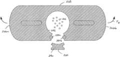
- FIG. 6is a cross-sectional view of the fiber optic cable showing a portion of the fiber optic cable separated from a remaining portion.
- FIG. 7is a side view of the fiber optic cable of FIG. 6 .
- FIG. 8is a cross-sectional view of an alternate embodiment of a fiber optic cable.
- FIG. 9is a cross-sectional view of the fiber optic cable of FIG. 8 with a portion of the fiber optic cable separated from a remaining portion.
- the fiber optic cable assembly 10includes at least one optical fiber 12 and a reinforcing member 14 .
- the fiber optic cable assembly 10further includes an outer jacket 16 that surrounds the optical fiber 12 and the strength member 14 .
- the fiber optic cable assembly 10includes a plurality of optical fibers 12 . In one embodiment, the fiber optic cable assembly 10 includes twelve optical fibers 12 . In another embodiment, the fiber optic cable assembly 10 includes 48, 72, or 144 optical fibers 12 .
- the optical fiber 12is shown.
- the optical fiber 12can have any number of configurations.
- the optical fiber 12includes a core 20 .
- the core 20is made of a glass material, such as a silica-based material, having an index of refraction.
- the core 20has an outer diameter D 1 of less than or equal to about 10 ⁇ m.
- the core 20 of each optical fiber 12is surrounded by a first cladding layer 22 that is also made of a glass material, such as a silica based-material.
- the first cladding layer 22has an index of refraction that is less than the index of refraction of the core 20 . This difference between the index of refraction of the first cladding layer 22 and the index of refraction of the core 20 allows an optical signal that is transmitted through the optical fiber 12 to be confined to the core 20 .
- a second cladding layer 24surrounds the first cladding layer 22 .
- the second cladding layer 24has an index of refraction.
- the index of refraction of the second cladding layer 24is about equal to the index of refraction of the first cladding layer 22 .
- the second cladding layer 24is immediately adjacent to the first cladding layer 22 .
- the second cladding layer 24has an outer diameter D 2 of less than or equal to 125 ⁇ m.
- a coating, generally designated 26surrounds the second cladding layer 24 .
- the coating 26includes an inner layer 28 and an outer layer 30 .
- the inner layer 28 of the coating 26is immediately adjacent to the second cladding layer 24 such that the inner layer 28 surrounds the second cladding layer 24 .
- the inner layer 28is a polymeric material (e.g., polyvinyl chloride, polyethylenes, polyurethanes, polypropylenes, polyvinylidene fluorides, ethylene vinyl acetate, nylon, polyester, or other materials) having a low modulus of elasticity.
- the low modulus of elasticity of the inner layer 28functions to protect the optical fiber 12 from microbending.
- the outer layer 30 of the coating 26is a polymeric material having a higher modulus of elasticity than the inner layer 28 .
- the outer layer 30 of the coating 26is immediately adjacent to the inner layer 28 such that the outer layer 30 surrounds the inner layer 28 .
- the higher modulus of elasticity of the outer layer 30functions to mechanically protect and retain the shape of optical fiber 12 during handling.
- the outer layer 30defines an outer diameter D 3 of less than or equal to 300 ⁇ m. In another embodiment, the outer diameter D 3 of the outer layer 30 is less than or equal to 250 ⁇ m. In another embodiment, the outer diameter D 3 of the outer layer 30 is less than or equal to 200 ⁇ m.
- the optical fiber 12is manufactured to reduce the sensitivity of the optical fiber 12 to micro or macro-bending (hereinafter referred to as “bend-insensitive”).
- An exemplary bend insensitive optical fiberhas been described in U.S. Pat. Nos. 7,587,111 and 7,623,747 that are hereby incorporated by reference in their entirety.
- An exemplary bend-insensitive optical fiberis commercially available from Draka Comteq under the name BendBright XS.
- a fiber bundle 32 of optical fibers 12is shown. While the optical fibers 12 can be loosely disposed in the fiber optic cable assembly 10 , the plurality of optical fibers 12 can be bundled to form the fiber bundle 32 . In the depicted embodiment of FIG. 4 , the optical fibers 12 are contra-helically served.
- the fiber bundle 32includes fiber grouping members 34 .
- the fiber grouping members 34are adapted to group the optical fibers 12 in the fiber bundle 32 .
- the fiber grouping members 34include a first fiber grouping member 34 a and a second fiber grouping member 34 b.
- the first and second fiber grouping members 34 a, 34 bare arranged immediately about the plurality of optical fibers 12 in a generally reverse double helical configuration along the length of the optical fibers 12 . With the first and second fiber grouping members 34 a, 34 b disposed immediately about the plurality of optical fibers 12 , there is no intermediate layer disposed between the first and second fiber grouping members 34 a, 34 b and the plurality of optical fibers 12 .
- the first fiber grouping member 34 aspirals about the length of the optical fibers 12 in a first direction while the second fiber grouping member 34 b spirals about the length of the optical fibers 12 in a second direction, which is opposite from the first direction.
- the first directionis a clockwise direction and the second direction is a counterclockwise direction.
- This reverse double helical arrangement of the first and second fiber grouping members 34 a, 34 b about the plurality of optical fibers 12groups and retains the plurality of optical fibers in the fiber bundle 32 .
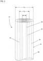
- the reinforcing member 14 of the fiber optic cable assembly 10is adapted to resist axial forces applied to the fiber optic cable assembly 10 .
- the reinforcing member 14preferably has a transverse cross-sectional profile that is generally rectangular in shape. As shown at FIG. 2 , the reinforcing member 14 has a transverse cross-sectional width W 1 that is greater than a transverse cross-sectional thickness T 1 of the reinforcing member 14 .
- the width W 1 of the reinforcing member 14is at least 50% longer than the thickness T 1 , or the width W 1 of the reinforcing member 14 is at least 75% longer than the thickness T 1 , or the width W 1 of the reinforcing member 14 is at least 100% longer than the thickness T 1 , or the width W 1 of the reinforcing member 14 is at least 200% longer than the thickness T 1 , or the width W 1 of the reinforcing member 14 is at least 300% longer than the thickness T 1 , or the width W 1 of the reinforcing member 14 is at least 400% longer than the thickness T 1 .
- the width W 1is a maximum width of the reinforcing member 14 and the thickness T 1 is a maximum thickness of the reinforcing member 14 .
- the reinforcing member 14preferably has a construction that is highly flexible and highly strong in tension.
- the reinforcing member 14provides the vast majority of the tensile load capacity of the fiber optic cable assembly 10 .
- the reinforcing member 14carries at least 95% of a 150 pound tensile load applied to the fiber optic cable assembly 10 in a direction along a lengthwise axis 35 .
- the reinforcing member 14can carry a 150 pound tensile load applied in an orientation extending along a central longitudinal axis of the reinforcing member 14 without undergoing meaningful deterioration of the tensile properties of the reinforcing member 14 .
- the reinforcing member 14can carry a 200 pound tensile load applied in an orientation extending along the central longitudinal axis of the reinforcing member 14 without undergoing meaningful deterioration in its tensile properties. In still another embodiment, the reinforcing member 14 can carry a 300 pound tensile load applied in an orientation that extends along the central longitudinal axis of the reinforcing member 14 without experiencing meaningful deterioration of its tensile properties.
- the reinforcing member 14is formed by a generally flat layer of reinforcing elements (e.g., fibers or yarns such as aramid fibers or yarns) embedded or otherwise integrated within a binder to form a flat reinforcing structure (e.g., a structure such as a sheet-like structure, a film-like structure, or a tape-like structure).
- the binderis a polymeric material such ethylene acetate acrylite (e.g., UV-cured, etc.), silicon (e.g., RTV, etc.), polyester films (e.g., biaxially oriented polyethylene terephthalate polyester film, etc.), and polyisobutylene.
- the bindermay be a matrix material, an adhesive material, a finish material, or another type of material that binds, couples or otherwise mechanically links together reinforcing elements.
- the reinforcing member 14can have a glass reinforced polymer (GRP) construction.
- the glass reinforced polymercan include a polymer base material reinforced by a plurality of glass fibers such as E-glass, S-glass or other types of glass fiber.
- the polymer used in the glass reinforced polymeris preferably relatively soft and flexible after curing.
- the polymerhas a Shore A hardness less than 50 after curing.
- the polymerhas a Shore A hardness less than 46 after curing.
- the polymerhas a Shore A hardness in the range of about 34-46.
- the reinforcing member 14can have a width of about 0.085 inches and a thickness of about 0.045 inches. In another embodiment, such a reinforcing member 14 may have a width of about 0.125 inches and a thickness of about 0.030 inches. In still further embodiments, the reinforcing member 14 has a thickness in the range of 0.020-0.040 inches, or in the range of 0.010-0.040 inches, or in the range of 0.025-0.035 inches. Of course, other dimensions could be used as well. In additional embodiments, the reinforcing member 14 may have a width in the range of 0.070-0.150 inches. Of course, other sizes could be used as well.
- the reinforcing member 14preferably does not provide the fiber optic cable assembly 10 with meaningful resistance to compression loading in an orientation extending along the lengthwise axis 35 .
- the outer jacket 16provides greater resistance to compression than the reinforcing member 14 in an orientation extending along the lengthwise axis 35 .
- the outer jacket 16 of the fiber optic cable assembly 10has a non-circular outer profile.
- the outer profile of the outer jacket 16has a flat generally obround or rectangular shape.
- the outer jacket 16includes a major axis 36 and a minor axis 38 .
- the major and minor axes 36 , 38are perpendicular to one another and intersect at a center 40 of the outer jacket 16 .
- a width W 2 of the outer jacket 16extends along the major axis 36 and a thickness T 2 of the outer jacket 16 extends along the minor axis 38 .
- the width W 2is longer than the thickness T 2 . In certain embodiments, the width W 2 is at least 50% longer than the thickness T 2 . As depicted in FIG. 1 , the width W 2 is a maximum width of the outer jacket 16 and the thickness T 2 is a maximum thickness of the outer jacket 16 .
- the outer jacket 16includes a base material that is a thermoplastic material.
- the base materialis a low-smoke zero halogen material such as low-smoke zero halogen polyolefin and polycarbonate.
- the base material of the outer jacket 16is a conventional thermoplastic material such as polyethylene, polypropylene, ethylene-propylene, copolymers, polystyrene and styrene copolymers, polyvinyl chloride, polyamide (nylon), polyesters such as polyethylene terephthalate, polyetheretherketone, polyphenylene sulfide, polyetherimide, polybutylene terephthalate, as well as other thermoplastic materials.
- the outer jacket 16includes a plurality of shrinkage reduction material disposed in the base material.
- the shrinkage reduction material in the base material of the outer jacket 16is adapted to resist post-extrusion shrinkage.
- U.S. Pat. No. 7,379,642describes an exemplary use of shrinkage reduction material in the base material of the outer jacket and is hereby incorporated by reference in its entirety.
- the shrinkage reduction materialis liquid crystal polymer (LCP).
- LCPliquid crystal polymer
- the concentration of shrinkage reduction materialis relatively small as compared to the base material.
- the shrinkage reduction materialconstitutes less than about 10% of the total weight of the outer jacket 16 .
- the shrinkage reduction materialconstitutes less than about 5% of the total weight of the outer jacket 16 .
- the shrinkage reduction materialconstitutes less than about 2% of the total weight of the outer jacket 16 .
- the shrinkage reduction materialconstitutes less than about 1.9%, less than about 1.8%, less than about 1.7%, less than about 1.6%, less than about 1.5%, less than about 1.4%, less than about 1.3%, less than about 1.2%, less than about 1.1%, or less than about 1% of the total weight of the outer jacket 16 .
- the outer jacket 16defines a first passage 42 and a second passage 44 .
- the first passage 42has a generally circular profile.
- the first passage 42defines a center that is offset from the center 40 of the outer jacket 16 .
- the first passage 42is adapted to receive the plurality of optical fibers 12 .
- the plurality of optical fibers 12is disposed directly in the first passage 42 so that there is no intermediate layer (e.g., buffer tube, strength layer, etc.) disposed between the plurality of optical fibers 12 and the outer jacket 16 .
- the first passage 42extends the length of the fiber optic cable assembly 10 .
- the second passage 44is adapted to receive the reinforcing member 14 .
- the second passage 44has a non-circular profile.
- the second passage 44when viewed in transverse cross-section, has a generally obround or rectangular shape.
- the reinforcing member 14is bonded to the second passage 44 of the outer jacket 16 .
- the bonding between the reinforcing member 14 and the outer jacket 16can be chemical bonding or thermal bonding.
- the reinforcing member 14may be coated with or otherwise provided with a material having bonding characteristics (e.g., ethylene acetate) to bond the reinforcing member 14 to the outer jacket 16 .
- the fiber optic cable assembly 10includes a wall 46 disposed between an outer surface 48 of the outer jacket 16 and an inner diameter of the first passage 42 .
- the outer jacket 16forms the wall 46 .
- the wall 46includes a thickness T 3 .
- the outer surface 48 of the wall 46is continuous. It will be understood that the term “continuous” means that there are no indentations or lines of weakness in the outer surface 48 of the outer jacket 16 .
- the fiber optic cable assembly 10further includes at least one access member 50 disposed in the wall 46 of the outer jacket 16 .
- the access member 50is a monofilament having a generally circular cross-section.
- the access member 50is made of a material having a melting point temperature that is greater than the melting point temperature of the material of the outer jacket 16 .
- the access member 50includes an outer diameter D.
- the outer diameter D of the access member 50is at least 30% of the thickness T 3 of the wall 46 .
- the outer diameter D of the access member 50is at least 40% of the thickness T 3 of the wall 46 .
- the outer jacket 16defines an access member passage 52 that extends the length of the fiber optic cable assembly 10 .
- the access member passage 52 of the outer jacket 16has an inner diameter that is generally equal to the outer diameter D of the access member 50 .
- the outer jacket 16includes a first portion 54 of the wall 46 and a second portion 56 .
- the first portion 54 of the wall 46extends between the outer surface 48 of the outer jacket 16 and the inner diameter of the access member passage 52 .
- the first portion 54 of the wall 46has a thickness T 4 .
- the second portion 56 of the wall 46extends between the inner diameter of the first passage 42 and the inner diameter of the access member passage 52 .
- the second portion 56 of the wall 46has a thickness T 5 .
- the second portion 56 of the wall 46is oppositely disposed from the first portion 54 of the wall 46 .
- the thickness T 4 of the first portion 54 , the thickness T 5 of the second portion 56 and the outer diameter D of the access member 50cooperatively make up the thickness T 3 of the wall 46 .
- the thickness T 4 of the first portion 54is generally equal to the thickness T 5 of the second portion 56 .
- the thickness T 4 of the first portion 54is at most 0.010 inches.
- the thickness T 4 of the first portion 54 of the wall 46is at most 0.0075 inches.
- the thickness T 4 of the first portion 54 of the wall 46is at most 0.005 inches.
- the thickness T 5 of the second portion 56is at most 0.010 inches.
- the thickness T 5 of the second portion 56 of the wall 46is at most 0.0075 inches.
- the thickness T 5 of the second portion 56 of the wall 46is at most 0.005 inches.
- the thickness T 4 of the first portion 54is generally equal to the thickness T 5 of the second portion 56 .
- the fiber optic cable assembly 10includes a first access member 50 a and a second access member 50 b.
- the first and second access members 50 a, 50 bare disposed on opposite sides of the first passage 42 so that each of the first and second access members 50 a, 50 b are disposed on an axis 58 that extends through a center of the first passage 42 where the axis 58 is generally perpendicular to the major axis 36 of the fiber optic cable assembly 10 .
- the first and second access members 50 a, 50 bare disposed on opposite sides of the fiber optic cable assembly 10 as divided by the major axis 36 but on the same side of the fiber optic cable assembly 10 as divided by the minor axis 38 .
- a force Fis applied to a portion 60 of the outer jacket 16 .
- the portion 60extends between the first and second access members 50 a, 50 b.
- the portion 60is on the opposite side of the minor axis 38 of the fiber optic cable assembly 10 from the reinforcing member 14 .
- the portion 60is less than or equal to half of the cross-sectional profile of the fiber optic cable assembly 10 .
- the portion 60is less than or equal to a third of the cross-sectional profile of the fiber optic cable assembly 10 .
- the force Fis applied to the portion 60 so that the force F extends outwardly from the lengthwise axis 35 of the fiber optic cable assembly 10 .
- the force Fis generally perpendicular to the lengthwise axis 35 .
- the force Fextends outwardly from the portion 60 in a first direction along the major axis 36 of the fiber optic cable assembly 10 .
- the force Fcan be applied with a tool such as pliers.
- the force Fis generally perpendicular to an access line 61 .
- the access line 61passes through the first and second portions 54 , 56 of the outer jacket 16 and the access member 50 .
- the access line 61passes through the center of the access member 50 .
- the portion 60is pulled in the first direction while a remaining portion 62 of the outer jacket 16 is held stationary. In another embodiment, the portion 60 is pulled in a first direction while the remaining portion 62 is pulled in a second direction that is opposite the first direction.
- the force F applied to the portion 60 of the fiber optic cable assembly 10is of a magnitude that causes the first and second portions 54 , 56 of the wall 46 to tear.
- the force Fis applied until a desired length L of the portion 60 has been broken away from the remaining portion 62 of the fiber optic cable assembly 10 .
- the access members 50 disposed in the wall 46provide a discontinuity in the wall 46 . Unlike a ripcord, a force is not applied to the access members 50 to create a break or tear in the wall.
- the force Fis only applied to the outer jacket 16 .
- the optical fibers 12 in the first passage 42are accessible so that the optical fibers 12 can be spliced or so that a fiber optic breakout can be installed.
- the portion 60 of the fiber optic cable assembly 10 that has been broken away from the fiber optic cable assembly 10is cut at opposite ends 64 a, 64 b of the portion 60 where the portion 60 is still engaged or connected to the fiber optic cable assembly 10 .
- the fiber optic cable assembly 210includes a plurality of optical fibers 212 , a first reinforcing member 214 a and a second reinforcing member 214 b and an outer jacket 216 .
- each of the first and second reinforcing members 214 a, 214 bhas a transverse cross-sectional profile that is generally rectangular in shape. As shown at FIG. 8 , the first and second reinforcing members 214 a, 214 b have a transverse cross-sectional width that is greater than a transverse cross-sectional thickness.
- the fiber optic cable assembly 210includes a central longitudinal axis.
- the outer jacket 216has a non-circular outer profile.
- the outer profile of the outer jacket 216has a flat generally obround or rectangular shape.
- the outer jacket 216includes a major axis 236 and a minor axis 238 .
- the major and minor axes 236 , 238are perpendicular to one another and intersect at a center 240 of the outer jacket 216 .
- a width of the outer jacket 216extends along the major axis 236 and a thickness of the outer jacket 216 extends along the minor axis 238 .
- the width of the outer jacket 216is longer than the thickness.
- the outer jacket 216 of the fiber optic cable assembly 210defines a fiber passage 242 that extends along the central longitudinal axis.
- the fiber passage 242is disposed at the center 240 of the fiber optic cable assembly 210 .
- the outer jacket 216further defines second and third passages 244 a, 244 b.
- the second passage 244 ais adapted to receive the first reinforcing member 214 a while the third passage 244 b is adapted to receive the second reinforcing member 214 b.
- the second and third passages 244 a, 244 bare generally aligned with the major axis 236 .
- the second and third passages 244 a, 244 bare disposed on opposite sides of the minor axis 238 .
- the fiber optic cable assembly 210includes a wall 246 disposed between an outer surface 248 of the outer jacket 216 and an inner diameter of the fiber passage 242 .
- the outer jacket 216forms the wall 246 .
- the fiber optic cable assembly 210further includes a first access member 250 a and a second access member 250 b.
- the first and second access members 250 a, 250 bare embedded in the outer jacket 216 .
- the first and second access members 250 a, 250 bare disposed in first and second access member passages 252 a, 252 b defined by the wall 246 .
- the first and second access member passages 252 a, 252 bare disposed on the same side of the fiber optic cable assembly 210 as divided by the major axis 236 but on opposite sides of the fiber optic cable assembly 210 as divided by the minor axis 238 .
- a bending force F Bis applied to the outer jacket 216 of the fiber optic cable assembly 210 .
- the bending force F Bis applied to the fiber optic cable assembly 210 so that a first portion 260 of the outer jacket 216 is under tension while a second portion 262 is under compression.
- the first portion 260extends between the first and second access members 250 a, 250 b.
- the first portion 260is disposed between the first and second reinforcing members 214 a, 214 b.
- the bending force F Bis applied to first and second sides 266 a, 266 b of the fiber optic cable assembly 210 so that the first portion 260 is under tension while the second portion 262 is under compression.
- the bending force F B applied to the fiber optic cable assembly 210causes the wall 246 to tear.
- the bending force F Bis applied until a desired length of the first portion 260 has been broken away from the fiber optic cable assembly 210 .
- the optical fibers 212 in the fiber passage 242are accessible so that the optical fibers 212 can be spliced or so that a fiber optic breakout can be installed.
Landscapes
- Physics & Mathematics (AREA)
- General Physics & Mathematics (AREA)
- Optics & Photonics (AREA)
- Light Guides In General And Applications Therefor (AREA)
- Communication Cables (AREA)
Abstract
Description
Claims (32)
Priority Applications (1)
| Application Number | Priority Date | Filing Date | Title |
|---|---|---|---|
| US18/101,817USRE50314E1 (en) | 2010-03-02 | 2023-01-26 | Fiber optic cable assembly and method |
Applications Claiming Priority (4)
| Application Number | Priority Date | Filing Date | Title |
|---|---|---|---|
| US30967610P | 2010-03-02 | 2010-03-02 | |
| US39421810P | 2010-10-18 | 2010-10-18 | |
| US13/038,996US8363994B2 (en) | 2010-03-02 | 2011-03-02 | Fiber optic cable assembly |
| US18/101,817USRE50314E1 (en) | 2010-03-02 | 2023-01-26 | Fiber optic cable assembly and method |
Related Parent Applications (1)
| Application Number | Title | Priority Date | Filing Date |
|---|---|---|---|
| US13/038,996ReissueUS8363994B2 (en) | 2010-03-02 | 2011-03-02 | Fiber optic cable assembly |
Publications (1)
| Publication Number | Publication Date |
|---|---|
| USRE50314E1true USRE50314E1 (en) | 2025-02-25 |
Family
ID=44531406
Family Applications (2)
| Application Number | Title | Priority Date | Filing Date |
|---|---|---|---|
| US13/038,996CeasedUS8363994B2 (en) | 2010-03-02 | 2011-03-02 | Fiber optic cable assembly |
| US18/101,817ActiveUSRE50314E1 (en) | 2010-03-02 | 2023-01-26 | Fiber optic cable assembly and method |
Family Applications Before (1)
| Application Number | Title | Priority Date | Filing Date |
|---|---|---|---|
| US13/038,996CeasedUS8363994B2 (en) | 2010-03-02 | 2011-03-02 | Fiber optic cable assembly |
Country Status (3)
| Country | Link |
|---|---|
| US (2) | US8363994B2 (en) |
| EP (2) | EP3929644A1 (en) |
| WO (1) | WO2011109498A2 (en) |
Families Citing this family (26)
| Publication number | Priority date | Publication date | Assignee | Title |
|---|---|---|---|---|
| WO2009155037A2 (en)* | 2008-05-28 | 2009-12-23 | Adc Telecommunications, Inc. | Fiber optic cable |
| AU2009342250B2 (en)* | 2009-03-16 | 2015-02-26 | Prysmian S.P.A. | Optical cable with improved strippability |
| EP3929644A1 (en) | 2010-03-02 | 2021-12-29 | Commscope Technologies LLC | Fiber optic cable assembly |
| US8885999B2 (en)* | 2010-03-19 | 2014-11-11 | Corning Cable Systems Llc | Optical USB cable with controlled fiber positioning |
| JP6017415B2 (en) | 2010-04-30 | 2016-11-02 | コーニング オプティカル コミュニケイションズ リミテッド ライアビリティ カンパニー | Optical fiber cable with access feature and method of manufacturing the same |
| CN103221862B (en) | 2010-10-28 | 2016-10-26 | 康宁光缆系统有限责任公司 | Fiber optic cable with extruded access features and method for making fiber optic cable |
| WO2012071490A2 (en) | 2010-11-23 | 2012-05-31 | Corning Cable Systems Llc | Fiber optic cables with access features |
| US9323022B2 (en) | 2012-10-08 | 2016-04-26 | Corning Cable Systems Llc | Methods of making and accessing cables having access features |
| US8682124B2 (en) | 2011-10-13 | 2014-03-25 | Corning Cable Systems Llc | Access features of armored flat fiber optic cable |
| AU2012322864A1 (en)* | 2011-10-13 | 2014-04-17 | Corning Optical Communications LLC | Methods of making and accessing cables having access features |
| US9274302B2 (en) | 2011-10-13 | 2016-03-01 | Corning Cable Systems Llc | Fiber optic cables with extruded access features for access to a cable cavity |
| US9201208B2 (en) | 2011-10-27 | 2015-12-01 | Corning Cable Systems Llc | Cable having core, jacket and polymeric jacket access features located in the jacket |
| US9176293B2 (en) | 2011-10-28 | 2015-11-03 | Corning Cable Systems Llc | Buffered fibers with access features |
| US8909014B2 (en) | 2012-04-27 | 2014-12-09 | Corning Cable Systems Llc | Fiber optic cable with access features and jacket-to-core coupling, and methods of making the same |
| US9557505B2 (en) | 2013-03-18 | 2017-01-31 | Commscope Technologies Llc | Power and optical fiber interface |
| CN105247805B (en) | 2013-03-18 | 2017-12-08 | 阿德斯电信公司 | Framework for wireless network |
| CN105247627B (en) | 2013-05-14 | 2018-08-10 | 阿德斯电信公司 | Power/Fiber Optic Hybrid Cable |
| US9482839B2 (en) | 2013-08-09 | 2016-11-01 | Corning Cable Systems Llc | Optical fiber cable with anti-split feature |
| CA2937453C (en) | 2014-01-22 | 2021-05-04 | Adc Telecommunications, Inc. | Flat drop cable with features for enhancing stripability |
| KR102504156B1 (en)* | 2014-12-19 | 2023-02-28 | 다우 글로벌 테크놀로지스 엘엘씨 | Cable jackets having designed microstructures and methods for making cable jackets having designed microstructures |
| US9823431B2 (en) | 2015-06-04 | 2017-11-21 | Google Llc | Rapid deploy outdoor cable |
| WO2017158470A1 (en)* | 2016-03-14 | 2017-09-21 | 3M Innovative Properties Company | Cable assembly with a removable installation device |
| US10310209B2 (en)* | 2016-03-31 | 2019-06-04 | Ofs Fitel, Llc | Tight-buffered optical fiber having improved fiber access |
| WO2018089623A1 (en) | 2016-11-09 | 2018-05-17 | Commscope, Inc. Of North Carolina | Exchangeable powered infrastructure module |
| AU2018250693B2 (en) | 2017-04-13 | 2022-03-10 | Commscope Technologies Llc | Flat drop cable with features for enhanced stripability |
| KR102595175B1 (en) | 2018-03-14 | 2023-10-30 | 삼성전자주식회사 | Lithium secondary battery comprising the electrolyte containing trialkoxyalkylsilane compound |
Citations (80)
| Publication number | Priority date | Publication date | Assignee | Title |
|---|---|---|---|---|
| US3991014A (en) | 1974-05-10 | 1976-11-09 | E. I. Du Pont De Nemours And Company | Polyesters of derivatives of hydroquinone and bis(carboxyphenyl)ether |
| US4067852A (en) | 1976-05-13 | 1978-01-10 | Celanese Corporation | Melt processable thermotropic wholly aromatic polyester containing polybenzoyl units |
| US4083829A (en) | 1976-05-13 | 1978-04-11 | Celanese Corporation | Melt processable thermotropic wholly aromatic polyester |
| US4130545A (en) | 1977-09-12 | 1978-12-19 | Celanese Corporation | Melt processable thermotropic wholly aromatic polyester comprising both para-oxybenzoyl and meta-oxybenzoyl moieties |
| US4161470A (en) | 1977-10-20 | 1979-07-17 | Celanese Corporation | Polyester of 6-hydroxy-2-naphthoic acid and para-hydroxy benzoic acid capable of readily undergoing melt processing |
| US4318842A (en) | 1980-10-06 | 1982-03-09 | Celanese Corporation | Polyester of 6-hydroxy-2-naphthoic acid, aromatic diol, and 1,4-cyclohexanedicarboxylic acid capable of undergoing melt processing |
| US4456331A (en) | 1979-05-22 | 1984-06-26 | The Post Office | Improved communications cable with lines of weakness |
| US4468364A (en) | 1983-04-28 | 1984-08-28 | Celanese Corporation | Process for extruding thermotropic liquid crystalline polymers |
| JPS6091306A (en) | 1983-10-25 | 1985-05-22 | Hitachi Cable Ltd | Reinforcing method of connection part terminal of multicore optical fiber |
| US4729628A (en) | 1986-11-14 | 1988-03-08 | Siecor Corporation | Fiber optic dropwire |
| EP0259051A2 (en) | 1986-09-02 | 1988-03-09 | Cooper Industries, Inc. | Under carpet flat cable assembly and method of forming a turn in same |
| US5442722A (en) | 1994-07-25 | 1995-08-15 | Siecor Corporation | Optical fiber ribbon with zip cord |
| US5651081A (en)* | 1994-06-10 | 1997-07-22 | Commscope, Inc. | Composite fiber optic and electrical cable and associated fabrication method |
| US5717805A (en) | 1996-06-12 | 1998-02-10 | Alcatel Na Cable Systems, Inc. | Stress concentrations in an optical fiber ribbon to facilitate separation of ribbon matrix material |
| US5970196A (en) | 1997-09-22 | 1999-10-19 | Siecor Corporation | Fiber optic protective member with removable section to facilitate separation thereof |
| US6088499A (en) | 1997-09-30 | 2000-07-11 | Siecor Corporation | Fiber optic cable with ripcord |
| US6137936A (en)* | 1999-07-22 | 2000-10-24 | Pirelli Cables And Systems Llc | Optical fiber cable with single strength member in cable outer jacket |
| US6167180A (en)* | 1997-09-12 | 2000-12-26 | Alcatel | Cable having at least one layer of flexible strength members with adhesive and non-adhesive yarns for coupling an outer protective jacket and a buffer tube containing optical fibers |
| US6493491B1 (en)* | 1999-09-28 | 2002-12-10 | Alcatel | Optical drop cable for aerial installation |
| US6542674B1 (en) | 2000-08-25 | 2003-04-01 | Corning Cable Systems Llc | Fiber optic cables with strength members |
| WO2003060579A2 (en) | 2002-01-18 | 2003-07-24 | Ccs Technology, Inc. | Fibre optic cable for installing in a gas conduit and a cable laying device |
| US6813421B2 (en) | 2001-12-26 | 2004-11-02 | Corning Cable Systems Llc | Fiber optic cable having a ripcord |
| US20050213903A1 (en)* | 2004-03-25 | 2005-09-29 | Mohler James D | Fiber optic drop cables suitable for outdoor fiber to the subscriber applications |
| US20050213899A1 (en)* | 2004-03-25 | 2005-09-29 | Hurley William C | Fiber optic drop cables suitable for outdoor fiber to the subscriber applications |
| EP1031862B1 (en) | 1999-02-18 | 2005-11-16 | Draka Comteq B.V. | Method for accessing optical fibers in the midspan region of an optical fiber cable |
| US20060127016A1 (en)* | 2004-12-15 | 2006-06-15 | Baird Paul R | Fiber optic cables with easy access features |
| KR20060081266A (en) | 2005-01-07 | 2006-07-12 | 엘에스전선 주식회사 | Pneumatic installation optical fiber cable with tension cord with lip cord function |
| WO2006097540A1 (en) | 2005-03-18 | 2006-09-21 | Siemens Aktiengesellschaft | Strip device |
| KR20060107414A (en) | 2005-04-08 | 2006-10-13 | 넥쌍 | Low flammable fiber |
| US20060269198A1 (en)* | 2005-05-31 | 2006-11-30 | Blazer Bradley J | Fiber optic cables that are separable for optical fiber access |
| US20060291787A1 (en)* | 2005-06-27 | 2006-12-28 | Seddon David A | Fiber optic cable having strength component |
| US20070047884A1 (en)* | 2005-08-25 | 2007-03-01 | Draka Comteq B.V. | Fiber optic cable with a concave surface |
| US7218821B2 (en)* | 2004-08-20 | 2007-05-15 | Furukawa Electric North America Inc. | Optical fiber cables |
| US20070182054A1 (en) | 2006-01-12 | 2007-08-09 | Kachmar Wayne M | Method for manufacturing product markers |
| US20080013899A1 (en)* | 2001-03-23 | 2008-01-17 | Gowan Russell W | Coated central strength member for fiber optic cables with reduced shrinkage |
| US7379642B2 (en) | 2005-01-18 | 2008-05-27 | Adc Telecommunications, Inc. | Low shrink telecommunications cable and methods for manufacturing the same |
| US7466890B2 (en) | 2006-09-13 | 2008-12-16 | Adc Telecommunications, Inc. | Cabinet access sensor |
| US20090034917A1 (en)* | 2007-08-02 | 2009-02-05 | Shawcor Ltd. | System for splicing fiber drop cables |
| US7490994B2 (en) | 2006-11-29 | 2009-02-17 | Adc Telecommunications, Inc. | Hybrid fiber/copper connector system and method |
| US20090087148A1 (en)* | 2007-09-28 | 2009-04-02 | Bradley Kelvin B | Optical fiber cables |
| US7530746B2 (en) | 2007-04-13 | 2009-05-12 | Abc Telecommunications, Inc. | Field termination connector with shaped adhesive pre-form |
| US7534050B2 (en) | 2007-04-13 | 2009-05-19 | Adc Telecommunications, Inc. | Field terminatable fiber optic connector assembly |
| JP2009186714A (en)* | 2008-02-06 | 2009-08-20 | Sumitomo Electric Ind Ltd | Fiber optic cable |
| US7587111B2 (en) | 2006-04-10 | 2009-09-08 | Draka Comteq B.V. | Single-mode optical fiber |
| US7590321B2 (en)* | 2006-03-09 | 2009-09-15 | Adc Telecommunications, Inc. | Mid-span breakout with helical fiber routing |
| US20090274425A1 (en) | 2007-07-31 | 2009-11-05 | Corning Cable Systems Llc, | Fiber Optic Cables Having Coupling and Methods Therefor |
| US7623747B2 (en) | 2005-11-10 | 2009-11-24 | Draka Comteq B.V. | Single mode optical fiber |
| US20090297102A1 (en) | 2008-05-28 | 2009-12-03 | Adc Telecommunications, Inc. | Fiber optic cable for connectorization and method |
| US20090297104A1 (en) | 2008-05-28 | 2009-12-03 | Kachmar Wayne M | Fiber optic cable |
| US20090294016A1 (en) | 2008-05-27 | 2009-12-03 | Derek Sayres | Flexible extruded cable molding system, methods, and tools |
| US7630066B2 (en) | 2007-03-30 | 2009-12-08 | Adc Telecommunications, Inc. | Optical fiber inspection tool |
| US20090317038A1 (en) | 2008-03-28 | 2009-12-24 | Kachmar Wayne M | Multi-fiber fiber optic cable |
| US7676134B2 (en) | 2007-04-13 | 2010-03-09 | Adc Telecommunications, Inc. | Field termination kit |
| US7693375B2 (en)* | 2002-12-19 | 2010-04-06 | Corning Cable Systems Llc | Fiber optic cable having a dry insert |
| US20100119197A1 (en) | 2008-07-10 | 2010-05-13 | Jarrod Scadden | Field Terminable Fiber Optic Connector Assembly |
| US20100220964A1 (en)* | 2008-09-30 | 2010-09-02 | De Jong Michael | Fiber Optic Drop Cable Furcation Assemblies and Methods |
| US7811156B2 (en) | 2007-03-30 | 2010-10-12 | Adc Telecommunications, Inc. | Optical fiber preparation device |
| US7817891B2 (en)* | 2007-04-11 | 2010-10-19 | Draka Comteq, B.V. | Method for accessing optical fibers within a telecommunication cable |
| US7869678B2 (en) | 2005-02-11 | 2011-01-11 | Adc Telecommunications, Inc. | Telecommunications cable jacket adapted for post-extrusion insertion of optical fiber and methods for manufacturing the same |
| US7873249B2 (en) | 2008-05-27 | 2011-01-18 | Adc Telecommunications, Inc. | Foamed fiber optic cable |
| US20110019963A1 (en) | 2009-05-29 | 2011-01-27 | Kenneth Allen Skluzacek | Field Terminable Fiber Optic Connector Assembly |
| US20110091170A1 (en) | 2009-10-21 | 2011-04-21 | Adc Telecommunications, Inc. | Fiber distribution hub and cable for use therewith |
| US20110150398A1 (en) | 2009-11-20 | 2011-06-23 | Adc Telecommunications, Inc. | Fiber Optic Cable Assembly |
| US20110217010A1 (en) | 2010-03-02 | 2011-09-08 | Adc Telecommunications, Inc. | Fiber optic cable assembly |
| US20110222825A1 (en) | 2010-03-11 | 2011-09-15 | Adc Telecommunications, Inc. | Optical fiber assembly |
| US8041166B2 (en) | 2008-10-28 | 2011-10-18 | Adc Telecommunications, Inc. | Flat drop cable |
| US20110280521A1 (en) | 2010-05-12 | 2011-11-17 | Adc Telecommunications, Inc. | Fiber optic connector and method of applying same to a fiber optic cable |
| US20110286707A1 (en) | 2010-05-19 | 2011-11-24 | Adc Telecommunications, Inc. | Flat drop cable with medial bump |
| US20110311185A1 (en) | 2010-05-19 | 2011-12-22 | Adc Telecommunications, Inc. | In-line splice with integrated splice holder |
| US8083416B2 (en) | 2007-11-30 | 2011-12-27 | Adc Telecommunications, Inc. | Hybrid fiber/copper connector system and method |
| US8107781B2 (en) | 2009-11-20 | 2012-01-31 | Adc Telecommunications, Inc. | Fiber optic cable |
| US8184935B2 (en) | 2009-10-21 | 2012-05-22 | Adc Telecommunications, Inc. | Flat drop cable with center strength member |
| US20120128309A1 (en) | 2010-05-19 | 2012-05-24 | Adc Telecommunications, Inc. | Lashing Together Multiple Fiber Optic Telecommunications Cables |
| US8224141B2 (en) | 2008-05-27 | 2012-07-17 | Adc Telecommunications, Inc. | Multi-jacketed fiber optic cable |
| US8995809B2 (en) | 2010-11-23 | 2015-03-31 | Corning Optical Communications LLC | Fiber optic cables with access features |
| US9073243B2 (en) | 2010-04-30 | 2015-07-07 | Corning Cable Systems Llc | Fiber optic cables with access features and methods of making fiber optic cables |
| US9664872B2 (en) | 2011-10-13 | 2017-05-30 | Corning Optical Communications LLC | Fiber optic cables with extruded access features for access to a cable cavity |
| US10228529B2 (en) | 2011-10-27 | 2019-03-12 | Corning Optical Communications LLC | Cable having core, jacket and polymeric jacket access features located in the jacket |
| US10613288B2 (en) | 2010-10-28 | 2020-04-07 | Corning Optical Communications LLC | Fiber optic cables with extruded access features and methods of making fiber optic cables |
| US20230401089A1 (en)* | 2022-06-14 | 2023-12-14 | Dell Products L.P. | Credit-based scheduling using load prediction |
Family Cites Families (6)
| Publication number | Priority date | Publication date | Assignee | Title |
|---|---|---|---|---|
| US14A (en) | 1836-08-31 | petess | ||
| US3991A (en) | 1845-04-10 | photo-litho | ||
| EP1362603B1 (en)* | 2002-05-14 | 2006-03-01 | Terumo Kabushiki Kaisha | Coated stent for release of active agents |
| US7208190B2 (en)* | 2002-11-07 | 2007-04-24 | Abbott Laboratories | Method of loading beneficial agent to a prosthesis by fluid-jet application |
| US20050216075A1 (en)* | 2003-04-08 | 2005-09-29 | Xingwu Wang | Materials and devices of enhanced electromagnetic transparency |
| DE102004062394B4 (en)* | 2004-12-23 | 2008-05-29 | Siemens Ag | Intravenous pacemaker electrode and process for its preparation |
- 2011
- 2011-03-02EPEP21191329.8Apatent/EP3929644A1/enactivePending
- 2011-03-02USUS13/038,996patent/US8363994B2/ennot_activeCeased
- 2011-03-02EPEP11751273.1Apatent/EP2542933B1/enactiveActive
- 2011-03-02WOPCT/US2011/026846patent/WO2011109498A2/enactiveApplication Filing
- 2023
- 2023-01-26USUS18/101,817patent/USRE50314E1/enactiveActive
Patent Citations (86)
| Publication number | Priority date | Publication date | Assignee | Title |
|---|---|---|---|---|
| US3991014A (en) | 1974-05-10 | 1976-11-09 | E. I. Du Pont De Nemours And Company | Polyesters of derivatives of hydroquinone and bis(carboxyphenyl)ether |
| US4067852A (en) | 1976-05-13 | 1978-01-10 | Celanese Corporation | Melt processable thermotropic wholly aromatic polyester containing polybenzoyl units |
| US4083829A (en) | 1976-05-13 | 1978-04-11 | Celanese Corporation | Melt processable thermotropic wholly aromatic polyester |
| US4130545A (en) | 1977-09-12 | 1978-12-19 | Celanese Corporation | Melt processable thermotropic wholly aromatic polyester comprising both para-oxybenzoyl and meta-oxybenzoyl moieties |
| US4161470A (en) | 1977-10-20 | 1979-07-17 | Celanese Corporation | Polyester of 6-hydroxy-2-naphthoic acid and para-hydroxy benzoic acid capable of readily undergoing melt processing |
| US4456331A (en) | 1979-05-22 | 1984-06-26 | The Post Office | Improved communications cable with lines of weakness |
| US4318842A (en) | 1980-10-06 | 1982-03-09 | Celanese Corporation | Polyester of 6-hydroxy-2-naphthoic acid, aromatic diol, and 1,4-cyclohexanedicarboxylic acid capable of undergoing melt processing |
| US4468364A (en) | 1983-04-28 | 1984-08-28 | Celanese Corporation | Process for extruding thermotropic liquid crystalline polymers |
| JPS6091306A (en) | 1983-10-25 | 1985-05-22 | Hitachi Cable Ltd | Reinforcing method of connection part terminal of multicore optical fiber |
| EP0259051A2 (en) | 1986-09-02 | 1988-03-09 | Cooper Industries, Inc. | Under carpet flat cable assembly and method of forming a turn in same |
| US4729628A (en) | 1986-11-14 | 1988-03-08 | Siecor Corporation | Fiber optic dropwire |
| US5651081A (en)* | 1994-06-10 | 1997-07-22 | Commscope, Inc. | Composite fiber optic and electrical cable and associated fabrication method |
| US5442722A (en) | 1994-07-25 | 1995-08-15 | Siecor Corporation | Optical fiber ribbon with zip cord |
| US5717805A (en) | 1996-06-12 | 1998-02-10 | Alcatel Na Cable Systems, Inc. | Stress concentrations in an optical fiber ribbon to facilitate separation of ribbon matrix material |
| US6167180A (en)* | 1997-09-12 | 2000-12-26 | Alcatel | Cable having at least one layer of flexible strength members with adhesive and non-adhesive yarns for coupling an outer protective jacket and a buffer tube containing optical fibers |
| US5970196A (en) | 1997-09-22 | 1999-10-19 | Siecor Corporation | Fiber optic protective member with removable section to facilitate separation thereof |
| US6088499A (en) | 1997-09-30 | 2000-07-11 | Siecor Corporation | Fiber optic cable with ripcord |
| EP1031862B1 (en) | 1999-02-18 | 2005-11-16 | Draka Comteq B.V. | Method for accessing optical fibers in the midspan region of an optical fiber cable |
| US6137936A (en)* | 1999-07-22 | 2000-10-24 | Pirelli Cables And Systems Llc | Optical fiber cable with single strength member in cable outer jacket |
| US6493491B1 (en)* | 1999-09-28 | 2002-12-10 | Alcatel | Optical drop cable for aerial installation |
| US6542674B1 (en) | 2000-08-25 | 2003-04-01 | Corning Cable Systems Llc | Fiber optic cables with strength members |
| US20080013899A1 (en)* | 2001-03-23 | 2008-01-17 | Gowan Russell W | Coated central strength member for fiber optic cables with reduced shrinkage |
| US7346244B2 (en)* | 2001-03-23 | 2008-03-18 | Draka Comteq B.V. | Coated central strength member for fiber optic cables with reduced shrinkage |
| US6813421B2 (en) | 2001-12-26 | 2004-11-02 | Corning Cable Systems Llc | Fiber optic cable having a ripcord |
| WO2003060579A2 (en) | 2002-01-18 | 2003-07-24 | Ccs Technology, Inc. | Fibre optic cable for installing in a gas conduit and a cable laying device |
| US7693375B2 (en)* | 2002-12-19 | 2010-04-06 | Corning Cable Systems Llc | Fiber optic cable having a dry insert |
| US20050213903A1 (en)* | 2004-03-25 | 2005-09-29 | Mohler James D | Fiber optic drop cables suitable for outdoor fiber to the subscriber applications |
| US20050213899A1 (en)* | 2004-03-25 | 2005-09-29 | Hurley William C | Fiber optic drop cables suitable for outdoor fiber to the subscriber applications |
| US7218821B2 (en)* | 2004-08-20 | 2007-05-15 | Furukawa Electric North America Inc. | Optical fiber cables |
| US7197215B2 (en)* | 2004-12-15 | 2007-03-27 | Corning Cable Systems, Llc. | Fiber optic cables with easy access features |
| US20060127016A1 (en)* | 2004-12-15 | 2006-06-15 | Baird Paul R | Fiber optic cables with easy access features |
| KR20060081266A (en) | 2005-01-07 | 2006-07-12 | 엘에스전선 주식회사 | Pneumatic installation optical fiber cable with tension cord with lip cord function |
| US7379642B2 (en) | 2005-01-18 | 2008-05-27 | Adc Telecommunications, Inc. | Low shrink telecommunications cable and methods for manufacturing the same |
| US8090232B2 (en) | 2005-01-18 | 2012-01-03 | Adc Telecommunications, Inc. | Low shrink telecommunications cable and methods for manufacturing the same |
| US7869678B2 (en) | 2005-02-11 | 2011-01-11 | Adc Telecommunications, Inc. | Telecommunications cable jacket adapted for post-extrusion insertion of optical fiber and methods for manufacturing the same |
| WO2006097540A1 (en) | 2005-03-18 | 2006-09-21 | Siemens Aktiengesellschaft | Strip device |
| KR20060107414A (en) | 2005-04-08 | 2006-10-13 | 넥쌍 | Low flammable fiber |
| US20060269198A1 (en)* | 2005-05-31 | 2006-11-30 | Blazer Bradley J | Fiber optic cables that are separable for optical fiber access |
| US7391943B2 (en) | 2005-05-31 | 2008-06-24 | Corning Cable Systems Llc | Fiber optic cables that are separable for optical fiber access |
| US20060291787A1 (en)* | 2005-06-27 | 2006-12-28 | Seddon David A | Fiber optic cable having strength component |
| US7391944B2 (en)* | 2005-08-25 | 2008-06-24 | Draka Comteq B.V. | Fiber optic cable with a concave surface |
| US20070047884A1 (en)* | 2005-08-25 | 2007-03-01 | Draka Comteq B.V. | Fiber optic cable with a concave surface |
| US7623747B2 (en) | 2005-11-10 | 2009-11-24 | Draka Comteq B.V. | Single mode optical fiber |
| US20070182054A1 (en) | 2006-01-12 | 2007-08-09 | Kachmar Wayne M | Method for manufacturing product markers |
| US7590321B2 (en)* | 2006-03-09 | 2009-09-15 | Adc Telecommunications, Inc. | Mid-span breakout with helical fiber routing |
| US7587111B2 (en) | 2006-04-10 | 2009-09-08 | Draka Comteq B.V. | Single-mode optical fiber |
| US7466890B2 (en) | 2006-09-13 | 2008-12-16 | Adc Telecommunications, Inc. | Cabinet access sensor |
| US7490994B2 (en) | 2006-11-29 | 2009-02-17 | Adc Telecommunications, Inc. | Hybrid fiber/copper connector system and method |
| US7811156B2 (en) | 2007-03-30 | 2010-10-12 | Adc Telecommunications, Inc. | Optical fiber preparation device |
| US7630066B2 (en) | 2007-03-30 | 2009-12-08 | Adc Telecommunications, Inc. | Optical fiber inspection tool |
| US7817891B2 (en)* | 2007-04-11 | 2010-10-19 | Draka Comteq, B.V. | Method for accessing optical fibers within a telecommunication cable |
| US7534050B2 (en) | 2007-04-13 | 2009-05-19 | Adc Telecommunications, Inc. | Field terminatable fiber optic connector assembly |
| US7530746B2 (en) | 2007-04-13 | 2009-05-12 | Abc Telecommunications, Inc. | Field termination connector with shaped adhesive pre-form |
| US7676134B2 (en) | 2007-04-13 | 2010-03-09 | Adc Telecommunications, Inc. | Field termination kit |
| US20090274425A1 (en) | 2007-07-31 | 2009-11-05 | Corning Cable Systems Llc, | Fiber Optic Cables Having Coupling and Methods Therefor |
| US20090034917A1 (en)* | 2007-08-02 | 2009-02-05 | Shawcor Ltd. | System for splicing fiber drop cables |
| US20090087148A1 (en)* | 2007-09-28 | 2009-04-02 | Bradley Kelvin B | Optical fiber cables |
| US8083416B2 (en) | 2007-11-30 | 2011-12-27 | Adc Telecommunications, Inc. | Hybrid fiber/copper connector system and method |
| JP2009186714A (en)* | 2008-02-06 | 2009-08-20 | Sumitomo Electric Ind Ltd | Fiber optic cable |
| US20090317038A1 (en) | 2008-03-28 | 2009-12-24 | Kachmar Wayne M | Multi-fiber fiber optic cable |
| US8224141B2 (en) | 2008-05-27 | 2012-07-17 | Adc Telecommunications, Inc. | Multi-jacketed fiber optic cable |
| US20090294016A1 (en) | 2008-05-27 | 2009-12-03 | Derek Sayres | Flexible extruded cable molding system, methods, and tools |
| US7873249B2 (en) | 2008-05-27 | 2011-01-18 | Adc Telecommunications, Inc. | Foamed fiber optic cable |
| US20090297104A1 (en) | 2008-05-28 | 2009-12-03 | Kachmar Wayne M | Fiber optic cable |
| US20090297102A1 (en) | 2008-05-28 | 2009-12-03 | Adc Telecommunications, Inc. | Fiber optic cable for connectorization and method |
| US20100119197A1 (en) | 2008-07-10 | 2010-05-13 | Jarrod Scadden | Field Terminable Fiber Optic Connector Assembly |
| US20100220964A1 (en)* | 2008-09-30 | 2010-09-02 | De Jong Michael | Fiber Optic Drop Cable Furcation Assemblies and Methods |
| US8041166B2 (en) | 2008-10-28 | 2011-10-18 | Adc Telecommunications, Inc. | Flat drop cable |
| US20110019963A1 (en) | 2009-05-29 | 2011-01-27 | Kenneth Allen Skluzacek | Field Terminable Fiber Optic Connector Assembly |
| US8184935B2 (en) | 2009-10-21 | 2012-05-22 | Adc Telecommunications, Inc. | Flat drop cable with center strength member |
| US20110091170A1 (en) | 2009-10-21 | 2011-04-21 | Adc Telecommunications, Inc. | Fiber distribution hub and cable for use therewith |
| US20110150398A1 (en) | 2009-11-20 | 2011-06-23 | Adc Telecommunications, Inc. | Fiber Optic Cable Assembly |
| US8107781B2 (en) | 2009-11-20 | 2012-01-31 | Adc Telecommunications, Inc. | Fiber optic cable |
| US20110217010A1 (en) | 2010-03-02 | 2011-09-08 | Adc Telecommunications, Inc. | Fiber optic cable assembly |
| US20110222825A1 (en) | 2010-03-11 | 2011-09-15 | Adc Telecommunications, Inc. | Optical fiber assembly |
| US9073243B2 (en) | 2010-04-30 | 2015-07-07 | Corning Cable Systems Llc | Fiber optic cables with access features and methods of making fiber optic cables |
| US9658422B2 (en) | 2010-04-30 | 2017-05-23 | Corning Optical Communications LLC | Fiber optic cables with access features and methods of making fiber optic cables |
| US20110280521A1 (en) | 2010-05-12 | 2011-11-17 | Adc Telecommunications, Inc. | Fiber optic connector and method of applying same to a fiber optic cable |
| US20120128309A1 (en) | 2010-05-19 | 2012-05-24 | Adc Telecommunications, Inc. | Lashing Together Multiple Fiber Optic Telecommunications Cables |
| US20110311185A1 (en) | 2010-05-19 | 2011-12-22 | Adc Telecommunications, Inc. | In-line splice with integrated splice holder |
| US20110286707A1 (en) | 2010-05-19 | 2011-11-24 | Adc Telecommunications, Inc. | Flat drop cable with medial bump |
| US10613288B2 (en) | 2010-10-28 | 2020-04-07 | Corning Optical Communications LLC | Fiber optic cables with extruded access features and methods of making fiber optic cables |
| US8995809B2 (en) | 2010-11-23 | 2015-03-31 | Corning Optical Communications LLC | Fiber optic cables with access features |
| US9664872B2 (en) | 2011-10-13 | 2017-05-30 | Corning Optical Communications LLC | Fiber optic cables with extruded access features for access to a cable cavity |
| US10228529B2 (en) | 2011-10-27 | 2019-03-12 | Corning Optical Communications LLC | Cable having core, jacket and polymeric jacket access features located in the jacket |
| US20230401089A1 (en)* | 2022-06-14 | 2023-12-14 | Dell Products L.P. | Credit-based scheduling using load prediction |
Non-Patent Citations (5)
| Title |
|---|
| Communication pursuant to Article 94(3) EPC in European Application No. 11151273.1 dated Mar. 20, 2020, 6 pages. |
| Communication pursuant to Article 94(3) EPC in European Application No. 21191329.8 dated Feb. 19, 2024, 5 pages. |
| Extended European Search Report in European Application No. 11751273.1 dated May 26, 2017, 8 pages. |
| Extended European Search Report in European Application No. 21191329.8 dated Oct. 25, 2021, 7 pages. |
| International Search Report and Written Opinion mailed Nov. 25, 2011. |
Also Published As
| Publication number | Publication date |
|---|---|
| US20110217010A1 (en) | 2011-09-08 |
| EP2542933A4 (en) | 2017-06-28 |
| US8363994B2 (en) | 2013-01-29 |
| WO2011109498A2 (en) | 2011-09-09 |
| WO2011109498A3 (en) | 2012-01-12 |
| EP3929644A1 (en) | 2021-12-29 |
| EP2542933A2 (en) | 2013-01-09 |
| EP2542933B1 (en) | 2021-09-29 |
Similar Documents
| Publication | Publication Date | Title |
|---|---|---|
| USRE50314E1 (en) | Fiber optic cable assembly and method | |
| US8238706B2 (en) | Flat drop cable with medial bump | |
| US8897613B2 (en) | Flat drop cable | |
| US8184935B2 (en) | Flat drop cable with center strength member | |
| CN105556367B (en) | Armored fiber optic cable | |
| US8275225B2 (en) | Multi-jacketed fiber optic cable | |
| AU2010321863B2 (en) | Fiber optic cable | |
| US8388242B2 (en) | In-line splice with integrated splice holder | |
| CN104937466A (en) | Bound films for fiber optic cables | |
| CN105980902A (en) | Binder film system | |
| AU2016100973A4 (en) | Fibre optic cable with thin composite film | |
| US20140029903A1 (en) | Fiber optic drop cable | |
| US6922511B2 (en) | Fiber optic assemblies and cables having subunits with a security feature | |
| US20130022325A1 (en) | Drop Cable with Fiber Ribbon Conforming to Fiber Passage | |
| AU2012285834B2 (en) | Method for extruding a drop cable | |
| US8781281B2 (en) | Drop cable with angled reinforcing member configurations | |
| US8544171B2 (en) | Method of terminating a fiber optic cable | |
| US8870473B2 (en) | Method of terminating a fiber optic cable |
Legal Events
| Date | Code | Title | Description |
|---|---|---|---|
| AS | Assignment | Owner name:ADC TELECOMMUNICATIONS, INC., MINNESOTA Free format text:ASSIGNMENT OF ASSIGNORS INTEREST;ASSIGNOR:KACHMAR, WAYNE M.;REEL/FRAME:062499/0097 Effective date:20110325 | |
| FEPP | Fee payment procedure | Free format text:ENTITY STATUS SET TO UNDISCOUNTED (ORIGINAL EVENT CODE: BIG.); ENTITY STATUS OF PATENT OWNER: LARGE ENTITY | |
| AS | Assignment | Owner name:TYCO ELECTRONICS SERVICES GMBH, SWITZERLAND Free format text:ASSIGNMENT OF ASSIGNORS INTEREST;ASSIGNOR:ADC TELECOMMUNICATIONS, INC.;REEL/FRAME:062523/0524 Effective date:20110930 Owner name:COMMSCOPE TECHNOLOGIES LLC, NORTH CAROLINA Free format text:ASSIGNMENT OF ASSIGNORS INTEREST;ASSIGNOR:COMMSCOPE EMEA LIMITED;REEL/FRAME:062529/0001 Effective date:20150828 Owner name:COMMSCOPE EMEA LIMITED, IRELAND Free format text:ASSIGNMENT OF ASSIGNORS INTEREST;ASSIGNOR:TYCO ELECTRONICS SERVICES GMBH;REEL/FRAME:062524/0001 Effective date:20150828 | |
| AS | Assignment | Owner name:APOLLO ADMINISTRATIVE AGENCY LLC, NEW YORK Free format text:SECURITY INTEREST;ASSIGNORS:ARRIS ENTERPRISES LLC;COMMSCOPE TECHNOLOGIES LLC;COMMSCOPE INC., OF NORTH CAROLINA;AND OTHERS;REEL/FRAME:069889/0114 Effective date:20241217 |