USRE48763E1 - Multiple-field-of-view scannerless optical rangefinder in high ambient background light - Google Patents
Multiple-field-of-view scannerless optical rangefinder in high ambient background lightDownload PDFInfo
- Publication number
- USRE48763E1 USRE48763E1US16/192,193US201816192193AUSRE48763EUS RE48763 E1USRE48763 E1US RE48763E1US 201816192193 AUS201816192193 AUS 201816192193AUS RE48763 EUSRE48763 EUS RE48763E
- Authority
- US
- United States
- Prior art keywords
- optical
- rangefinder
- scannerless
- light
- return signal
- Prior art date
- Legal status (The legal status is an assumption and is not a legal conclusion. Google has not performed a legal analysis and makes no representation as to the accuracy of the status listed.)
- Active, expires
Links
Images


Classifications
- G—PHYSICS
- G01—MEASURING; TESTING
- G01S—RADIO DIRECTION-FINDING; RADIO NAVIGATION; DETERMINING DISTANCE OR VELOCITY BY USE OF RADIO WAVES; LOCATING OR PRESENCE-DETECTING BY USE OF THE REFLECTION OR RERADIATION OF RADIO WAVES; ANALOGOUS ARRANGEMENTS USING OTHER WAVES
- G01S17/00—Systems using the reflection or reradiation of electromagnetic waves other than radio waves, e.g. lidar systems
- G01S17/02—Systems using the reflection of electromagnetic waves other than radio waves
- G01S17/06—Systems determining position data of a target
- G01S17/08—Systems determining position data of a target for measuring distance only
- G01S17/10—Systems determining position data of a target for measuring distance only using transmission of interrupted, pulse-modulated waves
- G01S17/14—Systems determining position data of a target for measuring distance only using transmission of interrupted, pulse-modulated waves wherein a voltage or current pulse is initiated and terminated in accordance with the pulse transmission and echo reception respectively, e.g. using counters
- G—PHYSICS
- G01—MEASURING; TESTING
- G01S—RADIO DIRECTION-FINDING; RADIO NAVIGATION; DETERMINING DISTANCE OR VELOCITY BY USE OF RADIO WAVES; LOCATING OR PRESENCE-DETECTING BY USE OF THE REFLECTION OR RERADIATION OF RADIO WAVES; ANALOGOUS ARRANGEMENTS USING OTHER WAVES
- G01S17/00—Systems using the reflection or reradiation of electromagnetic waves other than radio waves, e.g. lidar systems
- G01S17/02—Systems using the reflection of electromagnetic waves other than radio waves
- G01S17/06—Systems determining position data of a target
- G01S17/42—Simultaneous measurement of distance and other co-ordinates
- G—PHYSICS
- G01—MEASURING; TESTING
- G01S—RADIO DIRECTION-FINDING; RADIO NAVIGATION; DETERMINING DISTANCE OR VELOCITY BY USE OF RADIO WAVES; LOCATING OR PRESENCE-DETECTING BY USE OF THE REFLECTION OR RERADIATION OF RADIO WAVES; ANALOGOUS ARRANGEMENTS USING OTHER WAVES
- G01S7/00—Details of systems according to groups G01S13/00, G01S15/00, G01S17/00
- G01S7/48—Details of systems according to groups G01S13/00, G01S15/00, G01S17/00 of systems according to group G01S17/00
- G01S7/483—Details of pulse systems
- G01S7/486—Receivers
- G01S7/4861—Circuits for detection, sampling, integration or read-out
- G01S7/4863—Detector arrays, e.g. charge-transfer gates
- G—PHYSICS
- G01—MEASURING; TESTING
- G01C—MEASURING DISTANCES, LEVELS OR BEARINGS; SURVEYING; NAVIGATION; GYROSCOPIC INSTRUMENTS; PHOTOGRAMMETRY OR VIDEOGRAMMETRY
- G01C3/00—Measuring distances in line of sight; Optical rangefinders
- G01C3/02—Details
- G01C3/06—Use of electric means to obtain final indication
- G01C3/08—Use of electric radiation detectors
- G—PHYSICS
- G01—MEASURING; TESTING
- G01S—RADIO DIRECTION-FINDING; RADIO NAVIGATION; DETERMINING DISTANCE OR VELOCITY BY USE OF RADIO WAVES; LOCATING OR PRESENCE-DETECTING BY USE OF THE REFLECTION OR RERADIATION OF RADIO WAVES; ANALOGOUS ARRANGEMENTS USING OTHER WAVES
- G01S17/00—Systems using the reflection or reradiation of electromagnetic waves other than radio waves, e.g. lidar systems
- G01S17/88—Lidar systems specially adapted for specific applications
- G01S17/93—Lidar systems specially adapted for specific applications for anti-collision purposes
- G01S17/931—Lidar systems specially adapted for specific applications for anti-collision purposes of land vehicles
Definitions
- the present inventionrelates to an optical rangefinder system and method for use in various types of detection systems, and more particularly to a scannerless instrument for angularly-resolved detection and ranging of nearby objects and obstacles over a wide field of view which can operate in many light conditions including in full daylight.
- Optical rangefinder instrumentsutilize either visible or invisible light for measuring the distance to a remote object. Over the years, these instruments have found their place in a host of applications, in particular in automotive and transportation applications where, fur example, they are integrated in various types of active systems intended to assist vehicle drivers and to promote a higher safety on the road. Most optical rangefinders that range objects located beyond a few meters away operate according to the time-of-flight (TOF) principle, which relies on the finite propagation speed of light.
- TOFtime-of-flight
- the TOF principlecomes in various forms, including pulsed TOF, amplitude-modulation TOF, and frequency-modulation TOF techniques. In the pulsed TOF technique, a light source enclosed within the rangefinder emits a train of light pulses of very short duration.
- a part of the optical energy carried by each pulseis reflected by the aimed object to return back to the collecting aperture of the optical receiver of the rangefinder. Knowing the velocity of light in the air, the distance that separates the aimed object from the rangefinder is inferred from the time taken by the light pulses to propagate up to the aimed object and then back to the rangefinder. This time delay is usually measured by an electronic counter combined with peak detection and threshold comparator circuitry.
- the light pulses emitted from typical laser rangefinderscan propagate over long distances while maintaining a very small transverse beam size typically in one Field Of View (FOV).
- FOVField Of View
- This high-directional character of laser beamsis of great usefulness for performing angularly-resolved detection and ranging of objects when combined with an angular scan of the aiming direction of the rangefinder.
- the small beam sizeresults from the distinctive nature of laser light, in particular its high spatial and temporal coherences along with the availability of laser sources capable of radiating single-longitudinal and single-transverse mode laser beams.
- optical collimation of the laser light pulsesin the form of a beam of very low divergence (angular spread), the collimation being designed using simple, off-the-shelf optics.
- the emission of highly-directional laser beams from optical rangefindersfinds its best use when the laser light reflected by the aimed objects is detected with an optical receiver that senses over a narrow FOV.
- the FOV of an optical receiveris given by the ratio of the size of the photosensitive surface of the photodetector integrated in the receiver and the local length of the objective lens, the photosensitive surface being placed close to or exactly at the focal plane of the lens, in fact, optimum performances are generally obtained when matching the FOV of the optical receiver with the divergence angle of the emitted light pulses.
- the FOV of typical rangefindersdoes not exceed a few mrads (milliradians), mainly because of the quite small surface areas (typically in the range of 50 to 200 ⁇ m diameter) of commonly-available APDs along with the need for compact designs that command the use of objective lenses with focal lengths that do not exceed a few centimeters.
- the APDshave become increasingly popular for integration in the optical receiver of laser rangefinders in such a way that rangefinders based on PIN photodiodes are now rarely encountered. Both PIN and APD photodiodes have sufficient bandwidth to detect optical pulse returns having durations in the ns range, and they can be made up of silicon for maximizing their quantum efficiency at near-infrared wavelengths lower than 1 ⁇ m. As compared to their PIN counterparts, APDs provide higher sensitivity and responsivity (up to 200 ⁇ ), owing to an avalanche multiplication process that enables the generation of multiple electron-hole pairs from the absorption of a single photon of light.
- APDsIn their analog (linear) regime of operation, APDs are reversely biased with a voltage slightly below their breakdown voltage to give an output photocurrent proportional to the light power that falls onto their photosensitive surface and to the gain applied. APDs then incorporate a gain mechanism internal to their structure, the gain factor being typically in the range of 50 to 200.
- SNRsignal-to-noise ratio
- the approachincludes two basic steps.
- the first stepis to keep the FOV of the optical receiver as narrow as possible since the amount of background light collected by an optical receiver is proportional to its FOV, as shown for example in Eq. (2.10) of R. W. Byren, Laser Rangefinders, Chapter 2 of The infrared and electro-optical systems handbook Vol. 6, Active electro-optical systems, (SPIE Press, Bellingham, Wash., 1993).
- the second stepconsists in inserting a narrowband optical filter in front of the objective lens of the optical receiver.
- Interference optical filters having a bandpass of less than 10 nmare currently used in laser instruments intended for outdoor use and, by themselves, these filters also call for severely restricting the FOV of the optical receiver. This restriction comes from the fact that the center wavelength or the filter bandpass drifts significantly as the incoming light is captured at incidence angles way off the receiver optical axis. In addition, undue blocking of the useful return optical signal is prevented by ensuring that the wavelength spectrum of the emitted laser pulses remains narrower than the bandpass of the interference filter while its center wavelength coincides with that of the filter bandpass.
- optical rangefinder instrumentsThe basic configuration of optical rangefinder instruments has been subjected to various adaptations for use in applications related to vehicle safety and transportations.
- active optical sensing and rangefinder instrumentsare available for safety and driver assistance systems intended for adaptive cruise control (ACC), collision avoidance, pre-crash mitigation, blind spot detection, and parking assistance, just to name a few.
- ACCadaptive cruise control
- these applicationshave their own constraints and requirements, they all share some common requirements.
- these applicationscall for real-time, reliable detection and ranging of remote objects having a varying reflectance and located at distances of a few meters up to about 100 m.
- NMSnon-mechanical scanning
- MEMSmicro-electro-mechanical system
- liquid crystalsliquid crystals
- acousto-optical devicesUnfortunately, the development of NMS-based devices affordable enough for integration in car vehicles is still at its infant stage and faces serious difficulties related to the fact that both the emitted laser light and the optical axis of the optical receiver must be scanned together in perfect synchronism.
- a first approachconsists in combining a light emitter designed for illuminating over a large angular extent (also referred to as a Field Of Illumination (FOI)) with an optical receiver having a wide FOV. Both the light emitter and the optical receiver point in a specific, well chosen common direction (line of sight) determined by the nature of the intended application.
- the center position of the field of illuminationis for example made coincident with the center position of the FOV of the optical receiver in such a manner that an object located anywhere within the FOV can be illuminated by a part of the emitted light.
- laser sourcescan certainly be used for flooding light over a wide field of illumination, this choice may be found to be expensive since the spreading of the laser light over a large angular extent calls for laser sources capable of emitting light pulses carrying high optical energy or, equivalently, high peak power.
- Stacked laser diode arrays fabricated by stacking a number of laser bars in a common substrateare for example well suited for providing high peak laser power over a wide field of illumination, but they still remain too costly for widespread use in car vehicles.
- the FOV of the optical receivercan be widened by placing a photodetector with a larger photosensitive surface at the focal plane of an objective lens having a short effective focal length.
- Photosensitive surfaces with an elongated, rectangular shapeare preferred for sensing over a FOV that extends along a given direction while remaining very narrow along the orthogonal direction.
- a simple way of enabling angularly-resolved optical ranging of objects within a full FOV of sizeable extentis to split the full FOV into a set of contiguous, smaller FOVs through the use of multiple photodetectors disposed side-by-side in the focal plane of an objective lens.
- Each individual photodetectorthen has its own FOV, which, in this case, is generally referred to as the Instantaneous FOV (shortened hereinafter as IFOV), with the center angular position of any given IFOV determined by the transverse spacing between the center position of the corresponding photosensitive surface and the optical axis of the objective lens.
- IFOVInstantaneous FOV
- the photodetectorsjust need to be disposed along a line to enable optical sensing over a whole FOV that spreads along a single direction. Linear arrays of photodetectors are then preferred as sensing devices in these scannerless, multiple-FOV optical sensing configurations.
- U.S. Pat. No. 4,634,272teaches an exemplary embodiment of such an optical sensing instrument for ranging objects in front of a vehicle.
- An array of three photodetectorsis disclosed, with a mention that the number of photoelements can be increased for determination of the sizes and shapes of the objects to be sensed.
- an instrument based on the invention taught in the above-cited patentwould require very sensitive photoelements because the objects within the FOV are ranged using the standard, analog method wherein an electronic counter is stopped as soon as a first pulse return is detected.
- U.S. Pat. No. 6,404,506 to Cheng et al.which teaches a non-intrusive laser ranging instrument comprising a 25-element linear array of APDs for detecting objects moving across a planar surface.
- the instrumentis placed above a portion of a road and it is intended for traffic monitoring applications by measuring the travel time of vehicles that pass through the FOV of the instrument.
- the scannerless multiple-FOV instruments briefly described hereinlend themselves to highly-integrated optical sensing solutions for automotive applications, owing to the use of very compact and robust linear arrays of photodetectors.
- the full set of IFOVscan be sensed in parallel, in a simultaneous fashion, by coupling the outputs of the photodetector linear array to suitable multi-channel amplifying electronics and signal/data processing means.
- the scannerless, multiple-FOV optical sensing instrumentsprovide timely detection and ranging of objects entering in the full FOV of the instrument while classification of the detected objects is made possible by using a linear photodetector array made up of a large number of photoelements with small photosensitive surfaces.
- Linear arrayscomprising various numbers of highly-sensitive APDs are currently available on the market, but these components get very expensive for integration in car vehicles as the number of photoelements increases.
- the operation of APDs of larger diameteris plagued by a stronger capture of background light, and this often rules out their integration in systems intended for use in widely-varying ambient lighting conditions.
- the optical suppression of a large part of the extraneous background light with the help of a narrow bandpass interference filterdoes not work in a satisfactory manner in systems that must sense over wide FOVs.
- a multiple-field-of-view scannerless optical rangefinderoperating in pulsed Time-Of-Flight operation for use in high ambient background light.
- the rangefindercomprises an optical emitter having a LED light source and driver electronics, emitting a train of light pulses having a broad field-of-illumination (FOI); a multi-channel optical receiver (MCOR) for detecting optical return signals, an overall field-of-view (FOV) encompassing each channel instantaneous FOV, the FOI encompassing the overall FOV, the multi-channel optical receiver having analog front-end electronics; an Analog-to-Digital Converter (ADC) for receiving and converting the waveforms into digital format; a control and processing unit (CPU) for generating a pulse trigger signal, sending a synchronization trigger signal to the MCOR for starting the detection of the optical return signals, and for processing the waveforms in digital format; a data interface; wherein a peak present in any of waveforms is a signature of an object located
- ADCAnalog-to-Digital
- a multiple-field-of-view scannerless optical rangefinderoperating in pulsed Time-Of-Flight operation for use in high ambient background light.
- the rangefindercomprises an optical emitter for emitting a train of very brief light pulses, the train of light pulses having a broad field-of-illumination (FOI), the optical emitter having a LED light source and driver electronics; a multi-channel optical receiver (MCOR) for detecting optical return signals, each detection channel of the multi-channel optical receiver having a photodetector with a photosensitive surface, an instantaneous field of view of each the detection channel having a horizontal and a vertical extent determined by dimensions of each respective the photosensitive surface and being adapted to output a channel return signal waveform, an overall field-of-view (FOV) of the multi-channel optical receiver encompassing each the instantaneous field of view, the field-of-illumination encompassing the overall field-of-view, the multi-channel optical receiver having analog front-end electronics for conditioning the
- the pulseshave a duration below 50 ns and a detection bandwidth of the MCOR is higher than 10 MHz.
- the LED light sourceincludes a plurality of LED sources.
- the light pulsesare in one of a near-infrared region and a visible region of electromagnetic spectrum.
- the optical emitterfurther comprises at least one of a collimating lens assembly, a lenticular lens sheet, a LED reflector and an optical diffuser to condition the light pulses emitted by the LED light source.
- the MCORincludes an array of PIN photodiodes.
- the photosensitive surfacehas an area of at least 0.5 mm 2 .
- the photosensitive surfacehas a reverse saturation current greater than 1 mA.
- the MCORfurther comprises an objective having at least one of at least one lens element, at least one mirror and at least one correcting plate, the objective for focusing the optical return signal onto the photosensitive surfaces of the photodetectors.
- analog front-end electronicsbeing at least one of parallel multi-channel and multi-channel time-multiplexed.
- Analog-to-Digital Converterincludes more than one converter units adapted to work together to receive and convert the conditioned channel return signal waveforms into digital format.
- the MCORis composed of one of a linear arrangement of N detection channels extending along a first direction and a two-dimensional arrangement of M ⁇ N detection channels extending along both the first direction and an orthogonal direction, the orthogonal direction being orthogonal to the first direction.
- the detection channelsare AC coupled.
- the range finderfurther comprises an optical filter for blocking at least a portion of parasitic background light having a wavelength spectrum outside of a wavelength band of the optical emitter.
- the LED emitter, the multi-channel optical receiver, the analog-to-digital converter and the control and processing unitare provided in an enclosure with a light transmission window for the LED emitter and the multi-channel optical receiver.
- the rangefinderfurther comprising an optical filter provided on the window for blocking at least a portion of parasitic background light having a wavelength spectrum outside of a wavelength band of the optical emitter.
- the optical filteris one of an optical protection window having one face coated with an optical film and a protection window made from a material allowing wavelength-selective optical transmission;
- the MCORis provided on an integrated circuit.
- a scene spectral irradiance of the high ambient background lightis higher than 50 W/m 2 .
- the objectis one of a vehicle, a person, an animal, a gas, a liquid, a particle, a pavement, a wall, a post, a sidewalk, a ground surface and a tree.
- non-visibleis intended to be a synonym of the terms “invisible” and “non-visible” and to be an antonym to the word “visible”. It should be understood that “visible light” refers to light emitted at wavelengths which are visible to the human eye. Similarly, “invisible light” refers to light emitted at wavelengths which are not visible to the human eye.
- vehicleis intended to include any movable means of transportation for cargo, humans and animals, not necessarily restricted to ground transportation, including wheeled and unwheeled vehicles, such as, for example, a truck, a bus, a boat, a subway car, a train wagon, an aerial tramway car, a ski lift, a plane, a car, a motorcycle, a tricycle, a bicycle, a SegwayTM, a carriage, a wheelbarrow, a stroller, etc.
- wheeled and unwheeled vehiclessuch as, for example, a truck, a bus, a boat, a subway car, a train wagon, an aerial tramway car, a ski lift, a plane, a car, a motorcycle, a tricycle, a bicycle, a SegwayTM, a carriage, a wheelbarrow, a stroller, etc.
- the term “environmental particle”is intended to include any particle detectable in the air or on the ground and which is typically caused by an environmental, chemical or natural phenomenon. It includes fog, rain, snow, smoke, gas, smog, black ice, hail, etc.
- objectis intended to include a moving object and a stationary object.
- objectcan be a vehicle, an environmental particle, a person, a passenger, an animal, a gas, a liquid, a particle such as dust, a pavement, a wall, a post, a sidewalk, a ground surface, a tree, etc.
- narrowis intended to be the opposite of “narrow”.
- narrow and widerefer to sizes of the field-of-illumination, field-of-view, band, channel and environment. They are intended to describe a measurement in any 3D direction, namely in width, height or length, depending on the orientation of the LED light source and of the optical detector.
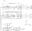
- FIG. 1is a schematic diagram illustrating the general layout and the key components that form part of an optical rangefinder instrument according to an example embodiment of the present invention
- FIG. 2depicts schematically an exemplary arrangement of 16 contiguous instantaneous fields of view (IFOVs) of an example multi-channel optical receiver;
- IFOVsinstantaneous fields of view
- FIG. 3is a graph that illustrates the drift of the center wavelength of the transmission bandpass of a typical optical interference filter as the incidence angle of the light impinging on the filter changes from 0° (normal incidence) to 30°;
- FIG. 4A , FIG. 4B , FIG. 4C and FIG. 4Dshow four different configurations of the multi-channel analog front end and digital acquisition.
- the optical rangefinder 10which operates according to the pulsed TOF principle, comprises an optical emitter 20 that emits trains of optical pulses having predetermined temporal and spatial characteristics. It also includes a multi-channel optical receiver (shortened as MCOR) 40 for detection of the optical return signals and their subsequent conversion into electrical waveforms. Each detection channel of the MCOR 40 outputs return signal waveforms that could contain at least one peak that stands out from noise.
- MCORmulti-channel optical receiver
- a return signal waveformis obtained after the emission of each light pulse by the optical emitter 20 , but it may happen that the waveform carries no useful information at a given moment.
- each peak present in a return signal waveformis a signature of an object currently located within the instantaneous field of view (IFOV) associated to the corresponding detection channel.
- IFOVinstantaneous field of view
- Several consecutive channelsmay generate waveforms containing exactly the same signature (also referred to as a pulse echo) when, for example, a large object is ranged (ex.: wall) or when an object gets in close proximity of the instrument.
- FIG. 1also shows that the output of the MCOR 40 connect to a control and processing unit (CPU) 60 that performs further processing of the return signal waveforms (after they have been converted into digital format by the Analog-to-Digital Converter (ADC) 80 ) and transmission of the output data to the data interface 70 .
- the CPU 60performs some other functions such as generating a pulse trigger signal that is forwarded to the optical emitter 20 for firing each light pulse.
- Synchronization trigger signal(in phase or shifted) is also sent to the MCOR 40 for starting the acquisition of the return signal waveforms.
- the CPUcontrols the acquisition by starting and stopping the waveform acquisition.
- the acquisition timeis determined by the maximum range to be covered by the optical rangefinder 10 .
- the optical rangefinder 10also includes means for supplying electrical power to the various subsystems depicted in FIG. 1 . For clarity, these power supplies have not been shown in FIG. 1 . Both optical emitter 20 and MCOR 40 will be described in further details in the next two sections.
- the optical emitter 20radiates very brief light pulses, each having for example a duration of a few ns, and this duration sets a lower bound for the width (duration) of the signatures that could be present in the return signal waveforms generated at the output of the MCOR 40 .
- the optical rangingshould be carried out using light pulses of a duration which is as short as possible.
- Such pairs of signaturescan be produced, for example, when two distinct objects are present within a given IFOV at the same moment, the objects being at slightly different distances from the rangefinder.
- the shortest duration that can be achieved for the light pulsesis limited by the impulse responses of both the driver electronics and the light source integrated in the optical emitter 20 .
- the signatures in the return signal waveformswill be faithful replicas of the emitted light pulses provided that the overall detection bandwidth of the MCOR 40 is high enough, generally in the range of a few tens to a few hundreds MHz.
- the spectrum of the emitted light pulseslies for example in the near-infrared region of the electromagnetic spectrum.
- Some factors favor the use of near-infrared lightsuch as the availability of affordable, compact optical sources and high-sensitivity photodetectors, the weaker response of the unaided human eye to near-infrared light, which makes the radiated light pulses non distracting, and the weaker solar irradiance background level in this spectral region as compared to the corresponding level in the visible wavelength region.
- Visible lightcan also be used for example when the need to illuminate the environment is required (global illumination or signaling information using light).
- At least one high-power light-emitting diode (LED) unitis used to form the LED source 22 of the optical emitter 20 .
- LED sourcesshare several desirable features of semiconductor laser diodes emitting in the same spectral region since they are very compact, rugged, solid-state devices that can be driven at high repetition rate with electrical current pulses of a few ns duration. As noted earlier, this latter feature is useful for suitable range resolution to any optical ranging instrument based on the pulsed TOF principle.
- High-power LEDsare currently available for emission at various center wavelengths in the near-infrared spectral region. Longer near-infrared wavelengths, such as 940 nm for example, may be useful because of the steady decrease exhibited by the solar irradiance spectrum in this region. As compared to their laser diode counterparts, LEDs emit over a much wider wavelength band, which typically attains 10 to 50 nm depending on the selected LED material and its drive level.
- the light emitted by LEDshas much lower temporal and spatial coherences than the light emitted by laser diode sources. Among other things, this means that the LED light impinging on an unprotected human eye and transmitted up to the eye retina will spread over a much larger spot on the retina. As a result, the light emitted from LEDs is much less hazardous than laser radiation of similar optical power level and wavelength in case of inadvertent ocular exposure events. In fact, the potential eye hazards that could result from exposure to the light emitted by LEDs are best assessed by performing hazard analyses based on the rules and guidelines given in safety standards intended for lamp devices.
- the safety standard now recommended when dealing with LED lightis the International Standard IEC 62471 Photobiological safety of lamps and lamp systems, First Edition, (2006-07), published by the International Electrotechnical Commission.
- the lower eye safety constraints of using LED lightallows for illumination with pulses of higher optical energy, thus increasing the detection performance of a rangefinder instrument without requiring any change to its optical receiver.
- light pulses of higher optical energyresult in optical return signals that better compete with any parasitic background light level captured by the MCOR 40 .
- the light emitted by the LED source 22can be optically conditioned to be spread over a desired field of illumination (FOI) by using for example a collimating lens assembly 24 followed by an optical diffuser 26 , as depicted in FIG. 1 .
- the collimating lens assembly 24could have a high input numerical aperture to promote better capture of the highly-diverging raw output light beam 28 emitted from the LED source 22 .
- the lens assembly 24redirects the captured light to form in its exit aperture plane a light irradiance distribution 30 having a transverse cross-section suited to the dimensions of the optical diffuser 26 .
- the lens assembly 24reduces the divergence angle of the emitted light beam 28 to a few degrees to ensure that the specified optical diffusing characteristics of the diffuser 26 will be met.
- the light beamis converted into an asymmetric light cone 32 having an opening (divergence) angle that defines the FOI of the optical emitter 20 .
- an optical diffuser 26facilitates the mounting of the LED source 22 .
- the spatial characteristics of the light beam 32 exiting from the diffuser 26are nearly insensitive to the exact disposition and alignment of the individual LED units integrated in the LED source 22 .
- holographic optical diffusershave peak optical transmissions which can reach 90% and even higher at the desired wavelength.
- holographic light-shaping diffuserscan be designed to spread the incoming light over a prescribed (asymmetric) FOI, which can have divergence angles that differ appreciably along both horizontal and vertical directions for best use in optical rangefinders intended for various applications. This type of optical diffuser is also appreciated for its nearly Gaussian-shaped, smooth output light irradiance distribution.
- a LED source 22can be integrated in the optical emitter 20 without any collimating lens assembly 24 or optical diffuser 26 when the intended application requires flooding light 32 over very wide FOIs (for example 120° or wider) that are symmetrical along both orthogonal transverse directions.
- FOIsfor example 120° or wider
- This cost-efficient approachis made possible due to the highly-diverging nature and smoothness of the raw output light emitted from LEDs.
- this approachallows for some tailoring of the resulting FOI by individually tuning the orientation of the center emission axis of each LED unit that forms part of the LED source 22 .
- a lenticular lens sheetcan substitute for the optical diffuser 26 .
- Lenticular lens sheetsgenerally consist of an extruded plastic sheet having one surface embossed with a set of linear tiny corrugations (called lenticules) running parallel to each other and acting as an array of magnifying lenses. Lenticular lenses are used for spreading light along a single transverse direction (perpendicular to the orientation of the lenticules), and can generate specific FOIs required by the intended applications.
- a LED reflectoris also another possibility to shape the light at a very low cost.
- the optical emitter 20also includes electronics 34 for driving the LED source 22 with current pulses having peak amplitude and duration suitable for effective implementation of the pulsed TOF principle.
- a pulsed voltage trigger signal generated by the CPU 60commands the generation of each current pulse by the LED driver electronics 34 .
- the optical pulsescan be emitted with durations typically below 50 ns.
- the duty cycle (relative ON time) of the optical emissioncan be as low as 0.1%.
- Driving the LED source 22 at low duty cycleallows for raising the peak current drive level at values that largely exceed the nominal current rating of the LED source 22 without compromising its lifetime.
- any reduction of the peak drive level of the LEDscan be compensated for by mounting additional LED sources 22 in the optical emitter 20 and appropriately duplicating their drive electronics 34 .
- the optical emitter 20may further benefit from the use of several LED sources 22 by performing individual alignment (optical boresighting) of each LED source 22 along a specific direction in such a way that the collective overlap of the radiated light beams results in a better filling (uniformity) of the FOI.
- This approachmay provide a uniform FOI having the desired overall dimensions without the use of an optical diffuser 26 .
- the optical detection and ranging of objects located within an overall FOV composed of a 1 ⁇ N linear arrangement of N smaller IFOVs extending along the horizontal directionis made possible with an optical receiver configuration 40 as shown in the schematic diagram of FIG. 1 .
- the horizontal planeis set parallel to the plane of the page.
- the reference X axisalso shown in FIG. 1 , is set horizontally along the direction perpendicular to the reference Z axis, the latter being parallel to the direction along which the optical axes of both optical emitter 20 and MCOR 40 point (i.e., parallel to the line of sight of the instrument 10 ).
- the Y axis, orthogonal to both X and Z axes,then points along the vertical direction. Referring temporarily to FIG.
- FIG. 2a front view of an exemplary linear arrangement of 16 separate IFOVs is schematically illustrated.
- the set of IFOVsis disposed along the horizontal X direction.
- the whole field of viewis enclosed within a field of illumination (FOI) generated by the optical emitter of the optical rangefinder instrument.
- FOIfield of illumination
- each individual IFOVhas different extents along the X and Y axes since these extents are determined by the dimensions of the photosensitive surface of each photodetector.
- FIG. 2shows a FOI having an elliptically-shaped outer contour (dashed line in FIG. 2 ) of sizeable eccentricity, namely with FOI X >>FOI Y , although various shapes can be envisioned for the FOI.
- the FOIis for example set wide enough to enclose the FOV of the MCOR 40 along both X and Y directions.
- FIG. 2illustrates an example embodiment that allows sensing over a FOV having a wide extent (FOV X ) along the horizontal direction, the sensing being realized without the need for any mechanical scanning means.
- the required horizontal extent FOV Xvaries with the intended application. For example, in automotive applications, it can attain around 15° in systems for pre-crash mitigation, 40° for blind-spot detection, and 85° in systems for parking assistance. In transportation applications like stop bar detection, wider FOV is preferred for shorter intersection with several lanes, narrower FOV for longer intersection. In all cases, objects having low surface reflectance at the emission wavelength of the instrument 10 should be reliably detected and ranged over relatively short distances.
- the expression “three-dimensional (3D) optical sensing”would be more appropriate in this situation due the ranging capability of the instrument that provides information about the location of any detected object along the third direction, parallel to the Z axis defined in the preceding paragraph.
- the arrangement of the IFOVsreflects the disposition of the set of photodetectors in the focal plane of the MCOR 40 .
- the optical return signal incident on the collecting aperture of the MCOR 40first passes through an optical filter 42 (optional) that blocks the portion of the parasitic background light having its wavelength spectrum out of a limited wavelength band determined by the emission spectrum of the optical emitter 20 .
- optical filter 42(optional) that blocks the portion of the parasitic background light having its wavelength spectrum out of a limited wavelength band determined by the emission spectrum of the optical emitter 20 .
- Optical interference filtersare useful due to their spectral bandpasses having steep edges and high optical transmission.
- the bandpass of the optical filter 42should be selected relatively wide, and in some circumstances it can be advisable to operate the MCOR 40 without any optical filter 42 . The rationale for such a practice is twofold.
- the filter bandpassshould be a bit wider than the emission spectrum of the optical emitter 20 to reduce the occurrence of rejection of the useful optical return signal incident on the collecting aperture.
- the second reasonpertains to the well-known drift of the center wavelength of narrowband interference optical filters as the incidence angle of the incoming light increases. This phenomenon is especially troublesome for optical instruments that sense over wide FOVs that, in extreme situations, can cover up to 80° on either side of the normal incidence direction.
- FIG. 3is a graph that illustrates the shift towards shorter wavelengths of the transmission bandpass of an exemplary optical interference filter 42 having a relatively wide bandwidth of about 80 nm FWHM. It is apparent that the center wavelength of the bandpass drifts from about 960 nm for a 0° incidence angle (curve 110 depicted in thick solid line) to about 930 nm for a 30° incidence angle, as shown by the curve 120 depicted in dashed line. The drift observed as the incidence angle opens up to 30° then means that an increasing part of the spectrum of the optical return signal will be blocked by the optical filter 42 as this signal comes from objects located away from the center position of the FOV.
- the graphalso shows the typical emission spectrum 130 of a 940-nm LED source depicted in thin solid line.
- the filterwas chosen so that its bandpass for normal incidence is well matched to the LED emission spectrum.
- FIG. 3also plots the curve 140 of the solar irradiance spectrum at sea level.
- a comparison of both solar irradiance and LED emission spectraillustrates an advantage of operating at an emission wavelength close to 940 nm since this wavelength region coincides with a sizeable dip in the solar irradiance spectrum. It is then necessary to widen the bandpass of the optical filter 42 to reduce the occurrence of any undesirable blocking of the optical return signal sensed over a wide FOV, with the unfortunate consequence of capturing more parasitic background light. This situation can impact on the selection of suitable photodetectors for integration in the MCOR 40 .
- the center wavelength of optical interference filtersalso shows some sensitivity to the ambient temperature.
- the optical filtering actioncan also be realized through the use of a commercially-available optical protection window having one of its faces coated with suitable optical films to block some parts of the optical wavelength spectrum.
- highly-resistant protection windowsmade from a material formulated to allow wavelength-selective optical transmission can be obtained from manufacturers such as Bayer AG Plastics Business Group (Leverkusen, Germany).
- their lightweight Makrolon® polycarbonate material model 2405 with color formulation 450601features high impact strength while effectively blocking light (nearly 0% transmittance) of wavelength lower than 700 nm.
- the part of the optical return signal passing through the optical filter 42is then transmitted through an objective 44 that focuses it onto the photosensitive surfaces of a series of photodetectors 46 disposed horizontally side-by-side in (or in close proximity of) the focal plane of the objective 44 .
- the objective 44may comprise a single lens element, as depicted schematically in FIG. 1 , or it may be embodied as an optical assembly comprising several lens elements.
- the objective 44can be built with minors or from a combination of minors and correcting lenses/plates, as it is found in catadioptric objective assemblies.
- Several factorsmay impact the design of the objective 44 such as the required f-number, its clear aperture diameter (which defines the collecting aperture of the MCOR 40 ), the level of correction required for the dominant optical aberrations, its compactness, ruggedness, and fabrication cost.
- the staring linear array of photodetectors 46comprises a plurality of individual photodetectors having for example identical characteristics.
- the photosensitive surface area of each photodetectordetermines its corresponding IFOV.
- the commercially-available 16-element linear array of silicon (Si) PIN photodiodes model S8558 from Hamamatsu Photonics (Hamamatsu City, Japan)features photosensitive surface areas of 0.7 mm (horizontal) by 2.0 mm (vertical) when the array is set horizontally (with an element pitch at 0.8 mm).
- the IFOV associated to each individual photodetectorhas dimensions of 0.8° (H) ⁇ 2.3° (V) when the linear array is coupled to an objective of 50-mm focal length.
- the 16-element linear array(including the gap) provides a full FOV of 14.5° (H) ⁇ 2.3° (V), which is then mostly elongated along the horizontal direction.
- Other manufacturersoffer linear arrays.
- Advanced Photonix(Camarillo, Calif.) supplies the PDB-C216 which is a 16-element linear array in which the dimension of each element is 1.22 mm (H) ⁇ 1.84 mm (V) and also supplies the PDB-C232 which is a 32-element linear array in which the dimension of each element is 0.89 mm (H) by 1.65 mm (V).
- a two-dimensional photodetector arraycould also be used, for example when some angular resolution along the vertical direction is desired.
- the 5 ⁇ 5 element SI PIN photodiode array number 57585 from Hamamatsu with an active area per element of 1.3 mm ⁇ 1.3 mm (with an element pitch at 1.5 mm)can be used.
- component S4204 from Hamamatsuis a dual-element photodiode, each element having an active area of 1 mm ⁇ 2 mm.
- component OPR2101is a 6-element photodiode array, each element having an active area of 0.72 mm ⁇ 1.23 mm. Its configuration is 2 ⁇ 2 elements in the middle, one additional element on each side of the 2 ⁇ 2 matrix.
- the example embodimentuses an array of PEN photodiodes in place of the more widely used APDs.
- the need for sensing over a wide FOV combined with the use of a LED-based optical emitter 20prevents the use of a narrowband optical interference filter in the MCOR 40 for optical suppression of the parasitic background light.
- an important solar background signalreaches the photodetectors 46 and competes with the useful optical return signal.
- the scene irradiance under bright sunlightcan reach 1000 W/m 2 . With an overcast sky, it can fall to approximately 100 W/m 2 .
- These outdoor conditionsare very different from artificially-illuminated indoor space where the irradiance is typically 5-30 W/m 2 .
- An examplecan be worked out to gain better insight about the solar background signal.
- an optical receiver configurationcomprising an objective of 20-mm clear aperture and having a focal length of 19.7 mm placed behind an optical filter having an 80-nm bandpass centered at the 940-nm wavelength, as suggested for sensing over wide FOVs.
- the optical power of the solar background signal within the optical filter bandwidth that is received on the photosensitive surface (here 0.7 ⁇ 2.0 mm 2 ) of a photodiode placed in the focal plane of the objectiveis estimated to range from about 80 nW to 800 nW as the angle between the line of sight of the optical receiver and the sun is reduced from 75° to 15° during clear-sky daytime conditions.
- the estimated solar background signalwould rise up to about 5 mW when direct sunlight is captured, i.e., when the line of sight of the instrument points right on the sun or when direct sunlight is deviated towards the instrument by a highly-reflecting flat surface.
- the resultis much higher and reaches approximately 15 uW for the same sensor configuration (80-nm bandpass and a surface of 0.7 ⁇ 2.0 mm 2 ).
- an optical filter or window made from a material formulated to allow wavelength-selective optical transmission above 700 nmis used (instead of using an 80-nm bandpass filter)
- the level of the backgroundcan be increased by a factor 10 (up to 8 uW to 150 uW).
- the level of the backgroundcan increase by a factor 16 (up to 13 uW to 240 uW).
- a PIN photodiode with a relatively large active areahas a reverse saturation current (Is) high enough to avoid saturation from this background illumination.
- the Is parametercan be 10 to 40 times higher than the APD in continuous operation. This large saturation current permits to detect very weak pulse signal in a very high ambient light. Indeed, tests have shown that, in most circumstances, the internal gain of APDs integrated in devices for outdoor use cannot be set higher than about 20 during daytime to avoid overload of the photodiodes or saturation of the detection electronics. In these conditions, operating APDs at low internal gain setting means that their unique performance characteristics are far from being fully exploited.
- APDsoperate under high bias voltages (varying typically between 100 V and 500 V) and their seamless stable operation in adverse outdoor conditions calls for means for stabilizing their junction temperature, which then impacts negatively on the cost of an instrument integrating this type of photodetectors.
- the circuit that generates the bias voltageshould be temperature stabilized due to the fact that APDs operated in linear regime are biased very close to their breakdown voltage, thus adding further to the cost of APD assemblies.
- the temperature dependence of APDs and of their related circuitryis discussed for example in U.S. Pat. No. 6,504,266.
- the high bias voltage of APDsalso means that a spacing (gap) should be created between consecutive photodiodes in the array.
- each photodiode of the 16-element linear APD array model AA16-9 DIL 18 available from Silicon Sensor GmbH (Berlin, Germany)features a photosensitive surface area of about 0.21 mm (H) ⁇ 0.65 mm (V), with a non sensitive gap of 0.11 mm (H) that separates consecutive photodetectors.
- Hmm
- V0.11 mm
- Operating such an APD array in the focal plane of a 50-mm objectivethen results in the presence of a blind zone covering 0.13° (along the horizontal) between each adjacent pair of IFOVs.
- each IFOV for this specific designcovers a horizontal extent of 0.24°. Stated otherwise, in this example about 35% of the horizontal extent of the whole FOV consists of blind zones in which objects would remain undetected.
- linear arrays of PINsare still far less expensive, thus favoring their integration in low-cost optical instruments intended for widespread use for several applications notably in mid or low-priced car vehicles.
- PIN photodiodescan be integrated with other technologies, as reported in U.S. Pat. No. 7,830,442. This means that linear arrays of PIN photodiodes (or 2D array) can be mounted with other semiconductor devices on a single die fabricated using various technologies, thus leading to highly-integrated, very compact, low-noise and economical multi-channel optical detection subassemblies.
- a Silicon-On-Insulator (SOI) CMOS processcan be used to produce PIN photodiodes.
- Hybrid technologycan also be used to integrate the PIN photodiode with a Read Out Integrated Circuit (ROIC).
- ROICRead Out Integrated Circuit
- a Si-PIN arraywill be integrated with the ROIC die in a standard IC packaging.
- the ROICconverts the photocurrents from the PIN array into voltages for the digitization and for the processing.
- the ROICcan integrate several Analog-to-Digital Converters (ADC) for parallel acquisition.
- ADCAnalog-to-Digital Converters
- Linear arrays of PIN photodiodesare available with photosensitive surface areas much larger than what can be obtained with linear arrays of APDs of comparable cost.
- using photodetectors of a larger formatis highly desirable since a given RN can be covered by placing an objective 44 of longer focal length in front of the photodetectors. Since the need for keeping the optical aberrations manageable sets a lower limit to the f-number of the objective, the possibility of selecting a longer focal length for the objective 44 then implies a higher clear aperture diameter for this component.
- selecting PIN photodiodes of a larger formatallows for capturing more optical return energy incident on the collecting aperture of the MCOR 40 for fixed values of the FOV and of the objective f-number.
- PIN photodiodesthen favor higher optical collection efficiency for the MCOR 40 , which can balance, at least partially, their lower sensitivity as compared to APD photodiodes.
- the lack of an internal gain mechanism in PIN photodiodescan be balanced by an optical gain resulting from the use of a wider collecting aperture.
- the stability of the photo sensitivity of the PIN arrayis useful when a reflection on the window of the enclosure of the emitter is used as a reference signal.
- This signalwill be more stable independently of the background level and can be useful to indicate the position of the window (reference distance) and the level of dust/dirt on the window (amplitude of this reflection).
- the MCOR 40 of an example embodiment of the optical ranging instrument 10also includes multi-channel analog front end electronics 48 for conditioning of the raw electrical current waveforms at the outputs of the linear array 46 of PIN phofothodes.
- exemplary analog front end electronics 48may consist of low-noise trans-impedance amplifiers, high-bandwidth amplifier stages, and low-voltage circuitry for biasing the linear array 46 of PIN photodiodes.
- the reverse voltage for biasing the PIN photodiodeis less than 50 V. Using a photodiode array with a relatively large active area element generally requires to set the reverse voltage (Vr) close to the maximum rating value.
- the analog outputs of the front end electronics 48are forwarded to a multi-channel analog-to-digital converter (ADC) board 80 that digitizes the analog voltage waveforms. Digitization at rates of several tens to hundreds of megasamples per second for each detection channel provides adequate distance resolution to help reduce the occurrence of wash out of the signatures that could be present in the return signal waveforms. It can be noted that the duration of the signatures remains nearly the same since the instrument 10 senses objects present within the FOV. This means that the sampling frequency of the ADC board 80 can be selected high enough to sample each signature with a convenient number of sampling points. The acquisition process can also use shifting techniques to decrease the sampling frequency of the ADC 80 . Some of these shifting techniques are described in U.S. patent application publication No. 2010/277,713.
- Signatures with very low peak amplitudescan be detected with a PIN-based optical detection configuration as described in the preceding paragraph.
- the noise floor of a PIN photodiode connected to suitable analog detection electronicscan be evaluated by first assuming return signal waveforms that contain signatures of about 20-ns duration FWHM, and that are amplified with analog electronics having a matched bandwidth of 50 MHz.
- PIN photodiodesare available with typical peak sensitivity of about 0.7 A/W and their noise contribution is negligible with respect to that of the front end analog electronics.
- the MAX3806 high-gain linear preamplifier developed for optical ranging applications and manufactured by Maxim Integrated Products (Sunnyvale, Calif.)features a typical noise floor density of 1.5 pA/Hz 1/2 .
- the noise floor of this analog electronicsis about 15 nW over the 50-MHz detection bandwidth.
- This noise floor contribution on the return signal waveformscan be reduced down to about 0.5 nW by averaging a set of 1024 successive return signal waveforms.
- This exampleshows that useful signatures that carry peak optical powers of only a few nW could be detected with suitable SNRs.
- the conditioning and transmission of the return signal waveforms from the PIN linear array 46 up to the CPU 60can also be realized through single-channel electronics and digital conversion without departing from the scope of the present invention.
- the N outputs of the PIN linear array 46would be interrogated in sequence (time multiplexing) and then amplified by a single-channel analog amplifier chain prior to transmitting serially the set of return signal waveforms to a single-channel ADC 80 for conversion into digital format.
- This single-channel embodiment for the analog front end electronics 48 and ADC 80is more economical than its multi-channel counterpart, but generates the emission of N successive light pulses from the optical emitter 20 for each complete interrogation cycle of the PIN linear array 46 .
- the optical emitter 20can be designed for firing light pulses at repetition rates of several tens to hundreds of kHz. The duration of the interrogation cycles can then be kept short enough for enabling optical sensing in real-time.
- FIG. 4shows four different embodiments of the multi-channel analog front end and digital acquisition.
- FIG. 4Ashows a Photodiode Array (N elements) with a reverse bias voltage Vr 100 .
- Photodiode Array 46has a common pin (anode or cathode) supplied by the Vr 100 .
- Each element (channel) of the Photodiode Array 46is conditioned by the Analog Front-end 48 and digitalized by the ADC 80 in parallel. Signals from each element of the Photodiode Array 46 can be AC coupled (all the DC level from the background illumination is rejected) or DC coupled.
- FIG. 4Ashows a Photodiode Array (N elements) with a reverse bias voltage Vr 100 .
- Photodiode Array 46has a common pin (anode or cathode) supplied by the Vr 100 .
- Each element (channel) of the Photodiode Array 46is conditioned by the Analog Front-end 48 and digitalized by
- FIG. 4Binserts a multiplexer, Mux 102 , controlled by the Control and processing unit (not shown) to minimize the number of ADC channels (at least one channel).
- FIG. 4Cshows a configuration using a MUX 102 between the Photodiode Array 46 and the Analog Front end 48 .
- the number of Analog Front-end channelscan be decreased to one thus reducing the number of components in the Analog front-end.
- the Mux 102is placed in a very sensitive area and the “ON” resistance and channel input and output capacitance should be low. Parasitic capacitance can limit the bandwidth
- FIG. 4Dshows a configuration with a Mux 102 placed between the reverse bias voltage Vr 100 and the Photodiode Array 46 . This configuration is less sensitive to capacitance of the multiplexer but should operate with the level of the reverse bias voltage.
- the Control and Processing Unit(CPU)
- the set of time-series numerical data streams at the output of the ADC board 80i.e., the set of digitized return signal waveforms, is forwarded to the CPU 60 for further processing.
- the heart of the CPU 60is for example a microprocessor assembly suited for embarked applications and capable of performing parallel processing with the required number of channels.
- CPU 60can also revolve around other types of processing means such as a FPGA (Field-Programmable Gate Array), a DSP (Digital Signal Processor) or other programmable logics. The nature and extent of the numerical processing depend on the intended application.
- the CPU 60can then communicate the output data to a higher-level system in which the optical rangefinder 10 can be integrated via a data interface 70 that operates under exemplary data communication interfaces such as Ethernet, USB or CANbus.
- the optical rangefinder instrument 10can be considered to be a full waveform LIDAR (LIght Detection And Ranging) instrument since it can output a set of digitized return signal waveforms acquired during a suitable time interval dictated by the maximum range at which objects are to be detected and ranged.
- LIDARLIght Detection And Ranging
- full-waveform instrumentsprovide greater flexibility by allowing a host of numerical processing tasks to be done on the recorded digital waveforms.
- the signal-to-noise ratio (SNR) of the signatures possibly present in the return signal waveforms associated to any given detection channelcan be enhanced by averaging a number of successive waveforms acquired by the channel.
- SNRs obtained by standard signal averaging (accumulation)are possible provided that the noise contributions present in the successive waveforms are independent from each other and fully uncorrelated.
- the SNR of the waveformscan be increased by a factor of (n W ) 1/2 , where n W is the number of averaged waveforms.
- Another condition that limits the number of waveforms to be averagedis the need for stationarity of the processes that generate the signatures.
- the properties (peak amplitude, shape, time/distance location) of the signatures present in the waveformsshould remain unchanged during the time period required to record a complete set of waveforms that will be averaged. This condition may be difficult to respect when attempting to detect objects that move rapidly with respect to the optical rangefinder 10 .
- the signatures associated to moving objectsdrift more or less appreciably from waveform to waveform. Although this situation frequently occurs in the applications to which to optical rangefinder 10 described herein is intended, its detrimental impacts can be alleviated by selecting the pulse repetition rate of the optical emitter 20 high enough, for example in the kHz range.
- the waveform averagingcan be implemented in the form of mobile averaging, wherein the current average waveform is continuously updated by summing it with a newly-acquired waveform while subtracting from the average the waveform that was first acquired.
- mobile averagesdoes not impact on the rate at which the output detection data is generated by the CPU.
- a timely detection of any object appearing suddenly in the FOV of the optical ranging instrument 10can be enabled by resetting the mobile average when a newly-acquired waveform presents at least one feature that differs appreciably from the current average waveform.
- the optical rangefinder instrument of the present inventioncan thus be integrated in fixed systems dedicated to traffic monitoring, for example at road intersections where various types of objects (vehicles, bicycles, pedestrians, pavement) should be reliably detected over wide fields of view in various weather conditions and under widely-varying lighting conditions occurring from both natural and artificial sources. It can also be integrated in a mobile application such as in driver assistance applications in the automotive field of industry.
Landscapes
- Physics & Mathematics (AREA)
- Engineering & Computer Science (AREA)
- Electromagnetism (AREA)
- General Physics & Mathematics (AREA)
- Radar, Positioning & Navigation (AREA)
- Remote Sensing (AREA)
- Computer Networks & Wireless Communication (AREA)
- Optical Radar Systems And Details Thereof (AREA)
- Measurement Of Optical Distance (AREA)
Abstract
Description
Claims (49)
Priority Applications (1)
| Application Number | Priority Date | Filing Date | Title |
|---|---|---|---|
| US16/192,193USRE48763E1 (en) | 2011-05-11 | 2018-11-15 | Multiple-field-of-view scannerless optical rangefinder in high ambient background light |
Applications Claiming Priority (3)
| Application Number | Priority Date | Filing Date | Title |
|---|---|---|---|
| US13/105,497US8908159B2 (en) | 2011-05-11 | 2011-05-11 | Multiple-field-of-view scannerless optical rangefinder in high ambient background light |
| US15/373,189USRE47134E1 (en) | 2011-05-11 | 2016-12-08 | Multiple-field-of-view scannerless optical rangefinder in high ambient background light |
| US16/192,193USRE48763E1 (en) | 2011-05-11 | 2018-11-15 | Multiple-field-of-view scannerless optical rangefinder in high ambient background light |
Related Parent Applications (1)
| Application Number | Title | Priority Date | Filing Date |
|---|---|---|---|
| US13/105,497ReissueUS8908159B2 (en) | 2011-05-11 | 2011-05-11 | Multiple-field-of-view scannerless optical rangefinder in high ambient background light |
Publications (1)
| Publication Number | Publication Date |
|---|---|
| USRE48763E1true USRE48763E1 (en) | 2021-10-05 |
Family
ID=47139749
Family Applications (3)
| Application Number | Title | Priority Date | Filing Date |
|---|---|---|---|
| US13/105,497CeasedUS8908159B2 (en) | 2011-05-11 | 2011-05-11 | Multiple-field-of-view scannerless optical rangefinder in high ambient background light |
| US15/373,189Active2032-09-15USRE47134E1 (en) | 2011-05-11 | 2016-12-08 | Multiple-field-of-view scannerless optical rangefinder in high ambient background light |
| US16/192,193Active2032-09-15USRE48763E1 (en) | 2011-05-11 | 2018-11-15 | Multiple-field-of-view scannerless optical rangefinder in high ambient background light |
Family Applications Before (2)
| Application Number | Title | Priority Date | Filing Date |
|---|---|---|---|
| US13/105,497CeasedUS8908159B2 (en) | 2011-05-11 | 2011-05-11 | Multiple-field-of-view scannerless optical rangefinder in high ambient background light |
| US15/373,189Active2032-09-15USRE47134E1 (en) | 2011-05-11 | 2016-12-08 | Multiple-field-of-view scannerless optical rangefinder in high ambient background light |
Country Status (6)
| Country | Link |
|---|---|
| US (3) | US8908159B2 (en) |
| EP (1) | EP2707748B1 (en) |
| JP (2) | JP2014517921A (en) |
| CN (1) | CN103502841B (en) |
| CA (1) | CA2833435C (en) |
| WO (1) | WO2012153309A2 (en) |
Cited By (4)
| Publication number | Priority date | Publication date | Assignee | Title |
|---|---|---|---|---|
| US11668830B1 (en) | 2018-06-01 | 2023-06-06 | Vayavision Sensing Ltd. | System and method for performing active distance measurements |
| US11725956B2 (en) | 2015-04-01 | 2023-08-15 | Vayavision Sensing Ltd. | Apparatus for acquiring 3-dimensional maps of a scene |
| US12093834B2 (en) | 2019-09-22 | 2024-09-17 | Vaya Vision Sensing Ltd. | Methods and systems for training and validating a perception system |
| US12428020B2 (en) | 2019-09-22 | 2025-09-30 | Vayavision Sensing Ltd. | Functional safety in autonomous driving |
Families Citing this family (122)
| Publication number | Priority date | Publication date | Assignee | Title |
|---|---|---|---|---|
| USRE46672E1 (en) | 2006-07-13 | 2018-01-16 | Velodyne Lidar, Inc. | High definition LiDAR system |
| US8908159B2 (en)* | 2011-05-11 | 2014-12-09 | Leddartech Inc. | Multiple-field-of-view scannerless optical rangefinder in high ambient background light |
| EP2721593B1 (en) | 2011-06-17 | 2017-04-05 | Leddartech Inc. | System and method for traffic side detection and characterization |
| CA2865733C (en) | 2012-03-02 | 2023-09-26 | Leddartech Inc. | System and method for multipurpose traffic detection and characterization |
| US9575180B2 (en)* | 2012-09-13 | 2017-02-21 | Mbda Uk Limited | Room occupancy sensing apparatus and method |
| DE102013003515A1 (en)* | 2013-03-04 | 2014-09-04 | Jenoptik Robot Gmbh | Method for measuring speed of moving object, particularly vehicle by using laser device, involves deriving velocity of moving object from change of coordinates of pairs of measurement data by pulses that are generated by transmitting device |
| EP2797227B1 (en)* | 2013-04-24 | 2018-07-11 | Ams Ag | Signal conditioning circuit for a light sensor, a sensor arrangement and a method for signal conditioning for a light sensor |
| JP6214993B2 (en)* | 2013-10-11 | 2017-10-18 | 株式会社キーエンス | Photoelectric sensor |
| US10203399B2 (en) | 2013-11-12 | 2019-02-12 | Big Sky Financial Corporation | Methods and apparatus for array based LiDAR systems with reduced interference |
| US9360554B2 (en) | 2014-04-11 | 2016-06-07 | Facet Technology Corp. | Methods and apparatus for object detection and identification in a multiple detector lidar array |
| CN104018995B (en)* | 2014-05-15 | 2016-08-24 | 上海泰胜风能装备股份有限公司 | Infrared distance measuring device |
| JP6449584B2 (en) | 2014-08-04 | 2019-01-09 | 株式会社トプコン | Angle detection device, surveying device |
| US10466460B2 (en)* | 2014-08-13 | 2019-11-05 | Surgivance Inc. | Line-scanning, sample-scanning, multimodal confocal microscope |
| JP6938371B2 (en)* | 2014-09-09 | 2021-09-22 | レッダーテック インコーポレイテッド | Discretization of detection zones |
| JP2016080572A (en)* | 2014-10-20 | 2016-05-16 | 朝日航洋株式会社 | Laser measurement system |
| US10393517B2 (en)* | 2014-10-27 | 2019-08-27 | Laser Technology, Inc. | Laser source modification techniques for a laser-based rangefinding or speed measurement instrument enabling increased range with improved accuracy |
| US9978887B2 (en)* | 2014-10-28 | 2018-05-22 | Silicon Laboratories Inc. | Light detector using an on-die interference filter |
| DE102015100910A1 (en)* | 2015-01-22 | 2016-07-28 | Valeo Schalter Und Sensoren Gmbh | Device and method for detecting objects for a motor vehicle |
| US10036801B2 (en) | 2015-03-05 | 2018-07-31 | Big Sky Financial Corporation | Methods and apparatus for increased precision and improved range in a multiple detector LiDAR array |
| EP3118651B1 (en)* | 2015-07-17 | 2021-04-21 | Hexagon Technology Center GmbH | Time-of-flight measuring device and time-of-flight measuring method with ambiguity solution in real time |
| KR102422784B1 (en)* | 2015-08-03 | 2022-07-19 | 엘지이노텍 주식회사 | Apparatus for light detection and ranging |
| US9992477B2 (en) | 2015-09-24 | 2018-06-05 | Ouster, Inc. | Optical system for collecting distance information within a field |
| US10063849B2 (en) | 2015-09-24 | 2018-08-28 | Ouster, Inc. | Optical system for collecting distance information within a field |
| US10397546B2 (en)* | 2015-09-30 | 2019-08-27 | Microsoft Technology Licensing, Llc | Range imaging |
| EP3165876A3 (en)* | 2015-11-03 | 2017-07-26 | Hexagon Technology Center GmbH | Opto-electronic measuring device |
| DE102015120534A1 (en)* | 2015-11-26 | 2017-06-01 | Valeo Schalter Und Sensoren Gmbh | Arrangement of at least one optical receiver of a transmitting and receiving device of an operating according to a light pulse transit time method optical measuring device |
| US10627490B2 (en) | 2016-01-31 | 2020-04-21 | Velodyne Lidar, Inc. | Multiple pulse, LIDAR based 3-D imaging |
| US9866816B2 (en) | 2016-03-03 | 2018-01-09 | 4D Intellectual Properties, Llc | Methods and apparatus for an active pulsed 4D camera for image acquisition and analysis |
| EP3430428B1 (en) | 2016-03-19 | 2025-04-02 | Velodyne Lidar USA, Inc. | Integrated illumination and detection for lidar based 3-d imaging |
| WO2017210418A1 (en) | 2016-06-01 | 2017-12-07 | Velodyne Lidar, Inc. | Multiple pixel scanning lidar |
| CA3035094A1 (en) | 2016-08-24 | 2018-03-01 | Ouster, Inc. | Optical system for collecting distance information within a field |
| WO2018040003A1 (en)* | 2016-08-31 | 2018-03-08 | 深圳市速腾聚创科技有限公司 | Three-dimensional laser radar |
| CN106291574B (en)* | 2016-09-10 | 2019-04-02 | 北醒(北京)光子科技有限公司 | A kind of Minitype infrared range unit |
| US10396117B2 (en)* | 2016-10-14 | 2019-08-27 | Waymo Llc | Optical receiver systems and devices with detector array including a plurality of substrates disposed in an edge to edge array |
| DE102016222092A1 (en)* | 2016-11-10 | 2018-05-17 | Osram Gmbh | TOF CAMERA, MOTOR VEHICLE, METHOD FOR MANUFACTURING A TOF CAMERA, AND METHOD FOR DETERMINING A DISTANCE TO AN OBJECT |
| CN108072877A (en)* | 2016-11-10 | 2018-05-25 | 光宝电子(广州)有限公司 | Optical devices |
| US10845470B2 (en) | 2016-11-16 | 2020-11-24 | Waymo Llc | Methods and systems for protecting a light detection and ranging (LIDAR) device |
| US10554881B2 (en) | 2016-12-06 | 2020-02-04 | Microsoft Technology Licensing, Llc | Passive and active stereo vision 3D sensors with variable focal length lenses |
| US10469758B2 (en) | 2016-12-06 | 2019-11-05 | Microsoft Technology Licensing, Llc | Structured light 3D sensors with variable focal length lenses and illuminators |
| KR102216690B1 (en)* | 2016-12-13 | 2021-02-17 | 한국전자기술연구원 | Lidar Apparatus |
| US20180172807A1 (en)* | 2016-12-20 | 2018-06-21 | Analog Devices Global | Method of Providing Enhanced Range Accuracy |
| EP4123285A1 (en)* | 2016-12-22 | 2023-01-25 | Ventana Medical Systems, Inc. | System and method for sample processing |
| US10690754B2 (en) | 2016-12-23 | 2020-06-23 | Cepton Technologies, Inc. | Scanning apparatuses and methods for a lidar system |
| US10520592B2 (en)* | 2016-12-31 | 2019-12-31 | Waymo Llc | Light detection and ranging (LIDAR) device with an off-axis receiver |
| CN107076853B (en)* | 2017-01-23 | 2019-02-19 | 深圳市大疆创新科技有限公司 | TOF ranging system and movable platform |
| JP6766185B2 (en)* | 2017-01-27 | 2020-10-07 | パイオニア株式会社 | Detection device, method for detecting the distance to an object, program and storage medium |
| DE102017101945A1 (en)* | 2017-02-01 | 2018-08-02 | Osram Opto Semiconductors Gmbh | Measuring arrangement with an optical transmitter and an optical receiver |
| DE102017106380B4 (en)* | 2017-03-24 | 2021-10-07 | Sick Ag | Optoelectronic sensor and method for detecting objects |
| EP3593166B1 (en) | 2017-03-31 | 2024-04-17 | Velodyne Lidar USA, Inc. | Integrated lidar illumination power control |
| EP3395875B2 (en) | 2017-04-24 | 2023-01-25 | Covestro Deutschland AG | Laser beam-permeable substrate material for sensor applications |
| DE102017207317B4 (en)* | 2017-05-02 | 2022-03-03 | Fraunhofer-Gesellschaft zur Förderung der angewandten Forschung e.V. | Device for determining a distance to an object and a corresponding method |
| CN110809704B (en)* | 2017-05-08 | 2022-11-01 | 威力登激光雷达美国有限公司 | LIDAR data acquisition and control |
| DE202018006696U1 (en) | 2017-05-15 | 2022-04-01 | Ouster, Inc. | Optical image transmitter with brightness improvement |
| US11112494B2 (en)* | 2017-05-18 | 2021-09-07 | Sharp Kabushiki Kaisha | Photodetector and portable electronic equipment |
| JP6788737B2 (en)* | 2017-05-19 | 2020-11-25 | シャープ株式会社 | Optical sensors and electronic devices |
| US11428790B2 (en)* | 2017-06-05 | 2022-08-30 | Texas Instruments Incorporated | Narrowband TIA and signaling for optical distance measurement systems |
| US20190066504A1 (en)* | 2017-06-18 | 2019-02-28 | George Zaloom | System for automatically determining the position and velocity of objects |
| EP3438699A1 (en) | 2017-07-31 | 2019-02-06 | Hexagon Technology Center GmbH | Range finder using spad arrangement for acquiring multiple targets |
| KR102050632B1 (en) | 2017-08-02 | 2019-12-03 | 주식회사 에스오에스랩 | Multi-channel LiDAR sensor module |
| KR102020038B1 (en)* | 2017-08-02 | 2019-09-10 | 주식회사 에스오에스랩 | LiDAR sensor module |
| US10852438B2 (en) | 2017-08-21 | 2020-12-01 | Caterpillar Inc. | LIDAR waveform classification |
| DE102017214702B4 (en)* | 2017-08-23 | 2022-08-11 | Robert Bosch Gmbh | LIDAR device for optically capturing a field of view |
| CN111033301A (en)* | 2017-08-31 | 2020-04-17 | 深圳市大疆创新科技有限公司 | Solid state light detection and ranging (LIDAR) system |
| CN111095018B (en) | 2017-08-31 | 2022-03-29 | 深圳市大疆创新科技有限公司 | Solid state light detection and ranging (LIDAR) systems, systems and methods for improving solid state light detection and ranging (LIDAR) resolution |
| JP6962748B2 (en)* | 2017-08-31 | 2021-11-05 | 日本信号株式会社 | Detection device |
| US10746875B2 (en)* | 2017-09-08 | 2020-08-18 | Osram Opto Semiconductors Gmbh | Sensor system and method to operate a sensor system |
| EP4220230B1 (en)* | 2017-09-26 | 2025-03-26 | Innoviz Technologies Ltd. | Lidar systems and methods |
| WO2019069260A1 (en)* | 2017-10-03 | 2019-04-11 | Leddartech Inc. | Full waveform multi-pulse optical rangefinder instrument |
| US10436953B2 (en) | 2017-12-01 | 2019-10-08 | Rockwell Automation Technologies Inc. | Arched collimating lens forming a disk-like illumination |
| US10690773B2 (en)* | 2017-12-07 | 2020-06-23 | Velodyne Lidar, Inc. | Systems and methods for efficient multi-return light detectors |
| US11353556B2 (en) | 2017-12-07 | 2022-06-07 | Ouster, Inc. | Light ranging device with a multi-element bulk lens system |
| US11294041B2 (en)* | 2017-12-08 | 2022-04-05 | Velodyne Lidar Usa, Inc. | Systems and methods for improving detection of a return signal in a light ranging and detection system |
| EP3729127B1 (en)* | 2017-12-21 | 2025-01-15 | Covestro Deutschland AG | Device made up of a multilayer body and a lidar sensor |
| CN108226948A (en)* | 2018-03-09 | 2018-06-29 | 北京理工大学 | A kind of three-dimensional solid-state face battle array laser radar and its distance measuring method |
| US10884105B2 (en) | 2018-05-31 | 2021-01-05 | Eagle Technology, Llc | Optical system including an optical body with waveguides aligned along an imaginary curved surface for enhanced beam steering and related methods |
| CN108957465B (en)* | 2018-06-07 | 2022-05-20 | 北京理工大学 | Pulse laser detection device that many first special-shaped photosurfaces received |
| WO2019245719A1 (en)* | 2018-06-21 | 2019-12-26 | Oyla, Inc | Device and method of optical range imaging |
| US11536805B2 (en) | 2018-06-25 | 2022-12-27 | Silc Technologies, Inc. | Optical switching for tuning direction of LIDAR output signals |
| RU2684445C1 (en)* | 2018-06-26 | 2019-04-09 | Федеральное государственное унитарное предприятие "Центральный научно-исследовательский институт химии и механики" (ФГУП "ЦНИИХМ") | Distance measuring device |
| CN117492019A (en) | 2018-07-31 | 2024-02-02 | 马克西姆综合产品公司 | Time-of-flight sensor and sensing method |
| US11385336B2 (en) | 2018-07-31 | 2022-07-12 | Maxim Integrated Products, Inc. | Time of flight sensors and sensing methods |
| US10760957B2 (en) | 2018-08-09 | 2020-09-01 | Ouster, Inc. | Bulk optics for a scanning array |
| US10739189B2 (en) | 2018-08-09 | 2020-08-11 | Ouster, Inc. | Multispectral ranging/imaging sensor arrays and systems |
| US10609266B2 (en) | 2018-08-21 | 2020-03-31 | Rockwell Automation Technologies, Inc. | Camera for wide field of view with an arbitrary aspect ratio |
| US11971507B2 (en) | 2018-08-24 | 2024-04-30 | Velodyne Lidar Usa, Inc. | Systems and methods for mitigating optical crosstalk in a light ranging and detection system |
| US11333748B2 (en)* | 2018-09-17 | 2022-05-17 | Waymo Llc | Array of light detectors with corresponding array of optical elements |
| US10712434B2 (en) | 2018-09-18 | 2020-07-14 | Velodyne Lidar, Inc. | Multi-channel LIDAR illumination driver |
| US11237256B2 (en)* | 2018-09-19 | 2022-02-01 | Waymo Llc | Methods and systems for dithering active sensor pulse emissions |
| WO2020083661A1 (en)* | 2018-10-23 | 2020-04-30 | Covestro Deutschland Ag | Ir-transparent sensor and camera system for motor vehicles |
| US11808887B2 (en)* | 2018-11-02 | 2023-11-07 | Waymo Llc | Methods and systems for mapping retroreflectors |
| US11082010B2 (en) | 2018-11-06 | 2021-08-03 | Velodyne Lidar Usa, Inc. | Systems and methods for TIA base current detection and compensation |
| US10877134B2 (en)* | 2018-11-19 | 2020-12-29 | Baidu Usa Llc | LIDAR peak detection using splines for autonomous driving vehicles |
| WO2020109007A1 (en) | 2018-11-29 | 2020-06-04 | Covestro Deutschland Ag | Lidar sensor system having improved surface quality |
| US11385335B2 (en) | 2018-12-07 | 2022-07-12 | Beijing Voyager Technology Co., Ltd | Multi-threshold LIDAR detection |
| RU194537U1 (en)* | 2018-12-21 | 2019-12-13 | Открытое Акционерное Общество "Пеленг" | DEVICE FOR CONTROL OF A LASER DANGER |
| CN113454483A (en)* | 2018-12-21 | 2021-09-28 | 旭硝子欧洲玻璃公司 | Laser radar detection device with releasable protective layer |
| US11885958B2 (en) | 2019-01-07 | 2024-01-30 | Velodyne Lidar Usa, Inc. | Systems and methods for a dual axis resonant scanning mirror |
| US12061263B2 (en) | 2019-01-07 | 2024-08-13 | Velodyne Lidar Usa, Inc. | Systems and methods for a configurable sensor system |
| EP3899575A4 (en)* | 2019-01-31 | 2022-08-31 | Sense Photonics, Inc. | STROBE DEPENDENT LIGHTING FOR FLASH LIDAR |
| US12429569B2 (en) | 2019-05-17 | 2025-09-30 | Silc Technologies, Inc. | Identification of materials illuminated by LIDAR systems |
| US11650317B2 (en) | 2019-06-28 | 2023-05-16 | Silc Technologies, Inc. | Use of frequency offsets in generation of LIDAR data |
| US10613203B1 (en) | 2019-07-01 | 2020-04-07 | Velodyne Lidar, Inc. | Interference mitigation for light detection and ranging |
| CN110412594A (en)* | 2019-07-22 | 2019-11-05 | 北京光勺科技有限公司 | A laser multi-channel detection system |
| DE102019122566A1 (en)* | 2019-08-22 | 2021-02-25 | Valeo Schalter Und Sensoren Gmbh | Method for operating an optoelectronic detection device and optoelectronic detection device |
| JP2021068795A (en) | 2019-10-23 | 2021-04-30 | ソニーセミコンダクタソリューションズ株式会社 | Light source device |
| CN110726983A (en)* | 2019-10-24 | 2020-01-24 | 深圳市镭神智能系统有限公司 | Laser radar |
| EP4058821A1 (en) | 2019-11-14 | 2022-09-21 | Covestro Intellectual Property GmbH & Co. KG | Thermoplastic compositino for lidar sensor system with improved absorption properties |
| US11774564B2 (en)* | 2020-02-06 | 2023-10-03 | Aptiv Technologies Limited | Low-cost readout module for a lidar system |
| EP3933790B1 (en)* | 2020-06-29 | 2023-07-05 | Haltian Oy | Apparatus for counting objects |
| US11828853B2 (en) | 2020-07-21 | 2023-11-28 | Leddartech Inc. | Beam-steering device particularly for LIDAR systems |
| CA3125623C (en) | 2020-07-21 | 2023-06-27 | Leddartech Inc. | Beam-steering device particularly for lidar systems |
| US11402510B2 (en) | 2020-07-21 | 2022-08-02 | Leddartech Inc. | Systems and methods for wide-angle LiDAR using non-uniform magnification optics |
| US11569834B2 (en) | 2020-07-28 | 2023-01-31 | AyDeeKay LLC | Time-interleaved dynamic-element matching analog-to-digital converter |
| KR102861681B1 (en)* | 2020-07-29 | 2025-09-18 | 엘지이노텍 주식회사 | Distance measuring camera |
| US12306344B1 (en)* | 2020-08-25 | 2025-05-20 | Silc Technologies, Inc. | Reduction of components in LIDAR systems |
| CN113109836B (en)* | 2020-09-28 | 2025-03-11 | 黄海容 | A multi-directional obstacle detection device |
| US11841516B2 (en) | 2020-11-13 | 2023-12-12 | Lg Innotek Co., Ltd. | Anamorphic receiver optical design for LIDAR line sensors |
| CN112817002A (en)* | 2021-01-29 | 2021-05-18 | 宁波飞芯电子科技有限公司 | Distance detection system and image acquisition module comprising same |
| US12411213B2 (en) | 2021-10-11 | 2025-09-09 | Silc Technologies, Inc. | Separation of light signals in a LIDAR system |
| WO2023137565A1 (en)* | 2022-01-24 | 2023-07-27 | Leddartech Inc. | System and method for optical signal spectrum management, in particular for lidar |
| US11519723B1 (en)* | 2022-04-06 | 2022-12-06 | King Fahd University Of Petroleum And Minerals | Digital counting and display system for a laser rangefinder |
| US12422618B2 (en) | 2022-10-13 | 2025-09-23 | Silc Technologies, Inc. | Buried taper with reflecting surface |
Citations (259)
| Publication number | Priority date | Publication date | Assignee | Title |
|---|---|---|---|---|
| US3680085A (en) | 1969-01-21 | 1972-07-25 | Giovanni Del Signore | Anti-collision apparatus for vehicles |
| US4533242A (en)* | 1982-09-28 | 1985-08-06 | The United States Of America As Represented By The Administrator Of The National Aeronautics And Space Administration | Ranging system which compares an object-reflected component of a light beam to a reference component of the light beam |
| WO1987005138A1 (en) | 1986-02-19 | 1987-08-27 | George Beggs | Object detection method and apparatus employing electro-optics |
| US4717862A (en) | 1984-11-19 | 1988-01-05 | The United States Government As Represented By The Secretary Of The Navy | Pulsed illumination projector |
| US4808997A (en) | 1987-05-21 | 1989-02-28 | Barkley George J | Photoelectric vehicle position indicating device for use in parking and otherwise positioning vehicles |
| EP0318260A2 (en) | 1987-11-27 | 1989-05-31 | Combustion Developments Limited | Monitoring means |
| US4891624A (en) | 1987-06-12 | 1990-01-02 | Stanley Electric Co., Ltd. | Rearward vehicle obstruction detector using modulated light from the brake light elements |
| JPH0259608A (en) | 1988-08-25 | 1990-02-28 | Matsushita Electric Ind Co Ltd | Vehicle ranging equipment and vehicles |
| US4928232A (en) | 1988-12-16 | 1990-05-22 | Laser Precision Corporation | Signal averaging for optical time domain relectometers |
| WO1992003808A1 (en) | 1990-08-17 | 1992-03-05 | The Secretary Of State For Defence In Her Britannic Majesty's Government Of The United Kingdom Of Great Britain And Northern Ireland | Surveillance apparatus particularly for use in viewing vehicle number-plates |
| EP0476562A2 (en) | 1990-09-19 | 1992-03-25 | Hitachi, Ltd. | Method and apparatus for controlling moving body and facilities |
| JPH0414390Y2 (en) | 1987-02-24 | 1992-03-31 | ||
| US5102218A (en) | 1991-08-15 | 1992-04-07 | The United States Of America As Represented By The Secretary Of The Air Force | Target-aerosol discrimination by means of digital signal processing |
| JPH04145391A (en) | 1990-10-05 | 1992-05-19 | Mitsubishi Electric Corp | Distance measuring device |
| JPH04172285A (en) | 1990-11-02 | 1992-06-19 | Mitsubishi Electric Corp | Distance measuring apparatus |
| US5134393A (en) | 1990-04-02 | 1992-07-28 | Henson H Keith | Traffic control system |
| EP0498815A1 (en) | 1989-10-26 | 1992-08-19 | Lohja Corp | Process for producing an active fine aggregate for the preparation of concrete. |
| US5179286A (en) | 1990-10-05 | 1993-01-12 | Mitsubishi Denki K.K. | Distance measuring apparatus receiving echo light pulses |
| US5198657A (en) | 1992-02-05 | 1993-03-30 | General Atomics | Integrated imaging and ranging lidar receiver |
| GB2264411A (en) | 1992-02-13 | 1993-08-25 | Roke Manor Research | Active infrared vehicle detector system |
| FR2690519A1 (en) | 1992-04-23 | 1993-10-29 | Est Centre Etu Tech Equipement | Road traffic speed and distance monitoring system - uses pair of optical transceivers and ultra-sonic telemetry |
| US5270780A (en)* | 1991-09-13 | 1993-12-14 | Science Applications International Corporation | Dual detector lidar system and method |
| US5317311A (en) | 1988-11-14 | 1994-05-31 | Martell David K | Traffic congestion monitoring system |
| EP0612049A1 (en) | 1993-02-15 | 1994-08-24 | STN ATLAS Elektronik GmbH | Method for classifying vehicles passing a predetermined point on the road |
| US5357331A (en) | 1991-07-02 | 1994-10-18 | Flockencier Stuart W | System for processing reflected energy signals |
| US5381155A (en) | 1993-12-08 | 1995-01-10 | Gerber; Eliot S. | Vehicle speeding detection and identification |
| US5389921A (en) | 1993-05-17 | 1995-02-14 | Whitton; John M. | Parking lot apparatus and method |
| DE19604338A1 (en) | 1995-02-18 | 1996-08-29 | Univ Dresden Tech | Vehicle counting and classification sensor |
| WO1996034252A1 (en) | 1995-04-28 | 1996-10-31 | Schwartz Electro-Optics, Inc. | Intelligent vehicle highway system sensor and method |
| DE29617413U1 (en) | 1996-10-07 | 1996-11-21 | Mekra Lang Gmbh & Co Kg | Monitoring device for difficult or invisible zones around motor vehicles |
| US5621518A (en) | 1994-11-26 | 1997-04-15 | Hewlett-Packard Company | Optical time domain reflectometer (OTDR) with improved dynamic range and linearity |
| US5633801A (en) | 1995-10-11 | 1997-05-27 | Fluke Corporation | Pulse-based impedance measurement instrument |
| US5633629A (en) | 1995-02-08 | 1997-05-27 | Hochstein; Peter A. | Traffic information system using light emitting diodes |
| EP0779990A1 (en) | 1994-09-06 | 1997-06-25 | The Regents Of The University Of California | Time-of-flight radio location system |
| FR2743150A1 (en) | 1996-01-02 | 1997-07-04 | Renault | Parking Space Size Measurement System for Cars |
| FR2743151A1 (en) | 1996-01-02 | 1997-07-04 | Renault | Parking Space Size Measurement System for Cars |
| EP0784302A1 (en) | 1996-01-10 | 1997-07-16 | Toyota Jidosha Kabushiki Kaisha | System and method for detecting vehicle types by utilizing information of vehicle height, and debiting system utilizing this system and method |
| EP0789342A1 (en) | 1996-02-08 | 1997-08-13 | Toyota Jidosha Kabushiki Kaisha | Moving object detection method and apparatus |
| GB2311265A (en) | 1996-03-22 | 1997-09-24 | Donnelly Corp | Vehicle blind spot detection and display system |
| EP0798684A1 (en) | 1996-03-25 | 1997-10-01 | MANNESMANN Aktiengesellschaft | Method and system to obtain the traffic situation through fixed data-acquisition device |
| FR2749670A1 (en) | 1996-06-11 | 1997-12-12 | Renault | DEVICE AND METHOD FOR MEASURING PARKING SPOTS OF A MOTOR VEHICLE |
| US5714754A (en) | 1994-03-04 | 1998-02-03 | Nicholas; John Jacob | Remote zone operation of lighting systems for above-ground enclosed or semi-enclosed parking structures |
| EP0838695A1 (en) | 1996-10-22 | 1998-04-29 | LAP GmbH Laser Applikationen | Speed measuring method according to the laser-doppler principle |
| US5760686A (en) | 1994-02-14 | 1998-06-02 | Toman; John R. | Assembly and method for detecting errant vehicles and warning work zone personnel thereof |
| US5760887A (en) | 1996-04-30 | 1998-06-02 | Hughes Electronics | Multi-pulse, multi-return, modal range processing for clutter rejection |
| US5764163A (en) | 1995-09-21 | 1998-06-09 | Electronics & Space Corp. | Non-imaging electro-optic vehicle sensor apparatus utilizing variance in reflectance |
| US5777564A (en) | 1996-06-06 | 1998-07-07 | Jones; Edward L. | Traffic signal system and method |
| US5805468A (en) | 1995-05-09 | 1998-09-08 | Erwin Sick Gmbh Optik-Elektronik | Method and apparatus for determining the light transit time over a measurement path arranged between a measuring apparatus and a reflecting object |
| US5812249A (en) | 1996-09-26 | 1998-09-22 | Envirotest Systems Corporation | Speed and acceleration monitoring device using visible laser beams |
| EP0866434A1 (en) | 1997-02-19 | 1998-09-23 | MANNESMANN Aktiengesellschaft | Device to collect data about moving objects |
| US5828320A (en) | 1997-09-26 | 1998-10-27 | Trigg Industries, Inc. | Vehicle overheight detector device and method |
| US5838116A (en) | 1996-04-15 | 1998-11-17 | Jrs Technology, Inc. | Fluorescent light ballast with information transmission circuitry |
| WO1999004378A1 (en) | 1997-07-19 | 1999-01-28 | Footfall Limited | Video imaging systems |
| US5896190A (en) | 1992-11-23 | 1999-04-20 | Schwartz Electro-Optics, Inc. | Intelligent vehicle highway system sensor and method |
| EP0912970A1 (en) | 1996-07-26 | 1999-05-06 | Paolo Sodi | Machine and method for detecting traffic offenses with dynamic aiming systems |
| EP0935764A1 (en) | 1996-04-01 | 1999-08-18 | Gatsometer B.V. | Method and apparatus for determining the speed and location of a vehicle |
| US5942753A (en) | 1997-03-12 | 1999-08-24 | Remote Sensing Technologies | Infrared remote sensing device and system for checking vehicle brake condition |
| US5953110A (en)* | 1998-04-23 | 1999-09-14 | H.N. Burns Engineering Corporation | Multichannel laser radar |
| DE19823135A1 (en) | 1998-05-23 | 1999-11-25 | Bosch Gmbh Robert | Traffic data acquisition for respective control of light signal system |
| US5995900A (en) | 1997-01-24 | 1999-11-30 | Grumman Corporation | Infrared traffic sensor with feature curve generation |
| US6044336A (en) | 1998-07-13 | 2000-03-28 | Multispec Corporation | Method and apparatus for situationally adaptive processing in echo-location systems operating in non-Gaussian environments |
| EP0988624A2 (en) | 1998-04-09 | 2000-03-29 | DaimlerChrysler AG | System for recognizing road conditions |
| US6094159A (en) | 1998-02-07 | 2000-07-25 | Itt Manufacturing Enterprises, Inc. | Process for measuring distance with adaptive amplification |
| US6100539A (en) | 1997-01-20 | 2000-08-08 | Sick Ag | Light sensor with evaluation of the light transit time |
| US6104314A (en) | 1998-02-10 | 2000-08-15 | Jiang; Jung-Jye | Automatic parking apparatus |
| US6107942A (en) | 1999-02-03 | 2000-08-22 | Premier Management Partners, Inc. | Parking guidance and management system |
| US6115113A (en) | 1998-12-02 | 2000-09-05 | Lockheed Martin Corporation | Method for increasing single-pulse range resolution |
| EP1034522A1 (en) | 1997-11-24 | 2000-09-13 | Michel Cuvelier | Device for detection by photoelectric cells |
| EP1048961A2 (en) | 1999-04-30 | 2000-11-02 | Siemens Aktiengesellschaft | Apparatus and method for simultaneous measurement of the speed and surface characteristics of moving objects |
| EP1049064A2 (en) | 1999-04-27 | 2000-11-02 | ROBOT FOTO UND ELECTRONIC GmbH | Traffic monitoring device with polarisation filters |
| US6142702A (en) | 1998-11-25 | 2000-11-07 | Simmons; Jason | Parking space security and status indicator system |
| US6147624A (en) | 2000-01-31 | 2000-11-14 | Intel Corporation | Method and apparatus for parking management system for locating available parking space |
| EP1052143A2 (en) | 1999-05-08 | 2000-11-15 | DaimlerChrysler AG | Driving assistance for vehicle lane changing |
| US6166645A (en) | 1999-01-13 | 2000-12-26 | Blaney; Kevin | Road surface friction detector and method for vehicles |
| GB2354898A (en) | 1999-07-07 | 2001-04-04 | Pearpoint Ltd | Vehicle licence plate imaging using two-part optical filter |
| WO2001039153A1 (en) | 1999-11-24 | 2001-05-31 | Adt Services Ag | An illumination source |
| US6259862B1 (en) | 1995-04-11 | 2001-07-10 | Eastman Kodak Company | Red-eye reduction using multiple function light source |
| US6259515B1 (en) | 1998-02-07 | 2001-07-10 | Itt Manufacturing Enterprises, Inc. | Evaluation concept for distance measuring processes |
| US6266609B1 (en) | 1998-12-02 | 2001-07-24 | DDG GESELLSCHAFT FüR VERKEHRSDATEN MBH | Parking space detection |
| US6285297B1 (en) | 1999-05-03 | 2001-09-04 | Jay H. Ball | Determining the availability of parking spaces |
| WO2001085491A1 (en) | 2000-05-08 | 2001-11-15 | Automotive Technologies International, Inc. | Vehicular blind spot identification and monitoring system |
| US6340935B1 (en) | 1999-02-05 | 2002-01-22 | Brett O. Hall | Computerized parking facility management system |
| WO2002015334A1 (en) | 2000-08-16 | 2002-02-21 | Raytheon Company | Switched beam antenna architecture |
| JP2002059608A (en) | 2000-08-21 | 2002-02-26 | Olympus Optical Co Ltd | Printer |
| US20020033884A1 (en) | 2000-05-03 | 2002-03-21 | Schurr George W. | Machine vision-based sorter verification |
| US6363326B1 (en) | 1997-11-05 | 2002-03-26 | Robert Lawrence Scully | Method and apparatus for detecting an object on a side of or backwards of a vehicle |
| US6377167B1 (en) | 1997-07-22 | 2002-04-23 | Auto-Sense Llc | Multi frequency photoelectric detection system |
| US6404506B1 (en) | 1998-03-09 | 2002-06-11 | The Regents Of The University Of California | Non-intrusive laser-based system for detecting objects moving across a planar surface |
| US6411221B2 (en) | 1997-02-27 | 2002-06-25 | Hoerber Ernst | Device and method to detect an object in a given area, especially vehicles, for the purpose of traffic control |
| EP1220181A1 (en) | 2000-12-30 | 2002-07-03 | Goddert Peters | Tunnel monitoring system in a tunnel |
| US6417783B1 (en) | 1997-02-05 | 2002-07-09 | Siemens Aktiengesellschaft | Motor vehicle detector |
| EP1224632A1 (en) | 2000-07-13 | 2002-07-24 | Iris-Gmbh Infrared & Intelligent Sensors | Detection device |
| US6426708B1 (en) | 2001-06-30 | 2002-07-30 | Koninklijke Philips Electronics N.V. | Smart parking advisor |
| US20020117340A1 (en)* | 2001-01-31 | 2002-08-29 | Roger Stettner | Laser radar based collision avoidance system for stationary or moving vehicles, automobiles, boats and aircraft |
| US6502053B1 (en) | 2000-06-12 | 2002-12-31 | Larry Hardin | Combination passive and active speed detection system |
| US6502011B2 (en) | 1999-07-30 | 2002-12-31 | Gerhard Haag | Method and apparatus for presenting and managing information in an automated parking structure |
| WO2003000520A1 (en) | 2001-06-21 | 2003-01-03 | Tis, Inc. | Parking guidance and vehicle control system |
| WO2003007269A1 (en) | 2001-07-12 | 2003-01-23 | Tenix Solutions Pty Ltd | Method and apparatus for measuring speed |
| US6516286B1 (en) | 1999-04-06 | 2003-02-04 | Leica Geosystems Ag | Method for measuring the distance to at least one target |
| EP1296302A1 (en) | 2001-09-20 | 2003-03-26 | Alma Mater Studiorum -Universita' di Bologna | Vehicle traffic monitoring system, central control unit, and method |
| US6548967B1 (en) | 1997-08-26 | 2003-04-15 | Color Kinetics, Inc. | Universal lighting network methods and systems |
| US6556916B2 (en) | 2001-09-27 | 2003-04-29 | Wavetronix Llc | System and method for identification of traffic lane positions |
| US6559776B2 (en) | 2001-02-15 | 2003-05-06 | Yoram Katz | Parking status control system and method |
| US20030154017A1 (en) | 1996-09-25 | 2003-08-14 | Ellis Christ G. | Apparatus and method for vehicle counting, tracking and tagging |
| US20030189500A1 (en) | 2002-04-04 | 2003-10-09 | Lg Industrial Systems Co., Ltd. | System for determining kind of vehicle and method therefor |
| US6642854B2 (en) | 2000-06-14 | 2003-11-04 | Mcmaster Steven James | Electronic car park management system |
| US6650250B2 (en) | 2001-05-21 | 2003-11-18 | Seiko Epson Corporation | Parking lot guidance system and parking lot guidance program |
| US6665621B2 (en) | 2000-11-28 | 2003-12-16 | Scientific Technologies Incorporated | System and method for waveform processing |
| US6674394B1 (en) | 2003-03-28 | 2004-01-06 | Visteon Global Technologies, Inc. | Method for determining object location from side-looking sensor data |
| WO2004010402A1 (en) | 2002-07-17 | 2004-01-29 | Fico Mirrors, Sa | Device and method for the active monitoring of the safety perimeter of a motor vehicle |
| US20040035620A1 (en) | 2002-08-26 | 2004-02-26 | Mckeefery James | Single wire automatically navigated vehicle systems and methods for toy applications |
| US20040051859A1 (en)* | 2002-09-12 | 2004-03-18 | Flockencier Stuart W. | Programmable pulse capture device with automatic gain control |
| WO2004027451A2 (en) | 2002-09-18 | 2004-04-01 | Bendix Commercial Vehicle Systems, Llc | Vehicular situational awareness system |
| JP2004102889A (en) | 2002-09-12 | 2004-04-02 | Honda Motor Co Ltd | Vehicle detection device |
| DE10247290A1 (en) | 2002-10-10 | 2004-04-22 | Volkswagen Ag | Warning system installed on road vehicle detects presence of other vehicle in blind zone of first vehicle and calculates relative speed of two vehicles |
| US20040083035A1 (en) | 1996-09-25 | 2004-04-29 | Ellis Christ G. | Apparatus and method for automatic vision enhancement in a traffic complex |
| US6753766B2 (en) | 2001-01-15 | 2004-06-22 | 1138037 Ontario Ltd. (“Alirt”) | Detecting device and method of using same |
| US6753950B2 (en) | 2000-01-26 | 2004-06-22 | Instro Precision Limited | Optical distance measurement |
| US20040118624A1 (en)* | 2002-12-20 | 2004-06-24 | Motorola, Inc. | CMOS camera with integral laser ranging and velocity measurement |
| US20040135992A1 (en)* | 2002-11-26 | 2004-07-15 | Munro James F. | Apparatus for high accuracy distance and velocity measurement and methods thereof |
| US6765495B1 (en) | 2000-06-07 | 2004-07-20 | Hrl Laboratories, Llc | Inter vehicle communication system |
| US6771185B1 (en) | 1999-02-03 | 2004-08-03 | Chul Jin Yoo | Parking guidance and management system |
| US6794831B2 (en) | 1998-04-15 | 2004-09-21 | Talking Lights Llc | Non-flickering illumination based communication |
| WO2004100103A1 (en) | 2003-05-07 | 2004-11-18 | Koninklijke Philips Electronics N.V. | Event detection system |
| US6825778B2 (en) | 2002-10-21 | 2004-11-30 | International Road Dynamics Inc. | Variable speed limit system |
| US6831576B2 (en) | 2002-11-13 | 2004-12-14 | Robert Bosch Gmbh | A/D converter with improved resolution by sampling a superposed signal |
| US6836317B1 (en) | 1998-05-19 | 2004-12-28 | Andreas Perger | Method for optically measuring distance |
| US6842231B2 (en) | 2002-09-30 | 2005-01-11 | Raytheon Company | Method for improved range accuracy in laser range finders |
| US6850156B2 (en) | 1999-11-15 | 2005-02-01 | Donnelly Corporation | Anti-collision safety system for vehicle |
| US20050046597A1 (en) | 2003-08-18 | 2005-03-03 | Hutchison Michael C. | Traffic light signal system using radar-based target detection and tracking |
| DE102004035856A1 (en) | 2003-08-14 | 2005-03-10 | Roland Bittner | Electrical auxiliary device for use in a traffic system, e.g. a traffic data collection system or traffic warning system, whereby the device is mounted at least partially in a mounting tube or pipe of existing infrastructure |
| EP1521226A1 (en) | 2003-10-02 | 2005-04-06 | C.R.F. Società Consortile per Azioni | Device for detecting environmental conditions and monitoring and controlling traffic |
| US6885312B1 (en) | 2002-05-28 | 2005-04-26 | Bellsouth Intellectual Property Corporation | Method and system for mapping vehicle parking |
| US6885311B2 (en) | 2001-02-07 | 2005-04-26 | Vehiclesense, Inc. | Parking management systems |
| US20050117364A1 (en) | 2003-10-27 | 2005-06-02 | Mark Rennick | Method and apparatus for projecting a turn signal indication |
| JP2005170184A (en) | 2003-12-10 | 2005-06-30 | Nissan Motor Co Ltd | LED lamp device with radar function |
| US6917307B2 (en) | 2003-05-08 | 2005-07-12 | Shih-Hsiung Li | Management method and system for a parking lot |
| US6927700B1 (en) | 2000-01-04 | 2005-08-09 | Joseph P. Quinn | Method and apparatus for detection and remote notification of vehicle parking space availability data |
| US20050187701A1 (en) | 2004-02-23 | 2005-08-25 | Baney Douglas M. | Traffic communication system |
| US6946974B1 (en) | 1999-09-28 | 2005-09-20 | Racunas Jr Robert Vincent | Web-based systems and methods for internet communication of substantially real-time parking data |
| US20050232469A1 (en) | 2004-04-15 | 2005-10-20 | Kenneth Schofield | Imaging system for vehicle |
| US20050231384A1 (en) | 2004-04-15 | 2005-10-20 | Denso Corporation | Vehicle information system for a loop intersection |
| DE202005010816U1 (en) | 2005-07-09 | 2005-11-03 | Owzar, Houtan, Dipl.-Ing.(FH) | Alarm system for dead angle area of motor vehicle has sensors mounted on side mirror or roof edge of both sides of vehicle |
| US20050269481A1 (en) | 2002-08-05 | 2005-12-08 | Elbit Systems Ltd. | Vehicle mounted night vision imaging system and method |
| US20050270175A1 (en) | 2003-09-18 | 2005-12-08 | Spot Devices, Inc. | Methods, systems and devices related to road mounted indicators for providing visual indications to approaching traffic |
| US20050285738A1 (en) | 2004-06-28 | 2005-12-29 | Antonios Seas | Compact single lens laser system for object/vehicle presence and speed determination |
| EP1611458A2 (en) | 2003-01-10 | 2006-01-04 | Wavetronix LLC | Systems and methods for monitoring speed |
| JP2006021720A (en) | 2004-07-09 | 2006-01-26 | Nissan Motor Co Ltd | Lamp device with distance measurement function |
| US20060033641A1 (en) | 2004-08-16 | 2006-02-16 | Alcatel | Methods and system for detecting available parking places |
| JP2006507180A (en) | 2002-11-25 | 2006-03-02 | ダイムラークライスラー・アクチェンゲゼルシャフト | Broadband lighting device |
| WO2006031220A2 (en) | 2004-09-10 | 2006-03-23 | Darryll Anderson | Blind spot detector system |
| US7026954B2 (en) | 2003-06-10 | 2006-04-11 | Bellsouth Intellectual Property Corporation | Automated parking director systems and related methods |
| WO2006044758A2 (en) | 2004-10-15 | 2006-04-27 | Trico Products Corporation Of Tennessee | Object detection system with a vcsel diode array |
| JP2006172210A (en) | 2004-12-16 | 2006-06-29 | Matsushita Electric Works Ltd | Distance image sensor for vehicle, and obstacle monitoring device using the same |
| US20060147089A1 (en) | 2005-01-04 | 2006-07-06 | Deere & Company, A Delaware Corporation | Method and system for guiding a vehicle with vision-based adjustment |
| US20060149472A1 (en) | 2005-01-04 | 2006-07-06 | Deere & Company, A Delaware Corporation. | Vision-aided system and method for guiding a vehicle |
| US20060145824A1 (en) | 2003-05-08 | 2006-07-06 | Henryk Frenzel | Method and device for detecting an object or a person |
| US7081832B2 (en) | 2003-04-25 | 2006-07-25 | General Electric Capital Corporation | Method and apparatus for obtaining data regarding a parking location |
| WO2006082502A1 (en) | 2005-02-04 | 2006-08-10 | Fico Mirrors, Sa | Method and system for improving the monitoring of the external environment of a motor vehicle |
| US20060180670A1 (en) | 2004-12-01 | 2006-08-17 | Psc Scanning, Inc. | Triggering illumination for a data reader |
| WO2006092659A2 (en) | 2005-03-04 | 2006-09-08 | C.R.F. Società Consortile Per Azioni | System and method for monitoring road traffic |
| US7106214B2 (en) | 2004-04-06 | 2006-09-12 | Mongkol Jesadanont | Apparatus and method of finding an unoccupied parking space in a parking lot |
| JP2006258598A (en) | 2005-03-17 | 2006-09-28 | Honda Motor Co Ltd | Vehicle object detection device |
| US7116246B2 (en) | 2001-10-03 | 2006-10-03 | Maryann Winter | Apparatus and method for sensing the occupancy status of parking spaces in a parking lot |
| US7119674B2 (en) | 2003-05-22 | 2006-10-10 | Pips Technology, Inc. | Automated site security, monitoring and access control system |
| US7119715B2 (en) | 2004-03-31 | 2006-10-10 | Honda Motor Co., Ltd. | Parking lot attendant robot system |
| US7123166B1 (en) | 2000-11-17 | 2006-10-17 | Haynes Michael N | Method for managing a parking lot |
| US7148813B2 (en) | 2003-03-20 | 2006-12-12 | Gentex Corporation | Light emitting traffic sign having vehicle sensing capabilities |
| CN2857132Y (en) | 2005-12-12 | 2007-01-10 | 上海高德威智能交通系统有限公司 | Central mode type vehicle information acquisition system |
| WO2007005942A2 (en) | 2005-07-06 | 2007-01-11 | Donnelly Corporation | Vehicle exterior mirror assembly with blind spot indicator |
| US20070018106A1 (en) | 2005-03-21 | 2007-01-25 | Visonic Ltd. | Passive infra-red detectors |
| US20070061192A1 (en) | 2003-09-03 | 2007-03-15 | Stratech Systems Limited | Apparatus And Method For Locating, Identifying And Tracking Vehicles In A Parking Area |
| US7209221B2 (en) | 1994-05-23 | 2007-04-24 | Automotive Technologies International, Inc. | Method for obtaining and displaying information about objects in a vehicular blind spot |
| GB2431498A (en) | 2005-04-02 | 2007-04-25 | Agd Systems Ltd | Traffic detector that is programmed using a short range wireless configuration device. |
| US20070091294A1 (en) | 2003-10-06 | 2007-04-26 | Triple-In Holding Ag | Distance measurement |
| US20070096943A1 (en) | 2005-10-31 | 2007-05-03 | Arnold David V | Systems and methods for configuring intersection detection zones |
| JP2007121116A (en) | 2005-10-28 | 2007-05-17 | Sharp Corp | Optical distance measuring device |
| US7221288B2 (en) | 2004-10-25 | 2007-05-22 | The Chamberlain Group, Inc. | Method and apparatus for using optical signal time-of-flight information to facilitate obstacle detection |
| US7221271B2 (en) | 2002-10-31 | 2007-05-22 | Gerd Reime | Device for controlling lighting for the interiors of automotive vehicles and method for controlling said device |
| WO2007071032A1 (en) | 2005-12-19 | 2007-06-28 | Institut National D'optique | Object-detecting lighting system and method |
| US7253747B2 (en) | 2003-09-11 | 2007-08-07 | Oki Electric Industry Co., Ltd. | Parking lot management system using wireless LAN system |
| WO2007096814A1 (en) | 2006-02-20 | 2007-08-30 | Koninklijke Philips Electronics N.V. | Portable illumination device |
| US20070205918A1 (en) | 2006-03-06 | 2007-09-06 | Quality Informations System, S.A. | System for estimating the location of vehicles in parking lots |
| US20070222639A1 (en) | 2006-03-24 | 2007-09-27 | Wavetronix Llc | Monitoring signalized traffic flow |
| US20070255525A1 (en) | 2003-07-10 | 2007-11-01 | Seok-Hwan Lee | Laser Rangefinder and Method Thereof |
| DE102006025020A1 (en) | 2006-05-26 | 2007-11-29 | Pmd Technologies Gmbh | Time of flight lighting for illumination to capture three dimensional scenery, has illuminant and is combined with signal lighting and surface lighting |
| US7317384B2 (en) | 2003-05-07 | 2008-01-08 | Peugeot Citroen Automobiles Sa | Optical exploration device and vehicle comprising said device |
| US20080006762A1 (en) | 2005-09-30 | 2008-01-10 | Fadell Anthony M | Integrated proximity sensor and light sensor |
| US7319777B2 (en)* | 2001-04-04 | 2008-01-15 | Instro Precision Limited | Image analysis apparatus |
| US7321317B2 (en) | 2003-11-07 | 2008-01-22 | Nattel Group, Inc. | Method for intelligent parking/pollution and surveillance control system |
| US7352972B2 (en) | 1997-01-02 | 2008-04-01 | Convergence Wireless, Inc. | Method and apparatus for the zonal transmission of data using building lighting fixtures |
| US7350945B2 (en) | 2004-01-09 | 2008-04-01 | Valeo Vision | System and method of detecting driving conditions for a motor vehicle |
| WO2008037049A1 (en) | 2006-09-25 | 2008-04-03 | Tony Mayer | Micro-diffractive surveillance illuminator |
| US7359782B2 (en) | 1994-05-23 | 2008-04-15 | Automotive Technologies International, Inc. | Vehicular impact reactive system and method |
| FR2910408A1 (en) | 2006-12-21 | 2008-06-27 | Valeo Vision Sa | Infrared illuminator controlling method for e.g. car, involves detecting presence of object or person in detecting zone in carrying zone of illuminator using presence sensor, where detection zone has ophthalmic risk zone |
| US20080172171A1 (en) | 2007-01-17 | 2008-07-17 | Gregory Mikituk Kowalski | Methods and systems for controlling traffic flow |
| GB2445767A (en) | 2005-11-24 | 2008-07-23 | Linda Long | Illuminated car park space indicator. |
| US7405676B2 (en) | 2004-09-10 | 2008-07-29 | Gatsometer B.V. | Method and system for detecting with laser the passage by a vehicle of a point for monitoring on a road |
| US20080186470A1 (en)* | 2006-09-15 | 2008-08-07 | Triple-In Holding Ag | Taking distance images |
| US7417718B2 (en) | 2005-10-28 | 2008-08-26 | Sharp Kabushiki Kaisha | Optical distance measuring apparatus |
| DE202008007078U1 (en) | 2008-05-26 | 2008-09-04 | Signalbau Huber Gmbh | Video detection with PMD sensors |
| WO2008121648A1 (en) | 2007-03-29 | 2008-10-09 | Roberts Howard H | Traffic control system |
| EP1997090A2 (en) | 2006-03-22 | 2008-12-03 | Kria S.R.L. | A system for detecting vehicles |
| US20080309914A1 (en) | 2007-06-18 | 2008-12-18 | Daniel Cantin | Method for detecting objects with visible light |
| WO2008154737A1 (en) | 2007-06-18 | 2008-12-24 | Leddartech Inc. | Lighting system with traffic management capabilities |
| WO2008154736A1 (en) | 2007-06-18 | 2008-12-24 | Leddartech Inc. | Lighting system with driver assistance capabilities |
| WO2009013739A1 (en) | 2007-07-24 | 2009-01-29 | Elbit Systems Ltd. | System and method for level of visibility determination and vehicle counting |
| US7486204B2 (en) | 2005-02-23 | 2009-02-03 | Quintos Mel Francis P | Warning alert system and method for pedestrians |
| DE102007038973A1 (en) | 2007-08-17 | 2009-02-19 | GM Global Technology Operations, Inc., Detroit | Motor vehicle, has sensor e.g. parking space sensor, arranged on exterior mirror at passenger's side, and monitoring dead angle of exterior mirror, where monitoring is executable upto definite speed of vehicle |
| US20090102699A1 (en) | 2007-10-11 | 2009-04-23 | Andreas Behrens | Method for Detecting and Documenting Traffic Violations at a Traffic Light |
| US7554652B1 (en) | 2008-02-29 | 2009-06-30 | Institut National D'optique | Light-integrating rangefinding device and method |
| CA2710212A1 (en) | 2007-12-21 | 2009-07-02 | Leddartech Inc. | Detection and ranging methods and systems |
| WO2009087536A2 (en) | 2007-12-31 | 2009-07-16 | Imagsa Technologies S.A. | Method and system for detecting moving objects |
| WO2009104955A2 (en) | 2008-02-20 | 2009-08-27 | Markus Henricus Beuvink | Method, system, and optical communication assembly for obtaining traffic information |
| WO2009117197A2 (en) | 2008-03-19 | 2009-09-24 | Microsoft Corporation | Visualizing camera feeds on a map |
| DE102009013841A1 (en) | 2008-03-20 | 2009-09-24 | Fraas, Alfred | Measuring system for traffic flow analysis |
| US20090243822A1 (en) | 2008-03-31 | 2009-10-01 | Hond Motor Co., Ltd. | Vehicle blind spot detection and indicator system |
| US20090251680A1 (en) | 2008-04-02 | 2009-10-08 | Ali Farsaie | Three dimensional spatial imaging system and method |
| US20090267784A1 (en) | 2008-04-24 | 2009-10-29 | Snap-On Equipment Srl A Unico Socio | Parameter detection system |
| US7616293B2 (en) | 2004-04-29 | 2009-11-10 | Sigma Space Corporation | System and method for traffic monitoring, speed determination, and traffic light violation detection and recording |
| US20090299631A1 (en) | 2008-05-29 | 2009-12-03 | Delphi Technologies, Inc. | Vehicle Pre-Impact Sensing System Having Object Feature Detection |
| US7635854B1 (en) | 2008-07-09 | 2009-12-22 | Institut National D'optique | Method and apparatus for optical level sensing of agitated fluid surfaces |
| EP2136550A2 (en) | 2008-06-18 | 2009-12-23 | Ricoh Company, Ltd. | Image pickup |
| US7640122B2 (en) | 2007-11-07 | 2009-12-29 | Institut National D'optique | Digital signal processing in optical systems used for ranging applications |
| US20090323741A1 (en)* | 2008-06-27 | 2009-12-31 | Institut National D'optique | Digital laser pulse shaping module and system |
| US7652245B2 (en) | 2005-10-25 | 2010-01-26 | Qinetiq Limited | Traffic sensing and monitoring apparatus |
| US20100066527A1 (en) | 2008-09-17 | 2010-03-18 | Jyh-Chiang Liou | Integrated driving assistance apparatus |
| WO2010033024A1 (en) | 2008-09-19 | 2010-03-25 | N.V. Nederlandsche Apparatenfabriek Nedap | Parking arrangement with an automatic vehicle detection system, and method for putting into operation and managing a parking arrangement |
| JP2010091378A (en) | 2008-10-07 | 2010-04-22 | Toyota Motor Corp | Image acquisition device and method of acquiring image |
| US20100117812A1 (en) | 2008-11-10 | 2010-05-13 | Lorenz Laubinger | System and method for displaying a vehicle surrounding with adjustable point of view |
| DE102008043880A1 (en) | 2008-11-19 | 2010-05-20 | Robert Bosch Gmbh | Lighting unit for a vehicle, vehicle and method therefor |
| US20100141765A1 (en) | 2008-12-09 | 2010-06-10 | Davide Capello | Optical device for motor vehicles, for detecting the condition of the road surface |
| WO2010069002A1 (en) | 2008-12-19 | 2010-06-24 | Park Assist Pty Ltd | Method, apparatus and system for vehicle detection |
| US7764193B2 (en) | 2006-11-24 | 2010-07-27 | Hon Hai Precision Industry Co., Ltd. | Traffic regulation system |
| US20100214554A1 (en)* | 2008-12-23 | 2010-08-26 | Thales | Passive imaging system equipped with a range finder |
| US7796081B2 (en) | 1997-10-22 | 2010-09-14 | Intelligent Technologies International, Inc. | Combined imaging and distance monitoring for vehicular applications |
| US7808401B1 (en) | 2008-01-11 | 2010-10-05 | Global Traffic Technologies, Llc | Light emitters for optical traffic control systems |
| WO2010122284A1 (en) | 2009-04-21 | 2010-10-28 | Clearview Traffic Group Limited | Traffic counting device |
| US20100309024A1 (en) | 2007-12-21 | 2010-12-09 | Yvan Mimeault | Parking management system and method using lighting system |
| US7852462B2 (en) | 2000-05-08 | 2010-12-14 | Automotive Technologies International, Inc. | Vehicular component control methods based on blind spot monitoring |
| WO2010144349A1 (en) | 2009-06-08 | 2010-12-16 | Wavetronix Llc. | Detecting targets in roadway intersections |
| JP2010286307A (en) | 2009-06-10 | 2010-12-24 | Nec Engineering Ltd | Image pickup device |
| US7859432B2 (en) | 2007-05-23 | 2010-12-28 | Che Il Electric Wireing Devices Co., Ltd. | Collision avoidance system based on detection of obstacles in blind spots of vehicle |
| US20110006188A1 (en)* | 2009-07-07 | 2011-01-13 | Intersil Americas Inc. | Proximity sensors with improved ambient light rejection |
| US7872572B2 (en) | 2008-09-17 | 2011-01-18 | International Business Machines Corporation | Method and system for vehicle mounted infrared wavelength information displays for traffic camera viewers |
| WO2011015817A2 (en) | 2009-08-03 | 2011-02-10 | Hatton Traffic Management Limited | Traffic control system |
| US7889098B1 (en) | 2005-12-19 | 2011-02-15 | Wavetronix Llc | Detecting targets in roadway intersections |
| WO2011025563A1 (en) | 2009-08-26 | 2011-03-03 | Raytheon Company | Network of traffic behavior-monitoring unattended ground sensors (netbugs) |
| US7933690B2 (en) | 2005-02-23 | 2011-04-26 | Honda Motor Co., Ltd. | Vehicle recognition allowing device |
| WO2011055259A1 (en) | 2009-11-03 | 2011-05-12 | Koninklijke Philips Electronics N.V. | Object-sensing lighting network and control system therefor |
| US20110115409A1 (en) | 2008-06-16 | 2011-05-19 | Mark Schwartz | Led emitter for optical traffic control systems |
| US20110115645A1 (en) | 2008-01-11 | 2011-05-19 | Timothy Hall | LED Light Bar for Optical Traffic Control Systems |
| US7957900B2 (en) | 2008-02-08 | 2011-06-07 | Gaurav Chowdhary | Tracking vehicle locations in a parking lot for definitive display on a GUI |
| US20110134249A1 (en) | 2009-12-04 | 2011-06-09 | Lockheed Martin Corporation | Optical Detection and Ranging Sensor System For Sense and Avoid, and Related Methods |
| WO2011077400A2 (en) | 2009-12-22 | 2011-06-30 | Leddartech Inc. | Active 3d monitoring system for traffic detection |
| US20110235028A1 (en)* | 2008-12-18 | 2011-09-29 | Nicola Rohrseitz | Passive translational velocity measurement from optical information |
| US8159660B2 (en)* | 2008-04-04 | 2012-04-17 | Leddartech Inc. | Optical level measurement device and method |
| US8242476B2 (en) | 2005-12-19 | 2012-08-14 | Leddartech Inc. | LED object detection system and method combining complete reflection traces from individual narrow field-of-view channels |
| US8908159B2 (en)* | 2011-05-11 | 2014-12-09 | Leddartech Inc. | Multiple-field-of-view scannerless optical rangefinder in high ambient background light |
Family Cites Families (17)
| Publication number | Priority date | Publication date | Assignee | Title |
|---|---|---|---|---|
| JPS58211677A (en)* | 1982-06-02 | 1983-12-09 | Nissan Motor Co Ltd | Optical radar device |
| US4460259A (en)* | 1982-12-13 | 1984-07-17 | Eastman Kodak Company | Single lens rangefinder device having light emitter and detector |
| JPS5824876A (en)* | 1982-07-19 | 1983-02-14 | Hitachi Ltd | Safety device |
| JPS62115389A (en)* | 1985-11-14 | 1987-05-27 | Matsushita Electric Works Ltd | Abnormality supervisory sensor |
| JPH0414390A (en) | 1990-05-07 | 1992-01-20 | Mitsubishi Electric Corp | Video distribution method |
| JPH04166787A (en)* | 1990-10-29 | 1992-06-12 | Mitsubishi Electric Corp | distance measuring device |
| FR2671653B1 (en) | 1991-01-11 | 1995-05-24 | Renault | MOTOR VEHICLE TRAFFIC MEASUREMENT SYSTEM. |
| JPH05119147A (en)* | 1991-10-25 | 1993-05-18 | Nissan Motor Co Ltd | Laser radar for automobile |
| JPH0562882U (en)* | 1992-01-30 | 1993-08-20 | 株式会社ニコン | Distance measuring device |
| US6108071A (en)* | 1997-12-12 | 2000-08-22 | Laser Atlanta | Speed and position measurement system |
| JP2000028719A (en)* | 1998-07-14 | 2000-01-28 | Minolta Co Ltd | Range finder |
| US5946338A (en) | 1998-07-29 | 1999-08-31 | Uniphase Corporation | Decoupled intracavity laser alignment |
| DE10025258A1 (en)* | 2000-05-22 | 2001-12-06 | Adc Automotive Dist Control | Optical system |
| CN1534540A (en)* | 2003-03-28 | 2004-10-06 | Multifunctional Vehicle Identification and Management Device | |
| JP4894360B2 (en)* | 2006-06-07 | 2012-03-14 | 株式会社デンソー | Radar equipment |
| KR100897261B1 (en)* | 2006-11-06 | 2009-05-14 | 현대자동차주식회사 | 8-speed powertrain for automotive automatic transmission |
| US8803967B2 (en)* | 2009-07-31 | 2014-08-12 | Mesa Imaging Ag | Time of flight camera with rectangular field of illumination |
- 2011
- 2011-05-11USUS13/105,497patent/US8908159B2/ennot_activeCeased
- 2012
- 2012-05-11CNCN201280022039.2Apatent/CN103502841B/enactiveActive
- 2012-05-11CACA2833435Apatent/CA2833435C/enactiveActive
- 2012-05-11JPJP2014509884Apatent/JP2014517921A/enactivePending
- 2012-05-11WOPCT/IB2012/052365patent/WO2012153309A2/enactiveApplication Filing
- 2012-05-11EPEP12782981.0Apatent/EP2707748B1/enactiveActive
- 2016
- 2016-12-08USUS15/373,189patent/USRE47134E1/enactiveActive
- 2018
- 2018-04-13JPJP2018077339Apatent/JP2018119986A/enactivePending
- 2018-11-15USUS16/192,193patent/USRE48763E1/enactiveActive
Patent Citations (308)
| Publication number | Priority date | Publication date | Assignee | Title |
|---|---|---|---|---|
| US3680085A (en) | 1969-01-21 | 1972-07-25 | Giovanni Del Signore | Anti-collision apparatus for vehicles |
| US4533242A (en)* | 1982-09-28 | 1985-08-06 | The United States Of America As Represented By The Administrator Of The National Aeronautics And Space Administration | Ranging system which compares an object-reflected component of a light beam to a reference component of the light beam |
| US4717862A (en) | 1984-11-19 | 1988-01-05 | The United States Government As Represented By The Secretary Of The Navy | Pulsed illumination projector |
| WO1987005138A1 (en) | 1986-02-19 | 1987-08-27 | George Beggs | Object detection method and apparatus employing electro-optics |
| EP0259445A1 (en) | 1986-02-19 | 1988-03-16 | Auto Sense Ltd | PROCESS FOR DETECTING OBJECTS AND ELECTROOPTIC DEVICE. |
| JPH0414390Y2 (en) | 1987-02-24 | 1992-03-31 | ||
| US4808997A (en) | 1987-05-21 | 1989-02-28 | Barkley George J | Photoelectric vehicle position indicating device for use in parking and otherwise positioning vehicles |
| US4891624A (en) | 1987-06-12 | 1990-01-02 | Stanley Electric Co., Ltd. | Rearward vehicle obstruction detector using modulated light from the brake light elements |
| EP0318260A2 (en) | 1987-11-27 | 1989-05-31 | Combustion Developments Limited | Monitoring means |
| JPH0259608A (en) | 1988-08-25 | 1990-02-28 | Matsushita Electric Ind Co Ltd | Vehicle ranging equipment and vehicles |
| US5317311A (en) | 1988-11-14 | 1994-05-31 | Martell David K | Traffic congestion monitoring system |
| US4928232A (en) | 1988-12-16 | 1990-05-22 | Laser Precision Corporation | Signal averaging for optical time domain relectometers |
| EP0498815A1 (en) | 1989-10-26 | 1992-08-19 | Lohja Corp | Process for producing an active fine aggregate for the preparation of concrete. |
| US5134393A (en) | 1990-04-02 | 1992-07-28 | Henson H Keith | Traffic control system |
| WO1992003808A1 (en) | 1990-08-17 | 1992-03-05 | The Secretary Of State For Defence In Her Britannic Majesty's Government Of The United Kingdom Of Great Britain And Northern Ireland | Surveillance apparatus particularly for use in viewing vehicle number-plates |
| EP0476562A2 (en) | 1990-09-19 | 1992-03-25 | Hitachi, Ltd. | Method and apparatus for controlling moving body and facilities |
| JPH04145391A (en) | 1990-10-05 | 1992-05-19 | Mitsubishi Electric Corp | Distance measuring device |
| US5179286A (en) | 1990-10-05 | 1993-01-12 | Mitsubishi Denki K.K. | Distance measuring apparatus receiving echo light pulses |
| JPH04172285A (en) | 1990-11-02 | 1992-06-19 | Mitsubishi Electric Corp | Distance measuring apparatus |
| US5357331A (en) | 1991-07-02 | 1994-10-18 | Flockencier Stuart W | System for processing reflected energy signals |
| US5102218A (en) | 1991-08-15 | 1992-04-07 | The United States Of America As Represented By The Secretary Of The Air Force | Target-aerosol discrimination by means of digital signal processing |
| US5270780A (en)* | 1991-09-13 | 1993-12-14 | Science Applications International Corporation | Dual detector lidar system and method |
| US5198657A (en) | 1992-02-05 | 1993-03-30 | General Atomics | Integrated imaging and ranging lidar receiver |
| GB2264411A (en) | 1992-02-13 | 1993-08-25 | Roke Manor Research | Active infrared vehicle detector system |
| FR2690519A1 (en) | 1992-04-23 | 1993-10-29 | Est Centre Etu Tech Equipement | Road traffic speed and distance monitoring system - uses pair of optical transceivers and ultra-sonic telemetry |
| US5896190A (en) | 1992-11-23 | 1999-04-20 | Schwartz Electro-Optics, Inc. | Intelligent vehicle highway system sensor and method |
| EP0612049A1 (en) | 1993-02-15 | 1994-08-24 | STN ATLAS Elektronik GmbH | Method for classifying vehicles passing a predetermined point on the road |
| US5389921A (en) | 1993-05-17 | 1995-02-14 | Whitton; John M. | Parking lot apparatus and method |
| US5381155A (en) | 1993-12-08 | 1995-01-10 | Gerber; Eliot S. | Vehicle speeding detection and identification |
| US5760686A (en) | 1994-02-14 | 1998-06-02 | Toman; John R. | Assembly and method for detecting errant vehicles and warning work zone personnel thereof |
| US5714754A (en) | 1994-03-04 | 1998-02-03 | Nicholas; John Jacob | Remote zone operation of lighting systems for above-ground enclosed or semi-enclosed parking structures |
| US7359782B2 (en) | 1994-05-23 | 2008-04-15 | Automotive Technologies International, Inc. | Vehicular impact reactive system and method |
| US7209221B2 (en) | 1994-05-23 | 2007-04-24 | Automotive Technologies International, Inc. | Method for obtaining and displaying information about objects in a vehicular blind spot |
| EP0779990A1 (en) | 1994-09-06 | 1997-06-25 | The Regents Of The University Of California | Time-of-flight radio location system |
| US5621518A (en) | 1994-11-26 | 1997-04-15 | Hewlett-Packard Company | Optical time domain reflectometer (OTDR) with improved dynamic range and linearity |
| US5633629A (en) | 1995-02-08 | 1997-05-27 | Hochstein; Peter A. | Traffic information system using light emitting diodes |
| DE19604338A1 (en) | 1995-02-18 | 1996-08-29 | Univ Dresden Tech | Vehicle counting and classification sensor |
| US6259862B1 (en) | 1995-04-11 | 2001-07-10 | Eastman Kodak Company | Red-eye reduction using multiple function light source |
| WO1996034252A1 (en) | 1995-04-28 | 1996-10-31 | Schwartz Electro-Optics, Inc. | Intelligent vehicle highway system sensor and method |
| US5805468A (en) | 1995-05-09 | 1998-09-08 | Erwin Sick Gmbh Optik-Elektronik | Method and apparatus for determining the light transit time over a measurement path arranged between a measuring apparatus and a reflecting object |
| US5764163A (en) | 1995-09-21 | 1998-06-09 | Electronics & Space Corp. | Non-imaging electro-optic vehicle sensor apparatus utilizing variance in reflectance |
| US5633801A (en) | 1995-10-11 | 1997-05-27 | Fluke Corporation | Pulse-based impedance measurement instrument |
| JPH09178786A (en) | 1995-10-11 | 1997-07-11 | Fluke Corp | Pulse-base impedance-measuring instrument and pulse-base method for measuring complex impedance |
| FR2743151A1 (en) | 1996-01-02 | 1997-07-04 | Renault | Parking Space Size Measurement System for Cars |
| FR2743150A1 (en) | 1996-01-02 | 1997-07-04 | Renault | Parking Space Size Measurement System for Cars |
| EP0784302A1 (en) | 1996-01-10 | 1997-07-16 | Toyota Jidosha Kabushiki Kaisha | System and method for detecting vehicle types by utilizing information of vehicle height, and debiting system utilizing this system and method |
| EP0789342A1 (en) | 1996-02-08 | 1997-08-13 | Toyota Jidosha Kabushiki Kaisha | Moving object detection method and apparatus |
| GB2311265A (en) | 1996-03-22 | 1997-09-24 | Donnelly Corp | Vehicle blind spot detection and display system |
| US5889477A (en) | 1996-03-25 | 1999-03-30 | Mannesmann Aktiengesellschaft | Process and system for ascertaining traffic conditions using stationary data collection devices |
| EP0798684A1 (en) | 1996-03-25 | 1997-10-01 | MANNESMANN Aktiengesellschaft | Method and system to obtain the traffic situation through fixed data-acquisition device |
| EP0935764A1 (en) | 1996-04-01 | 1999-08-18 | Gatsometer B.V. | Method and apparatus for determining the speed and location of a vehicle |
| US5838116A (en) | 1996-04-15 | 1998-11-17 | Jrs Technology, Inc. | Fluorescent light ballast with information transmission circuitry |
| US5760887A (en) | 1996-04-30 | 1998-06-02 | Hughes Electronics | Multi-pulse, multi-return, modal range processing for clutter rejection |
| US5777564A (en) | 1996-06-06 | 1998-07-07 | Jones; Edward L. | Traffic signal system and method |
| FR2749670A1 (en) | 1996-06-11 | 1997-12-12 | Renault | DEVICE AND METHOD FOR MEASURING PARKING SPOTS OF A MOTOR VEHICLE |
| DE69710579T2 (en) | 1996-06-11 | 2002-08-22 | Renault | METHOD AND DEVICE FOR MEASURING PARKING SPACES FOR VEHICLES |
| EP0904552A1 (en) | 1996-06-11 | 1999-03-31 | Renault | Device and method for measuring parking gaps for a motor vehicle |
| EP0912970A1 (en) | 1996-07-26 | 1999-05-06 | Paolo Sodi | Machine and method for detecting traffic offenses with dynamic aiming systems |
| US20040083035A1 (en) | 1996-09-25 | 2004-04-29 | Ellis Christ G. | Apparatus and method for automatic vision enhancement in a traffic complex |
| US20030154017A1 (en) | 1996-09-25 | 2003-08-14 | Ellis Christ G. | Apparatus and method for vehicle counting, tracking and tagging |
| US5812249A (en) | 1996-09-26 | 1998-09-22 | Envirotest Systems Corporation | Speed and acceleration monitoring device using visible laser beams |
| EP0834424A1 (en) | 1996-10-07 | 1998-04-08 | MEKRA Lang GmbH & Co. KG | Monitoring device of blind and visible zones around vehicles |
| US5963127A (en) | 1996-10-07 | 1999-10-05 | Mekra Lang Gmbh & Co. Kg | Control equipment for difficult to see or blind spot areas around vehicles, and related method |
| DE29617413U1 (en) | 1996-10-07 | 1996-11-21 | Mekra Lang Gmbh & Co Kg | Monitoring device for difficult or invisible zones around motor vehicles |
| EP0838695A1 (en) | 1996-10-22 | 1998-04-29 | LAP GmbH Laser Applikationen | Speed measuring method according to the laser-doppler principle |
| US7352972B2 (en) | 1997-01-02 | 2008-04-01 | Convergence Wireless, Inc. | Method and apparatus for the zonal transmission of data using building lighting fixtures |
| US6100539A (en) | 1997-01-20 | 2000-08-08 | Sick Ag | Light sensor with evaluation of the light transit time |
| US5995900A (en) | 1997-01-24 | 1999-11-30 | Grumman Corporation | Infrared traffic sensor with feature curve generation |
| US6417783B1 (en) | 1997-02-05 | 2002-07-09 | Siemens Aktiengesellschaft | Motor vehicle detector |
| EP0866434A1 (en) | 1997-02-19 | 1998-09-23 | MANNESMANN Aktiengesellschaft | Device to collect data about moving objects |
| US6411221B2 (en) | 1997-02-27 | 2002-06-25 | Hoerber Ernst | Device and method to detect an object in a given area, especially vehicles, for the purpose of traffic control |
| US5942753A (en) | 1997-03-12 | 1999-08-24 | Remote Sensing Technologies | Infrared remote sensing device and system for checking vehicle brake condition |
| WO1999004378A1 (en) | 1997-07-19 | 1999-01-28 | Footfall Limited | Video imaging systems |
| US6377167B1 (en) | 1997-07-22 | 2002-04-23 | Auto-Sense Llc | Multi frequency photoelectric detection system |
| US6548967B1 (en) | 1997-08-26 | 2003-04-15 | Color Kinetics, Inc. | Universal lighting network methods and systems |
| US5828320A (en) | 1997-09-26 | 1998-10-27 | Trigg Industries, Inc. | Vehicle overheight detector device and method |
| US7796081B2 (en) | 1997-10-22 | 2010-09-14 | Intelligent Technologies International, Inc. | Combined imaging and distance monitoring for vehicular applications |
| US6363326B1 (en) | 1997-11-05 | 2002-03-26 | Robert Lawrence Scully | Method and apparatus for detecting an object on a side of or backwards of a vehicle |
| EP1034522A1 (en) | 1997-11-24 | 2000-09-13 | Michel Cuvelier | Device for detection by photoelectric cells |
| US6259515B1 (en) | 1998-02-07 | 2001-07-10 | Itt Manufacturing Enterprises, Inc. | Evaluation concept for distance measuring processes |
| US6094159A (en) | 1998-02-07 | 2000-07-25 | Itt Manufacturing Enterprises, Inc. | Process for measuring distance with adaptive amplification |
| US6104314A (en) | 1998-02-10 | 2000-08-15 | Jiang; Jung-Jye | Automatic parking apparatus |
| US6404506B1 (en) | 1998-03-09 | 2002-06-11 | The Regents Of The University Of California | Non-intrusive laser-based system for detecting objects moving across a planar surface |
| EP0988624A2 (en) | 1998-04-09 | 2000-03-29 | DaimlerChrysler AG | System for recognizing road conditions |
| US6794831B2 (en) | 1998-04-15 | 2004-09-21 | Talking Lights Llc | Non-flickering illumination based communication |
| US5953110A (en)* | 1998-04-23 | 1999-09-14 | H.N. Burns Engineering Corporation | Multichannel laser radar |
| US6836317B1 (en) | 1998-05-19 | 2004-12-28 | Andreas Perger | Method for optically measuring distance |
| DE19823135A1 (en) | 1998-05-23 | 1999-11-25 | Bosch Gmbh Robert | Traffic data acquisition for respective control of light signal system |
| US6044336A (en) | 1998-07-13 | 2000-03-28 | Multispec Corporation | Method and apparatus for situationally adaptive processing in echo-location systems operating in non-Gaussian environments |
| US6142702A (en) | 1998-11-25 | 2000-11-07 | Simmons; Jason | Parking space security and status indicator system |
| US6115113A (en) | 1998-12-02 | 2000-09-05 | Lockheed Martin Corporation | Method for increasing single-pulse range resolution |
| US6266609B1 (en) | 1998-12-02 | 2001-07-24 | DDG GESELLSCHAFT FüR VERKEHRSDATEN MBH | Parking space detection |
| US6166645A (en) | 1999-01-13 | 2000-12-26 | Blaney; Kevin | Road surface friction detector and method for vehicles |
| US6107942A (en) | 1999-02-03 | 2000-08-22 | Premier Management Partners, Inc. | Parking guidance and management system |
| US6771185B1 (en) | 1999-02-03 | 2004-08-03 | Chul Jin Yoo | Parking guidance and management system |
| US6340935B1 (en) | 1999-02-05 | 2002-01-22 | Brett O. Hall | Computerized parking facility management system |
| US6516286B1 (en) | 1999-04-06 | 2003-02-04 | Leica Geosystems Ag | Method for measuring the distance to at least one target |
| EP1049064A2 (en) | 1999-04-27 | 2000-11-02 | ROBOT FOTO UND ELECTRONIC GmbH | Traffic monitoring device with polarisation filters |
| EP1048961A2 (en) | 1999-04-30 | 2000-11-02 | Siemens Aktiengesellschaft | Apparatus and method for simultaneous measurement of the speed and surface characteristics of moving objects |
| US6285297B1 (en) | 1999-05-03 | 2001-09-04 | Jay H. Ball | Determining the availability of parking spaces |
| DE19921449C1 (en) | 1999-05-08 | 2001-01-25 | Daimler Chrysler Ag | Guide assistance when changing the lane of a motor vehicle |
| EP1052143A2 (en) | 1999-05-08 | 2000-11-15 | DaimlerChrysler AG | Driving assistance for vehicle lane changing |
| US6388565B1 (en) | 1999-05-08 | 2002-05-14 | Daimlerchrysler Ag | Guidance system for assisting lane change of a motor vehicle |
| GB2354898A (en) | 1999-07-07 | 2001-04-04 | Pearpoint Ltd | Vehicle licence plate imaging using two-part optical filter |
| US6502011B2 (en) | 1999-07-30 | 2002-12-31 | Gerhard Haag | Method and apparatus for presenting and managing information in an automated parking structure |
| US6946974B1 (en) | 1999-09-28 | 2005-09-20 | Racunas Jr Robert Vincent | Web-based systems and methods for internet communication of substantially real-time parking data |
| US6850156B2 (en) | 1999-11-15 | 2005-02-01 | Donnelly Corporation | Anti-collision safety system for vehicle |
| WO2001039153A1 (en) | 1999-11-24 | 2001-05-31 | Adt Services Ag | An illumination source |
| US6927700B1 (en) | 2000-01-04 | 2005-08-09 | Joseph P. Quinn | Method and apparatus for detection and remote notification of vehicle parking space availability data |
| US6753950B2 (en) | 2000-01-26 | 2004-06-22 | Instro Precision Limited | Optical distance measurement |
| US6147624A (en) | 2000-01-31 | 2000-11-14 | Intel Corporation | Method and apparatus for parking management system for locating available parking space |
| US20020033884A1 (en) | 2000-05-03 | 2002-03-21 | Schurr George W. | Machine vision-based sorter verification |
| US7852462B2 (en) | 2000-05-08 | 2010-12-14 | Automotive Technologies International, Inc. | Vehicular component control methods based on blind spot monitoring |
| GB2369737A (en) | 2000-05-08 | 2002-06-05 | Automotive Tech Int | Vehicular blind spot identification and monitoring system |
| US7049945B2 (en) | 2000-05-08 | 2006-05-23 | Automotive Technologies International, Inc. | Vehicular blind spot identification and monitoring system |
| US20020005778A1 (en)* | 2000-05-08 | 2002-01-17 | Breed David S. | Vehicular blind spot identification and monitoring system |
| WO2001085491A1 (en) | 2000-05-08 | 2001-11-15 | Automotive Technologies International, Inc. | Vehicular blind spot identification and monitoring system |
| US6765495B1 (en) | 2000-06-07 | 2004-07-20 | Hrl Laboratories, Llc | Inter vehicle communication system |
| US6502053B1 (en) | 2000-06-12 | 2002-12-31 | Larry Hardin | Combination passive and active speed detection system |
| US6642854B2 (en) | 2000-06-14 | 2003-11-04 | Mcmaster Steven James | Electronic car park management system |
| EP1224632A1 (en) | 2000-07-13 | 2002-07-24 | Iris-Gmbh Infrared & Intelligent Sensors | Detection device |
| WO2002015334A1 (en) | 2000-08-16 | 2002-02-21 | Raytheon Company | Switched beam antenna architecture |
| JP2002059608A (en) | 2000-08-21 | 2002-02-26 | Olympus Optical Co Ltd | Printer |
| US7123166B1 (en) | 2000-11-17 | 2006-10-17 | Haynes Michael N | Method for managing a parking lot |
| US6665621B2 (en) | 2000-11-28 | 2003-12-16 | Scientific Technologies Incorporated | System and method for waveform processing |
| EP1220181A1 (en) | 2000-12-30 | 2002-07-03 | Goddert Peters | Tunnel monitoring system in a tunnel |
| US6753766B2 (en) | 2001-01-15 | 2004-06-22 | 1138037 Ontario Ltd. (“Alirt”) | Detecting device and method of using same |
| US20020117340A1 (en)* | 2001-01-31 | 2002-08-29 | Roger Stettner | Laser radar based collision avoidance system for stationary or moving vehicles, automobiles, boats and aircraft |
| US6885311B2 (en) | 2001-02-07 | 2005-04-26 | Vehiclesense, Inc. | Parking management systems |
| US6559776B2 (en) | 2001-02-15 | 2003-05-06 | Yoram Katz | Parking status control system and method |
| US7319777B2 (en)* | 2001-04-04 | 2008-01-15 | Instro Precision Limited | Image analysis apparatus |
| US6650250B2 (en) | 2001-05-21 | 2003-11-18 | Seiko Epson Corporation | Parking lot guidance system and parking lot guidance program |
| WO2003000520A1 (en) | 2001-06-21 | 2003-01-03 | Tis, Inc. | Parking guidance and vehicle control system |
| US6426708B1 (en) | 2001-06-30 | 2002-07-30 | Koninklijke Philips Electronics N.V. | Smart parking advisor |
| WO2003007269A1 (en) | 2001-07-12 | 2003-01-23 | Tenix Solutions Pty Ltd | Method and apparatus for measuring speed |
| EP1296302A1 (en) | 2001-09-20 | 2003-03-26 | Alma Mater Studiorum -Universita' di Bologna | Vehicle traffic monitoring system, central control unit, and method |
| US6556916B2 (en) | 2001-09-27 | 2003-04-29 | Wavetronix Llc | System and method for identification of traffic lane positions |
| EP1435036A2 (en) | 2001-09-27 | 2004-07-07 | Wavetronix LLC | System and method for identification of traffic lane positions |
| US7116246B2 (en) | 2001-10-03 | 2006-10-03 | Maryann Winter | Apparatus and method for sensing the occupancy status of parking spaces in a parking lot |
| US20030189500A1 (en) | 2002-04-04 | 2003-10-09 | Lg Industrial Systems Co., Ltd. | System for determining kind of vehicle and method therefor |
| US6885312B1 (en) | 2002-05-28 | 2005-04-26 | Bellsouth Intellectual Property Corporation | Method and system for mapping vehicle parking |
| WO2004010402A1 (en) | 2002-07-17 | 2004-01-29 | Fico Mirrors, Sa | Device and method for the active monitoring of the safety perimeter of a motor vehicle |
| EP1542194A1 (en) | 2002-07-17 | 2005-06-15 | Fico Mirrors, S.A. | Device and method for the active monitoring of the safety perimeter of a motor vehicle |
| US7378947B2 (en) | 2002-07-17 | 2008-05-27 | Fico Mirrors, S.A. | Device and method for the active monitoring of the safety perimeter of a motor vehicle |
| US20050269481A1 (en) | 2002-08-05 | 2005-12-08 | Elbit Systems Ltd. | Vehicle mounted night vision imaging system and method |
| US20040035620A1 (en) | 2002-08-26 | 2004-02-26 | Mckeefery James | Single wire automatically navigated vehicle systems and methods for toy applications |
| US20040051859A1 (en)* | 2002-09-12 | 2004-03-18 | Flockencier Stuart W. | Programmable pulse capture device with automatic gain control |
| JP2004102889A (en) | 2002-09-12 | 2004-04-02 | Honda Motor Co Ltd | Vehicle detection device |
| WO2004027451A2 (en) | 2002-09-18 | 2004-04-01 | Bendix Commercial Vehicle Systems, Llc | Vehicular situational awareness system |
| US6842231B2 (en) | 2002-09-30 | 2005-01-11 | Raytheon Company | Method for improved range accuracy in laser range finders |
| DE10247290A1 (en) | 2002-10-10 | 2004-04-22 | Volkswagen Ag | Warning system installed on road vehicle detects presence of other vehicle in blind zone of first vehicle and calculates relative speed of two vehicles |
| WO2004036244A1 (en) | 2002-10-10 | 2004-04-29 | Volkswagen Aktiengesellschaft | Method and device for monitoring dead angles of a motor vehicle |
| US7504932B2 (en) | 2002-10-10 | 2009-03-17 | Volkswagen Ag | Method and device for monitoring blind spots of a motor vehicle |
| US6825778B2 (en) | 2002-10-21 | 2004-11-30 | International Road Dynamics Inc. | Variable speed limit system |
| US7221271B2 (en) | 2002-10-31 | 2007-05-22 | Gerd Reime | Device for controlling lighting for the interiors of automotive vehicles and method for controlling said device |
| US6831576B2 (en) | 2002-11-13 | 2004-12-14 | Robert Bosch Gmbh | A/D converter with improved resolution by sampling a superposed signal |
| JP2006507180A (en) | 2002-11-25 | 2006-03-02 | ダイムラークライスラー・アクチェンゲゼルシャフト | Broadband lighting device |
| US20060203505A1 (en) | 2002-11-25 | 2006-09-14 | Manfred Griesinger | Wideband illumination device |
| US20040135992A1 (en)* | 2002-11-26 | 2004-07-15 | Munro James F. | Apparatus for high accuracy distance and velocity measurement and methods thereof |
| WO2005008271A2 (en) | 2002-11-26 | 2005-01-27 | Munro James F | An apparatus for high accuracy distance and velocity measurement and methods thereof |
| JP2006521536A (en) | 2002-11-26 | 2006-09-21 | ジェームス エフ. マンロ | High-precision distance measuring apparatus and method |
| US20040118624A1 (en)* | 2002-12-20 | 2004-06-24 | Motorola, Inc. | CMOS camera with integral laser ranging and velocity measurement |
| US7426450B2 (en) | 2003-01-10 | 2008-09-16 | Wavetronix, Llc | Systems and methods for monitoring speed |
| EP1611458A2 (en) | 2003-01-10 | 2006-01-04 | Wavetronix LLC | Systems and methods for monitoring speed |
| US7148813B2 (en) | 2003-03-20 | 2006-12-12 | Gentex Corporation | Light emitting traffic sign having vehicle sensing capabilities |
| US6674394B1 (en) | 2003-03-28 | 2004-01-06 | Visteon Global Technologies, Inc. | Method for determining object location from side-looking sensor data |
| DE102004016025A1 (en) | 2003-03-28 | 2004-10-21 | Visteon Global Technologies, Inc., Dearborn | Method for determining an object location from data from a side-facing sensor |
| GB2399968A (en) | 2003-03-28 | 2004-09-29 | Visteon Global Tech Inc | Method for classifying the position of an object in a vehicle side object detection arrangement |
| US7081832B2 (en) | 2003-04-25 | 2006-07-25 | General Electric Capital Corporation | Method and apparatus for obtaining data regarding a parking location |
| US7317384B2 (en) | 2003-05-07 | 2008-01-08 | Peugeot Citroen Automobiles Sa | Optical exploration device and vehicle comprising said device |
| WO2004100103A1 (en) | 2003-05-07 | 2004-11-18 | Koninklijke Philips Electronics N.V. | Event detection system |
| US6917307B2 (en) | 2003-05-08 | 2005-07-12 | Shih-Hsiung Li | Management method and system for a parking lot |
| US20060145824A1 (en) | 2003-05-08 | 2006-07-06 | Henryk Frenzel | Method and device for detecting an object or a person |
| US7119674B2 (en) | 2003-05-22 | 2006-10-10 | Pips Technology, Inc. | Automated site security, monitoring and access control system |
| US7026954B2 (en) | 2003-06-10 | 2006-04-11 | Bellsouth Intellectual Property Corporation | Automated parking director systems and related methods |
| US7135991B2 (en) | 2003-06-10 | 2006-11-14 | Bellsouth Intellectual Property | Automated parking director systems and related methods |
| US20070255525A1 (en) | 2003-07-10 | 2007-11-01 | Seok-Hwan Lee | Laser Rangefinder and Method Thereof |
| DE102004035856A1 (en) | 2003-08-14 | 2005-03-10 | Roland Bittner | Electrical auxiliary device for use in a traffic system, e.g. a traffic data collection system or traffic warning system, whereby the device is mounted at least partially in a mounting tube or pipe of existing infrastructure |
| US20050046597A1 (en) | 2003-08-18 | 2005-03-03 | Hutchison Michael C. | Traffic light signal system using radar-based target detection and tracking |
| US20070061192A1 (en) | 2003-09-03 | 2007-03-15 | Stratech Systems Limited | Apparatus And Method For Locating, Identifying And Tracking Vehicles In A Parking Area |
| US7253747B2 (en) | 2003-09-11 | 2007-08-07 | Oki Electric Industry Co., Ltd. | Parking lot management system using wireless LAN system |
| US7688222B2 (en) | 2003-09-18 | 2010-03-30 | Spot Devices, Inc. | Methods, systems and devices related to road mounted indicators for providing visual indications to approaching traffic |
| US20050270175A1 (en) | 2003-09-18 | 2005-12-08 | Spot Devices, Inc. | Methods, systems and devices related to road mounted indicators for providing visual indications to approaching traffic |
| EP1521226A1 (en) | 2003-10-02 | 2005-04-06 | C.R.F. Società Consortile per Azioni | Device for detecting environmental conditions and monitoring and controlling traffic |
| US20070091294A1 (en) | 2003-10-06 | 2007-04-26 | Triple-In Holding Ag | Distance measurement |
| US20050117364A1 (en) | 2003-10-27 | 2005-06-02 | Mark Rennick | Method and apparatus for projecting a turn signal indication |
| US7321317B2 (en) | 2003-11-07 | 2008-01-22 | Nattel Group, Inc. | Method for intelligent parking/pollution and surveillance control system |
| JP2005170184A (en) | 2003-12-10 | 2005-06-30 | Nissan Motor Co Ltd | LED lamp device with radar function |
| US7350945B2 (en) | 2004-01-09 | 2008-04-01 | Valeo Vision | System and method of detecting driving conditions for a motor vehicle |
| US20050187701A1 (en) | 2004-02-23 | 2005-08-25 | Baney Douglas M. | Traffic communication system |
| US7119715B2 (en) | 2004-03-31 | 2006-10-10 | Honda Motor Co., Ltd. | Parking lot attendant robot system |
| US7106214B2 (en) | 2004-04-06 | 2006-09-12 | Mongkol Jesadanont | Apparatus and method of finding an unoccupied parking space in a parking lot |
| US20050231384A1 (en) | 2004-04-15 | 2005-10-20 | Denso Corporation | Vehicle information system for a loop intersection |
| US7236102B2 (en) | 2004-04-15 | 2007-06-26 | Denso Corporation | Vehicle information system for a loop intersection |
| US20050232469A1 (en) | 2004-04-15 | 2005-10-20 | Kenneth Schofield | Imaging system for vehicle |
| US7616293B2 (en) | 2004-04-29 | 2009-11-10 | Sigma Space Corporation | System and method for traffic monitoring, speed determination, and traffic light violation detection and recording |
| US20050285738A1 (en) | 2004-06-28 | 2005-12-29 | Antonios Seas | Compact single lens laser system for object/vehicle presence and speed determination |
| JP2006021720A (en) | 2004-07-09 | 2006-01-26 | Nissan Motor Co Ltd | Lamp device with distance measurement function |
| US20060033641A1 (en) | 2004-08-16 | 2006-02-16 | Alcatel | Methods and system for detecting available parking places |
| US7405676B2 (en) | 2004-09-10 | 2008-07-29 | Gatsometer B.V. | Method and system for detecting with laser the passage by a vehicle of a point for monitoring on a road |
| WO2006031220A2 (en) | 2004-09-10 | 2006-03-23 | Darryll Anderson | Blind spot detector system |
| WO2006044758A2 (en) | 2004-10-15 | 2006-04-27 | Trico Products Corporation Of Tennessee | Object detection system with a vcsel diode array |
| US7221288B2 (en) | 2004-10-25 | 2007-05-22 | The Chamberlain Group, Inc. | Method and apparatus for using optical signal time-of-flight information to facilitate obstacle detection |
| US20060180670A1 (en) | 2004-12-01 | 2006-08-17 | Psc Scanning, Inc. | Triggering illumination for a data reader |
| JP2006172210A (en) | 2004-12-16 | 2006-06-29 | Matsushita Electric Works Ltd | Distance image sensor for vehicle, and obstacle monitoring device using the same |
| US20060149472A1 (en) | 2005-01-04 | 2006-07-06 | Deere & Company, A Delaware Corporation. | Vision-aided system and method for guiding a vehicle |
| US20060147089A1 (en) | 2005-01-04 | 2006-07-06 | Deere & Company, A Delaware Corporation | Method and system for guiding a vehicle with vision-based adjustment |
| EP1859990A1 (en) | 2005-02-04 | 2007-11-28 | Fico Mirrors, SA | Method and system for improving the monitoring of the external environment of a motor vehicle |
| WO2006082502A1 (en) | 2005-02-04 | 2006-08-10 | Fico Mirrors, Sa | Method and system for improving the monitoring of the external environment of a motor vehicle |
| US20090027185A1 (en) | 2005-02-04 | 2009-01-29 | Francesc Daura Luna | Method and System for Improving the Monitoring of the External Environment of a Motor Vehicle |
| US7933690B2 (en) | 2005-02-23 | 2011-04-26 | Honda Motor Co., Ltd. | Vehicle recognition allowing device |
| US7486204B2 (en) | 2005-02-23 | 2009-02-03 | Quintos Mel Francis P | Warning alert system and method for pedestrians |
| WO2006092659A2 (en) | 2005-03-04 | 2006-09-08 | C.R.F. Società Consortile Per Azioni | System and method for monitoring road traffic |
| JP2006258598A (en) | 2005-03-17 | 2006-09-28 | Honda Motor Co Ltd | Vehicle object detection device |
| US20060221228A1 (en) | 2005-03-17 | 2006-10-05 | Honda Motor Co., Ltd. | Vehicle-purpose object sensing apparatus |
| US20070018106A1 (en) | 2005-03-21 | 2007-01-25 | Visonic Ltd. | Passive infra-red detectors |
| US7250605B2 (en) | 2005-03-21 | 2007-07-31 | Visonic Ltd. | Passive infra-red detectors |
| GB2431498A (en) | 2005-04-02 | 2007-04-25 | Agd Systems Ltd | Traffic detector that is programmed using a short range wireless configuration device. |
| WO2007005942A2 (en) | 2005-07-06 | 2007-01-11 | Donnelly Corporation | Vehicle exterior mirror assembly with blind spot indicator |
| US7492281B2 (en) | 2005-07-06 | 2009-02-17 | Donnelly Corporation | Vehicle exterior mirror assembly with blind spot indicator |
| US7760111B2 (en) | 2005-07-06 | 2010-07-20 | Donnelly Corporation | Vehicle exterior mirror assembly with blind spot indicator |
| DE202005010816U1 (en) | 2005-07-09 | 2005-11-03 | Owzar, Houtan, Dipl.-Ing.(FH) | Alarm system for dead angle area of motor vehicle has sensors mounted on side mirror or roof edge of both sides of vehicle |
| US20080006762A1 (en) | 2005-09-30 | 2008-01-10 | Fadell Anthony M | Integrated proximity sensor and light sensor |
| US7652245B2 (en) | 2005-10-25 | 2010-01-26 | Qinetiq Limited | Traffic sensing and monitoring apparatus |
| US7417718B2 (en) | 2005-10-28 | 2008-08-26 | Sharp Kabushiki Kaisha | Optical distance measuring apparatus |
| JP2007121116A (en) | 2005-10-28 | 2007-05-17 | Sharp Corp | Optical distance measuring device |
| US7573400B2 (en) | 2005-10-31 | 2009-08-11 | Wavetronix, Llc | Systems and methods for configuring intersection detection zones |
| US20070096943A1 (en) | 2005-10-31 | 2007-05-03 | Arnold David V | Systems and methods for configuring intersection detection zones |
| GB2445767A (en) | 2005-11-24 | 2008-07-23 | Linda Long | Illuminated car park space indicator. |
| CN2857132Y (en) | 2005-12-12 | 2007-01-10 | 上海高德威智能交通系统有限公司 | Central mode type vehicle information acquisition system |
| US7889097B1 (en) | 2005-12-19 | 2011-02-15 | Wavetronix Llc | Detecting targets in roadway intersections |
| US8242476B2 (en) | 2005-12-19 | 2012-08-14 | Leddartech Inc. | LED object detection system and method combining complete reflection traces from individual narrow field-of-view channels |
| WO2007071032A1 (en) | 2005-12-19 | 2007-06-28 | Institut National D'optique | Object-detecting lighting system and method |
| US7889098B1 (en) | 2005-12-19 | 2011-02-15 | Wavetronix Llc | Detecting targets in roadway intersections |
| US20070228262A1 (en)* | 2005-12-19 | 2007-10-04 | Daniel Cantin | Object-detecting lighting system and method |
| US7855376B2 (en) | 2005-12-19 | 2010-12-21 | Institut National D'optique | Lighting system and method for illuminating and detecting object |
| WO2007096814A1 (en) | 2006-02-20 | 2007-08-30 | Koninklijke Philips Electronics N.V. | Portable illumination device |
| US20070205918A1 (en) | 2006-03-06 | 2007-09-06 | Quality Informations System, S.A. | System for estimating the location of vehicles in parking lots |
| EP1997090A2 (en) | 2006-03-22 | 2008-12-03 | Kria S.R.L. | A system for detecting vehicles |
| US20070222639A1 (en) | 2006-03-24 | 2007-09-27 | Wavetronix Llc | Monitoring signalized traffic flow |
| DE102006025020A1 (en) | 2006-05-26 | 2007-11-29 | Pmd Technologies Gmbh | Time of flight lighting for illumination to capture three dimensional scenery, has illuminant and is combined with signal lighting and surface lighting |
| US20080186470A1 (en)* | 2006-09-15 | 2008-08-07 | Triple-In Holding Ag | Taking distance images |
| WO2008037049A1 (en) | 2006-09-25 | 2008-04-03 | Tony Mayer | Micro-diffractive surveillance illuminator |
| US7764193B2 (en) | 2006-11-24 | 2010-07-27 | Hon Hai Precision Industry Co., Ltd. | Traffic regulation system |
| FR2910408A1 (en) | 2006-12-21 | 2008-06-27 | Valeo Vision Sa | Infrared illuminator controlling method for e.g. car, involves detecting presence of object or person in detecting zone in carrying zone of illuminator using presence sensor, where detection zone has ophthalmic risk zone |
| US20080172171A1 (en) | 2007-01-17 | 2008-07-17 | Gregory Mikituk Kowalski | Methods and systems for controlling traffic flow |
| WO2008121648A1 (en) | 2007-03-29 | 2008-10-09 | Roberts Howard H | Traffic control system |
| US7898433B2 (en) | 2007-03-29 | 2011-03-01 | Roberts Howard H | Traffic control system |
| US7859432B2 (en) | 2007-05-23 | 2010-12-28 | Che Il Electric Wireing Devices Co., Ltd. | Collision avoidance system based on detection of obstacles in blind spots of vehicle |
| JP2010529932A (en) | 2007-06-18 | 2010-09-02 | レッダーテック インコーポレイテッド | Lighting system with driver assistance function |
| US20080309914A1 (en) | 2007-06-18 | 2008-12-18 | Daniel Cantin | Method for detecting objects with visible light |
| US20100191418A1 (en)* | 2007-06-18 | 2010-07-29 | Yvan Mimeault | Lighting system with driver assistance capabilities |
| WO2008154737A1 (en) | 2007-06-18 | 2008-12-24 | Leddartech Inc. | Lighting system with traffic management capabilities |
| US20100194595A1 (en) | 2007-06-18 | 2010-08-05 | Yvan Mimeault | Lighting system with traffic management capabilities |
| WO2008154736A1 (en) | 2007-06-18 | 2008-12-24 | Leddartech Inc. | Lighting system with driver assistance capabilities |
| WO2009013739A1 (en) | 2007-07-24 | 2009-01-29 | Elbit Systems Ltd. | System and method for level of visibility determination and vehicle counting |
| DE102007038973A1 (en) | 2007-08-17 | 2009-02-19 | GM Global Technology Operations, Inc., Detroit | Motor vehicle, has sensor e.g. parking space sensor, arranged on exterior mirror at passenger's side, and monitoring dead angle of exterior mirror, where monitoring is executable upto definite speed of vehicle |
| US7633433B2 (en) | 2007-10-11 | 2009-12-15 | Robot Visual Systems Gmbh | Method for detecting and documenting traffic violations at a traffic light |
| US20090102699A1 (en) | 2007-10-11 | 2009-04-23 | Andreas Behrens | Method for Detecting and Documenting Traffic Violations at a Traffic Light |
| US7640122B2 (en) | 2007-11-07 | 2009-12-29 | Institut National D'optique | Digital signal processing in optical systems used for ranging applications |
| US7895007B2 (en) | 2007-11-07 | 2011-02-22 | Institut National D'optique | Digital signal processing in optical systems used for ranging applications |
| US7917320B2 (en) | 2007-11-07 | 2011-03-29 | Leddartech Inc. | Digital signal processing in optical systems used for ranging applications |
| US20100309024A1 (en) | 2007-12-21 | 2010-12-09 | Yvan Mimeault | Parking management system and method using lighting system |
| US20100277713A1 (en)* | 2007-12-21 | 2010-11-04 | Yvan Mimeault | Detection and ranging methods and systems |
| CA2710212A1 (en) | 2007-12-21 | 2009-07-02 | Leddartech Inc. | Detection and ranging methods and systems |
| WO2009079789A1 (en)* | 2007-12-21 | 2009-07-02 | Leddartech Inc. | Detection and ranging methods and systems |
| WO2009087536A2 (en) | 2007-12-31 | 2009-07-16 | Imagsa Technologies S.A. | Method and system for detecting moving objects |
| US7808401B1 (en) | 2008-01-11 | 2010-10-05 | Global Traffic Technologies, Llc | Light emitters for optical traffic control systems |
| US20110115645A1 (en) | 2008-01-11 | 2011-05-19 | Timothy Hall | LED Light Bar for Optical Traffic Control Systems |
| US7952491B2 (en) | 2008-01-11 | 2011-05-31 | Global Traffic Technologies, Llc | Optical traffic control system with burst mode light emitter |
| US7957900B2 (en) | 2008-02-08 | 2011-06-07 | Gaurav Chowdhary | Tracking vehicle locations in a parking lot for definitive display on a GUI |
| WO2009104955A2 (en) | 2008-02-20 | 2009-08-27 | Markus Henricus Beuvink | Method, system, and optical communication assembly for obtaining traffic information |
| US7554652B1 (en) | 2008-02-29 | 2009-06-30 | Institut National D'optique | Light-integrating rangefinding device and method |
| WO2009117197A2 (en) | 2008-03-19 | 2009-09-24 | Microsoft Corporation | Visualizing camera feeds on a map |
| DE102009013841A1 (en) | 2008-03-20 | 2009-09-24 | Fraas, Alfred | Measuring system for traffic flow analysis |
| EP2106968A2 (en) | 2008-03-31 | 2009-10-07 | Honda Motor Co., Ltd. | Vehicle blind spot detection and indicator system |
| US20090243822A1 (en) | 2008-03-31 | 2009-10-01 | Hond Motor Co., Ltd. | Vehicle blind spot detection and indicator system |
| US20090251680A1 (en) | 2008-04-02 | 2009-10-08 | Ali Farsaie | Three dimensional spatial imaging system and method |
| US8159660B2 (en)* | 2008-04-04 | 2012-04-17 | Leddartech Inc. | Optical level measurement device and method |
| US20090267784A1 (en) | 2008-04-24 | 2009-10-29 | Snap-On Equipment Srl A Unico Socio | Parameter detection system |
| DE202008007078U1 (en) | 2008-05-26 | 2008-09-04 | Signalbau Huber Gmbh | Video detection with PMD sensors |
| US20090299631A1 (en) | 2008-05-29 | 2009-12-03 | Delphi Technologies, Inc. | Vehicle Pre-Impact Sensing System Having Object Feature Detection |
| US20110115409A1 (en) | 2008-06-16 | 2011-05-19 | Mark Schwartz | Led emitter for optical traffic control systems |
| EP2136550A2 (en) | 2008-06-18 | 2009-12-23 | Ricoh Company, Ltd. | Image pickup |
| US20090323741A1 (en)* | 2008-06-27 | 2009-12-31 | Institut National D'optique | Digital laser pulse shaping module and system |
| US7635854B1 (en) | 2008-07-09 | 2009-12-22 | Institut National D'optique | Method and apparatus for optical level sensing of agitated fluid surfaces |
| US7872572B2 (en) | 2008-09-17 | 2011-01-18 | International Business Machines Corporation | Method and system for vehicle mounted infrared wavelength information displays for traffic camera viewers |
| US20100066527A1 (en) | 2008-09-17 | 2010-03-18 | Jyh-Chiang Liou | Integrated driving assistance apparatus |
| WO2010033024A1 (en) | 2008-09-19 | 2010-03-25 | N.V. Nederlandsche Apparatenfabriek Nedap | Parking arrangement with an automatic vehicle detection system, and method for putting into operation and managing a parking arrangement |
| JP2010091378A (en) | 2008-10-07 | 2010-04-22 | Toyota Motor Corp | Image acquisition device and method of acquiring image |
| US20100117812A1 (en) | 2008-11-10 | 2010-05-13 | Lorenz Laubinger | System and method for displaying a vehicle surrounding with adjustable point of view |
| DE102008043880A1 (en) | 2008-11-19 | 2010-05-20 | Robert Bosch Gmbh | Lighting unit for a vehicle, vehicle and method therefor |
| WO2010057697A1 (en) | 2008-11-19 | 2010-05-27 | Robert Bosch Gmbh | Lighting unit for a vehicle, vehicle and method therefor |
| US20100141765A1 (en) | 2008-12-09 | 2010-06-10 | Davide Capello | Optical device for motor vehicles, for detecting the condition of the road surface |
| US20110235028A1 (en)* | 2008-12-18 | 2011-09-29 | Nicola Rohrseitz | Passive translational velocity measurement from optical information |
| WO2010069002A1 (en) | 2008-12-19 | 2010-06-24 | Park Assist Pty Ltd | Method, apparatus and system for vehicle detection |
| US20100214554A1 (en)* | 2008-12-23 | 2010-08-26 | Thales | Passive imaging system equipped with a range finder |
| WO2010122284A1 (en) | 2009-04-21 | 2010-10-28 | Clearview Traffic Group Limited | Traffic counting device |
| WO2010144349A1 (en) | 2009-06-08 | 2010-12-16 | Wavetronix Llc. | Detecting targets in roadway intersections |
| JP2010286307A (en) | 2009-06-10 | 2010-12-24 | Nec Engineering Ltd | Image pickup device |
| US20110006188A1 (en)* | 2009-07-07 | 2011-01-13 | Intersil Americas Inc. | Proximity sensors with improved ambient light rejection |
| WO2011015817A2 (en) | 2009-08-03 | 2011-02-10 | Hatton Traffic Management Limited | Traffic control system |
| WO2011025563A1 (en) | 2009-08-26 | 2011-03-03 | Raytheon Company | Network of traffic behavior-monitoring unattended ground sensors (netbugs) |
| WO2011055259A1 (en) | 2009-11-03 | 2011-05-12 | Koninklijke Philips Electronics N.V. | Object-sensing lighting network and control system therefor |
| US20110134249A1 (en) | 2009-12-04 | 2011-06-09 | Lockheed Martin Corporation | Optical Detection and Ranging Sensor System For Sense and Avoid, and Related Methods |
| WO2011077400A2 (en) | 2009-12-22 | 2011-06-30 | Leddartech Inc. | Active 3d monitoring system for traffic detection |
| US8908159B2 (en)* | 2011-05-11 | 2014-12-09 | Leddartech Inc. | Multiple-field-of-view scannerless optical rangefinder in high ambient background light |
| USRE47134E1 (en)* | 2011-05-11 | 2018-11-20 | Leddartech Inc. | Multiple-field-of-view scannerless optical rangefinder in high ambient background light |
Non-Patent Citations (15)
| Title |
|---|
| Akindinov et al., "Detection of Light Pulses Using an Avalanche-Photodiode Array with a Metal-Resistor-Semiconductor Structure", Instruments and Experimental Techniques, Nov. 2004, vol. 48, No. 3 205, pp. 355-363, Russia. |
| Braun et al., "Nanosecond transient electroluminescence from polymer lightemitting diodes", Applied Physics Letters Dec. 1992, vol. 61, No. 26, pp. 3092-3094, California. |
| Dimitri Loukakos, Active Laser infrared Detectors, Intelligent Transportation Systems, Traffic Surveillance, California Center for Innovative Transportation at the University of California, Dec. 20, 2001, available at http://www.calccit.org/itsdecision/serv_and_tech/Traffic_Surveillance/road-based/roadside/other_roadside_rep.html on Sep. 16, 2009. |
| English translation of the Notification of Reason(s) for Rejection issued in Japanese Patent Application No. 2018-077339 dated Mar. 25, 2019, 8 pages. |
| GENEQ Inc., Passive Infrared Detector for Traffic Data Acquisition, Model IR 250, Department of Meteorology, available at http://www.geneq.com/catalog/en/ir250.html on Sep. 16, 2009. |
| Hussain, Tarik Mustafa, City University of New-York, Infrared Vehicle Sensor for Traffic Control, Thesis (PHD) City University of New York, Dissertation Abstracts International, vol. 55-07, Section A, p. 2176, 1994, available at http://adsabs.harvard.edu/labs/1994PhDT 85H on Sep. 16, 2009. |
| Kon Tayfun, Thesis, Collision Warning and Avoidance System for Crest Vertical Curves, Virginia Tech, May 4, 1998, Appendix B2, pp. 51-52, published on Digital Library and Archives, University Libraries of Virginia Tech, available at http://scholar.lib.vt.edu/theses/available/etd-43098-201311/unrestricted/APPENDIX-B2.PDF on Sep. 16, 2009. |
| Lawrence A. Klein, Vehicle Detector Technologies for Traffic Management Applications, Part 1, Colorado Department of Transportation, Intelligent Transportation Systems (ITS), 1997, available at http://www.cotrip.org/its/ITS%20Guidelines%20Web%20New%20Forms%202-05/Web%20Solutions%20Packages/ITS%20Solution%20Packages%20-%20Web%20Copy/Vehicle%20Detectors/Klein%20Part%201%20Vehicle%20Detectors%20Technologies.doc on Sep. 16, 2009. |
| Tayfun Kon, Thesis, "Collision Warning and Avoidance System for Crest Vertical Curves", Virginia Tech, May 4, 1998, Appendix 82, pp. 51-92, published on Digital Library and Archives, University Libraries of Virginia Tech, VA. |
| The Vehicle Detector Cleaninghouse, A Summary of Vehicle Detection and Surveillance Technologies used in Intelligent Transportation Systems, Nov. 30, 2000, available at http://www.fhwa.dot.gov/environment/airtoxicmsat/4.htm on Sep. 16, 2009. |
| The Vehicule Detector Clearinghouse, "A Summary of Vehicle Detection and Surveillance Technologies used in Intelligent Transportation Systems", Fall 2000, Southwest Technology Development Institute (SWTDI) at New Mexico State University (NMSU), sponsored in cooperation with the U.S. Department of Transportation FHWA, available at http://www.fhwa.dot.gov/ohim/tvtw/vdstits. |
| U.S. Department of Transportation Federal Highway Administration, "Detailed Monitoring Protocol 4.0 Monitoring Methods", Department of Air Quality, Air Toxic MSAT, available at http://www.fhwa.dot.gov/environment/air_quality/air_toxics/research_and_analysis/near_road_study/protocol/protocol04.cfm. |
| United States Department of Transportation, Federal Highway Administration, Department of Environment, Air Quality, Air Toxic MSAT, Monitoring Methods available at http://www.fhwa.dot.gov/ohim/tvtw/vdstits.pdf on Jul. 3, 2007. |
| United States Department of Transportation, Federal Highway Administration, Sensor Technology—Chapter 2, Traffic Detector Handbook : Third Edition—vol. 1, FHWA-HRT-06-108, available at www.tfhrc.gov/its/pubs/06108/02a.htm on Sep. 16, 2009. |
| United States Department of Transportation, Research and Innovative Technology Adminstration, 5.3, Infrared Detectors, available at http://ntl.bts.gov/DOCS/96100/ch05/body_ch05_03.html on Sep. 16, 2009. |
Cited By (6)
| Publication number | Priority date | Publication date | Assignee | Title |
|---|---|---|---|---|
| US11725956B2 (en) | 2015-04-01 | 2023-08-15 | Vayavision Sensing Ltd. | Apparatus for acquiring 3-dimensional maps of a scene |
| US12352591B2 (en) | 2015-04-01 | 2025-07-08 | Vayavision Sensing Ltd. | Apparatus for acquiring 3-dimensional maps of a scene |
| US11668830B1 (en) | 2018-06-01 | 2023-06-06 | Vayavision Sensing Ltd. | System and method for performing active distance measurements |
| US12399280B2 (en) | 2018-06-01 | 2025-08-26 | Vayavision Sensing Ltd. | System and method for performing active distance measurements |
| US12093834B2 (en) | 2019-09-22 | 2024-09-17 | Vaya Vision Sensing Ltd. | Methods and systems for training and validating a perception system |
| US12428020B2 (en) | 2019-09-22 | 2025-09-30 | Vayavision Sensing Ltd. | Functional safety in autonomous driving |
Also Published As
| Publication number | Publication date |
|---|---|
| CA2833435A1 (en) | 2012-11-15 |
| WO2012153309A3 (en) | 2013-03-14 |
| JP2014517921A (en) | 2014-07-24 |
| EP2707748A4 (en) | 2014-10-08 |
| US8908159B2 (en) | 2014-12-09 |
| EP2707748B1 (en) | 2017-09-20 |
| CA2833435C (en) | 2016-07-12 |
| CN103502841B (en) | 2015-09-23 |
| CN103502841A (en) | 2014-01-08 |
| WO2012153309A2 (en) | 2012-11-15 |
| JP2018119986A (en) | 2018-08-02 |
| EP2707748A2 (en) | 2014-03-19 |
| US20120287417A1 (en) | 2012-11-15 |
| USRE47134E1 (en) | 2018-11-20 |
Similar Documents
| Publication | Publication Date | Title |
|---|---|---|
| USRE48763E1 (en) | Multiple-field-of-view scannerless optical rangefinder in high ambient background light | |
| US20240045038A1 (en) | Noise Adaptive Solid-State LIDAR System | |
| EP2517189B1 (en) | Active 3d monitoring system for traffic detection | |
| US8242476B2 (en) | LED object detection system and method combining complete reflection traces from individual narrow field-of-view channels | |
| US12270950B2 (en) | LIDAR system with fog detection and adaptive response | |
| US11531104B2 (en) | Full waveform multi-pulse optical rangefinder instrument | |
| IT201700000532A1 (en) | PROCEDURE TO FIND OBJECTS, SYSTEM AND CORRESPONDING EQUIPMENT | |
| CN119013581A (en) | Multimode detection system with integrated sensor | |
| WO2019048548A1 (en) | Sensor system and method to operate a sensor system | |
| US20240192375A1 (en) | Guided flash lidar | |
| WO2024049500A2 (en) | Multimodal detection with integrated sensors | |
| US20210302543A1 (en) | Scanning lidar systems with flood illumination for near-field detection | |
| US12025701B2 (en) | Dynamic signal control in flash LiDAR | |
| US20240219527A1 (en) | LONG-RANGE LiDAR | |
| US20240393438A1 (en) | HYBRID LiDAR SYSTEM | |
| Guo | Ranging Performance Analysis in Automotive DToF Lidars |
Legal Events
| Date | Code | Title | Description |
|---|---|---|---|
| FEPP | Fee payment procedure | Free format text:ENTITY STATUS SET TO UNDISCOUNTED (ORIGINAL EVENT CODE: BIG.); ENTITY STATUS OF PATENT OWNER: SMALL ENTITY | |
| FEPP | Fee payment procedure | Free format text:ENTITY STATUS SET TO SMALL (ORIGINAL EVENT CODE: SMAL); ENTITY STATUS OF PATENT OWNER: SMALL ENTITY | |
| AS | Assignment | Owner name:INVESTISSEMENT QUEBEC, CANADA Free format text:SECURITY INTEREST;ASSIGNOR:LEDDARTECH INC.;REEL/FRAME:051713/0622 Effective date:20200130 | |
| AS | Assignment | Owner name:FEDERATION DES CAISSES DESJARDINS DU QUEBEC, QUEBEC Free format text:SECURITY CONFIRMATION AGREEMENT;ASSIGNOR:LEDDARTECH INC.;REEL/FRAME:053980/0942 Effective date:20200123 | |
| AS | Assignment | Owner name:INVESTISSEMENT QUEBEC, CANADA Free format text:SECURITY INTEREST;ASSIGNOR:LEDDARTECH INC.;REEL/FRAME:055244/0208 Effective date:20210205 | |
| AS | Assignment | Owner name:LEDDARTECH INC., CANADA Free format text:ASSIGNMENT OF ASSIGNORS INTEREST;ASSIGNOR:MIMEAULT, YVAN;REEL/FRAME:056590/0554 Effective date:20110511 | |
| FEPP | Fee payment procedure | Free format text:ENTITY STATUS SET TO UNDISCOUNTED (ORIGINAL EVENT CODE: BIG.); ENTITY STATUS OF PATENT OWNER: LARGE ENTITY | |
| MAFP | Maintenance fee payment | Free format text:PAYMENT OF MAINTENANCE FEE, 8TH YEAR, LARGE ENTITY (ORIGINAL EVENT CODE: M1552); ENTITY STATUS OF PATENT OWNER: LARGE ENTITY Year of fee payment:8 | |
| CC | Certificate of correction | ||
| AS | Assignment | Owner name:FEDERATION DES CAISSES DESJARDINS DU QUEBEC, CANADA Free format text:SECURITY INTEREST;ASSIGNOR:LEDDARTECH INC.;REEL/FRAME:063316/0716 Effective date:20230405 | |
| AS | Assignment | Owner name:TSX TRUST COMPANY, CANADA Free format text:SECURITY INTEREST;ASSIGNOR:LEDDARTECH INC.;REEL/FRAME:063965/0233 Effective date:20230609 |