USRE47545E1 - End-to-end delay management for distributed communications networks - Google Patents
End-to-end delay management for distributed communications networksDownload PDFInfo
- Publication number
- USRE47545E1 USRE47545E1US15/173,203US201615173203AUSRE47545EUS RE47545 E1USRE47545 E1US RE47545E1US 201615173203 AUS201615173203 AUS 201615173203AUS RE47545 EUSRE47545 EUS RE47545E
- Authority
- US
- United States
- Prior art keywords
- node
- remote node
- ping
- communication port
- remote
- Prior art date
- Legal status (The legal status is an assumption and is not a legal conclusion. Google has not performed a legal analysis and makes no representation as to the accuracy of the status listed.)
- Active, expires
Links
Images


Classifications
- H—ELECTRICITY
- H04—ELECTRIC COMMUNICATION TECHNIQUE
- H04L—TRANSMISSION OF DIGITAL INFORMATION, e.g. TELEGRAPHIC COMMUNICATION
- H04L43/00—Arrangements for monitoring or testing data switching networks
- H04L43/08—Monitoring or testing based on specific metrics, e.g. QoS, energy consumption or environmental parameters
- H04L43/0852—Delays
- H04L43/0864—Round trip delays
- H—ELECTRICITY
- H04—ELECTRIC COMMUNICATION TECHNIQUE
- H04L—TRANSMISSION OF DIGITAL INFORMATION, e.g. TELEGRAPHIC COMMUNICATION
- H04L65/00—Network arrangements, protocols or services for supporting real-time applications in data packet communication
- H—ELECTRICITY
- H04—ELECTRIC COMMUNICATION TECHNIQUE
- H04L—TRANSMISSION OF DIGITAL INFORMATION, e.g. TELEGRAPHIC COMMUNICATION
- H04L43/00—Arrangements for monitoring or testing data switching networks
- H04L43/10—Active monitoring, e.g. heartbeat, ping or trace-route
Definitions
- Distributed antenna systemsare widely used to seamlessly extend coverage for wireless communication signals to locations that are not adequately served by conventional base stations or to distribute capacity from centralized radio suites.
- These systemstypically include a host unit and a plurality of remote units.
- the host unitis typically coupled between a base station or radio suite and the plurality of remote units in one of many possible network configurations, such as hub and spoke, daisy-chain, or branch-and-tree.
- Each of a plurality of remote unitsincludes one or more antennas that send and receive wireless signals on behalf of the base station or radio suites.
- Each remote unitis typically located at a different distance from the host unit.
- a delay valueis typically set at each remote unit.
- conventional techniques used to establish the delay for the various remote unitshave added significant complexity and/or cost to the distributed antenna system.
- some common network synchronization techniquesinvolve the use of various locating technologies, such as global positioning systems (GPS), that add further complexities and cost to operating these distributed antenna systems reliably and efficiently.
- GPSglobal positioning systems
- a method for calculating delay in a distributed antenna systemincludes sending a ping initiation message from a remote node to a host node in a distributed antenna system.
- the ping initiation messageuniquely identifies a first communication port of the remote node to the host node with a unique identification.
- the methodalso includes receiving a ping reply message at the remote node.
- the ping reply messagecorresponds to the ping initiation message and also uniquely identifies the first communication port of the remote node with the unique identification.
- the methodalso includes determining, at the remote node, whether the ping reply message corresponds to the first communication port of the remote node based on the unique identification.
- the methodalso includes, when the ping reply message corresponds to the first communication port of the remote node, calculating the round-trip time delay between sending the ping initiation message and receiving the ping reply message at the remote node.
- FIG. 1Ais a block diagram of one embodiment of a distributed communications network
- FIG. 1Bis a block diagram of another embodiment of a distributed communications network
- FIG. 1Cis a block diagram of another embodiment of a distributed communications network
- FIG. 2is a block diagram of an application framework for a distributed communications network
- FIG. 3is a block diagram of a data frame and detailed exemplary I and Q samples within a single timeslot within the data frame;
- FIG. 4is a flow diagram illustrating a method for calculating delay in a distributed antenna system
- FIG. 5Ais a flow diagram illustrating a sub-method for calculating delay in a distributed antenna system at a remote node
- FIG. 5Bis a flow diagram illustrating another sub-method for calculating delay in a distributed antenna system at a remote node.
- FIG. 6is a flow diagram illustrating a sub-method for aiding a remote node in calculating delay in a distributed antenna system at a host node.
- the delay management discussed hereenables a network manager to establish a desired delay at a plurality of remote nodes in a point-to-multipoint or multipoint-to-multipoint communications network with a suitable high degree of repeatability and control.
- the desired delaycan be for each of the remote nodes collectively or for each individual remote node.
- the communications network discussed hereuses an end-to-end approach to determine a signal path delay from a host node to each remote node in the system. This is accomplished at each remote node by discovering a signal path delay (such as the travel time) over the link between the remote node and a host node.
- the signal path delay between each remote node and a host nodeaccounts for individual processing delays of the remote nodes.
- the desired delay at each remote nodecan be definitively established by accounting for the signal path delay back to the host node and any known internal processing delays.
- every remote node in the systemis constantly aware of its distance (in signal time) from the host node. This allows each remote node to independently adjust the delay of its transmissions to maintain a selected delay in the system at each of the nodes. While much of this description describes an embodiment having a single host node, other embodiments include multiple host nodes connected to various remote nodes. In addition, signal path delays may be calculated from the remote node to a plurality of different host nodes.
- the delay management discussed heredoes not require the use of additional node positioning and timing techniques (such as using GPS) to synchronize message delivery between the nodes. Rather than rely on a separate system (such as GPS timing references) to determine the timing delay between each of the nodes, the system and methods described herein provide a substantially simplified means of determining signal path delays between each of the remote nodes and a host node.
- the delay management technique described hereinis topology independent.
- the delay management techniqueis applicable to a wide range of network topologies, such as star, tree, and daisy-chained network configurations, and combinations thereof Moreover, this delay management is medium-independent, and functions on a plurality of network infrastructures, such as wireless, free space optics, millimeter wave, twisted pair, coaxial, optical fiber, hybrid fiber, and suitable combinations thereof.
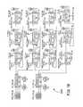
- FIGS. 1A-1Bare block diagrams of embodiments of a communication network 100 . Each of FIGS. 1A-1B shows a different embodiment of a communication network 100 . The various embodiments are labeled communications network 100 A through communications network 100 B. It is understood that aspects of these embodiments can be combined together to create additional embodiments sharing features from any combination of the embodiments.
- FIG. 1Ais block diagram of one exemplary embodiment of a communications network 100 , labeled communications network 100 A.
- the communications network 100 Arepresents a point-to-multipoint communications network that comprises a base station 101 , a host node 102 responsive to the base station 101 , and remote nodes 104 - 1 to 104 -M in communication with the host node 102 .
- the host node 102comprises a host base station interface 103 and a host transport interface 105 responsive to a host node processor 106 .
- Each of the remote nodes 104(such as remote nodes 104 - 1 to 104 -M) comprises a remote transport interface 107 (such as remote transport interface 107 - 1 to 107 -M) and an RF to digital interface 109 (such as RF to digital interface 109 - 1 to 109 -M), both responsive to a remote node processor 108 (such as remote node processor 108 - 1 to 108 -M).
- Each of the RF to digital interfaces 109(such as RF to digital interface 109 - 1 to 109 -M) is further responsive to an antenna port 110 (such as antenna port 110 - 1 to 110 -M).
- each host node processor 106 and remote node processor 108is configured to execute software or firmware (not shown) that causes the host node processor 106 and/or the remote node processor 108 to carry out various functions described herein.
- the softwarecomprises program instructions that are stored (or otherwise embodied) on an appropriate non-transitory storage medium or media (not show) such as flash or other non-volatile memory, magnetic disc drives, and/or optical dist drives. At least a portion of the program instructions are read from the storage medium by host node processor 106 and/or remote node processor 108 for execution thereby.
- the storage medium on or in which the program instructions are embodiedis also referred to here as a “program product”.
- the storage mediumis local to each host node processor 106 and/or remote node processor 108 .
- the storage mediumis a remote storage medium (for example, storage media that is accessible over a network or communication link) and/or a removable media.
- each host node processor 106 and/or remote node processor 108also includes suitable memory (not shown) that is coupled to host node processor 106 and/or remote node processor 108 for storing program instructions and data.
- each host base station interface 103 and each RF to digital interface 109is implemented with a Digital/Analog Radio Transceiver (DART board) commercially available from ADC Telecommunications, Inc. of Eden Prairie, Minn. as part of the FlexWaveTM Prism line of products.
- DART boardDigital/Analog Radio Transceiver
- the DART boardis also described in U.S. patent application Ser. No. 11/627,251, assigned to ADC Telecommunications, Inc., published in U.S. Patent Application Publication No. 2008/01101482, and incorporated herein by reference.
- each host base station interface 103 and each RF to digital interface 109is implemented with a plurality of DART boards, where one DART board is used for each port (such as D 1 , D 2 , D 3 ) at a host node 102 or a remote node 104 .
- different ratios of DART boards to portscan be used.
- some of the host base station interfaces 103do not convert between analog and digital and instead receive digital signals directly from the base station 101 .
- the digital signalsmay be reframed, converted to a different frequency, or manipulated in other ways at host base station interfaces 103 , even though there is no conversion from analog RF spectrum to digitized RF spectrum.
- each host transport interface 105 and each remote transport interface 107is implemented with a Serialized RF (SeRF board) commercially available from ADC Telecommunications, Inc. of Eden Prairie, MN as part of the FlexWaveTM Prism line of products.
- SeRF boardis also described in U.S. patent application Ser. No. 11/627,251, assigned to ADC Telecommunications, Inc., published in U.S. Patent Application Publication No. 2008/01101482, and incorporated herein by reference.
- each host transport interface 105 and each remote transport interface 107is implemented with a plurality of SeRF boards, where one SeRF board is used for each port (such as T 1 , T 2 , T 3 ) at a host node 102 or a remote node 104 .
- the host node processor 106 and each remote node processor 108are programmable processors, such as a microcontroller, an application-specific integrated circuit (ASIC), a field-programmable gate array (FPGA), a field-programmable object array (FPOA), or a programmable logic device (PLD).
- ASICapplication-specific integrated circuit
- FPGAfield-programmable gate array
- FPOAfield-programmable object array
- PLDprogrammable logic device
- the network 100 Ais capable of accommodating any appropriate number of remote nodes 104 as described above in communication network 100 A.
- communication network 100 Aincludes fewer remote nodes 104 than those shown in FIG. 1A .
- system 100 Aincludes more remote nodes 104 than those shown in FIG. 1A .
- the host node 102 and the remote nodes 104are communicatively coupled by a plurality of signal paths in a tree-and-branch network configuration representing a plurality of levels.
- the tree-and-branch network configurationfurther includes signal switches 112 and 113 .
- Each of the signal paths illustrated in FIG. 1Aare at least one of an electrical link, an optical fiber link, and a wireless transport link (such as millimeter wave, free space optics, or suitable combinations thereof), providing a medium-independent network architecture. It is understood that additional network configurations (such as a hub and spoke, a common bus, and the like) are also contemplated.
- the host base station interface 103 and each of the RF to digital interfaces 109include ports D 1 , D 2 , and D 3 .
- the ports D 1 , D 2 , and D 3are considered representative of a plurality of signal interference connections (such as RF, Ethernet, and the like) for the host base station interface 103 and each of the RF to digital interfaces 109 .
- the host base station interface 103converts between analog RF spectrum received from the base station 101 and digitized spectrum that is communicated with the remote nodes 104 . In other embodiments, the host base station interface 103 communicated digitized spectrum or signals with the base station 101 .
- the framing of the digitized spectrum or signalsmay need to be converted between the digitized spectrum or signals communicated with the base station 101 and the digitized spectrum communicated with the remote nodes 104 .
- the host transport interface 105 and each of the remote transport interfaces 107include ports T 1 , T 2 , and T 3 .
- the ports T 1 , T 2 , and T 3are considered representative of a plurality of transport interface connections for the host transport interface 105 .
- Each of the remote transport interfaces 107provide an appropriate signal conversion (such as a digital to serial or serial optical fiber) for each of the remote nodes 104 and the host node 102 of the communication network 100 A. It is understood that the ports D 1 to D 3 and T 1 to T 3 shown in FIG. 1 are not to be considered limiting the number of signal interface and transport ports contemplated by the system discussed here (e.g., the communication network 100 A is capable of accommodating any appropriate number of instances of signal interface and transport ports).
- Each remote node 104introduces one or more intrinsic processing delays.
- the remote transport interfaces 107includes a first intrinsic processing delay when passing signals between the transport interface connections T 1 and T 3 (commonly referred to as a “fiber-to-fiber” delay in this example).
- each of the RF to digital interfaces 109includes a second intrinsic processing delay for converting signals between digital and RF.
- the intrinsic processing delays in RF to digital interface 109are asymmetrical. This means that the intrinsic processing delay for upstream signals (signals going to the host node 102 ) and the intrinsic processing delay for downstream signals (signals coming from the host node 102 ) are different.
- the various intrinsic processing delaysare embedded in each of the remote node processors 108 (such as remote node processor 108 - 1 to 108 -M) for use in establishing the requested delay for the node.
- communication network 100 Aimplements an end-to-end pinging process to determine the signal path delay between each port (such as D 1 , D 2 , and D 3 ) in the RF to digital interface 109 at each remote node 104 and a corresponding host base station interface 103 at the host node 102 .
- each port in the RF to digital interface 109 at each remote node 104 in the communication network 100 Adiscovers its signal path delay back to a corresponding port in the host base station interface 103 of the host node 102 by sending a ping message to the host node 102 through the communication network 100 A.
- the corresponding port in the host base station interface 103 of the host node 102returns the ping message to the corresponding port of the RF to digital interface 109 of the pinging remote node 104 .
- the ping messageis sent along a path between the pinging remote node 104 and the host node 102 .
- a particular pinging remote node 104may be directly coupled with the host node 102 , such as with remote nodes 104 - 1 , 104 - 2 , and 104 - 3 .
- a particular pinging remote node 104may also have other remote nodes 104 intervening between itself and the host node 102 , such as with remote node 104 - 4 that has remote node 104 - 1 intervening; remote node 104 - 8 that has both remote node 104 - 4 and 104 - 1 intervening; remote node 104 - 5 that has remote node 104 - 2 intervening; remote node 104 - 9 that has both remote nodes 104 - 5 and 104 - 2 intervening; remote node 104 - 6 that has remote node 104 - 3 intervening; and remote node 104 - 10 that has both remote node 104 - 6 and 104 - 3 intervening.
- a particular pinging remote node 104may also have other components, or a combination of other components and other remote nodes, intervening between itself and the host node 102 , such as remote node 104 - 7 that has signal switches 112 and 113 and remote node 104 - 3 intervening; and remote node 104 -M that has remote node 104 - 7 , signal switches 112 and 113 , and remote node 104 - 3 intervening.
- any number of intervening remote nodes 104 or other componentsmay be intervening between a particular remote node 104 and the host node 102 .
- the signal path delay between a pinging port of the RF to digital interface 109 of a particular remote node 104is calculated based on the elapsed round-trip ping time between sending a ping message from the pinging port of the RF to digital interface 109 of the remote node 104 and receiving back a corresponding reply ping message from the corresponding port of the host base station interface 103 of the host node 102 .
- the signal path delay for a particular remote node 104is calculated to be this round-trip ping time.
- the signal path delay for a particular remote node 104is calculated to be a fraction of this round-trip ping time, such as one-half of the round-trip ping time.
- the signal path delay for a particular remote node 104is calculated from the round-trip ping time in other ways. While the precise method of calculation may vary from one embodiment to another, it is desirable that the method of calculation is consistent and defined for all remote nodes 104 in the communication network 100 A so that the signal path delay values for each remote node 104 can be properly used to adjust the delay associated with each remote node 104 in the communication network 100 A.
- each signal path delay between each pinging port of the RF to digital interface 109 of each remote node 104 and the corresponding port of the host base station interface 103 of the host node 102is calculated to represent the entire delay between the pinging port of the RF to digital interface 109 of the particular remote node 104 and the corresponding port of the host base station interface 103 of the host node 102 , including any transport delay, internal processing delay, and other intrinsic processing delay present between the pinging port of the RF to digital interface 109 of the pinging remote node 104 and the corresponding port of the host base station interface 103 of the host node 102 .
- each port of each RF to digital interface 109 of each remote node 104 and its corresponding port of the host base station interface 103 of the host node 102it is not necessary to factor in the internal processing delay (or other intrinsic delay) at each intervening remote node between a particular pinging remote node 104 and the host node 102 .
- the end-to-end pingis computationally less intensive than other methods requiring computation and aggregation of the delays associated with each hop between nodes in the network.
- the current system and methodallow a reduction of resource usage and lower overhead at each node in the communication network 100 A.
- Some embodiments of the communication network 100 Aimplement simulcast, where at least one of the ports of the host base station interface 103 of the host node 102 corresponds to a plurality of ports of at least one RF to digital interface 109 .
- at least one of the ports of the host base station interface 103 of the host node 102corresponds to both a first port in a first RF to digital interface 109 in a first remote node 104 (such as RF to digital interface 109 - 1 of remote node 104 - 1 ) and a second port in a second RF to digital interface 109 in a second remote node 104 (such as RF to digital interface 109 - 2 of remote node 104 - 2 or any of the other RF to digital interfaces 109 of any of the other remote nodes 104 ).
- one port of the host base station interface 103 of the host node 102communicates identical digitized spectrum in the forward link with a plurality of ports at a plurality of RF to digital interfaces 109 at a plurality of remote nodes 104 .
- the plurality of ports at the plurality of RF to digital interfaces 109 at a plurality of remote nodes 104communicate digitized spectrum in the reverse path that is aggregated and received at the single port of the host base station interface 103 of the host node 102 .
- the reverse path signalis aggregated through a series of summations. The actual method of aggregation of the simulcast may be done in various ways while still utilizing the methods and systems of end-to-end determination of delay described herein.
- the host nodemay have some internal processing delay associated with its host base station interface 103 (or any other internal processing delay not accounted for by the round-trip ping time) that can be used with the round-trip ping time and any other intrinsic delays that are not accounted for by the round-trip ping time to determine the signal path delay.
- the particular pinging remote nodemay have some internal processing delay associated with its RF to digital interface 109 or the respective antenna port 110 (or any other internal processing delay not accounted for by the round-trip ping time) that can be used with the round-trip ping time and any other intrinsic delays that are not accounted for by the round-trip ping time to determine the signal path delay.
- the remote nodes 104use the signal path delay calculated through this process to control the overall delay selected for each RF to digital interface 109 of each remote node 104 .
- a total delay for each RF to digital interface 109 of each remote nodemay be established during network installation.
- Each RF to digital interface 109 of each remote nodesets the amount of delay that it introduces into signals based on the signal path delay learned using the above-described process.
- a common time baseis established for RF to digital interfaces 109 in the remote nodes 104 in communication network 100 A.
- the ping messagesmay be used to verify integrity of the round-trip path. Both ping messages sent from RF to digital interfaces 109 of remote nodes 104 and reply ping messages sent from host base station interfaces 103 of host nodes 102 may be protected and validated by a cyclic redundancy check (CRC). In some embodiments, messages received at either host base station interfaces 103 of the host node 102 or RF to digital interfaces 109 of remote nodes 104 with invalid CRCs are ignored.
- CRCcyclic redundancy check
- a ping message received at a host digital interface 109 of a host node 102is identified as having an invalid CRC
- the host base station interface 103 of the host node 102will not send a reply ping message in response.
- a ping message received at a RF to digital interface 109 of a remote node 104is identified as having an invalid CRC
- the RF to digital interface 109 of the remote node 104ignores the invalid message.
- a first reverse path ping message initiated by a RF to digital interface 109 of one of the remote nodes 104might collide with a second reverse path ping message initiated by another RF to digital interface 109 of another one of the remote nodes 104 (such as RF to digital interface 109 - 2 of remote node 104 - 2 ).
- a collision between two ping messagesmay cause both messages to be corrupted so that neither ping message is received intact at a host base station interface 103 of a host node 102 (such as host base station interface 103 - 1 of host node 102 - 1 ).
- the corrupted message received at the host base station interface 103 of the host node 102may include bits from both the first and second reverse path ping messages. Such a corrupted message will be identified as invalid by the CRC performed by the host base station interface 103 of host node 102 and will not be replied to by the host base station interface 103 of host node 102 .
- an embodiment of communication network 100 Amay include configuration of each RF to digital interface 109 at each remote node 104 to detect whether or not it has received a valid ping reply message from the replying host digital interface 103 of the replying host node 104 in response to its initial ping message within a predefined amount of time. If a ping reply message is received at the pinging RF to digital interface 109 of the pinging remote node 104 before expiration of a predefined response and the ping message both: (1) has a valid CRC; and (2) corresponds to the pinging RF to digital interface 109 of the pinging remote node 104 , then the round-trip delay and signal path delay are calculated.
- the ping messageis resent when the next ping trigger occurs.
- Ping triggersoccur at pseudo-random time intervals.
- the ping trigger intervalmay be determined at each pinging remote node based on a pseudo-random back-off algorithm to minimize the chance of a collision between other upstream messages.
- some embodiments of communication network 100 Amay further calculate how many times a particular ping message has been sent from a pinging RF to digital interface of a pinging remote node 104 without a valid corresponding reply ping message having been received.
- a path integrity alarmmay be reported at the particular pinging remote node 104 in the communication network 100 A indicating that something is wrong with the data path between the pinging RF to digital interface 109 of the pinging remote node 104 and the corresponding host base station interface 103 of the corresponding host node 102 .
- This path integrity alarmmay alert a technician to a potential data path error so that the technician can investigate and correct the issue.
- the number of messages that must fail before the remote node reports a path integrity alarmmay be predetermined when the communication network 100 A is deployed, but may also be adjusted later. In other embodiments, a timeout period is used instead of a ping trigger.
- the ping messagesmay also be used to mute and un-mute the transmission and reception from an antenna coupled to a port of an RF to digital interface 109 on a remote node 104 .
- a certain number of valid ping messagesneed to be received back at a pinging RF to digital interface 109 of a remote node 104 before the pinging RF to digital interface un-mutes a port coupled to the associated antenna port 110 , allowing transmission and reception of a particular band through the data path between the port of the RF to digital interface 109 (such as port Dl of RF to digital interface 109 - 4 of remote node 104 - 4 ) and a host base station interface 103 (such as port D 1 of host base station interface 103 of host node 104 ) coupled to a service provider interface of base station 101 (such as service provider interface 1 of base station 101 - 1 ).
- This featuresensures the integrity of the path and compatibility between the pinging RF to digital interface 109 and the host base station interface 103 before un-muting the communications.
- FIG. 1Bis block diagram of another exemplary embodiment of a communications network 100 , labeled communications network 100 B.
- the communications network 100 Brepresents a multipoint-to-multipoint communications network that shares many components with communications network 100 A shown in FIG. 1A and described above.
- the primary distinction between communications network 100 B and communication network 100 Ais that communication network 100 B includes two or more host nodes 102 (such as host node 102 - 1 and host node 102 - 2 ) coupled with two or more base stations 101 (such as base station 101 - 1 and base station 101 - 2 ).
- a single remote node 104can be coupled to a plurality of host nodes 102 (such as remote node 104 - 2 which is connected to both host node 102 - 1 and host node 102 - 2 ).
- a single remote unitmay have two RF to digital interfaces 109 , where one is associated with a host base station interface 103 in one host node 102 (such as host base station interface 103 - 1 of host node 102 - 1 ) and the other is associated with a different host base station interface 103 in another host node 102 (such as host base station interface 103 - 2 in host node 102 - 2 ).
- one port of a RF to digital interface 109 of a remote nodemay be associated with one port of one host base station interface 103 in a host node 102 (such as D 1 of host base station interface 103 - 1 of host node 102 - 1 ).
- ping messagesare sent for each of the RF to digital interfaces 109 to a host node 102 having a host digital interface 109 associated with the respective RF to digital interface 109 .
- one port of RF to digital interface 109 of the remote unit 104may be associated with a host base station interface 103 of one host node 102 (such as host base station interface 103 - 1 of host node 102 - 1 ) while another port of RF to digital interface 109 of the remote node 104 (such as D 2 of RF to digital interface 109 - 1 of the remote node 104 - 4 ) may be associated with a host base station interface 103 of another host node 102 (such as host base station interface 103 - 2 of host node 102 - 2 ).
- communications network 100 Bincludes analog remote nodes 114 (such as analog remote nodes 114 - 1 and 114 -M coupled to remote node 104 - 11 ).
- analog remote nodes 114such as analog remote nodes 114 - 1 and 114 -M coupled to remote node 104 - 11 .
- intermediate frequenciesmay be used to transmit multiple bands across a single analog medium.
- a remote node 104(such as remote node 104 - 11 ) includes an analog IF to digital interface 111 (such as analog IF to digital interface 111 - 1 ) that converts between digitized RF spectrum received from the associated host node 102 and an analog IF frequency sent across the analog medium to an analog remote node 114 (such as analog remote node 114 - 1 ).
- each analog remote node 114(such as analog remote node 114 - 1 through analog remote node 114 -M) includes an analog IF transport interface 113 (such as analog IF transport interface 113 - 1 through analog IF transport interface 113 -M) and an IF to RF interface 116 (such as IF to RF interface 116 - 1 through IF to RF interface 116 -M) responsive to an analog remote node processor 118 (such as analog remote node processor 118 - 1 through analog remote node processor 118 -M).
- Each of the IF to RF interfaces 116(such as IF to RF interface 116 - 1 to 116 -M) is further responsive to an antenna port 110 (such as antenna port 110 - 12 to 110 -M).
- a plurality of analog remote nodescan be daisy chained off from a remote node in the communications network 100 B.
- other network topologiescan be used in both the digital and analog portions of the communications network 100 B.
- the end-to-end pingis only calculated in the digital portions of the network 100 B.
- an analog IF to digital interface 111 of a remote node 104calculates an end-to-end ping to a host base station interface 103 of a host node 102 (such as host base station interface 103 - 1 of a host node 102 - 1 ) using the methods described herein.
- the remote node 104 - 11can then add in some intrinsic delay to account for the delay through the various portions of the analog system (such as to IF to RF interface 116 - 1 of analog remote node 114 - 1 and IF to RF interface 116 -M of analog remote node 114 -M). In this way, the end-to-end delay between the analog nodes can also be estimated.
- the additional delay in the analog portion of the communications network 100 Bis disregarded because it is insubstantial compared to the delay introduced by the digital portion of the communication network 100 B. This may be the case because the distances between the remote nodes 104 and the host nodes 102 in the digital domain is much greater than the distances between the analog remote nodes 114 and the remote nodes 104 they are connected to (such as remote node 104 - 11 ).
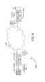
- FIG. 1Cis a block diagram of another exemplary embodiment of a communications network 100 , labeled communications network 100 C.
- the communications network 100 Crepresents a communications network that includes the host node 102 - 1 and the remote node 104 - 1 .
- Each of host node 102 - 1 and remote node 104 - 1include the components describe above.
- additional remote nodes 104 or other componentslie between host node 102 - 1 and remote node 104 - 1 in optional intervening component section 120 .
- optional intervening component section 120includes intervening remote nodes 104 , signal switches, and physical links, such as optical fibers, coaxial cables, and wireless links.
- the communications network 100 Cimplements an end-to-end ping as described herein.
- the precise contents of the optional intervening component section 120is not particularly relevant to the end-to-end ping as long as the components in the optional intervening component section 120 properly forward any ping initiation messages and ping reply messages between the host node 102 - 1 and remote node 104 - 1 .
- FIG. 2is a block diagram of a framework 200 for network applications.
- the framework 200comprises multiple layers, discussed below, that provide hardware-related service to enable each node of the communication network 100 A to function as shown above with respect to FIG. 1 (e.g., the host node 102 discovers the plurality of remote nodes 104 over the communication network 100 A).
- the framework 200comprises an application layer 202 , a network layer 204 , a data link layer 206 , and a physical layer 208 .
- Each layer of the framework 200compartmentalizes key functions required for any node of the communication network 100 to communicate with any other node of the communication network 100 .
- the physical layer 208is communicatively coupled to, and provides low level support for the data link layer 206 , the network layer 204 , and the application layer 202 .
- the physical layer 208resides on at least one of an optical fiber network, a coaxial cable network, and a wireless network.
- the physical layer 208provides electronic hardware support for sending and receiving data in a plurality of operations from the at least one network application hosted by the host node 102 .
- the data link layer 206provides error handling for the physical layer 208 , along with flow control and frame synchronization.
- the data link layer 206further includes a data frame sub-layer 210 .
- the data frame sub-layer 210comprises a plurality of data frames transferred on the physical layer 208 .
- the network layer 204is responsive to at least one programmable processor within the network 100 (for example, the host node processor 106 or at least one of the remote node processors 108 ).
- the network layer 204provides switching and routing capabilities within the network 100 for transmitting data between the nodes within the network 100 .
- the application layer 202is responsive to at least one of a simple network management protocol (SNMP), a common management information protocol (CMIP), a remote monitoring (RM) protocol, and any network communications protocol standard suitable for remote monitoring and network management.
- SNMPsimple network management protocol
- CMIPcommon management information protocol
- RMremote monitoring
- FIG. 3is a block diagram of an embodiment of the data frame sub-layer 210 of FIG. 2 , represented generally by the sub-layer 300 .
- the sub-layer 300comprises at least one data frame 302 (or optical fiber frame).
- Each data frame 302is composed of a plurality of slots organized into rows and columns as shown in FIG. 3 .
- Each RF to digital interface 109 of each remote node 104is assigned at least one timeslot in the reverse path to transmit digitized RF spectrum to a host base station interface 103 of a host node 102 .
- each RF to digital interface 109 of each remote node 104is assigned at least one timeslot in the forward path to receive digitized RF spectrum from a host base station interface 103 of a host node 102 .
- a single RF to digital interface 109is assigned multiple slots in the upstream and/or the downstream.
- a single host base station interface 103is assigned multiple slots in the upstream and/or downstream.
- implementing simulcast in the forward patha single host base station interface 103 of a host node 102 may transmit digitized RF spectrum in the downstream on at least one timeslot that is received at a plurality of RF to digital interfaces 109 at a plurality of remote nodes 104 .
- a plurality of RF to digital interfaces 109 at a plurality of remote nodes 104may transmit digitized RF spectrum in the upstream on the same timeslot, where the digitized RF spectrum is summed together or aggregated in some other way.
- Each timeslotsuch as example timeslot 304
- both the I sample 306 and the Q sample 308include 16 bits.
- the 16th bit of the I sample, bit 310is used to transmit the ping messages.
- a single bit 310is used in each timeslot of the data frame 302 to transmit the ping messages.
- a ping messagecan span multiple slots in a frame and can also span across frames. In the embodiments shown in FIG. 3 , where only one bit per timeslot is used to transmit the ping message, it may take multiple frames to transmit a single ping message.
- the ping messagecontains approximately 80 bits, requiring 80 slots for transmission.
- an RF to digital interface 109is assigned one timeslot per row of the data frame 302 , it would take five frames to transmit the 80 bits of one ping message.
- an RF to digital interface 109is assigned two timeslots per row of the data frame 302 , it would take two and a half frames to transmit the 80 bits of one ping message.
- the combined bits representing the ping message spanning multiple framesare sometimes referred to as a ping message superframe.
- An example embodiment of a ping message having 80 bitsmay include a number of elements.
- a frame headermay require 8 bits.
- the frame headeris used to frame the message and identify the message type.
- Example message typesinclude (1) messages initiated from a remote RF to digital interface 109 and directed toward an analog host base station interface 103 , (2) messages initiated from a remote RF to digital interface 109 and directed toward a digital host base station interface 103 , (3) messages initiated from an analog host base station interface 103 and directed toward a remote RF to digital interface 109 , and (4) messages initiated from a digital host base station interface 103 and directed toward a remote RF to digital interface 109 .
- the digital host base station interface 103is discussed above as being used when the base station outputs a digital signal to the host node 102 instead of an RF signal.
- a time slot countmay require 4 bits.
- the timeslot countis used to identify the number of timeslots the sending DART is programmed to. This timeslot count should agree between the RF to digital interface 109 and the corresponding host base station interface 103 and can be used to verify that the network is correctly configured and/or the integrity of the path the ping message is being sent on.
- a host base station interface IDmay require 8 bits.
- the host base station interface IDis a unique identifier code for the host base station interface 103 that may be inserted into the ping reply message by the host base station interface 103 .
- the RF to digital interface 109 at the pinging remote node 104can then verify that it is compatible with the type of the host base station interface 103 based on the host base station interface ID received back in the ping reply message.
- the RF to digital interface 109 at the pinging remote node 104is not compatible with the type of host base station interface 103 identified in the host base station interface ID, the RF to digital interface 109 can be muted and an alarm can be triggered to indicate a mismatch between the types of the pinging RF to digital interface 109 the host base station interface 103 .
- a unique path codemay require 37 bits.
- the unique path codeis a unique value that identifies the path between the RF to digital interface 109 and the host base station interface 103 . This unique value serves as a unique identifier for each RF to digital interface 109 in the system 100 .
- the system 100can have up to 8 levels of cascades between the host node and a RF to digital interface 109 .
- path codes of different lengthscan also be used, enabling various sizes of networks and levels of cascades.
- this unique path codeis supplied to the RF to digital interface 109 by the remote transport interface 107 of the remote node 104 .
- the unique path codeincludes a 4-bit host node ID number that identifies the host node 102 that contains the corresponding host base station interface 103 . In embodiments having a 4 bit host node ID number, there are only 16 options for host node ID numbers. If the host base station interface 103 receives a ping message that has a host node ID number that does not match its own, then the message is ignored.
- the unique path codealso includes a 3-bit host base station interface ID number that identifies the target host base station interface 103 within the host node 102 .
- the base station interface ID numberalso identifies a particular port within the host base station interface 103 of the host node 102 .
- the base station interface ID numberidentifies a communication port, such as a low-voltage differential signaling (LVDS) port, of the target host base station interface 103 within the host node 102 .
- LVDSlow-voltage differential signaling
- the unique path codealso includes a 27 bit fiber path ID that identifies the path between the host node 102 and the remote node 104 .
- This unique path codemay be broken into nine 3-bit values. The first 3-bit value represents the number of levels minus one in the cascaded mesh. For example, a system that only contains a host and a remote would have “000” in this field. The next eight 3-bit values represent the fiber port number of each link in the cascade. In systems with fewer than eight levels, the corresponding 3-bits will be unused and set to “000”.
- the unique path codealso includes a 3-bit RF to digital interface ID number that identifies the pinging RF to digital interface 109 within the remote node 104 .
- the base station interface ID numberalso identifies a particular port within the RF to digital interface 109 of the pinging remote node 104 .
- the RF to digital interface ID numberidentifies a low-voltage differential signaling (LVDS) port of the pinging RF to digital interface 109 within the pinging remote node 104 .
- LVDSlow-voltage differential signaling
- a cyclic redundancy check (CRC) codemay require 15-bits.
- the CRC codemay be used to verify the integrity of the ping message. If the CRC fails at the host node 102 , no ping reply message will be sent or any returned ping reply message will be incomplete.
- miscellaneous control status codemay require 8-bits. This miscellaneous control status code could be used for other features and functions in the system.
- a ping messageis sent in the reverse path from each RF to digital interface 109 on each remote node 104 to a host base station interface 103 of a host node 104 .
- the host base station interface 103 of the host node 104validates each ping message received. This validation may include validation of the message type, the host base station interface type, the host node ID number, the host base station ID number, and the CRC code. In some embodiments, a mismatch between any of these validated items and expected values causes the host base station interface 103 to ignore the ping message.
- the host base station interface 103could trigger an alarm if certain items are not validated.
- the host node 104replies to the pinging remote node 104 with a similar reply ping message in the forward direction.
- Both ping messages sent in the reverse path from the remote nodes 104 to the host node 102 and the reply ping messages sent in the forward path from the host node 102 to the pinging remote nodes 104include a unique identifier that identifies the particular RF to digital interface 109 uniquely from all the other RF to digital interfaces 109 .
- the reply ping messageis identical to the ping message.
- the host base station interface 103edits or adds to the received ping message in its reply ping message. The replying host base station interface 103 of the host node 102 sends the reply ping message back toward the pinging RF to digital interface 109 of the pinging remote node 104 .
- the pinging RF to digital interface 109 of the pinging remote node 104identifies that a reply ping message corresponding to its ping message has been received back by comparing the returned unique identifier with its unique identifiers. If the returned unique identifier matches a particular RF to digital interface 109 at one of the remote nodes 104 , the pinging RF to digital interface 109 of the pinging remote node 104 calculates total round-trip delay time between the initial transmission of the ping message and the receipt of the corresponding return ping message.
- While the RF to digital interfaces 109 of the remote nodes 104are described as performing the ping message transmission, reply ping message receipt, reply ping message validation, and round-trip delay calculation, in other embodiments, some or all of these actions are offloaded to the remote node processors 108 or other components of the remote node 104 .
- the host base station interfaces 103 of the host nodes 102are described as performing the ping message receipt, ping message validation, reply ping message transmission, and alarm generation, in other embodiments, some or all of these actions are offloaded to the host node processors 106 .
- FIG. 4shows an exemplary embodiment of a method flow diagram for a method 400 for calculating delay in a distributed antenna system.
- the method 400begins at block 402 , with calculating a delay in a distributed antenna system at a remote node.
- block 402is implemented using any of methods 500 A-B described below.
- the method 400proceeds to block 404 , with aiding the remote node in calculating delay in a distributed antenna system at a host node.
- block 404is implemented using sub-method 600 described below. It is understood that the various methods 500 A-B and 600 can be combined in various ways while still being within the scope of the claims below.
- FIG. 5Ashows an exemplary embodiment of a method flow diagram for a sub-method 500 A for calculating delay in a distributed antenna system at a remote node.
- the sub-method 500 Abegins at block 502 , where the sub-method 500 A waits for the next ping trigger to occur.
- Ping triggerscause the method to advance. It is desirable that the ping triggers occurring at various remote nodes in a distributed antenna system are staggered so that there is less likely a collision between the ping initiation messages and ping reply messages. Thus, in some embodiments, the ping triggers occur at pseudo-random intervals so that ping messages from each of the remote units are less likely to interfere with one another.
- block 502is optional and the sub-method 500 A does not wait for the next ping trigger 502 and instead immediately proceeds to block 504 .
- the sub-method 500 Aproceeds to block 504 , where a ping initiation message that uniquely identifies a first communication port of a remote node is sent from the remote node to a host node through a network.
- the first communication portis part of a RF to digital interface and an antenna is coupled to the first communication port.
- the first communication portis part of the transport interface that couples the remote node to the host node in the distributed antenna system.
- the sub-method 500 Aproceeds to block 506 , where it is determined whether a ping reply message is received before a predefined time period is elapsed since the ping initiation message was sent. Generally, this predetermined time period is selected to be long enough to allow a host node to receive and respond with a ping reply message to the remote unit. The predetermined time period is also selected to be short enough so that the ping message does not become stale. In some embodiments, block 506 is optional and the sub-method 500 A does not determine whether the ping reply message is received before a predefined time period has elapsed and instead immediately proceeds to block 508 .
- the sub-method 500 Abranches to block 508 , where it is determined whether the ping reply message uniquely identifies the first communication port of the remote node that was identified in the ping initiation message. In some embodiments, this determination is made by comparing a first unique identification sent from the remote node in the ping initiation message with a second unique identification received at the remote node in the ping reply message. If the first unique identification and the second unique identification match, then the ping reply message uniquely identifies the first communication port of the pinging remote node.
- the sub-method 500 Abranches to block 510 , where it is determined whether the ping reply message has been successfully received a predefined number of times. Successfully receipt occurs each time it is determined at block 508 that the ping message uniquely identifies the first communication port of the remote node.
- a counterkeeps track of how many successful receipts have occurred. In some embodiments, requiring a certain number of successful receipts before calculating the round-trip delay allows the sub-method 500 A to be used to validate the integrity of the data path on which the ping messages are being sent, which increases the likelihood that the round-trip delay is accurate.
- block 510may be used to un-mute the transmission and reception from an antenna coupled to a corresponding port of an RF to digital interface on the remote node, once the method is confident the integrity of the path is established. Until the integrity of the path is established by receiving the ping message successfully the predefined number of times, the transmission and reception from the antenna coupled to the corresponding RF to digital interface on the remote will be muted. In addition, the data path can be muted if it is determined that there is no data path integrity, such as at block 516 .
- the sub-method 500 Abranches to block 512 , where the round-trip delay between last sending the ping initiation message and receiving the ping reply message at the remote node is calculated at the remote node.
- this round-trip delayis used with round-trip delays associated with other remotes in a distributed antenna system to synchronize the delays between the various remotes in the distributed antenna system.
- the sub-method 500 Anext proceeds to block 514 where the attempt count and message received count are reset and the method returns to block 502 , where the sub-method 500 A waits for the next ping trigger to occur and the method repeats. The method is continually repeated to keep the round-trip delays continually updated.
- the sub-method 500 Abranches to block 516 , where it is determined whether a predefined number of unsuccessful attempts at sending the ping initiation message has been reached. If it is determined at block 516 that the predefined number of unsuccessful attempts at sending ping invitation messages has been reached, then the sub-method 500 A branches to block 518 , where an integrity alarm is reported.
- the integrity alarmindicates that there is something wrong with the integrity of the path between the pinging remote node and the host node. In some embodiments, the integrity alarm indicates which of test was failed, such as any of the tests in decision blocks 506 , 508 , and 510 .
- the sub-method 500 Acontinues onto block 514 and repeats according to the description above to see if a round-trip delay can still be determined. In other embodiments, once an integrity alarm is reported, the method will stop until the distributed antenna system is serviced to correct the integrity issue in the path.
- the sub-method 500 Abraches to block 516 , where it is determined whether a predefined number of unsuccessful attempts at sending the ping initiation message has been reached and continues as described above.
- the sub-method 500 Abranches to block 516 , where it is determined whether a predefined number of unsuccessful attempts at sending the ping initiation message has been reached and continues as described above. In other embodiments, if it is determined at block 510 that the ping reply message has not been successfully received a predefined number of times, then the sub-method 500 A branches directly back to block 502 without going first to block 516 .
- blocks 506 , 508 , and 510are in different orders, such that the various tests are performed in a different order.
- a signal path delay(as described above) is calculated at the remote node based on the round-trip delay.
- FIG. 5Bshows an exemplary embodiment of a method flow diagram for a sub-method 500 B for calculating delay in a distributed antenna system at a remote node.
- the sub-method 500 Bshares blocks 504 , 508 , and 512 with sub-method 500 A, but omits the other steps found in sub-method 500 A.
- the sub-method 500 Bbegins at block 504 , where a ping initiation message that uniquely identifies a first communication port of a remote node is sent from the remote node to a host node through a network.
- the first communication portis part of a RF to digital interface and an antenna is coupled to the first communication port.
- the sub-method 500 Bproceeds to block 508 , where it is determined whether the ping reply message uniquely identifies the first communication port of the remote node that was identified in the ping initiation message.
- the sub-method 500 Bcontinues to block 510 , where it is determined whether the ping reply message has been successfully received a predefined number of times. Successfully receipt occurs each time it is determined at block 508 that the ping message uniquely identifies the first communication port of the remote node. In some embodiments, a counter keeps track of how many successful receipts have occurred.
- the sub-method 500 Bbranches to optional block 520 , where the exception is handled.
- the optional block 520triggers errors or simply ignores the reply message that does not uniquely identify the first communication port of the remote node.
- sub-method 500 Bcould be repeated to send more ping initiation messages and receive more ping reply messages.
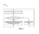
- FIG. 6shows an exemplary embodiment of a method flow diagram for a sub-method 600 for aiding a remote node in calculating delay in a distributed antenna system at a host node.
- the sub-method 600can be implemented in concert with sub-method 500 A described above to implement a method of performing a complete end-to-end ping.
- the sub-method 600begins at block 501 and proceeds to block 602 , where a ping initiation message is received at a host node.
- the remote nodeincludes a host base station interface and the host base station interface receives the ping initiation message.
- the ping initiation messageis a ping message sent from a remote unit in a network.
- the methodproceeds to block 604 , where the ping initiation message is validated.
- the ping initiation messagecan be validated in a number of ways, including but not limited to, validation of a CRC code, a message type, a host base station interface type, a host node ID number, and/or a host base station ID number. The validation of some of these values can occur by simply comparing the value received in the ping initiation message with an expected value stored in the host node 102 .
- this second ping initiation messageis from the same remote unit as the first ping initiation message. In other embodiments, this second ping initiation message is from a different remote unit as the second ping initiation message.
- the sub-method 600branches to block 608 , where the ping initiation message is ignored. In other embodiments, an alarm can be triggered by the lack of validation of the message. The triggered alarm may include an indication of how the ping initiation message failed validation. In other embodiments, there is no block 608 .
- the sub-method 600next continues back to block 602 , where another ping initiation message is received and the sub-method 600 is repeated. In some embodiments, this second ping initiation message is from the same remote unit as the first ping initiation message. In other embodiments, this second ping initiation message is from a different remote unit as the second ping initiation message.
- each of the sub-methods described abovesuch as sub-method 500 A, sub-method 500 B, and sub-method 600 , are implemented as individual methods.
Landscapes
- Engineering & Computer Science (AREA)
- Computer Networks & Wireless Communication (AREA)
- Signal Processing (AREA)
- Health & Medical Sciences (AREA)
- Cardiology (AREA)
- General Health & Medical Sciences (AREA)
- Environmental & Geological Engineering (AREA)
- Multimedia (AREA)
- Mobile Radio Communication Systems (AREA)
Abstract
Description
Claims (44)
Priority Applications (2)
| Application Number | Priority Date | Filing Date | Title |
|---|---|---|---|
| US15/173,203USRE47545E1 (en) | 2011-06-21 | 2016-06-03 | End-to-end delay management for distributed communications networks |
| US16/525,277USRE49070E1 (en) | 2011-06-21 | 2019-07-29 | End-to-end delay management for distributed communications networks |
Applications Claiming Priority (2)
| Application Number | Priority Date | Filing Date | Title |
|---|---|---|---|
| US13/165,294US8743718B2 (en) | 2011-06-21 | 2011-06-21 | End-to-end delay management for distributed communications networks |
| US15/173,203USRE47545E1 (en) | 2011-06-21 | 2016-06-03 | End-to-end delay management for distributed communications networks |
Related Parent Applications (1)
| Application Number | Title | Priority Date | Filing Date |
|---|---|---|---|
| US13/165,294ReissueUS8743718B2 (en) | 2011-06-21 | 2011-06-21 | End-to-end delay management for distributed communications networks |
Related Child Applications (1)
| Application Number | Title | Priority Date | Filing Date |
|---|---|---|---|
| US13/165,294ContinuationUS8743718B2 (en) | 2011-06-21 | 2011-06-21 | End-to-end delay management for distributed communications networks |
Publications (1)
| Publication Number | Publication Date |
|---|---|
| USRE47545E1true USRE47545E1 (en) | 2019-07-30 |
Family
ID=47361766
Family Applications (3)
| Application Number | Title | Priority Date | Filing Date |
|---|---|---|---|
| US13/165,294CeasedUS8743718B2 (en) | 2011-06-21 | 2011-06-21 | End-to-end delay management for distributed communications networks |
| US15/173,203Active2032-01-07USRE47545E1 (en) | 2011-06-21 | 2016-06-03 | End-to-end delay management for distributed communications networks |
| US16/525,277Active2032-01-07USRE49070E1 (en) | 2011-06-21 | 2019-07-29 | End-to-end delay management for distributed communications networks |
Family Applications Before (1)
| Application Number | Title | Priority Date | Filing Date |
|---|---|---|---|
| US13/165,294CeasedUS8743718B2 (en) | 2011-06-21 | 2011-06-21 | End-to-end delay management for distributed communications networks |
Family Applications After (1)
| Application Number | Title | Priority Date | Filing Date |
|---|---|---|---|
| US16/525,277Active2032-01-07USRE49070E1 (en) | 2011-06-21 | 2019-07-29 | End-to-end delay management for distributed communications networks |
Country Status (6)
| Country | Link |
|---|---|
| US (3) | US8743718B2 (en) |
| EP (1) | EP2724504A4 (en) |
| KR (1) | KR101548122B1 (en) |
| CN (1) | CN103748851B (en) |
| CA (1) | CA2838729A1 (en) |
| WO (1) | WO2012177459A2 (en) |
Cited By (6)
| Publication number | Priority date | Publication date | Assignee | Title |
|---|---|---|---|---|
| USRE49070E1 (en) | 2011-06-21 | 2022-05-10 | Commscope Technologies Llc | End-to-end delay management for distributed communications networks |
| US11445455B2 (en) | 2013-02-07 | 2022-09-13 | Commscope Technologies Llc | Radio access networks |
| US11601951B2 (en) | 2013-02-07 | 2023-03-07 | Commscope Technologies Llc | Radio access networks |
| US11706640B2 (en) | 2013-02-07 | 2023-07-18 | Commscope Technologies Llc | Radio access networks |
| US11974269B2 (en) | 2014-06-09 | 2024-04-30 | Commscope Technologies Llc | Radio access networks |
| US12219510B2 (en) | 2018-08-29 | 2025-02-04 | Commscope Technologies Llc | Clock synchronization in a centralized radio access network having multiple controllers |
Families Citing this family (66)
| Publication number | Priority date | Publication date | Assignee | Title |
|---|---|---|---|---|
| CN102369678B (en) | 2009-02-03 | 2015-08-19 | 康宁光缆系统有限责任公司 | Optical fiber based distributed antenna systems, assemblies and related methods for calibrating optical fiber based distributed antenna systems, assemblies |
| US9673904B2 (en) | 2009-02-03 | 2017-06-06 | Corning Optical Communications LLC | Optical fiber-based distributed antenna systems, components, and related methods for calibration thereof |
| CN102396171B (en) | 2009-02-03 | 2015-09-30 | 康宁光缆系统有限责任公司 | Based on the distributing antenna system of optical fiber, assembly and the correlation technique for monitoring and configure distributing antenna system based on optical fiber, assembly |
| US8280259B2 (en) | 2009-11-13 | 2012-10-02 | Corning Cable Systems Llc | Radio-over-fiber (RoF) system for protocol-independent wired and/or wireless communication |
| US8275265B2 (en) | 2010-02-15 | 2012-09-25 | Corning Cable Systems Llc | Dynamic cell bonding (DCB) for radio-over-fiber (RoF)-based networks and communication systems and related methods |
| US9525488B2 (en) | 2010-05-02 | 2016-12-20 | Corning Optical Communications LLC | Digital data services and/or power distribution in optical fiber-based distributed communications systems providing digital data and radio frequency (RF) communications services, and related components and methods |
| US20110268446A1 (en) | 2010-05-02 | 2011-11-03 | Cune William P | Providing digital data services in optical fiber-based distributed radio frequency (rf) communications systems, and related components and methods |
| WO2012024247A1 (en) | 2010-08-16 | 2012-02-23 | Corning Cable Systems Llc | Remote antenna clusters and related systems, components, and methods supporting digital data signal propagation between remote antenna units |
| US9252874B2 (en) | 2010-10-13 | 2016-02-02 | Ccs Technology, Inc | Power management for remote antenna units in distributed antenna systems |
| KR101874655B1 (en) | 2011-02-07 | 2018-07-04 | 달리 시스템즈 씨오. 엘티디. | Daisy-chained ring of remote units for a distributed antenna system |
| EP2678972B1 (en) | 2011-02-21 | 2018-09-05 | Corning Optical Communications LLC | Providing digital data services as electrical signals and radio-frequency (rf) communications over optical fiber in distributed communications systems, and related components and methods |
| WO2012148940A1 (en) | 2011-04-29 | 2012-11-01 | Corning Cable Systems Llc | Systems, methods, and devices for increasing radio frequency (rf) power in distributed antenna systems |
| WO2012148938A1 (en) | 2011-04-29 | 2012-11-01 | Corning Cable Systems Llc | Determining propagation delay of communications in distributed antenna systems, and related components, systems and methods |
| AU2012302074B2 (en) | 2011-08-29 | 2017-02-16 | Commscope Technologies Llc | Configuring a distributed antenna system |
| US11564110B2 (en) | 2011-11-07 | 2023-01-24 | Dali Wireless, Inc. | Soft hand-off and routing data in a virtualized distributed antenna system |
| WO2013162988A1 (en) | 2012-04-25 | 2013-10-31 | Corning Cable Systems Llc | Distributed antenna system architectures |
| US10506454B2 (en)* | 2012-07-31 | 2019-12-10 | Dali Systems Co., Ltd. | Optimization of traffic load in a distributed antenna system |
| WO2014024192A1 (en) | 2012-08-07 | 2014-02-13 | Corning Mobile Access Ltd. | Distribution of time-division multiplexed (tdm) management services in a distributed antenna system, and related components, systems, and methods |
| US9439242B2 (en) | 2012-08-13 | 2016-09-06 | Dali Systems Co., Ltd. | Time synchronized routing in a distributed antenna system |
| US9456383B2 (en) | 2012-08-27 | 2016-09-27 | Qualcomm Incorporated | Device and method for adaptive rate multimedia communications on a wireless network |
| US9247448B2 (en) | 2012-08-27 | 2016-01-26 | Qualcomm Incorporated | Device and method for adaptive rate multimedia communications on a wireless network |
| US9455784B2 (en) | 2012-10-31 | 2016-09-27 | Corning Optical Communications Wireless Ltd | Deployable wireless infrastructures and methods of deploying wireless infrastructures |
| US9647758B2 (en) | 2012-11-30 | 2017-05-09 | Corning Optical Communications Wireless Ltd | Cabling connectivity monitoring and verification |
| US10146732B2 (en)* | 2013-01-22 | 2018-12-04 | Apple Inc. | Time-division multiplexed data bus interface |
| US20140320340A1 (en)* | 2013-02-21 | 2014-10-30 | Dali Systems Co. Ltd. | Indoor localization using analog off-air access units |
| US20140301181A1 (en)* | 2013-04-03 | 2014-10-09 | Qualcomm Incorporated | Detecting, reporting, and recovering from potential service disruptions |
| WO2014199380A1 (en) | 2013-06-12 | 2014-12-18 | Corning Optical Communications Wireless, Ltd. | Time-division duplexing (tdd) in distributed communications systems, including distributed antenna systems (dass) |
| CN105452951B (en) | 2013-06-12 | 2018-10-19 | 康宁光电通信无线公司 | Voltage type optical directional coupler |
| US9247543B2 (en) | 2013-07-23 | 2016-01-26 | Corning Optical Communications Wireless Ltd | Monitoring non-supported wireless spectrum within coverage areas of distributed antenna systems (DASs) |
| US9661781B2 (en) | 2013-07-31 | 2017-05-23 | Corning Optical Communications Wireless Ltd | Remote units for distributed communication systems and related installation methods and apparatuses |
| US9385810B2 (en) | 2013-09-30 | 2016-07-05 | Corning Optical Communications Wireless Ltd | Connection mapping in distributed communication systems |
| KR101621400B1 (en)* | 2013-12-20 | 2016-05-16 | 주식회사 쏠리드 | An optical repeating system and a method of setting up identification information of a remote device therein |
| US20170250927A1 (en) | 2013-12-23 | 2017-08-31 | Dali Systems Co. Ltd. | Virtual radio access network using software-defined network of remotes and digital multiplexing switches |
| US9178635B2 (en) | 2014-01-03 | 2015-11-03 | Corning Optical Communications Wireless Ltd | Separation of communication signal sub-bands in distributed antenna systems (DASs) to reduce interference |
| US9775123B2 (en) | 2014-03-28 | 2017-09-26 | Corning Optical Communications Wireless Ltd. | Individualized gain control of uplink paths in remote units in a distributed antenna system (DAS) based on individual remote unit contribution to combined uplink power |
| US9357551B2 (en) | 2014-05-30 | 2016-05-31 | Corning Optical Communications Wireless Ltd | Systems and methods for simultaneous sampling of serial digital data streams from multiple analog-to-digital converters (ADCS), including in distributed antenna systems |
| AU2015274511B2 (en)* | 2014-06-11 | 2019-08-15 | Outdoor Wireless Networks LLC | Bitrate efficient transport through distributed antenna systems |
| US9730228B2 (en) | 2014-08-29 | 2017-08-08 | Corning Optical Communications Wireless Ltd | Individualized gain control of remote uplink band paths in a remote unit in a distributed antenna system (DAS), based on combined uplink power level in the remote unit |
| US9307506B1 (en)* | 2014-09-09 | 2016-04-05 | Sprint Communications Company L.P. | Implementation of a fiber distributed antenna system network while maintaining synchronization |
| US9602210B2 (en) | 2014-09-24 | 2017-03-21 | Corning Optical Communications Wireless Ltd | Flexible head-end chassis supporting automatic identification and interconnection of radio interface modules and optical interface modules in an optical fiber-based distributed antenna system (DAS) |
| US9420542B2 (en) | 2014-09-25 | 2016-08-16 | Corning Optical Communications Wireless Ltd | System-wide uplink band gain control in a distributed antenna system (DAS), based on per band gain control of remote uplink paths in remote units |
| US10659163B2 (en) | 2014-09-25 | 2020-05-19 | Corning Optical Communications LLC | Supporting analog remote antenna units (RAUs) in digital distributed antenna systems (DASs) using analog RAU digital adaptors |
| CN105893200A (en)* | 2014-10-21 | 2016-08-24 | 北京京航计算通讯研究所 | Method based on model replacement for inspecting equivalence of blackbox in FPGA |
| US9842013B2 (en)* | 2014-10-27 | 2017-12-12 | Aruba Networks, Inc. | Dynamic adaptive approach for failure detection of node in a cluster |
| WO2016071902A1 (en) | 2014-11-03 | 2016-05-12 | Corning Optical Communications Wireless Ltd. | Multi-band monopole planar antennas configured to facilitate improved radio frequency (rf) isolation in multiple-input multiple-output (mimo) antenna arrangement |
| US9860863B2 (en)* | 2014-11-06 | 2018-01-02 | Commscope Technologies Llc | Static delay compensation in a telecommunications system |
| WO2016075696A1 (en) | 2014-11-13 | 2016-05-19 | Corning Optical Communications Wireless Ltd. | Analog distributed antenna systems (dass) supporting distribution of digital communications signals interfaced from a digital signal source and analog radio frequency (rf) communications signals |
| WO2016098111A1 (en) | 2014-12-18 | 2016-06-23 | Corning Optical Communications Wireless Ltd. | Digital- analog interface modules (da!ms) for flexibly.distributing digital and/or analog communications signals in wide-area analog distributed antenna systems (dass) |
| WO2016098109A1 (en) | 2014-12-18 | 2016-06-23 | Corning Optical Communications Wireless Ltd. | Digital interface modules (dims) for flexibly distributing digital and/or analog communications signals in wide-area analog distributed antenna systems (dass) |
| KR101868964B1 (en) | 2014-12-30 | 2018-06-19 | 주식회사 쏠리드 | Node unit capable of measuring and compensation transmission delay and distributed antenna system including it |
| KR102153396B1 (en) | 2014-12-30 | 2020-09-08 | 주식회사 쏠리드 | Node unit capable of measuring delay and distributed antenna system including it |
| US20160249365A1 (en) | 2015-02-19 | 2016-08-25 | Corning Optical Communications Wireless Ltd. | Offsetting unwanted downlink interference signals in an uplink path in a distributed antenna system (das) |
| US9681313B2 (en) | 2015-04-15 | 2017-06-13 | Corning Optical Communications Wireless Ltd | Optimizing remote antenna unit performance using an alternative data channel |
| US9948349B2 (en) | 2015-07-17 | 2018-04-17 | Corning Optical Communications Wireless Ltd | IOT automation and data collection system |
| US10560214B2 (en) | 2015-09-28 | 2020-02-11 | Corning Optical Communications LLC | Downlink and uplink communication path switching in a time-division duplex (TDD) distributed antenna system (DAS) |
| US10236924B2 (en) | 2016-03-31 | 2019-03-19 | Corning Optical Communications Wireless Ltd | Reducing out-of-channel noise in a wireless distribution system (WDS) |
| KR102246968B1 (en)* | 2016-12-21 | 2021-04-30 | 주식회사 쏠리드 | Headend for distributed antenna system and operating method thereof |
| US10298328B2 (en)* | 2016-12-21 | 2019-05-21 | Solid, Inc. | Head-end device of distributed antenna system and method of operation thereof |
| US11277326B2 (en)* | 2020-03-31 | 2022-03-15 | Netflix, Inc. | Techniques for detecting changes to circuit delays in telecommunications networks |
| CN115038172A (en)* | 2021-03-03 | 2022-09-09 | 中国移动通信有限公司研究院 | A time slot allocation processing method, device and storage medium |
| US12047264B2 (en) | 2021-08-13 | 2024-07-23 | Itron, Inc. | Determining network reliability using message success rates |
| US11924077B2 (en) | 2021-08-13 | 2024-03-05 | Itron, Inc. | Determining network reliability using message success rates |
| US12068931B2 (en)* | 2021-08-13 | 2024-08-20 | Itron, Inc. | Determining network reliability using message success rates |
| US11483224B1 (en) | 2021-08-13 | 2022-10-25 | Itron, Inc. | Determining network reliability using message success rates |
| US11973855B2 (en)* | 2021-08-25 | 2024-04-30 | Siemens Canada Limited | PTP transparent clock with inter-VLAN forwarding |
| CN114614948A (en)* | 2022-03-16 | 2022-06-10 | 广州物联网研究院 | LoRa networking method and system |
Citations (53)
| Publication number | Priority date | Publication date | Assignee | Title |
|---|---|---|---|---|
| US4183054A (en) | 1977-09-30 | 1980-01-08 | Harris Corporation | Digital, frequency-translated, plural-channel, vestigial sideband television communication system |
| US4611323A (en) | 1983-05-24 | 1986-09-09 | Ant Nachrichtentechnik Gmbh | Method for transmitting digitally coded analog signals |
| US4628501A (en) | 1983-12-29 | 1986-12-09 | The United States Of America As Represented By The Secretary Of The Army | Optical communications systems |
| US4654843A (en) | 1982-09-17 | 1987-03-31 | U.S. Philips Corporation | Signal distribution system |
| US4691292A (en) | 1983-04-13 | 1987-09-01 | Rca Corporation | System for digital multiband filtering |
| EP0391597A2 (en) | 1989-04-04 | 1990-10-10 | AT&T Corp. | Optical fiber microcellular mobile radio |
| US4999831A (en) | 1989-10-19 | 1991-03-12 | United Telecommunications, Inc. | Synchronous quantized subcarrier multiplexer for digital transport of video, voice and data |
| WO1991015927A1 (en) | 1990-04-10 | 1991-10-17 | British Telecommunications Public Limited Company | Signal distribution |
| US5193109A (en) | 1989-02-06 | 1993-03-09 | Pactel Corporation | Zoned microcell with sector scanning for cellular telephone system |
| US5243598A (en) | 1991-04-02 | 1993-09-07 | Pactel Corporation | Microcell system in digital cellular |
| US5321849A (en) | 1991-05-22 | 1994-06-14 | Southwestern Bell Technology Resources, Inc. | System for controlling signal level at both ends of a transmission link based on a detected valve |
| US5339184A (en) | 1992-06-15 | 1994-08-16 | Gte Laboratories Incorporated | Fiber optic antenna remoting for multi-sector cell sites |
| KR950704866A (en) | 1993-08-27 | 1995-11-20 | 하비 피. 화이트 | DUAL DISTRIBUTIED ANTENNA SYSTEM |
| US5506847A (en) | 1993-04-26 | 1996-04-09 | Kabushiki Kaisha Toshiba | ATM-lan system using broadcast channel for transferring link setting and chaining requests |
| US5805983A (en) | 1996-07-18 | 1998-09-08 | Ericsson Inc. | System and method for equalizing the delay time for transmission paths in a distributed antenna network |
| US6205120B1 (en) | 1998-03-13 | 2001-03-20 | Packeteer, Inc. | Method for transparently determining and setting an optimal minimum required TCP window size |
| US6236365B1 (en) | 1996-09-09 | 2001-05-22 | Tracbeam, Llc | Location of a mobile station using a plurality of commercial wireless infrastructures |
| US6430160B1 (en) | 2000-02-29 | 2002-08-06 | Verizon Laboratories Inc. | Estimating data delays from poisson probe delays |
| KR20030001491A (en) | 2000-05-15 | 2003-01-06 | 노키아 코포레이션 | Method to calculate true round trip propagation delay and user equipment location in wcdma/utran |
| US6539026B1 (en) | 1999-03-15 | 2003-03-25 | Cisco Technology, Inc. | Apparatus and method for delay management in a data communications network |
| KR20030059259A (en) | 2000-11-21 | 2003-07-07 | 인터내셔널 비지네스 머신즈 코포레이션 | Costs in data networks |
| US6597678B1 (en)* | 1999-02-01 | 2003-07-22 | Hitachi, Ltd. | Radio communication system using adaptive array antenna |
| US20030185571A1 (en)* | 2002-01-15 | 2003-10-02 | Hyun-Pyo Lee | Method and apparatus for compensating for optical transmission delay in a synchronous mobile communication system using synchronous digital hierarchy |
| US6647210B1 (en) | 1999-04-16 | 2003-11-11 | Fujitsu Limited | Delay adjustment unit and method, optical network unit, and communication system |
| US6690892B1 (en) | 2000-11-20 | 2004-02-10 | Quantum Bridge, Communications, Inc. | Method and apparatus for controlling delay in a shared communications network |
| US6700893B1 (en) | 1999-11-15 | 2004-03-02 | Koninklijke Philips Electronics N.V. | System and method for controlling the delay budget of a decoder buffer in a streaming data receiver |
| US20040063454A1 (en) | 2002-10-01 | 2004-04-01 | Nec Corporation | End-to-end delay control method for both suppressing end-to-end delay time to a standard value or less and optimizing power-save operations |
| US20040165532A1 (en) | 2002-06-07 | 2004-08-26 | Poor Robert Dunbar | Ad hoc wireless network using gradient routing |
| US6791949B1 (en) | 2000-04-28 | 2004-09-14 | Raytheon Company | Network protocol for wireless ad hoc networks |
| US20050021737A1 (en) | 2003-05-01 | 2005-01-27 | Ellison Carl M. | Liveness protocol |
| US6977942B2 (en) | 1999-12-30 | 2005-12-20 | Nokia Corporation | Method and a device for timing the processing of data packets |
| US20060037069A1 (en)* | 2004-08-16 | 2006-02-16 | Fisher Gerald B | Systems and methods for communicating messages |
| US7035210B2 (en) | 2001-07-12 | 2006-04-25 | Telefonaktiebolaget Lm Ericsson (Publ) | Media stream delay monitoring for node |
| US7058050B2 (en) | 2000-12-01 | 2006-06-06 | Telefonaktiebolaget L M Ericsson (Publ) | Flexible inter-network communication scheduling |
| US7113536B2 (en) | 2001-04-16 | 2006-09-26 | Telefonaktiebolaget L M Ericsson (Publ) | Rendezvous point interpiconet scheduling |
| US7161926B2 (en) | 2001-07-03 | 2007-01-09 | Sensoria Corporation | Low-latency multi-hop ad hoc wireless network |
| US7184920B2 (en) | 2004-01-19 | 2007-02-27 | Fujitsu Limited | Delay measurement system |
| US20070064618A1 (en)* | 2005-09-16 | 2007-03-22 | Garcia Francisco J | Method of forming protocol data units, protocol data units and protocol data unit generation apparatus |
| US20080194226A1 (en)* | 2007-02-13 | 2008-08-14 | Antonio Rivas | Method and Apparatus for Providing Location Services for a Distributed Network |
| WO2009023689A2 (en) | 2007-08-15 | 2009-02-19 | Adc Telecommunications, Inc. | Delay management for distributed communications networks |
| US7546138B2 (en)* | 2002-12-03 | 2009-06-09 | Adc Telecommunications, Inc. | Communication system and method with gain control for signals from distributed antennas |
| US20100008250A1 (en)* | 2007-03-23 | 2010-01-14 | Fujitsu Limited | Method and apparatus for measuring packet transmission quality |
| KR20100060032A (en) | 2007-10-05 | 2010-06-04 | 콸콤 인코포레이티드 | Session initiation protocol registration with ping |
| US20100202356A1 (en) | 2009-02-12 | 2010-08-12 | Adc Telecommunications, Inc. | Backfire distributed antenna system (das) with delayed transport |
| US20100226296A1 (en)* | 2009-03-03 | 2010-09-09 | Adc Telecommunications, Inc. | Range extension for time division duplex systems |
| US20110039497A1 (en) | 2008-04-25 | 2011-02-17 | Telefonaktiebolaget Lm Ericsson (Publ) | Compensation for Propagation Delay in a Wireless Communication System |
| US7940685B1 (en)* | 2005-11-16 | 2011-05-10 | At&T Intellectual Property Ii, Lp | Method and apparatus for monitoring a network |
| US8224233B2 (en)* | 2009-10-09 | 2012-07-17 | At&T Mobility Ii Llc | Regulation of service in restricted telecommunication service area |
| US20120218911A1 (en)* | 2011-02-25 | 2012-08-30 | Fujitsu Limited | Transceiver Set Assignment Scheme For A Distributed Antenna System |
| US20120257516A1 (en)* | 2011-04-05 | 2012-10-11 | Cisco Technology, Inc. | Multi-Receiver Combining for Distributed Antenna Systems with Code Division Multiple Access Radio Frequency Uplink Sources |
| US20120327800A1 (en)* | 2011-06-24 | 2012-12-27 | Samsung Electronics Co., Ltd. | Method and apparatus for measuring downlink interference in ofdm mobile communication system |
| US8428550B2 (en)* | 2009-07-30 | 2013-04-23 | Extenet Systems Inc. | Real-time location determination for in-building distributed antenna systems |
| US8743718B2 (en) | 2011-06-21 | 2014-06-03 | Adc Telecommunications, Inc. | End-to-end delay management for distributed communications networks |
Family Cites Families (2)
| Publication number | Priority date | Publication date | Assignee | Title |
|---|---|---|---|---|
| DE69523113T2 (en) | 1994-03-07 | 2002-06-06 | Koninklijke Philips Electronics N.V., Eindhoven | NOISE MEASUREMENT |
| US8737454B2 (en) | 2007-01-25 | 2014-05-27 | Adc Telecommunications, Inc. | Modular wireless communications platform |
- 2011
- 2011-06-21USUS13/165,294patent/US8743718B2/ennot_activeCeased
- 2012
- 2012-06-13CACA2838729Apatent/CA2838729A1/ennot_activeAbandoned
- 2012-06-13EPEP12802489.0Apatent/EP2724504A4/ennot_activeCeased
- 2012-06-13WOPCT/US2012/042237patent/WO2012177459A2/enactiveApplication Filing
- 2012-06-13CNCN201280040774.6Apatent/CN103748851B/ennot_activeExpired - Fee Related
- 2012-06-13KRKR1020147000956Apatent/KR101548122B1/ennot_activeExpired - Fee Related
- 2016
- 2016-06-03USUS15/173,203patent/USRE47545E1/enactiveActive
- 2019
- 2019-07-29USUS16/525,277patent/USRE49070E1/enactiveActive
Patent Citations (60)
| Publication number | Priority date | Publication date | Assignee | Title |
|---|---|---|---|---|
| US4183054A (en) | 1977-09-30 | 1980-01-08 | Harris Corporation | Digital, frequency-translated, plural-channel, vestigial sideband television communication system |
| US4654843A (en) | 1982-09-17 | 1987-03-31 | U.S. Philips Corporation | Signal distribution system |
| US4691292A (en) | 1983-04-13 | 1987-09-01 | Rca Corporation | System for digital multiband filtering |
| US4611323A (en) | 1983-05-24 | 1986-09-09 | Ant Nachrichtentechnik Gmbh | Method for transmitting digitally coded analog signals |
| US4628501A (en) | 1983-12-29 | 1986-12-09 | The United States Of America As Represented By The Secretary Of The Army | Optical communications systems |
| US5193109A (en) | 1989-02-06 | 1993-03-09 | Pactel Corporation | Zoned microcell with sector scanning for cellular telephone system |
| EP0391597A2 (en) | 1989-04-04 | 1990-10-10 | AT&T Corp. | Optical fiber microcellular mobile radio |
| US4999831A (en) | 1989-10-19 | 1991-03-12 | United Telecommunications, Inc. | Synchronous quantized subcarrier multiplexer for digital transport of video, voice and data |
| WO1991015927A1 (en) | 1990-04-10 | 1991-10-17 | British Telecommunications Public Limited Company | Signal distribution |
| US5243598A (en) | 1991-04-02 | 1993-09-07 | Pactel Corporation | Microcell system in digital cellular |
| US5321849A (en) | 1991-05-22 | 1994-06-14 | Southwestern Bell Technology Resources, Inc. | System for controlling signal level at both ends of a transmission link based on a detected valve |
| US5339184A (en) | 1992-06-15 | 1994-08-16 | Gte Laboratories Incorporated | Fiber optic antenna remoting for multi-sector cell sites |
| US5506847A (en) | 1993-04-26 | 1996-04-09 | Kabushiki Kaisha Toshiba | ATM-lan system using broadcast channel for transferring link setting and chaining requests |
| KR950704866A (en) | 1993-08-27 | 1995-11-20 | 하비 피. 화이트 | DUAL DISTRIBUTIED ANTENNA SYSTEM |
| US5805983A (en) | 1996-07-18 | 1998-09-08 | Ericsson Inc. | System and method for equalizing the delay time for transmission paths in a distributed antenna network |
| US6236365B1 (en) | 1996-09-09 | 2001-05-22 | Tracbeam, Llc | Location of a mobile station using a plurality of commercial wireless infrastructures |
| US6952181B2 (en)* | 1996-09-09 | 2005-10-04 | Tracbeam, Llc | Locating a mobile station using a plurality of wireless networks and applications therefor |
| US6205120B1 (en) | 1998-03-13 | 2001-03-20 | Packeteer, Inc. | Method for transparently determining and setting an optimal minimum required TCP window size |
| US6597678B1 (en)* | 1999-02-01 | 2003-07-22 | Hitachi, Ltd. | Radio communication system using adaptive array antenna |
| US6539026B1 (en) | 1999-03-15 | 2003-03-25 | Cisco Technology, Inc. | Apparatus and method for delay management in a data communications network |
| US6647210B1 (en) | 1999-04-16 | 2003-11-11 | Fujitsu Limited | Delay adjustment unit and method, optical network unit, and communication system |
| US6700893B1 (en) | 1999-11-15 | 2004-03-02 | Koninklijke Philips Electronics N.V. | System and method for controlling the delay budget of a decoder buffer in a streaming data receiver |
| US6977942B2 (en) | 1999-12-30 | 2005-12-20 | Nokia Corporation | Method and a device for timing the processing of data packets |
| US6430160B1 (en) | 2000-02-29 | 2002-08-06 | Verizon Laboratories Inc. | Estimating data delays from poisson probe delays |
| US6791949B1 (en) | 2000-04-28 | 2004-09-14 | Raytheon Company | Network protocol for wireless ad hoc networks |
| KR20030001491A (en) | 2000-05-15 | 2003-01-06 | 노키아 코포레이션 | Method to calculate true round trip propagation delay and user equipment location in wcdma/utran |
| US6690892B1 (en) | 2000-11-20 | 2004-02-10 | Quantum Bridge, Communications, Inc. | Method and apparatus for controlling delay in a shared communications network |
| KR20030059259A (en) | 2000-11-21 | 2003-07-07 | 인터내셔널 비지네스 머신즈 코포레이션 | Costs in data networks |
| US7058050B2 (en) | 2000-12-01 | 2006-06-06 | Telefonaktiebolaget L M Ericsson (Publ) | Flexible inter-network communication scheduling |
| US7113536B2 (en) | 2001-04-16 | 2006-09-26 | Telefonaktiebolaget L M Ericsson (Publ) | Rendezvous point interpiconet scheduling |
| US7161926B2 (en) | 2001-07-03 | 2007-01-09 | Sensoria Corporation | Low-latency multi-hop ad hoc wireless network |
| US7035210B2 (en) | 2001-07-12 | 2006-04-25 | Telefonaktiebolaget Lm Ericsson (Publ) | Media stream delay monitoring for node |
| US20030185571A1 (en)* | 2002-01-15 | 2003-10-02 | Hyun-Pyo Lee | Method and apparatus for compensating for optical transmission delay in a synchronous mobile communication system using synchronous digital hierarchy |
| US20040165532A1 (en) | 2002-06-07 | 2004-08-26 | Poor Robert Dunbar | Ad hoc wireless network using gradient routing |
| US20040063454A1 (en) | 2002-10-01 | 2004-04-01 | Nec Corporation | End-to-end delay control method for both suppressing end-to-end delay time to a standard value or less and optimizing power-save operations |
| US7546138B2 (en)* | 2002-12-03 | 2009-06-09 | Adc Telecommunications, Inc. | Communication system and method with gain control for signals from distributed antennas |
| US20050021737A1 (en) | 2003-05-01 | 2005-01-27 | Ellison Carl M. | Liveness protocol |
| US7184920B2 (en) | 2004-01-19 | 2007-02-27 | Fujitsu Limited | Delay measurement system |
| CN1738298A (en) | 2004-08-16 | 2006-02-22 | 通用电气公司 | Method, device and system for communicating messages |
| US20060037069A1 (en)* | 2004-08-16 | 2006-02-16 | Fisher Gerald B | Systems and methods for communicating messages |
| US20070064618A1 (en)* | 2005-09-16 | 2007-03-22 | Garcia Francisco J | Method of forming protocol data units, protocol data units and protocol data unit generation apparatus |
| US7940685B1 (en)* | 2005-11-16 | 2011-05-10 | At&T Intellectual Property Ii, Lp | Method and apparatus for monitoring a network |
| US20080194226A1 (en)* | 2007-02-13 | 2008-08-14 | Antonio Rivas | Method and Apparatus for Providing Location Services for a Distributed Network |
| US20100008250A1 (en)* | 2007-03-23 | 2010-01-14 | Fujitsu Limited | Method and apparatus for measuring packet transmission quality |
| WO2009023689A2 (en) | 2007-08-15 | 2009-02-19 | Adc Telecommunications, Inc. | Delay management for distributed communications networks |
| US20090046586A1 (en)* | 2007-08-15 | 2009-02-19 | Adc Telecommunications, Inc. | Delay management for distributed communications networks |
| CN101803301A (en) | 2007-08-15 | 2010-08-11 | Adc长途电讯有限公司 | Delay management for distributed communications networks |
| WO2009023689A3 (en) | 2007-08-15 | 2009-05-22 | Adc Telecommunications Inc | Delay management for distributed communications networks |
| US20110122772A1 (en)* | 2007-08-15 | 2011-05-26 | Adc Telecommunications, Inc. | Delay management for distributed communications networks |
| KR20100060032A (en) | 2007-10-05 | 2010-06-04 | 콸콤 인코포레이티드 | Session initiation protocol registration with ping |
| US20110039497A1 (en) | 2008-04-25 | 2011-02-17 | Telefonaktiebolaget Lm Ericsson (Publ) | Compensation for Propagation Delay in a Wireless Communication System |
| US20100202356A1 (en) | 2009-02-12 | 2010-08-12 | Adc Telecommunications, Inc. | Backfire distributed antenna system (das) with delayed transport |
| US20100226296A1 (en)* | 2009-03-03 | 2010-09-09 | Adc Telecommunications, Inc. | Range extension for time division duplex systems |
| US8050246B2 (en)* | 2009-03-03 | 2011-11-01 | Adc Telecommunications, Inc. | Range extension for time division duplex systems |
| US8428550B2 (en)* | 2009-07-30 | 2013-04-23 | Extenet Systems Inc. | Real-time location determination for in-building distributed antenna systems |
| US8224233B2 (en)* | 2009-10-09 | 2012-07-17 | At&T Mobility Ii Llc | Regulation of service in restricted telecommunication service area |
| US20120218911A1 (en)* | 2011-02-25 | 2012-08-30 | Fujitsu Limited | Transceiver Set Assignment Scheme For A Distributed Antenna System |
| US20120257516A1 (en)* | 2011-04-05 | 2012-10-11 | Cisco Technology, Inc. | Multi-Receiver Combining for Distributed Antenna Systems with Code Division Multiple Access Radio Frequency Uplink Sources |
| US8743718B2 (en) | 2011-06-21 | 2014-06-03 | Adc Telecommunications, Inc. | End-to-end delay management for distributed communications networks |
| US20120327800A1 (en)* | 2011-06-24 | 2012-12-27 | Samsung Electronics Co., Ltd. | Method and apparatus for measuring downlink interference in ofdm mobile communication system |
Non-Patent Citations (21)
Cited By (12)
| Publication number | Priority date | Publication date | Assignee | Title |
|---|---|---|---|---|
| USRE49070E1 (en) | 2011-06-21 | 2022-05-10 | Commscope Technologies Llc | End-to-end delay management for distributed communications networks |
| US11445455B2 (en) | 2013-02-07 | 2022-09-13 | Commscope Technologies Llc | Radio access networks |
| US11601951B2 (en) | 2013-02-07 | 2023-03-07 | Commscope Technologies Llc | Radio access networks |
| US11700602B2 (en) | 2013-02-07 | 2023-07-11 | Commscope Technologies Llc | Radio access networks |
| US11706640B2 (en) | 2013-02-07 | 2023-07-18 | Commscope Technologies Llc | Radio access networks |
| US11729758B2 (en) | 2013-02-07 | 2023-08-15 | Commscope Technologies Llc | Radio access networks |
| US12047933B2 (en) | 2013-02-07 | 2024-07-23 | Commscope Technologies Llc | Radio access networks |
| US12156048B2 (en) | 2013-02-07 | 2024-11-26 | Commscope Technologies Llc | Radio access networks |
| US12170973B2 (en) | 2013-02-07 | 2024-12-17 | Commscope Technologies Llc | Radio access networks |
| US12418907B2 (en) | 2013-02-07 | 2025-09-16 | Outdoor Wireless Networks LLC | Radio access networks |
| US11974269B2 (en) | 2014-06-09 | 2024-04-30 | Commscope Technologies Llc | Radio access networks |
| US12219510B2 (en) | 2018-08-29 | 2025-02-04 | Commscope Technologies Llc | Clock synchronization in a centralized radio access network having multiple controllers |
Also Published As
| Publication number | Publication date |
|---|---|
| EP2724504A2 (en) | 2014-04-30 |
| CN103748851A (en) | 2014-04-23 |
| WO2012177459A3 (en) | 2013-03-14 |
| EP2724504A4 (en) | 2014-12-03 |
| US8743718B2 (en) | 2014-06-03 |
| CA2838729A1 (en) | 2012-12-27 |
| KR20140051244A (en) | 2014-04-30 |
| USRE49070E1 (en) | 2022-05-10 |
| WO2012177459A2 (en) | 2012-12-27 |
| US20120327789A1 (en) | 2012-12-27 |
| CN103748851B (en) | 2016-06-01 |
| KR101548122B1 (en) | 2015-08-28 |
Similar Documents
| Publication | Publication Date | Title |
|---|---|---|
| USRE49070E1 (en) | End-to-end delay management for distributed communications networks | |
| US7948897B2 (en) | Delay management for distributed communications networks | |
| Fantacci | Queuing analysis of the selective repeat automatic repeat request protocol wireless packet networks | |
| US10680899B1 (en) | Topology discovery through multicast transmission | |
| US20200220742A1 (en) | Methods and router devices for verifying a multicast datapath | |
| US20160257536A1 (en) | Method of radio communication between columns of a lifting bridge and associated lifting bridge | |
| KR102083796B1 (en) | A method of optimization for the trffic in bluetooth mesh network in the remote metering | |
| CN101753243A (en) | Method and device for locating operation fault | |
| WO2016030571A1 (en) | Wirelessly determining an orientation of a device | |
| US10116375B2 (en) | Link acquisition in wireless communication systems | |
| US8213349B2 (en) | Method and device for antenna tracking | |
| CN104935581A (en) | Ethernet OAM and BFD dual-stack processing engine realization method and device | |
| TW202029701A (en) | Communication link checking method | |
| EP2712121A1 (en) | Method, apparatus and system for detecting packet path signal degraded | |
| Johnson et al. | US MIL-STD-188-141B appendix C-a unified 3rd generation HF messaging protocol | |
| CN111934841B (en) | Method and device for determining reference clock, system, storage medium and electronic device | |
| CN110417435B (en) | Method and device for determining frequency band | |
| EP3609133B1 (en) | Link acquisition in directional wireless systems | |
| CN115499081B (en) | Method for realizing multi-relay frequency hopping link | |
| US20030212793A1 (en) | Method and apparatus for group reception and fault-tolerant group transmission of frames in network | |
| EP2111000A1 (en) | Flexible advertisement in mesh-type networks | |
| CN112787688A (en) | Multicast tree node communication method and device | |
| KR20170134382A (en) | A method for transmitting / receiving a temporary ID of a receiver and a downlink message |
Legal Events
| Date | Code | Title | Description |
|---|---|---|---|
| AS | Assignment | Owner name:ADC TELECOMMUNICATIONS, INC., MINNESOTA Free format text:ASSIGNMENT OF ASSIGNORS INTEREST;ASSIGNORS:GRENIER, JAMES ROBERT;HEDIN, JOHN M.;REEL/FRAME:038804/0135 Effective date:20110621 Owner name:TYCO ELECTRONICS SERVICES GMBH, SWITZERLAND Free format text:ASSIGNMENT OF ASSIGNORS INTEREST;ASSIGNORS:ADC TELECOMMUNICATIONS, INC.;TE CONNECTIVITY SOLUTIONS GMBH;REEL/FRAME:038804/0199 Effective date:20150825 Owner name:COMMSCOPE EMEA LIMITED, IRELAND Free format text:ASSIGNMENT OF ASSIGNORS INTEREST;ASSIGNOR:TYCO ELECTRONICS SERVICES GMBH;REEL/FRAME:038877/0291 Effective date:20150828 Owner name:COMMSCOPE TECHNOLOGIES LLC, NORTH CAROLINA Free format text:ASSIGNMENT OF ASSIGNORS INTEREST;ASSIGNOR:COMMSCOPE EMEA LIMITED;REEL/FRAME:038876/0001 Effective date:20150828 | |
| AS | Assignment | Owner name:JPMORGAN CHASE BANK, N.A., NEW YORK Free format text:ABL SECURITY AGREEMENT;ASSIGNORS:COMMSCOPE, INC. OF NORTH CAROLINA;COMMSCOPE TECHNOLOGIES LLC;ARRIS ENTERPRISES LLC;AND OTHERS;REEL/FRAME:049892/0396 Effective date:20190404 Owner name:JPMORGAN CHASE BANK, N.A., NEW YORK Free format text:TERM LOAN SECURITY AGREEMENT;ASSIGNORS:COMMSCOPE, INC. OF NORTH CAROLINA;COMMSCOPE TECHNOLOGIES LLC;ARRIS ENTERPRISES LLC;AND OTHERS;REEL/FRAME:049905/0504 Effective date:20190404 Owner name:WILMINGTON TRUST, NATIONAL ASSOCIATION, AS COLLATE Free format text:PATENT SECURITY AGREEMENT;ASSIGNOR:COMMSCOPE TECHNOLOGIES LLC;REEL/FRAME:049892/0051 Effective date:20190404 Owner name:WILMINGTON TRUST, NATIONAL ASSOCIATION, AS COLLATERAL AGENT, CONNECTICUT Free format text:PATENT SECURITY AGREEMENT;ASSIGNOR:COMMSCOPE TECHNOLOGIES LLC;REEL/FRAME:049892/0051 Effective date:20190404 | |
| AS | Assignment | Owner name:WILMINGTON TRUST, DELAWARE Free format text:SECURITY INTEREST;ASSIGNORS:ARRIS SOLUTIONS, INC.;ARRIS ENTERPRISES LLC;COMMSCOPE TECHNOLOGIES LLC;AND OTHERS;REEL/FRAME:060752/0001 Effective date:20211115 | |
| MAFP | Maintenance fee payment | Free format text:PAYMENT OF MAINTENANCE FEE, 8TH YEAR, LARGE ENTITY (ORIGINAL EVENT CODE: M1552); ENTITY STATUS OF PATENT OWNER: LARGE ENTITY Year of fee payment:8 | |
| AS | Assignment | Owner name:OUTDOOR WIRELESS NETWORKS LLC, NORTH CAROLINA Free format text:ASSIGNMENT OF ASSIGNORS INTEREST;ASSIGNOR:COMMSCOPE TECHNOLOGIES LLC;REEL/FRAME:068107/0089 Effective date:20240701 | |
| AS | Assignment | Owner name:JPMORGAN CHASE BANK, N.A., AS COLLATERAL AGENT, NEW YORK Free format text:PATENT SECURITY AGREEMENT (TERM);ASSIGNOR:OUTDOOR WIRELESS NETWORKS LLC;REEL/FRAME:068770/0632 Effective date:20240813 Owner name:JPMORGAN CHASE BANK, N.A., AS COLLATERAL AGENT, NEW YORK Free format text:PATENT SECURITY AGREEMENT (ABL);ASSIGNOR:OUTDOOR WIRELESS NETWORKS LLC;REEL/FRAME:068770/0460 Effective date:20240813 | |
| AS | Assignment | Owner name:APOLLO ADMINISTRATIVE AGENCY LLC, NEW YORK Free format text:SECURITY INTEREST;ASSIGNORS:ARRIS ENTERPRISES LLC;COMMSCOPE TECHNOLOGIES LLC;COMMSCOPE INC., OF NORTH CAROLINA;AND OTHERS;REEL/FRAME:069889/0114 Effective date:20241217 | |
| AS | Assignment | Owner name:OUTDOOR WIRELESS NETWORKS LLC, NORTH CAROLINA Free format text:RELEASE OF SECURITY INTEREST AT REEL/FRAME 068770/0632;ASSIGNOR:JPMORGAN CHASE BANK, N.A., AS COLLATERAL AGENT;REEL/FRAME:069743/0264 Effective date:20241217 Owner name:RUCKUS WIRELESS, LLC (F/K/A RUCKUS WIRELESS, INC.), NORTH CAROLINA Free format text:RELEASE OF SECURITY INTEREST AT REEL/FRAME 049905/0504;ASSIGNOR:JPMORGAN CHASE BANK, N.A., AS COLLATERAL AGENT;REEL/FRAME:071477/0255 Effective date:20241217 Owner name:COMMSCOPE TECHNOLOGIES LLC, NORTH CAROLINA Free format text:RELEASE OF SECURITY INTEREST AT REEL/FRAME 049905/0504;ASSIGNOR:JPMORGAN CHASE BANK, N.A., AS COLLATERAL AGENT;REEL/FRAME:071477/0255 Effective date:20241217 Owner name:COMMSCOPE, INC. OF NORTH CAROLINA, NORTH CAROLINA Free format text:RELEASE OF SECURITY INTEREST AT REEL/FRAME 049905/0504;ASSIGNOR:JPMORGAN CHASE BANK, N.A., AS COLLATERAL AGENT;REEL/FRAME:071477/0255 Effective date:20241217 Owner name:ARRIS SOLUTIONS, INC., NORTH CAROLINA Free format text:RELEASE OF SECURITY INTEREST AT REEL/FRAME 049905/0504;ASSIGNOR:JPMORGAN CHASE BANK, N.A., AS COLLATERAL AGENT;REEL/FRAME:071477/0255 Effective date:20241217 Owner name:ARRIS TECHNOLOGY, INC., NORTH CAROLINA Free format text:RELEASE OF SECURITY INTEREST AT REEL/FRAME 049905/0504;ASSIGNOR:JPMORGAN CHASE BANK, N.A., AS COLLATERAL AGENT;REEL/FRAME:071477/0255 Effective date:20241217 Owner name:ARRIS ENTERPRISES LLC (F/K/A ARRIS ENTERPRISES, INC.), NORTH CAROLINA Free format text:RELEASE OF SECURITY INTEREST AT REEL/FRAME 049905/0504;ASSIGNOR:JPMORGAN CHASE BANK, N.A., AS COLLATERAL AGENT;REEL/FRAME:071477/0255 Effective date:20241217 | |
| AS | Assignment | Owner name:OUTDOOR WIRELESS NETWORKS LLC, NORTH CAROLINA Free format text:PARTIAL TERMINATION AND RELEASE OF SECURITY INTEREST IN PATENTS RECORDED AT REEL 069889/FRAME 0114;ASSIGNOR:APOLLO ADMINISTRATIVE AGENCY LLC;REEL/FRAME:070154/0341 Effective date:20250131 Owner name:OUTDOOR WIRELESS NETWORKS LLC, NORTH CAROLINA Free format text:PARTIAL TERMINATION AND RELEASE OF SECURITY INTEREST IN PATENTS;ASSIGNOR:U.S. BANK TRUST COMPANY, NATIONAL ASSOCIATION;REEL/FRAME:070154/0183 Effective date:20250131 Owner name:OUTDOOR WIRELESS NETWORKS LLC, NORTH CAROLINA Free format text:RELEASE (REEL 068770 / FRAME 0460);ASSIGNOR:JPMORGAN CHASE BANK, N.A.;REEL/FRAME:070149/0432 Effective date:20250131 |