USRE46725E1 - Electric or natural gas fired small footprint fracturing fluid blending and pumping equipment - Google Patents
Electric or natural gas fired small footprint fracturing fluid blending and pumping equipmentDownload PDFInfo
- Publication number
- USRE46725E1 USRE46725E1US15/079,027US201615079027AUSRE46725EUS RE46725 E1USRE46725 E1US RE46725E1US 201615079027 AUS201615079027 AUS 201615079027AUS RE46725 EUSRE46725 EUS RE46725E
- Authority
- US
- United States
- Prior art keywords
- storage unit
- gel
- blender
- pump
- module
- Prior art date
- Legal status (The legal status is an assumption and is not a legal conclusion. Google has not performed a legal analysis and makes no representation as to the accuracy of the status listed.)
- Active, expires
Links
Images


Classifications
- E—FIXED CONSTRUCTIONS
- E21—EARTH OR ROCK DRILLING; MINING
- E21B—EARTH OR ROCK DRILLING; OBTAINING OIL, GAS, WATER, SOLUBLE OR MELTABLE MATERIALS OR A SLURRY OF MINERALS FROM WELLS
- E21B21/00—Methods or apparatus for flushing boreholes, e.g. by use of exhaust air from motor
- E21B21/06—Arrangements for treating drilling fluids outside the borehole
- E21B21/062—Arrangements for treating drilling fluids outside the borehole by mixing components
- E—FIXED CONSTRUCTIONS
- E21—EARTH OR ROCK DRILLING; MINING
- E21B—EARTH OR ROCK DRILLING; OBTAINING OIL, GAS, WATER, SOLUBLE OR MELTABLE MATERIALS OR A SLURRY OF MINERALS FROM WELLS
- E21B41/00—Equipment or details not covered by groups E21B15/00 - E21B40/00
- E21B41/0085—Adaptations of electric power generating means for use in boreholes
- E—FIXED CONSTRUCTIONS
- E21—EARTH OR ROCK DRILLING; MINING
- E21B—EARTH OR ROCK DRILLING; OBTAINING OIL, GAS, WATER, SOLUBLE OR MELTABLE MATERIALS OR A SLURRY OF MINERALS FROM WELLS
- E21B43/00—Methods or apparatus for obtaining oil, gas, water, soluble or meltable materials or a slurry of minerals from wells
- E21B43/25—Methods for stimulating production
- E21B43/26—Methods for stimulating production by forming crevices or fractures
- E21B43/2607—Surface equipment specially adapted for fracturing operations
- E—FIXED CONSTRUCTIONS
- E21—EARTH OR ROCK DRILLING; MINING
- E21B—EARTH OR ROCK DRILLING; OBTAINING OIL, GAS, WATER, SOLUBLE OR MELTABLE MATERIALS OR A SLURRY OF MINERALS FROM WELLS
- E21B43/00—Methods or apparatus for obtaining oil, gas, water, soluble or meltable materials or a slurry of minerals from wells
- E21B43/34—Arrangements for separating materials produced by the well
- E21B43/40—Separation associated with re-injection of separated materials
Definitions
- the present inventionrelates generally to oilfield operations, and more particularly, to methods and systems for integral storage and blending of the materials used in oilfield operations.
- Oilfield operationsare conducted in a variety of different locations and involve a number of equipments, depending on the operations at hand.
- the requisite materials for the different operationsare often hauled to and stored at the well site where the operations are to be performed.
- equipmentis mounted on a truck or a trailer and brought to location and set up.
- the storage units usedare filled with the material required to prepare the well treatment fluid and perform the well treatment.
- the material usedis then transferred from the storage units to one or more blenders to prepare the desired well treatment fluid which may then be pumped down hole.
- a blender and a pre-gel blenderare set between the high pressure pumping units and the storage units which contain the dry materials and chemicals used.
- the dry materials and the chemicals used in the fracturing operationsare then transferred, often over a long distance, from the storage units to the mixing and blending equipments.
- the solid materials and chemicalsare typically conveyed to the blender by a combination of conveyer belts, screw type conveyers and a series of hoses and pumps.
- the equipment used for transferring the dry materials and chemicals from the storage units to the blenderoccupy valuable space at the job site. Additionally, the transfer of dry materials and chemicals to the blender consumes a significant amount of energy as well as other system resources and contributes to the carbon foot print of the job site. Moreover, in typical “on land” operations the entire equipment spread including the high horsepower pumping units are powered by diesel fired engines and the bulk material metering, conveying and pumping is done with diesel fired hydraulic systems. Emissions from the equipment that is powered by diesel fuel contributes to the overall carbon footprint and adversely affects the environment.
- FIG. 1is a top view of an Integrated Material Storage and Blending System in accordance with an exemplary embodiment of the present invention.
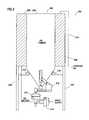
- FIG. 2is a cross sectional view of an Integrated Pre-gel Blender in accordance with a first exemplary embodiment of the present invention.
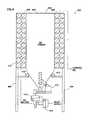
- FIG. 3is a cross sectional view of an Integrated Pre-gel Blender in accordance with a second exemplary embodiment of the present invention.
- FIG. 4is a cross sectional view of an Integrated Pre-gel Blender in accordance with a third exemplary embodiment of the present invention.
- FIG. 5depicts a close up view of the interface between the storage units and a blender in an Integrated Material Storage and Blending System in accordance with an exemplary embodiment of the present invention.
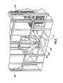
- FIG. 6is an isometric view of an Integrated Material Storage and Blending System in accordance with an exemplary embodiment of the present invention.
- the present inventionrelates generally to oilfield operations, and more particularly, to methods and systems for integral storage and blending of the materials used in oilfield operations.
- the present inventionis directed to an integrated material blending and storage system comprising: a storage unit; a blender located under the storage unit; wherein the blender is operable to receive a first input from the storage unit; a liquid additive storage module having a pump to maintain constant pressure at an outlet of the liquid additive storage module; wherein the blender is operable to receive a second input from the liquid additive storage module; and a pre-gel blender; wherein the blender is operable to receive a third input from the pre-gel blender; wherein gravity directs the contents of the storage unit, the liquid additive storage module and the pre-gel blender to the blender; a first pump; and a second pump; wherein the first pump directs the contents of the blender to the second pump; and wherein the second pump directs the contents of the blender down hole; wherein at least one of the first pump and the second pump is powered by one of natural gas and electricity.
- the present inventionis directed to a modular integrated material blending and storage system comprising: a first module comprising a storage unit; a second module comprising a liquid additive storage unit and a pump for maintaining pressure at an outlet of the liquid additive storage unit; and a third module comprising a pre-gel blender; wherein an output of each of the first module, the second module and the third module is located above a blender; and wherein gravity directs the contents of the first module, the second module and the third module to the blender; a pump; wherein the pump directs the output of the blender to a desired down hole location; and wherein the pump is powered by one of natural gas and electricity.
- the present inventionrelates generally to oilfield operations, and more particularly, to methods and systems for integral storage and blending of the materials used in oilfield operations.
- the IMSBS 100includes a number of storage units 102 .
- the storage units 102may contain sand, proppants or other solid materials used to prepare a desired well treatment fluid.
- the storage units 102may be connected to load sensors (not shown) to monitor the reaction forces at the legs of the storage units 102 .
- the load sensor readingsmay then be used to monitor the change in weight, mass and/or volume of materials in the storage units 102 .
- the change in weight, mass or volumecan be used to control the metering of material from the storage units 102 during well treatment operations.
- the load sensorsmay be used to ensure the availability of materials during oilfield operations.
- load cellsmay be used as load sensors. Electronic load cells are preferred for their accuracy and are well known in the art, but other types of force-measuring devices may be used.
- load-sensing devicecan be used in place of or in conjunction with a load cell.
- suitable load-measuring devicesinclude weight-, mass-, pressure- or force-measuring devices such as hydraulic load cells, scales, load pins, dual sheer beam load cells, strain gauges and pressure transducers.
- Standard load cellsare available in various ranges such as 0-5000 pounds, 0-10000 pounds, etc.
- the load sensorsmay be communicatively coupled to an information handling system 104 which may process the load sensor readings. While FIG. 1 depicts a separate information handling system 104 for each storage unit 102 , as would be appreciated by those of ordinary skill in the art, with the benefit of this disclosure, a single information handling system may be used for all or any combination of the storage units 102 . Although FIG. 1 depicts a separate information handling system 104 for each storage unit 102 , as would be appreciated by those of ordinary skill in the art, with the benefit of this disclosure, a single information handling system may be used for all or any combination of the storage units 102 . Although FIG.
- the information handling system 104may include any instrumentality or aggregate of instrumentalities operable to compute, classify, process, transmit, receive, retrieve, originate, switch, store, display, manifest, detect, record, reproduce, handle, or utilize any form of information, intelligence, or data for business, scientific, control, or other purposes.
- the information handling system 104may be a network storage device, or any other suitable device and may vary in size, shape, performance, functionality, and price.
- the information handling system 104may be used to monitor the amount of materials in the storage units 102 over time and/or alert a user when the contents of a storage unit 102 reaches a threshold level.
- the usermay designate a desired sampling interval at which the information handling system 104 may take a reading of the load sensors.
- the information handling system 104may then compare the load sensor readings to the threshold value to determine if the threshold value is reached. If the threshold value is reached, the information handling system 104 may alert the user. In one embodiment, the information handling system 104 may provide a real-time visual depiction of the amount of materials contained in the storage units 102 . Moreover, as would be appreciated by those of ordinary skill in the art, with the benefit of this disclosure, the load sensors may be coupled to the information handling system 104 through a wired or wireless (not shown) connection.
- the IMSBS 100may also include one or more Integrated Pre-gel Blenders (IPB) 106 .
- the IPB 106may be used for preparing any desirable well treatment fluids such as a fracturing fluid, a sand control fluid or any other fluid requiring hydration time.
- FIG. 2depicts an IPB 200 in accordance with an exemplary embodiment of the present invention.
- the IPB 200comprises a pre-gel storage unit 202 resting on legs 204 .
- the pre-gel storage unit 202may be a storage bin, a tank, or any other desirable storage unit.
- the pre-gel storage unit 202may contain the gel powder used for preparing the gelled fracturing fluid.
- the gel powdermay comprise a dry polymer.
- the dry polymermay be any agent used to enhance fluid properties, including, but not limited to, wg18, wg35, wg36 (available from Halliburton Energy Services of Duncan, Okla.) or any other guar or modified guar gelling agents.
- the materials from the pre-gel storage unit 202may be directed to a mixer 206 as a first input through a feeder 208 .
- the mixer 206may be a growler mixer and the feeder 208 may be a screw feeder which may be used to provide a volumetric metering of the materials directed to the mixer 206 .
- a water pump 210may be used to supply water to the mixer 206 as a second input.
- a variety of different pumpsmay be used as the water pump 210 depending on the user preferences.
- the water pump 210may be a centrifugal pump, a progressive cavity pump, a gear pump or a peristaltic pump.
- the mixer 206mixes the gel powder from the pre-gel storage unit 202 with the water from the water pump 210 at the desired concentration and the finished gel is discharged from the mixer 206 and may be directed to a storage unit, such as an external frac tank (not shown), for hydration.
- the finished gelmay then be directed to a blender 108 in the IMSBS 100 .
- the legs 204 of the pre-gel storage unit 202are attached to load sensors 212 to monitor the reaction forces at the legs 204 .
- the load sensor 212 readingsmay then be used to monitor the change in weight, mass and/or volume of materials in the pre-gel storage unit 202 .
- the change in weight, mass or volumecan be used to control the metering of material from the pre-gel storage unit 202 at a given set point.
- the load sensors 212may be used to ensure the availability of materials during oilfield operations.
- load cellsmay be used as load sensors 212 . Electronic load cells are preferred for their accuracy and are well known in the art, but other types of force-measuring devices may be used.
- load-sensing devicecan be used in place of or in conjunction with a load cell.
- suitable load-measuring devicesinclude weight-, mass-, pressure- or force-measuring devices such as hydraulic load cells, scales, load pins, dual sheer beam load cells, strain gauges and pressure transducers.
- Standard load cellsare available in various ranges such as 0-5000 pounds, 0-10000 pounds, etc.
- the load sensors 212may be communicatively coupled to an information handling system 214 which may process the load sensor readings.
- FIG. 2depicts a personal computer as the information handling system 214 , as would be apparent to those of ordinary skill in the art, with the benefit of this disclosure, the information handling system 214 may include any instrumentality or aggregate of instrumentalities operable to compute, classify, process, transmit, receive, retrieve, originate, switch, store, display, manifest, detect, record, reproduce, handle, or utilize any form of information, intelligence, or data for business, scientific, control, or other purposes.
- the information handling system 214may be a network storage device, or any other suitable device and may vary in size, shape, performance, functionality, and price.
- the information handling system 214may be used to monitor the amount of materials in the pre-gel storage unit 202 over time and/or alert a user when the contents of the pre-gel storage unit 202 reaches a threshold level.
- the usermay designate a desired sampling interval at which the information handling system 214 may take a reading of the load sensors 212 .
- the information handling system 214may then compare the load sensor readings to the threshold value to determine if the threshold value is reached. If the threshold value is reached, the information handling system 214 may alert the user.
- the information handling system 214may provide a real-time visual depiction of the amount of materials contained in the pre-gel storage unit 202 .
- the load sensors 212may be coupled to the information handling system 214 through a wired or wireless (not shown) connection.
- the dry polymer materialmay be replaced with a Liquid Gel Concentrate (“LGC”) material that consists of the dry polymer mixed in a carrier fluid.
- LGCLiquid Gel Concentrate
- the feeder and mixer mechanismswould be replaced with a metering pump of suitable construction to inject the LGC into the water stream, thus initiating the hydration process.
- FIG. 3depicts an IPB in accordance with a second exemplary embodiment of the present invention, denoted generally by reference numeral 300 .
- the IPB 300comprises a pre-gel storage unit 302 resting on legs 308 .
- the pre-gel storage unit 302 in this embodimentmay include a central core 304 for storage and handling of materials.
- the central core 304may be used to store a dry gel powder for making gelled fracturing fluids.
- the pre-gel storage unit 302may further comprise an annular space 306 for hydration volume.
- the gel powdermay comprise a dry polymer.
- the dry polymermay comprise a number of different materials, including, but not limited to, wg18, wg35, wg36 (available from Halliburton Energy Services of Duncan, Okla.) or any other guar or modified guar gelling agents.
- the materials from the central core 304 of the pre-gel storage unit 302may be directed to a mixer 310 as a first input through a feeder 312 .
- the mixer 310may be a growler mixer and the feeder 312 may be a screw feeder which may be used to provide a volumetric metering of the materials directed to the mixer 310 .
- a water pump 314may be used to supply water to the mixer 310 as a second input.
- a variety of different pumpsmay be used as the water pump 314 depending on the user preferences.
- the water pump 314may be a centrifugal pump, a progressive cavity pump, a gear pump or a peristaltic pump.
- the mixer 310mixes the gel powder from the pre-gel storage unit 302 with the water from the water pump 314 at the desired concentration and the finished gel is discharged from the mixer 310 .
- the pre-gel storage unit 302may rest on load sensors 316 which may be used for monitoring the amount of materials in the pre-gel storage unit 302 .
- the change in weight, mass or volumecan be used to control the metering of material from the pre-gel storage unit 302 at a given set point.
- the gel having the desired concentrationis discharged from the mixer 310 , it is directed to the annular space 306 .
- the gel mixtureis maintained in the annular space 306 for hydration. Once sufficient time has passed and the gel is hydrated, it is discharged from the annular space 306 through the discharge line 318 .
- FIG. 4depicts a cross sectional view of a storage unit in an IPB 400 in accordance with a third exemplary embodiment of the present invention.
- the IPB 400comprises a pre-gel storage unit 402 resting on legs 404 .
- the pre-gel storage unit 402 in this embodimentmay include a central core 406 for storage and handling of materials.
- the central core 406may be used to store a dry gel powder for making gelled fracturing fluids.
- the gel powdermay comprise a dry polymer.
- the dry polymermay be any agent used to enhance fluid properties, including, but not limited to, wg18, wg35, wg36 (available from Halliburton Energy Services of Duncan, Okla.) or any other guar or modified guar gelling agents.
- the pre-gel storage unit 402may further comprise an annular space 408 which may be used as a hydration volume.
- the annular space 408contains a tubular hydration loop 410 .
- the materials from the central core 406 of the pre-gel storage unit 402may be directed to a mixer 412 as a first input through a feeder 414 .
- the mixer 412may be a growler mixer and the feeder 414 may be a screw feeder which may be used to provide a volumetric metering of the materials directed to the mixer 412 .
- a water pump 416may be used to supply water to the mixer 412 as a second input.
- a variety of different pumpsmay be used as the water pump 416 depending on the user preferences.
- the water pump 416may be a centrifugal pump, a progressive cavity pump, a gear pump or a peristaltic pump.
- the mixer 412mixes the gel powder from the pre-gel storage unit 402 with the water from the water pump 416 at the desired concentration and the finished gel is discharged from the mixer 412 .
- the pre-gel storage unit 402may rest on load sensors 418 which may be used for monitoring the amount of materials in the pre-gel storage unit 402 .
- the change in weight, mass or volumecan be used to control the metering of material from the pre-gel storage unit 402 at a given set point.
- the portions of the gel mixtureare discharged from the mixer 412 at different points in time, and accordingly, will be hydrated at different times. Specifically, a portion of the gel mixture discharged from the mixer 412 into the annular space 408 at a first point in time, t 1 , will be sufficiently hydrated before a portion of the gel mixture which is discharged into the annular space 408 at a second point in time, t 2 .
- a tubular hydration loop 410is inserted in the annular space 408 to direct the flow of the gel as it is being hydrated.
- the tubular hydration loop 410may need to be cleaned during a job or between jobs.
- the tubular hydration loop 410may be cleaned by passing a fluid such as water through it.
- a pigging devicemay be used to clean the tubular hydration loop 410 .
- the IMSBS 100may include one or more blenders 108 located at the bottom of the storage units 102 .
- multiple storage units 102may be positioned above a blender 108 and be operable to deliver solid materials to the blender 108 .
- FIG. 5depicts a close up view of the interface between the storage units 102 and the blender 108 . As depicted in FIG. 5 , gravity directs the solid materials from the storage units 102 to the blender 108 through the hopper 502 , obviating the need for a conveyer system.
- the IMSBS 100may also include one or more liquid additive storage modules 110 .
- the liquid additive storage modules 110may contain a fluid used in preparing the desired well treatment fluid. As would be appreciated by those of ordinary skill in the art, with the benefit of this disclosure, depending on the well treatment fluid being prepared, a number of different fluids may be stored in the liquid additive storage modules 110 . Such fluids may include, but are not limited to, surfactants, acids, cross-linkers, breakers, or any other desirable chemical additives. As discussed in detail with respect to storage units 102 , load sensors (not shown) may be used to monitor the amount of fluid in the liquid additive storage modules 110 in real time and meter the amount of fluids delivered to the blender 108 .
- a pumpmay be used to circulate the contents and maintain constant pressure at the head of the liquid additive storage modules 110 . Because the pressure of the fluid at the outlet of the liquid additive storage modules 110 is kept constant and the blender 108 is located beneath the liquid additive storage modules 110 , gravity assists in directing the fluid from the liquid additive storage modules 110 to the blender 108 , thereby obviating the need for a pump or other conveyor systems to transfer the fluid.
- the blender 108includes a fluid inlet 112 and an optional water inlet 504 . Once the desired materials are mixed in the blender 108 , the materials exit the blender 108 through the outlet 114 .
- a base gelis prepared in the IPB 106 .
- the gel prepared in the IPBmay be directed to an annular space 406 for hydration.
- the annular spacemay further include a hydration loop 410 .
- the resulting gel from the IPB 106may be pumped to the centrally located blender 108 .
- Each of the base gel, the fluid modifying agents and the solid components used in preparing a desired well treatment fluidmay be metered out from the IPB 106 , the liquid additive storage module 110 and the storage unit 102 , respectively.
- the blender 108mixes the base gel with other fluid modifying agents from the liquid additive storage modules 110 and the solid component(s) from the storage units 102 .
- the solid componentmay be a dry proppant.
- the dry proppantmay be gravity fed into the blending tub through metering gates.
- the pump usedmay be a centrifugal pump, a progressive cavity pump, a gear pump or a peristaltic pump.
- chemicals from the liquid additive storage modules 110may be injected in the manifolds leading to and exiting the blender 108 in order to bring them closer to the centrifugal pumps and away from other chemicals when there are compatibility or reaction issues.
- the mixing and blending processmay be accomplished at the required rate dictated by the job parameters.
- pumps that transfer the final slurry to the down hole pumpstypically have a high horsepower requirement.
- the transfer pumpmay be powered by a natural gas fired engine or a natural gas fired generator set.
- the transfer pumpmay be powered by electricity from a power grid.
- the down hole pumpspump the slurry through the high pressure ground manifold to the well head and down hole.
- the down hole pumpsmay be powered by a natural gas fired engine, a natural gas fired generator set or electricity from a power grid. The down hole pumps typically account for over two third of the horsepower on location, thereby reducing the carbon footprint of the overall operations.
- the natural gas used to power the transfer pumps, the down hole pumps or the other system componentsmay be obtained from the field on which the subterranean operations are being performed.
- the natural gasmay be converted to liquefied natural gas and used to power pumps and other equipment that would typically be powered by diesel fuel.
- the natural gasmay be used to provide power through generator sets.
- the natural gas from the fieldmay undergo conditioning before being used to provide power to the pumps and other equipment.
- the conditioning processmay include cleaning the natural gas, compressing the natural gas in compressor stations and if necessary, removing any water contained therein.
- the IMSBSmay include a different number of storage units 102 , IPBs 106 and/or liquid additive storage modules 110 , depending on the system requirements.
- the IMSBSmay include three storage units, one IPB and one liquid additive storage module.
- FIG. 6depicts an isometric view of IMSBS in accordance with an exemplary embodiment of the present invention, denoted generally with reference numeral 600 .
- each of the storage units 602 , each of the liquid additive storage modules 604 and each of the IPBs 606may be arranged as an individual module.
- one or more of the storage units 602 , the liquid additive storage modules 604 and the IPBs 606may include a latch system which is couplable to a truck or trailer which may be used for transporting the module.
- the storage units 602may be a self-erecting storage unit as disclosed in U.S. patent application Ser. No.
- the storage units 602may be specially adapted to connect to a vehicle which may be used to lower, raise and transport the storage unit 602 .
- the storage unit 602may be erected and filled with a predetermined amount of a desired material.
- a similar designmay be used in conjunction with each of the modules of the IMSBS 600 disclosed herein in order to transport the modules to and from a job site.
- Dry materialssuch as proppants or gel powder may then be filled pneumatically to the desired level and liquid chemicals may be pumped into the various storage tanks.
- Load sensors(not shown) may be used to monitor the amount of materials added to the storage units 602 , the liquid additive storage modules 604 and the IPBs 606 in real time.
- an IMSBS 600 in accordance with an exemplary embodiment of the present inventionwhich permits accurate, real-time monitoring of the contents of the storage units 602 , the liquid additive storage modules 604 and/or the IPBs 606 provides several advantages. For instance, an operator may use the amount of materials remaining in the storage units 602 , the liquid additive storage modules 604 and/or the IPBs 606 as a quality control mechanism to ensure that material consumption is in line with the job requirements. Additionally, the accurate, real-time monitoring of material consumption expedites the operator's ability to determine the expenses associated with a job.
- the different equipment used in an IMSBS in accordance with the present inventionmay be powered by any suitable power source.
- the equipmentmay be powered by a combustion engine, electric power supply which may be provided by an on-site generator or by a hydraulic power supply.
Landscapes
- Engineering & Computer Science (AREA)
- Life Sciences & Earth Sciences (AREA)
- Geology (AREA)
- Mining & Mineral Resources (AREA)
- Physics & Mathematics (AREA)
- Environmental & Geological Engineering (AREA)
- Fluid Mechanics (AREA)
- General Life Sciences & Earth Sciences (AREA)
- Geochemistry & Mineralogy (AREA)
- Mechanical Engineering (AREA)
- Accessories For Mixers (AREA)
Abstract
Description
This is an application for reissue of U.S. Pat. No. 8,834,012, application Ser. No. 12/774,959, filed on May 6, 2010.
This application is a continuation-in-part of U.S. patent application Ser. No. 12/557,730, filed Sep. 11, 2009, now U.S. Pat. No. 8,444,312 entitled “Improved Methods and Systems for Integral Blending and Storage of Materials,” the entire disclosure of which is incorporated herein by reference.
The present invention relates generally to oilfield operations, and more particularly, to methods and systems for integral storage and blending of the materials used in oilfield operations.
Oilfield operations are conducted in a variety of different locations and involve a number of equipments, depending on the operations at hand. The requisite materials for the different operations are often hauled to and stored at the well site where the operations are to be performed.
Considering the number of equipments necessary for performing oilfield operations and ground conditions at different oilfield locations, space availability is often a constraint. For instance, in well treatment operations such as fracturing operations, several wells may be serviced from a common jobsite pad. In such operations, the necessary equipment is not moved from well site to well site. Instead, the equipment may be located at a central work pad and the required treating fluids may be pumped to the different well sites from this central location. Accordingly, the bulk of materials required at a centralized work pad may be enormous, further limiting space availability.
Typically, in modem well treatment operations, equipment is mounted on a truck or a trailer and brought to location and set up. The storage units used are filled with the material required to prepare the well treatment fluid and perform the well treatment. In order to prepare the well treatment fluid, the material used is then transferred from the storage units to one or more blenders to prepare the desired well treatment fluid which may then be pumped down hole.
For instance, in conventional fracturing operations a blender and a pre-gel blender are set between the high pressure pumping units and the storage units which contain the dry materials and chemicals used. The dry materials and the chemicals used in the fracturing operations are then transferred, often over a long distance, from the storage units to the mixing and blending equipments. Once the treating process is initiated, the solid materials and chemicals are typically conveyed to the blender by a combination of conveyer belts, screw type conveyers and a series of hoses and pumps.
The equipment used for transferring the dry materials and chemicals from the storage units to the blender occupy valuable space at the job site. Additionally, the transfer of dry materials and chemicals to the blender consumes a significant amount of energy as well as other system resources and contributes to the carbon foot print of the job site. Moreover, in typical “on land” operations the entire equipment spread including the high horsepower pumping units are powered by diesel fired engines and the bulk material metering, conveying and pumping is done with diesel fired hydraulic systems. Emissions from the equipment that is powered by diesel fuel contributes to the overall carbon footprint and adversely affects the environment.
Some specific example embodiments of the disclosure may be understood by referring, in part, to the following description and the accompanying drawings.
While embodiments of this disclosure have been depicted and described and are defined by reference to example embodiments of the disclosure, such references do not imply a limitation on the disclosure, and no such limitation is to be inferred. The subject matter disclosed is capable of considerable modification, alteration, and equivalents in form and function, as will occur to those skilled in the pertinent art and having the benefit of this disclosure. The depicted and described embodiments of this disclosure are examples only, and not exhaustive of the scope of the disclosure.
The present invention relates generally to oilfield operations, and more particularly, to methods and systems for integral storage and blending of the materials used in oilfield operations.
In one embodiment, the present invention is directed to an integrated material blending and storage system comprising: a storage unit; a blender located under the storage unit; wherein the blender is operable to receive a first input from the storage unit; a liquid additive storage module having a pump to maintain constant pressure at an outlet of the liquid additive storage module; wherein the blender is operable to receive a second input from the liquid additive storage module; and a pre-gel blender; wherein the blender is operable to receive a third input from the pre-gel blender; wherein gravity directs the contents of the storage unit, the liquid additive storage module and the pre-gel blender to the blender; a first pump; and a second pump; wherein the first pump directs the contents of the blender to the second pump; and wherein the second pump directs the contents of the blender down hole; wherein at least one of the first pump and the second pump is powered by one of natural gas and electricity.
In another exemplary embodiment, the present invention is directed to a modular integrated material blending and storage system comprising: a first module comprising a storage unit; a second module comprising a liquid additive storage unit and a pump for maintaining pressure at an outlet of the liquid additive storage unit; and a third module comprising a pre-gel blender; wherein an output of each of the first module, the second module and the third module is located above a blender; and wherein gravity directs the contents of the first module, the second module and the third module to the blender; a pump; wherein the pump directs the output of the blender to a desired down hole location; and wherein the pump is powered by one of natural gas and electricity.
The features and advantages of the present disclosure will be readily apparent to those skilled in the art upon a reading of the description of exemplary embodiments, which follows.
The present invention relates generally to oilfield operations, and more particularly, to methods and systems for integral storage and blending of the materials used in oilfield operations.
Turning now toFIG. 1 , an Integrated Material Storage and Blending System (IMSBS) in accordance with an exemplary embodiment of the present invention is depicted generally withreference numeral 100. The IMSBS100 includes a number ofstorage units 102. Thestorage units 102 may contain sand, proppants or other solid materials used to prepare a desired well treatment fluid.
In one exemplary embodiment, thestorage units 102 may be connected to load sensors (not shown) to monitor the reaction forces at the legs of thestorage units 102. The load sensor readings may then be used to monitor the change in weight, mass and/or volume of materials in thestorage units 102. The change in weight, mass or volume can be used to control the metering of material from thestorage units 102 during well treatment operations. As a result, the load sensors may be used to ensure the availability of materials during oilfield operations. In one exemplary embodiment, load cells may be used as load sensors. Electronic load cells are preferred for their accuracy and are well known in the art, but other types of force-measuring devices may be used. As will be apparent to one skilled in the art, however, any type of load-sensing device can be used in place of or in conjunction with a load cell. Examples of suitable load-measuring devices include weight-, mass-, pressure- or force-measuring devices such as hydraulic load cells, scales, load pins, dual sheer beam load cells, strain gauges and pressure transducers. Standard load cells are available in various ranges such as 0-5000 pounds, 0-10000 pounds, etc.
In one exemplary embodiment the load sensors may be communicatively coupled to aninformation handling system 104 which may process the load sensor readings. WhileFIG. 1 depicts a separateinformation handling system 104 for eachstorage unit 102, as would be appreciated by those of ordinary skill in the art, with the benefit of this disclosure, a single information handling system may be used for all or any combination of thestorage units 102. AlthoughFIG. 1 depicts a personal computer as theinformation handling system 104, as would be apparent to those of ordinary skill in the art, with the benefit of this disclosure, theinformation handling system 104 may include any instrumentality or aggregate of instrumentalities operable to compute, classify, process, transmit, receive, retrieve, originate, switch, store, display, manifest, detect, record, reproduce, handle, or utilize any form of information, intelligence, or data for business, scientific, control, or other purposes. For example, theinformation handling system 104 may be a network storage device, or any other suitable device and may vary in size, shape, performance, functionality, and price. For instance, in one exemplary embodiment, theinformation handling system 104 may be used to monitor the amount of materials in thestorage units 102 over time and/or alert a user when the contents of astorage unit 102 reaches a threshold level. The user may designate a desired sampling interval at which theinformation handling system 104 may take a reading of the load sensors.
Theinformation handling system 104 may then compare the load sensor readings to the threshold value to determine if the threshold value is reached. If the threshold value is reached, theinformation handling system 104 may alert the user. In one embodiment, theinformation handling system 104 may provide a real-time visual depiction of the amount of materials contained in thestorage units 102. Moreover, as would be appreciated by those of ordinary skill in the art, with the benefit of this disclosure, the load sensors may be coupled to theinformation handling system 104 through a wired or wireless (not shown) connection.
As depicted inFIG. 1 , theIMSBS 100 may also include one or more Integrated Pre-gel Blenders (IPB)106. TheIPB 106 may be used for preparing any desirable well treatment fluids such as a fracturing fluid, a sand control fluid or any other fluid requiring hydration time.
In one exemplary embodiment, thelegs 204 of thepre-gel storage unit 202 are attached to loadsensors 212 to monitor the reaction forces at thelegs 204. Theload sensor 212 readings may then be used to monitor the change in weight, mass and/or volume of materials in thepre-gel storage unit 202. The change in weight, mass or volume can be used to control the metering of material from thepre-gel storage unit 202 at a given set point. As a result, theload sensors 212 may be used to ensure the availability of materials during oilfield operations. In one exemplary embodiment, load cells may be used asload sensors 212. Electronic load cells are preferred for their accuracy and are well known in the art, but other types of force-measuring devices may be used. As will be apparent to one skilled in the art, however, any type of load-sensing device can be used in place of or in conjunction with a load cell. Examples of suitable load-measuring devices include weight-, mass-, pressure- or force-measuring devices such as hydraulic load cells, scales, load pins, dual sheer beam load cells, strain gauges and pressure transducers. Standard load cells are available in various ranges such as 0-5000 pounds, 0-10000 pounds, etc.
In one exemplary embodiment theload sensors 212 may be communicatively coupled to aninformation handling system 214 which may process the load sensor readings. AlthoughFIG. 2 depicts a personal computer as theinformation handling system 214, as would be apparent to those of ordinary skill in the art, with the benefit of this disclosure, theinformation handling system 214 may include any instrumentality or aggregate of instrumentalities operable to compute, classify, process, transmit, receive, retrieve, originate, switch, store, display, manifest, detect, record, reproduce, handle, or utilize any form of information, intelligence, or data for business, scientific, control, or other purposes. For example, theinformation handling system 214 may be a network storage device, or any other suitable device and may vary in size, shape, performance, functionality, and price. For instance, in one exemplary embodiment, theinformation handling system 214 may be used to monitor the amount of materials in thepre-gel storage unit 202 over time and/or alert a user when the contents of thepre-gel storage unit 202 reaches a threshold level. The user may designate a desired sampling interval at which theinformation handling system 214 may take a reading of theload sensors 212. Theinformation handling system 214 may then compare the load sensor readings to the threshold value to determine if the threshold value is reached. If the threshold value is reached, theinformation handling system 214 may alert the user. In one embodiment, theinformation handling system 214 may provide a real-time visual depiction of the amount of materials contained in thepre-gel storage unit 202.
Moreover, as would be appreciated by those of ordinary skill in the art, with the benefit of this disclosure, theload sensors 212 may be coupled to theinformation handling system 214 through a wired or wireless (not shown) connection. As would be appreciated by those of ordinary skill in the art, with the benefit of this disclosure, in one exemplary embodiment, the dry polymer material may be replaced with a Liquid Gel Concentrate (“LGC”) material that consists of the dry polymer mixed in a carrier fluid. In this exemplary embodiment, the feeder and mixer mechanisms would be replaced with a metering pump of suitable construction to inject the LGC into the water stream, thus initiating the hydration process.
The materials from thecentral core 304 of thepre-gel storage unit 302 may be directed to amixer 310 as a first input through afeeder 312. As would be appreciated by those of ordinary skill in the art, with the benefit of this disclosure, in one embodiment, themixer 310 may be a growler mixer and thefeeder 312 may be a screw feeder which may be used to provide a volumetric metering of the materials directed to themixer 310. Awater pump 314 may be used to supply water to themixer 310 as a second input. A variety of different pumps may be used as thewater pump 314 depending on the user preferences. For instance, thewater pump 314 may be a centrifugal pump, a progressive cavity pump, a gear pump or a peristaltic pump. Themixer 310 mixes the gel powder from thepre-gel storage unit 302 with the water from thewater pump 314 at the desired concentration and the finished gel is discharged from themixer 310. As discussed above with reference to thestorage units 102, thepre-gel storage unit 302 may rest onload sensors 316 which may be used for monitoring the amount of materials in thepre-gel storage unit 302. The change in weight, mass or volume can be used to control the metering of material from thepre-gel storage unit 302 at a given set point.
In this embodiment, once the gel having the desired concentration is discharged from themixer 310, it is directed to theannular space 306. The gel mixture is maintained in theannular space 306 for hydration. Once sufficient time has passed and the gel is hydrated, it is discharged from theannular space 306 through thedischarge line 318.
The materials from thecentral core 406 of thepre-gel storage unit 402 may be directed to amixer 412 as a first input through afeeder 414. As would be appreciated by those of ordinary skill in the art, with the benefit of this disclosure, in one embodiment, themixer 412 may be a growler mixer and thefeeder 414 may be a screw feeder which may be used to provide a volumetric metering of the materials directed to themixer 412. Awater pump 416 may be used to supply water to themixer 412 as a second input. A variety of different pumps may be used as thewater pump 416 depending on the user preferences. For instance, thewater pump 416 may be a centrifugal pump, a progressive cavity pump, a gear pump or a peristaltic pump. Themixer 412 mixes the gel powder from thepre-gel storage unit 402 with the water from thewater pump 416 at the desired concentration and the finished gel is discharged from themixer 412. As discussed above with reference toFIG. 1 , thepre-gel storage unit 402 may rest onload sensors 418 which may be used for monitoring the amount of materials in thepre-gel storage unit 402. The change in weight, mass or volume can be used to control the metering of material from thepre-gel storage unit 402 at a given set point.
In this embodiment, once the gel having the desired concentration is discharged from themixer 412, it is directed to theannular space 408 where it enters thetubular hydration loop 410. As would be appreciated by those of ordinary skill in the art, with the benefit of this disclosure, the portions of the gel mixture are discharged from themixer 412 at different points in time, and accordingly, will be hydrated at different times. Specifically, a portion of the gel mixture discharged from themixer 412 into theannular space 408 at a first point in time, t1, will be sufficiently hydrated before a portion of the gel mixture which is discharged into theannular space 408 at a second point in time, t2. Accordingly, it is desirable to ensure that the gel mixture is transferred through theannular space 408 in a First-In-First-Out (FIFO) mode. To that end, in the third exemplary embodiment, atubular hydration loop 410 is inserted in theannular space 408 to direct the flow of the gel as it is being hydrated.
As would be appreciated by those of ordinary skill in the art, with the benefit of this disclosure, in order to achieve optimal performance, thetubular hydration loop 410 may need to be cleaned during a job or between jobs. In one embodiment, thetubular hydration loop 410 may be cleaned by passing a fluid such as water through it. In another exemplary embodiment, a pigging device may be used to clean thetubular hydration loop 410.
Returning toFIG. 1 , theIMSBS 100 may include one ormore blenders 108 located at the bottom of thestorage units 102. In one embodiment,multiple storage units 102 may be positioned above ablender 108 and be operable to deliver solid materials to theblender 108.FIG. 5 depicts a close up view of the interface between thestorage units 102 and theblender 108. As depicted inFIG. 5 , gravity directs the solid materials from thestorage units 102 to theblender 108 through thehopper 502, obviating the need for a conveyer system.
Returning toFIG. 1 , theIMSBS 100 may also include one or more liquidadditive storage modules 110. The liquidadditive storage modules 110 may contain a fluid used in preparing the desired well treatment fluid. As would be appreciated by those of ordinary skill in the art, with the benefit of this disclosure, depending on the well treatment fluid being prepared, a number of different fluids may be stored in the liquidadditive storage modules 110. Such fluids may include, but are not limited to, surfactants, acids, cross-linkers, breakers, or any other desirable chemical additives. As discussed in detail with respect tostorage units 102, load sensors (not shown) may be used to monitor the amount of fluid in the liquidadditive storage modules 110 in real time and meter the amount of fluids delivered to theblender 108. As would be appreciated by those of ordinary skill in the art, with the benefit of this disclosure, a pump may be used to circulate the contents and maintain constant pressure at the head of the liquidadditive storage modules 110. Because the pressure of the fluid at the outlet of the liquidadditive storage modules 110 is kept constant and theblender 108 is located beneath the liquidadditive storage modules 110, gravity assists in directing the fluid from the liquidadditive storage modules 110 to theblender 108, thereby obviating the need for a pump or other conveyor systems to transfer the fluid.
As depicted in more detail inFIG. 5 , theblender 108 includes afluid inlet 112 and anoptional water inlet 504. Once the desired materials are mixed in theblender 108, the materials exit theblender 108 through theoutlet 114.
In one embodiment, when preparing a well treatment fluid, a base gel is prepared in theIPB 106. In one embodiment, the gel prepared in the IPB may be directed to anannular space 406 for hydration. In another exemplary embodiment, the annular space may further include ahydration loop 410. In one exemplary embodiment, the resulting gel from theIPB 106 may be pumped to the centrally locatedblender 108. Each of the base gel, the fluid modifying agents and the solid components used in preparing a desired well treatment fluid may be metered out from theIPB 106, the liquidadditive storage module 110 and thestorage unit 102, respectively. Theblender 108 mixes the base gel with other fluid modifying agents from the liquidadditive storage modules 110 and the solid component(s) from thestorage units 102. As would be appreciated by those of ordinary skill in the art, with the benefit of this disclosure, when preparing a fracturing fluid the solid component may be a dry proppant. In one exemplary embodiment, the dry proppant may be gravity fed into the blending tub through metering gates. Once theblender 108 mixes the base gel, the fluid modifying agent and the solid component(s), the resulting well treatment fluid may be directed to a down hole pump (not shown) through theoutlet 114. A variety of different pumps may be used to pump the output of the IMSBS down hole. For instance, the pump used may be a centrifugal pump, a progressive cavity pump, a gear pump or a peristaltic pump. In one exemplary embodiment, chemicals from the liquidadditive storage modules 110 may be injected in the manifolds leading to and exiting theblender 108 in order to bring them closer to the centrifugal pumps and away from other chemicals when there are compatibility or reaction issues.
As would be appreciated by those of ordinary skill in the art, with the benefit of this disclosure, the mixing and blending process may be accomplished at the required rate dictated by the job parameters. As a result, pumps that transfer the final slurry to the down hole pumps typically have a high horsepower requirement. In one exemplary embodiment, the transfer pump may be powered by a natural gas fired engine or a natural gas fired generator set. In another exemplary embodiment, the transfer pump may be powered by electricity from a power grid. Once the fluid system is mixed and blended with proppant and other fluid modifiers it is boosted to the high horsepower down hole pumps. The down hole pumps pump the slurry through the high pressure ground manifold to the well head and down hole. In one embodiment, the down hole pumps may be powered by a natural gas fired engine, a natural gas fired generator set or electricity from a power grid. The down hole pumps typically account for over two third of the horsepower on location, thereby reducing the carbon footprint of the overall operations.
In one exemplary embodiment, the natural gas used to power the transfer pumps, the down hole pumps or the other system components may be obtained from the field on which the subterranean operations are being performed. In one embodiment, the natural gas may be converted to liquefied natural gas and used to power pumps and other equipment that would typically be powered by diesel fuel. In another embodiment, the natural gas may be used to provide power through generator sets. The natural gas from the field may undergo conditioning before being used to provide power to the pumps and other equipment. The conditioning process may include cleaning the natural gas, compressing the natural gas in compressor stations and if necessary, removing any water contained therein.
As would be appreciated by those of ordinary skill in the art, with the benefit of this disclosure, the IMSBS may include a different number ofstorage units 102,IPBs 106 and/or liquidadditive storage modules 110, depending on the system requirements. For instance, in another exemplary embodiment (not shown), the IMSBS may include three storage units, one IPB and one liquid additive storage module.
As would be appreciated by those of ordinary skill in the art, with the benefit of this disclosure, anIMSBS 600 in accordance with an exemplary embodiment of the present invention which permits accurate, real-time monitoring of the contents of thestorage units 602, the liquidadditive storage modules 604 and/or theIPBs 606 provides several advantages. For instance, an operator may use the amount of materials remaining in thestorage units 602, the liquidadditive storage modules 604 and/or theIPBs 606 as a quality control mechanism to ensure that material consumption is in line with the job requirements. Additionally, the accurate, real-time monitoring of material consumption expedites the operator's ability to determine the expenses associated with a job.
As would be appreciated by those of ordinary skill in the art, with the benefit of this disclosure, the different equipment used in an IMSBS in accordance with the present invention may be powered by any suitable power source. For instance, the equipment may be powered by a combustion engine, electric power supply which may be provided by an on-site generator or by a hydraulic power supply.
Therefore, the present invention is well-adapted to carry out the objects and attain the ends and advantages mentioned as well as those which are inherent therein. While the invention has been depicted and described by reference to exemplary embodiments of the invention, such a reference does not imply a limitation on the invention, and no such limitation is to be inferred. The invention is capable of considerable modification, alteration, and equivalents in form and function, as will occur to those ordinarily skilled in the pertinent arts and having the benefit of this disclosure. The depicted and described embodiments of the invention are exemplary only, and are not exhaustive of the scope of the invention. Consequently, the invention is intended to be limited only by the spirit and scope of the appended claims, giving full cognizance to equivalents in all respects. The terms in the claims have their plain, ordinary meaning unless otherwise explicitly and clearly defined by the patentee.
Claims (94)
1. An integrated material blending and storage system comprising:
a storage unit;
a blender located under the storage unit;
wherein the blender is operable to receive a first input from the storage unit through a hopper;
a liquid additive storage module having a first pump to maintain constant pressure at an outlet of the liquid additive storage module;
wherein the blender is operable to receive a second input from the liquid additive storage module; and
a pre-gel blender, wherein the pre-gel blender comprises at least a pre-gel storage unit resting on a leg, further wherein the pre-gel storage unit comprises a central core and an annular space, wherein the annular space hydrates the contents of the pre-gel blender;
wherein the blender is operable to receive a third input from the pre-gel blender;
wherein gravity directs the contents of the storage unit, the liquid additive storage module and the pre-gel blender to the blender;
a second pump; and
a third pump;
wherein the second pump directs the contents of the blender to the third pump; and
wherein the third pump directs the contents of the blender down hole;
wherein at least one of the second pump and the third pump is powered by one of natural gas and electricity.
2. The system ofclaim 1 , wherein the storage unit comprises a load sensor.
3. The system ofclaim 1 , wherein the pre-gel blender comprises:
a feeder coupling the pre-gel storage unit to a first input of a mixer;
a fourth pump coupled to a second input of the mixer;
wherein the pre-gel storage unit contains a solid component of a well treatment fluid;
wherein the feeder supplies the solid component of the well treatment fluid to the mixer;
wherein the fourth pump supplies a fluid component of the well treatment fluid to the mixer; and
wherein the mixer outputs a well treatment fluid.
4. The system ofclaim 3 , wherein the well treatment fluid is a gelled fracturing fluid.
5. The system ofclaim 4 , wherein the solid component is a gel powder.
6. The system ofclaim 4 , wherein the fluid component is water.
7. The system ofclaim 3 , wherein the central core contains the solid component of the well treatment fluid.
8. The system ofclaim 3 , wherein the well treatment fluid is directed to the annular space.
9. The system ofclaim 3 , wherein the annular space comprises a tubular hydration loop.
10. The system ofclaim 9 , wherein the well treatment fluid is directed from the mixer to the tubular hydration loop.
11. The system ofclaim 3 , wherein the well treatment fluid is selected from the group consisting of a fracturing fluid and a sand control fluid.
12. The system ofclaim 3 , further comprising a power source to power at least one of the feeder, the mixer and the pump.
13. The system ofclaim 12 , wherein the power source is selected from the group consisting of a combustion engine, an electric power supply and a hydraulic power supply.
14. The system ofclaim 13 , wherein one of the combustion engine, the electric power supply and the hydraulic power supply is powered by natural gas.
15. The system ofclaim 1 , further comprising a load sensor coupled to one of the storage unit, the liquid additive storage module or the pre-gel blender.
16. The system ofclaim 15 , further comprising an information handling system communicatively coupled to the load sensor.
17. The system ofclaim 15 , wherein the load sensor is a load cell.
18. The system ofclaim 15 , wherein a reading of the load sensor is used for quality control.
19. The system ofclaim 1 , wherein the electricity is derived from one of a power grid and a natural gas generator set.
20. A modular integrated material blending and storage system comprising:
a first module comprising a storage unit;
a second module comprising a liquid additive storage unit and a first pump for maintaining pressure at an outlet of the liquid additive storage unit; and
a third module comprising a pre-gel blender, wherein the pre-gel blender comprises at least a pre-gel storage unit resting on a leg, further wherein the pre-gel storage unit comprises a central core and an annular space, wherein the annular space hydrates the contents of the pre-gel blender;
wherein an output of each of the first module, the second module and the third module is located above a blender; and
wherein gravity directs the contents of the first module through a hopper, the second module and the third module to the blender;
a second pump;
wherein the second pump directs the output of the blender to a desired down hole location; and
wherein the second pump is powered by one of natural gas and electricity.
21. The system ofclaim 20 , wherein each of the first module, the second module and the third module is a self erecting module.
22. The system ofclaim 20 , wherein the third module comprises:
a feeder coupling the pre-gel storage unit to a first input of a mixer;
a third pump coupled to a second input of the mixer;
wherein the pre-gel storage unit contains a solid component of a well treatment fluid;
wherein the feeder supplies the solid component of the well treatment fluid to the mixer;
wherein the third pump supplies a fluid component of the well treatment fluid to the mixer; and
wherein the mixer outputs a well treatment fluid.
23. The system ofclaim 22 , wherein the well treatment fluid is directed to the blender.
24. The system ofclaim 20 , wherein the blender mixes the output of the first module, the second module and the third module.
25. The system ofclaim 20 , further comprising a fourth pump for pumping an output of the blender down hole.
26. The system ofclaim 25 , wherein the fourth pump is selected from the group consisting of a centrifugal pump, a progressive cavity pump, a gear pump and a peristaltic pump.
27. A system for preparing fluid for use at a well having a wellbore, the system comprising:
at least one storage unit adapted to connect to a vehicle for transportation;
at least one pre-gel blender having a pre-gel storage unit, wherein the pre-gel storage unit comprises a central core and an annular space;
at least one blender coupled to receive a component of a first fluid from the at least one storage unit through a hopper, the at least one blender having inputs from at least the at least one storage unit, and the at least one pre-gel blender;
at least one pump for applying pressure to the first fluid or a second fluid, and the at least one pump coupled to provide an input to the at least one blender; and
an electric power supply, including an electrical generator located on-site, providing electrical power to at least one of the at least one blender and the at least one pump.
28. The system of claim 27 wherein the pre-gel storage unit contains a gel powder.
29. The system of claim 27 wherein the pre-gel storage unit rests on at least one leg.
30. The system of claim 27 wherein the pre-gel storage unit comprises a space in which contents of the pre-gel storage unit are allowed to hydrate.
31. The system of claim 27 wherein contents of the pre-gel storage unit are allowed to hydrate in the annular space.
32. The system of claim 27 wherein the central core contains a gel powder.
33. The system of claim 32 wherein the gel powder from the pre-gel storage unit is allowed to hydrate in the annular space.
34. The system of claim 27 further comprising a liquid additive storage module, wherein the at least one blender further comprises an input from the liquid additive storage module.
35. The system of claim 34 wherein the pre-gel storage unit contains a gel powder.
36. The system of claim 34 wherein the pre-gel storage unit rests on at least one leg.
37. The system of claim 34 wherein the pre-gel storage unit comprises a space in which contents of the pre-gel storage unit are allowed to hydrate.
38. The system of claim 34 wherein contents of the pre-gel storage unit are allowed to hydrate in the annular space.
39. The system of claim 34 wherein the central core contains a gel powder.
40. The system of claim 39 wherein the gel powder from the pre-gel storage unit is allowed to hydrate in the annular space.
41. The system of claim 39 wherein the pre-gel storage unit comprises a tubular hydration loop in which contents of the pre-gel storage unit are allowed to hydrate.
42. The system of claim 41 wherein the tubular hydration loop is located in an annular space of the pre-gel storage unit.
43. The system of claim 27 wherein a combustion engine provides power to the system.
44. The system of claim 27 wherein a hydraulic power supply provides power to the system.
45. A system comprising:
at least one storage unit;
at least one pre-gel blender;
at least one pre-gel storage unit coupled to the at least one pre-gel blender, wherein the at least one pre-gel storage unit comprises a central core and an annular space;
at least one blender coupled to receive a component of a fluid from the at least one storage unit through a hopper, the at least one blender having inputs from at least the at least one storage unit and the at least one pre-gel blender;
at least one pump in fluid communication with a wellbore in a subterranean field; and
a power supply, including a natural gas device, providing power to at least one of the at least one blender and the at least one pump.
46. The system of claim 45 wherein the at least one pre-gel storage unit contains a gel powder.
47. The system of claim 45 wherein the at least one pre-gel storage unit rests on at least one leg.
48. The system of claim 45 wherein the at least one pre-gel storage unit comprises a space in which the contents of the at least one pre-gel storage unit are allowed to hydrate.
49. The system of claim 45 wherein the contents of the at least one pre-gel storage unit are allowed to hydrate in the annular space.
50. The system of claim 45 wherein the central core contains a gel powder.
51. The system of claim 50 wherein the contents of the at least one pre-gel storage unit are allowed to hydrate in the annular space.
52. The system of claim 45 further comprising a liquid additive storage module, wherein the at least one blender further comprises an input from the liquid additive storage module.
53. The system of claim 52 wherein the at least one pre-gel storage unit contains a gel powder.
54. The system of claim 52 wherein the at least one pre-gel storage unit rests on at least one leg.
55. The system of claim 52 wherein the at least one pre-gel storage unit comprises a space in which the contents of the at least one pre-gel storage unit are allowed to hydrate.
56. The system of claim 52 wherein the contents of the at least one pre-gel storage unit are allowed to hydrate in the annular space.
57. The system of claim 52 wherein the central core contains a gel powder.
58. The system of claim 57 wherein the contents of the at least one pre-gel storage unit are allowed to hydrate in the annular space.
59. The system of claim 52 wherein the at least one pre-gel storage unit comprises a tubular hydration loop in which the contents of the at least one pre-gel storage unit are allowed to hydrate.
60. The system of claim 59 wherein the tubular hydration loop is located in an annular space of the at least one pre-gel storage unit.
61. The system of claim 45 wherein the natural gas generator is coupled to receive the at least some natural gas originating in the underground formation after it has been converted to liquefied natural gas.
62. The system of claim 45 wherein the natural gas generator is coupled to receive the at least some natural gas originating in the underground formation after it has been conditioned.
63. The system of claim 62 wherein the natural gas is conditioned by cleaning the natural gas.
64. The system of claim 62 wherein the natural gas is conditioned by compressing the natural gas in compressor stations.
65. The system of claim 62 wherein the natural gas is conditioned by removing water from the natural gas.
66. The system of claim 45 wherein the natural gas device is a natural gas fired generator.
67. The system of claim 45 wherein the natural gas device is a natural gas fired engine.
68. The system of claim 45 wherein the natural gas device is coupled to receive at least some natural gas originating from the subterranean field.
69. A system for preparing fluid for use at a well having a wellbore, the system comprising:
at least one storage unit adapted to connect to a vehicle for transportation;
at least one pre-gel blender having a pre-gel storage unit, wherein the pre-gel storage unit comprises a tubular hydration loop in which contents of the pre-gel storage unit are allowed to hydrate;
at least one blender coupled to receive a component of a first fluid from the at least one storage unit through a hopper, the blender having inputs from at least the at least one storage unit, and the at least one pre-gel blender;
at least one pump for applying pressure to the first fluid or a second fluid, and the at least one pump coupled to provide an input to the at least one blender; and
an electric power supply, including an electrical generator located on-site, providing electrical power to at least one of the at least one blender and the at least one pump.
70. A system of claim 69 wherein the tubular hydration loop is located in an annular space of the pre-gel storage unit.
71. A system of claim 69 wherein the at least one storage unit comprises a load sensor.
72. A system of claim 69 wherein the pre-gel storage unit contains a gel powder.
73. A system of claim 69 wherein the pre-gel storage unit rests on at least one leg.
74. A system of claim 69 wherein a combustion engine provides power to the system.
75. A system of claim 69 wherein a hydraulic power supply provides power to the system.
76. A system comprising:
at least one storage unit;
at least one pre-gel blender;
at least one pre-gel storage unit coupled to the at least one pre-gel blender, wherein the at least one pre-gel storage unit comprises a tubular hydration loop in which the contents of the at least one pre-gel storage unit are allowed to hydrate;
at least one blender coupled to receive the component of a fluid from the at least one storage unit through a hopper, the blender having inputs from at least the at least one storage unit and the at least one pre-gel blender;
at least one pump in fluid communication with a wellbore in a subterranean field; and
a power supply, including a natural gas device, providing power to at least one of the at least one blender and the at least one pump.
77. The system of claim 76 wherein the tubular hydration loop is located in an annular space of the at least one pre-gel storage unit.
78. A system of claim 76 wherein the at least one storage unit comprises a load sensor.
79. A system of claim 76 wherein the at least one pre-gel storage unit contains a gel powder.
80. A system of claim 76 wherein the at least one pre-gel storage unit rests on at least one leg.
81. A system of claim 76 wherein a combustion engine provides power to the system.
82. A system of claim 76 wherein a hydraulic power supply provides power to the system.
83. A system for preparing fluid for use at a well having a wellbore, the system comprising:
at least one storage unit adapted to connect to a vehicle for transportation;
at least one pre-gel blender having a pre-gel storage unit coupled to the at least one pre-gel blender, wherein the pre-gel storage unit comprises a space in which contents of the pre-gel storage unit are allowed to hydrate;
at least one blender coupled to receive a component of a first fluid from the at least one storage unit through a hopper, the at least one blender having inputs from at least the at least one storage unit, and the pre-gel storage unit;
at least one pump for applying pressure to the first fluid or a second fluid, and the at least one pump coupled to provide an input to the at least one blender; and
an electric power supply, including an electrical generator located on-site, providing electrical power to the at least one of the at least one blender and the at least one pump.
84. A system of claim 83 wherein the at least one storage unit comprises a load sensor.
85. A system of claim 83 wherein the pre-gel storage unit contains a gel powder.
86. A system of claim 83 wherein the pre-gel storage unit rests on at least one leg.
87. A system of claim 83 wherein a combustion engine provides power to the system.
88. A system of claim 83 wherein a hydraulic power supply provides power to the system.
89. A system comprising:
at least one storage unit;
at least one pre-gel blender;
at least one pre-gel storage unit coupled to the at least one pre-gel blender and comprising a space in which the contents of the at least one pre-gel storage unit are allowed to hydrate;
at least one blender coupled to receive the component of a fluid from the at least one storage unit through a hopper, the at least one blender having inputs from at least the at least one storage unit and the at least one pre-gel storage unit;
at least one pump in fluid communication with a wellbore in a subterranean field; and
a power supply, including a natural gas device, providing power to at least one of the at least one blender and the at least one pump.
90. A system of claim 89 wherein the at least one storage unit comprises a load sensor.
91. A system of claim 89 wherein the at least one pre-gel storage unit contains a gel powder.
92. A system of claim 89 wherein the at least one pre-gel storage unit rests on at least one leg.
93. A system of claim 89 wherein a combustion engine provides power to the system.
94. A system of claim 89 wherein a hydraulic power supply provides power to the system.
Priority Applications (15)
| Application Number | Priority Date | Filing Date | Title |
|---|---|---|---|
| US15/079,027USRE46725E1 (en) | 2009-09-11 | 2016-03-23 | Electric or natural gas fired small footprint fracturing fluid blending and pumping equipment |
| US15/853,076USRE47695E1 (en) | 2009-09-11 | 2017-12-22 | Electric or natural gas fired small footprint fracturing fluid blending and pumping equipment |
| US16/537,070USRE50109E1 (en) | 2009-09-11 | 2019-08-09 | Electric or natural gas fired small footprint fracturing fluid blending and pumping equipment |
| US16/537,124USRE49155E1 (en) | 2009-09-11 | 2019-08-09 | Electric or natural gas fired small footprint fracturing fluid blending and pumping equipment |
| US17/221,221USRE49348E1 (en) | 2009-09-11 | 2021-04-02 | Methods of powering blenders and pumps in fracturing operations using electricity |
| US17/221,152USRE49083E1 (en) | 2009-09-11 | 2021-04-02 | Methods of generating and using electricity at a well treatment |
| US17/221,267USRE49457E1 (en) | 2009-09-11 | 2021-04-02 | Methods of providing or using a silo for a fracturing operation |
| US17/221,317USRE50166E1 (en) | 2009-09-11 | 2021-04-02 | Methods of providing or using a storage unit for a fracturing operation |
| US17/221,186USRE50233E1 (en) | 2009-09-11 | 2021-04-02 | Methods of performing fracturing operations using field gas |
| US17/221,176USRE49140E1 (en) | 2009-09-11 | 2021-04-02 | Methods of performing well treatment operations using field gas |
| US17/221,204USRE49295E1 (en) | 2009-09-11 | 2021-04-02 | Methods of providing or using a support for a storage unit containing a solid component for a fracturing operation |
| US17/221,242USRE49156E1 (en) | 2009-09-11 | 2021-04-02 | Methods of providing electricity used in a fracturing operation |
| US17/221,281USRE50536E1 (en) | 2009-09-11 | 2021-04-02 | Methods of performing fracturing operations using an on-site electric power supply |
| US17/353,091USRE49448E1 (en) | 2009-09-11 | 2021-06-21 | Methods of performing oilfield operations using electricity |
| US17/352,956USRE49456E1 (en) | 2009-09-11 | 2021-06-21 | Methods of performing oilfield operations using electricity |
Applications Claiming Priority (3)
| Application Number | Priority Date | Filing Date | Title |
|---|---|---|---|
| US12/557,730US8444312B2 (en) | 2009-09-11 | 2009-09-11 | Methods and systems for integral blending and storage of materials |
| US12/774,959US8834012B2 (en) | 2009-09-11 | 2010-05-06 | Electric or natural gas fired small footprint fracturing fluid blending and pumping equipment |
| US15/079,027USRE46725E1 (en) | 2009-09-11 | 2016-03-23 | Electric or natural gas fired small footprint fracturing fluid blending and pumping equipment |
Related Parent Applications (1)
| Application Number | Title | Priority Date | Filing Date |
|---|---|---|---|
| US12/774,959ReissueUS8834012B2 (en) | 2009-09-11 | 2010-05-06 | Electric or natural gas fired small footprint fracturing fluid blending and pumping equipment |
Related Child Applications (3)
| Application Number | Title | Priority Date | Filing Date |
|---|---|---|---|
| US12/774,959DivisionUS8834012B2 (en) | 2009-09-11 | 2010-05-06 | Electric or natural gas fired small footprint fracturing fluid blending and pumping equipment |
| US12/774,959ReissueUS8834012B2 (en) | 2009-09-11 | 2010-05-06 | Electric or natural gas fired small footprint fracturing fluid blending and pumping equipment |
| US15/853,076DivisionUSRE47695E1 (en) | 2009-09-11 | 2017-12-22 | Electric or natural gas fired small footprint fracturing fluid blending and pumping equipment |
Publications (1)
| Publication Number | Publication Date |
|---|---|
| USRE46725E1true USRE46725E1 (en) | 2018-02-20 |
Family
ID=61188245
Family Applications (15)
| Application Number | Title | Priority Date | Filing Date |
|---|---|---|---|
| US15/079,027Active2032-05-11USRE46725E1 (en) | 2009-09-11 | 2016-03-23 | Electric or natural gas fired small footprint fracturing fluid blending and pumping equipment |
| US15/853,076Active2032-05-11USRE47695E1 (en) | 2009-09-11 | 2017-12-22 | Electric or natural gas fired small footprint fracturing fluid blending and pumping equipment |
| US16/537,070Active2032-05-11USRE50109E1 (en) | 2009-09-11 | 2019-08-09 | Electric or natural gas fired small footprint fracturing fluid blending and pumping equipment |
| US16/537,124Active2032-05-11USRE49155E1 (en) | 2009-09-11 | 2019-08-09 | Electric or natural gas fired small footprint fracturing fluid blending and pumping equipment |
| US17/221,242Active2032-05-11USRE49156E1 (en) | 2009-09-11 | 2021-04-02 | Methods of providing electricity used in a fracturing operation |
| US17/221,204Active2032-05-11USRE49295E1 (en) | 2009-09-11 | 2021-04-02 | Methods of providing or using a support for a storage unit containing a solid component for a fracturing operation |
| US17/221,317Active2032-05-11USRE50166E1 (en) | 2009-09-11 | 2021-04-02 | Methods of providing or using a storage unit for a fracturing operation |
| US17/221,267Active2032-05-11USRE49457E1 (en) | 2009-09-11 | 2021-04-02 | Methods of providing or using a silo for a fracturing operation |
| US17/221,176Active2032-05-11USRE49140E1 (en) | 2009-09-11 | 2021-04-02 | Methods of performing well treatment operations using field gas |
| US17/221,186Active2032-05-11USRE50233E1 (en) | 2009-09-11 | 2021-04-02 | Methods of performing fracturing operations using field gas |
| US17/221,152Active2032-05-11USRE49083E1 (en) | 2009-09-11 | 2021-04-02 | Methods of generating and using electricity at a well treatment |
| US17/221,221Active2032-05-11USRE49348E1 (en) | 2009-09-11 | 2021-04-02 | Methods of powering blenders and pumps in fracturing operations using electricity |
| US17/221,281Active2032-05-11USRE50536E1 (en) | 2009-09-11 | 2021-04-02 | Methods of performing fracturing operations using an on-site electric power supply |
| US17/352,956Active2032-05-11USRE49456E1 (en) | 2009-09-11 | 2021-06-21 | Methods of performing oilfield operations using electricity |
| US17/353,091Active2032-05-11USRE49448E1 (en) | 2009-09-11 | 2021-06-21 | Methods of performing oilfield operations using electricity |
Family Applications After (14)
| Application Number | Title | Priority Date | Filing Date |
|---|---|---|---|
| US15/853,076Active2032-05-11USRE47695E1 (en) | 2009-09-11 | 2017-12-22 | Electric or natural gas fired small footprint fracturing fluid blending and pumping equipment |
| US16/537,070Active2032-05-11USRE50109E1 (en) | 2009-09-11 | 2019-08-09 | Electric or natural gas fired small footprint fracturing fluid blending and pumping equipment |
| US16/537,124Active2032-05-11USRE49155E1 (en) | 2009-09-11 | 2019-08-09 | Electric or natural gas fired small footprint fracturing fluid blending and pumping equipment |
| US17/221,242Active2032-05-11USRE49156E1 (en) | 2009-09-11 | 2021-04-02 | Methods of providing electricity used in a fracturing operation |
| US17/221,204Active2032-05-11USRE49295E1 (en) | 2009-09-11 | 2021-04-02 | Methods of providing or using a support for a storage unit containing a solid component for a fracturing operation |
| US17/221,317Active2032-05-11USRE50166E1 (en) | 2009-09-11 | 2021-04-02 | Methods of providing or using a storage unit for a fracturing operation |
| US17/221,267Active2032-05-11USRE49457E1 (en) | 2009-09-11 | 2021-04-02 | Methods of providing or using a silo for a fracturing operation |
| US17/221,176Active2032-05-11USRE49140E1 (en) | 2009-09-11 | 2021-04-02 | Methods of performing well treatment operations using field gas |
| US17/221,186Active2032-05-11USRE50233E1 (en) | 2009-09-11 | 2021-04-02 | Methods of performing fracturing operations using field gas |
| US17/221,152Active2032-05-11USRE49083E1 (en) | 2009-09-11 | 2021-04-02 | Methods of generating and using electricity at a well treatment |
| US17/221,221Active2032-05-11USRE49348E1 (en) | 2009-09-11 | 2021-04-02 | Methods of powering blenders and pumps in fracturing operations using electricity |
| US17/221,281Active2032-05-11USRE50536E1 (en) | 2009-09-11 | 2021-04-02 | Methods of performing fracturing operations using an on-site electric power supply |
| US17/352,956Active2032-05-11USRE49456E1 (en) | 2009-09-11 | 2021-06-21 | Methods of performing oilfield operations using electricity |
| US17/353,091Active2032-05-11USRE49448E1 (en) | 2009-09-11 | 2021-06-21 | Methods of performing oilfield operations using electricity |
Country Status (1)
| Country | Link |
|---|---|
| US (15) | USRE46725E1 (en) |
Cited By (41)
| Publication number | Priority date | Publication date | Assignee | Title |
|---|---|---|---|---|
| US10927802B2 (en) | 2012-11-16 | 2021-02-23 | U.S. Well Services, LLC | System for fueling electric powered hydraulic fracturing equipment with multiple fuel sources |
| US10934824B2 (en) | 2012-11-16 | 2021-03-02 | U.S. Well Services, LLC | System for reducing vibrations in a pressure pumping fleet |
| US11473413B2 (en) | 2020-06-23 | 2022-10-18 | Bj Energy Solutions, Llc | Systems and methods to autonomously operate hydraulic fracturing units |
| US11512642B1 (en) | 2019-09-13 | 2022-11-29 | Bj Energy Solutions, Llc | Direct drive unit removal system and associated methods |
| US11512570B2 (en) | 2020-06-09 | 2022-11-29 | Bj Energy Solutions, Llc | Systems and methods for exchanging fracturing components of a hydraulic fracturing unit |
| US11512571B2 (en) | 2020-06-24 | 2022-11-29 | Bj Energy Solutions, Llc | Automated diagnostics of electronic instrumentation in a system for fracturing a well and associated methods |
| US11530602B2 (en) | 2019-09-13 | 2022-12-20 | Bj Energy Solutions, Llc | Power sources and transmission networks for auxiliary equipment onboard hydraulic fracturing units and associated methods |
| US11542868B2 (en) | 2020-05-15 | 2023-01-03 | Bj Energy Solutions, Llc | Onboard heater of auxiliary systems using exhaust gases and associated methods |
| US11542786B2 (en) | 2019-08-01 | 2023-01-03 | U.S. Well Services, LLC | High capacity power storage system for electric hydraulic fracturing |
| US11542802B2 (en) | 2020-06-24 | 2023-01-03 | Bj Energy Solutions, Llc | Hydraulic fracturing control assembly to detect pump cavitation or pulsation |
| US11555756B2 (en) | 2019-09-13 | 2023-01-17 | Bj Energy Solutions, Llc | Fuel, communications, and power connection systems and related methods |
| US11560848B2 (en) | 2019-09-13 | 2023-01-24 | Bj Energy Solutions, Llc | Methods for noise dampening and attenuation of turbine engine |
| US11560845B2 (en) | 2019-05-15 | 2023-01-24 | Bj Energy Solutions, Llc | Mobile gas turbine inlet air conditioning system and associated methods |
| US11566506B2 (en) | 2020-06-09 | 2023-01-31 | Bj Energy Solutions, Llc | Methods for detection and mitigation of well screen out |
| US20230033222A1 (en)* | 2021-07-28 | 2023-02-02 | Stewart & Stevenson Llc | Integrated blender and friction reducer system |
| US11572774B2 (en) | 2020-06-22 | 2023-02-07 | Bj Energy Solutions, Llc | Systems and methods to operate a dual-shaft gas turbine engine for hydraulic fracturing |
| US11598264B2 (en) | 2020-06-05 | 2023-03-07 | Bj Energy Solutions, Llc | Systems and methods to enhance intake air flow to a gas turbine engine of a hydraulic fracturing unit |
| US11598188B2 (en) | 2020-06-22 | 2023-03-07 | Bj Energy Solutions, Llc | Stage profiles for operations of hydraulic systems and associated methods |
| US11598263B2 (en) | 2019-09-13 | 2023-03-07 | Bj Energy Solutions, Llc | Mobile gas turbine inlet air conditioning system and associated methods |
| US11603745B2 (en) | 2020-05-28 | 2023-03-14 | Bj Energy Solutions, Llc | Bi-fuel reciprocating engine to power direct drive turbine fracturing pumps onboard auxiliary systems and related methods |
| US11603744B2 (en) | 2020-07-17 | 2023-03-14 | Bj Energy Solutions, Llc | Methods, systems, and devices to enhance fracturing fluid delivery to subsurface formations during high-pressure fracturing operations |
| US11608725B2 (en) | 2019-09-13 | 2023-03-21 | Bj Energy Solutions, Llc | Methods and systems for operating a fleet of pumps |
| US11627683B2 (en) | 2020-06-05 | 2023-04-11 | Bj Energy Solutions, Llc | Enclosure assembly for enhanced cooling of direct drive unit and related methods |
| US11624326B2 (en) | 2017-05-21 | 2023-04-11 | Bj Energy Solutions, Llc | Methods and systems for supplying fuel to gas turbine engines |
| US11635074B2 (en) | 2020-05-12 | 2023-04-25 | Bj Energy Solutions, Llc | Cover for fluid systems and related methods |
| US11639654B2 (en) | 2021-05-24 | 2023-05-02 | Bj Energy Solutions, Llc | Hydraulic fracturing pumps to enhance flow of fracturing fluid into wellheads and related methods |
| US11643915B2 (en) | 2020-06-09 | 2023-05-09 | Bj Energy Solutions, Llc | Drive equipment and methods for mobile fracturing transportation platforms |
| US11649820B2 (en) | 2020-06-23 | 2023-05-16 | Bj Energy Solutions, Llc | Systems and methods of utilization of a hydraulic fracturing unit profile to operate hydraulic fracturing units |
| US11719234B2 (en) | 2019-09-13 | 2023-08-08 | Bj Energy Solutions, Llc | Systems and method for use of single mass flywheel alongside torsional vibration damper assembly for single acting reciprocating pump |
| US11728709B2 (en) | 2019-05-13 | 2023-08-15 | U.S. Well Services, LLC | Encoderless vector control for VFD in hydraulic fracturing applications |
| US11761846B2 (en) | 2019-09-13 | 2023-09-19 | Bj Energy Solutions, Llc | Fuel, communications, and power connection systems and related methods |
| US11867118B2 (en) | 2019-09-13 | 2024-01-09 | Bj Energy Solutions, Llc | Methods and systems for supplying fuel to gas turbine engines |
| US11898504B2 (en) | 2020-05-14 | 2024-02-13 | Bj Energy Solutions, Llc | Systems and methods utilizing turbine compressor discharge for hydrostatic manifold purge |
| US11933153B2 (en) | 2020-06-22 | 2024-03-19 | Bj Energy Solutions, Llc | Systems and methods to operate hydraulic fracturing units using automatic flow rate and/or pressure control |
| US11939853B2 (en) | 2020-06-22 | 2024-03-26 | Bj Energy Solutions, Llc | Systems and methods providing a configurable staged rate increase function to operate hydraulic fracturing units |
| US12065968B2 (en) | 2019-09-13 | 2024-08-20 | BJ Energy Solutions, Inc. | Systems and methods for hydraulic fracturing |
| US12078110B2 (en) | 2015-11-20 | 2024-09-03 | Us Well Services, Llc | System for gas compression on electric hydraulic fracturing fleets |
| US12116875B2 (en) | 2018-10-09 | 2024-10-15 | U.S. Well Services, LLC | Electric powered hydraulic fracturing pump system with single electric powered multi-plunger pump fracturing trailers, filtration units, and slide out platform |
| US12281964B2 (en) | 2019-09-13 | 2025-04-22 | Bj Energy Solutions, Llc | Fuel, communications, and power connection systems and related methods |
| US12338772B2 (en) | 2019-09-13 | 2025-06-24 | Bj Energy Solutions, Llc | Systems, assemblies, and methods to enhance intake air flow to a gas turbine engine of a hydraulic fracturing unit |
| US12378864B2 (en) | 2021-10-25 | 2025-08-05 | Bj Energy Solutions, Llc | Systems and methods to reduce acoustic resonance or disrupt standing wave formation in a fluid manifold of a high-pressure fracturing system |
Families Citing this family (7)
| Publication number | Priority date | Publication date | Assignee | Title |
|---|---|---|---|---|
| US10989180B2 (en) | 2019-09-13 | 2021-04-27 | Bj Energy Solutions, Llc | Power sources and transmission networks for auxiliary equipment onboard hydraulic fracturing units and associated methods |
| US11015536B2 (en) | 2019-09-13 | 2021-05-25 | Bj Energy Solutions, Llc | Methods and systems for supplying fuel to gas turbine engines |
| US10961908B1 (en) | 2020-06-05 | 2021-03-30 | Bj Energy Solutions, Llc | Systems and methods to enhance intake air flow to a gas turbine engine of a hydraulic fracturing unit |
| US11022526B1 (en) | 2020-06-09 | 2021-06-01 | Bj Energy Solutions, Llc | Systems and methods for monitoring a condition of a fracturing component section of a hydraulic fracturing unit |
| US11591888B2 (en) | 2021-06-18 | 2023-02-28 | Bj Energy Solutions, Llc | Hydraulic fracturing blender system |
| US11681307B1 (en)* | 2022-05-20 | 2023-06-20 | Digital Stream Energy, Inc. | Systems and methods for fuel-gas blending |
| US12196067B1 (en) | 2023-06-16 | 2025-01-14 | Bj Energy Solutions, Llc | Hydraulic fracturing arrangement and blending system |
Citations (125)
| Publication number | Priority date | Publication date | Assignee | Title |
|---|---|---|---|---|
| US548793A (en) | 1895-10-29 | James h | ||
| US1730173A (en) | 1925-03-13 | 1929-10-01 | Cameron A Whitsett | Gasoline gauge for automobiles |
| US2795403A (en) | 1954-10-28 | 1957-06-11 | William H Mead | Slurry mixing method and apparatus |
| US2821854A (en) | 1952-09-29 | 1958-02-04 | Theodore K Franke | Vehicle scale for liquefied gas dispenser |
| US3155248A (en) | 1962-12-31 | 1964-11-03 | Seatrain Lines Inc | Vehicle-container |
| US3259190A (en) | 1961-03-30 | 1966-07-05 | Chevron Res | Method of improving fluid flow in wells |
| US3279550A (en) | 1963-12-23 | 1966-10-18 | Donald J Kersten | Truck load measuring system |
| US3291234A (en) | 1966-04-12 | 1966-12-13 | Charles R Woodburn | Vehicle weigher using hydraulic jacks with electric load cells |
| US3381943A (en) | 1967-01-17 | 1968-05-07 | Trumbull Asphalt Company | Method and apparatus for mixing liquid and solid materials |
| US3547291A (en) | 1968-10-17 | 1970-12-15 | Meyer Morton Co | Transport and erection trailer |
| US3587760A (en) | 1968-04-17 | 1971-06-28 | Voest Ag | Vehicle for transporting and weighing metallurgical vessels |
| US3591147A (en) | 1968-10-30 | 1971-07-06 | Halliburton Co | Automated method and apparatus for mixing mud for use in well operations |
| US3687319A (en) | 1971-01-14 | 1972-08-29 | Vernon F Adam | Trailer for erecting and transporting storage tanks |
| US3792790A (en) | 1971-03-08 | 1974-02-19 | Alloy Grafts Co | Transportable bulk-material handling apparatus |
| US3854540A (en) | 1973-08-03 | 1974-12-17 | G Holmstrom | Vehicle weighing means |
| US3857452A (en) | 1974-02-14 | 1974-12-31 | Tri Coastal Ind Inc | Dump truck load-sensing assembly |
| US3893655A (en) | 1972-07-10 | 1975-07-08 | Union Oil Co | Apparatus and method for dispersing solid particles in a liquid |
| US3931999A (en) | 1974-11-04 | 1976-01-13 | Continental Oil Company | Apparatus for hydraulically transporting solids |
| US3934739A (en) | 1974-02-13 | 1976-01-27 | Standard Havens, Inc. | Self-erecting surge storage system |
| US3962877A (en) | 1974-03-16 | 1976-06-15 | Deutsche Babcock & Wilcox Aktiengesellschaft | Off-shore power plant |
| US4063605A (en) | 1976-10-12 | 1977-12-20 | Sperry Rand Corporation | Fluid power transmission system |
| US4103752A (en) | 1977-01-10 | 1978-08-01 | General Trailer Company, Inc. | Fifth wheel scale apparatus |
| US4163626A (en) | 1978-01-03 | 1979-08-07 | Meyer Morton Co. | Erection means for a transport trailer |
| US4187047A (en) | 1978-03-09 | 1980-02-05 | Boeing Construction Equipment Company | System and apparatus for erecting a portable silo and elevator structure |
| US4249838A (en) | 1979-08-23 | 1981-02-10 | Foster-Miller Associates, Inc. | Sealed flight screw injector |
| FR2474335A1 (en) | 1980-01-25 | 1981-07-31 | Sredneaziat Nii Prirod Gaza | Drilling mud prepn. tank - contains pairs of driven rollers ensuring uniform dispersion of materials such as clay and barytes in water |
| US4345872A (en) | 1978-07-10 | 1982-08-24 | Wain-Roy, Inc. | Connectors |
| US4345628A (en) | 1981-02-09 | 1982-08-24 | Spiral Systems Inc. | Gravimetric diluter |
| US4411327A (en) | 1981-05-14 | 1983-10-25 | Hottinger Baldwin Measurements, Inc. | Apparatus for applying a load to a strain gage transducer beam |
| US4465420A (en) | 1982-03-03 | 1984-08-14 | Bituma-Stor, Inc. | Self-erecting portable paving mix silo |
| US4621972A (en) | 1985-02-19 | 1986-11-11 | Grotte Walter D | Silo mover |
| US4634335A (en) | 1984-02-04 | 1987-01-06 | Multilift B.V. | Elongate, transportable unit standing upright during use |
| US4708569A (en) | 1985-11-07 | 1987-11-24 | Hydro Mecanique Research S.A. | Silo |
| US4726435A (en) | 1985-05-16 | 1988-02-23 | Tokyo Electric Co., Ltd. | Load cell weighing apparatus |
| US4730118A (en) | 1987-02-03 | 1988-03-08 | James D. Barnes | Oil field induction generator system |
| US4775275A (en) | 1987-04-13 | 1988-10-04 | Perry L F | Mobile batch plants |
| DE3717417A1 (en) | 1987-05-23 | 1988-12-01 | Schenck Ag Carl | Method and apparatus for determining the weight of a liquid in a container |
| US4819750A (en) | 1988-02-16 | 1989-04-11 | Sunbeam Corporation | Electronic bath scale |
| US4844189A (en) | 1987-12-31 | 1989-07-04 | Keter Plastic, Ltd. | Platform type weighing scale |
| US4850750A (en) | 1985-07-19 | 1989-07-25 | Halliburton Company | Integrated blending control system |
| US4854714A (en)* | 1988-05-27 | 1989-08-08 | Halliburton Company | Blender vehicle apparatus |
| US4913198A (en) | 1987-10-05 | 1990-04-03 | Japan Exlan Company, Ltd. | System for automatic dispensation of dye solution |
| US5044861A (en) | 1988-06-22 | 1991-09-03 | Edelhoff Polytechnik Gmbh & Co. | Garbage-collecting truck having a replaceable container which is reciprocably mounted on a tiltable frame |
| US5127450A (en) | 1989-04-26 | 1992-07-07 | Windmoller & Holscher | Method and apparatus for regulating the level of a mixture of flowable material in a container |
| US5133212A (en) | 1991-08-12 | 1992-07-28 | Kaiser Aerospace And Electronics Corp. | Method and apparatus for measuring the liquid level of a containment tank subject to external forces |
| US5161628A (en) | 1989-05-09 | 1992-11-10 | Wirth Gallo Messtechnik Ag | Axle spring balance |
| US5205370A (en) | 1991-07-17 | 1993-04-27 | Adrian J. Paul Co. | Torque bar suspension scale with strap assemblies |
| US5318382A (en) | 1990-10-25 | 1994-06-07 | Cahill Calvin D | Method and apparatus for hydraulic embedment of waste in subterranean formations |
| EP0605113A1 (en) | 1992-12-30 | 1994-07-06 | Halliburton Company | Drilling fluid utilisation |
| US5333695A (en) | 1992-05-08 | 1994-08-02 | Lehnhoff Hartstahl Gmbh & Co. | Quick change device |
| US5343000A (en) | 1992-12-22 | 1994-08-30 | Mettler-Toledo, Inc. | Multiple load cell weighing apparatus |
| WO1994019263A1 (en) | 1993-02-25 | 1994-09-01 | Astec Industries, Inc. | Self erecting asphalt production plant |
| US5452615A (en) | 1989-10-25 | 1995-09-26 | Spacetec Imc Corporation | Force and torque converter |
| US5452954A (en) | 1993-06-04 | 1995-09-26 | Halliburton Company | Control method for a multi-component slurrying process |
| DE29518215U1 (en) | 1995-01-07 | 1996-05-15 | Schwarte-Werk GmbH, 59227 Ahlen | Device for transferring, recording and delimiting the weight of flowable contents, in particular milk, by means of a tank truck |
| US5546683A (en) | 1993-09-29 | 1996-08-20 | Clark; George J. | Bucket attachment device with remote controlled retractable pins |
| US5578798A (en) | 1992-12-22 | 1996-11-26 | Nv Nuyts Orb | On board vehicle weighing device having load cells |
| US5635680A (en) | 1994-02-14 | 1997-06-03 | Rice Lake Bearing, Inc. | On board weighing system for weighing the load borne by a vehicle |
| US5637837A (en) | 1994-04-15 | 1997-06-10 | Mettler-Toledo, Inc. | Platform lifting and lowering mechanism for weighing apparatus |
| US5665910A (en) | 1995-10-23 | 1997-09-09 | Knutson; Scott William | Liquid chemical applicator measuring device |
| US5717167A (en) | 1995-01-24 | 1998-02-10 | Lts Scale Corp. | Device and method for weighing solid waste with an angle-correction scale |
| US5752768A (en) | 1991-03-04 | 1998-05-19 | Assh; Daniel | System for control of the condition of mixed concrete |
| US5764522A (en) | 1995-02-28 | 1998-06-09 | Shalev; Matti | Programmable system for controlling, regulating, and adjusting flow of animal-feed material from a material storage vessel |
| US5769058A (en)* | 1997-03-07 | 1998-06-23 | Production Operators, Inc. | Compressor and engine system |
| US5811738A (en) | 1996-11-08 | 1998-09-22 | Larry D. Santi | Trunnion-mounted weight measurement apparatus |
| US5811737A (en) | 1996-03-12 | 1998-09-22 | Gaiski; Stephen N. | Source reduction analysis integration of chemical products |
| US5850757A (en) | 1997-08-12 | 1998-12-22 | The Boeing Company | Apparatus for measuring the amount of liquid in a tank mounted within a vehicle by measuring the tank pivot cell and inclinometer |
| US5880410A (en) | 1995-01-26 | 1999-03-09 | Tedea Huntleigh International, Ltd. | Load cells with integral damping |
| US5884232A (en) | 1996-12-20 | 1999-03-16 | Buder; Daniel A. | Computer program for calculating fastener forces |
| US5981446A (en) | 1997-07-09 | 1999-11-09 | Schlumberger Technology Corporation | Apparatus, compositions, and methods of employing particulates as fracturing fluid compositions in subterranean formations |
| US6118083A (en) | 1996-11-08 | 2000-09-12 | Creative Microsystems | Weight measurement apparatus for vehicles |
| US6148667A (en) | 1999-01-28 | 2000-11-21 | Chemand Corporation | Pressure vessel isolation carriage |
| US6186657B1 (en) | 1996-05-31 | 2001-02-13 | Kevin Johan Fuchsbichler | Apparatus and method for mixing particulate solids or gels in a liquid |
| US6242701B1 (en) | 1995-06-07 | 2001-06-05 | Automotive Technologies International, Inc. | Apparatus and method for measuring weight of an occupying item of a seat |
| US6284987B1 (en) | 1999-07-29 | 2001-09-04 | Khalid F. Al-Modiny | Embedded weight scale |
| US6313414B1 (en) | 2000-01-31 | 2001-11-06 | Harvestmaster, Inc. | Slope and motion compensator for weighing on a dynamic platform |
| US20010038018A1 (en) | 2000-04-27 | 2001-11-08 | Bell Timothy Allan | Protable device for accurately metering and delivering cohesive bulk solid powders |
| US6384349B1 (en) | 1999-07-22 | 2002-05-07 | Mr. Sajass Investments Inc. | Inventory control apparatus |
| US6414455B1 (en) | 2000-04-03 | 2002-07-02 | Alvin J. Watson | System and method for variable drive pump control |
| US6474926B2 (en) | 2001-03-28 | 2002-11-05 | Rose Industries, Inc. | Self-erecting mobile concrete batch plant |
| US6495774B1 (en) | 1999-04-29 | 2002-12-17 | Brian L. Pederson | Load cell holding means |
| US20030047603A1 (en) | 2000-09-23 | 2003-03-13 | Martin Lustenberger | Logistics scales |
| US20030047387A1 (en) | 2001-09-10 | 2003-03-13 | Ncr Corporation | System and method for tracking items at a scale of a self-checkout terminal |
| US6532830B1 (en) | 1999-09-20 | 2003-03-18 | Ut-Battelle, Llc | High payload six-axis load sensor |
| US20030117890A1 (en) | 2001-12-26 | 2003-06-26 | Dearing Michael P. | Manifold for mixing device |
| US6601763B1 (en) | 1999-04-28 | 2003-08-05 | Schachermayer Grosshandelsgesellschaft M.B.H | Storage facility for making available different types of articles |
| US20030202869A1 (en) | 2000-04-04 | 2003-10-30 | Jurgen Posch | Mobile storage container, transport vehicle for such container, and method for installing such container |
| US6769315B2 (en) | 2002-03-13 | 2004-08-03 | David L. Stevenson | Shackle pin with internal signal conditioner |
| US20050110648A1 (en) | 1999-09-15 | 2005-05-26 | Ilife Systems, Inc. | System and method for detecting motion of a body |
| US20050155667A1 (en) | 2004-01-15 | 2005-07-21 | Stegemoeller Calvin L. | Apparatus and method for accurately metering and conveying dry powder or granular materials to a blender in a substantially closed system |
| US6928886B2 (en) | 2001-09-05 | 2005-08-16 | Deutsches Zentrum Fur Luft-Und Raumfahrt E.V. | Arrangement for the detection of relative movements of two objects |
| US7048432B2 (en) | 2003-06-19 | 2006-05-23 | Halliburton Energy Services, Inc. | Method and apparatus for hydrating a gel for use in a subterranean formation |
| US7114322B2 (en) | 2003-10-30 | 2006-10-03 | Hitachi, Ltd. | Gas-turbine power generating installation and method of operating the same |
| US20060225924A1 (en) | 2005-04-11 | 2006-10-12 | Catalin Ivan | Apparatus and method for recovering oil-based drilling mud |
| US7202425B2 (en) | 2005-04-13 | 2007-04-10 | The Montalvo Corporation | Under-pillow-block load cell |
| US7214892B2 (en) | 2005-03-15 | 2007-05-08 | Metro Corporation | Scale lever assembly |
| US7214028B2 (en) | 2002-04-15 | 2007-05-08 | Boasso America Corporation | Method and apparatus for supplying bulk product to an end user |
| US20070107540A1 (en) | 2001-12-21 | 2007-05-17 | Davies Clive E | Method and apparatus for assessing or characterizing properties of powdered or particulate materials |
| US20070120367A1 (en) | 2003-10-22 | 2007-05-31 | Scherzer Paul L | Method and system for generating electricity utilizing naturally occurring gas |
| US20070125543A1 (en) | 2005-12-01 | 2007-06-07 | Halliburton Energy Services, Inc. | Method and apparatus for centralized well treatment |
| US7240549B2 (en) | 2003-10-22 | 2007-07-10 | Kabushiki Kaisha Toyota Jidoshokki | Measurement of gas fuel amount |
| US20070201305A1 (en) | 2006-02-27 | 2007-08-30 | Halliburton Energy Services, Inc. | Method and apparatus for centralized proppant storage and metering |
| US7267001B1 (en) | 2006-05-22 | 2007-09-11 | Stein Daniel J | Apparatus for securely mounting and continuously monitoring the weight of a liquified gas tank |
| WO2007113528A1 (en) | 2006-04-03 | 2007-10-11 | Halliburton Energy Services, Inc. | Method and apparatus for providing pressure for well treatment operation |
| US20070277982A1 (en) | 2006-06-02 | 2007-12-06 | Rod Shampine | Split stream oilfield pumping systems |
| US20080066911A1 (en) | 2006-09-15 | 2008-03-20 | Rajesh Luharuka | Oilfield material delivery mechanism |
| US7353875B2 (en) | 2005-12-15 | 2008-04-08 | Halliburton Energy Services, Inc. | Centrifugal blending system |
| US20080135238A1 (en) | 2006-12-06 | 2008-06-12 | Matt Cugnet | Method and apparatus for disposal of well flare gas in oil and gas drilling and recovery operations |
| US20080165613A1 (en) | 2007-01-10 | 2008-07-10 | Halliburton Energy Services Inc., | Systems for self-balancing control of mixing and pumping |
| US20080173480A1 (en) | 2007-01-23 | 2008-07-24 | Pradeep Annaiyappa | Method, device and system for drilling rig modification |
| US20080203734A1 (en) | 2007-02-22 | 2008-08-28 | Mark Francis Grimes | Wellbore rig generator engine power control |
| US20080238101A1 (en) | 2007-03-30 | 2008-10-02 | Ziegenfuss Mark R | Gas production well secondary purpose turbine electric power generator system |
| US20080264625A1 (en) | 2007-04-26 | 2008-10-30 | Brian Ochoa | Linear electric motor for an oilfield pump |
| US20080264641A1 (en) | 2007-04-30 | 2008-10-30 | Slabaugh Billy F | Blending Fracturing Gel |
| US20080271927A1 (en) | 2007-04-27 | 2008-11-06 | Stephen Crain | Safe and Accurate Method of Chemical Inventory Management on Location |
| US20090068031A1 (en) | 2007-09-10 | 2009-03-12 | Philippe Gambier | Pump Assembly |
| US20090090504A1 (en) | 2007-10-05 | 2009-04-09 | Halliburton Energy Services, Inc. - Duncan | Determining Fluid Rheological Properties |
| US20090107734A1 (en) | 2007-10-31 | 2009-04-30 | Bruce Lucas | Sensor for Metering by Weight Loss |
| US7528329B2 (en) | 2004-01-09 | 2009-05-05 | Nuyts Ludovicus C M | Weighing device with lift-and put down function |
| WO2009065858A1 (en) | 2007-11-19 | 2009-05-28 | M-I Swaco Norge As | Wellbore fluid mixing system |
| US20090178387A1 (en) | 2008-01-15 | 2009-07-16 | Roger Schultz | Reducing co2 emissions from oilfield diesel engines |
| US20090301725A1 (en) | 2008-06-06 | 2009-12-10 | Leonard Case | Proppant Addition Method and System |
| US20100038907A1 (en) | 2008-08-14 | 2010-02-18 | EncoGen LLC | Power Generation |
| US20100071284A1 (en) | 2008-09-22 | 2010-03-25 | Ed Hagan | Self Erecting Storage Unit |
| US8444312B2 (en)* | 2009-09-11 | 2013-05-21 | Halliburton Energy Services, Inc. | Methods and systems for integral blending and storage of materials |
Family Cites Families (53)
| Publication number | Priority date | Publication date | Assignee | Title |
|---|---|---|---|---|
| US2026600A (en) | 1933-06-29 | 1936-01-07 | Allis Chalmers Mfg Co | Well drilling system |
| US2237812A (en) | 1940-02-23 | 1941-04-08 | Gen Electric | Portable unit substation |
| US3116086A (en) | 1961-11-13 | 1963-12-31 | Bernard A Barengoltz | Mobile electrical transformer substation |
| GB976279A (en) | 1962-09-26 | 1964-11-25 | Socony Mobil Oil Co Inc | Gas-powered drilling rig |
| US3378074A (en) | 1967-05-25 | 1968-04-16 | Exxon Production Research Co | Method for fracturing subterranean formations |
| DE1694226A1 (en) | 1967-12-06 | 1971-07-22 | Hoechst Ag | Vibration-damped composite systems with intermediate layers of graft polymers of methyl methacrylate or methyl methacrylate / acrylic acid on vinyl acetate / 2-ethylhexyl acrylate / dibutyl maleate / crotonic acid copolymers |
| US3722595A (en) | 1971-01-25 | 1973-03-27 | Exxon Production Research Co | Hydraulic fracturing method |
| US4169506A (en) | 1977-07-15 | 1979-10-02 | Standard Oil Company (Indiana) | In situ retorting of oil shale and energy recovery |
| US4159180A (en) | 1978-02-21 | 1979-06-26 | Halliburton Company | Ground fed blender |
| US4265266A (en) | 1980-01-23 | 1981-05-05 | Halliburton Company | Controlled additive metering system |
| WO1981003143A1 (en) | 1980-04-28 | 1981-11-12 | J Arribau | Blender apparatus |
| JPS5857216U (en) | 1981-10-13 | 1983-04-18 | 三菱電機株式会社 | mobile substation |
| US4474254A (en)* | 1982-11-05 | 1984-10-02 | Etter Russell W | Portable drilling mud system |
| US4583170A (en) | 1983-11-22 | 1986-04-15 | Cypher Systems, Inc. | Portable oilfield fluid management system and method |
| US4576005A (en) | 1985-01-07 | 1986-03-18 | Force Louis W | Wellhead gas treatment and co-generation method and system |
| US4916631A (en) | 1986-12-24 | 1990-04-10 | Halliburton Company | Process control system using remote computer and local site control computers for mixing a proppant with a fluid |
| US4716932A (en) | 1987-02-27 | 1988-01-05 | Adams Jr Harmon L | Continuous well stimulation fluid blending apparatus |
| US4898473A (en) | 1988-05-27 | 1990-02-06 | Halliburton Company | Blended system with concentrator |
| US5016666A (en) | 1988-07-25 | 1991-05-21 | Nalco Chemical Company | Automated chemical storage and chemical feed system |
| US5272920A (en) | 1991-08-14 | 1993-12-28 | Halliburton Company | Apparatus, method and system for monitoring fluid |
| US5303998A (en)* | 1992-05-19 | 1994-04-19 | Blake Whitlatch | Method of mixing and managing oil and gas well drilling fluids |
| US5382411A (en) | 1993-01-05 | 1995-01-17 | Halliburton Company | Apparatus and method for continuously mixing fluids |
| CA2114294A1 (en) | 1993-01-05 | 1995-07-27 | Thomas Earle Allen | Apparatus and method for continuously mixing fluids |
| US5833364A (en) | 1993-11-17 | 1998-11-10 | Calgon Corporation | Chemical delivery and on-site blending system for producing multiple products |
| GB9408677D0 (en) | 1994-04-30 | 1994-06-22 | Aisin Seiki | Gaseous fuel compression and control system for gas turbine engine |
| US6006227A (en) | 1996-06-28 | 1999-12-21 | Yale University | Document stream operating system |
| US6007227A (en) | 1997-03-12 | 1999-12-28 | Bj Services Company | Blender control system |
| US20030054963A1 (en) | 2000-02-09 | 2003-03-20 | Economy Mud Products Company | Method and product for use of guar powder in treating subterranean formations |
| US6817376B2 (en) | 2002-02-08 | 2004-11-16 | Halliburton Energy Services, Inc. | Gel hydration tank and method |
| WO2004007894A2 (en) | 2002-07-11 | 2004-01-22 | Coody Richard L | Apparatus and method for accelerating hydration of particulate polymer |
| US20080017369A1 (en) | 2002-07-18 | 2008-01-24 | Sarada Steven A | Method and apparatus for generating pollution free electrical energy from hydrocarbons |
| US6820689B2 (en) | 2002-07-18 | 2004-11-23 | Production Resources, Inc. | Method and apparatus for generating pollution free electrical energy from hydrocarbons |
| US6854874B2 (en) | 2002-10-29 | 2005-02-15 | Halliburton Energy Services, Inc. | Gel hydration system |
| US20060015414A1 (en) | 2004-06-30 | 2006-01-19 | Congram Courtney B | Container inventory management systems, methods and tools |
| JP4509742B2 (en) | 2004-11-04 | 2010-07-21 | 株式会社日立製作所 | Gas turbine power generation equipment |
| US7794135B2 (en) | 2004-11-05 | 2010-09-14 | Schlumberger Technology Corporation | Dry polymer hydration apparatus and methods of use |
| CA2522428C (en) | 2005-10-06 | 2008-09-23 | Matt Cugnet | Method and apparatus for disposal of well flare gas in oil and gas drilling and recovery operations |
| US7946340B2 (en) | 2005-12-01 | 2011-05-24 | Halliburton Energy Services, Inc. | Method and apparatus for orchestration of fracture placement from a centralized well fluid treatment center |
| US7836949B2 (en) | 2005-12-01 | 2010-11-23 | Halliburton Energy Services, Inc. | Method and apparatus for controlling the manufacture of well treatment fluid |
| CN100559012C (en) | 2006-06-30 | 2009-11-11 | 四机赛瓦石油钻采设备有限公司 | Mixing control method for oil field fracturing acidizing sand control mixture |
| DE602006015054D1 (en) | 2006-09-13 | 2010-08-05 | Schlumberger Technology Bv | Hydraulic fracturing procedure and fracturing pump device |
| CN101558216B (en) | 2006-10-13 | 2013-08-07 | 埃克森美孚上游研究公司 | Enhanced shale oil production by in situ heating using hydraulically fractured producing wells |
| US20090078410A1 (en) | 2007-09-21 | 2009-03-26 | David Krenek | Aggregate Delivery Unit |
| US7931082B2 (en)* | 2007-10-16 | 2011-04-26 | Halliburton Energy Services Inc., | Method and system for centralized well treatment |
| US8146665B2 (en) | 2007-11-13 | 2012-04-03 | Halliburton Energy Services Inc. | Apparatus and method for maintaining boost pressure to high-pressure pumps during wellbore servicing operations |
| US7789142B2 (en) | 2008-02-29 | 2010-09-07 | Bp Corporation North America Inc. | Downhole gas flow powered deliquefaction pump |
| CA2635989C (en)* | 2008-07-25 | 2009-08-04 | Century Oilfield Services Inc. | Fracturing fluid compositions, methods of preparation and methods of use |
| US8794307B2 (en) | 2008-09-22 | 2014-08-05 | Schlumberger Technology Corporation | Wellsite surface equipment systems |
| US20100314106A1 (en) | 2009-05-11 | 2010-12-16 | Paulo Tubel | Low cost rigless intervention and production system |
| US9140253B2 (en)* | 2009-10-26 | 2015-09-22 | Harold Wells Associates, Inc. | Control device, oil well with device and method |
| CA2693567C (en) | 2010-02-16 | 2014-09-23 | Environmental Refueling Systems Inc. | Fuel delivery system and method |
| CA2801144A1 (en)* | 2010-06-02 | 2011-12-08 | Gasfrac Energy Services Inc. | Methods of fracturing with and processing lpg based treatment fluids |
| US20120157356A1 (en)* | 2010-12-20 | 2012-06-21 | Frac Tech Services Llc | Hydraulic fracturing with slick water from dry blends |
- 2016
- 2016-03-23USUS15/079,027patent/USRE46725E1/enactiveActive
- 2017
- 2017-12-22USUS15/853,076patent/USRE47695E1/enactiveActive
- 2019
- 2019-08-09USUS16/537,070patent/USRE50109E1/enactiveActive
- 2019-08-09USUS16/537,124patent/USRE49155E1/enactiveActive
- 2021
- 2021-04-02USUS17/221,242patent/USRE49156E1/enactiveActive
- 2021-04-02USUS17/221,204patent/USRE49295E1/enactiveActive
- 2021-04-02USUS17/221,317patent/USRE50166E1/enactiveActive
- 2021-04-02USUS17/221,267patent/USRE49457E1/enactiveActive
- 2021-04-02USUS17/221,176patent/USRE49140E1/enactiveActive
- 2021-04-02USUS17/221,186patent/USRE50233E1/enactiveActive
- 2021-04-02USUS17/221,152patent/USRE49083E1/enactiveActive
- 2021-04-02USUS17/221,221patent/USRE49348E1/enactiveActive
- 2021-04-02USUS17/221,281patent/USRE50536E1/enactiveActive
- 2021-06-21USUS17/352,956patent/USRE49456E1/enactiveActive
- 2021-06-21USUS17/353,091patent/USRE49448E1/enactiveActive
Patent Citations (128)
| Publication number | Priority date | Publication date | Assignee | Title |
|---|---|---|---|---|
| US548793A (en) | 1895-10-29 | James h | ||
| US1730173A (en) | 1925-03-13 | 1929-10-01 | Cameron A Whitsett | Gasoline gauge for automobiles |
| US2821854A (en) | 1952-09-29 | 1958-02-04 | Theodore K Franke | Vehicle scale for liquefied gas dispenser |
| US2795403A (en) | 1954-10-28 | 1957-06-11 | William H Mead | Slurry mixing method and apparatus |
| US3259190A (en) | 1961-03-30 | 1966-07-05 | Chevron Res | Method of improving fluid flow in wells |
| US3155248A (en) | 1962-12-31 | 1964-11-03 | Seatrain Lines Inc | Vehicle-container |
| US3279550A (en) | 1963-12-23 | 1966-10-18 | Donald J Kersten | Truck load measuring system |
| US3291234A (en) | 1966-04-12 | 1966-12-13 | Charles R Woodburn | Vehicle weigher using hydraulic jacks with electric load cells |
| US3381943A (en) | 1967-01-17 | 1968-05-07 | Trumbull Asphalt Company | Method and apparatus for mixing liquid and solid materials |
| US3587760A (en) | 1968-04-17 | 1971-06-28 | Voest Ag | Vehicle for transporting and weighing metallurgical vessels |
| US3547291A (en) | 1968-10-17 | 1970-12-15 | Meyer Morton Co | Transport and erection trailer |
| US3591147A (en) | 1968-10-30 | 1971-07-06 | Halliburton Co | Automated method and apparatus for mixing mud for use in well operations |
| US3687319A (en) | 1971-01-14 | 1972-08-29 | Vernon F Adam | Trailer for erecting and transporting storage tanks |
| US3792790A (en) | 1971-03-08 | 1974-02-19 | Alloy Grafts Co | Transportable bulk-material handling apparatus |
| US3893655A (en) | 1972-07-10 | 1975-07-08 | Union Oil Co | Apparatus and method for dispersing solid particles in a liquid |
| US3854540A (en) | 1973-08-03 | 1974-12-17 | G Holmstrom | Vehicle weighing means |
| US3934739A (en) | 1974-02-13 | 1976-01-27 | Standard Havens, Inc. | Self-erecting surge storage system |
| US3857452A (en) | 1974-02-14 | 1974-12-31 | Tri Coastal Ind Inc | Dump truck load-sensing assembly |
| US3962877A (en) | 1974-03-16 | 1976-06-15 | Deutsche Babcock & Wilcox Aktiengesellschaft | Off-shore power plant |
| US3931999A (en) | 1974-11-04 | 1976-01-13 | Continental Oil Company | Apparatus for hydraulically transporting solids |
| US4063605A (en) | 1976-10-12 | 1977-12-20 | Sperry Rand Corporation | Fluid power transmission system |
| US4103752A (en) | 1977-01-10 | 1978-08-01 | General Trailer Company, Inc. | Fifth wheel scale apparatus |
| US4163626A (en) | 1978-01-03 | 1979-08-07 | Meyer Morton Co. | Erection means for a transport trailer |
| US4187047A (en) | 1978-03-09 | 1980-02-05 | Boeing Construction Equipment Company | System and apparatus for erecting a portable silo and elevator structure |
| US4345872A (en) | 1978-07-10 | 1982-08-24 | Wain-Roy, Inc. | Connectors |
| US4249838A (en) | 1979-08-23 | 1981-02-10 | Foster-Miller Associates, Inc. | Sealed flight screw injector |
| FR2474335A1 (en) | 1980-01-25 | 1981-07-31 | Sredneaziat Nii Prirod Gaza | Drilling mud prepn. tank - contains pairs of driven rollers ensuring uniform dispersion of materials such as clay and barytes in water |
| US4345628A (en) | 1981-02-09 | 1982-08-24 | Spiral Systems Inc. | Gravimetric diluter |
| US4411327A (en) | 1981-05-14 | 1983-10-25 | Hottinger Baldwin Measurements, Inc. | Apparatus for applying a load to a strain gage transducer beam |
| US4465420A (en) | 1982-03-03 | 1984-08-14 | Bituma-Stor, Inc. | Self-erecting portable paving mix silo |
| US4634335A (en) | 1984-02-04 | 1987-01-06 | Multilift B.V. | Elongate, transportable unit standing upright during use |
| US4621972A (en) | 1985-02-19 | 1986-11-11 | Grotte Walter D | Silo mover |
| US4726435A (en) | 1985-05-16 | 1988-02-23 | Tokyo Electric Co., Ltd. | Load cell weighing apparatus |
| US4850750A (en) | 1985-07-19 | 1989-07-25 | Halliburton Company | Integrated blending control system |
| US4708569A (en) | 1985-11-07 | 1987-11-24 | Hydro Mecanique Research S.A. | Silo |
| US4730118A (en) | 1987-02-03 | 1988-03-08 | James D. Barnes | Oil field induction generator system |
| US4775275A (en) | 1987-04-13 | 1988-10-04 | Perry L F | Mobile batch plants |
| DE3717417A1 (en) | 1987-05-23 | 1988-12-01 | Schenck Ag Carl | Method and apparatus for determining the weight of a liquid in a container |
| US4913198A (en) | 1987-10-05 | 1990-04-03 | Japan Exlan Company, Ltd. | System for automatic dispensation of dye solution |
| US4844189A (en) | 1987-12-31 | 1989-07-04 | Keter Plastic, Ltd. | Platform type weighing scale |
| US4819750A (en) | 1988-02-16 | 1989-04-11 | Sunbeam Corporation | Electronic bath scale |
| US4854714A (en)* | 1988-05-27 | 1989-08-08 | Halliburton Company | Blender vehicle apparatus |
| US5044861A (en) | 1988-06-22 | 1991-09-03 | Edelhoff Polytechnik Gmbh & Co. | Garbage-collecting truck having a replaceable container which is reciprocably mounted on a tiltable frame |
| US5127450A (en) | 1989-04-26 | 1992-07-07 | Windmoller & Holscher | Method and apparatus for regulating the level of a mixture of flowable material in a container |
| US5161628A (en) | 1989-05-09 | 1992-11-10 | Wirth Gallo Messtechnik Ag | Axle spring balance |
| US5452615A (en) | 1989-10-25 | 1995-09-26 | Spacetec Imc Corporation | Force and torque converter |
| US5318382A (en) | 1990-10-25 | 1994-06-07 | Cahill Calvin D | Method and apparatus for hydraulic embedment of waste in subterranean formations |
| US5752768A (en) | 1991-03-04 | 1998-05-19 | Assh; Daniel | System for control of the condition of mixed concrete |
| US5205370A (en) | 1991-07-17 | 1993-04-27 | Adrian J. Paul Co. | Torque bar suspension scale with strap assemblies |
| US5133212A (en) | 1991-08-12 | 1992-07-28 | Kaiser Aerospace And Electronics Corp. | Method and apparatus for measuring the liquid level of a containment tank subject to external forces |
| US5333695A (en) | 1992-05-08 | 1994-08-02 | Lehnhoff Hartstahl Gmbh & Co. | Quick change device |
| US5343000A (en) | 1992-12-22 | 1994-08-30 | Mettler-Toledo, Inc. | Multiple load cell weighing apparatus |
| US5578798A (en) | 1992-12-22 | 1996-11-26 | Nv Nuyts Orb | On board vehicle weighing device having load cells |
| EP0605113A1 (en) | 1992-12-30 | 1994-07-06 | Halliburton Company | Drilling fluid utilisation |
| WO1994019263A1 (en) | 1993-02-25 | 1994-09-01 | Astec Industries, Inc. | Self erecting asphalt production plant |
| US5452954A (en) | 1993-06-04 | 1995-09-26 | Halliburton Company | Control method for a multi-component slurrying process |
| US5546683A (en) | 1993-09-29 | 1996-08-20 | Clark; George J. | Bucket attachment device with remote controlled retractable pins |
| US5635680A (en) | 1994-02-14 | 1997-06-03 | Rice Lake Bearing, Inc. | On board weighing system for weighing the load borne by a vehicle |
| US5637837A (en) | 1994-04-15 | 1997-06-10 | Mettler-Toledo, Inc. | Platform lifting and lowering mechanism for weighing apparatus |
| DE29518215U1 (en) | 1995-01-07 | 1996-05-15 | Schwarte-Werk GmbH, 59227 Ahlen | Device for transferring, recording and delimiting the weight of flowable contents, in particular milk, by means of a tank truck |
| US5717167A (en) | 1995-01-24 | 1998-02-10 | Lts Scale Corp. | Device and method for weighing solid waste with an angle-correction scale |
| US5880410A (en) | 1995-01-26 | 1999-03-09 | Tedea Huntleigh International, Ltd. | Load cells with integral damping |
| US5764522A (en) | 1995-02-28 | 1998-06-09 | Shalev; Matti | Programmable system for controlling, regulating, and adjusting flow of animal-feed material from a material storage vessel |
| US6242701B1 (en) | 1995-06-07 | 2001-06-05 | Automotive Technologies International, Inc. | Apparatus and method for measuring weight of an occupying item of a seat |
| US5665910A (en) | 1995-10-23 | 1997-09-09 | Knutson; Scott William | Liquid chemical applicator measuring device |
| US5811737A (en) | 1996-03-12 | 1998-09-22 | Gaiski; Stephen N. | Source reduction analysis integration of chemical products |
| US6186657B1 (en) | 1996-05-31 | 2001-02-13 | Kevin Johan Fuchsbichler | Apparatus and method for mixing particulate solids or gels in a liquid |
| US5811738A (en) | 1996-11-08 | 1998-09-22 | Larry D. Santi | Trunnion-mounted weight measurement apparatus |
| US6118083A (en) | 1996-11-08 | 2000-09-12 | Creative Microsystems | Weight measurement apparatus for vehicles |
| US5884232A (en) | 1996-12-20 | 1999-03-16 | Buder; Daniel A. | Computer program for calculating fastener forces |
| US5769058A (en)* | 1997-03-07 | 1998-06-23 | Production Operators, Inc. | Compressor and engine system |
| US5981446A (en) | 1997-07-09 | 1999-11-09 | Schlumberger Technology Corporation | Apparatus, compositions, and methods of employing particulates as fracturing fluid compositions in subterranean formations |
| US5850757A (en) | 1997-08-12 | 1998-12-22 | The Boeing Company | Apparatus for measuring the amount of liquid in a tank mounted within a vehicle by measuring the tank pivot cell and inclinometer |
| US6148667A (en) | 1999-01-28 | 2000-11-21 | Chemand Corporation | Pressure vessel isolation carriage |
| US6601763B1 (en) | 1999-04-28 | 2003-08-05 | Schachermayer Grosshandelsgesellschaft M.B.H | Storage facility for making available different types of articles |
| US6495774B1 (en) | 1999-04-29 | 2002-12-17 | Brian L. Pederson | Load cell holding means |
| US6384349B1 (en) | 1999-07-22 | 2002-05-07 | Mr. Sajass Investments Inc. | Inventory control apparatus |
| US6284987B1 (en) | 1999-07-29 | 2001-09-04 | Khalid F. Al-Modiny | Embedded weight scale |
| US20050110648A1 (en) | 1999-09-15 | 2005-05-26 | Ilife Systems, Inc. | System and method for detecting motion of a body |
| US6532830B1 (en) | 1999-09-20 | 2003-03-18 | Ut-Battelle, Llc | High payload six-axis load sensor |
| US6313414B1 (en) | 2000-01-31 | 2001-11-06 | Harvestmaster, Inc. | Slope and motion compensator for weighing on a dynamic platform |
| US6414455B1 (en) | 2000-04-03 | 2002-07-02 | Alvin J. Watson | System and method for variable drive pump control |
| US20030202869A1 (en) | 2000-04-04 | 2003-10-30 | Jurgen Posch | Mobile storage container, transport vehicle for such container, and method for installing such container |
| US20010038018A1 (en) | 2000-04-27 | 2001-11-08 | Bell Timothy Allan | Protable device for accurately metering and delivering cohesive bulk solid powders |
| US20030047603A1 (en) | 2000-09-23 | 2003-03-13 | Martin Lustenberger | Logistics scales |
| US6474926B2 (en) | 2001-03-28 | 2002-11-05 | Rose Industries, Inc. | Self-erecting mobile concrete batch plant |
| US6928886B2 (en) | 2001-09-05 | 2005-08-16 | Deutsches Zentrum Fur Luft-Und Raumfahrt E.V. | Arrangement for the detection of relative movements of two objects |
| US20030047387A1 (en) | 2001-09-10 | 2003-03-13 | Ncr Corporation | System and method for tracking items at a scale of a self-checkout terminal |
| US20070107540A1 (en) | 2001-12-21 | 2007-05-17 | Davies Clive E | Method and apparatus for assessing or characterizing properties of powdered or particulate materials |
| US20030117890A1 (en) | 2001-12-26 | 2003-06-26 | Dearing Michael P. | Manifold for mixing device |
| US6769315B2 (en) | 2002-03-13 | 2004-08-03 | David L. Stevenson | Shackle pin with internal signal conditioner |
| US7214028B2 (en) | 2002-04-15 | 2007-05-08 | Boasso America Corporation | Method and apparatus for supplying bulk product to an end user |
| US7048432B2 (en) | 2003-06-19 | 2006-05-23 | Halliburton Energy Services, Inc. | Method and apparatus for hydrating a gel for use in a subterranean formation |
| US20070120367A1 (en) | 2003-10-22 | 2007-05-31 | Scherzer Paul L | Method and system for generating electricity utilizing naturally occurring gas |
| US7240549B2 (en) | 2003-10-22 | 2007-07-10 | Kabushiki Kaisha Toyota Jidoshokki | Measurement of gas fuel amount |
| US7114322B2 (en) | 2003-10-30 | 2006-10-03 | Hitachi, Ltd. | Gas-turbine power generating installation and method of operating the same |
| US7472542B2 (en) | 2003-10-30 | 2009-01-06 | Hitachi, Ltd. | Gas-turbine power generating installation and method of operating the same |
| US7528329B2 (en) | 2004-01-09 | 2009-05-05 | Nuyts Ludovicus C M | Weighing device with lift-and put down function |
| US20050155667A1 (en) | 2004-01-15 | 2005-07-21 | Stegemoeller Calvin L. | Apparatus and method for accurately metering and conveying dry powder or granular materials to a blender in a substantially closed system |
| US6948535B2 (en) | 2004-01-15 | 2005-09-27 | Halliburton Energy Services, Inc. | Apparatus and method for accurately metering and conveying dry powder or granular materials to a blender in a substantially closed system |
| US7214892B2 (en) | 2005-03-15 | 2007-05-08 | Metro Corporation | Scale lever assembly |
| US20060225924A1 (en) | 2005-04-11 | 2006-10-12 | Catalin Ivan | Apparatus and method for recovering oil-based drilling mud |
| US7202425B2 (en) | 2005-04-13 | 2007-04-10 | The Montalvo Corporation | Under-pillow-block load cell |
| US20070125543A1 (en) | 2005-12-01 | 2007-06-07 | Halliburton Energy Services, Inc. | Method and apparatus for centralized well treatment |
| US7353875B2 (en) | 2005-12-15 | 2008-04-08 | Halliburton Energy Services, Inc. | Centrifugal blending system |
| US20070201305A1 (en) | 2006-02-27 | 2007-08-30 | Halliburton Energy Services, Inc. | Method and apparatus for centralized proppant storage and metering |
| WO2007113528A1 (en) | 2006-04-03 | 2007-10-11 | Halliburton Energy Services, Inc. | Method and apparatus for providing pressure for well treatment operation |
| US7267001B1 (en) | 2006-05-22 | 2007-09-11 | Stein Daniel J | Apparatus for securely mounting and continuously monitoring the weight of a liquified gas tank |
| US20080029267A1 (en) | 2006-06-02 | 2008-02-07 | Rod Shampine | Horizontal oilfield pumping systems |
| US20070277982A1 (en) | 2006-06-02 | 2007-12-06 | Rod Shampine | Split stream oilfield pumping systems |
| US20080066911A1 (en) | 2006-09-15 | 2008-03-20 | Rajesh Luharuka | Oilfield material delivery mechanism |
| US20080135238A1 (en) | 2006-12-06 | 2008-06-12 | Matt Cugnet | Method and apparatus for disposal of well flare gas in oil and gas drilling and recovery operations |
| US20080165613A1 (en) | 2007-01-10 | 2008-07-10 | Halliburton Energy Services Inc., | Systems for self-balancing control of mixing and pumping |
| US20080173480A1 (en) | 2007-01-23 | 2008-07-24 | Pradeep Annaiyappa | Method, device and system for drilling rig modification |
| US20080203734A1 (en) | 2007-02-22 | 2008-08-28 | Mark Francis Grimes | Wellbore rig generator engine power control |
| US20080238101A1 (en) | 2007-03-30 | 2008-10-02 | Ziegenfuss Mark R | Gas production well secondary purpose turbine electric power generator system |
| US20080264625A1 (en) | 2007-04-26 | 2008-10-30 | Brian Ochoa | Linear electric motor for an oilfield pump |
| US20080271927A1 (en) | 2007-04-27 | 2008-11-06 | Stephen Crain | Safe and Accurate Method of Chemical Inventory Management on Location |
| US20080264641A1 (en) | 2007-04-30 | 2008-10-30 | Slabaugh Billy F | Blending Fracturing Gel |
| US20090068031A1 (en) | 2007-09-10 | 2009-03-12 | Philippe Gambier | Pump Assembly |
| US20090090504A1 (en) | 2007-10-05 | 2009-04-09 | Halliburton Energy Services, Inc. - Duncan | Determining Fluid Rheological Properties |
| US20090107734A1 (en) | 2007-10-31 | 2009-04-30 | Bruce Lucas | Sensor for Metering by Weight Loss |
| WO2009065858A1 (en) | 2007-11-19 | 2009-05-28 | M-I Swaco Norge As | Wellbore fluid mixing system |
| US20090178387A1 (en) | 2008-01-15 | 2009-07-16 | Roger Schultz | Reducing co2 emissions from oilfield diesel engines |
| US20090301725A1 (en) | 2008-06-06 | 2009-12-10 | Leonard Case | Proppant Addition Method and System |
| US20100038907A1 (en) | 2008-08-14 | 2010-02-18 | EncoGen LLC | Power Generation |
| US20100071284A1 (en) | 2008-09-22 | 2010-03-25 | Ed Hagan | Self Erecting Storage Unit |
| US8444312B2 (en)* | 2009-09-11 | 2013-05-21 | Halliburton Energy Services, Inc. | Methods and systems for integral blending and storage of materials |
Non-Patent Citations (22)
| Title |
|---|
| Abulnaga, "Slurry Systems Handbook," 2002, pp. I, II, and 1.20, 2002. |
| Advisory Action in U.S. Appl. No. 11/930,756, dated Mar. 31, 2010. |
| Boerger pump-available at: http://www.boerger-pumps.com/contero/gallery/Prospekte-USA/us-p-ssr-boerger-powerfeed-0309.pdf. |
| Boerger pump—available at: http://www.boerger-pumps.com/contero/gallery/Prospekte—USA/us—p—ssr—boerger—powerfeed—0309.pdf. |
| Fenna et al., "Dictionary of Weights, Measures, and Units," Oxford University Press, 2002, pp. I, 65 and 66, 2002. |
| International Preliminary Report on Patentability in PCT/GB2009/001675 dated Feb. 1, 2011. |
| International Search Report and Written Opinion issued in PCT/GB2011/000678 dated Oct. 12, 2012. |
| International Search Report for Application No. PCT/GB2010/000512, dated Jun. 25, 2010. |
| International Search Report in PCT/GB2010/001717, dated May 10, 2011. |
| Kutz et al., "Mechanical Engineers' Handbook," 2nd Ed., 1998, pp. I, II, and 1332, 1998. |
| Office Action from U.S. Appl. No. 11/930,756, dated May 27, 2010. |
| Office Action in U.S. Appl. No. 11/741,509, dated Aug. 19, 2009. |
| Office Action in U.S. Appl. No. 11/741,509, dated Jan. 28, 2010. |
| Office Action in U.S. Appl. No. 11/930,756, dated Jan. 28, 2010. |
| Office Action in U.S. Appl. No. 11/930,756, dated Jul. 7, 2009. |
| Office Action in U.S. Appl. No. 11/930,756, dated Mar. 18, 2009. |
| Office Action in U.S. Appl. No. 12/182,297, dated Apr. 21, 2011. |
| Office Action in U.S. Appl. No. 12/422,450, dated Jun. 18, 2010. |
| Office Action in U.S. Appl. No. 12/435,551, dated Jun. 15, 2011. |
| Office Action in U.S. Appl. No. 12/635,009, dated Jul. 23, 2012. |
| Office Action issued in Canadian Application No. 2, 731, 840 dated Jul. 25, 2012. |
| Office Action issued in U.S. Appl. No. 12/235,270, dated Mar. 4, 2011. |
Cited By (93)
| Publication number | Priority date | Publication date | Assignee | Title |
|---|---|---|---|---|
| US10934824B2 (en) | 2012-11-16 | 2021-03-02 | U.S. Well Services, LLC | System for reducing vibrations in a pressure pumping fleet |
| US10927802B2 (en) | 2012-11-16 | 2021-02-23 | U.S. Well Services, LLC | System for fueling electric powered hydraulic fracturing equipment with multiple fuel sources |
| US12078110B2 (en) | 2015-11-20 | 2024-09-03 | Us Well Services, Llc | System for gas compression on electric hydraulic fracturing fleets |
| US11624326B2 (en) | 2017-05-21 | 2023-04-11 | Bj Energy Solutions, Llc | Methods and systems for supplying fuel to gas turbine engines |
| US12116875B2 (en) | 2018-10-09 | 2024-10-15 | U.S. Well Services, LLC | Electric powered hydraulic fracturing pump system with single electric powered multi-plunger pump fracturing trailers, filtration units, and slide out platform |
| US11728709B2 (en) | 2019-05-13 | 2023-08-15 | U.S. Well Services, LLC | Encoderless vector control for VFD in hydraulic fracturing applications |
| US11560845B2 (en) | 2019-05-15 | 2023-01-24 | Bj Energy Solutions, Llc | Mobile gas turbine inlet air conditioning system and associated methods |
| US12385362B2 (en) | 2019-08-01 | 2025-08-12 | U.S. Well Services, LLC | High capacity power storage system for electric hydraulic fracturing |
| US11542786B2 (en) | 2019-08-01 | 2023-01-03 | U.S. Well Services, LLC | High capacity power storage system for electric hydraulic fracturing |
| US11719234B2 (en) | 2019-09-13 | 2023-08-08 | Bj Energy Solutions, Llc | Systems and method for use of single mass flywheel alongside torsional vibration damper assembly for single acting reciprocating pump |
| US11867118B2 (en) | 2019-09-13 | 2024-01-09 | Bj Energy Solutions, Llc | Methods and systems for supplying fuel to gas turbine engines |
| US11560848B2 (en) | 2019-09-13 | 2023-01-24 | Bj Energy Solutions, Llc | Methods for noise dampening and attenuation of turbine engine |
| US11761846B2 (en) | 2019-09-13 | 2023-09-19 | Bj Energy Solutions, Llc | Fuel, communications, and power connection systems and related methods |
| US11530602B2 (en) | 2019-09-13 | 2022-12-20 | Bj Energy Solutions, Llc | Power sources and transmission networks for auxiliary equipment onboard hydraulic fracturing units and associated methods |
| US11725583B2 (en) | 2019-09-13 | 2023-08-15 | Bj Energy Solutions, Llc | Mobile gas turbine inlet air conditioning system and associated methods |
| US12338772B2 (en) | 2019-09-13 | 2025-06-24 | Bj Energy Solutions, Llc | Systems, assemblies, and methods to enhance intake air flow to a gas turbine engine of a hydraulic fracturing unit |
| US11767791B2 (en) | 2019-09-13 | 2023-09-26 | Bj Energy Solutions, Llc | Mobile gas turbine inlet air conditioning system and associated methods |
| US11578660B1 (en) | 2019-09-13 | 2023-02-14 | Bj Energy Solutions, Llc | Direct drive unit removal system and associated methods |
| US11649766B1 (en) | 2019-09-13 | 2023-05-16 | Bj Energy Solutions, Llc | Mobile gas turbine inlet air conditioning system and associated methods |
| US12281964B2 (en) | 2019-09-13 | 2025-04-22 | Bj Energy Solutions, Llc | Fuel, communications, and power connection systems and related methods |
| US11598263B2 (en) | 2019-09-13 | 2023-03-07 | Bj Energy Solutions, Llc | Mobile gas turbine inlet air conditioning system and associated methods |
| US11604113B2 (en) | 2019-09-13 | 2023-03-14 | Bj Energy Solutions, Llc | Fuel, communications, and power connection systems and related methods |
| US11555756B2 (en) | 2019-09-13 | 2023-01-17 | Bj Energy Solutions, Llc | Fuel, communications, and power connection systems and related methods |
| US12276577B2 (en) | 2019-09-13 | 2025-04-15 | Bj Energy Solutions, Llc | Fuel, communications, and power connection systems and related methods |
| US11852001B2 (en) | 2019-09-13 | 2023-12-26 | Bj Energy Solutions, Llc | Methods and systems for operating a fleet of pumps |
| US11608725B2 (en) | 2019-09-13 | 2023-03-21 | Bj Energy Solutions, Llc | Methods and systems for operating a fleet of pumps |
| US11613980B2 (en) | 2019-09-13 | 2023-03-28 | Bj Energy Solutions, Llc | Methods and systems for operating a fleet of pumps |
| US11619122B2 (en) | 2019-09-13 | 2023-04-04 | Bj Energy Solutions, Llc | Methods and systems for operating a fleet of pumps |
| US11971028B2 (en) | 2019-09-13 | 2024-04-30 | Bj Energy Solutions, Llc | Systems and method for use of single mass flywheel alongside torsional vibration damper assembly for single acting reciprocating pump |
| US12049808B2 (en) | 2019-09-13 | 2024-07-30 | Bj Energy Solutions, Llc | Methods and systems for operating a fleet of pumps |
| US11512642B1 (en) | 2019-09-13 | 2022-11-29 | Bj Energy Solutions, Llc | Direct drive unit removal system and associated methods |
| US11629584B2 (en) | 2019-09-13 | 2023-04-18 | Bj Energy Solutions, Llc | Power sources and transmission networks for auxiliary equipment onboard hydraulic fracturing units and associated methods |
| US11655763B1 (en) | 2019-09-13 | 2023-05-23 | Bj Energy Solutions, Llc | Direct drive unit removal system and associated methods |
| US12065968B2 (en) | 2019-09-13 | 2024-08-20 | BJ Energy Solutions, Inc. | Systems and methods for hydraulic fracturing |
| US12092100B2 (en) | 2019-09-13 | 2024-09-17 | Bj Energy Solutions, Llc | Systems and method for use of single mass flywheel alongside torsional vibration damper assembly for single acting reciprocating pump |
| US11859482B2 (en) | 2019-09-13 | 2024-01-02 | Bj Energy Solutions, Llc | Power sources and transmission networks for auxiliary equipment onboard hydraulic fracturing units and associated methods |
| US11708829B2 (en) | 2020-05-12 | 2023-07-25 | Bj Energy Solutions, Llc | Cover for fluid systems and related methods |
| US11635074B2 (en) | 2020-05-12 | 2023-04-25 | Bj Energy Solutions, Llc | Cover for fluid systems and related methods |
| US12404856B2 (en) | 2020-05-12 | 2025-09-02 | Bj Energy Solutions, Llc | Cover for fluid systems and related methods |
| US11898504B2 (en) | 2020-05-14 | 2024-02-13 | Bj Energy Solutions, Llc | Systems and methods utilizing turbine compressor discharge for hydrostatic manifold purge |
| US11624321B2 (en) | 2020-05-15 | 2023-04-11 | Bj Energy Solutions, Llc | Onboard heater of auxiliary systems using exhaust gases and associated methods |
| US11959419B2 (en) | 2020-05-15 | 2024-04-16 | Bj Energy Solutions, Llc | Onboard heater of auxiliary systems using exhaust gases and associated methods |
| US11698028B2 (en) | 2020-05-15 | 2023-07-11 | Bj Energy Solutions, Llc | Onboard heater of auxiliary systems using exhaust gases and associated methods |
| US11542868B2 (en) | 2020-05-15 | 2023-01-03 | Bj Energy Solutions, Llc | Onboard heater of auxiliary systems using exhaust gases and associated methods |
| US11814940B2 (en) | 2020-05-28 | 2023-11-14 | Bj Energy Solutions Llc | Bi-fuel reciprocating engine to power direct drive turbine fracturing pumps onboard auxiliary systems and related methods |
| US11603745B2 (en) | 2020-05-28 | 2023-03-14 | Bj Energy Solutions, Llc | Bi-fuel reciprocating engine to power direct drive turbine fracturing pumps onboard auxiliary systems and related methods |
| US11891952B2 (en) | 2020-06-05 | 2024-02-06 | Bj Energy Solutions, Llc | Systems and methods to enhance intake air flow to a gas turbine engine of a hydraulic fracturing unit |
| US11746698B2 (en) | 2020-06-05 | 2023-09-05 | Bj Energy Solutions, Llc | Systems and methods to enhance intake air flow to a gas turbine engine of a hydraulic fracturing unit |
| US12408291B2 (en) | 2020-06-05 | 2025-09-02 | Bj Energy Solutions, Llc | Enclosure assembly for enhanced cooling of direct drive unit and related methods |
| US11627683B2 (en) | 2020-06-05 | 2023-04-11 | Bj Energy Solutions, Llc | Enclosure assembly for enhanced cooling of direct drive unit and related methods |
| US11723171B2 (en) | 2020-06-05 | 2023-08-08 | Bj Energy Solutions, Llc | Enclosure assembly for enhanced cooling of direct drive unit and related methods |
| US11598264B2 (en) | 2020-06-05 | 2023-03-07 | Bj Energy Solutions, Llc | Systems and methods to enhance intake air flow to a gas turbine engine of a hydraulic fracturing unit |
| US11939854B2 (en) | 2020-06-09 | 2024-03-26 | Bj Energy Solutions, Llc | Methods for detection and mitigation of well screen out |
| US11643915B2 (en) | 2020-06-09 | 2023-05-09 | Bj Energy Solutions, Llc | Drive equipment and methods for mobile fracturing transportation platforms |
| US12305495B2 (en) | 2020-06-09 | 2025-05-20 | Bj Energy Solutions, Llc | Systems and methods for exchanging fracturing components of a hydraulic fracturing unit |
| US12385379B2 (en) | 2020-06-09 | 2025-08-12 | Bj Energy Solutions, Llc | Methods for detection and mitigation of well screen out |
| US11629583B2 (en) | 2020-06-09 | 2023-04-18 | Bj Energy Solutions, Llc | Systems and methods for exchanging fracturing components of a hydraulic fracturing unit |
| US11512570B2 (en) | 2020-06-09 | 2022-11-29 | Bj Energy Solutions, Llc | Systems and methods for exchanging fracturing components of a hydraulic fracturing unit |
| US11566506B2 (en) | 2020-06-09 | 2023-01-31 | Bj Energy Solutions, Llc | Methods for detection and mitigation of well screen out |
| US11867046B2 (en) | 2020-06-09 | 2024-01-09 | Bj Energy Solutions, Llc | Systems and methods for exchanging fracturing components of a hydraulic fracturing unit |
| US11952878B2 (en) | 2020-06-22 | 2024-04-09 | Bj Energy Solutions, Llc | Stage profiles for operations of hydraulic systems and associated methods |
| US11639655B2 (en) | 2020-06-22 | 2023-05-02 | Bj Energy Solutions, Llc | Systems and methods to operate a dual-shaft gas turbine engine for hydraulic fracturing |
| US12326075B2 (en) | 2020-06-22 | 2025-06-10 | Bj Energy Solutions, Llc | Stage profiles for operations of hydraulic systems and associated methods |
| US11572774B2 (en) | 2020-06-22 | 2023-02-07 | Bj Energy Solutions, Llc | Systems and methods to operate a dual-shaft gas turbine engine for hydraulic fracturing |
| US11898429B2 (en) | 2020-06-22 | 2024-02-13 | Bj Energy Solutions, Llc | Systems and methods to operate a dual-shaft gas turbine engine for hydraulic fracturing |
| US12286874B2 (en) | 2020-06-22 | 2025-04-29 | Bj Energy Solutions, Llc | Systems and methods to operate hydraulic fracturing units using automatic flow rate and/or pressure control |
| US11933153B2 (en) | 2020-06-22 | 2024-03-19 | Bj Energy Solutions, Llc | Systems and methods to operate hydraulic fracturing units using automatic flow rate and/or pressure control |
| US11939853B2 (en) | 2020-06-22 | 2024-03-26 | Bj Energy Solutions, Llc | Systems and methods providing a configurable staged rate increase function to operate hydraulic fracturing units |
| US11732565B2 (en) | 2020-06-22 | 2023-08-22 | Bj Energy Solutions, Llc | Systems and methods to operate a dual-shaft gas turbine engine for hydraulic fracturing |
| US11598188B2 (en) | 2020-06-22 | 2023-03-07 | Bj Energy Solutions, Llc | Stage profiles for operations of hydraulic systems and associated methods |
| US11939974B2 (en) | 2020-06-23 | 2024-03-26 | Bj Energy Solutions, Llc | Systems and methods of utilization of a hydraulic fracturing unit profile to operate hydraulic fracturing units |
| US11473413B2 (en) | 2020-06-23 | 2022-10-18 | Bj Energy Solutions, Llc | Systems and methods to autonomously operate hydraulic fracturing units |
| US11566505B2 (en) | 2020-06-23 | 2023-01-31 | Bj Energy Solutions, Llc | Systems and methods to autonomously operate hydraulic fracturing units |
| US11719085B1 (en) | 2020-06-23 | 2023-08-08 | Bj Energy Solutions, Llc | Systems and methods to autonomously operate hydraulic fracturing units |
| US11661832B2 (en) | 2020-06-23 | 2023-05-30 | Bj Energy Solutions, Llc | Systems and methods to autonomously operate hydraulic fracturing units |
| US11649820B2 (en) | 2020-06-23 | 2023-05-16 | Bj Energy Solutions, Llc | Systems and methods of utilization of a hydraulic fracturing unit profile to operate hydraulic fracturing units |
| US12065917B2 (en) | 2020-06-23 | 2024-08-20 | Bj Energy Solutions, Llc | Systems and methods to autonomously operate hydraulic fracturing units |
| US12286872B2 (en) | 2020-06-24 | 2025-04-29 | Bj Energy Solutions, Llc | Automated diagnostics of electronic instrumentation in a system for fracturing a well and associated methods |
| US11692422B2 (en) | 2020-06-24 | 2023-07-04 | Bj Energy Solutions, Llc | System to monitor cavitation or pulsation events during a hydraulic fracturing operation |
| US11668175B2 (en) | 2020-06-24 | 2023-06-06 | Bj Energy Solutions, Llc | Automated diagnostics of electronic instrumentation in a system for fracturing a well and associated methods |
| US11512571B2 (en) | 2020-06-24 | 2022-11-29 | Bj Energy Solutions, Llc | Automated diagnostics of electronic instrumentation in a system for fracturing a well and associated methods |
| US11746638B2 (en) | 2020-06-24 | 2023-09-05 | Bj Energy Solutions, Llc | Automated diagnostics of electronic instrumentation in a system for fracturing a well and associated methods |
| US11542802B2 (en) | 2020-06-24 | 2023-01-03 | Bj Energy Solutions, Llc | Hydraulic fracturing control assembly to detect pump cavitation or pulsation |
| US11994014B2 (en) | 2020-07-17 | 2024-05-28 | Bj Energy Solutions, Llc | Methods, systems, and devices to enhance fracturing fluid delivery to subsurface formations during high-pressure fracturing operations |
| US11608727B2 (en) | 2020-07-17 | 2023-03-21 | Bj Energy Solutions, Llc | Methods, systems, and devices to enhance fracturing fluid delivery to subsurface formations during high-pressure fracturing operations |
| US11603744B2 (en) | 2020-07-17 | 2023-03-14 | Bj Energy Solutions, Llc | Methods, systems, and devices to enhance fracturing fluid delivery to subsurface formations during high-pressure fracturing operations |
| US11920450B2 (en) | 2020-07-17 | 2024-03-05 | Bj Energy Solutions, Llc | Methods, systems, and devices to enhance fracturing fluid delivery to subsurface formations during high-pressure fracturing operations |
| US11867045B2 (en) | 2021-05-24 | 2024-01-09 | Bj Energy Solutions, Llc | Hydraulic fracturing pumps to enhance flow of fracturing fluid into wellheads and related methods |
| US11732563B2 (en) | 2021-05-24 | 2023-08-22 | Bj Energy Solutions, Llc | Hydraulic fracturing pumps to enhance flow of fracturing fluid into wellheads and related methods |
| US11639654B2 (en) | 2021-05-24 | 2023-05-02 | Bj Energy Solutions, Llc | Hydraulic fracturing pumps to enhance flow of fracturing fluid into wellheads and related methods |
| US12428943B2 (en) | 2021-05-24 | 2025-09-30 | Bj Energy Solutions, Llc | Hydraulic fracturing pumps to enhance flow of fracturing fluid into wellheads and related methods |
| US20230033222A1 (en)* | 2021-07-28 | 2023-02-02 | Stewart & Stevenson Llc | Integrated blender and friction reducer system |
| US12378864B2 (en) | 2021-10-25 | 2025-08-05 | Bj Energy Solutions, Llc | Systems and methods to reduce acoustic resonance or disrupt standing wave formation in a fluid manifold of a high-pressure fracturing system |
Also Published As
| Publication number | Publication date |
|---|---|
| USRE49295E1 (en) | 2022-11-15 |
| USRE49083E1 (en) | 2022-05-24 |
| USRE50109E1 (en) | 2024-09-03 |
| USRE49140E1 (en) | 2022-07-19 |
| USRE49456E1 (en) | 2023-03-14 |
| USRE49348E1 (en) | 2022-12-27 |
| USRE49155E1 (en) | 2022-08-02 |
| USRE50233E1 (en) | 2024-12-10 |
| USRE49457E1 (en) | 2023-03-14 |
| USRE50166E1 (en) | 2024-10-08 |
| USRE47695E1 (en) | 2019-11-05 |
| USRE50536E1 (en) | 2025-08-19 |
| USRE49156E1 (en) | 2022-08-02 |
| USRE49448E1 (en) | 2023-03-07 |
Similar Documents
| Publication | Publication Date | Title |
|---|---|---|
| USRE49456E1 (en) | Methods of performing oilfield operations using electricity | |
| US8834012B2 (en) | Electric or natural gas fired small footprint fracturing fluid blending and pumping equipment | |
| US8444312B2 (en) | Methods and systems for integral blending and storage of materials | |
| CA2764750C (en) | Improved methods and systems for integrated material processing | |
| US7841394B2 (en) | Method and apparatus for centralized well treatment | |
| CA2681356C (en) | Blending fracturing geltechnical field | |
| US9328599B2 (en) | Centre for the preparation of additives for hydraulic fracturing operations and hydraulic fracturing process employing the preparation centre | |
| US20070125544A1 (en) | Method and apparatus for providing pressure for well treatment operations | |
| MX2014010638A (en) | System and method for delivering treatment fluid. |
Legal Events
| Date | Code | Title | Description |
|---|---|---|---|
| MAFP | Maintenance fee payment | Free format text:PAYMENT OF MAINTENANCE FEE, 4TH YEAR, LARGE ENTITY (ORIGINAL EVENT CODE: M1551) Year of fee payment:4 | |
| CC | Certificate of correction | ||
| MAFP | Maintenance fee payment | Free format text:PAYMENT OF MAINTENANCE FEE, 8TH YEAR, LARGE ENTITY (ORIGINAL EVENT CODE: M1552); ENTITY STATUS OF PATENT OWNER: LARGE ENTITY Year of fee payment:8 |