USRE46699E1 - Low impedance oxide resistant grounded capacitor for an AIMD - Google Patents
Low impedance oxide resistant grounded capacitor for an AIMDDownload PDFInfo
- Publication number
- USRE46699E1 USRE46699E1US15/358,202US201615358202AUSRE46699EUS RE46699 E1USRE46699 E1US RE46699E1US 201615358202 AUS201615358202 AUS 201615358202AUS RE46699 EUSRE46699 EUS RE46699E
- Authority
- US
- United States
- Prior art keywords
- ferrule
- insulator
- dielectric
- electrically
- conductor
- Prior art date
- Legal status (The legal status is an assumption and is not a legal conclusion. Google has not performed a legal analysis and makes no representation as to the accuracy of the status listed.)
- Active
Links
- 239000003990capacitorSubstances0.000titleclaimsabstractdescription181
- 238000001465metallisationMethods0.000claimsabstractdescription89
- 239000004020conductorSubstances0.000claimsabstractdescription80
- 239000012212insulatorSubstances0.000claimsabstractdescription68
- 229910052751metalInorganic materials0.000claimsabstractdescription48
- 239000002184metalSubstances0.000claimsabstractdescription48
- 230000008878couplingEffects0.000claimsabstractdescription24
- 238000010168coupling processMethods0.000claimsabstractdescription24
- 238000005859coupling reactionMethods0.000claimsabstractdescription24
- 210000001124body fluidAnatomy0.000claimsabstractdescription17
- 239000010839body fluidSubstances0.000claimsabstractdescription17
- 229910052737goldInorganic materials0.000claimsdescription70
- 239000010931goldSubstances0.000claimsdescription70
- PCHJSUWPFVWCPO-UHFFFAOYSA-NgoldChemical compound[Au]PCHJSUWPFVWCPO-UHFFFAOYSA-N0.000claimsdescription69
- BASFCYQUMIYNBI-UHFFFAOYSA-NplatinumChemical compound[Pt]BASFCYQUMIYNBI-UHFFFAOYSA-N0.000claimsdescription58
- 239000000463materialSubstances0.000claimsdescription35
- KDLHZDBZIXYQEI-UHFFFAOYSA-NPalladiumChemical compound[Pd]KDLHZDBZIXYQEI-UHFFFAOYSA-N0.000claimsdescription33
- WABPQHHGFIMREM-UHFFFAOYSA-Nlead(0)Chemical compound[Pb]WABPQHHGFIMREM-UHFFFAOYSA-N0.000claimsdescription31
- 229910000510noble metalInorganic materials0.000claimsdescription30
- 229910052697platinumInorganic materials0.000claimsdescription29
- PNEYBMLMFCGWSK-UHFFFAOYSA-Naluminium oxideInorganic materials[O-2].[O-2].[O-2].[Al+3].[Al+3]PNEYBMLMFCGWSK-UHFFFAOYSA-N0.000claimsdescription26
- 239000000853adhesiveSubstances0.000claimsdescription18
- 230000001070adhesive effectEffects0.000claimsdescription18
- 229910052763palladiumInorganic materials0.000claimsdescription17
- BQCADISMDOOEFD-UHFFFAOYSA-NSilverChemical compound[Ag]BQCADISMDOOEFD-UHFFFAOYSA-N0.000claimsdescription15
- 229910052709silverInorganic materials0.000claimsdescription15
- 239000004332silverSubstances0.000claimsdescription15
- 229910000679solderInorganic materials0.000claimsdescription15
- 239000000758substrateSubstances0.000claimsdescription10
- 238000010438heat treatmentMethods0.000claimsdescription3
- OPEKUPPJGIMIDT-UHFFFAOYSA-Nboron goldChemical compound[B].[Au]OPEKUPPJGIMIDT-UHFFFAOYSA-N0.000claimsdescription2
- BBKFSSMUWOMYPI-UHFFFAOYSA-Ngold palladiumChemical compound[Pd].[Au]BBKFSSMUWOMYPI-UHFFFAOYSA-N0.000claimsdescription2
- SWELZOZIOHGSPA-UHFFFAOYSA-Npalladium silverChemical compound[Pd].[Ag]SWELZOZIOHGSPA-UHFFFAOYSA-N0.000claimsdescription2
- 239000011148porous materialSubstances0.000claimsdescription2
- 239000012811non-conductive materialSubstances0.000claims4
- RTAQQCXQSZGOHL-UHFFFAOYSA-NTitaniumChemical compound[Ti]RTAQQCXQSZGOHL-UHFFFAOYSA-N0.000description35
- 239000010936titaniumSubstances0.000description35
- 229910052719titaniumInorganic materials0.000description35
- 238000005219brazingMethods0.000description12
- 238000010586diagramMethods0.000description10
- 230000000747cardiac effectEffects0.000description8
- 238000000034methodMethods0.000description8
- ZEMPKEQAKRGZGQ-AAKVHIHISA-N2,3-bis[[(z)-12-hydroxyoctadec-9-enoyl]oxy]propyl (z)-12-hydroxyoctadec-9-enoateChemical compoundCCCCCCC(O)C\C=C/CCCCCCCC(=O)OCC(OC(=O)CCCCCCC\C=C/CC(O)CCCCCC)COC(=O)CCCCCCC\C=C/CC(O)CCCCCCZEMPKEQAKRGZGQ-AAKVHIHISA-N0.000description7
- NOESYZHRGYRDHS-UHFFFAOYSA-NinsulinChemical compoundN1C(=O)C(NC(=O)C(CCC(N)=O)NC(=O)C(CCC(O)=O)NC(=O)C(C(C)C)NC(=O)C(NC(=O)CN)C(C)CC)CSSCC(C(NC(CO)C(=O)NC(CC(C)C)C(=O)NC(CC=2C=CC(O)=CC=2)C(=O)NC(CCC(N)=O)C(=O)NC(CC(C)C)C(=O)NC(CCC(O)=O)C(=O)NC(CC(N)=O)C(=O)NC(CC=2C=CC(O)=CC=2)C(=O)NC(CSSCC(NC(=O)C(C(C)C)NC(=O)C(CC(C)C)NC(=O)C(CC=2C=CC(O)=CC=2)NC(=O)C(CC(C)C)NC(=O)C(C)NC(=O)C(CCC(O)=O)NC(=O)C(C(C)C)NC(=O)C(CC(C)C)NC(=O)C(CC=2NC=NC=2)NC(=O)C(CO)NC(=O)CNC2=O)C(=O)NCC(=O)NC(CCC(O)=O)C(=O)NC(CCCNC(N)=N)C(=O)NCC(=O)NC(CC=3C=CC=CC=3)C(=O)NC(CC=3C=CC=CC=3)C(=O)NC(CC=3C=CC(O)=CC=3)C(=O)NC(C(C)O)C(=O)N3C(CCC3)C(=O)NC(CCCCN)C(=O)NC(C)C(O)=O)C(=O)NC(CC(N)=O)C(O)=O)=O)NC(=O)C(C(C)CC)NC(=O)C(CO)NC(=O)C(C(C)O)NC(=O)C1CSSCC2NC(=O)C(CC(C)C)NC(=O)C(NC(=O)C(CCC(N)=O)NC(=O)C(CC(N)=O)NC(=O)C(NC(=O)C(N)CC=1C=CC=CC=1)C(C)C)CC1=CN=CN1NOESYZHRGYRDHS-UHFFFAOYSA-N0.000description6
- HWLDNSXPUQTBOD-UHFFFAOYSA-Nplatinum-iridium alloyChemical compound[Ir].[Pt]HWLDNSXPUQTBOD-UHFFFAOYSA-N0.000description6
- GWEVSGVZZGPLCZ-UHFFFAOYSA-NTitan oxideChemical compoundO=[Ti]=OGWEVSGVZZGPLCZ-UHFFFAOYSA-N0.000description4
- 229910045601alloyInorganic materials0.000description4
- 239000000956alloySubstances0.000description4
- 210000004556brainAnatomy0.000description4
- 238000013461designMethods0.000description4
- DEIVNMVWRDMSMJ-UHFFFAOYSA-Nhydrogen peroxide;oxotitaniumChemical compoundOO.[Ti]=ODEIVNMVWRDMSMJ-UHFFFAOYSA-N0.000description4
- 238000009413insulationMethods0.000description4
- 239000010410layerSubstances0.000description4
- 238000003466weldingMethods0.000description4
- 102000004877InsulinHuman genes0.000description3
- 108090001061InsulinProteins0.000description3
- 230000008901benefitEffects0.000description3
- 230000015572biosynthetic processEffects0.000description3
- 229940125396insulinDrugs0.000description3
- SOQBVABWOPYFQZ-UHFFFAOYSA-Noxygen(2-);titanium(4+)Chemical class[O-2].[O-2].[Ti+4]SOQBVABWOPYFQZ-UHFFFAOYSA-N0.000description3
- OGIDPMRJRNCKJF-UHFFFAOYSA-Ntitanium oxideInorganic materials[Ti]=OOGIDPMRJRNCKJF-UHFFFAOYSA-N0.000description3
- 206010007559Cardiac failure congestiveDiseases0.000description2
- 206010010904ConvulsionDiseases0.000description2
- 239000004642PolyimideSubstances0.000description2
- BNPSSFBOAGDEEL-UHFFFAOYSA-Nalbuterol sulfateChemical compoundOS(O)(=O)=O.CC(C)(C)NCC(O)C1=CC=C(O)C(CO)=C1.CC(C)(C)NCC(O)C1=CC=C(O)C(CO)=C1BNPSSFBOAGDEEL-UHFFFAOYSA-N0.000description2
- QVGXLLKOCUKJST-UHFFFAOYSA-Natomic oxygenChemical compound[O]QVGXLLKOCUKJST-UHFFFAOYSA-N0.000description2
- 239000000919ceramicSubstances0.000description2
- 229940079593drugDrugs0.000description2
- 239000003814drugSubstances0.000description2
- -1for exampleChemical compound0.000description2
- 239000011521glassSubstances0.000description2
- 238000003780insertionMethods0.000description2
- 230000037431insertionEffects0.000description2
- 229910052741iridiumInorganic materials0.000description2
- GKOZUEZYRPOHIO-UHFFFAOYSA-Niridium atomChemical compound[Ir]GKOZUEZYRPOHIO-UHFFFAOYSA-N0.000description2
- 150000002739metalsChemical class0.000description2
- 229910000973osmiridiumInorganic materials0.000description2
- 229910052760oxygenInorganic materials0.000description2
- 239000001301oxygenSubstances0.000description2
- 230000037361pathwayEffects0.000description2
- 229920001721polyimidePolymers0.000description2
- 239000004065semiconductorSubstances0.000description2
- 239000004408titanium dioxideSubstances0.000description2
- 230000002861ventricularEffects0.000description2
- 208000000044AmnesiaDiseases0.000description1
- 229910002708Au–CuInorganic materials0.000description1
- RYGMFSIKBFXOCR-UHFFFAOYSA-NCopperChemical compound[Cu]RYGMFSIKBFXOCR-UHFFFAOYSA-N0.000description1
- 229910017518Cu ZnInorganic materials0.000description1
- 229910017752Cu-ZnInorganic materials0.000description1
- 229910002482Cu–NiInorganic materials0.000description1
- 229910017770Cu—AgInorganic materials0.000description1
- 229910017943Cu—ZnInorganic materials0.000description1
- 239000004593EpoxySubstances0.000description1
- 206010019280Heart failuresDiseases0.000description1
- 208000026139Memory diseaseDiseases0.000description1
- 229910018098Ni-SiInorganic materials0.000description1
- 229910018529Ni—SiInorganic materials0.000description1
- 208000008589ObesityDiseases0.000description1
- KJTLSVCANCCWHF-UHFFFAOYSA-NRutheniumChemical compound[Ru]KJTLSVCANCCWHF-UHFFFAOYSA-N0.000description1
- 206010046543Urinary incontinenceDiseases0.000description1
- 239000012790adhesive layerSubstances0.000description1
- 230000003466anti-cipated effectEffects0.000description1
- 230000001410anti-tremorEffects0.000description1
- 238000013459approachMethods0.000description1
- 230000000712assemblyEffects0.000description1
- 238000000429assemblyMethods0.000description1
- JRPBQTZRNDNNOP-UHFFFAOYSA-Nbarium titanateChemical compound[Ba+2].[Ba+2].[O-][Ti]([O-])([O-])[O-]JRPBQTZRNDNNOP-UHFFFAOYSA-N0.000description1
- 229910002113barium titanateInorganic materials0.000description1
- 239000008280bloodSubstances0.000description1
- 210000004369bloodAnatomy0.000description1
- 230000008468bone growthEffects0.000description1
- 210000005013brain tissueAnatomy0.000description1
- 230000001413cellular effectEffects0.000description1
- 229940044683chemotherapy drugDrugs0.000description1
- 239000011248coating agentSubstances0.000description1
- 238000000576coating methodMethods0.000description1
- 229910052802copperInorganic materials0.000description1
- 239000010949copperSubstances0.000description1
- 239000006071creamSubstances0.000description1
- 230000000593degrading effectEffects0.000description1
- 230000001419dependent effectEffects0.000description1
- 239000003989dielectric materialSubstances0.000description1
- 238000004090dissolutionMethods0.000description1
- 230000009977dual effectEffects0.000description1
- 238000010292electrical insulationMethods0.000description1
- 206010015037epilepsyDiseases0.000description1
- 125000003700epoxy groupChemical group0.000description1
- 238000004880explosionMethods0.000description1
- 238000001914filtrationMethods0.000description1
- 150000002343goldChemical class0.000description1
- JUWSSMXCCAMYGX-UHFFFAOYSA-Ngold platinumChemical compound[Pt].[Au]JUWSSMXCCAMYGX-UHFFFAOYSA-N0.000description1
- 239000003324growth hormone secretagogueSubstances0.000description1
- 230000035876healingEffects0.000description1
- 238000003384imaging methodMethods0.000description1
- 239000007943implantSubstances0.000description1
- 230000001939inductive effectEffects0.000description1
- 230000005764inhibitory processEffects0.000description1
- ILNKLXHFYKXPKY-UHFFFAOYSA-Niridium osmiumChemical compound[Os].[Ir]ILNKLXHFYKXPKY-UHFFFAOYSA-N0.000description1
- WABPQHHGFIMREM-RKEGKUSMSA-Nlead-214Chemical compound[214Pb]WABPQHHGFIMREM-RKEGKUSMSA-N0.000description1
- 238000003754machiningMethods0.000description1
- 238000004519manufacturing processMethods0.000description1
- 238000005259measurementMethods0.000description1
- 238000002844meltingMethods0.000description1
- 230000008018meltingEffects0.000description1
- 230000006984memory degenerationEffects0.000description1
- 208000023060memory lossDiseases0.000description1
- 238000012986modificationMethods0.000description1
- 230000004048modificationEffects0.000description1
- 238000012544monitoring processMethods0.000description1
- 229910052758niobiumInorganic materials0.000description1
- 239000010955niobiumSubstances0.000description1
- GUCVJGMIXFAOAE-UHFFFAOYSA-Nniobium atomChemical compound[Nb]GUCVJGMIXFAOAE-UHFFFAOYSA-N0.000description1
- NJPPVKZQTLUDBO-UHFFFAOYSA-NnovaluronChemical compoundC1=C(Cl)C(OC(F)(F)C(OC(F)(F)F)F)=CC=C1NC(=O)NC(=O)C1=C(F)C=CC=C1FNJPPVKZQTLUDBO-UHFFFAOYSA-N0.000description1
- 235000020824obesityNutrition0.000description1
- 229910052762osmiumInorganic materials0.000description1
- SYQBFIAQOQZEGI-UHFFFAOYSA-Nosmium atomChemical compound[Os]SYQBFIAQOQZEGI-UHFFFAOYSA-N0.000description1
- 229940124583pain medicationDrugs0.000description1
- 239000003973paintSubstances0.000description1
- 239000000049pigmentSubstances0.000description1
- 238000007747platingMethods0.000description1
- PXXKQOPKNFECSZ-UHFFFAOYSA-Nplatinum rhodiumChemical compound[Rh].[Pt]PXXKQOPKNFECSZ-UHFFFAOYSA-N0.000description1
- GNLCAVBZUNZENF-UHFFFAOYSA-Nplatinum silverChemical compound[Ag].[Ag].[Ag].[Pt]GNLCAVBZUNZENF-UHFFFAOYSA-N0.000description1
- 231100000572poisoningToxicity0.000description1
- 230000000607poisoning effectEffects0.000description1
- 229920000647polyepoxidePolymers0.000description1
- 229920000642polymerPolymers0.000description1
- 239000000843powderSubstances0.000description1
- 230000008569processEffects0.000description1
- 229910052703rhodiumInorganic materials0.000description1
- 239000010948rhodiumSubstances0.000description1
- MHOVAHRLVXNVSD-UHFFFAOYSA-Nrhodium atomChemical compound[Rh]MHOVAHRLVXNVSD-UHFFFAOYSA-N0.000description1
- 230000033764rhythmic processEffects0.000description1
- 210000005245right atriumAnatomy0.000description1
- 210000005241right ventricleAnatomy0.000description1
- 229910052707rutheniumInorganic materials0.000description1
- 230000035939shockEffects0.000description1
- 239000007787solidSubstances0.000description1
- 210000000278spinal cordAnatomy0.000description1
- 230000000638stimulationEffects0.000description1
- 238000003860storageMethods0.000description1
- 229910052715tantalumInorganic materials0.000description1
- GUVRBAGPIYLISA-UHFFFAOYSA-Ntantalum atomChemical compound[Ta]GUVRBAGPIYLISA-UHFFFAOYSA-N0.000description1
- 230000001225therapeutic effectEffects0.000description1
- 238000002560therapeutic procedureMethods0.000description1
- 229920001187thermosetting polymerPolymers0.000description1
- 210000001519tissueAnatomy0.000description1
- 230000009466transformationEffects0.000description1
- WFKWXMTUELFFGS-UHFFFAOYSA-NtungstenChemical compound[W]WFKWXMTUELFFGS-UHFFFAOYSA-N0.000description1
- 229910052721tungstenInorganic materials0.000description1
- 239000010937tungstenSubstances0.000description1
- 210000001186vagus nerveAnatomy0.000description1
Images


Classifications
- A—HUMAN NECESSITIES
- A61—MEDICAL OR VETERINARY SCIENCE; HYGIENE
- A61N—ELECTROTHERAPY; MAGNETOTHERAPY; RADIATION THERAPY; ULTRASOUND THERAPY
- A61N1/00—Electrotherapy; Circuits therefor
- A61N1/18—Applying electric currents by contact electrodes
- A61N1/32—Applying electric currents by contact electrodes alternating or intermittent currents
- A61N1/36—Applying electric currents by contact electrodes alternating or intermittent currents for stimulation
- A61N1/372—Arrangements in connection with the implantation of stimulators
- A61N1/375—Constructional arrangements, e.g. casings
- A61N1/3752—Details of casing-lead connections
- A61N1/3754—Feedthroughs
- H—ELECTRICITY
- H01—ELECTRIC ELEMENTS
- H01G—CAPACITORS; CAPACITORS, RECTIFIERS, DETECTORS, SWITCHING DEVICES, LIGHT-SENSITIVE OR TEMPERATURE-SENSITIVE DEVICES OF THE ELECTROLYTIC TYPE
- H01G2/00—Details of capacitors not covered by a single one of groups H01G4/00-H01G11/00
- H01G2/02—Mountings
- H—ELECTRICITY
- H01—ELECTRIC ELEMENTS
- H01G—CAPACITORS; CAPACITORS, RECTIFIERS, DETECTORS, SWITCHING DEVICES, LIGHT-SENSITIVE OR TEMPERATURE-SENSITIVE DEVICES OF THE ELECTROLYTIC TYPE
- H01G4/00—Fixed capacitors; Processes of their manufacture
- H01G4/002—Details
- H01G4/228—Terminals
- H—ELECTRICITY
- H01—ELECTRIC ELEMENTS
- H01G—CAPACITORS; CAPACITORS, RECTIFIERS, DETECTORS, SWITCHING DEVICES, LIGHT-SENSITIVE OR TEMPERATURE-SENSITIVE DEVICES OF THE ELECTROLYTIC TYPE
- H01G4/00—Fixed capacitors; Processes of their manufacture
- H01G4/35—Feed-through capacitors or anti-noise capacitors
- H—ELECTRICITY
- H01—ELECTRIC ELEMENTS
- H01G—CAPACITORS; CAPACITORS, RECTIFIERS, DETECTORS, SWITCHING DEVICES, LIGHT-SENSITIVE OR TEMPERATURE-SENSITIVE DEVICES OF THE ELECTROLYTIC TYPE
- H01G4/00—Fixed capacitors; Processes of their manufacture
- H01G4/40—Structural combinations of fixed capacitors with other electric elements, the structure mainly consisting of a capacitor, e.g. RC combinations
- H—ELECTRICITY
- H01—ELECTRIC ELEMENTS
- H01R—ELECTRICALLY-CONDUCTIVE CONNECTIONS; STRUCTURAL ASSOCIATIONS OF A PLURALITY OF MUTUALLY-INSULATED ELECTRICAL CONNECTING ELEMENTS; COUPLING DEVICES; CURRENT COLLECTORS
- H01R13/00—Details of coupling devices of the kinds covered by groups H01R12/70 or H01R24/00 - H01R33/00
- H01R13/66—Structural association with built-in electrical component
- H01R13/719—Structural association with built-in electrical component specially adapted for high frequency, e.g. with filters
- H01R13/7195—Structural association with built-in electrical component specially adapted for high frequency, e.g. with filters with planar filters with openings for contacts
- H—ELECTRICITY
- H03—ELECTRONIC CIRCUITRY
- H03H—IMPEDANCE NETWORKS, e.g. RESONANT CIRCUITS; RESONATORS
- H03H1/00—Constructional details of impedance networks whose electrical mode of operation is not specified or applicable to more than one type of network
- H03H1/0007—Constructional details of impedance networks whose electrical mode of operation is not specified or applicable to more than one type of network of radio frequency interference filters
- A—HUMAN NECESSITIES
- A61—MEDICAL OR VETERINARY SCIENCE; HYGIENE
- A61N—ELECTROTHERAPY; MAGNETOTHERAPY; RADIATION THERAPY; ULTRASOUND THERAPY
- A61N1/00—Electrotherapy; Circuits therefor
- A61N1/02—Details
- A61N1/08—Arrangements or circuits for monitoring, protecting, controlling or indicating
- A61N1/086—Magnetic resonance imaging [MRI] compatible leads
- H—ELECTRICITY
- H01—ELECTRIC ELEMENTS
- H01G—CAPACITORS; CAPACITORS, RECTIFIERS, DETECTORS, SWITCHING DEVICES, LIGHT-SENSITIVE OR TEMPERATURE-SENSITIVE DEVICES OF THE ELECTROLYTIC TYPE
- H01G4/00—Fixed capacitors; Processes of their manufacture
- H01G4/002—Details
- H01G4/018—Dielectrics
- H01G4/06—Solid dielectrics
- H—ELECTRICITY
- H03—ELECTRONIC CIRCUITRY
- H03H—IMPEDANCE NETWORKS, e.g. RESONANT CIRCUITS; RESONATORS
- H03H1/00—Constructional details of impedance networks whose electrical mode of operation is not specified or applicable to more than one type of network
- H03H2001/0021—Constructional details
- H03H2001/0042—Wound, ring or feed-through type capacitor
- H—ELECTRICITY
- H03—ELECTRONIC CIRCUITRY
- H03H—IMPEDANCE NETWORKS, e.g. RESONANT CIRCUITS; RESONATORS
- H03H1/00—Constructional details of impedance networks whose electrical mode of operation is not specified or applicable to more than one type of network
- H03H2001/0021—Constructional details
- H03H2001/0085—Multilayer, e.g. LTCC, HTCC, green sheets
- H—ELECTRICITY
- H03—ELECTRONIC CIRCUITRY
- H03H—IMPEDANCE NETWORKS, e.g. RESONANT CIRCUITS; RESONATORS
- H03H7/00—Multiple-port networks comprising only passive electrical elements as network components
- H03H7/01—Frequency selective two-port networks
- H03H7/17—Structural details of sub-circuits of frequency selective networks
- H03H7/1741—Comprising typical LC combinations, irrespective of presence and location of additional resistors
- H03H7/1766—Parallel LC in series path
Definitions
- the present inventiongenerally relates to feedthrough capacitors. More particularly, the present invention relates to a feedthrough capacitor located on the device side with a low impedance and oxide-resistance electrical connection.
- Feedthrough capacitors and MLCC chip capacitorsare well known in the prior art for active implantable medical devices (AIMDs).
- AIMDsactive implantable medical devices
- the hermetic seal feedthrough terminal assembliesgenerally consist of a titanium ferrule into which an alumina hermetic seal is gold brazed.
- One or more lead wirespenetrate through the alumina in non-conductive relationship with the ferrule.
- Gold brazesare also used to form a hermetic terminal between the one or more leadwires and the alumina ceramic.
- EMIelectromagnetic interference
- the titanium ferrulewhich is laser welded into the overall AIMD housing, is at ground potential. Titanium tends to form oxides which act as either insulators or semi-conductors. Accordingly, grounding the feedthrough capacitor electrode plates directly to the titanium ferrule is contra-indicated.
- U.S. Pat. No. 6,465,779which is incorporated with this reference
- gold bond pad areaswhere the feedthrough capacitor external metallization can be directly connected to gold.
- the gold to which the feedthrough capacitor is directly connectedis the braze material used to form the hermetic seal between the alumina and the titanium ferrule. As noted above, the hermetic seal is formed via a brazing process.
- An exemplary embodiment of a hermetically sealed filtered feedthrough assembly for an implantable medical deviceincludes an insulator hermetically sealed to a conductive ferrule or housing.
- a conductoris hermetically sealed and disposed through the insulator in non-conductive relation to the conductive ferrule or housing between a body fluid side and a device side.
- a feedthrough capacitoris disposed on the device side.
- the feedthrough capacitorincludes a first and a second end metallization, wherein the first end metallization is connected to at least one active electrode plate and wherein the second end metallization is connected to at least one ground electrode plate.
- the at least one active electrode plateis interleaved and disposed parallel to the at least one ground electrode plate, wherein the at least one active and at least one ground electrode plates are disposed within a capacitor dielectric.
- a first low impedance electrical connectionis between the first end metallization and the conductor.
- a second low impedance electrical connectionis between the second end metallization and the ferrule or housing.
- the second low impedance electrical connectionincludes an oxide-resistant metal addition attached directly to the ferrule or housing and an electrical connection coupling the second end metallization electrically and physically directly to the oxide-resistant metal addition.
- the oxide-resistant metal additionmay include a different material as compared to the ferrule or housing.
- the oxide-resistant metal additionmay include a noble metal such as gold, platinum, palladium, silver and combinations thereof.
- the oxide-resistant metal additionmay be laser welded to the ferrule or housing.
- the oxide-resistant metal additionmay include a brazed metal such as gold. Possible braze materials include gold, gold-based metal, platinum, platinum based metal, palladium, palladium based metal, silver and silver based metal.
- Non-limiting noble metal based braze examplesare gold-palladium, gold-boron, and palladium-silver.
- braze materialmay be a rod, a ribbon, a powder, a paste, a cream, a wire and a preform such as but not limited to stamped washers.
- a grounding loopmay be defined on the device side having the first low impedance electrical connection and the second low impedance connection from the conductor through the feedthrough capacitor to the ferrule or housing.
- the total resistance of the grounding loopmay be less than 1 milliohm.
- the total inductance of the grounding loopmay be less than 10 nanohenries or less than 1 nanohenry.
- the conductormay include a leadwire having platinum, palladium, silver or gold.
- the insulatormay be flush with the ferrule or housing on the device side.
- the insulatormay include an alumina substrate comprised of at least 96% alumina and the conductor having a substantially closed pore and substantially pure platinum fill disposed within a via hole and extending between the body fluid side and the device side of the alumina substrate.
- a hermetic sealmay be between the platinum fill and the alumina substrate, wherein the platinum fill forms a tortuous and mutually conformal knitline or interface between the alumina substrate and the platinum fill, wherein the hermetic seal has a leak rate that is no greater than 1 ⁇ 10 ⁇ 7 std cc He/sec.
- An inherent shrink rate during a heat treatment of the alumina dielectric substrate in a green statemay be greater than that of the platinum fill in the green state.
- the oxide-resistant metal additionmay include a wire, a pad, an L-shaped pad or an L-shaped pad with cutouts or combinations thereof.
- a ground wiremay be disposed through both the insulator and the feedthrough capacitor, where the ground wire is not electrically coupled to the at least one active and one ground electrode plate.
- the ferrule or housingmay include an integrally formed conductive peninsula, where the ground wire is electrically coupled to the peninsula.
- the feedthrough capacitormay have a resonant frequency above 400 MHz.
- the feedthrough capacitormay have a capacitance of between 300 picofarads and 10,000 picofarads.
- FIG. 1illustrates a wire-formed diagram of a generic human body showing various types of active implantable and external medical devices currently in use;
- FIG. 2is an isometric cut-away view of a unipolar feedthrough capacitor
- FIG. 3is a cross-sectional view of the unipolar capacitor of FIG. 2 shown connected to the hermetic terminal of an AIMD;
- FIG. 4is a schematic diagram of the unipolar feedthrough capacitor shown in FIGS. 2 and 3 ;
- FIG. 5is an exploded view of the cover sheets and internal electrodes of the unipolar capacitor previously described in FIGS. 2 and 3 ;
- FIG. 6is a diagrammatic exploded view of a typical AIMD
- FIG. 7is an isometric view of the quad polar feedthrough capacitor previously described in the prior art pacemaker of FIG. 6 ;
- FIG. 8is a sectional view taken from section 8 - 8 of FIG. 7 and illustrates the quad polar feedthrough capacitor interior electrode plates;
- FIG. 9is an exploded view of the quad polar feedthrough capacitor of FIG. 7 ;
- FIG. 10is the schematic diagram of the quad polar feedthrough capacitor of FIG. 7 ;
- FIG. 11illustrates a prior art quad polar feedthrough capacitor that is rectangular instead of round
- FIG. 12is an isometric view of the feedthrough assembly before the feedthrough capacitor is placed
- FIG. 13is taken from section 13 - 13 from FIG. 11 showing the four active electrode plates
- FIG. 14is taken from section 14 - 14 from FIG. 11 and illustrates the ground electrode plate
- FIG. 15is an assembly view taken from FIGS. 11-14 showing the quad polar rectangular feedthrough capacitor mounted onto the hermetic seal housing and the ferrule;
- FIG. 16is a sectional view taken from section 16 - 16 from FIG. 15 ;
- FIG. 17is the schematic diagram of the quad polar feedthrough capacitors previously illustrated in FIGS. 14 and 15 ;
- FIG. 18is a perspective view showing gold bond pads used to eliminate the problem of attachment to oxides of titanium between the feedthrough capacitor outside diameter and its ground electrode plate sets;
- FIG. 19shows that the electrical connections between the capacitor's ground metallization is now directly connected to this oxide resistant noble pad
- FIG. 20is a sectional view of the structure of FIG. 19 taken through lines 20 - 20 ;
- FIG. 21is very similar to FIG. 19 , except that the quad polar capacitor is round which is consistent with the feedthrough capacitor previously illustrated in the cardiac pacemaker of FIG. 6 ;
- FIG. 22is generally taken from section 22 - 22 from FIG. 21 and illustrates the capacitor's internal structure including its ground and active electrode plates;
- FIG. 23illustrates the schematic diagram of the improved rectangular quad polar feedthrough capacitor of FIG. 19 and the round quad polar capacitor of FIG. 21 ;
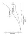
- FIG. 24illustrates attenuation versus frequency comparing the ideal feedthrough capacitor to one that has undesirable ground electrode plate connection to an oxidized surface
- FIG. 25is a perspective view of an exemplary feedthrough capacitor embodying the present invention.
- FIG. 26is a sectional view taken along line 26 - 26 of the structure of FIG. 25 ;
- FIG. 27is a perspective view of another exemplary feedthrough capacitor embodying the present invention.
- FIG. 27Ais an exploded view of the structure of FIG. 27 showing the peninsula portion of the ferrule
- FIG. 28is a sectional view taken along line 28 - 28 of the structure of FIG. 27 ;
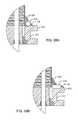
- FIG. 28Ais an enlarged view of a novel embodiment of a similar structure of FIG. 28 taken along lines 28 A- 28 A;
- FIG. 28Bis another embodiment of the structure of FIG. 28A now showing a rectangular shaped structure attached to the ferrule;
- FIG. 28Cis a view similar to 27 A except now showing a recess on the ferrule for the wire to fit within;
- FIG. 29is a perspective view of another exemplary feedthrough capacitor embodying the present invention.
- FIG. 30is a sectional view taken along line 30 - 30 of the structure of FIG. 29 ;
- FIG. 31is a perspective view of another exemplary feedthrough capacitor embodying the present invention.
- FIG. 32is a sectional view taken along line 32 - 32 of the structure of FIG. 31 ;
- FIG. 33is a perspective view of another exemplary feedthrough capacitor embodying the present invention.
- FIG. 34is a sectional view taken along line 34 - 34 of the structure of FIG. 33 ;
- FIG. 35is a perspective view of another exemplary feedthrough capacitor embodying the present invention.
- FIG. 36is an exploded view of the structure of FIG. 35 showing the peninsula portion of the ferrule
- FIG. 37is a sectional view taken along line 37 - 37 of the structure of FIG. 35 ;
- FIG. 38is a perspective view of another exemplary feedthrough capacitor embodying the present invention.
- FIG. 39is a sectional view taken along line 39 - 39 of the structure of FIG. 38 now showing a ground electrode plate;
- FIG. 40is an sectional view taken along line 40 - 40 of the structure of FIG. 38 now showing an active electrode plate
- FIG. 41is a perspective view of another exemplary feedthrough capacitor embodying the present invention.
- FIG. 42is an sectional view taken along line 42 - 42 of the structure of FIG. 41 now showing a ground electrode plate;
- FIG. 43is an sectional view taken along line 43 - 43 of the structure of FIG. 41 now showing an active electrode plate
- FIG. 44is a sectional view taken along lines 44 - 44 of the structures of both FIGS. 38 and 41 ;
- FIGS. 45A, 45B and 45Care perspective views of various embodiments of the novel ground attachments shown in FIGS. 38, 41 and 44 ;
- FIG. 46is a perspective view of another exemplary feedthrough capacitor embodying the present invention.
- FIG. 47is an exploded view of the structure of FIG. 46 showing the novel ground attachment below the capacitor;
- FIG. 48is a perspective view of another exemplary feedthrough embodying the present invention now showing novel rectangular ground attachments in the ferrule;
- FIG. 49is a perspective view of another exemplary feedthrough embodying the present invention now showing novel circular ground attachments in the ferrule;
- FIG. 50is similar to either FIG. 48 or 49 now showing the capacitor grounded to the ferrule
- FIG. 51is a sectional view taken along line 51 - 51 of the structure of FIG. 50 now showing a ground electrode plate;
- FIG. 52is a sectional view taken along line 52 - 52 of the structure of FIG. 50 now showing an active electrode plate;
- FIG. 53is a perspective view of another exemplary feedthrough embodying the present invention now showing novel ground attachments around the continuous perimeter of the ferrule;
- FIG. 54is an exploded view of another exemplary feedthrough capacitor embodying the present invention now showing novel ground attachment plate.
- FIG. 55is the perspective assembled view of the structure of FIG. 54 showing the capacitor metallization grounded to the novel plate.
- FIG. 1is a wire-formed diagram of a generic human body showing various types of active implantable and external medical devices 100 that are currently in use.
- 100 Ais a family of external and implantable hearing devices which can include the group of hearing aids, cochlear implants, piezoelectric sound bridge transducers and the like.
- 100 Bincludes an entire variety of neurostimulators and brain stimulators.
- Neurostimulatorsare used to stimulate the Vagus nerve, for example, to treat epilepsy, obesity and depression.
- Brain stimulatorsare similar to a pacemaker-like device and include electrodes implanted deep into the brain for example but not limited to sensing the onset of the seizure and also providing electrical stimulation to brain tissue to prevent the seizure from actually happening, or for treating memory loss, Alzheimer's and the like.
- 100 Cshows a cardiac pacemaker which is well-known in the art.
- 100 Dincludes the family of left ventricular assist devices (LVAD's), and artificial hearts, including the recently introduced artificial heart known as the ABIOCOR.
- 100 Eincludes an entire family of drug pumps which can be used for dispensing of insulin, chemotherapy drugs, pain medications and the like. Insulin pumps are evolving from passive devices to ones that have sensors and closed loop systems. That is, real time monitoring of blood sugar levels will occur. These devices tend to be more sensitive to EMI than passive pumps that have no sense circuitry or externally implanted lead wires.
- 100 Fincludes a variety of external or implantable bone growth stimulators for rapid healing of fractures.
- 100 Gincludes urinary incontinence devices.
- 100 Hincludes the family of pain relief spinal cord stimulators and anti-tremor stimulators.
- 100 Halso includes an entire family of other types of neurostimulators used to block pain.
- 100 Iincludes a family of implantable cardioverter defibrillators (ICD) devices and also includes the family of congestive heart failure devices (CHF). This is also known in the art as cardio resynchronization therapy devices, otherwise known as CRT devices.
- 100 Jillustrates an externally worn pack. This pack could be an external insulin pump, an external drug pump, an external neurostimulator, a Holter monitor with skin electrodes or even a ventricular assist device power pack.
- FIG. 2is an isometric cut-away view of a unipolar feedthrough capacitor 132 . It has an outside diameter metallization 142 and an inside diameter metallization 144 . Active electrode plates 148 and ground electrode plates 146 are interleaved in the dielectric body. The active electrode plate set 148 is connected to the inside diameter metallization 144 . The ground electrode plate set 146 is connected to the outside diameter metallization 142 .
- Metallization surfaces 142 and 144can be glass fritted platinum silver or various types of plating. The metallization surfaces 142 and 144 are very important as it is easy to make electrical connection to these surfaces to other circuit elements.
- FIG. 3is a cross-sectional view of the unipolar capacitor of FIG. 2 shown connected to the hermetic terminal of an active implantable medical device, such as a cardiac pacemaker. Shown is a hermetic seal formed from an insulator 160 , such as an alumina ceramic, glass or the like. A gold braze 162 forms a hermetic seal between the insulator 160 and leadwire 114 , 111 .
- the leadwire labeled 114 on the body fluid sideis generally directed to an implantable lead that has an electrode contactable to biological cells (not shown).
- a second gold braze 150which hermetically connects the outside diameter of the insulator material 160 to a ferrule 112 .
- the ferruleis generally of titanium.
- the AIMD housing 116is also generally of titanium.
- a laser weld 154is formed which connects the ferrule 112 to the AIMD housing 116 electrically and mechanically.
- the laser weld 154also forms a hermetic seal.
- the unipolar feedthrough capacitor 132 of FIG. 2is shown mounted directly to the hermetic seal insulator.
- An electrical connection 156connects the capacitor inside diameter metallization 144 to leadwire 111 .
- Oxides of titanium, for example, titanium dioxideis so stable, it's used as a paint pigment. It is also highly resistive and also has semi-conductive properties. For this reason, this inserts an undesirable series resistance R OXIDE between the feedthrough capacitor and the ferrule 112 and/or AIMD housing 116 .
- FIG. 4is a schematic diagram of unipolar feedthrough capacitor shown in FIGS. 2 and 3 . Shown is an ideal feedthrough capacitor C.
- feedthrough capacitorsare three-terminal devices in that there is an input side 114 (terminal one), an output side 111 (terminal two) and a ground 116 (terminal three).
- EMIelectromagnetic interference
- This EMI energymay be undesirably coupled along the implanted leadwire conductors to lead 111 , which is directed to sensitive AIMD electronics.
- EMIcan disrupt the proper operation of AIMD electronic circuitry.
- the feature in the feedthrough capacitor as illustrated in FIGS. 2 and 3is to divert incoming EMI energy in the implanted lead and dissipate it to the electromagnetically shielded housing 116 of the AIMD which said EMI energy may be dissipated as a harmless amount of thermal or RF energy.
- the capacitoris also known as a frequency variable impedance element.
- the capacitive reactance X c in ohms: X c1/[2 ⁇ fc] This inverse relationship with frequency means that, at very low frequencies, the capacitor looks like an open circuit (as if it were not there at all), and at very high frequencies, the capacitor acts as a short circuit where it diverts undesirable RF energy such as emissions from cellular telephones, microwave ovens or the like.
- R OXIDEThis resistive element is highly undesirable because it degrades the performance of the feedthrough capacitor all across its frequency range. There is also a great deal of variability in this oxide. During the gold brazing operation or during the formation of the hermetic seal, oxide poisoning may reach any corner or part of the brazing oven. The inventors have experienced some of the parts to be relatively oxide free where others in the lot may have a very thick or heavy oxide build-up.
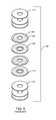
- FIG. 5is an exploded view of the cover sheets 147 and internal electrodes of the unipolar capacitor 132 previously described in FIGS. 2 and 3 .
- a number of blank cover sheets 147are placed on top and bottom for insulative and mechanical strength purposes.
- FIG. 6is a diagrammatic explosion of a typical AIMD, such as a cardiac pacemaker 100 C. It has an overall electromagnetic shielded titanium housing 116 along with a polymer header block (connector block) 101 . Shown, are two implantable leads 107 and 107 ′, which in this case are directed to chambers of the heart 124 . There are additional electrodes located at point 109 in the right ventricle and distal electrodes 109 ′ located in the right atrium. In the art, this is known as a simple dual chamber bipolar pacemaker. As shown, EMI can be undesirably coupled to leads 107 and 107 ′ where it can be conductive to the leadwires 114 of the hermetic seal assembly 120 .
- the feedthrough capacitor element 132diverts the EMI conducted on leads 114 into the conductive AIMD housing 116 where it is dissipated as eddy currents or RF energy (EMI′) as simply coupled to surrounding body tissues. In any event, the EMI is prevented from reaching the delicate AIMD circuit boards 122 .
- EMI′RF energy
- FIG. 7is an isometric view of the quad polar feedthrough capacitor 132 previously described in the prior art pacemaker of FIG. 6 .
- the quad polar feedthrough capacitorhas an outside diameter metallization 142 and four feedthrough holes all of which have inside diameter metallization 144 .
- FIG. 8is a sectional view taken from section 8 - 8 of FIG. 7 and illustrates the quad polar feedthrough capacitor interior electrode plates.
- FIG. 9is an exploded view of the quad polar feedthrough capacitor of FIG. 7 . Shown, are the four active electrode plate areas 148 and the ground electrode plates 146 . As previously described, these active and ground electrode plates are in interleaved relationship. There are also a number of blank ceramic cover sheets 147 added on top and bottom for mechanical strength and electrical insulation. Those skilled in the capacitor art will understand that a higher voltage capacitor could be built by interleaving additional blank electrodes between the active and ground electrode plates thereby building up the dielectric thickness. Typically, the dielectric material could be of barium titanate ceramic and could vary in dielectric constant k anywhere from 50 all the way up to several thousand.
- FIG. 10is the schematic diagram of the quad polar feedthrough capacitor of FIG. 7 .
- feedthrough capacitorsare three-terminal devices that have no series inductance or series resistance. This is why they make such effective broadband electromagnetic interference filters.
- a feedthrough capacitorcan provide attenuation over a very broad frequency range extending even to 18 to 20 GHz.
- this oxideis highly undesirable as it can seriously degrade filter performance.
- filter performanceis described by the terms insertion loss or by attenuation. Both of these are generally measured in a balanced 50 ohm system with the measurement units in decibels.
- FIG. 11illustrates a prior art quad polar feedthrough capacitor that, in this case, is rectangular instead of round. It still has an outside metallization 142 , but in this embodiment, instead of being all around a perimeter or outside diameter, it is shown only over a portion of the rectangular edge of the capacitor. This can actually be done in many ways. One way would be to extend the metallization 142 around the entire perimeter of the capacitor. Feedthrough metallization 144 is provided for each of the four feedthrough holes.
- FIG. 11 in combination with FIG. 12illustrates an exploded assembly view wherein the capacitor of FIG. 11 is designed to be mounted atop a prior art quad polar hermetic terminal of FIG. 12 . The hermetic terminal of FIG.
- the 12has four leadwires 111 , 114 , a hermetic insulator 124 and a ferrule, generally of titanium 112 .
- a gold braze 150which forms a hermetic joint between the ferrule 112 and the generally alumina ceramic insulator 124 .
- There are four more gold brazes 162which join leadwire 111 to the inside diameter holes of the hermetic insulator 124 .
- FIG. 13is taken from section 13 - 13 from FIG. 11 . Shown are the four active electrode plates 148 of the feedthrough capacitor.
- FIG. 14is taken from section 14 - 14 from FIG. 11 and illustrates the ground electrode plate 146 of the feedthrough capacitor.
- FIG. 15is an assembly view taken from FIGS. 11 and 12 showing the quad polar rectangular feedthrough capacitor mounted onto the hermetic seal housing and the ferrule 112 .
- An electrical connection 152is generally made with a thermal-setting conductive adhesive between the capacitor metallization 142 directly to the ferrule 112 .
- FIG. 16is a sectional view taken from section 16 - 16 from FIG. 15 .
- This sectional viewgoes through one of the leadwires 111 and shows the interior ground electrode plate set 146 and the active electrode plate set 148 .
- the ground electrode plates 146make electrical and mechanical contact to the capacitor ground metallization 142 .
- thermal-setting conductive adhesive 152always contains a certain amount of available oxygen.
- a laser weldis formed to the AIMD housing, which is positioned to be placed in slot 163 , this significantly raises the temperature of thermal-setting conductive adhesive 152 .
- a thermal-setting conductive polyimideis the connection material of choice, as a conductive polyimide is stable at temperatures well above 300 degrees C. This is in comparison to most epoxies which are only rated to about 230 degrees C.
- oxygencan be released from a thermal-setting conductive material 152 and then be formed as a titanium dioxide or trioxide 164 on the ferrule 112 of the hermetic seal.
- FIG. 17is the schematic diagram of the quad polar feedthrough capacitors previously illustrated in FIGS. 11, 15 and 16 . Shown, is the undesirable R OXIDE which is shown in series between the ideal feedthrough capacitor and ground, which is the same electrical potential as the AIMD housing 116 . As will be shown, the presence of this resistive oxide seriously degrades the filter performance.
- FIG. 18is taken from FIG. 20 of U.S. Pat. No. 6,765,779 which describes gold bond pads to eliminate the problem of attachment to oxides of titanium between the feedthrough capacitor outside diameter and its ground electrode plate sets. Referring to FIG. 18 , one can see that there are novel gold braze pads 165 that have been added. Referring to FIG. 12 , one can see that these gold braze pads 165 are not present.
- FIG. 19shows that the electrical connections 152 between the capacitor's ground metallization 142 is now directly made to this non-oxidizable noble pad.
- U.S. Pat. No. 6,765,779is incorporated herein by reference.
- a preferred material for the oxide resistant pad 165is gold.
- this gold pad 165is continuous and is co-formed at the same time the hermetic seal (gold braze) is made to the alumina ceramic insulator 160 .
- thisis a limitation of U.S. Pat. No. 6,765,779 in that the gold bond pad 165 is always formed as part of the co-braze to the alumina ceramic insulator 160 .
- FIG. 20is generally taken from section 20 - 20 from FIG. 19 . It is very similar to FIG. 16 except that the gold braze area 165 has been enlarged to include the gold bond pad area 165 .
- Pure goldhas a high melting point (1064° C.) which is above the allotropic transformation temperature of titanium (883° C.). Titanium is soluble in gold, particularly more so at elevated temperature. Elevated temperature maximizes titanium dissolution into gold. As previously noted, titanium is highly reactive to air readily forming surface oxides. Brazing to titanium, therefore, is generally performed at high vacuum.
- a gold brazed joint 164 165is formed between, for example, a gold braze preform and a titanium ferrule
- the titaniumreacts with the gold to form a direct metallurgical bond to the titanium ferrule 112 .
- this direct metallurgical bondis gold-rich, it essentially retains the high conductivity of the gold and its oxide resistant properties.
- the enlarged gold braze area surfacethat is, the bonding pad that is formed is part of the oxide-resistant metallurgical bond.
- This enlarged gold braze areaserves as the, electrical connection material that is connectable to the capacitor ground metallization 142 .
- a continuous electrical connectionthat is consistent in its conductivity over the service life of the device is made. The electrical connection is between the titanium ferrule 112 and the filter capacitor ground metallization 142 via the electrical connection material 152 directly to the non-oxidizable gold bond pad 165 .
- FIG. 21is very similar to FIG. 19 , except in this case, the quad polar capacitor is round which is consistent with the feedthrough capacitor 132 previously illustrated in the cardiac pacemaker of FIG. 6 .
- FIG. 22is generally taken from section 22 - 22 from FIG. 21 and illustrates the capacitor's internal structure including its ground and active electrode plates.
- outside diameter electrical connection material 152which connects the outside diameter metallization 142 to the ferrule 112 , is directly attached to the gold braze material 165 .
- the fact that some of this overlaps onto the titanium surfaceis not important. What is critical is that a suitable amount of the electrical connection material 152 is directly attached to an oxide resistant noble surface, such that an undesirable resistance can never develop.
- FIG. 23illustrates the schematic diagram of the improved rectangular quad polar feedthrough capacitor of FIG. 19 and the round quad polar capacitor of FIG. 21 .
- ground 116is the overall shielded equipotential surface of the electromagnetically shielded housing 116 .
- FIG. 24is attenuation versus frequency curves which compares the ideal feedthrough capacitor to one that has undesirable ground electrode plate connection to an oxidized surface.
- the feedthrough capacitor with the resistive oxide R OXIDEhas greatly reduced attenuation all across the frequency band as compared to the ideal feedthrough capacitor.
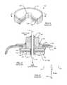
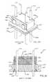
- FIG. 25illustrates a filtered feedthrough assembly of the present invention 210 .
- Illustratedis a ferrule 216 of the hermetic seal.
- the ferruleis generally of titanium. In this case, it has a continuous slot 217 , which can receive the can halves of an active implantable medical device, such as a cardiac pacemaker. These titanium can halves are then laser welded to the titanium ferrule 216 .
- a feedthrough capacitor 212would be oriented towards the inside of the can to protect it from body fluids.
- there are novel round platinum iridium wires 218which have been laser welded 220 directly to the ferrule 216 .
- Laser weld 220could also be replaced by a resistance weld or a secondary braze operation at a lower temperature using for example, but not limited to, copper based brazing materials such as Cu—SiI or Ti—Cu—SiI, silver based brazing materials such as SiIvaloy (Ag—Cu—Zn) or Gapasil (Ag—Pd—Ga), gold based brazing materials such as Au—Cu, Au—Cu—Ag, or Au—Cu—Ni, or palladium based braze materials such as Pd—Ni—Si.
- a capacitor ground metallization 223is attached using solder or thermal-setting conductive adhesives 222 to the platinum iridium wire 218 .
- the platinum iridium wirecan actually be of any noble material including platinum, gold and its alloys, palladium and its alloys, silver and its alloys and combinations thereof.
- Leadwires 214 through 214 ′′′pass through the feedthrough capacitor and through the hermetic seal. This is best understood by referring to FIG. 26 , which is taken from section 26 - 26 from the structure of FIG. 25 .
- FIG. 26illustrates the laser weld 220 , the noble wire 218 and the solder or thermal-setting conductive adhesive 222 .
- a ground electrode plate stack 230 and an active electrode plate stackare designated by 232 ′ and 232 ′′′ which are connected respectively to terminal pins 214 ′ and 214 ′′′.
- the preformed capacitor feedthrough hole, inside diameter metallization of the capacitor feedthrough hole and electrical connection materialhas been omitted for clarity. It is understood by one skilled in the art that various structures and techniques are used to connect the active electrode plates to the lead wires. In this case, the active electrodes 232 are shown directly contacting the lead 214 ′.
- Gold braze 226connects the ferrule 216 to the alumina insulator 224 providing a robust mechanical and hermetically sealed joint.
- Gold braze 228forms a robust mechanical and hermetic seal between the alumina ceramic 224 and the leads 214 .
- the leadwire 218provides a very novel feature, that is, electrical connection material 222 does not directly attach to the ferrule 216 .
- the ferruleis typically of titanium, which commonly forms titanium oxides. Titanium oxides are very resistive and can also act as semiconductors. This means that a direct connection to titanium would degrade the effectiveness of the capacitor ground electrode plate stack.
- the noble wire 218acts as an intermediate surface. By laser welding it to the titanium ferrule 216 , one forms a very strong oxide resistant metallurgical bond.
- the surface on wire 218is relatively oxide free. For example, it could be gold, platinum or the like which are oxide resistant at room temperatures. In fact, it would be preferable if the wire 218 be pure platinum and not platinum iridium. The reason for this is that the iridium can form oxides.
- the gold brazes forming the hermetic seals 226 and 228are on the body fluid side.
- AIMD manufacturersthat prefer having the gold braze on the body fluid side.
- making a connection to the capacitor's outside perimeter or diameter metallization 223 to the same gold braze surfacebecomes impossible.
- there is no possibility to provide the gold bond pad 165which is a contiguous part of the hermetic seal braze 226 .
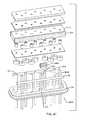
- FIGS. 27-28are similar to FIGS. 25-26 but now show a peninsula structure 244 formed as part of the ferrule 216 .
- a ground wire 242is attached to the peninsula 244 .
- the ground wire 242is not connected to the ground electrode plates 230 .
- the ground electrode platesare still electrically coupled to the metallization 223 which is then electrically coupled to the ferrule 216 through the weld 220 , the wire 218 and the thermosetting conductive adhesive 222 or solder.
- the grounded peninsula 244which is a continuous part of the machined ferrule 216 , is electrically attached via material 219 to the grounded pin 242 .
- the ground materialcould be a laser weld, a gold braze, a solder, a thermal-setting conductive adhesive or the like.
- pin 242is provided as a convenience to the AIMD manufacturer to either ground the internal circuit board, or to provide an addition pacing vector to a conductor of an implanted lead (not shown) or both.
- the electrical ground attachment from the peninsula 244 to lead 242is very low in resistivity, meaning that it would also be applicable for high voltage implantable cardioverter defibrillator applications. In such an application, a very light shock current would flow through this ground joint to an external electrode (not shown).
- FIG. 28Ais an enlarged view of a new embodiment of the structure from FIG. 28 taken from lines 28 A- 28 A now showing the wire 218 recessed into the ferrule 216 .
- the wire 218may be positioned and affixed in a more efficient manner.
- FIG. 28Bis an enlarged view of another embodiment of the structure from FIG. 28 taken from lines 28 B- 28 B now showing the rectangular wire 218 recessed into the ferrule 216 .
- the rectangular wire 218may be positioned and affixed in a more efficient manner.
- FIG. 28Cshows a perspective view similar to FIG. 27A now with the recess 231 and inserts 233 clearly shown.
- the inserts 233are placed in the recess 231 before the wire 218 is placed and may be gold metal, gold brazed or any of the material variations and connection methods already described herein.
- FIG. 29is similar to FIG. 25 and illustrates that the two wires 218 could be replaced by a number of pads 234 as shown.
- the padscould be formed as a continuous part (not shown) of the machining of the ferrule 216 or they could be added as a subsequent assembly by gold brazing or laser welding 220 as shown.
- the pads 234would be of the same noble materials previously described as for the wire 218 . This means that a convenient oxide resistant electrical connection 222 could be made using solder or thermal-setting conductive adhesives.
- the intermediate biostable and oxide resistant intermediate structuresuch as lead 218 shown in FIG. 27 with pad 234 as illustrated in FIG. 29 , must have the following properties: 1) they must be weldable or brazable to the titanium ferrule 216 ; 2) this weld or braze joint must break through any oxides of titanium and form a metallurgical bond between the structure 218 or 220 and the ferrule 216 ; and 3) the intermediate biostable wire of pad 234 must be connectable to the capacitor's external metallization 223 .
- the number of connection methods to the capacitor's external metallizationis limited. This includes solders, solder paste and all types of thermal-setting inductive adhesives.
- the biostable wire 218 or pad 234need not be platinum, but it can consist of a long list of metals that would meet the above criteria. Obvious choices would be gold, palladium, tantalum, and niobium. Additional non-limiting considerations include: tungsten, iridium, ruthenium, rhodium, silver, osmium, or combinations thereof.
- platinum based materialssuch as platinum-rhodium, platinum-iridium, platinum-palladium, or platinum-gold, and naturally occurring alloys like platiniridium (platinum-iridium), iridiosmium and osmiridium (iridium-osmium).
- FIG. 30is a sectional view taken from section 30 - 30 from FIG. 29 illustrating that the pads 234 and 234 ′ are disposed on both sides of the capacitor. It will be obvious to those skilled in the art that they could also be disposed at the ends of the capacitor (not shown). It will be appreciated to one skilled in the art that the pads could be connected. For example, referring once again to FIG. 27 , pads 234 and 234 a could be filled in between so that there was one large continuous pad. These pads could also have holes in them to further facilitate the electrical attachment between the pad and the capacitor external ground metallization 223 .
- FIG. 31is a perspective view of another embodiment similar to FIGS. 25-30 now showing a different configuration of pad 234 .
- pad 234is shown in an L-shape. There is a hole in the bottom of the pad facilitating the laser weld or braze 220 to the ferrule 216 .
- FIG. 32is a sectional view taken along line 32 - 32 from the structure of FIG. 31 .
- FIG. 33is a perspective view of yet another embodiment of a feedthrough capacitor assembly 210 similar to FIGS. 25-32 .
- the pad 234is a long pad that spans the length of the long side of the capacitor 212 .
- the pad 234has a large hole to facilitate the placement and bonding of the conductive adhesive 222 .
- FIG. 34is a sectional view taken from lines 34 - 34 from the structure of FIG. 33 .
- FIG. 34is a sectional view taken from section 34 - 34 from FIG. 33 . It shows the long bracket 234 cross-section along with laser weld 222 .
- FIG. 35is similar to FIG. 25 except in this case there are more terminal pins 214 . Accordingly, it is necessary that the oxide-free biostable wire 220 be longer and have more laser welds 222 . This is because it would be undesirable to have a long distance between a filtered terminal pin and its associated ground. This is because inductance and resistance can build up across an internal ground plane, thereby degrading the RF filtered performance of a distal filtered pin.
- FIG. 36is an exploded view of the structure of FIG. 35 . In FIG. 36 , the ground pin 242 is shown laser welded or gold brazed into the ferrule 216 in the peninsula area 244 .
- the capacitoris a conventional capacitor wherein the ground electrode plates are terminated 223 with metallization disposed along the two long outside ends of the capacitor 212 .
- a capacitor's ground electrode platescould be connected to this grounded pin as completely described in U.S. Pat. No. 6,765,779, the contents of which are incorporated herein by reference.
- FIGS. 35-37an alternative is given wherein a direct connection to terminal pin 242 and the grounding of the capacitor's electrode stacks 230 is nonexistent. That is, the electrical connection is between the capacitor metallization 223 and the noble wires 218 .
- FIG. 37is a sectional view taken from section 37 - 37 from FIG. 35 illustrating that any one of the active pins 214 passes through feedthrough holes near the center of the capacitor 212 in a staggered pattern where the pin 214 makes contact with its own individual set of active electrode plates (not shown) or many active electrode plates.
- the ground electrode platescontact the capacitor's long-side perimeter metallization 223 and then electrical attachment material, which can be solder or thermal-setting conductive adhesive, attaches the capacitor ground metallization 223 to the noble wire 218 .
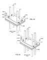
- FIG. 38is similar to FIG. 35 , which illustrates an alternative method of grounding the capacitor's ground electrode stack 230 .
- FIG. 36illustrates an alternative method of grounding the capacitor's ground electrode stack 230 .
- ground pin 242is electrically and mechanically attached.
- FIG. 28ground pin 242 is electrically attached to the ferrule 216 and is thereby grounded in a similar manner as shown in FIG. 36 .
- a novel L-shaped clip 246 ′is electrically attached to ground pin 242 and engages a portion of the capacitor's external ground metallization 223 . This is best illustrated in FIG. 28 , where the ground clip 246 ′ being electrically connected 222 to the capacitor's ground metallization 223 is shown.
- clip 246 ′disposed on the top surface of the capacitor 212 .
- an insulating structure 252that is disposed on top of capacitor 212 .
- Thiscan be a conformal coating of insulation, an insulation sheet with adhesive layer, or even an alumina ceramic thin sheet of insulation.
- this insulation sheet 252is alumina ceramic, it may have a cut-out pocket so that the clip 246 ′ drops down into it and fits flush with the top of the insulating layer 252 . This would help to hold the clip 246 ′ in place and to index it.
- FIG. 39shows the ground electrode plate 230 which does not make contact with the leadwires 214 or the grounded wire 242 .
- the ground electrode plate 230makes contact with metallization 223 which is then in electrical contact with novel pad 246 ′.
- FIG. 40shows a multitude of active electrode plates 232 electrically coupled to the leadwires 214 . Note that the grounded pin 242 lacks an active electrode plate 232 .
- FIGS. 41-43are very similar to FIGS. 28-30 .
- FIGS. 41-43show a different embodiment of the novel pad 246 a.
- Pad 246 ais longer along the length of increased metallization 223 . This design would increase filter performance due to the shortened electrical pathways. In this way, the inductance across the ground planes of the capacitor is greatly reduced. This means that outer pins 214 will have improved attenuation and greater insertion loss than the structure previously illustrated in FIG. 38 .
- FIG. 44is a sectional view for both FIGS. 38 and 41 .
- novel pad 246could also extend over the opposite side metallization and also make electrical contact. This would further improve filter performance by lowering electrical pathway lengths.
- FIGS. 45A, 45B and 45Cillustrate various types of L-shaped clips 246 .
- electrical connection material 222which can be a solder or a thermal-setting conductive adhesive, to be placed on the outside of the clip and also inside the elliptical hole. This increases the electrical contact area and thereby reduces the resistance as well as improves mechanical strength.
- FIGS. 46 and 47are an alternative embodiment of clip 246 b previously illustrated in FIGS. 38 and 41 .
- the novel clip 246 bis under the capacitor 212 sandwiched between the ferrule 216 and the capacitor 212 .
- a holeis also in the clip 246 b to facilitate placement of conductive adhesive 222 .
- FIG. 47is an exploded view that best shows the shape of novel clip 246 b.
- the clip 246is disposed underneath the capacitor 212 and electrically and mechanically attached directly to the peninsula structure. Having the clip 246 ′ disposed underneath the capacitor 212 , and then coming up on the side as is illustrated, would improve the RF performance of the capacitor. Effectively, this would shorten the ground pin 242 to almost zero thereby reducing the impedance and inductance of the ground clip 246 ′.
- a notch(not shown) could be put in the ferrule 216 of the hermetic terminal to facilitate the clip coming out through the bottom so that the capacitor 212 still would sit flush on top of the ferrule structure 216 .
- FIGS. 48-53are similar to FIGS. 25-34 except that in this case pockets 248 and noble metal inserts 250 have been formed so that an oxide resistant electrical attachment 222 can be made between the capacitor ground metallization 223 and the ferrule 216 .
- An alternative embodiment 250 ′is shown where first, a brazing perform, such as a gold braze perform 250 a, is placed and then a platinum cap 250 b is placed over it. Alternative metals may be used as noted earlier.
- a braze 250 aone could use a resistance weld or lower temperature brazes such as those listed previously with the Cu—SiI or Ti—Cu—SiI examples.
- Platinum pad 250 bwould be slightly longer in the length direction and slightly longer in the width direction than the underlying pre-form 150 A. This overlaying would prevent it from reflowing and leaking out during a gold braze operation. In addition, the pad 250 b would protrude above the surface of the ferrule. This turns out to be very convenient during electrical attachment of the feedthrough capacitor (not shown) outside perimeter metallization 223 . In other words, the protruding pad 250 b would provide a convenient stop for a solder paste, a solder pre-form or a thermal-setting conductive adhesive (dispensed by robot). This is best understood by referring to FIGS.
- FIG. 48 and 49which shows that a pocket 248 and 248 a are first formed at the time of manufacturing the ferrule 216 of the hermetic seal subassembly 210 .
- These pocketscan be rectangular (as shown), can be rectangular with rounded ends or it can be round holes as illustrated as 248 a or even a continuous groove or slot as illustrated in FIG. 53 as 248 c.
- a noble wire 218as previously described in FIG. 25
- a material 250such as CuSiI or TiCuSiI, gold or any other material as disclosed earlier that can form a metallurgically sound bond to titanium while at the same time, providing an oxide resistant surface to which electrical attachment 222 can form a solid bond.
- a circular gold braze pre-form 250 Abcould first be placed into the counter-bore hole 248 a and then a platinum or equivalent cap 250 Aa could be placed over it. These could all be reflowed into place leaving a convenient area to make electrical attachment between the capacitor external ground metallization 223 , through the oxide resistant pad 250 Aa, through the braze material 250 Ab and, in turn, to the ferrule 216 .
- FIG. 50is an isometric view of the quad polar feedthrough capacitor 212 shown mounted to the hermetically sealed ferrule assembly previously illustrated in FIG. 48 . Shown is an electrical attachment material 222 between the capacitor ground metallization 223 that connects to the oxide resistant connection pads 250 , 250 ′. Referring once again to FIG. 50 , one can see that there is metallization 223 on both short ends of the capacitor 212 . This metallization 223 could extend along the long sides or, alternatively, along all perimeter sides of the capacitor. In the case where the length of the perimeter metallization 223 is made longer, then additional pockets and oxide resistant pads 250 would be required.
- FIGS. 51 and 52illustrate the ground and active electrode plate sets of the capacitor 212 previously illustrated in FIG. 50 .
- FIG. 51shown is that the ground electrode plate 230 does not make contact with any of the terminal pins 214 .
- the metallization 223contacts the ground electrode plate set 230 on its left and right ends.
- FIG. 52illustrates the active electrode plates 232 . In this case, the active electrode plates 232 are connected to each one of the feedthrough terminal pins 214 .
- FIG. 53is the same ferrule as previously described in FIGS. 49 and 50 except that instead of a discrete number of machined pads 248 , there is a continuous groove 248 c formed around the entire perimeter of the capacitor. This would be filled with a gold braze, Cu—SiI or Ti—Cu—SiI or other material previously listed to form an oxide resistant connection area for the feedthrough capacitor (not shown).
- a feedthrough capacitor 212in this case, would have perimeter metallization 223 along all four of its perimeter sides and either a continuous or a multiplicity of short electrical connections 222 would be made between the capacitor metallization 223 and the gold braze or equivalent material that has been flowed in the trough 248 c (not shown).
- FIGS. 54 and 55are yet another embodiment of the present invention.
- gold films 250 bmay be placed on top of the ferrule 216 .
- a conductive sheet 254is laid overtop the gold films 250 b.
- the capacitor 212can be placed overtop the conductive sheet 254 and then an electrical connection using conductive adhesives 222 can be made between the external metallization 223 and the conductive sheet 254 .
- the metallizationis around the entirety of the capacitor 212 . This design would also reduce both the inductance and equivalent series resistance of the capacitor 212 .
Landscapes
- Engineering & Computer Science (AREA)
- Power Engineering (AREA)
- Microelectronics & Electronic Packaging (AREA)
- Manufacturing & Machinery (AREA)
- Health & Medical Sciences (AREA)
- Nuclear Medicine, Radiotherapy & Molecular Imaging (AREA)
- Biomedical Technology (AREA)
- Radiology & Medical Imaging (AREA)
- Life Sciences & Earth Sciences (AREA)
- Animal Behavior & Ethology (AREA)
- General Health & Medical Sciences (AREA)
- Public Health (AREA)
- Veterinary Medicine (AREA)
- Electrotherapy Devices (AREA)
Abstract
Description
This application claims priority to U.S. provisional application Ser. No. 61/841,419, filed on Jun. 30, 2013. The present application also claims priority to and is a continuation-in-part application of U.S. application Ser. No. 13/873,832, filed on Apr. 30, 2013, the contents of which are incorporated herein by reference. The present application also claims priority to and is a continuation-in-part application of U.S. patent application Ser. No. 13/743,276, filed on Jan. 16, 2013, the contents of which are incorporated herein by reference.
The present invention generally relates to feedthrough capacitors. More particularly, the present invention relates to a feedthrough capacitor located on the device side with a low impedance and oxide-resistance electrical connection.
Feedthrough capacitors and MLCC chip capacitors are well known in the prior art for active implantable medical devices (AIMDs). One is directed to U.S. Pat. Nos. 5,333,095; 5,905,627; 6,275,369; 6,529,103; and 6,765,780 all of which are incorporated herein by reference. The hermetic seal feedthrough terminal assemblies generally consist of a titanium ferrule into which an alumina hermetic seal is gold brazed. One or more lead wires penetrate through the alumina in non-conductive relationship with the ferrule. Gold brazes are also used to form a hermetic terminal between the one or more leadwires and the alumina ceramic.
First, some general information concerning good engineering design practice for electromagnetic interference (EMI) filters. It is very important to intercept the EMI at the point of lead conductor ingress and egress to the AIMD. It would be an inferior practice to put filtering elements down in the circuit board as this would draw EMI energy inside of the AIMD housing where it could re-radiate or cross-couple to sensitive AIMD circuits. A superior approach is to mount one or more feedthrough or MLCC-type capacitors right at the point of leadwire entrance so that it can be coupled to high frequency EMI signals from the lead conductors directly to the AIMD housing, which acts as an energy dissipating surface.
There are some interesting design challenges however. The titanium ferrule, which is laser welded into the overall AIMD housing, is at ground potential. Titanium tends to form oxides which act as either insulators or semi-conductors. Accordingly, grounding the feedthrough capacitor electrode plates directly to the titanium ferrule is contra-indicated. Reference is made to U.S. Pat. No. 6,465,779 (which is incorporated with this reference) which describes gold bond pad areas where the feedthrough capacitor external metallization can be directly connected to gold. The gold to which the feedthrough capacitor is directly connected is the braze material used to form the hermetic seal between the alumina and the titanium ferrule. As noted above, the hermetic seal is formed via a brazing process. By attaching the capacitor's ground plates to the gold, one can be assured that there will be no oxide that will increase the capacitor's equivalent series resistance (ESR) which can seriously degrade the capacitor's performance at high frequency. An undesirable aspect of using the gold braze for attachment is that gold is very expensive. Accordingly, there is a need for methods that provide a reliable low impedance ground path which are oxide resistant for grounding of AIMD filter capacitors. The present invention fulfills these needs and provides other related advantages.
An exemplary embodiment of a hermetically sealed filtered feedthrough assembly for an implantable medical device includes an insulator hermetically sealed to a conductive ferrule or housing. A conductor is hermetically sealed and disposed through the insulator in non-conductive relation to the conductive ferrule or housing between a body fluid side and a device side. A feedthrough capacitor is disposed on the device side. The feedthrough capacitor includes a first and a second end metallization, wherein the first end metallization is connected to at least one active electrode plate and wherein the second end metallization is connected to at least one ground electrode plate. The at least one active electrode plate is interleaved and disposed parallel to the at least one ground electrode plate, wherein the at least one active and at least one ground electrode plates are disposed within a capacitor dielectric. A first low impedance electrical connection is between the first end metallization and the conductor. A second low impedance electrical connection is between the second end metallization and the ferrule or housing. The second low impedance electrical connection includes an oxide-resistant metal addition attached directly to the ferrule or housing and an electrical connection coupling the second end metallization electrically and physically directly to the oxide-resistant metal addition.
In other exemplary embodiments the oxide-resistant metal addition may include a different material as compared to the ferrule or housing. The oxide-resistant metal addition may include a noble metal such as gold, platinum, palladium, silver and combinations thereof. The oxide-resistant metal addition may be laser welded to the ferrule or housing. The oxide-resistant metal addition may include a brazed metal such as gold. Possible braze materials include gold, gold-based metal, platinum, platinum based metal, palladium, palladium based metal, silver and silver based metal. Non-limiting noble metal based braze examples are gold-palladium, gold-boron, and palladium-silver. It is anticipated that proprietary brazes such as but not limited to the Pallabraze product family (palladium-containing) and Orobraze product family (gold-containing) offered by Johnson Matthey may be used. The braze material may be a rod, a ribbon, a powder, a paste, a cream, a wire and a preform such as but not limited to stamped washers.
A grounding loop may be defined on the device side having the first low impedance electrical connection and the second low impedance connection from the conductor through the feedthrough capacitor to the ferrule or housing. The total resistance of the grounding loop may be less than 1 milliohm. The total inductance of the grounding loop may be less than 10 nanohenries or less than 1 nanohenry.
The conductor may include a leadwire having platinum, palladium, silver or gold.
The insulator may be flush with the ferrule or housing on the device side. The insulator may include an alumina substrate comprised of at least 96% alumina and the conductor having a substantially closed pore and substantially pure platinum fill disposed within a via hole and extending between the body fluid side and the device side of the alumina substrate.
A hermetic seal may be between the platinum fill and the alumina substrate, wherein the platinum fill forms a tortuous and mutually conformal knitline or interface between the alumina substrate and the platinum fill, wherein the hermetic seal has a leak rate that is no greater than 1×10⁻⁷std cc He/sec.
An inherent shrink rate during a heat treatment of the alumina dielectric substrate in a green state may be greater than that of the platinum fill in the green state.
The oxide-resistant metal addition may include a wire, a pad, an L-shaped pad or an L-shaped pad with cutouts or combinations thereof.
A ground wire may be disposed through both the insulator and the feedthrough capacitor, where the ground wire is not electrically coupled to the at least one active and one ground electrode plate.
The ferrule or housing may include an integrally formed conductive peninsula, where the ground wire is electrically coupled to the peninsula.
The feedthrough capacitor may have a resonant frequency above 400 MHz. The feedthrough capacitor may have a capacitance of between 300 picofarads and 10,000 picofarads.
Other features and advantages of the present invention will become apparent from the following more detailed description, when taken in conjunction with the accompanying drawings, which illustrate, by way of example, the principles of the invention.
The accompanying drawings illustrate the invention. In such drawings:
Xc=1/[2πfc]
This inverse relationship with frequency means that, at very low frequencies, the capacitor looks like an open circuit (as if it were not there at all), and at very high frequencies, the capacitor acts as a short circuit where it diverts undesirable RF energy such as emissions from cellular telephones, microwave ovens or the like.
Referring once again toFIG. 4 , one can see ROXIDE. This resistive element is highly undesirable because it degrades the performance of the feedthrough capacitor all across its frequency range. There is also a great deal of variability in this oxide. During the gold brazing operation or during the formation of the hermetic seal, oxide poisoning may reach any corner or part of the brazing oven. The inventors have experienced some of the parts to be relatively oxide free where others in the lot may have a very thick or heavy oxide build-up.
Referring once again toFIGS. 25 and 26 , one can see that theleadwire 218 provides a very novel feature, that is,electrical connection material 222 does not directly attach to theferrule 216. The reason for this is that the ferrule is typically of titanium, which commonly forms titanium oxides. Titanium oxides are very resistive and can also act as semiconductors. This means that a direct connection to titanium would degrade the effectiveness of the capacitor ground electrode plate stack. Thenoble wire 218 acts as an intermediate surface. By laser welding it to thetitanium ferrule 216, one forms a very strong oxide resistant metallurgical bond. Now, the surface onwire 218 is relatively oxide free. For example, it could be gold, platinum or the like which are oxide resistant at room temperatures. In fact, it would be preferable if thewire 218 be pure platinum and not platinum iridium. The reason for this is that the iridium can form oxides.
Referring once again toFIG. 26 , shown is that the gold brazes forming thehermetic seals diameter metallization 223 to the same gold braze surface becomes impossible. In other words, as previously described inFIG. 18 , there is no possibility to provide thegold bond pad 165, which is a contiguous part of thehermetic seal braze 226. This is major driving feature of the present invention in that a methodology is provided so that the feedthrough capacitor can be properly grounded to an oxide resistant surface even when the gold brazes are disposed on the opposite side (the body fluid side).
Referring once again toFIG. 27A , one can see that the groundedpeninsula 244, which is a continuous part of the machinedferrule 216, is electrically attached viamaterial 219 to the groundedpin 242. The ground material could be a laser weld, a gold braze, a solder, a thermal-setting conductive adhesive or the like. In general,pin 242 is provided as a convenience to the AIMD manufacturer to either ground the internal circuit board, or to provide an addition pacing vector to a conductor of an implanted lead (not shown) or both. The electrical ground attachment from thepeninsula 244 to lead242 is very low in resistivity, meaning that it would also be applicable for high voltage implantable cardioverter defibrillator applications. In such an application, a very light shock current would flow through this ground joint to an external electrode (not shown).
Throughout the invention, the intermediate biostable and oxide resistant intermediate structure, such aslead 218 shown inFIG. 27 withpad 234 as illustrated inFIG. 29 , must have the following properties: 1) they must be weldable or brazable to thetitanium ferrule 216; 2) this weld or braze joint must break through any oxides of titanium and form a metallurgical bond between thestructure ferrule 216; and 3) the intermediate biostable wire ofpad 234 must be connectable to the capacitor'sexternal metallization 223. The number of connection methods to the capacitor's external metallization is limited. This includes solders, solder paste and all types of thermal-setting inductive adhesives. In general, although possible, it is not reliably possible to braze or weld directly to the capacitor'sexternal metallization 223, hence this option is not a preferred embodiment. In summary, thebiostable wire 218 or pad234 need not be platinum, but it can consist of a long list of metals that would meet the above criteria. Obvious choices would be gold, palladium, tantalum, and niobium. Additional non-limiting considerations include: tungsten, iridium, ruthenium, rhodium, silver, osmium, or combinations thereof. Other nonlimiting examples include platinum based materials such as platinum-rhodium, platinum-iridium, platinum-palladium, or platinum-gold, and naturally occurring alloys like platiniridium (platinum-iridium), iridiosmium and osmiridium (iridium-osmium).
Referring back toFIG. 38 , illustrated isclip 246′ disposed on the top surface of thecapacitor 212. There is an insulatingstructure 252 that is disposed on top ofcapacitor 212. This can be a conformal coating of insulation, an insulation sheet with adhesive layer, or even an alumina ceramic thin sheet of insulation. For the case where thisinsulation sheet 252 is alumina ceramic, it may have a cut-out pocket so that theclip 246′ drops down into it and fits flush with the top of the insulatinglayer 252. This would help to hold theclip 246′ in place and to index it.
In the alternative embodiment shown inFIG. 46 , theclip 246 is disposed underneath thecapacitor 212 and electrically and mechanically attached directly to the peninsula structure. Having theclip 246′ disposed underneath thecapacitor 212, and then coming up on the side as is illustrated, would improve the RF performance of the capacitor. Effectively, this would shorten theground pin 242 to almost zero thereby reducing the impedance and inductance of theground clip 246′. A notch (not shown) could be put in theferrule 216 of the hermetic terminal to facilitate the clip coming out through the bottom so that thecapacitor 212 still would sit flush on top of theferrule structure 216.
Referring once again toFIG. 49 , one can see that there is an alternative arrangement similar to that previously described inFIG. 48 . In this case, a circular gold braze pre-form250Ab could first be placed into thecounter-bore hole 248a and then a platinum or equivalent cap250Aa could be placed over it. These could all be reflowed into place leaving a convenient area to make electrical attachment between the capacitorexternal ground metallization 223, through the oxide resistant pad250Aa, through the braze material250Ab and, in turn, to theferrule 216.
Although several embodiments have been described in detail for purposes of illustration, various modifications may be made to each without departing from the scope and spirit of the invention. Various features of one embodiment may be incorporated into another embodiment, as each embodiment is not exclusive of the other features taught and shown herein. Accordingly, the invention is not to be limited, except as by the appended claims.
Claims (33)
1. A hermetically sealed filtered feedthrough assembly for an implantable medical device, the filtered feedthrough assembly comprising:
a) an insulator of electrically non-conductive material, the insulator comprising an outer insulator outer surface extending longitudinally from a first an insulator first end to a second an insulator second end, wherein the insulator has at least one conductor bore extending there through to the first and second insulator first and second ends;
b) a ferrule of an electrically conductive material, the ferrule comprising a ferrule sidewall defining a ferrule opening, wherein the insulator is hermetically sealed to the conductive ferrule sidewall in the ferrule opening;
c) a conductor comprising an electrically conductive material extending from a first conductor first end to a second conductor second end, wherein the conductor is hermetically sealed and disposed through the at least one conductor bore in the insulator and in a non-conductive relation with the conductive ferrule;
d) a filter capacitor, comprising:
i) a dielectric comprising an outer a dielectric outer surface extending longitudinally from a first dielectric first end to a second dielectric second end;
ii) at least one active electrode plate supported by the dielectric in an interleaved, partially overlapping relationship with at least one ground electrode plate; and
iii) at least one terminal pin bore extending through the dielectric to the first and second dielectric first and second ends,
iv) wherein the second dielectric second end is disposed adjacent to the first insulator first end;
e) a first metallization electrically contacted to the at least one active electrode plate in the terminal in pin bore;
f) a first electrical connection electrically coupling the first metallization to the conductor extending through the terminal pin bore in the dielectric;
g) a second metallization electrically contacted to the at least one ground electrode plate at at least a portion of the outer dielectric outer surface; and
h) a second electrical connection electrically coupling the second metallization to the ferrule, wherein the second electrical connection comprises:
i) at least one oxide-resistant metal noble-metal addition supported by the ferrule adjacent to the second metallization, wherein the noble-metal metal addition is selected from the group consisting of gold, platinum, palladium, silver, and combinations thereof;
ii) a first conductive material electrically and physically coupling a first portion of the oxide-resistant metal at least one noble-metal addition directly to the ferrule; and
iii) a second conductive material electrically and physically coupling a second portion of the oxide-resistant metal at least one noble-metal addition to the second metallization at the outer dielectric outer surface of the filter capacitor,
iv) wherein the first and second conductive materials are different.
2. The assembly ofclaim 1 , wherein the oxide-resistant metal at least one noble-metal addition comprises a different material as compared to the ferrule.
3. The assembly ofclaim 1 , wherein the oxide-resistant metal addition comprises a noble metal.
4. The assembly ofclaim 1 , wherein the oxide-resistant metal addition is selected from the group consisting of gold, platinum, palladium, silver, and combinations thereof.
5. The assembly ofclaim 1 , wherein the first conductive material is a weld portion of the oxide-resistant metal at least one noble-metal addition electrically and physically coupling to the ferrule.
6. The assembly ofclaim 1 , wherein the first conductive material comprises a brazed metal electrically and physically coupling the oxide-resistant metal the at least one noble-metal addition to the ferrule.
7. The assembly ofclaim 6 , wherein the brazed metal comprising the oxide-resistant metal addition is selected from the group consisting of gold, gold-based metal, platinum, platinum based metal, palladium, palladium based metal, silver, silver based metal, gold-palladium, gold-boron, and palladium silver.
8. The assembly ofclaim 1 , wherein the conductor comprises a leadwire.
9. The assembly ofclaim 8 , wherein the leadwire is selected from the group consisting of platinum, palladium, silver, and gold.
10. The assembly ofclaim 1 , wherein the first side of the insulator is flush with the ferrule adjacent to the second dielectric second end of the filter capacitor.
11. The assembly ofclaim 1 , wherein the insulator comprises an alumina substrate comprised of at least 96% alumina and the conductor comprises a substantially closed pore and substantially pure platinum fill disposed within the conductor bore and extending from the first insulator first end to the second insulator second end of the alumina substrate.
12. The assembly ofclaim 11 , wherein the platinum fill forms a tortuous and mutually conformal knitline or interface at the hermetic seal to the alumina substrate comprising the insulator, and wherein the hermetic seal has a leak rate that is no greater than 1×10⁻⁷std cc He/sec.
13. The assembly ofclaim 12 , wherein the alumina dielectric substrate and the platinum fill are characterized as the alumina dielectric substrate being in a green state having a first inherent shrink rate during a heat treatment that is greater than a second inherent shrink rate of the platinum fill in the green state during the heat treatment.
14. The assembly ofclaim 1 , wherein the oxide-resistant metal the at least one noble-metal addition is selected from the group consisting of a wire, a pad, an L-shaped pad, and an L-shaped pad with cutouts.
15. The assembly ofclaim 1 , including a ground wire disposed through both the insulator and the dielectric of the filter capacitor, where the ground wire is not electrically coupled to the at least one active and ground electrode plates, but is electrically coupled to the ferrule.
16. The assembly ofclaim 15 , wherein the ferrule comprises an integrally formed conductive peninsula, and wherein the ground wire is electrically coupled to the peninsula.
17. The assembly ofclaim 1 , wherein the feedthrough capacitor has a resonant frequency above 400 MHz.
18. The assembly ofclaim 1 , wherein the feedthrough capacitor has a capacitance of from 300 picofarads to 10,000 picofarads.
19. The assembly ofclaim 1 , wherein the second conductive material is selected from a solder and a thermal-setting conductive adhesive.
20. The assembly ofclaim 1 , wherein the first and second conductor first and second ends are spaced from the respective first and second insulator first and second ends.
21. The assembly ofclaim 1 , wherein the at least one oxide-resistant metal noble-metal addition is received in a pocket in the ferrule.
22. A hermetically sealed filtered feedthrough assembly for an implantable medical device, the filtered feedthrough assembly comprising:
a) a ferrule comprising a conductive peninsula or extension;
b) an insulator hermetically sealed to the conductive ferrule;
c) a conductor hermetically sealed and disposed through the insulator in non-conductive relation to the conductive ferrule between a body fluid side and a device side;
d) a feedthrough capacitor located on the device side, the feedthrough capacitor comprising a first and a second end metallization, wherein the first end metallization is connected to at least one active electrode plate and wherein the second end metallization is connected to at least one ground electrode plate, wherein the at least one active electrode plate is interleaved and disposed parallel to the at least one ground electrode plate, wherein the at least one active and ground electrode plates are disposed within a capacitor dielectric;
e) a first low impedance electrical connection between the first end metallization and the conductor;
f) a ground conductor disposed through the feedthrough capacitor in non-conductive relation with the at least one ground and active electrode plates, where the ground conductor is electrically coupled to the conductive peninsular peninsula or extension; and
g) an oxide-resistant metal addition attached directly at one end to the ground conductor and connected at the other end to the second end metallization of the feedthrough capacitor.
23. A hermetically sealed filtered feedthrough assembly for an implantable medical device, the filtered feedthrough assembly comprising:
a) an insulator of electrically non-conductive material, the insulator comprising an outer insulator surface extending longitudinally from a first an insulator first end to a second an insulator second end, wherein the insulator has at least one conductor bore extending there through to the first and second insulator first and second ends;
b) a ferrule of an electrically conductive material, the ferrule comprising' a ferrule sidewall including a peninsula and defining a ferrule opening, wherein the insulator is hermetically sealed to the conductive ferrule in the ferrule opening;
c) a conductor comprising an electrically conductive material extending from a first conductor first end to a second conductor second end, wherein the conductor is hermetically sealed and disposed through the at least one conductor bore in the insulator and in a non-conductive relation with the conductive ferrule;
d) a filter capacitor located adjacent to the first insulator first end, the filter capacitor comprising:
i) a dielectric comprising an outer a dielectric outer surface extending longitudinally from a first dielectric first end to a second dielectric second end;
ii) at least one active electrode plate supported by the dielectric in an interleaved, partially overlapping relationship with at least one ground electrode plate; and
iii) at least one terminal pin bore extending through the dielectric to the first and second dielectric first and second ends,
iv) wherein the second dielectric second end is disposed adjacent to the first insulator first side;
e) a first metallization electrically contacted to the at least one active electrode plate in the terminal pin bore;
f) a first electrical connection electrically coupling the first metallization to the conductor extending through the terminal pin bore in the dielectric;
g) a second metallization electrically contacted to the at least one ground electrode plate at the outer dielectric outer surface;
h) a ground conductor disposed through the filter capacitor in non-conductive relation with the at least one ground and active electrode plates, wherein the ground conductor is electrically coupled to the conductive peninsula; and
i) a second electrical connection electrically coupling the second metallization to the ferrule, wherein the second electrical connection comprises:
i) at least one noble-metal addition supported by the ferrule adjacent to the second metallization, wherein the noble-metal addition is selected from the group consisting of gold, platinum, palladium, silver, and combinations thereof;
ii) a first conductive material electrically and physically coupling a first portion of the oxide-resistant metal noble-metal addition to the ferrule; and
iii) a second conductive material electrically and physically coupling a second portion of the noble metal noble-metal addition to the second metallization at the outer dielectric surface of the filter capacitor,
iv) wherein the first and second conductive materials are different.
24. The assembly ofclaim 23 , wherein the first conductive material is a weld portion of the oxide-resistant metal noble-metal addition electrically and physically coupling to the ferrule.
25. The assembly ofclaim 23 , wherein the first conductive material comprises a brazed metal electrically and physically coupling the oxide-resistant metal noble-metal addition to the ferrule.
26. The assembly ofclaim 23 , wherein the second conductive material is selected from a solder and a thermal-setting conductive adhesive.
27. The assembly ofclaim 23 , wherein the second conductive material does not contact the conductive material.
28. An implantable medical device, comprising:
a) a thermally or electrically conductive AIMD housing containing at least one of tissue-stimulating and biological-sensing circuits for the AIMD, wherein the housing has an opening providing passage from a body fluid side outside the housing to a device side inside the housing; and
b) a filtered feedthrough assembly hermetically sealed in the housing opening, the filtered feedthrough assembly comprising:
i) an insulator of electrically non-conductive material, the insulator comprising an outer insulator outer surface extending from a body fluid side an insulator body fluid side end to a device side an insulator device side end, wherein the insulator has at least one conductor bore extending there through to the body fluid and device side insulator body fluid and device side ends;
ii) a ferrule of an electrically conductive material electrically and physically connected to the housing in the housing opening, the ferrule comprising a ferrule sidewall having an inner a ferrule inner sidewall surface defining a ferrule opening and an outer a ferrule outer sidewall surface hermetically sealed to the device housing, wherein the insulator is received in the ferrule opening and hermetically sealed to the ferrule at the inner ferrule inner surface;
iii) a conductor comprising an electrically conductive material extending from a body fluid side conductor body fluid side end to a device side conductor device side end, wherein the conductor is hermetically sealed and disposed through the at least one conductor bore in the insulator and in a non-conductive relation with the conductive ferrule;
iv) a filter capacitor, comprising:
A) a dielectric comprising an outer a dielectric outer surface extending from a first dielectric first end to a second dielectric second end;
B) at least one active electrode plate supported by the dielectric in an interleaved, partially overlapping relationship with at least one ground electrode plate; and
C) at least one terminal pin bore extending through the dielectric to the first and second dielectric first and second ends,
D) wherein the second end of the capacitor dielectric is located adjacent to the device side of the insulator;
v) a first metallization electrically contacted to the at least one active electrode plate in the terminal pin bore;
vi) a first electrical connection electrically coupling the first metallization to the conductor in the terminal pin bore extending through the dielectric;
vii) a second metallization electrically contacted to the at least one ground electrode plate at the outer dielectric outer surface; and
viii) a second electrical connection electrically coupling the second metallization to the ferrule, wherein the second electrical connection comprises:
A) at least one oxide-resistant metal noble-metal addition supported by the ferrule adjacent to the second metallization, wherein the at least one noble-metal addition is selected from the group consisting of gold, platinum, palladium, silver, and combinations thereof;
B) a first conductive material electrically and physically coupling a first portion of the oxide-resistant metal at least one noble-metal addition directly to the ferrule hermetically sealed to the device housing; and
C) a second conductive material electrically and physically coupling a second portion of the oxide-resistant metal at least one noble-metal addition to the second metallization at the outer dielectric outer surface of the filter capacitor,
D) wherein the first and second conductive materials are different.
29. The implantable medical device ofclaim 28 , wherein the first conductive material is a weld portion of the oxide-resistant metal at least one noble-metal addition electrically and physically coupling to the ferrule.
30. The implantable medical device ofclaim 28 , wherein the first conductive material comprises a brazed metal electrically and physically coupling the oxide-resistant metal at least one noble-metal addition to the ferrule.
31. The implantable medical device ofclaim 28 , wherein the second conductive material is selected from a solder and a thermal-setting conductive adhesive.
32. The implantable medical device ofclaim 28 , wherein the second conductive material, does not contact the ferrule.
33. A hermetically sealed filtered feedthrough assembly for an implantable medical device, the filtered feedthrough assembly comprising:
a) an insulator of electrically non-conductive material, the insulator comprising an outer insulator outer surface extending from a first an insulator first end to a second an insulator second end, wherein the insulator has at least one conductor bore extending there through to the first and second insulator first and second ends;
b) a ferrule of an electrically conductive material, the ferrule comprising a ferrule sidewall defining a ferrule opening, wherein the insulator is hermetically sealed to the conductive ferrule sidewall in the ferrule opening;
c) a conductor comprising an electrically conductive material extending from a first conductor first end to a second conductor second end, wherein the conductor is hermetically sealed and disposed through the at least one conductor bore in the insulator and in a non-conductive relation with the conductive ferrule;
d) a filter capacitor, comprising:
i) a dielectric comprising an outer a dielectric outer surface extending from a first dielectric first end to a second dielectric second end;
ii) at least one active electrode plate supported by the dielectric in an interleaved, partially overlapping relationship with at least one ground electrode plate; and
iii) at least one terminal pin bore extending through the dielectric to the first and second dielectric first and second ends,
iv) wherein the second dielectric second end is disposed adjacent to the first insulator first end;
e) a first metallization electrically contacted to the at least one active electrode plate in the terminal pin bore;
f) a first electrical connection electrically coupling the first metallization to the conductor extending through the terminal pin bore in the dielectric;
g) a second metallization electrically contacted to the at least one ground electrode plate at the outer dielectric outer surface; and
h) a second electrical connection electrically coupling the second metallization to the ferrule, wherein the second electrical connection comprises:
i) at least one noble-metal addition supported by the ferrule adjacent to the second metallization, wherein the at least one noble-metal addition is selected from the group consisting of gold, platinum, palladium, silver, and combinations thereof;
ii) a weld portion of the oxide-resistant metal at least one noble-metal addition electrically and physically coupling to the ferrule; and
iii) a solder or thermal-setting material electrically and physically coupling a second portion of the oxide-resistant metal at least one noble-metal addition to the second metallization at the outer dielectric outer surface of the filter capacitor.
Priority Applications (1)
| Application Number | Priority Date | Filing Date | Title |
|---|---|---|---|
| US15/358,202USRE46699E1 (en) | 2013-01-16 | 2016-11-22 | Low impedance oxide resistant grounded capacitor for an AIMD |
Applications Claiming Priority (5)
| Application Number | Priority Date | Filing Date | Title |
|---|---|---|---|
| US13/743,276US9233253B2 (en) | 2012-01-16 | 2013-01-16 | EMI filtered co-connected hermetic feedthrough, feedthrough capacitor and leadwire assembly for an active implantable medical device |
| US13/873,832US8868189B2 (en) | 2008-03-20 | 2013-04-30 | Internally grounded flat through filter with hermetically sealed insulative body with internal ground plates |
| US201361841419P | 2013-06-30 | 2013-06-30 | |
| US14/202,653US9108066B2 (en) | 2008-03-20 | 2014-03-10 | Low impedance oxide resistant grounded capacitor for an AIMD |
| US15/358,202USRE46699E1 (en) | 2013-01-16 | 2016-11-22 | Low impedance oxide resistant grounded capacitor for an AIMD |
Related Parent Applications (1)
| Application Number | Title | Priority Date | Filing Date |
|---|---|---|---|
| US14/202,653ReissueUS9108066B2 (en) | 2008-03-20 | 2014-03-10 | Low impedance oxide resistant grounded capacitor for an AIMD |
Publications (1)
| Publication Number | Publication Date |
|---|---|
| USRE46699E1true USRE46699E1 (en) | 2018-02-06 |
Family
ID=61026793
Family Applications (1)
| Application Number | Title | Priority Date | Filing Date |
|---|---|---|---|
| US15/358,202ActiveUSRE46699E1 (en) | 2013-01-16 | 2016-11-22 | Low impedance oxide resistant grounded capacitor for an AIMD |
Country Status (1)
| Country | Link |
|---|---|
| US (1) | USRE46699E1 (en) |
Cited By (2)
| Publication number | Priority date | Publication date | Assignee | Title |
|---|---|---|---|---|
| US11211741B2 (en) | 2011-06-03 | 2021-12-28 | Greatbatch Ltd. | Removable terminal pin connector for an active electronics circuit board for use in an implantable medical device |
| US12218458B2 (en) | 2020-03-05 | 2025-02-04 | Greatbatch Ltd. | High-voltage electrical insulation for use in active implantable medical devices circuit board connectors |
Citations (489)
| Publication number | Priority date | Publication date | Assignee | Title |
|---|---|---|---|---|
| US3137808A (en) | 1960-06-08 | 1964-06-16 | Erie Technological Prod Inc | Hermetically sealed capacitor |
| US3189978A (en) | 1962-04-27 | 1965-06-22 | Rca Corp | Method of making multilayer circuits |
| US3617830A (en) | 1970-04-30 | 1971-11-02 | Phase Industries | Miniature feed-through wide band bypass capacitor assembly |
| US3681612A (en) | 1970-06-19 | 1972-08-01 | Siemens Ag | Device for eliminating interference between conductors of high frequency signals |
| US3745430A (en) | 1971-12-21 | 1973-07-10 | Motorola Inc | Thick film feed-through capacitor |
| US3871382A (en) | 1973-02-15 | 1975-03-18 | Pacesetter Syst | Heart stimulator system for rapid implantation and removal with improved integrity |
| US3961294A (en) | 1975-04-21 | 1976-06-01 | Amp Incorporated | Connector having filter adaptor |
| US3968802A (en) | 1975-01-24 | 1976-07-13 | Medtronic, Inc. | Cautery protection circuit for a heart pacemaker |
| US3980975A (en) | 1975-09-08 | 1976-09-14 | Varian Associates | Broadband microwave bias network |
| US4188598A (en) | 1977-11-07 | 1980-02-12 | Hunt Morris C | Electrical filter |
| US4236127A (en) | 1977-04-13 | 1980-11-25 | Pyrohm, Inc. | Electrical frequency responsive structure |
| US4295467A (en) | 1979-05-24 | 1981-10-20 | Inverness International Corp. | Electrolysis apparatus with retractable probe |
| US4320763A (en) | 1979-10-10 | 1982-03-23 | Telectronics Pty. Limited | Protection device for pacemaker implantees |
| US4424551A (en) | 1982-01-25 | 1984-01-03 | U.S. Capacitor Corporation | Highly-reliable feed through/filter capacitor and method for making same |
| US4431005A (en) | 1981-05-07 | 1984-02-14 | Mccormick Laboratories, Inc. | Method of and apparatus for determining very accurately the position of a device inside biological tissue |
| US4437474A (en) | 1982-07-16 | 1984-03-20 | Cordis Corporation | Method for making multiconductor coil and the coil made thereby |
| US4445501A (en) | 1981-05-07 | 1984-05-01 | Mccormick Laboratories, Inc. | Circuits for determining very accurately the position of a device inside biological tissue |
| EP0145430A2 (en) | 1983-12-09 | 1985-06-19 | Cochlear Corporation | Signal transmission system |
| US4572198A (en) | 1984-06-18 | 1986-02-25 | Varian Associates, Inc. | Catheter for use with NMR imaging systems |
| US4585001A (en) | 1982-09-28 | 1986-04-29 | Norland Corporation | Cardiac pacer signal detector |
| JPS61181925A (en) | 1985-02-06 | 1986-08-14 | Toyo Commun Equip Co Ltd | Temperature sensor |
| US4633181A (en) | 1983-08-11 | 1986-12-30 | Regents Of The University Of Calif. | Apparatus and method for increasing the sensitivity of a nuclear magnetic resonance probe |
| US4643186A (en) | 1985-10-30 | 1987-02-17 | Rca Corporation | Percutaneous transluminal microwave catheter angioplasty |
| US4654880A (en) | 1983-12-09 | 1987-03-31 | Minnesota Mining And Manufacturing Company | Signal transmission system |
| US4672972A (en) | 1984-08-13 | 1987-06-16 | Berke Howard R | Solid state NMR probe |
| WO1987004080A2 (en) | 1986-01-13 | 1987-07-16 | Donald Bernard Longmore | Surgical catheters |
| US4689621A (en) | 1986-03-31 | 1987-08-25 | The United States Of America As Represented By The Administrator Of The National Aeronautics And Space Administration | Temperature responsive transmitter |
| US4712555A (en) | 1984-10-19 | 1987-12-15 | Siemens-Elema Ab | Physiologically responsive pacemaker and method of adjusting the pacing interval thereof |
| US4746864A (en) | 1986-03-31 | 1988-05-24 | Kabushiki Kaisha Toshiba | Magnetic resonance imaging system |
| US4754752A (en) | 1986-07-28 | 1988-07-05 | Robert Ginsburg | Vascular catheter |
| US4757820A (en) | 1985-03-15 | 1988-07-19 | Kabushiki Kaisha Toshiba | Ultrasound therapy system |
| US4766381A (en) | 1987-08-12 | 1988-08-23 | Vanderbilt University | Driven inversion spin echo magnetic resonance imaging |
| US4788980A (en) | 1986-07-18 | 1988-12-06 | Siemens-Pacesetter, Inc. | Pacemaker having PVC response and PMT terminating features |
| US4799499A (en) | 1985-08-17 | 1989-01-24 | Bisping Hans Juergen | Implantable electrode with active fixation means |
| US4813429A (en) | 1986-05-12 | 1989-03-21 | Biodan Medical Systems Ltd. | Catheter and probe |
| US4823812A (en) | 1986-05-12 | 1989-04-25 | Biodan Medical Systems Ltd. | Applicator for insertion into a body opening for medical purposes |
| US4832023A (en) | 1987-06-03 | 1989-05-23 | Mcm Laboratories, Inc. | Method and apparatus for reducing blockage in body channels |
| US4858064A (en) | 1987-10-29 | 1989-08-15 | Kabushiki Kaisha Toshiba | Thick-film high frequency signal circuit apparatus with feedthrough capacitor |
| US4858623A (en) | 1987-07-13 | 1989-08-22 | Intermedics, Inc. | Active fixation mechanism for lead assembly of an implantable cardiac stimulator |
| US4859950A (en) | 1987-05-26 | 1989-08-22 | Elscint Ltd | Balun circuit for radio frequency coils in magnetic resonance systems |
| US4932411A (en) | 1984-08-09 | 1990-06-12 | Siemens Aktiengesellschaft | Intervivo coil for a nuclear magnetic resonance tomographic apparatus |
| US4940052A (en) | 1989-01-25 | 1990-07-10 | Siemens-Pacesetter, Inc. | Microprocessor controlled rate-responsive pacemaker having automatic rate response threshold adjustment |
| US4944298A (en) | 1989-05-23 | 1990-07-31 | Siemens-Pacesetter, Inc. | Atrial rate based programmable pacemaker with automatic mode switching means |
| US4960106A (en) | 1987-04-28 | 1990-10-02 | Olympus Optical Co., Ltd. | Endoscope apparatus |
| US4989608A (en) | 1987-07-02 | 1991-02-05 | Ratner Adam V | Device construction and method facilitating magnetic resonance imaging of foreign objects in a body |
| US4991580A (en) | 1989-03-30 | 1991-02-12 | Invivo Research, Inc. | Method of improving the quality of an electrocardiogram obtained from a patient undergoing magnetic resonance imaging |
| US5019075A (en) | 1984-10-24 | 1991-05-28 | The Beth Israel Hospital | Method and apparatus for angioplasty |
| US5039965A (en) | 1990-08-24 | 1991-08-13 | Motorola, Inc. | Radio frequency filter feedthrough structure for multilayer circuit boards |
| US5044375A (en) | 1989-12-08 | 1991-09-03 | Cardiac Pacemakers, Inc. | Unitary intravascular defibrillating catheter with separate bipolar sensing |
| US5052404A (en) | 1989-03-02 | 1991-10-01 | The Microspring Company, Inc. | Torque transmitter |
| US5063348A (en) | 1989-02-23 | 1991-11-05 | Kabushiki Kaisha Toshiba | Magnetic resonance imaging system |
| EP0466424A1 (en) | 1990-07-06 | 1992-01-15 | Cardiometrics, Inc. | Torqueable guide wire assembly with male and female connectors |
| JPH0471536A (en) | 1990-07-12 | 1992-03-06 | Toshiba Corp | Ecg signal cable for mri device |
| US5095911A (en) | 1990-05-18 | 1992-03-17 | Cardiovascular Imaging Systems, Inc. | Guidewire with imaging capability |
| US5099208A (en) | 1989-10-05 | 1992-03-24 | Vanderbilt University | Method for magnetic resonance imaging and related apparatus |
| WO1992010213A1 (en) | 1990-12-07 | 1992-06-25 | Board Of Regents, The University Of Texas System | Molecular sieve-enclosed paramagnetic ion for diagnosis |
| EP0498996A1 (en) | 1991-02-11 | 1992-08-19 | Picker International, Inc. | Apparatus and methods for non-invasive examination |
| US5167233A (en) | 1991-01-07 | 1992-12-01 | Endosonics Corporation | Dilating and imaging apparatus |
| US5178618A (en) | 1991-01-16 | 1993-01-12 | Brigham And Womens Hospital | Method and device for recanalization of a body passageway |
| US5190046A (en) | 1992-05-01 | 1993-03-02 | Shturman Cardiology Systems, Inc. | Ultrasound imaging balloon catheter |
| US5197468A (en) | 1990-02-13 | 1993-03-30 | Proctor Paul W | Device for protecting an electronic prosthesis from adverse effects of RF and/or electrostatic energy |
| US5211165A (en) | 1991-09-03 | 1993-05-18 | General Electric Company | Tracking system to follow the position and orientation of a device with radiofrequency field gradients |
| US5217010A (en) | 1991-05-28 | 1993-06-08 | The Johns Hopkins University | Ecg amplifier and cardiac pacemaker for use during magnetic resonance imaging |
| US5222506A (en) | 1991-07-29 | 1993-06-29 | Medtronic, Inc. | Implantable medical lead with electrical cross-over adaptor |
| EP0557127A2 (en) | 1992-02-21 | 1993-08-25 | Scimed Life Systems, Inc. | Intravascular imaging guide wire apparatus and methods for use and manufacture |
| US5246438A (en) | 1988-11-25 | 1993-09-21 | Sensor Electronics, Inc. | Method of radiofrequency ablation |
| US5251120A (en) | 1986-07-23 | 1993-10-05 | Steve Smith | Harmonic noise isolation and power factor correction network |
| US5268810A (en) | 1993-01-08 | 1993-12-07 | Honeywell Inc. | Electrical connector incorporating EMI filter |
| US5271400A (en) | 1992-04-01 | 1993-12-21 | General Electric Company | Tracking system to monitor the position and orientation of a device using magnetic resonance detection of a sample contained within the device |
| US5272283A (en) | 1982-07-27 | 1993-12-21 | Commonwealth Of Australia | Feedthrough assembly for cochlear prosthetic package |
| JPH0670902A (en) | 1992-08-28 | 1994-03-15 | Hitachi Ltd | MRI device and endoscope probe for MRI |
| US5300108A (en) | 1993-01-05 | 1994-04-05 | Telectronics Pacing Systems, Inc. | Active fixation lead with a dual-pitch, free spinning compound screw |
| US5306291A (en) | 1992-02-26 | 1994-04-26 | Angeion Corporation | Optimal energy steering for an implantable defibrillator |
| US5307808A (en) | 1992-04-01 | 1994-05-03 | General Electric Company | Tracking system and pulse sequences to monitor the position of a device using magnetic resonance |
| US5307814A (en) | 1991-09-17 | 1994-05-03 | Medrad, Inc. | Externally moveable intracavity probe for MRI imaging and spectroscopy |
| US5318025A (en) | 1992-04-01 | 1994-06-07 | General Electric Company | Tracking system to monitor the position and orientation of a device using multiplexed magnetic resonance detection |
| JPH06176962A (en) | 1992-12-10 | 1994-06-24 | Tdk Corp | Feedthrough type laminated ceramic capacitor |
| US5323776A (en) | 1992-10-15 | 1994-06-28 | Picker International, Inc. | MRI compatible pulse oximetry system |
| US5323778A (en) | 1991-11-05 | 1994-06-28 | Brigham & Women's Hospital | Method and apparatus for magnetic resonance imaging and heating tissues |
| US5331505A (en) | 1993-01-08 | 1994-07-19 | Honeywell Inc. | Multi-coplanar capacitor for electrical connector |
| US5333095A (en) | 1993-05-03 | 1994-07-26 | Maxwell Laboratories, Inc., Sierra Capacitor Filter Division | Feedthrough filter capacitor assembly for human implant |
| US5334193A (en) | 1992-11-13 | 1994-08-02 | American Cardiac Ablation Co., Inc. | Fluid cooled ablation catheter |
| US5334045A (en) | 1992-11-20 | 1994-08-02 | Siemens Pacesetter, Inc. | Universal cable connector for temporarily connecting implantable leads and implantable medical devices with a non-implantable system analyzer |
| US5348010A (en) | 1989-02-24 | 1994-09-20 | Medrea, Inc., Pennsylvania Corp., Pa. | Intracavity probe and interface device for MRI imaging and spectroscopy |
| US5352979A (en) | 1992-08-07 | 1994-10-04 | Conturo Thomas E | Magnetic resonance imaging with contrast enhanced phase angle reconstruction |
| US5358515A (en) | 1989-08-16 | 1994-10-25 | Deutsches Krebsforschungzentrum Stiftung Des Offentlichen Rechts | Microwave hyperthermia applicator |
| WO1994023782A1 (en) | 1993-04-14 | 1994-10-27 | Pharmacyclics, Inc. | Medical devices and materials having enhanced magnetic images visibility |
| US5363845A (en) | 1993-08-13 | 1994-11-15 | Medical Advances, Inc. | Breast coil for magnetic resonance imaging |
| US5365928A (en) | 1992-11-25 | 1994-11-22 | Medrad, Inc. | Endorectal probe with planar moveable MRI coil |
| US5398683A (en) | 1991-05-24 | 1995-03-21 | Ep Technologies, Inc. | Combination monophasic action potential/ablation catheter and high-performance filter system |
| US5400787A (en) | 1993-11-24 | 1995-03-28 | Magna-Lab, Inc. | Inflatable magnetic resonance imaging sensing coil assembly positioning and retaining device and method for using the same |
| US5404880A (en) | 1993-10-05 | 1995-04-11 | Board Of Regents Of University Of Nebraska | Scatter diagram analysis system and method for discriminating ventricular tachyarrhythmias |
| US5413104A (en) | 1992-11-10 | 1995-05-09 | Drager Medical Electronics B.V. | Invasive MRI transducers |
| US5419325A (en) | 1994-06-23 | 1995-05-30 | General Electric Company | Magnetic resonance (MR) angiography using a faraday catheter |
| US5428337A (en) | 1992-02-21 | 1995-06-27 | Vlt Corporation | Conductive winding |
| US5433717A (en) | 1993-03-23 | 1995-07-18 | The Regents Of The University Of California | Magnetic resonance imaging assisted cryosurgery |
| US5437277A (en) | 1991-11-18 | 1995-08-01 | General Electric Company | Inductively coupled RF tracking system for use in invasive imaging of a living body |
| US5443489A (en) | 1993-07-20 | 1995-08-22 | Biosense, Inc. | Apparatus and method for ablation |
| US5443066A (en) | 1991-11-18 | 1995-08-22 | General Electric Company | Invasive system employing a radiofrequency tracking system |
| US5447156A (en) | 1994-04-04 | 1995-09-05 | General Electric Company | Magnetic resonance (MR) active invasive devices for the generation of selective MR angiograms |
| US5450090A (en) | 1994-07-20 | 1995-09-12 | The Charles Stark Draper Laboratory, Inc. | Multilayer miniaturized microstrip antenna |
| US5451232A (en) | 1991-10-07 | 1995-09-19 | Medrad, Inc. | Probe for MRI imaging and spectroscopy particularly in the cervical region |
| EP0673621A1 (en) | 1994-03-18 | 1995-09-27 | Schneider (Europe) Ag | A medical appliance for use in magnetic resonance imaging procedures |
| JPH07272975A (en) | 1994-03-29 | 1995-10-20 | Tdk Corp | Composite capacitor |
| US5462055A (en) | 1994-08-23 | 1995-10-31 | Northrop Grumman Corporation | MRI/hyperthermia dual function antenna system |
| US5466254A (en) | 1993-09-22 | 1995-11-14 | Pacesetter, Inc. | Coronary sinus lead with atrial sensing capability |
| US5470345A (en) | 1994-06-16 | 1995-11-28 | Medtronic, Inc. | Implantable medical device with multi-layered ceramic enclosure |
| US5476483A (en) | 1994-06-10 | 1995-12-19 | Pacesetter, Inc. | System and method for modulating the base rate during sleep for a rate-responsive cardiac pacemaker |
| US5491300A (en) | 1994-04-28 | 1996-02-13 | Cray Computer Corporation | Penetrator and flexible circuit assembly for sealed environment |
| US5493259A (en) | 1992-10-13 | 1996-02-20 | The Whitaker Corporation | High voltage, low pass filtering connector with multiple ground planes |
| EP0697725A2 (en) | 1994-08-19 | 1996-02-21 | Hitachi, Ltd. | Ceramic composition for circuit substrat and its fabrication |
| US5498261A (en) | 1991-12-20 | 1996-03-12 | Advanced Cardiovascular Systems, Inc. | Thermal angioplasty system |
| US5507743A (en) | 1993-11-08 | 1996-04-16 | Zomed International | Coiled RF electrode treatment apparatus |
| US5512825A (en) | 1994-11-25 | 1996-04-30 | The Johns Hopkins University | Method of minimizing dead-periods in magnetic resonance imaging pulse sequences and associated apparatus |
| US5540679A (en) | 1992-10-05 | 1996-07-30 | Boston Scientific Corporation | Device and method for heating tissue in a patient's body |
| US5545201A (en) | 1995-03-29 | 1996-08-13 | Pacesetter, Inc. | Bipolar active fixation lead for sensing and pacing the heart |
| US5558093A (en) | 1990-05-18 | 1996-09-24 | Cardiovascular Imaging Systems, Inc. | Guidewire with imaging capability |
| US5578008A (en) | 1992-04-22 | 1996-11-26 | Japan Crescent, Inc. | Heated balloon catheter |
| US5588432A (en) | 1988-03-21 | 1996-12-31 | Boston Scientific Corporation | Catheters for imaging, sensing electrical potentials, and ablating tissue |
| US5591218A (en) | 1993-08-11 | 1997-01-07 | Ela Medical, S.A. | Current limiter for implantable electronic device lead |
| US5590657A (en) | 1995-11-06 | 1997-01-07 | The Regents Of The University Of Michigan | Phased array ultrasound system and method for cardiac ablation |
| JPH0994238A (en) | 1995-09-29 | 1997-04-08 | Olympus Optical Co Ltd | High-frequency treating apparatus |
| US5620476A (en) | 1995-11-13 | 1997-04-15 | Pacesetter, Inc. | Implantable medical device having shielded and filtered feedthrough assembly and methods for making such assembly |
| US5623241A (en) | 1992-09-11 | 1997-04-22 | Magna-Lab, Inc. | Permanent magnetic structure |
| US5623724A (en) | 1994-08-09 | 1997-04-22 | Northrop Grumman Corporation | High power capacitor |
| US5629622A (en) | 1995-07-11 | 1997-05-13 | Hewlett-Packard Company | Magnetic field sense system for the protection of connected electronic devices |
| US5650759A (en) | 1995-11-09 | 1997-07-22 | Hittman Materials & Medical Components, Inc. | Filtered feedthrough assembly having a mounted chip capacitor for medical implantable devices and method of manufacture therefor |
| US5662108A (en) | 1992-09-23 | 1997-09-02 | Endocardial Solutions, Inc. | Electrophysiology mapping system |
| WO1997040396A1 (en) | 1996-04-25 | 1997-10-30 | The Johns Hopkins University | Method of magnetic resonance imaging and spectroscopic analysis and associated apparatus |
| US5685878A (en) | 1995-11-13 | 1997-11-11 | C.R. Bard, Inc. | Snap fit distal assembly for an ablation catheter |
| US5697958A (en) | 1995-06-07 | 1997-12-16 | Intermedics, Inc. | Electromagnetic noise detector for implantable medical devices |
| US5700548A (en) | 1993-10-06 | 1997-12-23 | U.S. Philips Corporation | Multilayer film, multicolour screen-printing process for the manufacture of said multilayer film and the use of same |
| US5699801A (en) | 1995-06-01 | 1997-12-23 | The Johns Hopkins University | Method of internal magnetic resonance imaging and spectroscopic analysis and associated apparatus |
| US5715825A (en) | 1988-03-21 | 1998-02-10 | Boston Scientific Corporation | Acoustic imaging catheter and the like |
| US5716390A (en) | 1996-08-09 | 1998-02-10 | Pacesetter, Inc. | Reduced diameter active fixation pacing lead using concentric interleaved coils |
| US5722998A (en) | 1995-06-07 | 1998-03-03 | Intermedics, Inc. | Apparatus and method for the control of an implantable medical device |
| US5735884A (en) | 1994-10-04 | 1998-04-07 | Medtronic, Inc. | Filtered feedthrough assembly for implantable medical device |
| US5735887A (en) | 1996-12-10 | 1998-04-07 | Exonix Corporation | Closed-loop, RF-coupled implanted medical device |
| US5741321A (en) | 1996-01-11 | 1998-04-21 | Medtronic, Inc. | Active fixation medical electrical lead having improved turning tool |
| US5751539A (en) | 1996-04-30 | 1998-05-12 | Maxwell Laboratories, Inc. | EMI filter for human implantable heart defibrillators and pacemakers |
| US5757252A (en) | 1995-08-31 | 1998-05-26 | Itt Industries, Inc. | Wide frequency band transition between via RF transmission lines and planar transmission lines |
| US5759202A (en) | 1997-04-28 | 1998-06-02 | Sulzer Intermedics Inc. | Endocardial lead with lateral active fixation |
| US5765779A (en) | 1995-02-15 | 1998-06-16 | Dunlop Limited | Ice protection device |
| US5769800A (en) | 1995-03-15 | 1998-06-23 | The Johns Hopkins University Inc. | Vest design for a cardiopulmonary resuscitation system |
| US5772693A (en) | 1996-02-09 | 1998-06-30 | Cardiac Control Systems, Inc. | Single preformed catheter configuration for a dual-chamber pacemaker system |
| US5775338A (en) | 1997-01-10 | 1998-07-07 | Scimed Life Systems, Inc. | Heated perfusion balloon for reduction of restenosis |
| US5779669A (en) | 1996-10-28 | 1998-07-14 | C. R. Bard, Inc. | Steerable catheter with fixed curve |
| US5782891A (en) | 1994-06-16 | 1998-07-21 | Medtronic, Inc. | Implantable ceramic enclosure for pacing, neurological, and other medical applications in the human body |
| US5800467A (en) | 1995-12-15 | 1998-09-01 | Pacesetter, Inc. | Cardio-synchronous impedance measurement system for an implantable stimulation device |
| US5822174A (en) | 1995-07-21 | 1998-10-13 | Matsushita Electric Industrial Co., Ltd. | Multilayer feedthrough capacitor |
| US5824029A (en) | 1994-04-28 | 1998-10-20 | Medtronic, Inc. | Implantable medical system for performing transthoracic impedance measurements associated with cardiac function |
| US5824026A (en) | 1996-06-12 | 1998-10-20 | The Spectranetics Corporation | Catheter for delivery of electric energy and a process for manufacturing same |
| US5833608A (en) | 1993-10-06 | 1998-11-10 | Biosense, Inc. | Magnetic determination of position and orientation |
| US5840031A (en) | 1993-07-01 | 1998-11-24 | Boston Scientific Corporation | Catheters for imaging, sensing electrical potentials and ablating tissue |
| WO1998052461A1 (en) | 1997-05-21 | 1998-11-26 | Cardiac M.R.I., Inc. | Cardiac mri with an internal receiving coil and an external receiving coil |
| US5851226A (en) | 1996-10-22 | 1998-12-22 | Medtronic, Inc. | Temporary transvenous endocardial lead |
| US5855995A (en) | 1997-02-21 | 1999-01-05 | Medtronic, Inc. | Ceramic substrate for implantable medical devices |
| US5864234A (en) | 1996-04-24 | 1999-01-26 | U.S. Philips Corporation | Image synthesizing method for forming a composite image from basic images |
| US5868674A (en) | 1995-11-24 | 1999-02-09 | U.S. Philips Corporation | MRI-system and catheter for interventional procedures |
| US5879347A (en) | 1997-04-25 | 1999-03-09 | Gynecare, Inc. | Apparatus for controlled thermal treatment of tissue |
| US5891134A (en) | 1996-09-24 | 1999-04-06 | Goble; Colin | System and method for applying thermal energy to tissue |
| US5896267A (en) | 1997-07-10 | 1999-04-20 | Greatbatch-Hittman, Inc. | Substrate mounted filter for feedthrough devices |
| WO1999019739A1 (en) | 1997-10-13 | 1999-04-22 | Andreas Melzer | Mr imaging method and medical device for use in method |
| US5905627A (en) | 1997-09-10 | 1999-05-18 | Maxwell Energy Products, Inc. | Internally grounded feedthrough filter capacitor |
| US5916162A (en) | 1996-09-02 | 1999-06-29 | U.S. Philips Corporation | Invasive device for use in a magnetic resonance imaging apparatus |
| EP0930509A2 (en) | 1997-12-16 | 1999-07-21 | Philips Patentverwaltung GmbH | MR device comprising a medical instrument and method for determining the location of the medical instrument |
| US5928159A (en) | 1995-03-03 | 1999-07-27 | Neothermia Corporation | Apparatus and method for characterization and treatment of tumors |
| US5929729A (en) | 1997-10-24 | 1999-07-27 | Com Dev Limited | Printed lumped element stripline circuit ground-signal-ground structure |
| US5938692A (en) | 1996-03-26 | 1999-08-17 | Urologix, Inc. | Voltage controlled variable tuning antenna |
| US5959829A (en) | 1998-02-18 | 1999-09-28 | Maxwell Energy Products, Inc. | Chip capacitor electromagnetic interference filter |
| US5959336A (en) | 1996-08-26 | 1999-09-28 | Advanced Micro Devices, Inc. | Decoder circuit with short channel depletion transistors |
| US5964705A (en) | 1997-08-22 | 1999-10-12 | Image-Guided Drug Delivery System, Inc. | MR-compatible medical devices |
| US5973907A (en) | 1997-09-05 | 1999-10-26 | Kemet Electronics Corp. | Multiple element capacitor |
| US5973906A (en) | 1998-03-17 | 1999-10-26 | Maxwell Energy Products, Inc. | Chip capacitors and chip capacitor electromagnetic interference filters |
| US5978204A (en) | 1995-11-27 | 1999-11-02 | Maxwell Energy Products, Inc. | Capacitor with dual element electrode plates |
| US6004269A (en) | 1993-07-01 | 1999-12-21 | Boston Scientific Corporation | Catheters for imaging, sensing electrical potentials, and ablating tissue |
| US6008980A (en) | 1997-11-13 | 1999-12-28 | Maxwell Energy Products, Inc. | Hermetically sealed EMI feedthrough filter capacitor for human implant and other applications |
| US6011995A (en) | 1997-12-29 | 2000-01-04 | The Regents Of The University Of California | Endovascular device for hyperthermia and angioplasty and method for using the same |
| US6026316A (en) | 1997-05-15 | 2000-02-15 | Regents Of The University Of Minnesota | Method and apparatus for use with MR imaging |
| US6027500A (en) | 1998-05-05 | 2000-02-22 | Buckles; David S. | Cardiac ablation system |
| US6031375A (en) | 1997-11-26 | 2000-02-29 | The Johns Hopkins University | Method of magnetic resonance analysis employing cylindrical coordinates and an associated apparatus |
| US6031710A (en) | 1997-05-06 | 2000-02-29 | Medtronic, Inc. | Adhesively- and solder-bonded capacitive filter feedthrough for implantable medical devices |
| WO2000010456A1 (en) | 1998-08-02 | 2000-03-02 | Super Dimension Ltd. | Intrabody navigation system for medical applications |
| US6045532A (en) | 1998-02-20 | 2000-04-04 | Arthrocare Corporation | Systems and methods for electrosurgical treatment of tissue in the brain and spinal cord |
| US6052614A (en) | 1997-09-12 | 2000-04-18 | Magnetic Resonance Equipment Corp. | Electrocardiograph sensor and sensor control system for use with magnetic resonance imaging machines |
| US6055457A (en) | 1998-03-13 | 2000-04-25 | Medtronic, Inc. | Single pass A-V lead with active fixation device |
| WO2000025672A1 (en) | 1998-11-04 | 2000-05-11 | The Johns Hopkins University | System and method for magnetic-resonance-guided electrophysiologic and ablation procedures |
| US6066136A (en) | 1997-06-13 | 2000-05-23 | Sulzer Osypka Gmbh | Ablation catheter with a plurality of poles |
| US6101417A (en) | 1998-05-12 | 2000-08-08 | Pacesetter, Inc. | Implantable electrical device incorporating a magnetoresistive magnetic field sensor |
| US6099524A (en) | 1994-01-28 | 2000-08-08 | Cardiac Pacemakers, Inc. | Electrophysiological mapping and ablation catheter and method |
| US6128522A (en) | 1997-05-23 | 2000-10-03 | Transurgical, Inc. | MRI-guided therapeutic unit and methods |
| US6129670A (en) | 1997-11-24 | 2000-10-10 | Burdette Medical Systems | Real time brachytherapy spatial registration and visualization system |
| US6137161A (en) | 1999-09-14 | 2000-10-24 | International Business Machines Corporation | Interposer array module for capacitive decoupling and filtering |
| US6141594A (en) | 1998-07-22 | 2000-10-31 | Cardiac Pacemakers, Inc. | Single pass lead and system with active and passive fixation elements |
| US6146743A (en) | 1997-02-21 | 2000-11-14 | Medtronic, Inc. | Barrier metallization in ceramic substrate for implantable medical devices |
| US6159560A (en) | 1998-11-25 | 2000-12-12 | Stevenson; Robert A. | Process for depositing a metal coating on a metallic component of an electrical structure |
| US6171240B1 (en) | 1996-12-05 | 2001-01-09 | Picker International, Inc. | MRI RF catheter coil |
| US6171241B1 (en) | 1997-06-12 | 2001-01-09 | The Johns Hopkins University School Of Medicine | Method for measuring myocardial motion and the like |
| US6188219B1 (en) | 1999-01-22 | 2001-02-13 | The Johns Hopkins University | Magnetic resonance imaging method and apparatus and method of calibrating the same |
| US6198972B1 (en) | 1997-04-30 | 2001-03-06 | Medtronic, Inc. | Control of externally induced current in implantable medical devices |
| US6226545B1 (en) | 1997-10-07 | 2001-05-01 | David John Gilderdale | RF coil structure for intra-cavity use in magnetic resonance imaging |
| US6238390B1 (en) | 1998-05-27 | 2001-05-29 | Irvine Biomedical, Inc. | Ablation catheter system having linear lesion capabilities |
| US6252761B1 (en) | 1999-09-15 | 2001-06-26 | National Semiconductor Corporation | Embedded multi-layer ceramic capacitor in a low-temperature con-fired ceramic (LTCC) substrate |
| US6263229B1 (en) | 1998-11-13 | 2001-07-17 | Johns Hopkins University School Of Medicine | Miniature magnetic resonance catheter coils and related methods |
| US6272370B1 (en) | 1998-08-07 | 2001-08-07 | The Regents Of University Of Minnesota | MR-visible medical device for neurological interventions using nonlinear magnetic stereotaxis and a method imaging |
| US6275369B1 (en) | 1997-11-13 | 2001-08-14 | Robert A. Stevenson | EMI filter feedthough terminal assembly having a capture flange to facilitate automated assembly |
| US6284971B1 (en) | 1998-11-25 | 2001-09-04 | Johns Hopkins University School Of Medicine | Enhanced safety coaxial cables |
| US6332089B1 (en) | 1996-02-15 | 2001-12-18 | Biosense, Inc. | Medical procedures and apparatus using intrabody probes |
| US20020027282A1 (en) | 2000-06-08 | 2002-03-07 | Murata Manufacturing Co., Ltd. | Composite monolithic electronic component |
| US6370427B1 (en) | 1998-07-23 | 2002-04-09 | Intermedics, Inc. | Method and apparatus for dual chamber bi-ventricular pacing and defibrillation |
| US6373673B1 (en) | 1997-04-08 | 2002-04-16 | X2Y Attenuators, Llc | Multi-functional energy conditioner |
| US20020055678A1 (en) | 2000-07-13 | 2002-05-09 | Scott Greig C. | Electrode probe coil for MRI |
| US6390996B1 (en) | 1998-11-09 | 2002-05-21 | The Johns Hopkins University | CPR chest compression monitor |
| US6395637B1 (en) | 1997-12-03 | 2002-05-28 | Electronics And Telecommunications Research Institute | Method for fabricating a inductor of low parasitic resistance and capacitance |
| US6408202B1 (en) | 1998-11-03 | 2002-06-18 | The Johns Hopkins University | Transesophageal magnetic resonance analysis method and apparatus |
| US6414835B1 (en) | 2000-03-01 | 2002-07-02 | Medtronic, Inc. | Capacitive filtered feedthrough array for an implantable medical device |
| US20020095197A1 (en) | 2000-07-11 | 2002-07-18 | Lardo Albert C. | Application of photochemotherapy for the treatment of cardiac arrhythmias |
| US6424234B1 (en) | 1998-09-18 | 2002-07-23 | Greatbatch-Sierra, Inc. | Electromagnetic interference (emi) filter and process for providing electromagnetic compatibility of an electronic device while in the presence of an electromagnetic emitter operating at the same frequency |
| US6428537B1 (en) | 1998-05-22 | 2002-08-06 | Scimed Life Systems, Inc. | Electrophysiological treatment methods and apparatus employing high voltage pulse to render tissue temporarily unresponsive |
| US6433653B1 (en) | 1999-09-10 | 2002-08-13 | Murata Manufacturing Co., Ltd. | Monolithic LC resonator and filter with a capacitor electrode within a tubular inductor |
| US6456481B1 (en) | 2001-05-31 | 2002-09-24 | Greatbatch-Sierra, Inc. | Integrated EMI filter-DC blocking capacitor |
| US6459935B1 (en) | 2000-07-13 | 2002-10-01 | Avx Corporation | Integrated filter feed-thru |
| US20020139556A1 (en) | 2001-03-30 | 2002-10-03 | Jerry Ok | Method and apparatus for providing hermetic electrical feedthrough |
| WO2002083016A1 (en) | 2001-04-13 | 2002-10-24 | Surgi-Vision, Inc. | Systems and methods for magnetic-resonance-guided interventional procedures |
| US6473314B1 (en) | 2000-08-03 | 2002-10-29 | Powerwave Technologies, Inc. | RF power amplifier assembly employing multi-layer RF blocking filter |
| US6473291B1 (en) | 1999-03-16 | 2002-10-29 | Gb Aquisition Co., Inc. | Low inductance four terminal capacitor lead frame |
| US6470545B1 (en) | 1999-09-15 | 2002-10-29 | National Semiconductor Corporation | Method of making an embedded green multi-layer ceramic chip capacitor in a low-temperature co-fired ceramic (LTCC) substrate |
| US6486529B2 (en) | 2001-03-05 | 2002-11-26 | Taiwan Semiconductor Manufacturing Company | Structure of merged vertical capacitor inside spiral conductor for RF and mixed-signal applications |
| US20020177771A1 (en) | 2001-02-16 | 2002-11-28 | Michael Guttman | Real-time, interactive volumetric magnetic resonance imaging |
| US6493591B1 (en) | 2000-07-19 | 2002-12-10 | Medtronic, Inc. | Implantable active fixation lead with guidewire tip |
| US20020192688A1 (en) | 2001-04-05 | 2002-12-19 | Xiaoming Yang | Imaging nucleic acid delivery |
| US20030013928A1 (en) | 2001-01-11 | 2003-01-16 | Tetsuya Saruwatari | Process for producing bisphenol a |
| US20030013948A1 (en) | 2001-07-11 | 2003-01-16 | Russell Michael J. | Medical electrode for preventing the passage of harmful current to a patient |
| US6512666B1 (en) | 2001-08-21 | 2003-01-28 | Delware Capital Formation, Inc. | High current filter feed-through capacitor |
| US20030028095A1 (en) | 1999-04-15 | 2003-02-06 | Steve Tulley | Magnetic resonance imaging probe |
| US20030028094A1 (en) | 1996-04-25 | 2003-02-06 | Ananda Kumar | Biopsy and sampling needle antennas for magnetic resonance imaging-guided biopsies |
| US6529103B1 (en) | 2000-09-07 | 2003-03-04 | Greatbatch-Sierra, Inc. | Internally grounded feedthrough filter capacitor with improved ground plane design for human implant and other applications |
| US20030050557A1 (en) | 1998-11-04 | 2003-03-13 | Susil Robert C. | Systems and methods for magnetic-resonance-guided interventional procedures |
| US6535766B1 (en) | 2000-08-26 | 2003-03-18 | Medtronic, Inc. | Implanted medical device telemetry using integrated microelectromechanical filtering |
| US20030053284A1 (en) | 2001-05-31 | 2003-03-20 | Stevenson Robert A. | Monolithic ceramic capacitor with barium titinate dielectric curie point optimized for active implantable medical devices operating at 37 degrees centigrade |
| US6539253B2 (en) | 2000-08-26 | 2003-03-25 | Medtronic, Inc. | Implantable medical device incorporating integrated circuit notch filters |
| US6539261B2 (en) | 2000-03-07 | 2003-03-25 | Ela Medical, S.A. | Measurement of intracardiac impedance in a multisite-type, active implantable medical device, in particular a pacemaker, defibrillator and/or cardiovertor |
| US6549800B1 (en) | 1996-04-25 | 2003-04-15 | Johns Hopkins Unversity School Of Medicine | Methods for in vivo magnetic resonance imaging |
| US6556009B2 (en) | 2000-12-11 | 2003-04-29 | The United States Of America As Represented By The Department Of Health And Human Services | Accelerated magnetic resonance imaging using a parallel spatial filter |
| US20030083723A1 (en) | 2001-10-31 | 2003-05-01 | Wilkinson Jeffrey D. | Apparatus and method for shunting induced currents in an electrical lead |
| US20030083726A1 (en) | 2001-10-31 | 2003-05-01 | Medtronic, Inc. | Method and apparatus for shunting induced currents in an electrical lead |
| US20030083570A1 (en) | 2001-10-31 | 2003-05-01 | Cho Yong Kyun | Alternative sensing method for implantable medical device in magnetic resonance imaging device |
| US6567703B1 (en) | 2000-11-08 | 2003-05-20 | Medtronic, Inc. | Implantable medical device incorporating miniaturized circuit module |
| US20030144704A1 (en) | 2002-01-29 | 2003-07-31 | Terry Michael B. | Method and apparatus for detecting static magnetic fields |
| US20030144705A1 (en) | 2002-01-29 | 2003-07-31 | Medtronic, Inc. | Methods and apparatus for controlling a pacing system in the presence of EMI |
| US20030140931A1 (en) | 2002-01-29 | 2003-07-31 | Zeijlemaker Volkert A. | Medical implantable system for reducing magnetic resonance effects |
| US20030144706A1 (en) | 2002-01-29 | 2003-07-31 | Funke Hermann D. | Method and apparatus for controlling an implantable medical device in response to the presence of a magnetic field and/or high frequency radiation interference signals |
| US20030144716A1 (en) | 2002-01-29 | 2003-07-31 | Reinke James D. | Method and apparatus for shunting induced currents in an electrical lead |
| US20030144718A1 (en) | 2002-01-29 | 2003-07-31 | Zeijlemaker Volkert A. | Method and apparatus for shielding coating for MRI resistant electrode systems |
| US20030144719A1 (en) | 2002-01-29 | 2003-07-31 | Zeijlemaker Volkert A. | Method and apparatus for shielding wire for MRI resistant electrode systems |
| US20030144721A1 (en) | 2002-01-29 | 2003-07-31 | Villaseca Eduardo H. | Conditioning of coupled electromagnetic signals on a lead |
| US6606513B2 (en) | 2000-02-01 | 2003-08-12 | Surgi-Vision, Inc. | Magnetic resonance imaging transseptal needle antenna |
| US6615483B2 (en) | 2000-09-18 | 2003-09-09 | St. Jude Medical Ab | Method for coating a tip region of a multipolar electrode lead |
| US20030171792A1 (en) | 1998-07-06 | 2003-09-11 | Farhad Zarinetchi | Transcutaneous energy transfer module with integrated conversion circuitry |
| US20030179536A1 (en)* | 2002-02-28 | 2003-09-25 | Stevenson Robert A. | EMI feedthrough filter terminal assembly for human implant applications utilizing oxide resistant biostable conductive pads for reliable electrical attachments |
| US6628980B2 (en) | 2000-03-24 | 2003-09-30 | Surgi-Vision, Inc. | Apparatus, systems, and methods for in vivo magnetic resonance imaging |
| US6633780B1 (en) | 1999-06-07 | 2003-10-14 | The Johns Hopkins University | Cardiac shock electrode system and corresponding implantable defibrillator system |
| US20030204217A1 (en) | 2002-04-25 | 2003-10-30 | Wilson Greatbatch | MRI-safe cardiac stimulation device |
| US20030208252A1 (en) | 2001-05-14 | 2003-11-06 | O' Boyle Gary S. | Mri ablation catheter |
| US6643903B2 (en) | 1997-11-13 | 2003-11-11 | Greatbatch-Sierra, Inc. | Process for manufacturing an EMI filter feedthrough terminal assembly |
| US20030212373A1 (en) | 2002-05-07 | 2003-11-13 | Hall Jeffrey A. | Peel-away sheath |
| US6654628B1 (en) | 2000-11-03 | 2003-11-25 | The Johns Hopkins University | Methods to assess vascular endothelial function |
| US6675033B1 (en) | 1999-04-15 | 2004-01-06 | Johns Hopkins University School Of Medicine | Magnetic resonance imaging guidewire probe |
| US6675036B2 (en) | 2001-07-18 | 2004-01-06 | Ge Medical Systems, Inc. | Diagnostic device including a method and apparatus for bio-potential noise cancellation utilizing the patient's respiratory signal |
| US6675779B2 (en) | 2002-06-13 | 2004-01-13 | Stant Manufacturing Inc. | Dual float valve for fuel tank vent with liquid carryover filter |
| US6675780B1 (en) | 2002-09-24 | 2004-01-13 | Antonius G. Wendels | Fuel saving and pollution emission reduction system for internal combustion engines |
| US20040015079A1 (en) | 1999-06-22 | 2004-01-22 | Teratech Corporation | Ultrasound probe with integrated electronics |
| US6687550B1 (en) | 2001-06-01 | 2004-02-03 | Pacesetter, Inc. | Active fixation electrode lead having an electrical coupling mechanism |
| US6690963B2 (en) | 1995-01-24 | 2004-02-10 | Biosense, Inc. | System for determining the location and orientation of an invasive medical instrument |
| US20040034338A1 (en) | 2002-08-07 | 2004-02-19 | Ams Research Corporation | Drug delivery devices and methods |
| US6697675B1 (en) | 2001-06-14 | 2004-02-24 | Pacesetter, Inc. | Laser welded joint for implantable lead |
| US6714809B2 (en) | 2000-11-20 | 2004-03-30 | Surgi-Vision, Inc. | Connector and guidewire connectable thereto |
| US6728579B1 (en) | 1999-03-22 | 2004-04-27 | St. Jude Medical Ab | “Medical electrode lead” |
| US6728575B2 (en) | 2001-11-30 | 2004-04-27 | St. Jude Medical Ab | Method and circuit for detecting cardiac rhythm abnormalities using a differential signal from a lead with a multi-electrode tip |
| US20040088012A1 (en) | 2002-10-30 | 2004-05-06 | Kroll Mark W. | Implantable stimulation device with isolating system for minimizing magnetic induction |
| US6759388B1 (en) | 1999-04-29 | 2004-07-06 | Nanomimetics, Inc. | Surfactants that mimic the glycocalyx |
| US6768630B2 (en) | 2002-06-11 | 2004-07-27 | Tdk Corporation | Multilayer feedthrough capacitor |
| US6771067B2 (en) | 2001-04-03 | 2004-08-03 | The United States Of America As Represented By The Department Of Health And Human Services | Ghost artifact cancellation using phased array processing |
| JP2004254257A (en) | 2002-12-26 | 2004-09-09 | Kyocera Corp | Wiring board with built-in low-pass filter |
| US6795730B2 (en) | 2000-04-20 | 2004-09-21 | Biophan Technologies, Inc. | MRI-resistant implantable device |
| JP2004289760A (en) | 2003-01-29 | 2004-10-14 | Kyocera Corp | Wiring board with built-in low-pass filter |
| US6806806B2 (en) | 1999-01-28 | 2004-10-19 | X2Y Attenuators, Llc | Polymer fuse and filter apparatus |
| US20040210289A1 (en) | 2002-03-04 | 2004-10-21 | Xingwu Wang | Novel nanomagnetic particles |
| EP1469910A1 (en) | 2002-01-29 | 2004-10-27 | Medtronic, Inc. | Conditioning of coupled electromagnetic signals on a lead |
| US20040230271A1 (en) | 2002-03-04 | 2004-11-18 | Xingwu Wang | Magnetically shielded assembly |
| US6823215B2 (en) | 2000-03-29 | 2004-11-23 | St. Jude Medical Ab | Implantable heart stimulator with microinstability testing for electrode contact with tissue |
| US6829509B1 (en) | 2001-02-20 | 2004-12-07 | Biophan Technologies, Inc. | Electromagnetic interference immune tissue invasive system |
| US20040249428A1 (en) | 2002-03-04 | 2004-12-09 | Xingwu Wang | Magnetically shielded assembly |
| US20040263173A1 (en) | 2003-06-24 | 2004-12-30 | Biophan Technologies, Inc. | Magnetic resonance imaging interference immune device |
| US20050007718A1 (en) | 2003-02-27 | 2005-01-13 | Stevenson Robert A. | EMI filter terminal assembly with wire bond pads for human implant applications |
| US6868288B2 (en) | 2000-08-26 | 2005-03-15 | Medtronic, Inc. | Implanted medical device telemetry using integrated thin film bulk acoustic resonator filtering |
| US20050070972A1 (en) | 2003-09-26 | 2005-03-31 | Wahlstrand Carl D. | Energy shunt for producing an MRI-safe implantable medical device |
| US6876885B2 (en) | 2001-01-31 | 2005-04-05 | Medtronic, Inc. | Implantable bifurcated gastrointestinal lead with active fixation |
| US6882248B2 (en) | 2000-09-07 | 2005-04-19 | Greatbatch-Sierra, Inc. | EMI filtered connectors using internally grounded feedthrough capacitors |
| JP2005117606A (en) | 2003-10-08 | 2005-04-28 | Samsung Electro Mech Co Ltd | Laminated low pass filter |
| US6898454B2 (en) | 1996-04-25 | 2005-05-24 | The Johns Hopkins University | Systems and methods for evaluating the urethra and the periurethral tissues |
| US20050113876A1 (en) | 2003-04-02 | 2005-05-26 | Biophan Technologies, Inc. | Device and method for preventing magnetic-resonance imaging induced damage |
| US6901292B2 (en) | 2001-03-19 | 2005-05-31 | Medtronic, Inc. | Control of externally induced current in an implantable pulse generator |
| US6904307B2 (en) | 2002-05-29 | 2005-06-07 | Surgi-Vision, Inc. | Magnetic resonance probes |
| US6925328B2 (en) | 2000-04-20 | 2005-08-02 | Biophan Technologies, Inc. | MRI-compatible implantable device |
| US6930242B1 (en) | 2002-01-22 | 2005-08-16 | Nanoset, Llc | Magnetically shielded conductor |
| US6931283B1 (en) | 1999-02-25 | 2005-08-16 | St. Jude Medical Ab | Implantable tissue stimulating device |
| US6931286B2 (en) | 2002-10-02 | 2005-08-16 | Medtronic, Inc. | Delivery of active fixation implatable lead systems |
| US6934588B1 (en) | 1998-08-31 | 2005-08-23 | St. Jude Medical Ab | Pacemaker housing with lead connection assembly |
| US20050190527A1 (en) | 2003-02-27 | 2005-09-01 | Greatbatch-Sierra, Inc. | Spring contact system for emi filtered hermetic seals for active implantable medical devices |
| US20050195556A1 (en) | 2004-03-08 | 2005-09-08 | Shah Rajendra R. | Method of building multi-layer ceramic chip (MLCC) capacitors |
| US20050197677A1 (en) | 2004-02-12 | 2005-09-08 | Stevenson Robert A. | Apparatus and process for reducing the susceptability of active implantable medical devices to medical procedures such as magnetic resonance imaging |
| US6944507B2 (en) | 2000-02-18 | 2005-09-13 | St. Jude Medical Ab | Electrode for a medical implant |
| US20050201039A1 (en) | 2003-05-23 | 2005-09-15 | Stevenson Robert A. | Inductor capacitor EMI filter for human implant applications |
| US6950696B2 (en) | 2001-11-27 | 2005-09-27 | St. Jude Medical Ab | Method and circuit for detecting cardiac rhythm abnormalities by analyzing time differences between unipolar signals from a lead with a multi-electrode tip |
| US20050215914A1 (en) | 2004-03-26 | 2005-09-29 | Bornzin Gene A | System and method for evaluating heart failure based on ventricular end-diastolic volume using an implantable medical device |
| US6952613B2 (en) | 2001-01-31 | 2005-10-04 | Medtronic, Inc. | Implantable gastrointestinal lead with active fixation |
| US20050222659A1 (en) | 2004-03-30 | 2005-10-06 | Medtronic, Inc. | Lead electrode for use in an MRI-safe implantable medical device |
| US20050222647A1 (en) | 2004-03-30 | 2005-10-06 | Wahlstrand Carl D | Lead electrode for use in an MRI-safe implantable medical device |
| US20050222658A1 (en) | 2004-03-30 | 2005-10-06 | Medtronic, Inc. | Lead electrode for use in an MRI-safe implantable medical device |
| US20050222642A1 (en) | 2004-03-30 | 2005-10-06 | Medtronic, Inc. | Lead electrode for use in an MRI-safe implantable medical device |
| US20050222657A1 (en) | 2004-03-30 | 2005-10-06 | Wahlstrand Carl D | MRI-safe implantable lead |
| US20050222656A1 (en) | 2004-03-30 | 2005-10-06 | Wahlstrand Carl D | MRI-safe implantable medical device |
| WO2005102447A1 (en) | 2004-03-30 | 2005-11-03 | Medtronic, Inc. | Mri-safe implantable lead |
| US20050247472A1 (en) | 2002-01-22 | 2005-11-10 | Helfer Jeffrey L | Magnetically shielded conductor |
| US20050248340A1 (en) | 2004-05-05 | 2005-11-10 | Ertugrul Berkcan | Microelectromechanical system sensor and method for using |
| US6971391B1 (en) | 2002-12-18 | 2005-12-06 | Nanoset, Llc | Protective assembly |
| US6985347B2 (en) | 2002-02-28 | 2006-01-10 | Greatbatch-Sierra, Inc. | EMI filter capacitors designed for direct body fluid exposure |
| US20060009819A1 (en) | 2004-07-12 | 2006-01-12 | Medtronic, Inc. | Medical electrical device including novel means for reducing high frequency electromagnetic field-induced tissue heating |
| US20060025820A1 (en) | 2004-07-27 | 2006-02-02 | The Cleveland Clinic Foundation | Integrated system and method for MRI-safe implantable devices |
| US20060030774A1 (en) | 2003-06-24 | 2006-02-09 | Biophan Technologies, Inc. | Magnetic resonance imaging interference immune device |
| US20060032665A1 (en) | 2004-07-09 | 2006-02-16 | Ice Donald A | Single layer flex circuit |
| US20060041294A1 (en) | 2004-08-20 | 2006-02-23 | Biophan Technologies, Inc. | Magnetic resonance imaging interference immune device |
| US20060085043A1 (en) | 2004-04-15 | 2006-04-20 | Greatbatch-Sierra, Inc. | Apparatus and process for reducing the susceptibility of active implantable medical devices to medical procedures such as magentic resonance imaging |
| US7039455B1 (en) | 2001-10-09 | 2006-05-02 | Medrad, Inc. | Apparatus and method for removing magnetic resonance imaging-induced noise from ECG signals |
| US7046499B1 (en) | 2004-10-04 | 2006-05-16 | Pacesetter, Inc. | Internally grounded filtering feedthrough |
| US7047073B2 (en) | 2000-11-17 | 2006-05-16 | St. Jude Medical Ab | Cardiac stimulating device |
| US7068491B1 (en) | 2005-09-15 | 2006-06-27 | Medtronic, Inc. | Implantable co-fired electrical interconnect systems and devices and methods of fabrication therefor |
| US7092766B1 (en) | 2003-11-19 | 2006-08-15 | Pacesetter, Inc. | Active fixation lead with multiple density |
| US20060200218A1 (en) | 2005-02-01 | 2006-09-07 | Wahlstrand Carl D | Extensible implantable medical lead |
| US7110227B2 (en) | 1997-04-08 | 2006-09-19 | X2Y Attenuators, Llc | Universial energy conditioning interposer with circuit architecture |
| US20060212096A1 (en) | 2005-03-21 | 2006-09-21 | Greatbatch-Sierra, Inc. | Rfid detection and identification system for implantable medical devices |
| US20060211979A1 (en) | 2004-09-24 | 2006-09-21 | Smith Kevin W | Methods for operating a selective stiffening catheter |
| US20060221543A1 (en) | 2005-03-30 | 2006-10-05 | Greatbatch-Sierra, Inc. | Hybrid spring contact system for emi filtered hermetic seals for active implantable medical devices |
| US20060229693A1 (en) | 2005-03-31 | 2006-10-12 | Bauer Ryan T | Medical electrical lead with co-radial multi-conductor coil |
| US7127294B1 (en) | 2002-12-18 | 2006-10-24 | Nanoset Llc | Magnetically shielded assembly |
| US20060247684A1 (en) | 2001-04-13 | 2006-11-02 | Greatbatch-Sierra, Inc. | Band stop filter employing a capacitor and an inductor tank circuit to enhance mri compatibility of active medical devices |
| US20060247748A1 (en) | 2005-04-29 | 2006-11-02 | Medtronic, Inc. | Lead electrode for use in an MRI-safe implantable medical device |
| US20060247747A1 (en) | 2005-04-29 | 2006-11-02 | Medtronic, Inc. | Lead electrode for use in an MRI-safe implantable medical device |
| US20060252314A1 (en) | 2005-05-04 | 2006-11-09 | Ergin Atalar | Electrical lead for an electronic device such as an implantable device |
| US20060259093A1 (en) | 2003-02-27 | 2006-11-16 | Greatbatch-Sierra, Inc. | Hermetic feedthrough terminal assembly with wire bond pads for human implant applications |
| US20060271138A1 (en) | 2005-05-27 | 2006-11-30 | Biophan Technologies, Inc. | Electromagnetic interference immune pacing/defibrillation lead |
| US7149578B2 (en) | 2003-07-03 | 2006-12-12 | St. Jude Medical Ab | Implantable medical device with slotted housing serving as an antenna |
| US7149773B2 (en) | 1999-07-07 | 2006-12-12 | Medtronic, Inc. | System and method of automated invoicing for communications between an implantable medical device and a remote computer system or health care provider |
| US7148783B2 (en) | 2004-11-05 | 2006-12-12 | Harris Corporation | Microwave tunable inductor and associated methods |
| US7164572B1 (en) | 2005-09-15 | 2007-01-16 | Medtronic, Inc. | Multi-path, mono-polar co-fired hermetic electrical feedthroughs and methods of fabrication therfor |
| US20070035910A1 (en) | 2005-08-15 | 2007-02-15 | Greatbatch-Sierra, Inc. | Feedthrough filter capacitor assembly with internally grounded hermetic insulator |
| US20070043399A1 (en) | 2005-02-23 | 2007-02-22 | Greatbatch-Sierra, Inc. | Shielded rf distance telemetry pin wiring for active implantable medical devices |
| US20070060970A1 (en) | 2005-09-15 | 2007-03-15 | Burdon Jeremy W | Miniaturized co-fired electrical interconnects for implantable medical devices |
| US20070060969A1 (en) | 2005-09-15 | 2007-03-15 | Burdon Jeremy W | Implantable co-fired electrical feedthroughs |
| US20070083244A1 (en) | 2005-10-06 | 2007-04-12 | Greatbatch-Sierra, Inc. | Process for tuning an emi filter to reduce the amount of heat generated in implanted lead wires during medical procedures such as magnetic resonance imaging |
| US20070088416A1 (en) | 2001-04-13 | 2007-04-19 | Surgi-Vision, Inc. | Mri compatible medical leads |
| WO2007047966A2 (en) | 2005-10-21 | 2007-04-26 | Surgi-Vision, Inc. | Mri-safe high impedance lead systems |
| US20070106332A1 (en) | 2005-11-04 | 2007-05-10 | Stephen Denker | MRI Compatible Implanted Electronic Medical Device |
| US20070112398A1 (en) | 2005-11-11 | 2007-05-17 | Greatbatch Ltd. | Tank filters placed in series with the lead wires or circuits of active medical devices to enhance mri compatibility |
| JP2007129565A (en) | 2005-11-04 | 2007-05-24 | Alps Electric Co Ltd | Low-pass filter |
| US20070123949A1 (en) | 2005-11-11 | 2007-05-31 | Greatbatch Ltd. | Low loss band pass filter for rf distance telemetry pin antennas of active implantable medical devices |
| US7236834B2 (en) | 2003-12-19 | 2007-06-26 | Medtronic, Inc. | Electrical lead body including an in-line hermetic electronic package and implantable medical device using the same |
| US20070168005A1 (en) | 2001-02-20 | 2007-07-19 | Biophan Technologies, Inc. | Medical device with an electrically conductive anti-antenna member |
| US20070168006A1 (en) | 2001-02-20 | 2007-07-19 | Biophan Technologies, Inc. | Medical device with an electrically conductive anti-antenna member |
| US20070167867A1 (en) | 2005-02-24 | 2007-07-19 | Erich Wolf | System for transcutaneous monitoring of intracranial pressure |
| US20070179554A1 (en) | 2006-01-30 | 2007-08-02 | Lyer Rajesh V | Method and apparatus for minimizing EMI coupling in a feedthrough array having at least one unfiltered feedthrough |
| US20070179577A1 (en) | 2006-01-31 | 2007-08-02 | Marshall Mark T | Medical electrical lead having improved inductance |
| US20070203529A1 (en) | 2006-02-28 | 2007-08-30 | Iyer Rajesh V | Filtered feedthrough assembly |
| US20070208383A1 (en) | 2002-04-11 | 2007-09-06 | Williams Terrell M | Medical electrical lead body designs incorporating energy dissipating shunt |
| US20070236861A1 (en) | 2006-04-05 | 2007-10-11 | Burdon Jeremy W | Implantable co-fired electrical feedthroughs |
| US20070250143A1 (en) | 2006-04-19 | 2007-10-25 | Sommer John L | Multi-conductor ribbon coiled medical device lead |
| US20070255332A1 (en) | 2006-04-26 | 2007-11-01 | Cabelka Lonny V | Isolation Circuitry and Method for Gradient Field Safety in an Implantable Medical Device |
| US20070255377A1 (en) | 2006-04-26 | 2007-11-01 | Marshall Mark T | Medical electrical lead including an inductance augmenter |
| US7301748B2 (en) | 1997-04-08 | 2007-11-27 | Anthony Anthony A | Universal energy conditioning interposer with circuit architecture |
| US20070299490A1 (en) | 2006-06-23 | 2007-12-27 | Zhongping Yang | Radiofrequency (rf)-shunted sleeve head and use in electrical stimulation leads |
| US20080004670A1 (en) | 2006-06-29 | 2008-01-03 | Mcvenes Rick D | Implantable medical device having a conformal coating and method for manufacture |
| US7319905B1 (en) | 2004-11-30 | 2008-01-15 | Pacesetter, Inc. | Passive fixation mechanism for epicardial sensing and stimulation lead placed through pericardial access |
| US7322832B2 (en) | 2004-10-26 | 2008-01-29 | Medtronic, Inc. | Radio frequency antenna flexible circuit interconnect with unique micro connectors |
| US7327553B2 (en) | 2004-07-27 | 2008-02-05 | Brendel Richard L | Feedthrough capacitor filter assemblies with laminar flow delaminations for helium leak detection |
| US20080033497A1 (en) | 2005-11-04 | 2008-02-07 | Cherik Bulkes | Mri compatible implanted electronic medical device and lead |
| US20080039709A1 (en) | 2004-08-09 | 2008-02-14 | Karmarkar Parag V | Implantable Mri compatible Stimulation Leads And Antennas And Related Systems And Methods |
| US20080051854A1 (en) | 2005-11-04 | 2008-02-28 | Cherik Bulkes | Mri compatible implanted electronic medical device with power and data communication capability |
| US20080049410A1 (en) | 2006-06-30 | 2008-02-28 | Toshiyuki Kawaguchi | Noise-suppressing wiring-member and printed wiring board |
| US20080049376A1 (en) | 1998-11-04 | 2008-02-28 | Greatbatch Ltd. | Non-ferromagnetic tank filters in lead wires of active implantable medical devices to enhance mri compatibility |
| US20080071313A1 (en) | 2005-11-11 | 2008-03-20 | Greatbatch Ltd. | Tank filters utilizing very low k materials, in series with lead wires or circuits of active medical devices to enhance mri compatibility |
| JP4071536B2 (en) | 2002-05-07 | 2008-04-02 | 富士通株式会社 | Test apparatus for file apparatus and test method in test apparatus for file apparatus |
| US7369898B1 (en) | 2004-12-22 | 2008-05-06 | Pacesetter, Inc. | System and method for responding to pulsed gradient magnetic fields using an implantable medical device |
| US20080116997A1 (en) | 2001-04-13 | 2008-05-22 | Greatbatch Ltd. | Cylindrical bandstop filters for medical lead systems |
| US20080132986A1 (en) | 2006-04-07 | 2008-06-05 | Medtronic, Inc. | Resonance tuning module for implantable devices and leads |
| US20080132987A1 (en) | 2001-04-13 | 2008-06-05 | Greatbatch Ltd. | Medical lead system utilizing electromagnetic bandstop filters |
| US20080140149A1 (en) | 2006-12-07 | 2008-06-12 | John Michael S | Functional ferrule |
| US7387928B2 (en) | 2006-06-06 | 2008-06-17 | Cheung William S H | Device and method for making air, gas or vacuum capacitors and other microwave components |
| WO2008077037A2 (en) | 2006-12-18 | 2008-06-26 | Ergin Atalar | Mri compatible implantable devices |
| US20080161886A1 (en) | 2006-06-08 | 2008-07-03 | Greatbatch Ltd. | Tank filters adaptable for placement with a guide wire, in series with the lead wires or circuits of active medical devices to enhance mri compatibility |
| US20080195186A1 (en) | 2007-02-14 | 2008-08-14 | Bernard Li | Continuous conductive materials for electromagnetic shielding |
| US20080195180A1 (en) | 2006-06-08 | 2008-08-14 | Greatbatch Ltd. | Low loss band pass filter for rf distance telemetry pin antennas of active implantable medical devices |
| US20080195187A1 (en) | 2007-02-14 | 2008-08-14 | Bernard Li | Discontinuous conductive filler polymer-matrix composites for electromagnetic shielding |
| US7422568B2 (en) | 2002-04-01 | 2008-09-09 | The Johns Hopkins University | Device, systems and methods for localized heating of a vessel and/or in combination with MR/NMR imaging of the vessel and surrounding tissue |
| US7423860B2 (en) | 1997-04-08 | 2008-09-09 | X2Y Attenuators, Llc | Multi-functional energy conditioner |
| US20080221638A1 (en) | 2007-03-09 | 2008-09-11 | Cardiac Pacemakers, Inc. | MRI Compatible Implantable Medical Devices and Methods |
| WO2008111986A1 (en) | 2007-03-09 | 2008-09-18 | Medtronic, Inc. | Medical device electrical lead design for preventing transmittance of unsafe currents to a patient |
| US7428136B2 (en) | 2005-08-06 | 2008-09-23 | Geomat Insights, Llc | Integral charge storage basement and wideband embedded decoupling structure for integrated circuit |
| US20080243218A1 (en) | 2007-03-19 | 2008-10-02 | Bottomley Paul A | Mri and rf compatible leads and related methods of operating and fabricating leads |
| US20080239622A1 (en) | 2007-03-30 | 2008-10-02 | Industrial Technology Research Institute | Wiring structure of laminated capacitors |
| US7433168B2 (en) | 2000-10-17 | 2008-10-07 | X2Y Attenuators, Llc | Amalgam of shielding and shielded energy pathways and other elements for single or multiple circuitries with common reference node |
| US20080247111A1 (en) | 1997-04-08 | 2008-10-09 | Anthony Anthony | Arrangement for Energy Conditioning |
| US20080247117A1 (en) | 2007-04-03 | 2008-10-09 | Ralph Elam | filtering assembly and a feedthrough assembly |
| US20080247116A1 (en) | 2007-04-06 | 2008-10-09 | Ibiden Co., Ltd | Interposer, a method for manufacturing the same and an electronic circuit package |
| US7436672B2 (en) | 2004-09-28 | 2008-10-14 | Mitsubishi Denki Kabushiki Kaisha | Semiconductor device and method of manufacture thereof |
| US7439449B1 (en) | 2002-02-14 | 2008-10-21 | Finisar Corporation | Flexible circuit for establishing electrical connectivity with optical subassembly |
| US20080262584A1 (en) | 2007-03-19 | 2008-10-23 | Bottomley Paul A | Methods and apparatus for fabricating leads with conductors and related flexible lead configurations |
| US20080262592A1 (en) | 2007-04-23 | 2008-10-23 | Boston Scientific Scimed, Inc. | Intraluminary stent relocating apparatus |
| US20080264685A1 (en) | 2007-04-30 | 2008-10-30 | Samsung Electro-Mechanics Co., Ltd. | Electromagnetic bandgap structure and printed circuit board |
| US7446996B2 (en) | 2006-12-13 | 2008-11-04 | Tdk Corporation | Feedthrough capacitor array |
| US7450396B2 (en) | 2006-09-28 | 2008-11-11 | Intel Corporation | Skew compensation by changing ground parasitic for traces |
| US20080277153A1 (en) | 2004-08-24 | 2008-11-13 | Abeye Teshome | System and Method for Capacitive Coupled VIA Structures in Information Handling System Circuit Boards |
| US20080314502A1 (en) | 2007-06-25 | 2008-12-25 | Jerry Ok | Method for providing hermetic electrical feedthrough |
| US20090036944A1 (en) | 2007-08-04 | 2009-02-05 | Cameron Health, Inc. | Electromagnetic interference shielding in an implantable medical device |
| US7495884B2 (en) | 2006-09-06 | 2009-02-24 | Tdk Corporation | Multilayer capacitor |
| US7517769B2 (en) | 2005-12-28 | 2009-04-14 | Palo Alto Research Center Incorporated | Integrateable capacitors and microcoils and methods of making thereof |
| US20090099440A1 (en) | 2007-10-11 | 2009-04-16 | Ingmar Viohl | Reduction of rf induced tissue heating using discrete winding patterns |
| US20090097219A1 (en) | 2007-10-16 | 2009-04-16 | Ceratech Corporation | Magnetic and dielectric composite electronic device |
| US20090099555A1 (en) | 2007-10-11 | 2009-04-16 | Ingmar Viohl | Reduction of rf induced tissue heating using conductive surface pattern |
| US20090107717A1 (en) | 2007-10-26 | 2009-04-30 | Industrial Technology Research Institute | Electrically conductive structure of circuit board and circuit board using the same |
| US7529590B2 (en) | 2005-05-27 | 2009-05-05 | Medtronic, Inc. | Electromagnetic interference immune pacing/defibrillation lead |
| US20090116167A1 (en) | 2002-02-28 | 2009-05-07 | Greatbatch Ltd. | Passive electronic network components designed for direct body fluid exposure |
| US20090128976A1 (en) | 2000-10-17 | 2009-05-21 | Anthony William M | Energy Pathway Arrangements for Energy Conditioning |
| US20090139760A1 (en) | 2007-11-30 | 2009-06-04 | Ibiden Co., Ltd | Multilayer printed wiring board and method of manufacturing the same |
| US20090163980A1 (en) | 2007-12-21 | 2009-06-25 | Greatbatch Ltd. | Switch for turning off therapy delivery of an active implantable medical device during mri scans |
| US20090180237A1 (en) | 2004-09-27 | 2009-07-16 | Taiwan Semiconductor Manufacturing Co., Ltd. | De-coupling capacitors produced by utilizing dummy conductive structures integrated circuits |
| US20090187229A1 (en) | 2007-04-11 | 2009-07-23 | Pacesetter, Inc. | Capacitor-integrated feedthrough assembly with improved grounding for an implantable medical device |
| US7586728B2 (en) | 2005-03-14 | 2009-09-08 | X2Y Attenuators, Llc | Conditioner with coplanar conductors |
| US20090236141A1 (en) | 2008-03-19 | 2009-09-24 | Samsung Electro-Mechanics Co., Ltd. | Electromagnetic bandgap structure and printed circuit board |
| US20090243756A1 (en) | 2008-03-20 | 2009-10-01 | Greatbatch Ltd. | Shielded three-terminal flat-through emi/energy dissipating filter |
| US20090259265A1 (en) | 2002-02-28 | 2009-10-15 | Greatbatch Ltd. | Electronic network components utilizing biocompatible conductive adhesives for direct body fluid exposure |
| US20090270948A1 (en) | 2008-04-23 | 2009-10-29 | Enteromedics, Inc. | Antenna arrangements for implantable therapy device |
| US20090281592A1 (en) | 2008-05-08 | 2009-11-12 | Pacesetter, Inc. | Shaft-mounted rf filtering elements for implantable medical device lead to reduce lead heating during mri |
| US20090312835A1 (en) | 2008-06-17 | 2009-12-17 | Greatbatch Ltd. | Dielectric fluid filled active implantable medical devices |
| US20100010602A1 (en) | 2006-11-30 | 2010-01-14 | Wedan Steven R | Rf rejecting lead |
| WO2010008833A1 (en) | 2008-06-23 | 2010-01-21 | Greatbatch Ltd. | Frequency selective passive component networks for implantable leads of active implantable medical devices utilizing an energy dissipating surface |
| US20100023086A1 (en) | 2008-07-24 | 2010-01-28 | Pacesetter, Inc. | Implantable pulse generator emi filtered feedthru using discrete capacitors |
| US20100023095A1 (en) | 2001-04-13 | 2010-01-28 | Greatbatch Ltd. | Transient voltage/current protection system for electronic circuits associated with implanted leads |
| US20100046135A1 (en) | 2006-10-06 | 2010-02-25 | Sanyo Electric Co., Ltd. | Electric element |
| US20100046137A1 (en) | 2008-03-13 | 2010-02-25 | Murata Manufacturing Co., Ltd. | Glass ceramic composition, glass ceramic sintered body, and multilayer ceramic electronic device |
| US7675729B2 (en) | 2003-12-22 | 2010-03-09 | X2Y Attenuators, Llc | Internally shielded energy conditioner |
| US7679926B2 (en) | 2007-08-22 | 2010-03-16 | Taiwan Semiconductor Manfacturing Company, Ltd. | Capacitors with insulating layer having embedded dielectric rods |
| US20100076538A1 (en) | 2008-09-22 | 2010-03-25 | Cardiac Pacemakers, Inc. | Styrene-isobutylene copolymers and medical devices containing the same |
| US7693576B1 (en) | 2007-04-11 | 2010-04-06 | Pacesetter, Inc. | Capacitor-integrated feedthrough assembly for an implantable medical device |
| US20100114276A1 (en) | 2008-10-30 | 2010-05-06 | Pacesetter, Inc. | Mri compatible implantable medical lead and method of making same |
| US20100109966A1 (en) | 2008-10-31 | 2010-05-06 | Mateychuk Duane N | Multi-Layer Miniature Antenna For Implantable Medical Devices and Method for Forming the Same |
| US20100114277A1 (en) | 2008-10-30 | 2010-05-06 | Pacesetter, Inc. | Mri compatible implantable medical lead and method of making same |
| US7719854B2 (en) | 2003-07-31 | 2010-05-18 | Cardiac Pacemakers, Inc. | Integrated electromagnetic interference filters and feedthroughs |
| US20100138192A1 (en) | 2008-12-01 | 2010-06-03 | Pacesetter, Inc. | Systems and Methods for Selecting Components for Use in RF Filters Within Implantable Medical Device Leads Based on Inductance, Parasitic Capacitance and Parasitic Resistance |
| US20100149042A1 (en) | 2008-12-12 | 2010-06-17 | Microchips, Inc. | Wireless communication with a medical implant |
| US20100151113A1 (en) | 2008-12-12 | 2010-06-17 | Microchips, Inc. | Manufacture of a radiating structure for a medical implant |
| US20100160989A1 (en) | 2008-12-19 | 2010-06-24 | Ela Medical S.A.S | Implantable Cardiac Prosthesis Generator Having Protection From an MRI Examination |
| US20100160991A1 (en) | 2008-05-08 | 2010-06-24 | Pacesetter, Inc. | Implantable pulse generator emi filtered feedthru |
| US20100174349A1 (en) | 2001-04-13 | 2010-07-08 | Greatbatch Ltd. | System for terminating abandoned implanted leads to minimize heating in high power electromagnetic field environments |
| US20100174348A1 (en) | 2009-01-05 | 2010-07-08 | Cherik Bulkes | Mri compatible electrical lead for an implanted electronic medical device |
| US20100198312A1 (en) | 2001-04-13 | 2010-08-05 | Greatbatch Ltd. | Emi filter employing a capacitor and an inductor tank circuit having optimum component values |
| US20100217262A1 (en) | 2001-04-13 | 2010-08-26 | Greatbatch Ltd. | Frequency selective passive component networks for active implantable medical devices utilizing an energy dissipating surface |
| US20100217264A1 (en) | 2006-08-08 | 2010-08-26 | Darren Odom | System and Method for Controlling RF Output During Tissue Sealing |
| US20100234907A1 (en) | 2002-03-22 | 2010-09-16 | Dobak Iii John D | Splanchnic Nerve Stimulation for Treatment of Obesity |
| US7812691B1 (en) | 2007-11-08 | 2010-10-12 | Greatbatch Ltd. | Functionally graded coatings for lead wires in medical implantable hermetic feedthrough assemblies |
| US7839146B2 (en) | 2003-06-24 | 2010-11-23 | Medtronic, Inc. | Magnetic resonance imaging interference immune device |
| US20110000699A1 (en) | 2009-06-04 | 2011-01-06 | David Joseph Bealka | Co-fired metal and ceramic composite feedthrough assemblies for use at least in implantable medical devices and methods for making the same |
| US20110034965A1 (en) | 2009-08-04 | 2011-02-10 | W. C. Heraeus Gmbh | Cermet-containing bushing for an implantable medical device |
| US20110043297A1 (en) | 2008-03-20 | 2011-02-24 | Greatbatch Ltd. | Dual function tuned l-c input trap passive emi filter component network for an active implantable medical device |
| US20110048990A1 (en) | 2009-08-28 | 2011-03-03 | Ricoh Company, Ltd. | Packaging container |
| US7901761B1 (en) | 2006-04-17 | 2011-03-08 | Alfred E. Mann Foundation For Scientific Research | Hermetic vias utilizing metal-metal oxides |
| US20110106205A1 (en) | 2009-10-30 | 2011-05-05 | Medtronic, Inc. | Ceramic components for brazed feedthroughs used in implantable medical devices |
| US8000804B1 (en) | 2006-10-27 | 2011-08-16 | Sandia Corporation | Electrode array for neural stimulation |
| US20110248184A1 (en) | 2010-04-07 | 2011-10-13 | Medtronic Minimed, Inc. | Sensor substrate systems and methods |
| EP2392382A1 (en) | 2005-11-11 | 2011-12-07 | Greatbatch Ltd. | Tank filters placed in series with the lead wires or circuits of active medical devices to enhance MRI compatibility |
| US8095224B2 (en) | 2009-03-19 | 2012-01-10 | Greatbatch Ltd. | EMI shielded conduit assembly for an active implantable medical device |
| US20120193117A1 (en) | 2011-01-31 | 2012-08-02 | Heraeus Precious Materials Gmbh & Co. Kg | Ceramic bushing for an implantable medical device |
| US8301249B2 (en) | 2008-10-23 | 2012-10-30 | Pacesetter, Inc. | Systems and methods for exploiting the tip or ring conductor of an implantable medical device lead during an MRI to reduce lead heating and the risks of MRI-induced stimulation |
| WO2013158552A1 (en) | 2012-04-16 | 2013-10-24 | Boston Scientific Neuromodulation Corporation | Electrical stimulation systems with improved rf compatibility |
| US8659870B2 (en) | 2010-11-22 | 2014-02-25 | Greatbatch Ltd. | Modular EMI filtered terminal assembly for an active implantable medical device |
| US8763245B1 (en) | 2006-06-30 | 2014-07-01 | Glysens, Inc., a California Corporation | Hermetic feedthrough assembly for ceramic body |
| US9108066B2 (en) | 2008-03-20 | 2015-08-18 | Greatbatch Ltd. | Low impedance oxide resistant grounded capacitor for an AIMD |
| JP6054823B2 (en) | 2013-07-22 | 2016-12-27 | トヨタ自動車株式会社 | Exhaust gas purification device for internal combustion engine |
| JP6176962B2 (en) | 2012-03-28 | 2017-08-09 | アイクストロン、エスイー | Method for cleaning the walls of process chambers in CVD reaction chambers |
- 2016
- 2016-11-22USUS15/358,202patent/USRE46699E1/enactiveActive
Patent Citations (597)
| Publication number | Priority date | Publication date | Assignee | Title |
|---|---|---|---|---|
| US3137808A (en) | 1960-06-08 | 1964-06-16 | Erie Technological Prod Inc | Hermetically sealed capacitor |
| US3189978A (en) | 1962-04-27 | 1965-06-22 | Rca Corp | Method of making multilayer circuits |
| US3617830A (en) | 1970-04-30 | 1971-11-02 | Phase Industries | Miniature feed-through wide band bypass capacitor assembly |
| US3681612A (en) | 1970-06-19 | 1972-08-01 | Siemens Ag | Device for eliminating interference between conductors of high frequency signals |
| US3745430A (en) | 1971-12-21 | 1973-07-10 | Motorola Inc | Thick film feed-through capacitor |
| US3871382A (en) | 1973-02-15 | 1975-03-18 | Pacesetter Syst | Heart stimulator system for rapid implantation and removal with improved integrity |
| US3968802A (en) | 1975-01-24 | 1976-07-13 | Medtronic, Inc. | Cautery protection circuit for a heart pacemaker |
| US3961294A (en) | 1975-04-21 | 1976-06-01 | Amp Incorporated | Connector having filter adaptor |
| US3980975A (en) | 1975-09-08 | 1976-09-14 | Varian Associates | Broadband microwave bias network |
| US4236127A (en) | 1977-04-13 | 1980-11-25 | Pyrohm, Inc. | Electrical frequency responsive structure |
| US4188598A (en) | 1977-11-07 | 1980-02-12 | Hunt Morris C | Electrical filter |
| US4295467A (en) | 1979-05-24 | 1981-10-20 | Inverness International Corp. | Electrolysis apparatus with retractable probe |
| US4320763A (en) | 1979-10-10 | 1982-03-23 | Telectronics Pty. Limited | Protection device for pacemaker implantees |
| US4445501A (en) | 1981-05-07 | 1984-05-01 | Mccormick Laboratories, Inc. | Circuits for determining very accurately the position of a device inside biological tissue |
| US4431005A (en) | 1981-05-07 | 1984-02-14 | Mccormick Laboratories, Inc. | Method of and apparatus for determining very accurately the position of a device inside biological tissue |
| US4424551B1 (en) | 1982-01-25 | 1991-06-11 | Highly-reliable feed through/filter capacitor and method for making same | |
| US4424551A (en) | 1982-01-25 | 1984-01-03 | U.S. Capacitor Corporation | Highly-reliable feed through/filter capacitor and method for making same |
| US4437474A (en) | 1982-07-16 | 1984-03-20 | Cordis Corporation | Method for making multiconductor coil and the coil made thereby |
| US5272283A (en) | 1982-07-27 | 1993-12-21 | Commonwealth Of Australia | Feedthrough assembly for cochlear prosthetic package |
| US4585001A (en) | 1982-09-28 | 1986-04-29 | Norland Corporation | Cardiac pacer signal detector |
| US4633181A (en) | 1983-08-11 | 1986-12-30 | Regents Of The University Of Calif. | Apparatus and method for increasing the sensitivity of a nuclear magnetic resonance probe |
| US4654880A (en) | 1983-12-09 | 1987-03-31 | Minnesota Mining And Manufacturing Company | Signal transmission system |
| EP0145430A2 (en) | 1983-12-09 | 1985-06-19 | Cochlear Corporation | Signal transmission system |
| JPS60141034A (en) | 1983-12-09 | 1985-07-26 | コックリアー コーポレーション | Signal transmitter |
| US4572198A (en) | 1984-06-18 | 1986-02-25 | Varian Associates, Inc. | Catheter for use with NMR imaging systems |
| US4932411A (en) | 1984-08-09 | 1990-06-12 | Siemens Aktiengesellschaft | Intervivo coil for a nuclear magnetic resonance tomographic apparatus |
| US4672972A (en) | 1984-08-13 | 1987-06-16 | Berke Howard R | Solid state NMR probe |
| US4712555A (en) | 1984-10-19 | 1987-12-15 | Siemens-Elema Ab | Physiologically responsive pacemaker and method of adjusting the pacing interval thereof |
| US5019075A (en) | 1984-10-24 | 1991-05-28 | The Beth Israel Hospital | Method and apparatus for angioplasty |
| JPS61181925A (en) | 1985-02-06 | 1986-08-14 | Toyo Commun Equip Co Ltd | Temperature sensor |
| US4757820A (en) | 1985-03-15 | 1988-07-19 | Kabushiki Kaisha Toshiba | Ultrasound therapy system |
| US5209233A (en) | 1985-08-09 | 1993-05-11 | Picker International, Inc. | Temperature sensing and control system for cardiac monitoring electrodes |
| US4799499A (en) | 1985-08-17 | 1989-01-24 | Bisping Hans Juergen | Implantable electrode with active fixation means |
| US4643186A (en) | 1985-10-30 | 1987-02-17 | Rca Corporation | Percutaneous transluminal microwave catheter angioplasty |
| WO1987004080A2 (en) | 1986-01-13 | 1987-07-16 | Donald Bernard Longmore | Surgical catheters |
| EP0243573A2 (en) | 1986-03-31 | 1987-11-04 | National Aeronautics And Space Administration | Temperature responsive transmitter |
| US4689621A (en) | 1986-03-31 | 1987-08-25 | The United States Of America As Represented By The Administrator Of The National Aeronautics And Space Administration | Temperature responsive transmitter |
| JPS62233905A (en) | 1986-03-31 | 1987-10-14 | ナシヨナル・エアロノ−テイツクス・アンド・スペ−ス・アドミニストレ−シヨン | Temperature sensitive transmitter |
| US4746864A (en) | 1986-03-31 | 1988-05-24 | Kabushiki Kaisha Toshiba | Magnetic resonance imaging system |
| US4813429A (en) | 1986-05-12 | 1989-03-21 | Biodan Medical Systems Ltd. | Catheter and probe |
| US4823812A (en) | 1986-05-12 | 1989-04-25 | Biodan Medical Systems Ltd. | Applicator for insertion into a body opening for medical purposes |
| US4788980A (en) | 1986-07-18 | 1988-12-06 | Siemens-Pacesetter, Inc. | Pacemaker having PVC response and PMT terminating features |
| US5251120A (en) | 1986-07-23 | 1993-10-05 | Steve Smith | Harmonic noise isolation and power factor correction network |
| US4754752A (en) | 1986-07-28 | 1988-07-05 | Robert Ginsburg | Vascular catheter |
| US4960106A (en) | 1987-04-28 | 1990-10-02 | Olympus Optical Co., Ltd. | Endoscope apparatus |
| US4859950A (en) | 1987-05-26 | 1989-08-22 | Elscint Ltd | Balun circuit for radio frequency coils in magnetic resonance systems |
| US4832023A (en) | 1987-06-03 | 1989-05-23 | Mcm Laboratories, Inc. | Method and apparatus for reducing blockage in body channels |
| US4989608A (en) | 1987-07-02 | 1991-02-05 | Ratner Adam V | Device construction and method facilitating magnetic resonance imaging of foreign objects in a body |
| US4858623A (en) | 1987-07-13 | 1989-08-22 | Intermedics, Inc. | Active fixation mechanism for lead assembly of an implantable cardiac stimulator |
| US4766381A (en) | 1987-08-12 | 1988-08-23 | Vanderbilt University | Driven inversion spin echo magnetic resonance imaging |
| US4858064A (en) | 1987-10-29 | 1989-08-15 | Kabushiki Kaisha Toshiba | Thick-film high frequency signal circuit apparatus with feedthrough capacitor |
| US5715825A (en) | 1988-03-21 | 1998-02-10 | Boston Scientific Corporation | Acoustic imaging catheter and the like |
| US5588432A (en) | 1988-03-21 | 1996-12-31 | Boston Scientific Corporation | Catheters for imaging, sensing electrical potentials, and ablating tissue |
| US5246438A (en) | 1988-11-25 | 1993-09-21 | Sensor Electronics, Inc. | Method of radiofrequency ablation |
| US5370644A (en) | 1988-11-25 | 1994-12-06 | Sensor Electronics, Inc. | Radiofrequency ablation catheter |
| US4940052A (en) | 1989-01-25 | 1990-07-10 | Siemens-Pacesetter, Inc. | Microprocessor controlled rate-responsive pacemaker having automatic rate response threshold adjustment |
| US5063348A (en) | 1989-02-23 | 1991-11-05 | Kabushiki Kaisha Toshiba | Magnetic resonance imaging system |
| US5476095A (en) | 1989-02-24 | 1995-12-19 | Medrad, Inc. | Intracavity probe and interface device for MRI imaging and spectroscopy |
| US5348010A (en) | 1989-02-24 | 1994-09-20 | Medrea, Inc., Pennsylvania Corp., Pa. | Intracavity probe and interface device for MRI imaging and spectroscopy |
| US5052404A (en) | 1989-03-02 | 1991-10-01 | The Microspring Company, Inc. | Torque transmitter |
| US4991580A (en) | 1989-03-30 | 1991-02-12 | Invivo Research, Inc. | Method of improving the quality of an electrocardiogram obtained from a patient undergoing magnetic resonance imaging |
| US4944298A (en) | 1989-05-23 | 1990-07-31 | Siemens-Pacesetter, Inc. | Atrial rate based programmable pacemaker with automatic mode switching means |
| US5358515A (en) | 1989-08-16 | 1994-10-25 | Deutsches Krebsforschungzentrum Stiftung Des Offentlichen Rechts | Microwave hyperthermia applicator |
| US5099208A (en) | 1989-10-05 | 1992-03-24 | Vanderbilt University | Method for magnetic resonance imaging and related apparatus |
| US5044375A (en) | 1989-12-08 | 1991-09-03 | Cardiac Pacemakers, Inc. | Unitary intravascular defibrillating catheter with separate bipolar sensing |
| US5197468A (en) | 1990-02-13 | 1993-03-30 | Proctor Paul W | Device for protecting an electronic prosthesis from adverse effects of RF and/or electrostatic energy |
| US5095911A (en) | 1990-05-18 | 1992-03-17 | Cardiovascular Imaging Systems, Inc. | Guidewire with imaging capability |
| US5558093A (en) | 1990-05-18 | 1996-09-24 | Cardiovascular Imaging Systems, Inc. | Guidewire with imaging capability |
| US5938609A (en) | 1990-05-18 | 1999-08-17 | Cardiovascular Imaging Systems, Inc. | Guidewire with imaging capability |
| US5682897A (en) | 1990-05-18 | 1997-11-04 | Cardiovascular Imaging Systems, Inc. | Guidewire with imaging capability |
| EP0466424A1 (en) | 1990-07-06 | 1992-01-15 | Cardiometrics, Inc. | Torqueable guide wire assembly with male and female connectors |
| JPH0471536A (en) | 1990-07-12 | 1992-03-06 | Toshiba Corp | Ecg signal cable for mri device |
| US5039965A (en) | 1990-08-24 | 1991-08-13 | Motorola, Inc. | Radio frequency filter feedthrough structure for multilayer circuit boards |
| WO1992010213A1 (en) | 1990-12-07 | 1992-06-25 | Board Of Regents, The University Of Texas System | Molecular sieve-enclosed paramagnetic ion for diagnosis |
| US5167233A (en) | 1991-01-07 | 1992-12-01 | Endosonics Corporation | Dilating and imaging apparatus |
| US5178618A (en) | 1991-01-16 | 1993-01-12 | Brigham And Womens Hospital | Method and device for recanalization of a body passageway |
| EP0498996A1 (en) | 1991-02-11 | 1992-08-19 | Picker International, Inc. | Apparatus and methods for non-invasive examination |
| JPH0654823A (en) | 1991-02-11 | 1994-03-01 | Picker Internatl Inc | Non-invasion inspection apparatus and method |
| US5398683A (en) | 1991-05-24 | 1995-03-21 | Ep Technologies, Inc. | Combination monophasic action potential/ablation catheter and high-performance filter system |
| US5217010A (en) | 1991-05-28 | 1993-06-08 | The Johns Hopkins University | Ecg amplifier and cardiac pacemaker for use during magnetic resonance imaging |
| US5222506A (en) | 1991-07-29 | 1993-06-29 | Medtronic, Inc. | Implantable medical lead with electrical cross-over adaptor |
| US5211165A (en) | 1991-09-03 | 1993-05-18 | General Electric Company | Tracking system to follow the position and orientation of a device with radiofrequency field gradients |
| US5307814A (en) | 1991-09-17 | 1994-05-03 | Medrad, Inc. | Externally moveable intracavity probe for MRI imaging and spectroscopy |
| US5451232A (en) | 1991-10-07 | 1995-09-19 | Medrad, Inc. | Probe for MRI imaging and spectroscopy particularly in the cervical region |
| US5323778A (en) | 1991-11-05 | 1994-06-28 | Brigham & Women's Hospital | Method and apparatus for magnetic resonance imaging and heating tissues |
| US5443066A (en) | 1991-11-18 | 1995-08-22 | General Electric Company | Invasive system employing a radiofrequency tracking system |
| US5437277A (en) | 1991-11-18 | 1995-08-01 | General Electric Company | Inductively coupled RF tracking system for use in invasive imaging of a living body |
| US5498261A (en) | 1991-12-20 | 1996-03-12 | Advanced Cardiovascular Systems, Inc. | Thermal angioplasty system |
| EP0557127A2 (en) | 1992-02-21 | 1993-08-25 | Scimed Life Systems, Inc. | Intravascular imaging guide wire apparatus and methods for use and manufacture |
| US5428337A (en) | 1992-02-21 | 1995-06-27 | Vlt Corporation | Conductive winding |
| US5306291A (en) | 1992-02-26 | 1994-04-26 | Angeion Corporation | Optimal energy steering for an implantable defibrillator |
| US5307808A (en) | 1992-04-01 | 1994-05-03 | General Electric Company | Tracking system and pulse sequences to monitor the position of a device using magnetic resonance |
| US5318025A (en) | 1992-04-01 | 1994-06-07 | General Electric Company | Tracking system to monitor the position and orientation of a device using multiplexed magnetic resonance detection |
| US5271400A (en) | 1992-04-01 | 1993-12-21 | General Electric Company | Tracking system to monitor the position and orientation of a device using magnetic resonance detection of a sample contained within the device |
| US5578008A (en) | 1992-04-22 | 1996-11-26 | Japan Crescent, Inc. | Heated balloon catheter |
| US5190046A (en) | 1992-05-01 | 1993-03-02 | Shturman Cardiology Systems, Inc. | Ultrasound imaging balloon catheter |
| US5352979A (en) | 1992-08-07 | 1994-10-04 | Conturo Thomas E | Magnetic resonance imaging with contrast enhanced phase angle reconstruction |
| JPH0670902A (en) | 1992-08-28 | 1994-03-15 | Hitachi Ltd | MRI device and endoscope probe for MRI |
| US5623241A (en) | 1992-09-11 | 1997-04-22 | Magna-Lab, Inc. | Permanent magnetic structure |
| US5662108A (en) | 1992-09-23 | 1997-09-02 | Endocardial Solutions, Inc. | Electrophysiology mapping system |
| US5540679A (en) | 1992-10-05 | 1996-07-30 | Boston Scientific Corporation | Device and method for heating tissue in a patient's body |
| US5493259A (en) | 1992-10-13 | 1996-02-20 | The Whitaker Corporation | High voltage, low pass filtering connector with multiple ground planes |
| US5323776A (en) | 1992-10-15 | 1994-06-28 | Picker International, Inc. | MRI compatible pulse oximetry system |
| US5413104A (en) | 1992-11-10 | 1995-05-09 | Drager Medical Electronics B.V. | Invasive MRI transducers |
| US5334193A (en) | 1992-11-13 | 1994-08-02 | American Cardiac Ablation Co., Inc. | Fluid cooled ablation catheter |
| US5334045A (en) | 1992-11-20 | 1994-08-02 | Siemens Pacesetter, Inc. | Universal cable connector for temporarily connecting implantable leads and implantable medical devices with a non-implantable system analyzer |
| US5365928A (en) | 1992-11-25 | 1994-11-22 | Medrad, Inc. | Endorectal probe with planar moveable MRI coil |
| JPH06176962A (en) | 1992-12-10 | 1994-06-24 | Tdk Corp | Feedthrough type laminated ceramic capacitor |
| US5300108A (en) | 1993-01-05 | 1994-04-05 | Telectronics Pacing Systems, Inc. | Active fixation lead with a dual-pitch, free spinning compound screw |
| US5514173A (en) | 1993-01-05 | 1996-05-07 | Rebell; Allan K. | Active fixation lead with a dual-pitch, free spinning compound screw |
| US5268810A (en) | 1993-01-08 | 1993-12-07 | Honeywell Inc. | Electrical connector incorporating EMI filter |
| US5331505A (en) | 1993-01-08 | 1994-07-19 | Honeywell Inc. | Multi-coplanar capacitor for electrical connector |
| US5433717A (en) | 1993-03-23 | 1995-07-18 | The Regents Of The University Of California | Magnetic resonance imaging assisted cryosurgery |
| US5706810A (en) | 1993-03-23 | 1998-01-13 | The Regents Of The University Of California | Magnetic resonance imaging assisted cryosurgery |
| WO1994023782A1 (en) | 1993-04-14 | 1994-10-27 | Pharmacyclics, Inc. | Medical devices and materials having enhanced magnetic images visibility |
| US5333095A (en) | 1993-05-03 | 1994-07-26 | Maxwell Laboratories, Inc., Sierra Capacitor Filter Division | Feedthrough filter capacitor assembly for human implant |
| US6004269A (en) | 1993-07-01 | 1999-12-21 | Boston Scientific Corporation | Catheters for imaging, sensing electrical potentials, and ablating tissue |
| US5840031A (en) | 1993-07-01 | 1998-11-24 | Boston Scientific Corporation | Catheters for imaging, sensing electrical potentials and ablating tissue |
| US5443489A (en) | 1993-07-20 | 1995-08-22 | Biosense, Inc. | Apparatus and method for ablation |
| US5591218A (en) | 1993-08-11 | 1997-01-07 | Ela Medical, S.A. | Current limiter for implantable electronic device lead |
| US5363845A (en) | 1993-08-13 | 1994-11-15 | Medical Advances, Inc. | Breast coil for magnetic resonance imaging |
| US5466254A (en) | 1993-09-22 | 1995-11-14 | Pacesetter, Inc. | Coronary sinus lead with atrial sensing capability |
| US5404880A (en) | 1993-10-05 | 1995-04-11 | Board Of Regents Of University Of Nebraska | Scatter diagram analysis system and method for discriminating ventricular tachyarrhythmias |
| US5700548A (en) | 1993-10-06 | 1997-12-23 | U.S. Philips Corporation | Multilayer film, multicolour screen-printing process for the manufacture of said multilayer film and the use of same |
| US5833608A (en) | 1993-10-06 | 1998-11-10 | Biosense, Inc. | Magnetic determination of position and orientation |
| US5507743A (en) | 1993-11-08 | 1996-04-16 | Zomed International | Coiled RF electrode treatment apparatus |
| US5400787A (en) | 1993-11-24 | 1995-03-28 | Magna-Lab, Inc. | Inflatable magnetic resonance imaging sensing coil assembly positioning and retaining device and method for using the same |
| US6099524A (en) | 1994-01-28 | 2000-08-08 | Cardiac Pacemakers, Inc. | Electrophysiological mapping and ablation catheter and method |
| EP0673621A1 (en) | 1994-03-18 | 1995-09-27 | Schneider (Europe) Ag | A medical appliance for use in magnetic resonance imaging procedures |
| US5792055A (en) | 1994-03-18 | 1998-08-11 | Schneider (Usa) Inc. | Guidewire antenna |
| JPH07272975A (en) | 1994-03-29 | 1995-10-20 | Tdk Corp | Composite capacitor |
| US5447156A (en) | 1994-04-04 | 1995-09-05 | General Electric Company | Magnetic resonance (MR) active invasive devices for the generation of selective MR angiograms |
| US5491300A (en) | 1994-04-28 | 1996-02-13 | Cray Computer Corporation | Penetrator and flexible circuit assembly for sealed environment |
| US5824029A (en) | 1994-04-28 | 1998-10-20 | Medtronic, Inc. | Implantable medical system for performing transthoracic impedance measurements associated with cardiac function |
| US5476483A (en) | 1994-06-10 | 1995-12-19 | Pacesetter, Inc. | System and method for modulating the base rate during sleep for a rate-responsive cardiac pacemaker |
| US5470345A (en) | 1994-06-16 | 1995-11-28 | Medtronic, Inc. | Implantable medical device with multi-layered ceramic enclosure |
| US5782891A (en) | 1994-06-16 | 1998-07-21 | Medtronic, Inc. | Implantable ceramic enclosure for pacing, neurological, and other medical applications in the human body |
| US5419325A (en) | 1994-06-23 | 1995-05-30 | General Electric Company | Magnetic resonance (MR) angiography using a faraday catheter |
| US5450090A (en) | 1994-07-20 | 1995-09-12 | The Charles Stark Draper Laboratory, Inc. | Multilayer miniaturized microstrip antenna |
| US5623724A (en) | 1994-08-09 | 1997-04-22 | Northrop Grumman Corporation | High power capacitor |
| EP0697725A2 (en) | 1994-08-19 | 1996-02-21 | Hitachi, Ltd. | Ceramic composition for circuit substrat and its fabrication |
| US5462055A (en) | 1994-08-23 | 1995-10-31 | Northrop Grumman Corporation | MRI/hyperthermia dual function antenna system |
| US5836992A (en) | 1994-10-04 | 1998-11-17 | Medtronic, Inc. | Filtered feedthrough assembly for implantable medical device |
| US5735884A (en) | 1994-10-04 | 1998-04-07 | Medtronic, Inc. | Filtered feedthrough assembly for implantable medical device |
| US5512825A (en) | 1994-11-25 | 1996-04-30 | The Johns Hopkins University | Method of minimizing dead-periods in magnetic resonance imaging pulse sequences and associated apparatus |
| US6690963B2 (en) | 1995-01-24 | 2004-02-10 | Biosense, Inc. | System for determining the location and orientation of an invasive medical instrument |
| US5765779A (en) | 1995-02-15 | 1998-06-16 | Dunlop Limited | Ice protection device |
| US5928159A (en) | 1995-03-03 | 1999-07-27 | Neothermia Corporation | Apparatus and method for characterization and treatment of tumors |
| US5769800A (en) | 1995-03-15 | 1998-06-23 | The Johns Hopkins University Inc. | Vest design for a cardiopulmonary resuscitation system |
| US5545201A (en) | 1995-03-29 | 1996-08-13 | Pacesetter, Inc. | Bipolar active fixation lead for sensing and pacing the heart |
| US5699801A (en) | 1995-06-01 | 1997-12-23 | The Johns Hopkins University | Method of internal magnetic resonance imaging and spectroscopic analysis and associated apparatus |
| US5697958A (en) | 1995-06-07 | 1997-12-16 | Intermedics, Inc. | Electromagnetic noise detector for implantable medical devices |
| US5722998A (en) | 1995-06-07 | 1998-03-03 | Intermedics, Inc. | Apparatus and method for the control of an implantable medical device |
| US5629622A (en) | 1995-07-11 | 1997-05-13 | Hewlett-Packard Company | Magnetic field sense system for the protection of connected electronic devices |
| US5822174A (en) | 1995-07-21 | 1998-10-13 | Matsushita Electric Industrial Co., Ltd. | Multilayer feedthrough capacitor |
| US5757252A (en) | 1995-08-31 | 1998-05-26 | Itt Industries, Inc. | Wide frequency band transition between via RF transmission lines and planar transmission lines |
| JPH0994238A (en) | 1995-09-29 | 1997-04-08 | Olympus Optical Co Ltd | High-frequency treating apparatus |
| US5590657A (en) | 1995-11-06 | 1997-01-07 | The Regents Of The University Of Michigan | Phased array ultrasound system and method for cardiac ablation |
| US5650759A (en) | 1995-11-09 | 1997-07-22 | Hittman Materials & Medical Components, Inc. | Filtered feedthrough assembly having a mounted chip capacitor for medical implantable devices and method of manufacture therefor |
| US5620476A (en) | 1995-11-13 | 1997-04-15 | Pacesetter, Inc. | Implantable medical device having shielded and filtered feedthrough assembly and methods for making such assembly |
| US5683435A (en) | 1995-11-13 | 1997-11-04 | Pacesetter, Inc. | Implantable medical device having shielded and filtered feedthrough assembly and methods for making such assembly |
| US5685878A (en) | 1995-11-13 | 1997-11-11 | C.R. Bard, Inc. | Snap fit distal assembly for an ablation catheter |
| US5868674A (en) | 1995-11-24 | 1999-02-09 | U.S. Philips Corporation | MRI-system and catheter for interventional procedures |
| US5978204A (en) | 1995-11-27 | 1999-11-02 | Maxwell Energy Products, Inc. | Capacitor with dual element electrode plates |
| US5800467A (en) | 1995-12-15 | 1998-09-01 | Pacesetter, Inc. | Cardio-synchronous impedance measurement system for an implantable stimulation device |
| US5741321A (en) | 1996-01-11 | 1998-04-21 | Medtronic, Inc. | Active fixation medical electrical lead having improved turning tool |
| US5772693A (en) | 1996-02-09 | 1998-06-30 | Cardiac Control Systems, Inc. | Single preformed catheter configuration for a dual-chamber pacemaker system |
| US6332089B1 (en) | 1996-02-15 | 2001-12-18 | Biosense, Inc. | Medical procedures and apparatus using intrabody probes |
| US5938692A (en) | 1996-03-26 | 1999-08-17 | Urologix, Inc. | Voltage controlled variable tuning antenna |
| US5864234A (en) | 1996-04-24 | 1999-01-26 | U.S. Philips Corporation | Image synthesizing method for forming a composite image from basic images |
| US5928145A (en) | 1996-04-25 | 1999-07-27 | The Johns Hopkins University | Method of magnetic resonance imaging and spectroscopic analysis and associated apparatus employing a loopless antenna |
| US20030028094A1 (en) | 1996-04-25 | 2003-02-06 | Ananda Kumar | Biopsy and sampling needle antennas for magnetic resonance imaging-guided biopsies |
| US7236816B2 (en) | 1996-04-25 | 2007-06-26 | Johns Hopkins University | Biopsy and sampling needle antennas for magnetic resonance imaging-guided biopsies |
| WO1997040396A1 (en) | 1996-04-25 | 1997-10-30 | The Johns Hopkins University | Method of magnetic resonance imaging and spectroscopic analysis and associated apparatus |
| US6898454B2 (en) | 1996-04-25 | 2005-05-24 | The Johns Hopkins University | Systems and methods for evaluating the urethra and the periurethral tissues |
| US6549800B1 (en) | 1996-04-25 | 2003-04-15 | Johns Hopkins Unversity School Of Medicine | Methods for in vivo magnetic resonance imaging |
| US5751539A (en) | 1996-04-30 | 1998-05-12 | Maxwell Laboratories, Inc. | EMI filter for human implantable heart defibrillators and pacemakers |
| US5824026A (en) | 1996-06-12 | 1998-10-20 | The Spectranetics Corporation | Catheter for delivery of electric energy and a process for manufacturing same |
| US5716390A (en) | 1996-08-09 | 1998-02-10 | Pacesetter, Inc. | Reduced diameter active fixation pacing lead using concentric interleaved coils |
| US5959336A (en) | 1996-08-26 | 1999-09-28 | Advanced Micro Devices, Inc. | Decoder circuit with short channel depletion transistors |
| US5916162A (en) | 1996-09-02 | 1999-06-29 | U.S. Philips Corporation | Invasive device for use in a magnetic resonance imaging apparatus |
| US5891134A (en) | 1996-09-24 | 1999-04-06 | Goble; Colin | System and method for applying thermal energy to tissue |
| US5851226A (en) | 1996-10-22 | 1998-12-22 | Medtronic, Inc. | Temporary transvenous endocardial lead |
| US5779669A (en) | 1996-10-28 | 1998-07-14 | C. R. Bard, Inc. | Steerable catheter with fixed curve |
| US6171240B1 (en) | 1996-12-05 | 2001-01-09 | Picker International, Inc. | MRI RF catheter coil |
| US5735887A (en) | 1996-12-10 | 1998-04-07 | Exonix Corporation | Closed-loop, RF-coupled implanted medical device |
| US5775338A (en) | 1997-01-10 | 1998-07-07 | Scimed Life Systems, Inc. | Heated perfusion balloon for reduction of restenosis |
| US6284080B1 (en) | 1997-02-21 | 2001-09-04 | Medtronic, Inc. | Barrier metallization in ceramic substrate for implantable medical devices |
| US5855995A (en) | 1997-02-21 | 1999-01-05 | Medtronic, Inc. | Ceramic substrate for implantable medical devices |
| US6146743A (en) | 1997-02-21 | 2000-11-14 | Medtronic, Inc. | Barrier metallization in ceramic substrate for implantable medical devices |
| US6041496A (en) | 1997-02-21 | 2000-03-28 | Medtronic, Inc. | Method of making ceramic substrate |
| US7423860B2 (en) | 1997-04-08 | 2008-09-09 | X2Y Attenuators, Llc | Multi-functional energy conditioner |
| US7733621B2 (en) | 1997-04-08 | 2010-06-08 | X2Y Attenuators, Llc | Energy conditioning circuit arrangement for integrated circuit |
| US7110227B2 (en) | 1997-04-08 | 2006-09-19 | X2Y Attenuators, Llc | Universial energy conditioning interposer with circuit architecture |
| US6373673B1 (en) | 1997-04-08 | 2002-04-16 | X2Y Attenuators, Llc | Multi-functional energy conditioner |
| US7593208B2 (en) | 1997-04-08 | 2009-09-22 | X2Y Attenuators, Llc | Multi-functional energy conditioner |
| US7301748B2 (en) | 1997-04-08 | 2007-11-27 | Anthony Anthony A | Universal energy conditioning interposer with circuit architecture |
| US20080158746A1 (en) | 1997-04-08 | 2008-07-03 | Anthony Anthony A | Universal Energy Conditioning Interposer with Circuit Architecture |
| US20080247111A1 (en) | 1997-04-08 | 2008-10-09 | Anthony Anthony | Arrangement for Energy Conditioning |
| US5879347A (en) | 1997-04-25 | 1999-03-09 | Gynecare, Inc. | Apparatus for controlled thermal treatment of tissue |
| US5759202A (en) | 1997-04-28 | 1998-06-02 | Sulzer Intermedics Inc. | Endocardial lead with lateral active fixation |
| US6209764B1 (en) | 1997-04-30 | 2001-04-03 | Medtronic, Inc. | Control of externally induced current in implantable medical devices |
| US6198972B1 (en) | 1997-04-30 | 2001-03-06 | Medtronic, Inc. | Control of externally induced current in implantable medical devices |
| US6031710A (en) | 1997-05-06 | 2000-02-29 | Medtronic, Inc. | Adhesively- and solder-bonded capacitive filter feedthrough for implantable medical devices |
| US6026316A (en) | 1997-05-15 | 2000-02-15 | Regents Of The University Of Minnesota | Method and apparatus for use with MR imaging |
| WO1998052461A1 (en) | 1997-05-21 | 1998-11-26 | Cardiac M.R.I., Inc. | Cardiac mri with an internal receiving coil and an external receiving coil |
| US6128522A (en) | 1997-05-23 | 2000-10-03 | Transurgical, Inc. | MRI-guided therapeutic unit and methods |
| US6171241B1 (en) | 1997-06-12 | 2001-01-09 | The Johns Hopkins University School Of Medicine | Method for measuring myocardial motion and the like |
| US6066136A (en) | 1997-06-13 | 2000-05-23 | Sulzer Osypka Gmbh | Ablation catheter with a plurality of poles |
| US5896267A (en) | 1997-07-10 | 1999-04-20 | Greatbatch-Hittman, Inc. | Substrate mounted filter for feedthrough devices |
| US5964705A (en) | 1997-08-22 | 1999-10-12 | Image-Guided Drug Delivery System, Inc. | MR-compatible medical devices |
| US5973907A (en) | 1997-09-05 | 1999-10-26 | Kemet Electronics Corp. | Multiple element capacitor |
| US5905627A (en) | 1997-09-10 | 1999-05-18 | Maxwell Energy Products, Inc. | Internally grounded feedthrough filter capacitor |
| US6052614A (en) | 1997-09-12 | 2000-04-18 | Magnetic Resonance Equipment Corp. | Electrocardiograph sensor and sensor control system for use with magnetic resonance imaging machines |
| US6226545B1 (en) | 1997-10-07 | 2001-05-01 | David John Gilderdale | RF coil structure for intra-cavity use in magnetic resonance imaging |
| US6847837B1 (en) | 1997-10-13 | 2005-01-25 | Simag Gmbh | MR imaging method and medical device for use in method |
| EP1021730A1 (en) | 1997-10-13 | 2000-07-26 | Andreas Melzer | Mr imaging method and medical device for use in method |
| WO1999019739A1 (en) | 1997-10-13 | 1999-04-22 | Andreas Melzer | Mr imaging method and medical device for use in method |
| US6280385B1 (en) | 1997-10-13 | 2001-08-28 | Simag Gmbh | Stent and MR imaging process for the imaging and the determination of the position of a stent |
| US5929729A (en) | 1997-10-24 | 1999-07-27 | Com Dev Limited | Printed lumped element stripline circuit ground-signal-ground structure |
| US6275369B1 (en) | 1997-11-13 | 2001-08-14 | Robert A. Stevenson | EMI filter feedthough terminal assembly having a capture flange to facilitate automated assembly |
| US6643903B2 (en) | 1997-11-13 | 2003-11-11 | Greatbatch-Sierra, Inc. | Process for manufacturing an EMI filter feedthrough terminal assembly |
| US6008980A (en) | 1997-11-13 | 1999-12-28 | Maxwell Energy Products, Inc. | Hermetically sealed EMI feedthrough filter capacitor for human implant and other applications |
| US6129670A (en) | 1997-11-24 | 2000-10-10 | Burdette Medical Systems | Real time brachytherapy spatial registration and visualization system |
| US6031375A (en) | 1997-11-26 | 2000-02-29 | The Johns Hopkins University | Method of magnetic resonance analysis employing cylindrical coordinates and an associated apparatus |
| US6395637B1 (en) | 1997-12-03 | 2002-05-28 | Electronics And Telecommunications Research Institute | Method for fabricating a inductor of low parasitic resistance and capacitance |
| US6236205B1 (en) | 1997-12-16 | 2001-05-22 | U.S. Philips Corporation | MR device provided with a medical instrument, and method of determining the position of the medical instrument |
| EP0930509A2 (en) | 1997-12-16 | 1999-07-21 | Philips Patentverwaltung GmbH | MR device comprising a medical instrument and method for determining the location of the medical instrument |
| JPH11239572A (en) | 1997-12-16 | 1999-09-07 | Koninkl Philips Electronics Nv | Mr system, medical treatment system and localization method |
| US6011995A (en) | 1997-12-29 | 2000-01-04 | The Regents Of The University Of California | Endovascular device for hyperthermia and angioplasty and method for using the same |
| US5959829A (en) | 1998-02-18 | 1999-09-28 | Maxwell Energy Products, Inc. | Chip capacitor electromagnetic interference filter |
| US6045532A (en) | 1998-02-20 | 2000-04-04 | Arthrocare Corporation | Systems and methods for electrosurgical treatment of tissue in the brain and spinal cord |
| US6055457A (en) | 1998-03-13 | 2000-04-25 | Medtronic, Inc. | Single pass A-V lead with active fixation device |
| US5973906A (en) | 1998-03-17 | 1999-10-26 | Maxwell Energy Products, Inc. | Chip capacitors and chip capacitor electromagnetic interference filters |
| US7276474B2 (en) | 1998-04-29 | 2007-10-02 | Nanomimetics, Inc. | Methods of making and using surfactant polymers |
| US6027500A (en) | 1998-05-05 | 2000-02-22 | Buckles; David S. | Cardiac ablation system |
| US6101417A (en) | 1998-05-12 | 2000-08-08 | Pacesetter, Inc. | Implantable electrical device incorporating a magnetoresistive magnetic field sensor |
| US6428537B1 (en) | 1998-05-22 | 2002-08-06 | Scimed Life Systems, Inc. | Electrophysiological treatment methods and apparatus employing high voltage pulse to render tissue temporarily unresponsive |
| US6238390B1 (en) | 1998-05-27 | 2001-05-29 | Irvine Biomedical, Inc. | Ablation catheter system having linear lesion capabilities |
| US20030171792A1 (en) | 1998-07-06 | 2003-09-11 | Farhad Zarinetchi | Transcutaneous energy transfer module with integrated conversion circuitry |
| US6141594A (en) | 1998-07-22 | 2000-10-31 | Cardiac Pacemakers, Inc. | Single pass lead and system with active and passive fixation elements |
| US6370427B1 (en) | 1998-07-23 | 2002-04-09 | Intermedics, Inc. | Method and apparatus for dual chamber bi-ventricular pacing and defibrillation |
| US6593884B1 (en) | 1998-08-02 | 2003-07-15 | Super Dimension Ltd. | Intrabody navigation system for medical applications |
| WO2000010456A1 (en) | 1998-08-02 | 2000-03-02 | Super Dimension Ltd. | Intrabody navigation system for medical applications |
| US6272370B1 (en) | 1998-08-07 | 2001-08-07 | The Regents Of University Of Minnesota | MR-visible medical device for neurological interventions using nonlinear magnetic stereotaxis and a method imaging |
| US6934588B1 (en) | 1998-08-31 | 2005-08-23 | St. Jude Medical Ab | Pacemaker housing with lead connection assembly |
| US6424234B1 (en) | 1998-09-18 | 2002-07-23 | Greatbatch-Sierra, Inc. | Electromagnetic interference (emi) filter and process for providing electromagnetic compatibility of an electronic device while in the presence of an electromagnetic emitter operating at the same frequency |
| US6408202B1 (en) | 1998-11-03 | 2002-06-18 | The Johns Hopkins University | Transesophageal magnetic resonance analysis method and apparatus |
| US20040167392A1 (en) | 1998-11-04 | 2004-08-26 | Halperin Henry R. | Brain therapy |
| WO2000025672A1 (en) | 1998-11-04 | 2000-05-11 | The Johns Hopkins University | System and method for magnetic-resonance-guided electrophysiologic and ablation procedures |
| US20060100506A1 (en) | 1998-11-04 | 2006-05-11 | Johns Hopkins University School Of Medicine | System and method for magnetic-resonance-guided electrophysiologic and ablation procedures |
| US20080049376A1 (en) | 1998-11-04 | 2008-02-28 | Greatbatch Ltd. | Non-ferromagnetic tank filters in lead wires of active implantable medical devices to enhance mri compatibility |
| US6701176B1 (en) | 1998-11-04 | 2004-03-02 | Johns Hopkins University School Of Medicine | Magnetic-resonance-guided imaging, electrophysiology, and ablation |
| US7844319B2 (en) | 1998-11-04 | 2010-11-30 | Susil Robert C | Systems and methods for magnetic-resonance-guided interventional procedures |
| US7155271B2 (en) | 1998-11-04 | 2006-12-26 | Johns Hopkins University School Of Medicine | System and method for magnetic-resonance-guided electrophysiologic and ablation procedures |
| US20030050557A1 (en) | 1998-11-04 | 2003-03-13 | Susil Robert C. | Systems and methods for magnetic-resonance-guided interventional procedures |
| US6390996B1 (en) | 1998-11-09 | 2002-05-21 | The Johns Hopkins University | CPR chest compression monitor |
| US6263229B1 (en) | 1998-11-13 | 2001-07-17 | Johns Hopkins University School Of Medicine | Miniature magnetic resonance catheter coils and related methods |
| US6284971B1 (en) | 1998-11-25 | 2001-09-04 | Johns Hopkins University School Of Medicine | Enhanced safety coaxial cables |
| US6159560A (en) | 1998-11-25 | 2000-12-12 | Stevenson; Robert A. | Process for depositing a metal coating on a metallic component of an electrical structure |
| US6188219B1 (en) | 1999-01-22 | 2001-02-13 | The Johns Hopkins University | Magnetic resonance imaging method and apparatus and method of calibrating the same |
| US6806806B2 (en) | 1999-01-28 | 2004-10-19 | X2Y Attenuators, Llc | Polymer fuse and filter apparatus |
| US6931283B1 (en) | 1999-02-25 | 2005-08-16 | St. Jude Medical Ab | Implantable tissue stimulating device |
| US6473291B1 (en) | 1999-03-16 | 2002-10-29 | Gb Aquisition Co., Inc. | Low inductance four terminal capacitor lead frame |
| US6728579B1 (en) | 1999-03-22 | 2004-04-27 | St. Jude Medical Ab | “Medical electrode lead” |
| US20030028095A1 (en) | 1999-04-15 | 2003-02-06 | Steve Tulley | Magnetic resonance imaging probe |
| US6675033B1 (en) | 1999-04-15 | 2004-01-06 | Johns Hopkins University School Of Medicine | Magnetic resonance imaging guidewire probe |
| US6759388B1 (en) | 1999-04-29 | 2004-07-06 | Nanomimetics, Inc. | Surfactants that mimic the glycocalyx |
| US6633780B1 (en) | 1999-06-07 | 2003-10-14 | The Johns Hopkins University | Cardiac shock electrode system and corresponding implantable defibrillator system |
| US20040015079A1 (en) | 1999-06-22 | 2004-01-22 | Teratech Corporation | Ultrasound probe with integrated electronics |
| US7149773B2 (en) | 1999-07-07 | 2006-12-12 | Medtronic, Inc. | System and method of automated invoicing for communications between an implantable medical device and a remote computer system or health care provider |
| US6433653B1 (en) | 1999-09-10 | 2002-08-13 | Murata Manufacturing Co., Ltd. | Monolithic LC resonator and filter with a capacitor electrode within a tubular inductor |
| US6137161A (en) | 1999-09-14 | 2000-10-24 | International Business Machines Corporation | Interposer array module for capacitive decoupling and filtering |
| US6252761B1 (en) | 1999-09-15 | 2001-06-26 | National Semiconductor Corporation | Embedded multi-layer ceramic capacitor in a low-temperature con-fired ceramic (LTCC) substrate |
| US6694583B2 (en) | 1999-09-15 | 2004-02-24 | National Semiconductor Corporation | Embedded multi-layer capacitor in a low-temperature co-fired ceramic (LTCC) substrate |
| US6470545B1 (en) | 1999-09-15 | 2002-10-29 | National Semiconductor Corporation | Method of making an embedded green multi-layer ceramic chip capacitor in a low-temperature co-fired ceramic (LTCC) substrate |
| US6606513B2 (en) | 2000-02-01 | 2003-08-12 | Surgi-Vision, Inc. | Magnetic resonance imaging transseptal needle antenna |
| US6944507B2 (en) | 2000-02-18 | 2005-09-13 | St. Jude Medical Ab | Electrode for a medical implant |
| US6660116B2 (en) | 2000-03-01 | 2003-12-09 | Medtronic, Inc. | Capacitive filtered feedthrough array for an implantable medical device |
| US6414835B1 (en) | 2000-03-01 | 2002-07-02 | Medtronic, Inc. | Capacitive filtered feedthrough array for an implantable medical device |
| US6539261B2 (en) | 2000-03-07 | 2003-03-25 | Ela Medical, S.A. | Measurement of intracardiac impedance in a multisite-type, active implantable medical device, in particular a pacemaker, defibrillator and/or cardiovertor |
| US6628980B2 (en) | 2000-03-24 | 2003-09-30 | Surgi-Vision, Inc. | Apparatus, systems, and methods for in vivo magnetic resonance imaging |
| US6823215B2 (en) | 2000-03-29 | 2004-11-23 | St. Jude Medical Ab | Implantable heart stimulator with microinstability testing for electrode contact with tissue |
| US6795730B2 (en) | 2000-04-20 | 2004-09-21 | Biophan Technologies, Inc. | MRI-resistant implantable device |
| US6925328B2 (en) | 2000-04-20 | 2005-08-02 | Biophan Technologies, Inc. | MRI-compatible implantable device |
| US20020027282A1 (en) | 2000-06-08 | 2002-03-07 | Murata Manufacturing Co., Ltd. | Composite monolithic electronic component |
| US20020095197A1 (en) | 2000-07-11 | 2002-07-18 | Lardo Albert C. | Application of photochemotherapy for the treatment of cardiac arrhythmias |
| US20020055678A1 (en) | 2000-07-13 | 2002-05-09 | Scott Greig C. | Electrode probe coil for MRI |
| US6459935B1 (en) | 2000-07-13 | 2002-10-01 | Avx Corporation | Integrated filter feed-thru |
| US6493591B1 (en) | 2000-07-19 | 2002-12-10 | Medtronic, Inc. | Implantable active fixation lead with guidewire tip |
| US6473314B1 (en) | 2000-08-03 | 2002-10-29 | Powerwave Technologies, Inc. | RF power amplifier assembly employing multi-layer RF blocking filter |
| US6535766B1 (en) | 2000-08-26 | 2003-03-18 | Medtronic, Inc. | Implanted medical device telemetry using integrated microelectromechanical filtering |
| US6868288B2 (en) | 2000-08-26 | 2005-03-15 | Medtronic, Inc. | Implanted medical device telemetry using integrated thin film bulk acoustic resonator filtering |
| US6539253B2 (en) | 2000-08-26 | 2003-03-25 | Medtronic, Inc. | Implantable medical device incorporating integrated circuit notch filters |
| US6566978B2 (en) | 2000-09-07 | 2003-05-20 | Greatbatch-Sierra, Inc. | Feedthrough capacitor filter assemblies with leak detection vents |
| US6882248B2 (en) | 2000-09-07 | 2005-04-19 | Greatbatch-Sierra, Inc. | EMI filtered connectors using internally grounded feedthrough capacitors |
| US6529103B1 (en) | 2000-09-07 | 2003-03-04 | Greatbatch-Sierra, Inc. | Internally grounded feedthrough filter capacitor with improved ground plane design for human implant and other applications |
| US6615483B2 (en) | 2000-09-18 | 2003-09-09 | St. Jude Medical Ab | Method for coating a tip region of a multipolar electrode lead |
| US7433168B2 (en) | 2000-10-17 | 2008-10-07 | X2Y Attenuators, Llc | Amalgam of shielding and shielded energy pathways and other elements for single or multiple circuitries with common reference node |
| US20090128976A1 (en) | 2000-10-17 | 2009-05-21 | Anthony William M | Energy Pathway Arrangements for Energy Conditioning |
| US6654628B1 (en) | 2000-11-03 | 2003-11-25 | The Johns Hopkins University | Methods to assess vascular endothelial function |
| US6567703B1 (en) | 2000-11-08 | 2003-05-20 | Medtronic, Inc. | Implantable medical device incorporating miniaturized circuit module |
| US7047073B2 (en) | 2000-11-17 | 2006-05-16 | St. Jude Medical Ab | Cardiac stimulating device |
| US6714809B2 (en) | 2000-11-20 | 2004-03-30 | Surgi-Vision, Inc. | Connector and guidewire connectable thereto |
| US6556009B2 (en) | 2000-12-11 | 2003-04-29 | The United States Of America As Represented By The Department Of Health And Human Services | Accelerated magnetic resonance imaging using a parallel spatial filter |
| US20030013928A1 (en) | 2001-01-11 | 2003-01-16 | Tetsuya Saruwatari | Process for producing bisphenol a |
| US6876885B2 (en) | 2001-01-31 | 2005-04-05 | Medtronic, Inc. | Implantable bifurcated gastrointestinal lead with active fixation |
| US6952613B2 (en) | 2001-01-31 | 2005-10-04 | Medtronic, Inc. | Implantable gastrointestinal lead with active fixation |
| US20020177771A1 (en) | 2001-02-16 | 2002-11-28 | Michael Guttman | Real-time, interactive volumetric magnetic resonance imaging |
| US20070168006A1 (en) | 2001-02-20 | 2007-07-19 | Biophan Technologies, Inc. | Medical device with an electrically conductive anti-antenna member |
| US6829509B1 (en) | 2001-02-20 | 2004-12-07 | Biophan Technologies, Inc. | Electromagnetic interference immune tissue invasive system |
| US20070093142A1 (en) | 2001-02-20 | 2007-04-26 | Biophan Technologies, Inc. | Medical device with a mri-induced signal attenuating member |
| US20070168005A1 (en) | 2001-02-20 | 2007-07-19 | Biophan Technologies, Inc. | Medical device with an electrically conductive anti-antenna member |
| US6486529B2 (en) | 2001-03-05 | 2002-11-26 | Taiwan Semiconductor Manufacturing Company | Structure of merged vertical capacitor inside spiral conductor for RF and mixed-signal applications |
| US6901292B2 (en) | 2001-03-19 | 2005-05-31 | Medtronic, Inc. | Control of externally induced current in an implantable pulse generator |
| US20020139556A1 (en) | 2001-03-30 | 2002-10-03 | Jerry Ok | Method and apparatus for providing hermetic electrical feedthrough |
| US7480988B2 (en) | 2001-03-30 | 2009-01-27 | Second Sight Medical Products, Inc. | Method and apparatus for providing hermetic electrical feedthrough |
| US8163397B2 (en) | 2001-03-30 | 2012-04-24 | Second Sight Medical Products, Inc. | Method and apparatus for providing hermetic electrical feedthrough |
| US7989080B2 (en) | 2001-03-30 | 2011-08-02 | Second Sight Medical Products, Inc. | Method and apparatus for providing hermetic electrical feedthrough |
| US6771067B2 (en) | 2001-04-03 | 2004-08-03 | The United States Of America As Represented By The Department Of Health And Human Services | Ghost artifact cancellation using phased array processing |
| US20020192688A1 (en) | 2001-04-05 | 2002-12-19 | Xiaoming Yang | Imaging nucleic acid delivery |
| US20070088416A1 (en) | 2001-04-13 | 2007-04-19 | Surgi-Vision, Inc. | Mri compatible medical leads |
| WO2002083016A1 (en) | 2001-04-13 | 2002-10-24 | Surgi-Vision, Inc. | Systems and methods for magnetic-resonance-guided interventional procedures |
| US7899551B2 (en) | 2001-04-13 | 2011-03-01 | Greatbatch Ltd. | Medical lead system utilizing electromagnetic bandstop filters |
| US20070288058A1 (en) | 2001-04-13 | 2007-12-13 | Greatbatch Ltd. | Band stop filter employing a capacitor and an inductor tank circuit to enhance mri compatibility of active implantable medical devices |
| US20100174349A1 (en) | 2001-04-13 | 2010-07-08 | Greatbatch Ltd. | System for terminating abandoned implanted leads to minimize heating in high power electromagnetic field environments |
| US7363090B2 (en) | 2001-04-13 | 2008-04-22 | Greatbatch Ltd. | Band stop filter employing a capacitor and an inductor tank circuit to enhance MRI compatibility of active implantable medical devices |
| US20100198312A1 (en) | 2001-04-13 | 2010-08-05 | Greatbatch Ltd. | Emi filter employing a capacitor and an inductor tank circuit having optimum component values |
| US7689288B2 (en) | 2001-04-13 | 2010-03-30 | Greatbatch Ltd. | Frequency selective passive component networks for implantable leads of active implantable medical devices utilizing an energy dissipating surface |
| US20100217262A1 (en) | 2001-04-13 | 2010-08-26 | Greatbatch Ltd. | Frequency selective passive component networks for active implantable medical devices utilizing an energy dissipating surface |
| US20060247684A1 (en) | 2001-04-13 | 2006-11-02 | Greatbatch-Sierra, Inc. | Band stop filter employing a capacitor and an inductor tank circuit to enhance mri compatibility of active medical devices |
| US20080116997A1 (en) | 2001-04-13 | 2008-05-22 | Greatbatch Ltd. | Cylindrical bandstop filters for medical lead systems |
| US20100023095A1 (en) | 2001-04-13 | 2010-01-28 | Greatbatch Ltd. | Transient voltage/current protection system for electronic circuits associated with implanted leads |
| US20100016936A1 (en) | 2001-04-13 | 2010-01-21 | Greatbatch Ltd. | Frequency selective passive component networks for implantable leads of active implantable medical devices utilizing an energy dissipating surface |
| US20080132987A1 (en) | 2001-04-13 | 2008-06-05 | Greatbatch Ltd. | Medical lead system utilizing electromagnetic bandstop filters |
| US8219208B2 (en) | 2001-04-13 | 2012-07-10 | Greatbatch Ltd. | Frequency selective passive component networks for active implantable medical devices utilizing an energy dissipating surface |
| US20030208252A1 (en) | 2001-05-14 | 2003-11-06 | O' Boyle Gary S. | Mri ablation catheter |
| US20030053284A1 (en) | 2001-05-31 | 2003-03-20 | Stevenson Robert A. | Monolithic ceramic capacitor with barium titinate dielectric curie point optimized for active implantable medical devices operating at 37 degrees centigrade |
| US6456481B1 (en) | 2001-05-31 | 2002-09-24 | Greatbatch-Sierra, Inc. | Integrated EMI filter-DC blocking capacitor |
| US6567259B2 (en) | 2001-05-31 | 2003-05-20 | Greatbatch-Sierra, Inc. | Monolithic ceramic capacitor with barium titinate dielectric curie point optimized for active implantable medical devices operating at 37° C. |
| US6687550B1 (en) | 2001-06-01 | 2004-02-03 | Pacesetter, Inc. | Active fixation electrode lead having an electrical coupling mechanism |
| US6697675B1 (en) | 2001-06-14 | 2004-02-24 | Pacesetter, Inc. | Laser welded joint for implantable lead |
| US20030013948A1 (en) | 2001-07-11 | 2003-01-16 | Russell Michael J. | Medical electrode for preventing the passage of harmful current to a patient |
| US6675036B2 (en) | 2001-07-18 | 2004-01-06 | Ge Medical Systems, Inc. | Diagnostic device including a method and apparatus for bio-potential noise cancellation utilizing the patient's respiratory signal |
| US6512666B1 (en) | 2001-08-21 | 2003-01-28 | Delware Capital Formation, Inc. | High current filter feed-through capacitor |
| US7039455B1 (en) | 2001-10-09 | 2006-05-02 | Medrad, Inc. | Apparatus and method for removing magnetic resonance imaging-induced noise from ECG signals |
| US6944489B2 (en) | 2001-10-31 | 2005-09-13 | Medtronic, Inc. | Method and apparatus for shunting induced currents in an electrical lead |
| US20030083726A1 (en) | 2001-10-31 | 2003-05-01 | Medtronic, Inc. | Method and apparatus for shunting induced currents in an electrical lead |
| US20030083570A1 (en) | 2001-10-31 | 2003-05-01 | Cho Yong Kyun | Alternative sensing method for implantable medical device in magnetic resonance imaging device |
| WO2003037424A2 (en) | 2001-10-31 | 2003-05-08 | Medtronic,Inc. | Apparatus and method for shunting induced currents in an electrical lead |
| US6871091B2 (en) | 2001-10-31 | 2005-03-22 | Medtronic, Inc. | Apparatus and method for shunting induced currents in an electrical lead |
| US20030083723A1 (en) | 2001-10-31 | 2003-05-01 | Wilkinson Jeffrey D. | Apparatus and method for shunting induced currents in an electrical lead |
| US6950696B2 (en) | 2001-11-27 | 2005-09-27 | St. Jude Medical Ab | Method and circuit for detecting cardiac rhythm abnormalities by analyzing time differences between unipolar signals from a lead with a multi-electrode tip |
| US6728575B2 (en) | 2001-11-30 | 2004-04-27 | St. Jude Medical Ab | Method and circuit for detecting cardiac rhythm abnormalities using a differential signal from a lead with a multi-electrode tip |
| US20050247472A1 (en) | 2002-01-22 | 2005-11-10 | Helfer Jeffrey L | Magnetically shielded conductor |
| US6930242B1 (en) | 2002-01-22 | 2005-08-16 | Nanoset, Llc | Magnetically shielded conductor |
| WO2003063957A2 (en) | 2002-01-29 | 2003-08-07 | Medtronic, Inc. | Method and apparatus for shielding wire for mri resistant electrode systems |
| US20030144716A1 (en) | 2002-01-29 | 2003-07-31 | Reinke James D. | Method and apparatus for shunting induced currents in an electrical lead |
| WO2003063956A2 (en) | 2002-01-29 | 2003-08-07 | Medtronic,Inc. | Medical implantable system for reducing magnetic resonance effects |
| US20030140931A1 (en) | 2002-01-29 | 2003-07-31 | Zeijlemaker Volkert A. | Medical implantable system for reducing magnetic resonance effects |
| US7050855B2 (en) | 2002-01-29 | 2006-05-23 | Medtronic, Inc. | Medical implantable system for reducing magnetic resonance effects |
| EP1469910A1 (en) | 2002-01-29 | 2004-10-27 | Medtronic, Inc. | Conditioning of coupled electromagnetic signals on a lead |
| US6985775B2 (en) | 2002-01-29 | 2006-01-10 | Medtronic, Inc. | Method and apparatus for shunting induced currents in an electrical lead |
| US20030144705A1 (en) | 2002-01-29 | 2003-07-31 | Medtronic, Inc. | Methods and apparatus for controlling a pacing system in the presence of EMI |
| US7013180B2 (en) | 2002-01-29 | 2006-03-14 | Medtronic, Inc. | Conditioning of coupled electromagnetic signals on a lead |
| WO2003063955A1 (en) | 2002-01-29 | 2003-08-07 | Medtronic, Inc. | Electromagnetic trap for a lead |
| US20030144718A1 (en) | 2002-01-29 | 2003-07-31 | Zeijlemaker Volkert A. | Method and apparatus for shielding coating for MRI resistant electrode systems |
| US20030144721A1 (en) | 2002-01-29 | 2003-07-31 | Villaseca Eduardo H. | Conditioning of coupled electromagnetic signals on a lead |
| US20030144704A1 (en) | 2002-01-29 | 2003-07-31 | Terry Michael B. | Method and apparatus for detecting static magnetic fields |
| WO2003063946A2 (en) | 2002-01-29 | 2003-08-07 | Medtronic,Inc. | Apparatus and method for shunting induced currents in an electrical lead |
| WO2003063953A2 (en) | 2002-01-29 | 2003-08-07 | Medtronic,Inc. | Method and apparatus for shunting induced currents in an electrical lead |
| WO2003063952A2 (en) | 2002-01-29 | 2003-08-07 | Medtronic,Inc. | Method and apparatus for shielding against mri disturbances |
| US20030144706A1 (en) | 2002-01-29 | 2003-07-31 | Funke Hermann D. | Method and apparatus for controlling an implantable medical device in response to the presence of a magnetic field and/or high frequency radiation interference signals |
| US20030144719A1 (en) | 2002-01-29 | 2003-07-31 | Zeijlemaker Volkert A. | Method and apparatus for shielding wire for MRI resistant electrode systems |
| US20030144720A1 (en) | 2002-01-29 | 2003-07-31 | Villaseca Eduardo H. | Electromagnetic trap for a lead |
| US7439449B1 (en) | 2002-02-14 | 2008-10-21 | Finisar Corporation | Flexible circuit for establishing electrical connectivity with optical subassembly |
| US6765780B2 (en) | 2002-02-28 | 2004-07-20 | Greatbatch-Sierra, Inc. | EMI feedthrough filter terminal assembly having surface mounted, internally grounded hybrid capacitor |
| US20090116167A1 (en) | 2002-02-28 | 2009-05-07 | Greatbatch Ltd. | Passive electronic network components designed for direct body fluid exposure |
| US7113387B2 (en) | 2002-02-28 | 2006-09-26 | Greatbatch-Sierra, Inc. | EMI filter capacitors designed for direct body fluid exposure |
| US6765779B2 (en) | 2002-02-28 | 2004-07-20 | Greatbatch-Sierra, Inc. | EMI feedthrough filter terminal assembly for human implant applications utilizing oxide resistant biostable conductive pads for reliable electrical attachments |
| US20090259265A1 (en) | 2002-02-28 | 2009-10-15 | Greatbatch Ltd. | Electronic network components utilizing biocompatible conductive adhesives for direct body fluid exposure |
| US6888715B2 (en) | 2002-02-28 | 2005-05-03 | Greatbatch-Sierra, Inc. | EMI feedthrough filter terminal assembly utilizing hermetic seal for electrical attachment between lead wires and capacitor |
| US20030213605A1 (en) | 2002-02-28 | 2003-11-20 | Brendel Richard L. | EMI feedthrough filter terminal assembly having surface mounted, internally grounded hybrid capacitor |
| US6985347B2 (en) | 2002-02-28 | 2006-01-10 | Greatbatch-Sierra, Inc. | EMI filter capacitors designed for direct body fluid exposure |
| US20030179536A1 (en)* | 2002-02-28 | 2003-09-25 | Stevenson Robert A. | EMI feedthrough filter terminal assembly for human implant applications utilizing oxide resistant biostable conductive pads for reliable electrical attachments |
| US20040210289A1 (en) | 2002-03-04 | 2004-10-21 | Xingwu Wang | Novel nanomagnetic particles |
| US7091412B2 (en) | 2002-03-04 | 2006-08-15 | Nanoset, Llc | Magnetically shielded assembly |
| US20040249428A1 (en) | 2002-03-04 | 2004-12-09 | Xingwu Wang | Magnetically shielded assembly |
| US20040230271A1 (en) | 2002-03-04 | 2004-11-18 | Xingwu Wang | Magnetically shielded assembly |
| US7162302B2 (en) | 2002-03-04 | 2007-01-09 | Nanoset Llc | Magnetically shielded assembly |
| US20100234907A1 (en) | 2002-03-22 | 2010-09-16 | Dobak Iii John D | Splanchnic Nerve Stimulation for Treatment of Obesity |
| US7422568B2 (en) | 2002-04-01 | 2008-09-09 | The Johns Hopkins University | Device, systems and methods for localized heating of a vessel and/or in combination with MR/NMR imaging of the vessel and surrounding tissue |
| US20070208383A1 (en) | 2002-04-11 | 2007-09-06 | Williams Terrell M | Medical electrical lead body designs incorporating energy dissipating shunt |
| US20100023000A1 (en) | 2002-04-15 | 2010-01-28 | Greatbatch Ltd. | Frequency selective passive component networks for implantable leads of active implantable medical devices utilizing an energy dissipating surface |
| US20030204217A1 (en) | 2002-04-25 | 2003-10-30 | Wilson Greatbatch | MRI-safe cardiac stimulation device |
| JP4071536B2 (en) | 2002-05-07 | 2008-04-02 | 富士通株式会社 | Test apparatus for file apparatus and test method in test apparatus for file apparatus |
| US20030212373A1 (en) | 2002-05-07 | 2003-11-13 | Hall Jeffrey A. | Peel-away sheath |
| US6904307B2 (en) | 2002-05-29 | 2005-06-07 | Surgi-Vision, Inc. | Magnetic resonance probes |
| US20060119361A1 (en) | 2002-05-29 | 2006-06-08 | Surgi-Vision, Inc. | Magnetic resonance imaging probes |
| US6768630B2 (en) | 2002-06-11 | 2004-07-27 | Tdk Corporation | Multilayer feedthrough capacitor |
| US6675779B2 (en) | 2002-06-13 | 2004-01-13 | Stant Manufacturing Inc. | Dual float valve for fuel tank vent with liquid carryover filter |
| US20040034338A1 (en) | 2002-08-07 | 2004-02-19 | Ams Research Corporation | Drug delivery devices and methods |
| US6675780B1 (en) | 2002-09-24 | 2004-01-13 | Antonius G. Wendels | Fuel saving and pollution emission reduction system for internal combustion engines |
| US6931286B2 (en) | 2002-10-02 | 2005-08-16 | Medtronic, Inc. | Delivery of active fixation implatable lead systems |
| US20040088012A1 (en) | 2002-10-30 | 2004-05-06 | Kroll Mark W. | Implantable stimulation device with isolating system for minimizing magnetic induction |
| US7164950B2 (en) | 2002-10-30 | 2007-01-16 | Pacesetter, Inc. | Implantable stimulation device with isolating system for minimizing magnetic induction |
| US6971391B1 (en) | 2002-12-18 | 2005-12-06 | Nanoset, Llc | Protective assembly |
| US7127294B1 (en) | 2002-12-18 | 2006-10-24 | Nanoset Llc | Magnetically shielded assembly |
| JP2004254257A (en) | 2002-12-26 | 2004-09-09 | Kyocera Corp | Wiring board with built-in low-pass filter |
| JP2004289760A (en) | 2003-01-29 | 2004-10-14 | Kyocera Corp | Wiring board with built-in low-pass filter |
| US20050248907A1 (en) | 2003-02-27 | 2005-11-10 | Greatbatch-Sierra, Inc. | EMI filter terminal assembly with wire bond pads for human implant applications |
| US20060259093A1 (en) | 2003-02-27 | 2006-11-16 | Greatbatch-Sierra, Inc. | Hermetic feedthrough terminal assembly with wire bond pads for human implant applications |
| US20050007718A1 (en) | 2003-02-27 | 2005-01-13 | Stevenson Robert A. | EMI filter terminal assembly with wire bond pads for human implant applications |
| US20050190527A1 (en) | 2003-02-27 | 2005-09-01 | Greatbatch-Sierra, Inc. | Spring contact system for emi filtered hermetic seals for active implantable medical devices |
| US7310216B2 (en) | 2003-02-27 | 2007-12-18 | Greatbatch-Sierra, Inc. | EMI filter terminal assembly with wire bond pads for human implant applications |
| US7038900B2 (en) | 2003-02-27 | 2006-05-02 | Greatbatch-Sierra, Inc. | EMI filter terminal assembly with wire bond pads for human implant applications |
| US20050113676A1 (en) | 2003-04-02 | 2005-05-26 | Biophan Technologies, Inc. | Device and method for preventing magnetic-resonance imaging induced damage |
| US20050113873A1 (en) | 2003-04-02 | 2005-05-26 | Biophan Technologies, Inc. | Device and method for preventing magnetic-resonance imaging induced damage |
| US7015393B2 (en) | 2003-04-02 | 2006-03-21 | Biophan Technologies, Inc. | Device and method for preventing magnetic-resonance imaging induced damage |
| US20050113876A1 (en) | 2003-04-02 | 2005-05-26 | Biophan Technologies, Inc. | Device and method for preventing magnetic-resonance imaging induced damage |
| US20050113874A1 (en) | 2003-04-02 | 2005-05-26 | Biophan Technologies, Inc. | Device and method for preventing magnetic-resonance imaging induced damage |
| US20050113669A1 (en) | 2003-04-02 | 2005-05-26 | Biophan Technologies, Inc. | Device and method for preventing magnetic-resonance imaging induced damage |
| US20050201039A1 (en) | 2003-05-23 | 2005-09-15 | Stevenson Robert A. | Inductor capacitor EMI filter for human implant applications |
| US6999818B2 (en) | 2003-05-23 | 2006-02-14 | Greatbatch-Sierra, Inc. | Inductor capacitor EMI filter for human implant applications |
| US7839146B2 (en) | 2003-06-24 | 2010-11-23 | Medtronic, Inc. | Magnetic resonance imaging interference immune device |
| US6949929B2 (en) | 2003-06-24 | 2005-09-27 | Biophan Technologies, Inc. | Magnetic resonance imaging interference immune device |
| US20040263173A1 (en) | 2003-06-24 | 2004-12-30 | Biophan Technologies, Inc. | Magnetic resonance imaging interference immune device |
| US20060030774A1 (en) | 2003-06-24 | 2006-02-09 | Biophan Technologies, Inc. | Magnetic resonance imaging interference immune device |
| US20040263174A1 (en) | 2003-06-24 | 2004-12-30 | Biophan Technologies, Inc. | Magnetic resonance imaging interference immune device |
| US7388378B2 (en) | 2003-06-24 | 2008-06-17 | Medtronic, Inc. | Magnetic resonance imaging interference immune device |
| US7123013B2 (en) | 2003-06-24 | 2006-10-17 | Biophan Technologies, Inc. | Magnetic resonance imaging interference immune device |
| US7149578B2 (en) | 2003-07-03 | 2006-12-12 | St. Jude Medical Ab | Implantable medical device with slotted housing serving as an antenna |
| US7719854B2 (en) | 2003-07-31 | 2010-05-18 | Cardiac Pacemakers, Inc. | Integrated electromagnetic interference filters and feedthroughs |
| US20050070972A1 (en) | 2003-09-26 | 2005-03-31 | Wahlstrand Carl D. | Energy shunt for producing an MRI-safe implantable medical device |
| JP2005117606A (en) | 2003-10-08 | 2005-04-28 | Samsung Electro Mech Co Ltd | Laminated low pass filter |
| US7092766B1 (en) | 2003-11-19 | 2006-08-15 | Pacesetter, Inc. | Active fixation lead with multiple density |
| US7236834B2 (en) | 2003-12-19 | 2007-06-26 | Medtronic, Inc. | Electrical lead body including an in-line hermetic electronic package and implantable medical device using the same |
| US7675729B2 (en) | 2003-12-22 | 2010-03-09 | X2Y Attenuators, Llc | Internally shielded energy conditioner |
| US20050197677A1 (en) | 2004-02-12 | 2005-09-08 | Stevenson Robert A. | Apparatus and process for reducing the susceptability of active implantable medical devices to medical procedures such as magnetic resonance imaging |
| WO2005081784A2 (en) | 2004-02-17 | 2005-09-09 | Nanoset, Llc | Magnetically shielded assembly |
| US20050195556A1 (en) | 2004-03-08 | 2005-09-08 | Shah Rajendra R. | Method of building multi-layer ceramic chip (MLCC) capacitors |
| WO2005115531A2 (en) | 2004-03-24 | 2005-12-08 | Nanoset, Llc | Novel nanomagnetic particles |
| US20050215914A1 (en) | 2004-03-26 | 2005-09-29 | Bornzin Gene A | System and method for evaluating heart failure based on ventricular end-diastolic volume using an implantable medical device |
| US20050222642A1 (en) | 2004-03-30 | 2005-10-06 | Medtronic, Inc. | Lead electrode for use in an MRI-safe implantable medical device |
| US20050222657A1 (en) | 2004-03-30 | 2005-10-06 | Wahlstrand Carl D | MRI-safe implantable lead |
| US7174219B2 (en) | 2004-03-30 | 2007-02-06 | Medtronic, Inc. | Lead electrode for use in an MRI-safe implantable medical device |
| US20050222659A1 (en) | 2004-03-30 | 2005-10-06 | Medtronic, Inc. | Lead electrode for use in an MRI-safe implantable medical device |
| US20050222647A1 (en) | 2004-03-30 | 2005-10-06 | Wahlstrand Carl D | Lead electrode for use in an MRI-safe implantable medical device |
| US7844343B2 (en) | 2004-03-30 | 2010-11-30 | Medtronic, Inc. | MRI-safe implantable medical device |
| US20050222658A1 (en) | 2004-03-30 | 2005-10-06 | Medtronic, Inc. | Lead electrode for use in an MRI-safe implantable medical device |
| WO2005102447A1 (en) | 2004-03-30 | 2005-11-03 | Medtronic, Inc. | Mri-safe implantable lead |
| US20050222656A1 (en) | 2004-03-30 | 2005-10-06 | Wahlstrand Carl D | MRI-safe implantable medical device |
| WO2005102446A1 (en) | 2004-03-30 | 2005-11-03 | Medtronic, Inc. | Lead electrode for use in an mri-safe implantable medical device |
| WO2005102445A1 (en) | 2004-03-30 | 2005-11-03 | Medtronic, Inc. | Lead electrode for use in an mri-safe implantable medical device |
| US20060085043A1 (en) | 2004-04-15 | 2006-04-20 | Greatbatch-Sierra, Inc. | Apparatus and process for reducing the susceptibility of active implantable medical devices to medical procedures such as magentic resonance imaging |
| US20050248340A1 (en) | 2004-05-05 | 2005-11-10 | Ertugrul Berkcan | Microelectromechanical system sensor and method for using |
| US7012192B2 (en) | 2004-05-10 | 2006-03-14 | Stevenson Robert A | Feedthrough terminal assembly with lead wire bonding pad for human implant applications |
| US20060032665A1 (en) | 2004-07-09 | 2006-02-16 | Ice Donald A | Single layer flex circuit |
| US20060009819A1 (en) | 2004-07-12 | 2006-01-12 | Medtronic, Inc. | Medical electrical device including novel means for reducing high frequency electromagnetic field-induced tissue heating |
| US7327553B2 (en) | 2004-07-27 | 2008-02-05 | Brendel Richard L | Feedthrough capacitor filter assemblies with laminar flow delaminations for helium leak detection |
| US20060025820A1 (en) | 2004-07-27 | 2006-02-02 | The Cleveland Clinic Foundation | Integrated system and method for MRI-safe implantable devices |
| US20080039709A1 (en) | 2004-08-09 | 2008-02-14 | Karmarkar Parag V | Implantable Mri compatible Stimulation Leads And Antennas And Related Systems And Methods |
| US20060041294A1 (en) | 2004-08-20 | 2006-02-23 | Biophan Technologies, Inc. | Magnetic resonance imaging interference immune device |
| US20080277153A1 (en) | 2004-08-24 | 2008-11-13 | Abeye Teshome | System and Method for Capacitive Coupled VIA Structures in Information Handling System Circuit Boards |
| US20060211979A1 (en) | 2004-09-24 | 2006-09-21 | Smith Kevin W | Methods for operating a selective stiffening catheter |
| US20090180237A1 (en) | 2004-09-27 | 2009-07-16 | Taiwan Semiconductor Manufacturing Co., Ltd. | De-coupling capacitors produced by utilizing dummy conductive structures integrated circuits |
| US7436672B2 (en) | 2004-09-28 | 2008-10-14 | Mitsubishi Denki Kabushiki Kaisha | Semiconductor device and method of manufacture thereof |
| US7046499B1 (en) | 2004-10-04 | 2006-05-16 | Pacesetter, Inc. | Internally grounded filtering feedthrough |
| US7322832B2 (en) | 2004-10-26 | 2008-01-29 | Medtronic, Inc. | Radio frequency antenna flexible circuit interconnect with unique micro connectors |
| US7148783B2 (en) | 2004-11-05 | 2006-12-12 | Harris Corporation | Microwave tunable inductor and associated methods |
| US7319905B1 (en) | 2004-11-30 | 2008-01-15 | Pacesetter, Inc. | Passive fixation mechanism for epicardial sensing and stimulation lead placed through pericardial access |
| US7369898B1 (en) | 2004-12-22 | 2008-05-06 | Pacesetter, Inc. | System and method for responding to pulsed gradient magnetic fields using an implantable medical device |
| US20060200218A1 (en) | 2005-02-01 | 2006-09-07 | Wahlstrand Carl D | Extensible implantable medical lead |
| US20070043399A1 (en) | 2005-02-23 | 2007-02-22 | Greatbatch-Sierra, Inc. | Shielded rf distance telemetry pin wiring for active implantable medical devices |
| US20070167867A1 (en) | 2005-02-24 | 2007-07-19 | Erich Wolf | System for transcutaneous monitoring of intracranial pressure |
| WO2006093685A1 (en) | 2005-02-25 | 2006-09-08 | Medtronic, Inc. | Lead electrode for use in an mri-safe implantable medical device |
| US7586728B2 (en) | 2005-03-14 | 2009-09-08 | X2Y Attenuators, Llc | Conditioner with coplanar conductors |
| US20060212096A1 (en) | 2005-03-21 | 2006-09-21 | Greatbatch-Sierra, Inc. | Rfid detection and identification system for implantable medical devices |
| US20060221543A1 (en) | 2005-03-30 | 2006-10-05 | Greatbatch-Sierra, Inc. | Hybrid spring contact system for emi filtered hermetic seals for active implantable medical devices |
| US20060229693A1 (en) | 2005-03-31 | 2006-10-12 | Bauer Ryan T | Medical electrical lead with co-radial multi-conductor coil |
| EP1883449A1 (en) | 2005-04-29 | 2008-02-06 | Medtronic, Inc. | Lead electrode for use in an mri-safe implantable medical device |
| US20060247747A1 (en) | 2005-04-29 | 2006-11-02 | Medtronic, Inc. | Lead electrode for use in an MRI-safe implantable medical device |
| US20060247748A1 (en) | 2005-04-29 | 2006-11-02 | Medtronic, Inc. | Lead electrode for use in an MRI-safe implantable medical device |
| US7561906B2 (en) | 2005-05-04 | 2009-07-14 | Boston Scientific Neuromodulation Corporation | Electrical lead for an electronic device such as an implantable device |
| US20060252314A1 (en) | 2005-05-04 | 2006-11-09 | Ergin Atalar | Electrical lead for an electronic device such as an implantable device |
| US7529590B2 (en) | 2005-05-27 | 2009-05-05 | Medtronic, Inc. | Electromagnetic interference immune pacing/defibrillation lead |
| US20060271138A1 (en) | 2005-05-27 | 2006-11-30 | Biophan Technologies, Inc. | Electromagnetic interference immune pacing/defibrillation lead |
| US7428136B2 (en) | 2005-08-06 | 2008-09-23 | Geomat Insights, Llc | Integral charge storage basement and wideband embedded decoupling structure for integrated circuit |
| US7199995B2 (en) | 2005-08-15 | 2007-04-03 | Greatbatch-Sierra, Inc. | Feedthrough filter capacitor assembly with internally grounded hermetic insulator |
| US20070035910A1 (en) | 2005-08-15 | 2007-02-15 | Greatbatch-Sierra, Inc. | Feedthrough filter capacitor assembly with internally grounded hermetic insulator |
| US7068491B1 (en) | 2005-09-15 | 2006-06-27 | Medtronic, Inc. | Implantable co-fired electrical interconnect systems and devices and methods of fabrication therefor |
| US7164572B1 (en) | 2005-09-15 | 2007-01-16 | Medtronic, Inc. | Multi-path, mono-polar co-fired hermetic electrical feedthroughs and methods of fabrication therfor |
| US20070060970A1 (en) | 2005-09-15 | 2007-03-15 | Burdon Jeremy W | Miniaturized co-fired electrical interconnects for implantable medical devices |
| US20070060969A1 (en) | 2005-09-15 | 2007-03-15 | Burdon Jeremy W | Implantable co-fired electrical feedthroughs |
| US20070083244A1 (en) | 2005-10-06 | 2007-04-12 | Greatbatch-Sierra, Inc. | Process for tuning an emi filter to reduce the amount of heat generated in implanted lead wires during medical procedures such as magnetic resonance imaging |
| WO2007047966A2 (en) | 2005-10-21 | 2007-04-26 | Surgi-Vision, Inc. | Mri-safe high impedance lead systems |
| US20080051854A1 (en) | 2005-11-04 | 2008-02-28 | Cherik Bulkes | Mri compatible implanted electronic medical device with power and data communication capability |
| US20080033497A1 (en) | 2005-11-04 | 2008-02-07 | Cherik Bulkes | Mri compatible implanted electronic medical device and lead |
| US20070106332A1 (en) | 2005-11-04 | 2007-05-10 | Stephen Denker | MRI Compatible Implanted Electronic Medical Device |
| JP2007129565A (en) | 2005-11-04 | 2007-05-24 | Alps Electric Co Ltd | Low-pass filter |
| US20080071313A1 (en) | 2005-11-11 | 2008-03-20 | Greatbatch Ltd. | Tank filters utilizing very low k materials, in series with lead wires or circuits of active medical devices to enhance mri compatibility |
| US20070112398A1 (en) | 2005-11-11 | 2007-05-17 | Greatbatch Ltd. | Tank filters placed in series with the lead wires or circuits of active medical devices to enhance mri compatibility |
| US20070123949A1 (en) | 2005-11-11 | 2007-05-31 | Greatbatch Ltd. | Low loss band pass filter for rf distance telemetry pin antennas of active implantable medical devices |
| WO2007102893A2 (en) | 2005-11-11 | 2007-09-13 | Greatbatch Ltd. | Tank filters placed in series with the lead wires or circuits of active medical devices to enhance mri compatibility |
| US7853324B2 (en) | 2005-11-11 | 2010-12-14 | Greatbatch Ltd. | Tank filters utilizing very low K materials, in series with lead wires or circuits of active medical devices to enhance MRI compatibility |
| EP2392382A1 (en) | 2005-11-11 | 2011-12-07 | Greatbatch Ltd. | Tank filters placed in series with the lead wires or circuits of active medical devices to enhance MRI compatibility |
| US7517769B2 (en) | 2005-12-28 | 2009-04-14 | Palo Alto Research Center Incorporated | Integrateable capacitors and microcoils and methods of making thereof |
| US20070179554A1 (en) | 2006-01-30 | 2007-08-02 | Lyer Rajesh V | Method and apparatus for minimizing EMI coupling in a feedthrough array having at least one unfiltered feedthrough |
| US20070179577A1 (en) | 2006-01-31 | 2007-08-02 | Marshall Mark T | Medical electrical lead having improved inductance |
| WO2007089988A1 (en) | 2006-01-31 | 2007-08-09 | Medtronic, Inc. | Medical electrical lead having improved inductance |
| US20070203529A1 (en) | 2006-02-28 | 2007-08-30 | Iyer Rajesh V | Filtered feedthrough assembly |
| US20070236861A1 (en) | 2006-04-05 | 2007-10-11 | Burdon Jeremy W | Implantable co-fired electrical feedthroughs |
| US20080132986A1 (en) | 2006-04-07 | 2008-06-05 | Medtronic, Inc. | Resonance tuning module for implantable devices and leads |
| US7901761B1 (en) | 2006-04-17 | 2011-03-08 | Alfred E. Mann Foundation For Scientific Research | Hermetic vias utilizing metal-metal oxides |
| US8043454B1 (en) | 2006-04-17 | 2011-10-25 | Alfred E. Mann Foundation For Scientific Research | Method of forming hermetic vias utilizing metal-metal oxides |
| US20070250143A1 (en) | 2006-04-19 | 2007-10-25 | Sommer John L | Multi-conductor ribbon coiled medical device lead |
| US20070255332A1 (en) | 2006-04-26 | 2007-11-01 | Cabelka Lonny V | Isolation Circuitry and Method for Gradient Field Safety in an Implantable Medical Device |
| US7729770B2 (en) | 2006-04-26 | 2010-06-01 | Medtronic, Inc. | Isolation circuitry and method for gradient field safety in an implantable medical device |
| US20070255377A1 (en) | 2006-04-26 | 2007-11-01 | Marshall Mark T | Medical electrical lead including an inductance augmenter |
| US7387928B2 (en) | 2006-06-06 | 2008-06-17 | Cheung William S H | Device and method for making air, gas or vacuum capacitors and other microwave components |
| US20080195180A1 (en) | 2006-06-08 | 2008-08-14 | Greatbatch Ltd. | Low loss band pass filter for rf distance telemetry pin antennas of active implantable medical devices |
| US20080269591A1 (en) | 2006-06-08 | 2008-10-30 | Greatbatch Ltd. | Band stop filter employing a capacitor and an inductor tank circuit to enhance mri compatibility of active medical devices |
| US7702387B2 (en) | 2006-06-08 | 2010-04-20 | Greatbatch Ltd. | Tank filters adaptable for placement with a guide wire, in series with the lead wires or circuits of active medical devices to enhance MRI compatibility |
| US20080161886A1 (en) | 2006-06-08 | 2008-07-03 | Greatbatch Ltd. | Tank filters adaptable for placement with a guide wire, in series with the lead wires or circuits of active medical devices to enhance mri compatibility |
| WO2007145671A2 (en) | 2006-06-08 | 2007-12-21 | Greatbatch Ltd. | Band stop filter employing a capacitor and an inductor tank circuit to enhance mri compatibility of active medical devices |
| US20070299490A1 (en) | 2006-06-23 | 2007-12-27 | Zhongping Yang | Radiofrequency (rf)-shunted sleeve head and use in electrical stimulation leads |
| US20080004670A1 (en) | 2006-06-29 | 2008-01-03 | Mcvenes Rick D | Implantable medical device having a conformal coating and method for manufacture |
| US20080049410A1 (en) | 2006-06-30 | 2008-02-28 | Toshiyuki Kawaguchi | Noise-suppressing wiring-member and printed wiring board |
| US8763245B1 (en) | 2006-06-30 | 2014-07-01 | Glysens, Inc., a California Corporation | Hermetic feedthrough assembly for ceramic body |
| US20100217264A1 (en) | 2006-08-08 | 2010-08-26 | Darren Odom | System and Method for Controlling RF Output During Tissue Sealing |
| US7495884B2 (en) | 2006-09-06 | 2009-02-24 | Tdk Corporation | Multilayer capacitor |
| US7450396B2 (en) | 2006-09-28 | 2008-11-11 | Intel Corporation | Skew compensation by changing ground parasitic for traces |
| US20100046135A1 (en) | 2006-10-06 | 2010-02-25 | Sanyo Electric Co., Ltd. | Electric element |
| US8000804B1 (en) | 2006-10-27 | 2011-08-16 | Sandia Corporation | Electrode array for neural stimulation |
| US20100010602A1 (en) | 2006-11-30 | 2010-01-14 | Wedan Steven R | Rf rejecting lead |
| US20080140149A1 (en) | 2006-12-07 | 2008-06-12 | John Michael S | Functional ferrule |
| US20100217341A1 (en) | 2006-12-07 | 2010-08-26 | Neuropace, Inc. | Functional Ferrule |
| US7446996B2 (en) | 2006-12-13 | 2008-11-04 | Tdk Corporation | Feedthrough capacitor array |
| WO2008077037A2 (en) | 2006-12-18 | 2008-06-26 | Ergin Atalar | Mri compatible implantable devices |
| US20080195187A1 (en) | 2007-02-14 | 2008-08-14 | Bernard Li | Discontinuous conductive filler polymer-matrix composites for electromagnetic shielding |
| US20080195186A1 (en) | 2007-02-14 | 2008-08-14 | Bernard Li | Continuous conductive materials for electromagnetic shielding |
| WO2008111986A1 (en) | 2007-03-09 | 2008-09-18 | Medtronic, Inc. | Medical device electrical lead design for preventing transmittance of unsafe currents to a patient |
| US20080221638A1 (en) | 2007-03-09 | 2008-09-11 | Cardiac Pacemakers, Inc. | MRI Compatible Implantable Medical Devices and Methods |
| US20080243218A1 (en) | 2007-03-19 | 2008-10-02 | Bottomley Paul A | Mri and rf compatible leads and related methods of operating and fabricating leads |
| US20080262584A1 (en) | 2007-03-19 | 2008-10-23 | Bottomley Paul A | Methods and apparatus for fabricating leads with conductors and related flexible lead configurations |
| US20080239622A1 (en) | 2007-03-30 | 2008-10-02 | Industrial Technology Research Institute | Wiring structure of laminated capacitors |
| US20080247117A1 (en) | 2007-04-03 | 2008-10-09 | Ralph Elam | filtering assembly and a feedthrough assembly |
| US20080247116A1 (en) | 2007-04-06 | 2008-10-09 | Ibiden Co., Ltd | Interposer, a method for manufacturing the same and an electronic circuit package |
| US7693576B1 (en) | 2007-04-11 | 2010-04-06 | Pacesetter, Inc. | Capacitor-integrated feedthrough assembly for an implantable medical device |
| US20090187229A1 (en) | 2007-04-11 | 2009-07-23 | Pacesetter, Inc. | Capacitor-integrated feedthrough assembly with improved grounding for an implantable medical device |
| US20080262592A1 (en) | 2007-04-23 | 2008-10-23 | Boston Scientific Scimed, Inc. | Intraluminary stent relocating apparatus |
| US20080264685A1 (en) | 2007-04-30 | 2008-10-30 | Samsung Electro-Mechanics Co., Ltd. | Electromagnetic bandgap structure and printed circuit board |
| US20080314502A1 (en) | 2007-06-25 | 2008-12-25 | Jerry Ok | Method for providing hermetic electrical feedthrough |
| US20090036944A1 (en) | 2007-08-04 | 2009-02-05 | Cameron Health, Inc. | Electromagnetic interference shielding in an implantable medical device |
| EP2025361A1 (en) | 2007-08-13 | 2009-02-18 | Greatbatch Ltd. | Tank filters adaptable for placement with a guide wire, in series with the lead wires or circuits of active medical devices to enhance MRI compatibility |
| US7679926B2 (en) | 2007-08-22 | 2010-03-16 | Taiwan Semiconductor Manfacturing Company, Ltd. | Capacitors with insulating layer having embedded dielectric rods |
| US20090099555A1 (en) | 2007-10-11 | 2009-04-16 | Ingmar Viohl | Reduction of rf induced tissue heating using conductive surface pattern |
| US20090099440A1 (en) | 2007-10-11 | 2009-04-16 | Ingmar Viohl | Reduction of rf induced tissue heating using discrete winding patterns |
| US20090097219A1 (en) | 2007-10-16 | 2009-04-16 | Ceratech Corporation | Magnetic and dielectric composite electronic device |
| US20090107717A1 (en) | 2007-10-26 | 2009-04-30 | Industrial Technology Research Institute | Electrically conductive structure of circuit board and circuit board using the same |
| US7812691B1 (en) | 2007-11-08 | 2010-10-12 | Greatbatch Ltd. | Functionally graded coatings for lead wires in medical implantable hermetic feedthrough assemblies |
| US20090139760A1 (en) | 2007-11-30 | 2009-06-04 | Ibiden Co., Ltd | Multilayer printed wiring board and method of manufacturing the same |
| US20090163980A1 (en) | 2007-12-21 | 2009-06-25 | Greatbatch Ltd. | Switch for turning off therapy delivery of an active implantable medical device during mri scans |
| US20100046137A1 (en) | 2008-03-13 | 2010-02-25 | Murata Manufacturing Co., Ltd. | Glass ceramic composition, glass ceramic sintered body, and multilayer ceramic electronic device |
| US20090236141A1 (en) | 2008-03-19 | 2009-09-24 | Samsung Electro-Mechanics Co., Ltd. | Electromagnetic bandgap structure and printed circuit board |
| US7957806B2 (en) | 2008-03-20 | 2011-06-07 | Greatbatch Ltd. | Shielded three-terminal flat-through EMI/energy dissipating filter |
| US9108066B2 (en) | 2008-03-20 | 2015-08-18 | Greatbatch Ltd. | Low impedance oxide resistant grounded capacitor for an AIMD |
| US20090243756A1 (en) | 2008-03-20 | 2009-10-01 | Greatbatch Ltd. | Shielded three-terminal flat-through emi/energy dissipating filter |
| US20110043297A1 (en) | 2008-03-20 | 2011-02-24 | Greatbatch Ltd. | Dual function tuned l-c input trap passive emi filter component network for an active implantable medical device |
| US20090270948A1 (en) | 2008-04-23 | 2009-10-29 | Enteromedics, Inc. | Antenna arrangements for implantable therapy device |
| US20100160991A1 (en) | 2008-05-08 | 2010-06-24 | Pacesetter, Inc. | Implantable pulse generator emi filtered feedthru |
| US20090281592A1 (en) | 2008-05-08 | 2009-11-12 | Pacesetter, Inc. | Shaft-mounted rf filtering elements for implantable medical device lead to reduce lead heating during mri |
| US20090312835A1 (en) | 2008-06-17 | 2009-12-17 | Greatbatch Ltd. | Dielectric fluid filled active implantable medical devices |
| WO2010008833A1 (en) | 2008-06-23 | 2010-01-21 | Greatbatch Ltd. | Frequency selective passive component networks for implantable leads of active implantable medical devices utilizing an energy dissipating surface |
| US20100023086A1 (en) | 2008-07-24 | 2010-01-28 | Pacesetter, Inc. | Implantable pulse generator emi filtered feedthru using discrete capacitors |
| US20100076538A1 (en) | 2008-09-22 | 2010-03-25 | Cardiac Pacemakers, Inc. | Styrene-isobutylene copolymers and medical devices containing the same |
| US8301249B2 (en) | 2008-10-23 | 2012-10-30 | Pacesetter, Inc. | Systems and methods for exploiting the tip or ring conductor of an implantable medical device lead during an MRI to reduce lead heating and the risks of MRI-induced stimulation |
| US20100114277A1 (en) | 2008-10-30 | 2010-05-06 | Pacesetter, Inc. | Mri compatible implantable medical lead and method of making same |
| US20100114276A1 (en) | 2008-10-30 | 2010-05-06 | Pacesetter, Inc. | Mri compatible implantable medical lead and method of making same |
| US20100109966A1 (en) | 2008-10-31 | 2010-05-06 | Mateychuk Duane N | Multi-Layer Miniature Antenna For Implantable Medical Devices and Method for Forming the Same |
| US20100138192A1 (en) | 2008-12-01 | 2010-06-03 | Pacesetter, Inc. | Systems and Methods for Selecting Components for Use in RF Filters Within Implantable Medical Device Leads Based on Inductance, Parasitic Capacitance and Parasitic Resistance |
| US20100151113A1 (en) | 2008-12-12 | 2010-06-17 | Microchips, Inc. | Manufacture of a radiating structure for a medical implant |
| US20100149042A1 (en) | 2008-12-12 | 2010-06-17 | Microchips, Inc. | Wireless communication with a medical implant |
| US20100160989A1 (en) | 2008-12-19 | 2010-06-24 | Ela Medical S.A.S | Implantable Cardiac Prosthesis Generator Having Protection From an MRI Examination |
| US20100174348A1 (en) | 2009-01-05 | 2010-07-08 | Cherik Bulkes | Mri compatible electrical lead for an implanted electronic medical device |
| US8095224B2 (en) | 2009-03-19 | 2012-01-10 | Greatbatch Ltd. | EMI shielded conduit assembly for an active implantable medical device |
| US20110000699A1 (en) | 2009-06-04 | 2011-01-06 | David Joseph Bealka | Co-fired metal and ceramic composite feedthrough assemblies for use at least in implantable medical devices and methods for making the same |
| US20110034965A1 (en) | 2009-08-04 | 2011-02-10 | W. C. Heraeus Gmbh | Cermet-containing bushing for an implantable medical device |
| US20110048990A1 (en) | 2009-08-28 | 2011-03-03 | Ricoh Company, Ltd. | Packaging container |
| US20110106205A1 (en) | 2009-10-30 | 2011-05-05 | Medtronic, Inc. | Ceramic components for brazed feedthroughs used in implantable medical devices |
| US20110248184A1 (en) | 2010-04-07 | 2011-10-13 | Medtronic Minimed, Inc. | Sensor substrate systems and methods |
| US8659870B2 (en) | 2010-11-22 | 2014-02-25 | Greatbatch Ltd. | Modular EMI filtered terminal assembly for an active implantable medical device |
| US20120193117A1 (en) | 2011-01-31 | 2012-08-02 | Heraeus Precious Materials Gmbh & Co. Kg | Ceramic bushing for an implantable medical device |
| JP6176962B2 (en) | 2012-03-28 | 2017-08-09 | アイクストロン、エスイー | Method for cleaning the walls of process chambers in CVD reaction chambers |
| WO2013158552A1 (en) | 2012-04-16 | 2013-10-24 | Boston Scientific Neuromodulation Corporation | Electrical stimulation systems with improved rf compatibility |
| US8874206B2 (en) | 2012-04-16 | 2014-10-28 | Boston Scientific Neuromodulation Corporation | Systems and methods for making and using electrical stimulation systems with improved RF compatibility |
| JP6054823B2 (en) | 2013-07-22 | 2016-12-27 | トヨタ自動車株式会社 | Exhaust gas purification device for internal combustion engine |
Non-Patent Citations (34)
| Title |
|---|
| Ariel Roguin et al., Modem Pacemaker and Implantable Cardioverter/Defibrillator Systems Can Be Magnetic Resonance Imaging Safe, Circulation-Journal of the American Heart Association, Aug. 4, 2004 (originally published online Jul. 26, 2004), pp. 475-482, American Heart Association, Dallas, Texas, USA. |
| Ariel Roguin et al., Modem Pacemaker and Implantable Cardioverter/Defibrillator Systems Can Be Magnetic Resonance Imaging Safe, Circulation—Journal of the American Heart Association, Aug. 4, 2004 (originally published online Jul. 26, 2004), pp. 475-482, American Heart Association, Dallas, Texas, USA. |
| Balanis, "Advanced Engineering Electromagnetics", 1989. |
| C. Gabriel, S. Gabriel and E. Cortout, I. Dielectric Properties of Biological Tissues: Literature Survey. |
| Clement, et al., "Estimation of Effective Lead Loop Area for Implantable Pulse Generators and Cardioverter/ Defibrillators for Determination of Susceptibility to Radiated Electromagnetic Interference", AAMI EMC Task Force, Apr. 12, 2004, 10 pages. |
| Constatine A. Balanis, Advanced Engineering Elecfromagnetics, John Wiley & Sons, Inc., 1989. |
| Ennis, et al., "Cautions About the Use of Equivalent Series Resistance (ESR) in Specifying Capacitors", Mar. 8, 1993, 58-64. |
| European Search Report dated Oct. 10, 2012. |
| European Search Report dated Sep. 19, 2012. |
| European Search Report, Application No. 12157697.9 dated Jul. 5, 2012. |
| European Search, application 10167031.3 dated Sep. 19, 2012. |
| European Search, application 10167045.3, dated Oct. 10, 2012. |
| European Search, application 13151535.5, dated Jul. 22, 2013. |
| European Search, application 13151536.3, dated Jun. 13, 2013. |
| European Search, application 13151537.1, dated Jul. 11, 2013. |
| European Search, application 13151537.1, dated Jun. 24, 2013. |
| F.G. Shellock et al, Comparative Analysis of MR-Induced Distal Heating in Novel Filtered Cardiac Pacing Leads Using Two Geometric Configurations; 17th Scientific Meeting & Exhibition of the International Society for Magnetic Resonance in Medicine, Honolulu, Hawaii, Apr. 18-24, 2009, p. No. 3104. |
| Gabriel, et al., "The Dielectric Properties of Biological Tissues: Parametric Models for the Dielectric Spectrum of Tissues", Parametric Models for the Dielectric Spectrum of Tissues, Phys. Med. Bio. 41, 1996, 2271-2293. |
| Johnson, et al., "Characterization of the Relationship between MR-Induced Distal Tip Heating in Cardiac Pacing Leads and Electrical Performance of Novel Filtered Tip Assemblies", 17th Scientific Meeting & Exhibition of the International Society for Magnetic Resonance in Medicine, Honolulu, Hawaii, Apr. 2009, 307. |
| Lu, et al., "Pt-Al2O3 interfacial bonding in implantable hermetic feedthroughs: Morphology and orientation", Society for Biomaterial-2011 Wiley Periodicals, Inc., Dec. 24, 2011, 817-824. |
| Lu, et al., "Pt-Al2O3 interfacial bonding in implantable hermetic feedthroughs: Morphology and orientation", Society for Biomaterial—2011 Wiley Periodicals, Inc., Dec. 24, 2011, 817-824. |
| Luchinger, "Safety Aspects of Cardiac Pacemakers in Magnetic Resonance Imaging", A dissertation submitted to the Swiss Federal Institute of Technology Zurich, Switzerland, 2002. |
| Maurts K. Konings, Lambertus W. Bartels, Henk F.M. Smts and Chris J.G. Bakker, "Heatng around Intravascular Guidewires by Resonating RF Waves," Journal of Magnetic Resonance Imaging, 12:79-85, 2000. |
| Michael J. Weiner, Wilson Greatbatch, Patrick R. Connelly, U.S. Appl. No. 60/269,817, filed Feb. 20, 2001, entitled "Electromagnetic Interference Immune Cardiac Assist System." |
| Robert C. Susil, Christopher J. Yeung, Henry R. Halperin, Albert CL. Lardo, Ergin Atalar, Multifunctional Interventional Devices for MRI: A Combined Electrophysiology/MRI Catheter, Magnetic Resonance in Medicine, 2002, pp. 594-600, Wiley-Liss, Inc., Departments of Biomedical Engineering, Radiology & Medicine, Johns Hopkins University School of Medicine, Baltimore, Maryland. |
| S. Gabriel, R.W. Lau and C. Gabriel, II. Dielectric Properties of Biological Tissues: Measurements and the Frequency Range 0Hz 10 20 GHz. |
| S. Gabriel, R.W. Lau and C. Gabriel, III. Dielectric Properties of Biological Tissues: Parametric Models for the Dielectric Spectrum of Tissues. |
| Shellock, "MRI Issues for Neuromodulation Devices", Institute for Magnetic Resonance Safety Education, and Research (IMRSER). |
| Shellock, et al., "Comparative Analyses of MR-Induced Distal Heating in Novel Filtered Cardiac Pacing Leads UsingTwo Geometric Configurations", 17th Scientific Meeting & Exhibition of the International Society for Magnetic Resonance in Medicine, Honolulu, Hawaii, Apr. 2009, 3014. |
| Susil, et al., "Multifunctional Interventional Devices for MRI: A Combined Electrophysiology/MRI Catheter", 2002, 594-600. |
| Susil, et al., U.S. Appl. No. 60/283,725, Multifunctional Interventional Devices for Use in MRI, Apr. 13, 2001. |
| Weiner, et al., U.S. Appl. No. 60/269,817, Electromagnetic Interference immune Cardiac Assist System, Feb. 20, 2001. |
| Wes Clement et al., "Estimation of Effective Lead Loop Area for Implantable Pulse Generators and Implantable Cardioverter Defibriallators," AAMI EMC Task Force, Apr. 12, 2004, 10 pages. |
| Wilk, et al., "High-K Gate Dielectrics: Current Status and Materials Properties Considerations", Journal of Applied Physi s, vol. 89, No. 10, May 15, 2001, 5243-5275. |
Cited By (4)
| Publication number | Priority date | Publication date | Assignee | Title |
|---|---|---|---|---|
| US11211741B2 (en) | 2011-06-03 | 2021-12-28 | Greatbatch Ltd. | Removable terminal pin connector for an active electronics circuit board for use in an implantable medical device |
| US12149021B2 (en) | 2011-06-03 | 2024-11-19 | Greatbatch Ltd. | Removable terminal pin connector for an active electronics circuit board for use in an implantable medical device |
| US12272899B2 (en) | 2011-06-03 | 2025-04-08 | Greatbatch Ltd. | Common housing for a plurality of terminal pin connectors for use in an implantable medical device |
| US12218458B2 (en) | 2020-03-05 | 2025-02-04 | Greatbatch Ltd. | High-voltage electrical insulation for use in active implantable medical devices circuit board connectors |
Similar Documents
| Publication | Publication Date | Title |
|---|---|---|
| US9108066B2 (en) | Low impedance oxide resistant grounded capacitor for an AIMD | |
| US9931514B2 (en) | Low impedance oxide resistant grounded capacitor for an AIMD | |
| US9427596B2 (en) | Low impedance oxide resistant grounded capacitor for an AIMD | |
| US10874866B2 (en) | Flat-through capacitor mounted in a tombstone position on a hermetic feedthrough for an active implantable medical device | |
| US8660645B2 (en) | Electronic network components utilizing biocompatible conductive adhesives for direct body fluid exposure | |
| US7917219B2 (en) | Passive electronic network components designed for direct body fluid exposure | |
| US11147977B2 (en) | MLCC filter on an aimd circuit board conductively connected to a ground pin attached to a hermetic feedthrough ferrule | |
| US8644936B2 (en) | Feedthrough assembly including electrical ground through feedthrough substrate | |
| US11541233B2 (en) | ECA oxide-resistant connection to a hermetic seal ferrule for an active implantable medical device | |
| US11712571B2 (en) | Electrical connection for a hermetic terminal for an active implantable medical device utilizing a ferrule pocket | |
| US11633612B2 (en) | ECA oxide-resistant connection to a hermetic seal ferrule for an active implantable medical device | |
| US11406817B2 (en) | Low equivalent series resistance RF filter circuit board for an active implantable medical device | |
| USRE46699E1 (en) | Low impedance oxide resistant grounded capacitor for an AIMD |
Legal Events
| Date | Code | Title | Description |
|---|---|---|---|
| AS | Assignment | Owner name:GREATBATCH LTD., NEW YORK Free format text:ASSIGNMENT OF ASSIGNORS INTEREST;ASSIGNORS:WOODS, JASON;BRENDEL, RICHARD L.;WILLIAMS, CHRISTOPHER M.;AND OTHERS;SIGNING DATES FROM 20140213 TO 20140228;REEL/FRAME:044134/0066 | |
| CC | Certificate of correction | ||
| MAFP | Maintenance fee payment | Free format text:PAYMENT OF MAINTENANCE FEE, 4TH YEAR, LARGE ENTITY (ORIGINAL EVENT CODE: M1551); ENTITY STATUS OF PATENT OWNER: LARGE ENTITY Year of fee payment:4 | |
| MAFP | Maintenance fee payment | Free format text:PAYMENT OF MAINTENANCE FEE, 8TH YEAR, LARGE ENTITY (ORIGINAL EVENT CODE: M1552); ENTITY STATUS OF PATENT OWNER: LARGE ENTITY Year of fee payment:8 |