USRE46502E1 - High efficiency LED driving method - Google Patents
High efficiency LED driving methodDownload PDFInfo
- Publication number
- USRE46502E1 USRE46502E1US14/608,242US201514608242AUSRE46502EUS RE46502 E1USRE46502 E1US RE46502E1US 201514608242 AUS201514608242 AUS 201514608242AUS RE46502 EUSRE46502 EUS RE46502E
- Authority
- US
- United States
- Prior art keywords
- winding
- coupled
- led string
- driving
- transformer
- Prior art date
- Legal status (The legal status is an assumption and is not a legal conclusion. Google has not performed a legal analysis and makes no representation as to the accuracy of the status listed.)
- Expired - Fee Related, expires
Links
- 238000000034methodMethods0.000titledescription7
- 239000003990capacitorSubstances0.000claimsabstractdescription23
- 238000004804windingMethods0.000claimsdescription233
- 230000000903blocking effectEffects0.000claimsdescription15
- 238000010586diagramMethods0.000description10
- 238000009499grossingMethods0.000description6
- 238000013459approachMethods0.000description4
- 230000000694effectsEffects0.000description3
- 238000005286illuminationMethods0.000description2
- 230000005415magnetizationEffects0.000description2
- 230000000740bleeding effectEffects0.000description1
- 238000010276constructionMethods0.000description1
- 230000005284excitationEffects0.000description1
- 230000001747exhibiting effectEffects0.000description1
- 239000004973liquid crystal related substanceSubstances0.000description1
- 239000000463materialSubstances0.000description1
- 238000012986modificationMethods0.000description1
- 230000004048modificationEffects0.000description1
- 230000001105regulatory effectEffects0.000description1
- 239000007787solidSubstances0.000description1
Images


Classifications
- H05B33/0827—
- H—ELECTRICITY
- H05—ELECTRIC TECHNIQUES NOT OTHERWISE PROVIDED FOR
- H05B—ELECTRIC HEATING; ELECTRIC LIGHT SOURCES NOT OTHERWISE PROVIDED FOR; CIRCUIT ARRANGEMENTS FOR ELECTRIC LIGHT SOURCES, IN GENERAL
- H05B45/00—Circuit arrangements for operating light-emitting diodes [LED]
- H05B45/40—Details of LED load circuits
- H05B45/44—Details of LED load circuits with an active control inside an LED matrix
- H05B45/46—Details of LED load circuits with an active control inside an LED matrix having LEDs disposed in parallel lines
- H05B33/0815—
- H—ELECTRICITY
- H05—ELECTRIC TECHNIQUES NOT OTHERWISE PROVIDED FOR
- H05B—ELECTRIC HEATING; ELECTRIC LIGHT SOURCES NOT OTHERWISE PROVIDED FOR; CIRCUIT ARRANGEMENTS FOR ELECTRIC LIGHT SOURCES, IN GENERAL
- H05B45/00—Circuit arrangements for operating light-emitting diodes [LED]
- H05B45/30—Driver circuits
- H05B45/35—Balancing circuits
- H—ELECTRICITY
- H05—ELECTRIC TECHNIQUES NOT OTHERWISE PROVIDED FOR
- H05B—ELECTRIC HEATING; ELECTRIC LIGHT SOURCES NOT OTHERWISE PROVIDED FOR; CIRCUIT ARRANGEMENTS FOR ELECTRIC LIGHT SOURCES, IN GENERAL
- H05B45/00—Circuit arrangements for operating light-emitting diodes [LED]
- H05B45/30—Driver circuits
- H05B45/37—Converter circuits
- H05B45/3725—Switched mode power supply [SMPS]
- H05B45/39—Circuits containing inverter bridges
Definitions
- the present inventionrelates to the field of solid state lighting, and in particular to an LED driving arrangement with a balancer and a capacitively coupled driving signal.
- LEDsLight emitting diodes
- LCDliquid crystal display
- LEDsexhibit similar electrical characteristics to diodes, i.e. LEDs only conduct current when the forward voltage across the device reaches its conduction threshold, denoted V F , and when the forward voltage increases above V F the current flowing through the device increases sharply. As a result a particular drive circuit has to be furnished in order to control the LED current stably.
- the existing approach in today's marketnormally uses a switching type DC to DC converter, typically in a current control mode, to drive the LED lighting device. Because of the limited power capacity of a single LED device, in most applications multiple LED's are connected in series to form a LED string, and multiple such LED strings work together, typically in parallel, to produce the desired light intensity. In multiple LED string applications a DC to DC converter is normally employed to supply a DC voltage sufficient for the LED operation, however because the operating voltage of LEDs have a wide tolerance (+/ ⁇ 5% to +/ ⁇ 10%), an individual control circuit has to be deployed with each LED string to regulate its current.
- such a current regulatortypically employs a linear regulation technique, wherein a power regulation device is connected in series with the LED string and the LED current is controlled by adjusting the voltage drop across the power regulating device.
- a power regulation deviceis connected in series with the LED string and the LED current is controlled by adjusting the voltage drop across the power regulating device.
- Unfortunatelysuch an approach consumes excessive power and generates excessive heat because of the power dissipation of the linear regulation devices.
- a switching type DC to DC converteris provided for each LED string. Such an approach yields a high efficiency operation but the associated costs also increase dramatically.
- a balanced drive signali.e. a drive signal wherein the positive side and negative side are forced to be of equal energy over time.
- the drive signalis balanced responsive to a capacitor provided between a switching network and a driving transformer. Balance of current between various LED strings is provided by a balancing transformer.
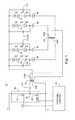
- FIG. 1illustrates a high level schematic diagram of an embodiment of a driving arrangement for four LED strings wherein the anode end of each of the LED strings are commonly coupled to the center tap of a driving transformer, and wherein the cathode ends of the LED strings are each coupled to respective ends of windings of a balancing transformer via respective unidirectional electronic valves;
- FIG. 2illustrates a high level schematic diagram of an embodiment of a driving arrangement for four LED strings wherein the anode end of each of the LED strings are commonly coupled to the center tap of a driving transformer, the cathode ends are each coupled to respective ends of windings of a balancing transformer, and the center taps of the balancing transformer windings are coupled to the driving transformer second winding ends via respective unidirectional electronic valves;
- FIG. 3illustrates a high level schematic diagram of an embodiment of a driving arrangement for two LED strings wherein the anode end of each of the LED strings are commonly coupled to the center tap of a driving transformer, the cathode ends of the LED strings are each coupled to a center tap of respective windings of a balancing transformer, and the balancing transformer winding ends are coupled to the driving transformer second winding ends via respective unidirectional electronic valves;
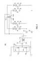
- FIG. 4illustrates a high level schematic diagram of an embodiment of a driving arrangement for four LED strings wherein the cathode ends of a first two of the LED strings are commonly coupled to a first end of the second winding of a driving transformer, the cathode ends of a second two of the LED strings are commonly coupled to a second end of the second winding of the driving transformer, and the anode ends of the LED strings are each coupled to respective ends of windings of a balancing transformer; and
- FIG. 5illustrates a high level schematic diagram of an embodiment of a driving arrangement for two LED strings wherein the cathode end of each of the LED strings are commonly coupled to the center tap of a driving transformer, the anode ends of the LED strings are each coupled to a center tap of respective windings of a balancing transformer, and the balancing transformer winding ends are coupled to the driving transformer second winding ends via respective unidirectional electronic valves.
- FIG. 1illustrates a high level schematic diagram of an embodiment of a driving arrangement 10 comprising: a switching control circuit 20 ; a switching bridge 30 comprising a first electronically controlled switch Q 1 and a second electronically controlled switch Q 2 ; a DC blocking capacitor CX; a driving transformer TX comprising a first winding TXF magnetically coupled to a second winding TXS; first, second, third and fourth LED strings 40 ; a balancing transformer BX comprising a first winding BXF magnetically coupled to a second winding BXS; a first, second, third and fourth smoothing capacitors CS; and a first, second, third and fourth unidirectional electronic valve 50 .
- First and second electronically controlled switches Q 1 , Q 2are illustrated without limitation as NMOSFETs, however this is not meant to be limiting in any way.
- Switching bridge 30is illustrated as a half bridge, however this is not meant to be limiting in any way, and in particular embodiment a full bridge is implemented without exceeding the scope.
- a first output of switching control circuit 20is coupled to the control input of first electronically controlled switch Q 1 of switching bridge 30
- a second output of switching control circuit 20is coupled to the control input of second electronically controlled switch Q 2 of switching bridge 30 .
- the drain of first electronically controlled switch Q 1is coupled to a source of electrical power, denoted V+, and the source of first electronically controlled switch Q 1 is coupled to drain of second electronically controlled switch Q 2 and to a first end of DC blocking capacitor CX.
- the common node of the source of first electronically controlled switch Q 1 , the drain of second electronically controlled switch Q 2 , and the first end of DC blocking capacitor CXis denoted node 35 .
- the second end of DC blocking capacitor CXis coupled to a first end of first winding TXF, and a second end of first winding TXF is coupled to the source of second electronically controlled switch Q 2 , and to the return of the source of electrical power, denoted V ⁇ .
- a center tap of second winding TXSis coupled to the anode end of each of the LED strings 40 and to a first end of each of the smoothing capacitors CS.
- the cathode end of each of the LED strings 40is coupled to a second end of a respective smoothing capacitor CS and to the anode of a respective unidirectional electronic valve 50 .
- the cathode of a first unidirectional electronic valveis coupled to a first end of first winding BXF
- the cathode of a second unidirectional electronic valve 50is coupled to a second end of first winding BXF
- the cathode of a third unidirectional electronic valve 50is coupled to a first end of second winding BXS
- the cathode of a fourth unidirectional electronic valve 50is coupled to a second end of second winding BXS.
- a center tap of first winding BXFis coupled to a first end of second winding TXS
- a center tap of second winding BXSis coupled to a second end of second winding TXS.
- driving arrangement 10provides a balanced current for 4 LED strings 40 with a single balancing transformer BX.
- the 4 LED strings 40are configured with a common anode structure.
- the balancing transformer BXhas two center tapped windings, each of the two windings BXF and BXS having the same number of turns.
- the center taps of BXF, BXS and TXSare each preferably arranged such that an equal number of turns are exhibited between the center tap and the respective opposing ends of the winding.
- Switching control circuit 20is arranged to alternately close first electronically controlled switch Q 1 and second electronically controlled switch Q 2 so as to provide a switching cycle having a first period during which electrical energy is output from second winding TXS with a first polarity and a second period during which electrical energy is output from second winding TXS with a second polarity, the second polarity opposite the first polarity.
- DC blocking capacitor CXensures that the current flowing through first winding TXF, and hence transferred to second winding TXS, during each of the two periods is equal, because DC blocking capacitor CX does not couple DC current in steady state.
- a DC biaswill automatically develop across DC blocking capacitor CX to offset the average operating voltage difference.
- the DC biasacts to maintain an equal total current for each of the two string groups, i.e. the first group comprising two LED strings 40 coupled to first winding BXF and the second group comprising two LED strings 40 coupled to second winding BXS.
- I LED1 +I LED2I LED3 +I LED4 (Responsive to CX) EQ. 1
- I LED1I LED2
- I LED3I LED4 (Responsive to BX) EQ. 2
- Smoothing capacitors CSare each connected in parallel with a respective one of LED strings 40 to smooth out any ripple current and maintain the associated LED current to be nearly a constant direct current.
- Unidirectional electronic valves 50are arranged to block any reverse voltage to LED strings 40 and further prevent bleeding of current between respective smoothing capacitors CS.
- FIG. 2illustrates a high level schematic diagram of an embodiment of a driving arrangement 100 for four LED strings 40 , wherein the anode end of each LED string 40 is commonly coupled to the center tap of second winding TXS of driving transformer TX, the cathode ends of the various LED strings 40 are each coupled to respective ends of windings of balancing transformer BX, and the center taps of the balancing transformer windings, BXS and BXF, are coupled to driving transformer second winding TXS via respective unidirectional electronic valves 50 .
- Driving arrangement 100is a simplified version of driving arrangement 10 , wherein LED strings 40 are allowed to operate with a rippled current, and thus smoothing capacitors CS are not supplied and only a single unidirectional electronic valve 50 is required for each two LED strings 40 .
- the center tap of second winding TXSis commonly coupled to the anode end of each of the four LED strings 40 .
- the cathode end of first LED string 40is coupled to a first end of first winding BXF; the cathode end of second LED string 40 is coupled to a second end of first winding BXF; the cathode end of third LED string 40 is coupled to a first end of second winding BXS; and the cathode end of fourth LED string 40 is coupled to a second end of second winding BXS.
- first winding BXFis coupled via a respective unidirectional electronic valve 50 to a first end of second winding TXS and the center tap of second winding BXS is coupled via a respective unidirectional electronic valve 50 to a second end of second winding TXS.
- Switching control circuit 20is not shown for simplicity, and the connections of switching bridge 30 , DC blocking capacitor CX and first winding TXF are as described above in relation to driving arrangement 10 .
- driving arrangement 100is in all respects similar to the operation of driving arrangement 10 , and thus in the interest of brevity will not be further detailed.
- FIG. 3illustrates a high level schematic diagram of an embodiment of a driving arrangement 200 having two LED strings 40 .
- Switching control circuit 20is not shown for simplicity, and the connections of switching bridge 30 , DC blocking capacitor CX and first winding TXF are as described above in relation to driving arrangement 10 .
- the anode end of each of the LED strings 40are commonly coupled to the center tap of second winding TXS of driving transformer TX.
- the cathode end of a first LED string 40is coupled to a center tap of first winding BXF of balancing transformer BX
- the cathode end of a second LED string 40is coupled to a center tap of second winding BXS of balancing transformer BX.
- first winding BXFare each coupled via a respective unidirectional electronic valve 50 to respective ends of second winding TXS of driving transformer TX and respective ends of second winding BXF are each coupled via a respective unidirectional electronic valve 50 to respective ends of second winding TXS of driving transformer TX.
- Each winding of balancing transformer BXthus drives a single LED string 40 .
- the LED strings 40each conduct in both half cycles and therefore the ripple current frequency is twice that of the switching frequency of Q 1 and Q 2 .
- Opposing halves of first winding BXFconduct during the respective first and second periods generated by switching control circuit 20 and opposing halves of second winding BXS conduct during the respective first and second periods generated by switching control circuit 20 (not shown). Therefore the core of balancer transformer BX experiences an AC excitation.
- the connection polarity of balancer windings BXF and BXSis such so as to always keep the magnetization force generated by the current of the two LED strings 40 in opposite directions, and by such magnetization force the current of the two LED strings 40 are forced to be equal.
- Driving arrangements 10 , 100 and 200illustrate a common anode structure for LED strings 40 , however this is not meant to be limiting in any way, as will be further illustrated below.
- FIG. 4illustrates a high level schematic diagram of an embodiment of a driving arrangement 300 exhibiting four LED strings 40 .
- Switching control circuit 20is not shown for simplicity, and the connections of switching bridge 30 , DC blocking capacitor CX and first winding TXF are as described above in relation to driving arrangement 10 .
- the cathode ends of a first two LED strings 40are commonly coupled to a first end of second winding TXS of driving transformer TX via a common respective unidirectional electronic valve 50 and the cathode ends of a second two LED strings 40 are commonly coupled to a second end of second winding TXS of driving transformer TX via a common respective unidirectional electronic valve 50 .
- the anode end of first LED string 40is coupled to a first end of first winding BXF of balancing transformer BS; the anode end of second LED string 40 is coupled to a second end of first winding BXF of balancing transformer BS; the anode end of third LED string 40 is coupled to a first end of second winding BXS of balancing transformer BS; and the anode end of fourth LED string 40 is coupled to a second end of second winding BXS of balancing transformer BS.
- the center taps of each of first winding BXF and second winding BXSare commonly coupled to the center tap of second winding TXS of driving transformer TX.
- driving arrangement 300is in all respects similar to the operation of driving arrangement 100 , with first and second LED 40 providing illumination during one of the first and second periods, and the third and fourth LED 40 providing illumination during the other of the first and second periods, and in the interest of brevity will not be detailed further.
- FIG. 5illustrates a high level schematic diagram of an embodiment of a driving arrangement 400 for two LED strings 40 wherein the cathode end of each of the LED strings 40 are commonly coupled to the center tap of second winding TXS of driving transformer TX.
- Switching control circuit 20is not shown for simplicity, and the connections of switching bridge 30 , DC blocking capacitor CX and first winding TXF are as described above in relation to driving arrangement 10 .
- the anode end of first LED string 40is coupled to the center tap of first winding BXF of balancing transformer BX and the anode end of second LED string 40 is coupled to the center tap of second winding BXS of balancing transformer BX.
- a first end of first winding BXFis coupled via a respective unidirectional electronic valve 50 to a first end of second winding TXS of driving transformer TX; a second end of first winding BXF is coupled via a respective unidirectional electronic valve 50 to a second end of second winding TXS of driving transformer TX; a first end of second winding BXS is coupled via a respective unidirectional electronic valve 50 to a first end of second winding TXS of driving transformer TX; and a second end of second winding BXS is coupled via a respective unidirectional electronic valve 50 to a second end of second winding TXS of driving transformer TX.
- driving arrangement 400are in all respects identical with the operation of driving arrangement 200 , with the appropriate changes in polarity as required, and thus in the interest of brevity will not be further detailed.
Landscapes
- Circuit Arrangement For Electric Light Sources In General (AREA)
- Electroluminescent Light Sources (AREA)
- Led Devices (AREA)
Abstract
Description
ILED1+ILED2=ILED3+ILED4(Responsive to CX) EQ. 1
ILED1=ILED2, ILED3=ILED4(Responsive to BX) EQ. 2
And as result of EQ. 1 and EQ. 2: ILED1=ILED2=ILED3=ILED4
Claims (20)
Priority Applications (1)
| Application Number | Priority Date | Filing Date | Title |
|---|---|---|---|
| US14/608,242USRE46502E1 (en) | 2011-05-03 | 2015-01-29 | High efficiency LED driving method |
Applications Claiming Priority (3)
| Application Number | Priority Date | Filing Date | Title |
|---|---|---|---|
| US201161482116P | 2011-05-03 | 2011-05-03 | |
| US13/461,793US8598795B2 (en) | 2011-05-03 | 2012-05-02 | High efficiency LED driving method |
| US14/608,242USRE46502E1 (en) | 2011-05-03 | 2015-01-29 | High efficiency LED driving method |
Related Parent Applications (1)
| Application Number | Title | Priority Date | Filing Date |
|---|---|---|---|
| US13/461,793ReissueUS8598795B2 (en) | 2011-05-03 | 2012-05-02 | High efficiency LED driving method |
Publications (1)
| Publication Number | Publication Date |
|---|---|
| USRE46502E1true USRE46502E1 (en) | 2017-08-01 |
Family
ID=46046350
Family Applications (2)
| Application Number | Title | Priority Date | Filing Date |
|---|---|---|---|
| US13/461,793Active2032-07-19US8598795B2 (en) | 2011-05-03 | 2012-05-02 | High efficiency LED driving method |
| US14/608,242Expired - Fee RelatedUSRE46502E1 (en) | 2011-05-03 | 2015-01-29 | High efficiency LED driving method |
Family Applications Before (1)
| Application Number | Title | Priority Date | Filing Date |
|---|---|---|---|
| US13/461,793Active2032-07-19US8598795B2 (en) | 2011-05-03 | 2012-05-02 | High efficiency LED driving method |
Country Status (3)
| Country | Link |
|---|---|
| US (2) | US8598795B2 (en) |
| CN (1) | CN103477712B (en) |
| WO (1) | WO2012151170A1 (en) |
Families Citing this family (6)
| Publication number | Priority date | Publication date | Assignee | Title |
|---|---|---|---|---|
| TWI379482B (en)* | 2009-07-07 | 2012-12-11 | Delta Electronics Inc | Current balance power supplying circuit for plural sets of dc loads |
| CN101888731B (en)* | 2010-07-14 | 2013-11-13 | 成都芯源系统有限公司 | Driving circuit and driving method of light emitting diode |
| US8754581B2 (en)* | 2011-05-03 | 2014-06-17 | Microsemi Corporation | High efficiency LED driving method for odd number of LED strings |
| KR101267278B1 (en) | 2012-11-22 | 2013-05-27 | 이동원 | Led lighting device with improved modulation depth |
| WO2014085723A1 (en)* | 2012-11-30 | 2014-06-05 | Burkhart Scott C | Music synchronized light modulator |
| DE102014200865A1 (en)* | 2014-01-17 | 2015-07-23 | Osram Gmbh | Circuit arrangement for operating light sources |
Citations (190)
| Publication number | Priority date | Publication date | Assignee | Title |
|---|---|---|---|---|
| US2429162A (en) | 1943-01-18 | 1947-10-14 | Boucher And Keiser Company | Starting and operating of fluorescent lamps |
| US2440984A (en) | 1945-06-18 | 1948-05-04 | Gen Electric | Magnetic testing apparatus and method |
| US2572258A (en) | 1946-07-20 | 1951-10-23 | Picker X Ray Corp Waite Mfg | X-ray tube safety device |
| US2965799A (en) | 1957-09-26 | 1960-12-20 | Gen Electric | Fluorescent lamp ballast |
| US2968028A (en) | 1956-06-21 | 1961-01-10 | Fuje Tsushinki Seizo Kabushiki | Multi-signals controlled selecting systems |
| US3141112A (en) | 1962-08-20 | 1964-07-14 | Gen Electric | Ballast apparatus for starting and operating electric discharge lamps |
| US3565806A (en) | 1965-11-23 | 1971-02-23 | Siemens Ag | Manganese zinc ferrite core with high initial permeability |
| US3597656A (en) | 1970-03-16 | 1971-08-03 | Rucker Co | Modulating ground fault detector and interrupter |
| US3611021A (en) | 1970-04-06 | 1971-10-05 | North Electric Co | Control circuit for providing regulated current to lamp load |
| US3683923A (en) | 1970-09-25 | 1972-08-15 | Valleylab Inc | Electrosurgery safety circuit |
| US3737755A (en) | 1972-03-22 | 1973-06-05 | Bell Telephone Labor Inc | Regulated dc to dc converter with regulated current source driving a nonregulated inverter |
| US3742330A (en) | 1971-09-07 | 1973-06-26 | Delta Electronic Control Corp | Current mode d c to a c converters |
| US3936696A (en) | 1973-08-27 | 1976-02-03 | Lutron Electronics Co., Inc. | Dimming circuit with saturated semiconductor device |
| US3944888A (en) | 1974-10-04 | 1976-03-16 | I-T-E Imperial Corporation | Selective tripping of two-pole ground fault interrupter |
| US4060751A (en) | 1976-03-01 | 1977-11-29 | General Electric Company | Dual mode solid state inverter circuit for starting and ballasting gas discharge lamps |
| US4353009A (en) | 1980-12-19 | 1982-10-05 | Gte Products Corporation | Dimming circuit for an electronic ballast |
| US4388562A (en) | 1980-11-06 | 1983-06-14 | Astec Components, Ltd. | Electronic ballast circuit |
| US4441054A (en) | 1982-04-12 | 1984-04-03 | Gte Products Corporation | Stabilized dimming circuit for lamp ballasts |
| US4463287A (en) | 1981-10-07 | 1984-07-31 | Cornell-Dubilier Corp. | Four lamp modular lighting control |
| US4523130A (en) | 1981-10-07 | 1985-06-11 | Cornell Dubilier Electronics Inc. | Four lamp modular lighting control |
| US4562338A (en) | 1983-07-15 | 1985-12-31 | Osaka Titanium Co., Ltd. | Heating power supply apparatus for polycrystalline semiconductor rods |
| US4567379A (en) | 1984-05-23 | 1986-01-28 | Burroughs Corporation | Parallel current sharing system |
| US4572992A (en) | 1983-06-16 | 1986-02-25 | Ken Hayashibara | Device for regulating ac current circuit |
| US4574222A (en) | 1983-12-27 | 1986-03-04 | General Electric Company | Ballast circuit for multiple parallel negative impedance loads |
| US4622496A (en) | 1985-12-13 | 1986-11-11 | Energy Technologies Corp. | Energy efficient reactance ballast with electronic start circuit for the operation of fluorescent lamps of various wattages at standard levels of light output as well as at increased levels of light output |
| US4630005A (en) | 1982-05-03 | 1986-12-16 | Brigham Young University | Electronic inverter, particularly for use as ballast |
| US4663566A (en) | 1984-02-03 | 1987-05-05 | Sharp Kabushiki Kaisha | Fluorescent tube ignitor |
| US4663570A (en) | 1984-08-17 | 1987-05-05 | Lutron Electronics Co., Inc. | High frequency gas discharge lamp dimming ballast |
| US4672300A (en) | 1985-03-29 | 1987-06-09 | Braydon Corporation | Direct current power supply using current amplitude modulation |
| US4675574A (en) | 1985-06-20 | 1987-06-23 | N.V. Adb S.A. | Monitoring device for airfield lighting system |
| US4686615A (en) | 1985-08-23 | 1987-08-11 | Ferranti, Plc | Power supply circuit |
| US4698554A (en) | 1983-01-03 | 1987-10-06 | North American Philips Corporation | Variable frequency current control device for discharge lamps |
| US4700113A (en) | 1981-12-28 | 1987-10-13 | North American Philips Corporation | Variable high frequency ballast circuit |
| US4761722A (en) | 1987-04-09 | 1988-08-02 | Rca Corporation | Switching regulator with rapid transient response |
| US4766353A (en) | 1987-04-03 | 1988-08-23 | Sunlass U.S.A., Inc. | Lamp switching circuit and method |
| US4780696A (en) | 1985-08-08 | 1988-10-25 | American Telephone And Telegraph Company, At&T Bell Laboratories | Multifilar transformer apparatus and winding method |
| US4847745A (en) | 1988-11-16 | 1989-07-11 | Sundstrand Corp. | Three phase inverter power supply with balancing transformer |
| EP0326114A1 (en) | 1988-01-26 | 1989-08-02 | Tokyo Electric Co., Ltd. | Drive device for a discharge lamp |
| US4862059A (en) | 1987-07-16 | 1989-08-29 | Nishimu Electronics Industries Co., Ltd. | Ferroresonant constant AC voltage transformer |
| US4893069A (en) | 1988-06-29 | 1990-01-09 | Nishimu Electronics Industries Co., Ltd. | Ferroresonant three-phase constant AC voltage transformer arrangement with compensation for unbalanced loads |
| US4902942A (en) | 1988-06-02 | 1990-02-20 | General Electric Company | Controlled leakage transformer for fluorescent lamp ballast including integral ballasting inductor |
| US4939381A (en) | 1986-10-17 | 1990-07-03 | Kabushiki Kaisha Toshiba | Power supply system for negative impedance discharge load |
| US5023519A (en) | 1986-07-16 | 1991-06-11 | Kaj Jensen | Circuit for starting and operating a gas discharge lamp |
| US5030887A (en) | 1990-01-29 | 1991-07-09 | Guisinger John E | High frequency fluorescent lamp exciter |
| US5036255A (en) | 1990-04-11 | 1991-07-30 | Mcknight William E | Balancing and shunt magnetics for gaseous discharge lamps |
| US5057808A (en) | 1989-12-27 | 1991-10-15 | Sundstrand Corporation | Transformer with voltage balancing tertiary winding |
| US5173643A (en) | 1990-06-25 | 1992-12-22 | Lutron Electronics Co., Inc. | Circuit for dimming compact fluorescent lamps |
| JPH0590897A (en) | 1991-09-26 | 1993-04-09 | Sony Corp | Oversampling filter circuit |
| EP0587923A1 (en) | 1992-09-14 | 1994-03-23 | U.R.D. Co. Ltd. | High-frequency constant-current feeding system |
| EP0597661A1 (en) | 1992-11-09 | 1994-05-18 | Tunewell Technology Limited | Improvements in or relating to an electrical arrangement |
| JPH06168791A (en) | 1992-11-27 | 1994-06-14 | J T:Kk | Inverter circuit |
| JPH06181095A (en) | 1992-12-11 | 1994-06-28 | Matsushita Electric Works Ltd | Discharge lamp lighting device |
| WO1994015444A1 (en) | 1992-12-23 | 1994-07-07 | Tridonic Bauelemente Gmbh | Ballast for at least one pair of gas discharge lamps in parallel |
| US5349272A (en) | 1993-01-22 | 1994-09-20 | Gulton Industries, Inc. | Multiple output ballast circuit |
| EP0647021A1 (en) | 1993-09-30 | 1995-04-05 | Daimler-Benz Aerospace Aktiengesellschaft | Balanced-unbalanced circuit arrangement |
| US5434477A (en) | 1993-03-22 | 1995-07-18 | Motorola Lighting, Inc. | Circuit for powering a fluorescent lamp having a transistor common to both inverter and the boost converter and method for operating such a circuit |
| US5475284A (en) | 1994-05-03 | 1995-12-12 | Osram Sylvania Inc. | Ballast containing circuit for measuring increase in DC voltage component |
| US5485057A (en) | 1993-09-02 | 1996-01-16 | Smallwood; Robert C. | Gas discharge lamp and power distribution system therefor |
| US5519289A (en) | 1994-11-07 | 1996-05-21 | Jrs Technology Associates, Inc. | Electronic ballast with lamp current correction circuit |
| US5539281A (en) | 1994-06-28 | 1996-07-23 | Energy Savings, Inc. | Externally dimmable electronic ballast |
| JPH08204488A (en) | 1995-01-31 | 1996-08-09 | Nippon Telegr & Teleph Corp <Ntt> | Unbalanced / balanced converter |
| US5557249A (en) | 1994-08-16 | 1996-09-17 | Reynal; Thomas J. | Load balancing transformer |
| US5563473A (en) | 1992-08-20 | 1996-10-08 | Philips Electronics North America Corp. | Electronic ballast for operating lamps in parallel |
| US5574335A (en) | 1994-08-02 | 1996-11-12 | Osram Sylvania Inc. | Ballast containing protection circuit for detecting rectification of arc discharge lamp |
| US5574356A (en) | 1994-07-08 | 1996-11-12 | Northrop Grumman Corporation | Active neutral current compensator |
| WO1996038024A1 (en) | 1995-05-26 | 1996-11-28 | Jon Paul | High efficiency electronic ballast |
| US5615093A (en) | 1994-08-05 | 1997-03-25 | Linfinity Microelectronics | Current synchronous zero voltage switching resonant topology |
| US5619402A (en) | 1996-04-16 | 1997-04-08 | O2 Micro, Inc. | Higher-efficiency cold-cathode fluorescent lamp power supply |
| US5621281A (en) | 1994-08-03 | 1997-04-15 | International Business Machines Corporation | Discharge lamp lighting device |
| US5652479A (en) | 1995-01-25 | 1997-07-29 | Micro Linear Corporation | Lamp out detection for miniature cold cathode fluorescent lamp system |
| US5712776A (en) | 1995-07-31 | 1998-01-27 | Sgs-Thomson Microelectronics S.R.L. | Starting circuit and method for starting a MOS transistor |
| EP0838272A2 (en) | 1996-10-23 | 1998-04-29 | Emerson Electric Co. | Ultrasonic apparatus |
| US5754012A (en) | 1995-01-25 | 1998-05-19 | Micro Linear Corporation | Primary side lamp current sensing for minature cold cathode fluorescent lamp system |
| US5818172A (en) | 1994-10-28 | 1998-10-06 | Samsung Electronics Co., Ltd. | Lamp control circuit having a brightness condition controller having 2.sup.nrd and 4th current paths |
| US5822201A (en) | 1995-03-06 | 1998-10-13 | Kijima Co., Ltd. | Double-ended inverter with boost transformer having output side impedance element |
| US5825133A (en) | 1996-09-25 | 1998-10-20 | Rockwell International | Resonant inverter for hot cathode fluorescent lamps |
| US5854617A (en) | 1995-05-12 | 1998-12-29 | Samsung Electronics Co., Ltd. | Circuit and a method for controlling a backlight of a liquid crystal display in a portable computer |
| US5892336A (en) | 1998-05-26 | 1999-04-06 | O2Micro Int Ltd | Circuit for energizing cold-cathode fluorescent lamps |
| US5910713A (en) | 1996-03-14 | 1999-06-08 | Mitsubishi Denki Kabushiki Kaisha | Discharge lamp igniting apparatus for performing a feedback control of a discharge lamp and the like |
| US5912812A (en) | 1996-12-19 | 1999-06-15 | Lucent Technologies Inc. | Boost power converter for powering a load from an AC source |
| US5914842A (en) | 1997-09-26 | 1999-06-22 | Snc Manufacturing Co., Inc. | Electromagnetic coupling device |
| US5923129A (en) | 1997-03-14 | 1999-07-13 | Linfinity Microelectronics | Apparatus and method for starting a fluorescent lamp |
| US5930126A (en) | 1996-03-26 | 1999-07-27 | The Genlyte Group Incorporated | Ballast shut-down circuit responsive to an unbalanced load condition in a single lamp ballast or in either lamp of a two-lamp ballast |
| US5930121A (en) | 1997-03-14 | 1999-07-27 | Linfinity Microelectronics | Direct drive backlight system |
| US5936360A (en) | 1998-02-18 | 1999-08-10 | Ivice Co., Ltd. | Brightness controller for and method for controlling brightness of a discharge tube with optimum on/off times determined by pulse waveform |
| JPH11238589A (en) | 1998-02-24 | 1999-08-31 | Matsushita Electric Works Ltd | Discharge lamp lighting device |
| JPH11305196A (en) | 1998-04-21 | 1999-11-05 | Alpine Electronics Inc | Method for driving back light lamp |
| US6002210A (en) | 1978-03-20 | 1999-12-14 | Nilssen; Ole K. | Electronic ballast with controlled-magnitude output voltage |
| JP2000030880A (en) | 1998-07-09 | 2000-01-28 | Matsushita Electric Works Ltd | Discharge lamp lighting device |
| US6020688A (en) | 1997-10-10 | 2000-02-01 | Electro-Mag International, Inc. | Converter/inverter full bridge ballast circuit |
| US6028400A (en) | 1995-09-27 | 2000-02-22 | U.S. Philips Corporation | Discharge lamp circuit which limits ignition voltage across a second discharge lamp after a first discharge lamp has already ignited |
| US6037720A (en) | 1998-10-23 | 2000-03-14 | Philips Electronics North America Corporation | Level shifter |
| US6038149A (en) | 1996-12-25 | 2000-03-14 | Kabushiki Kaisha Tec | Lamp discharge lighting device power inverter |
| US6040662A (en) | 1997-01-08 | 2000-03-21 | Canon Kabushiki Kaisha | Fluorescent lamp inverter apparatus |
| US6043609A (en) | 1998-05-06 | 2000-03-28 | E-Lite Technologies, Inc. | Control circuit and method for illuminating an electroluminescent panel |
| US6049177A (en) | 1999-03-01 | 2000-04-11 | Fulham Co. Inc. | Single fluorescent lamp ballast for simultaneous operation of different lamps in series or parallel |
| US6072282A (en) | 1997-12-02 | 2000-06-06 | Power Circuit Innovations, Inc. | Frequency controlled quick and soft start gas discharge lamp ballast and method therefor |
| US6104146A (en) | 1999-02-12 | 2000-08-15 | Micro International Limited | Balanced power supply circuit for multiple cold-cathode fluorescent lamps |
| US6108215A (en) | 1999-01-22 | 2000-08-22 | Dell Computer Corporation | Voltage regulator with double synchronous bridge CCFL inverter |
| US6114814A (en) | 1998-12-11 | 2000-09-05 | Monolithic Power Systems, Inc. | Apparatus for controlling a discharge lamp in a backlighted display |
| US6121733A (en) | 1991-06-10 | 2000-09-19 | Nilssen; Ole K. | Controlled inverter-type fluorescent lamp ballast |
| US6127786A (en) | 1998-10-16 | 2000-10-03 | Electro-Mag International, Inc. | Ballast having a lamp end of life circuit |
| US6127785A (en) | 1992-03-26 | 2000-10-03 | Linear Technology Corporation | Fluorescent lamp power supply and control circuit for wide range operation |
| US6137240A (en) | 1998-12-31 | 2000-10-24 | Lumion Corporation | Universal ballast control circuit |
| US6150772A (en) | 1998-11-25 | 2000-11-21 | Pacific Aerospace & Electronics, Inc. | Gas discharge lamp controller |
| US6169375B1 (en) | 1998-10-16 | 2001-01-02 | Electro-Mag International, Inc. | Lamp adaptable ballast circuit |
| US6181084B1 (en) | 1998-09-14 | 2001-01-30 | Eg&G, Inc. | Ballast circuit for high intensity discharge lamps |
| US6181066B1 (en) | 1997-12-02 | 2001-01-30 | Power Circuit Innovations, Inc. | Frequency modulated ballast with loosely coupled transformer for parallel gas discharge lamp control |
| US6181083B1 (en) | 1998-10-16 | 2001-01-30 | Electro-Mag, International, Inc. | Ballast circuit with controlled strike/restart |
| US6188553B1 (en) | 1997-10-10 | 2001-02-13 | Electro-Mag International | Ground fault protection circuit |
| US6198234B1 (en) | 1999-06-09 | 2001-03-06 | Linfinity Microelectronics | Dimmable backlight system |
| US6198236B1 (en) | 1999-07-23 | 2001-03-06 | Linear Technology Corporation | Methods and apparatus for controlling the intensity of a fluorescent lamp |
| US6215256B1 (en) | 2000-07-07 | 2001-04-10 | Ambit Microsystems Corporation | High-efficient electronic stabilizer with single stage conversion |
| US6218788B1 (en) | 1999-08-20 | 2001-04-17 | General Electric Company | Floating IC driven dimming ballast |
| US6259615B1 (en) | 1999-07-22 | 2001-07-10 | O2 Micro International Limited | High-efficiency adaptive DC/AC converter |
| US6281636B1 (en) | 1997-04-22 | 2001-08-28 | Nippo Electric Co., Ltd. | Neutral-point inverter |
| US6307765B1 (en) | 2000-06-22 | 2001-10-23 | Linfinity Microelectronics | Method and apparatus for controlling minimum brightness of a fluorescent lamp |
| US6310444B1 (en) | 2000-08-10 | 2001-10-30 | Philips Electronics North America Corporation | Multiple lamp LCD backlight driver with coupled magnetic components |
| US6320329B1 (en) | 1999-07-30 | 2001-11-20 | Philips Electronics North America Corporation | Modular high frequency ballast architecture |
| US6323602B1 (en) | 1999-03-09 | 2001-11-27 | U.S. Philips Corporation | Combination equalizing transformer and ballast choke |
| US6344699B1 (en) | 1997-01-28 | 2002-02-05 | Tunewell Technology, Ltd | A.C. current distribution system |
| US20020030451A1 (en) | 2000-02-25 | 2002-03-14 | Moisin Mihail S. | Ballast circuit having voltage clamping circuit |
| US6362577B1 (en) | 1999-06-21 | 2002-03-26 | Koito Manufacturing Co., Ltd. | Discharge lamp lighting circuit |
| US6370444B1 (en)* | 1998-09-30 | 2002-04-09 | Mitsubishi Denki Kabushiki Kaisha | Disc library apparatus |
| US6417631B1 (en) | 2001-02-07 | 2002-07-09 | General Electric Company | Integrated bridge inverter circuit for discharge lighting |
| US6420839B1 (en) | 2001-01-19 | 2002-07-16 | Ambit Microsystems Corp. | Power supply system for multiple loads and driving system for multiple lamps |
| US6433492B1 (en) | 2000-09-18 | 2002-08-13 | Northrop Grumman Corporation | Magnetically shielded electrodeless light source |
| US6441943B1 (en) | 1997-04-02 | 2002-08-27 | Gentex Corporation | Indicators and illuminators using a semiconductor radiation emitter package |
| US6445141B1 (en) | 1998-07-01 | 2002-09-03 | Everbrite, Inc. | Power supply for gas discharge lamp |
| US20020135319A1 (en) | 2001-03-22 | 2002-09-26 | Philips Electronics North America Corp. | Method and system for driving a capacitively coupled fluorescent lamp |
| US6459216B1 (en) | 2001-03-07 | 2002-10-01 | Monolithic Power Systems, Inc. | Multiple CCFL current balancing scheme for single controller topologies |
| US6459215B1 (en) | 2000-08-11 | 2002-10-01 | General Electric Company | Integral lamp |
| US20020140538A1 (en) | 2001-03-31 | 2002-10-03 | Lg. Philips Lcd Co., Ltd. | Method of winding coil and transformer and inverter liquid crystal display having coil wound using the same |
| US20020145886A1 (en) | 2001-04-06 | 2002-10-10 | Stevens Carlile R. | Power inverter for driving alternating current loads |
| US6472827B1 (en) | 1984-10-05 | 2002-10-29 | Ole K. Nilssen | Parallel-resonant inverter-type fluorescent lamp ballast |
| US6472876B1 (en) | 2000-05-05 | 2002-10-29 | Tridonic-Usa, Inc. | Sensing and balancing currents in a ballast dimming circuit |
| US20020171376A1 (en) | 1998-12-11 | 2002-11-21 | Rust Timothy James | Method for starting a discharge lamp using high energy initial pulse |
| US6486618B1 (en) | 2001-09-28 | 2002-11-26 | Koninklijke Philips Electronics N.V. | Adaptable inverter |
| US20020181260A1 (en) | 2001-06-04 | 2002-12-05 | John Chou | Inverter operably controlled to reduce electromagnetic interference |
| US20020180572A1 (en) | 2000-09-14 | 2002-12-05 | Hidenori Kakehashi | Electromagnetic device and high-voltage generating device and method of producing electromagnetic device |
| US6494587B1 (en) | 2000-08-24 | 2002-12-17 | Rockwell Collins, Inc. | Cold cathode backlight for avionics applications with strobe expanded dimming range |
| JP2002367835A (en) | 2001-06-04 | 2002-12-20 | Toko Inc | Inverter transformer |
| US20020195971A1 (en) | 2001-06-18 | 2002-12-26 | Philips Electronics North America Corporation | High efficiency driver apparatus for driving a cold cathode fluorescent lamp |
| US6501234B2 (en) | 2001-01-09 | 2002-12-31 | 02 Micro International Limited | Sequential burst mode activation circuit |
| US20030001524A1 (en) | 2001-06-29 | 2003-01-02 | Ambit Microsystems Corp. | Multi-lamp driving system |
| US20030015974A1 (en) | 2001-07-23 | 2003-01-23 | Patent-Treuhand-Gesellschaft Fur Elektrische Gluhl | Ballast for operating at least one low-pressure discharge lamp |
| US6515427B2 (en) | 2000-12-08 | 2003-02-04 | Advanced Display Inc. | Inverter for multi-tube type backlight |
| US6522558B2 (en) | 2000-06-13 | 2003-02-18 | Linfinity Microelectronics | Single mode buck/boost regulating charge pump |
| US6531831B2 (en) | 2000-05-12 | 2003-03-11 | O2Micro International Limited | Integrated circuit for lamp heating and dimming control |
| US6534934B1 (en) | 2001-03-07 | 2003-03-18 | Ambit Microsystems Corp. | Multi-lamp driving system |
| US20030080695A1 (en) | 2001-10-30 | 2003-05-01 | Mitsubishi Denki Kabushiki Kaisha | Discharge lamp starter |
| US6559606B1 (en) | 2001-10-23 | 2003-05-06 | O2Micro International Limited | Lamp driving topology |
| US20030090913A1 (en) | 2001-11-09 | 2003-05-15 | Ambit Microsystems Corp. | Power supply and inverter used therefor |
| US6570344B2 (en) | 2001-05-07 | 2003-05-27 | O2Micro International Limited | Lamp grounding and leakage current detection system |
| US20030117084A1 (en) | 2001-12-17 | 2003-06-26 | Tom Stack | Ballast with lamp sensor and method therefor |
| US20030122502A1 (en) | 2001-12-28 | 2003-07-03 | Bernd Clauberg | Light emitting diode driver |
| US20030141829A1 (en) | 2002-01-31 | 2003-07-31 | Shan-Ho Yu | Current equalizer assembly for LCD backlight panel |
| TW554643B (en) | 2002-05-10 | 2003-09-21 | Lien Chang Electronic Entpr Co | Multi-lamp driving system |
| US20040000879A1 (en) | 2002-04-12 | 2004-01-01 | Lee Sheng Tai | Circuit structure for driving a plurality of cold cathode fluorescent lamps |
| US6680834B2 (en) | 2000-10-04 | 2004-01-20 | Honeywell International Inc. | Apparatus and method for controlling LED arrays |
| US20040032223A1 (en) | 2002-06-18 | 2004-02-19 | Henry George C. | Square wave drive system |
| US6765354B2 (en) | 2000-10-09 | 2004-07-20 | Tridonicatco Gmbh & Co. Kg | Circuitry arrangement for the operation of a plurality of gas discharge lamps |
| US20040155596A1 (en) | 2003-02-10 | 2004-08-12 | Masakazu Ushijima | Inverter circuit for discharge lamps for multi-lamp lighting and surface light source system |
| US6784627B2 (en) | 2002-09-06 | 2004-08-31 | Minebea Co., Ltd. | Discharge lamp lighting device to light a plurality of discharge lamps |
| US6804129B2 (en) | 1999-07-22 | 2004-10-12 | 02 Micro International Limited | High-efficiency adaptive DC/AC converter |
| US20040257003A1 (en) | 2003-06-23 | 2004-12-23 | Chang-Fa Hsieh | Lamp driving system |
| US20040263092A1 (en) | 2003-04-15 | 2004-12-30 | Da Liu | Driving circuit for multiple cold cathode fluorescent lamps |
| US6864867B2 (en) | 2001-03-28 | 2005-03-08 | Patent-Treuhand-Gesellschaft für elektrische Glühlampen mbH | Drive circuit for an LED array |
| US6870330B2 (en) | 2003-03-26 | 2005-03-22 | Microsemi Corporation | Shorted lamp detection in backlight system |
| US20050093471A1 (en) | 2003-10-06 | 2005-05-05 | Xiaoping Jin | Current sharing scheme for multiple CCF lamp operation |
| US20050093484A1 (en) | 2003-10-21 | 2005-05-05 | Ball Newton E. | Systems and methods for fault protection in a balancing transformer |
| US20050099143A1 (en) | 2003-11-10 | 2005-05-12 | Kazuo Kohno | Drive circuit for illumination unit |
| US20050156539A1 (en) | 2003-12-16 | 2005-07-21 | Ball Newton E. | Lamp current control using profile synthesizer |
| US6922023B2 (en) | 2002-06-26 | 2005-07-26 | Darfon Electronics Corp. | Multiple-lamp backlight inverter |
| US6930893B2 (en) | 2002-01-31 | 2005-08-16 | Vlt, Inc. | Factorized power architecture with point of load sine amplitude converters |
| US20050225261A1 (en) | 2004-04-07 | 2005-10-13 | Xiaoping Jin | Primary side current balancing scheme for multiple CCF lamp operation |
| US20080061716A1 (en) | 2006-09-12 | 2008-03-13 | Lg. Philips Lcd Co. Ltd. | Backlight unit and crystal display device using the same |
| US20080116816A1 (en) | 2006-11-08 | 2008-05-22 | Neuman Robert C | Limited flicker light emitting diode string |
| US20080136769A1 (en) | 2006-09-12 | 2008-06-12 | Lg. Philips Lcd Co. Ltd. | Backlight driving apparatus |
| EP1956288A1 (en) | 2005-11-30 | 2008-08-13 | Sharp Kabushiki Kaisha | Backlight device and liquid crystal display device |
| US20100109560A1 (en) | 2008-11-04 | 2010-05-06 | Jing Jing Yu | Capacitive Full-Wave Circuit for LED Light Strings |
| US20100194199A1 (en) | 2009-02-03 | 2010-08-05 | Sanken Electric Co., Ltd. | Current balancing apparatus, current balancing method, and power supply apparatus |
| US20100237802A1 (en) | 2009-03-18 | 2010-09-23 | Sanken Electric Co., Ltd. | Current balancing device, led lighting device, and lcd b/l module |
| US20100327761A1 (en)* | 2009-06-30 | 2010-12-30 | Microsemi Corporation | Integrated backlight control system |
| EP2278857A2 (en) | 2009-07-17 | 2011-01-26 | Samsung Electronics Co., Ltd. | Backlight assembly and display apparatus having the same |
| US20110068700A1 (en) | 2009-09-21 | 2011-03-24 | Suntec Enterprises | Method and apparatus for driving multiple LED devices |
| US20110216567A1 (en)* | 2010-03-02 | 2011-09-08 | Suntec Enterprises | Single switch inverter |
| US20120062147A1 (en)* | 2010-09-13 | 2012-03-15 | Suntec Enterprises | High efficiency drive method for driving LED devices |
| US20120146546A1 (en)* | 2010-12-09 | 2012-06-14 | Delta Electronics, Inc. | Load current balancing circuit |
| US20120274136A1 (en)* | 2009-11-21 | 2012-11-01 | Inventronics (Hangzhou) Co., Ltd. | Multi-path constant current driving circuit |
Family Cites Families (1)
| Publication number | Priority date | Publication date | Assignee | Title |
|---|---|---|---|---|
| TW556860U (en) | 2001-12-14 | 2003-10-01 | Taiwan Power Conversion Inc | Current equalizer back light plate |
- 2012
- 2012-05-01CNCN201280018780.1Apatent/CN103477712B/enactiveActive
- 2012-05-01WOPCT/US2012/035924patent/WO2012151170A1/enactiveApplication Filing
- 2012-05-02USUS13/461,793patent/US8598795B2/enactiveActive
- 2015
- 2015-01-29USUS14/608,242patent/USRE46502E1/ennot_activeExpired - Fee Related
Patent Citations (213)
| Publication number | Priority date | Publication date | Assignee | Title |
|---|---|---|---|---|
| US2429162A (en) | 1943-01-18 | 1947-10-14 | Boucher And Keiser Company | Starting and operating of fluorescent lamps |
| US2440984A (en) | 1945-06-18 | 1948-05-04 | Gen Electric | Magnetic testing apparatus and method |
| US2572258A (en) | 1946-07-20 | 1951-10-23 | Picker X Ray Corp Waite Mfg | X-ray tube safety device |
| US2968028A (en) | 1956-06-21 | 1961-01-10 | Fuje Tsushinki Seizo Kabushiki | Multi-signals controlled selecting systems |
| US2965799A (en) | 1957-09-26 | 1960-12-20 | Gen Electric | Fluorescent lamp ballast |
| US3141112A (en) | 1962-08-20 | 1964-07-14 | Gen Electric | Ballast apparatus for starting and operating electric discharge lamps |
| US3565806A (en) | 1965-11-23 | 1971-02-23 | Siemens Ag | Manganese zinc ferrite core with high initial permeability |
| US3597656A (en) | 1970-03-16 | 1971-08-03 | Rucker Co | Modulating ground fault detector and interrupter |
| US3611021A (en) | 1970-04-06 | 1971-10-05 | North Electric Co | Control circuit for providing regulated current to lamp load |
| US3683923A (en) | 1970-09-25 | 1972-08-15 | Valleylab Inc | Electrosurgery safety circuit |
| US3742330A (en) | 1971-09-07 | 1973-06-26 | Delta Electronic Control Corp | Current mode d c to a c converters |
| US3737755A (en) | 1972-03-22 | 1973-06-05 | Bell Telephone Labor Inc | Regulated dc to dc converter with regulated current source driving a nonregulated inverter |
| US3936696A (en) | 1973-08-27 | 1976-02-03 | Lutron Electronics Co., Inc. | Dimming circuit with saturated semiconductor device |
| US3944888A (en) | 1974-10-04 | 1976-03-16 | I-T-E Imperial Corporation | Selective tripping of two-pole ground fault interrupter |
| US4060751A (en) | 1976-03-01 | 1977-11-29 | General Electric Company | Dual mode solid state inverter circuit for starting and ballasting gas discharge lamps |
| US6002210A (en) | 1978-03-20 | 1999-12-14 | Nilssen; Ole K. | Electronic ballast with controlled-magnitude output voltage |
| US4388562A (en) | 1980-11-06 | 1983-06-14 | Astec Components, Ltd. | Electronic ballast circuit |
| US4353009A (en) | 1980-12-19 | 1982-10-05 | Gte Products Corporation | Dimming circuit for an electronic ballast |
| US4463287A (en) | 1981-10-07 | 1984-07-31 | Cornell-Dubilier Corp. | Four lamp modular lighting control |
| US4523130A (en) | 1981-10-07 | 1985-06-11 | Cornell Dubilier Electronics Inc. | Four lamp modular lighting control |
| US4700113A (en) | 1981-12-28 | 1987-10-13 | North American Philips Corporation | Variable high frequency ballast circuit |
| US4441054A (en) | 1982-04-12 | 1984-04-03 | Gte Products Corporation | Stabilized dimming circuit for lamp ballasts |
| US4630005A (en) | 1982-05-03 | 1986-12-16 | Brigham Young University | Electronic inverter, particularly for use as ballast |
| US4698554A (en) | 1983-01-03 | 1987-10-06 | North American Philips Corporation | Variable frequency current control device for discharge lamps |
| US4572992A (en) | 1983-06-16 | 1986-02-25 | Ken Hayashibara | Device for regulating ac current circuit |
| US4562338A (en) | 1983-07-15 | 1985-12-31 | Osaka Titanium Co., Ltd. | Heating power supply apparatus for polycrystalline semiconductor rods |
| US4574222A (en) | 1983-12-27 | 1986-03-04 | General Electric Company | Ballast circuit for multiple parallel negative impedance loads |
| US4663566A (en) | 1984-02-03 | 1987-05-05 | Sharp Kabushiki Kaisha | Fluorescent tube ignitor |
| US4567379A (en) | 1984-05-23 | 1986-01-28 | Burroughs Corporation | Parallel current sharing system |
| US4663570A (en) | 1984-08-17 | 1987-05-05 | Lutron Electronics Co., Inc. | High frequency gas discharge lamp dimming ballast |
| US6472827B1 (en) | 1984-10-05 | 2002-10-29 | Ole K. Nilssen | Parallel-resonant inverter-type fluorescent lamp ballast |
| US4672300A (en) | 1985-03-29 | 1987-06-09 | Braydon Corporation | Direct current power supply using current amplitude modulation |
| US4675574A (en) | 1985-06-20 | 1987-06-23 | N.V. Adb S.A. | Monitoring device for airfield lighting system |
| US4780696A (en) | 1985-08-08 | 1988-10-25 | American Telephone And Telegraph Company, At&T Bell Laboratories | Multifilar transformer apparatus and winding method |
| US4686615A (en) | 1985-08-23 | 1987-08-11 | Ferranti, Plc | Power supply circuit |
| US4622496A (en) | 1985-12-13 | 1986-11-11 | Energy Technologies Corp. | Energy efficient reactance ballast with electronic start circuit for the operation of fluorescent lamps of various wattages at standard levels of light output as well as at increased levels of light output |
| US5023519A (en) | 1986-07-16 | 1991-06-11 | Kaj Jensen | Circuit for starting and operating a gas discharge lamp |
| US4939381A (en) | 1986-10-17 | 1990-07-03 | Kabushiki Kaisha Toshiba | Power supply system for negative impedance discharge load |
| US4766353A (en) | 1987-04-03 | 1988-08-23 | Sunlass U.S.A., Inc. | Lamp switching circuit and method |
| US4761722A (en) | 1987-04-09 | 1988-08-02 | Rca Corporation | Switching regulator with rapid transient response |
| US4862059A (en) | 1987-07-16 | 1989-08-29 | Nishimu Electronics Industries Co., Ltd. | Ferroresonant constant AC voltage transformer |
| EP0326114A1 (en) | 1988-01-26 | 1989-08-02 | Tokyo Electric Co., Ltd. | Drive device for a discharge lamp |
| US4902942A (en) | 1988-06-02 | 1990-02-20 | General Electric Company | Controlled leakage transformer for fluorescent lamp ballast including integral ballasting inductor |
| US4893069A (en) | 1988-06-29 | 1990-01-09 | Nishimu Electronics Industries Co., Ltd. | Ferroresonant three-phase constant AC voltage transformer arrangement with compensation for unbalanced loads |
| US4847745A (en) | 1988-11-16 | 1989-07-11 | Sundstrand Corp. | Three phase inverter power supply with balancing transformer |
| US5057808A (en) | 1989-12-27 | 1991-10-15 | Sundstrand Corporation | Transformer with voltage balancing tertiary winding |
| US5030887A (en) | 1990-01-29 | 1991-07-09 | Guisinger John E | High frequency fluorescent lamp exciter |
| US5036255A (en) | 1990-04-11 | 1991-07-30 | Mcknight William E | Balancing and shunt magnetics for gaseous discharge lamps |
| US5173643A (en) | 1990-06-25 | 1992-12-22 | Lutron Electronics Co., Inc. | Circuit for dimming compact fluorescent lamps |
| US6121733A (en) | 1991-06-10 | 2000-09-19 | Nilssen; Ole K. | Controlled inverter-type fluorescent lamp ballast |
| JPH0590897A (en) | 1991-09-26 | 1993-04-09 | Sony Corp | Oversampling filter circuit |
| US6127785A (en) | 1992-03-26 | 2000-10-03 | Linear Technology Corporation | Fluorescent lamp power supply and control circuit for wide range operation |
| US5563473A (en) | 1992-08-20 | 1996-10-08 | Philips Electronics North America Corp. | Electronic ballast for operating lamps in parallel |
| EP0587923A1 (en) | 1992-09-14 | 1994-03-23 | U.R.D. Co. Ltd. | High-frequency constant-current feeding system |
| EP0597661A1 (en) | 1992-11-09 | 1994-05-18 | Tunewell Technology Limited | Improvements in or relating to an electrical arrangement |
| JPH06168791A (en) | 1992-11-27 | 1994-06-14 | J T:Kk | Inverter circuit |
| JPH06181095A (en) | 1992-12-11 | 1994-06-28 | Matsushita Electric Works Ltd | Discharge lamp lighting device |
| WO1994015444A1 (en) | 1992-12-23 | 1994-07-07 | Tridonic Bauelemente Gmbh | Ballast for at least one pair of gas discharge lamps in parallel |
| US5349272A (en) | 1993-01-22 | 1994-09-20 | Gulton Industries, Inc. | Multiple output ballast circuit |
| US5434477A (en) | 1993-03-22 | 1995-07-18 | Motorola Lighting, Inc. | Circuit for powering a fluorescent lamp having a transistor common to both inverter and the boost converter and method for operating such a circuit |
| US5485057A (en) | 1993-09-02 | 1996-01-16 | Smallwood; Robert C. | Gas discharge lamp and power distribution system therefor |
| EP0647021A1 (en) | 1993-09-30 | 1995-04-05 | Daimler-Benz Aerospace Aktiengesellschaft | Balanced-unbalanced circuit arrangement |
| US5475284A (en) | 1994-05-03 | 1995-12-12 | Osram Sylvania Inc. | Ballast containing circuit for measuring increase in DC voltage component |
| US5539281A (en) | 1994-06-28 | 1996-07-23 | Energy Savings, Inc. | Externally dimmable electronic ballast |
| US5574356A (en) | 1994-07-08 | 1996-11-12 | Northrop Grumman Corporation | Active neutral current compensator |
| US5574335A (en) | 1994-08-02 | 1996-11-12 | Osram Sylvania Inc. | Ballast containing protection circuit for detecting rectification of arc discharge lamp |
| US5621281A (en) | 1994-08-03 | 1997-04-15 | International Business Machines Corporation | Discharge lamp lighting device |
| US5615093A (en) | 1994-08-05 | 1997-03-25 | Linfinity Microelectronics | Current synchronous zero voltage switching resonant topology |
| US5557249A (en) | 1994-08-16 | 1996-09-17 | Reynal; Thomas J. | Load balancing transformer |
| US5818172A (en) | 1994-10-28 | 1998-10-06 | Samsung Electronics Co., Ltd. | Lamp control circuit having a brightness condition controller having 2.sup.nrd and 4th current paths |
| US5519289A (en) | 1994-11-07 | 1996-05-21 | Jrs Technology Associates, Inc. | Electronic ballast with lamp current correction circuit |
| US5652479A (en) | 1995-01-25 | 1997-07-29 | Micro Linear Corporation | Lamp out detection for miniature cold cathode fluorescent lamp system |
| US5754012A (en) | 1995-01-25 | 1998-05-19 | Micro Linear Corporation | Primary side lamp current sensing for minature cold cathode fluorescent lamp system |
| JPH08204488A (en) | 1995-01-31 | 1996-08-09 | Nippon Telegr & Teleph Corp <Ntt> | Unbalanced / balanced converter |
| US5822201A (en) | 1995-03-06 | 1998-10-13 | Kijima Co., Ltd. | Double-ended inverter with boost transformer having output side impedance element |
| US5854617A (en) | 1995-05-12 | 1998-12-29 | Samsung Electronics Co., Ltd. | Circuit and a method for controlling a backlight of a liquid crystal display in a portable computer |
| WO1996038024A1 (en) | 1995-05-26 | 1996-11-28 | Jon Paul | High efficiency electronic ballast |
| US5712776A (en) | 1995-07-31 | 1998-01-27 | Sgs-Thomson Microelectronics S.R.L. | Starting circuit and method for starting a MOS transistor |
| US6028400A (en) | 1995-09-27 | 2000-02-22 | U.S. Philips Corporation | Discharge lamp circuit which limits ignition voltage across a second discharge lamp after a first discharge lamp has already ignited |
| US5910713A (en) | 1996-03-14 | 1999-06-08 | Mitsubishi Denki Kabushiki Kaisha | Discharge lamp igniting apparatus for performing a feedback control of a discharge lamp and the like |
| US5930126A (en) | 1996-03-26 | 1999-07-27 | The Genlyte Group Incorporated | Ballast shut-down circuit responsive to an unbalanced load condition in a single lamp ballast or in either lamp of a two-lamp ballast |
| US5619402A (en) | 1996-04-16 | 1997-04-08 | O2 Micro, Inc. | Higher-efficiency cold-cathode fluorescent lamp power supply |
| US5825133A (en) | 1996-09-25 | 1998-10-20 | Rockwell International | Resonant inverter for hot cathode fluorescent lamps |
| EP0838272A2 (en) | 1996-10-23 | 1998-04-29 | Emerson Electric Co. | Ultrasonic apparatus |
| US5828156A (en) | 1996-10-23 | 1998-10-27 | Branson Ultrasonics Corporation | Ultrasonic apparatus |
| US5912812A (en) | 1996-12-19 | 1999-06-15 | Lucent Technologies Inc. | Boost power converter for powering a load from an AC source |
| US6038149A (en) | 1996-12-25 | 2000-03-14 | Kabushiki Kaisha Tec | Lamp discharge lighting device power inverter |
| US6040662A (en) | 1997-01-08 | 2000-03-21 | Canon Kabushiki Kaisha | Fluorescent lamp inverter apparatus |
| US6344699B1 (en) | 1997-01-28 | 2002-02-05 | Tunewell Technology, Ltd | A.C. current distribution system |
| US5930121A (en) | 1997-03-14 | 1999-07-27 | Linfinity Microelectronics | Direct drive backlight system |
| US5923129A (en) | 1997-03-14 | 1999-07-13 | Linfinity Microelectronics | Apparatus and method for starting a fluorescent lamp |
| US6441943B1 (en) | 1997-04-02 | 2002-08-27 | Gentex Corporation | Indicators and illuminators using a semiconductor radiation emitter package |
| US6281636B1 (en) | 1997-04-22 | 2001-08-28 | Nippo Electric Co., Ltd. | Neutral-point inverter |
| US5914842A (en) | 1997-09-26 | 1999-06-22 | Snc Manufacturing Co., Inc. | Electromagnetic coupling device |
| US6281638B1 (en) | 1997-10-10 | 2001-08-28 | Electro-Mag International, Inc. | Converter/inverter full bridge ballast circuit |
| US6188553B1 (en) | 1997-10-10 | 2001-02-13 | Electro-Mag International | Ground fault protection circuit |
| US6020688A (en) | 1997-10-10 | 2000-02-01 | Electro-Mag International, Inc. | Converter/inverter full bridge ballast circuit |
| US6072282A (en) | 1997-12-02 | 2000-06-06 | Power Circuit Innovations, Inc. | Frequency controlled quick and soft start gas discharge lamp ballast and method therefor |
| US6181066B1 (en) | 1997-12-02 | 2001-01-30 | Power Circuit Innovations, Inc. | Frequency modulated ballast with loosely coupled transformer for parallel gas discharge lamp control |
| US5936360A (en) | 1998-02-18 | 1999-08-10 | Ivice Co., Ltd. | Brightness controller for and method for controlling brightness of a discharge tube with optimum on/off times determined by pulse waveform |
| JPH11238589A (en) | 1998-02-24 | 1999-08-31 | Matsushita Electric Works Ltd | Discharge lamp lighting device |
| JPH11305196A (en) | 1998-04-21 | 1999-11-05 | Alpine Electronics Inc | Method for driving back light lamp |
| US6043609A (en) | 1998-05-06 | 2000-03-28 | E-Lite Technologies, Inc. | Control circuit and method for illuminating an electroluminescent panel |
| US5892336A (en) | 1998-05-26 | 1999-04-06 | O2Micro Int Ltd | Circuit for energizing cold-cathode fluorescent lamps |
| US6445141B1 (en) | 1998-07-01 | 2002-09-03 | Everbrite, Inc. | Power supply for gas discharge lamp |
| JP2000030880A (en) | 1998-07-09 | 2000-01-28 | Matsushita Electric Works Ltd | Discharge lamp lighting device |
| US6181084B1 (en) | 1998-09-14 | 2001-01-30 | Eg&G, Inc. | Ballast circuit for high intensity discharge lamps |
| US6370444B1 (en)* | 1998-09-30 | 2002-04-09 | Mitsubishi Denki Kabushiki Kaisha | Disc library apparatus |
| US6169375B1 (en) | 1998-10-16 | 2001-01-02 | Electro-Mag International, Inc. | Lamp adaptable ballast circuit |
| US6181083B1 (en) | 1998-10-16 | 2001-01-30 | Electro-Mag, International, Inc. | Ballast circuit with controlled strike/restart |
| US6127786A (en) | 1998-10-16 | 2000-10-03 | Electro-Mag International, Inc. | Ballast having a lamp end of life circuit |
| US6037720A (en) | 1998-10-23 | 2000-03-14 | Philips Electronics North America Corporation | Level shifter |
| US6150772A (en) | 1998-11-25 | 2000-11-21 | Pacific Aerospace & Electronics, Inc. | Gas discharge lamp controller |
| US6316881B1 (en) | 1998-12-11 | 2001-11-13 | Monolithic Power Systems, Inc. | Method and apparatus for controlling a discharge lamp in a backlighted display |
| US6633138B2 (en) | 1998-12-11 | 2003-10-14 | Monolithic Power Systems, Inc. | Method and apparatus for controlling a discharge lamp in a backlighted display |
| US20020171376A1 (en) | 1998-12-11 | 2002-11-21 | Rust Timothy James | Method for starting a discharge lamp using high energy initial pulse |
| US6114814A (en) | 1998-12-11 | 2000-09-05 | Monolithic Power Systems, Inc. | Apparatus for controlling a discharge lamp in a backlighted display |
| US6137240A (en) | 1998-12-31 | 2000-10-24 | Lumion Corporation | Universal ballast control circuit |
| US6108215A (en) | 1999-01-22 | 2000-08-22 | Dell Computer Corporation | Voltage regulator with double synchronous bridge CCFL inverter |
| US6104146A (en) | 1999-02-12 | 2000-08-15 | Micro International Limited | Balanced power supply circuit for multiple cold-cathode fluorescent lamps |
| US6049177A (en) | 1999-03-01 | 2000-04-11 | Fulham Co. Inc. | Single fluorescent lamp ballast for simultaneous operation of different lamps in series or parallel |
| US6323602B1 (en) | 1999-03-09 | 2001-11-27 | U.S. Philips Corporation | Combination equalizing transformer and ballast choke |
| US6198234B1 (en) | 1999-06-09 | 2001-03-06 | Linfinity Microelectronics | Dimmable backlight system |
| US6362577B1 (en) | 1999-06-21 | 2002-03-26 | Koito Manufacturing Co., Ltd. | Discharge lamp lighting circuit |
| US20010036096A1 (en) | 1999-07-22 | 2001-11-01 | Yung-Lin Lin | High-efficiency adaptive DC/AC converter |
| US20020180380A1 (en) | 1999-07-22 | 2002-12-05 | Yung-Lin Lin | High-efficiency adaptive DC/AC converter |
| US6804129B2 (en) | 1999-07-22 | 2004-10-12 | 02 Micro International Limited | High-efficiency adaptive DC/AC converter |
| US6259615B1 (en) | 1999-07-22 | 2001-07-10 | O2 Micro International Limited | High-efficiency adaptive DC/AC converter |
| US6396722B2 (en) | 1999-07-22 | 2002-05-28 | Micro International Limited | High-efficiency adaptive DC/AC converter |
| US6198236B1 (en) | 1999-07-23 | 2001-03-06 | Linear Technology Corporation | Methods and apparatus for controlling the intensity of a fluorescent lamp |
| US6320329B1 (en) | 1999-07-30 | 2001-11-20 | Philips Electronics North America Corporation | Modular high frequency ballast architecture |
| US6218788B1 (en) | 1999-08-20 | 2001-04-17 | General Electric Company | Floating IC driven dimming ballast |
| US20020030451A1 (en) | 2000-02-25 | 2002-03-14 | Moisin Mihail S. | Ballast circuit having voltage clamping circuit |
| US6472876B1 (en) | 2000-05-05 | 2002-10-29 | Tridonic-Usa, Inc. | Sensing and balancing currents in a ballast dimming circuit |
| US6531831B2 (en) | 2000-05-12 | 2003-03-11 | O2Micro International Limited | Integrated circuit for lamp heating and dimming control |
| US6522558B2 (en) | 2000-06-13 | 2003-02-18 | Linfinity Microelectronics | Single mode buck/boost regulating charge pump |
| US6469922B2 (en) | 2000-06-22 | 2002-10-22 | Linfinity Microelectronics | Method and apparatus for controlling minimum brightness of a flourescent lamp |
| US6307765B1 (en) | 2000-06-22 | 2001-10-23 | Linfinity Microelectronics | Method and apparatus for controlling minimum brightness of a fluorescent lamp |
| US6215256B1 (en) | 2000-07-07 | 2001-04-10 | Ambit Microsystems Corporation | High-efficient electronic stabilizer with single stage conversion |
| US6310444B1 (en) | 2000-08-10 | 2001-10-30 | Philips Electronics North America Corporation | Multiple lamp LCD backlight driver with coupled magnetic components |
| US6459215B1 (en) | 2000-08-11 | 2002-10-01 | General Electric Company | Integral lamp |
| US6494587B1 (en) | 2000-08-24 | 2002-12-17 | Rockwell Collins, Inc. | Cold cathode backlight for avionics applications with strobe expanded dimming range |
| US20020180572A1 (en) | 2000-09-14 | 2002-12-05 | Hidenori Kakehashi | Electromagnetic device and high-voltage generating device and method of producing electromagnetic device |
| US6433492B1 (en) | 2000-09-18 | 2002-08-13 | Northrop Grumman Corporation | Magnetically shielded electrodeless light source |
| US6680834B2 (en) | 2000-10-04 | 2004-01-20 | Honeywell International Inc. | Apparatus and method for controlling LED arrays |
| US6765354B2 (en) | 2000-10-09 | 2004-07-20 | Tridonicatco Gmbh & Co. Kg | Circuitry arrangement for the operation of a plurality of gas discharge lamps |
| US6515427B2 (en) | 2000-12-08 | 2003-02-04 | Advanced Display Inc. | Inverter for multi-tube type backlight |
| US6501234B2 (en) | 2001-01-09 | 2002-12-31 | 02 Micro International Limited | Sequential burst mode activation circuit |
| US20020097004A1 (en) | 2001-01-19 | 2002-07-25 | Yi-Chao Chiang | Power supply system for multiple loads and driving system for multiple lamps |
| US6420839B1 (en) | 2001-01-19 | 2002-07-16 | Ambit Microsystems Corp. | Power supply system for multiple loads and driving system for multiple lamps |
| US6417631B1 (en) | 2001-02-07 | 2002-07-09 | General Electric Company | Integrated bridge inverter circuit for discharge lighting |
| US6534934B1 (en) | 2001-03-07 | 2003-03-18 | Ambit Microsystems Corp. | Multi-lamp driving system |
| US6459216B1 (en) | 2001-03-07 | 2002-10-01 | Monolithic Power Systems, Inc. | Multiple CCFL current balancing scheme for single controller topologies |
| US6509696B2 (en) | 2001-03-22 | 2003-01-21 | Koninklijke Philips Electronics N.V. | Method and system for driving a capacitively coupled fluorescent lamp |
| US20020135319A1 (en) | 2001-03-22 | 2002-09-26 | Philips Electronics North America Corp. | Method and system for driving a capacitively coupled fluorescent lamp |
| US6864867B2 (en) | 2001-03-28 | 2005-03-08 | Patent-Treuhand-Gesellschaft für elektrische Glühlampen mbH | Drive circuit for an LED array |
| US20020140538A1 (en) | 2001-03-31 | 2002-10-03 | Lg. Philips Lcd Co., Ltd. | Method of winding coil and transformer and inverter liquid crystal display having coil wound using the same |
| US20020145886A1 (en) | 2001-04-06 | 2002-10-10 | Stevens Carlile R. | Power inverter for driving alternating current loads |
| US6628093B2 (en) | 2001-04-06 | 2003-09-30 | Carlile R. Stevens | Power inverter for driving alternating current loads |
| US6570344B2 (en) | 2001-05-07 | 2003-05-27 | O2Micro International Limited | Lamp grounding and leakage current detection system |
| US6515881B2 (en) | 2001-06-04 | 2003-02-04 | O2Micro International Limited | Inverter operably controlled to reduce electromagnetic interference |
| US20020181260A1 (en) | 2001-06-04 | 2002-12-05 | John Chou | Inverter operably controlled to reduce electromagnetic interference |
| JP2002367835A (en) | 2001-06-04 | 2002-12-20 | Toko Inc | Inverter transformer |
| US20020195971A1 (en) | 2001-06-18 | 2002-12-26 | Philips Electronics North America Corporation | High efficiency driver apparatus for driving a cold cathode fluorescent lamp |
| US6717372B2 (en) | 2001-06-29 | 2004-04-06 | Ambit Microsystems Corp. | Multi-lamp driving system |
| US20030001524A1 (en) | 2001-06-29 | 2003-01-02 | Ambit Microsystems Corp. | Multi-lamp driving system |
| US6717371B2 (en) | 2001-07-23 | 2004-04-06 | Patent-Treuhand-Gesellschaft für elektrische Glühlampen mbH | Ballast for operating at least one low-pressure discharge lamp |
| US20030015974A1 (en) | 2001-07-23 | 2003-01-23 | Patent-Treuhand-Gesellschaft Fur Elektrische Gluhl | Ballast for operating at least one low-pressure discharge lamp |
| US6486618B1 (en) | 2001-09-28 | 2002-11-26 | Koninklijke Philips Electronics N.V. | Adaptable inverter |
| US6559606B1 (en) | 2001-10-23 | 2003-05-06 | O2Micro International Limited | Lamp driving topology |
| US20030080695A1 (en) | 2001-10-30 | 2003-05-01 | Mitsubishi Denki Kabushiki Kaisha | Discharge lamp starter |
| US20030090913A1 (en) | 2001-11-09 | 2003-05-15 | Ambit Microsystems Corp. | Power supply and inverter used therefor |
| US20030117084A1 (en) | 2001-12-17 | 2003-06-26 | Tom Stack | Ballast with lamp sensor and method therefor |
| US20030122502A1 (en) | 2001-12-28 | 2003-07-03 | Bernd Clauberg | Light emitting diode driver |
| US6930893B2 (en) | 2002-01-31 | 2005-08-16 | Vlt, Inc. | Factorized power architecture with point of load sine amplitude converters |
| US20030141829A1 (en) | 2002-01-31 | 2003-07-31 | Shan-Ho Yu | Current equalizer assembly for LCD backlight panel |
| US6781325B2 (en) | 2002-04-12 | 2004-08-24 | O2Micro International Limited | Circuit structure for driving a plurality of cold cathode fluorescent lamps |
| US20040000879A1 (en) | 2002-04-12 | 2004-01-01 | Lee Sheng Tai | Circuit structure for driving a plurality of cold cathode fluorescent lamps |
| TW554643B (en) | 2002-05-10 | 2003-09-21 | Lien Chang Electronic Entpr Co | Multi-lamp driving system |
| US20060022612A1 (en) | 2002-06-18 | 2006-02-02 | Henry George C | Square wave drive system |
| US20040032223A1 (en) | 2002-06-18 | 2004-02-19 | Henry George C. | Square wave drive system |
| US6922023B2 (en) | 2002-06-26 | 2005-07-26 | Darfon Electronics Corp. | Multiple-lamp backlight inverter |
| US6784627B2 (en) | 2002-09-06 | 2004-08-31 | Minebea Co., Ltd. | Discharge lamp lighting device to light a plurality of discharge lamps |
| US20040155596A1 (en) | 2003-02-10 | 2004-08-12 | Masakazu Ushijima | Inverter circuit for discharge lamps for multi-lamp lighting and surface light source system |
| US6870330B2 (en) | 2003-03-26 | 2005-03-22 | Microsemi Corporation | Shorted lamp detection in backlight system |
| US20040263092A1 (en) | 2003-04-15 | 2004-12-30 | Da Liu | Driving circuit for multiple cold cathode fluorescent lamps |
| US6936975B2 (en) | 2003-04-15 | 2005-08-30 | 02Micro International Limited | Power supply for an LCD panel |
| US20040257003A1 (en) | 2003-06-23 | 2004-12-23 | Chang-Fa Hsieh | Lamp driving system |
| TW200501829A (en) | 2003-06-23 | 2005-01-01 | Benq Corp | Multi-lamp driving system |
| US20050093471A1 (en) | 2003-10-06 | 2005-05-05 | Xiaoping Jin | Current sharing scheme for multiple CCF lamp operation |
| US7242147B2 (en) | 2003-10-06 | 2007-07-10 | Microsemi Corporation | Current sharing scheme for multiple CCF lamp operation |
| US20050093472A1 (en) | 2003-10-06 | 2005-05-05 | Xiaoping Jin | Balancing transformers for ring balancer |
| US20050093483A1 (en) | 2003-10-21 | 2005-05-05 | Ball Newton E. | Systems and methods for a transformer configuration for driving multiple gas discharge tubes in parallel |
| US20050093482A1 (en) | 2003-10-21 | 2005-05-05 | Ball Newton E. | Systems and methods for a transformer configuration with a tree topology for current balancing in gas discharge lamps |
| US20050093484A1 (en) | 2003-10-21 | 2005-05-05 | Ball Newton E. | Systems and methods for fault protection in a balancing transformer |
| US20050099143A1 (en) | 2003-11-10 | 2005-05-12 | Kazuo Kohno | Drive circuit for illumination unit |
| US20050156539A1 (en) | 2003-12-16 | 2005-07-21 | Ball Newton E. | Lamp current control using profile synthesizer |
| US20050162098A1 (en) | 2003-12-16 | 2005-07-28 | Ball Newton E. | Current-mode direct-drive inverter |
| US20050225261A1 (en) | 2004-04-07 | 2005-10-13 | Xiaoping Jin | Primary side current balancing scheme for multiple CCF lamp operation |
| EP1956288A1 (en) | 2005-11-30 | 2008-08-13 | Sharp Kabushiki Kaisha | Backlight device and liquid crystal display device |
| US20080061716A1 (en) | 2006-09-12 | 2008-03-13 | Lg. Philips Lcd Co. Ltd. | Backlight unit and crystal display device using the same |
| US20080136769A1 (en) | 2006-09-12 | 2008-06-12 | Lg. Philips Lcd Co. Ltd. | Backlight driving apparatus |
| US20080116816A1 (en) | 2006-11-08 | 2008-05-22 | Neuman Robert C | Limited flicker light emitting diode string |
| US20100109560A1 (en) | 2008-11-04 | 2010-05-06 | Jing Jing Yu | Capacitive Full-Wave Circuit for LED Light Strings |
| US20100194199A1 (en) | 2009-02-03 | 2010-08-05 | Sanken Electric Co., Ltd. | Current balancing apparatus, current balancing method, and power supply apparatus |
| US20100237802A1 (en) | 2009-03-18 | 2010-09-23 | Sanken Electric Co., Ltd. | Current balancing device, led lighting device, and lcd b/l module |
| US20100327761A1 (en)* | 2009-06-30 | 2010-12-30 | Microsemi Corporation | Integrated backlight control system |
| EP2278857A2 (en) | 2009-07-17 | 2011-01-26 | Samsung Electronics Co., Ltd. | Backlight assembly and display apparatus having the same |
| US20110068700A1 (en) | 2009-09-21 | 2011-03-24 | Suntec Enterprises | Method and apparatus for driving multiple LED devices |
| US20120274136A1 (en)* | 2009-11-21 | 2012-11-01 | Inventronics (Hangzhou) Co., Ltd. | Multi-path constant current driving circuit |
| US20110216567A1 (en)* | 2010-03-02 | 2011-09-08 | Suntec Enterprises | Single switch inverter |
| US20120062147A1 (en)* | 2010-09-13 | 2012-03-15 | Suntec Enterprises | High efficiency drive method for driving LED devices |
| US20120146546A1 (en)* | 2010-12-09 | 2012-06-14 | Delta Electronics, Inc. | Load current balancing circuit |
Non-Patent Citations (16)
| Title |
|---|
| Baddela S M et al; "Parallel Connected LEDs Operated at High Frequency to Improve Current Sharing"; Industry Applications Conference 2004, 39th IAS Annual Meeting, pp. 1677-1681, published Oct. 2004, IEEE Piscataway, NJ. |
| Bradley, D.A., "Power Electronics" 2nd Edition; Chapman & Hall, 1995; Chapter 1, pp. 1-38. |
| Dubey, G. K., "Thyristorised Power Controllers"; Halsted Press, 1986; pp. 74-77. |
| Examination Report for Application No. EP 04794179, dated Oct. 16, 2007. |
| International Search Report by European Patent Office for PCT application PCT/US2011/042909 dated Feb. 6, 2012. |
| International Search Report for parallel PCT application PCT/US2012/035924 mailed Oct. 23, 2012 by European Patent Office. |
| Office Action China Patent Office dated Jun. 5, 2014 for parallel application 201280018780.1. |
| Sungjin Choi et al; "Symmetric Current Balancing Circuit for Multiple DC Loads"; Applied Power Electronics Conference and Exposition 2010; pp. 512-518, published Feb. 2010, IEEE Piscataway, NJ. |
| Supplementary European Search Report for Application No. EP 04794179, dated May 15, 2007. |
| Supplementary European Search Report for Applications No. EP 04794179 dated May 15, 2007. |
| Taiwan Examination Report for Application No. 094110958, dated Mar. 20, 2008, 9 pages. |
| Werner Thomas and Johannes Pforr; A Novel Low-Cost Current-Sharing Method for Automotive LED-Lighting Systems; 13th European Conference on Power Electronics and Applications, 2009. published by IEEE New York, 2009. |
| Werner Thomas et al; "A Novel Low-Cost Current-Sharing Method for Automotive LED Lighting Systems"; 13th European Conference on Power Electronics and Applications, 2009; pp. 1-10, published Sep. 2009, IEEE Piscataway, NJ. |
| Williams, B.W.; "Power Electronics Devices, Drivers, Applications and Passive Components"; Second Edition, McGraw-Hill, 1992; Chapter 10, pp. 218-249. |
| Written Opinion of the International Searching Authority by European Patent Office for PCT application PCT/US2011/042909 dated Feb. 6, 2012. |
| Written Opinion of the International Searching Authority for parallel PCT application PCT/US2012/035924 mailed Oct. 23, 2012 by European Patent Office. |
Also Published As
| Publication number | Publication date |
|---|---|
| US8598795B2 (en) | 2013-12-03 |
| WO2012151170A1 (en) | 2012-11-08 |
| US20120280628A1 (en) | 2012-11-08 |
| CN103477712A (en) | 2013-12-25 |
| CN103477712B (en) | 2015-04-08 |
Similar Documents
| Publication | Publication Date | Title |
|---|---|---|
| US9030119B2 (en) | LED string driver arrangement with non-dissipative current balancer | |
| USRE46502E1 (en) | High efficiency LED driving method | |
| US9839082B2 (en) | LED luminaire driving circuit and method | |
| US9101014B2 (en) | LED controlling circuit with high power factor and an LED lighting device | |
| US20120019156A1 (en) | Led string driver with non-dissipative reactance balancer | |
| US9000673B2 (en) | Multi-channel two-stage controllable constant current source and illumination source | |
| KR20130129957A (en) | Synchronous regulation for led string driver | |
| US20110068700A1 (en) | Method and apparatus for driving multiple LED devices | |
| US20110291574A1 (en) | Multi-channel constant current source and illumination source | |
| US8890424B2 (en) | Illumination device, illumination system, and lamp | |
| US20120062147A1 (en) | High efficiency drive method for driving LED devices | |
| TW201019795A (en) | Light-emitting device | |
| TW201103222A (en) | Current balance power supplying circuit for plural sets of DC loads | |
| TWI422278B (en) | Illuminating apparatus and light source control circuit thereof | |
| CN102137524A (en) | High-efficiency control method for balance-driving light-emitting diode (LED) | |
| CN103745701B (en) | Inverse-excitation type booster circuit, LED-backlit drive circuit and liquid crystal display | |
| US20200375003A1 (en) | Linear constant-current led drive circuit adaptive to wide voltage range | |
| TWI519204B (en) | Light-emitting diode lighting device having multiple driving stages | |
| US8754581B2 (en) | High efficiency LED driving method for odd number of LED strings | |
| US9614452B2 (en) | LED driving arrangement with reduced current spike | |
| CN205408211U (en) | Multichannel LED drive circuit that independently adjusts luminance can flow equalize based on SCC | |
| CN105530724B (en) | Independent dimming multipath LED drive circuit can be flowed based on SCC | |
| TWI462637B (en) | Multi-channel led driver circuit | |
| Hwang et al. | Cost-effective single switch multi-channel LED driver | |
| KR101474081B1 (en) | Light emitting diode driving apparatus |
Legal Events
| Date | Code | Title | Description |
|---|---|---|---|
| AS | Assignment | Owner name:MORGAN STANLEY SENIOR FUNDING, INC., NEW YORK Free format text:PATENT SECURITY AGREEMENT;ASSIGNORS:MICROSEMI CORPORATION;MICROSEMI SEMICONDUCTOR (U.S.) INC. (F/K/A LEGERITY, INC., ZARLINK SEMICONDUCTOR (V.N.) INC., CENTELLAX, INC., AND ZARLINK SEMICONDUCTOR (U.S.) INC.);MICROSEMI FREQUENCY AND TIME CORPORATION (F/K/A SYMMETRICON, INC.);AND OTHERS;REEL/FRAME:037691/0697 Effective date:20160115 | |
| AS | Assignment | Owner name:LED DISPLAY TECHNOLOGIES, LLC, CALIFORNIA Free format text:ASSIGNMENT OF ASSIGNORS INTEREST;ASSIGNOR:MICROSEMI CORPORATION;REEL/FRAME:043137/0738 Effective date:20170721 | |
| AS | Assignment | Owner name:MICROSEMI CORPORATION, CALIFORNIA Free format text:PARTIAL RELEASE OF SECURITY INTEREST IN PATENTS;ASSIGNOR:MORGAN STANLEY SENIOR FUNDING, INC.;REEL/FRAME:043902/0544 Effective date:20170918 | |
| AS | Assignment | Owner name:POLARIS POWERLED TECHNOLOGIES, LLC, CALIFORNIA Free format text:CHANGE OF NAME;ASSIGNOR:LED DISPLAY TECHNOLOGIES, LLC;REEL/FRAME:045084/0315 Effective date:20170925 | |
| AS | Assignment | Owner name:MICROSEMI FREQUENCY AND TIME CORPORATION, CALIFORN Free format text:RELEASE BY SECURED PARTY;ASSIGNOR:MORGAN STANLEY SENIOR FUNDING, INC.;REEL/FRAME:046251/0391 Effective date:20180529 Owner name:MICROSEMI SEMICONDUCTOR (U.S.), INC., CALIFORNIA Free format text:RELEASE BY SECURED PARTY;ASSIGNOR:MORGAN STANLEY SENIOR FUNDING, INC.;REEL/FRAME:046251/0391 Effective date:20180529 Owner name:MICROSEMI CORP. - RF INTEGRATED SOLUTIONS, CALIFOR Free format text:RELEASE BY SECURED PARTY;ASSIGNOR:MORGAN STANLEY SENIOR FUNDING, INC.;REEL/FRAME:046251/0391 Effective date:20180529 Owner name:MICROSEMI COMMUNICATIONS, INC., CALIFORNIA Free format text:RELEASE BY SECURED PARTY;ASSIGNOR:MORGAN STANLEY SENIOR FUNDING, INC.;REEL/FRAME:046251/0391 Effective date:20180529 Owner name:MICROSEMI CORPORATION, CALIFORNIA Free format text:RELEASE BY SECURED PARTY;ASSIGNOR:MORGAN STANLEY SENIOR FUNDING, INC.;REEL/FRAME:046251/0391 Effective date:20180529 Owner name:MICROSEMI CORP. - POWER PRODUCTS GROUP, CALIFORNIA Free format text:RELEASE BY SECURED PARTY;ASSIGNOR:MORGAN STANLEY SENIOR FUNDING, INC.;REEL/FRAME:046251/0391 Effective date:20180529 Owner name:MICROSEMI SOC CORP., CALIFORNIA Free format text:RELEASE BY SECURED PARTY;ASSIGNOR:MORGAN STANLEY SENIOR FUNDING, INC.;REEL/FRAME:046251/0391 Effective date:20180529 | |
| FEPP | Fee payment procedure | Free format text:MAINTENANCE FEE REMINDER MAILED (ORIGINAL EVENT CODE: REM.); ENTITY STATUS OF PATENT OWNER: LARGE ENTITY | |
| LAPS | Lapse for failure to pay maintenance fees | Free format text:PATENT EXPIRED FOR FAILURE TO PAY MAINTENANCE FEES (ORIGINAL EVENT CODE: EXP.); ENTITY STATUS OF PATENT OWNER: LARGE ENTITY |