USRE46432E1 - System and method for spinal implant placement - Google Patents
System and method for spinal implant placementDownload PDFInfo
- Publication number
- USRE46432E1 USRE46432E1US14/824,951US201514824951AUSRE46432EUS RE46432 E1USRE46432 E1US RE46432E1US 201514824951 AUS201514824951 AUS 201514824951AUS RE46432 EUSRE46432 EUS RE46432E
- Authority
- US
- United States
- Prior art keywords
- cannula
- connecting element
- blades
- abutment member
- spine
- Prior art date
- Legal status (The legal status is an assumption and is not a legal conclusion. Google has not performed a legal analysis and makes no representation as to the accuracy of the status listed.)
- Active, expires
Links
Images


Classifications
- A—HUMAN NECESSITIES
- A61—MEDICAL OR VETERINARY SCIENCE; HYGIENE
- A61B—DIAGNOSIS; SURGERY; IDENTIFICATION
- A61B17/00—Surgical instruments, devices or methods
- A61B17/56—Surgical instruments or methods for treatment of bones or joints; Devices specially adapted therefor
- A61B17/58—Surgical instruments or methods for treatment of bones or joints; Devices specially adapted therefor for osteosynthesis, e.g. bone plates, screws or setting implements
- A61B17/68—Internal fixation devices, including fasteners and spinal fixators, even if a part thereof projects from the skin
- A61B17/70—Spinal positioners or stabilisers, e.g. stabilisers comprising fluid filler in an implant
- A61B17/7001—Screws or hooks combined with longitudinal elements which do not contact vertebrae
- A61B17/7035—Screws or hooks, wherein a rod-clamping part and a bone-anchoring part can pivot relative to each other
- A61B17/7037—Screws or hooks, wherein a rod-clamping part and a bone-anchoring part can pivot relative to each other wherein pivoting is blocked when the rod is clamped
- A—HUMAN NECESSITIES
- A61—MEDICAL OR VETERINARY SCIENCE; HYGIENE
- A61B—DIAGNOSIS; SURGERY; IDENTIFICATION
- A61B17/00—Surgical instruments, devices or methods
- A61B17/32—Surgical cutting instruments
- A61B17/3201—Scissors
- A—HUMAN NECESSITIES
- A61—MEDICAL OR VETERINARY SCIENCE; HYGIENE
- A61B—DIAGNOSIS; SURGERY; IDENTIFICATION
- A61B17/00—Surgical instruments, devices or methods
- A61B17/34—Trocars; Puncturing needles
- A61B17/3417—Details of tips or shafts, e.g. grooves, expandable, bendable; Multiple coaxial sliding cannulas, e.g. for dilating
- A61B17/3421—Cannulas
- A—HUMAN NECESSITIES
- A61—MEDICAL OR VETERINARY SCIENCE; HYGIENE
- A61B—DIAGNOSIS; SURGERY; IDENTIFICATION
- A61B17/00—Surgical instruments, devices or methods
- A61B17/56—Surgical instruments or methods for treatment of bones or joints; Devices specially adapted therefor
- A61B17/58—Surgical instruments or methods for treatment of bones or joints; Devices specially adapted therefor for osteosynthesis, e.g. bone plates, screws or setting implements
- A61B17/68—Internal fixation devices, including fasteners and spinal fixators, even if a part thereof projects from the skin
- A61B17/70—Spinal positioners or stabilisers, e.g. stabilisers comprising fluid filler in an implant
- A61B17/7001—Screws or hooks combined with longitudinal elements which do not contact vertebrae
- A61B17/7035—Screws or hooks, wherein a rod-clamping part and a bone-anchoring part can pivot relative to each other
- A—HUMAN NECESSITIES
- A61—MEDICAL OR VETERINARY SCIENCE; HYGIENE
- A61B—DIAGNOSIS; SURGERY; IDENTIFICATION
- A61B17/00—Surgical instruments, devices or methods
- A61B17/56—Surgical instruments or methods for treatment of bones or joints; Devices specially adapted therefor
- A61B17/58—Surgical instruments or methods for treatment of bones or joints; Devices specially adapted therefor for osteosynthesis, e.g. bone plates, screws or setting implements
- A61B17/68—Internal fixation devices, including fasteners and spinal fixators, even if a part thereof projects from the skin
- A61B17/70—Spinal positioners or stabilisers, e.g. stabilisers comprising fluid filler in an implant
- A61B17/7074—Tools specially adapted for spinal fixation operations other than for bone removal or filler handling
- A61B17/7076—Tools specially adapted for spinal fixation operations other than for bone removal or filler handling for driving, positioning or assembling spinal clamps or bone anchors specially adapted for spinal fixation
- A61B17/7082—Tools specially adapted for spinal fixation operations other than for bone removal or filler handling for driving, positioning or assembling spinal clamps or bone anchors specially adapted for spinal fixation for driving, i.e. rotating, screws or screw parts specially adapted for spinal fixation, e.g. for driving polyaxial or tulip-headed screws
- A—HUMAN NECESSITIES
- A61—MEDICAL OR VETERINARY SCIENCE; HYGIENE
- A61B—DIAGNOSIS; SURGERY; IDENTIFICATION
- A61B17/00—Surgical instruments, devices or methods
- A61B17/56—Surgical instruments or methods for treatment of bones or joints; Devices specially adapted therefor
- A61B17/58—Surgical instruments or methods for treatment of bones or joints; Devices specially adapted therefor for osteosynthesis, e.g. bone plates, screws or setting implements
- A61B17/68—Internal fixation devices, including fasteners and spinal fixators, even if a part thereof projects from the skin
- A61B17/70—Spinal positioners or stabilisers, e.g. stabilisers comprising fluid filler in an implant
- A61B17/7074—Tools specially adapted for spinal fixation operations other than for bone removal or filler handling
- A61B17/7083—Tools for guidance or insertion of tethers, rod-to-anchor connectors, rod-to-rod connectors, or longitudinal elements
- A61B17/7085—Tools for guidance or insertion of tethers, rod-to-anchor connectors, rod-to-rod connectors, or longitudinal elements for insertion of a longitudinal element down one or more hollow screw or hook extensions, i.e. at least a part of the element within an extension has a component of movement parallel to the extension's axis
- A—HUMAN NECESSITIES
- A61—MEDICAL OR VETERINARY SCIENCE; HYGIENE
- A61B—DIAGNOSIS; SURGERY; IDENTIFICATION
- A61B17/00—Surgical instruments, devices or methods
- A61B17/56—Surgical instruments or methods for treatment of bones or joints; Devices specially adapted therefor
- A61B17/58—Surgical instruments or methods for treatment of bones or joints; Devices specially adapted therefor for osteosynthesis, e.g. bone plates, screws or setting implements
- A61B17/68—Internal fixation devices, including fasteners and spinal fixators, even if a part thereof projects from the skin
- A61B17/70—Spinal positioners or stabilisers, e.g. stabilisers comprising fluid filler in an implant
- A61B17/7074—Tools specially adapted for spinal fixation operations other than for bone removal or filler handling
- A61B17/7091—Tools specially adapted for spinal fixation operations other than for bone removal or filler handling for applying, tightening or removing longitudinal element-to-bone anchor locking elements, e.g. caps, set screws, nuts or wedges
- A—HUMAN NECESSITIES
- A61—MEDICAL OR VETERINARY SCIENCE; HYGIENE
- A61B—DIAGNOSIS; SURGERY; IDENTIFICATION
- A61B90/00—Instruments, implements or accessories specially adapted for surgery or diagnosis and not covered by any of the groups A61B1/00 - A61B50/00, e.g. for luxation treatment or for protecting wound edges
- A—HUMAN NECESSITIES
- A61—MEDICAL OR VETERINARY SCIENCE; HYGIENE
- A61B—DIAGNOSIS; SURGERY; IDENTIFICATION
- A61B17/00—Surgical instruments, devices or methods
- A61B17/00234—Surgical instruments, devices or methods for minimally invasive surgery
- A—HUMAN NECESSITIES
- A61—MEDICAL OR VETERINARY SCIENCE; HYGIENE
- A61B—DIAGNOSIS; SURGERY; IDENTIFICATION
- A61B17/00—Surgical instruments, devices or methods
- A61B17/56—Surgical instruments or methods for treatment of bones or joints; Devices specially adapted therefor
- A61B17/58—Surgical instruments or methods for treatment of bones or joints; Devices specially adapted therefor for osteosynthesis, e.g. bone plates, screws or setting implements
- A61B17/68—Internal fixation devices, including fasteners and spinal fixators, even if a part thereof projects from the skin
- A61B17/70—Spinal positioners or stabilisers, e.g. stabilisers comprising fluid filler in an implant
- A61B17/7001—Screws or hooks combined with longitudinal elements which do not contact vertebrae
- A61B17/7002—Longitudinal elements, e.g. rods
- A61B17/701—Longitudinal elements with a non-circular, e.g. rectangular, cross-section
- A—HUMAN NECESSITIES
- A61—MEDICAL OR VETERINARY SCIENCE; HYGIENE
- A61B—DIAGNOSIS; SURGERY; IDENTIFICATION
- A61B17/00—Surgical instruments, devices or methods
- A61B17/56—Surgical instruments or methods for treatment of bones or joints; Devices specially adapted therefor
- A61B17/58—Surgical instruments or methods for treatment of bones or joints; Devices specially adapted therefor for osteosynthesis, e.g. bone plates, screws or setting implements
- A61B17/68—Internal fixation devices, including fasteners and spinal fixators, even if a part thereof projects from the skin
- A61B17/70—Spinal positioners or stabilisers, e.g. stabilisers comprising fluid filler in an implant
- A61B17/7001—Screws or hooks combined with longitudinal elements which do not contact vertebrae
- A61B17/7032—Screws or hooks with U-shaped head or back through which longitudinal rods pass
- A—HUMAN NECESSITIES
- A61—MEDICAL OR VETERINARY SCIENCE; HYGIENE
- A61B—DIAGNOSIS; SURGERY; IDENTIFICATION
- A61B17/00—Surgical instruments, devices or methods
- A61B2017/00681—Aspects not otherwise provided for
- A61B2017/00738—Aspects not otherwise provided for part of the tool being offset with respect to a main axis, e.g. for better view for the surgeon
- A—HUMAN NECESSITIES
- A61—MEDICAL OR VETERINARY SCIENCE; HYGIENE
- A61B—DIAGNOSIS; SURGERY; IDENTIFICATION
- A61B17/00—Surgical instruments, devices or methods
- A61B17/34—Trocars; Puncturing needles
- A61B17/3417—Details of tips or shafts, e.g. grooves, expandable, bendable; Multiple coaxial sliding cannulas, e.g. for dilating
- A61B17/3421—Cannulas
- A61B2017/3443—Cannulas with means for adjusting the length of a cannula
- A—HUMAN NECESSITIES
- A61—MEDICAL OR VETERINARY SCIENCE; HYGIENE
- A61B—DIAGNOSIS; SURGERY; IDENTIFICATION
- A61B17/00—Surgical instruments, devices or methods
- A61B17/34—Trocars; Puncturing needles
- A61B17/3417—Details of tips or shafts, e.g. grooves, expandable, bendable; Multiple coaxial sliding cannulas, e.g. for dilating
- A61B17/3421—Cannulas
- A61B2017/3445—Cannulas used as instrument channel for multiple instruments
- A—HUMAN NECESSITIES
- A61—MEDICAL OR VETERINARY SCIENCE; HYGIENE
- A61B—DIAGNOSIS; SURGERY; IDENTIFICATION
- A61B17/00—Surgical instruments, devices or methods
- A61B17/34—Trocars; Puncturing needles
- A61B2017/348—Means for supporting the trocar against the body or retaining the trocar inside the body
- A61B2017/3492—Means for supporting the trocar against the body or retaining the trocar inside the body against the outside of the body
- A—HUMAN NECESSITIES
- A61—MEDICAL OR VETERINARY SCIENCE; HYGIENE
- A61B—DIAGNOSIS; SURGERY; IDENTIFICATION
- A61B90/00—Instruments, implements or accessories specially adapted for surgery or diagnosis and not covered by any of the groups A61B1/00 - A61B50/00, e.g. for luxation treatment or for protecting wound edges
- A61B90/03—Automatic limiting or abutting means, e.g. for safety
- A61B2090/033—Abutting means, stops, e.g. abutting on tissue or skin
- A61B2090/036—Abutting means, stops, e.g. abutting on tissue or skin abutting on tissue or skin
- A—HUMAN NECESSITIES
- A61—MEDICAL OR VETERINARY SCIENCE; HYGIENE
- A61B—DIAGNOSIS; SURGERY; IDENTIFICATION
- A61B90/00—Instruments, implements or accessories specially adapted for surgery or diagnosis and not covered by any of the groups A61B1/00 - A61B50/00, e.g. for luxation treatment or for protecting wound edges
- A61B90/03—Automatic limiting or abutting means, e.g. for safety
- A61B2090/037—Automatic limiting or abutting means, e.g. for safety with a frangible part, e.g. by reduced diameter
- A—HUMAN NECESSITIES
- A61—MEDICAL OR VETERINARY SCIENCE; HYGIENE
- A61B—DIAGNOSIS; SURGERY; IDENTIFICATION
- A61B90/00—Instruments, implements or accessories specially adapted for surgery or diagnosis and not covered by any of the groups A61B1/00 - A61B50/00, e.g. for luxation treatment or for protecting wound edges
- A61B90/39—Markers, e.g. radio-opaque or breast lesions markers
Definitions
- the present inventionrelates generally to implantable devices, and more precisely, to posterior spinal fusion systems.
- pedicle screwsare implanted in the pedicles and are rigidly secured to a rod passing posterior to the pedicles.
- FIG. 1is a perspective view of two adjacent vertebrae of a spine, with guide wires implanted in the pedicles of the right side.
- FIG. 2is a perspective view of three guide wires in isolation, positioned as though implanted in the pedicles of the right sides of three adjacent vertebrae.
- FIG. 3is a perspective view of the guide wires of FIG. 2 , with dilators advanced along the guide wires to dilate surrounding tissue.
- FIG. 4is a perspective view of the guide wires and dilators of FIG. 3 , with hollow dilators placed around the solid dilators.
- FIG. 5is a perspective view of the guide wires and hollow dilators of FIG. 4 , with the solid dilators removed.
- FIG. 6is a perspective view of the guide wires and hollow dilators, with a tapping tool placed over one of the guide wires to tap the corresponding pedicle.
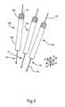
- FIG. 7is an exploded, perspective view of a cannula, abutment member, pedicle screw, cage, set screw, and a portion of a rod according to one embodiment of the invention.
- FIG. 8is a perspective view of the cannula, abutment member, pedicle screw, cage, set screw, and rod portion of FIG. 7 , in assembled form.
- FIG. 9is a perspective view of a screw insertion tool according to one embodiment of the invention.
- FIG. 10is a perspective view of the screw insertion tool of FIG. 9 , in engagement with the assembly of FIG. 8 , excluding the rod portion and the set screw.
- FIG. 11is a perspective view of the screw insertion tool in use to implant the assembly of FIG. 8 , excluding rod portions and set screws, over the first guide wire of FIG. 2 .
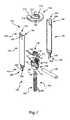
- FIG. 12is a perspective view of a fascia clipping tool according to one embodiment of the invention.
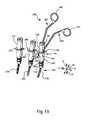
- FIG. 13is a perspective view of the fascia clipping tool of FIG. 12 inserted into one of the cannulas of FIG. 11 to sever the adjoining fascia.
- FIG. 14is a perspective view of a rod insertion tool according to one embodiment of the invention.
- FIG. 15is a perspective view of the rod insertion tool of FIG. 14 secured to a rod to facilitate manual insertion of the rod through the cannulas of FIG. 11 .
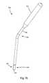
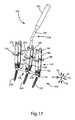
- FIG. 16is a perspective view of a rod seating tool according to one embodiment of the invention.
- FIG. 17is a perspective view of the rod seating tool of FIG. 16 inserted into one of the cannulas of FIG. 11 to help seat the rod in the cages.
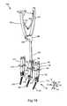
- FIG. 18is a perspective view of a rod holding tool according to one embodiment of the invention.
- FIG. 19is a perspective view of the rod holding tool of FIG. 18 inserted into one of the cannulas of FIG. 11 to further manipulate the rod.
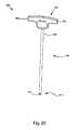
- FIG. 20is a perspective view of a set screw driver according to one embodiment of the invention.
- FIG. 21is a perspective view of the set screw driver of FIG. 20 inserted into one of the cannulas of FIG. 11 to tighten a set screw to retain the rod within the corresponding cage.
- FIG. 22is a perspective view of the pedicle screws, cages, set screws, and cannulas of FIG. 11 , with the abutment members removed to permit removal of the cannulas from the cages.
- FIG. 23is a perspective view of three adjacent vertebrae of the spine, with the rod secured to the pedicle screws to provide posterior spinal fusion.
- FIG. 24is a perspective view of a cannula and cage according to one alternative embodiment of the invention, in which the cannula is secured to the cage by two frangible couplings.
- the present inventionrelates to systems and methods for implantation of orthopedic devices.
- the examples provided hereingenerally relate to insertion of a rod for a posterior spinal fusion system
- the present inventionmay be applied to any procedure in which a device is to be implanted in the body in a minimally invasive manner. Accordingly, the scope of the present invention is not intended to be limited by the examples discussed herein, but only by the appended claims.
- a “cannula”is an elongated structure having a hollow interior that provides communication between opposite ends of the elongated structure.
- a “subcutaneous length”is the portion of an object that lies below the surface of a patient's skin. “Transverse” refers to an object or direction that is not parallel with, and not nearly parallel with, another object or direction.
- a “connecting element”is any man-made structure that is implantable to remain in the body, and is connectable to an anatomic feature and/or another implantable structure.
- percutaneousrefers to an action carried out at least partially underneath unbroken skin.
- discreterefers to parts that are not formed as a single piece, but are separate pieces from each other.
- coupledrefers to two elements that are secured together, whether they have been formed separately and secured together via a secondary operation, or they have been formed as a single piece (i.e., formed in a coupled state).
- curablerefers to elements that are capable of being coupled together, or are already coupled together.
- a “blade”is an elongated, thin structure.
- Polyaxial motionrefers to motion along or about multiple orthogonal axes.
- FIG. 1a perspective view illustrates a portion of a spine 10 .
- FIG. 1illustrates only the bony structures; accordingly, ligaments, cartilage, and other soft tissues are omitted for clarity.
- the spine 10has a cephalad direction 12 , a caudal direction 14 , an anterior direction 16 , a posterior direction 18 , and a medial/lateral axis 20 , all of which are oriented as shown by the arrows bearing the same reference numerals.
- “left” and “right”are used with reference to a posterior view, i.e., a view from behind the spine 10 .
- Medialrefers to a position or orientation toward a sagittal plane (i.e., plane of symmetry that separates left and right sides from each other) of the spine 10
- lateralrefers to a position or orientation relatively further from the sagittal plane.
- the portion of the spine 10 illustrated in FIG. 1includes a first vertebra 24 , which may be the L5 (Fifth Lumbar) vertebra of a patient, and a second vertebra 26 , which may be the L4 (Fourth Lumbar) vertebra of the patient.
- the systems and methodsmay be applicable to any vertebra or vertebrae of the spine 10 and/or the sacrum (not shown).
- the term “vertebra”may be broadly interpreted to include the sacrum.
- the first vertebra 24has a body 28 with a generally disc-like shape and two pedicles 30 that extend posteriorly from the body 28 .
- a posterior arch, or lamina 32extends between the posterior ends of the pedicles 30 to couple the pedicles 30 together.
- the first vertebra 24also has a pair of transverse processes 34 that extend laterally from the pedicles 30 generally along the medial/lateral axis 20 , and a spinous process 36 that extends from the lamina 32 along the posterior direction 18 .
- the first vertebra 24also has a pair of superior facets 38 , which are positioned toward the top of the first vertebra 24 and face generally medially. Additionally, the first vertebra 24 has inferior facets 40 , which are positioned toward the bottom of the first vertebra 24 and face generally laterally. Each of the pedicles 30 of the first vertebra 24 has a saddle point 42 , which is positioned generally at the center of the juncture of each superior facet 38 with the adjacent transverse process 34 .
- the second vertebra 26has a body 48 from which two pedicles 50 extend posteriorly.
- a posterior arch, or lamina 52extends between the posterior ends of the pedicles 50 to couple the pedicles 50 together.
- the second vertebra 26also has a pair of transverse processes 54 , each of which extends from the corresponding pedicle 50 generally along the medial/lateral axis 20 , and a spinous process 56 that extends from the lamina 52 along the posterior direction 18 .
- the second vertebra 26also has a pair of superior facets 58 , which are positioned toward the top of the second vertebra 26 and face generally inward. Additionally, the second vertebra 26 has inferior facets 60 , which are positioned toward the bottom of the second vertebra 26 and face generally outward. Each of the pedicles 60 of the second vertebra 26 has a saddle point 62 , which is positioned generally at the center of the juncture of each superior facet 58 with the adjacent transverse process 54 .
- the superior facets 38 of the first vertebra 24articulate (i.e., slide and/or press) with the inferior facets 60 of the second vertebra 26 to limit relative motion between the first and second vertebrae 24 , 26 .
- the combination of each superior facet 38 with the adjacent inferior facet 60provides a facet joint 64 .
- the first and second vertebrae 24 , 26thus define two facet joints 64 that span the distance between the first and second vertebrae 24 , 26 .
- the inferior facets 40 of the first vertebra 40 and the superior facets 58 of the second vertebra 26are part of other facet joints that control motion between the first and second vertebrae 24 , 26 and adjacent vertebrae (not shown) and/or the sacrum (also not shown).
- FIGS. 1 through 23illustrate one system and method for installing a posterior spinal fusion system.
- FIG. 24illustrates a cannula and cage according to one alternative embodiment of the invention.
- a first guide wire 70has been inserted into the right-side pedicle 30 of the first vertebra 24
- a second guide wire 72has been inserted into the right-side pedicle 50 of the second vertebra 26 .
- the guide wires 70 , 72pass through the saddle points 42 , 62 , respectively, of the pedicles 30 , 50 .
- Each of the guide wires 70 , 72has a proximal end 74 and a distal end 76 . As shown, the proximal ends 74 are exposed, and the distal ends 76 are implanted in the pedicles 30 , 50 .
- the distal ends 76may be implanted by methods known in the surgical arts.
- FIG. 2a perspective view illustrates the first and second guide wires 70 , 72 of FIG. 1 , with the vertebrae 24 , 26 removed for clarity.
- a third guide wire 78is also shown.
- the third guide wire 78is positioned adjacent to the first and second guide wires 70 , 72 as though the third guide wire 78 were implanted in the right-hand pedicle of a vertebra (not shown) directly superior to the second vertebra 26 . Accordingly, the method of FIGS. 1 through 23 may be used to secure together vertebrae on multiple levels, not just two adjacent vertebrae.
- a perspective viewillustrates the guide wires 70 , 72 , 78 , in conjunction with a first dilator 80 , a second dilator 82 , and a third dilator 88 .
- Each of the dilators 180 , 82 , 88has a proximal end 92 and a distal end 94 .
- the proximal ends 92may be shaped for gripping by hand, or for attachment to a handle or the like.
- the distal ends 94are rounded to permit relatively gentle spreading of tissues surrounding the guide wires 70 , 72 , 78 by the dilators 80 , 82 , 88 .
- Each of the dilators 80 , 82 , 88has a bore sized to receive the proximal end 74 of the corresponding guide wire 70 , 72 , or 78 , so that the dilators 80 , 82 , 88 are able to slide along the guide wires 70 , 72 , 78 toward the distal ends 74 , thereby spreading the tissues away from the guide wires 70 , 72 , 78 .
- Each of the dilators 80 , 82 , 88may optionally include a plurality of nesting elements that permit discretely gradual dilation.
- a variety of other guiding devices and/or dilation devicesmay be used within the scope of the present invention.
- FIG. 4a perspective view illustrates the guide wires 70 , 72 , 78 and dilators 80 , 82 , 88 of FIG. 3 , with first, second, and third hollow dilators 100 , 102 , 104 placed around the dilators 80 , 82 , 88 , respectively.
- Each of the hollow dilators 100 , 102 , 104has a generally tubular shape with a proximal end 106 , a distal end 108 , and a bore 110 extending from the proximal end 106 to the distal end 108 .
- Each of the bores 110is sized to receive the outward-facing surface of the corresponding dilator 80 , 82 , 88 .
- the hollow dilators 100 , 102 , 104may simply slide along the anterior direction 16 between the outward-facing surfaces of the dilators 80 , 82 , 88 and the adjoining tissues. The hollow dilators 100 , 102 , 104 then reach the positions shown in FIG. 4 , thereby removing the dilators 80 , 82 , 88 from significant contact with the tissues to be dilated.
- FIG. 5a perspective view illustrates the guide wires 70 , 72 , 78 and hollow dilators 100 , 102 , 104 of FIG. 4 , with the dilators 80 , 82 , 88 removed.
- the dilators 80 , 82 , 88are simply withdrawn along the posterior direction 18 from within the hollow dilators 100 , 102 , 104 to leave the bores 110 of the hollow dilators 100 , 102 , 104 unobstructed.
- a perspective viewillustrates the guide wires 70 , 72 , 78 and hollow dilators 100 , 102 , 104 , with a tapping tool 120 placed over the first guide wire 70 to tap the corresponding pedicle (not shown in FIG. 6 ).
- the tapping tool 120may have a handle 122 shaped to be gripped by hand, and a shank 124 extending from the handle 122 .
- the shank 124has a proximal end 126 coupled to the handle 122 and a distal end 128 having a plurality of threads 130 .
- the tapping tool 120also has a bore (not shown) extending through the shank 124 and through at least a portion of the handle 122 .
- the boreis sized to receive any of the guide wires 70 , 72 , 78 so that the tapping tool 120 can be guided sequentially along each of the guide wires 70 , 72 , 78 to tap the pedicle 30 of the first vertebra 24 , the pedicle 50 of the second vertebra 26 , and the pedicle of the third vertebra (not shown in FIG. 6 ).
- Tappingis carried out by rotating the handle 122 clockwise while exerting axial pressure on the handle 122 to cause the distal end 128 to penetrate the bone. After a pedicle has been tapped, the distal end 128 is withdrawn from the tapped cavity by rotating the handle 122 counterclockwise.
- an exploded, perspective viewillustrates a connecting element 140 , a cannula 142 , an abutment member 144 , and a rod portion 146 according to one embodiment of the invention.
- the rod portion 146is a segment of a longer rod that may be used to secure the first vertebra 24 , the second vertebra 26 , and the third vertebra (not shown in FIG. 7 ) together.
- the connecting element 140is used to secure the rod portion 146 to one pedicle of the vertebrae to be secured together.
- the cannula 142is used to maintain access to the connecting element 140 after it has been implanted in the pedicle in a manner that facilitates percutaneous placement of the rod portion 146 and attachment of the rod portion 146 to the connecting element 140 .
- the abutment member 144helps to hold the cannula 142 together and keep it secured to the connecting element 140 in a manner that will be described subsequently.
- the connecting element 140has a pedicle screw 150 , a cage 152 , and a set screw 154 .
- the pedicle screw 150is the portion of the connecting element 140 that is implanted in the corresponding pedicle.
- the pedicle screw 150is able to hold the cage 152 against the pedicle at any of a variety of orientations of the cage 152 with respect to the pedicle screw 150 .
- the cage 152is polyaxially movable with respect to the pedicle screw 150 until the set screw 154 is tightened into the cage 152 to lock the orientation of the cage 152 with respect to the pedicle screw 150 .
- the pedicle screw 150has a head 160 and a shank 162 .
- the head 160has a convex semispherical underside that engages the cage 152 in any of a variety of relative orientations to provide the polyaxial coupling described previously.
- the head 160also has a hexagonal recess 164 designed to receive a hexagonal end of a pedicle screw driver (not shown in FIG. 7 ), which will be shown and described subsequently.
- the shank 162has a plurality of threads 166 that rotate into threaded engagement with the tapped pedicle.
- the pedicle screw 150also has a bore (not shown) extending through the shank 162 and the head 160 to receive any of the guide wires 70 , 72 , 78 to facilitate guiding of the pedicle screw 150 into engagement with the corresponding pedicle.
- the cage 152has a base 168 in which an aperture 170 is formed.
- the aperture 170is sized such that the shank 162 of the pedicle screw 150 may be inserted through the aperture 170 .
- the head 160 of the pedicle screw 150then rests on a concave semispherical surface of the base 168 , within which the head 160 is polyaxially rotatable.
- the cage 152also has a pair of arms 172 that extend from the base 168 , generally parallel to each other. Each of the arms 172 has a slot 174 and an exterior recess 176 .
- the slots 174pass through the arms 172 to communicate with the slots 174 .
- Each of the arms 172has an inward-facing surface on which a plurality of threads 178 are formed to receive the set screw 154 .
- the arms 172define recesses therebetween, and the recesses form ends of a trough in which the rod portion 146 is able to rest.
- the set screw 154has a hexagonal recess 180 that enables the set screw 154 to be rotated by a driver that will be shown and described subsequently.
- the set screw 154also has an outward-facing surface on which a plurality of threads 182 are formed to enable the set screw 154 to rotate into threaded engagement with the cage 152 .
- the cannula 142Upon assembly, the cannula 142 , which is shown in exploded form in FIG. 7 , will have a proximal end 190 and a distal end 192 .
- the cannula 142may be dimensioned such that the proximal end 190 protrudes above the skin, while the distal end 192 is securable to the cage 152 and is insertable through the skin along with the cage 152 .
- the cannula 142includes a first blade 194 and a second blade 196 , which may be substantially identical to each other.
- Each of the blades 194 , 196has a proximal end 198 corresponding to the proximal end 190 of the cannula 142 , and a distal end 200 corresponding to the distal end 192 of the cannula 142 .
- Each proximal end 198has a proximal tab 202
- each distal end 200has a distal tab 204 .
- Each proximal tab 202has a locking ridge 206 that protrudes generally outward, and extends generally circumferentially.
- Each proximal tab 202is also elongated, with a thin cross section that permits bending toward and away from the axis (not shown) of the cannula.
- Each distal tab 204has bends 208 that cause the distal tab 204 to jut outward, while remaining generally parallel with the remainder of the corresponding blade 194 or 196 .
- Each of the distal tabs 204is insertable through the slot 174 of the adjacent arm 172 of the cage 152 when the corresponding blade 194 or 196 is tilted to position the proximal end 198 inward relative to the distal end 200 .
- rotation of the blades 194 or 196 back to a position generally parallel to each other, and to the axis of the cage 152causes the distal tabs 204 to lie within the exterior recesses 176 of the arms 172 such that the bends 208 are unable to slide back through the slots 174 .
- the blades 194 , 196are then in a locked configuration, and cannot be detached from the cage 152 until they are again moved to the unlocked configuration, i.e., tilted to position the proximal ends 198 inward.
- the distal end 192 of the cannula 142remains secured to the cage 152 .
- the distal tabs 204form a docking element that removably secures the cannula 142 to the connecting element 140 .
- the abutment member 144serves to keep the blades 194 , 196 parallel to each other to keep the cannula 142 in assembled form and to simultaneously keep the cannula 142 secured to the cage 152 by keeping the blades 194 , 196 from rotating into the unlocked configuration.
- the cannula 142When the cannula 142 is secured to the cage 152 , the cannula 142 is in its “docked configuration.” When the cannula 142 is removed from the cage 152 , the cannula 142 is in its “undocked configuration.”
- the abutment member 144is generally disc-shaped with a central opening 212 and an open side 214 that provides access to the central opening 212 .
- the abutment member 144also has an interior recess 216 in communication with the central opening 212 .
- the abutment member 144has a pair of arcuate slots 218 that extend around opposing portions of the central opening 212 and are generally coaxial with the central opening 212 .
- the arcuate slots 218are sized to receive the first and second blades 194 , 196 and to keep the first and second blades 194 , 196 generally parallel to each other, and perpendicular to the abutment member 144 .
- the blades 194 , 196are unable to pivot to the unlocked configuration and the cannula 142 maintains a generally tubular shape.
- the proximal ends 198may be inserted through the arcuate slots 218 of the abutment member 144 .
- Each of the locking ridges 206has a wedge-like profile. Accordingly, as the locking ridges 206 pass through the arcuate slots 218 , the proximal tabs 202 are urged to bend inward.
- the proximal tabs 202act as a locking mechanism that restricts withdrawal of the abutment member 144 from around the cannula 142 .
- the abutment member 144may be positioned at any of a range of positions along the cannula 142 .
- the abutment member 144will abut the outward-facing surface of the patient's skin through which the cannula 142 passes.
- the abutment member 144helps to stabilize the cannula 142 with respect to the tissues it passes through.
- FIG. 8a perspective view illustrates the connecting element 140 , the cannula 142 , the abutment member 144 , and the rod portion 146 of FIG. 7 , in assembled form.
- the shank 162 of the pedicle screw 150has been inserted through the aperture 170 such that the head 160 of the pedicle screw 150 rests against the base 168 of the cage 152 .
- the rod portion 146has been positioned between the arms 172 and the set screw 154 has been rotated into engagement with the threads 166 of the arms 172 to keep the rod portion 146 in place and restrict further rotation of the cage 152 relative to the pedicle screw 150 .
- the distal tabs 204have also been inserted through the slots 174 of the arms 172 of the cage 152 , and the blades 194 , 196 have been rotated into the locked configuration.
- the proximal ends 198 of the blades 194 , 196have been inserted through the arcuate slots 218 of the abutment member 144 to keep the blades 194 , 196 in assembled form to define the cannula 142 , and to keep the cannula 142 secured to the cage 152 .
- the blades 194 , 196may still be said to define the cannula 142 , although the cannula 142 then has a tapered shape.
- the cannula 142has slots 220 extending along its entire longitudinal length, along opposite sides of the cannula 142 .
- the slots 220extend to the cage 152 , and are therefore contiguous with the recesses defined by the arms 172 of the cage 152 .
- the slots 220will extend along the entire subcutaneous length of the cannula 142 . Therefore, the rod portion 146 may be inserted percutaneously through the slots 220 along a direction transverse to the axis of the cannula 146 , and may then be moved through the slots 220 along the anterior direction 16 , directly into the trough of the cage 152 .
- FIG. 9a perspective view illustrates a screw insertion tool 230 according to one embodiment of the invention.
- the screw insertion tool 230has a driver 232 designed to rotate the pedicle screw 150 into threaded engagement with the corresponding tapped pedicle, and a countertorque member 234 that maintains the orientation of the cage 152 during rotation of the pedicle screw 150 .
- the driver 232has a handle 236 designed to be rotated by hand, and a shank 238 extending from the handle 236 .
- the shank 238has a proximal end 240 and distal end 242 shaped to drive the pedicle screw 150 .
- the distal end 242has a hexagonal projection 244 that fits into the hexagonal recess 164 of the head 160 of the pedicle screw 150 .
- the driver 232also has a bore 246 sized to receive any of the guide wires 70 , 72 , 78 ; the bore 246 extends through at least a portion of the shank 238 and, optionally, through all or part of the handle 236 to permit the screw insertion tool 230 to be easily guided along each of the guide wires 70 , 72 , 78 .
- the countertorque member 234has a bore 248 that extends along its entire length, through which the shank 238 of the driver 232 passes.
- the bore 248is large enough to permit easy relative rotation between the driver 232 and the countertorque member 234 .
- the countertorque member 234also has a generally tubular shape with a proximal end 250 and a distal end 252 .
- the proximal end 250has a plurality of longitudinal ridges 254 designed to be gripped by a user's fingers to restrict rotation of the countertorque member 234 .
- the distal end 252has a plurality of threads 256 designed to threadably engage the threads 178 of the arms 172 of the cage 152 .
- the distal end 252 of the countertorque member 234can be rotated into engagement with the cage 152 to secure the countertorque member 234 to the cage 152 , thereby allowing a user to hold the longitudinal ridges 254 to keep the cage 152 stationary during rotation of the driver 232 .
- the countertorque member 234also has longitudinal slots 258 that provide access to the bore 248 of the countertorque member 234 for cleaning or other purposes.
- FIG. 10a perspective view illustrates the screw insertion tool 230 of FIG. 9 , in engagement with the assembly of FIG. 8 , excluding the rod portion 146 and the set screw 154 .
- the threads 256 of the distal end 252have been rotated into engagement with the threads 178 of the arms 172 , and the hexagonal projection 244 has been inserted into the hexagonal recess 164 of the head 160 of the pedicle screw 150 .
- the screw insertion tool 230is thus ready to implant the pedicle screw 150 into the corresponding tapped pedicle.
- a screw insertion toolmay have a countertorque member that functions independently of threaded engagement with the cage 152 .
- a counter-torque member(not shown) may have et projections that slide into the recesses between the arms 172 , or engage other features of the cage 152 , to prevent relative rotation between the cage 152 and the countertorque member.
- FIG. 11a perspective view illustrates the screw insertion tool 230 in use to implant the assembly of FIG. 8 , excluding rod portions 146 and set screws 154 , over the first guide wire 70 of FIG. 2 .
- the handle 236may be used to actuate the connecting element 140 , the cannula 142 , and the abutment member 144 along the first guide wire 70 .
- the handle 236Upon contact of the pedicle screw 150 with the tapped pedicle 30 (not shown in FIG. 11 ), the handle 236 is rotated while the countertorque member 234 is restrained from rotation via application of pressure on the longitudinal ridges 254 .
- the pedicle screw 150is rotated into engagement with the pedicle while keeping the cage 152 , the cannula 142 , and the abutment member 144 at a relatively constant orientation.
- the cannula 142is oriented such that the slots 220 generally face in the cephalad direction 12 and the caudal direction 14 .
- a second connecting element 260has been implanted in the pedicle 50 of the second vertebra 26 (not shown in FIG. 11 ).
- a second cannula 262 and a second abutment member 264have been secured to the second connecting element 260 in a manner similar to that of the cannula 142 and the abutment member 144 .
- a third connecting element 270has been implanted in the pedicle of the third vertebra (not shown in FIG. 11 ).
- a third cannula 272 and a third abutment member 274have been secured to the third connecting element 270 in a manner similar to that of the cannula 142 and the abutment member 144 .
- the second connecting element 260 , cannula 262 , and abutment member 264 and the third connecting element 270 , cannula 272 , and abutment member 274may be substantially identical to the connecting element 140 , the cannula 142 , and the abutment member 144 , as shown in FIGS. 7 and 8 .
- a perspective viewillustrates a fascia clipping tool 280 according to one embodiment of the invention.
- the fascia clipping tool 280has a first member 282 and a second member 284 pivotably secured to the first member 284 through the use of a pin 286 .
- the first member 282has a finger loop 288 designed to receive a user's finger, and a blade 290 extending at a predefined angle from the remainder of the first member 282 .
- the second member 284has a finger loop 292 and a blade 294 .
- the blades 290 , 294have inwardly-oriented sharp edges that provide a scissoring effect when the blades 290 , 294 are brought into a parallel configuration.
- FIG. 13a perspective view illustrates the fascia clipping tool 280 of FIG. 12 inserted into the cannula 142 of FIG. 11 to sever the adjoining fascia (not shown).
- the skin between the cannulas 142 , 262 , 272need not be severed; rather, only the subcutaneous fascia is cut to provide unimpeded percutaneous access to the cages 152 of the connecting elements 150 , 260 , 270 .
- each of the abutment members 144 , 264 , 274provides the appropriate range of relative motion in the cephalad and caudal directions 12 , 14 for the first and second members 282 , 284 to permit relatively easy cutting of the fascia with little or no damage to the surrounding tissue (not shown).
- a perspective viewillustrates a rod insertion tool 300 according to one embodiment of the invention.
- the rod insertion tool 300has a handle 302 shaped to be grasped by hand, and a shank 304 extending from the handle 302 .
- the handle 302has a knob 306 that can be rotated by hand to control retention of a rod (not shown in FIG. 14 ) by the rod insertion tool 300 .
- the shank 304has a proximal end 308 secured to the handle 302 and a distal end 310 that receives and is securable to the end of the rod.
- the distal end 310may have a rod coupling 312 securable to the rod through the use of a mechanism such as a collet or gripper. Such a mechanism may be actuated by rotating the knob 306 .
- a mechanismsuch as a collet or gripper.
- an interference fit or another similar mechanismmay be used to retain the rod in such a manner that the rod can be removed when a threshold removal force is applied.
- the shank 304has a plurality of slots 314 distributed along the length of the shank 304 to provide access to a bore (not shown) of the shank 304 for cleaning or other purposes.
- a perspective viewillustrates the rod insertion tool 300 of FIG. 14 secured to a rod 316 to facilitate manual insertion of the rod 316 through the cannulas 142 , 262 , 272 of FIG. 11 .
- the rod 316has a leading end 317 and a trailing end 318 secured to the rod coupling 312 of the rod insertion tool 300 .
- the rod 316may be contoured based on the morphology of the patient's spine so that the rod 316 will maintain the proper lordotic angle between the first vertebra 24 , the second vertebra 26 , and the third vertebra.
- the rod 316may be pre-lordosed to provide a lordotic angle suitable for most patients.
- the rod 316may optionally be selected from a kit (not shown) containing multiple, differently angled rods.
- the leading end 317is first inserted through the skin (not shown) of the patient by inserting the leading end 317 through the proximal end 190 of the cannula 142 , and through the central opening 212 of the abutment member 144 .
- the handle 302is manipulated to insert the leading end 317 through the opening formed in the fascia, through the slots 220 of the second cannula 262 , and through at least one slot 220 of the third cannula 272 and/or through at least one recess of the cage 152 of the third connecting element 270 .
- the rod 316may be detached from the rod insertion tool 300 .
- a perspective viewillustrates a rod seating tool 320 according to one embodiment of the invention.
- the rod seating tool 320has a handle 322 shaped to be gripped by hand, and a shank 324 extending from the handle 322 .
- the shank 324has a proximal end 326 adjacent to the handle 322 and a distal end 328 shaped to push the rod 316 into place. More precisely, the distal end 328 may have a blade 330 with a generally thin cross section.
- the blade 330may terminate in an arcuate recess 332 with a radius matching that of the rod 316 .
- a perspective viewillustrates the rod seating tool 320 of FIG. 16 inserted into the second cannula 262 of FIG. 11 to help seat the rod 316 in the cages 152 of the connecting elements 140 , 260 , 270 .
- the distal end 328 of the rod seating tool 320may simply be inserted through the second cannula 262 until the arcuate recess 332 of the blade 330 abuts the rod 316 .
- pressureis applied via the handle 322 to urge the rod 316 to slide along the slots 220 , in the anterior direction 16 until the rod 316 is seated generally within the troughs of the cages 152 of the connecting elements 140 , 260 , 270 .
- the distal end 328may similarly be inserted into the cannula 142 , the third cannula 272 , or any combination of the cannulas 142 , 262 , 272 until the rod 316 has been positioned to pass through all of the cages 152 .
- FIG. 18a perspective view illustrates a rod holding tool 18 according to one embodiment of the invention.
- the rod holding tool 18is designed to grip the rod 316 to permit translation of the rod 316 along its axis or rotation of the rod 316 about its axis.
- the rod holding tool 18has first handle 342 , a second handle 344 , a central body 346 , a shank 348 , a pin 350 , a first leaf spring 352 , a second leaf spring 354 , and a pair of screws 356 .
- the first handle 342has a proximal end 360 and a distal end 362 .
- the proximal end 360has a transverse extension 364 that facilitates gripping of the first handle 342 , for example, with the fingers of one hand.
- the proximal end 360also has a hole 366 with threads designed to receive threads (not shown) of the corresponding screw 356 .
- the distal end 362has a blade 368 that is pivotably coupled to the central body 346 by the pin 350 .
- the second handle 344has a proximal end 370 and a distal end 372 .
- the proximal end 370has a hole (not shown) similar to the hole 366 of the proximal end 360 of the first handle 342 .
- the distal end 372may be formed as a single piece with the central body 346 .
- the central body 346has a slot 374 that receives the blade 368 of the distal end 362 of the first handle 342 .
- the pin 350passes through the slot 374 to extend through the blade 368 , thereby providing the pivotable coupling between the central body 346 and the first handle 342 .
- the central body 346also has a projection 376 that extends generally distally.
- the shank 348has a proximal end 380 at which the shank 348 is secured to the projection 376 of the central body 346 , and a distal end 382 designed to grip the rod 316 in response to pressure applied to squeeze the first and second handles 342 , 344 together. More precisely, the distal end 382 has an arcuate recess 384 with a radius matched to that of the rod 316 , and an arcuate extension 386 with a radius equal or similar to that of the arcuate recess 384 .
- the shank 348also has a stationary arm 387 and a sliding arm 388 , each of which has a generally half-circular cross sectional shape.
- the stationary arm 387is rigidly attached to the projection 376
- the sliding arm 388is slidably coupled to the stationary arm 387 .
- the arcuate extension 386is on the stationary arm 387
- the arcuate recess 384is on the sliding arm 388 .
- the sliding arm 388is coupled to the blade 368 of the first handle 342 within the central body 346 such that pivotal motion of the first handle 342 urges the sliding arm 388 to slide distally along the stationary arm 387 .
- the first leaf spring 352has a fixed end 390 secured to the first handle 342 by the corresponding screw 356 , and a coupled end 392 coupled to the second leaf spring 354 .
- the second leaf spring 354has a fixed end 394 secured to the second handle 344 by the other screw 356 , and a coupled end 396 coupled to the coupled end 392 of the first leaf spring 352 .
- the coupled ends 392 , 396may be interlocked in an interdigitated manner that permits relative rotation of the coupled ends 392 , 396 .
- leaf springs 352 , 354cooperate to provide resilient force urging the first and second handles 342 , 344 to move apart, thereby urging the distal end 382 of the shank 348 to release the rod 316 in the absence of force urging the handles 342 , 344 together.
- a portion of the rod 316may first be positioned to abut the arcuate surface of the arcuate extension 386 .
- the sliding arm 388slides distally along the stationary arm 387 .
- the arcuate recess 384moves toward the arcuate extension 386 until the arcuate surface of the arcuate recess 384 is contiguous with the arcuate surface of the arcuate extension 386 .
- the arcuate recess 384then cooperates with the arcuate extension 386 to capture the rod 316 so that the rod holding tool 340 can be used to axially rotate or translate the rod 316 , as desired.
- FIG. 19a perspective view illustrates the rod holding tool 340 of FIG. 18 inserted into the second cannula 262 of FIG. 11 to further manipulate the rod 316 .
- the distal end 382 of the shank 348has been inserted through the second cannula 262 to position the arcuate extension 386 adjacent to the rod 316 .
- the first and second handles 342 , 344have also been squeezed together to slide the arcuate recess 384 against the rod 316 to capture the rod 316 .
- the rod 316can be translated or rotated in any direction.
- the rod 316may be rotated axially through the use of the rod holding tool 340 .
- the rod 316may also be translated axially if needed. Fluoroscopy or other known methods may be used to check the position and orientation of the rod 316 with respect to the cages 152 .
- a perspective viewillustrates a set screw driver 400 according to one embodiment of the invention.
- the set screw driver 400has a handle 402 and a shank 404 extending from the handle 402 .
- the handle 402has a pair of oppositely disposed transverse extensions 406 that protrude to facilitate manual gripping and rotation of the handle 402 .
- the shank 404has a proximal end 408 adjacent to the handle 402 and a distal end 410 designed to transmit torque to the set screw 154 .
- the distal end 410may have a hexagonal projection 412 insertable into the hexagonal recess 180 of the set screw 154 .
- FIG. 21a perspective view illustrates the set screw driver 400 of FIG. 20 inserted into the cannula 142 of FIG. 11 to tighten the corresponding set screw 154 to retain the rod 316 within the corresponding cage 152 .
- the set screws 154may be applied after the rod 316 has been properly positioned with respect to the cages 152 .
- the hexagonal projection 412may first be inserted into the hexagonal recess 180 of the set screw 154 . Then, the handle 402 may be gripped and used to insert the set screw 154 into position adjacent to the threads 178 of the arms 172 of the cage 152 of the connecting element 140 . The handle 402 may then be rotated clockwise to cause the threads 182 of the set screw 154 to rotate into engagement with the threads 178 . The handle 402 may be rotated clockwise until the set screw 154 presses firmly against the rod 316 to keep the rod 316 in place within the corresponding cage 152 , and to restrict further rotation of the cage 152 with respect to the corresponding pedicle screw 150 . All three of the set screws 154 may be positioned and tightened in this manner to complete assembly of the posterior spinal fusion system.
- a countertorque member(not shown) may be provided. Such a countertorque member may engage the cage 152 to keep the cage 152 from rotating while the set screw 154 is tightened.
- FIG. 22a perspective view illustrates the fully assembled posterior spinal fusion system including the connecting elements 140 , 260 , 270 and the rod 316 , with the cannulas 142 , 262 , 272 still secured to the cages 152 of the connecting elements 140 , 260 , 270 , but with the abutment members 144 , 264 , 274 removed from the cannulas 142 , 262 , 272 .
- the abutment members 144 , 264 , 274may be removed from the cannulas 142 , 262 , 272 by squeezing the proximal tabs 202 of each cannula 142 , 262 , 272 together, for example, with the thumb and forefinger of a hand.
- the locking ridges 206are thereby moved into alignment with the arcuate slots 218 of the abutment members 144 , 264 , 274 so that the abutment members 144 , 264 , 274 can be withdrawn along the posterior direction 18 from the corresponding cannulas 142 , 262 , 272 , respectively.
- each cannula 142 , 262 , 272may be pivoted into the unlocked configuration.
- the distal tabs 204may then be withdrawn from the slots 174 of the arms 172 of the cages 152 , and out of the patient's body. Then, the incisions made to accommodate the cannulas 142 , 262 , 272 may be closed and treated through the use of methods known in the art.
- FIG. 23a perspective view illustrates the completed posterior spinal fusion system.
- FIG. 23illustrates a third vertebra 428 superior to the second vertebra 26 .
- the third vertebra 428has features similar to those set forth in the description of the first and second vertebrae 24 , 26 . Most pertinently, the third vertebra 428 has pedicles 430 with saddle points 432 .
- the pedicle screw 150 of the first connecting element 140is implanted in the pedicle 30 of the right side of the first vertebra 24
- the pedicle screw 150 of the second connecting element 260is implanted in the pedicle 50 of the right side of the second vertebra 26
- the pedicle screw 150 of the third connecting element 270is implanted in the pedicle 430 of the right side of the third vertebra 428 .
- the rod 316passes through the troughs of the cages 152 in a manner that preserves the proper lordosis of the spine 10 .
- the set screws 154have been rotated into engagement with the cages 152 and tightened to keep the rod 316 in place within the troughs of the cages 152 and to substantially eliminate rotation of the cages 152 relative to their respective vertebrae 24 , 26 , 428 .
- the connecting elements 140 , 260 , 270thus cooperate with the rod 316 to restrict relative motion of the vertebrae 24 , 26 , 428 to form a posterior vertebral fusion system.
- a similar systemmay be implanted in the left-side pedicles 30 , 50 , 430 of the vertebrae 24 , 26 , 428 through the method set forth previously to provide a bilateral system.
- the present inventionis not limited to a three-level fusion system, but may be used to fuse any number of vertebrae together. To fuse more than three vertebrae together, the steps set forth above may simply be repeated for each additional vertebra, and the rod may be inserted through the skin via a first cannula, and then percutaneously inserted through three or more additional cannulas.
- FIGS. 1-23A variety of alternative embodiments of the invention may be used in place of the method and components illustrated in FIGS. 1-23 .
- a variety of different connecting elements known in the artmay be used in place of the connecting elements 140 , 260 , 270 shown and described previously.
- Polyaxially rotatable cagesare an optional feature of such connecting elements.
- Cannulas different from the cannulas 142 , 262 , 272 set forth abovemay be used, and need not be formed of multiple separate pieces, but may instead be single piece structures. Such cannulas may have slots that terminate toward their proximal ends.
- a variety of different docking elementsmay be used in place of the distal tabs 204 and the slots 174 .
- Such docking elementsmay include threaded engagement, collets, pin-and-locking-groove systems, interference fit couplings, snap-fit couplings, and the like.
- a variety of locking mechanismsmay be used in place of the proximal tabs 202 .
- Such locking mechanismsmay include locking members securable to the proximal ends 190 of the cannulas 142 , 262 , 272 to interfere with withdrawal of the abutment members 144 , 264 , 274 therefrom, or locking members movably coupled to the proximal ends 190 .
- each cannula 142 , 262 , 272may be provided between each cannula 142 , 262 , 272 and the corresponding abutment member 144 , 164 , 274 to restrict withdrawal of the abutment members 144 , 264 , 274 from the cannulas 142 , 262 , 272 .
- each of the instruments set forth previouslyincluding the screw insertion tool 230 , the fascia clipping tool 280 , the rod insertion tool 300 , the rod seating tool 320 , the rod holding tool 340 , and the set screw driver 400 , may be replaced with an alternatively configured tool that performs a similar function.
- the steps recited aboveneed not necessarily be performed in the order provided, but may instead be rearranged, and some steps may be omitted and/or other steps may be added, to provide alternative methods within the scope of the invention.
- a connecting elementmay have a cage pre-attached to a cannula that provides access to the cage.
- a connecting elementmay have a cage pre-attached to a cannula that provides access to the cage.
- a perspective viewillustrates a cannula 442 and a cage 452 according to one alternative embodiment of the invention in which the cannula 442 and the cage 452 are initially secured together.
- the cage 452may be part of a connecting element like the connecting elements 140 , 260 , 270 set forth previously. Accordingly, the cage 452 may be polyaxially coupled to a pedicle screw like the pedicle screw 150 of FIG. 7 , and may be designed to receive a rod portion 146 like that of FIG. 7 .
- the cage 452may also receive a set screw 154 like that of FIG. 7 to keep the rod portion 146 in place and restrain pivotal relative motion between the cage 452 and the pedicle screw 150 .
- the cage 452has a base 168 with an aperture 170 designed to receive the pedicle screw 150 .
- the cage 452has a pair of arms 472 extending from the base 168 .
- the arms 472need not have slots 174 or exterior recesses 176 like the arms 172 of the cage 152 of FIG. 7 .
- each of the arms 472does have threads 478 that face inward to receive the set screw 154 .
- the cannula 442has a generally tubular shape with a proximal end 490 and a distal end 492 .
- the cannula 442includes a first blade 494 and a second blade 496 positioned opposite the first blade 494 .
- Each of the blades 494 , 496has a proximal end 498 that is substantially free, and a distal end 500 pre-attached to the corresponding arm 472 of the cage 452 .
- the distal ends 500are formed as a single piece with the arms 472 , and are separated from the arms 472 by frangible portions 504 of the distal ends 500 .
- the cannula 442has a pair of slots 520 positioned opposite to each other to permit percutaneous insertion of the rod 316 therein, as described in connection with the previous embodiment.
- Each frangible portion 504may take the form of a necked-down region designed to fracture in response to application of a certain pre-established threshold linear force or angular moment. More precisely, each frangible portion 504 may fracture in response to force tending to tilt the blades 494 , 496 to push the proximal ends 498 inward, toward the axis of the cannula 442 . Thus, the frangible portions 504 define a frangible coupling between the cannula 442 and the cage 452 .
- the cannula 442 and the cage 452may be used in a manner similar to that set forth in FIGS. 1-23 .
- the cannula 442 and the cage 452need not be secured together, since they are formed as a single piece. Additionally, no abutment member may be necessary, although an abutment member (not shown) somewhat similar to the abutment member 144 may optionally be used to maintain the proper relative displacement of the blades 494 , 496 during use.
- removal of the blades 494 , 496 from the cage 452may be accomplished by tilting the blades 494 , 496 inward as described previously to fracture the frangible portions 504 , thereby permitting separation of the blades 494 , 496 from the cage 452 .
- bladesmay be pre-attached to a cage in a manner that does not require the blades to be formed as a single piece with the cage.
- the bladesmay be welded, mechanically fastened, or otherwise pre-attached to the cage.
- Such embodimentsmay optionally have frangible portions.
- the bladesmay be removable in other ways, such as via removal of a mechanical fastener.
Landscapes
- Health & Medical Sciences (AREA)
- Orthopedic Medicine & Surgery (AREA)
- Life Sciences & Earth Sciences (AREA)
- Surgery (AREA)
- Neurology (AREA)
- Heart & Thoracic Surgery (AREA)
- General Health & Medical Sciences (AREA)
- Biomedical Technology (AREA)
- Nuclear Medicine, Radiotherapy & Molecular Imaging (AREA)
- Medical Informatics (AREA)
- Molecular Biology (AREA)
- Animal Behavior & Ethology (AREA)
- Engineering & Computer Science (AREA)
- Public Health (AREA)
- Veterinary Medicine (AREA)
- Pathology (AREA)
- Oral & Maxillofacial Surgery (AREA)
- Surgical Instruments (AREA)
- Prostheses (AREA)
Abstract
Description
Claims (81)
Priority Applications (4)
| Application Number | Priority Date | Filing Date | Title |
|---|---|---|---|
| US14/824,951USRE46432E1 (en) | 2003-09-24 | 2015-08-12 | System and method for spinal implant placement |
| US15/620,402USRE47348E1 (en) | 2003-11-08 | 2017-06-12 | System and method for spinal implant placement |
| US16/384,315USRE48376E1 (en) | 2003-11-08 | 2019-04-15 | System and method for spinal implant placement |
| US17/138,167USRE49432E1 (en) | 2003-11-08 | 2020-12-30 | System and method for spinal implant placement |
Applications Claiming Priority (8)
| Application Number | Priority Date | Filing Date | Title |
|---|---|---|---|
| US10/669,927US7282064B2 (en) | 2003-02-11 | 2003-09-24 | Apparatus and method for connecting spinal vertebrae |
| US51858003P | 2003-11-08 | 2003-11-08 | |
| US10/868,075US7955355B2 (en) | 2003-09-24 | 2004-06-15 | Methods and devices for improving percutaneous access in minimally invasive surgeries |
| US68278305P | 2005-05-19 | 2005-05-19 | |
| US11/202,487US8002798B2 (en) | 2003-09-24 | 2005-08-12 | System and method for spinal implant placement |
| US13/972,493USRE45338E1 (en) | 2003-09-24 | 2013-08-21 | System and method for spinal implant placement |
| US13/973,462USRE45676E1 (en) | 2003-09-24 | 2013-08-22 | System and method for spinal implant placement |
| US14/824,951USRE46432E1 (en) | 2003-09-24 | 2015-08-12 | System and method for spinal implant placement |
Related Parent Applications (2)
| Application Number | Title | Priority Date | Filing Date |
|---|---|---|---|
| US11/202,487ReissueUS8002798B2 (en) | 2003-09-24 | 2005-08-12 | System and method for spinal implant placement |
| US13/973,462ContinuationUSRE45676E1 (en) | 2003-09-24 | 2013-08-22 | System and method for spinal implant placement |
Related Child Applications (2)
| Application Number | Title | Priority Date | Filing Date |
|---|---|---|---|
| US11/202,487ContinuationUS8002798B2 (en) | 2003-09-24 | 2005-08-12 | System and method for spinal implant placement |
| US15/620,402ContinuationUSRE47348E1 (en) | 2003-11-08 | 2017-06-12 | System and method for spinal implant placement |
Publications (1)
| Publication Number | Publication Date |
|---|---|
| USRE46432E1true USRE46432E1 (en) | 2017-06-13 |
Family
ID=37432272
Family Applications (7)
| Application Number | Title | Priority Date | Filing Date |
|---|---|---|---|
| US11/202,487CeasedUS8002798B2 (en) | 2003-09-24 | 2005-08-12 | System and method for spinal implant placement |
| US13/972,493Active2028-08-01USRE45338E1 (en) | 2003-09-24 | 2013-08-21 | System and method for spinal implant placement |
| US13/973,462CeasedUSRE45676E1 (en) | 2003-09-24 | 2013-08-22 | System and method for spinal implant placement |
| US14/824,951Active2028-08-01USRE46432E1 (en) | 2003-09-24 | 2015-08-12 | System and method for spinal implant placement |
| US15/620,402Active2028-08-01USRE47348E1 (en) | 2003-11-08 | 2017-06-12 | System and method for spinal implant placement |
| US16/384,315Active2028-08-01USRE48376E1 (en) | 2003-11-08 | 2019-04-15 | System and method for spinal implant placement |
| US17/138,167Active2028-08-01USRE49432E1 (en) | 2003-11-08 | 2020-12-30 | System and method for spinal implant placement |
Family Applications Before (3)
| Application Number | Title | Priority Date | Filing Date |
|---|---|---|---|
| US11/202,487CeasedUS8002798B2 (en) | 2003-09-24 | 2005-08-12 | System and method for spinal implant placement |
| US13/972,493Active2028-08-01USRE45338E1 (en) | 2003-09-24 | 2013-08-21 | System and method for spinal implant placement |
| US13/973,462CeasedUSRE45676E1 (en) | 2003-09-24 | 2013-08-22 | System and method for spinal implant placement |
Family Applications After (3)
| Application Number | Title | Priority Date | Filing Date |
|---|---|---|---|
| US15/620,402Active2028-08-01USRE47348E1 (en) | 2003-11-08 | 2017-06-12 | System and method for spinal implant placement |
| US16/384,315Active2028-08-01USRE48376E1 (en) | 2003-11-08 | 2019-04-15 | System and method for spinal implant placement |
| US17/138,167Active2028-08-01USRE49432E1 (en) | 2003-11-08 | 2020-12-30 | System and method for spinal implant placement |
Country Status (3)
| Country | Link |
|---|---|
| US (7) | US8002798B2 (en) |
| EP (3) | EP3199115B1 (en) |
| WO (1) | WO2007021588A1 (en) |
Cited By (5)
| Publication number | Priority date | Publication date | Assignee | Title |
|---|---|---|---|---|
| US10765488B2 (en) | 2006-02-06 | 2020-09-08 | Stryker European Holdings I, Llc | Rod contouring apparatus for percutaneous pedicle screw extension |
| USRE48376E1 (en)* | 2003-11-08 | 2021-01-05 | Stryker European Operations Holdings Llc | System and method for spinal implant placement |
| US10993747B2 (en) | 2003-11-08 | 2021-05-04 | Stryker European Operations Holdings Llc | Methods and devices for improving percutaneous access in minimally invasive surgeries |
| US11259940B2 (en) | 2019-06-28 | 2022-03-01 | Mis Spine Ip, Llc | Systems and methods for percutaneous spinal interbody fusion (PSIF) |
| US12059168B2 (en) | 2021-06-16 | 2024-08-13 | Ludwig David Orozco Castillo | Systems and methods for ball probe ultrasonic foraminotomy |
Families Citing this family (214)
| Publication number | Priority date | Publication date | Assignee | Title |
|---|---|---|---|---|
| US7833250B2 (en) | 2004-11-10 | 2010-11-16 | Jackson Roger P | Polyaxial bone screw with helically wound capture connection |
| US10258382B2 (en) | 2007-01-18 | 2019-04-16 | Roger P. Jackson | Rod-cord dynamic connection assemblies with slidable bone anchor attachment members along the cord |
| US8353932B2 (en) | 2005-09-30 | 2013-01-15 | Jackson Roger P | Polyaxial bone anchor assembly with one-piece closure, pressure insert and plastic elongate member |
| US7862587B2 (en) | 2004-02-27 | 2011-01-04 | Jackson Roger P | Dynamic stabilization assemblies, tool set and method |
| US10729469B2 (en) | 2006-01-09 | 2020-08-04 | Roger P. Jackson | Flexible spinal stabilization assembly with spacer having off-axis core member |
| US8292926B2 (en) | 2005-09-30 | 2012-10-23 | Jackson Roger P | Dynamic stabilization connecting member with elastic core and outer sleeve |
| US8876868B2 (en) | 2002-09-06 | 2014-11-04 | Roger P. Jackson | Helical guide and advancement flange with radially loaded lip |
| US7621918B2 (en) | 2004-11-23 | 2009-11-24 | Jackson Roger P | Spinal fixation tool set and method |
| US6716214B1 (en) | 2003-06-18 | 2004-04-06 | Roger P. Jackson | Polyaxial bone screw with spline capture connection |
| US7377923B2 (en) | 2003-05-22 | 2008-05-27 | Alphatec Spine, Inc. | Variable angle spinal screw assembly |
| US8926670B2 (en) | 2003-06-18 | 2015-01-06 | Roger P. Jackson | Polyaxial bone screw assembly |
| US7776067B2 (en) | 2005-05-27 | 2010-08-17 | Jackson Roger P | Polyaxial bone screw with shank articulation pressure insert and method |
| US8366753B2 (en) | 2003-06-18 | 2013-02-05 | Jackson Roger P | Polyaxial bone screw assembly with fixed retaining structure |
| US7967850B2 (en) | 2003-06-18 | 2011-06-28 | Jackson Roger P | Polyaxial bone anchor with helical capture connection, insert and dual locking assembly |
| US7766915B2 (en) | 2004-02-27 | 2010-08-03 | Jackson Roger P | Dynamic fixation assemblies with inner core and outer coil-like member |
| US9055934B2 (en)* | 2004-08-26 | 2015-06-16 | Zimmer Spine, Inc. | Methods and apparatus for access to and/or treatment of the spine |
| US11419642B2 (en) | 2003-12-16 | 2022-08-23 | Medos International Sarl | Percutaneous access devices and bone anchor assemblies |
| US7179261B2 (en) | 2003-12-16 | 2007-02-20 | Depuy Spine, Inc. | Percutaneous access devices and bone anchor assemblies |
| US7527638B2 (en) | 2003-12-16 | 2009-05-05 | Depuy Spine, Inc. | Methods and devices for minimally invasive spinal fixation element placement |
| US8152810B2 (en) | 2004-11-23 | 2012-04-10 | Jackson Roger P | Spinal fixation tool set and method |
| JP2007525274A (en) | 2004-02-27 | 2007-09-06 | ロジャー・ピー・ジャクソン | Orthopedic implant rod reduction instrument set and method |
| US7160300B2 (en) | 2004-02-27 | 2007-01-09 | Jackson Roger P | Orthopedic implant rod reduction tool set and method |
| US11241261B2 (en) | 2005-09-30 | 2022-02-08 | Roger P Jackson | Apparatus and method for soft spinal stabilization using a tensionable cord and releasable end structure |
| EP1814472B1 (en) | 2004-09-08 | 2018-10-24 | NuVasive, Inc. | Systems for performing spinal fixation |
| US7651502B2 (en) | 2004-09-24 | 2010-01-26 | Jackson Roger P | Spinal fixation tool set and method for rod reduction and fastener insertion |
| US7959577B2 (en) | 2007-09-06 | 2011-06-14 | Baxano, Inc. | Method, system, and apparatus for neural localization |
| US8062300B2 (en) | 2006-05-04 | 2011-11-22 | Baxano, Inc. | Tissue removal with at least partially flexible devices |
| US8048080B2 (en) | 2004-10-15 | 2011-11-01 | Baxano, Inc. | Flexible tissue rasp |
| US8257356B2 (en) | 2004-10-15 | 2012-09-04 | Baxano, Inc. | Guidewire exchange systems to treat spinal stenosis |
| US9247952B2 (en) | 2004-10-15 | 2016-02-02 | Amendia, Inc. | Devices and methods for tissue access |
| US8221397B2 (en) | 2004-10-15 | 2012-07-17 | Baxano, Inc. | Devices and methods for tissue modification |
| US8430881B2 (en) | 2004-10-15 | 2013-04-30 | Baxano, Inc. | Mechanical tissue modification devices and methods |
| US7938830B2 (en) | 2004-10-15 | 2011-05-10 | Baxano, Inc. | Powered tissue modification devices and methods |
| US7578819B2 (en) | 2005-05-16 | 2009-08-25 | Baxano, Inc. | Spinal access and neural localization |
| US7887538B2 (en) | 2005-10-15 | 2011-02-15 | Baxano, Inc. | Methods and apparatus for tissue modification |
| JP5243034B2 (en) | 2004-10-15 | 2013-07-24 | バクサノ,インク. | Tissue removal device |
| US8613745B2 (en) | 2004-10-15 | 2013-12-24 | Baxano Surgical, Inc. | Methods, systems and devices for carpal tunnel release |
| US9101386B2 (en) | 2004-10-15 | 2015-08-11 | Amendia, Inc. | Devices and methods for treating tissue |
| US20100331883A1 (en) | 2004-10-15 | 2010-12-30 | Schmitz Gregory P | Access and tissue modification systems and methods |
| US20110190772A1 (en) | 2004-10-15 | 2011-08-04 | Vahid Saadat | Powered tissue modification devices and methods |
| US7857813B2 (en) | 2006-08-29 | 2010-12-28 | Baxano, Inc. | Tissue access guidewire system and method |
| US7935134B2 (en) | 2004-10-20 | 2011-05-03 | Exactech, Inc. | Systems and methods for stabilization of bone structures |
| US8267969B2 (en) | 2004-10-20 | 2012-09-18 | Exactech, Inc. | Screw systems and methods for use in stabilization of bone structures |
| US8162985B2 (en) | 2004-10-20 | 2012-04-24 | The Board Of Trustees Of The Leland Stanford Junior University | Systems and methods for posterior dynamic stabilization of the spine |
| US8226690B2 (en) | 2005-07-22 | 2012-07-24 | The Board Of Trustees Of The Leland Stanford Junior University | Systems and methods for stabilization of bone structures |
| US8025680B2 (en) | 2004-10-20 | 2011-09-27 | Exactech, Inc. | Systems and methods for posterior dynamic stabilization of the spine |
| US8926672B2 (en) | 2004-11-10 | 2015-01-06 | Roger P. Jackson | Splay control closure for open bone anchor |
| US7875065B2 (en) | 2004-11-23 | 2011-01-25 | Jackson Roger P | Polyaxial bone screw with multi-part shank retainer and pressure insert |
| US9216041B2 (en) | 2009-06-15 | 2015-12-22 | Roger P. Jackson | Spinal connecting members with tensioned cords and rigid sleeves for engaging compression inserts |
| US9168069B2 (en) | 2009-06-15 | 2015-10-27 | Roger P. Jackson | Polyaxial bone anchor with pop-on shank and winged insert with lower skirt for engaging a friction fit retainer |
| WO2006057837A1 (en) | 2004-11-23 | 2006-06-01 | Jackson Roger P | Spinal fixation tool attachment structure |
| US8444681B2 (en) | 2009-06-15 | 2013-05-21 | Roger P. Jackson | Polyaxial bone anchor with pop-on shank, friction fit retainer and winged insert |
| ATE536821T1 (en) | 2004-11-23 | 2011-12-15 | Roger P Jackson | POLYAXIAL BONE SCREW WITH MULTIPLE SHAFT FIXATION |
| WO2006058221A2 (en) | 2004-11-24 | 2006-06-01 | Abdou Samy M | Devices and methods for inter-vertebral orthopedic device placement |
| US7901437B2 (en) | 2007-01-26 | 2011-03-08 | Jackson Roger P | Dynamic stabilization member with molded connection |
| US12102357B2 (en) | 2005-02-22 | 2024-10-01 | Roger P. Jackson | Pivotal bone anchor assembly with cannulated shank having a planar top surface and method of assembly |
| EP1858422A4 (en)* | 2005-02-23 | 2011-12-28 | Pioneer Surgical Technology Inc | Minimally invasive surgical system |
| WO2008024937A2 (en) | 2006-08-23 | 2008-02-28 | Pioneer Surgical Technology, Inc. | Minimally invasive surgical system |
| US8177817B2 (en) | 2005-05-18 | 2012-05-15 | Stryker Spine | System and method for orthopedic implant configuration |
| US8523865B2 (en) | 2005-07-22 | 2013-09-03 | Exactech, Inc. | Tissue splitter |
| US7909830B2 (en) | 2005-08-25 | 2011-03-22 | Synthes Usa, Llc | Methods of spinal fixation and instrumentation |
| US7846093B2 (en)* | 2005-09-26 | 2010-12-07 | K2M, Inc. | Minimally invasive retractor and methods of use |
| US8105368B2 (en) | 2005-09-30 | 2012-01-31 | Jackson Roger P | Dynamic stabilization connecting member with slitted core and outer sleeve |
| US8062298B2 (en) | 2005-10-15 | 2011-11-22 | Baxano, Inc. | Flexible tissue removal devices and methods |
| US8092456B2 (en) | 2005-10-15 | 2012-01-10 | Baxano, Inc. | Multiple pathways for spinal nerve root decompression from a single access point |
| US8366712B2 (en) | 2005-10-15 | 2013-02-05 | Baxano, Inc. | Multiple pathways for spinal nerve root decompression from a single access point |
| US7704271B2 (en) | 2005-12-19 | 2010-04-27 | Abdou M Samy | Devices and methods for inter-vertebral orthopedic device placement |
| WO2007121271A2 (en)* | 2006-04-11 | 2007-10-25 | Synthes (U.S.A) | Minimally invasive fixation system |
| US8696560B2 (en) | 2006-05-02 | 2014-04-15 | K2M, Inc. | Minimally open retraction device |
| US8257355B2 (en)* | 2006-06-07 | 2012-09-04 | Spinefrontier Inc. | Methods and devices for static or dynamic spine stabilization |
| JP5210305B2 (en)* | 2006-06-16 | 2013-06-12 | アルファテック スパイン, インコーポレイテッド | Spinal screw assembly system, system for implanting spinal screw assembly |
| US8038699B2 (en)* | 2006-09-26 | 2011-10-18 | Ebi, Llc | Percutaneous instrument assembly |
| US8162952B2 (en)* | 2006-09-26 | 2012-04-24 | Ebi, Llc | Percutaneous instrument assembly |
| US8096996B2 (en) | 2007-03-20 | 2012-01-17 | Exactech, Inc. | Rod reducer |
| CA2670988C (en)* | 2006-12-08 | 2014-03-25 | Roger P. Jackson | Tool system for dynamic spinal implants |
| AU2011211374B2 (en)* | 2006-12-08 | 2012-09-20 | Roger P. Jackson | Tool system for dynamic spinal implants |
| US8475498B2 (en) | 2007-01-18 | 2013-07-02 | Roger P. Jackson | Dynamic stabilization connecting member with cord connection |
| US8366745B2 (en) | 2007-05-01 | 2013-02-05 | Jackson Roger P | Dynamic stabilization assembly having pre-compressed spacers with differential displacements |
| WO2008131084A2 (en) | 2007-04-17 | 2008-10-30 | K2M, Inc. | Minimally open interbody access retraction device and surgical method |
| US8979904B2 (en) | 2007-05-01 | 2015-03-17 | Roger P Jackson | Connecting member with tensioned cord, low profile rigid sleeve and spacer with torsion control |
| US10383660B2 (en) | 2007-05-01 | 2019-08-20 | Roger P. Jackson | Soft stabilization assemblies with pretensioned cords |
| US8623019B2 (en) | 2007-07-03 | 2014-01-07 | Pioneer Surgical Technology, Inc. | Bone plate system |
| US8361126B2 (en) | 2007-07-03 | 2013-01-29 | Pioneer Surgical Technology, Inc. | Bone plate system |
| US8192436B2 (en) | 2007-12-07 | 2012-06-05 | Baxano, Inc. | Tissue modification devices |
| US9801667B2 (en)* | 2007-12-07 | 2017-10-31 | Nexus Spine, L.L.C. | Instruments, tools, and methods for presson pedicle screws |
| US8439922B1 (en) | 2008-02-06 | 2013-05-14 | NiVasive, Inc. | Systems and methods for holding and implanting bone anchors |
| US20090221879A1 (en)* | 2008-02-28 | 2009-09-03 | K2M, Inc. | Minimally Invasive Retractor Having Separable Blades |
| US8097026B2 (en)* | 2008-02-28 | 2012-01-17 | K2M, Inc. | Minimally invasive retraction device having removable blades |
| US8747407B2 (en)* | 2008-02-28 | 2014-06-10 | K2M, Inc. | Minimally invasive retractor and methods of use |
| US20090222044A1 (en)* | 2008-02-28 | 2009-09-03 | K2M, Inc. | Minimally Invasive Retractor Screw and Methods of Use |
| US8246538B2 (en)* | 2008-02-28 | 2012-08-21 | K2M, Inc. | Minimally invasive retractor with separable blades and methods of use |
| US8932210B2 (en)* | 2008-02-28 | 2015-01-13 | K2M, Inc. | Minimally invasive retraction device having detachable blades |
| EP2265202B1 (en)* | 2008-04-22 | 2012-08-29 | Synthes GmbH | Bone fixation element with reduction tabs |
| US8257407B2 (en)* | 2008-04-23 | 2012-09-04 | Aryan Henry E | Bone plate system and method |
| US9314253B2 (en) | 2008-07-01 | 2016-04-19 | Amendia, Inc. | Tissue modification devices and methods |
| US8409206B2 (en) | 2008-07-01 | 2013-04-02 | Baxano, Inc. | Tissue modification devices and methods |
| US8398641B2 (en) | 2008-07-01 | 2013-03-19 | Baxano, Inc. | Tissue modification devices and methods |
| AU2009271047B2 (en) | 2008-07-14 | 2014-04-17 | Baxano Surgical, Inc. | Tissue modification devices |
| AU2010260521C1 (en) | 2008-08-01 | 2013-08-01 | Roger P. Jackson | Longitudinal connecting member with sleeved tensioned cords |
| WO2011123580A1 (en) | 2010-03-30 | 2011-10-06 | Sherwin Hua | Systems and methods for pedicle screw stabilization of spinal vertebrae |
| CA2739431C (en) | 2008-10-01 | 2016-12-06 | Sherwin Hua | System and method for wire-guided pedicle screw stabilization of spinal vertebrae |
| US8439923B2 (en)* | 2008-10-17 | 2013-05-14 | Omni Surgical LLC | Poly-axial pedicle screw assembly |
| EP2405823A4 (en) | 2009-03-13 | 2012-07-04 | Baxano Inc | Flexible neural localization devices and methods |
| CN102497828B (en)* | 2009-05-20 | 2015-09-09 | 斯恩蒂斯有限公司 | What patient installed retracts part |
| US9668771B2 (en) | 2009-06-15 | 2017-06-06 | Roger P Jackson | Soft stabilization assemblies with off-set connector |
| CN103826560A (en) | 2009-06-15 | 2014-05-28 | 罗杰.P.杰克逊 | Polyaxial Bone Anchor with Socket Stem and Winged Inserts with Friction Fit Compression Collars |
| US11229457B2 (en) | 2009-06-15 | 2022-01-25 | Roger P. Jackson | Pivotal bone anchor assembly with insert tool deployment |
| US8998959B2 (en) | 2009-06-15 | 2015-04-07 | Roger P Jackson | Polyaxial bone anchors with pop-on shank, fully constrained friction fit retainer and lock and release insert |
| US8394102B2 (en) | 2009-06-25 | 2013-03-12 | Baxano, Inc. | Surgical tools for treatment of spinal stenosis |
| EP2485654B1 (en) | 2009-10-05 | 2021-05-05 | Jackson P. Roger | Polyaxial bone anchor with non-pivotable retainer and pop-on shank, some with friction fit |
| US9655658B2 (en) | 2009-10-14 | 2017-05-23 | Ebi, Llc | Deformable device for minimally invasive fixation |
| DE112010004338B4 (en) | 2009-11-10 | 2019-06-27 | Nuvasive, Inc. | DEVICE FOR IMPLEMENTING SPINE SURGERY |
| US8764806B2 (en) | 2009-12-07 | 2014-07-01 | Samy Abdou | Devices and methods for minimally invasive spinal stabilization and instrumentation |
| FR2954689B1 (en)* | 2009-12-28 | 2012-12-21 | Sterispine | DEVICE AND METHOD FOR SPINAL SURGERY. |
| US8540719B2 (en) | 2010-02-09 | 2013-09-24 | Aesculap Implant Systems, Llc | Percutaneous rod insertion system and method |
| US8828006B2 (en) | 2010-02-17 | 2014-09-09 | Blackstone Medical, Inc. | Anti-splay apparatus |
| US8808335B2 (en) | 2010-03-08 | 2014-08-19 | Miami Device Solutions, Llc | Locking element for a polyaxial bone anchor, bone plate assembly and tool |
| US8535318B2 (en) | 2010-04-23 | 2013-09-17 | DePuy Synthes Products, LLC | Minimally invasive instrument set, devices and related methods |
| US8454664B2 (en) | 2010-06-18 | 2013-06-04 | Spine Wave, Inc. | Method for fixing a connecting rod to a thoracic spine |
| US8206395B2 (en) | 2010-06-18 | 2012-06-26 | Spine Wave, Inc. | Surgical instrument and method for the distraction or compression of bones |
| US8394108B2 (en) | 2010-06-18 | 2013-03-12 | Spine Wave, Inc. | Screw driver for a multiaxial bone screw |
| US8512383B2 (en) | 2010-06-18 | 2013-08-20 | Spine Wave, Inc. | Method of percutaneously fixing a connecting rod to a spine |
| US8777954B2 (en) | 2010-06-18 | 2014-07-15 | Spine Wave, Inc. | Pedicle screw extension for use in percutaneous spinal fixation |
| US20120016424A1 (en)* | 2010-07-19 | 2012-01-19 | Warsaw Orthopedic, Inc. | Extensions for spinal anchors |
| US8603094B2 (en) | 2010-07-26 | 2013-12-10 | Spinal Usa, Inc. | Minimally invasive surgical tower access devices and related methods |
| EP2600782B1 (en) | 2010-08-02 | 2016-03-16 | Synthes GmbH | Orthopedic implant system |
| AU2011299558A1 (en) | 2010-09-08 | 2013-05-02 | Roger P. Jackson | Dynamic stabilization members with elastic and inelastic sections |
| GB2528416B (en)* | 2010-11-10 | 2016-05-18 | Nuvasive Inc | Apparatus for performing spinal surgery |
| US8956284B2 (en) | 2011-01-20 | 2015-02-17 | K2M, Inc. | Minimally invasive retractor and posted screw |
| US9198692B1 (en)* | 2011-02-10 | 2015-12-01 | Nuvasive, Inc. | Spinal fixation anchor |
| US9198698B1 (en) | 2011-02-10 | 2015-12-01 | Nuvasive, Inc. | Minimally invasive spinal fixation system and related methods |
| CA2826941C (en) | 2011-02-14 | 2019-09-10 | Glenn R. Buttermann | Orthopaedic device |
| WO2012127268A1 (en)* | 2011-03-18 | 2012-09-27 | Scient'x | A fitting tool for a pedicular anchoring system |
| US9307972B2 (en) | 2011-05-10 | 2016-04-12 | Nuvasive, Inc. | Method and apparatus for performing spinal fusion surgery |
| CN103717159B (en) | 2011-05-27 | 2016-08-17 | 新特斯有限责任公司 | Minimally Invasive Spinal Fixation System Including Vertebral Alignment Features |
| US9204909B2 (en) | 2011-07-13 | 2015-12-08 | Warsaw Orthopedic, Inc. | Spinal rod system and method |
| US8845728B1 (en) | 2011-09-23 | 2014-09-30 | Samy Abdou | Spinal fixation devices and methods of use |
| US9198769B2 (en) | 2011-12-23 | 2015-12-01 | Pioneer Surgical Technology, Inc. | Bone anchor assembly, bone plate system, and method |
| US9125703B2 (en) | 2012-01-16 | 2015-09-08 | K2M, Inc. | Rod reducer, compressor, distractor system |
| US20130226240A1 (en) | 2012-02-22 | 2013-08-29 | Samy Abdou | Spinous process fixation devices and methods of use |
| US9078709B2 (en) | 2012-03-19 | 2015-07-14 | Warsaw Orthopedic, Inc. | Spinal implant system and method |
| US9220539B2 (en) | 2012-03-19 | 2015-12-29 | Warsaw Orthopedic, Inc. | Spinal implant system and method |
| US8439924B1 (en) | 2012-04-02 | 2013-05-14 | Warsaw Orthopedic, Inc. | Spinal implant system and method |
| EP2846718B1 (en) | 2012-05-11 | 2019-11-20 | OrthoPediatrics Corp. | Surgical connectors and instrumentation |
| FR2990839B1 (en)* | 2012-05-28 | 2015-03-06 | Safe Orthopaedics | SPINAL DEVICE COMPRISING REVERSIBLE HANGING MEANS |
| CN103519876B (en)* | 2012-07-06 | 2015-07-15 | 常州市康辉医疗器械有限公司 | Internal fixing device for minimally-invasive percutaneous penetration |
| US20140025126A1 (en)* | 2012-07-23 | 2014-01-23 | Chih-Hsuan Wei | Fixed Rod Clamping Structure for a Minimally Invasive Surgery |
| US9011450B2 (en) | 2012-08-08 | 2015-04-21 | DePuy Synthes Products, LLC | Surgical instrument |
| US9451998B2 (en) | 2012-08-17 | 2016-09-27 | Warsaw Orthopedic, Inc. | Spinal implant system and method |
| US9066758B2 (en) | 2012-08-17 | 2015-06-30 | Warsaw Orthopedic, Inc. | Spinal implant system and method |
| US9198767B2 (en) | 2012-08-28 | 2015-12-01 | Samy Abdou | Devices and methods for spinal stabilization and instrumentation |
| US9402673B2 (en)* | 2012-09-28 | 2016-08-02 | DePuy Synthes Products, Inc. | Devices and methods for breaking and retaining surgical reduction tabs |
| CA2927433C (en)* | 2012-10-15 | 2020-03-10 | Dynamic Spine, Llc | Orthopaedic device with orthopaedic plate and rotatable tissue protector |
| US9320617B2 (en) | 2012-10-22 | 2016-04-26 | Cogent Spine, LLC | Devices and methods for spinal stabilization and instrumentation |
| US8911478B2 (en) | 2012-11-21 | 2014-12-16 | Roger P. Jackson | Splay control closure for open bone anchor |
| US10058354B2 (en) | 2013-01-28 | 2018-08-28 | Roger P. Jackson | Pivotal bone anchor assembly with frictional shank head seating surfaces |
| US8852239B2 (en) | 2013-02-15 | 2014-10-07 | Roger P Jackson | Sagittal angle screw with integral shank and receiver |
| US9241742B2 (en) | 2013-03-14 | 2016-01-26 | DePuy Synthes Products, Inc. | Methods and devices for polyaxial screw alignment |
| CA2846149C (en) | 2013-03-14 | 2018-03-20 | Stryker Spine | Systems and methods for percutaneous spinal fusion |
| US9827020B2 (en) | 2013-03-14 | 2017-11-28 | Stryker European Holdings I, Llc | Percutaneous spinal cross link system and method |
| US9295500B2 (en) | 2013-06-12 | 2016-03-29 | Spine Wave, Inc. | Screw driver with release for a multiaxial bone screw |
| US9918753B2 (en) | 2013-08-13 | 2018-03-20 | Warsaw Orthopedic, Inc. | Spinal implant system and method |
| US9402661B2 (en)* | 2013-09-23 | 2016-08-02 | Stryker European Holdings I, LCC | Lumbar-sacral screw insertion and manipulation |
| EP3054871B1 (en) | 2013-10-07 | 2022-05-18 | K2M, Inc. | Rod reducer |
| US9566092B2 (en) | 2013-10-29 | 2017-02-14 | Roger P. Jackson | Cervical bone anchor with collet retainer and outer locking sleeve |
| US9744050B1 (en) | 2013-12-06 | 2017-08-29 | Stryker European Holdings I, Llc | Compression and distraction system for percutaneous posterior spinal fusion |
| US10159579B1 (en) | 2013-12-06 | 2018-12-25 | Stryker European Holdings I, Llc | Tubular instruments for percutaneous posterior spinal fusion systems and methods |
| US9408716B1 (en) | 2013-12-06 | 2016-08-09 | Stryker European Holdings I, Llc | Percutaneous posterior spinal fusion implant construction and method |
| US9717533B2 (en) | 2013-12-12 | 2017-08-01 | Roger P. Jackson | Bone anchor closure pivot-splay control flange form guide and advancement structure |
| CA2874390C (en) | 2013-12-13 | 2018-03-06 | Stryker European Holdings I, Llc | Tissue retraction and vertebral displacement devices, systems, and methods for posterior spinal fusion |
| US9451993B2 (en) | 2014-01-09 | 2016-09-27 | Roger P. Jackson | Bi-radial pop-on cervical bone anchor |
| US9365315B2 (en)* | 2014-01-28 | 2016-06-14 | Omnicell, Inc. | Versatile lighting system for dispensing cabinets |
| US9526553B2 (en) | 2014-04-04 | 2016-12-27 | K2M, Inc. | Screw insertion instrument |
| US10064658B2 (en) | 2014-06-04 | 2018-09-04 | Roger P. Jackson | Polyaxial bone anchor with insert guides |
| US9597119B2 (en) | 2014-06-04 | 2017-03-21 | Roger P. Jackson | Polyaxial bone anchor with polymer sleeve |
| US10258228B2 (en)* | 2014-08-08 | 2019-04-16 | K2M, Inc. | Retraction devices, systems, and methods for minimally invasive spinal surgery |
| WO2016025408A2 (en) | 2014-08-11 | 2016-02-18 | Spinal Elements, Inc | Articulating rod inserter |
| WO2016088130A1 (en) | 2014-12-04 | 2016-06-09 | Mazor Robotics Ltd. | Shaper for vertebral fixation rods |
| CA3008161C (en) | 2014-12-09 | 2023-09-26 | John A. Heflin | Spine alignment system |
| EP3047811B1 (en) | 2015-01-15 | 2022-05-18 | K2M, Inc. | Rod reducer |
| EP3288473B1 (en) | 2015-04-30 | 2022-12-28 | K2M, Inc. | Rod reducer |
| US9974577B1 (en) | 2015-05-21 | 2018-05-22 | Nuvasive, Inc. | Methods and instruments for performing leveraged reduction during single position spine surgery |
| US10117678B2 (en) | 2015-05-28 | 2018-11-06 | K2M, Inc. | Surgical system for bone screw insertion and rod reduction |
| EP3106110B1 (en)* | 2015-06-16 | 2017-10-11 | Biedermann Technologies GmbH & Co. KG | Extension device for a bone anchor |
| US10499894B2 (en) | 2015-08-12 | 2019-12-10 | K2M, Inc. | Orthopedic surgical system including surgical access systems, distraction systems, and methods of using same |
| US10149674B2 (en) | 2015-08-12 | 2018-12-11 | K2M, Inc. | Orthopedic surgical system including surgical access systems, distraction systems, and methods of using same |
| US10857003B1 (en) | 2015-10-14 | 2020-12-08 | Samy Abdou | Devices and methods for vertebral stabilization |
| US20190336182A1 (en)* | 2015-10-27 | 2019-11-07 | Ctl Medical Corporation | Modular rod reduction tower and related methods |
| US10085778B2 (en) | 2016-03-04 | 2018-10-02 | Spinal Elements, Inc. | Rod reducer instrument for spinal surgery |
| US10524843B2 (en) | 2016-05-06 | 2020-01-07 | K2M, Inc. | Rotation shaft for a rod reducer |
| US10368881B2 (en) | 2016-06-03 | 2019-08-06 | Quandary Medical, Llc | Method and apparatus for minimally invasive posterolateral spinal fusion |
| EP4241709B1 (en) | 2016-06-23 | 2025-05-21 | Mazor Robotics Ltd. | Minimally invasive intervertebral rod insertion |
| US10398481B2 (en) | 2016-10-03 | 2019-09-03 | Nuvasive, Inc. | Spinal fixation system |
| US10973648B1 (en) | 2016-10-25 | 2021-04-13 | Samy Abdou | Devices and methods for vertebral bone realignment |
| US10744000B1 (en) | 2016-10-25 | 2020-08-18 | Samy Abdou | Devices and methods for vertebral bone realignment |
| US10779866B2 (en) | 2016-12-29 | 2020-09-22 | K2M, Inc. | Rod reducer assembly |
| US10485590B2 (en) | 2017-01-18 | 2019-11-26 | K2M, Inc. | Rod reducing device |
| US10973558B2 (en) | 2017-06-12 | 2021-04-13 | K2M, Inc. | Screw insertion instrument and methods of use |
| DE102017114273A1 (en) | 2017-06-27 | 2018-12-27 | Silony Medical International AG | Extension device for a bone anchor |
| DE102017114267B4 (en) | 2017-06-27 | 2019-02-14 | Silony Medical International AG | Extension device for a bone anchor |
| DE102017120110B4 (en)* | 2017-08-31 | 2019-05-29 | Silony Medical International AG | Extension device for a bone anchor, in particular for a pedicle screw |
| DE102017120620B4 (en) | 2017-09-07 | 2019-05-29 | Silony Medical International AG | Bone anchor and extension device |
| CN111655186B (en) | 2018-01-26 | 2024-05-24 | 马科外科公司 | End effector and method for driving a tool guided by a surgical robotic system |
| EP3593745B1 (en) | 2018-02-02 | 2024-10-09 | Stryker European Operations Holdings LLC | Orthopedic screw and porous structures thereof |
| US11051861B2 (en) | 2018-06-13 | 2021-07-06 | Nuvasive, Inc. | Rod reduction assemblies and related methods |
| US11179248B2 (en) | 2018-10-02 | 2021-11-23 | Samy Abdou | Devices and methods for spinal implantation |
| US11160580B2 (en) | 2019-04-24 | 2021-11-02 | Spine23 Inc. | Systems and methods for pedicle screw stabilization of spinal vertebrae |
| EP4065016A1 (en) | 2019-11-27 | 2022-10-05 | Spine23 Inc. | Systems, devices and methods for treating a lateral curvature of a spine |
| US11134994B2 (en)* | 2020-01-30 | 2021-10-05 | Warsaw Orthopedic, Inc. | Spinal-correction system having threaded extender tabs and reduction tab extenders |
| US11877779B2 (en) | 2020-03-26 | 2024-01-23 | Xtant Medical Holdings, Inc. | Bone plate system |
| US12262927B2 (en) | 2020-12-10 | 2025-04-01 | K2M, Inc. | Screw insertion instrument and methods of use |
| US12324610B2 (en) | 2021-04-28 | 2025-06-10 | Spinal Elements, Inc. | Lever reducer |
| WO2022241140A1 (en) | 2021-05-12 | 2022-11-17 | Spine23 Inc. | Systems and methods for pedicle screw stabilization of spinal vertebrae |
| US11751915B2 (en) | 2021-07-09 | 2023-09-12 | Roger P. Jackson | Modular spinal fixation system with bottom-loaded universal shank heads |
Citations (205)
| Publication number | Priority date | Publication date | Assignee | Title |
|---|---|---|---|---|
| US3788318A (en) | 1972-06-12 | 1974-01-29 | S Kim | Expandable cannular, especially for medical purposes |
| US3789852A (en) | 1972-06-12 | 1974-02-05 | S Kim | Expandable trochar, especially for medical purposes |
| US3892232A (en) | 1973-09-24 | 1975-07-01 | Alonzo J Neufeld | Method and apparatus for performing percutaneous bone surgery |
| US4269184A (en) | 1980-02-28 | 1981-05-26 | Montgomery William W | Silicone tracheal cannula |
| SU839513A1 (en) | 1979-09-14 | 1981-06-23 | Центральный Ордена Трудовогокрасного Знамени Научно-Исследова-Тельский Институт Травматологии Иортопедии Им. H.H.Приорова | Device for guiding wires |
| US4350151A (en) | 1981-03-12 | 1982-09-21 | Lone Star Medical Products, Inc. | Expanding dilator |
| US4409968A (en) | 1980-02-04 | 1983-10-18 | Drummond Denis S | Method and apparatus for engaging a hook assembly to a spinal column |
| US4411259A (en) | 1980-02-04 | 1983-10-25 | Drummond Denis S | Apparatus for engaging a hook assembly to a spinal column |
| US4448191A (en) | 1981-07-07 | 1984-05-15 | Rodnyansky Lazar I | Implantable correctant of a spinal curvature and a method for treatment of a spinal curvature |
| US4449532A (en) | 1980-07-08 | 1984-05-22 | Karl Storz | Dilator to facilitate endoscope insertion into the body |
| US4545374A (en) | 1982-09-03 | 1985-10-08 | Jacobson Robert E | Method and instruments for performing a percutaneous lumbar diskectomy |
| US4562832A (en) | 1984-01-21 | 1986-01-07 | Wilder Joseph R | Medical instrument and light pipe illumination assembly |
| US4611581A (en) | 1983-12-16 | 1986-09-16 | Acromed Corporation | Apparatus for straightening spinal columns |
| DE3711091A1 (en) | 1987-04-02 | 1988-10-13 | Kluger Patrick | DEVICE FOR SETTING UP A SPINE WITH A DAMAGED SPINE |
| US4790297A (en) | 1987-07-24 | 1988-12-13 | Biotechnology, Inc. | Spinal fixation method and system |
| US4817587A (en) | 1987-08-31 | 1989-04-04 | Janese Woodrow W | Ring para-spinal retractor |
| US4862891A (en) | 1988-03-14 | 1989-09-05 | Canyon Medical Products | Device for sequential percutaneous dilation |
| US4899729A (en) | 1985-05-30 | 1990-02-13 | Gill Steven S | Expansible cannula |
| US4913134A (en) | 1987-07-24 | 1990-04-03 | Biotechnology, Inc. | Spinal fixation system |
| US4984564A (en) | 1989-09-27 | 1991-01-15 | Frank Yuen | Surgical retractor device |
| US5010879A (en) | 1989-03-31 | 1991-04-30 | Tanaka Medical Instrument Manufacturing Co. | Device for correcting spinal deformities |
| US5027793A (en) | 1990-03-30 | 1991-07-02 | Boehringer Mannheim Corp. | Surgical retractor |
| US5035232A (en) | 1987-10-24 | 1991-07-30 | Aesculap Ag | Retractor |
| US5125396A (en) | 1990-10-05 | 1992-06-30 | Ray R Charles | Surgical retractor |
| US5139487A (en) | 1990-11-28 | 1992-08-18 | Baber Bloomfield W | Laparoscopic surgical instrument apparatus |
| US5171279A (en) | 1992-03-17 | 1992-12-15 | Danek Medical | Method for subcutaneous suprafascial pedicular internal fixation |
| US5183464A (en) | 1991-05-17 | 1993-02-02 | Interventional Thermodynamics, Inc. | Radially expandable dilator |
| EP0528562A2 (en) | 1991-08-15 | 1993-02-24 | Smith & Nephew Richards Inc | Pedicle screw and percutaneous fixation of vertebrae |
| EP0528177A2 (en) | 1991-08-17 | 1993-02-24 | Aesculap Ag | Internal fixator for the correction of a lumbar spondyldisthesis |
| US5195541A (en) | 1991-10-18 | 1993-03-23 | Obenchain Theodore G | Method of performing laparoscopic lumbar discectomy |
| US5197971A (en) | 1990-03-02 | 1993-03-30 | Bonutti Peter M | Arthroscopic retractor and method of using the same |
| US5293863A (en) | 1992-05-08 | 1994-03-15 | Loma Linda University Medical Center | Bladed endoscopic retractor |
| US5295994A (en) | 1991-11-15 | 1994-03-22 | Bonutti Peter M | Active cannulas |
| USD346217S (en) | 1992-07-13 | 1994-04-19 | Acromed Corporation | Combined hook holder and rod mover for spinal surgery |
| WO1994009726A1 (en) | 1992-10-23 | 1994-05-11 | Smith & Nephew Richards Inc. | Internal fixators |
| US5312417A (en) | 1992-07-29 | 1994-05-17 | Wilk Peter J | Laparoscopic cannula assembly and associated method |
| DE4238339A1 (en) | 1992-11-13 | 1994-05-19 | Peter Brehm | Fastening screw for spinal column support rod - has hollow slotted head with female thread to accommodate grub-screw to firmly clamp rod in place |
| EP0611116A1 (en) | 1993-02-11 | 1994-08-17 | SMITH & NEPHEW RICHARDS, INC. | Spinal column retaining apparatus |
| US5377667A (en) | 1992-12-03 | 1995-01-03 | Michael T. Patton | Speculum for dilating a body cavity |
| US5381788A (en) | 1991-08-05 | 1995-01-17 | United States Surgical Corporation | Surgical retractor |
| US5395317A (en) | 1991-10-30 | 1995-03-07 | Smith & Nephew Dyonics, Inc. | Unilateral biportal percutaneous surgical procedure |
| US5409488A (en) | 1992-01-16 | 1995-04-25 | Ulrich; Heinrich | Spondylodesis implant |
| WO1995014437A1 (en) | 1993-11-25 | 1995-06-01 | Sofamor Danek Group, Inc. | Implant for an osteosynthesis device, particularly for the spine, and positioning instrument therefor |
| US5425732A (en) | 1992-01-16 | 1995-06-20 | Ulrich; Heinrich | Implant for internal fixation, particularly spondylodesis implant |
| US5439464A (en) | 1993-03-09 | 1995-08-08 | Shapiro Partners Limited | Method and instruments for performing arthroscopic spinal surgery |
| US5454365A (en) | 1990-11-05 | 1995-10-03 | Bonutti; Peter M. | Mechanically expandable arthroscopic retractors |
| US5464011A (en) | 1994-10-24 | 1995-11-07 | Bridge; Robert S. | Tracheostomy tube |
| US5480440A (en) | 1991-08-15 | 1996-01-02 | Smith & Nephew Richards, Inc. | Open surgical technique for vertebral fixation with subcutaneous fixators positioned between the skin and the lumbar fascia of a patient |
| US5569290A (en) | 1995-01-30 | 1996-10-29 | Paul C. McAfee | Method of and apparatus for laparoscopic or endoscopic spinal surgery using an unsealed anteriorly inserted transparent trochar |
| US5601590A (en) | 1993-02-04 | 1997-02-11 | General Surgical Innovations, Inc. | Expandable cannulas |
| US5601562A (en) | 1995-02-14 | 1997-02-11 | Arthrex, Inc. | Forked insertion tool and metnod of arthroscopic surgery using the same |
| WO1997014457A1 (en) | 1995-10-18 | 1997-04-24 | Stouder Albert E Jr | Adjustable length cannula and trocar |
| DE29710979U1 (en) | 1997-06-24 | 1997-08-21 | Aesculap AG & Co. KG, 78532 Tuttlingen | Implant for fixing bone parts and tool for this implant |
| US5707359A (en) | 1995-11-14 | 1998-01-13 | Bufalini; Bruno | Expanding trocar assembly |
| US5720751A (en) | 1996-11-27 | 1998-02-24 | Jackson; Roger P. | Tools for use in seating spinal rods in open ended implants |
| US5741261A (en) | 1996-06-25 | 1998-04-21 | Sdgi Holdings, Inc. | Minimally invasive spinal surgical methods and instruments |
| US5743907A (en) | 1990-07-24 | 1998-04-28 | Acromed Corporation | Spinal column retaining method and apparatus |
| US5746720A (en) | 1995-10-18 | 1998-05-05 | Stouder, Jr.; Albert E. | Method and apparatus for insertion of a cannula and trocar |
| WO1998022030A1 (en) | 1996-11-18 | 1998-05-28 | University Of Massachusetts | Systems, methods, and instruments for minimally invasive surgery |
| US5762629A (en) | 1991-10-30 | 1998-06-09 | Smith & Nephew, Inc. | Oval cannula assembly and method of use |
| US5772594A (en) | 1995-10-17 | 1998-06-30 | Barrick; Earl F. | Fluoroscopic image guided orthopaedic surgery system with intraoperative registration |
| US5792044A (en) | 1996-03-22 | 1998-08-11 | Danek Medical, Inc. | Devices and methods for percutaneous surgery |
| US5795289A (en) | 1997-07-28 | 1998-08-18 | Wyttenbach; William H. | Speculum |
| WO1998038918A1 (en) | 1997-03-07 | 1998-09-11 | Mordechay Beyar | Systems for percutaneous bone and spinal stabilization, fixation and repair |
| US5882344A (en) | 1995-10-18 | 1999-03-16 | Stouder, Jr.; Albert E. | Adjustable length cannula and trocar |
| WO1999029242A1 (en) | 1997-12-10 | 1999-06-17 | Phillips Plastics Corporation | Seal member for surgical trocar |
| US5928139A (en) | 1998-04-24 | 1999-07-27 | Koros; Tibor B. | Retractor with adjustable length blades and light pipe guides |
| US5944658A (en) | 1997-09-23 | 1999-08-31 | Koros; Tibor B. | Lumbar spinal fusion retractor and distractor system |
| US5957888A (en) | 1995-10-10 | 1999-09-28 | United States Surgical Corporation | Surgical cannula having a variable length |
| US5961499A (en) | 1993-02-04 | 1999-10-05 | Peter M. Bonutti | Expandable cannula |
| US5964761A (en) | 1997-07-15 | 1999-10-12 | Kambin; Parviz | Method and instruments for percutaneous arthroscopic disc removal, bone biopsy and fixation of vertebrae |
| WO1999051139A2 (en) | 1998-04-02 | 1999-10-14 | Stefanov Alexander R | A cannula of changeable length and shape |
| US5976146A (en) | 1997-07-11 | 1999-11-02 | Olympus Optical Co., Ltd. | Surgical operation system and method of securing working space for surgical operation in body |
| US6036692A (en) | 1997-02-12 | 2000-03-14 | Sdgi Holdings, Inc. | Rod introducer forceps |
| WO2000045720A1 (en) | 1999-02-08 | 2000-08-10 | Phillips Plastics Corporation | Laparoscopic tool and method |
| EP1027988A1 (en) | 1998-08-27 | 2000-08-16 | Seiko Epson Corporation | Hydrophilic structure, ink-jet printing head, method of their production, ink-jet printer, and other structural members |
| US6152871A (en) | 1996-03-22 | 2000-11-28 | Sdgi Holdings, Inc. | Apparatus for percutaneous surgery |
| US6159179A (en) | 1999-03-12 | 2000-12-12 | Simonson; Robert E. | Cannula and sizing and insertion method |
| US6162170A (en) | 1996-03-22 | 2000-12-19 | Sdgi Holdings, Inc. | Devices and methods for percutaneous surgery |
| US6175758B1 (en) | 1997-07-15 | 2001-01-16 | Parviz Kambin | Method for percutaneous arthroscopic disc removal, bone biopsy and fixation of the vertebrae |
| US6183472B1 (en) | 1998-04-09 | 2001-02-06 | Howmedica Gmbh | Pedicle screw and an assembly aid therefor |
| US6187000B1 (en) | 1998-08-20 | 2001-02-13 | Endius Incorporated | Cannula for receiving surgical instruments |
| WO2001012080A1 (en) | 1999-08-13 | 2001-02-22 | Sdgi Holdings, Inc. | Minimal exposure posterior spinal interbody instrumentation and technique |
| US6206826B1 (en) | 1997-12-18 | 2001-03-27 | Sdgi Holdings, Inc. | Devices and methods for percutaneous surgery |
| US6226548B1 (en) | 1997-09-24 | 2001-05-01 | Surgical Navigation Technologies, Inc. | Percutaneous registration apparatus and method for use in computer-assisted surgical navigation |
| US6235028B1 (en) | 2000-02-14 | 2001-05-22 | Sdgi Holdings, Inc. | Surgical guide rod |
| WO2001037744A2 (en) | 1999-11-23 | 2001-05-31 | Sdgi Holdings, Inc. | Surgical screw delivery system and method |
| WO2001041681A1 (en) | 1999-12-10 | 2001-06-14 | Nuvasive, Inc. | Facet screw and bone allograft intervertebral support and fusion system |
| WO2001056479A1 (en) | 2000-02-04 | 2001-08-09 | Hôpital Sainte-Justine | Surgical drill guide and method for using the same |
| WO2001060263A1 (en) | 2000-02-16 | 2001-08-23 | Axiamed, Inc. | Apparatus for providing posterior or anterior trans-sacral access to spinal vertebrae |
| WO2001060270A1 (en) | 2000-02-16 | 2001-08-23 | Axiamed, Inc. | Axial spinal implant and apparatus for implanting an axial spinal implant within the vertebrae of the spine |
| WO2001060234A2 (en) | 2000-02-16 | 2001-08-23 | Axiamed, Inc. | Apparatus for performing therapeutic procedures in the spine |
| WO2001060262A1 (en) | 2000-02-16 | 2001-08-23 | Axiamed, Inc. | Apparatus for forming shaped axial bores through spinal vertebrae |
| US20010049498A1 (en) | 1998-08-20 | 2001-12-06 | Endius Incorporated | Sugical tool for use in expanding a cannula |
| WO2001095823A1 (en) | 2000-06-13 | 2001-12-20 | Sdgi Holdings, Inc. | Percutaneous needle alignment system |
| DE10027988A1 (en) | 2000-06-06 | 2002-01-10 | Arkadiusz Kosmala | Appliance for percutaneous insertion of connection of pedicle screws has two arms of equal length with transverse connection, circular arm and circular support, |
| US6338730B1 (en) | 1993-02-04 | 2002-01-15 | Peter M. Bonutti | Method of using expandable cannula |
| US20020016583A1 (en) | 2000-02-16 | 2002-02-07 | Cragg Andrew H. | Methods of performing procedures in the spine |
| US6358266B1 (en) | 1990-03-02 | 2002-03-19 | General Surgical Innovations, Inc. | Active cannulas |
| US6371968B1 (en) | 1996-05-09 | 2002-04-16 | Olympus Optical Co., Ltd. | Cavity retaining tool for bone surgery, a cavity retaining tool for general surgery, an endoscopic surgery system involving the use of a cavity retaining tool, and a procedure for surgery |
| US20020045904A1 (en) | 1999-01-30 | 2002-04-18 | Aesculap Ag & Co. Kg | Surgical instrument for introducing intervertebral implants |
| US20020068975A1 (en) | 2000-06-23 | 2002-06-06 | Teitelbaum George P. | Formable orthopedic fixation system with cross linking |
| US20020082598A1 (en) | 2000-06-23 | 2002-06-27 | Teitelbaum George P. | Percutaneous vertebral fusion system |
| US20020082600A1 (en) | 2000-06-23 | 2002-06-27 | Shaolian Samuel M. | Formable orthopedic fixation system |
| US20020107519A1 (en)* | 2001-02-05 | 2002-08-08 | Dixon Robert A. | Dual spreader flange-tube vertebral stabilizer |
| US20020116006A1 (en) | 2001-02-21 | 2002-08-22 | Herb Cohen | Instrumentation and method for implant insertion |
| WO2002085217A2 (en) | 2001-04-19 | 2002-10-31 | Spineology, Inc. | Stacked intermedular rods for spinal fixation |
| US20020161368A1 (en) | 1999-10-20 | 2002-10-31 | Foley Kevin T. | Instruments and methods for stabilization of bony structures |
| US6475218B2 (en) | 2000-06-30 | 2002-11-05 | Sofamor, S.N.C. | Spinal implant for an osteosynthesis device |
| US20020173796A1 (en) | 2000-02-16 | 2002-11-21 | Cragg Andrew H. | Method and apparatus for spinal augmentation |
| US20020198526A1 (en) | 2000-06-23 | 2002-12-26 | Shaolian Samuel M. | Formed in place fixation system with thermal acceleration |
| US20030004517A1 (en) | 2000-09-11 | 2003-01-02 | Anderson D. Greg | Percutaneous technique and implant for expanding the spinal canal |
| US6506151B2 (en) | 1998-04-09 | 2003-01-14 | Sdgi Holdings, Inc. | Method and instrumentation for posterior interbody fusion |
| US6524320B2 (en) | 2001-05-15 | 2003-02-25 | Endius Incorporated | Cannula for receiving surgical instruments |
| US6530926B1 (en) | 2000-08-01 | 2003-03-11 | Endius Incorporated | Method of securing vertebrae |
| WO2003028566A1 (en) | 2001-10-04 | 2003-04-10 | Stryker Spine | Spinal osteosynthesis assembly comprising the head of an anchoring member and a tool for fixing said head |
| US20030073998A1 (en) | 2000-08-01 | 2003-04-17 | Endius Incorporated | Method of securing vertebrae |
| US20030083688A1 (en) | 2001-10-30 | 2003-05-01 | Simonson Robert E. | Configured and sized cannula |
| WO2003037170A2 (en) | 2001-10-30 | 2003-05-08 | Nuvasive, Inc. | System and methods for performing percutaneous pedicle integrity assessments |
| WO2003057055A1 (en) | 2001-12-27 | 2003-07-17 | Osteotech Inc. | Orthopedic/neurosurgical system and method for securing vertebral bone facets |
| US6607530B1 (en) | 1999-05-10 | 2003-08-19 | Highgate Orthopedics, Inc. | Systems and methods for spinal fixation |
| US6613050B1 (en) | 1996-10-24 | 2003-09-02 | Spinal Concepts, Inc. | Method and apparatus for spinal fixation |
| US20030199871A1 (en) | 1999-10-20 | 2003-10-23 | Foley Kevin T. | Methods and instruments for endoscopic interbody surgical techniques |
| US20030199872A1 (en)* | 2002-04-17 | 2003-10-23 | Stryker Spine | Rod persuader |
| WO2003088810A2 (en) | 2002-04-17 | 2003-10-30 | Ricardo Sasso | Navigation instrumentation and method for surgical device |
| US20030208202A1 (en) | 2002-05-04 | 2003-11-06 | Falahee Mark H. | Percutaneous screw fixation system |
| US6648888B1 (en) | 2002-09-06 | 2003-11-18 | Endius Incorporated | Surgical instrument for moving a vertebra |
| US20030225408A1 (en) | 2002-06-04 | 2003-12-04 | Howmedica Osteonics Corp. | Apparatus for securing a spinal rod system |
| US20040006344A1 (en) | 2002-07-02 | 2004-01-08 | Nguyen Thanh Van | Expandable percutaneous sheath |
| US20040006341A1 (en) | 2000-06-23 | 2004-01-08 | Shaolian Samuel M. | Curable media for implantable medical device |
| US6692434B2 (en) | 2000-09-29 | 2004-02-17 | Stephen Ritland | Method and device for retractor for microsurgical intermuscular lumbar arthrodesis |
| US6692473B2 (en) | 2001-05-24 | 2004-02-17 | John A. St. Cyr | Dual lumen adjustable length cannulae for liquid perfusion or lavage |
| US20040034351A1 (en) | 2002-08-14 | 2004-02-19 | Sherman Michael C. | Techniques for spinal surgery and attaching constructs to vertebral elements |
| US20040039384A1 (en) | 2002-08-21 | 2004-02-26 | Boehm Frank H. | Device and method for pertcutaneous placement of lumbar pedicle screws and connecting rods |
| WO2004021899A1 (en) | 2002-09-05 | 2004-03-18 | Endius Incorporated | System and methods for performing minimally-invasive surgical procedures |
| WO2004028382A2 (en) | 2002-09-19 | 2004-04-08 | Sdgi Holdings, Inc. | Oval dilator and retractor set and method |
| US6723095B2 (en) | 2001-12-28 | 2004-04-20 | Hemodynamics, Inc. | Method of spinal fixation using adhesive media |
| WO2004037070A2 (en) | 2002-10-25 | 2004-05-06 | Hamada James S | Minimal access lumbar diskectomy instrumentation and method |
| WO2004041100A1 (en) | 2002-10-30 | 2004-05-21 | Spinal Concepts, Inc. | Spinal stabilization system insertion and methods |
| US6740089B2 (en) | 2002-01-10 | 2004-05-25 | Thomas T. Haider | Orthopedic hook system |
| US6746449B2 (en) | 2001-09-12 | 2004-06-08 | Spinal Concepts, Inc. | Spinal rod translation instrument |
| US20040133201A1 (en) | 2000-08-01 | 2004-07-08 | Alan Shluzas | Methods and apparatuses for treating the spine through an access device |
| US20040143268A1 (en) | 2002-10-10 | 2004-07-22 | Falahee Mark H. | Percutaneous facet fixation system |
| US20040147928A1 (en) | 2002-10-30 | 2004-07-29 | Landry Michael E. | Spinal stabilization system using flexible members |
| US20040147936A1 (en) | 2003-01-28 | 2004-07-29 | Rosenberg William S. | Spinal rod approximator |
| US6770074B2 (en) | 1988-06-13 | 2004-08-03 | Gary Karlin Michelson | Apparatus for use in inserting spinal implants |
| US20040162560A1 (en) | 2003-02-19 | 2004-08-19 | Raynor Donald E. | Implant device including threaded locking mechanism |
| US20040176763A1 (en)* | 1996-03-22 | 2004-09-09 | Foley Kevin T. | Methods for percutaneous surgery |
| WO2004080318A1 (en) | 2003-03-10 | 2004-09-23 | Sdgi Holdings Inc. | Posterior pedicle screw and plate system and methods |
| US20040194791A1 (en) | 1992-12-03 | 2004-10-07 | Sterman Wesley D. | Methods and systems for performing thoracoscopic coronary bypass and other procedures |
| EP1468652A1 (en) | 2003-04-16 | 2004-10-20 | Paul M. Tsou | Apparatus for endoscopic spinal surgery |
| US20040215190A1 (en) | 2003-04-25 | 2004-10-28 | Nguyen Thanh V. | System and method for minimally invasive posterior fixation |
| US20040254576A1 (en) | 2003-06-16 | 2004-12-16 | Depuy Acromed, Inc. | Rod reduction nut and driver tool |
| US20050010220A1 (en) | 2003-04-24 | 2005-01-13 | Simon Casutt | Instrument system for pedicle screws |
| US20050010221A1 (en) | 2003-07-07 | 2005-01-13 | Dalton Brian E. | Spinal stabilization implant and method of application |
| US20050025771A1 (en) | 2003-03-04 | 2005-02-03 | Greenville Hospital System | Antitumor agents comprising a targeting portion and an immune response triggering portion |
| US20050043742A1 (en) | 2003-08-21 | 2005-02-24 | Aurelian Bruneau | Systems and methods for positioning implants relative to bone anchors in surgical approaches to the spine |
| US20050043741A1 (en) | 2001-03-01 | 2005-02-24 | Michelson Gary K. | Retractor for percutaneous surgery in a patient and method for use thereof |
| WO2005018466A2 (en) | 2003-08-26 | 2005-03-03 | Endius, Inc. | Access systems and methods for minimally invasive surgery |
| US20050059969A1 (en) | 2003-09-17 | 2005-03-17 | Depuy Acromed, Inc. | Rod approximator |
| US20050065517A1 (en) | 2003-09-24 | 2005-03-24 | Chin Kingsley Richard | Methods and devices for improving percutaneous access in minimally invasive surgeries |
| US20050065515A1 (en) | 2003-09-24 | 2005-03-24 | Tae-Ahn Jahng | Marking and guidance method and system for flexible fixation of a spine |
| US20050070917A1 (en) | 2003-09-29 | 2005-03-31 | Justis Jeff R. | Instruments and methods for securing a connecting element along a bony segment |
| WO2005032358A2 (en) | 2003-10-02 | 2005-04-14 | Endius, Inc. | Methods, systems and apparatuses for performing minimally invasive spinal procedures |
| US20050080418A1 (en) | 2001-10-30 | 2005-04-14 | Simonson Robert E. | Instruments and methods for minimally invasive spine surgery |
| US20050085813A1 (en) | 2003-10-21 | 2005-04-21 | Innovative Spinal Technologies | System and method for stabilizing of internal structures |
| US20050090833A1 (en) | 2003-10-24 | 2005-04-28 | Dipoto Gene | Methods and apparatuses for fixation of the spine through an access device |
| US20050090822A1 (en) | 2003-10-24 | 2005-04-28 | Dipoto Gene | Methods and apparatus for stabilizing the spine through an access device |
| US20050124991A1 (en) | 2003-12-05 | 2005-06-09 | Tae-Ahn Jahng | Method and apparatus for flexible fixation of a spine |
| US20050131407A1 (en) | 2003-12-16 | 2005-06-16 | Sicvol Christopher W. | Flexible spinal fixation elements |
| US20050131422A1 (en) | 2003-12-16 | 2005-06-16 | Anderson David G. | Methods and devices for spinal fixation element placement |
| US20050131408A1 (en) | 2003-12-16 | 2005-06-16 | Sicvol Christopher W. | Percutaneous access devices and bone anchor assemblies |
| US20050131421A1 (en) | 2003-12-16 | 2005-06-16 | Anderson David G. | Methods and devices for minimally invasive spinal fixation element placement |
| US20050137461A1 (en) | 2003-12-18 | 2005-06-23 | Depuy Spine, Inc. | Telescoping blade assembly and instruments for adjusting an adjustable blade |
| US20050137593A1 (en) | 2000-10-02 | 2005-06-23 | Sulzer Spine-Tech Inc. | Temporary spinal fixation apparatuses and methods |
| US20050149035A1 (en) | 2003-10-17 | 2005-07-07 | Nuvasive, Inc. | Surgical access system and related methods |
| WO2005060534A2 (en) | 2003-12-16 | 2005-07-07 | Depuy Spine, Inc. | Methods and devices for minimally invasive spinal fixation element placement |
| US20050171540A1 (en) | 2004-01-30 | 2005-08-04 | Roy Lim | Instruments and methods for minimally invasive spinal stabilization |
| US20050182410A1 (en)* | 2002-09-06 | 2005-08-18 | Jackson Roger P. | Helical guide and advancement flange with radially loaded lip |
| US20050192570A1 (en) | 2004-02-27 | 2005-09-01 | Jackson Roger P. | Orthopedic implant rod reduction tool set and method |
| US20050245928A1 (en) | 2004-05-03 | 2005-11-03 | Innovative Spinal Technologies | System and method for displacement of bony structures |
| US20050251139A1 (en)* | 2004-05-07 | 2005-11-10 | Roh Jeffrey S | Systems and methods that facilitate minimally invasive spine surgery |
| US20050277942A1 (en) | 2004-05-27 | 2005-12-15 | Kullas Karen E | Method and apparatus for delivering a prosthetic fabric into a patient |
| US20060030839A1 (en) | 2004-07-21 | 2006-02-09 | Solco Biomedical Co., Ltd. | Pedicle screw and operating device thereof |
| US20060036252A1 (en) | 2004-08-12 | 2006-02-16 | Baynham Bret O | Polyaxial screw |
| US20060084980A1 (en) | 2004-10-05 | 2006-04-20 | Melkent Anthony J | Spinal implants and methods with extended multi-axial anchor assemblies |
| US20060111713A1 (en)* | 2004-11-23 | 2006-05-25 | Jackson Roger P | Spinal fixation tool set and method |
| US20060217735A1 (en) | 2005-03-11 | 2006-09-28 | Macdonald Joel | Bone repair device and method |
| WO2006116662A1 (en) | 2005-04-28 | 2006-11-02 | Warsaw Orthopedic, Inc. | Instrument and method for guiding surgical implants and instruments during surgery |
| US20060247630A1 (en) | 2005-04-27 | 2006-11-02 | Andrew Iott | Percutaneous vertebral stabilization system |
| US20060264934A1 (en) | 2005-05-18 | 2006-11-23 | Medicinelodge, Inc. | System and method for orthopedic implant configuration |
| US20060293680A1 (en) | 2004-02-27 | 2006-12-28 | Jackson Roger P | Orthopedic implant rod reduction tool set and method |
| US20070043359A1 (en) | 2005-07-22 | 2007-02-22 | Moti Altarac | Systems and methods for stabilization of bone structures |
| US7261714B2 (en) | 2002-04-18 | 2007-08-28 | Aesculap Implant Systems, Inc. | Screw and rod fixation assembly and device |
| US20080009864A1 (en) | 2002-10-30 | 2008-01-10 | Charlie Forton | Instruments and methods for reduction of vertebral bodies |
| US20090099605A1 (en) | 2006-02-06 | 2009-04-16 | Stryker Spine | Rod contouring apparatus for percutaneous pedicle screw extension |
| US20090216328A1 (en) | 2004-03-19 | 2009-08-27 | Depuy Spine, Inc. | Spinal fixation element and methods |
| US7811288B2 (en) | 2004-12-02 | 2010-10-12 | Zimmer Spine, Inc. | Instruments and methods for adjusting separation distance of vertebral bodies with a minimally invasive spinal stabilization procedure |
| US7842073B2 (en) | 2002-04-18 | 2010-11-30 | Aesculap Ii, Inc. | Screw and rod fixation assembly and device |
| US20110015678A1 (en) | 2004-11-23 | 2011-01-20 | Jackson Roger P | Spinal fixation tool set and method |
| US20110077692A1 (en) | 2004-02-27 | 2011-03-31 | Jackson Roger P | Dynamic spinal stabilization assemblies, tool set and method |
| US20110152940A1 (en) | 2005-08-25 | 2011-06-23 | Robert Frigg | Methods of spinal fixation and instrumentation |
| US8002798B2 (en) | 2003-09-24 | 2011-08-23 | Stryker Spine | System and method for spinal implant placement |
| US20110245884A9 (en) | 2005-01-26 | 2011-10-06 | Warsaw Orthopedic, Inc. | Reducing Instrument for Spinal Surgery |
| US20120089191A1 (en) | 2005-07-22 | 2012-04-12 | Exactech, Inc. | Methods for stabilizing bone structures |
Family Cites Families (7)
| Publication number | Priority date | Publication date | Assignee | Title |
|---|---|---|---|---|
| US7141590B2 (en)* | 2000-12-29 | 2006-11-28 | Ucb Sa | Pharmaceutical uses and synthesis of nicotinanilide-N-oxides |
| US20030149438A1 (en)† | 2001-04-30 | 2003-08-07 | Howmedica Osteonics Corp. | Insertion instrument |
| US7282064B2 (en) | 2003-02-11 | 2007-10-16 | Spinefrontier Lls | Apparatus and method for connecting spinal vertebrae |
| US7476240B2 (en) | 2004-02-06 | 2009-01-13 | Depuy Spine, Inc. | Devices and methods for inserting a spinal fixation element |
| DE102004027881B4 (en) | 2004-05-28 | 2006-06-01 | Aesculap Ag & Co. Kg | Bone screw and osteosynthesis device |
| DE202004009073U1 (en)* | 2004-05-28 | 2004-08-12 | Aesculap Ag & Co. Kg | Bone fixing arrangement, comprising screw head DE4signed in u-shape, joined to ball-shaped top of screw |
| DE202005007495U1 (en)* | 2005-05-04 | 2005-08-11 | Aesculap Ag & Co. Kg | Orthopedic anchoring element for an osteosynthesis device comprises a clamping screw thread starting from a thread end opening into a first screw end that is at least partly removed |
- 2005
- 2005-08-12USUS11/202,487patent/US8002798B2/ennot_activeCeased
- 2006
- 2006-08-04EPEP17160251.9Apatent/EP3199115B1/enactiveActive
- 2006-08-04WOPCT/US2006/030461patent/WO2007021588A1/enactiveApplication Filing
- 2006-08-04EPEP20200062.6Apatent/EP3824831B1/enactiveActive
- 2006-08-04EPEP06789408.9Apatent/EP1912582B2/enactiveActive
- 2013
- 2013-08-21USUS13/972,493patent/USRE45338E1/enactiveActive
- 2013-08-22USUS13/973,462patent/USRE45676E1/ennot_activeCeased
- 2015
- 2015-08-12USUS14/824,951patent/USRE46432E1/enactiveActive
- 2017
- 2017-06-12USUS15/620,402patent/USRE47348E1/enactiveActive
- 2019
- 2019-04-15USUS16/384,315patent/USRE48376E1/enactiveActive
- 2020
- 2020-12-30USUS17/138,167patent/USRE49432E1/enactiveActive
Patent Citations (327)
| Publication number | Priority date | Publication date | Assignee | Title |
|---|---|---|---|---|
| US3789852A (en) | 1972-06-12 | 1974-02-05 | S Kim | Expandable trochar, especially for medical purposes |
| US3788318A (en) | 1972-06-12 | 1974-01-29 | S Kim | Expandable cannular, especially for medical purposes |
| US3892232A (en) | 1973-09-24 | 1975-07-01 | Alonzo J Neufeld | Method and apparatus for performing percutaneous bone surgery |
| SU839513A1 (en) | 1979-09-14 | 1981-06-23 | Центральный Ордена Трудовогокрасного Знамени Научно-Исследова-Тельский Институт Травматологии Иортопедии Им. H.H.Приорова | Device for guiding wires |
| US4409968A (en) | 1980-02-04 | 1983-10-18 | Drummond Denis S | Method and apparatus for engaging a hook assembly to a spinal column |
| US4411259A (en) | 1980-02-04 | 1983-10-25 | Drummond Denis S | Apparatus for engaging a hook assembly to a spinal column |
| US4269184A (en) | 1980-02-28 | 1981-05-26 | Montgomery William W | Silicone tracheal cannula |
| US4449532A (en) | 1980-07-08 | 1984-05-22 | Karl Storz | Dilator to facilitate endoscope insertion into the body |
| US4350151A (en) | 1981-03-12 | 1982-09-21 | Lone Star Medical Products, Inc. | Expanding dilator |
| US4448191A (en) | 1981-07-07 | 1984-05-15 | Rodnyansky Lazar I | Implantable correctant of a spinal curvature and a method for treatment of a spinal curvature |
| US4545374A (en) | 1982-09-03 | 1985-10-08 | Jacobson Robert E | Method and instruments for performing a percutaneous lumbar diskectomy |
| US4611581A (en) | 1983-12-16 | 1986-09-16 | Acromed Corporation | Apparatus for straightening spinal columns |
| US4562832A (en) | 1984-01-21 | 1986-01-07 | Wilder Joseph R | Medical instrument and light pipe illumination assembly |
| US4899729A (en) | 1985-05-30 | 1990-02-13 | Gill Steven S | Expansible cannula |
| DE3711091A1 (en) | 1987-04-02 | 1988-10-13 | Kluger Patrick | DEVICE FOR SETTING UP A SPINE WITH A DAMAGED SPINE |
| US4790297A (en) | 1987-07-24 | 1988-12-13 | Biotechnology, Inc. | Spinal fixation method and system |
| US4913134A (en) | 1987-07-24 | 1990-04-03 | Biotechnology, Inc. | Spinal fixation system |
| US4817587A (en) | 1987-08-31 | 1989-04-04 | Janese Woodrow W | Ring para-spinal retractor |
| US5035232A (en) | 1987-10-24 | 1991-07-30 | Aesculap Ag | Retractor |
| US4862891A (en) | 1988-03-14 | 1989-09-05 | Canyon Medical Products | Device for sequential percutaneous dilation |
| US6770074B2 (en) | 1988-06-13 | 2004-08-03 | Gary Karlin Michelson | Apparatus for use in inserting spinal implants |
| US5010879A (en) | 1989-03-31 | 1991-04-30 | Tanaka Medical Instrument Manufacturing Co. | Device for correcting spinal deformities |
| US4984564A (en) | 1989-09-27 | 1991-01-15 | Frank Yuen | Surgical retractor device |
| US5197971A (en) | 1990-03-02 | 1993-03-30 | Bonutti Peter M | Arthroscopic retractor and method of using the same |
| US6358266B1 (en) | 1990-03-02 | 2002-03-19 | General Surgical Innovations, Inc. | Active cannulas |
| US5027793A (en) | 1990-03-30 | 1991-07-02 | Boehringer Mannheim Corp. | Surgical retractor |
| US5743907A (en) | 1990-07-24 | 1998-04-28 | Acromed Corporation | Spinal column retaining method and apparatus |
| US6080156A (en) | 1990-07-24 | 2000-06-27 | Depuy Acromed, Inc. | Spinal column retaining method and apparatus |
| US5125396A (en) | 1990-10-05 | 1992-06-30 | Ray R Charles | Surgical retractor |
| US5454365A (en) | 1990-11-05 | 1995-10-03 | Bonutti; Peter M. | Mechanically expandable arthroscopic retractors |
| US5139487A (en) | 1990-11-28 | 1992-08-18 | Baber Bloomfield W | Laparoscopic surgical instrument apparatus |
| US5183464A (en) | 1991-05-17 | 1993-02-02 | Interventional Thermodynamics, Inc. | Radially expandable dilator |
| US5381788A (en) | 1991-08-05 | 1995-01-17 | United States Surgical Corporation | Surgical retractor |
| US5242443A (en) | 1991-08-15 | 1993-09-07 | Smith & Nephew Dyonics, Inc. | Percutaneous fixation of vertebrae |
| US5584887A (en) | 1991-08-15 | 1996-12-17 | Smith & Nephew Richards, Inc. | Percutaneous screw adapter |
| US5545228A (en) | 1991-08-15 | 1996-08-13 | Smith & Nephew Richards Inc. | Offset bone bolt |
| US5480440A (en) | 1991-08-15 | 1996-01-02 | Smith & Nephew Richards, Inc. | Open surgical technique for vertebral fixation with subcutaneous fixators positioned between the skin and the lumbar fascia of a patient |
| EP0528562A2 (en) | 1991-08-15 | 1993-02-24 | Smith & Nephew Richards Inc | Pedicle screw and percutaneous fixation of vertebrae |
| EP0528177A2 (en) | 1991-08-17 | 1993-02-24 | Aesculap Ag | Internal fixator for the correction of a lumbar spondyldisthesis |
| US5195541A (en) | 1991-10-18 | 1993-03-23 | Obenchain Theodore G | Method of performing laparoscopic lumbar discectomy |
| US5762629A (en) | 1991-10-30 | 1998-06-09 | Smith & Nephew, Inc. | Oval cannula assembly and method of use |
| US5395317A (en) | 1991-10-30 | 1995-03-07 | Smith & Nephew Dyonics, Inc. | Unilateral biportal percutaneous surgical procedure |
| US5295994A (en) | 1991-11-15 | 1994-03-22 | Bonutti Peter M | Active cannulas |
| US5425732A (en) | 1992-01-16 | 1995-06-20 | Ulrich; Heinrich | Implant for internal fixation, particularly spondylodesis implant |
| US5409488A (en) | 1992-01-16 | 1995-04-25 | Ulrich; Heinrich | Spondylodesis implant |
| US5496322A (en) | 1992-03-17 | 1996-03-05 | Danek Medical Inc. | Method for subcutaneous suprafascial pedicular internal fixation |
| US20050038434A1 (en) | 1992-03-17 | 2005-02-17 | Mathews Hallett H. | Systems and methods for fixation of adjacent vertebrae |
| US6033406A (en) | 1992-03-17 | 2000-03-07 | Sdgi Holdings, Inc. | Method for subcutaneous suprafascial pedicular internal fixation |
| US5357983A (en) | 1992-03-17 | 1994-10-25 | Danek Medical, Inc. | Method for subcutaneous suprafascial pedicular internal fixation |
| US5171279A (en) | 1992-03-17 | 1992-12-15 | Danek Medical | Method for subcutaneous suprafascial pedicular internal fixation |
| WO1993018722A1 (en) | 1992-03-17 | 1993-09-30 | Danek Medical, Inc. | Method for subcutaneous suprafascial pedicular internal fixation |
| US5728097A (en) | 1992-03-17 | 1998-03-17 | Sdgi Holding, Inc. | Method for subcutaneous suprafascial internal fixation |
| US6793656B1 (en) | 1992-03-17 | 2004-09-21 | Sdgi Holdings, Inc. | Systems and methods for fixation of adjacent vertebrae |
| US5569248A (en) | 1992-03-17 | 1996-10-29 | Danek Medical, Inc. | Apparatus for subcutaneous suprafascial pedicular internal fixation |
| US5293863A (en) | 1992-05-08 | 1994-03-15 | Loma Linda University Medical Center | Bladed endoscopic retractor |
| USD346217S (en) | 1992-07-13 | 1994-04-19 | Acromed Corporation | Combined hook holder and rod mover for spinal surgery |
| US5312417A (en) | 1992-07-29 | 1994-05-17 | Wilk Peter J | Laparoscopic cannula assembly and associated method |
| WO1994009726A1 (en) | 1992-10-23 | 1994-05-11 | Smith & Nephew Richards Inc. | Internal fixators |
| EP0665731A4 (en) | 1992-10-23 | 1997-01-08 | Smith & Nephew Richards Inc | Internal fixators. |
| EP0665731A1 (en) | 1992-10-23 | 1995-08-09 | Smith & Nephew, Inc. | Internal fixators |
| DE4238339A1 (en) | 1992-11-13 | 1994-05-19 | Peter Brehm | Fastening screw for spinal column support rod - has hollow slotted head with female thread to accommodate grub-screw to firmly clamp rod in place |
| US20040194791A1 (en) | 1992-12-03 | 2004-10-07 | Sterman Wesley D. | Methods and systems for performing thoracoscopic coronary bypass and other procedures |
| US5377667A (en) | 1992-12-03 | 1995-01-03 | Michael T. Patton | Speculum for dilating a body cavity |
| US6338730B1 (en) | 1993-02-04 | 2002-01-15 | Peter M. Bonutti | Method of using expandable cannula |
| US5601590A (en) | 1993-02-04 | 1997-02-11 | General Surgical Innovations, Inc. | Expandable cannulas |
| US5961499A (en) | 1993-02-04 | 1999-10-05 | Peter M. Bonutti | Expandable cannula |
| EP0611116B1 (en) | 1993-02-11 | 1996-07-17 | SMITH & NEPHEW RICHARDS, INC. | Spinal column retaining apparatus |
| EP0611116A1 (en) | 1993-02-11 | 1994-08-17 | SMITH & NEPHEW RICHARDS, INC. | Spinal column retaining apparatus |
| US5439464A (en) | 1993-03-09 | 1995-08-08 | Shapiro Partners Limited | Method and instruments for performing arthroscopic spinal surgery |
| WO1995014437A1 (en) | 1993-11-25 | 1995-06-01 | Sofamor Danek Group, Inc. | Implant for an osteosynthesis device, particularly for the spine, and positioning instrument therefor |
| US5464011A (en) | 1994-10-24 | 1995-11-07 | Bridge; Robert S. | Tracheostomy tube |
| US5569290A (en) | 1995-01-30 | 1996-10-29 | Paul C. McAfee | Method of and apparatus for laparoscopic or endoscopic spinal surgery using an unsealed anteriorly inserted transparent trochar |
| US5601562A (en) | 1995-02-14 | 1997-02-11 | Arthrex, Inc. | Forked insertion tool and metnod of arthroscopic surgery using the same |
| US5957888A (en) | 1995-10-10 | 1999-09-28 | United States Surgical Corporation | Surgical cannula having a variable length |
| US5772594A (en) | 1995-10-17 | 1998-06-30 | Barrick; Earl F. | Fluoroscopic image guided orthopaedic surgery system with intraoperative registration |
| WO1997014457A1 (en) | 1995-10-18 | 1997-04-24 | Stouder Albert E Jr | Adjustable length cannula and trocar |
| US5746720A (en) | 1995-10-18 | 1998-05-05 | Stouder, Jr.; Albert E. | Method and apparatus for insertion of a cannula and trocar |
| US5882344A (en) | 1995-10-18 | 1999-03-16 | Stouder, Jr.; Albert E. | Adjustable length cannula and trocar |
| US5707359A (en) | 1995-11-14 | 1998-01-13 | Bufalini; Bruno | Expanding trocar assembly |
| WO1998036785A1 (en) | 1995-12-18 | 1998-08-27 | Stouder Albert E Jr | Method and apparatus for insertion of a cannula and trocar |
| US20040176763A1 (en)* | 1996-03-22 | 2004-09-09 | Foley Kevin T. | Methods for percutaneous surgery |
| US20030139648A1 (en) | 1996-03-22 | 2003-07-24 | Foley Kevin Thomas | Devices and methods for percutaneous surgery |
| US6520907B1 (en) | 1996-03-22 | 2003-02-18 | Sdgi Holdings, Inc. | Methods for accessing the spinal column |
| US6152871A (en) | 1996-03-22 | 2000-11-28 | Sdgi Holdings, Inc. | Apparatus for percutaneous surgery |
| US6217509B1 (en) | 1996-03-22 | 2001-04-17 | Sdgi Holdings, Inc. | Devices and methods for percutaneous surgery |
| US5954635A (en) | 1996-03-22 | 1999-09-21 | Sdgi Holdings Inc. | Devices and methods for percutaneous surgery |
| US6425859B1 (en) | 1996-03-22 | 2002-07-30 | Sdgi Holdings, Inc. | Cannula and a retractor for percutaneous surgery |
| US5902231A (en) | 1996-03-22 | 1999-05-11 | Sdgi Holdings, Inc. | Devices and methods for percutaneous surgery |
| US6206822B1 (en) | 1996-03-22 | 2001-03-27 | Sdgi Holdings, Inc. | Devices and methods for percutaneous surgery |
| US6176823B1 (en) | 1996-03-22 | 2001-01-23 | Sdgi Holdings, Inc. | Fixture for supporting a viewing element within a cannula |
| US6162170A (en) | 1996-03-22 | 2000-12-19 | Sdgi Holdings, Inc. | Devices and methods for percutaneous surgery |
| US6007487A (en) | 1996-03-22 | 1999-12-28 | Sdgi Holdings, Inc. | Tissue retractor for use through a cannula |
| US5792044A (en) | 1996-03-22 | 1998-08-11 | Danek Medical, Inc. | Devices and methods for percutaneous surgery |
| US6371968B1 (en) | 1996-05-09 | 2002-04-16 | Olympus Optical Co., Ltd. | Cavity retaining tool for bone surgery, a cavity retaining tool for general surgery, an endoscopic surgery system involving the use of a cavity retaining tool, and a procedure for surgery |
| US5885291A (en) | 1996-06-25 | 1999-03-23 | Sdgi Holdings, Inc. | Minimally invasive spinal surgical methods and instruments |
| US5741261A (en) | 1996-06-25 | 1998-04-21 | Sdgi Holdings, Inc. | Minimally invasive spinal surgical methods and instruments |
| US5891147A (en) | 1996-06-25 | 1999-04-06 | Sdgi Holdings, Inc. | Minimally invasive spinal surgical methods & instruments |
| US5885292A (en) | 1996-06-25 | 1999-03-23 | Sdgi Holdings, Inc. | Minimally invasive spinal surgical methods and instruments |
| US6613050B1 (en) | 1996-10-24 | 2003-09-02 | Spinal Concepts, Inc. | Method and apparatus for spinal fixation |
| EP1006888A1 (en) | 1996-11-18 | 2000-06-14 | University of Massachusetts | Systems, methods, and instruments for minimally invasive surgery |
| WO1998022030A1 (en) | 1996-11-18 | 1998-05-28 | University Of Massachusetts | Systems, methods, and instruments for minimally invasive surgery |
| EP1006888A4 (en) | 1996-11-18 | 2000-06-14 | Univ Massachusetts | MINIMALLY INVASIVE SURGERY SYSTEMS, METHODS AND INSTRUMENTS |
| US5720751A (en) | 1996-11-27 | 1998-02-24 | Jackson; Roger P. | Tools for use in seating spinal rods in open ended implants |
| US6036692A (en) | 1997-02-12 | 2000-03-14 | Sdgi Holdings, Inc. | Rod introducer forceps |
| WO1998038918A1 (en) | 1997-03-07 | 1998-09-11 | Mordechay Beyar | Systems for percutaneous bone and spinal stabilization, fixation and repair |
| US6127597A (en) | 1997-03-07 | 2000-10-03 | Discotech N.V. | Systems for percutaneous bone and spinal stabilization, fixation and repair |
| DE19726754A1 (en) | 1997-06-24 | 1999-02-04 | Aesculap Ag & Co Kg | Implant for fixing parts of bones in particular at spine |
| DE29710979U1 (en) | 1997-06-24 | 1997-08-21 | Aesculap AG & Co. KG, 78532 Tuttlingen | Implant for fixing bone parts and tool for this implant |
| US5976146A (en) | 1997-07-11 | 1999-11-02 | Olympus Optical Co., Ltd. | Surgical operation system and method of securing working space for surgical operation in body |
| US6596008B1 (en) | 1997-07-15 | 2003-07-22 | Parviz Kambin | Method and instruments for percutaneous arthroscopic disc removal, bone biopsy and fixation of the vertebral |
| US6175758B1 (en) | 1997-07-15 | 2001-01-16 | Parviz Kambin | Method for percutaneous arthroscopic disc removal, bone biopsy and fixation of the vertebrae |
| US5964761A (en) | 1997-07-15 | 1999-10-12 | Kambin; Parviz | Method and instruments for percutaneous arthroscopic disc removal, bone biopsy and fixation of vertebrae |
| US5795289A (en) | 1997-07-28 | 1998-08-18 | Wyttenbach; William H. | Speculum |
| US5944658A (en) | 1997-09-23 | 1999-08-31 | Koros; Tibor B. | Lumbar spinal fusion retractor and distractor system |
| US6226548B1 (en) | 1997-09-24 | 2001-05-01 | Surgical Navigation Technologies, Inc. | Percutaneous registration apparatus and method for use in computer-assisted surgical navigation |
| WO1999029242A1 (en) | 1997-12-10 | 1999-06-17 | Phillips Plastics Corporation | Seal member for surgical trocar |
| US6197002B1 (en) | 1997-12-10 | 2001-03-06 | Phillips Plastics Corporation | Laparoscopic tool and method |
| US6206826B1 (en) | 1997-12-18 | 2001-03-27 | Sdgi Holdings, Inc. | Devices and methods for percutaneous surgery |
| WO1999051139A2 (en) | 1998-04-02 | 1999-10-14 | Stefanov Alexander R | A cannula of changeable length and shape |
| US6183472B1 (en) | 1998-04-09 | 2001-02-06 | Howmedica Gmbh | Pedicle screw and an assembly aid therefor |
| US6506151B2 (en) | 1998-04-09 | 2003-01-14 | Sdgi Holdings, Inc. | Method and instrumentation for posterior interbody fusion |
| US5928139A (en) | 1998-04-24 | 1999-07-27 | Koros; Tibor B. | Retractor with adjustable length blades and light pipe guides |
| US6800084B2 (en) | 1998-08-20 | 2004-10-05 | Endius Incorporated | Method for performing a surgical procedure and a cannula for use in performing the surgical procedure |
| US20030199884A1 (en) | 1998-08-20 | 2003-10-23 | Endius Incorporated | Method for performing a surgical procedure and a cannula for use in performing the surgical procedure |
| US6187000B1 (en) | 1998-08-20 | 2001-02-13 | Endius Incorporated | Cannula for receiving surgical instruments |
| US20010049498A1 (en) | 1998-08-20 | 2001-12-06 | Endius Incorporated | Sugical tool for use in expanding a cannula |
| US6652553B2 (en) | 1998-08-20 | 2003-11-25 | Endius Incorporated | Surgical tool for use in expanding a cannula |
| US6837891B2 (en) | 1998-08-20 | 2005-01-04 | Endius Incorporated | Cannula for receiving surgical instruments |
| US6811558B2 (en) | 1998-08-20 | 2004-11-02 | Endius Incorporated | Method for performing a surgical procedure and a cannula for use in performing the surgical procedure |
| US20010011170A1 (en) | 1998-08-20 | 2001-08-02 | Endius Incorporated | Method for performing a surgical procedure and a cannula for use in performing the surgical procedure |
| EP1027988A1 (en) | 1998-08-27 | 2000-08-16 | Seiko Epson Corporation | Hydrophilic structure, ink-jet printing head, method of their production, ink-jet printer, and other structural members |
| US20020045904A1 (en) | 1999-01-30 | 2002-04-18 | Aesculap Ag & Co. Kg | Surgical instrument for introducing intervertebral implants |
| US20010029353A1 (en) | 1999-02-08 | 2001-10-11 | Phillips Plastics, Inc. | Laparoscopic tool and method |
| WO2000045720A1 (en) | 1999-02-08 | 2000-08-10 | Phillips Plastics Corporation | Laparoscopic tool and method |
| US6159179A (en) | 1999-03-12 | 2000-12-12 | Simonson; Robert E. | Cannula and sizing and insertion method |
| US20040059333A1 (en) | 1999-05-10 | 2004-03-25 | Allen Carl | Systems, methods, devices and device kits for fixation of bones and spinal vertebrae |
| US6607530B1 (en) | 1999-05-10 | 2003-08-19 | Highgate Orthopedics, Inc. | Systems and methods for spinal fixation |
| US6923811B1 (en) | 1999-05-10 | 2005-08-02 | Spray Venture Partners | Systems and methods for spinal fixation |
| US6200322B1 (en) | 1999-08-13 | 2001-03-13 | Sdgi Holdings, Inc. | Minimal exposure posterior spinal interbody instrumentation and technique |
| WO2001012080A1 (en) | 1999-08-13 | 2001-02-22 | Sdgi Holdings, Inc. | Minimal exposure posterior spinal interbody instrumentation and technique |
| US20050021031A1 (en) | 1999-10-20 | 2005-01-27 | Foley Kevin T. | Instruments and methods for stabilization of bony structures |
| US20060200135A1 (en) | 1999-10-20 | 2006-09-07 | Sherman Michael C | Instruments and methods for stabilization of bony structures |
| US6530929B1 (en) | 1999-10-20 | 2003-03-11 | Sdgi Holdings, Inc. | Instruments for stabilization of bony structures |
| US20030060826A1 (en) | 1999-10-20 | 2003-03-27 | Foley Kevin T. | Instruments and methods for stabilization of bony structures |
| US20030199871A1 (en) | 1999-10-20 | 2003-10-23 | Foley Kevin T. | Methods and instruments for endoscopic interbody surgical techniques |
| US20060111714A1 (en) | 1999-10-20 | 2006-05-25 | Foley Kevin T | Instruments and methods for stabilization of bony structures |
| US7011660B2 (en) | 1999-10-20 | 2006-03-14 | Sdgi Holdings, Inc. | Instruments and methods for stabilization of bony structures |
| US20020161368A1 (en) | 1999-10-20 | 2002-10-31 | Foley Kevin T. | Instruments and methods for stabilization of bony structures |
| EP1248568B1 (en) | 1999-11-23 | 2003-09-17 | SDGI Holdings, Inc. | Surgical screw delivery system |
| US20010027320A1 (en) | 1999-11-23 | 2001-10-04 | Rick Sasso | Screw delivery system and method |
| US6287313B1 (en) | 1999-11-23 | 2001-09-11 | Sdgi Holdings, Inc. | Screw delivery system and method |
| WO2001037744A2 (en) | 1999-11-23 | 2001-05-31 | Sdgi Holdings, Inc. | Surgical screw delivery system and method |
| EP1248568A2 (en) | 1999-11-23 | 2002-10-16 | SDGI Holdings, Inc. | Surgical screw delivery system and method |
| US6562046B2 (en) | 1999-11-23 | 2003-05-13 | Sdgi Holdings, Inc. | Screw delivery system and method |
| US6485518B1 (en) | 1999-12-10 | 2002-11-26 | Nuvasive | Facet screw and bone allograft intervertebral support and fusion system |
| WO2001041681A1 (en) | 1999-12-10 | 2001-06-14 | Nuvasive, Inc. | Facet screw and bone allograft intervertebral support and fusion system |
| WO2001056479A1 (en) | 2000-02-04 | 2001-08-09 | Hôpital Sainte-Justine | Surgical drill guide and method for using the same |
| US6235028B1 (en) | 2000-02-14 | 2001-05-22 | Sdgi Holdings, Inc. | Surgical guide rod |
| US6558386B1 (en) | 2000-02-16 | 2003-05-06 | Trans1 Inc. | Axial spinal implant and method and apparatus for implanting an axial spinal implant within the vertebrae of the spine |
| US20030195518A1 (en) | 2000-02-16 | 2003-10-16 | Cragg Andrew H. | Methods and apparatus for performing therapeutic procedures in the spine |
| US6740090B1 (en) | 2000-02-16 | 2004-05-25 | Trans1 Inc. | Methods and apparatus for forming shaped axial bores through spinal vertebrae |
| WO2001060234A2 (en) | 2000-02-16 | 2001-08-23 | Axiamed, Inc. | Apparatus for performing therapeutic procedures in the spine |
| US6558390B2 (en) | 2000-02-16 | 2003-05-06 | Axiamed, Inc. | Methods and apparatus for performing therapeutic procedures in the spine |
| US20010049527A1 (en) | 2000-02-16 | 2001-12-06 | Cragg Andrew H. | Methods and apparatus for performing therapeutic procedures in the spine |
| US6790210B1 (en) | 2000-02-16 | 2004-09-14 | Trans1, Inc. | Methods and apparatus for forming curved axial bores through spinal vertebrae |
| US20030229353A1 (en) | 2000-02-16 | 2003-12-11 | Cragg Andrew H. | Method and apparatus for providing posterior or anterior trans-sacral access to spinal vertebrae |
| US6575979B1 (en) | 2000-02-16 | 2003-06-10 | Axiamed, Inc. | Method and apparatus for providing posterior or anterior trans-sacral access to spinal vertebrae |
| WO2001060232A2 (en) | 2000-02-16 | 2001-08-23 | Axiamed, Inc. | Apparatus for forming curved axial bores through spinal vertebrae |
| WO2001060232A3 (en) | 2000-02-16 | 2002-03-07 | Axiamed Inc | Apparatus for forming curved axial bores through spinal vertebrae |
| WO2001060270A1 (en) | 2000-02-16 | 2001-08-23 | Axiamed, Inc. | Axial spinal implant and apparatus for implanting an axial spinal implant within the vertebrae of the spine |
| US20020016583A1 (en) | 2000-02-16 | 2002-02-07 | Cragg Andrew H. | Methods of performing procedures in the spine |
| WO2001060263A1 (en) | 2000-02-16 | 2001-08-23 | Axiamed, Inc. | Apparatus for providing posterior or anterior trans-sacral access to spinal vertebrae |
| US20020173796A1 (en) | 2000-02-16 | 2002-11-21 | Cragg Andrew H. | Method and apparatus for spinal augmentation |
| WO2003088878A1 (en) | 2000-02-16 | 2003-10-30 | Trans1 Inc. | Method and apparatus for spinal augmentation |
| US20030204189A1 (en) | 2000-02-16 | 2003-10-30 | Cragg Andrew H. | Axial spinal implant and method and apparatus for implanting an axial spinal implant within the vertebrae of the spine |
| WO2001060262A1 (en) | 2000-02-16 | 2001-08-23 | Axiamed, Inc. | Apparatus for forming shaped axial bores through spinal vertebrae |
| DE10027988A1 (en) | 2000-06-06 | 2002-01-10 | Arkadiusz Kosmala | Appliance for percutaneous insertion of connection of pedicle screws has two arms of equal length with transverse connection, circular arm and circular support, |
| US20010053915A1 (en) | 2000-06-13 | 2001-12-20 | Jeffrey Grossman | Percutaneous needle alignment system |
| WO2001095823A1 (en) | 2000-06-13 | 2001-12-20 | Sdgi Holdings, Inc. | Percutaneous needle alignment system |
| US20040106934A1 (en) | 2000-06-13 | 2004-06-03 | Sdgi Holdings, Inc. | Percutaneous Needle Alignment System |
| US6605095B2 (en) | 2000-06-13 | 2003-08-12 | Sdgi Holdings, Inc. | Percutaneous needle alignment system and associated method |
| US20040082954A1 (en) | 2000-06-23 | 2004-04-29 | Teitelbaum George P. | Formable orthopedic fixation system with cross linking |
| US20020198526A1 (en) | 2000-06-23 | 2002-12-26 | Shaolian Samuel M. | Formed in place fixation system with thermal acceleration |
| US20020082600A1 (en) | 2000-06-23 | 2002-06-27 | Shaolian Samuel M. | Formable orthopedic fixation system |
| US6749614B2 (en) | 2000-06-23 | 2004-06-15 | Vertelink Corporation | Formable orthopedic fixation system with cross linking |
| US20040215193A1 (en) | 2000-06-23 | 2004-10-28 | Shaolian Samuel M. | Formable orthopedic fixation system |
| US20040082961A1 (en) | 2000-06-23 | 2004-04-29 | Teitelbaum George P. | Percutaneous vertebral fusion system |
| US6821277B2 (en) | 2000-06-23 | 2004-11-23 | University Of Southern California Patent And Copyright Administration | Percutaneous vertebral fusion system |
| US20020068975A1 (en) | 2000-06-23 | 2002-06-06 | Teitelbaum George P. | Formable orthopedic fixation system with cross linking |
| US20040006341A1 (en) | 2000-06-23 | 2004-01-08 | Shaolian Samuel M. | Curable media for implantable medical device |
| US20050149022A1 (en) | 2000-06-23 | 2005-07-07 | Shaolian Samuel M. | Curable media for implantable medical device |
| US20040087950A1 (en) | 2000-06-23 | 2004-05-06 | Teitelbaum George P. | Percutaneous vertebral fusion system |
| US20020082598A1 (en) | 2000-06-23 | 2002-06-27 | Teitelbaum George P. | Percutaneous vertebral fusion system |
| US6475218B2 (en) | 2000-06-30 | 2002-11-05 | Sofamor, S.N.C. | Spinal implant for an osteosynthesis device |
| US20050113833A1 (en) | 2000-08-01 | 2005-05-26 | Davison Thomas W. | Method of securing vertebrae |
| US20040133201A1 (en) | 2000-08-01 | 2004-07-08 | Alan Shluzas | Methods and apparatuses for treating the spine through an access device |
| US20040236317A1 (en) | 2000-08-01 | 2004-11-25 | Davison Thomas W. | Method of securing vertebrae |
| US6530926B1 (en) | 2000-08-01 | 2003-03-11 | Endius Incorporated | Method of securing vertebrae |
| US20040082960A1 (en) | 2000-08-01 | 2004-04-29 | Davison Thomas W. | Method of securing vertebrae |
| US20050033297A1 (en) | 2000-08-01 | 2005-02-10 | Davison Thomas W. | Method of securing vertebrae |
| US20050021030A1 (en) | 2000-08-01 | 2005-01-27 | Endius Incorporated | Method of securing vertebrae |
| US20030073998A1 (en) | 2000-08-01 | 2003-04-17 | Endius Incorporated | Method of securing vertebrae |
| US20030004517A1 (en) | 2000-09-11 | 2003-01-02 | Anderson D. Greg | Percutaneous technique and implant for expanding the spinal canal |
| US6692434B2 (en) | 2000-09-29 | 2004-02-17 | Stephen Ritland | Method and device for retractor for microsurgical intermuscular lumbar arthrodesis |
| US20050137593A1 (en) | 2000-10-02 | 2005-06-23 | Sulzer Spine-Tech Inc. | Temporary spinal fixation apparatuses and methods |
| US20020107519A1 (en)* | 2001-02-05 | 2002-08-08 | Dixon Robert A. | Dual spreader flange-tube vertebral stabilizer |
| US6929647B2 (en) | 2001-02-21 | 2005-08-16 | Howmedica Osteonics Corp. | Instrumentation and method for implant insertion |
| US20020116006A1 (en) | 2001-02-21 | 2002-08-22 | Herb Cohen | Instrumentation and method for implant insertion |
| US20050043741A1 (en) | 2001-03-01 | 2005-02-24 | Michelson Gary K. | Retractor for percutaneous surgery in a patient and method for use thereof |
| WO2002085217A2 (en) | 2001-04-19 | 2002-10-31 | Spineology, Inc. | Stacked intermedular rods for spinal fixation |
| US6524320B2 (en) | 2001-05-15 | 2003-02-25 | Endius Incorporated | Cannula for receiving surgical instruments |
| US6692473B2 (en) | 2001-05-24 | 2004-02-17 | John A. St. Cyr | Dual lumen adjustable length cannulae for liquid perfusion or lavage |
| WO2003020110A2 (en) | 2001-08-29 | 2003-03-13 | Vertelink Corporation | Formed in place fixation system with thermal acceleration |
| US6746449B2 (en) | 2001-09-12 | 2004-06-08 | Spinal Concepts, Inc. | Spinal rod translation instrument |
| WO2003028566A1 (en) | 2001-10-04 | 2003-04-10 | Stryker Spine | Spinal osteosynthesis assembly comprising the head of an anchoring member and a tool for fixing said head |
| US20030083688A1 (en) | 2001-10-30 | 2003-05-01 | Simonson Robert E. | Configured and sized cannula |
| WO2003037170A2 (en) | 2001-10-30 | 2003-05-08 | Nuvasive, Inc. | System and methods for performing percutaneous pedicle integrity assessments |
| US20050080418A1 (en) | 2001-10-30 | 2005-04-14 | Simonson Robert E. | Instruments and methods for minimally invasive spine surgery |
| WO2003057055A1 (en) | 2001-12-27 | 2003-07-17 | Osteotech Inc. | Orthopedic/neurosurgical system and method for securing vertebral bone facets |
| US6723095B2 (en) | 2001-12-28 | 2004-04-20 | Hemodynamics, Inc. | Method of spinal fixation using adhesive media |
| US6740089B2 (en) | 2002-01-10 | 2004-05-25 | Thomas T. Haider | Orthopedic hook system |
| WO2003079914A1 (en) | 2002-03-19 | 2003-10-02 | Depuy Acromed, Inc. | Percutaneous technique and implant for expanding the spinal canal |
| US6660006B2 (en)* | 2002-04-17 | 2003-12-09 | Stryker Spine | Rod persuader |
| WO2003088810A2 (en) | 2002-04-17 | 2003-10-30 | Ricardo Sasso | Navigation instrumentation and method for surgical device |
| US20030199872A1 (en)* | 2002-04-17 | 2003-10-23 | Stryker Spine | Rod persuader |
| US7261714B2 (en) | 2002-04-18 | 2007-08-28 | Aesculap Implant Systems, Inc. | Screw and rod fixation assembly and device |
| US7842073B2 (en) | 2002-04-18 | 2010-11-30 | Aesculap Ii, Inc. | Screw and rod fixation assembly and device |
| US20030208202A1 (en) | 2002-05-04 | 2003-11-06 | Falahee Mark H. | Percutaneous screw fixation system |
| EP1374786A2 (en) | 2002-06-04 | 2004-01-02 | Howmedica Osteonics Corp. | Apparatus for securing a spinal rod system |
| US20030225408A1 (en) | 2002-06-04 | 2003-12-04 | Howmedica Osteonics Corp. | Apparatus for securing a spinal rod system |
| WO2004004584A1 (en) | 2002-07-02 | 2004-01-15 | Vertelink Corporation | Expandable percutaneous sheath |
| US20040006344A1 (en) | 2002-07-02 | 2004-01-08 | Nguyen Thanh Van | Expandable percutaneous sheath |
| US20040034351A1 (en) | 2002-08-14 | 2004-02-19 | Sherman Michael C. | Techniques for spinal surgery and attaching constructs to vertebral elements |
| WO2004017847A2 (en) | 2002-08-21 | 2004-03-04 | Boehm Frank H Jr | Device and method for percutaneous placement of lumbar pedicle screws and connecting rods |
| EP1545355A2 (en) | 2002-08-21 | 2005-06-29 | Frank H. Boehm | Device and method for percutaneous placement of lumbar pedicle screws and connecting rods |
| US20040039384A1 (en) | 2002-08-21 | 2004-02-26 | Boehm Frank H. | Device and method for pertcutaneous placement of lumbar pedicle screws and connecting rods |
| US7306603B2 (en) | 2002-08-21 | 2007-12-11 | Innovative Spinal Technologies | Device and method for percutaneous placement of lumbar pedicle screws and connecting rods |
| WO2004021899A1 (en) | 2002-09-05 | 2004-03-18 | Endius Incorporated | System and methods for performing minimally-invasive surgical procedures |
| US6648888B1 (en) | 2002-09-06 | 2003-11-18 | Endius Incorporated | Surgical instrument for moving a vertebra |
| US20050182410A1 (en)* | 2002-09-06 | 2005-08-18 | Jackson Roger P. | Helical guide and advancement flange with radially loaded lip |
| WO2004028382A2 (en) | 2002-09-19 | 2004-04-08 | Sdgi Holdings, Inc. | Oval dilator and retractor set and method |
| US20040143268A1 (en) | 2002-10-10 | 2004-07-22 | Falahee Mark H. | Percutaneous facet fixation system |
| US6849064B2 (en) | 2002-10-25 | 2005-02-01 | James S. Hamada | Minimal access lumbar diskectomy instrumentation and method |
| WO2004037074A2 (en) | 2002-10-25 | 2004-05-06 | Endius Incorporated | Method of securing vertebrae |
| US20040093001A1 (en) | 2002-10-25 | 2004-05-13 | Hamada James S. | Minimal access lumbar diskectomy instrumentation and method |
| WO2004037070A2 (en) | 2002-10-25 | 2004-05-06 | Hamada James S | Minimal access lumbar diskectomy instrumentation and method |
| US20120123477A1 (en) | 2002-10-30 | 2012-05-17 | Zimmer Spine, Inc. | Spinal stabilization systems and methods |
| US20040138662A1 (en) | 2002-10-30 | 2004-07-15 | Landry Michael E. | Spinal stabilization systems and methods |
| US7250052B2 (en) | 2002-10-30 | 2007-07-31 | Abbott Spine Inc. | Spinal stabilization systems and methods |
| US20040172022A1 (en) | 2002-10-30 | 2004-09-02 | Landry Michael E. | Bone fastener assembly for a spinal stabilization system |
| US20080009864A1 (en) | 2002-10-30 | 2008-01-10 | Charlie Forton | Instruments and methods for reduction of vertebral bodies |
| US20040143265A1 (en) | 2002-10-30 | 2004-07-22 | Landry Michael E. | Spinal stabilization systems and methods using minimally invasive surgical procedures |
| US20040147928A1 (en) | 2002-10-30 | 2004-07-29 | Landry Michael E. | Spinal stabilization system using flexible members |
| WO2004041100A1 (en) | 2002-10-30 | 2004-05-21 | Spinal Concepts, Inc. | Spinal stabilization system insertion and methods |
| WO2004058045A2 (en) | 2002-12-20 | 2004-07-15 | Vertelink Corporation | Curable media for implantable medical device |
| US20040147936A1 (en) | 2003-01-28 | 2004-07-29 | Rosenberg William S. | Spinal rod approximator |
| US20040162560A1 (en) | 2003-02-19 | 2004-08-19 | Raynor Donald E. | Implant device including threaded locking mechanism |
| US20050025771A1 (en) | 2003-03-04 | 2005-02-03 | Greenville Hospital System | Antitumor agents comprising a targeting portion and an immune response triggering portion |
| WO2004080318A1 (en) | 2003-03-10 | 2004-09-23 | Sdgi Holdings Inc. | Posterior pedicle screw and plate system and methods |
| EP1468652A1 (en) | 2003-04-16 | 2004-10-20 | Paul M. Tsou | Apparatus for endoscopic spinal surgery |
| US20050010220A1 (en) | 2003-04-24 | 2005-01-13 | Simon Casutt | Instrument system for pedicle screws |
| US7083621B2 (en) | 2003-04-25 | 2006-08-01 | Sdgi Holdings, Inc. | Articulating spinal fixation rod and system |
| US20040215190A1 (en) | 2003-04-25 | 2004-10-28 | Nguyen Thanh V. | System and method for minimally invasive posterior fixation |
| US20050038432A1 (en) | 2003-04-25 | 2005-02-17 | Shaolian Samuel M. | Articulating spinal fixation rod and system |
| US20040254576A1 (en) | 2003-06-16 | 2004-12-16 | Depuy Acromed, Inc. | Rod reduction nut and driver tool |
| US20050010221A1 (en) | 2003-07-07 | 2005-01-13 | Dalton Brian E. | Spinal stabilization implant and method of application |
| US20050043742A1 (en) | 2003-08-21 | 2005-02-24 | Aurelian Bruneau | Systems and methods for positioning implants relative to bone anchors in surgical approaches to the spine |
| WO2005018466A2 (en) | 2003-08-26 | 2005-03-03 | Endius, Inc. | Access systems and methods for minimally invasive surgery |
| WO2005023123A1 (en) | 2003-09-09 | 2005-03-17 | Endius, Inc. | Apparatuses and methods for treating the spine through an access device |
| US20050059969A1 (en) | 2003-09-17 | 2005-03-17 | Depuy Acromed, Inc. | Rod approximator |
| US20050065515A1 (en) | 2003-09-24 | 2005-03-24 | Tae-Ahn Jahng | Marking and guidance method and system for flexible fixation of a spine |
| USRE45338E1 (en)* | 2003-09-24 | 2015-01-13 | Stryker Spine | System and method for spinal implant placement |
| US20110238120A1 (en) | 2003-09-24 | 2011-09-29 | Stryker Spine | Methods and devices for improving percutaneous access in minimally invasive surgeries |
| US20050065517A1 (en) | 2003-09-24 | 2005-03-24 | Chin Kingsley Richard | Methods and devices for improving percutaneous access in minimally invasive surgeries |
| US7955355B2 (en) | 2003-09-24 | 2011-06-07 | Stryker Spine | Methods and devices for improving percutaneous access in minimally invasive surgeries |
| USRE45676E1 (en)* | 2003-09-24 | 2015-09-29 | Stryker Spine | System and method for spinal implant placement |
| US8002798B2 (en) | 2003-09-24 | 2011-08-23 | Stryker Spine | System and method for spinal implant placement |
| US20050070917A1 (en) | 2003-09-29 | 2005-03-31 | Justis Jeff R. | Instruments and methods for securing a connecting element along a bony segment |
| WO2005032358A2 (en) | 2003-10-02 | 2005-04-14 | Endius, Inc. | Methods, systems and apparatuses for performing minimally invasive spinal procedures |
| US20050149035A1 (en) | 2003-10-17 | 2005-07-07 | Nuvasive, Inc. | Surgical access system and related methods |
| US20050085813A1 (en) | 2003-10-21 | 2005-04-21 | Innovative Spinal Technologies | System and method for stabilizing of internal structures |
| US20050090833A1 (en) | 2003-10-24 | 2005-04-28 | Dipoto Gene | Methods and apparatuses for fixation of the spine through an access device |
| US20050090822A1 (en) | 2003-10-24 | 2005-04-28 | Dipoto Gene | Methods and apparatus for stabilizing the spine through an access device |
| WO2005072081A2 (en) | 2003-11-08 | 2005-08-11 | Stryker Spine | Methods and devices for improving percutaneous access in minimally invasive surgeries |
| US20050124991A1 (en) | 2003-12-05 | 2005-06-09 | Tae-Ahn Jahng | Method and apparatus for flexible fixation of a spine |
| US20050131407A1 (en) | 2003-12-16 | 2005-06-16 | Sicvol Christopher W. | Flexible spinal fixation elements |
| US20050131421A1 (en) | 2003-12-16 | 2005-06-16 | Anderson David G. | Methods and devices for minimally invasive spinal fixation element placement |
| US20100137915A1 (en) | 2003-12-16 | 2010-06-03 | Depuy Spine, Inc. | Methods and devices for spinal fixation element placement |
| US20050131422A1 (en) | 2003-12-16 | 2005-06-16 | Anderson David G. | Methods and devices for spinal fixation element placement |
| US20050154389A1 (en)* | 2003-12-16 | 2005-07-14 | Depuy Spine, Inc. | Methods and devices for minimally invasive spinal fixation element placement |
| US20050131408A1 (en) | 2003-12-16 | 2005-06-16 | Sicvol Christopher W. | Percutaneous access devices and bone anchor assemblies |
| WO2005060534A2 (en) | 2003-12-16 | 2005-07-07 | Depuy Spine, Inc. | Methods and devices for minimally invasive spinal fixation element placement |
| US8105361B2 (en) | 2003-12-16 | 2012-01-31 | Depuy Spine, Inc. | Methods and devices for minimally invasive spinal fixation element placement |
| US20050137461A1 (en) | 2003-12-18 | 2005-06-23 | Depuy Spine, Inc. | Telescoping blade assembly and instruments for adjusting an adjustable blade |
| US20050171540A1 (en) | 2004-01-30 | 2005-08-04 | Roy Lim | Instruments and methods for minimally invasive spinal stabilization |
| US7160300B2 (en) | 2004-02-27 | 2007-01-09 | Jackson Roger P | Orthopedic implant rod reduction tool set and method |
| US20060293680A1 (en) | 2004-02-27 | 2006-12-28 | Jackson Roger P | Orthopedic implant rod reduction tool set and method |
| US20120158070A1 (en) | 2004-02-27 | 2012-06-21 | Jackson Roger P | Orthopedic implant rod reductiion tool set and method |
| US20090228056A1 (en) | 2004-02-27 | 2009-09-10 | Jackson Roger P | Orthopedic implant rod reduction tool set and method |
| US20050192570A1 (en) | 2004-02-27 | 2005-09-01 | Jackson Roger P. | Orthopedic implant rod reduction tool set and method |
| US20110077692A1 (en) | 2004-02-27 | 2011-03-31 | Jackson Roger P | Dynamic spinal stabilization assemblies, tool set and method |
| US20090216328A1 (en) | 2004-03-19 | 2009-08-27 | Depuy Spine, Inc. | Spinal fixation element and methods |
| US20050245928A1 (en) | 2004-05-03 | 2005-11-03 | Innovative Spinal Technologies | System and method for displacement of bony structures |
| US20050251139A1 (en)* | 2004-05-07 | 2005-11-10 | Roh Jeffrey S | Systems and methods that facilitate minimally invasive spine surgery |
| US20050277942A1 (en) | 2004-05-27 | 2005-12-15 | Kullas Karen E | Method and apparatus for delivering a prosthetic fabric into a patient |
| US20060030839A1 (en) | 2004-07-21 | 2006-02-09 | Solco Biomedical Co., Ltd. | Pedicle screw and operating device thereof |
| US20060036252A1 (en) | 2004-08-12 | 2006-02-16 | Baynham Bret O | Polyaxial screw |
| US20060084980A1 (en) | 2004-10-05 | 2006-04-20 | Melkent Anthony J | Spinal implants and methods with extended multi-axial anchor assemblies |
| US20060111713A1 (en)* | 2004-11-23 | 2006-05-25 | Jackson Roger P | Spinal fixation tool set and method |
| US20110015678A1 (en) | 2004-11-23 | 2011-01-20 | Jackson Roger P | Spinal fixation tool set and method |
| US8192440B2 (en) | 2004-12-02 | 2012-06-05 | Zimmer Spine, Inc. | Instruments and methods for adjusting separation distance of vertebral bodies with a minimally invasive spinal stabilization procedure |
| US7811288B2 (en) | 2004-12-02 | 2010-10-12 | Zimmer Spine, Inc. | Instruments and methods for adjusting separation distance of vertebral bodies with a minimally invasive spinal stabilization procedure |
| US20110245884A9 (en) | 2005-01-26 | 2011-10-06 | Warsaw Orthopedic, Inc. | Reducing Instrument for Spinal Surgery |
| US20060217735A1 (en) | 2005-03-11 | 2006-09-28 | Macdonald Joel | Bone repair device and method |
| US20060247630A1 (en) | 2005-04-27 | 2006-11-02 | Andrew Iott | Percutaneous vertebral stabilization system |
| US7758617B2 (en) | 2005-04-27 | 2010-07-20 | Globus Medical, Inc. | Percutaneous vertebral stabilization system |
| US20100331901A1 (en) | 2005-04-27 | 2010-12-30 | Andrew Iott | Percutaneous Vertebral Stabilization System |
| US20060247658A1 (en) | 2005-04-28 | 2006-11-02 | Pond John D Jr | Instrument and method for guiding surgical implants and instruments during surgery |
| WO2006116662A1 (en) | 2005-04-28 | 2006-11-02 | Warsaw Orthopedic, Inc. | Instrument and method for guiding surgical implants and instruments during surgery |
| US20060264934A1 (en) | 2005-05-18 | 2006-11-23 | Medicinelodge, Inc. | System and method for orthopedic implant configuration |
| US8177817B2 (en) | 2005-05-18 | 2012-05-15 | Stryker Spine | System and method for orthopedic implant configuration |
| US20120197302A1 (en) | 2005-05-18 | 2012-08-02 | Stryker Spine | System and method for orthopedic implant configuration |
| US20070043359A1 (en) | 2005-07-22 | 2007-02-22 | Moti Altarac | Systems and methods for stabilization of bone structures |
| US20120089191A1 (en) | 2005-07-22 | 2012-04-12 | Exactech, Inc. | Methods for stabilizing bone structures |
| US20110152940A1 (en) | 2005-08-25 | 2011-06-23 | Robert Frigg | Methods of spinal fixation and instrumentation |
| US20090099605A1 (en) | 2006-02-06 | 2009-04-16 | Stryker Spine | Rod contouring apparatus for percutaneous pedicle screw extension |
| US8894655B2 (en) | 2006-02-06 | 2014-11-25 | Stryker Spine | Rod contouring apparatus and method for percutaneous pedicle screw extension |
Non-Patent Citations (50)
| Title |
|---|
| Bare Bones; Monthly Executive Summary, vol. 12, No. 1, p. 1-4, Jan. 2003. |
| Charles Hartjen; The Atavi System, Surgical Technique Brochure Endius, p. 1-17. |
| Charles Hartjen; The Atavi System, Surgical Technique Brochure. Endius, p. 1-17, undated. |
| Diapason Surgical Texchnique Catalog, Diapasan Spinal System, Jan. 2002. |
| Diapason, Surgical Texchnique Catalog, Diapasan Spinal System, Jan. 2002. |
| Encore Spine; Degenerative System, Encore Surgical Product Brochure, p. 1-6, Oct. 2002. |
| Kambin et al, "Percutaneous Posterolateral Lumbar Discectomy and Decompression with a 6.9-millimeter cannula", The Journal of Bone and Joint Surgery, Jul. 1991, pp. 822-831. |
| Kambin et al, "Percutaneous Posterolateral Lumbar Discectomy and Decompression with a 6.9-millimeter cannula", The Journal of Bone and Joint Surgery, pp. 822 -831, Jul. 1991. |
| Kambin et al., Anterior Column Support for Failed Fusion, Revision Spine Surgery, pp. 589-600, date not known. |
| Kambin et al., Anterior Column Support for Failed Fusion, Revision Spine Surgery, pp. 589-600, from 1999. |
| Kambin, "Arthroscopic Microdiscectomy", The Journal of Arthroscopy, vol. 8, No. 3, 1992, pp. 287-295. |
| Kambin, "Arthroscopic Microdiscectomy", The Journal of Arthroscopy, vol. 8, No. 3, pp. 287-295, 1992. |
| Kambin, "Arthroscopic Microdiskectomy", The Mount Sinai Journal of Medicine, vol. 58, No. 2, Mar. 1991, pp. 159-164. |
| Kambin, "Posterolateral Percutaneous suction-excision of herniated lumbar intervertebral discs", Clinical Orthopaedics and Related Research. No. 207, Jun. 1988, pp. 37-42. |
| Kambin, "Posterolateral Percutaneous suction-excision of herniated lumbar intervertebral discs", Clinical Orthopaedics and Related Research. No. 207, pp. 37-42, Jun. 1988. |
| Kambin, Arthroscopic Lumbar Intervertebral Fusion, Chapter 95, The Adult Spine, vol. 2, pp. 2037-2046, 1997. |
| Kambin, Minimally Invasive Techniques in Spinal Surgery Current Practice, Neurosurgical Focus, wwwspineuniversecom, 16 pages, printed Aug. 24, 2005. |
| Kambin, Posterolateral Percutaneous Lumbar Discectomy and Decompression Arthroscopic Microdiscectomy, Section IV. pp. 67-100, 1991 |
| Kambin, Posterolateral Percutaneous Lumbar Discectomy and Decompression Arthroscopic Microdiscectomy, Section IV. pp. 67-100, 1991. |
| Kambin, Posterolateral Percutaneous Lumbar Interbody Fusion, Arthroscopic Microdiscectomy, pp. 117-121, 1991. |
| Kambin, The Role of Minimally Invasive Surgery in Spinal Disorders, Advance Operative Orthopedics, vol. 3, pp. 147-171, 1995. |
| Leu et al., Percutaneous Fusion of the Lumbar Spine, State of the Art Reviews, vol. 6, No. 3, pp. 593-604, 9-92. |
| Leu et al., Percutaneous Fusion of the Lumbar Spine, State of the Art Reviews, vol. 6, No. 3, pp. 593-604, Sep. 1992. |
| Maxcess; Decompression Surgical Technique. Nuvasive Creative Spine Technology Product Brochure, p. 1-16, undated. |
| Maxcess; Decompression Surgical Technique. Nuvasive Creative Spine Technology Product Brochure, p. 1-16. |
| Maxcess; XLIF 90° Surgical Technique. Nuvasive Creative Spine Technology Product Brochure, p. 1-26, 2005. |
| Maxcess; XLIF 90° Surgical Technique. Nuvasive Creative Spine Technology Product Brochure. p. 1-26. |
| MOSS MIAMI Surgical Texhnique, DePuy, 14 pages, 1998. |
| Nex-Link; Spinal Fixation System, Spinal Concepts Web Page information, 1 page. |
| Nex-Link; Spinal Fixation System. Spinal Concepts Web Page information, 1 page. |
| Nuvasive; SpheRx DBR Minimally Disruptive FLxation, Nuvasive web page information, undated. |
| Office Action from U.S. Appl. No. 10/868,075, dated Sep. 18, 2008. |
| Office Action from U.S. Appl. No. 11/202,487, dated Dec. 9, 2008. |
| Office Action from U.S. Appl. No. 11/202,487, mailed Dec. 9, 2008. |
| Office Action from U.S. Appl. No. 11/526,785, dated Jan. 8, 2009. |
| Pathfinder; Minimally Invasive Pedicie Fixation System. Spinal Concepts Product Brochure p. 1-4, May 2003. |
| Pathfinder; Minimally Invasive Pedicle Fixation System. Spinal Concepts Product Brochure, p. 1-4. |
| Pathfinder; Minimally invasive Spinal Fixation System and Surgical Technique. Spinal Concepts Product Brochure, p. 1-26, undated. |
| Pathfinder; Minimally invasive Spinal Fixation System and Surgical Technique. Spinal Concepts Product Brochure, p. 1-26. |
| Smith and Nephew; 6.5mm and 4.0mm Cannulated Screws, Surgical Technique, p. 1-24, 1998. |
| Sofamor Danek; Eclipse CD Horizon Eclipse Implants and Instruments, Information from the Sofamor Danek Web page, p. 1-3, printed Mar. 29, 2005. |
| Sofamor Danek; Metrx, X-Tube, Refraction System; Sofamor Danek Web page information p. 1-2, printed Mar. 29, 2005. |
| Sofamor Danek; Sextant CD Horizon Sextant Rod Insertion System, Sofamor Danek Web page, undated. |
| Sofamor Danek; Sextant CD Horizon Sextant Rod Insertion System, Sofamor Danek Web page. |
| Sofamor Danek; Sextant CD Horizon Sextant Rod Insertion System, Surgical Technique, Techniques, p. 1-29, 2003. |
| Spinal Concepts; Access Dilation Port, Spinal Concepts Web Page information 2 pages, 2004. |
| Synthes; MIRA for M.LS.S, Surgical Technique Brochure. Synthes, p. 1-7, undated. |
| U.S. Appl. No. 11/202,487, filed Aug. 12, 2005. |
| U.S. Appl. No. 11/526,785, filed Sep. 25, 2006. |
| U.S. Appl. No. 12/316,637, filed Dec. 15, 2008. |
Cited By (7)
| Publication number | Priority date | Publication date | Assignee | Title |
|---|---|---|---|---|
| USRE48376E1 (en)* | 2003-11-08 | 2021-01-05 | Stryker European Operations Holdings Llc | System and method for spinal implant placement |
| US10993747B2 (en) | 2003-11-08 | 2021-05-04 | Stryker European Operations Holdings Llc | Methods and devices for improving percutaneous access in minimally invasive surgeries |
| USRE49432E1 (en)* | 2003-11-08 | 2023-02-28 | Stryker European Operations Holdings Llc | System and method for spinal implant placement |
| US10765488B2 (en) | 2006-02-06 | 2020-09-08 | Stryker European Holdings I, Llc | Rod contouring apparatus for percutaneous pedicle screw extension |
| US11259940B2 (en) | 2019-06-28 | 2022-03-01 | Mis Spine Ip, Llc | Systems and methods for percutaneous spinal interbody fusion (PSIF) |
| US12178720B2 (en) | 2019-06-28 | 2024-12-31 | Mis Spine Ip, Llc | Systems and methods for Percutaneous Spinal Interbody Fusion (PSIF) |
| US12059168B2 (en) | 2021-06-16 | 2024-08-13 | Ludwig David Orozco Castillo | Systems and methods for ball probe ultrasonic foraminotomy |
Also Published As
| Publication number | Publication date |
|---|---|
| EP1912582B2 (en) | 2024-10-09 |
| USRE45676E1 (en) | 2015-09-29 |
| EP3199115A1 (en) | 2017-08-02 |
| US8002798B2 (en) | 2011-08-23 |
| EP3824831A1 (en) | 2021-05-26 |
| EP3824831B1 (en) | 2024-01-10 |
| EP3199115B1 (en) | 2020-10-07 |
| EP1912582B1 (en) | 2017-09-27 |
| EP1912582A1 (en) | 2008-04-23 |
| USRE48376E1 (en) | 2021-01-05 |
| WO2007021588A1 (en) | 2007-02-22 |
| USRE47348E1 (en) | 2019-04-16 |
| US20060264962A1 (en) | 2006-11-23 |
| USRE45338E1 (en) | 2015-01-13 |
| USRE49432E1 (en) | 2023-02-28 |
Similar Documents
| Publication | Publication Date | Title |
|---|---|---|
| USRE49432E1 (en) | System and method for spinal implant placement | |
| US11446066B2 (en) | Instruments and methods for manipulating vertebra | |
| US10932826B2 (en) | Rod inserter and methods of use | |
| US9820779B2 (en) | Spinal stabilization system | |
| US9539036B2 (en) | Systems and methods for spinal fixation | |
| US8016832B2 (en) | Installation systems for spinal stabilization system and related methods | |
| EP2878276B1 (en) | System for corrective spinal surgery | |
| US20060079894A1 (en) | Connector transfer tool for internal structure stabilization systems | |
| EP1682022A1 (en) | System and method for stabilization of internal structures | |
| US10973552B2 (en) | Surgical system for bone screw insertion and rod reduction | |
| US20170143385A1 (en) | Spinal rod reduction system |
Legal Events
| Date | Code | Title | Description |
|---|---|---|---|
| AS | Assignment | Owner name:CHIN, KINGSLEY R., FLORIDA Free format text:ASSIGNMENT OF ASSIGNORS INTEREST;ASSIGNORS:CHIN, KINGSLEY R.;FALLIN, T. WADE;BUTTERS, JOSHUA A.;AND OTHERS;SIGNING DATES FROM 20050816 TO 20050829;REEL/FRAME:036415/0570 | |
| AS | Assignment | Owner name:MANTIS, L.L.S., PENNSYLVANIA Free format text:ASSIGNMENT OF ASSIGNORS INTEREST;ASSIGNORS:CHIN, KINGSLEY R.;FALLIN, T. WADE;JUSTIN, DANIEL F.;AND OTHERS;REEL/FRAME:036434/0717 Effective date:20051102 | |
| AS | Assignment | Owner name:STRYKER SPINE, FRANCE Free format text:ASSIGNMENT OF ASSIGNORS INTEREST;ASSIGNOR:MANTIS, L.L.S.;REEL/FRAME:036446/0517 Effective date:20051104 | |
| AS | Assignment | Owner name:STRYKER EUROPEAN HOLDINGS I, LLC, MICHIGAN Free format text:NUNC PRO TUNC ASSIGNMENT;ASSIGNOR:STRYKER EUROPEAN HOLDINGS VI, LLC;REEL/FRAME:037196/0385 Effective date:20151008 Owner name:STRYKER EUROPEAN HOLDINGS VI, LLC, MICHIGAN Free format text:NUNC PRO TUNC ASSIGNMENT;ASSIGNOR:STRYKER SPINE SAS;REEL/FRAME:037196/0249 Effective date:20151008 | |
| AS | Assignment | Owner name:MANTIS, L.L.S., PENNSYLVANIA Free format text:CORRECTIVE ASSIGNMENT TO CORRECT THE EXHIBIT A OMITTED INSIDE THE ASSIGNMENT DOCUMENT PREVIOUSLY RECORDED AT REEL: 036434 FRAME: 0717. ASSIGNOR(S) HEREBY CONFIRMS THE ASSIGNMENT;ASSIGNORS:CHIN, KINGSLEY R.;FALLIN, T. WADE;JUSTIN, DANIEL F.;AND OTHERS;REEL/FRAME:042992/0104 Effective date:20051102 | |
| CC | Certificate of correction | ||
| MAFP | Maintenance fee payment | Free format text:PAYMENT OF MAINTENANCE FEE, 8TH YEAR, LARGE ENTITY (ORIGINAL EVENT CODE: M1552); ENTITY STATUS OF PATENT OWNER: LARGE ENTITY Year of fee payment:8 | |
| CC | Certificate of correction | ||
| AS | Assignment | Owner name:STRYKER EUROPEAN OPERATIONS HOLDINGS LLC, MICHIGAN Free format text:CHANGE OF NAME;ASSIGNOR:STRYKER EUROPEAN HOLDINGS III, LLC;REEL/FRAME:053973/0918 Effective date:20190226 Owner name:STRYKER EUROPEAN HOLDINGS III, LLC, DELAWARE Free format text:NUNC PRO TUNC ASSIGNMENT;ASSIGNOR:STRYKER EUROPEAN HOLDINGS I, LLC;REEL/FRAME:054252/0089 Effective date:20200519 | |
| AS | Assignment | Owner name:VB SPINE US OPCO LLC, DELAWARE Free format text:ASSIGNMENT OF ASSIGNORS INTEREST;ASSIGNOR:STRYKER EUROPEAN OPERATIONS HOLDINGS LLC;REEL/FRAME:071267/0099 Effective date:20250401 | |
| AS | Assignment | Owner name:ANKURA TRUST COMPANY, LLC, AS COLLATERAL AGENT, CONNECTICUT Free format text:PATENT SECURITY AGREEMENT;ASSIGNORS:K2M, INC.;VB SPINE US OPCO LLC;VB SPINE LLC;REEL/FRAME:071682/0116 Effective date:20250616 | |
| AS | Assignment | Owner name:TEXAS CAPITAL BANK, AS COLLATERAL AGENT, TEXAS Free format text:SECURITY INTEREST;ASSIGNORS:K2M, INC.;VB SPINE US OPCO LLC;REEL/FRAME:072340/0397 Effective date:20250401 |