USRE44758E1 - Optical fiber interconnect cabinets, termination modules and fiber connectivity management for the same - Google Patents
Optical fiber interconnect cabinets, termination modules and fiber connectivity management for the sameDownload PDFInfo
- Publication number
- USRE44758E1 USRE44758E1US12/592,274US59227409AUSRE44758EUS RE44758 E1USRE44758 E1US RE44758E1US 59227409 AUS59227409 AUS 59227409AUS RE44758 EUSRE44758 EUS RE44758E
- Authority
- US
- United States
- Prior art keywords
- optical fiber
- cabinet
- enclosure
- splitter
- termination
- Prior art date
- Legal status (The legal status is an assumption and is not a legal conclusion. Google has not performed a legal analysis and makes no representation as to the accuracy of the status listed.)
- Expired - Lifetime
Links
Images


Classifications
- G—PHYSICS
- G02—OPTICS
- G02B—OPTICAL ELEMENTS, SYSTEMS OR APPARATUS
- G02B6/00—Light guides; Structural details of arrangements comprising light guides and other optical elements, e.g. couplings
- G02B6/44—Mechanical structures for providing tensile strength and external protection for fibres, e.g. optical transmission cables
- G02B6/4439—Auxiliary devices
- G02B6/444—Systems or boxes with surplus lengths
- G02B6/4453—Cassettes
- G02B6/4454—Cassettes with splices
- G—PHYSICS
- G02—OPTICS
- G02B—OPTICAL ELEMENTS, SYSTEMS OR APPARATUS
- G02B6/00—Light guides; Structural details of arrangements comprising light guides and other optical elements, e.g. couplings
- G02B6/44—Mechanical structures for providing tensile strength and external protection for fibres, e.g. optical transmission cables
- G02B6/4439—Auxiliary devices
- G02B6/444—Systems or boxes with surplus lengths
- G02B6/4452—Distribution frames
- G02B6/44524—Distribution frames with frame parts or auxiliary devices mounted on the frame and collectively not covering a whole width of the frame or rack
- G—PHYSICS
- G02—OPTICS
- G02B—OPTICAL ELEMENTS, SYSTEMS OR APPARATUS
- G02B6/00—Light guides; Structural details of arrangements comprising light guides and other optical elements, e.g. couplings
- G02B6/44—Mechanical structures for providing tensile strength and external protection for fibres, e.g. optical transmission cables
- G02B6/4439—Auxiliary devices
- G02B6/444—Systems or boxes with surplus lengths
- G02B6/44528—Patch-cords; Connector arrangements in the system or in the box
Definitions
- the present inventionrelates to optical fiber management and, more particularly, to systems for connecting optical fibers.
- interconnection cabinetssuch as a centralized splitter cabinet (CSC) and/or centralized splitter cross-connect (CSX) may be provided as part of the outside plant (OSP) infrastructure of the optical fiber network. Doing so may allow some of the burden of establishing and changing connections on the network to be shifted away from the central office and facilitate incremental growth of an installed network as new subscribers are added.
- CSCcentralized splitter cabinet
- CSXcentralized splitter cross-connect
- a centralized splitter cabinetis typically a passive optical enclosure that provides random termination of optical splitters suitable for use in OSP environment.
- a CSCmay be pedestal or pole mounted in the field.
- a CSCmay provide a flexibility point for termination of distribution cable as well as enclosing a splitter array. This flexibility in interconnections of the downstream fiber network may facilitate optimization of the use of electronic equipment in the central office by, for example, avoiding the need to dedicate circuits in the central office to each subscriber location when many such locations may not be active.
- a field service technicianmay be sent to the CSC to modify the selection of a subscriber location coupled through a splitter to a particular fiber from the central office by connecting and disconnecting various cables found in the CSC. For example, it is known to provide connectorized pigtail cables associated with each subscriber location serviced by a CSC in the CSC. A technician can then select the cable for a designated subscriber location, for example, based on a label attached to the pigtail, and insert the selected cable in a connection point of a splitter.
- splitter interconnect cabinetsutilize industry standard connectorized bulkhead modules to house splitters. These designs generally do not permit access to the rear of the connector without breaking a warranty seal and are designed for the central office environment.
- the sealmay be critical for the manufacturer to ensure that no damage to the splitter occurs post-manufacturing (in the field). This requirement may be in direct opposition to the cleaning requirement, for which access to the front and back of a connection point may be desired.
- Embodiments of the present inventionprovide interconnect cabinets for optical fibers that include an enclosure and a splitter and termination panel mounted in the enclosure.
- the splitterhas a plurality of optical fiber connectorized pigtails extending therefrom.
- Each of the connectorized pigtailsis associated with an optical fiber feeder cable to be coupled to a central office.
- the termination panelhas a plurality of optical fiber connection members, ones of which are associated with respective subscriber locations.
- the connectorized pigtailshave a cable length sufficient to allow connection to the plurality of connection members.
- the splitterfurther includes at least one input optical fiber and the splitter is configured to splice the at least one input optical fiber to the plurality of connectorized pigtails.
- An optical fiber cable from the central officemay be coupled to the at least one input optical fiber and optical fiber cables from the subscriber locations may be coupled to the plurality of connection members.
- the splittermay be an optical fiber splitter tray and the enclosure may be configured to receive a plurality of optical fiber splitter trays and/or a plurality of termination panels.
- the plurality of connectorized pigtailsmay have substantially the same length.
- the enclosuremay be a double-walled housing configured to provide passive cooling.
- the termination panelis pivotally mounted in the enclosure to allow access to a front and a back side of the connection members from a front side of the enclosure.
- the termination panelmay be a front panel of a termination module and the termination module may further include a splice chamber configured to mount a plurality of splice modules adjacent a back side of the termination panel.
- the splice chambermay be pivotally mounted in the enclosure to provide access to the splice chamber from the front side of the enclosure.
- the termination modulemay be removably mounted in the enclosure to allow removal of the termination module through the front side of the enclosure.
- the termination panel and the splice chambermay be pivotally mounted in the enclosure for independent pivotal movement.
- the termination modulefurther includes a movable cable securing member configured to receive and secure an optical fiber cable, the cable securing member having a first position aligned with a closed position of the splice chamber and a second position aligned with an open position of the splice chamber.
- the cable securing membermay include an attachment member configured to receive and retain a strength member of the optical fiber cable.
- the cable securing membermay be detachable from the termination module to allow movement between the first position and the second position.
- the cable securing memberis pivotally attached to the termination module to allow movement between the first position and the second position.
- the cable securing membermay pivot about a neutral axis having an arc length for a cable secured therein that is substantially the same in the first and the second positions to limit loads on the cable secured therein during movement of the cable securing member between the first and second positions.
- the cabinetfurther includes a spooling system mounted in the enclosure and configured to receive and store excess cable length of the plurality of connectorized pigtails.
- the spooling systemmay include a plurality of spools displaced from each other in the enclosure by a distance corresponding to a distance between a first and last row of connection members on the termination panel. A distance between a first and a last of the spools may be about half the distance between first and last rows of connection members on the termination panel.
- the spooling systemmay also include an initial loop spool configured to receive all the connectorized pigtails and provide the connectorized pigtails a common entry point to the spooling system.
- the spoolsmay be half-moon spools.
- optical fiber termination modulesinclude a mounting member adapted to be mounted to an interconnect cabinet for optical fibers.
- a bulkhead termination panelis pivotally mounted to the mounting member to allow access to a back side of the termination panel covered by the mounting member.
- a plurality of optical fiber connection membersare mounted in the termination panel.
- the connection membersmay include a front socket configured to receive a mating optical fiber plug connector and a back socket configured to receive a mating optical fiber plug connector to provide an optical coupling between the mating optical fiber plug connectors received therein.
- the termination moduleincludes a splice chamber mounted to the mounting member proximate the back side of the termination panel.
- the splice chamberis configured to receive at least one splice module.
- the splice chambermay be pivotally mounted to the mounting member for pivotal movement separately from the termination panel.
- a front side of the splice chambermay face the termination panel and the at least one splice module may be received on an opposite, back side of the splice chamber.
- the splice modulemay be accessible in an open position of the splice chamber.
- the splice modulemay be a splice tray.
- the termination moduleincludes the splice module(s) and a plurality of connectorized pigtails extending from the splice module(s) to the connector members on a back side of the termination panel.
- the splice chambermay also include an optical fiber slack receiving region positioned between the splice module(s) and the termination panel.
- a mounting meansmay be provided for removably mounting the termination module in an optical fiber interconnect cabinet.
- configuring an interconnect cabinet for optical fibers for outside plant management of subscriber optical fiber connectivityincludes providing a termination panel in the cabinet having a plurality of optical fiber connection points and a splitter in the cabinet having a plurality of optical fiber connectorized pigtails extending therefrom, the connectorized pigtails have a cable length sufficient to allow connection to the plurality of connection points.
- the connectorized pigtailsare optically spliced to an optical fiber feeder cable coupled to a central office.
- the plurality of optical fiber connection pointsare optically spliced to respective subscriber locations.
- ones of the connectorized pigtailsare selectively coupled to ones of the connection points to provide service to designated ones of the subscriber locations.
- One of the connectorized pigtailsmay be selectively decoupled from one of the connection points to terminate service for a designated one of the subscriber locations.
- the cabinetmay further include a plurality of fiber management spools and the connectorized pigtails may be routed around selected ones of the fiber management spools based on a location of a connection point to which they are to be coupled.
- the pigtailsmay be optically spliced to an optical fiber feeder cable coupled to a central office in a splice closure outside of the interconnect cabinet.
- interconnect cabinets for optical fibersinclude an enclosure and a termination panel mounted in the enclosure and having a plurality of optical fiber connection members, ones of which are associated with respective subscriber locations or are associated with an optical fiber feeder cable to be coupled to a central office.
- One or more jumper cablesare provided for cross-connecting ones of the connection members.
- a spooling system mounted in the enclosureis configured to receive and store excess cable length of the jumper cable(s).
- the jumper cable(s)have a cable length sufficient to allow cross-connecting of the plurality of connection members.
- the spooling systemmay include a plurality of spools displaced from each other in the enclosure by a distance corresponding to a distance between a first and last row of connection members on the termination panel.
- the spooling systemmay further include a mid-point spool.
- FIG. 1is a schematic diagram illustrating an interconnect cabinet for optical fibers according to some embodiments of the present invention
- FIG. 2is a front perspective view of an interconnect cabinet for optical fibers according to some embodiments of the present invention
- FIG. 3is a front perspective view of an interconnect cabinet for optical fibers according to some embodiments of the present invention.
- FIG. 4is a perspective view of a termination module according to some embodiments of the present invention with the termination panel in an open position;
- FIG. 5is a front perspective view of an interconnect cabinet for optical fibers according to some embodiments of the present invention showing installation of a termination module in the cabinet;
- FIG. 6ais a perspective view of a termination module according to some embodiments of the present invention in a closed position
- FIG. 6bis a perspective view of the termination module of FIG. 6a in an open position showing the splice chamber and trays;
- FIG. 6cis a perspective view of the termination module of FIG. 6a in another open position showing the back side of the termination panel;
- FIG. 7ais a side view of a termination module according to some embodiments of the present invention.
- FIG. 7bis a front perspective view of the termination module of FIG. 7a ;
- FIG. 8is a side view of the cable securing member of the termination module of FIG. 7a according to some embodiments of the present invention.
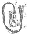
- FIG. 9is a perspective view of an optical fiber splitter/splice tray having a plurality of connectorized pigtails according to some embodiments of the present invention.
- FIG. 10is a perspective view of an optical fiber splitter/splice box having a plurality of connectorized pigtails according to some embodiments of the present invention.
- FIG. 11is a flowchart illustrating methods for outside plant management of subscriber optical fiber connectivity according to some embodiments of the present invention.
- Some embodiments of the present inventionutilize a multi-layer, fold down tray approach to support various functions, such as slack storage, pigtail to outside plant (OSP) cable splicing and angle down front patching.
- a termination modulemay be designed in a modular fashion so that it can be used separately in a small pedestal or ganged together with other termination modules in a pad (i.e. ground) or pole mounted cabinet.
- the termination modulesmay also be pre-terminated to subscriber location optical fibers before mounting in an interconnect cabinet.
- the termination modulesin some embodiments may also be removed from the cabinet and carried to a remote location, such as a splice truck, to facilitate initial installation.
- the termination modulesin some embodiments include splice trays therein that may be oriented such that they can be worked on remotely or in the cabinet when a repair situation arises.
- the entire patching fieldpivots downward and/or sideways, allowing access to both sides of the connector for cleaning while potentially reducing or avoiding the normal disruption of disconnecting existing subscribers to gain access. Cleaning both sides of an optical connector may be beneficial, particularly when using connectors in the OSP.
- a detachable cable security memberis incorporated into some embodiments of the termination module of the present invention, which may allow fixation of the cable as well as the central strength member in both an open and closed position of the termination module without placing undue strain on the cable from a change in orientation of the termination module during installation or the like.
- the cable security member of some embodiments of the present inventionneed only be separated from the termination module during closing (when the termination panel is moved from an open to a closed position).
- the relative position of the cable security member to the splice traysmay remain substantially unchanged during the closing (or opening).
- a splitter module array(one or more splitters) can be built up incrementally in a cabinet by adding one pre-connectorized splitter module at a time in some embodiments of the present invention.
- the splitter modulemay, for example, be splitter/splice trays coupled to a hanger bracket for purposes of mounting.
- alternative embodimentsmay use a splitter box that is loaded into a rack or some other bracket.
- Labels on the forward facing edge of the splitter modulemay be included to indicate subscribers allocated to that splitter. Labels on the front of the splitter module could also be included to indicate test data and/or relevant manufacturing information.
- random over-length storage of connectorized pigtails exiting the splittersmay incorporate the use of half-moon spools, which may provide bend control as well as incremental slack compensation.
- the spoolsmay be, for example, evenly spaced such that each spool is allocated to specific fields of the patch panel, which may simplify tracing of pigtails.
- shifting the bulkhead connection point from the splitter to a patch panelmay permit access to both sides of the connection point for cleaning.
- a reduced number of loose/unterminated pigtailsmay need to be managed during routine maintenance and reconfiguration.
- Various embodiments of the present inventionmay provide for 216 or more pigtails hanging in bunches and that number may be incrementally reduced as subscribers are added to the network.
- Some embodiments of the present inventionmay reduce this congestion to a maximum of 15 fibers for 1 ⁇ 16 splitters or 31 for 1 ⁇ 32 splitters. This smaller number may be reduced as subscribers are added until none are left and a new splitter is added.
- the unused pigtailsmay be stored on the side of the cabinet segregated from the active fibers.
- the patch panel designmay allow subscribers to be identified quickly as contrasted with other known approaches that require the craft to fumble through bundles of pigtails in search of one specific customer that has subscribed to the network and needs connecting.
- FIG. 1is a schematic diagram illustrating an interconnect cabinet 100 for optical fibers according to some embodiments of the present invention.
- the interconnect cabinet 100is used for connecting subscriber cable(s) 105 with the central office outside plant (OSP) cable(s) 110 so as to manage connectivity of subscriber locations to the central office.
- the interconnect cabinet 100includes splice modules 115 a, 115 b, a termination module 130 having a front face that provides a patch panel, a splitter module 140 and connectorized pigtails 150 a, 150 b.
- the splice modules 115 a, 115 bmay be used to connect optical fibers from the cables 105 , 110 to a backside of the optical fiber connection points (members) 120 a, 120 b. While two splice modules 115 a, 115 b are illustrated in FIG. 1 , more splice modules may be used depending upon the number of fibers to be routed through the interconnection cabinet 100 . Furthermore, although a separate splice module 115 b is shown for use with the central office cable 110 , in various embodiments of the present invention, a common splice module may be used for both the cable fibers of the subscriber 105 and the central office 110 .
- splice modules for making such interconnectionsprovide benefits in routing and control of radius of curvature and the like of optical fibers, it will understood that the present invention, in some embodiments, encompasses other methods of interconnect between the subscriber and central office cables 105 , 110 and the fiber connection points 120 a and 120 b.
- the splitter module 140has a connectorized pigtail 150 a extending to a fiber connection point 120 b to optically couple to a fiber from the central office.
- the fiber from the central officeis connected by the splitter module 140 to the plurality of connectorized pigtails 150 b.
- each of the connectorized pigtails 150 bare associated with an optical fiber feeder cable 110 coupled to a central office, typically through an individual fiber.
- the splitter module 140may be a 4 to 1, 16 to 1, 32 to 1 or the like splitter module based on the desired number of subscribers to be carried and supported by a single fiber feed to the central office.
- ones of the fibers from the subscriber cable 105 associated with different subscriber locationsare each coupled to respective ones of the fiber connection points 120 b in the patch panel front face of the termination module 130 .
- the connectorized pigtails 150 bhave a cable length sufficient to allow connection of each of the pigtails 150 b to the plurality of connection points 120 b.
- service to an individual subscriber locationmay be readily provided or ended by coupling or decoupling one of the connectorized pigtails 150 b from the one of the fiber connection points 120 b associated with that subscriber. Therefore, providing a readily determined location on the front patch panel of the termination module 130 associated with each specific subscriber may simplify the task of making a connection for a field technician who might otherwise have difficulty locating a pigtail 150 b associated with a specific subscriber.
- the fiber feed to the central office from the central office cable(s) 110is coupled through a splice module 115 b to an interconnection point 120 b on the patch panel front face of the termination module 130 . While shown as a separate connection points 120 a, 120 b in FIG. 1 , it will understood that any of the connection points 120 b could likewise be used to provide an interconnection to the central office cable(s) 110 .
- the input optical fiber to the splitter module 140is spliced to a fiber in the central office cable(s) 110 directly without use of the termination module 130 and the connectorized pigtail 150 a.
- the input optical fiber to the splitter module 140could be coupled to a fiber from the central office cable(s) in the splice module 115 b.
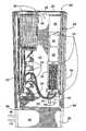
- the interconnect cabinet 200includes an enclosure 202 having an upper chamber 210 and a lower chamber 205 .
- the enclosure 202may be a double-walled housing configured to provide passive cooling for the cabinet 200 .
- the subscriber and central office cables 105 , 100are received in the lower chamber 205 , which is protected by a front cover panel 207 .
- the cables 105 , 100feed through a bottom panel 252 positioned between the upper chamber 210 and the lower chamber 205 through grommets 254 .
- the upper chamber 210may be provided a cleaner or more environmentally controlled environment than the lower chamber 205 .
- various embodiments of the present inventionmay provide for direct routing of the cables 105 and 110 into the upper chamber 210 of a single chamber enclosure not having a separate lower chamber.
- a termination module 230As shown in the embodiments of FIG. 2 , a termination module 230 , a plurality of splitter modules 240 having connectorized pigtails 250 and a plurality of spools 270 , 272 are positioned in the upper chamber 210 of the housing 202 .
- the termination module 230is removably mounted to a back wall 212 of the upper chamber 210 .
- the splitter modules 240are removably mounted to the back wall 212 by brackets 242 .
- the termination module 230includes a termination patch panel 232 on its front face that includes a plurality of optical fiber connection points (members) 220 .
- the connection members 220include sockets 221 configured to receive the connectorized plugs of the pigtails 250 .
- the termination patch panel 232may be modified based on the number of optical fibers to be connected by adding additional rows of connection members 220 in the regions 222 .
- Three brackets 234are shown on the termination module 230 that may be used to rest on a table or other flat surface when the termination panel 232 is rotated open to allow access to a backside of the connection member 220 .
- FIG. 2may allow for front panel access to the various connectivity components for arranging connections to subscriber locations.
- front side access to the cabinet 200is provided by opening of the rotatable door panels 260 defining the front panel of the interconnect cabinet 200 .
- a single panel door, removable panel or the likecould also be provided to allow front side access to the chamber 210 .
- the spooling system 270 , 272may be used to support routing of the pigtails 250 in a manner that may advantageously control bending of the pigtails 250 to reduce the risk of damage to the optical fiber and provide further organization to the routing of the pigtails 250 , particularly where a fully loaded interconnect cabinet 200 may include a large number of such pigtails 250 .
- the spooling system 270 , 272is mounted in the enclosure 202 and configured to receive and store excess cable length of the connectorized pigtails 250 .
- the spools 270in some embodiments of the present invention, are displaced from each other in the enclosure by a distance corresponding to a distance between a first and last row of the connection points 220 on the termination patch panel 232 . In other words, as viewed in FIG. 2 , a distance from a bottom to a top one of the spools 270 may correspond to a distance from a bottom to a top row of the interconnection members 220 .
- the spooling system 270 , 272may include an initial loop spool 272 configured to receive all the connectorized pigtails 250 and provide the connectorized pigtails a common entry point to the spools 270 .
- all of the pigtails 250may first be routed underneath the initial loop spool 272 and then over a selected one of the spools 270 based on the relative distance from the bottom panel 252 of an associated row of the connection members 220 to which the pigtail 250 is to be routed.
- the half-moon spools illustrated in FIG. 2may have a radius selected to provide the desired protection against damage due to bending of fibers in the pigtails 250 .
- the connectorized pigtails 250 in some embodiments of the present inventionare provided with substantially the same length. Use of selected ones of the spools 270 in routing may provide for occupying more or less unused length of such pigtails 250 based on which connection member row the pigtail 250 is routed to on the termination panel 232 .
- a plurality of splitter modules 240 and a single termination module 230are illustrated in FIG. 2 . However, as seen by the space between the splitters 240 and the termination module 230 , a plurality of termination modules 230 may be selectively mounted in the enclosure 202 in some embodiments of the present invention.
- FIG. 3is a front perspective view further illustrating some embodiments of the present invention.
- FIG. 3illustrates the interconnect cabinet of FIG. 2 with only one installed splitter module 240 and a second splitter module 240 in the process of being installed.
- the splitter modules 240are splitter trays having hanger brackets 344 attached thereto.
- the hanger brackets 344engage the brackets 242 to mount the splitter trays 240 in the interconnect cabinet 200 .
- a hook 305 in a sidewall of the enclosure 202that may be used to hang unused pigtails 250 .
- the hook 305in some embodiments of the present invention may be a spool, such as a half-moon spool.
- Some embodiments of the present inventionprovide for routing of jumper cables to provide a cross-connect between two of the interconnection members 220 , as contrasted with routing of pigtails 250 from the splitter modules 240 .
- the hook or mid-point spool 305may be used and positioned at a location above the spools 270 to facilitate routing of the jumper cables.
- the hook or mid-point spool 305could be positioned to provide a turn-around point at the mid-point of the jumper cable length.
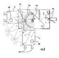
- FIG. 4is a perspective view of a termination module 430 according to some embodiments of the present invention with a termination panel 430 a (the front face of which defines a patch panel) in an open position.
- the termination panel 430 amay be moved to the illustrated open position by rotation about a pivot point 476 so as to allow access from the front of the interconnect cabinet 400 to a backside 420 ′ of the interconnection members 220 mounted in the patch panel 432 of the termination panel 430 a.
- the backside interconnection points 420 ′ in the embodiments of FIG. 4include sockets 421 configured to receive connectorized pigtails 480 extending from a splice module 115 a, 115 b coupled to the subscriber and/or central office cables 105 , 110 .
- the pigtail 480may extend from a splice chamber 430 b by, for example, routing through a protective conduit 472 b or a hardened cable 472 b.
- the cables 472 a, 472 bmay extend from splice modules 115 a, 115 b mounted in the splice chamber 430 b through an optical fiber slack receiving region 474 of the splice chamber 430 b.
- the splice chamber 430 bmay also be pivotally mounted in a manner such that access to the splice region from the front side of the interconnect cabinet 400 is provided via rotation of the splice chamber 430 b about a pivot point 478 .
- a mounting member 430 c of the termination module 430 bmay support the pivot points 476 , 478 and provide for mounting of the termination module 430 in the interconnect cabinet 400 .
- FIG. 4Also visible in FIG. 4 are the backside 470 of the patch panel 432 , brackets 434 and half-moon spools 470 , 472 .
- the arrangements of the spools 470 , 472differs from that described with reference to the spools 270 , 272 of FIG. 2 in that the lower initial loop spool 472 is aligned with the plurality of spools 470 rather than being offset toward the left side of the cabinet 200 as illustrated in FIG. 2 .
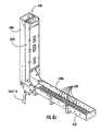
- FIG. 5is a front perspective view of an interconnect cabinet 500 for optical fibers according to some embodiments of the present invention showing installation of a termination module 530 in the cabinet 500 .
- the termination module 530may be manually removed with the cables 105 , 110 connected thereto by passing excess length of the cables 105 , 110 through the grommets 254 .
- Such excess cable lengthmay be stored in the lower chamber of the cabinet 500 or may be drawn from outside the cabinet 500 at a time when a technician removes the termination module 530 from the cabinet 500 .
- the termination module 530includes a termination panel 530 a, a splice chamber 530 b and a mounting member 530 c.
- the respective elements 530 a, 530 b, 530 cmay operate substantially the same as described in FIG. 4 with reference to like numbered elements ( 430 a, 430 b, 430 c).
- FIG. 6ais a perspective view of the termination module 630 in a closed position.
- FIG. 6bis a perspective view of the termination module 630 of FIG. 6a in a first open position showing a splice chamber 630 b and trays 615 .
- FIG. 6cis a perspective view of the termination module 630 of FIG. 6a in a second open position showing the backside of a termination panel 630 a.
- the termination module 630includes the termination panel 630 a, a splice chamber 630 b, and a mounting member 630 c.
- the termination panel 630 a and splice chamber 630 bare each rotatably mounted to the mounting member 630 c.
- a plurality of brackets 634are positioned on the termination panel 630 a so as to provide means for resting the termination module 630 on a table or other flat surface in the open position orientation of FIG. 6b or FIG. 6c to facilitate work on splices and the like by a technician setting up the termination module 630 while reducing the risk of damage to the interconnection members 620 .
- a movable cable securing member 682is configured to receive, secure and/or provide strain relief for an optical fiber cable 105 , 110 .
- the moveable cable securing member 682is illustrated in a first position aligned with a closed position of the termination panel 630 a and a splice chamber 630 b in FIG. 6a and a second position aligned with an open position of the termination panel 630 a and splice chamber 630 b in FIG. 6b .
- the moveable cable securing member 682 in FIGS. 6a , 6 b and 6 bis mounted so as to align with the splice chamber 630 and splice modules 615 in each position to reduce the risk of damage due to bending of the optical fiber cables 105 , 110 .
- FIG. 6aillustrates an arrangement and orientation suitable for use when installed in an interconnect cabinet allowing access to the front side of the interconnection members 620 .
- FIG. 6cillustrates allowing access to the backside 620 ′ of the interconnect members 620 .
- FIG. 6billustrates a position suitable for use during set up of the termination module 630 by a technician providing splices to fibers of the cables 105 , 110 using the splice modules 615 .
- temporary brackets 686may be provided to hold the cable securing member 682 in the second position aligned with the opened splice chamber 630 b.
- an attachment member 688is provided that is configured to receive and retain a strength member of an optical fiber cable 105 , 110 .
- the attachment member 688is a bolt, which may couple to a retaining member, such as a bracket or clamp, positioned on an opposite face of the cable securing member 682 .
- further supportmay be provided by attaching the outer jacket of the cable 105 , 110 with a hose clamp, twist tie or the like to the tie off tabs 684 .
- the illustrated cable securing member 682 in FIG. 6bincludes two flat plate members, each of which may be configured to receive two cables 105 , 110 . It is to be understood that other attachment members may be provided using various securing or clamping devices suitable for securely grasping a strength member of a cable and that one or more such attachment members may be provided for use with each cable secured by the cable securing member 682 .
- the termination panel 630 a and splice chamber 630 bare pivotably mounted to the mounting member 630 c for independent pivotal movement.
- the mounting member 630 cis configured for mounting in an interconnect cabinet 200 , 300 , 400 , 500 using for example, the mounting holes 631 illustrated in FIG. 6b .
- the cable securing member 682Before opening the termination module 630 from the position of FIG. 6a to the position of FIG. 6b , the cable securing member 682 may be detached from the mounting member 630 c. The termination panel 630 a and splice chamber 630 b may then be pivoted to the open position of FIG. 6b and the cable securing member 682 may be secured into the position shown in FIG. 6b using the brackets 686 . When operations related to splicing and the like are completed, a technician may remove the cable securing member 688 and the brackets 686 and reattach the cable securing member 682 as shown in FIG.
- FIG. 6ashows the front side of the interconnection members 620 accessible on the patch panel 632 while FIG. 6c shows access to the backside 620 ′ of the interconnection members.
- FIG. 6bshows additional details of the splice chamber 630 b.
- the splice modules 615are pivotally mounted to respective angle mounting brackets 617 to provide access to different ones of the stacked plurality of splitter modules 615 .
- an excess length of respective optical fibersmay be provided for future use and/or modification in the optical fiber slack receiving region 674 .
- the optical fiber slack receiving region 674 illustrated in FIG. 6bis positioned between the splice modules 615 and the termination panel 630 a.
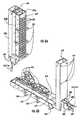
- FIG. 7ais a side view of a termination module 730 according to further embodiments of the present invention.
- FIG. 7bis a front perspective view of the termination module 730 of FIG. 7a .
- the termination module 730includes a termination panel 730 a, a splice chamber 730 b and a mounting member 730 c.
- a region for a plurality of interconnection members 720are provided in the patch panel 732 defined by the front face of the termination panel 730 . None of the interconnection points are mounted in the patch panel 732 as illustrated in FIG. 7b .
- the patch panel 732includes angled strips 796 configured to receive a plurality of interconnection members. The downward angle orientation illustrated for the strips 796 may provide improved safety for the installer by reducing the risk of light being directly aimed at the installer's eyes and/or may provide reduced infiltration of dirt and the like to the interconnection members 720 due to gravity.
- FIG. 7bThe arrangement for positioning of the interconnection members 720 in FIG. 7b differs from that described previously with reference to FIG. 6a primarily in the provision of a staggered alignment for rows of the interconnection members 720 . Such an arrangement may provide for improved accessibility of the interconnection members 720 , as the cascading of pigtails feeding to the interconnection members 720 may less heavily overlay lower position interconnection member rows in the patch panel 732 .
- FIGS. 7b and 7bfurther illustrate angled mounting brackets 717 for use in pivotally mounting splice modules, such as optical splice trays, in a stacked relationship.
- FIGS. 7a and 7bfurther differ from those described with reference to FIGS. 6a-6c in the particulars of the moveable cable securing member 782 .
- the cable securing member 782is pivotable between a first position A aligned with a closed position of the termination panel 730 a and splice chamber 730 b and a second position B aligned with an open position of the termination panel 730 a and the splice chamber 730 b.
- An attachment member 688 and tie-off tab 784may be provided for securing a respective optical fiber cable as described previously with reference to the similarly numbered elements of FIGS. 6a-6c ( 684 , 688 ).
- the cable securing member 688is pivotally attached to the termination module 730 at a pivot point 790 to allow movement between the first position A and the second position B.
- the cable securing member 788is configured, in some embodiments of the present invention, to pivot about a neutral axis having an arc length for a cable secured therein that is substantially the same in the first position A and the second position B to limit load on the cable secured therein during movement of the cable securing member 788 between the first position A and the second position B.
- a movement track 792is provided including a securing member or bolt 794 for locking the cable securing member 782 in a desired position.
- FIG. 9is a perspective view of an optical fiber splitter/splice tray 940 having a plurality of connectorized pigtails 950 according to some embodiments of the present invention.
- a mounting bracket 944is mounted at one end of the optical fiber splitter/splice tray 940 and the pigtails 950 extend from an opposite end thereof.
- Connector plugs 951are provided at the ends of the connectorized pigtails 950 .
- FIG. 10is a perspective view illustrating an alternative optical splitter module arrangement using a splitter box 1040 having connectorized pigtails 1050 extending therefrom, rather than an optical fiber tray.
- the splitter box 1040like the splitter tray 940 , may be held in place in an interconnect cabinet by, for example, tabs and/or a bracket.
- FIG. 11operations begin at Block 1100 by providing a termination panel in an interconnect cabinet for optical fibers including a plurality of optical fiber connection points (connection members) and a splitter in the cabinet having a plurality of optic fiber connectorized pigtails extending therefrom.
- a termination panel, splitter and cabinet arrangementhas been described previously with reference to FIGS. 1-10 .
- the connectorized pigtailsmay have a cable length sufficient to allow connection to the plurality of connection points.
- the connectorized pigtailsare optically spliced to an optical fiber feeder cable coupled to a central office (Block 1105 ).
- the plurality of optical fiber connection points (or connection members)are optically spliced to receptive subscriber locations (Block 1110 ).
- ones of the connectorized pigtailsare routed around selected ones of a plurality of fiber management spools based on a location of the connection points to which they are to be coupled (Block 1115 ).
- Ones of the connectorized pigtailsare selectively coupled to ones of the connection points to provide service to the designated ones of the subscriber locations (Block 1120 ).
- ones of the connectorized pigtailsmay be selectively decoupled from one of the connection points to terminate service for a designated one of the subscriber locations.
- FIG. 1 and the flowchart of FIG. 11illustrate the architecture, functionality, and operation of possible implementations of methods for outside plant management of subscriber optical fiber connectivity according to some embodiments of the present invention. It should be noted that, in some alternative implementations, the acts noted in the blocks may occur out of the order noted in the figures. For example, two blocks shown in succession may, in fact, be executed substantially concurrently, or the blocks may be executed in the reverse order, depending upon the functionality involved.
Landscapes
- Physics & Mathematics (AREA)
- General Physics & Mathematics (AREA)
- Optics & Photonics (AREA)
- Light Guides In General And Applications Therefor (AREA)
- Mechanical Coupling Of Light Guides (AREA)
- Optical Couplings Of Light Guides (AREA)
Abstract
Description
Claims (21)
Priority Applications (3)
| Application Number | Priority Date | Filing Date | Title |
|---|---|---|---|
| US12/592,274USRE44758E1 (en) | 2003-03-20 | 2009-11-20 | Optical fiber interconnect cabinets, termination modules and fiber connectivity management for the same |
| US14/178,135USRE46945E1 (en) | 2003-03-20 | 2014-02-11 | Optical fiber interconnect cabinets, termination modules and fiber connectivity management for the same |
| US16/030,471USRE48675E1 (en) | 2003-03-20 | 2018-07-09 | Optical fiber interconnect cabinets, termination modules and fiber connectivity management for the same |
Applications Claiming Priority (4)
| Application Number | Priority Date | Filing Date | Title |
|---|---|---|---|
| US45632303P | 2003-03-20 | 2003-03-20 | |
| US10/799,328US7142764B2 (en) | 2003-03-20 | 2004-03-12 | Optical fiber interconnect cabinets, termination modules and fiber connectivity management for the same |
| US11/584,068US7298952B2 (en) | 2003-03-20 | 2006-10-20 | Optical fiber interconnect cabinets, termination modules and fiber connectivity management for the same |
| US12/592,274USRE44758E1 (en) | 2003-03-20 | 2009-11-20 | Optical fiber interconnect cabinets, termination modules and fiber connectivity management for the same |
Related Parent Applications (1)
| Application Number | Title | Priority Date | Filing Date |
|---|---|---|---|
| US11/584,068ReissueUS7298952B2 (en) | 2003-03-20 | 2006-10-20 | Optical fiber interconnect cabinets, termination modules and fiber connectivity management for the same |
Related Child Applications (2)
| Application Number | Title | Priority Date | Filing Date |
|---|---|---|---|
| US11/584,068ContinuationUS7298952B2 (en) | 2003-03-20 | 2006-10-20 | Optical fiber interconnect cabinets, termination modules and fiber connectivity management for the same |
| US14/178,135ContinuationUSRE46945E1 (en) | 2003-03-20 | 2014-02-11 | Optical fiber interconnect cabinets, termination modules and fiber connectivity management for the same |
Publications (1)
| Publication Number | Publication Date |
|---|---|
| USRE44758E1true USRE44758E1 (en) | 2014-02-11 |
Family
ID=33101238
Family Applications (5)
| Application Number | Title | Priority Date | Filing Date |
|---|---|---|---|
| US10/799,328Expired - LifetimeUS7142764B2 (en) | 2003-03-20 | 2004-03-12 | Optical fiber interconnect cabinets, termination modules and fiber connectivity management for the same |
| US11/584,068CeasedUS7298952B2 (en) | 2003-03-20 | 2006-10-20 | Optical fiber interconnect cabinets, termination modules and fiber connectivity management for the same |
| US12/592,274Expired - LifetimeUSRE44758E1 (en) | 2003-03-20 | 2009-11-20 | Optical fiber interconnect cabinets, termination modules and fiber connectivity management for the same |
| US14/178,135Expired - LifetimeUSRE46945E1 (en) | 2003-03-20 | 2014-02-11 | Optical fiber interconnect cabinets, termination modules and fiber connectivity management for the same |
| US16/030,471Expired - LifetimeUSRE48675E1 (en) | 2003-03-20 | 2018-07-09 | Optical fiber interconnect cabinets, termination modules and fiber connectivity management for the same |
Family Applications Before (2)
| Application Number | Title | Priority Date | Filing Date |
|---|---|---|---|
| US10/799,328Expired - LifetimeUS7142764B2 (en) | 2003-03-20 | 2004-03-12 | Optical fiber interconnect cabinets, termination modules and fiber connectivity management for the same |
| US11/584,068CeasedUS7298952B2 (en) | 2003-03-20 | 2006-10-20 | Optical fiber interconnect cabinets, termination modules and fiber connectivity management for the same |
Family Applications After (2)
| Application Number | Title | Priority Date | Filing Date |
|---|---|---|---|
| US14/178,135Expired - LifetimeUSRE46945E1 (en) | 2003-03-20 | 2014-02-11 | Optical fiber interconnect cabinets, termination modules and fiber connectivity management for the same |
| US16/030,471Expired - LifetimeUSRE48675E1 (en) | 2003-03-20 | 2018-07-09 | Optical fiber interconnect cabinets, termination modules and fiber connectivity management for the same |
Country Status (8)
| Country | Link |
|---|---|
| US (5) | US7142764B2 (en) |
| EP (3) | EP2261712A3 (en) |
| JP (1) | JP2006520930A (en) |
| AT (1) | ATE530938T1 (en) |
| CA (1) | CA2519596A1 (en) |
| ES (1) | ES2372817T3 (en) |
| TW (1) | TWI343490B (en) |
| WO (1) | WO2004086112A1 (en) |
Cited By (3)
| Publication number | Priority date | Publication date | Assignee | Title |
|---|---|---|---|---|
| US20130105616A1 (en)* | 2011-10-28 | 2013-05-02 | Chun-Yuan Chang | Cable tidying device |
| USRE46945E1 (en) | 2003-03-20 | 2018-07-10 | Commscope Technologies Llc | Optical fiber interconnect cabinets, termination modules and fiber connectivity management for the same |
| US12276857B2 (en) | 2019-10-07 | 2025-04-15 | Commscope Technologies Llc | Fiber distribution hub including sealed splice module |
Families Citing this family (195)
| Publication number | Priority date | Publication date | Assignee | Title |
|---|---|---|---|---|
| US5883995A (en) | 1997-05-20 | 1999-03-16 | Adc Telecommunications, Inc. | Fiber connector and adapter |
| US6760531B1 (en) | 1999-03-01 | 2004-07-06 | Adc Telecommunications, Inc. | Optical fiber distribution frame with outside plant enclosure |
| CN1398232A (en)* | 2000-02-07 | 2003-02-19 | 特赫鲁赫鲁器材有限公司 | Portable-pente ski tow |
| US7198409B2 (en) | 2003-06-30 | 2007-04-03 | Adc Telecommunications, Inc. | Fiber optic connector holder and method |
| US7233731B2 (en) | 2003-07-02 | 2007-06-19 | Adc Telecommunications, Inc. | Telecommunications connection cabinet |
| SE526483C2 (en)* | 2003-09-05 | 2005-09-20 | Ericsson Telefon Ab L M | Method and apparatus for minimizing excess fiber cable |
| US6885798B2 (en) | 2003-09-08 | 2005-04-26 | Adc Telecommunications, Inc. | Fiber optic cable and furcation module |
| US6983095B2 (en) | 2003-11-17 | 2006-01-03 | Fiber Optic Network Solutions Corporation | Systems and methods for managing optical fibers and components within an enclosure in an optical communications network |
| US7369741B2 (en) | 2003-11-17 | 2008-05-06 | Fiber Optics Network Solutions Corp. | Storage adapter with dust cap posts |
| US6926449B1 (en)* | 2004-02-23 | 2005-08-09 | Corning Cable Systems Llc | Connector port for network interface device |
| US20050254757A1 (en)* | 2004-02-23 | 2005-11-17 | Ferretti Vincent E Iii | Connector port for network interface device |
| CA2558996A1 (en) | 2004-03-08 | 2005-09-22 | Adc Telecommunications, Inc. | Fiber access terminal |
| US7200315B2 (en)* | 2004-06-09 | 2007-04-03 | Nortel Networks Limited | Dynamic fiber slack management for telecom racks |
| US7218827B2 (en) | 2004-06-18 | 2007-05-15 | Adc Telecommunications, Inc. | Multi-position fiber optic connector holder and method |
| US7376322B2 (en) | 2004-11-03 | 2008-05-20 | Adc Telecommunications, Inc. | Fiber optic module and system including rear connectors |
| US7489849B2 (en) | 2004-11-03 | 2009-02-10 | Adc Telecommunications, Inc. | Fiber drop terminal |
| US20060158866A1 (en)* | 2005-01-20 | 2006-07-20 | Peterson Eric C | Electronic system cabinet having a lower panel with an opening to receive cables |
| US7260302B2 (en)* | 2005-02-16 | 2007-08-21 | Panduit Corp. | Patch cord management system |
| US7194181B2 (en) | 2005-03-31 | 2007-03-20 | Adc Telecommunications, Inc. | Adapter block including connector storage |
| US20060233507A1 (en)* | 2005-04-14 | 2006-10-19 | Elli Makrides-Saravanos | Methods and apparatus for splitter modules and splitter module housings |
| WO2006113810A2 (en)* | 2005-04-19 | 2006-10-26 | Adc Telecommunications, Inc. | Fiber breakout with integral connector |
| WO2006135524A2 (en)* | 2005-05-18 | 2006-12-21 | Corning Cable Systems Llc | High density optical fiber distribution enclosure |
| US7376323B2 (en)* | 2005-05-25 | 2008-05-20 | Adc Telecommunications, Inc. | Fiber optic adapter module |
| US7400813B2 (en) | 2005-05-25 | 2008-07-15 | Adc Telecommunications, Inc. | Fiber optic splitter module |
| US7636507B2 (en)* | 2005-06-17 | 2009-12-22 | Adc Telecommunications, Inc. | Compact blind mateable optical splitter |
| US20070003204A1 (en)* | 2005-06-30 | 2007-01-04 | Elli Makrides-Saravanos | Methods and apparatus for splitter modules and splitter module housings |
| US20070031100A1 (en)* | 2005-08-04 | 2007-02-08 | Garcia Cesar G | Optical fiber distribution cabinet |
| US7346254B2 (en)* | 2005-08-29 | 2008-03-18 | Adc Telecommunications, Inc. | Fiber optic splitter module with connector access |
| US7623749B2 (en) | 2005-08-30 | 2009-11-24 | Adc Telecommunications, Inc. | Fiber distribution hub with modular termination blocks |
| US7333706B2 (en)* | 2005-08-31 | 2008-02-19 | 3M Innovative Properties Company | Enclosure and organizer for telecommunication lines and splices |
| US20180067820A1 (en)* | 2005-09-30 | 2018-03-08 | International Business Machines Corporation | Method and system for using pre-existing connections in a dispersed storage network |
| US7245809B1 (en)* | 2005-12-28 | 2007-07-17 | Adc Telecommunications, Inc. | Splitter modules for fiber distribution hubs |
| US7418181B2 (en) | 2006-02-13 | 2008-08-26 | Adc Telecommunications, Inc. | Fiber optic splitter module |
| US7720343B2 (en) | 2006-02-13 | 2010-05-18 | Adc Telecommunications, Inc. | Fiber distribution hub with swing frame and modular termination panels |
| US7816602B2 (en)* | 2006-02-13 | 2010-10-19 | Adc Telecommunications, Inc. | Fiber distribution hub with outside accessible grounding terminals |
| US7760984B2 (en) | 2006-05-04 | 2010-07-20 | Adc Telecommunications, Inc. | Fiber distribution hub with swing frame and wrap-around doors |
| MX2009001629A (en)* | 2006-08-21 | 2009-02-23 | Afl Telecommunications Llc | Fiber distribution hub. |
| US7711234B2 (en) | 2006-10-02 | 2010-05-04 | Adc Telecommunications, Inc. | Reskinnable fiber distribution hub |
| US7583885B2 (en)* | 2006-11-28 | 2009-09-01 | Adc Telecommunications, Inc. | Fiber distribution enclosure |
| US7587115B1 (en) | 2006-11-30 | 2009-09-08 | Lockheed Martin Corporation | Integrated functionality in optical backplane |
| US7496268B2 (en) | 2006-12-13 | 2009-02-24 | Corning Cable Systems Llc | High density fiber optic hardware |
| US7519258B2 (en) | 2006-12-21 | 2009-04-14 | Corning Cable Systems Llc | Preconnectorized fiber optic local convergence points |
| US7349616B1 (en) | 2007-01-12 | 2008-03-25 | Corning Cable Systems Llc | Fiber optic local convergence points for multiple dwelling units |
| US7822310B2 (en) | 2007-02-28 | 2010-10-26 | Corning Cable Systems Llc | Fiber optic splice trays |
| US7558458B2 (en) | 2007-03-08 | 2009-07-07 | Adc Telecommunications, Inc. | Universal bracket for mounting a drop terminal |
| US7522805B2 (en)* | 2007-03-09 | 2009-04-21 | Adc Telecommunications, Inc. | Wall mount distribution arrangement |
| US7409138B1 (en)* | 2007-03-12 | 2008-08-05 | Corning Cable Systems Llc | Fiber optic local convergence points for multiple dwelling units |
| US7512304B2 (en) | 2007-03-23 | 2009-03-31 | Adc Telecommunications, Inc. | Drop terminal with anchor block for retaining a stub cable |
| US7715679B2 (en) | 2007-05-07 | 2010-05-11 | Adc Telecommunications, Inc. | Fiber optic enclosure with external cable spool |
| US7756379B2 (en) | 2007-08-06 | 2010-07-13 | Adc Telecommunications, Inc. | Fiber optic enclosure with internal cable spool |
| US8798427B2 (en) | 2007-09-05 | 2014-08-05 | Corning Cable Systems Llc | Fiber optic terminal assembly |
| EP2573602B1 (en)* | 2007-09-06 | 2014-07-09 | Prysmian S.p.A. | Modular system and methods for connecting an external communication network to a user network of a building |
| US8059932B2 (en)* | 2007-10-01 | 2011-11-15 | Clearfield, Inc. | Modular optical fiber cassette |
| US7945138B2 (en)* | 2007-10-01 | 2011-05-17 | Clearfield, Inc. | Modular optical fiber cassette |
| WO2009045396A2 (en)* | 2007-10-01 | 2009-04-09 | Clearfield, Inc. | Modular optical fiber cassettes and fiber management methods |
| EP2198328B1 (en) | 2007-10-09 | 2018-09-26 | ADC Telecommunications, INC. | Mini drop terminal |
| US7903923B2 (en) | 2007-10-09 | 2011-03-08 | Adc Telecommunications, Inc. | Drop terminal releasable engagement mechanism |
| US7536075B2 (en) | 2007-10-22 | 2009-05-19 | Adc Telecommunications, Inc. | Wavelength division multiplexing module |
| US7720344B2 (en)* | 2007-10-22 | 2010-05-18 | Adc Telecommunications, Inc. | Fiber distribution hub |
| US7885505B2 (en)* | 2007-10-22 | 2011-02-08 | Adc Telecommunications, Inc. | Wavelength division multiplexing module |
| US7751672B2 (en) | 2007-10-31 | 2010-07-06 | Adc Telecommunications, Inc. | Low profile fiber distribution hub |
| US7406242B1 (en) | 2007-11-16 | 2008-07-29 | Tyco Electronics Co., Ltd. | Interconnect enclosures for optical fibers including cross-connect modules and methods for using the same |
| US8229265B2 (en) | 2007-11-21 | 2012-07-24 | Adc Telecommunications, Inc. | Fiber distribution hub with multiple configurations |
| US8238709B2 (en) | 2007-12-18 | 2012-08-07 | Adc Telecommunications, Inc. | Multi-configuration mounting system for fiber distribution hub |
| WO2009089327A2 (en)* | 2008-01-09 | 2009-07-16 | Adc Telecommunications, Inc. | Wall box adapted to be mounted at a mid-span access location of a telecommunications cable |
| US8107816B2 (en) | 2008-01-29 | 2012-01-31 | Adc Telecommunications, Inc. | Wavelength division multiplexing module |
| US7715682B2 (en)* | 2008-03-04 | 2010-05-11 | Adc Telecommunications, Inc. | Fiber distribution hub having an adjustable plate |
| US7889961B2 (en) | 2008-03-27 | 2011-02-15 | Corning Cable Systems Llc | Compact, high-density adapter module, housing assembly and frame assembly for optical fiber telecommunications |
| US20090277681A1 (en)* | 2008-04-04 | 2009-11-12 | Musolf Bruce R | Expansion cross-connect enclosure |
| US9276673B2 (en) | 2008-04-24 | 2016-03-01 | Commscope Technologies Llc | Methods and systems for testing a fiber optic network |
| US8042699B2 (en)* | 2008-05-29 | 2011-10-25 | Commscope, Inc. Of North Carolina | Adjustable cable routing spool |
| US7676136B2 (en)* | 2008-06-26 | 2010-03-09 | Emerson Network Power, Energy Systems, North America, Inc. | Fiber distribution hubs with patch and splice enclosures |
| ES2560802T3 (en) | 2008-08-27 | 2016-02-22 | Adc Telecommunications, Inc. | Fiber optic adapter with integrally molded bushing alignment structure |
| US8452148B2 (en) | 2008-08-29 | 2013-05-28 | Corning Cable Systems Llc | Independently translatable modules and fiber optic equipment trays in fiber optic equipment |
| US11294136B2 (en) | 2008-08-29 | 2022-04-05 | Corning Optical Communications LLC | High density and bandwidth fiber optic apparatuses and related equipment and methods |
| CN102209921B (en)* | 2008-10-09 | 2015-11-25 | 康宁光缆系统有限公司 | There is the fibre-optic terminus supported from the adapter panel of the input and output optical fiber of optical splitters |
| US8879882B2 (en) | 2008-10-27 | 2014-11-04 | Corning Cable Systems Llc | Variably configurable and modular local convergence point |
| US8224144B2 (en) | 2008-10-31 | 2012-07-17 | Tyco Electronics Corporation | Fiber optic connector storage apparatus and methods for using the same |
| WO2010059623A1 (en) | 2008-11-21 | 2010-05-27 | Adc Telecommunications, Inc. | Fiber optic telecommunications module |
| CN102282495B (en)* | 2009-01-15 | 2015-04-22 | Adc电信公司 | Fiber optic module, chassis and adapter |
| US8380036B2 (en)* | 2009-01-20 | 2013-02-19 | Adc Telecommunications, Inc. | Splitter module with connectorized pigtail manager |
| EP2221932B1 (en) | 2009-02-24 | 2011-11-16 | CCS Technology Inc. | Holding device for a cable or an assembly for use with a cable |
| EP2237091A1 (en) | 2009-03-31 | 2010-10-06 | Corning Cable Systems LLC | Removably mountable fiber optic terminal |
| US8699838B2 (en) | 2009-05-14 | 2014-04-15 | Ccs Technology, Inc. | Fiber optic furcation module |
| US9075216B2 (en) | 2009-05-21 | 2015-07-07 | Corning Cable Systems Llc | Fiber optic housings configured to accommodate fiber optic modules/cassettes and fiber optic panels, and related components and methods |
| US8538226B2 (en) | 2009-05-21 | 2013-09-17 | Corning Cable Systems Llc | Fiber optic equipment guides and rails configured with stopping position(s), and related equipment and methods |
| JP5271824B2 (en)* | 2009-06-16 | 2013-08-21 | 日本電信電話株式会社 | Optical jumper unit |
| US8712206B2 (en) | 2009-06-19 | 2014-04-29 | Corning Cable Systems Llc | High-density fiber optic modules and module housings and related equipment |
| EP2443497B1 (en) | 2009-06-19 | 2020-03-04 | Corning Cable Systems LLC | High density and bandwidth fiber optic apparatus |
| WO2010148325A1 (en) | 2009-06-19 | 2010-12-23 | Corning Cable Systems Llc | High fiber optic cable packing density apparatus |
| JP5264633B2 (en)* | 2009-07-02 | 2013-08-14 | 株式会社フジクラ | Optical termination box |
| US8606067B2 (en)* | 2009-09-04 | 2013-12-10 | Adc Telecommunications, Inc. | Pedestal terminal with swing frame |
| US8467651B2 (en) | 2009-09-30 | 2013-06-18 | Ccs Technology Inc. | Fiber optic terminals configured to dispose a fiber optic connection panel(s) within an optical fiber perimeter and related methods |
| US8625950B2 (en) | 2009-12-18 | 2014-01-07 | Corning Cable Systems Llc | Rotary locking apparatus for fiber optic equipment trays and related methods |
| US8992099B2 (en) | 2010-02-04 | 2015-03-31 | Corning Cable Systems Llc | Optical interface cards, assemblies, and related methods, suited for installation and use in antenna system equipment |
| CN102870021B (en) | 2010-03-02 | 2015-03-11 | 蒂安电子服务有限责任公司 | Fibre-optic telecommunication module |
| US8649649B2 (en) | 2010-03-03 | 2014-02-11 | Adc Telecommunications, Inc. | Fiber distribution hub with connectorized stub cables |
| US9547144B2 (en) | 2010-03-16 | 2017-01-17 | Corning Optical Communications LLC | Fiber optic distribution network for multiple dwelling units |
| US20110235986A1 (en)* | 2010-03-24 | 2011-09-29 | Adc Telecommunications, Inc. | Optical fiber drawer with connectorized stub cable |
| US8913866B2 (en) | 2010-03-26 | 2014-12-16 | Corning Cable Systems Llc | Movable adapter panel |
| US8837940B2 (en)* | 2010-04-14 | 2014-09-16 | Adc Telecommunications, Inc. | Methods and systems for distributing fiber optic telecommunication services to local areas and for supporting distributed antenna systems |
| CA2796221C (en) | 2010-04-16 | 2018-02-13 | Ccs Technology, Inc. | Sealing and strain relief device for data cables |
| US8792767B2 (en) | 2010-04-16 | 2014-07-29 | Ccs Technology, Inc. | Distribution device |
| EP2381284B1 (en) | 2010-04-23 | 2014-12-31 | CCS Technology Inc. | Under floor fiber optic distribution device |
| US9239442B2 (en) | 2010-04-27 | 2016-01-19 | Adc Communications (Shanghai) Co., Ltd. | Fiber optic module and chassis |
| US9720195B2 (en) | 2010-04-30 | 2017-08-01 | Corning Optical Communications LLC | Apparatuses and related components and methods for attachment and release of fiber optic housings to and from an equipment rack |
| US8879881B2 (en) | 2010-04-30 | 2014-11-04 | Corning Cable Systems Llc | Rotatable routing guide and assembly |
| US9519118B2 (en) | 2010-04-30 | 2016-12-13 | Corning Optical Communications LLC | Removable fiber management sections for fiber optic housings, and related components and methods |
| US8660397B2 (en) | 2010-04-30 | 2014-02-25 | Corning Cable Systems Llc | Multi-layer module |
| US8705926B2 (en) | 2010-04-30 | 2014-04-22 | Corning Optical Communications LLC | Fiber optic housings having a removable top, and related components and methods |
| US9632270B2 (en) | 2010-04-30 | 2017-04-25 | Corning Optical Communications LLC | Fiber optic housings configured for tool-less assembly, and related components and methods |
| US9075217B2 (en) | 2010-04-30 | 2015-07-07 | Corning Cable Systems Llc | Apparatuses and related components and methods for expanding capacity of fiber optic housings |
| WO2011140461A2 (en) | 2010-05-07 | 2011-11-10 | Adc Telecommunications, Inc. | Fiber distribution hub with pass-through interfaces |
| CN110174737A (en) | 2010-06-23 | 2019-08-27 | Adc电信公司 | Telecommunication assembly |
| US8718436B2 (en) | 2010-08-30 | 2014-05-06 | Corning Cable Systems Llc | Methods, apparatuses for providing secure fiber optic connections |
| US8274782B2 (en)* | 2010-09-30 | 2012-09-25 | Rockwell Automation Technologies, Inc. | Motor control center network connectivity method and system |
| WO2012054454A2 (en)* | 2010-10-19 | 2012-04-26 | Corning Cable Systems Llc | Transition box for multiple dwelling unit fiber optic distribution network |
| US9279951B2 (en) | 2010-10-27 | 2016-03-08 | Corning Cable Systems Llc | Fiber optic module for limited space applications having a partially sealed module sub-assembly |
| WO2012058391A1 (en) | 2010-10-28 | 2012-05-03 | Corning Cable Systems Llc | Impact resistant fiber optic enclosures and related methods |
| US9116324B2 (en) | 2010-10-29 | 2015-08-25 | Corning Cable Systems Llc | Stacked fiber optic modules and fiber optic equipment configured to support stacked fiber optic modules |
| US8662760B2 (en) | 2010-10-29 | 2014-03-04 | Corning Cable Systems Llc | Fiber optic connector employing optical fiber guide member |
| US8494332B2 (en) | 2010-11-15 | 2013-07-23 | Adc Telecommunications, Inc. | Tray assembly for a fiber optic enclosure |
| CA2819235C (en) | 2010-11-30 | 2018-01-16 | Corning Cable Systems Llc | Fiber device holder and strain relief device |
| WO2012106510A2 (en) | 2011-02-02 | 2012-08-09 | Corning Cable Systems Llc | Dense fiber optic connector assemblies and related connectors and cables suitable for establishing optical connections for optical backplanes in equipment racks |
| US8687934B2 (en) | 2011-03-21 | 2014-04-01 | Tyco Electronics Corporation | Fiber optic component holders and enclosures and methods including the same |
| US8913868B2 (en) | 2011-03-28 | 2014-12-16 | Tyco Electronics Corporation | Fiber optic component tray |
| US9182563B2 (en) | 2011-03-31 | 2015-11-10 | Adc Telecommunications, Inc. | Adapter plate for fiber optic module |
| US9008485B2 (en) | 2011-05-09 | 2015-04-14 | Corning Cable Systems Llc | Attachment mechanisms employed to attach a rear housing section to a fiber optic housing, and related assemblies and methods |
| CA2877896C (en) | 2011-06-24 | 2020-07-21 | Adc Telecommunications, Inc. | Fiber termination enclosure with modular plate assemblies |
| AU2012275598A1 (en) | 2011-06-30 | 2014-01-16 | Corning Optical Communications LLC | Fiber optic equipment assemblies employing non-U-width-sized housings and related methods |
| US8953924B2 (en) | 2011-09-02 | 2015-02-10 | Corning Cable Systems Llc | Removable strain relief brackets for securing fiber optic cables and/or optical fibers to fiber optic equipment, and related assemblies and methods |
| WO2013033890A1 (en) | 2011-09-06 | 2013-03-14 | Adc Telecommunications, Inc. | Adapter for fiber optic module |
| US9417418B2 (en) | 2011-09-12 | 2016-08-16 | Commscope Technologies Llc | Flexible lensed optical interconnect device for signal distribution |
| RU2611105C2 (en) | 2011-10-07 | 2017-02-21 | Адс Телекоммьюникейшнз, Инк. | Fibre-optic cartridge, system and method |
| US9069151B2 (en) | 2011-10-26 | 2015-06-30 | Corning Cable Systems Llc | Composite cable breakout assembly |
| US9038832B2 (en) | 2011-11-30 | 2015-05-26 | Corning Cable Systems Llc | Adapter panel support assembly |
| US9219546B2 (en) | 2011-12-12 | 2015-12-22 | Corning Optical Communications LLC | Extremely high frequency (EHF) distributed antenna systems, and related components and methods |
| US10110307B2 (en) | 2012-03-02 | 2018-10-23 | Corning Optical Communications LLC | Optical network units (ONUs) for high bandwidth connectivity, and related components and methods |
| US9791653B2 (en)* | 2012-04-03 | 2017-10-17 | CommScope Connectivity Belgium BVBA | Telecommunications enclosure organizer |
| US8873926B2 (en) | 2012-04-26 | 2014-10-28 | Corning Cable Systems Llc | Fiber optic enclosures employing clamping assemblies for strain relief of cables, and related assemblies and methods |
| WO2013172072A1 (en)* | 2012-05-18 | 2013-11-21 | 日本電気株式会社 | Optical system, optical deveice, and optical connection method |
| US9004778B2 (en) | 2012-06-29 | 2015-04-14 | Corning Cable Systems Llc | Indexable optical fiber connectors and optical fiber connector arrays |
| US9250409B2 (en) | 2012-07-02 | 2016-02-02 | Corning Cable Systems Llc | Fiber-optic-module trays and drawers for fiber-optic equipment |
| WO2014011904A2 (en) | 2012-07-11 | 2014-01-16 | Adc Telecommunications, Inc. | Telecommunications cabinet modularization |
| US20140036442A1 (en)* | 2012-07-31 | 2014-02-06 | Alcatel-Lucent Deutschland Ag | Outdoor stackable telecommunications equipment cabinet family with flexible thermal and interface management and method of deploying the same |
| US9049500B2 (en) | 2012-08-31 | 2015-06-02 | Corning Cable Systems Llc | Fiber optic terminals, systems, and methods for network service management |
| US9146362B2 (en) | 2012-09-21 | 2015-09-29 | Adc Telecommunications, Inc. | Insertion and removal tool for a fiber optic ferrule alignment sleeve |
| US9146374B2 (en) | 2012-09-28 | 2015-09-29 | Adc Telecommunications, Inc. | Rapid deployment packaging for optical fiber |
| NZ706687A (en) | 2012-09-28 | 2017-09-29 | Adc Telecommunications Inc | Fiber optic cassette |
| US9223094B2 (en) | 2012-10-05 | 2015-12-29 | Tyco Electronics Nederland Bv | Flexible optical circuit, cassettes, and methods |
| US8909019B2 (en) | 2012-10-11 | 2014-12-09 | Ccs Technology, Inc. | System comprising a plurality of distribution devices and distribution device |
| ES2551077T3 (en) | 2012-10-26 | 2015-11-16 | Ccs Technology, Inc. | Fiber optic management unit and fiber optic distribution device |
| WO2014070511A1 (en)* | 2012-10-29 | 2014-05-08 | Adc Telecommunications, Inc. | System for testing passive optical lines |
| ES1141660Y (en) | 2012-12-19 | 2015-10-14 | Tyco Electronics Raychem Bvba | Distribution device with incrementally added dividers |
| US8985862B2 (en) | 2013-02-28 | 2015-03-24 | Corning Cable Systems Llc | High-density multi-fiber adapter housings |
| US9435975B2 (en) | 2013-03-15 | 2016-09-06 | Commscope Technologies Llc | Modular high density telecommunications frame and chassis system |
| NZ713567A (en)* | 2013-04-24 | 2018-11-30 | Prysmian Spa | User module and method for connecting an external communication network |
| CN103278902B (en)* | 2013-06-26 | 2015-04-15 | 江苏亨通光网科技有限公司 | Intensive FTTX optical cable splice box |
| WO2015126472A2 (en) | 2013-11-11 | 2015-08-27 | Adc Telecommunications, Inc. | Telecommunications module |
| WO2015116672A1 (en) | 2014-01-28 | 2015-08-06 | Adc Telecommunications, Inc. | Slidable fiber optic connection module with cable slack management |
| US9985723B2 (en) | 2014-02-04 | 2018-05-29 | CommScope Connectivity Belgium BVBA | Fiber optic cabinet and network system with back-up connectivity |
| US9494758B2 (en) | 2014-04-03 | 2016-11-15 | Commscope Technologies Llc | Fiber optic distribution system |
| AU2015276109B2 (en) | 2014-06-17 | 2020-11-19 | Adc Czech Republic, S.R.O. | Cable distribution system |
| WO2015200321A1 (en) | 2014-06-23 | 2015-12-30 | Adc Telecommunications, Inc. | Fiber cable fan-out assembly and method |
| GB2550531A (en) | 2014-07-25 | 2017-11-29 | Sabmiller Plc | Packaging |
| US10362710B2 (en) | 2014-10-01 | 2019-07-23 | American Products, L.L.C. | Below grade enclosure |
| US10054753B2 (en) | 2014-10-27 | 2018-08-21 | Commscope Technologies Llc | Fiber optic cable with flexible conduit |
| CA2968259C (en)* | 2014-11-20 | 2021-10-26 | Prysmian S.P.A. | Optical termination module, optical termination assembly with said optical termination module and electric cabinet with said optical termination module |
| US9885845B2 (en)* | 2015-01-15 | 2018-02-06 | Commscope, Inc. Of North Carolina | Module and assembly for fiber optic interconnections |
| US9494760B2 (en) | 2015-02-17 | 2016-11-15 | 3M Innovative Properties Company | Highly configurable fiber-optic interconnection tray |
| MX2017014377A (en) | 2015-05-15 | 2018-08-15 | Adc Telecommunications Shanghai Distrib Co Ltd | Alignment sleeve assembly and optical fibre adapter. |
| AU2015207954C1 (en) | 2015-07-31 | 2022-05-05 | Adc Communications (Australia) Pty Limited | Cable breakout assembly |
| WO2017034931A1 (en) | 2015-08-21 | 2017-03-02 | Commscope Technologies Llc | Telecommunications module |
| US10606009B2 (en) | 2015-12-01 | 2020-03-31 | CommScope Connectivity Belgium BVBA | Cable distribution system with fan out devices |
| EP3408701B1 (en) | 2016-01-28 | 2023-04-26 | CommScope Connectivity Belgium BVBA | Modular telecommunications enclosure |
| EP3403125B1 (en) | 2016-03-18 | 2021-07-14 | Commscope Technologies LLC | Fiber-optic cable fanout conduit arrangement and method for organizing optical fibers |
| US10222571B2 (en) | 2016-04-07 | 2019-03-05 | Commscope Technologies Llc | Telecommunications module and frame |
| US10215944B2 (en)* | 2016-06-30 | 2019-02-26 | Panduit Corp. | Modular fiber optic tray |
| WO2018039213A1 (en)* | 2016-08-22 | 2018-03-01 | Commscope Technologies Llc | Cabinet and patchcord management panel |
| US10890730B2 (en) | 2016-08-31 | 2021-01-12 | Commscope Technologies Llc | Fiber optic cable clamp and clamp assembly |
| US10606006B2 (en) | 2016-09-20 | 2020-03-31 | Clearfield, Inc. | Optical fiber distribution systems and components |
| US10859781B2 (en) | 2016-09-20 | 2020-12-08 | Clearfield, Inc. | Optical fiber distribution systems and components |
| EP3523687B1 (en)* | 2016-10-05 | 2023-09-27 | CommScope Connectivity Belgium BVBA | Telecommunications system and methods |
| US10914909B2 (en) | 2016-10-13 | 2021-02-09 | Commscope Technologies Llc | Fiber optic breakout transition assembly incorporating epoxy plug and cable strain relief |
| ES2929573T3 (en)* | 2017-02-23 | 2022-11-30 | Commscope Technologies Llc | High Fiber Count Termination Device |
| CN110622051A (en) | 2017-05-08 | 2019-12-27 | 康普技术有限责任公司 | Optical fiber branch transition assembly |
| US11409068B2 (en) | 2017-10-02 | 2022-08-09 | Commscope Technologies Llc | Fiber optic circuit and preparation method |
| CN109696732B (en) | 2017-10-24 | 2022-12-09 | 康普技术有限责任公司 | Fiber Management Device |
| DE202017107765U1 (en)* | 2017-12-20 | 2018-02-15 | Knürr GmbH | Electricity distribution |
| US12169318B2 (en)* | 2018-08-20 | 2024-12-17 | Commscope Technologies Llc | Telecommunications equipment frame |
| US11502493B2 (en)* | 2020-01-27 | 2022-11-15 | Justrite Manufacturing Company, L.L.C. | Double-walled cabinet with external electrical connections |
| CA3165116A1 (en) | 2020-01-29 | 2021-08-05 | David Lane | Terminal enclosure for a telecommunications system |
| WO2021180796A1 (en)* | 2020-03-10 | 2021-09-16 | CommScope Connectivity Belgium BV | Telecommunications system and methods |
| US12339511B2 (en) | 2020-03-31 | 2025-06-24 | Commscope Technologies Llc | Fiber optic cable management systems and methods |
| CA3237923A1 (en)* | 2021-11-10 | 2023-05-19 | Stefan DONCHEV | Rack mountable panel for optimizing slack storage and management of optical fiber cables |
Citations (203)
| Publication number | Priority date | Publication date | Assignee | Title |
|---|---|---|---|---|
| US4630886A (en) | 1984-04-16 | 1986-12-23 | At&T Bell Laboratories | Lightguide distributing unit |
| US4736100A (en) | 1986-07-31 | 1988-04-05 | Amp Incorporated | Optical loop attenuator simulating an optical system |
| US4747020A (en) | 1986-05-16 | 1988-05-24 | Adc Telecommunications, Inc. | Wire distribution apparatus |
| US4765710A (en) | 1985-07-30 | 1988-08-23 | Siemens Aktiengesellschaft | Distributing frame for optical waveguides and the like |
| JPS63229409A (en) | 1987-03-18 | 1988-09-26 | Matsushita Electric Ind Co Ltd | Light emitting/light receiving module |
| EP0293183A2 (en) | 1987-05-26 | 1988-11-30 | Minnesota Mining And Manufacturing Company | Optical fiber distribution panel |
| US4792203A (en) | 1985-09-17 | 1988-12-20 | Adc Telecommunications, Inc. | Optical fiber distribution apparatus |
| US4861134A (en) | 1988-06-29 | 1989-08-29 | American Telephone And Telegraph Company, At&T Bell Laboratories | Opto-electronic and optical fiber interface arrangement |
| EP0349290A1 (en) | 1988-06-29 | 1990-01-03 | BRITISH TELECOMMUNICATIONS public limited company | Patch panel |
| US4900123A (en) | 1988-08-29 | 1990-02-13 | Gte Products Corporation | 1550 nm fiber distribution panel |
| US4913522A (en) | 1984-04-11 | 1990-04-03 | Nv Raychem Sa | Electrofit fibre optics butt splice |
| US4948220A (en) | 1988-06-20 | 1990-08-14 | Societe Anonyme De Telecommunications | Module for distributing and connecting optical fibers |
| US4995688A (en) | 1989-07-31 | 1991-02-26 | Adc Telecommunications, Inc. | Optical fiber distribution frame |
| US5023646A (en) | 1985-12-27 | 1991-06-11 | Minolta Camera Kabushiki Kaisha | Automatic focus detection system |
| US5058983A (en) | 1990-07-06 | 1991-10-22 | Aster Corporation | Fiber optic connector terminator |
| US5073042A (en) | 1990-06-21 | 1991-12-17 | Amp Incorporated | Coupling bushing for various types of optical fiber connectors |
| US5076688A (en) | 1990-03-23 | 1991-12-31 | Amp Incorporated | Optical simulator with loop-back attenuator having metalized optical fiber |
| US5100221A (en) | 1990-01-22 | 1992-03-31 | Porta Systems Corp. | Optical fiber cable distribution frame and support |
| US5129030A (en) | 1991-05-30 | 1992-07-07 | At&T Bell Laboratories | Movable lightguide connector panel |
| US5142598A (en) | 1991-08-28 | 1992-08-25 | Porta Systems Corp. | Fiber optic connector having snap ring adjustment means |
| DE4207531A1 (en) | 1991-03-12 | 1992-09-24 | Reichle & De Massari Fa | Distributor-cabinet system e.g. for telephone signal transmission fibre glass cable - has cabinet formed from frame structure with internally linked individual pivot frame having superimposed assembly group bearers |
| US5179618A (en) | 1990-07-11 | 1993-01-12 | Adc Telecommunications, Inc. | Fiber optic connector module |
| US5214735A (en) | 1992-04-06 | 1993-05-25 | Adc Telecommunications, Inc. | Fiber optic connector retainer |
| US5233674A (en) | 1991-11-21 | 1993-08-03 | Methode Electronics, Inc. | Fiber optic connector with sliding tab release |
| US5274729A (en) | 1992-07-30 | 1993-12-28 | At&T Bell Laboratories | Universal optical fiber buildout system |
| US5274731A (en) | 1992-12-24 | 1993-12-28 | Adc Telecommunications, Inc. | Optical fiber cabinet |
| US5289558A (en) | 1991-10-05 | 1994-02-22 | Krone Aktiengesellshaft | Switching assembly for glass fiber cables of the telecommunication and data technology |
| EP0585809A1 (en) | 1992-08-26 | 1994-03-09 | Reichle + De-Massari AG Elektro-Ingenieure | Terminal splice assembly for telecommunication cable, particulary for optical assembly |
| DE4229510A1 (en) | 1992-09-04 | 1994-03-10 | Siemens Ag | Distribution box for optical fibre network - has central wiring region with plug panels and splicing region with distributor modules having pivoted cassette holders |
| US5317663A (en) | 1993-05-20 | 1994-05-31 | Adc Telecommunications, Inc. | One-piece SC adapter |
| US5333221A (en) | 1992-06-30 | 1994-07-26 | The Whitaker Corporation | Universal adapter for optical connectors |
| US5333222A (en) | 1993-05-14 | 1994-07-26 | Molex Incorporated | Adapter for interconnecting optical fiber connectors or the like |
| US5359688A (en) | 1994-03-04 | 1994-10-25 | Siecor Corporation | Metal internal holding clips for fiber optic connector coupling |
| US5363465A (en) | 1993-02-19 | 1994-11-08 | Adc Telecommunications, Inc. | Fiber optic connector module |
| US5367598A (en) | 1993-10-21 | 1994-11-22 | Nec America, Inc. | Interface chassis for fiber optic transport system |
| US5402515A (en) | 1994-03-01 | 1995-03-28 | Minnesota Mining And Manufacturing Company | Fiber distribution frame system, cabinets, trays and fiber optic connector couplings |
| US5408557A (en) | 1994-04-20 | 1995-04-18 | Hsu; Chung-Tang | FC-type optical fiber cable connector's adaptor |
| US5420958A (en) | 1990-05-21 | 1995-05-30 | Minnesota Mining And Manufacturing Company | Optical fiber distribution center |
| US5432875A (en) | 1993-02-19 | 1995-07-11 | Adc Telecommunications, Inc. | Fiber optic monitor module |
| WO1995020175A1 (en) | 1994-01-21 | 1995-07-27 | Adc Telecommunications, Inc. | High-density fiber distribution frame |
| US5442726A (en) | 1994-02-22 | 1995-08-15 | Hubbell Incorporated | Optical fiber storage system |
| US5448015A (en) | 1991-12-30 | 1995-09-05 | Societe Anonyme Dite Alcatel Cit | Support and Guide device for cables carrying elcetrical or light signals |
| US5469526A (en) | 1994-01-07 | 1995-11-21 | Porta Systems Corp. | Optical fiber support for printed circuit boards |
| EP0697610A1 (en) | 1994-08-15 | 1996-02-21 | PIRELLI GENERAL plc | Guiding optical fibres |
| US5506922A (en) | 1994-08-01 | 1996-04-09 | Molex Incorporated | Fiber optic component assembly with a movable protective shield |
| US5511144A (en) | 1994-06-13 | 1996-04-23 | Siecor Corporation | Optical distribution frame |
| US5542015A (en) | 1993-04-08 | 1996-07-30 | The Whitaker Corporation | Optical fiber connector latching mechanism |
| EP0743701A2 (en) | 1995-05-17 | 1996-11-20 | AT&T IPM Corp. | Insulation displacement contact including retention means |
| US5636138A (en) | 1992-12-29 | 1997-06-03 | Lucent Technologies Inc. | Jumper cable selection and routing system |
| US5640482A (en) | 1995-08-31 | 1997-06-17 | The Whitaker Corporation | Fiber optic cable management rack |
| US5647043A (en) | 1995-10-12 | 1997-07-08 | Lucent Technologies, Inc. | Unipartite jack receptacle |
| EP0788002A1 (en) | 1996-02-01 | 1997-08-06 | Molex Incorporated | Fiber optic connector receptacle with protective shutter |
| US5689604A (en) | 1996-09-09 | 1997-11-18 | Lucent Technologies Inc. | Fiber optic operations center |
| US5708751A (en) | 1996-04-24 | 1998-01-13 | Tii Industries, Inc. | Optical fiber enclosure system |
| US5715348A (en) | 1996-03-27 | 1998-02-03 | Next Level Communications | Fiber management system and method for routing optical fiber having a minimum bend radius |
| US5734776A (en) | 1996-08-28 | 1998-03-31 | Adc Telecommunications, Inc. | Outside plant cross-connect apparatus |
| US5758002A (en) | 1996-12-31 | 1998-05-26 | Siecor Corporation | Routing and storage apparatus for optical fibers |
| US5758003A (en) | 1996-03-15 | 1998-05-26 | Adc Telecommunications, Inc. | High density fiber management |
| US5764844A (en) | 1994-03-21 | 1998-06-09 | N.V. Raychem S.A. | Splice organizing apparatus |
| US5774245A (en) | 1996-07-08 | 1998-06-30 | Worldcom Network Services, Inc. | Optical cross-connect module |
| US5774612A (en) | 1995-08-02 | 1998-06-30 | Molex Incorporated | Adapted for interconnecting optical fiber connectors |
| US5778132A (en) | 1997-01-16 | 1998-07-07 | Ciena Corporation | Modular optical amplifier and cassette system |
| US5784515A (en) | 1995-01-23 | 1998-07-21 | Nippon Telegraph And Telephone Corporation | Optical fiber cross connection apparatus and method |
| US5825955A (en) | 1997-02-05 | 1998-10-20 | Molex Incorporated | Fiber optic diversion connector |
| US5823646A (en) | 1997-09-02 | 1998-10-20 | Siecor Corporation | Door assembly for optical hardware cabinet |
| US5825962A (en) | 1996-12-31 | 1998-10-20 | Siecor Corporation | Optical fiber splice housing |
| US5883995A (en) | 1997-05-20 | 1999-03-16 | Adc Telecommunications, Inc. | Fiber connector and adapter |
| US5903698A (en) | 1997-04-11 | 1999-05-11 | Wiltron Company | Fiber optic connection assembly |
| US5909526A (en) | 1998-04-08 | 1999-06-01 | Molex Incorporated | Fiber optic connector assembly |
| WO1999027404A1 (en) | 1997-11-20 | 1999-06-03 | Siemens Aktiengesellschaft | Device for guiding lines in communication systems |
| US5913006A (en) | 1997-11-25 | 1999-06-15 | Northern Telecom Limited | Fibre slack storage retractable panel and interface |
| US5930425A (en) | 1998-04-21 | 1999-07-27 | Lucent Technologies Inc. | High density coupling module |
| US5945633A (en) | 1996-05-23 | 1999-08-31 | The Siemon Company | Rack mountable cable distribution enclosure having an angled adapter plate bracket |
| US5956444A (en) | 1997-02-13 | 1999-09-21 | Amphenol Corporation | Radiation absorbing shield for fiber optic systems |
| US5969294A (en) | 1997-12-31 | 1999-10-19 | Siecor Operations, Llc | Fiber optic connector cabinet with rotatably mounted adapter panels |
| US5975769A (en) | 1997-07-08 | 1999-11-02 | Telect, Inc. | Universal fiber optic module system |
| EP0975180A1 (en) | 1998-07-24 | 2000-01-26 | Nippon Telegraph and Telephone Corporation | Optical fiber distribution module, optical fiber cord and fiber distribution system |
| US6027252A (en) | 1997-12-19 | 2000-02-22 | The Whitaker Corporation | Simplified fiber optic receptacle |
| JP2000075180A (en) | 1998-08-28 | 2000-03-14 | Furukawa Electric Co Ltd:The | Optical information input / output stand |
| US6041155A (en) | 1997-12-10 | 2000-03-21 | Lucent Technologies Inc. | Universal dust cover |
| US6044193A (en) | 1998-07-10 | 2000-03-28 | Siecor Operations, Llc | Fiber optic interconnection enclosure having a forced air system |
| US6061492A (en) | 1997-04-09 | 2000-05-09 | Siecor Corporation | Apparatus and method for interconnecting fiber cables |
| US6069797A (en) | 1998-12-29 | 2000-05-30 | Motorola, Inc. | Power distribution assembly |
| WO2000007053A9 (en) | 1998-07-27 | 2000-06-02 | Adc Telecommunications Inc | Outside plant optical fiber distribution apparatus |
| US6076975A (en) | 1998-10-15 | 2000-06-20 | Molex Incorporated | Fiber optic connector assembly |
| US6079881A (en) | 1998-04-08 | 2000-06-27 | Molex Incorporated | Fiber optic connector receptacle assembly |
| WO2000005611A9 (en) | 1998-07-21 | 2000-07-27 | Adc Telecommunications Inc | Fiber optic connector module |
| EP1045267A1 (en) | 1999-04-15 | 2000-10-18 | Lucent Technologies Inc. | Dust cover for protecting optical fiber sleeve housing |
| US6149315A (en) | 1998-09-04 | 2000-11-21 | Lucent Technologies Inc. | Side load resistant buildout |
| WO2000075706A2 (en) | 1999-06-03 | 2000-12-14 | Adc Telecommunications, Inc. | Optical fiber distribution frame with connector modules |
| US6181862B1 (en) | 1999-03-12 | 2001-01-30 | Siecor Operations Llc | Interbay fiber optic storage unit |
| JP2001027720A (en) | 1999-07-13 | 2001-01-30 | Sanwa Denki Kogyo Co Ltd | Dustproof cap |
| US6188687B1 (en) | 1994-11-30 | 2001-02-13 | Verizon Laboratories Inc. | Broadband switch that manages traffic and method therefor |
| US6195494B1 (en) | 1999-10-04 | 2001-02-27 | Marconi Communications, Inc. | Cable control apparatus for limiting the movement of optical fibers |
| US6201919B1 (en) | 1998-12-16 | 2001-03-13 | Adc Telecommunications, Inc | Fiber distribution frame |
| CN2426610Y (en) | 2000-06-16 | 2001-04-11 | 上海恰时科技发展有限公司 | Intension optic fibre wiring case |
| WO2001031380A1 (en) | 1999-10-27 | 2001-05-03 | Tyco Electronics Raychem Nv | Optical fibre management |
| US6227717B1 (en) | 1997-12-16 | 2001-05-08 | The Siemon Company | Dust caps for use with telecommunications adapters and connectors |
| WO2001035142A1 (en) | 1999-11-10 | 2001-05-17 | Tyco Electronics Raychem Nv | Optical fibre management |
| US6234683B1 (en) | 1999-09-13 | 2001-05-22 | Stratos Lightwave, Inc. | Field repairable hermaphroditic connector |
| US6236795B1 (en) | 1999-06-07 | 2001-05-22 | E. Walter Rodgers | High-density fiber optic cable distribution frame |
| US6240229B1 (en) | 1998-12-21 | 2001-05-29 | Molex Incorporated | Connector assembly |
| US6247849B1 (en) | 1997-09-13 | 2001-06-19 | Alliance Fiber Optics Products, Inc. | Protection cap for fiber coupler |
| US6256444B1 (en) | 1999-09-21 | 2001-07-03 | Antec Corporation | Adjustable guide for organizing optical fibers in an equipment rack |
| US6259850B1 (en) | 1999-10-26 | 2001-07-10 | Lucent Technologies Inc. | Crossconnect module having monitoring provisions |
| US6271484B1 (en) | 1997-10-08 | 2001-08-07 | Ishida Co., Ltd. | Weighing apparatus having an automatic filter adjusting capability |
| US6278829B1 (en) | 1999-05-05 | 2001-08-21 | Marconi Communications, Inc. | Optical fiber routing and support apparatus |
| US6289159B1 (en) | 1996-02-14 | 2001-09-11 | Jan Van Hees | Optical fiber distribution system |
| EP1160603A1 (en) | 2000-06-01 | 2001-12-05 | Tyco Electronics Raychem NV | An optical fibre distribution rack |
| WO2000052504A9 (en) | 1999-03-01 | 2002-02-07 | Adc Telecommunications Inc | Optical fiber distribution frame with pivoting connector panels |
| US6347888B1 (en) | 1998-11-23 | 2002-02-19 | Adc Telecommunications, Inc. | Fiber optic adapter, including hybrid connector system |
| US6356697B1 (en) | 1999-05-04 | 2002-03-12 | Sumitomo Electric Lightwave Corp. | Optical fiber cable distribution shelf with pivotably mounted trays |
| WO2002021182A1 (en) | 2000-09-08 | 2002-03-14 | Telect, Inc. | High density fiber distribution tray system |
| US20020034290A1 (en) | 2000-09-15 | 2002-03-21 | Verizon Services Corp. | Methods and apparatus for facilitating the interaction between multiple telephone and computer users |
| US6362422B1 (en) | 2000-06-02 | 2002-03-26 | Michael T. Vavrik | Enclosure for use in fiber optic management systems |
| US6385381B1 (en) | 1999-09-21 | 2002-05-07 | Lucent Technologies Inc. | Fiber optic interconnection combination closure |
| US6398149B1 (en) | 2001-01-16 | 2002-06-04 | Ortronics, Inc. | Cable management system with adjustable cable spools |
| US6411767B1 (en) | 1999-08-24 | 2002-06-25 | Corning Cable Systems Llc | Optical fiber interconnection closures |
| US6418262B1 (en) | 2000-03-13 | 2002-07-09 | Adc Telecommunications, Inc. | Fiber distribution frame with fiber termination blocks |
| JP3307618B2 (en) | 1999-10-28 | 2002-07-24 | 株式会社フジクラ | Optical distribution frame |
| US6425694B1 (en) | 2000-09-18 | 2002-07-30 | Molex Incorporated | Fiber optic receptacle with protective shutter |
| US6427035B1 (en) | 1999-08-12 | 2002-07-30 | Bellsouth Intellectual Property Corporation | Method and apparatus for deploying fiber optic cable to subscriber |
| US6434313B1 (en) | 2000-10-31 | 2002-08-13 | Corning Cable Systems Llc | Fiber optic closure with couplers and splice tray |
| US6431762B1 (en) | 1999-04-09 | 2002-08-13 | Seiko Instruments Inc. | Optical connector adapter |
| US6438311B1 (en) | 2000-08-14 | 2002-08-20 | Oni Systems Corp. | Cable retainer and cable organizer using same |
| US20020118943A1 (en) | 2001-02-15 | 2002-08-29 | Solheid James J. | Cable guide for fiber termination block |
| US6452925B1 (en) | 1996-04-18 | 2002-09-17 | Verizon Services Corp. | Universal access multimedia data network |
| US6453033B1 (en) | 1998-08-24 | 2002-09-17 | Verizon Services Corp. | Automated system and method for subscriber line service control |
| US6464402B1 (en) | 1999-07-28 | 2002-10-15 | Fitel Usa Corp. | Optical fiber connector tuning index tool |
| US20020150372A1 (en) | 2001-02-12 | 2002-10-17 | Fiber Optic Network Solutions Corp. | Optical fiber enclosure system |
| US6467633B2 (en) | 1999-02-12 | 2002-10-22 | Adc Telecommunications, Inc. | Cable management rack for telecommunications equipment |
| US6468112B1 (en) | 1999-01-11 | 2002-10-22 | Adc Telecommunications, Inc. | Vertical cable management system with ribcage structure |
| US6480487B1 (en) | 1998-08-24 | 2002-11-12 | Verizon Services Group | Digital loop carrier remote terminal having integrated digital subscriber plug-in line cards for multiplexing of telephone and broadband signals |
| US6483977B2 (en) | 2001-04-12 | 2002-11-19 | Corning Cable Systems Llc | Fiber management frame having movable work platform |
| US6487356B1 (en) | 2000-07-31 | 2002-11-26 | Cisco Technology, Inc. | Fiber optic cable segregation and slack storage apparatus and method |
| USD466087S1 (en) | 2001-01-30 | 2002-11-26 | Nexans | Optical fiber connection cabinet |
| US20020181893A1 (en) | 2001-02-16 | 2002-12-05 | James White | Strain relief boot assembly for optical fibers |
| US6496640B1 (en) | 1999-12-16 | 2002-12-17 | Corning Cable Systems Llc | Splice closure with removable and pivotable splice trays, and associated methods |
| US6496641B1 (en)* | 1999-08-12 | 2002-12-17 | Bellsouth Intellectual Property Corporation | Fiber optic interface device |
| US6501899B1 (en) | 2000-06-02 | 2002-12-31 | Panduit Corp. | Vertical cable management system |
| US20030002812A1 (en) | 2001-06-27 | 2003-01-02 | Lampert Norman R. | Quick-release dust cap for an optical plug |
| WO2002103429A8 (en) | 2000-11-20 | 2003-03-13 | Adc Telecommunications Inc | Optical fiber distribution frame with outside plant enclosure |
| US6535682B1 (en) | 1999-03-01 | 2003-03-18 | Adc Telecommunications, Inc. | Optical fiber distribution frame with connector modules |
| US6539160B2 (en) | 2000-10-27 | 2003-03-25 | Corning Cable Systems Llc | Optical fiber splicing and connecting assembly with coupler cassette |
| US6539147B1 (en) | 1999-08-12 | 2003-03-25 | Bellsouth Intellectual Property Corporation | Connectorized inside fiber optic drop |
| US6542688B1 (en) | 2000-10-27 | 2003-04-01 | Corning Cable Systems Llc | Optical fiber splicing and connecting assembly |
| US6554485B1 (en) | 2000-09-11 | 2003-04-29 | Corning Cable Systems Llc | Translucent dust cap and associated method for testing the continuity of an optical fiber jumper |
| US20030095772A1 (en) | 2001-11-16 | 2003-05-22 | Solheid James J. | Fiber termination block with angled slide |
| US6571047B1 (en) | 2000-04-18 | 2003-05-27 | Sprint Spectrum, L.P. | Inter-bay fiber management assembly |
| EP1316829A2 (en) | 2001-11-30 | 2003-06-04 | Corning Cable Systems LLC | Optical fiber distribution terminal for network access point |
| US6577595B1 (en) | 1999-11-12 | 2003-06-10 | Genuity Inc. | Systems and methods for transporting associated data signals over a network |
| US20030113086A1 (en) | 2001-12-01 | 2003-06-19 | Unicom Technologies Co., Ltd. | Optical splitter module |
| US6584267B1 (en) | 2000-06-02 | 2003-06-24 | Panduit Corp. | Cable management system |
| US6597670B1 (en) | 1998-01-26 | 2003-07-22 | Verizon Laboratories Inc. | Method and system for distributing subscriber services using wireless bidirectional broadband loops |
| US6614980B1 (en) | 1999-08-12 | 2003-09-02 | Bellsouth Intellectual Property Corporation | Connectorized outside fiber optic drop |
| US6614978B1 (en) | 2000-06-02 | 2003-09-02 | Panduit Corp. | Slack cable management system |
| US20030165315A1 (en) | 2000-01-24 | 2003-09-04 | Adc Telecommunications, Inc. | Cable management panel with sliding drawer |
| US20030174996A1 (en) | 2002-03-15 | 2003-09-18 | Fiber Optic Network Solutions, Inc. | Optical fiber enclosure system using integrated optical connector and coupler assembly |
| US6623170B2 (en) | 2001-06-20 | 2003-09-23 | Fci Americas Technology, Inc. | Angular mounted optical connector adaptor frame |
| US20030185535A1 (en) | 2002-03-27 | 2003-10-02 | Thomas Tinucci | Termination panel with pivoting bulkhead and cable management |
| US6631237B2 (en) | 2001-03-06 | 2003-10-07 | Adc Telecommunications, Inc. | Termination and splice panel |
| US6633717B1 (en) | 2000-09-08 | 2003-10-14 | Telect, Inc. | High density fiber optic cable distribution frame system |
| US20030207601A1 (en) | 2002-05-01 | 2003-11-06 | Hataya Mfg. Co., Ltd. | Socket |
| US6654536B2 (en) | 2001-04-12 | 2003-11-25 | Corning Cable Systems Llc | Fiber management frame having connector platform |
| US6661961B1 (en) | 2000-11-01 | 2003-12-09 | Tyco Electronics Corporation | Fiber low profile network interface device |
| US20040001686A1 (en)* | 2002-06-28 | 2004-01-01 | Smith Kelly J. | Aerial closure for local convergence point |
| US6678457B2 (en) | 2001-12-01 | 2004-01-13 | Unicom Technologies, Co., Ltd | Optical splitter module |
| US20040037533A1 (en) | 2002-08-20 | 2004-02-26 | Knudsen Clinton M. | High density fiber distribution frame |
| US6711339B2 (en) | 2002-05-31 | 2004-03-23 | Adc Telecommunications, Inc. | Fiber management module with cable storage |
| US20040074852A1 (en) | 2002-10-21 | 2004-04-22 | Knudsen Clinton M. | High density panel with rotating tray |
| US6755574B2 (en) | 1997-10-23 | 2004-06-29 | Fujikura Ltd. And Nippon Telegraph And Telephone Corporation | Optical connector |
| US20040126069A1 (en) | 2002-12-30 | 2004-07-01 | Jong Michael De | Flexible, multi-fiber fiber optic jumper |
| US6760530B1 (en) | 2000-06-09 | 2004-07-06 | Cisco Technology, Inc. | Fiber cable connector clip |
| WO2004032532A3 (en) | 2002-10-04 | 2004-07-22 | Urmet Telecomunicazioni S P A | System of pots-splitter modules for adsl |
| US6768860B2 (en) | 2002-12-05 | 2004-07-27 | Jds Uniphase Inc. | High density fiber optic module |
| US6778752B2 (en) | 2002-05-31 | 2004-08-17 | Corning Cable Systems Llc | Below grade closure for local convergence point |
| US20040165852A1 (en) | 2001-07-27 | 2004-08-26 | Erwin Charles Matthew | Optical fiber management system and method and fiber bender thereof |
| US6788786B1 (en) | 2000-09-22 | 2004-09-07 | Adc Telecommunications, Inc. | Multimedia patching box |
| US6792190B2 (en) | 2001-06-01 | 2004-09-14 | Telect, Inc. | High density fiber optic splitter/connector tray system |
| US6792191B1 (en) | 2003-04-22 | 2004-09-14 | Corning Cable Systems Llc | Local convergence cabinet |
| US6796437B2 (en) | 2002-09-16 | 2004-09-28 | Adc Telecommunications, Inc. | Cable trough |
| US6815612B2 (en) | 2002-10-18 | 2004-11-09 | Corning Cable Systems Llc | Watertight seal for network interface device |
| US20040228598A1 (en) | 2003-03-20 | 2004-11-18 | Allen Barry W. | Optical fiber interconnect cabinets, termination modules and fiber connectivity management for the same |
| US20040264873A1 (en) | 2003-06-30 | 2004-12-30 | Smith Trevor D. | Fiber optic connector holder and method |
| US20050002633A1 (en) | 2003-07-02 | 2005-01-06 | Solheid James J. | Telecommunications connection cabinet |
| US6848836B2 (en) | 2001-10-09 | 2005-02-01 | Suncall Kabushiki Kaisha | Optical fiber connector with a base end threaded ferrule |
| US6853795B2 (en) | 2003-03-05 | 2005-02-08 | Corning Cable Systems Llc | High density fiber optic distribution frame |
| US6870734B2 (en) | 2003-05-30 | 2005-03-22 | Adc Telecommunications, Inc. | Fiber containment system |
| US6901200B2 (en) | 2000-12-22 | 2005-05-31 | Fiber Optic Network Solutions, Inc. | Module and housing for optical fiber distribution and DWDM equipment |
| US20050129379A1 (en) | 2003-11-17 | 2005-06-16 | Fiber Optic Network Solutions Corporation | Systems and methods for optical fiber distribution and management |
| US6920274B2 (en) | 2003-12-23 | 2005-07-19 | Adc Telecommunications, Inc. | High density optical fiber distribution frame with modules |
| US6925241B2 (en) | 2002-10-11 | 2005-08-02 | 3M Innovative Properties Company | Drawer for the management of optical fibers |
| US6950593B2 (en) | 2001-05-21 | 2005-09-27 | Wave7 Optics, Inc. | Cable splice enclosure |
| US6980725B1 (en) | 2002-04-30 | 2005-12-27 | Calix Networks, Inc. | Space reuse during technology upgrade in a protection area of an outdoor enclosure |
| JP3761762B2 (en) | 2000-02-23 | 2006-03-29 | 株式会社フジクラ | Optical distribution board |
| US7029322B2 (en) | 2003-02-27 | 2006-04-18 | Molex Incorporated | Connector panel mount system |
| US7120347B2 (en) | 2004-01-27 | 2006-10-10 | Corning Cable Systems Llc | Multi-port optical connection terminal |
| US7218827B2 (en) | 2004-06-18 | 2007-05-15 | Adc Telecommunications, Inc. | Multi-position fiber optic connector holder and method |
| US7228036B2 (en) | 2004-11-30 | 2007-06-05 | Corning Cable Systems Llc | Adjustable tether assembly for fiber optic distribution cable |
| US7239789B2 (en) | 2003-10-06 | 2007-07-03 | Preformed Line Products Company | Optical fiber splice case |
| US20080008436A1 (en) | 2003-11-17 | 2008-01-10 | Fiber Optics Network Solutions Corp. | Hinged parking in fiber distribution hubs |
| US7340146B2 (en) | 2005-03-10 | 2008-03-04 | Yazaki Corporation | Dust shutter for an optical adapter |
| US7623749B2 (en) | 2005-08-30 | 2009-11-24 | Adc Telecommunications, Inc. | Fiber distribution hub with modular termination blocks |
Family Cites Families (5)
| Publication number | Priority date | Publication date | Assignee | Title |
|---|---|---|---|---|
| US5067784A (en)* | 1990-11-19 | 1991-11-26 | George Debortoli | Connector holders |
| US6009224A (en)* | 1997-11-06 | 1999-12-28 | Allen; Barry Wayne | Fiber optic organizer with lockable trays and method of accessing a tray |
| US6275640B1 (en)* | 1999-04-21 | 2001-08-14 | Tyco Electrtonics Corporation | Fiber optic splice closure including end pivoting slack storage holder with adjustable rear wall and associated methods |
| US6175079B1 (en)* | 1999-06-03 | 2001-01-16 | Tyco Electronics Corporation | Fiber optic cable management system |
| US6819857B2 (en)* | 2001-10-12 | 2004-11-16 | Adc Telecommunications, Inc. | Rotating vertical fiber tray and methods |
- 2004
- 2004-03-12USUS10/799,328patent/US7142764B2/ennot_activeExpired - Lifetime
- 2004-03-16ESES04757733Tpatent/ES2372817T3/ennot_activeExpired - Lifetime
- 2004-03-16EPEP10181680Apatent/EP2261712A3/ennot_activeCeased
- 2004-03-16ATAT04757733Tpatent/ATE530938T1/ennot_activeIP Right Cessation
- 2004-03-16EPEP04757733Apatent/EP1604239B1/ennot_activeExpired - Lifetime
- 2004-03-16JPJP2006507220Apatent/JP2006520930A/enactivePending
- 2004-03-16WOPCT/US2004/007932patent/WO2004086112A1/enactiveApplication Filing
- 2004-03-16EPEP10181672Apatent/EP2261711A3/ennot_activeWithdrawn
- 2004-03-16CACA002519596Apatent/CA2519596A1/ennot_activeAbandoned
- 2004-03-19TWTW093107505Apatent/TWI343490B/ennot_activeIP Right Cessation
- 2006
- 2006-10-20USUS11/584,068patent/US7298952B2/ennot_activeCeased
- 2009
- 2009-11-20USUS12/592,274patent/USRE44758E1/ennot_activeExpired - Lifetime
- 2014
- 2014-02-11USUS14/178,135patent/USRE46945E1/ennot_activeExpired - Lifetime
- 2018
- 2018-07-09USUS16/030,471patent/USRE48675E1/ennot_activeExpired - Lifetime
Patent Citations (264)
| Publication number | Priority date | Publication date | Assignee | Title |
|---|---|---|---|---|
| US4913522A (en) | 1984-04-11 | 1990-04-03 | Nv Raychem Sa | Electrofit fibre optics butt splice |
| US4630886A (en) | 1984-04-16 | 1986-12-23 | At&T Bell Laboratories | Lightguide distributing unit |
| US4765710A (en) | 1985-07-30 | 1988-08-23 | Siemens Aktiengesellschaft | Distributing frame for optical waveguides and the like |
| US4792203A (en) | 1985-09-17 | 1988-12-20 | Adc Telecommunications, Inc. | Optical fiber distribution apparatus |
| US5023646A (en) | 1985-12-27 | 1991-06-11 | Minolta Camera Kabushiki Kaisha | Automatic focus detection system |
| US4747020A (en) | 1986-05-16 | 1988-05-24 | Adc Telecommunications, Inc. | Wire distribution apparatus |
| US4736100A (en) | 1986-07-31 | 1988-04-05 | Amp Incorporated | Optical loop attenuator simulating an optical system |
| JPS63229409A (en) | 1987-03-18 | 1988-09-26 | Matsushita Electric Ind Co Ltd | Light emitting/light receiving module |
| EP0293183A2 (en) | 1987-05-26 | 1988-11-30 | Minnesota Mining And Manufacturing Company | Optical fiber distribution panel |
| US4824196A (en) | 1987-05-26 | 1989-04-25 | Minnesota Mining And Manufacturing Company | Optical fiber distribution panel |
| US4948220A (en) | 1988-06-20 | 1990-08-14 | Societe Anonyme De Telecommunications | Module for distributing and connecting optical fibers |
| US4861134A (en) | 1988-06-29 | 1989-08-29 | American Telephone And Telegraph Company, At&T Bell Laboratories | Opto-electronic and optical fiber interface arrangement |
| EP0349290A1 (en) | 1988-06-29 | 1990-01-03 | BRITISH TELECOMMUNICATIONS public limited company | Patch panel |
| US4900123A (en) | 1988-08-29 | 1990-02-13 | Gte Products Corporation | 1550 nm fiber distribution panel |
| US4995688A (en) | 1989-07-31 | 1991-02-26 | Adc Telecommunications, Inc. | Optical fiber distribution frame |
| USRE37489E1 (en) | 1989-07-31 | 2002-01-01 | Adc Telecommunications, Inc. | Optical fiber distribution frame |
| USRE34955E (en) | 1989-07-31 | 1995-05-30 | Adc Telecommunications, Inc. | Optical fiber distribution frame |
| US5100221A (en) | 1990-01-22 | 1992-03-31 | Porta Systems Corp. | Optical fiber cable distribution frame and support |
| US5076688A (en) | 1990-03-23 | 1991-12-31 | Amp Incorporated | Optical simulator with loop-back attenuator having metalized optical fiber |
| US5420958A (en) | 1990-05-21 | 1995-05-30 | Minnesota Mining And Manufacturing Company | Optical fiber distribution center |
| US5073042A (en) | 1990-06-21 | 1991-12-17 | Amp Incorporated | Coupling bushing for various types of optical fiber connectors |
| US5058983A (en) | 1990-07-06 | 1991-10-22 | Aster Corporation | Fiber optic connector terminator |
| US5179618A (en) | 1990-07-11 | 1993-01-12 | Adc Telecommunications, Inc. | Fiber optic connector module |
| DE4207531A1 (en) | 1991-03-12 | 1992-09-24 | Reichle & De Massari Fa | Distributor-cabinet system e.g. for telephone signal transmission fibre glass cable - has cabinet formed from frame structure with internally linked individual pivot frame having superimposed assembly group bearers |
| US5129030A (en) | 1991-05-30 | 1992-07-07 | At&T Bell Laboratories | Movable lightguide connector panel |
| US5142598A (en) | 1991-08-28 | 1992-08-25 | Porta Systems Corp. | Fiber optic connector having snap ring adjustment means |
| US5289558A (en) | 1991-10-05 | 1994-02-22 | Krone Aktiengesellshaft | Switching assembly for glass fiber cables of the telecommunication and data technology |
| US5233674A (en) | 1991-11-21 | 1993-08-03 | Methode Electronics, Inc. | Fiber optic connector with sliding tab release |
| US5448015A (en) | 1991-12-30 | 1995-09-05 | Societe Anonyme Dite Alcatel Cit | Support and Guide device for cables carrying elcetrical or light signals |
| US5214735A (en) | 1992-04-06 | 1993-05-25 | Adc Telecommunications, Inc. | Fiber optic connector retainer |
| US5333221A (en) | 1992-06-30 | 1994-07-26 | The Whitaker Corporation | Universal adapter for optical connectors |
| US5274729A (en) | 1992-07-30 | 1993-12-28 | At&T Bell Laboratories | Universal optical fiber buildout system |
| EP0585809A1 (en) | 1992-08-26 | 1994-03-09 | Reichle + De-Massari AG Elektro-Ingenieure | Terminal splice assembly for telecommunication cable, particulary for optical assembly |
| DE4229510A1 (en) | 1992-09-04 | 1994-03-10 | Siemens Ag | Distribution box for optical fibre network - has central wiring region with plug panels and splicing region with distributor modules having pivoted cassette holders |
| US5274731A (en) | 1992-12-24 | 1993-12-28 | Adc Telecommunications, Inc. | Optical fiber cabinet |
| US5636138A (en) | 1992-12-29 | 1997-06-03 | Lucent Technologies Inc. | Jumper cable selection and routing system |
| US5363465A (en) | 1993-02-19 | 1994-11-08 | Adc Telecommunications, Inc. | Fiber optic connector module |
| US5432875A (en) | 1993-02-19 | 1995-07-11 | Adc Telecommunications, Inc. | Fiber optic monitor module |
| US5542015A (en) | 1993-04-08 | 1996-07-30 | The Whitaker Corporation | Optical fiber connector latching mechanism |
| US5333222A (en) | 1993-05-14 | 1994-07-26 | Molex Incorporated | Adapter for interconnecting optical fiber connectors or the like |
| US5317663A (en) | 1993-05-20 | 1994-05-31 | Adc Telecommunications, Inc. | One-piece SC adapter |
| US5367598A (en) | 1993-10-21 | 1994-11-22 | Nec America, Inc. | Interface chassis for fiber optic transport system |
| US5469526A (en) | 1994-01-07 | 1995-11-21 | Porta Systems Corp. | Optical fiber support for printed circuit boards |
| WO1995020175A1 (en) | 1994-01-21 | 1995-07-27 | Adc Telecommunications, Inc. | High-density fiber distribution frame |
| US5497444A (en) | 1994-01-21 | 1996-03-05 | Adc Telecommunications, Inc. | High-density fiber distribution frame |
| EP0871047A1 (en) | 1994-01-21 | 1998-10-14 | Adc Telecommunications, Inc. | High-density fiber distribution frame |
| US5717810A (en) | 1994-01-21 | 1998-02-10 | Adc Telecommunications, Inc. | High-density fiber distribution frame |
| US5442726A (en) | 1994-02-22 | 1995-08-15 | Hubbell Incorporated | Optical fiber storage system |
| US5402515A (en) | 1994-03-01 | 1995-03-28 | Minnesota Mining And Manufacturing Company | Fiber distribution frame system, cabinets, trays and fiber optic connector couplings |
| US5359688A (en) | 1994-03-04 | 1994-10-25 | Siecor Corporation | Metal internal holding clips for fiber optic connector coupling |
| US5764844A (en) | 1994-03-21 | 1998-06-09 | N.V. Raychem S.A. | Splice organizing apparatus |
| US5408557A (en) | 1994-04-20 | 1995-04-18 | Hsu; Chung-Tang | FC-type optical fiber cable connector's adaptor |
| US5511144A (en) | 1994-06-13 | 1996-04-23 | Siecor Corporation | Optical distribution frame |
| US5506922A (en) | 1994-08-01 | 1996-04-09 | Molex Incorporated | Fiber optic component assembly with a movable protective shield |
| EP0697610A1 (en) | 1994-08-15 | 1996-02-21 | PIRELLI GENERAL plc | Guiding optical fibres |
| US6188687B1 (en) | 1994-11-30 | 2001-02-13 | Verizon Laboratories Inc. | Broadband switch that manages traffic and method therefor |
| US5784515A (en) | 1995-01-23 | 1998-07-21 | Nippon Telegraph And Telephone Corporation | Optical fiber cross connection apparatus and method |
| EP0743701A2 (en) | 1995-05-17 | 1996-11-20 | AT&T IPM Corp. | Insulation displacement contact including retention means |
| US5774612A (en) | 1995-08-02 | 1998-06-30 | Molex Incorporated | Adapted for interconnecting optical fiber connectors |
| US5640482A (en) | 1995-08-31 | 1997-06-17 | The Whitaker Corporation | Fiber optic cable management rack |
| US5647043A (en) | 1995-10-12 | 1997-07-08 | Lucent Technologies, Inc. | Unipartite jack receptacle |
| EP0788002A1 (en) | 1996-02-01 | 1997-08-06 | Molex Incorporated | Fiber optic connector receptacle with protective shutter |
| US6289159B1 (en) | 1996-02-14 | 2001-09-11 | Jan Van Hees | Optical fiber distribution system |
| US5758003A (en) | 1996-03-15 | 1998-05-26 | Adc Telecommunications, Inc. | High density fiber management |
| US5715348A (en) | 1996-03-27 | 1998-02-03 | Next Level Communications | Fiber management system and method for routing optical fiber having a minimum bend radius |
| US6452925B1 (en) | 1996-04-18 | 2002-09-17 | Verizon Services Corp. | Universal access multimedia data network |
| US5708751A (en) | 1996-04-24 | 1998-01-13 | Tii Industries, Inc. | Optical fiber enclosure system |
| US5945633A (en) | 1996-05-23 | 1999-08-31 | The Siemon Company | Rack mountable cable distribution enclosure having an angled adapter plate bracket |
| US5774245A (en) | 1996-07-08 | 1998-06-30 | Worldcom Network Services, Inc. | Optical cross-connect module |
| US5734776A (en) | 1996-08-28 | 1998-03-31 | Adc Telecommunications, Inc. | Outside plant cross-connect apparatus |
| US5689604A (en) | 1996-09-09 | 1997-11-18 | Lucent Technologies Inc. | Fiber optic operations center |
| US5825962A (en) | 1996-12-31 | 1998-10-20 | Siecor Corporation | Optical fiber splice housing |
| US5758002A (en) | 1996-12-31 | 1998-05-26 | Siecor Corporation | Routing and storage apparatus for optical fibers |
| US5778132A (en) | 1997-01-16 | 1998-07-07 | Ciena Corporation | Modular optical amplifier and cassette system |
| US5825955A (en) | 1997-02-05 | 1998-10-20 | Molex Incorporated | Fiber optic diversion connector |
| US5956444A (en) | 1997-02-13 | 1999-09-21 | Amphenol Corporation | Radiation absorbing shield for fiber optic systems |
| US6061492A (en) | 1997-04-09 | 2000-05-09 | Siecor Corporation | Apparatus and method for interconnecting fiber cables |
| US5903698A (en) | 1997-04-11 | 1999-05-11 | Wiltron Company | Fiber optic connection assembly |
| US5883995A (en) | 1997-05-20 | 1999-03-16 | Adc Telecommunications, Inc. | Fiber connector and adapter |
| WO1998053347A3 (en) | 1997-05-20 | 1999-04-01 | Adc Telecommunications Inc | Fiber connector and adapter |
| US5975769A (en) | 1997-07-08 | 1999-11-02 | Telect, Inc. | Universal fiber optic module system |
| US5823646A (en) | 1997-09-02 | 1998-10-20 | Siecor Corporation | Door assembly for optical hardware cabinet |
| US6247849B1 (en) | 1997-09-13 | 2001-06-19 | Alliance Fiber Optics Products, Inc. | Protection cap for fiber coupler |
| US6271484B1 (en) | 1997-10-08 | 2001-08-07 | Ishida Co., Ltd. | Weighing apparatus having an automatic filter adjusting capability |
| US6755574B2 (en) | 1997-10-23 | 2004-06-29 | Fujikura Ltd. And Nippon Telegraph And Telephone Corporation | Optical connector |
| WO1999027404A1 (en) | 1997-11-20 | 1999-06-03 | Siemens Aktiengesellschaft | Device for guiding lines in communication systems |
| US5913006A (en) | 1997-11-25 | 1999-06-15 | Northern Telecom Limited | Fibre slack storage retractable panel and interface |
| US6041155A (en) | 1997-12-10 | 2000-03-21 | Lucent Technologies Inc. | Universal dust cover |
| US6227717B1 (en) | 1997-12-16 | 2001-05-08 | The Siemon Company | Dust caps for use with telecommunications adapters and connectors |
| US6027252A (en) | 1997-12-19 | 2000-02-22 | The Whitaker Corporation | Simplified fiber optic receptacle |
| US5969294A (en) | 1997-12-31 | 1999-10-19 | Siecor Operations, Llc | Fiber optic connector cabinet with rotatably mounted adapter panels |
| US6597670B1 (en) | 1998-01-26 | 2003-07-22 | Verizon Laboratories Inc. | Method and system for distributing subscriber services using wireless bidirectional broadband loops |
| US5909526A (en) | 1998-04-08 | 1999-06-01 | Molex Incorporated | Fiber optic connector assembly |
| US6079881A (en) | 1998-04-08 | 2000-06-27 | Molex Incorporated | Fiber optic connector receptacle assembly |
| US5930425A (en) | 1998-04-21 | 1999-07-27 | Lucent Technologies Inc. | High density coupling module |
| US6044193A (en) | 1998-07-10 | 2000-03-28 | Siecor Operations, Llc | Fiber optic interconnection enclosure having a forced air system |
| US6208796B1 (en) | 1998-07-21 | 2001-03-27 | Adc Telecommunications, Inc. | Fiber optic module |
| WO2000005611A9 (en) | 1998-07-21 | 2000-07-27 | Adc Telecommunications Inc | Fiber optic connector module |
| US6307998B2 (en) | 1998-07-21 | 2001-10-23 | Adc Telecommunications, Inc. | Fiber optic module including lens cap |
| EP0975180A1 (en) | 1998-07-24 | 2000-01-26 | Nippon Telegraph and Telephone Corporation | Optical fiber distribution module, optical fiber cord and fiber distribution system |
| US6256443B1 (en) | 1998-07-24 | 2001-07-03 | Nippon Telegraph And Telephone Corporation | Optical fiber distribution module for holding an optical fiber cord and fiber distribution system using optical fiber cords |
| WO2000007053A9 (en) | 1998-07-27 | 2000-06-02 | Adc Telecommunications Inc | Outside plant optical fiber distribution apparatus |
| US6160946A (en) | 1998-07-27 | 2000-12-12 | Adc Telecommunications, Inc. | Outside plant fiber distribution apparatus and method |
| US6363200B1 (en) | 1998-07-27 | 2002-03-26 | Adc Telecommunications, Inc. | Outside plant fiber distribution apparatus and method |
| US6480487B1 (en) | 1998-08-24 | 2002-11-12 | Verizon Services Group | Digital loop carrier remote terminal having integrated digital subscriber plug-in line cards for multiplexing of telephone and broadband signals |
| US6453033B1 (en) | 1998-08-24 | 2002-09-17 | Verizon Services Corp. | Automated system and method for subscriber line service control |
| JP2000075180A (en) | 1998-08-28 | 2000-03-14 | Furukawa Electric Co Ltd:The | Optical information input / output stand |
| US6149315A (en) | 1998-09-04 | 2000-11-21 | Lucent Technologies Inc. | Side load resistant buildout |
| US6076975A (en) | 1998-10-15 | 2000-06-20 | Molex Incorporated | Fiber optic connector assembly |
| US6347888B1 (en) | 1998-11-23 | 2002-02-19 | Adc Telecommunications, Inc. | Fiber optic adapter, including hybrid connector system |
| US6201919B1 (en) | 1998-12-16 | 2001-03-13 | Adc Telecommunications, Inc | Fiber distribution frame |
| US6240229B1 (en) | 1998-12-21 | 2001-05-29 | Molex Incorporated | Connector assembly |
| US6069797A (en) | 1998-12-29 | 2000-05-30 | Motorola, Inc. | Power distribution assembly |
| US6468112B1 (en) | 1999-01-11 | 2002-10-22 | Adc Telecommunications, Inc. | Vertical cable management system with ribcage structure |
| US6467633B2 (en) | 1999-02-12 | 2002-10-22 | Adc Telecommunications, Inc. | Cable management rack for telecommunications equipment |
| US6556763B1 (en) | 1999-03-01 | 2003-04-29 | Adc Telecommunications, Inc. | Optical fiber distribution frame with connector modules |
| US7149398B2 (en) | 1999-03-01 | 2006-12-12 | Adc Telecommunications, Inc. | Optical fiber distribution frame with outside plant enclosure |
| US7139461B2 (en) | 1999-03-01 | 2006-11-21 | Adc Telecommunications, Inc. | Optical fiber distribution frame with outside plant enclosure |
| US7333707B2 (en) | 1999-03-01 | 2008-02-19 | Adc Telecommunications, Inc. | Optical fiber distribution frame with outside plant enclosure |
| WO2000052504A9 (en) | 1999-03-01 | 2002-02-07 | Adc Telecommunications Inc | Optical fiber distribution frame with pivoting connector panels |
| US6535682B1 (en) | 1999-03-01 | 2003-03-18 | Adc Telecommunications, Inc. | Optical fiber distribution frame with connector modules |
| US6760531B1 (en) | 1999-03-01 | 2004-07-06 | Adc Telecommunications, Inc. | Optical fiber distribution frame with outside plant enclosure |
| US6424781B1 (en) | 1999-03-01 | 2002-07-23 | Adc Telecommunications, Inc. | Optical fiber distribution frame with pivoting connector panels |
| US6181862B1 (en) | 1999-03-12 | 2001-01-30 | Siecor Operations Llc | Interbay fiber optic storage unit |
| US6431762B1 (en) | 1999-04-09 | 2002-08-13 | Seiko Instruments Inc. | Optical connector adapter |
| EP1045267A1 (en) | 1999-04-15 | 2000-10-18 | Lucent Technologies Inc. | Dust cover for protecting optical fiber sleeve housing |
| US6188825B1 (en) | 1999-04-15 | 2001-02-13 | Lucent Technologies, Inc. | Dust cover for protecting optical fiber sleeve housing |
| US6356697B1 (en) | 1999-05-04 | 2002-03-12 | Sumitomo Electric Lightwave Corp. | Optical fiber cable distribution shelf with pivotably mounted trays |
| US6278829B1 (en) | 1999-05-05 | 2001-08-21 | Marconi Communications, Inc. | Optical fiber routing and support apparatus |
| WO2000075706A2 (en) | 1999-06-03 | 2000-12-14 | Adc Telecommunications, Inc. | Optical fiber distribution frame with connector modules |
| US6236795B1 (en) | 1999-06-07 | 2001-05-22 | E. Walter Rodgers | High-density fiber optic cable distribution frame |
| JP2001027720A (en) | 1999-07-13 | 2001-01-30 | Sanwa Denki Kogyo Co Ltd | Dustproof cap |
| US6464402B1 (en) | 1999-07-28 | 2002-10-15 | Fitel Usa Corp. | Optical fiber connector tuning index tool |
| US6668127B1 (en) | 1999-08-12 | 2003-12-23 | Bellsouth Intellectual Property Corporation | Connectorized inside fiber optic drop |
| US6427035B1 (en) | 1999-08-12 | 2002-07-30 | Bellsouth Intellectual Property Corporation | Method and apparatus for deploying fiber optic cable to subscriber |
| US6625375B1 (en) | 1999-08-12 | 2003-09-23 | Bellsouth Intellectual Property Corporation | Fiber optic interface device |
| US6539147B1 (en) | 1999-08-12 | 2003-03-25 | Bellsouth Intellectual Property Corporation | Connectorized inside fiber optic drop |
| US6496641B1 (en)* | 1999-08-12 | 2002-12-17 | Bellsouth Intellectual Property Corporation | Fiber optic interface device |
| US6614980B1 (en) | 1999-08-12 | 2003-09-02 | Bellsouth Intellectual Property Corporation | Connectorized outside fiber optic drop |
| US6411767B1 (en) | 1999-08-24 | 2002-06-25 | Corning Cable Systems Llc | Optical fiber interconnection closures |
| US6234683B1 (en) | 1999-09-13 | 2001-05-22 | Stratos Lightwave, Inc. | Field repairable hermaphroditic connector |
| US6256444B1 (en) | 1999-09-21 | 2001-07-03 | Antec Corporation | Adjustable guide for organizing optical fibers in an equipment rack |
| US6385381B1 (en) | 1999-09-21 | 2002-05-07 | Lucent Technologies Inc. | Fiber optic interconnection combination closure |
| US6195494B1 (en) | 1999-10-04 | 2001-02-27 | Marconi Communications, Inc. | Cable control apparatus for limiting the movement of optical fibers |
| US6259850B1 (en) | 1999-10-26 | 2001-07-10 | Lucent Technologies Inc. | Crossconnect module having monitoring provisions |
| WO2001031380A1 (en) | 1999-10-27 | 2001-05-03 | Tyco Electronics Raychem Nv | Optical fibre management |
| JP3307618B2 (en) | 1999-10-28 | 2002-07-24 | 株式会社フジクラ | Optical distribution frame |
| WO2001035142A1 (en) | 1999-11-10 | 2001-05-17 | Tyco Electronics Raychem Nv | Optical fibre management |
| US6577595B1 (en) | 1999-11-12 | 2003-06-10 | Genuity Inc. | Systems and methods for transporting associated data signals over a network |
| US6496640B1 (en) | 1999-12-16 | 2002-12-17 | Corning Cable Systems Llc | Splice closure with removable and pivotable splice trays, and associated methods |
| US6968111B2 (en) | 2000-01-24 | 2005-11-22 | Adc Telecommunications, Inc. | Cable management panel with sliding drawer |
| US20030165315A1 (en) | 2000-01-24 | 2003-09-04 | Adc Telecommunications, Inc. | Cable management panel with sliding drawer |
| JP3761762B2 (en) | 2000-02-23 | 2006-03-29 | 株式会社フジクラ | Optical distribution board |
| US6418262B1 (en) | 2000-03-13 | 2002-07-09 | Adc Telecommunications, Inc. | Fiber distribution frame with fiber termination blocks |
| US20020176681A1 (en) | 2000-03-13 | 2002-11-28 | Adc Telecommunications, Inc. | Fiber distribution frame with fiber termination blocks |
| US6571047B1 (en) | 2000-04-18 | 2003-05-27 | Sprint Spectrum, L.P. | Inter-bay fiber management assembly |
| EP1160603A1 (en) | 2000-06-01 | 2001-12-05 | Tyco Electronics Raychem NV | An optical fibre distribution rack |
| US6501899B1 (en) | 2000-06-02 | 2002-12-31 | Panduit Corp. | Vertical cable management system |
| US6614978B1 (en) | 2000-06-02 | 2003-09-02 | Panduit Corp. | Slack cable management system |
| US6584267B1 (en) | 2000-06-02 | 2003-06-24 | Panduit Corp. | Cable management system |
| US6362422B1 (en) | 2000-06-02 | 2002-03-26 | Michael T. Vavrik | Enclosure for use in fiber optic management systems |
| US6760530B1 (en) | 2000-06-09 | 2004-07-06 | Cisco Technology, Inc. | Fiber cable connector clip |
| CN2426610Y (en) | 2000-06-16 | 2001-04-11 | 上海恰时科技发展有限公司 | Intension optic fibre wiring case |
| US6487356B1 (en) | 2000-07-31 | 2002-11-26 | Cisco Technology, Inc. | Fiber optic cable segregation and slack storage apparatus and method |
| US6438311B1 (en) | 2000-08-14 | 2002-08-20 | Oni Systems Corp. | Cable retainer and cable organizer using same |
| WO2002021182A1 (en) | 2000-09-08 | 2002-03-14 | Telect, Inc. | High density fiber distribution tray system |
| US6633717B1 (en) | 2000-09-08 | 2003-10-14 | Telect, Inc. | High density fiber optic cable distribution frame system |
| US6554485B1 (en) | 2000-09-11 | 2003-04-29 | Corning Cable Systems Llc | Translucent dust cap and associated method for testing the continuity of an optical fiber jumper |
| US20020034290A1 (en) | 2000-09-15 | 2002-03-21 | Verizon Services Corp. | Methods and apparatus for facilitating the interaction between multiple telephone and computer users |
| US6425694B1 (en) | 2000-09-18 | 2002-07-30 | Molex Incorporated | Fiber optic receptacle with protective shutter |
| US6788786B1 (en) | 2000-09-22 | 2004-09-07 | Adc Telecommunications, Inc. | Multimedia patching box |
| US6542688B1 (en) | 2000-10-27 | 2003-04-01 | Corning Cable Systems Llc | Optical fiber splicing and connecting assembly |
| US6539160B2 (en) | 2000-10-27 | 2003-03-25 | Corning Cable Systems Llc | Optical fiber splicing and connecting assembly with coupler cassette |
| US6434313B1 (en) | 2000-10-31 | 2002-08-13 | Corning Cable Systems Llc | Fiber optic closure with couplers and splice tray |
| US6661961B1 (en) | 2000-11-01 | 2003-12-09 | Tyco Electronics Corporation | Fiber low profile network interface device |
| WO2002103429A8 (en) | 2000-11-20 | 2003-03-13 | Adc Telecommunications Inc | Optical fiber distribution frame with outside plant enclosure |
| US6901200B2 (en) | 2000-12-22 | 2005-05-31 | Fiber Optic Network Solutions, Inc. | Module and housing for optical fiber distribution and DWDM equipment |
| US6398149B1 (en) | 2001-01-16 | 2002-06-04 | Ortronics, Inc. | Cable management system with adjustable cable spools |
| USD466087S1 (en) | 2001-01-30 | 2002-11-26 | Nexans | Optical fiber connection cabinet |
| US20020150372A1 (en) | 2001-02-12 | 2002-10-17 | Fiber Optic Network Solutions Corp. | Optical fiber enclosure system |
| US6845207B2 (en) | 2001-02-12 | 2005-01-18 | Fiber Optic Network Solutions Corp. | Optical fiber enclosure system |
| US20020118943A1 (en) | 2001-02-15 | 2002-08-29 | Solheid James J. | Cable guide for fiber termination block |
| US6532332B2 (en) | 2001-02-15 | 2003-03-11 | Adc Telecommunications, Inc. | Cable guide for fiber termination block |
| US20020181893A1 (en) | 2001-02-16 | 2002-12-05 | James White | Strain relief boot assembly for optical fibers |
| US6631237B2 (en) | 2001-03-06 | 2003-10-07 | Adc Telecommunications, Inc. | Termination and splice panel |
| US6654536B2 (en) | 2001-04-12 | 2003-11-25 | Corning Cable Systems Llc | Fiber management frame having connector platform |
| US6483977B2 (en) | 2001-04-12 | 2002-11-19 | Corning Cable Systems Llc | Fiber management frame having movable work platform |
| US6950593B2 (en) | 2001-05-21 | 2005-09-27 | Wave7 Optics, Inc. | Cable splice enclosure |
| US6792190B2 (en) | 2001-06-01 | 2004-09-14 | Telect, Inc. | High density fiber optic splitter/connector tray system |
| US6623170B2 (en) | 2001-06-20 | 2003-09-23 | Fci Americas Technology, Inc. | Angular mounted optical connector adaptor frame |
| US20030002812A1 (en) | 2001-06-27 | 2003-01-02 | Lampert Norman R. | Quick-release dust cap for an optical plug |
| US20040165852A1 (en) | 2001-07-27 | 2004-08-26 | Erwin Charles Matthew | Optical fiber management system and method and fiber bender thereof |
| US6848836B2 (en) | 2001-10-09 | 2005-02-01 | Suncall Kabushiki Kaisha | Optical fiber connector with a base end threaded ferrule |
| US6591051B2 (en) | 2001-11-16 | 2003-07-08 | Adc Telecommunications, Inc. | Fiber termination block with angled slide |
| US20030095772A1 (en) | 2001-11-16 | 2003-05-22 | Solheid James J. | Fiber termination block with angled slide |
| US6621975B2 (en) | 2001-11-30 | 2003-09-16 | Corning Cable Systems Llc | Distribution terminal for network access point |
| EP1316829A2 (en) | 2001-11-30 | 2003-06-04 | Corning Cable Systems LLC | Optical fiber distribution terminal for network access point |
| US6678457B2 (en) | 2001-12-01 | 2004-01-13 | Unicom Technologies, Co., Ltd | Optical splitter module |
| US20030113086A1 (en) | 2001-12-01 | 2003-06-19 | Unicom Technologies Co., Ltd. | Optical splitter module |
| US6909833B2 (en) | 2002-03-15 | 2005-06-21 | Fiber Optic Network Solutions, Inc. | Optical fiber enclosure system using integrated optical connector and coupler assembly |
| US20030174996A1 (en) | 2002-03-15 | 2003-09-18 | Fiber Optic Network Solutions, Inc. | Optical fiber enclosure system using integrated optical connector and coupler assembly |
| US20030185535A1 (en) | 2002-03-27 | 2003-10-02 | Thomas Tinucci | Termination panel with pivoting bulkhead and cable management |
| US6850685B2 (en) | 2002-03-27 | 2005-02-01 | Adc Telecommunications, Inc. | Termination panel with pivoting bulkhead and cable management |
| US6980725B1 (en) | 2002-04-30 | 2005-12-27 | Calix Networks, Inc. | Space reuse during technology upgrade in a protection area of an outdoor enclosure |
| US20030207601A1 (en) | 2002-05-01 | 2003-11-06 | Hataya Mfg. Co., Ltd. | Socket |
| US6778752B2 (en) | 2002-05-31 | 2004-08-17 | Corning Cable Systems Llc | Below grade closure for local convergence point |
| US6711339B2 (en) | 2002-05-31 | 2004-03-23 | Adc Telecommunications, Inc. | Fiber management module with cable storage |
| US20040001686A1 (en)* | 2002-06-28 | 2004-01-01 | Smith Kelly J. | Aerial closure for local convergence point |
| US20040037533A1 (en) | 2002-08-20 | 2004-02-26 | Knudsen Clinton M. | High density fiber distribution frame |
| US6796437B2 (en) | 2002-09-16 | 2004-09-28 | Adc Telecommunications, Inc. | Cable trough |
| WO2004032532A3 (en) | 2002-10-04 | 2004-07-22 | Urmet Telecomunicazioni S P A | System of pots-splitter modules for adsl |
| US6925241B2 (en) | 2002-10-11 | 2005-08-02 | 3M Innovative Properties Company | Drawer for the management of optical fibers |
| US6815612B2 (en) | 2002-10-18 | 2004-11-09 | Corning Cable Systems Llc | Watertight seal for network interface device |
| US20040074852A1 (en) | 2002-10-21 | 2004-04-22 | Knudsen Clinton M. | High density panel with rotating tray |
| US7086539B2 (en) | 2002-10-21 | 2006-08-08 | Adc Telecommunications, Inc. | High density panel with rotating tray |
| US6768860B2 (en) | 2002-12-05 | 2004-07-27 | Jds Uniphase Inc. | High density fiber optic module |
| US20040126069A1 (en) | 2002-12-30 | 2004-07-01 | Jong Michael De | Flexible, multi-fiber fiber optic jumper |
| US7029322B2 (en) | 2003-02-27 | 2006-04-18 | Molex Incorporated | Connector panel mount system |
| US6853795B2 (en) | 2003-03-05 | 2005-02-08 | Corning Cable Systems Llc | High density fiber optic distribution frame |
| US7142764B2 (en) | 2003-03-20 | 2006-11-28 | Tyco Electronics Corporation | Optical fiber interconnect cabinets, termination modules and fiber connectivity management for the same |
| US20040228598A1 (en) | 2003-03-20 | 2004-11-18 | Allen Barry W. | Optical fiber interconnect cabinets, termination modules and fiber connectivity management for the same |
| US6792191B1 (en) | 2003-04-22 | 2004-09-14 | Corning Cable Systems Llc | Local convergence cabinet |
| US6870734B2 (en) | 2003-05-30 | 2005-03-22 | Adc Telecommunications, Inc. | Fiber containment system |
| US20040264873A1 (en) | 2003-06-30 | 2004-12-30 | Smith Trevor D. | Fiber optic connector holder and method |
| US20110033158A1 (en) | 2003-06-30 | 2011-02-10 | Adc Telecommunications, Inc. | Fiber optic connector holder and method |
| US20090087157A1 (en) | 2003-06-30 | 2009-04-02 | Adc Telecommunications, Inc. | Fiber optic connector holder and method |
| US7407330B2 (en) | 2003-06-30 | 2008-08-05 | Adc Telecommunications, Inc. | Fiber optic connector holder and method |
| US20110033164A1 (en) | 2003-07-02 | 2011-02-10 | Adc Telecommunications, Inc. | Telecommunications connection cabinet |
| US20090074372A1 (en) | 2003-07-02 | 2009-03-19 | Adc Telecommunications, Inc. | Telecommunications connection cabinet |
| US7457503B2 (en) | 2003-07-02 | 2008-11-25 | Adc Telecommunications, Inc. | Telecommunications connection cabinet |
| US20050002633A1 (en) | 2003-07-02 | 2005-01-06 | Solheid James J. | Telecommunications connection cabinet |
| US7239789B2 (en) | 2003-10-06 | 2007-07-03 | Preformed Line Products Company | Optical fiber splice case |
| US20090290843A1 (en) | 2003-11-17 | 2009-11-26 | Adc Telecommunications, Inc. | Fiber distribution hub |
| US7088899B2 (en) | 2003-11-17 | 2006-08-08 | Fiber Optic Networks Solutions Corporation | Configuring pigtails in a fiber distribution hub |
| US7103255B2 (en) | 2003-11-17 | 2006-09-05 | Fiber Optic Networks Solutions Corporation | Optical splitter module |
| US7200317B2 (en) | 2003-11-17 | 2007-04-03 | Fiber Optic Network Solutions Corporation | Systems and methods for optical fiber distribution and management |
| US20110019966A1 (en) | 2003-11-17 | 2011-01-27 | Adc Telecommunications, Inc. | Fiber distribution device |
| US20080008436A1 (en) | 2003-11-17 | 2008-01-10 | Fiber Optics Network Solutions Corp. | Hinged parking in fiber distribution hubs |
| US20080008437A1 (en) | 2003-11-17 | 2008-01-10 | Fiber Optics Network Solutions Corp. | Hinged parking in fiber distribution hubs |
| US20100226615A1 (en) | 2003-11-17 | 2010-09-09 | Adc Telecommunications, Inc. | Fiber distribution hub |
| US20100124392A1 (en) | 2003-11-17 | 2010-05-20 | Adc Telecommunications, Inc. | Fiber Distribution Hubs with Swing Frame Chassis |
| US7171102B2 (en) | 2003-11-17 | 2007-01-30 | Fiber Optic Network Solutions Corporation | Optical communication signal distribution enclosure |
| US7646958B1 (en) | 2003-11-17 | 2010-01-12 | Adc Telecommunications, Inc. | Fiber distribution hub with half-loop pigtail storage |
| US7369741B2 (en) | 2003-11-17 | 2008-05-06 | Fiber Optics Network Solutions Corp. | Storage adapter with dust cap posts |
| US20050129379A1 (en) | 2003-11-17 | 2005-06-16 | Fiber Optic Network Solutions Corporation | Systems and methods for optical fiber distribution and management |
| US7146089B2 (en) | 2003-11-17 | 2006-12-05 | Fiber Optic Network Solutions Corporation | Systems and methods for fiber distribution hub administration |
| US20090297111A1 (en) | 2003-11-17 | 2009-12-03 | Adc Telecommunications, Inc. | Parking in fiber distribution hubs |
| US7471869B2 (en) | 2003-11-17 | 2008-12-30 | Fiber Optics Network Solutions Corp. | Equipment layout for fiber distribution hubs |
| US20090285540A1 (en) | 2003-11-17 | 2009-11-19 | Adc Telecommunications, Inc. | Fiber distribution device |
| US6983095B2 (en) | 2003-11-17 | 2006-01-03 | Fiber Optic Network Solutions Corporation | Systems and methods for managing optical fibers and components within an enclosure in an optical communications network |
| US6920274B2 (en) | 2003-12-23 | 2005-07-19 | Adc Telecommunications, Inc. | High density optical fiber distribution frame with modules |
| US7120347B2 (en) | 2004-01-27 | 2006-10-10 | Corning Cable Systems Llc | Multi-port optical connection terminal |
| US20090196565A1 (en) | 2004-06-18 | 2009-08-06 | Adc Telecommunications, Inc. | Telecommunications Connection Cabinet |
| US7218827B2 (en) | 2004-06-18 | 2007-05-15 | Adc Telecommunications, Inc. | Multi-position fiber optic connector holder and method |
| US20080317425A1 (en) | 2004-06-18 | 2008-12-25 | Adc Telecommunications, Inc. | Telecommunications cabinet with connector storage |
| US20090190896A1 (en) | 2004-06-18 | 2009-07-30 | Adc Telecommunications, Inc. | Telecommunications cabinet with connector storage |
| US20080025684A1 (en) | 2004-06-18 | 2008-01-31 | Adc Telecommunications, Inc. | Fiber Optic Splitter |
| US20080019655A1 (en) | 2004-06-18 | 2008-01-24 | Adc Telecommunications, Inc. | Fiber Optic Splitter |
| US7826706B2 (en) | 2004-06-18 | 2010-11-02 | Adc Telecommunications, Inc. | Telecommunications connection cabinet |
| US7277620B2 (en) | 2004-06-18 | 2007-10-02 | Adc Telecommunications, Inc. | Fiber optic splitter |
| US20110019965A1 (en) | 2004-06-18 | 2011-01-27 | Adc Telecommunications, Inc. | Telecommunications cabinet with connector storage |
| US7228036B2 (en) | 2004-11-30 | 2007-06-05 | Corning Cable Systems Llc | Adjustable tether assembly for fiber optic distribution cable |
| US7340146B2 (en) | 2005-03-10 | 2008-03-04 | Yazaki Corporation | Dust shutter for an optical adapter |
| US7623749B2 (en) | 2005-08-30 | 2009-11-24 | Adc Telecommunications, Inc. | Fiber distribution hub with modular termination blocks |
Non-Patent Citations (54)
| Title |
|---|
| "ADC OMX 600 Optical Distribution Frame Solution," ADC Telecommunications, Inc., Publication No. 856, 8 pgs. (Feb. 2000). |
| "OMX(TM) 600 Optical Distribution Frame," ADC Telecommunications, Inc., Publication No. 854, front cover, table of contents, pp. 1-13, rear cover (Apr. 2000). |
| "OMX™ 600 Optical Distribution Frame," ADC Telecommunications, Inc., Publication No. 854, front cover, table of contents, pp. 1-13, rear cover (Apr. 2000). |
| 21 photographs showing what AFL Telecommunications LLC purports to be the ECOE cabinet. AFL Telecommunications LLC asserts the cabinet was on sale as early as 2001. |
| 24 photos of LambdaUnite® Blank Card; "LambdaUnite® MultiService Switch (MSS)" brochure (2003); and "Lucent's LambdaUnite® Busts Out" official release (Jan. 29, 2002) (33 pages total). |
| ADC Telecommunications brochure entitled "Fiber Cable Management Products, Second Edition," 144 pages, dated Oct. 1995. |
| ADC Telecommunications brochure entitled "FL2000 Products," 48 pages, dated Nov. 1996. |
| ADC Telecommunications brochure entitled "Next Generation Frame (NGF) Product Family Ordering Guide," 21 pages, dated Oct. 1998. |
| ADC Telecommunications, Inc., brochure titled Value-Added module System, © 2000 (29 pages). |
| ADC Telecommunications, Inc., brochure titled Value-Added module System: Optical Distribution Frame (OMX(TM) 600), © 2001 (11 pages). |
| ADC Telecommunications, Inc., brochure titled Value-Added module System: Optical Distribution Frame (OMX™ 600), © 2001 (11 pages). |
| ADC Telecommunications, Inc.'s 2nd Edition of Fiber Panel Products; front cover, Table of Contents, pp. 1-111, and back cover; revised Jul. 1996, Item No. 846. |
| ADC Telecommunications, Inc.'s 6th Edition of Next Generation Frame (NGF) Product Family Ordering Guide; front cover, Table of Contents, pp. 1-41, and back cover; revised Feb. 2003, Item No. 820. |
| ADC Telecommunications, Inc.'s Fiber Optic, Cable Assemblies and Accessories Brochure; front cover, Table of Contents, pp. 1-23, and back cover; revised Apr. 2003, Item No. 100300. |
| ADC Telecommunications, Inc.'s Outside Plant, Fiber Cross-Connect Solutions Products Brochure; front cover, Table of Contents, pp. 1-48, and back cover.; revised Jun. 2002, Item No. 1047. |
| ADC Telecommunications, Inc.'s Secure Fiber Entrance Terminal (SFET) Brochure; front cover, pp. 2-7, and back cover; revised May 1998, Item No. 1005. |
| ADC's Reply to Counterclaims and Counterclaims relating to ADC Telecommunications, Inc. v. Tyco Electronics Corp., Civil Action No. 08-CV-05222, filed Apr. 2, 2009. |
| AMP Inc. catalog entitled "Fiber Optic Products," front and back covers and p. 59, (4 pgs.) (© 1991). |
| Answer, Affirmative Defenses, and Counter Claims to the First Amended Complaint relating to ADC Telecommunications, Inc. v. Tyco Electronics Corp., Civil Action No. 08-CV-05222, filed Mar. 13, 2009. |
| Assembly reference drawings having drawing No. 1067101, dated Aug. 17, 1999 (8 pages). |
| AT&T Network Systems catalog entitled "Fiber Optic Products Innovation for wide ranging applications," front and back covers and pp. 6-1 through 6-16 (18 pages total) (© 1995). |
| ATI Optique Catalog, ATI Optique Division of TI electronique, Version 2.6, released Mar. 27, 2002 (50 pages). |
| Brochure from Amphenol Corp. entitled "Amphenol® 954 Series one piece SC Connector," 2 pgs. (1990). |
| Complaint relating to Civil Action No. 08-CV-5222-RMK-JJK, filed Sep. 19, 2008 (8 pages). |
| Connectorized splitter drawings having drawing No. 1067961, dated Aug. 18, 1999 (2 pages). |
| Couplers: Couplers WDMS Packaging, Alcoa Fujikura Ltd., Telecommunications Division, © 2000 (5 pages) showing AFL splitters. |
| European Search Report cited in Application No. 10171732.0 mailed Aug. 30, 2010. |
| European Search Report cited in Application No. 10181672.6 mailed Feb. 22, 2011. |
| European Search Report cited in Application No. 10181680.9 mailed Feb. 22, 2011. |
| Exhibit A, Drawings showing an ADC fiber storage trough concept including presentation entitled "Fujitsu Fiber Management Project Fiber Trough Concept", 11 pages (Jun. 2002). |
| Exhibit B, Drawings showing another ADC fiber storage trough concept including presentation entitled "Fujitsu Fiber Management Project Fiber Trough Concept" by Kathy Barnes (7 pages), photos of trough disclosed in presentation by Kathy Barnes installed in a rack (3 pages) and presentation entitled "Fujitsu Fiber Management Project Fiber Trough Concept" by Dan Mertesdorf (9 pages), 19 total pages (Apr. 2002). |
| Exhibit C, "Retainer Staright [sic] Removable SC," which shows a latch design, 2 pages (Jan. 17, 2006). |
| Fiber distribution drawings having drawing No. 1069967, dated Aug. 17, 1999 (2 pages). |
| First Amended Complaint relating to ADC Telecommunications, Inc. v. Tyco Electronics Corp., Civil Action No. 08-CV-05222, filed Dec. 8, 2008. |
| FONS Corporation's MDC Series Rack or Wall Mount Enclosures product sheet, 3 pages, (2002). |
| FONS Corporation's Modular Distribution Cabinets Rack Mount Enclosures, Model MDC-7, product sheet, 2 pages (2005). |
| FONS Corporation's Technical Drawing No. 11669, Rev. D, of Distribution Cabinet Assembly MFDC-7, 1 page (technical drawing depicting the device shown in above listed product sheet). |
| Hasegawa et al., 100GHz-48CH Athermal AWG with a Novel Temperature Insensitive Principle, National Fiber Optics Engineers Conference, 2003 Technical Proceedings, pp. 801-808. |
| Hecht, J., "Connectors," Understanding Fiber Optics, Chapter 13, Third Edition, pp. 251-265 (Copyright 1999). |
| HRS catalog entitled "Optical Fibre Connectors," front and back covers and pp. 16, 17 and 49 (5 pages) (Mar. 1991). |
| Installation drawings having drawing No. 1069965, dated Aug. 14, 1999 (3 pages). |
| International Search Report and Written Opinion of the International Searching Authority for Application No. PCT/US/2004/007932, mailed Aug. 10, 2004. |
| Iwano, S. et al., "MU-type Optical Fiber Connector System," NTT Review, vol. 9, No. 2, pp. 63-71 (Mar. 1997). |
| Nexans, Cross-Connect Cabinet III: Plastic Watertight Cabinet for FTTH Applications, dated 2002 (2 pages). |
| Nexans, Cross-Connect Cabinet V: Metallic Watertight Cabinet for FTTH Applications, dated 2002 (2 pages). |
| NTT Int'l Fiber Termination Module (FTM) & Premises Optical Distribution Cabinets (PODC) product brochure, 3 pages, undated. |
| Optical fiber coupler review, Technical Report 2001, showing Sumitomo Osaka Cement Co. Ltd's Optical Coupler (pp. 41-42). |
| Response to prior art statement submitted by ADC Telecommunications, Inc. in Civil Action No. 08-CV-02234-DWF-JSM on Aug. 18, 2009 (131 pages). |
| Second supplemental prior art statement filed Nov. 10, 2009 by AFL Telecommunications LLC in Civil Action No. 08-CV-02234-DWF-JSM, which was filed Jun. 13, 2008. |
| Stipulated Dismissal of all Claims and Counterclaims relating to ADC Telecommunications, Inc. v. Tyco Electronics Corp., Civil Action No. 08-CV-05222, filed Oct. 30, 2009. |
| Sugita, E. et al., "SC-Type Single-Mode Optical Fiber Connectors," Journal of Lightwave Technology, vol. 7, No. 11, pp. 1689-1696 (Nov. 1989). |
| Supplemental prior art statement submitted by AFL Telecommunications LLC in Civil Action No. 08-CV-02234-DWF-JSM on May 19, 2009 (155 pages). |
| Tachikura et al., "Newly Developed Optical Fiber Distribution System and Cable Management in Central Office," International Wire & Cable Symposium, Proceedings of the 50th IWCS, pp. 98-105. |
| Tyco Electronics Fiber Optic Division, Catalog 1307895, Issue 5-00, pp. 217-219. |
Cited By (5)
| Publication number | Priority date | Publication date | Assignee | Title |
|---|---|---|---|---|
| USRE46945E1 (en) | 2003-03-20 | 2018-07-10 | Commscope Technologies Llc | Optical fiber interconnect cabinets, termination modules and fiber connectivity management for the same |
| USRE48675E1 (en)* | 2003-03-20 | 2021-08-10 | Commscope Technologies Llc | Optical fiber interconnect cabinets, termination modules and fiber connectivity management for the same |
| US20130105616A1 (en)* | 2011-10-28 | 2013-05-02 | Chun-Yuan Chang | Cable tidying device |
| US9161100B2 (en)* | 2011-10-28 | 2015-10-13 | Hon Hai Pecision Industry Co., Ltd. | Cable tidying device |
| US12276857B2 (en) | 2019-10-07 | 2025-04-15 | Commscope Technologies Llc | Fiber distribution hub including sealed splice module |
Also Published As
| Publication number | Publication date |
|---|---|
| USRE48675E1 (en) | 2021-08-10 |
| EP2261712A2 (en) | 2010-12-15 |
| ES2372817T3 (en) | 2012-01-26 |
| US7142764B2 (en) | 2006-11-28 |
| JP2006520930A (en) | 2006-09-14 |
| ATE530938T1 (en) | 2011-11-15 |
| US20070036507A1 (en) | 2007-02-15 |
| US20040228598A1 (en) | 2004-11-18 |
| EP2261711A3 (en) | 2011-03-23 |
| TW200508689A (en) | 2005-03-01 |
| EP2261712A3 (en) | 2011-03-23 |
| USRE46945E1 (en) | 2018-07-10 |
| EP1604239A1 (en) | 2005-12-14 |
| TWI343490B (en) | 2011-06-11 |
| WO2004086112A1 (en) | 2004-10-07 |
| EP2261711A2 (en) | 2010-12-15 |
| US7298952B2 (en) | 2007-11-20 |
| CA2519596A1 (en) | 2004-10-07 |
| EP1604239B1 (en) | 2011-10-26 |
Similar Documents
| Publication | Publication Date | Title |
|---|---|---|
| USRE48675E1 (en) | Optical fiber interconnect cabinets, termination modules and fiber connectivity management for the same | |
| US20190072736A1 (en) | High density distribution frame with an integrated splicing compartment | |
| US7406242B1 (en) | Interconnect enclosures for optical fibers including cross-connect modules and methods for using the same | |
| US6983095B2 (en) | Systems and methods for managing optical fibers and components within an enclosure in an optical communications network | |
| US8032002B2 (en) | Fiber distribution hub | |
| US8285105B2 (en) | Optical fiber coupler module | |
| EP1621907B1 (en) | Distribution frame for an optical communication network | |
| US7964793B2 (en) | Fiber distribution hub with dual swing frames | |
| US8655135B2 (en) | Exchange cabling method and apparatus | |
| US20250314847A1 (en) | Managing cables in fiber installation | |
| US8842958B2 (en) | Exchange cabling storage apparatus |
Legal Events
| Date | Code | Title | Description |
|---|---|---|---|
| FPAY | Fee payment | Year of fee payment:8 | |
| AS | Assignment | Owner name:TYCO ELECTRONICS SERVICES GMBH, SWITZERLAND Free format text:ASSIGNMENT OF ASSIGNORS INTEREST;ASSIGNOR:ADC TELECOMMUNICATIONS, INC.;REEL/FRAME:036060/0174 Effective date:20110930 | |
| AS | Assignment | Owner name:COMMSCOPE EMEA LIMITED, IRELAND Free format text:ASSIGNMENT OF ASSIGNORS INTEREST;ASSIGNOR:TYCO ELECTRONICS SERVICES GMBH;REEL/FRAME:036956/0001 Effective date:20150828 | |
| AS | Assignment | Owner name:COMMSCOPE TECHNOLOGIES LLC, NORTH CAROLINA Free format text:ASSIGNMENT OF ASSIGNORS INTEREST;ASSIGNOR:COMMSCOPE EMEA LIMITED;REEL/FRAME:037012/0001 Effective date:20150828 | |
| AS | Assignment | Owner name:JPMORGAN CHASE BANK, N.A., AS COLLATERAL AGENT, ILLINOIS Free format text:PATENT SECURITY AGREEMENT (TERM);ASSIGNOR:COMMSCOPE TECHNOLOGIES LLC;REEL/FRAME:037513/0709 Effective date:20151220 Owner name:JPMORGAN CHASE BANK, N.A., AS COLLATERAL AGENT, ILLINOIS Free format text:PATENT SECURITY AGREEMENT (ABL);ASSIGNOR:COMMSCOPE TECHNOLOGIES LLC;REEL/FRAME:037514/0196 Effective date:20151220 Owner name:JPMORGAN CHASE BANK, N.A., AS COLLATERAL AGENT, IL Free format text:PATENT SECURITY AGREEMENT (ABL);ASSIGNOR:COMMSCOPE TECHNOLOGIES LLC;REEL/FRAME:037514/0196 Effective date:20151220 Owner name:JPMORGAN CHASE BANK, N.A., AS COLLATERAL AGENT, IL Free format text:PATENT SECURITY AGREEMENT (TERM);ASSIGNOR:COMMSCOPE TECHNOLOGIES LLC;REEL/FRAME:037513/0709 Effective date:20151220 | |
| AS | Assignment | Owner name:REDWOOD SYSTEMS, INC., NORTH CAROLINA Free format text:RELEASE BY SECURED PARTY;ASSIGNOR:JPMORGAN CHASE BANK, N.A.;REEL/FRAME:048840/0001 Effective date:20190404 Owner name:COMMSCOPE, INC. OF NORTH CAROLINA, NORTH CAROLINA Free format text:RELEASE BY SECURED PARTY;ASSIGNOR:JPMORGAN CHASE BANK, N.A.;REEL/FRAME:048840/0001 Effective date:20190404 Owner name:ALLEN TELECOM LLC, ILLINOIS Free format text:RELEASE BY SECURED PARTY;ASSIGNOR:JPMORGAN CHASE BANK, N.A.;REEL/FRAME:048840/0001 Effective date:20190404 Owner name:COMMSCOPE TECHNOLOGIES LLC, NORTH CAROLINA Free format text:RELEASE BY SECURED PARTY;ASSIGNOR:JPMORGAN CHASE BANK, N.A.;REEL/FRAME:048840/0001 Effective date:20190404 Owner name:ANDREW LLC, NORTH CAROLINA Free format text:RELEASE BY SECURED PARTY;ASSIGNOR:JPMORGAN CHASE BANK, N.A.;REEL/FRAME:048840/0001 Effective date:20190404 Owner name:COMMSCOPE TECHNOLOGIES LLC, NORTH CAROLINA Free format text:RELEASE BY SECURED PARTY;ASSIGNOR:JPMORGAN CHASE BANK, N.A.;REEL/FRAME:049260/0001 Effective date:20190404 Owner name:ANDREW LLC, NORTH CAROLINA Free format text:RELEASE BY SECURED PARTY;ASSIGNOR:JPMORGAN CHASE BANK, N.A.;REEL/FRAME:049260/0001 Effective date:20190404 Owner name:ALLEN TELECOM LLC, ILLINOIS Free format text:RELEASE BY SECURED PARTY;ASSIGNOR:JPMORGAN CHASE BANK, N.A.;REEL/FRAME:049260/0001 Effective date:20190404 Owner name:REDWOOD SYSTEMS, INC., NORTH CAROLINA Free format text:RELEASE BY SECURED PARTY;ASSIGNOR:JPMORGAN CHASE BANK, N.A.;REEL/FRAME:049260/0001 Effective date:20190404 Owner name:COMMSCOPE, INC. OF NORTH CAROLINA, NORTH CAROLINA Free format text:RELEASE BY SECURED PARTY;ASSIGNOR:JPMORGAN CHASE BANK, N.A.;REEL/FRAME:049260/0001 Effective date:20190404 | |
| MAFP | Maintenance fee payment | Free format text:PAYMENT OF MAINTENANCE FEE, 12TH YEAR, LARGE ENTITY (ORIGINAL EVENT CODE: M1553); ENTITY STATUS OF PATENT OWNER: LARGE ENTITY Year of fee payment:12 | |
| AS | Assignment | Owner name:WILMINGTON TRUST, NATIONAL ASSOCIATION, AS COLLATE Free format text:PATENT SECURITY AGREEMENT;ASSIGNOR:COMMSCOPE TECHNOLOGIES LLC;REEL/FRAME:049892/0051 Effective date:20190404 Owner name:JPMORGAN CHASE BANK, N.A., NEW YORK Free format text:TERM LOAN SECURITY AGREEMENT;ASSIGNORS:COMMSCOPE, INC. OF NORTH CAROLINA;COMMSCOPE TECHNOLOGIES LLC;ARRIS ENTERPRISES LLC;AND OTHERS;REEL/FRAME:049905/0504 Effective date:20190404 Owner name:JPMORGAN CHASE BANK, N.A., NEW YORK Free format text:ABL SECURITY AGREEMENT;ASSIGNORS:COMMSCOPE, INC. OF NORTH CAROLINA;COMMSCOPE TECHNOLOGIES LLC;ARRIS ENTERPRISES LLC;AND OTHERS;REEL/FRAME:049892/0396 Effective date:20190404 Owner name:WILMINGTON TRUST, NATIONAL ASSOCIATION, AS COLLATERAL AGENT, CONNECTICUT Free format text:PATENT SECURITY AGREEMENT;ASSIGNOR:COMMSCOPE TECHNOLOGIES LLC;REEL/FRAME:049892/0051 Effective date:20190404 | |
| CC | Certificate of correction | ||
| AS | Assignment | Owner name:WILMINGTON TRUST, DELAWARE Free format text:SECURITY INTEREST;ASSIGNORS:ARRIS SOLUTIONS, INC.;ARRIS ENTERPRISES LLC;COMMSCOPE TECHNOLOGIES LLC;AND OTHERS;REEL/FRAME:060752/0001 Effective date:20211115 | |
| AS | Assignment | Owner name:RUCKUS WIRELESS, LLC (F/K/A RUCKUS WIRELESS, INC.), NORTH CAROLINA Free format text:RELEASE OF SECURITY INTEREST AT REEL/FRAME 049905/0504;ASSIGNOR:JPMORGAN CHASE BANK, N.A., AS COLLATERAL AGENT;REEL/FRAME:071477/0255 Effective date:20241217 Owner name:COMMSCOPE TECHNOLOGIES LLC, NORTH CAROLINA Free format text:RELEASE OF SECURITY INTEREST AT REEL/FRAME 049905/0504;ASSIGNOR:JPMORGAN CHASE BANK, N.A., AS COLLATERAL AGENT;REEL/FRAME:071477/0255 Effective date:20241217 Owner name:COMMSCOPE, INC. OF NORTH CAROLINA, NORTH CAROLINA Free format text:RELEASE OF SECURITY INTEREST AT REEL/FRAME 049905/0504;ASSIGNOR:JPMORGAN CHASE BANK, N.A., AS COLLATERAL AGENT;REEL/FRAME:071477/0255 Effective date:20241217 Owner name:ARRIS SOLUTIONS, INC., NORTH CAROLINA Free format text:RELEASE OF SECURITY INTEREST AT REEL/FRAME 049905/0504;ASSIGNOR:JPMORGAN CHASE BANK, N.A., AS COLLATERAL AGENT;REEL/FRAME:071477/0255 Effective date:20241217 Owner name:ARRIS TECHNOLOGY, INC., NORTH CAROLINA Free format text:RELEASE OF SECURITY INTEREST AT REEL/FRAME 049905/0504;ASSIGNOR:JPMORGAN CHASE BANK, N.A., AS COLLATERAL AGENT;REEL/FRAME:071477/0255 Effective date:20241217 Owner name:ARRIS ENTERPRISES LLC (F/K/A ARRIS ENTERPRISES, INC.), NORTH CAROLINA Free format text:RELEASE OF SECURITY INTEREST AT REEL/FRAME 049905/0504;ASSIGNOR:JPMORGAN CHASE BANK, N.A., AS COLLATERAL AGENT;REEL/FRAME:071477/0255 Effective date:20241217 | |
| RR | Request for reexamination filed | Effective date:20250627 |