USRE44476E1 - Constrained prosthetic knee with rotating bearing - Google Patents
Constrained prosthetic knee with rotating bearingDownload PDFInfo
- Publication number
- USRE44476E1 USRE44476E1US12/776,224US77622410AUSRE44476EUS RE44476 E1USRE44476 E1US RE44476E1US 77622410 AUS77622410 AUS 77622410AUS RE44476 EUSRE44476 EUS RE44476E
- Authority
- US
- United States
- Prior art keywords
- hinge post
- femoral component
- hinge
- aperture
- component
- Prior art date
- Legal status (The legal status is an assumption and is not a legal conclusion. Google has not performed a legal analysis and makes no representation as to the accuracy of the status listed.)
- Expired - Lifetime
Links
Images


Classifications
- A—HUMAN NECESSITIES
- A61—MEDICAL OR VETERINARY SCIENCE; HYGIENE
- A61F—FILTERS IMPLANTABLE INTO BLOOD VESSELS; PROSTHESES; DEVICES PROVIDING PATENCY TO, OR PREVENTING COLLAPSING OF, TUBULAR STRUCTURES OF THE BODY, e.g. STENTS; ORTHOPAEDIC, NURSING OR CONTRACEPTIVE DEVICES; FOMENTATION; TREATMENT OR PROTECTION OF EYES OR EARS; BANDAGES, DRESSINGS OR ABSORBENT PADS; FIRST-AID KITS
- A61F2/00—Filters implantable into blood vessels; Prostheses, i.e. artificial substitutes or replacements for parts of the body; Appliances for connecting them with the body; Devices providing patency to, or preventing collapsing of, tubular structures of the body, e.g. stents
- A61F2/02—Prostheses implantable into the body
- A61F2/30—Joints
- A61F2/38—Joints for elbows or knees
- A61F2/3868—Joints for elbows or knees with sliding tibial bearing
- A—HUMAN NECESSITIES
- A61—MEDICAL OR VETERINARY SCIENCE; HYGIENE
- A61F—FILTERS IMPLANTABLE INTO BLOOD VESSELS; PROSTHESES; DEVICES PROVIDING PATENCY TO, OR PREVENTING COLLAPSING OF, TUBULAR STRUCTURES OF THE BODY, e.g. STENTS; ORTHOPAEDIC, NURSING OR CONTRACEPTIVE DEVICES; FOMENTATION; TREATMENT OR PROTECTION OF EYES OR EARS; BANDAGES, DRESSINGS OR ABSORBENT PADS; FIRST-AID KITS
- A61F2/00—Filters implantable into blood vessels; Prostheses, i.e. artificial substitutes or replacements for parts of the body; Appliances for connecting them with the body; Devices providing patency to, or preventing collapsing of, tubular structures of the body, e.g. stents
- A61F2/02—Prostheses implantable into the body
- A61F2/30—Joints
- A61F2/38—Joints for elbows or knees
- A61F2/3836—Special connection between upper and lower leg, e.g. constrained
- A61F2/384—Special connection between upper and lower leg, e.g. constrained hinged, i.e. with transverse axle restricting the movement
- A61F2/385—Special connection between upper and lower leg, e.g. constrained hinged, i.e. with transverse axle restricting the movement also provided with condylar bearing surfaces
- A—HUMAN NECESSITIES
- A61—MEDICAL OR VETERINARY SCIENCE; HYGIENE
- A61F—FILTERS IMPLANTABLE INTO BLOOD VESSELS; PROSTHESES; DEVICES PROVIDING PATENCY TO, OR PREVENTING COLLAPSING OF, TUBULAR STRUCTURES OF THE BODY, e.g. STENTS; ORTHOPAEDIC, NURSING OR CONTRACEPTIVE DEVICES; FOMENTATION; TREATMENT OR PROTECTION OF EYES OR EARS; BANDAGES, DRESSINGS OR ABSORBENT PADS; FIRST-AID KITS
- A61F2/00—Filters implantable into blood vessels; Prostheses, i.e. artificial substitutes or replacements for parts of the body; Appliances for connecting them with the body; Devices providing patency to, or preventing collapsing of, tubular structures of the body, e.g. stents
- A61F2/0095—Packages or dispensers for prostheses or other implants
Definitions
- the present inventionrelates to prosthetic joints, and, more particularly to a constrained prosthetic knee having a modular hinge post and a rotating bearing.
- the kneeis formed by the pair of condyles at the distal portion of the femur, the lower surfaces of which bear upon the correspondingly shaped proximal surface plateau of the tibia.
- the femur and tibiaare connected by means of ligaments such as, the posterior cruciate ligament, the lateral collateral ligament, the medial collateral ligament, and the anterior cruciate ligament. These ligaments provide stability to the joint formed by the femur and tibia (i.e., the knee).
- prosthetic knee jointscan be considered either constrained or unconstrained.
- constrained prosthetic kneesinclude femoral and tibial prosthetic components which are mechanically linked or constrained to each other by a hinge structure.
- An unconstrained prosthetic kneeincludes femoral and tibial components which are not mechanically linked.
- An unconstrained kneeutilizes the patient's existing ligaments to provide joint stability.
- Tibial components of a prosthetic kneecan be formed as a one-piece configuration in which the tibial tray forms the meniscal component of the prosthetic knee.
- Various other prosthetic kneesutilize a modular meniscal component separate from the tibial component.
- Devices utilizing modular meniscal componentsinclude those in which the meniscal component (i.e., tibial bearing surface) is fixed to the tibial tray portion of the tibial component and is incapable of movement relative thereto.
- Alternative devicesutilize a modular meniscal component capable of movement relative to the tibial tray.
- Devices in which relative rotational movement occurs between the meniscal component and the tibial componentare typically referred to as rotating bearing knees. Rotating bearing knees thus allow movement between the bearing (i.e., meniscal component) and the tibial tray, as well as movement between the femoral component and the tibial bearing.
- Constrained knees of the prior artinclude constructions in which a hinge post extension is first positioned within a tibial component (with an end protruding therefrom) and is thereafter connected to the femoral component by positioning the hinge post (rotatably attached to the femoral component) over the top of the protruding end of the hinge post extension and thereafter connecting the hinge post extension to the hinge post, e.g., by threading the hinge post extension into the hinge post. After making this connection, the meniscal component is thereafter slid into position between the femoral component and the tibial component. Meniscal components utilized with these prior art prosthetic knees were fixed to the tibial component.
- the present inventionis directed to a constrained knee prosthesis with a rotating bearing.
- the knee prosthesis of the present inventionis structured to facilitate implantation thereof.
- the present inventionis further directed to a prosthetic knee implant set having a plurality of matched modular hinge post and meniscal component pairs.
- the present inventionprovides an improved constrained knee prosthesis having a cannulated hinge post facilitating implantation of the knee prosthesis in a relatively minimally invasive procedure.
- the prosthetic knee implant set of the current inventionincludes a separately packaged femoral component, a separately packaged tibial component, and a third package containing a hinge post extension and the meniscal component. Packaging the individual components of a knee prosthesis in this fashion insures that the appropriate hinge post extension is readily available.
- a bearing boxis interposed between the hinge post and the femoral component.
- the bearing boxincludes a hyperextension stop which cooperates with the hinge post to prevent hyperextension of the knee prosthesis.
- Various structuresare utilized to prevent the disengagement of the constrained knee prosthesis of the present invention.
- a prosthetic knee constructed in accordance with the present inventionincludes a femoral component having a pair of condyler surfaces and a hinge post rotatably connected to the femoral component between the condyler surfaces.
- the hinge postis cannulated and accommodates insertion of a hinge post extension shaft therein.
- the hinge post and hinge post extensioninclude cooperating locking tapers for locking the hinge post extension to the hinge post.
- the hinge postincludes internal threads so that a set screw may be threaded therein to further hold the hinge post extension in place.
- the tibial componentincludes a hinge post extension aperture into which the hinge post is seated.
- the meniscal componentsimilarly includes an aperture to accommodate the hinge post and hinge post extension.
- the meniscal component of the current inventionis free to rotate about the hinge post during flexion and extension of the knee joint.
- Having a cannulated hinge post through which a hinge post extension may be anteriorly positioned and securedadvantageously allows for a relatively minimally invasive knee replacement procedure.
- the present inventionadvantageously provides a constrained prosthetic knee having a rotating bearing flush with the condyler surfaces of the femoral component.
- Another advantage of the present inventionis the packaging of the prosthesis components and specifically the packaging of the appropriate hinge post extension together with a meniscal component.
- FIG. 1is a perspective view of an assembled knee prosthesis in accordance with the present invention
- FIG. 2is an exploded view thereof
- FIG. 3is a cutaway, exploded view illustrating assembly of the knee prosthesis of the current invention including the anterior positioning of the hinge post extension into the hinge post;
- FIG. 4is a cutaway view illustrating securement of the hinge plug (i.e., set screw) in the hinge post to facilitate locking of the hinge post extension therein;
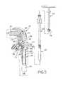
- FIG. 5is a cutaway, exploded view illustrating removal of the hinge post extension
- FIG. 6is a bottom elevational view of the meniscal component of the present invention.
- FIG. 7is a front elevational view thereof
- FIG. 8is a top elevational view of a tibial component in accordance with the present invention.
- FIG. 9is a sectional view of a hinge plug in accordance with the present invention.
- FIG. 10is a side elevational view of a bearing box in accordance with the present invention.
- FIG. 11is a front elevational view thereof
- FIG. 12is a top elevational view thereof
- FIG. 13is a cutaway, exploded view of an alternative embodiment of the knee prosthesis of the present invention.
- FIG. 14is a cutaway view of an assembled knee prosthesis in accordance with the embodiment illustrated in FIG. 13 ;
- FIG. 15is a fragmentary, cutaway view of an alternative embodiment of the hinge post extension and tibial bushing of the present invention.
- FIG. 16is a fragmentary, cutaway view of the embodiment of FIG. 15 illustrating insertion of the hinge post extension into the tibial bushing;
- FIG. 17is a fragmentary, cutaway view of the embodiment of FIG. 15 illustrating the hinge post extension fully inserted into the tibial bushing;
- FIG. 18is an exploded view of an alternative embodiment of the knee prosthesis of the current invention.
- FIG. 19is a sectional view of a meniscal component in accordance with an alternative embodiment of the present invention.
- FIG. 20is an elevational view of a hinge post in accordance with an alternative embodiment of the present invention.
- Knee prosthesis 20in accordance with the present invention is illustrated.
- Knee prosthesis 20generally includes femoral component 22 , tibial component 24 , and meniscal component 26 .
- Hinge post 40is rotatably connected to femoral component 22 and includes elongate hinge post extension aperture 112 ( FIGS. 3-6 , 13 , and 14 ).
- Elongate aperture 112accommodates placement of hinge post extension 42 therein.
- Hinge post extension 42thereafter traverses hinge post aperture 114 in meniscal component 26 and hinge post extension aperture 110 ( FIGS. 3-6 , 13 and 14 ) in tibial component 24 .
- Elongate hinge post extension aperture 112 of hinge post 40advantageously allows for anterior placement of hinge post extension 42 during surgical implantation of knee prosthesis 20 of the present invention.
- hinge post extension 42includes locking taper 46 and cylindrical extension 48 .
- Hinge post extension aperture 112includes a mating locking taper to cooperate with locking taper 46 and lock hinge post extension 42 to hinge post 40 .
- hinge plug 38may be threaded into hinge plug threads 54 in elongate aperture 112 of hinge post 40 ( FIG. 4 ).
- Hinge plug 38abuts the end of hinge post extension 42 and thereby facilitates locking of morse taper 46 in elongate aperture 112 .
- locking taper 46comprises a two degree locking taper.
- Hinge post extension 42is typically formed as a one-piece construction of an inert metal such as, e.g., a cobalt-chromium alloy. Hinge post extension 42 may, however, be constructed of other bio-compatible metals or alloys, such as titanium. Throughout this document reference will be made to various components formed of a cobalt-chromium alloy. Any such component may also be constructed of other bio-compatible metals or alloys such as titanium, as is well-known. As illustrated in FIG. 4 , hinge plug wrench 102 is utilized to thread hinge plug 38 into hinge plug threads 54 of hinge post 40 . As illustrated in FIG. 9 , hinge plug 38 includes locking material 100 to provide a locking connection between hinge plug 38 and hinge plug threads 54 in hinge post 40 . Hinge plug 38 is, in one exemplary embodiment formed of a cobalt-chromium alloy. Locking material 100 comprises any suitable biocompatible polymer such as, e.g., ultra-high molecular weight polyethylene (UHMWPE).
- femoral component 22includes condyler bearing surfaces 28 , 30 with bearing box wall 76 positioned therebetween.
- Femoral component 22further includes external side walls 82 , only one of which can be seen in FIG. 2 .
- Condyler bearing surfaces 28 , 30are smooth and highly polished, generally spheroidally shaped and extend outwardly from external side walls 82 , as is well known in the industry.
- Femoral component 22further includes modular femoral stem 32 for insertion into femur 116 ( FIGS. 3-5 , 13 , and 14 ), as is known in the art.
- Femoral component 22further includes internal side walls 80 , only one of which is illustrated in FIG. 2 .
- Femoral component 22is typically formed as a one-piece construction of an inert metal such as, e.g., a cobalt-chromium alloy.
- Bearing box 70is designed for placement between condyler bearing surfaces 28 , 30 of femoral component 22 as illustrated, e.g., in FIG. 1 .
- Bearing box 70is further illustrated in FIGS. 10-12 and includes affixing protrusions 72 , hinge pin aperture 62 , hyperextension stop 66 , and anti-rotation surface 78 .
- femoral component 22includes affixing protrusion apertures 74 sized to receive affixing protrusions 72 .
- bearing box 70operably positioned on femoral component 22 , with anti-rotation surface 78 flush with bearing box wall 76 of femoral component 22 , and affixing protrusions 72 received in affixing protrusion apertures 74 .
- the abutting relationship of anti-rotation surface 78 with bearing box wall 76discourages rotation of bearing box 70 about the longitudinal axis of affixing protrusions 72 .
- hinge pin apertures 62 of bearing box 70align with threaded hinge pin aperture 56 and hinge pin aperture 58 of femoral component 22 .
- Bearing box 70can be formed of any suitable plastic, such as, e.g., UHMWPE.
- Hinge post 40is rotatably connected to femoral component 22 via hinge pin 34 .
- Hinge post 40is placed between opposing walls of bearing box 70 and is positioned so that hinge pin aperture 52 is aligned with apertures 56 , 58 , and 62 .
- the opposing walls of bearing box 70thus act as a bearing surface between hinge post 40 and internal side walls 80 of femoral component 22 .
- hinge pin sleeve 36Prior to placement of hinge post 40 between opposing walls of bearing box 70 , hinge pin sleeve 36 is operably positioned within hinge pin aperture 52 of hinge post 40 .
- Hinge post 40is formed from a cobalt-chromium alloy, while hinge pin sleeve 36 is formed from a suitable plastic, such as, e.g., UHMWPE.
- Hinge pin sleeve 36acts as a bearing between hinge pin aperture 52 of hinge post 40 and hinge pin 34 . Accordingly, hinge pin sleeve 36 includes hinge pin aperture 50 sized to accommodate hinge pin 34 . After positioning of hinge post 40 between the opposing walls of bearing box 70 , hinge pin 34 is positioned through apertures 56 , 62 , 50 , and 58 . Hinge pin threads 60 are thereafter threadedly engaged in the threads of threaded hinge pin aperture 56 until the head of hinge pin 34 is flush with external side wall 82 .
- hinge pin plug 120is positioned within the hexagonal indentation of hinge pin 34 after installation of hinge pin 34 as described above. When positioned within the hexagonal indentation of hinge pin 34 , hinge pin plug 120 is flush with the head of hinge pin 34 . In use, hinge pin plug 120 substantially prohibits the entry of foreign materials into the hexagonal indentation of hinge pin 34 . For example, hinge pin plug 120 substantially prohibits bone growth into the hexagonal indentation of hinge pin 34 , as well as prohibiting positioning of bone cement therein.
- the above-described connection of hinge post 40 to femoral component 22is performed prior to implantation of femoral component 22 . Femoral component 22 is packaged and sold with bearing box 70 , hinge post 40 , hinge pin sleeve 36 , hinge pin 34 , and hinge pin plug 120 preassembled as described above, with the assembly preferably occurring in the manufacturing environment.
- hinge post 40 to femoral component 22eliminates a number of meticulous assembly steps (many of which were performed during implantation) which were required with constrained knees of the prior art. Furthermore, the assembly of hinge post 40 and femoral component 22 as described above facilitates replacement of various portions of knee prosthesis 20 . Specifically, the threaded connection of hinge pin 34 to femoral component 22 allows for removal and replacement of various components of knee prosthesis including, e.g., bearing box 70 , hinge pin sleeve 36 , and hinge post 40 .
- femoral bone stockmay abut external side walls 82 of femoral component 22 and extend to the underside of condyler bearing surfaces 28 , 30 .
- a hole sawis utilized to remove a relatively small portion of femoral bone stock to provide access to hinge pin 34 .
- femoral component 22does not require extensive removal of femoral bone stock for implantation thereof (since bone stock can extend to the underside of condylar bearing surfaces 28 , 30 ), and, furthermore, does not require removal of femoral component 22 to effect replacement of, e.g., hinge post 40 , bearing box 70 , or hinge pin sleeve 36 .
- hinge pin plug 120Upon accessing hinge pin 34 (e.g., utilizing a hole saw as described above), hinge pin plug 120 is removed, e.g., with a scalpel and forceps to provide access to the hexagonal indentation of hinge pin 34 so that a hexagonal wrench may be inserted therein to unthread hinge pin 34 from femoral component 22 .
- Knee prosthesis 20includes a pair of hyperextension stop mechanisms.
- the first hyperextension stopcomprises a portion of condylar bearing surfaces 28 , 30 of increased radius of curvature as compared to the remaining condylar bearing surface. At three degrees of hyperextension this portion of increased radius of curvature will contact meniscal component 26 and act to retard further hyperextension. If hyperextension continues, the area of increased radius of curvature will cause femoral component 22 to lift away from meniscal component 26 .
- the second hyperextension stop mechanismfunctions at four degrees of hyperextension to prohibit further hyperextension of knee prosthesis 20 .
- the second hyperextension stop mechanismcomprises hyperextension stop surface 66 of hinge post 40 and hyperextension stop 68 of bearing box 70 .
- Hyperextension stop surface 66comprises the concave back wall of cannulated hinge post 40 as illustrated, e.g., in FIGS. 2 and 3 .
- Hyperextension stop 68 of bearing box 70comprises a protrusion extending from the back wall of bearing box 70 opposite anti-rotation surface 78 .
- Hyperextension stop 68includes a convex outer surface as illustrated, e.g., in FIG. 12 .
- Hyperextension stop surface 66 of hinge post 40cooperates with hyperextension stop 68 of bearing box 70 to provide a hyperextension stop for knee prosthesis 20 .
- Concave hyperextension stop surface 66becomes flush with the convex outer surface of hyperextension stop 68 of bearing box 70 at four degrees of hyperextension to prevent further hyperextension of knee prosthesis 20 .
- Tibial component 24is depicted in FIGS. 1-5 , 8 , 13 , and 14 . As illustrated, e.g., in FIG. 2 , tibial component 24 includes tibial tray 98 connected to tibial stem 92 . Stabilizing ribs 94 stabilize tibial tray 98 relative to tibial stem 92 and impede rotation of tibial component 24 in tibia 118 (see, e.g., FIG. 3 ). In one exemplary embodiment, tibial component 24 is formed from a cobalt-chromium alloy. Tibial component 24 further includes tibial bushing 64 positioned within hinge post extension aperture 110 .
- Tibial bushing 64is formed of plastic, such as, e.g., UHMWPE and provides a bearing surface between hinge post extension 42 and hinge post extension aperture 110 of tibial component 24 .
- meniscal component 26comprises a rotating bearing, and, thus, hinge post extension 42 will rotate relative to tibial component 24 .
- Tibial bushing 64facilitates this rotation of hinge post extension 42 .
- Tibial component 24further includes rotation protrusion 96 .
- rotation protrusion 96protrudes upwardly from tibial tray 98 of tibial component 24 and further extends in a plane substantially parallel to tibial tray 98 .
- Rotation protrusion 96cooperates with cutout 90 of meniscal component 26 to guide rotation of meniscal component 26 about hinge post extension 42 , as further described hereinbelow.
- meniscal component 26is illustrated in FIGS. 1-7 , 13 , and 14 .
- Meniscal component 26is formed from a suitable plastic such as, e.g., UHMWPE and provides a rotating bearing surface between femoral component 22 and tibial component 24 .
- Meniscal component 26includes bearing surfaces 86 , 88 which contact condylar bearing surfaces 28 , 30 of femoral component 22 during movement of knee prosthesis 20 .
- meniscal component 26further includes hinge post aperture 114 accommodating passage of hinge post 40 and, consequently, hinge post extension 42 therethrough.
- Meniscal component 26is operable to rotate about the longitudinal axis of hinge post extension 42 to form a rotating bearing.
- Meniscal components of varying heightsmay be constructed in accordance with the present invention.
- meniscal component 26is packaged for sale and use together with hinge post extension 42 to facilitate component choice and, in one embodiment, to ensure proper extension of hinge post extension 42 into tibial component 24 .
- the extension of hinge post extension 42 into tibial component 24functions to prevent separation of knee prosthesis 20 after implantation thereof.
- the femoral component of a knee prosthesismay, in some situations, move relative to and away from the tibial component in a direction parallel to the longitudinal axis of the hinge post extension.
- hinge post extension 42is made to be of sufficient length to be retained within tibial component 24 even in situations in which femoral component 22 moves as described immediately supra. In one exemplary embodiment, hinge post extension 42 extends four centimeters into hinge post extension aperture 110 in tibial component 24 .
- Meniscal component 26includes cutout 90 which cooperates with rotation protrusion 96 of tibial component 24 to guide rotation of meniscal component 26 and to resist lifting of meniscal component 26 from tibial tray 98 of tibial component 24 .
- cutout 90accommodates the portion (i.e., lip) of rotation protrusion 96 extending in a plane substantially parallel to the plane containing tibial tray 98 , with a portion (i.e., lip) of meniscal component 26 being positioned between rotation protrusion 96 and tibial tray 98 in a direction substantially perpendicular to the plane containing tibial tray 98 .
- This configurationfunctions to discourage displacement of meniscal component 26 away from tibial tray 98 in a direction parallel to the longitudinal axis of hinge post extension 42 . Furthermore, rotation protrusion 96 acts against the back of cutout 90 to limit rotation of meniscal component 26 about the longitudinal axis of hinge post extension 42 .
- meniscal component 26may be slid out from between tibial component 24 and femoral component 22 when the hinge post extension 42 has been removed from knee prosthesis 20 .
- hinge post aperture 114is sized to allow rotation of hinge post 40 so that meniscal component 26 may be slid out from its position between femoral component 22 and tibial component 24 .
- FIG. 5illustrates removal of hinge post extension 42 to accommodate replacement of meniscal component 26 .
- hinge plug wrench 102engages hinge plug 38 for removal thereof.
- slap hammer 104is threadedly engaged with threaded aperture 44 in hinge post extension 42 . Slap hammer 104 may then be utilized to unlock the engagement of locking taper 46 in elongate hinge post extension aperture 112 so that hinge post extension 42 may be removed.
- FIGS. 13 and 14illustrate an alternative embodiment of the knee prosthesis of the current invention.
- This alternative embodimentutilizes hinge post extension 42 a having locking taper 46 a, cylindrical extension 48 a, and flange 106 .
- a locking instrumentmay be utilized to apply force atop hinge post extension 42 a so that locking taper 46 a is seated in elongate hinge post extension aperture 112 and locked therein.
- Flange 106may be utilized to facilitate removal of hinge post extension 42 a.
- set screw 108may be utilized as a secondary lock for hinge post extension 42 a.
- the knee prosthesis illustrated in FIGS. 13 and 14is constructed as described above with respect to the first embodiment of the knee prosthesis in accordance with the present invention.
- FIGS. 15 , 16 and 17illustrate an alternative embodiment of the hinge post extension and tibial bushing of the present invention.
- tibial component 24 aincludes annular tibial bushing expansion groove 122 formed in hinge post extension aperture 110 .
- Tibial bushing 64 aincludes retaining flange 130 positioned within annular tibial bushing expansion groove 122 .
- FIG. 15illustrates insertion of cylindrical extension 48 b of the hinge post extension into tibial bushing 64 a positioned within tibial component 24 a.
- annular locking protrusion 128 of tibial bushing 64 aAs cylindrical extension 48 b proceeds into tibial bushing 64 a, bevel 126 contacts annular locking protrusion 128 of tibial bushing 64 a and causes outward movement of retaining flange 130 to allow cylindrical extension 48 b to proceed to its seated position as illustrated in FIG. 17 .
- Annular tibial bushing expansion groove 122is sized to allow radial expansion of retaining flange 130 to accommodate placement of cylindrical extension 48 b within tibial bushing 64 a. In the fully seated position ( FIG. 17 ) cylindrical extension 48 b is locked in place by the engagement of annular locking protrusion 128 in annular locking groove 124 .
- Tibial bushing 64 ais, in one exemplary embodiment, formed of UHMWPE
- FIGS. 18 and 19illustrate another alternative embodiment of the knee prosthesis of the current invention.
- locking clip 134is utilized to retain the position of hinge post 40 b within hinge post aperture 114 of meniscal component 26 a.
- Hinge post 40 bis rotatably attached to femoral component 22 utilizing hinge pin 34 as described above.
- hinge post 40 bincludes locking clip grooves 132
- meniscal component 26 aincludes locking clip apertures 136 .
- locking clip 134is positioned as illustrated in FIG. 19 with each prong of locking clip 134 being inserted into locking clip apertures 136 of meniscal component 26 a. As illustrated in FIG.
- This embodiment of the knee prosthesis of the current inventionmay further utilize a meniscal component cutout together with a rotation protrusion on the tibial component to resist lifting of the meniscal component from the tibial tray as described above.
- FIG. 20illustrates a further alternative embodiment of the hinge post of the present invention.
- Hinge post 40 c illustrated in FIG. 20includes reinforcing material 138 to strengthen hinge post 40 c.
Landscapes
- Health & Medical Sciences (AREA)
- Orthopedic Medicine & Surgery (AREA)
- Physical Education & Sports Medicine (AREA)
- Cardiology (AREA)
- Oral & Maxillofacial Surgery (AREA)
- Transplantation (AREA)
- Engineering & Computer Science (AREA)
- Biomedical Technology (AREA)
- Heart & Thoracic Surgery (AREA)
- Vascular Medicine (AREA)
- Life Sciences & Earth Sciences (AREA)
- Animal Behavior & Ethology (AREA)
- General Health & Medical Sciences (AREA)
- Public Health (AREA)
- Veterinary Medicine (AREA)
- Prostheses (AREA)
Abstract
Description
This is a continuation of application Ser. No. 09/771,061, filed Jan. 29, 2001, now U.S. Pat. No. 6,485,519.
1. Field of the Invention
The present invention relates to prosthetic joints, and, more particularly to a constrained prosthetic knee having a modular hinge post and a rotating bearing.
2. Description of the Related Art
Generally, the knee is formed by the pair of condyles at the distal portion of the femur, the lower surfaces of which bear upon the correspondingly shaped proximal surface plateau of the tibia. The femur and tibia are connected by means of ligaments such as, the posterior cruciate ligament, the lateral collateral ligament, the medial collateral ligament, and the anterior cruciate ligament. These ligaments provide stability to the joint formed by the femur and tibia (i.e., the knee).
In a broad sense, prosthetic knee joints can be considered either constrained or unconstrained. For the purposes of this discussion, constrained prosthetic knees include femoral and tibial prosthetic components which are mechanically linked or constrained to each other by a hinge structure. An unconstrained prosthetic knee includes femoral and tibial components which are not mechanically linked. An unconstrained knee utilizes the patient's existing ligaments to provide joint stability. With this in mind, constrained prosthetic knees have particular applicability to cases in which a patient has experienced ligament loss and/or the existing ligaments do not provide adequate support and stability to the knee.
Tibial components of a prosthetic knee can be formed as a one-piece configuration in which the tibial tray forms the meniscal component of the prosthetic knee. Various other prosthetic knees utilize a modular meniscal component separate from the tibial component. Devices utilizing modular meniscal components include those in which the meniscal component (i.e., tibial bearing surface) is fixed to the tibial tray portion of the tibial component and is incapable of movement relative thereto. Alternative devices utilize a modular meniscal component capable of movement relative to the tibial tray. Devices in which relative rotational movement occurs between the meniscal component and the tibial component are typically referred to as rotating bearing knees. Rotating bearing knees thus allow movement between the bearing (i.e., meniscal component) and the tibial tray, as well as movement between the femoral component and the tibial bearing.
Constrained knees of the prior art include constructions in which a hinge post extension is first positioned within a tibial component (with an end protruding therefrom) and is thereafter connected to the femoral component by positioning the hinge post (rotatably attached to the femoral component) over the top of the protruding end of the hinge post extension and thereafter connecting the hinge post extension to the hinge post, e.g., by threading the hinge post extension into the hinge post. After making this connection, the meniscal component is thereafter slid into position between the femoral component and the tibial component. Meniscal components utilized with these prior art prosthetic knees were fixed to the tibial component.
The present invention is directed to a constrained knee prosthesis with a rotating bearing. The knee prosthesis of the present invention is structured to facilitate implantation thereof. The present invention is further directed to a prosthetic knee implant set having a plurality of matched modular hinge post and meniscal component pairs.
The present invention provides an improved constrained knee prosthesis having a cannulated hinge post facilitating implantation of the knee prosthesis in a relatively minimally invasive procedure. The prosthetic knee implant set of the current invention includes a separately packaged femoral component, a separately packaged tibial component, and a third package containing a hinge post extension and the meniscal component. Packaging the individual components of a knee prosthesis in this fashion insures that the appropriate hinge post extension is readily available. A bearing box is interposed between the hinge post and the femoral component. The bearing box includes a hyperextension stop which cooperates with the hinge post to prevent hyperextension of the knee prosthesis. Various structures are utilized to prevent the disengagement of the constrained knee prosthesis of the present invention.
A prosthetic knee constructed in accordance with the present invention includes a femoral component having a pair of condyler surfaces and a hinge post rotatably connected to the femoral component between the condyler surfaces. The hinge post is cannulated and accommodates insertion of a hinge post extension shaft therein. The hinge post and hinge post extension include cooperating locking tapers for locking the hinge post extension to the hinge post. Additionally, the hinge post includes internal threads so that a set screw may be threaded therein to further hold the hinge post extension in place. The tibial component includes a hinge post extension aperture into which the hinge post is seated. The meniscal component similarly includes an aperture to accommodate the hinge post and hinge post extension. The meniscal component of the current invention is free to rotate about the hinge post during flexion and extension of the knee joint.
Having a cannulated hinge post through which a hinge post extension may be anteriorly positioned and secured advantageously allows for a relatively minimally invasive knee replacement procedure.
The present invention advantageously provides a constrained prosthetic knee having a rotating bearing flush with the condyler surfaces of the femoral component.
Another advantage of the present invention is the packaging of the prosthesis components and specifically the packaging of the appropriate hinge post extension together with a meniscal component.
The above-mentioned and other features and advantages of this invention, and the manner of attaining of them, will become more apparent and the invention itself will be better understood by reference to the following description of an embodiment of the invention taken in conjunction with the accompanying drawings, wherein:
Corresponding reference characters indicate corresponding parts throughout the several views. Although the drawings represent embodiments of the invention, the drawings are not necessarily to scale and certain features may be exaggerated to better illustrate and explain the invention. The exemplifications set out herein illustrate embodiments of the invention, in alternative forms, and such exemplifications are not to be construed as limiting the scope of the invention in any manner.
Referring now to the drawings and particularly toFIG. 2 ,knee prosthesis 20 in accordance with the present invention is illustrated.Knee prosthesis 20 generally includesfemoral component 22,tibial component 24, andmeniscal component 26. Hinge post40 is rotatably connected tofemoral component 22 and includes elongate hinge post extension aperture112 (FIGS. 3-6 ,13, and14).Elongate aperture 112 accommodates placement ofhinge post extension 42 therein.Hinge post extension 42 thereafter traverses hingepost aperture 114 inmeniscal component 26 and hinge post extension aperture110 (FIGS. 3-6 ,13 and14) intibial component 24. Elongate hingepost extension aperture 112 of hinge post40 advantageously allows for anterior placement ofhinge post extension 42 during surgical implantation ofknee prosthesis 20 of the present invention.
As illustrated inFIG. 2 , hingepost extension 42 includes lockingtaper 46 andcylindrical extension 48. Hingepost extension aperture 112 includes a mating locking taper to cooperate with lockingtaper 46 and lock hingepost extension 42 to hingepost 40. After positioning ofhinge post extension 42 throughapertures hinge plug threads 54 inelongate aperture 112 of hinge post40 (FIG. 4 ).Hinge plug 38 abuts the end ofhinge post extension 42 and thereby facilitates locking ofmorse taper 46 inelongate aperture 112. In one exemplary embodiment, lockingtaper 46 comprises a two degree locking taper. Whenprosthetic knee 20 is assembled as illustrated inFIG. 1 , condyler bearing surfaces28,30 abut bearing surfaces86,88 (see, e.g.,FIG. 2 ) inmeniscal component 26.
As illustrated, e.g., inFIG. 2 ,femoral component 22 includes condyler bearing surfaces28,30 with bearingbox wall 76 positioned therebetween.Femoral component 22 further includesexternal side walls 82, only one of which can be seen inFIG. 2 . Condyler bearing surfaces28,30 are smooth and highly polished, generally spheroidally shaped and extend outwardly fromexternal side walls 82, as is well known in the industry.Femoral component 22 further includes modularfemoral stem 32 for insertion into femur116 (FIGS. 3-5 ,13, and14), as is known in the art.Femoral component 22 further includes internal side walls80, only one of which is illustrated inFIG. 2 . Internal side walls80 are substantially perpendicular to bearingbox wall 76 and extend outwardly therefrom.Femoral component 22 is typically formed as a one-piece construction of an inert metal such as, e.g., a cobalt-chromium alloy.
Hinge post40 is rotatably connected tofemoral component 22 viahinge pin 34. Hinge post40 is placed between opposing walls of bearingbox 70 and is positioned so thathinge pin aperture 52 is aligned withapertures box 70 thus act as a bearing surface betweenhinge post 40 and internal side walls80 offemoral component 22. Prior to placement of hinge post40 between opposing walls of bearingbox 70,hinge pin sleeve 36 is operably positioned withinhinge pin aperture 52 ofhinge post 40. Hinge post40 is formed from a cobalt-chromium alloy, whilehinge pin sleeve 36 is formed from a suitable plastic, such as, e.g., UHMWPE.Hinge pin sleeve 36 acts as a bearing betweenhinge pin aperture 52 ofhinge post 40 andhinge pin 34. Accordingly,hinge pin sleeve 36 includeshinge pin aperture 50 sized to accommodatehinge pin 34. After positioning of hinge post40 between the opposing walls of bearingbox 70,hinge pin 34 is positioned throughapertures Hinge pin threads 60 are thereafter threadedly engaged in the threads of threadedhinge pin aperture 56 until the head ofhinge pin 34 is flush withexternal side wall 82.
As illustrated inFIG. 1 ,hinge pin plug 120 is positioned within the hexagonal indentation ofhinge pin 34 after installation ofhinge pin 34 as described above. When positioned within the hexagonal indentation ofhinge pin 34,hinge pin plug 120 is flush with the head ofhinge pin 34. In use,hinge pin plug 120 substantially prohibits the entry of foreign materials into the hexagonal indentation ofhinge pin 34. For example,hinge pin plug 120 substantially prohibits bone growth into the hexagonal indentation ofhinge pin 34, as well as prohibiting positioning of bone cement therein. The above-described connection of hinge post40 tofemoral component 22 is performed prior to implantation offemoral component 22.Femoral component 22 is packaged and sold with bearingbox 70, hingepost 40,hinge pin sleeve 36,hinge pin 34, and hingepin plug 120 preassembled as described above, with the assembly preferably occurring in the manufacturing environment.
Pre-assembly of hinge post40 tofemoral component 22 eliminates a number of meticulous assembly steps (many of which were performed during implantation) which were required with constrained knees of the prior art. Furthermore, the assembly ofhinge post 40 andfemoral component 22 as described above facilitates replacement of various portions ofknee prosthesis 20. Specifically, the threaded connection ofhinge pin 34 tofemoral component 22 allows for removal and replacement of various components of knee prosthesis including, e.g., bearingbox 70,hinge pin sleeve 36, and hingepost 40.
In use, femoral bone stock may abutexternal side walls 82 offemoral component 22 and extend to the underside of condyler bearing surfaces28,30. To removehinge pin 34, a hole saw is utilized to remove a relatively small portion of femoral bone stock to provide access to hingepin 34. Advantageously,femoral component 22 does not require extensive removal of femoral bone stock for implantation thereof (since bone stock can extend to the underside of condylar bearing surfaces28,30), and, furthermore, does not require removal offemoral component 22 to effect replacement of, e.g., hingepost 40, bearingbox 70, or hingepin sleeve 36. Upon accessing hinge pin34 (e.g., utilizing a hole saw as described above),hinge pin plug 120 is removed, e.g., with a scalpel and forceps to provide access to the hexagonal indentation ofhinge pin 34 so that a hexagonal wrench may be inserted therein to unthreadhinge pin 34 fromfemoral component 22.
One embodiment ofmeniscal component 26 is illustrated inFIGS. 1-7 ,13, and14.Meniscal component 26 is formed from a suitable plastic such as, e.g., UHMWPE and provides a rotating bearing surface betweenfemoral component 22 andtibial component 24.Meniscal component 26 includes bearing surfaces86,88 which contact condylar bearing surfaces28,30 offemoral component 22 during movement ofknee prosthesis 20. As described above,meniscal component 26 further includeshinge post aperture 114 accommodating passage ofhinge post 40 and, consequently, hingepost extension 42 therethrough.Meniscal component 26 is operable to rotate about the longitudinal axis ofhinge post extension 42 to form a rotating bearing.
Meniscal components of varying heights may be constructed in accordance with the present invention. In one advantageous aspect of the present invention,meniscal component 26 is packaged for sale and use together withhinge post extension 42 to facilitate component choice and, in one embodiment, to ensure proper extension ofhinge post extension 42 intotibial component 24. The extension ofhinge post extension 42 intotibial component 24 functions to prevent separation ofknee prosthesis 20 after implantation thereof. As is known in the art, the femoral component of a knee prosthesis may, in some situations, move relative to and away from the tibial component in a direction parallel to the longitudinal axis of the hinge post extension. With this in mind, hingepost extension 42 is made to be of sufficient length to be retained withintibial component 24 even in situations in whichfemoral component 22 moves as described immediately supra. In one exemplary embodiment, hingepost extension 42 extends four centimeters into hingepost extension aperture 110 intibial component 24.
As illustrated inFIG. 5 ,meniscal component 26 may be slid out from betweentibial component 24 andfemoral component 22 when thehinge post extension 42 has been removed fromknee prosthesis 20. As illustrated, hingepost aperture 114 is sized to allow rotation of hinge post40 so thatmeniscal component 26 may be slid out from its position betweenfemoral component 22 andtibial component 24. This configuration allows for replacement of an implantedmeniscal component 26 without requiring removal ofhinge post 40.FIG. 5 illustrates removal ofhinge post extension 42 to accommodate replacement ofmeniscal component 26. As illustrated, hingeplug wrench 102 engageshinge plug 38 for removal thereof. After removal ofhinge plug 38,slap hammer 104 is threadedly engaged with threadedaperture 44 inhinge post extension 42.Slap hammer 104 may then be utilized to unlock the engagement of lockingtaper 46 in elongate hingepost extension aperture 112 so thathinge post extension 42 may be removed.
While this invention has been described as having exemplary designs, the present invention may be further modified within the spirit and scope of this disclosure. This application is therefore intended to cover any variations, uses, or adaptations of the invention using its general principles. Further, this application is intended to cover such departures from the present disclosure as come within known or customary practice in the art to which this invention pertains.
Claims (22)
1. A prosthetic femoral component, comprising:
a femoral component body;
a hinge post having a longitudinal axis, said hinge post rotatably connected to said femoral component body, said hinge post rotatable relative to said femoral component body bout an axis of rotation, said hinge post including an elongate aperture, along said longitudinal axis aid elongate aperture transverse to said axis of rotation.
2. The prosthetic femoral component ofclaim 1 , further comprising: A prosthetic knee assembly, comprising:
a femoral component body that includes a first internal side wall opposing a second internal side wall;
a hinge pin having a longitudinal hinge pin axis;
a hinge post positioned between the first internal side wall and the second internal side wall of the femoral component body and having a longitudinal hinge post axis, said hinge pin fixed to said femoral component body and passing through a hinge pin aperture in said hinge post for rotatably, hingedly connecting said hinge post to said femoral component body so that rotation of said hinge post relative to said femoral component body is defined about the longitudinal hinge pin axis, said hinge post including an elongate hinge post extension aperture along said longitudinal hinge post axis, said elongate hinge post extension aperture transverse to said longitudinal hinge pin axis; and
a hinge post extension removeably locked to said hinge post, said elongate hinge post extension aperture of said hinge post sized for placement of said hinge post extension therein, whereby said hinge post extension traverses a first end of said elongate hinge post extension aperture of said hinge post and protrudes from a second end of said elongate hinge post extension aperture of said hinge post.
3. The prosthetic femoral component knee assembly ofclaim 2 , further comprising:
securing means for securing said hinge post extension to said hinge post further comprising a tibial component into which the hinge post extension can be received, wherein, when the femoral component is attached to a femur and the tibial component is attached to a tibia opposite the femur, said hinge post extension can be separated from said hinge post to allow rotation of said hinge post about said longitudinal hinge pin axis without having to rotate the femur or tibia about said longitudinal hinge pin axis.
4. The prosthetic femoral component knee assembly of claim3, wherein said securing means comprises:
a male taper positioned on said hinge post extension; and
a female taper positioned in said elongate aperture, said male taper engageable in said female taper to secure said hinge post extension to said hinge post 2 including cooperating locking tapers removeably locking the hinge post extension to the hinge post.
5. The prosthetic femoral component knee assembly of claim1 2, further comprising:
a bearing box connected to said femoral component body, said bearing box interposed between said hinge post and said femoral component body, said bearing box including a hyperextension stop, said hinge post including a hyperextension stop surface, said hyperextension stop contacting said hyperextension stop surface to prevent further hyperextension of the prosthetic femoral component body beyond a predetermined point of hyperextension.
6. The prosthetic femoral component knee assembly ofclaim 5 , wherein said predetermined point of hyperextension comprises four degrees of hyperextension of the prosthetic knee femoral component body.
7. The prosthetic femoral component knee assembly ofclaim 5 , wherein said hyperextension stop comprises a convex protrusion.
8. The prosthetic femoral component knee assembly ofclaim 5 , wherein said hinge post includes an internal wall, said hyperextension stop surface comprising said internal wall of said hinge post.
9. A prosthetic femoral component, comprising:
a femoral component body;
a hinge post rotatably connected to said femoral component body; and
a bearing box connected to said femoral component body, said bearing box interposed between said hinge post and said femoral component body, said bearing box including a hyperextension stop, said hinge post including a hyperextension stop surface, said hyperextension stop contacting said hyperextension stop surface to prevent further hyperextension of the prosthetic femoral component body beyond a predetermined point of hyperextension.
10. The prosthetic femoral component ofclaim 9 , further comprising: A prosthetic knee assembly, comprising:
a femoral component body;
a hinge post rotatably connected to said femoral component body about a rotational axis;
a bearing box connected to said femoral component body, said bearing box interposed between said hinge post and said femoral component body, said bearing box including a hyperextension stop, said hinge post including a hyperextension stop surface, said hyperextension stop contacting said hyperextension stop surface to prevent further hyperextension of the prosthetic femoral component body beyond a predetermined point of hyperextension; and
a hinge post extension having a longitudinal axis and being removeably locked to said hinge post, an elongate aperture of said hinge post sized for placement of said hinge post extension therein, whereby said hinge post extension traverses a first end of said elongate aperture of said post and protrudes from a second end of said elongate aperture of said hinge post, wherein the longitudinal axis of said hinge post extension is non-intersecting with said rotational axis.
11. The prosthetic femoral component knee assembly ofclaim 10 , further comprising:
securing means for securing said hinge post extension to said hinge post.
12. The prosthetic femoral component knee assembly ofclaim 11 , wherein said securing means comprises:
a male taper positioned on said hinge post extension; and
a female taper positioned in said elongate aperture, said male taper engageable in said female taper to secure said hinge post extension to said hinge post.
13. The prosthetic femoral component knee assembly of claim9 10, wherein said predetermined point of hyperextension comprises four degrees of hyperextension of the prosthetic femoral component body.
14. The prosthetic femoral component knee assembly of claim9 10, wherein said hyperextension stop comprises a convex protrusion.
15. The prosthetic femoral component knee assembly of claim9 10, wherein said hinge post includes an internal wall, said hyperextension stop surface comprising said internal wall of said hinge post.
16. A prosthetic knee, comprising:
a femoral component;
a tibial component;
a meniscal component positioned between said femoral component and said tibial component, said femoral component including a condylar bearing surface, said meniscal component including a cooperative bearing surface facing said condylar bearing surface of said femoral component for contacting said condylar bearing surface, said femoral component rotatably connected to said tibial component;
a hinge pin having a longitudinal hinge pin axis;
a hinge post rotatably connected to said femoral component which includes said hinge pin passing through a hinge pin aperture in said hinge post for rotatably, hingedly connecting said hinge post to said femoral component so that rotation of said hinge post relative to said femoral component is defined about the longitudinal hinge pin axis, said meniscal component including an a hinge post aperture with a longitudinal hinge post aperture axis that is non-intersecting with said longitudinal hinge pin axis, said hinge post positioned within said hinge post aperture; and
a locking clip, said meniscal component including a locking clip aperture, said hinge post including a locking clip groove, said locking clip traversing said locking clip aperture and engaging said locking clip groove to retain said hinge post within said hinge post aperture.
17. A prosthetic knee, comprising:
a femoral component;
a tibial component;
a meniscal component positioned between said femoral component and said tibial component, said femoral component including a condylar bearing surface, said meniscal component including a cooperative bearing surface facing said condylar bearing surface of said femoral component, said femoral component rotatably connected to said tibial component;
a hinge post extension, said hinge post extension rotatably connected to said femoral component, said hinge post extension including an annular groove; and
a tibial bushing including an annular locking protrusion and a retaining flange, said tibial component having a tibial bushing expansion groove, said retaining flange positioned in said tibial bushing expansion groove, said annular locking protrusion engaged in said annular groove.
18. A prosthetic knee, comprising:
a femoral component having a hinge post rotatably connected thereto about a rotational axis;
a tibial component;
a meniscal component positioned between said femoral component and said tibial component, said femoral component including a condylar bearing surface, said meniscal component including a cooperative bearing surface facing said condylar bearing surface of said femoral component for contacting said condylar bearing surface, said meniscal component including an a hinge post aperture having a longitudinal axis that is non-intersecting with said rotational axis, whereby said hinge post is positioned within said hinge post aperture when the prosthetic knee is operably assembled; and
a locking clip, said meniscal component including a locking clip aperture, said hinge post including a locking clip groove, said locking clip traversing said locking clip aperture and engaging said locking clip groove to retain said hinge post within said hinge post aperture.
19. The prosthetic femoral component of claim 2, wherein said first end of said elongate aperture of said hinge post is positioned closer to said hinge pin than said second end of said elongate aperture so that said hinge post extension protrudes from said second end of said elongate aperture of said hinge post in a direction away from said hinge pin.
20. The prosthetic femoral component of claim 10, wherein said first end of said elongate aperture of said hinge post is positioned closer to said femoral component body than said second end of said elongate aperture of said hinge post so that said hinge post extension protrudes from said second end of said elongate aperture of said hinge post in a direction away from said femoral component body.
21. The prosthetic femoral component of claim 2, wherein said hinge pin includes a hexagonal indentation on a first end thereof, said first end being flush with said femoral component, said prosthetic femoral component further comprising a hinge pin plug positioned within said hexagonal indentation and being flush with said first end of said hinge pin.
22. The prosthetic femoral component of claim 2, wherein said longitudinal hinge post axis is non-intersecting with said longitudinal hinge pin axis.
Priority Applications (1)
| Application Number | Priority Date | Filing Date | Title |
|---|---|---|---|
| US12/776,224USRE44476E1 (en) | 2001-01-29 | 2010-05-07 | Constrained prosthetic knee with rotating bearing |
Applications Claiming Priority (3)
| Application Number | Priority Date | Filing Date | Title |
|---|---|---|---|
| US09/771,061US6485519B2 (en) | 2001-01-29 | 2001-01-29 | Constrained prosthetic knee with rotating bearing |
| US10/234,362US6773461B2 (en) | 2001-01-29 | 2002-09-04 | Constrained prosthetic knee with rotating bearing |
| US12/776,224USRE44476E1 (en) | 2001-01-29 | 2010-05-07 | Constrained prosthetic knee with rotating bearing |
Related Parent Applications (1)
| Application Number | Title | Priority Date | Filing Date |
|---|---|---|---|
| US10/234,362ReissueUS6773461B2 (en) | 2001-01-29 | 2002-09-04 | Constrained prosthetic knee with rotating bearing |
Publications (1)
| Publication Number | Publication Date |
|---|---|
| USRE44476E1true USRE44476E1 (en) | 2013-09-03 |
Family
ID=25090569
Family Applications (2)
| Application Number | Title | Priority Date | Filing Date |
|---|---|---|---|
| US09/771,061Expired - LifetimeUS6485519B2 (en) | 2001-01-29 | 2001-01-29 | Constrained prosthetic knee with rotating bearing |
| US12/776,224Expired - LifetimeUSRE44476E1 (en) | 2001-01-29 | 2010-05-07 | Constrained prosthetic knee with rotating bearing |
Family Applications Before (1)
| Application Number | Title | Priority Date | Filing Date |
|---|---|---|---|
| US09/771,061Expired - LifetimeUS6485519B2 (en) | 2001-01-29 | 2001-01-29 | Constrained prosthetic knee with rotating bearing |
Country Status (5)
| Country | Link |
|---|---|
| US (2) | US6485519B2 (en) |
| EP (4) | EP1226800B1 (en) |
| JP (1) | JP4205346B2 (en) |
| AU (1) | AU780963B2 (en) |
| CA (1) | CA2367652C (en) |
Cited By (12)
| Publication number | Priority date | Publication date | Assignee | Title |
|---|---|---|---|---|
| US20120136452A1 (en)* | 2009-07-10 | 2012-05-31 | Medizinische Hochschule Hannover | Knee joint prosthesis and related method |
| US20120330430A1 (en)* | 2001-01-29 | 2012-12-27 | Meyers John E | Constrained prosthetic knee with rotating bearing |
| US20180049880A1 (en)* | 2015-03-05 | 2018-02-22 | Corentec Co., Ltd. | Insert unit for artificial knee joint |
| US20180256346A1 (en)* | 2017-03-10 | 2018-09-13 | Brian D. Byrd | Tibial prosthesis with tibial bearing component securing feature |
| US10835380B2 (en) | 2018-04-30 | 2020-11-17 | Zimmer, Inc. | Posterior stabilized prosthesis system |
| US10898337B2 (en) | 2011-11-18 | 2021-01-26 | Zimmer, Inc. | Tibial bearing component for a knee prosthesis with improved articular characteristics |
| US11160659B2 (en) | 2015-09-21 | 2021-11-02 | Zimmer, Inc. | Prosthesis system including tibial bearing component |
| US11224519B2 (en) | 2010-07-24 | 2022-01-18 | Zimmer, Inc. | Asymmetric tibial components for a knee prosthesis |
| US11324599B2 (en) | 2017-05-12 | 2022-05-10 | Zimmer, Inc. | Femoral prostheses with upsizing and downsizing capabilities |
| US11324598B2 (en) | 2013-08-30 | 2022-05-10 | Zimmer, Inc. | Method for optimizing implant designs |
| US11426282B2 (en) | 2017-11-16 | 2022-08-30 | Zimmer, Inc. | Implants for adding joint inclination to a knee arthroplasty |
| US11471288B2 (en) | 2010-09-10 | 2022-10-18 | Zimmer, Inc. | Motion facilitating tibial components for a knee prosthesis |
Families Citing this family (94)
| Publication number | Priority date | Publication date | Assignee | Title |
|---|---|---|---|---|
| US8603095B2 (en) | 1994-09-02 | 2013-12-10 | Puget Bio Ventures LLC | Apparatuses for femoral and tibial resection |
| US6695848B2 (en) | 1994-09-02 | 2004-02-24 | Hudson Surgical Design, Inc. | Methods for femoral and tibial resection |
| US6972039B2 (en)* | 1999-03-01 | 2005-12-06 | Biomet, Inc. | Floating bearing knee joint prosthesis with a fixed tibial post |
| US6558426B1 (en) | 2000-11-28 | 2003-05-06 | Medidea, Llc | Multiple-cam, posterior-stabilized knee prosthesis |
| US6485519B2 (en) | 2001-01-29 | 2002-11-26 | Bristol-Myers Squibb Company | Constrained prosthetic knee with rotating bearing |
| US6773461B2 (en)* | 2001-01-29 | 2004-08-10 | Zimmer Technology, Inc. | Constrained prosthetic knee with rotating bearing |
| US8062377B2 (en) | 2001-03-05 | 2011-11-22 | Hudson Surgical Design, Inc. | Methods and apparatus for knee arthroplasty |
| US7572292B2 (en) | 2001-12-21 | 2009-08-11 | Smith & Nephew, Inc. | Hinged joint system |
| EP2359775B1 (en)* | 2002-02-20 | 2012-12-26 | Zimmer, Inc. | Knee arthroplasty prosthesis |
| US6875239B2 (en) | 2002-04-25 | 2005-04-05 | Medicinelodge, Inc. | Modular prosthesis for replacing bone and method |
| US20030204268A1 (en)* | 2002-04-25 | 2003-10-30 | Medicinelodge, Inc. | Binary attachment mechanism and method for a modular prosthesis |
| US7105021B2 (en)* | 2002-04-25 | 2006-09-12 | Scimed Life Systems, Inc. | Implantable textile prostheses having PTFE cold drawn yarns |
| US7182786B2 (en) | 2002-04-25 | 2007-02-27 | Zimmer Technology, Inc. | Modular bone implant, tool, and method |
| US6902583B2 (en) | 2002-04-25 | 2005-06-07 | Medicinelodge, Inc. | Tripartite attachment mechanism and method for a modular prosthesis |
| CN100506189C (en) | 2002-08-22 | 2009-07-01 | 维克多姆人体机械公司 | Actuated leg prosthesis for above-knee amputees |
| US7736394B2 (en) | 2002-08-22 | 2010-06-15 | Victhom Human Bionics Inc. | Actuated prosthesis for amputees |
| US6887276B2 (en) | 2002-12-13 | 2005-05-03 | Medicine Lodge, Inc | Modular implant for joint reconstruction and method of use |
| ES2465090T3 (en) | 2002-12-20 | 2014-06-05 | Smith & Nephew, Inc. | High performance knee prostheses |
| US7025789B2 (en)* | 2003-04-29 | 2006-04-11 | The University Of Hong Kong | Prosthetic device and method for total joint replacement in small joint arthroplasty |
| US7198071B2 (en) | 2003-05-02 | 2007-04-03 | Össur Engineering, Inc. | Systems and methods of loading fluid in a prosthetic knee |
| CA2542619C (en) | 2003-10-17 | 2011-10-11 | Smith & Nephew, Inc. | High flexion articular insert |
| US7261740B2 (en)* | 2003-10-29 | 2007-08-28 | Wright Medical Technology, Inc. | Tibial knee prosthesis |
| US7815689B2 (en) | 2003-11-18 | 2010-10-19 | Victhom Human Bionics Inc. | Instrumented prosthetic foot |
| US20050107889A1 (en) | 2003-11-18 | 2005-05-19 | Stephane Bedard | Instrumented prosthetic foot |
| US20060030854A1 (en) | 2004-02-02 | 2006-02-09 | Haines Timothy G | Methods and apparatus for wireplasty bone resection |
| US8021368B2 (en) | 2004-01-14 | 2011-09-20 | Hudson Surgical Design, Inc. | Methods and apparatus for improved cutting tools for resection |
| US9814539B2 (en) | 2004-01-14 | 2017-11-14 | Puget Bioventures Llc | Methods and apparatus for conformable prosthetic implants |
| US8114083B2 (en) | 2004-01-14 | 2012-02-14 | Hudson Surgical Design, Inc. | Methods and apparatus for improved drilling and milling tools for resection |
| US8057550B2 (en) | 2004-02-12 | 2011-11-15 | össur hf. | Transfemoral prosthetic systems and methods for operating the same |
| US7637959B2 (en) | 2004-02-12 | 2009-12-29 | össur hf | Systems and methods for adjusting the angle of a prosthetic ankle based on a measured surface angle |
| US7753960B2 (en)* | 2004-02-26 | 2010-07-13 | Omni Life Science, Inc. | Modular knee prosthesis |
| US20050246028A1 (en)* | 2004-04-28 | 2005-11-03 | Buechel-Pappas Trust | Prosthetic knee |
| WO2005110293A2 (en) | 2004-05-07 | 2005-11-24 | Ossur Engineering, Inc. | Magnetorheologically actuated prosthetic knee |
| US20060014677A1 (en)* | 2004-07-19 | 2006-01-19 | Isotechnika International Inc. | Method for maximizing efficacy and predicting and minimizing toxicity of calcineurin inhibitor compounds |
| CA2863933C (en) | 2004-12-22 | 2018-08-07 | Ossur Hf | Systems and methods for processing limb motion |
| US20060142869A1 (en)* | 2004-12-23 | 2006-06-29 | Gross Thomas P | Knee prosthesis |
| US8801802B2 (en) | 2005-02-16 | 2014-08-12 | össur hf | System and method for data communication with a mechatronic device |
| DE102005015598B4 (en)* | 2005-03-24 | 2015-07-30 | Smith & Nephew Orthopaedics Ag | Knee joint endoprosthesis and prosthesis set with such a knee joint endoprosthesis |
| SE528516C2 (en) | 2005-04-19 | 2006-12-05 | Lisa Gramnaes | Combined active and passive leg prosthesis system and a method for performing a movement cycle with such a system |
| DE102005022584B4 (en)* | 2005-05-09 | 2007-03-08 | Aesculap Ag & Co. Kg | Coupled knee endoprosthesis |
| US8852292B2 (en) | 2005-09-01 | 2014-10-07 | Ossur Hf | System and method for determining terrain transitions |
| US8211181B2 (en)* | 2005-12-14 | 2012-07-03 | New York University | Surface guided knee replacement |
| US7658767B2 (en) | 2006-06-30 | 2010-02-09 | Depuy Products, Inc. | Hinged orthopaedic prosthesis |
| CA2656359C (en) | 2006-06-30 | 2016-11-22 | Smith & Nephew, Inc. | Anatomical motion hinged prosthesis |
| US8114164B2 (en)* | 2006-11-21 | 2012-02-14 | Zafer Termanini | Bicondylar resurfacing prosthesis and method for insertion through direct lateral approach |
| US8974540B2 (en) | 2006-12-07 | 2015-03-10 | Ihip Surgical, Llc | Method and apparatus for attachment in a modular hip replacement or fracture fixation device |
| US8579985B2 (en) | 2006-12-07 | 2013-11-12 | Ihip Surgical, Llc | Method and apparatus for hip replacement |
| EP2094197B8 (en) | 2006-12-07 | 2016-03-09 | IHip Surgical, LLC | Apparatus for total hip replacement |
| US8562616B2 (en) | 2007-10-10 | 2013-10-22 | Biomet Manufacturing, Llc | Knee joint prosthesis system and method for implantation |
| US8187280B2 (en) | 2007-10-10 | 2012-05-29 | Biomet Manufacturing Corp. | Knee joint prosthesis system and method for implantation |
| US8163028B2 (en) | 2007-01-10 | 2012-04-24 | Biomet Manufacturing Corp. | Knee joint prosthesis system and method for implantation |
| US8328873B2 (en) | 2007-01-10 | 2012-12-11 | Biomet Manufacturing Corp. | Knee joint prosthesis system and method for implantation |
| JP5448842B2 (en)* | 2007-01-10 | 2014-03-19 | バイオメト マニファクチャリング コーポレイション | Knee joint prosthesis system and implantation method |
| US8128703B2 (en) | 2007-09-28 | 2012-03-06 | Depuy Products, Inc. | Fixed-bearing knee prosthesis having interchangeable components |
| US8632600B2 (en) | 2007-09-25 | 2014-01-21 | Depuy (Ireland) | Prosthesis with modular extensions |
| US9204967B2 (en) | 2007-09-28 | 2015-12-08 | Depuy (Ireland) | Fixed-bearing knee prosthesis having interchangeable components |
| US7918893B2 (en)* | 2007-09-30 | 2011-04-05 | Depuy Products, Inc. | Hinged orthopaedic prosthesis |
| US7871442B2 (en)* | 2007-11-30 | 2011-01-18 | Howmedica Osteonics Corp. | Knee prosthesis with four degrees freedom |
| US9119723B2 (en) | 2008-06-30 | 2015-09-01 | Depuy (Ireland) | Posterior stabilized orthopaedic prosthesis assembly |
| US8236061B2 (en) | 2008-06-30 | 2012-08-07 | Depuy Products, Inc. | Orthopaedic knee prosthesis having controlled condylar curvature |
| US9168145B2 (en) | 2008-06-30 | 2015-10-27 | Depuy (Ireland) | Posterior stabilized orthopaedic knee prosthesis having controlled condylar curvature |
| US8206451B2 (en) | 2008-06-30 | 2012-06-26 | Depuy Products, Inc. | Posterior stabilized orthopaedic prosthesis |
| US8187335B2 (en) | 2008-06-30 | 2012-05-29 | Depuy Products, Inc. | Posterior stabilized orthopaedic knee prosthesis having controlled condylar curvature |
| US8192498B2 (en) | 2008-06-30 | 2012-06-05 | Depuy Products, Inc. | Posterior cructiate-retaining orthopaedic knee prosthesis having controlled condylar curvature |
| US8828086B2 (en) | 2008-06-30 | 2014-09-09 | Depuy (Ireland) | Orthopaedic femoral component having controlled condylar curvature |
| US9011547B2 (en) | 2010-01-21 | 2015-04-21 | Depuy (Ireland) | Knee prosthesis system |
| US8308808B2 (en) | 2010-02-19 | 2012-11-13 | Biomet Manufacturing Corp. | Latent mobile bearing for prosthetic device |
| US8545571B2 (en) | 2010-07-30 | 2013-10-01 | Howmedica Osteonics Corp. | Stabilized knee prosthesis |
| CA2808090C (en) | 2010-08-12 | 2018-09-11 | Smith & Nephew, Inc. | Structures for use in orthopaedic implant fixation and methods of installation onto a bone |
| US8287601B2 (en) | 2010-09-30 | 2012-10-16 | Depuy Products, Inc. | Femoral component of a knee prosthesis having an angled cement pocket |
| US8317870B2 (en) | 2010-09-30 | 2012-11-27 | Depuy Products, Inc. | Tibial component of a knee prosthesis having an angled cement pocket |
| CN103327937B (en) | 2011-01-27 | 2017-08-08 | 史密夫和内修有限公司 | constrained knee prosthesis |
| WO2012145043A2 (en)* | 2011-04-21 | 2012-10-26 | Signal Medical Corporation | Implant with multi-directional pivoting |
| EP2706928B1 (en) | 2011-05-13 | 2015-08-12 | Biomet Manufacturing, LLC | Bi-cruciate knee system |
| US11771442B2 (en) | 2011-05-13 | 2023-10-03 | Biomet Manufacturing Llc | Bi-cruciate knee system |
| US8617250B2 (en) | 2011-06-17 | 2013-12-31 | Biomet Manufacturing, Llc | Revision knee tibial locking mechanism |
| US8961612B2 (en) | 2012-08-30 | 2015-02-24 | Biomet Manufacturing, Llc | Knee component having orbital interface boss |
| US9561118B2 (en) | 2013-02-26 | 2017-02-07 | össur hf | Prosthetic foot with enhanced stability and elastic energy return |
| GB2512609A (en)* | 2013-04-03 | 2014-10-08 | Fitzbionics Ltd | Total knee replacement prosthesis assembly |
| US9194403B2 (en) | 2014-02-23 | 2015-11-24 | Dylan Pierre Neyme | Modular hinged joint for use with agonist-antagonist tensile inputs |
| DE102014106012B9 (en) | 2014-04-29 | 2015-09-17 | Aesculap Ag | Knee endoprosthesis |
| JP5663692B1 (en)* | 2014-07-17 | 2015-02-04 | 経憲 武井 | Knee joint, and prosthetic leg and power assist device using the same |
| JP2017528219A (en)* | 2014-09-23 | 2017-09-28 | テクレス・ソシエタ・ペル・アチオニTecres S.P.A. | Restraint type spacer device for knee joint |
| DE102015119105A1 (en) | 2015-11-06 | 2017-05-11 | Aesculap Ag | Knee endoprosthesis |
| US10925743B2 (en)* | 2017-09-26 | 2021-02-23 | Stephen J. Incavo | Knee arthroplasty with modular femoral adapters |
| WO2019210323A1 (en)* | 2018-04-27 | 2019-10-31 | Delta Ortho, Llc | Hinge joint system with distal femoral replacement prosthetic knee |
| US10736748B2 (en) | 2018-05-02 | 2020-08-11 | Depuy Ireland Unlimited Company | Orthopaedic prosthetic system for a hinged-knee prosthesis |
| US11116641B2 (en) | 2019-02-05 | 2021-09-14 | Depuy Ireland Unlimited Company | Orthopaedic prosthetic system for a rotating hinged-knee prosthesis |
| US11033396B2 (en) | 2019-02-05 | 2021-06-15 | Depuy Ireland Unlimited Company | Orthopaedic prosthetic system for a rotating hinged-knee prosthesis |
| US11723775B2 (en)* | 2020-08-12 | 2023-08-15 | Asheesh BEDI | Magnetic medical implants |
| TR202101656A2 (en)* | 2021-02-03 | 2022-08-22 | Hipokrat Tibbi Malzemeler Imalat Ve Pazarlama Anonim Sirketi | INNOVATION IN THE WORKING PRINCIPLE OF ROTATIONAL HINGED KNEE PROSTHESES |
| US20230024863A1 (en)* | 2021-07-23 | 2023-01-26 | Microport Orthopedics Holdings Inc. | Endoprosthetic rotating hinge knee assemblies, subassemblies, and methods |
| US20240207061A1 (en)* | 2022-12-22 | 2024-06-27 | Zimmer, Inc. | Tibial component for a constrained prosthetic knee |
| US20240207056A1 (en)* | 2022-12-22 | 2024-06-27 | Zimmer, Inc. | Constrained prosthetic knee |
Citations (230)
| Publication number | Priority date | Publication date | Assignee | Title |
|---|---|---|---|---|
| US1504903A (en) | 1924-05-05 | 1924-08-12 | James F Rowley | Artificial foot |
| US2183076A (en) | 1938-09-16 | 1939-12-12 | Joseph Spievak | Artificial ankle joint |
| US3696446A (en) | 1970-01-30 | 1972-10-10 | Ass De L Ecole Catholique D Ar | Total knee prosthesis |
| DE2122390A1 (en) | 1971-05-06 | 1973-01-04 | Aesculap Werke Ag | KNEE JOINT ENDOPROTHESIS |
| US3708805A (en) | 1969-12-24 | 1973-01-09 | Nat Res Dev | Prosthetic elbow joint |
| DE2154338A1 (en) | 1971-11-02 | 1973-05-17 | Eduard Hartmann | JOINT PROSTHESIS |
| GB1328497A (en) | 1969-09-16 | 1973-08-30 | Nat Res Dev | Artificial knee joint |
| US3813700A (en) | 1973-04-16 | 1974-06-04 | S Tennant | Prosthetic knee device |
| US3816853A (en) | 1971-11-18 | 1974-06-18 | R Elson | Implantable prosthetic knee joint |
| US3824630A (en) | 1972-06-23 | 1974-07-23 | Zimmer Mfg Co | Prosthetic joint for total knee replacement |
| US3837009A (en) | 1972-12-07 | 1974-09-24 | New York Soc Relief Of Rupture | Knee prosthesis |
| US3869729A (en) | 1972-01-05 | 1975-03-11 | Nat Res Dev | Bone joint prosthesis |
| US3909854A (en) | 1973-05-03 | 1975-10-07 | Ysidore M Martinez | Knee implant prosthesis |
| GB1409150A (en) | 1972-09-01 | 1975-10-08 | Sulzer Ag | Prosthetic implant for a knee joint |
| US3918101A (en) | 1973-10-02 | 1975-11-11 | Jean Lagrange | Total knee-joint prosthesis |
| US3924277A (en) | 1971-05-04 | 1975-12-09 | Nat Res Dev | Knee joint prosthesis |
| US3934272A (en) | 1974-11-19 | 1976-01-27 | The University Of Melbourne | Knee prosthesis |
| GB1457147A (en) | 1974-11-19 | 1976-12-01 | Univ Melbourne | Prosthetic knee joint |
| US3996624A (en) | 1975-02-28 | 1976-12-14 | United States Surgical Corporation | Prosthetic knee joint |
| US4016606A (en) | 1975-07-14 | 1977-04-12 | Research Corporation | Knee joint prosthesis |
| GB1475688A (en) | 1974-04-03 | 1977-06-01 | Silentbloc | Flexible joints |
| US4064568A (en) | 1975-11-06 | 1977-12-27 | Sanitatshaus Schuutt & Grundei | Knee-joint endoprostheses |
| GB1507309A (en) | 1974-10-14 | 1978-04-12 | Atomic Energy Authority Uk | Prosthetic knee joints |
| US4092740A (en) | 1975-10-03 | 1978-06-06 | Salomao Eshriqui | Articulated joint prosthesis |
| US4094017A (en) | 1977-02-16 | 1978-06-13 | Larry Stanford Matthews | Knee joint prosthesis with patellar-femoral contact |
| GB1514479A (en) | 1974-10-01 | 1978-06-14 | Elson R | Prosthetic joints |
| US4112522A (en) | 1975-11-04 | 1978-09-12 | Aram Dadurian | Knee-joint prosthesis |
| DE2810748A1 (en) | 1977-05-09 | 1978-11-23 | Hauni Werke Koerber & Co Kg | Artificial knee joint with shafts for fitting into thigh and leg bones - has hinge link with pref. polyethylene guide box and pressure ring |
| US4134158A (en) | 1977-08-22 | 1979-01-16 | Laure Prosthetics, Inc. | Knee joint prosthesis |
| US4136405A (en) | 1977-04-29 | 1979-01-30 | Zimmer U.S.A. | Rotational offset knee prosthesis |
| DE2906458A1 (en) | 1978-02-22 | 1979-08-23 | Howmedica | JOINT PROSTHESIS |
| CA1073151A (en) | 1977-01-10 | 1980-03-11 | Bristol-Myers Squibb Company | Prosthetic joint for total knee replacement |
| FR2445137A1 (en) | 1978-12-29 | 1980-07-25 | Deaux Ets | Knee prosthesis permitting rotary and bending motion - has hinge joint between tibial and femoral components with cammed, profiled surfaces cooperating with tibial stem |
| US4215439A (en) | 1978-10-16 | 1980-08-05 | Zimmer, USA | Semi-restraining knee prosthesis |
| US4216549A (en) | 1977-06-02 | 1980-08-12 | Purdue Research Foundation | Semi-stable total knee prosthesis |
| US4219893A (en) | 1977-09-01 | 1980-09-02 | United States Surgical Corporation | Prosthetic knee joint |
| US4224697A (en) | 1978-09-08 | 1980-09-30 | Hexcel Corporation | Constrained prosthetic knee |
| DE3013155A1 (en) | 1979-04-05 | 1980-10-23 | Minnesota Mining & Mfg | TIBIA PROSTHESIS |
| WO1981000606A1 (en) | 1979-08-31 | 1981-03-05 | Caterpillar Tractor Co | Mount to absorb shocks |
| US4257129A (en) | 1979-05-21 | 1981-03-24 | Volz Robert G | Prosthetic knee joint tibial implant |
| US4262368A (en) | 1979-09-24 | 1981-04-21 | Wright Manufacturing Company | Rotating and hinged knee prosthesis |
| DE3039992A1 (en) | 1979-10-26 | 1981-05-14 | National Research Development Corp., London | ENDOPROTHETIC BONE JOINT DEVICE, IN PARTICULAR FOR THE KNEE JOINT |
| US4268920A (en) | 1977-10-05 | 1981-05-26 | GMT Gesellschaft fur med. Technik mbH | Endoprosthesis for a knee joint |
| GB2070939A (en) | 1980-03-11 | 1981-09-16 | Howmedica | Prosthetic joint |
| US4301553A (en) | 1975-08-15 | 1981-11-24 | United States Surgical Corporation | Prosthetic knee joint |
| EP0046926A2 (en) | 1980-09-03 | 1982-03-10 | Waldemar Link (GmbH & Co.) | Knee joint endoprosthesis |
| US4340978A (en) | 1979-07-02 | 1982-07-27 | Biomedical Engineering Corp. | New Jersey meniscal bearing knee replacement |
| US4358859A (en) | 1979-10-04 | 1982-11-16 | Schurman David J | Articulated prosthetic knee and method for implanting same |
| EP0069683A1 (en) | 1981-07-06 | 1983-01-12 | André Rambert | Full knee-joint prosthesis |
| US4383337A (en) | 1980-10-22 | 1983-05-17 | Zimmer Usa, Inc. | Elbow prosthesis |
| EP0083155A1 (en) | 1981-12-07 | 1983-07-06 | Dow Corning Corporation | Shock absorbing stop for prosthetic devices |
| US4404691A (en) | 1980-03-11 | 1983-09-20 | Howmedica International Inc. | Modular prosthesis assembly |
| GB2120943A (en) | 1982-03-13 | 1983-12-14 | Thackray C F Ltd | Knee prosthesis |
| DE3339102A1 (en) | 1982-11-04 | 1984-05-10 | Howmedica International Inc., Shannon, Clare | Joint prosthesis |
| EP0126978A1 (en) | 1983-04-28 | 1984-12-05 | Feldmühle Aktiengesellschaft | Knee endoprosthesis |
| US4538305A (en) | 1981-05-19 | 1985-09-03 | Gmt Gesellschaft Fur Medizinische Technik Mbh | Articulated prosthesis |
| US4578081A (en) | 1982-02-17 | 1986-03-25 | Howmedica International, Inc. | Bone prosthesis |
| EP0177755A1 (en) | 1984-09-07 | 1986-04-16 | S + G Implants Gmbh | Tibial-prosthetic part of a knee joint endoprosthesis |
| EP0178445A1 (en) | 1984-09-11 | 1986-04-23 | S + G Implants Gmbh | Knee joint endoprosthesis |
| EP0194326A1 (en) | 1983-09-23 | 1986-09-17 | orthoplant Endoprothetik GmbH | Knee-joint endoprosthesis |
| EP0198163A2 (en) | 1985-04-15 | 1986-10-22 | GebràDer Sulzer Aktiengesellschaft | Connection of two parts of an implant |
| DE3529894A1 (en) | 1985-08-21 | 1987-03-05 | Orthoplant Endoprothetik | Knee-joint endoprosthesis |
| EP0214773A2 (en) | 1985-08-12 | 1987-03-18 | Harrington Arthritis Research Center | Joint Prosthesis |
| FR2601873A1 (en) | 1986-07-25 | 1988-01-29 | Cuilleron J | Intracondylar total knee prosthesis |
| EP0265325A1 (en) | 1986-10-14 | 1988-04-27 | S.N.R. Roulements | Knee articulation prosthesis |
| FR2612767A1 (en) | 1987-03-23 | 1988-09-30 | Letournel Emile | Total knee prosthesis |
| US4790853A (en) | 1984-08-29 | 1988-12-13 | Gmt Gesellschaft Fur Medizinische Technik Mbh | Knee joint prosthesis |
| US4790854A (en) | 1982-02-17 | 1988-12-13 | Howmedica International Inc. | Bone prosthesis assembly |
| US4822366A (en) | 1986-10-16 | 1989-04-18 | Boehringer Mannheim Corporation | Modular knee prosthesis |
| US4828564A (en) | 1983-03-22 | 1989-05-09 | National Research Development Corporation | Endoprosthetic bone joint devices |
| US4834758A (en) | 1988-05-26 | 1989-05-30 | New York Society For The Relief Of The Ruptured And Crippled, Maintaining The Hospital For Special Surgery | Bone prosthesis for the leg and thigh |
| WO1989006947A1 (en) | 1988-02-02 | 1989-08-10 | Joint Medical Products Corporation | Prosthetic joint |
| US4865606A (en) | 1987-08-13 | 1989-09-12 | Friedrichsfeld Gmbh Keramik Und Kunststoffwerke | Endoprosthesis for a knee-joint |
| FR2628316A1 (en) | 1988-03-08 | 1989-09-15 | Lebeguec Pierre | Whole knee prosthesis - has one piece implanted at end of femur, other at end of tibia articulating around cross member of T=piece |
| US4923472A (en) | 1988-01-22 | 1990-05-08 | Salus S.R.L. | Artificial knee-joint |
| US4936853A (en) | 1989-01-11 | 1990-06-26 | Kirschner Medical Corporation | Modular knee prosthesis |
| US4938769A (en) | 1989-05-31 | 1990-07-03 | Shaw James A | Modular tibial prosthesis |
| FR2641966A1 (en) | 1989-01-23 | 1990-07-27 | Implants Instr Ch Fab | Device adaptable to total intracondylar prostheses of the knee |
| US4944757A (en) | 1988-11-07 | 1990-07-31 | Martinez David M | Modulator knee prosthesis system |
| US4950298A (en) | 1988-04-08 | 1990-08-21 | Gustilo Ramon B | Modular knee joint prosthesis |
| EP0410237A1 (en) | 1989-07-26 | 1991-01-30 | Bristol-Myers Squibb Company | Knee joint endoprosthesis |
| EP0420460A1 (en) | 1989-09-27 | 1991-04-03 | University College London | Knee prosthesis |
| US5007933A (en) | 1989-01-31 | 1991-04-16 | Osteonics Corp. | Modular knee prosthesis system |
| US5011496A (en) | 1988-02-02 | 1991-04-30 | Joint Medical Products Corporation | Prosthetic joint |
| US5015255A (en) | 1989-05-10 | 1991-05-14 | Spine-Tech, Inc. | Spinal stabilization method |
| US5019103A (en) | 1990-02-05 | 1991-05-28 | Boehringer Mannheim Corporation | Tibial wedge system |
| US5037439A (en) | 1988-04-11 | 1991-08-06 | Albrektsson Bjoern | Knee-joint prosthesis |
| US5061271A (en) | 1989-02-27 | 1991-10-29 | Boehringer Mannheim Corporation | Tool for separating components of a modular joint prosthesis |
| EP0472475A2 (en) | 1990-07-11 | 1992-02-26 | Gilles Bousquet | Bicondylar knee prosthesis |
| US5116375A (en) | 1990-08-27 | 1992-05-26 | Hofmann Aaron A | Knee prosthesis |
| US5123928A (en) | 1989-07-07 | 1992-06-23 | Eska Medical Luebeck Medizintechnik Gmbh | Knee joint endoprosthesis |
| DE4110048C1 (en) | 1991-03-27 | 1992-07-30 | S + G Implants Gmbh, 2400 Luebeck, De | Knee joint prosthesis with femur and tibia portions - has femur condylar shells recessed on ventral side towards shell inside |
| DE4102509A1 (en) | 1991-01-29 | 1992-07-30 | Peter Brehm | Knee-joint prosthesis - where femur part has bearing housing with two-part plastic bearing insert in which connecting rod can pivot but not rotate |
| US5139521A (en) | 1990-01-27 | 1992-08-18 | Ingrid Schelhas | Knee prosthesis |
| US5171283A (en) | 1989-07-11 | 1992-12-15 | Biomedical Engineering Trust | Compound shape rotating bearing |
| US5180383A (en) | 1991-10-09 | 1993-01-19 | Haydon Frank A | Method and device for attaching artificial joint implants to the ends of bones |
| US5194066A (en) | 1988-01-11 | 1993-03-16 | Boehringer Mannheim Corporation | Modular joint prosthesis |
| US5246459A (en) | 1992-02-24 | 1993-09-21 | Elias Sarmed G | Modular tibial support pegs for the tibial component of a prosthetic knee replacement system |
| FR2692475A1 (en) | 1992-06-19 | 1993-12-24 | Montpellier Chirurgie | Total knee replacement. |
| US5282867A (en) | 1992-05-29 | 1994-02-01 | Mikhail Michael W E | Prosthetic knee joint |
| US5290313A (en) | 1992-11-23 | 1994-03-01 | Zimmer, Inc. | Offset prosthetic stem extension |
| FR2696926A1 (en) | 1992-10-19 | 1994-04-22 | Cuilleron J | Total knee prosthesis - has axis with bearing rollers set transversely in upper end of vertical pivot, held in place by rings |
| US5314481A (en) | 1992-11-12 | 1994-05-24 | Wright Medical Technology, Inc. | Hinged knee prosthesis with extended patellar track |
| US5326368A (en) | 1992-09-22 | 1994-07-05 | Howmedica, Inc. | Modular acetabular cup |
| US5330534A (en) | 1992-02-10 | 1994-07-19 | Biomet, Inc. | Knee joint prosthesis with interchangeable components |
| FR2702651A1 (en) | 1993-03-16 | 1994-09-23 | Erato | Knee prosthesis |
| WO1994021198A1 (en) | 1993-03-15 | 1994-09-29 | University College London | Total knee replacement prosthesis |
| US5358527A (en) | 1991-03-22 | 1994-10-25 | Forte Mark R | Total knee prosthesis with resurfacing and posterior stabilization capability |
| US5370700A (en) | 1993-02-19 | 1994-12-06 | Sarkisian; James S. | Prosthetic knee joint |
| US5370701A (en) | 1990-09-28 | 1994-12-06 | Arch Development Corporation | Rotating/sliding contrained prosthetic knee |
| DE9414970U1 (en) | 1994-09-15 | 1994-12-22 | Diehl, Klaus, Prof. Dr., 66123 Saarbrücken | Partially coupled knee prosthesis |
| US5387240A (en) | 1990-11-14 | 1995-02-07 | Arch Development Corporation | Floating bearing prosthetic knee |
| US5395401A (en) | 1991-06-17 | 1995-03-07 | Bahler; Andre | Prosthetic device for a complex joint |
| US5405398A (en) | 1993-08-30 | 1995-04-11 | Intermedics Orthopedics, Inc. | Prosthetic knee with posterior stabilized femoral component |
| US5411555A (en) | 1991-06-11 | 1995-05-02 | Gmt Gesellschaft Fur Medizinische Technik Gmbh | Knee joint prosthesis kit |
| FR2711750A1 (en) | 1993-10-28 | 1995-05-05 | Fii | Device for immobilising a body in a bore |
| US5413607A (en) | 1990-11-29 | 1995-05-09 | Gmt Gesellschaft Fur Medizinische Technik Mbh | Knee joint prosthesis |
| US5427586A (en) | 1992-05-07 | 1995-06-27 | Ingrid Schelhas | Knee-joint endoprosthesis |
| US5458644A (en) | 1991-12-18 | 1995-10-17 | Eska Medical Gmbh & Co. | Knee joint endoprosthesis |
| US5489307A (en) | 1993-02-10 | 1996-02-06 | Spine-Tech, Inc. | Spinal stabilization surgical method |
| US5489311A (en) | 1994-01-21 | 1996-02-06 | Joint Medical Products Corporation | Prosthesis with orientable bearing surface |
| DE4434806A1 (en) | 1994-09-29 | 1996-04-04 | Peter Brehm | Prosthesis for knee joints |
| EP0716839A1 (en) | 1994-12-12 | 1996-06-19 | Biomedical Engineering Trust I | Hinged knee prothesis with condylar bearing |
| JPH08173464A (en) | 1994-12-26 | 1996-07-09 | Kyocera Corp | Artificial knee joint |
| DE69206397T2 (en) | 1991-12-31 | 1996-08-01 | Cuilleron J | Total intracondylar knee prosthesis. |
| EP0724868A1 (en) | 1995-01-31 | 1996-08-07 | SULZER Medizinaltechnik AG | Joint prothesis, in particular a knee prosthesis |
| US5549687A (en) | 1992-12-10 | 1996-08-27 | Wright Medical Technology, Inc. | Retrofit posterior stabilizing housing implant for replacement knee prosthesis |
| US5549689A (en) | 1994-11-28 | 1996-08-27 | Epstein; Norman | Prosthetic knee |
| US5609639A (en) | 1991-02-04 | 1997-03-11 | Walker; Peter S. | Prosthesis for knee replacement |
| US5609643A (en) | 1995-03-13 | 1997-03-11 | Johnson & Johnson Professional, Inc. | Knee joint prosthesis |
| RU2080840C1 (en) | 1993-07-08 | 1997-06-10 | Онкологический научный центр РАМН | Knee joint endoprosthesis and device for fixing it in tibia and femur |
| US5658342A (en) | 1992-11-16 | 1997-08-19 | Arch Development | Stabilized prosthetic knee |
| US5683468A (en) | 1995-03-13 | 1997-11-04 | Pappas; Michael J. | Mobile bearing total joint replacement |
| DE69305434T2 (en) | 1992-06-23 | 1997-11-06 | Medinov Amp S A | Total sliding prosthesis for the knee |
| EP0812582A2 (en) | 1996-06-13 | 1997-12-17 | Industrias Quirurgicas De Levante, S.A. | Knee substitution prosthesis |
| US5702458A (en) | 1994-12-09 | 1997-12-30 | New York Society For The Ruptured And Crippled Maintaining The Hospital For Special Surgery | Joint prosthesis |
| US5702466A (en) | 1992-04-23 | 1997-12-30 | Biomedical Engineering Trust I | Rotational and translational bearing combination in biological joint replacement |
| JPH1014935A (en) | 1996-07-02 | 1998-01-20 | Homuzu Giken:Kk | Cover member for member buried in vivo and member to be buried in vivo |
| FR2751204A1 (en) | 1996-07-16 | 1998-01-23 | Landanger Camus Sa | Knee prosthesis |
| US5725580A (en) | 1994-12-16 | 1998-03-10 | Exactech, Inc. | Hole caps for prosthetic implants |
| US5755804A (en) | 1996-02-21 | 1998-05-26 | Plus Endoprothetik Ag | Endoprosthetic knee joint |
| US5766257A (en) | 1997-01-28 | 1998-06-16 | Implant Manufacturing And Testing Corporation | Artificial joint having natural load transfer |
| US5772661A (en) | 1988-06-13 | 1998-06-30 | Michelson; Gary Karlin | Methods and instrumentation for the surgical correction of human thoracic and lumbar spinal disease from the antero-lateral aspect of the spine |
| US5776200A (en) | 1995-02-15 | 1998-07-07 | Smith & Nephew, Inc. | Tibial trial prosthesis and bone preparation system |
| US5776201A (en) | 1995-10-02 | 1998-07-07 | Johnson & Johnson Professional, Inc. | Modular femoral trial system |
| FR2760352A1 (en) | 1997-03-10 | 1998-09-11 | Philippe Berret | Total knee joint prosthesis |
| US5824102A (en) | 1992-06-19 | 1998-10-20 | Buscayret; Christian | Total knee prosthesis |
| US5879392A (en) | 1996-05-08 | 1999-03-09 | Mcminn; Derek James Wallace | Knee prosthesis |
| US5879394A (en) | 1996-05-28 | 1999-03-09 | Howmedica International Inc. | Tibial element for a replacement knee prosthesis |
| EP0653194B1 (en)* | 1992-10-20 | 1999-03-17 | Fabrique D'implants Et D'instruments Chirurgicaux Societe A Responsabilite Limitee | Total knee prosthesis |
| US5906643A (en) | 1994-07-28 | 1999-05-25 | Walker; Peter Stanley | Stabilised mobile bearing knee |
| FR2771283A1 (en) | 1997-11-24 | 1999-05-28 | Implants & Instr Chirurg | Tibial implant for knee prosthesis |
| EP0923916A1 (en) | 1997-12-19 | 1999-06-23 | Sulzer Orthopädie AG | Knee joint prosthesis |
| DE19809041A1 (en) | 1998-03-04 | 1999-09-09 | Engelbrecht | Knee joint prosthesis of support plus tibia and femur parts |
| US5954770A (en) | 1996-02-21 | 1999-09-21 | Plus Endoprothetik Ag | Endoprosthetic knee joint |
| DE19915053A1 (en) | 1998-04-02 | 1999-10-07 | Beguec Pierre Le | Total knee prosthesis with femur and tibia joint |
| US5964808A (en) | 1996-07-11 | 1999-10-12 | Wright Medical Technology, Inc. | Knee prosthesis |
| FR2777453A1 (en) | 1998-04-20 | 1999-10-22 | Andre Raoult | Complete knee prosthesis |
| US6004352A (en) | 1997-01-10 | 1999-12-21 | Sulzer Orthopaedie Ag | Tibia platform for an artificial knee joint |
| US6080195A (en) | 1998-07-08 | 2000-06-27 | Johnson & Johnson Professional, Inc. | Rotatable and translatable joint prosthesis with posterior stabilization |
| FR2787992A1 (en) | 1999-01-04 | 2000-07-07 | Aesculap Sa | TIBIAL KNEE PROSTHESIS WITH DOUBLE INSERTED BALL JOINT |
| US6099570A (en) | 1997-10-28 | 2000-08-08 | Sulzer Orthopaedie Ag | Knee joint prothesis |
| US6099571A (en) | 1997-07-16 | 2000-08-08 | Knapp; John G. | Joint prosthesis |
| US6117175A (en) | 1994-08-22 | 2000-09-12 | Bosredon; Jean | Spherical knee joint prosthesis |
| US6126692A (en) | 1998-06-25 | 2000-10-03 | New York Society For The Relief Of The Ruptured And Crippled Maintaining The Hospital For Special Surgery | Retaining mechanism for a modular tibial component of a knee prosthesis |
| US6143034A (en) | 1998-07-30 | 2000-11-07 | Sulzer Orthopedics Inc. | Implantable hinged knee prosthesis having tibial baseplate |
| WO2000066043A1 (en)* | 1999-04-28 | 2000-11-09 | Depuy France | Total knee prosthesis comprising hinge with automatic wear take-up |
| FR2793677A1 (en) | 1999-05-18 | 2000-11-24 | Depuy France | Total knee prosthesis has femoral section with bone growth sleeve having length adjustment |
| FR2793676A1 (en) | 1999-05-18 | 2000-11-24 | Depuy France | Total knee joint prosthesis has tibial section with intramedullary nail anchored on prosthesis by locking screw |
| US6162255A (en) | 1998-10-15 | 2000-12-19 | Depuy Orthopaedics, Inc. | Stem offset mechanism for joint prosthesis |
| WO2001000606A1 (en) | 1999-06-29 | 2001-01-04 | Kaneka Corporation | Process for selective lactonization |
| US6171342B1 (en) | 1996-07-23 | 2001-01-09 | Depuy Orthopaedics, Inc. | Medical fastening system |
| US20010003803A1 (en) | 1999-12-13 | 2001-06-14 | Sulzer Orthopedics Ltd. | Kit for a knee joint prosthesis |
| EP1108403A1 (en) | 1999-12-13 | 2001-06-20 | Sulzer Orthopedics Ltd. | Assembly set for a knee prosthesis |
| US6267763B1 (en) | 1999-03-31 | 2001-07-31 | Surgical Dynamics, Inc. | Method and apparatus for spinal implant insertion |
| EP1132064A2 (en) | 2000-03-06 | 2001-09-12 | Louis A. Serafin | Modular joint prosthesis |
| US20010025199A1 (en) | 2000-03-21 | 2001-09-27 | Markus Rauscher | Artificial finger joint |
| DE10012059A1 (en) | 2000-03-14 | 2001-09-27 | Saint Paul Bernd | Endoprosthesis for knee joint; has femur and tibia components, where femur component has curved condyle running surface, where curve axis is ventrally and medially offset from knee bending axis |
| US6296666B1 (en) | 2000-03-13 | 2001-10-02 | Encore Medical Corporation | Mobile bearing knee with center post |
| US6306171B1 (en) | 1998-12-09 | 2001-10-23 | Iowa State University Research Foundation, Inc. | Total elbow arthroplasty system |
| US6306172B1 (en) | 1999-01-28 | 2001-10-23 | Johnson & Johnson Professional, Inc. | Modular tibial insert for prosthesis system |
| US20010034554A1 (en) | 2000-03-08 | 2001-10-25 | Pappas Michael J. | Posterior stabilized prosthetic knee replacement with bearing translation and dislocation prevention features |
| US6319283B1 (en) | 1999-07-02 | 2001-11-20 | Bristol-Myers Squibb Company | Tibial knee component with a mobile bearing |
| US6361564B1 (en) | 1999-02-02 | 2002-03-26 | Aesculap | Total knee joint comprising an insert movable relative to a tenon |
| EP1226800A2 (en) | 2001-01-29 | 2002-07-31 | Zimmer Inc. | Constrained Prosthetic knee with rotating bearing |
| US6428577B1 (en) | 1998-05-20 | 2002-08-06 | Smith & Nephew, Inc. | Mobile bearing knee prosthesis |
| US20020107576A1 (en) | 2001-01-29 | 2002-08-08 | Meyers John E. | Constrained prosthetic knee with rotating bearing |
| US6436145B1 (en) | 2000-06-02 | 2002-08-20 | Zimmer, Inc. | Plug for a modular orthopaedic implant and method for assembly |
| US6443991B1 (en) | 1998-09-21 | 2002-09-03 | Depuy Orthopaedics, Inc. | Posterior stabilized mobile bearing knee |
| US6447549B1 (en) | 2000-10-06 | 2002-09-10 | Sulzer Orthopedics Inc. | Modular knee prosthesis system |
| US20020161448A1 (en) | 2000-07-20 | 2002-10-31 | Hayes, Jr. Daniel E. E. | Bimetal tibial component construct for knee joint prosthesis |
| US6500208B1 (en) | 1998-10-16 | 2002-12-31 | Biomet, Inc. | Nonmodular joint prosthesis convertible in vivo to a modular prosthesis |
| US20030009232A1 (en) | 1999-03-01 | 2003-01-09 | Robert Metzger | Floating bearing knee joint prosthesis with a fixed tibial post |
| US20030009228A1 (en) | 2001-01-29 | 2003-01-09 | Meyers John E. | Constrained prosthetic knee with rotating bearing |
| US6506215B1 (en) | 1998-05-12 | 2003-01-14 | Patrick Letot | Synthetic knee system |
| US20030153980A1 (en) | 2002-01-07 | 2003-08-14 | Rene Brack | Tibial component of a knee-joint endoprosthesis |
| US6620198B2 (en) | 1999-10-07 | 2003-09-16 | Exactech, Inc. | Composite bearing inserts for total knee joints |
| US20040054416A1 (en) | 2002-09-12 | 2004-03-18 | Joe Wyss | Posterior stabilized knee with varus-valgus constraint |
| US6743258B1 (en) | 1999-11-09 | 2004-06-01 | Waldemar Link (Gmbh & Co.) | Knee prosthesis system |
| US6755864B1 (en) | 1999-09-24 | 2004-06-29 | Sulzer Orthopedics Ltd. | Tibia part for a knee joint prosthesis and a kit with a tibia part of this kind |
| US20040162620A1 (en) | 2002-06-28 | 2004-08-19 | Joseph Wyss | Modular knee joint prosthesis |
| US20040186583A1 (en) | 2001-04-25 | 2004-09-23 | Arnold Keller | Knee prosthesis with rotation bearing |
| US20040186584A1 (en) | 2001-04-25 | 2004-09-23 | Arnold Keller | Knee prosthesis with a flexion hinge |
| US20040220676A1 (en) | 2001-06-27 | 2004-11-04 | Arnold Keller | Coupled knee prosthesis with a rotational bearing |
| US20050107886A1 (en) | 2001-12-21 | 2005-05-19 | Paul Crabtree | Hinged joint system |
| US20050246028A1 (en) | 2004-04-28 | 2005-11-03 | Buechel-Pappas Trust | Prosthetic knee |
| US7070622B1 (en) | 2002-07-03 | 2006-07-04 | Biomet, Inc. | Prosthesis having a modular soft tissue fixation mechanism |
| US7172628B2 (en) | 2004-07-27 | 2007-02-06 | Lonnie Jay Lamprich | Spinal disc prosthesis and methods |
| US7175665B2 (en) | 2002-09-09 | 2007-02-13 | Depuy Products, Inc. | Universal tibial augment |
| US20070100463A1 (en) | 2005-10-31 | 2007-05-03 | Aram Luke J | Modular fixed and mobile bearing prosthesis system |
| US7232465B2 (en) | 2002-07-26 | 2007-06-19 | Waldemar Link Gmbh & Co. Kg | Knee prosthesis |
| US20080004708A1 (en) | 2006-06-30 | 2008-01-03 | Wyss Joseph G | Hinged orthopaedic prosthesis |
| US7326252B2 (en) | 2002-12-20 | 2008-02-05 | Smith & Nephew, Inc. | High performance knee prostheses |
| US7357817B2 (en) | 2005-05-19 | 2008-04-15 | Howmedica Osteonics Corp. | Modular keel tibial component |
| US20080167722A1 (en) | 2007-01-10 | 2008-07-10 | Biomet Manufacturing Corp. | Knee Joint Prosthesis System and Method for Implantation |
| US20080255671A1 (en) | 2005-02-21 | 2008-10-16 | Hans Rudolf Kriek | Joint Devices |
| US20090024221A1 (en) | 2004-10-29 | 2009-01-22 | Ball Robert J | Modular total elbow prosthesis, humeral component and associated kit |
| US20090082873A1 (en) | 2007-09-25 | 2009-03-26 | Hazebrouck Stephen A | Fixed-bearing knee prosthesis |
| US20090088860A1 (en) | 2007-09-30 | 2009-04-02 | Romeis Kristen L | Hinged orthopaedic prosthesis |
| US20090149964A1 (en) | 2007-10-10 | 2009-06-11 | Biomet Manufacturing Corp. | Knee joint prosthesis system and method for implantation |
| US7569054B2 (en) | 1988-06-13 | 2009-08-04 | Warsaw Orthopedic, Inc. | Tubular member having a passage and opposed bone contacting extensions |
| US20090299482A1 (en) | 2007-01-10 | 2009-12-03 | Biomet Manufacturing Corp. | Knee Joint Prosthesis System and Method for Implantation |
| US20090326666A1 (en) | 2008-06-30 | 2009-12-31 | Wyss Joseph G | Posterior stabilized orthopaedic prosthesis |
| US20090326665A1 (en) | 2008-06-30 | 2009-12-31 | Wyss Joseph G | Posterior stabilized orthopaedic knee prosthesis having controlled condylar curvature |
| US20100016978A1 (en) | 2008-07-16 | 2010-01-21 | Depuy Products, Inc. | Antero-posterior placement of axis of rotation for a rotating platform |
| US20100016980A1 (en) | 2008-07-18 | 2010-01-21 | Zimmer Gmbh | Base component for a tibial implant |
| US20100063594A1 (en) | 2007-09-28 | 2010-03-11 | Hazebrouck Stephen A | Fixed-bearing knee prosthesis having interchangeable components |
| US20100100189A1 (en) | 2008-10-17 | 2010-04-22 | Biomet Manufacturing Corp. | High flexion tibial tray |
| US7753960B2 (en) | 2004-02-26 | 2010-07-13 | Omni Life Science, Inc. | Modular knee prosthesis |
| US7871442B2 (en) | 2007-11-30 | 2011-01-18 | Howmedica Osteonics Corp. | Knee prosthesis with four degrees freedom |
Family Cites Families (3)
| Publication number | Priority date | Publication date | Assignee | Title |
|---|---|---|---|---|
| CA1045752A (en) | 1975-05-26 | 1979-01-09 | Robert W. Jackson | Prosthetic implant |
| US4834081A (en) | 1988-01-11 | 1989-05-30 | Boehringer Mannheim Corporation | Tool for removing modular joint prosthesis |
| DE10103359C2 (en)* | 2001-01-25 | 2003-11-27 | Ruediger Thrun | Device and method for cleaning food or means of production |
- 2001
- 2001-01-29USUS09/771,061patent/US6485519B2/ennot_activeExpired - Lifetime
- 2002
- 2002-01-15CACA2367652Apatent/CA2367652C/ennot_activeExpired - Lifetime
- 2002-01-21AUAU11965/02Apatent/AU780963B2/ennot_activeCeased
- 2002-01-25EPEP02250512.7Apatent/EP1226800B1/ennot_activeRevoked
- 2002-01-25EPEP04012041.2Apatent/EP1447060B1/ennot_activeExpired - Lifetime
- 2002-01-25EPEP10012581Apatent/EP2272468B1/ennot_activeExpired - Lifetime
- 2002-01-25EPEP10012582.2Apatent/EP2272469B1/ennot_activeExpired - Lifetime
- 2002-01-29JPJP2002020175Apatent/JP4205346B2/ennot_activeExpired - Fee Related
- 2010
- 2010-05-07USUS12/776,224patent/USRE44476E1/ennot_activeExpired - Lifetime
Patent Citations (274)
| Publication number | Priority date | Publication date | Assignee | Title |
|---|---|---|---|---|
| US1504903A (en) | 1924-05-05 | 1924-08-12 | James F Rowley | Artificial foot |
| US2183076A (en) | 1938-09-16 | 1939-12-12 | Joseph Spievak | Artificial ankle joint |
| GB1328497A (en) | 1969-09-16 | 1973-08-30 | Nat Res Dev | Artificial knee joint |
| US3708805A (en) | 1969-12-24 | 1973-01-09 | Nat Res Dev | Prosthetic elbow joint |
| US3696446A (en) | 1970-01-30 | 1972-10-10 | Ass De L Ecole Catholique D Ar | Total knee prosthesis |
| US3924277A (en) | 1971-05-04 | 1975-12-09 | Nat Res Dev | Knee joint prosthesis |
| DE2122390A1 (en) | 1971-05-06 | 1973-01-04 | Aesculap Werke Ag | KNEE JOINT ENDOPROTHESIS |
| DE2122390C3 (en) | 1971-05-06 | 1974-03-21 | Aesculap-Werke Ag Vormals Jetter & Scheerer, 7200 Tuttlingen | |
| DE2154338A1 (en) | 1971-11-02 | 1973-05-17 | Eduard Hartmann | JOINT PROSTHESIS |
| US3816853A (en) | 1971-11-18 | 1974-06-18 | R Elson | Implantable prosthetic knee joint |
| US3869729A (en) | 1972-01-05 | 1975-03-11 | Nat Res Dev | Bone joint prosthesis |
| US3824630A (en) | 1972-06-23 | 1974-07-23 | Zimmer Mfg Co | Prosthetic joint for total knee replacement |
| GB1409150A (en) | 1972-09-01 | 1975-10-08 | Sulzer Ag | Prosthetic implant for a knee joint |
| US3837009A (en) | 1972-12-07 | 1974-09-24 | New York Soc Relief Of Rupture | Knee prosthesis |
| US3813700A (en) | 1973-04-16 | 1974-06-04 | S Tennant | Prosthetic knee device |
| US3909854A (en) | 1973-05-03 | 1975-10-07 | Ysidore M Martinez | Knee implant prosthesis |
| US3918101A (en) | 1973-10-02 | 1975-11-11 | Jean Lagrange | Total knee-joint prosthesis |
| GB1475688A (en) | 1974-04-03 | 1977-06-01 | Silentbloc | Flexible joints |
| GB1514479A (en) | 1974-10-01 | 1978-06-14 | Elson R | Prosthetic joints |
| GB1507309A (en) | 1974-10-14 | 1978-04-12 | Atomic Energy Authority Uk | Prosthetic knee joints |
| US3934272A (en) | 1974-11-19 | 1976-01-27 | The University Of Melbourne | Knee prosthesis |
| GB1457147A (en) | 1974-11-19 | 1976-12-01 | Univ Melbourne | Prosthetic knee joint |
| US3996624A (en) | 1975-02-28 | 1976-12-14 | United States Surgical Corporation | Prosthetic knee joint |
| GB1509366A (en) | 1975-07-14 | 1978-05-04 | Research Corp | Knee joint prosthesis |
| US4016606A (en) | 1975-07-14 | 1977-04-12 | Research Corporation | Knee joint prosthesis |
| US4301553A (en) | 1975-08-15 | 1981-11-24 | United States Surgical Corporation | Prosthetic knee joint |
| US4092740A (en) | 1975-10-03 | 1978-06-06 | Salomao Eshriqui | Articulated joint prosthesis |
| US4112522A (en) | 1975-11-04 | 1978-09-12 | Aram Dadurian | Knee-joint prosthesis |
| US4064568A (en) | 1975-11-06 | 1977-12-27 | Sanitatshaus Schuutt & Grundei | Knee-joint endoprostheses |
| CA1073151A (en) | 1977-01-10 | 1980-03-11 | Bristol-Myers Squibb Company | Prosthetic joint for total knee replacement |
| US4094017A (en) | 1977-02-16 | 1978-06-13 | Larry Stanford Matthews | Knee joint prosthesis with patellar-femoral contact |
| US4136405A (en) | 1977-04-29 | 1979-01-30 | Zimmer U.S.A. | Rotational offset knee prosthesis |
| DE2810748A1 (en) | 1977-05-09 | 1978-11-23 | Hauni Werke Koerber & Co Kg | Artificial knee joint with shafts for fitting into thigh and leg bones - has hinge link with pref. polyethylene guide box and pressure ring |
| US4216549A (en) | 1977-06-02 | 1980-08-12 | Purdue Research Foundation | Semi-stable total knee prosthesis |
| US4134158A (en) | 1977-08-22 | 1979-01-16 | Laure Prosthetics, Inc. | Knee joint prosthesis |
| US4219893A (en) | 1977-09-01 | 1980-09-02 | United States Surgical Corporation | Prosthetic knee joint |
| US4268920A (en) | 1977-10-05 | 1981-05-26 | GMT Gesellschaft fur med. Technik mbH | Endoprosthesis for a knee joint |
| DE2906458A1 (en) | 1978-02-22 | 1979-08-23 | Howmedica | JOINT PROSTHESIS |
| US4224697A (en) | 1978-09-08 | 1980-09-30 | Hexcel Corporation | Constrained prosthetic knee |
| US4215439A (en) | 1978-10-16 | 1980-08-05 | Zimmer, USA | Semi-restraining knee prosthesis |
| FR2445137A1 (en) | 1978-12-29 | 1980-07-25 | Deaux Ets | Knee prosthesis permitting rotary and bending motion - has hinge joint between tibial and femoral components with cammed, profiled surfaces cooperating with tibial stem |
| DE3013155A1 (en) | 1979-04-05 | 1980-10-23 | Minnesota Mining & Mfg | TIBIA PROSTHESIS |
| US4257129A (en) | 1979-05-21 | 1981-03-24 | Volz Robert G | Prosthetic knee joint tibial implant |
| US4340978A (en) | 1979-07-02 | 1982-07-27 | Biomedical Engineering Corp. | New Jersey meniscal bearing knee replacement |
| WO1981000606A1 (en) | 1979-08-31 | 1981-03-05 | Caterpillar Tractor Co | Mount to absorb shocks |
| US4262368A (en) | 1979-09-24 | 1981-04-21 | Wright Manufacturing Company | Rotating and hinged knee prosthesis |
| US4358859A (en) | 1979-10-04 | 1982-11-16 | Schurman David J | Articulated prosthetic knee and method for implanting same |
| DE3039992A1 (en) | 1979-10-26 | 1981-05-14 | National Research Development Corp., London | ENDOPROTHETIC BONE JOINT DEVICE, IN PARTICULAR FOR THE KNEE JOINT |
| GB2070939A (en) | 1980-03-11 | 1981-09-16 | Howmedica | Prosthetic joint |
| US4404691A (en) | 1980-03-11 | 1983-09-20 | Howmedica International Inc. | Modular prosthesis assembly |
| EP0046926A2 (en) | 1980-09-03 | 1982-03-10 | Waldemar Link (GmbH & Co.) | Knee joint endoprosthesis |
| EP0046926B1 (en) | 1980-09-03 | 1985-12-11 | Waldemar Link (GmbH & Co.) | Knee joint endoprosthesis |
| US4383337A (en) | 1980-10-22 | 1983-05-17 | Zimmer Usa, Inc. | Elbow prosthesis |
| US4538305A (en) | 1981-05-19 | 1985-09-03 | Gmt Gesellschaft Fur Medizinische Technik Mbh | Articulated prosthesis |
| EP0069683A1 (en) | 1981-07-06 | 1983-01-12 | André Rambert | Full knee-joint prosthesis |
| US4462120A (en) | 1981-07-06 | 1984-07-31 | Andre Rambert | Total knee prosthesis |
| EP0083155A1 (en) | 1981-12-07 | 1983-07-06 | Dow Corning Corporation | Shock absorbing stop for prosthetic devices |
| US4790854A (en) | 1982-02-17 | 1988-12-13 | Howmedica International Inc. | Bone prosthesis assembly |
| US4578081A (en) | 1982-02-17 | 1986-03-25 | Howmedica International, Inc. | Bone prosthesis |
| US4764171A (en) | 1982-02-17 | 1988-08-16 | Howmedica International Inc. | Bone prosthesis assembly for a knee joint |
| GB2120943A (en) | 1982-03-13 | 1983-12-14 | Thackray C F Ltd | Knee prosthesis |
| GB2129306B (en) | 1982-11-04 | 1986-02-19 | Howmedica | Joint prosthesis |
| GB2129306A (en) | 1982-11-04 | 1984-05-16 | Howmedica | Joint prosthesis |
| DE3339102A1 (en) | 1982-11-04 | 1984-05-10 | Howmedica International Inc., Shannon, Clare | Joint prosthesis |
| US4828564A (en) | 1983-03-22 | 1989-05-09 | National Research Development Corporation | Endoprosthetic bone joint devices |
| EP0126978A1 (en) | 1983-04-28 | 1984-12-05 | Feldmühle Aktiengesellschaft | Knee endoprosthesis |
| EP0126978B1 (en) | 1983-04-28 | 1986-09-10 | Feldmühle Aktiengesellschaft | Knee endoprosthesis |
| US4662889A (en) | 1983-04-28 | 1987-05-05 | Feldmuhle Aktiengesellschaft | Knee joint prosthesis |
| EP0194326A1 (en) | 1983-09-23 | 1986-09-17 | orthoplant Endoprothetik GmbH | Knee-joint endoprosthesis |
| US4790853A (en) | 1984-08-29 | 1988-12-13 | Gmt Gesellschaft Fur Medizinische Technik Mbh | Knee joint prosthesis |
| EP0177755B1 (en) | 1984-09-07 | 1988-11-02 | S + G Implants Gmbh | Tibial-prosthetic part of a knee joint endoprosthesis |
| EP0177755A1 (en) | 1984-09-07 | 1986-04-16 | S + G Implants Gmbh | Tibial-prosthetic part of a knee joint endoprosthesis |
| EP0178445A1 (en) | 1984-09-11 | 1986-04-23 | S + G Implants Gmbh | Knee joint endoprosthesis |
| EP0198163A2 (en) | 1985-04-15 | 1986-10-22 | GebràDer Sulzer Aktiengesellschaft | Connection of two parts of an implant |
| EP0214773A2 (en) | 1985-08-12 | 1987-03-18 | Harrington Arthritis Research Center | Joint Prosthesis |
| US4655778A (en) | 1985-08-12 | 1987-04-07 | Harrington Arthritis Research Center | Joint prosthesis |
| DE3529894A1 (en) | 1985-08-21 | 1987-03-05 | Orthoplant Endoprothetik | Knee-joint endoprosthesis |
| FR2601873A1 (en) | 1986-07-25 | 1988-01-29 | Cuilleron J | Intracondylar total knee prosthesis |
| US4919660A (en) | 1986-10-14 | 1990-04-24 | S. N. R. Roulementsi | Prosthetic knee joint with roller bearings |
| EP0265325A1 (en) | 1986-10-14 | 1988-04-27 | S.N.R. Roulements | Knee articulation prosthesis |
| EP0265325B1 (en) | 1986-10-14 | 1990-11-22 | S.N.R. Roulements | Knee articulation prosthesis |
| US4822366A (en) | 1986-10-16 | 1989-04-18 | Boehringer Mannheim Corporation | Modular knee prosthesis |
| FR2612767A1 (en) | 1987-03-23 | 1988-09-30 | Letournel Emile | Total knee prosthesis |
| US4865606A (en) | 1987-08-13 | 1989-09-12 | Friedrichsfeld Gmbh Keramik Und Kunststoffwerke | Endoprosthesis for a knee-joint |
| US5194066A (en) | 1988-01-11 | 1993-03-16 | Boehringer Mannheim Corporation | Modular joint prosthesis |
| US4923472A (en) | 1988-01-22 | 1990-05-08 | Salus S.R.L. | Artificial knee-joint |
| US5011496A (en) | 1988-02-02 | 1991-04-30 | Joint Medical Products Corporation | Prosthetic joint |
| US4888021A (en) | 1988-02-02 | 1989-12-19 | Joint Medical Products Corporation | Knee and patellar prosthesis |
| WO1989006947A1 (en) | 1988-02-02 | 1989-08-10 | Joint Medical Products Corporation | Prosthetic joint |
| FR2628316A1 (en) | 1988-03-08 | 1989-09-15 | Lebeguec Pierre | Whole knee prosthesis - has one piece implanted at end of femur, other at end of tibia articulating around cross member of T=piece |
| US4950298A (en) | 1988-04-08 | 1990-08-21 | Gustilo Ramon B | Modular knee joint prosthesis |
| US5037439A (en) | 1988-04-11 | 1991-08-06 | Albrektsson Bjoern | Knee-joint prosthesis |
| US4834758A (en) | 1988-05-26 | 1989-05-30 | New York Society For The Relief Of The Ruptured And Crippled, Maintaining The Hospital For Special Surgery | Bone prosthesis for the leg and thigh |
| US7569054B2 (en) | 1988-06-13 | 2009-08-04 | Warsaw Orthopedic, Inc. | Tubular member having a passage and opposed bone contacting extensions |
| US5772661A (en) | 1988-06-13 | 1998-06-30 | Michelson; Gary Karlin | Methods and instrumentation for the surgical correction of human thoracic and lumbar spinal disease from the antero-lateral aspect of the spine |
| US4944757A (en) | 1988-11-07 | 1990-07-31 | Martinez David M | Modulator knee prosthesis system |
| US4936853A (en) | 1989-01-11 | 1990-06-26 | Kirschner Medical Corporation | Modular knee prosthesis |
| FR2641966A1 (en) | 1989-01-23 | 1990-07-27 | Implants Instr Ch Fab | Device adaptable to total intracondylar prostheses of the knee |
| US5007933A (en) | 1989-01-31 | 1991-04-16 | Osteonics Corp. | Modular knee prosthesis system |
| US5061271A (en) | 1989-02-27 | 1991-10-29 | Boehringer Mannheim Corporation | Tool for separating components of a modular joint prosthesis |
| US5015255A (en) | 1989-05-10 | 1991-05-14 | Spine-Tech, Inc. | Spinal stabilization method |
| US4938769A (en) | 1989-05-31 | 1990-07-03 | Shaw James A | Modular tibial prosthesis |
| US5123928A (en) | 1989-07-07 | 1992-06-23 | Eska Medical Luebeck Medizintechnik Gmbh | Knee joint endoprosthesis |
| US5171283A (en) | 1989-07-11 | 1992-12-15 | Biomedical Engineering Trust | Compound shape rotating bearing |
| EP0410237A1 (en) | 1989-07-26 | 1991-01-30 | Bristol-Myers Squibb Company | Knee joint endoprosthesis |
| EP0420460A1 (en) | 1989-09-27 | 1991-04-03 | University College London | Knee prosthesis |
| US5139521A (en) | 1990-01-27 | 1992-08-18 | Ingrid Schelhas | Knee prosthesis |
| US5019103A (en) | 1990-02-05 | 1991-05-28 | Boehringer Mannheim Corporation | Tibial wedge system |
| EP0472475A2 (en) | 1990-07-11 | 1992-02-26 | Gilles Bousquet | Bicondylar knee prosthesis |
| US5116375A (en) | 1990-08-27 | 1992-05-26 | Hofmann Aaron A | Knee prosthesis |
| US5370701A (en) | 1990-09-28 | 1994-12-06 | Arch Development Corporation | Rotating/sliding contrained prosthetic knee |
| US5387240A (en) | 1990-11-14 | 1995-02-07 | Arch Development Corporation | Floating bearing prosthetic knee |
| US5413607A (en) | 1990-11-29 | 1995-05-09 | Gmt Gesellschaft Fur Medizinische Technik Mbh | Knee joint prosthesis |
| DE4102509A1 (en) | 1991-01-29 | 1992-07-30 | Peter Brehm | Knee-joint prosthesis - where femur part has bearing housing with two-part plastic bearing insert in which connecting rod can pivot but not rotate |
| US5609639A (en) | 1991-02-04 | 1997-03-11 | Walker; Peter S. | Prosthesis for knee replacement |
| US5800552A (en) | 1991-03-22 | 1998-09-01 | Forte; Mark R. | Mechanically linked hinged total knee prosthesis |
| US5358527A (en) | 1991-03-22 | 1994-10-25 | Forte Mark R | Total knee prosthesis with resurfacing and posterior stabilization capability |
| DE4110048C1 (en) | 1991-03-27 | 1992-07-30 | S + G Implants Gmbh, 2400 Luebeck, De | Knee joint prosthesis with femur and tibia portions - has femur condylar shells recessed on ventral side towards shell inside |
| US5411555A (en) | 1991-06-11 | 1995-05-02 | Gmt Gesellschaft Fur Medizinische Technik Gmbh | Knee joint prosthesis kit |
| US5395401A (en) | 1991-06-17 | 1995-03-07 | Bahler; Andre | Prosthetic device for a complex joint |
| US5180383A (en) | 1991-10-09 | 1993-01-19 | Haydon Frank A | Method and device for attaching artificial joint implants to the ends of bones |
| US5458644A (en) | 1991-12-18 | 1995-10-17 | Eska Medical Gmbh & Co. | Knee joint endoprosthesis |
| DE69206397T2 (en) | 1991-12-31 | 1996-08-01 | Cuilleron J | Total intracondylar knee prosthesis. |
| US5330534A (en) | 1992-02-10 | 1994-07-19 | Biomet, Inc. | Knee joint prosthesis with interchangeable components |
| US5246459A (en) | 1992-02-24 | 1993-09-21 | Elias Sarmed G | Modular tibial support pegs for the tibial component of a prosthetic knee replacement system |
| US5702466A (en) | 1992-04-23 | 1997-12-30 | Biomedical Engineering Trust I | Rotational and translational bearing combination in biological joint replacement |
| US5427586A (en) | 1992-05-07 | 1995-06-27 | Ingrid Schelhas | Knee-joint endoprosthesis |
| US5282867A (en) | 1992-05-29 | 1994-02-01 | Mikhail Michael W E | Prosthetic knee joint |
| US5824102A (en) | 1992-06-19 | 1998-10-20 | Buscayret; Christian | Total knee prosthesis |
| FR2692475A1 (en) | 1992-06-19 | 1993-12-24 | Montpellier Chirurgie | Total knee replacement. |
| DE69305434T2 (en) | 1992-06-23 | 1997-11-06 | Medinov Amp S A | Total sliding prosthesis for the knee |
| US5326368A (en) | 1992-09-22 | 1994-07-05 | Howmedica, Inc. | Modular acetabular cup |
| FR2696926A1 (en) | 1992-10-19 | 1994-04-22 | Cuilleron J | Total knee prosthesis - has axis with bearing rollers set transversely in upper end of vertical pivot, held in place by rings |
| DE69324016T2 (en) | 1992-10-20 | 1999-10-07 | Fabrique D'implants Et D'instruments Chirurgicaux Sarl, Saint Just Malmont | Whole knee prosthesis |
| EP0653194B1 (en)* | 1992-10-20 | 1999-03-17 | Fabrique D'implants Et D'instruments Chirurgicaux Societe A Responsabilite Limitee | Total knee prosthesis |
| US5314481A (en) | 1992-11-12 | 1994-05-24 | Wright Medical Technology, Inc. | Hinged knee prosthesis with extended patellar track |
| US5658342A (en) | 1992-11-16 | 1997-08-19 | Arch Development | Stabilized prosthetic knee |
| US5290313A (en) | 1992-11-23 | 1994-03-01 | Zimmer, Inc. | Offset prosthetic stem extension |
| US5549687A (en) | 1992-12-10 | 1996-08-27 | Wright Medical Technology, Inc. | Retrofit posterior stabilizing housing implant for replacement knee prosthesis |
| US5489307A (en) | 1993-02-10 | 1996-02-06 | Spine-Tech, Inc. | Spinal stabilization surgical method |
| US5370700A (en) | 1993-02-19 | 1994-12-06 | Sarkisian; James S. | Prosthetic knee joint |
| US6019794A (en) | 1993-03-15 | 2000-02-01 | University College London | Total knee replacement prosthesis |
| WO1994021198A1 (en) | 1993-03-15 | 1994-09-29 | University College London | Total knee replacement prosthesis |
| FR2702651A1 (en) | 1993-03-16 | 1994-09-23 | Erato | Knee prosthesis |
| RU2080840C1 (en) | 1993-07-08 | 1997-06-10 | Онкологический научный центр РАМН | Knee joint endoprosthesis and device for fixing it in tibia and femur |
| US5405398A (en) | 1993-08-30 | 1995-04-11 | Intermedics Orthopedics, Inc. | Prosthetic knee with posterior stabilized femoral component |
| FR2711750A1 (en) | 1993-10-28 | 1995-05-05 | Fii | Device for immobilising a body in a bore |
| US5489311A (en) | 1994-01-21 | 1996-02-06 | Joint Medical Products Corporation | Prosthesis with orientable bearing surface |
| US5906643A (en) | 1994-07-28 | 1999-05-25 | Walker; Peter Stanley | Stabilised mobile bearing knee |
| US6117175A (en) | 1994-08-22 | 2000-09-12 | Bosredon; Jean | Spherical knee joint prosthesis |
| DE9414970U1 (en) | 1994-09-15 | 1994-12-22 | Diehl, Klaus, Prof. Dr., 66123 Saarbrücken | Partially coupled knee prosthesis |
| DE4434806A1 (en) | 1994-09-29 | 1996-04-04 | Peter Brehm | Prosthesis for knee joints |
| US5549689A (en) | 1994-11-28 | 1996-08-27 | Epstein; Norman | Prosthetic knee |
| US5702458A (en) | 1994-12-09 | 1997-12-30 | New York Society For The Ruptured And Crippled Maintaining The Hospital For Special Surgery | Joint prosthesis |
| EP0716839A1 (en) | 1994-12-12 | 1996-06-19 | Biomedical Engineering Trust I | Hinged knee prothesis with condylar bearing |
| US5824096A (en) | 1994-12-12 | 1998-10-20 | Biomedical Engineering Trust I | Hinged knee prosthesis with condylar bearing |
| US5725580A (en) | 1994-12-16 | 1998-03-10 | Exactech, Inc. | Hole caps for prosthetic implants |
| JPH08173464A (en) | 1994-12-26 | 1996-07-09 | Kyocera Corp | Artificial knee joint |
| EP0724868A1 (en) | 1995-01-31 | 1996-08-07 | SULZER Medizinaltechnik AG | Joint prothesis, in particular a knee prosthesis |
| US5776200A (en) | 1995-02-15 | 1998-07-07 | Smith & Nephew, Inc. | Tibial trial prosthesis and bone preparation system |
| US5609643A (en) | 1995-03-13 | 1997-03-11 | Johnson & Johnson Professional, Inc. | Knee joint prosthesis |
| US5683468A (en) | 1995-03-13 | 1997-11-04 | Pappas; Michael J. | Mobile bearing total joint replacement |
| US5776201A (en) | 1995-10-02 | 1998-07-07 | Johnson & Johnson Professional, Inc. | Modular femoral trial system |
| US5755804A (en) | 1996-02-21 | 1998-05-26 | Plus Endoprothetik Ag | Endoprosthetic knee joint |
| US5954770A (en) | 1996-02-21 | 1999-09-21 | Plus Endoprothetik Ag | Endoprosthetic knee joint |
| US5879392A (en) | 1996-05-08 | 1999-03-09 | Mcminn; Derek James Wallace | Knee prosthesis |
| US5879394A (en) | 1996-05-28 | 1999-03-09 | Howmedica International Inc. | Tibial element for a replacement knee prosthesis |
| EP0812582A2 (en) | 1996-06-13 | 1997-12-17 | Industrias Quirurgicas De Levante, S.A. | Knee substitution prosthesis |
| DE69712258T2 (en) | 1996-06-13 | 2003-03-06 | Iql Industrias Quirurgicas De Levante S.L., Paterna | knee prosthesis |
| JPH1014935A (en) | 1996-07-02 | 1998-01-20 | Homuzu Giken:Kk | Cover member for member buried in vivo and member to be buried in vivo |
| US6013103A (en) | 1996-07-11 | 2000-01-11 | Wright Medical Technology, Inc. | Medial pivot knee prosthesis |
| US5964808A (en) | 1996-07-11 | 1999-10-12 | Wright Medical Technology, Inc. | Knee prosthesis |
| FR2751204A1 (en) | 1996-07-16 | 1998-01-23 | Landanger Camus Sa | Knee prosthesis |
| US6171342B1 (en) | 1996-07-23 | 2001-01-09 | Depuy Orthopaedics, Inc. | Medical fastening system |
| US6004352A (en) | 1997-01-10 | 1999-12-21 | Sulzer Orthopaedie Ag | Tibia platform for an artificial knee joint |
| US5766257A (en) | 1997-01-28 | 1998-06-16 | Implant Manufacturing And Testing Corporation | Artificial joint having natural load transfer |
| FR2760352A1 (en) | 1997-03-10 | 1998-09-11 | Philippe Berret | Total knee joint prosthesis |
| US6099571A (en) | 1997-07-16 | 2000-08-08 | Knapp; John G. | Joint prosthesis |
| US6099570A (en) | 1997-10-28 | 2000-08-08 | Sulzer Orthopaedie Ag | Knee joint prothesis |
| FR2771283A1 (en) | 1997-11-24 | 1999-05-28 | Implants & Instr Chirurg | Tibial implant for knee prosthesis |
| EP0923916A1 (en) | 1997-12-19 | 1999-06-23 | Sulzer Orthopädie AG | Knee joint prosthesis |
| DE19809041A1 (en) | 1998-03-04 | 1999-09-09 | Engelbrecht | Knee joint prosthesis of support plus tibia and femur parts |
| DE19915053A1 (en) | 1998-04-02 | 1999-10-07 | Beguec Pierre Le | Total knee prosthesis with femur and tibia joint |
| FR2777453A1 (en) | 1998-04-20 | 1999-10-22 | Andre Raoult | Complete knee prosthesis |
| US6506215B1 (en) | 1998-05-12 | 2003-01-14 | Patrick Letot | Synthetic knee system |
| US6428577B1 (en) | 1998-05-20 | 2002-08-06 | Smith & Nephew, Inc. | Mobile bearing knee prosthesis |
| US6126692A (en) | 1998-06-25 | 2000-10-03 | New York Society For The Relief Of The Ruptured And Crippled Maintaining The Hospital For Special Surgery | Retaining mechanism for a modular tibial component of a knee prosthesis |
| US6080195A (en) | 1998-07-08 | 2000-06-27 | Johnson & Johnson Professional, Inc. | Rotatable and translatable joint prosthesis with posterior stabilization |
| US6143034A (en) | 1998-07-30 | 2000-11-07 | Sulzer Orthopedics Inc. | Implantable hinged knee prosthesis having tibial baseplate |
| US6443991B1 (en) | 1998-09-21 | 2002-09-03 | Depuy Orthopaedics, Inc. | Posterior stabilized mobile bearing knee |
| US6162255A (en) | 1998-10-15 | 2000-12-19 | Depuy Orthopaedics, Inc. | Stem offset mechanism for joint prosthesis |
| US6500208B1 (en) | 1998-10-16 | 2002-12-31 | Biomet, Inc. | Nonmodular joint prosthesis convertible in vivo to a modular prosthesis |
| US6306171B1 (en) | 1998-12-09 | 2001-10-23 | Iowa State University Research Foundation, Inc. | Total elbow arthroplasty system |
| US6264696B1 (en) | 1999-01-04 | 2001-07-24 | Aesculap | Tibial knee prosthesis comprising a ball joint with double inserts |
| FR2787992A1 (en) | 1999-01-04 | 2000-07-07 | Aesculap Sa | TIBIAL KNEE PROSTHESIS WITH DOUBLE INSERTED BALL JOINT |
| US6306172B1 (en) | 1999-01-28 | 2001-10-23 | Johnson & Johnson Professional, Inc. | Modular tibial insert for prosthesis system |
| US6361564B1 (en) | 1999-02-02 | 2002-03-26 | Aesculap | Total knee joint comprising an insert movable relative to a tenon |
| US20030009232A1 (en) | 1999-03-01 | 2003-01-09 | Robert Metzger | Floating bearing knee joint prosthesis with a fixed tibial post |
| US6629999B1 (en) | 1999-03-08 | 2003-10-07 | Louis A. Serafin, Jr. | Modular joint |
| US6267763B1 (en) | 1999-03-31 | 2001-07-31 | Surgical Dynamics, Inc. | Method and apparatus for spinal implant insertion |
| WO2000066043A1 (en)* | 1999-04-28 | 2000-11-09 | Depuy France | Total knee prosthesis comprising hinge with automatic wear take-up |
| FR2793676A1 (en) | 1999-05-18 | 2000-11-24 | Depuy France | Total knee joint prosthesis has tibial section with intramedullary nail anchored on prosthesis by locking screw |
| FR2793677A1 (en) | 1999-05-18 | 2000-11-24 | Depuy France | Total knee prosthesis has femoral section with bone growth sleeve having length adjustment |
| WO2001000606A1 (en) | 1999-06-29 | 2001-01-04 | Kaneka Corporation | Process for selective lactonization |
| US6319283B1 (en) | 1999-07-02 | 2001-11-20 | Bristol-Myers Squibb Company | Tibial knee component with a mobile bearing |
| US6755864B1 (en) | 1999-09-24 | 2004-06-29 | Sulzer Orthopedics Ltd. | Tibia part for a knee joint prosthesis and a kit with a tibia part of this kind |
| US6620198B2 (en) | 1999-10-07 | 2003-09-16 | Exactech, Inc. | Composite bearing inserts for total knee joints |
| US6743258B1 (en) | 1999-11-09 | 2004-06-01 | Waldemar Link (Gmbh & Co.) | Knee prosthesis system |
| EP1108403A1 (en) | 1999-12-13 | 2001-06-20 | Sulzer Orthopedics Ltd. | Assembly set for a knee prosthesis |
| US20010003803A1 (en) | 1999-12-13 | 2001-06-14 | Sulzer Orthopedics Ltd. | Kit for a knee joint prosthesis |
| US6770097B2 (en) | 1999-12-13 | 2004-08-03 | Centerpulse Orthopedics Ltd. | Kit for a knee joint prosthesis |
| EP1132064A2 (en) | 2000-03-06 | 2001-09-12 | Louis A. Serafin | Modular joint prosthesis |
| US6491726B2 (en) | 2000-03-08 | 2002-12-10 | Biomedical Engineering Trust I | Posterior stabilized prosthetic knee replacement with bearing translation and dislocation prevention features |
| US20010034554A1 (en) | 2000-03-08 | 2001-10-25 | Pappas Michael J. | Posterior stabilized prosthetic knee replacement with bearing translation and dislocation prevention features |
| US6296666B1 (en) | 2000-03-13 | 2001-10-02 | Encore Medical Corporation | Mobile bearing knee with center post |
| DE10012059A1 (en) | 2000-03-14 | 2001-09-27 | Saint Paul Bernd | Endoprosthesis for knee joint; has femur and tibia components, where femur component has curved condyle running surface, where curve axis is ventrally and medially offset from knee bending axis |
| US20010025199A1 (en) | 2000-03-21 | 2001-09-27 | Markus Rauscher | Artificial finger joint |
| US6436145B1 (en) | 2000-06-02 | 2002-08-20 | Zimmer, Inc. | Plug for a modular orthopaedic implant and method for assembly |
| US6652588B2 (en) | 2000-07-20 | 2003-11-25 | Hayes Medical, Inc. | Bimetal tibial component construct for knee joint prosthesis |
| US20020161448A1 (en) | 2000-07-20 | 2002-10-31 | Hayes, Jr. Daniel E. E. | Bimetal tibial component construct for knee joint prosthesis |
| US6447549B1 (en) | 2000-10-06 | 2002-09-10 | Sulzer Orthopedics Inc. | Modular knee prosthesis system |
| US6719800B2 (en) | 2001-01-29 | 2004-04-13 | Zimmer Technology, Inc. | Constrained prosthetic knee with rotating bearing |
| US8268006B2 (en) | 2001-01-29 | 2012-09-18 | Zimmer, Inc. | Constrained prosthetic knee with rotating bearing |
| EP1226800A3 (en) | 2001-01-29 | 2004-01-07 | Zimmer Inc. | Constrained Prosthetic knee with rotating bearing |
| US20100234962A1 (en) | 2001-01-29 | 2010-09-16 | Zimmer Technology, Inc. | Constrained prosthetic knee with rotating bearing |
| EP1447060A3 (en) | 2001-01-29 | 2006-03-22 | Zimmer Inc. | Constrained prosthetic knee with rotating bearing |
| EP1226800A2 (en) | 2001-01-29 | 2002-07-31 | Zimmer Inc. | Constrained Prosthetic knee with rotating bearing |
| US20020103541A1 (en) | 2001-01-29 | 2002-08-01 | Meyers John E. | Constrained prosthetic knee with rotating bearing |
| US20040249467A1 (en) | 2001-01-29 | 2004-12-09 | Meyers John E. | Constrained prosthetic knee with rotating bearing |
| US20020107576A1 (en) | 2001-01-29 | 2002-08-08 | Meyers John E. | Constrained prosthetic knee with rotating bearing |
| US6773461B2 (en) | 2001-01-29 | 2004-08-10 | Zimmer Technology, Inc. | Constrained prosthetic knee with rotating bearing |
| EP1447060A2 (en) | 2001-01-29 | 2004-08-18 | Zimmer Inc. | Constrained prosthetic knee with rotating bearing |
| US6485519B2 (en) | 2001-01-29 | 2002-11-26 | Bristol-Myers Squibb Company | Constrained prosthetic knee with rotating bearing |
| US20080097616A1 (en) | 2001-01-29 | 2008-04-24 | Zimmer Technology, Inc. | Constrained prosthetic knee with rotating bearing |
| US20030009228A1 (en) | 2001-01-29 | 2003-01-09 | Meyers John E. | Constrained prosthetic knee with rotating bearing |
| US7591855B2 (en) | 2001-04-25 | 2009-09-22 | Waldemar Link Gmbh & Co. Kg | Knee prosthesis with rotation bearing |
| US20040186584A1 (en) | 2001-04-25 | 2004-09-23 | Arnold Keller | Knee prosthesis with a flexion hinge |
| US20040186583A1 (en) | 2001-04-25 | 2004-09-23 | Arnold Keller | Knee prosthesis with rotation bearing |
| US6984249B2 (en) | 2001-04-25 | 2006-01-10 | Walde Mar Link Gmbh & Co. Kg | Knee prosthesis with a flexion hinge |
| US20040220676A1 (en) | 2001-06-27 | 2004-11-04 | Arnold Keller | Coupled knee prosthesis with a rotational bearing |
| US7572292B2 (en) | 2001-12-21 | 2009-08-11 | Smith & Nephew, Inc. | Hinged joint system |
| US20050107886A1 (en) | 2001-12-21 | 2005-05-19 | Paul Crabtree | Hinged joint system |
| US20090125116A1 (en) | 2001-12-21 | 2009-05-14 | Smith & Nephew, Inc. | Hinged joint system |
| US20030153980A1 (en) | 2002-01-07 | 2003-08-14 | Rene Brack | Tibial component of a knee-joint endoprosthesis |
| US20040162620A1 (en) | 2002-06-28 | 2004-08-19 | Joseph Wyss | Modular knee joint prosthesis |
| US7070622B1 (en) | 2002-07-03 | 2006-07-04 | Biomet, Inc. | Prosthesis having a modular soft tissue fixation mechanism |
| US7232465B2 (en) | 2002-07-26 | 2007-06-19 | Waldemar Link Gmbh & Co. Kg | Knee prosthesis |
| EP1417938A1 (en) | 2002-09-04 | 2004-05-12 | Zimmer Technology, Inc. | Constrained prosthetic knee with rotating bearning |
| US7175665B2 (en) | 2002-09-09 | 2007-02-13 | Depuy Products, Inc. | Universal tibial augment |
| US20040054416A1 (en) | 2002-09-12 | 2004-03-18 | Joe Wyss | Posterior stabilized knee with varus-valgus constraint |
| US20050192672A1 (en) | 2002-09-12 | 2005-09-01 | Joe Wyss | Posterior stabilized knee with varus-valgus constraint |
| US7326252B2 (en) | 2002-12-20 | 2008-02-05 | Smith & Nephew, Inc. | High performance knee prostheses |
| US20100042224A1 (en) | 2002-12-20 | 2010-02-18 | Smith & Nephew, Inc. | High performance knee prostheses |
| US7753960B2 (en) | 2004-02-26 | 2010-07-13 | Omni Life Science, Inc. | Modular knee prosthesis |
| US20050246028A1 (en) | 2004-04-28 | 2005-11-03 | Buechel-Pappas Trust | Prosthetic knee |
| US7172628B2 (en) | 2004-07-27 | 2007-02-06 | Lonnie Jay Lamprich | Spinal disc prosthesis and methods |
| US20090024221A1 (en) | 2004-10-29 | 2009-01-22 | Ball Robert J | Modular total elbow prosthesis, humeral component and associated kit |
| US20080255671A1 (en) | 2005-02-21 | 2008-10-16 | Hans Rudolf Kriek | Joint Devices |
| US7357817B2 (en) | 2005-05-19 | 2008-04-15 | Howmedica Osteonics Corp. | Modular keel tibial component |
| US20070100463A1 (en) | 2005-10-31 | 2007-05-03 | Aram Luke J | Modular fixed and mobile bearing prosthesis system |
| US20080004708A1 (en) | 2006-06-30 | 2008-01-03 | Wyss Joseph G | Hinged orthopaedic prosthesis |
| US7658767B2 (en) | 2006-06-30 | 2010-02-09 | Depuy Products, Inc. | Hinged orthopaedic prosthesis |
| US20080167722A1 (en) | 2007-01-10 | 2008-07-10 | Biomet Manufacturing Corp. | Knee Joint Prosthesis System and Method for Implantation |
| US20090299482A1 (en) | 2007-01-10 | 2009-12-03 | Biomet Manufacturing Corp. | Knee Joint Prosthesis System and Method for Implantation |
| US20090082873A1 (en) | 2007-09-25 | 2009-03-26 | Hazebrouck Stephen A | Fixed-bearing knee prosthesis |
| US20100063594A1 (en) | 2007-09-28 | 2010-03-11 | Hazebrouck Stephen A | Fixed-bearing knee prosthesis having interchangeable components |
| US20090088860A1 (en) | 2007-09-30 | 2009-04-02 | Romeis Kristen L | Hinged orthopaedic prosthesis |
| US20090149964A1 (en) | 2007-10-10 | 2009-06-11 | Biomet Manufacturing Corp. | Knee joint prosthesis system and method for implantation |
| US7871442B2 (en) | 2007-11-30 | 2011-01-18 | Howmedica Osteonics Corp. | Knee prosthesis with four degrees freedom |
| US20090326665A1 (en) | 2008-06-30 | 2009-12-31 | Wyss Joseph G | Posterior stabilized orthopaedic knee prosthesis having controlled condylar curvature |
| US20090326666A1 (en) | 2008-06-30 | 2009-12-31 | Wyss Joseph G | Posterior stabilized orthopaedic prosthesis |
| US20100016978A1 (en) | 2008-07-16 | 2010-01-21 | Depuy Products, Inc. | Antero-posterior placement of axis of rotation for a rotating platform |
| US20100016980A1 (en) | 2008-07-18 | 2010-01-21 | Zimmer Gmbh | Base component for a tibial implant |
| US20100100189A1 (en) | 2008-10-17 | 2010-04-22 | Biomet Manufacturing Corp. | High flexion tibial tray |
Non-Patent Citations (44)
| Title |
|---|
| "European Application Serial No. 03255512.0, European Search Report mailed Dec. 5, 2004", 19 pgs. |
| "European Application Serial No. 04012041.2, European Search Report mailed Mar. 22, 2006", 24 pgs. |
| "European Application Serial No. 10012582.2, Amendment filed Sep. 30, 2010". |
| "European Application Serial No. 10012582.2, Response filed May 12, 2011 to Search Opinion mailed Dec. 20, 2010". |
| "U.S. Appl. No. 12/776,218, Final Office Action mailed Apr. 24, 2012", 9 pgs. |
| "U.S. Appl. No. 12/776,221, Final Office Action mailed Apr. 12, 2012", 5 pgs. |
| "U.S. Appl. No. 12/776,221, Response filed Apr. 4, 2011 to Non Final Office Action mailed Nov. 19, 2010", 14 pgs. |
| "U.S. Appl. No. 12/776,221, Response filed Mar. 28, 2012 to Non Final Office Action mailed Oct. 28, 2011", 15 pgs. |
| "U.S. Appl. No. 12/790,181, 312 Amendment filed Oct. 19, 2011", 13 pgs. |
| "U.S. Appl. No. 12/790,181, Notice of Allowance mailed May 9, 2012", 7 pgs. |
| "U.S. Appl. No. 12/790,181, Preliminary Amendment filed Apr. 26, 2012", 13 pgs. |
| "U.S. Appl. No. 12/790,181, Preliminary Amendment filed Jul. 15, 2011", 12 pgs. |
| "U.S. Appl. No. 12/790,181, PTO Response to 312 Amendment mailed Oct. 31, 2011", 2 pgs. |
| European office action mailed Nov. 2, 2010 in European Patent Application No. 02250512.7. |
| European Search Report completed Dec. 10, 2010 in European Patent Application No. 10012582.2. |
| European Search Report completed Dec. 13, 2010 in European Patent Application No. 10012581.4. |
| Machine generated translation of DE 2 154 338 (published on May 17, 1973).* |
| The Amendment filed Apr. 3, 2007 in U.S. Appl. No. 10/805,056. |
| The Amendment filed Apr. 4, 2011 in U.S. Appl. No. 12/776,218. |
| The Amendment filed Apr. 4, 2011 in U.S. Appl. No. 12/776,221. |
| The Amendment filed Apr. 4, 2011 in U.S. Appl. No. 12/790,181. |
| The Amendment filed Aug. 18, 2011 in U.S. Appl. No. 12/776,218. |
| The Amendment filed Jul. 25, 2003 in U.S. Appl. No. 10/001,000. |
| The Amendment filed Mar. 7, 2012 in U.S. Appl. No. 12/776,218. |
| The Amendment filed May 28, 2002 in U.S. Appl. No. 09/771,061. |
| The Amendment filed Oct. 18, 2011 in U.S. Appl. No. 12/776,221. |
| The Canadian Office Action mailed Mar. 2, 2009 in related Canadian Application No. 2,367,652. |
| The European Office Action mailed Jul. 3, 2007 in related European Application No. EP04012041.2. |
| The European Office Action mailed Sep. 26, 2007 in related European Application No. EP03255512.0. |
| The European Search Report issued Feb. 3, 2006 in related European Application No. EP04012041.2. |
| The Office Action mailed Apr. 18, 2011 in U.S. Appl. No. 12/776,218. |
| The Office Action mailed Apr. 18, 2011 in U.S. Appl. No. 12/776,221. |
| The Office Action mailed Dec. 1, 2009 in U.S. Appl. No. 11/956,998. |
| The Office Action mailed Dec. 11, 2009 in U.S. Appl. No. 11/956,998. |
| The Office Action mailed Dec. 2, 2010 in U.S. Appl. No. 12/776,218. |
| The Office Action mailed Feb. 28, 2002 in U.S. Appl. No. 09/771,061. |
| The Office Action mailed Jan. 3, 2007 in related Application No. 10/805,056. |
| The Office Action mailed Jun. 15, 2007 in U.S. Appl. No. 10/805,056. |
| The Office Action mailed Mar. 3, 2011 in U.S. Appl. No. 12/790,181. |
| The Office Action mailed May 2, 2003 in U.S. Appl. No. 10/001,000. |
| The Office Action mailed Nov. 19, 2010 in U.S. Appl. No. 12/776,221. |
| The Office Action mailed Oct. 28, 2011 in U.S. Appl. No. 12/776,221. |
| The Office Action mailed Sep. 8, 2011 in U.S. Appl. No. 12/776,218. |
| The Response filed Sep. 2, 2009 to the Canadian Office Action mailed Mar. 2, 2009 in related Canadian Application No. 2,367,652. |
Cited By (23)
| Publication number | Priority date | Publication date | Assignee | Title |
|---|---|---|---|---|
| US20120330430A1 (en)* | 2001-01-29 | 2012-12-27 | Meyers John E | Constrained prosthetic knee with rotating bearing |
| US8888857B2 (en)* | 2001-01-29 | 2014-11-18 | Zimmer, Inc. | Constrained prosthetic knee with rotating bearing |
| US9833323B2 (en)* | 2009-07-10 | 2017-12-05 | Aesculap Ag | Knee joint prosthesis and related method |
| US9999512B2 (en) | 2009-07-10 | 2018-06-19 | Aesculap Ag | Knee joint prosthesis and related method |
| US20120136452A1 (en)* | 2009-07-10 | 2012-05-31 | Medizinische Hochschule Hannover | Knee joint prosthesis and related method |
| US12239540B2 (en) | 2010-07-24 | 2025-03-04 | Zimmer, Inc. | Asymmetric tibial components for a knee prosthesis |
| US11224519B2 (en) | 2010-07-24 | 2022-01-18 | Zimmer, Inc. | Asymmetric tibial components for a knee prosthesis |
| US11471288B2 (en) | 2010-09-10 | 2022-10-18 | Zimmer, Inc. | Motion facilitating tibial components for a knee prosthesis |
| US10898337B2 (en) | 2011-11-18 | 2021-01-26 | Zimmer, Inc. | Tibial bearing component for a knee prosthesis with improved articular characteristics |
| US12383407B2 (en) | 2011-11-18 | 2025-08-12 | Zimmer, Inc. | Tibial bearing component for a knee prosthesis with improved articular characteristics |
| US11324598B2 (en) | 2013-08-30 | 2022-05-10 | Zimmer, Inc. | Method for optimizing implant designs |
| US10470888B2 (en)* | 2015-03-05 | 2019-11-12 | Corentec Co., Ltd. | Insert unit for artificial knee joint |
| US20180049880A1 (en)* | 2015-03-05 | 2018-02-22 | Corentec Co., Ltd. | Insert unit for artificial knee joint |
| US11160659B2 (en) | 2015-09-21 | 2021-11-02 | Zimmer, Inc. | Prosthesis system including tibial bearing component |
| US20200237518A1 (en)* | 2017-03-10 | 2020-07-30 | Zimmer, Inc. | Tibial prosthesis with tibial bearing component securing feature |
| US10675153B2 (en)* | 2017-03-10 | 2020-06-09 | Zimmer, Inc. | Tibial prosthesis with tibial bearing component securing feature |
| US11547571B2 (en)* | 2017-03-10 | 2023-01-10 | Zimmer, Inc. | Tibial prosthesis with tibial bearing component securing feature |
| US20230113335A1 (en)* | 2017-03-10 | 2023-04-13 | Zimmer, Inc. | Tibial prosthesis with tibial bearing component securing feature |
| US20180256346A1 (en)* | 2017-03-10 | 2018-09-13 | Brian D. Byrd | Tibial prosthesis with tibial bearing component securing feature |
| US11324599B2 (en) | 2017-05-12 | 2022-05-10 | Zimmer, Inc. | Femoral prostheses with upsizing and downsizing capabilities |
| US11426282B2 (en) | 2017-11-16 | 2022-08-30 | Zimmer, Inc. | Implants for adding joint inclination to a knee arthroplasty |
| US10835380B2 (en) | 2018-04-30 | 2020-11-17 | Zimmer, Inc. | Posterior stabilized prosthesis system |
| US11911279B2 (en) | 2018-04-30 | 2024-02-27 | Zimmer, Inc. | Posterior stabilized prosthesis system |
Also Published As
| Publication number | Publication date |
|---|---|
| EP2272469A2 (en) | 2011-01-12 |
| EP2272469B1 (en) | 2015-07-01 |
| AU780963B2 (en) | 2005-04-28 |
| EP1447060A2 (en) | 2004-08-18 |
| EP1226800A2 (en) | 2002-07-31 |
| CA2367652A1 (en) | 2002-07-29 |
| EP1447060B1 (en) | 2013-11-06 |
| US6485519B2 (en) | 2002-11-26 |
| CA2367652C (en) | 2010-09-14 |
| EP1226800A3 (en) | 2004-01-07 |
| AU1196502A (en) | 2002-08-01 |
| EP2272469A3 (en) | 2011-01-19 |
| EP1226800B1 (en) | 2014-07-02 |
| US20020103541A1 (en) | 2002-08-01 |
| EP1447060A3 (en) | 2006-03-22 |
| EP2272468A2 (en) | 2011-01-12 |
| JP4205346B2 (en) | 2009-01-07 |
| EP2272468B1 (en) | 2012-05-09 |
| JP2002253586A (en) | 2002-09-10 |
| EP2272468A3 (en) | 2011-01-19 |
Similar Documents
| Publication | Publication Date | Title |
|---|---|---|
| USRE44476E1 (en) | Constrained prosthetic knee with rotating bearing | |
| US6773461B2 (en) | Constrained prosthetic knee with rotating bearing | |
| US6719800B2 (en) | Constrained prosthetic knee with rotating bearing | |
| US5147406A (en) | Femoral component for a knee joint prosthesis having a modular cam and stem | |
| EP0850606B1 (en) | Modular joint prosthesis stabilization and augmentation system | |
| US5181925A (en) | Femoral component for a knee joint prosthesis having a modular cam and stem | |
| US5824103A (en) | Tibial prosthesis | |
| US5658344A (en) | Tibial insert reinforcement pin | |
| US6206926B1 (en) | Prosthetic knee joint with enhanced posterior stabilization and dislocation prevention features | |
| US10130481B2 (en) | Patellar ligament spacer for ACL injuries | |
| US6413279B1 (en) | Floating bearing knee joint prosthesis with a fixed tibial post | |
| EP1064889B1 (en) | Tibial knee component with a mobile bearing | |
| EP0916321B1 (en) | Prosthetic knee joint with enhanced posterior stabilization and dislocation prevention features |
Legal Events
| Date | Code | Title | Description |
|---|---|---|---|
| FEPP | Fee payment procedure | Free format text:PAYOR NUMBER ASSIGNED (ORIGINAL EVENT CODE: ASPN); ENTITY STATUS OF PATENT OWNER: LARGE ENTITY | |
| FPAY | Fee payment | Year of fee payment:12 |