USRE43796E1 - Receptacle connector - Google Patents
Receptacle connectorDownload PDFInfo
- Publication number
- USRE43796E1 USRE43796E1US12/613,482US61348209AUSRE43796EUS RE43796 E1USRE43796 E1US RE43796E1US 61348209 AUS61348209 AUS 61348209AUS RE43796 EUSRE43796 EUS RE43796E
- Authority
- US
- United States
- Prior art keywords
- connector
- shell
- engagement
- projections
- depth
- Prior art date
- Legal status (The legal status is an assumption and is not a legal conclusion. Google has not performed a legal analysis and makes no representation as to the accuracy of the status listed.)
- Expired - Lifetime
Links
Images


Classifications
- H—ELECTRICITY
- H01—ELECTRIC ELEMENTS
- H01R—ELECTRICALLY-CONDUCTIVE CONNECTIONS; STRUCTURAL ASSOCIATIONS OF A PLURALITY OF MUTUALLY-INSULATED ELECTRICAL CONNECTING ELEMENTS; COUPLING DEVICES; CURRENT COLLECTORS
- H01R43/00—Apparatus or processes specially adapted for manufacturing, assembling, maintaining, or repairing of line connectors or current collectors or for joining electric conductors
- H01R43/16—Apparatus or processes specially adapted for manufacturing, assembling, maintaining, or repairing of line connectors or current collectors or for joining electric conductors for manufacturing contact members, e.g. by punching and by bending
- H—ELECTRICITY
- H01—ELECTRIC ELEMENTS
- H01R—ELECTRICALLY-CONDUCTIVE CONNECTIONS; STRUCTURAL ASSOCIATIONS OF A PLURALITY OF MUTUALLY-INSULATED ELECTRICAL CONNECTING ELEMENTS; COUPLING DEVICES; CURRENT COLLECTORS
- H01R13/00—Details of coupling devices of the kinds covered by groups H01R12/70 or H01R24/00 - H01R33/00
- H01R13/62—Means for facilitating engagement or disengagement of coupling parts or for holding them in engagement
- H01R13/629—Additional means for facilitating engagement or disengagement of coupling parts, e.g. aligning or guiding means, levers, gas pressure electrical locking indicators, manufacturing tolerances
- H—ELECTRICITY
- H01—ELECTRIC ELEMENTS
- H01R—ELECTRICALLY-CONDUCTIVE CONNECTIONS; STRUCTURAL ASSOCIATIONS OF A PLURALITY OF MUTUALLY-INSULATED ELECTRICAL CONNECTING ELEMENTS; COUPLING DEVICES; CURRENT COLLECTORS
- H01R12/00—Structural associations of a plurality of mutually-insulated electrical connecting elements, specially adapted for printed circuits, e.g. printed circuit boards [PCB], flat or ribbon cables, or like generally planar structures, e.g. terminal strips, terminal blocks; Coupling devices specially adapted for printed circuits, flat or ribbon cables, or like generally planar structures; Terminals specially adapted for contact with, or insertion into, printed circuits, flat or ribbon cables, or like generally planar structures
- H01R12/70—Coupling devices
- H01R12/71—Coupling devices for rigid printing circuits or like structures
- H01R12/75—Coupling devices for rigid printing circuits or like structures connecting to cables except for flat or ribbon cables
Definitions
- the present inventionrelates to a connector and more particularly to an electrical connector used in, for instance, small size electrical appliances.
- electrical connectionsincluding connections to an AC adapter, to interfaces, etc. are made in many different ways.
- Such electrical connectionsare typically made by connectors that substantially comprise a receptacle (female) side connector element and a plug (male) side connector element that is brought into the receptacle side connector and coupled thereto for making electrical connection in between so that pin-shaped electrodes installed in the connector elements are connected.
- connectorstypically include in their metal shells a plurality of pins (or terminals) that are arranged in parallel in their longitudinal directions and positionally secured by insulator material such as polyamide, LCP (liquid crystalline polymer), etc.
- insulator materialsuch as polyamide, LCP (liquid crystalline polymer), etc.
- the pins in the receptacle and plug side connector elementsare spacedly arranged side by side in the direction in which the connector elements are mated together.
- pin alignmentis essential when connection is made between the two connector elements, such a pin alignment is not obtained easily and this difficulty can occur often when the connector is small in size and used in small size electrical devices such as a personal digital assistance (PDA), digital cameras, camcorders, etc.
- PDApersonal digital assistance
- digital camerasdigital cameras
- camcordersetc.
- the object of the present inventionis to provide an electrical connector that allows accurate and secure connections or coupling between connector elements to be made easily without causing pin or electrode misalignment.
- the front end of the engagement slit of the second connector elementengages with the engagement projection of the fist connecting element after the front end of the engagement slit has advanced the distance between the front edge of the first connector element and the front end of the engagement projection, and then the second connector element is pushed all the way to back of the first connector element in the depth of the first connector element while being guided by the engagement slit engaging with the engagement projection.
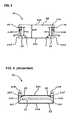
- FIG. 1is a perspective view of the first connector body (first connector element) of the connector according to the present invention
- FIG. 2is a perspective view of the second connector body (second connector element) of the connector according to the present invention.
- FIG. 3is a schematic top view of the first connector body
- FIG. 4schematically shows the cross section of the first connector body taken along the line 44 in FIG. 3 ;
- FIG. 5is a schematic top view of the second connector body
- FIG. 6schematically shows the cross section of the second connector body taken along the line 6 - 6 in FIG. 5 ;
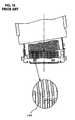
- FIG. 7illustrates the second connector body which is combined with a plug assembly
- FIG. 8illustrates the manner of connecting the second connector body to the first connector body
- FIG. 9illustrates the first connector body to which the second connector body (not seen) is connected.
- FIG. 10illustrates the manner of oblique connection of the first and second connector elements in prior art connector.
- the connector of the present inventionis comprised of a first connector body 20 (a receptacle side connector element) and a second connector body 40 (a plug side connector element).
- the first and second connector bodies 20 and 40comprise respectively a relatively flat box shape shell 22 and 42 made of a metal and include therein a plurality of pins or elongated electrodes, which are collectively referred to by the reference numerals 24 and 44 respectively, and an insulating material (not shown) is filled therein so as to positionally secure the pins 24 and 44 .
- the shell 22 of the first connector body 20comprises, as best seen from FIG. 4 , a top shell plate 22 A and a bottom shell plate 22 B as well as side shell plates 22 C, thus forming a box shape that has a predetermined depth 22 D (see FIG. 3 ) that extends from the front edge 20 A to the rear edge 20 B of the first connector body 20 .
- the pins 24 of the first connector body 20are arranged parallel to the direction of the depth 22 D.
- the shell 22 of the first connector 20is formed in its top shell plate 22 A with engagement projections 30 .
- Each of the projections 30is formed by cutting the top shell plate 22 A in an angled C shape, and the resulting tongue pieces 22 E are bent inward toward the interior of the shell 22 .
- the tongue pieces 22 Eare in the shape of elongated parts of the shell 22 that extend in the direction of the depth 22 D of the first connector body 20 , and they are parallel to the side shell plates 22 C of the first connector body 20 or to the side edges 22 A′ of the top shell plate 22 A.
- the tongue pieces 22 Eare bent at locations of distance 22 W from the side shell plates 22 C or from the side edges 22 A′ of the first connector body 20 to make the engagement projections 30 .
- the engagement projections 30are provided with a space of a distance L apart from the front edge 20 A of the first connector body 20 .
- the front ends 32 of the engagement projections 30are spaced apart from the front edge 20 A of the first connector body 20 .
- the engagement projections 30have a length 30 L which is, in the shown embodiment, about two third the depth 22 D of the first connector body 20 .
- the shell 42 of the second connector body 40comprises, as best seen from FIG. 6 , a top shell plate 42 A and a bottom shall shell plate 42 B as well as side shell plates 42 C, thus forming a box shape with a predetermined depth 42 D (see FIG. 6 ) that extends from the front edge 40 A to the rear edge 40 B of the second connector body 40 .
- the overall size of the shell 42 of the second connector 42is slightly smaller than the shell 22 of the first connector body 20 so that the second connector body 40 is fitted in the first connector body 20 from the front side of the first connector body 20 .
- the pins 44 of the second connector body 40are arranged so be parallel to the direction of the depth 42 D.
- the shell 42 of the second connector body 40is formed in its top shell plate 42 A with engagement slits 50 .
- Each of the engagement slits 50is formed by cutting away parts of the top shell plate 42 A linearly so that the engagement slits 50 are parallel to and adjacent to the side plates 42 C or to side edges 42 A′ of the top shell plate 42 A.
- An alternate constructionwould be to mold the slits 50 into the shell 42 when the shell 42 is made.
- the engagement slits 50are provided so as to extend in the direction of depth 42 D of the shell 42 of the second connector body 40 .
- the front end ends 52 of the engagement slits 50are on the front edge 40 A of the second connector body 40 .
- the engagement slits 50have a length 50 L which is, in the shown embodiment, about two thirds of the depth 42 D of the second connector body 40 and is slightly larger in length than the engagement projections 30 of the first connector body 20 .
- the engagement slits 50are opened at locations of distance 42 W from the side shell plates 42 C or from the side edges 42 A′ of the top shell plate 42 A of the second connector body 40 , the distance 42 W being substantially the same as the distance 22 W of the engagement projections 30 of the first connector body 20 .
- the engagement slits 50positionally correspond to the engagement projections 30 of the first connector body 20 .
- the width W of the engagement slits 50is substantially the same as (or slightly larger than) the thickness of the tongue pieces 22 E (engagement projections 30 ) which is the thickness of the metal material of the shell 22 of the first connector body 20 .
- the reference numerals 60 shown in FIG. 2are raised springy holders formed by notching the top shell plate 42 A of the second connector body 40 and raised outwardly.
- the first and second connector bodies 20 and 40 structured as described aboveare connected by way of mating together at the front ends of the shells 22 and 42 .
- the second connector body 40which is attached at its rear edge 40 B to, typically, a plug assembly 60 70 that is connected to, for instance, an electrical cable (not shown), is held by hand, and then it is brought to the vicinity of the first connector body 20 which is installed in a casing body of, for instance, a PDA (not shown).
- the front edge 40 A of the second connector body 40which is a plug side connector element, is set so as to face the front edge 20 A of the first connector body 20 , which is a receptacle side connector element, so that the first and second connector bodies 20 and 40 are aligned in the direction of the depth thereof (which brings an alignment of the pins 24 and 44 installed in such connector bodies 20 and 40 ).
- the engagement projections 30 of the first connector body 20 and the engagement slits 50 of the second connector body 40are also aligned on imaginary straight lines.
- the second connector body 40is pushed into the first connector body 20 as shown by arrow in FIG. 8 .
- the outer surfaces of the shell 42 of the second connector body 40are guided by the inner surfaces of the shells 22 of the first connector body 20 .
- the engagement slits 50 of the second connector body 40come into engagement with the engagement projections 30 of the first connector body 20 .
- the sliding movement of the second connector body 40 in the depth 22 D of and toward the rear edge 20 B of the first connector body 20is guided by the engagement projections 30 .
- the second connector body 40is thus pushed into the first connector body 20 straight with the pins inside both connector bodies aligned straight as well and connected to the first connector body 20 (see FIG. 9 , in which the second connector body 40 is unseen since it is inside the first connector body 20 ).
- the second connector body 40is held inside the first connector body 20 by the raised springy holders 60 that press against the inside surface of the top shell plate 22 A of the first connector body 20 .
- each engagement slit 50is substantially the same as (or slightly larger than) the thickness of the engagement projection 30 , and thus the engagement projections 30 have substantially no space for play in the direction perpendicular to the direction of the length of the engagement slits 50 or to the direction of the connecting direction of the first and second connector bodies 20 and 40 . Accordingly, the engagement slits 50 of the second connector body 40 make no lateral movements during the sliding movement, keeping the straight alignment obtained by the engaged engagement projections 30 and engagement slits 50 .
Landscapes
- Engineering & Computer Science (AREA)
- Manufacturing & Machinery (AREA)
- Details Of Connecting Devices For Male And Female Coupling (AREA)
Abstract
Description
Notice: More than one reissue application has been filed for the reissue of U.S. Pat. No. 6,776,660. The reissue applications are application Ser. Nos. 11/334,820 and 29/318,045, (the present application) all of which are continuation reissues of Ser. No. 11/334,820.
1. Field of the Invention
The present invention relates to a connector and more particularly to an electrical connector used in, for instance, small size electrical appliances.
2. Prior Art
In for instance, computer related electronic appliances, the electrical connections including connections to an AC adapter, to interfaces, etc. are made in many different ways. Such electrical connections are typically made by connectors that substantially comprise a receptacle (female) side connector element and a plug (male) side connector element that is brought into the receptacle side connector and coupled thereto for making electrical connection in between so that pin-shaped electrodes installed in the connector elements are connected.
More specifically, connectors typically include in their metal shells a plurality of pins (or terminals) that are arranged in parallel in their longitudinal directions and positionally secured by insulator material such as polyamide, LCP (liquid crystalline polymer), etc. The pins in the receptacle and plug side connector elements are spacedly arranged side by side in the direction in which the connector elements are mated together.
Upon making connection of the plug side connector element into the receptacle side connector element, it is necessary that respective pins in two connector elements be aligned to be on a straight line. In other words, it is necessary to avoid the connector elements from being oblique to each other when they are brought together at their front edges for connection. If the plug side connector element in an oblique posture with reference to the receptacle side connector element, as shown inFIG. 10 , is pushed into the receptacle side connector element, an irregular pin connection is made (as at100) as seen from the enlarged view shown in the circle inFIG. 10 , and this would cause several problems including short-circuiting.
In addition, when the plug side connector element is connected to the receptacle connector element in a slanted posture (which can easily occur when there is size differences between the receptacle and plug side connector elements), removing of the plug side connector element from the receptacle side connector element is not easily done and occasionally requires forcible and repeated twists on the shell of the plug side connector element This would cause damage to the pins and the shells of both connector elements.
Thus, though pin alignment is essential when connection is made between the two connector elements, such a pin alignment is not obtained easily and this difficulty can occur often when the connector is small in size and used in small size electrical devices such as a personal digital assistance (PDA), digital cameras, camcorders, etc.
Accordingly, the object of the present invention is to provide an electrical connector that allows accurate and secure connections or coupling between connector elements to be made easily without causing pin or electrode misalignment.
The above object is accomplished by a unique structure of the present invention for a connector that comprises a first connector element and a second connector element that are coupled together when the second connector element is fitted in the first connector element, and in the present invention:
- the first connector element is formed with an engagement projection that extends in the direction of the depth of the first connector element, the front end of the engagement projection being spacedly apart from the front edge of the first connector element; and
- the second connector element is formed with an engagement slit or slot that extends in the direction of the depth of the second connector element so that the engagement slit receives therein the engagement projection of first connector element when the first and second connector elements are connected.
With the structure above, upon connecting the second connector element to the first connector element, the front end of the engagement slit of the second connector element engages with the engagement projection of the fist connecting element after the front end of the engagement slit has advanced the distance between the front edge of the first connector element and the front end of the engagement projection, and then the second connector element is pushed all the way to back of the first connector element in the depth of the first connector element while being guided by the engagement slit engaging with the engagement projection. Accordingly, even when the second connector element is obliquely pushed into the first connector element at the initial stage of coupling process, such oblique posture is corrected by the engagement projection of the first connector element as the second connector element is pushed and advanced to the back of the first connector element, and a connection between the first and second connector elements with the pins (electrodes) inside both of them being aligned straight can be made assuredly.
The connector of the present invention is comprised of a first connector body20 (a receptacle side connector element) and a second connector body40 (a plug side connector element).
As seen fromFIGS. 1 and 2 , the first andsecond connector bodies box shape shell reference numerals pins
Theshell 22 of thefirst connector body 20 comprises, as best seen fromFIG. 4 , atop shell plate 22A and abottom shell plate 22B as well asside shell plates 22C, thus forming a box shape that has apredetermined depth 22D (seeFIG. 3 ) that extends from thefront edge 20A to the rear edge20B of thefirst connector body 20. Thepins 24 of thefirst connector body 20 are arranged parallel to the direction of thedepth 22D.
Theshell 22 of thefirst connector 20 is formed in itstop shell plate 22A withengagement projections 30. Each of theprojections 30 is formed by cutting thetop shell plate 22A in an angled C shape, and the resultingtongue pieces 22E are bent inward toward the interior of theshell 22. Thetongue pieces 22E are in the shape of elongated parts of theshell 22 that extend in the direction of thedepth 22D of thefirst connector body 20, and they are parallel to theside shell plates 22C of thefirst connector body 20 or to theside edges 22A′ of thetop shell plate 22A.
Thetongue pieces 22E are bent at locations ofdistance 22W from theside shell plates 22C or from theside edges 22A′ of thefirst connector body 20 to make theengagement projections 30. Theengagement projections 30 are provided with a space of a distance L apart from thefront edge 20A of thefirst connector body 20. In other words, the front ends32 of theengagement projections 30 are spaced apart from thefront edge 20A of thefirst connector body 20. Theengagement projections 30 have alength 30L which is, in the shown embodiment, about two third thedepth 22D of thefirst connector body 20.
On the other hand, theshell 42 of thesecond connector body 40 comprises, as best seen fromFIG. 6 , atop shell plate 42A and a bottom shall shell plate42B as well asside shell plates 42C, thus forming a box shape with apredetermined depth 42D (seeFIG. 6 ) that extends from thefront edge 40A to the rear edge40B of thesecond connector body 40. The overall size of theshell 42 of thesecond connector 42 is slightly smaller than theshell 22 of thefirst connector body 20 so that thesecond connector body 40 is fitted in thefirst connector body 20 from the front side of thefirst connector body 20. Thepins 44 of thesecond connector body 40 are arranged so be parallel to the direction of thedepth 42D.
Theshell 42 of thesecond connector body 40 is formed in itstop shell plate 42A withengagement slits 50. Each of theengagement slits 50 is formed by cutting away parts of thetop shell plate 42A linearly so that theengagement slits 50 are parallel to and adjacent to theside plates 42C or toside edges 42A′ of thetop shell plate 42A. An alternate construction would be to mold theslits 50 into theshell 42 when theshell 42 is made. Theengagement slits 50 are provided so as to extend in the direction ofdepth 42D of theshell 42 of thesecond connector body 40. In other words, the front end ends52 of theengagement slits 50 are on thefront edge 40A of thesecond connector body 40. Theengagement slits 50 have a length50L which is, in the shown embodiment, about two thirds of thedepth 42D of thesecond connector body 40 and is slightly larger in length than theengagement projections 30 of thefirst connector body 20.
Theengagement slits 50 are opened at locations ofdistance 42W from theside shell plates 42C or from theside edges 42A′ of thetop shell plate 42A of thesecond connector body 40, thedistance 42W being substantially the same as thedistance 22W of theengagement projections 30 of thefirst connector body 20. Thus, the engagement slits50 positionally correspond to theengagement projections 30 of thefirst connector body 20. The width W of theengagement slits 50 is substantially the same as (or slightly larger than) the thickness of thetongue pieces 22E (engagement projections30) which is the thickness of the metal material of theshell 22 of thefirst connector body 20.
Thereference numerals 60 shown inFIG. 2 are raised springy holders formed by notching thetop shell plate 42A of thesecond connector body 40 and raised outwardly.
The first andsecond connector bodies shells
More specifically, as shown inFIG. 7 , thesecond connector body 40, which is attached at its rear edge40B to, typically, aplug assembly 60 70 that is connected to, for instance, an electrical cable (not shown), is held by hand, and then it is brought to the vicinity of thefirst connector body 20 which is installed in a casing body of, for instance, a PDA (not shown).
Thefront edge 40A of thesecond connector body 40, which is a plug side connector element, is set so as to face thefront edge 20A of thefirst connector body 20, which is a receptacle side connector element, so that the first andsecond connector bodies pins such connector bodies 20 and40). In this positioning, since thedistances second connector bodies engagement projections 30 of thefirst connector body 20 and the engagement slits50 of thesecond connector body 40 are also aligned on imaginary straight lines.
Then, thesecond connector body 40 is pushed into thefirst connector body 20 as shown by arrow inFIG. 8 . During the initial pushing movement, the outer surfaces of theshell 42 of thesecond connector body 40 are guided by the inner surfaces of theshells 22 of thefirst connector body 20. After advancing the distance L which is the distance from thefront edge 20A to the front ends32 of theengagement projections 30 in thefirst connector body 20, the engagement slits50 of thesecond connector body 40 come into engagement with theengagement projections 30 of thefirst connector body 20. As a result, the sliding movement of thesecond connector body 40 in thedepth 22D of and toward the rear edge20B of thefirst connector body 20 is guided by theengagement projections 30. Thesecond connector body 40 is thus pushed into thefirst connector body 20 straight with the pins inside both connector bodies aligned straight as well and connected to the first connector body20 (seeFIG. 9 , in which thesecond connector body 40 is unseen since it is inside the first connector body20). Thesecond connector body 40 is held inside thefirst connector body 20 by the raisedspringy holders 60 that press against the inside surface of thetop shell plate 22A of thefirst connector body 20.
The width W of each engagement slit50 is substantially the same as (or slightly larger than) the thickness of theengagement projection 30, and thus theengagement projections 30 have substantially no space for play in the direction perpendicular to the direction of the length of the engagement slits50 or to the direction of the connecting direction of the first andsecond connector bodies second connector body 40 make no lateral movements during the sliding movement, keeping the straight alignment obtained by the engagedengagement projections 30 and engagement slits50.
As a result, even when thesecond connector body 40 is slanted with reference to thefirst connector body 20 during the initial connecting stage, such a slanted positional relationship is automatically corrected to a straight relationship as thesecond connector body 40 is pushed into deep in thefirst connector body 20, and a snug and secure engagement of the first andsecond connector bodies second connector bodies engagement projections 30 and the engagement slits50 are formed near the side edges22A′ and42A′ of the first andsecond connector bodies connector bodies
Claims (28)
1. A connector comprising a first connector element and a second connector element that are coupled together, wherein
said first and second connector elements are each formed with a metallic shell;
said first connector element is formed with an engagement projection that projects toward an interior of said first connector element and extends in a direction of depth of said first connector element, a front end of said engagement projection being spaced apart from a front edge of said connector element by a predetermined distance;
said engagement projection is formed by cutting a C-shape slit in a top surface of said metallic shell of said first connector element and bending a tongue formed downwardly; and
said second connector element is formed with an engagement slit in said metallic shell that extends in a direction of depth of said metallic shell of said second connector for engaging with said engagement projection formed in said metallic shell of said first connector element.
2. The connector according toclaim 1 , wherein said engagement projection is provided at two locations of said first connector element so as to be parallel to side edges of said first connector element, and said engagement slit is provided at two location of said second connector element so as to be parallel to side edges of said second connector element and to correspond to said two locations of said engagement projections of said first connector element.
3. The connector according toclaim 1 , wherein said engagement projection has a predetermined length in said depth direction and said engagement slit has a predetermined length in said depth direction which is at said predetermined length of said engagement projection.
4. An electrical connector comprising:
a receptacle connector element having a first metallic shell and adapted to be coupled to a plug connector element having a second metallic shell, the first shell comprising a top plate, a bottom plate, a first side and a second side and having a width W and a depth D, the first and second sides being small relative to the top and bottom plates making the first shell substantially flat;
first and second engagement projections formed in the top plate of the first shell that project toward an interior of the receptacle connector element and extend in a direction of a depth of the receptacle connector element, a front end of the first and second engagement projections being spaced apart from a front edge of the receptacle connector element by a predetermined distance, the engagement projections being formed by cutting a C-shape slit in a top surface of the first shell and bending a tongue formed downwardly;
an array of electrodes disposed within the first shell and extending in a direction of the depth D between the first and second engagement projections such that there are no electrodes between an engagement projection and its respective side, the array of electrodes being positioned to provide for an insertion cavity around the array of electrodes in an interior of the shell;
wherein the first and second engagement projections in the first shell are adapted to engage with first and second engagement slits formed in a top plate of the second shell, the first and second engagement slits starting from a front edge of the top plate and extending in a direction of the depth D.
5. An electrical connector comprising:
a receptacle connector element having a first shell and adapted to be coupled to a plug connector element having a second shell, the first shell comprising a top plate, a bottom plate, a first side and a second side and having a width W and a depth D, the first and second sides being small relative to the top and bottom plates making the first shell substantially flat;
first and second engagement projections formed in the top plate of the first shell that project toward an interior of the receptacle connector element and extend in a direction of a depth of the receptacle connector element, a front end of the first and second engagement projections being spaced apart from a front edge of the receptacle connector element by a predetermined distance;
an array of electrodes disposed within the first shell and extending in a direction of the depth D between the first and second engagement projections such that there are no electrodes between an engagement projection and its respective side, the array of electrodes being positioned to provide for an insertion cavity around the array of electrodes in an interior of the shell;
wherein the first and second engagement projections in the first shell are adapted to engage with first and second engagement slits formed in a top plate of the second shell.
6. The electrical connector of claim 5 wherein each of the projections is in the shape of a tongue that is bent toward the interior of the shell.
7. The electrical connector of claim 5 wherein the tongue is formed by cutting an angled C shape into the top plate of the shell.
8. The electrical connector of claim 5 wherein each of the projections has a length that is about two thirds of the depth D of the shell.
9. The electrical connector of claim 5 wherein the top plate and the bottom plate are made of metal.
10. An electrical receptacle connector comprising:
a body having a top plate, a bottom plate, a first side and a second side, the body having a width W and a depth D, wherein the first and second sides are smaller relative to the top and bottom plates providing a substantially flat body;
an array of electrodes extending in the direction of the depth D inside the body and positioned to provide for an insertion cavity around the array of electrodes in an interior of the body; and
first and second projections extending, in a first direction, from the top plate toward the interior of the body and extending, in a second direction, along the depth D, the first projection being disposed at a distance S1 from the first side of the body and the second projection being disposed at a distance S2 from the second side of the body, wherein S1 and S2 are about the same,
wherein, the array of electrodes is disposed between the first and second projections such that there are no electrodes between a projection and its respective side, and
wherein, the first and second projections facilitate engagement alignment when the receptacle connector mates with a corresponding plug connector.
11. The receptacle connector of claim 10 wherein the plurality of projections start at a distance L from a front edge of the first plate.
12. The receptacle connector of claim 10 wherein each of the projections is in the shape of a tongue that is bent toward the interior of the body.
13. The receptacle connector of claim 12 wherein the tongue is formed by cutting an angled C shape into the top plate of the body.
14. The receptacle connector of claim 10 wherein each of the projections has a length that is about two thirds of the depth D of the body.
15. The receptacle connector of claim 10 wherein the top plate and the bottom plate are made of metal.
16. The receptacle connector of claim 10 further comprising a casing wherein the body is housed, the casing comprising an electronic device.
17. The receptacle connector of claim 16 wherein the electronic device is a personal digital assistant.
18. The receptacle connector of claim 10 wherein the body is sized to allow insertion of a body of a corresponding plug connector therein.
19. An electrical receptacle connector comprising:
a body having a top plate, a bottom plate, a first side and a second side, the body having a width W and a depth D, wherein the first and second sides are smaller relative to the top and bottom plates providing a substantially flat body;
an array of electrodes extending in the direction of the depth D inside the body; and
one or more projections extending, in a first direction, from the top plate toward the interior of the body and extending, in a second direction, along the depth D, each of the one or more projections being disposed a predetermined distance from the first or second side,
wherein the array of electrodes is disposed such that there are no electrodes between a projection and its nearest side, and
wherein the one or more projections guide the insertion process when the electrical connector mates with another connector.
20. The electrical receptacle connector of claim 19 wherein the array of electrodes are positioned to provide for an insertion cavity around the array of electrodes in an interior of the body.
21. The electrical receptacle connector of claim 19 wherein the one or more projections start at a distance L from a front edge of the first plate.
22. The electrical receptacle connector of claim 19 wherein the one or more projections comprises a first projection at a distance S1 from the first side of the body and a second projection at a distance S2 from the second side of the body, wherein S1 and S2 are about the same.
23. The electrical receptacle connector of claim 22 wherein the array of electrodes is formed between the first projection and the second projection.
24. The electrical receptacle connector of claim 22 wherein each of the outermost electrodes of the array of electrodes is spaced away from its respective side by a distance that is no less than S1 or S2.
25. The electrical receptacle connector of claim 19 wherein each of the one or more projections is in the shape of a tongue that is bent toward the interior of the body.
26. The electrical receptacle connector of claim 25 wherein the tongue is formed by cutting an angled C shape into the top plate of the body.
27. The electrical receptacle connector of claim 19 wherein each of the one or more projections has a length that is about two thirds of the depth D of the body.
28. The electrical receptacle connector of claim 19 wherein the top plate and the bottom plate are made of metal.
Priority Applications (1)
| Application Number | Priority Date | Filing Date | Title |
|---|---|---|---|
| US12/613,482USRE43796E1 (en) | 2003-04-30 | 2009-11-05 | Receptacle connector |
Applications Claiming Priority (2)
| Application Number | Priority Date | Filing Date | Title |
|---|---|---|---|
| US10/426,218US6776660B1 (en) | 2003-04-30 | 2003-04-30 | Connector |
| US12/613,482USRE43796E1 (en) | 2003-04-30 | 2009-11-05 | Receptacle connector |
Related Parent Applications (1)
| Application Number | Title | Priority Date | Filing Date |
|---|---|---|---|
| US10/426,218ReissueUS6776660B1 (en) | 2003-04-30 | 2003-04-30 | Connector |
Publications (1)
| Publication Number | Publication Date |
|---|---|
| USRE43796E1true USRE43796E1 (en) | 2012-11-06 |
Family
ID=32850714
Family Applications (4)
| Application Number | Title | Priority Date | Filing Date |
|---|---|---|---|
| US10/426,218CeasedUS6776660B1 (en) | 2003-04-30 | 2003-04-30 | Connector |
| US11/334,820Expired - LifetimeUSRE41224E1 (en) | 2003-04-30 | 2006-01-18 | Connector |
| US12/613,482Expired - LifetimeUSRE43796E1 (en) | 2003-04-30 | 2009-11-05 | Receptacle connector |
| US12/613,474Expired - LifetimeUSRE43780E1 (en) | 2003-04-30 | 2009-11-05 | Plug connector |
Family Applications Before (2)
| Application Number | Title | Priority Date | Filing Date |
|---|---|---|---|
| US10/426,218CeasedUS6776660B1 (en) | 2003-04-30 | 2003-04-30 | Connector |
| US11/334,820Expired - LifetimeUSRE41224E1 (en) | 2003-04-30 | 2006-01-18 | Connector |
Family Applications After (1)
| Application Number | Title | Priority Date | Filing Date |
|---|---|---|---|
| US12/613,474Expired - LifetimeUSRE43780E1 (en) | 2003-04-30 | 2009-11-05 | Plug connector |
Country Status (3)
| Country | Link |
|---|---|
| US (4) | US6776660B1 (en) |
| CN (4) | CN1284279C (en) |
| TW (1) | TWI258252B (en) |
Cited By (1)
| Publication number | Priority date | Publication date | Assignee | Title |
|---|---|---|---|---|
| US20130095676A1 (en)* | 2011-10-12 | 2013-04-18 | Hon Hai Precision Industry Co., Ltd. | Electrical connector assembly with compact configuration |
Families Citing this family (52)
| Publication number | Priority date | Publication date | Assignee | Title |
|---|---|---|---|---|
| US7627343B2 (en) | 2003-04-25 | 2009-12-01 | Apple Inc. | Media player system |
| US7441062B2 (en) | 2004-04-27 | 2008-10-21 | Apple Inc. | Connector interface system for enabling data communication with a multi-communication device |
| US7634605B2 (en) | 2004-04-27 | 2009-12-15 | Apple Inc. | Method and system for transferring stored data between a media player and an accessory |
| US7529871B1 (en) | 2004-04-27 | 2009-05-05 | Apple Inc. | Communication between an accessory and a media player with multiple protocol versions |
| US7826318B2 (en) | 2004-04-27 | 2010-11-02 | Apple Inc. | Method and system for allowing a media player to transfer digital audio to an accessory |
| US7673083B2 (en) | 2004-04-27 | 2010-03-02 | Apple Inc. | Method and system for controlling video selection and playback in a portable media player |
| US7441058B1 (en) | 2006-09-11 | 2008-10-21 | Apple Inc. | Method and system for controlling an accessory having a tuner |
| US7526588B1 (en) | 2004-04-27 | 2009-04-28 | Apple Inc. | Communication between an accessory and a media player using a protocol with multiple lingoes |
| US7895378B2 (en)* | 2004-04-27 | 2011-02-22 | Apple Inc. | Method and system for allowing a media player to transfer digital audio to an accessory |
| US7529870B1 (en) | 2004-04-27 | 2009-05-05 | Apple Inc. | Communication between an accessory and a media player with multiple lingoes |
| US8117651B2 (en) | 2004-04-27 | 2012-02-14 | Apple Inc. | Method and system for authenticating an accessory |
| US7293122B1 (en) | 2004-04-27 | 2007-11-06 | Apple Inc. | Connector interface system facilitating communication between a media player and accessories |
| US7797471B2 (en)* | 2004-04-27 | 2010-09-14 | Apple Inc. | Method and system for transferring album artwork between a media player and an accessory |
| US7529872B1 (en) | 2004-04-27 | 2009-05-05 | Apple Inc. | Communication between an accessory and a media player using a protocol with multiple lingoes |
| USD519458S1 (en)* | 2004-08-24 | 2006-04-25 | Cheng Uei Precision Industry Co., Ltd. | Plug connector |
| USD518439S1 (en)* | 2004-12-20 | 2006-04-04 | Cheng Uei Precision Industry Co., Ltd. | Plug connector |
| US7525216B2 (en) | 2005-01-07 | 2009-04-28 | Apple Inc. | Portable power source to provide power to an electronic device via an interface |
| US8238971B2 (en) | 2005-01-07 | 2012-08-07 | Apple Inc. | Accessory detection to minimize interference with wireless communication |
| US7823214B2 (en) | 2005-01-07 | 2010-10-26 | Apple Inc. | Accessory authentication for electronic devices |
| US8006019B2 (en) | 2006-05-22 | 2011-08-23 | Apple, Inc. | Method and system for transferring stored data between a media player and an accessory |
| US7415563B1 (en) | 2006-06-27 | 2008-08-19 | Apple Inc. | Method and system for allowing a media player to determine if it supports the capabilities of an accessory |
| US7751198B2 (en) | 2006-09-11 | 2010-07-06 | Apple Inc. | Multi-connector assembly |
| US7558894B1 (en) | 2006-09-11 | 2009-07-07 | Apple Inc. | Method and system for controlling power provided to an accessory |
| US7900068B2 (en)* | 2006-09-14 | 2011-03-01 | Hon Hai Precision Industry Co., Ltd. | Mobile multi-media interface and power pack for portable entertainment devices |
| US7429197B2 (en)* | 2006-10-31 | 2008-09-30 | Monster Cable Products, Inc. | 30-pin connector |
| USD552554S1 (en)* | 2006-12-19 | 2007-10-09 | Cheng Uei Precision Industry Co., Ltd. | Receptacle connector |
| US7540788B2 (en)* | 2007-01-05 | 2009-06-02 | Apple Inc. | Backward compatible connector system |
| TWM348352U (en)* | 2008-06-18 | 2009-01-01 | Chief Land Electronic Co Ltd | Electrical connector with alignment structure and assembly thereof |
| US8208853B2 (en) | 2008-09-08 | 2012-06-26 | Apple Inc. | Accessory device authentication |
| US8238811B2 (en) | 2008-09-08 | 2012-08-07 | Apple Inc. | Cross-transport authentication |
| US8507796B2 (en)* | 2009-07-15 | 2013-08-13 | Luxi Electronics Corp. | Ribbon Cables |
| US8506327B2 (en)* | 2009-09-30 | 2013-08-13 | Eric Jol | Portable electronic devices with sealed connectors |
| CN201708279U (en)* | 2009-10-12 | 2011-01-12 | 富士康(昆山)电脑接插件有限公司 | electrical connector |
| US8246383B2 (en)* | 2010-03-19 | 2012-08-21 | Apple Inc. | Sealed connectors for portable electronic devices |
| US20110226823A1 (en)* | 2010-03-19 | 2011-09-22 | Jasa Roddy J | Retractable Lanyard for Securing Personal Multimedia Devices |
| US9202527B2 (en) | 2010-05-21 | 2015-12-01 | Seagate Technology, Llc | Modular interface communications with a storage cartridge |
| US8485839B2 (en) | 2010-05-21 | 2013-07-16 | Seagate Technology Llc | Modular interface communications with a storage cartridge |
| US8560031B2 (en) | 2011-03-16 | 2013-10-15 | David B. Barnett | Extending socket for portable media player |
| US8414337B2 (en) | 2011-05-20 | 2013-04-09 | Apple Inc. | Low profile male connector |
| US8659889B2 (en) | 2011-05-20 | 2014-02-25 | Apple Inc. | Docking station for providing digital signage |
| US9274578B2 (en) | 2012-05-09 | 2016-03-01 | Apple Inc. | Enable power from an accessory to a host device based on whether the accessory is able to alter an electrical characteristic of the power path |
| US8683090B2 (en) | 2012-04-19 | 2014-03-25 | Apple Inc. | Methods, systems and apparatus for determining whether an accessory includes particular circuitry |
| JP6133119B2 (en) | 2013-04-25 | 2017-05-24 | 日本航空電子工業株式会社 | Connector assembly |
| CN203589367U (en) | 2013-05-24 | 2014-05-07 | 富士康(昆山)电脑接插件有限公司 | Electric connector combination and electric connector |
| US9357654B2 (en) | 2014-03-03 | 2016-05-31 | Apple Inc. | Low-profile plug with cam and flexible circuit board |
| CN104022396B (en)* | 2014-05-29 | 2016-06-15 | 立讯精密工业(昆山)有限公司 | Electric connector combination |
| US9413117B2 (en)* | 2014-11-24 | 2016-08-09 | Yong Tai Electronic(DONGGUAN) Ltd. | Receptacle |
| US9800703B2 (en) | 2015-11-23 | 2017-10-24 | TecTide Group, LLC | Handling apparatus for portable electronic devices |
| JP6340041B2 (en)* | 2016-07-26 | 2018-06-06 | Smk株式会社 | Electrical connector |
| US10054259B2 (en) | 2016-08-17 | 2018-08-21 | Popsockets Llc | Expanding socket accessory for mobile electronic device |
| JP6605431B2 (en)* | 2016-11-17 | 2019-11-13 | 矢崎総業株式会社 | connector |
| USD928771S1 (en) | 2019-01-07 | 2021-08-24 | Popsockets Llc | Grip and stand accessory for personal electronic device |
Citations (91)
| Publication number | Priority date | Publication date | Assignee | Title |
|---|---|---|---|---|
| US4508756A (en) | 1980-10-08 | 1985-04-02 | Murata Manufacturing Co., Ltd. | Method for inhibiting oxidation of a copper film on ceramic body |
| US4567608A (en) | 1984-03-23 | 1986-01-28 | Electro-Voice, Incorporated | Microphone for use on location |
| US4850899A (en) | 1988-06-20 | 1989-07-25 | Maynard Scott D | Connector for interfacing a disk drive with a computer |
| US5055069A (en) | 1990-06-08 | 1991-10-08 | E. I. Du Pont De Nemours And Company | Connectors with ground structure |
| US5080603A (en) | 1989-08-30 | 1992-01-14 | E. I. Du Pont De Nemours And Company | Mountable connector for cable assembly |
| US5104243A (en) | 1990-04-23 | 1992-04-14 | E. I. Du Pont De Nemours And Company | Device for electro-optical signal conversion |
| US5108313A (en) | 1989-10-05 | 1992-04-28 | E. I. Du Pont De Nemours And Company | Modular connector |
| US5186646A (en) | 1992-01-16 | 1993-02-16 | Pederson William A | Connector device for computers |
| US5235217A (en) | 1991-07-24 | 1993-08-10 | Isb Ltd. | Capacitive press control actuation system |
| US5267881A (en) | 1992-09-24 | 1993-12-07 | Hirose Electric Co., Ltd. | Electrical connector |
| US5277624A (en) | 1991-12-23 | 1994-01-11 | Souriau Et Cie | Modular electrical-connection element |
| US5344335A (en) | 1992-03-03 | 1994-09-06 | The Whitaker Corporation | Latching system for electrical connectors |
| US5425650A (en) | 1993-02-01 | 1995-06-20 | Yazaki Corporation | Inclined engagement prevention structure for connector |
| JPH07176351A (en) | 1990-01-31 | 1995-07-14 | Thomas & Betts Corp <T&B> | Connector assembly |
| US5586893A (en) | 1995-07-17 | 1996-12-24 | Itt Corporation | IC card connector shield grounding |
| US5660558A (en) | 1995-04-04 | 1997-08-26 | Japan Aviation Electronics Industry, Limited | Shielded connector having a shell with integral latch arms |
| EP0805523A2 (en) | 1996-05-03 | 1997-11-05 | Molex Incorporated | Electrical connector latching system |
| US5697817A (en) | 1994-03-26 | 1997-12-16 | Molex Incorporated | Modular jack type connector |
| USD390828S (en) | 1996-01-23 | 1998-02-17 | Sony Corporation | Connector for a computer game |
| US5830001A (en) | 1995-03-31 | 1998-11-03 | Japan Aviation Electronics Industry, Limited | Connector capable of reliably locking a plug connector to a receptacle connector |
| JPH10321302A (en) | 1997-05-23 | 1998-12-04 | Mitsumi Electric Co Ltd | Electric connector |
| JPH10334993A (en) | 1997-05-29 | 1998-12-18 | Japan Aviation Electron Ind Ltd | Connector device |
| US5901049A (en) | 1996-11-29 | 1999-05-04 | Siemens Aktiengesellschaft | Two-tiered plug for two chip cards |
| US5934942A (en) | 1997-12-30 | 1999-08-10 | Molex Incorporated | Shielded electrical connector assembly |
| US5975957A (en) | 1997-04-11 | 1999-11-02 | Molex Incorporated | I/O connector with resilient connecting means |
| US5990758A (en) | 1994-12-22 | 1999-11-23 | Masprodenkoh Kabushikikaisha | High-frequency signal branching device |
| US6053773A (en) | 1997-08-26 | 2000-04-25 | Hon Hai Precision Ind. Co., Ltd. | Electrical input/output connector |
| JP2000223215A (en) | 1999-01-27 | 2000-08-11 | Mitsumi Electric Co Ltd | Small-sized connector |
| JP2000223216A (en) | 1999-01-27 | 2000-08-11 | Mitsumi Electric Co Ltd | Small-sized connector |
| JP2000223218A (en) | 1999-01-27 | 2000-08-11 | Mitsumi Electric Co Ltd | Small-sized connector |
| US6116943A (en) | 1998-06-30 | 2000-09-12 | The Whitaker Corporation | Modular plug having a circuit board |
| US6154798A (en) | 1996-07-19 | 2000-11-28 | Compaq Computer Corporation | Computer system implementing hot docking and undocking capabilities by employing a local bus arbiter idle stats in which the arbiter is parked on a first input/output bus portion |
| CN1282124A (en) | 1999-07-26 | 2001-01-31 | 日本压着端子制造株式会社 | Connector for printed wiring board |
| US6203345B1 (en) | 1999-11-09 | 2001-03-20 | Hon Hai Precision Ind. Co., Ltd. | Flexible circuit connector |
| US6206480B1 (en) | 1997-03-25 | 2001-03-27 | Eric Thompson | Mobile computing and communication system |
| JP2001196133A (en) | 2000-01-11 | 2001-07-19 | Sony Corp | Fitting method of connector and connector by this fitting method |
| US6267623B1 (en) | 1997-10-03 | 2001-07-31 | Japan Aviation Electronics Industry, Limited | Electrical connector with a mating portion defined by a metallic shell |
| JP2001230021A (en) | 2000-02-17 | 2001-08-24 | Yazaki Corp | connector |
| US6319061B1 (en) | 2000-11-23 | 2001-11-20 | Hon Hai Precision Ind. Co., Ltd . | Pair of shielded electrical connectors with a grounding element therebetween |
| US6322396B1 (en) | 2000-10-13 | 2001-11-27 | L&K Precision Industry Co., Ltd. | Modular communication connector |
| US20020010759A1 (en) | 1999-12-30 | 2002-01-24 | Hitson Bruce L. | System and method for multimedia content composition and distribution |
| US6344727B1 (en) | 2001-03-05 | 2002-02-05 | Motorola, Inc. | Charger having a data store and data link |
| US20020029303A1 (en) | 2000-08-25 | 2002-03-07 | Nguyen Michael Anh | Reconfigurable communication interface and method therefor |
| US6356084B1 (en) | 1998-03-31 | 2002-03-12 | David R. Levine | Audio testing system |
| US6354713B1 (en) | 2000-06-09 | 2002-03-12 | Arista Enterprises Inc. | Light apparatus for illuminating a compact computer video screen |
| DE10104288C1 (en) | 2001-01-30 | 2002-04-04 | Karl Lumberg Gmbh & Co Kg | Electric jack plug connector e.g. for input/output interface of miniature computer or mobile telephone, has spring locking tongues provided by spring plate acting as clip at front end of lead cable plug |
| US20020065074A1 (en) | 2000-10-23 | 2002-05-30 | Sorin Cohn | Methods, systems, and devices for wireless delivery, storage, and playback of multimedia content on mobile devices |
| US20020103008A1 (en) | 2001-01-29 | 2002-08-01 | Rahn Michael D. | Cordless communication between PDA and host computer using cradle |
| US6431915B1 (en) | 2001-09-10 | 2002-08-13 | Hon Hai Precision Ind. Co., Ltd. | RF cable connector assembly for preventing mis-mating |
| US20020115480A1 (en) | 2001-02-13 | 2002-08-22 | Huang Chih Chen | Adapter set |
| US6454592B2 (en) | 1999-12-21 | 2002-09-24 | Japan Aviation Electronics Industry, Limited | Connector with an improved guide portion for guiding connection the connector and an object to be connected thereto |
| US6461173B1 (en) | 1999-07-19 | 2002-10-08 | Japan Aviation Electronics Industry Limited | Hot-plug connector small in size and excellent in contact-flatness and method of manufacturing the same |
| US6464542B1 (en) | 2001-07-19 | 2002-10-15 | Hon Hai Precision Ind. Co., Ltd. | Connector assembly having small profile |
| US20020151327A1 (en) | 2000-12-22 | 2002-10-17 | David Levitt | Program selector and guide system and method |
| US6468110B2 (en) | 2000-04-17 | 2002-10-22 | Japan Aviation Electronics Industry, Limited | Shielded-cable connector improved in transmission characteristics |
| US20020156546A1 (en) | 2001-01-29 | 2002-10-24 | Koninklijke Philips Electronics N.V. | Method, wireless MP3 player and system for downloading MP3 files from the internet |
| US6478603B1 (en) | 2001-12-24 | 2002-11-12 | Hon Hai Precision Ind. Co., Ltd. | Electrical connector with mechanically reinforced blind mating guides |
| US6485328B1 (en) | 2001-12-19 | 2002-11-26 | Hon Hai Precision Ind. Co., Ltd. | Header connector with shell |
| US20030008553A1 (en) | 2001-07-06 | 2003-01-09 | Oleynick Gary J. | Universal serial bus electrical connector |
| US20030028664A1 (en) | 2001-08-02 | 2003-02-06 | Kaijun Tan | Method and system for secure distribution and utilization of data over a network |
| US6524119B2 (en) | 2000-06-26 | 2003-02-25 | Japan Aviation Electronics Industry, Limited | Connector adapted to handling of different kinds of signals including high-speed signals |
| US20030073432A1 (en) | 2001-10-16 | 2003-04-17 | Meade, William K. | Mobile computing device with method and system for interrupting content performance among appliances |
| US6570756B2 (en) | 2001-10-10 | 2003-05-27 | Dell Products L.P. | Personal computer system housing and security system |
| US6577877B1 (en) | 2000-02-23 | 2003-06-10 | Motorola, Inc. | Wireless infrared peripheral interface for a communication device |
| US6585540B2 (en) | 2000-12-06 | 2003-07-01 | Pulse Engineering | Shielded microelectronic connector assembly and method of manufacturing |
| US6591085B1 (en) | 2002-07-17 | 2003-07-08 | Netalog, Inc. | FM transmitter and power supply/charging assembly for MP3 player |
| US6607397B1 (en) | 2002-05-30 | 2003-08-19 | Hon Hai Precision Ind. Co., Ltd. | Electrical connector with enhanced mating mechanism |
| US6608264B1 (en) | 2002-03-29 | 2003-08-19 | Afshin Fouladpour | Switchable data and power cable |
| US6616473B2 (en) | 2000-12-19 | 2003-09-09 | Japan Aviation Electronics Industry, Limited | Thin-type electrical connector having a locking function |
| US6619986B1 (en) | 2002-04-19 | 2003-09-16 | Hon Hai Precision Ind. Co., Ltd. | Electrical connector with metal shield |
| US6653813B2 (en) | 2002-03-21 | 2003-11-25 | Thomson Licensing, S.A. | Apparatus and method for the power management of operatively connected modular devices |
| US6728546B1 (en) | 1999-03-23 | 2004-04-27 | Legerity, Inc. | Computer peripheral base station for a cordless telephone |
| US20040090998A1 (en) | 2002-11-12 | 2004-05-13 | Chen Hong-Xi | Portable DVD player system for video/audio and computer systems |
| US6776626B2 (en) | 2002-03-06 | 2004-08-17 | Molex Incorporated | Electrical connector system for mobile phones |
| US6776665B2 (en) | 2002-11-25 | 2004-08-17 | George Ying-Liang Huang | Electrical connector with a transparent insulating jacket |
| US20040186935A1 (en) | 2003-03-18 | 2004-09-23 | Jory Bell | Component for use as a portable computing device and pointing device |
| US6813528B1 (en) | 1998-03-09 | 2004-11-02 | Samsung Electronics Co., Ltd. | Apparatus and method for outputting audio signal of laptop computer coupled with docking station |
| US6816376B2 (en) | 2002-03-06 | 2004-11-09 | Tyco Electronics Corporation | Pluggable electronic module and receptacle with heat sink |
| US20040224638A1 (en) | 2003-04-25 | 2004-11-11 | Apple Computer, Inc. | Media player system |
| US20040235339A1 (en) | 2000-08-22 | 2004-11-25 | Kazuomi Sato | Connector for flat cable |
| US6840807B2 (en) | 2001-09-28 | 2005-01-11 | Yamaichi Electronics Co., Ltd. | Card connector |
| US20050014536A1 (en) | 2003-07-08 | 2005-01-20 | Jeff Grady | Modular adaptor assembly for personal digital appliance |
| US6859854B2 (en) | 2001-07-25 | 2005-02-22 | Bill Kwong | Universal storage interface bus |
| US20050239333A1 (en) | 2002-05-31 | 2005-10-27 | Satoru Watanabe | Connector for memory card and mobile phone with the connector |
| US20060001700A1 (en) | 2004-06-30 | 2006-01-05 | Bertelsen Craig M | Flexible circuit corrosion protection |
| US6991483B1 (en) | 2002-06-11 | 2006-01-31 | Henry Milan | Flash memory drive with quick connector |
| US6997733B2 (en) | 2004-04-09 | 2006-02-14 | Advanced Connectek Inc. | Electrical connector assembly with shroud and positioning device |
| US7004787B2 (en) | 2002-06-11 | 2006-02-28 | Henry Milan | Universal computer cable with quick connectors and interchangeable ends, and system and method utilizing the same |
| US7221284B2 (en) | 2005-04-13 | 2007-05-22 | Mertek Industries, Llc | Networking cable tracer system |
| US7303438B2 (en) | 2004-12-17 | 2007-12-04 | Molex Incorporated | Plug connector with mating protection and alignment means |
| US7396591B2 (en) | 2005-06-22 | 2008-07-08 | Japan Aviation Electronics Industry Limited | Wiring substrate |
Family Cites Families (4)
| Publication number | Priority date | Publication date | Assignee | Title |
|---|---|---|---|---|
| JP2763061B2 (en)* | 1992-11-24 | 1998-06-11 | 矢崎総業株式会社 | Low insertion / extraction force connector |
| WO1997039610A1 (en) | 1996-04-18 | 1997-10-23 | International Business Machines Corporation | Organic-metallic composite coating for copper surface protection |
| US5881454A (en)* | 1996-11-25 | 1999-03-16 | Seagate Technology, Inc. | Method of making single-sided electronic connector |
| US6564009B2 (en) | 1997-05-19 | 2003-05-13 | Sony Corporation | Apparatus for recording and/or reproducing data onto and/or from an optical disk and method thereof |
- 2003
- 2003-04-30USUS10/426,218patent/US6776660B1/ennot_activeCeased
- 2004
- 2004-04-06TWTW093109442Apatent/TWI258252B/ennot_activeIP Right Cessation
- 2004-04-26CNCNB2004100384135Apatent/CN1284279C/ennot_activeExpired - Lifetime
- 2004-04-26CNCNB2006101398257Apatent/CN100508300C/ennot_activeExpired - Lifetime
- 2004-04-26CNCN2006101398242Apatent/CN101005175B/ennot_activeExpired - Lifetime
- 2004-04-26CNCN201010154950Apatent/CN101820119A/enactivePending
- 2006
- 2006-01-18USUS11/334,820patent/USRE41224E1/ennot_activeExpired - Lifetime
- 2009
- 2009-11-05USUS12/613,482patent/USRE43796E1/ennot_activeExpired - Lifetime
- 2009-11-05USUS12/613,474patent/USRE43780E1/ennot_activeExpired - Lifetime
Patent Citations (99)
| Publication number | Priority date | Publication date | Assignee | Title |
|---|---|---|---|---|
| US4508756A (en) | 1980-10-08 | 1985-04-02 | Murata Manufacturing Co., Ltd. | Method for inhibiting oxidation of a copper film on ceramic body |
| US4567608A (en) | 1984-03-23 | 1986-01-28 | Electro-Voice, Incorporated | Microphone for use on location |
| US4850899A (en) | 1988-06-20 | 1989-07-25 | Maynard Scott D | Connector for interfacing a disk drive with a computer |
| US5080603A (en) | 1989-08-30 | 1992-01-14 | E. I. Du Pont De Nemours And Company | Mountable connector for cable assembly |
| US5108313A (en) | 1989-10-05 | 1992-04-28 | E. I. Du Pont De Nemours And Company | Modular connector |
| JPH07176351A (en) | 1990-01-31 | 1995-07-14 | Thomas & Betts Corp <T&B> | Connector assembly |
| US5104243A (en) | 1990-04-23 | 1992-04-14 | E. I. Du Pont De Nemours And Company | Device for electro-optical signal conversion |
| US5055069A (en) | 1990-06-08 | 1991-10-08 | E. I. Du Pont De Nemours And Company | Connectors with ground structure |
| US5235217A (en) | 1991-07-24 | 1993-08-10 | Isb Ltd. | Capacitive press control actuation system |
| US5277624A (en) | 1991-12-23 | 1994-01-11 | Souriau Et Cie | Modular electrical-connection element |
| US5186646A (en) | 1992-01-16 | 1993-02-16 | Pederson William A | Connector device for computers |
| US5344335A (en) | 1992-03-03 | 1994-09-06 | The Whitaker Corporation | Latching system for electrical connectors |
| US5267881A (en) | 1992-09-24 | 1993-12-07 | Hirose Electric Co., Ltd. | Electrical connector |
| US5425650A (en) | 1993-02-01 | 1995-06-20 | Yazaki Corporation | Inclined engagement prevention structure for connector |
| US5697817A (en) | 1994-03-26 | 1997-12-16 | Molex Incorporated | Modular jack type connector |
| US5990758A (en) | 1994-12-22 | 1999-11-23 | Masprodenkoh Kabushikikaisha | High-frequency signal branching device |
| US5830001A (en) | 1995-03-31 | 1998-11-03 | Japan Aviation Electronics Industry, Limited | Connector capable of reliably locking a plug connector to a receptacle connector |
| US5660558A (en) | 1995-04-04 | 1997-08-26 | Japan Aviation Electronics Industry, Limited | Shielded connector having a shell with integral latch arms |
| US5586893A (en) | 1995-07-17 | 1996-12-24 | Itt Corporation | IC card connector shield grounding |
| USD390828S (en) | 1996-01-23 | 1998-02-17 | Sony Corporation | Connector for a computer game |
| EP0805523A2 (en) | 1996-05-03 | 1997-11-05 | Molex Incorporated | Electrical connector latching system |
| US6154798A (en) | 1996-07-19 | 2000-11-28 | Compaq Computer Corporation | Computer system implementing hot docking and undocking capabilities by employing a local bus arbiter idle stats in which the arbiter is parked on a first input/output bus portion |
| US5901049A (en) | 1996-11-29 | 1999-05-04 | Siemens Aktiengesellschaft | Two-tiered plug for two chip cards |
| US6206480B1 (en) | 1997-03-25 | 2001-03-27 | Eric Thompson | Mobile computing and communication system |
| US5975957A (en) | 1997-04-11 | 1999-11-02 | Molex Incorporated | I/O connector with resilient connecting means |
| JPH10321302A (en) | 1997-05-23 | 1998-12-04 | Mitsumi Electric Co Ltd | Electric connector |
| JPH10334993A (en) | 1997-05-29 | 1998-12-18 | Japan Aviation Electron Ind Ltd | Connector device |
| US6053773A (en) | 1997-08-26 | 2000-04-25 | Hon Hai Precision Ind. Co., Ltd. | Electrical input/output connector |
| US6267623B1 (en) | 1997-10-03 | 2001-07-31 | Japan Aviation Electronics Industry, Limited | Electrical connector with a mating portion defined by a metallic shell |
| US5934942A (en) | 1997-12-30 | 1999-08-10 | Molex Incorporated | Shielded electrical connector assembly |
| US6813528B1 (en) | 1998-03-09 | 2004-11-02 | Samsung Electronics Co., Ltd. | Apparatus and method for outputting audio signal of laptop computer coupled with docking station |
| US6356084B1 (en) | 1998-03-31 | 2002-03-12 | David R. Levine | Audio testing system |
| US6116943A (en) | 1998-06-30 | 2000-09-12 | The Whitaker Corporation | Modular plug having a circuit board |
| JP2000223218A (en) | 1999-01-27 | 2000-08-11 | Mitsumi Electric Co Ltd | Small-sized connector |
| JP2000223216A (en) | 1999-01-27 | 2000-08-11 | Mitsumi Electric Co Ltd | Small-sized connector |
| JP2000223215A (en) | 1999-01-27 | 2000-08-11 | Mitsumi Electric Co Ltd | Small-sized connector |
| US6728546B1 (en) | 1999-03-23 | 2004-04-27 | Legerity, Inc. | Computer peripheral base station for a cordless telephone |
| US6461173B1 (en) | 1999-07-19 | 2002-10-08 | Japan Aviation Electronics Industry Limited | Hot-plug connector small in size and excellent in contact-flatness and method of manufacturing the same |
| CN1282124A (en) | 1999-07-26 | 2001-01-31 | 日本压着端子制造株式会社 | Connector for printed wiring board |
| US6358089B1 (en) | 1999-07-26 | 2002-03-19 | J.S.T. Mfg. Co., Ltd | Connector for printed wiring board |
| JP2001035603A (en) | 1999-07-26 | 2001-02-09 | Jst Mfg Co Ltd | Printed wiring board connector |
| US6203345B1 (en) | 1999-11-09 | 2001-03-20 | Hon Hai Precision Ind. Co., Ltd. | Flexible circuit connector |
| US6454592B2 (en) | 1999-12-21 | 2002-09-24 | Japan Aviation Electronics Industry, Limited | Connector with an improved guide portion for guiding connection the connector and an object to be connected thereto |
| US20020010759A1 (en) | 1999-12-30 | 2002-01-24 | Hitson Bruce L. | System and method for multimedia content composition and distribution |
| JP2001196133A (en) | 2000-01-11 | 2001-07-19 | Sony Corp | Fitting method of connector and connector by this fitting method |
| JP2001230021A (en) | 2000-02-17 | 2001-08-24 | Yazaki Corp | connector |
| US6577877B1 (en) | 2000-02-23 | 2003-06-10 | Motorola, Inc. | Wireless infrared peripheral interface for a communication device |
| US6468110B2 (en) | 2000-04-17 | 2002-10-22 | Japan Aviation Electronics Industry, Limited | Shielded-cable connector improved in transmission characteristics |
| US6354713B1 (en) | 2000-06-09 | 2002-03-12 | Arista Enterprises Inc. | Light apparatus for illuminating a compact computer video screen |
| US6524119B2 (en) | 2000-06-26 | 2003-02-25 | Japan Aviation Electronics Industry, Limited | Connector adapted to handling of different kinds of signals including high-speed signals |
| US20040235339A1 (en) | 2000-08-22 | 2004-11-25 | Kazuomi Sato | Connector for flat cable |
| US7114988B2 (en) | 2000-08-22 | 2006-10-03 | Japan Aviation Electronics Industry, Limited | Connector for connecting a flat cable and for securely retaining the same |
| US6973658B2 (en) | 2000-08-25 | 2005-12-06 | Serial System Ltd. | Reconfigurable communication interface and method therefor |
| US20020029303A1 (en) | 2000-08-25 | 2002-03-07 | Nguyen Michael Anh | Reconfigurable communication interface and method therefor |
| US6322396B1 (en) | 2000-10-13 | 2001-11-27 | L&K Precision Industry Co., Ltd. | Modular communication connector |
| US20020065074A1 (en) | 2000-10-23 | 2002-05-30 | Sorin Cohn | Methods, systems, and devices for wireless delivery, storage, and playback of multimedia content on mobile devices |
| US6319061B1 (en) | 2000-11-23 | 2001-11-20 | Hon Hai Precision Ind. Co., Ltd . | Pair of shielded electrical connectors with a grounding element therebetween |
| US6585540B2 (en) | 2000-12-06 | 2003-07-01 | Pulse Engineering | Shielded microelectronic connector assembly and method of manufacturing |
| US6616473B2 (en) | 2000-12-19 | 2003-09-09 | Japan Aviation Electronics Industry, Limited | Thin-type electrical connector having a locking function |
| US20020151327A1 (en) | 2000-12-22 | 2002-10-17 | David Levitt | Program selector and guide system and method |
| US20020103008A1 (en) | 2001-01-29 | 2002-08-01 | Rahn Michael D. | Cordless communication between PDA and host computer using cradle |
| US20020156546A1 (en) | 2001-01-29 | 2002-10-24 | Koninklijke Philips Electronics N.V. | Method, wireless MP3 player and system for downloading MP3 files from the internet |
| US7284036B2 (en) | 2001-01-29 | 2007-10-16 | Koninklijke Philips N.V. | Method, wireless MP3 player and system for downloading MP3 files from the internet |
| DE10104288C1 (en) | 2001-01-30 | 2002-04-04 | Karl Lumberg Gmbh & Co Kg | Electric jack plug connector e.g. for input/output interface of miniature computer or mobile telephone, has spring locking tongues provided by spring plate acting as clip at front end of lead cable plug |
| CN1368768A (en) | 2001-01-30 | 2002-09-11 | 卡尔·伦伯格两合公司 | Electric socket device |
| US20020115480A1 (en) | 2001-02-13 | 2002-08-22 | Huang Chih Chen | Adapter set |
| US6344727B1 (en) | 2001-03-05 | 2002-02-05 | Motorola, Inc. | Charger having a data store and data link |
| US20030008553A1 (en) | 2001-07-06 | 2003-01-09 | Oleynick Gary J. | Universal serial bus electrical connector |
| US6835091B2 (en) | 2001-07-06 | 2004-12-28 | Fci Americas Technology, Inc. | Universal serial bus electrical connector |
| US6464542B1 (en) | 2001-07-19 | 2002-10-15 | Hon Hai Precision Ind. Co., Ltd. | Connector assembly having small profile |
| US6859854B2 (en) | 2001-07-25 | 2005-02-22 | Bill Kwong | Universal storage interface bus |
| US20030028664A1 (en) | 2001-08-02 | 2003-02-06 | Kaijun Tan | Method and system for secure distribution and utilization of data over a network |
| US6431915B1 (en) | 2001-09-10 | 2002-08-13 | Hon Hai Precision Ind. Co., Ltd. | RF cable connector assembly for preventing mis-mating |
| US6840807B2 (en) | 2001-09-28 | 2005-01-11 | Yamaichi Electronics Co., Ltd. | Card connector |
| US6570756B2 (en) | 2001-10-10 | 2003-05-27 | Dell Products L.P. | Personal computer system housing and security system |
| US20030073432A1 (en) | 2001-10-16 | 2003-04-17 | Meade, William K. | Mobile computing device with method and system for interrupting content performance among appliances |
| US6485328B1 (en) | 2001-12-19 | 2002-11-26 | Hon Hai Precision Ind. Co., Ltd. | Header connector with shell |
| US6478603B1 (en) | 2001-12-24 | 2002-11-12 | Hon Hai Precision Ind. Co., Ltd. | Electrical connector with mechanically reinforced blind mating guides |
| US6816376B2 (en) | 2002-03-06 | 2004-11-09 | Tyco Electronics Corporation | Pluggable electronic module and receptacle with heat sink |
| US6776626B2 (en) | 2002-03-06 | 2004-08-17 | Molex Incorporated | Electrical connector system for mobile phones |
| US6653813B2 (en) | 2002-03-21 | 2003-11-25 | Thomson Licensing, S.A. | Apparatus and method for the power management of operatively connected modular devices |
| US6608264B1 (en) | 2002-03-29 | 2003-08-19 | Afshin Fouladpour | Switchable data and power cable |
| US6619986B1 (en) | 2002-04-19 | 2003-09-16 | Hon Hai Precision Ind. Co., Ltd. | Electrical connector with metal shield |
| US6607397B1 (en) | 2002-05-30 | 2003-08-19 | Hon Hai Precision Ind. Co., Ltd. | Electrical connector with enhanced mating mechanism |
| US7056153B2 (en) | 2002-05-31 | 2006-06-06 | J.S.T. Mfg. Co., Ltd. | Connector for memory card and mobile phone with the connector |
| US20050239333A1 (en) | 2002-05-31 | 2005-10-27 | Satoru Watanabe | Connector for memory card and mobile phone with the connector |
| US6991483B1 (en) | 2002-06-11 | 2006-01-31 | Henry Milan | Flash memory drive with quick connector |
| US7004787B2 (en) | 2002-06-11 | 2006-02-28 | Henry Milan | Universal computer cable with quick connectors and interchangeable ends, and system and method utilizing the same |
| US6591085B1 (en) | 2002-07-17 | 2003-07-08 | Netalog, Inc. | FM transmitter and power supply/charging assembly for MP3 player |
| US20040090998A1 (en) | 2002-11-12 | 2004-05-13 | Chen Hong-Xi | Portable DVD player system for video/audio and computer systems |
| US6776665B2 (en) | 2002-11-25 | 2004-08-17 | George Ying-Liang Huang | Electrical connector with a transparent insulating jacket |
| US20040186935A1 (en) | 2003-03-18 | 2004-09-23 | Jory Bell | Component for use as a portable computing device and pointing device |
| US20040224638A1 (en) | 2003-04-25 | 2004-11-11 | Apple Computer, Inc. | Media player system |
| US20050014536A1 (en) | 2003-07-08 | 2005-01-20 | Jeff Grady | Modular adaptor assembly for personal digital appliance |
| US6997733B2 (en) | 2004-04-09 | 2006-02-14 | Advanced Connectek Inc. | Electrical connector assembly with shroud and positioning device |
| US20060001700A1 (en) | 2004-06-30 | 2006-01-05 | Bertelsen Craig M | Flexible circuit corrosion protection |
| US7303438B2 (en) | 2004-12-17 | 2007-12-04 | Molex Incorporated | Plug connector with mating protection and alignment means |
| US7221284B2 (en) | 2005-04-13 | 2007-05-22 | Mertek Industries, Llc | Networking cable tracer system |
| US7396591B2 (en) | 2005-06-22 | 2008-07-08 | Japan Aviation Electronics Industry Limited | Wiring substrate |
Non-Patent Citations (4)
| Title |
|---|
| Derman, Glenda; Monitors Make Net Connections; Electronic Engineering Times; 1996; pp. 60 and 69, vol. 933. |
| 'iPodDock/iPod Cradle', www.bookendz/dock-cradle.htm, downloaded Feb. 27, 2003, 2 pages. |
| Lewis, Peter; "On Technology"; Fortune Magazine, Jul. 8, 2002, p. 240. |
| Neuros MP3 Digital Audio Computer; www.neurosaudio.com, downloaded Apr. 9, 2003, 6 pages. |
Cited By (2)
| Publication number | Priority date | Publication date | Assignee | Title |
|---|---|---|---|---|
| US20130095676A1 (en)* | 2011-10-12 | 2013-04-18 | Hon Hai Precision Industry Co., Ltd. | Electrical connector assembly with compact configuration |
| US8834185B2 (en)* | 2011-10-12 | 2014-09-16 | Hon Hai Precision Industry Co., Ltd. | Electrical connector assembly with compact configuration |
Also Published As
| Publication number | Publication date |
|---|---|
| TW200428720A (en) | 2004-12-16 |
| CN101005175B (en) | 2010-05-12 |
| CN1551423A (en) | 2004-12-01 |
| CN100508300C (en) | 2009-07-01 |
| TWI258252B (en) | 2006-07-11 |
| HK1106339A1 (en) | 2008-03-07 |
| CN101005173A (en) | 2007-07-25 |
| US6776660B1 (en) | 2004-08-17 |
| CN101005175A (en) | 2007-07-25 |
| CN101820119A (en) | 2010-09-01 |
| CN1284279C (en) | 2006-11-08 |
| USRE43780E1 (en) | 2012-10-30 |
| USRE41224E1 (en) | 2010-04-13 |
Similar Documents
| Publication | Publication Date | Title |
|---|---|---|
| USRE43796E1 (en) | Receptacle connector | |
| CN2593389Y (en) | Line cable connector assembly | |
| CN105610005B (en) | Substrate connection electric connector and substrate connection electric connector device | |
| CN101432934B (en) | electrical connector | |
| CN2932722Y (en) | Electrical connectors and their components | |
| US6767239B2 (en) | Connector with interengageable rib and groove for guiding connection and a method of assembling such a connector | |
| US20030171032A1 (en) | Shielding connector, a shielding connector system, a terminal fitting and use thereof | |
| TWI305691B (en) | Electrical connector assembly | |
| TWM332974U (en) | Electric connecter | |
| US20050136725A1 (en) | Connector | |
| CN105870675A (en) | Substrate connector | |
| TWM475061U (en) | Electrical connector | |
| US6428366B1 (en) | Electrical terminal socket and method of fabricating same | |
| JP2019029107A (en) | Electric connector | |
| US9431751B2 (en) | Connector having a pin guide for use with a printed circuit board | |
| US6205700B1 (en) | Module for electrically connecting a daughter card to a back plane | |
| US7955136B1 (en) | Electrical connector and a fabricating method thereof | |
| TW201611432A (en) | Receptacle connector and plug connector | |
| JP2021057208A (en) | Male terminal, and male connector | |
| CN223363464U (en) | Universal serial bus connector | |
| CN201608387U (en) | Pick and place device and electrical connector assembly | |
| CN107017486A (en) | Electric connector | |
| US20180102615A1 (en) | Connector and connector unit | |
| CN2562392Y (en) | Electric connector | |
| JPH074777Y2 (en) | Connector with mating guide |
Legal Events
| Date | Code | Title | Description |
|---|---|---|---|
| FEPP | Fee payment procedure | Free format text:PAYOR NUMBER ASSIGNED (ORIGINAL EVENT CODE: ASPN); ENTITY STATUS OF PATENT OWNER: LARGE ENTITY | |
| CC | Certificate of correction | ||
| FPAY | Fee payment | Year of fee payment:12 |