USRE42546E1 - Method and system for target localization - Google Patents
Method and system for target localizationDownload PDFInfo
- Publication number
- USRE42546E1 USRE42546E1US11/318,398US31839805AUSRE42546EUS RE42546 E1USRE42546 E1US RE42546E1US 31839805 AUS31839805 AUS 31839805AUS RE42546 EUSRE42546 EUS RE42546E
- Authority
- US
- United States
- Prior art keywords
- point
- interest
- bearing
- minimum range
- data points
- Prior art date
- Legal status (The legal status is an assumption and is not a legal conclusion. Google has not performed a legal analysis and makes no representation as to the accuracy of the status listed.)
- Expired - Lifetime, expires
Links
Images


Classifications
- G—PHYSICS
- G01—MEASURING; TESTING
- G01S—RADIO DIRECTION-FINDING; RADIO NAVIGATION; DETERMINING DISTANCE OR VELOCITY BY USE OF RADIO WAVES; LOCATING OR PRESENCE-DETECTING BY USE OF THE REFLECTION OR RERADIATION OF RADIO WAVES; ANALOGOUS ARRANGEMENTS USING OTHER WAVES
- G01S3/00—Direction-finders for determining the direction from which infrasonic, sonic, ultrasonic, or electromagnetic waves, or particle emission, not having a directional significance, are being received
- G01S3/80—Direction-finders for determining the direction from which infrasonic, sonic, ultrasonic, or electromagnetic waves, or particle emission, not having a directional significance, are being received using ultrasonic, sonic or infrasonic waves
- G01S3/802—Systems for determining direction or deviation from predetermined direction
- G01S3/808—Systems for determining direction or deviation from predetermined direction using transducers spaced apart and measuring phase or time difference between signals therefrom, i.e. path-difference systems
- G01S3/8086—Systems for determining direction or deviation from predetermined direction using transducers spaced apart and measuring phase or time difference between signals therefrom, i.e. path-difference systems determining other position line of source
Definitions
- the present inventionsrelate to localization of an object or target of interest.
- Track Motion AnalysisIt is often desirable to track one object from another object to determine if the tracked object will intercept the tracking object, or at what point in time will the tracked object be at it closest approach to the tracking object, sometimes referred to in the art as “Target Motion Analysis.”
- a vessel afloat in the presence of subsea or partially submerged obstacleswould need to know where those obstacles are in order to avoid hitting those obstacles.
- such systemshave been proposed in the art to avoid collisions with other vessels, collisions with such as icebergs, and collisions with submerged objects sufficient to cause damage such as ledges, seamounts, or reefs.
- U.S. Pat. No. 6,199,471 issued to Perruzzi, et al. for a “Method And System For Determining The Probable Location Of A Contact”teaches a method and a system for determining a weapon firing strategy for an evading target.
- Perruzzi '471comprises the steps of sensing the motion of the target, analyzing the motion of the target, providing a weapon employment decision aid, determining the evasion region for the target using the weapon employment decision aid and the analyzed motion, visually displaying the evasion region, feeding operator knowledge about evading target, and generating a representation of the probability of the location of the evading target.
- U.S. Pat. No. 5,867,256 to Van Rheeden for “Passive Range Estimation Using Image Size Measurements”teaches a range estimation system and method which comprises a data base containing data for identification of certain targets and data for estimating the initial range to each of the targets as a function of the observed dimensions of the targets.
- a sensor ( 1 )observes a scene containing a target a plurality of spaced apart times while the sensor is moving relative to the target to provide data from each observation of the scene relating to the dimensions of the target within the scene.
- the remaining range to the targetis estimated from the observed dimensions of the target from the range traveled since a prior estimation of range and from a prior estimation of the remaining range to the target.
- the sensor ( 1 )provides electrical signals representing the observed scene ( 3 ) and can be a visible light or infrared sensor.
- a computer ( 9 )is used to identify the target from the data base, estimate the initial range to the target and estimate the remaining range from the range traveled between successive observations of the scene and the change of dimensions of the target in the observed scene.
- tracking methodswould preferably fix a boundary on the range to the tracked object quickly while using a minimum amount of data, preferably passive data. Further, it is preferable to calculate the bearing of the tracked object with respect to the tracking object at a point of closest approach, along with calculating a time to that closest approach, independent of other position data.
- the AN/SQQ-89(V) UFCS (Navy) surface ship ASW Fire Control Systemcurrently uses the Manual Adaptive Target Estimator (MATE) and Maximum Likelihood Estimator (MLE) algorithms to determine target position. These algorithms require substantially more data than the present inventions to obtain their results.
- the MATE algorithmrequires operator based estimates, and systematic manual manipulation of the data to arrive at a position, course and speed estimate of the target.
- the MLE algorithmalso requires limited operator input to arrive at a statistically based estimate of position, course and speed of the target. Both of these algorithms require a substantial amount of data, approximately fifteen to twenty data points, to arrive at a stable solution.
- FIG. 1is an exemplary Cartesian plot of a target, an ownship, and various vectors related to the two, in a geographic reference frame;
- FIG. 2is an exemplary Cartesian plot of a target, an ownship, and various vectors related to the two, in a reference frame relative to an ownship's position;
- FIG. 3is an exemplary Cartesian plot showing determination of target maneuvers and noise in the system.
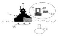
- FIG. 4is a schematic representation of an exemplary system.
- the present inventionscomprise a method of providing bounds for approximations for tracking an object such as target 2 with respect to a first object such as ownship 1 .
- the present inventionscomprise methods for creating calculations useful for bounding tracking sensor localization using a substantially minimum amount of data, in a preferred embodiment especially using passively obtained data as that term is understood by those of ordinary skill in the target detection arts.
- the methodscomprise calculating relative bearing at a closet point of approach (“CPA”) and time of CPA independently of other position data, estimating target motion analysis (“TMA”) solution noise, and detecting contact maneuvers.
- the methods of the present inventionsmay be used to conduct passive TMA using symmetries associated with two different views of a problem to be solved, e.g. two reference frames and two points of interest.
- a first of these frames, geographic frame of reference 100is shown in FIG. 1 and second frame of reference, relative frame of reference 200 , is shown in FIG. 2 .
- the “points of interest”include a first physical object such as ownship 1 , and a second, target 2 , such as second vessel.
- ownshipmeans a first reference point that is not a target, i.e. the vessel making the calculations.
- Each of these points of interestmay be in motion or stationary, and, if in motion, may be in motion in different planes with respect to each other.
- Target motion analysisor TMA means that the course and speed for target 2 , which may initially be unknown, are resolved as well as the range to and bearing of target 2 at or for a predetermined time frame with respect to ownship 1 .
- bearing at CPA, time of CPA, a minimum range to the target with associated course and speed for the minimum range only as a limiting condition, and an initial estimate of the target's true range, course and speedmay be determined.
- target 2may be another vessel, an iceberg, a submerged object such as a ledge or reef, or the like, assuming that target 2 emits a signal that can be detected by a passive sensor for the passive solution.
- the methods of the present inventionsmay be used with partially or fully submerged features such as rocks or debris, floating materials, stationary materials, and the like, or combinations thereof, especially if the presence of such features may be determined, but a measurement of range to the feature may be lacking in the detection device that detects the feature.
- active as well as passive datamay be used in the present inventions' methods, in which case any single active signal may be used to determine a range value which can then be used in conjunction with passive data to fully resolve range, bearing, course and speed.
- the present inventions' methodscomprise obtaining at least three bearing and time data points for a first estimate, e.g. at time points t 1 , t 2 , t 3 , t 4 . These data are used to isolate a passive TMA estimate based on a single leg of time tagged, bearings only data, i.e. no maneuvering of the first point of interest such as ownship 1 is required to obtain a passive estimate. Further, the present inventions' methods comprise a closed form expression for an estimate that may be resolved in a single iteration as opposed to prior art methods such as those using first order statistical solutions.
- the present inventions' methodsutilize velocity vectors of the two items of interest, i.e. vector 13 and estimated vector 30 . These velocity vectors, when arranged to determine their vector difference, form one side 52 , 53 of a parallelogram as well as a diagonal of that parallelogram, shown as darkened portion 51 of vector 13 .
- the perpendicular distances to respective opposite sides of the parallelogramchange in a predetermined fashion, i.e.
- the corresponding length of the diagonalmust increase by an amount equal to the relative velocity of ownship 1 and target 2 multiplied by the new elapsed time value for the second course crossing minus t 0 , such that perpendicular distance to opposing sides increases by an amount proportional to twice the range at CPA. Additionally, the greater the difference between values of adjacent vertices, the smaller the perpendicular distance to opposing sides.
- successive time-lagged bearing linese.g. lines 11 and 12
- solution parabola 15in geometric reference frame 100 for substantially all geometries involving two points of interest 1 , 2 , where each of the points of interest 1 , 2 maintains a substantially constant respective course and speed over a time period used for obtaining bearing measurements.
- Solution parabola 15is formed by recognizing that each of the bearing lines 11 , 12 , 13 , 20 , 30 in geographic reference frame 100 are tangent to solution parabola 15 at a predetermined, unique point.
- solution parabola 15will be fixed in geographic reference frame 100 , and each data set to be gathered will generate one and one only solution parabola 15 , although different data sets may generate the same solution parabola 15 .
- the value of the bearing at the CPA, e.g. angle 50 ′is constant for potential ranges at CPA.
- the difference vector of each potential velocity vector pairi.e.
- velocity vector for target 2 and velocity vector of ownship 1remains parallel for all geometries involving those two points of interest where each point of interest 1 , 2 maintains its respective course and speed at a constant value during the time of measurements and calculation.
- Thisallows calculation of bearing at CPA, time of CPA, and minimum range at CPA, with data comprising a single leg of passive, time tagged bearings. Further, this allows estimates of TMA solutions based on minimum range and preferred range estimates with data comprising a single leg of passive, time tagged bearings.
- the presently preferred embodiment of the present inventions' methodsrequires fixing an ownship 1 at rest reference frame 200 with respect to geographic reference frame 100 .
- thismay be accomplished by requiring that the location of ownship 1 at an initial time t 0 is the same point in the two reference frames, e.g. 10 , and that the bearing value BRG 0 is equal to zero (as used herein “BRG” means bearing).
- an additional stepmay be required to reflect the original bearing line data, e.g. 13 , around a preferred bearing line in the original data set indicated by the axis of original solution parabola 15 to generate revised parabola 15 for a set of pseudo-data that reflects the course of target 2 in a reference frame for which the incident angles of courses is less than ⁇ /2.
- This situationwill also require extrapolating the course of ownship 1 into a predetermined future time point and reversing the course such that the ownship arrives at the same point at the time ownship 1 crosses the course of target 2 .
- ownship 1is located initially at point 10 .
- a first step to calculation of solution parabola 15is to obtain three bearing data points, e.g. at times t 1 ,t 2 ,t 3 ,or t 4 , wherein the times t 1 ,t 2 ,t 3 , or t 4 at which the bearing data points were obtained are also obtained.
- Bearing datais collected in a fixed ownship reference frame such as frame 100 . At a minimum, three bearing-time data points are obtained that are relative bearings with respect to point 10 .
- Bearing datamay then be translated to a moving ownship reference frame 200 .
- Two sets of datamay form vectors, one set representing target 2 , e.g. 30 , and the other set representing ownship 1 , e.g. 13 , which may then cross each other at different times.
- vectors 30 and 13may cross when target 2 appears at 0° relative bearing or 180° known bearing, or when ownship 1 appears at 0° relative to the course of target 2 or when ownship 1 appears at 180° unknown to the course of target 2 .
- bearing line 20selects at least one potential solution point, e.g. bearing line 20 , to indicate a range at CPA.
- bearing line 20may be selected manually by examining target geometry.
- bearing line 20may be selected automatically such as by using artificial intelligence methods, heuristics, or the like, or a combination thereof.
- ⁇ i0 (2)
- the formulae of the present inventions' methodsmay then be used to calculate a bearing fan to determine bearing data at a predetermined time in the future, independent of other position data.
- a bearing fanis a group of bearing data spaced at predetermined points in time that predicts where in bearing space target 2 will be at some point in future time, assuming that target 2 and ownship 1 maintain their current course and speed.
- the present inventionsmay be used to generate both relative and true bearings and time at CPA, where the time at relative bearing equals zero degrees (0°) or one hundred eighty degrees (180°).
- the formulaealso provide an early estimate of minimum target ranges for any bearing, independent of other position data. Further, the formulae may be useful in many other ways, by way of example and not limitation for providing parameters useful for early target maneuver detectors or Open/Close determinations as well as estimates of a ratio of relative speed to range at CPA.
- the present inventions' methodsmay further be used to provide a real-time measure of the effect of noise on potential solutions.
- this real-time measurebegins with a fourth data point, e.g. data point t 4 .
- the direction of the relative velocity vector 60can be determined.
- Computer 200may comprise any suitable computer known in the art.
- Computer 200further comprises a processor, memory, and output device (not shown in the figures) as well as range calculation software executing within computer 200 .
- Output device 210may comprise a display device 210 , a hard copy device 212 , or the like, or a combination thereof.
- Data sets comprising passive bearing datamay be gathered such as by using one or more sensors (shown as 230 in FIG. 4 for illustration) deployed within or near ownship 1 and capable of passively obtaining a bearing to target 2 from a desired location such as ownship 1 and providing measurements related to target 2 and ownship 1 .
- Sensors 230may comprise any suitable sensors known in the art such as passive acoustic sensors.
- the datamay be passively obtained by numerous means as will be familiar to those of ordinary skill in the passive data acquisition arts. Once gathered, these data may be stored for later processing in the memory of computer 200 or in a passive bearing data collection device (not shown in the figures) that is addressably in communication with the computer. The analysis performed may occur within the computer or a portion of the computer which has been programmed to analyze the data received by the sensors.
- the computermay retrieve at least three of the stored bearing data points obtained from the bearing detector, such as from the computer's memory.
- the range calculation softwaremay then use the three retrieved bearing data points to determine a speed contribution V os cos( ⁇ ⁇ ) of a first point of interest to a distance from a relative velocity vector over a time from t 0 to t 0 ′ in accordance with the teachings of the present inventions.
- 0 ;
- the range calculation softwaremay then generate a representation of the probability of the location of target 1 and present that information such as on the output device.
- relative velocity vector 60is perpendicular to the relative bearing line 20 at CPA in fixed ownship reference frame 100 , allowing for calculation of a minimum range estimate at CPA R CPA that is substantially independent of actual contact range.
- a minimum range estimate calculationis possible because a point when CPA occurs is known as is the point at which target 2 is detected at relative bearing equals ⁇ ⁇ .
- V REL R CPA[ tan ⁇ ( ⁇ ⁇ ) - tan ⁇ ( ⁇ i ) 1 + tan ⁇ ( ⁇ ⁇ ) ⁇ tan ⁇ ( ⁇ i ) - tan ⁇ ( ⁇ ⁇ ) - tan ⁇ ( ⁇ j ) 1 + tan ⁇ ( ⁇ ⁇ ) ⁇ tan ⁇ ( ⁇ j ) ] ⁇ ⁇ ⁇ t ij ( 8 )
- equation (8)
- MinR CPAV os (t ⁇ ⁇ t i )cos( ⁇ ⁇ ⁇ i ) ⁇ i
- 0 (10)
- ⁇ jcurrent bearing measure (11) where the terms in equation (11) are defined above.
- R (CURRENTMINIMUM)R CPA(MINIMUM) /cos( ⁇ 0 ⁇ i ) (14)
- the abovemay be used to base target open-close on measurements calculated at the time of the decision.
- a Cartesian graph of target maneuvers and noiseif more than three points are used, a series of subsequent measurements may be used to determine maneuvering of target 2 .
- a set of five or more usable bearing pointsmay be obtained as a set of calculated points C 1 , C 2 , and C 3 in accordance with the teachings of the present inventions during times ⁇ t 1 ,t 2 ,t 3 ⁇ , ⁇ t 2 ,t 3 ,t 4 ⁇ , and ⁇ t 3 ,t 4 ,t 5 ⁇ (these time points are not shown in FIG. 3 ).
- Points C 1 , C 2 , and C 3may be extrapolated to indicate that target 2 (shown as the dark circles in FIG. 3 ) is maneuvering in a non-linear fashion.
- the estimatesmay be used to determine noise or a range of noise in the readings.
- a set of five or more usable bearing pointsmay be interpreted as a set of calculated points P 1 , P 2 , and P 3 obtained in accordance with the teachings of the present inventions during times ⁇ t 6 ,t 7 ,t 8 ⁇ , ⁇ t 7 ,t 8 ,t 9 ⁇ , and ⁇ t 8 ,t 9 ,t 10 ⁇ (these time points are not shown in FIG. 3 ).
- P 2can be seen to have deviated from a predicted point P 2 ′, indicating that noise is present in the system.
- trends over timemay therefore use these deviations to estimate the amount and effects of noise present in the system.
- analysis of deviation from a predicted pointmay be made with four points.
- a fifth pointmay then be obtained and used to determine if the deviation is random or the result of a deterministic event, e.g. a maneuvering of target 2 .
- a minimum set of points required to detect the possible presence of noiseis four, and the minimum set of points required to detect the possible presence of maneuvering of target 2 is five.
- a fourth data pointmay be obtained.
- the fourth data pointshould yield the same solution, i.e., the angle to bearing at CPA relative to the heading of ownship 1 , and the time of CPA will be constant for all combinations of the three of four bearing data points.
- a deviation in the bearing at CPA relative to the heading of ownship 1 and the time of CPArepresents noise in the system which can be detected by this method of calculating the angle to bearing at CPA for each potential solution.
- Prior art methodslook at each bearing measurement as a unique point in “the” solution set and do not consider triplet-wise combinations of points as potential solutions to the angle at CPA, each one as valid as the other, if the bearing measurements are independent. Therefore, with the present inventions, with four data points, four potential solutions may be investigated; with five independent points, ten potential solutions may be investigated; and with six independent points, twenty potential solutions may be investigated. This is quickly recognized as the number of possible combinations of n items taken three at a time. A statistical analysis of the potential solutions may then yield trends and/or the mean and standard deviation of bearings at CPA. The mean of the bearing at CPA and the mean time of CPA are more accurate solutions of the bearing at CPA and time of CPA than any one potential solution based on a triplet of bearing measurements.
- the present inventionsmay allow creating twenty solutions with only six data points rather than waiting for twenty data points. Likewise, four points may be sufficient to determine that there is noise in system and calculating four bearing angle solutions at CPA provides a first order estimate of the magnitude of the noise and a first order estimate of the mean bearing at CPA and mean time of CPA.
- bearing rate curve inflection pointsare always plus or minus around 30° of the BRG at CPA.
Landscapes
- Physics & Mathematics (AREA)
- Engineering & Computer Science (AREA)
- General Physics & Mathematics (AREA)
- Radar, Positioning & Navigation (AREA)
- Remote Sensing (AREA)
- Measurement Of Velocity Or Position Using Acoustic Or Ultrasonic Waves (AREA)
- Radar Systems Or Details Thereof (AREA)
Abstract
Description
tan(θβ−θi)/=VREL(tβ−ti)/RCPA|θi=0 (1)
tβ=RCPA[tan(θβ−θi)/VREL]+ti|θi=0 (2)
In these equations (1), (2), and (3),
- θβis as defined in equation (3) and representatively shown as
angle 50 inFIG. 1 ; - θiis the bearing angle to the
target 2 relative toownship 1 at time tiand representatively shown asangle 50′ inFIG. 1 ; - tβis the time at which θβwas measured;
- tiis the time at which θiwas measured;
- Δt is the difference between two time measurements, e.g. Δtj,kis the difference between time tjand time tk;
- VRELis the difference velocity between
target 2 andownship 1; and - RCPAis the range to target2 at CPA.
- θβis as defined in equation (3) and representatively shown as
Min RCPA=Vos(tβ−ti)cos(θβ−θi)θ
tan(θi−θ0)=(ti−t0)(VR/RCPA) (4)
As used in equation (4),
- θ0is the angle between
ownship 1's heading andtarget 2 at an initial time t0; - θiis the angle between
ownship 1's heading andtarget 2 at time ti; - tiis the time of bearing reading θi; and
- t0is the time of bearing reading θ0.
Further, the ratio VR/RCPAis a calculated value, and therefore VRmay be estimated based on an estimated value of RCPA. Alternatively, RCPAmay be estimated based on an estimated value of VR.
- θ0is the angle between
Min RCPA=Vos(tβ−t0)cos(θβ−θ0) (5)
In equation (5),
- tβis the time at which θβwas measured;
- t0is the time of bearing reading θ0;
- Vosis magnitude of the velocity of ownship; and
- θ0is the angle between
ownship 1′s heading andtarget 2 at a time ti=0.
RCPA
where
- ΔtCCis the difference between course crossings, course crossings being defined as the time when
ownship 1 crosses thetarget 2's course and to and the other components have the definitions given above.
- ΔtCCis the difference between course crossings, course crossings being defined as the time when
In equation (7),
- θiis the angle between
ownship 1's heading andtarget 2 at time ti; - θjis the angle between
ownship 1's heading andtarget 2 at time tj; - θkis the angle between
ownship 1′s heading andtarget 2 at time tk; and - Δtα,βis the time difference between measurements θα, θβrespectively, i.e., where α and β are generic indices which are respectively pair-wise, i.e. (j,k), (k,i), and (i,j).
- θiis the angle between
In equation (8),
- θβis the BRG at CPA;
- θiis the angle between
ownship 1's heading andtarget 2 at time ti; - θjis the angle between
ownship 1's heading andtarget 2 at time tj; and - Δti,jis the time difference between measurements θiand θj.
In equation (9),
- θβis the angle between
ownship 1's heading andtarget 2 at CPA; - θiis the angle between
ownship 1's heading andtarget 2 at time ti; - tiis the time of bearing reading θi; and
- tβis the time of bearing reading θβ, time at which CPA occurs.
- θβis the angle between
MinRCPA=Vos(tβ−ti)cos(θβ−θi)θ
In equation (10),
- θβis the angle between
ownship 1's heading andtarget 2 at CPA; - θiis the angle between
ownship 1's heading andtarget 2 at time ti; - Vosis a magnitude of ownship's velocity;
- tiis time of bearing reading θi; and
- tβis the is the time at which θβwas measured.
- θβis the angle between
Min Rest=Min. RCPA/cos(θβ−θj)|θj=current bearing measure (11)
where the terms in equation (11) are defined above.
R(CURRENTMINIMUM)=RCPA(MINIMUM)/cos(θ0−θi) (14)
Claims (83)
Min RCPA=VOS(tβ−ti)cos(θβ−θi)θ
Min RCPA=Vos(tβ−ti)cos(θβ−θi)θ
Priority Applications (1)
| Application Number | Priority Date | Filing Date | Title |
|---|---|---|---|
| US11/318,398USRE42546E1 (en) | 2002-03-27 | 2005-12-22 | Method and system for target localization |
Applications Claiming Priority (2)
| Application Number | Priority Date | Filing Date | Title |
|---|---|---|---|
| US10/108,236US6668218B1 (en) | 2002-03-27 | 2002-03-27 | Method and system for target localization |
| US11/318,398USRE42546E1 (en) | 2002-03-27 | 2005-12-22 | Method and system for target localization |
Related Parent Applications (1)
| Application Number | Title | Priority Date | Filing Date |
|---|---|---|---|
| US10/108,236ReissueUS6668218B1 (en) | 2002-03-27 | 2002-03-27 | Method and system for target localization |
Publications (1)
| Publication Number | Publication Date |
|---|---|
| USRE42546E1true USRE42546E1 (en) | 2011-07-12 |
Family
ID=29731676
Family Applications (2)
| Application Number | Title | Priority Date | Filing Date |
|---|---|---|---|
| US10/108,236CeasedUS6668218B1 (en) | 2002-03-27 | 2002-03-27 | Method and system for target localization |
| US11/318,398Expired - LifetimeUSRE42546E1 (en) | 2002-03-27 | 2005-12-22 | Method and system for target localization |
Family Applications Before (1)
| Application Number | Title | Priority Date | Filing Date |
|---|---|---|---|
| US10/108,236CeasedUS6668218B1 (en) | 2002-03-27 | 2002-03-27 | Method and system for target localization |
Country Status (1)
| Country | Link |
|---|---|
| US (2) | US6668218B1 (en) |
Cited By (2)
| Publication number | Priority date | Publication date | Assignee | Title |
|---|---|---|---|---|
| US20110310703A1 (en)* | 2010-06-19 | 2011-12-22 | Atlas Elektronik Gmbh | Method and apparatus for passive determination of target data |
| US20140140177A1 (en)* | 2012-01-06 | 2014-05-22 | Agency For Defense Development | User-interface target motion analysis method using two-dimensional parameter control and speed zoom |
Families Citing this family (13)
| Publication number | Priority date | Publication date | Assignee | Title |
|---|---|---|---|---|
| US6668218B1 (en)* | 2002-03-27 | 2003-12-23 | Lockheed Martin Corporation | Method and system for target localization |
| US7451059B2 (en) | 2003-03-02 | 2008-11-11 | Tomer Malchi | True azimuth and north finding method and system |
| IL154701A0 (en)* | 2003-03-02 | 2004-05-12 | Yaniv Malchi | Passive target acquisition system and a true north locating system |
| US20060058954A1 (en)* | 2003-10-08 | 2006-03-16 | Haney Philip J | Constrained tracking of ground objects using regional measurements |
| US7259693B2 (en)* | 2004-04-14 | 2007-08-21 | Miller Russell E | Air vessel tracking system and method |
| US7769502B2 (en)* | 2005-05-26 | 2010-08-03 | Lockheed Martin Corporation | Survivability/attack planning system |
| GB2445384A (en)* | 2006-10-12 | 2008-07-09 | Nokia Corp | Determining the position of a signal source |
| DE102007019444B3 (en)* | 2007-04-25 | 2008-04-10 | Atlas Elektronik Gmbh | Passive determination of target data by selective reception of acoustic waves used in e.g. carrier vehicle, involves using electroacoustic transducer arrangement for sonar reception on carrier vehicle to determine position of target |
| US7577544B2 (en)* | 2007-06-26 | 2009-08-18 | Ge Homeland Protection, Inc. | Method and system for improving target localization and characterization |
| US8270255B2 (en)* | 2008-05-30 | 2012-09-18 | Lockheed Martin Corporation | System for measuring acoustic signature of an object in water |
| DE102008030053B4 (en)* | 2008-06-25 | 2010-03-18 | Atlas Elektronik Gmbh | Method and apparatus for passively determining target parameters |
| US20100030520A1 (en)* | 2008-07-31 | 2010-02-04 | Collier Jarrell D | System for Real-Time Object Detection and Interception |
| GB0900390D0 (en)* | 2009-01-12 | 2009-02-11 | Sonardyne Internat Ltd | Subsea measurement system and method of determining a subsea location-related parameter |
Citations (30)
| Publication number | Priority date | Publication date | Assignee | Title |
|---|---|---|---|---|
| US4148029A (en) | 1976-10-13 | 1979-04-03 | Westinghouse Electric Corp. | System for estimating acceleration of maneuvering targets |
| US5067096A (en) | 1990-09-14 | 1991-11-19 | Honeywell Inc. | Target engagement system for determining proximity to a target |
| US5095467A (en) | 1990-09-14 | 1992-03-10 | Alliant Techsystems Inc. | Target tracking system for determining bearing of a target |
| US5248978A (en) | 1991-08-16 | 1993-09-28 | Kaman Aerospace Corporation | Underwater guide vehicle for removal of submerged and floating navigational hazards |
| US5479360A (en) | 1992-12-21 | 1995-12-26 | Martin Marietta Corporation | Target passive ranging without an ownship maneuver |
| US5537368A (en) | 1993-09-22 | 1996-07-16 | The United States Of America As Represented By The Secretary Of The Navy | Enhanced adaptive statistical filter providing improved performance for target motion analysis noise discrimination |
| US5631653A (en) | 1996-04-25 | 1997-05-20 | Hughes Electronics | Dynamic inertial coordinate system maneuver detector and processing method |
| US5675720A (en) | 1993-09-14 | 1997-10-07 | Fujitsu Limited | Method of searching for points of closest approach, and preprocessing method therefor |
| US5732043A (en) | 1990-06-12 | 1998-03-24 | Hughes Aircraft Company Now Known As Hughes Electronics | Optimized deterministic bearings only target motion analysis technique |
| US5867256A (en) | 1997-07-16 | 1999-02-02 | Raytheon Ti Systems, Inc. | Passive range estimation using image size measurements |
| US5933099A (en) | 1997-02-19 | 1999-08-03 | Mahon; James | Collision avoidance system |
| US5999117A (en) | 1998-06-16 | 1999-12-07 | Northrop Grumman Corporation | Method for tracking and detecting turns of maneuvering targets |
| US6016453A (en) | 1997-04-21 | 2000-01-18 | The United States Of America As Represented By The Secretary Of The Navy | Method for the collection and replay of submarine operational data |
| US6093923A (en) | 1996-09-11 | 2000-07-25 | Golf Age Technologies, Inc. | Golf driving range distancing apparatus and methods |
| US6115700A (en) | 1997-01-31 | 2000-09-05 | The United States Of America As Represented By The Secretary Of The Navy | System and method for tracking vehicles using random search algorithms |
| US6125308A (en)* | 1997-06-11 | 2000-09-26 | The United States Of America As Represented By The Secretary Of The Army | Method of passive determination of projectile miss distance |
| US6133867A (en) | 1998-01-02 | 2000-10-17 | Eberwine; David Brent | Integrated air traffic management and collision avoidance system |
| US6198693B1 (en) | 1998-04-13 | 2001-03-06 | Andrea Electronics Corporation | System and method for finding the direction of a wave source using an array of sensors |
| US6199471B1 (en) | 1999-05-21 | 2001-03-13 | The United States Of America As Represented By The Secretary Of The Navy | Method and system for determining the probable location of a contact |
| US6215898B1 (en) | 1997-04-15 | 2001-04-10 | Interval Research Corporation | Data processing system and method |
| US6231002B1 (en) | 1990-03-12 | 2001-05-15 | The Boeing Company | System and method for defending a vehicle |
| US6231003B1 (en) | 1990-03-12 | 2001-05-15 | The Boeing Company | Apparatus for defending a vehicle against an approaching threat |
| US6249241B1 (en) | 1995-09-21 | 2001-06-19 | The United States Of America As Represented By The Secretary Of The Navy | Marine vessel traffic system |
| US6259974B1 (en)* | 2000-03-27 | 2001-07-10 | The United States Of America As Represented By The Secretary Of The Navy | Automated ballistic constant determination |
| US6260759B1 (en) | 1998-08-11 | 2001-07-17 | Northrop Grumman Corporation | Method for tracking a target having substantially constrained movement |
| US6275773B1 (en) | 1993-08-11 | 2001-08-14 | Jerome H. Lemelson | GPS vehicle collision avoidance warning and control system and method |
| US20030093187A1 (en)* | 2001-10-01 | 2003-05-15 | Kline & Walker, Llc | PFN/TRAC systemTM FAA upgrades for accountable remote and robotics control to stop the unauthorized use of aircraft and to improve equipment management and public safety in transportation |
| US6573486B1 (en)* | 2002-02-22 | 2003-06-03 | Northrop Grumman Corporation | Projectile guidance with accelerometers and a GPS receiver |
| US6665631B2 (en)* | 2001-09-27 | 2003-12-16 | The United States Of America As Represented By The Secretary Of The Navy | System and method for measuring short distances |
| US6668218B1 (en)* | 2002-03-27 | 2003-12-23 | Lockheed Martin Corporation | Method and system for target localization |
- 2002
- 2002-03-27USUS10/108,236patent/US6668218B1/ennot_activeCeased
- 2005
- 2005-12-22USUS11/318,398patent/USRE42546E1/ennot_activeExpired - Lifetime
Patent Citations (32)
| Publication number | Priority date | Publication date | Assignee | Title |
|---|---|---|---|---|
| US4148029A (en) | 1976-10-13 | 1979-04-03 | Westinghouse Electric Corp. | System for estimating acceleration of maneuvering targets |
| US6231003B1 (en) | 1990-03-12 | 2001-05-15 | The Boeing Company | Apparatus for defending a vehicle against an approaching threat |
| US6231002B1 (en) | 1990-03-12 | 2001-05-15 | The Boeing Company | System and method for defending a vehicle |
| US5732043A (en) | 1990-06-12 | 1998-03-24 | Hughes Aircraft Company Now Known As Hughes Electronics | Optimized deterministic bearings only target motion analysis technique |
| US5067096A (en) | 1990-09-14 | 1991-11-19 | Honeywell Inc. | Target engagement system for determining proximity to a target |
| US5095467A (en) | 1990-09-14 | 1992-03-10 | Alliant Techsystems Inc. | Target tracking system for determining bearing of a target |
| US5248978A (en) | 1991-08-16 | 1993-09-28 | Kaman Aerospace Corporation | Underwater guide vehicle for removal of submerged and floating navigational hazards |
| US5479360A (en) | 1992-12-21 | 1995-12-26 | Martin Marietta Corporation | Target passive ranging without an ownship maneuver |
| US6487500B2 (en) | 1993-08-11 | 2002-11-26 | Jerome H. Lemelson | GPS vehicle collision avoidance warning and control system and method |
| US6275773B1 (en) | 1993-08-11 | 2001-08-14 | Jerome H. Lemelson | GPS vehicle collision avoidance warning and control system and method |
| US5675720A (en) | 1993-09-14 | 1997-10-07 | Fujitsu Limited | Method of searching for points of closest approach, and preprocessing method therefor |
| US5537368A (en) | 1993-09-22 | 1996-07-16 | The United States Of America As Represented By The Secretary Of The Navy | Enhanced adaptive statistical filter providing improved performance for target motion analysis noise discrimination |
| US6249241B1 (en) | 1995-09-21 | 2001-06-19 | The United States Of America As Represented By The Secretary Of The Navy | Marine vessel traffic system |
| US5631653A (en) | 1996-04-25 | 1997-05-20 | Hughes Electronics | Dynamic inertial coordinate system maneuver detector and processing method |
| US6093923A (en) | 1996-09-11 | 2000-07-25 | Golf Age Technologies, Inc. | Golf driving range distancing apparatus and methods |
| US6115700A (en) | 1997-01-31 | 2000-09-05 | The United States Of America As Represented By The Secretary Of The Navy | System and method for tracking vehicles using random search algorithms |
| US5933099A (en) | 1997-02-19 | 1999-08-03 | Mahon; James | Collision avoidance system |
| US6215898B1 (en) | 1997-04-15 | 2001-04-10 | Interval Research Corporation | Data processing system and method |
| US6016453A (en) | 1997-04-21 | 2000-01-18 | The United States Of America As Represented By The Secretary Of The Navy | Method for the collection and replay of submarine operational data |
| US6125308A (en)* | 1997-06-11 | 2000-09-26 | The United States Of America As Represented By The Secretary Of The Army | Method of passive determination of projectile miss distance |
| US5867256A (en) | 1997-07-16 | 1999-02-02 | Raytheon Ti Systems, Inc. | Passive range estimation using image size measurements |
| US6133867A (en) | 1998-01-02 | 2000-10-17 | Eberwine; David Brent | Integrated air traffic management and collision avoidance system |
| US6198693B1 (en) | 1998-04-13 | 2001-03-06 | Andrea Electronics Corporation | System and method for finding the direction of a wave source using an array of sensors |
| US5999117A (en) | 1998-06-16 | 1999-12-07 | Northrop Grumman Corporation | Method for tracking and detecting turns of maneuvering targets |
| US6260759B1 (en) | 1998-08-11 | 2001-07-17 | Northrop Grumman Corporation | Method for tracking a target having substantially constrained movement |
| US6199471B1 (en) | 1999-05-21 | 2001-03-13 | The United States Of America As Represented By The Secretary Of The Navy | Method and system for determining the probable location of a contact |
| US6259974B1 (en)* | 2000-03-27 | 2001-07-10 | The United States Of America As Represented By The Secretary Of The Navy | Automated ballistic constant determination |
| US6665631B2 (en)* | 2001-09-27 | 2003-12-16 | The United States Of America As Represented By The Secretary Of The Navy | System and method for measuring short distances |
| US20030093187A1 (en)* | 2001-10-01 | 2003-05-15 | Kline & Walker, Llc | PFN/TRAC systemTM FAA upgrades for accountable remote and robotics control to stop the unauthorized use of aircraft and to improve equipment management and public safety in transportation |
| US6965816B2 (en) | 2001-10-01 | 2005-11-15 | Kline & Walker, Llc | PFN/TRAC system FAA upgrades for accountable remote and robotics control to stop the unauthorized use of aircraft and to improve equipment management and public safety in transportation |
| US6573486B1 (en)* | 2002-02-22 | 2003-06-03 | Northrop Grumman Corporation | Projectile guidance with accelerometers and a GPS receiver |
| US6668218B1 (en)* | 2002-03-27 | 2003-12-23 | Lockheed Martin Corporation | Method and system for target localization |
Non-Patent Citations (5)
| Title |
|---|
| Albus, J.S.; "4-D/RCS, A reference model architecture for demo III;" 1997; Internet; http://www.isd.mel.nist.gov/documents/library/isd-pub.html; pp. 1-95. |
| Price et al., Discarding armture and barrel optimiztion or a cannon caliber electomagnetic laucher system, 1994, IEEE, p. 225230.* |
| Shukla et al., A powerfulkinematic model for proportionalnavigation of guided weapons against maneuvering targets, 1989, IEEE, p. 194-208.* |
| Wei et al., Estimation of vector miss distnace based on source localization, 2004, IEEE, p. 604-609.* |
| Zielinski et al., Integrated launch package performance in the cannon-caliber launcher, 1997, IEEE, p. 163-168.* |
Cited By (4)
| Publication number | Priority date | Publication date | Assignee | Title |
|---|---|---|---|---|
| US20110310703A1 (en)* | 2010-06-19 | 2011-12-22 | Atlas Elektronik Gmbh | Method and apparatus for passive determination of target data |
| US8804459B2 (en)* | 2010-06-19 | 2014-08-12 | Atlas Elektronik Gmbh | Method and apparatus for passive determination of target data |
| US20140140177A1 (en)* | 2012-01-06 | 2014-05-22 | Agency For Defense Development | User-interface target motion analysis method using two-dimensional parameter control and speed zoom |
| US8958268B2 (en)* | 2012-01-06 | 2015-02-17 | Agency For Defense Development | User-interface target motion analysis method using two-dimensional parameter control and speed zoom |
Also Published As
| Publication number | Publication date |
|---|---|
| US6668218B1 (en) | 2003-12-23 |
Similar Documents
| Publication | Publication Date | Title |
|---|---|---|
| USRE42546E1 (en) | Method and system for target localization | |
| Hong et al. | Radarslam: Radar based large-scale slam in all weathers | |
| EP1610152B1 (en) | Tracking of a moving object for a self-defence system | |
| US8265817B2 (en) | Inertial measurement with an imaging sensor and a digitized map | |
| Adams et al. | Robotic navigation and mapping with radar | |
| JP2996956B1 (en) | Rocket trajectory estimation method using tracking device, rocket future position prediction method, rocket identification method, rocket situation detection method | |
| US8106814B2 (en) | Method of estimating the elevation of a ballistic projectile | |
| KR101882483B1 (en) | Apparatus and method for detecting obstacle by unmanned surface vessel | |
| JPH1031067A (en) | Radar target tracking system in background clutter | |
| Pillon et al. | Observability: range-only vs. bearings-only target motion analysis for a leg-by-leg observer's trajectory | |
| Piskur et al. | Algorithms for passive detection of moving vessels in marine environment | |
| US5999117A (en) | Method for tracking and detecting turns of maneuvering targets | |
| Inzartsev et al. | AUV application for inspection of underwater communications | |
| US6184831B1 (en) | Method and system for determining location and velocity of electromagnetic emitters using doppler frequency measurements | |
| Baerveldt et al. | Comparing multiple extended object tracking with point based multi object tracking for lidar in a maritime context | |
| JP5971981B2 (en) | Target motion prediction apparatus and target motion prediction method | |
| EP3779923B1 (en) | Search support for calculating a route for searching an object | |
| EP1405095B1 (en) | Apparatus and method of tracking objects in flight | |
| Michaelis et al. | Generating odometry measurements from automotive radar doppler measurements | |
| KR101837845B1 (en) | System and method for obtaining information of underwater target | |
| JP3629328B2 (en) | Target motion estimation device | |
| JP2001083232A (en) | Passive target positioning device | |
| Kim et al. | Imaging sonar based navigation method for backtracking of AUV | |
| Jauffret et al. | Leg-by-leg Bearings-Only Target Motion Analysis Without Observer Maneuver | |
| SE509699C2 (en) | Ignition device for tanks |
Legal Events
| Date | Code | Title | Description |
|---|---|---|---|
| AS | Assignment | Owner name:TECHNOLOGY, PATENTS AND LICENSING III, LLC, PENNSY Free format text:ASSIGNMENT OF ASSIGNORS INTEREST;ASSIGNOR:LOCKHEED MARTIN CORPORATION;REEL/FRAME:024779/0612 Effective date:20050218 Owner name:NEVADA ASSET LIQUIDATORS, LLC, NEVADA Free format text:ASSIGNMENT OF ASSIGNORS INTEREST;ASSIGNOR:TECHNOLOGY, PATENTS & LICENSING III, LLC;REEL/FRAME:024779/0630 Effective date:20050420 Owner name:LOCKHEED MARTIN CORPORATION, MARYLAND Free format text:ASSIGNMENT OF ASSIGNORS INTEREST;ASSIGNORS:BULOW, JEFFREY ALAN;PETERS, DOUGLAS MARTIN;REEL/FRAME:024779/0582 Effective date:20020613 | |
| CC | Certificate of correction | ||
| FPAY | Fee payment | Year of fee payment:12 | |
| AS | Assignment | Owner name:F. POSZAT HU, L.L.C., DELAWARE Free format text:MERGER;ASSIGNOR:NEVADA ASSET LIQUIDATORS LLC;REEL/FRAME:037583/0667 Effective date:20150812 | |
| AS | Assignment | Owner name:INTELLECTUAL VENTURES ASSETS 191 LLC, DELAWARE Free format text:ASSIGNMENT OF ASSIGNORS INTEREST;ASSIGNOR:F. POSZAT HU, L.L.C.;REEL/FRAME:062666/0463 Effective date:20221222 | |
| AS | Assignment | Owner name:INTELLECTUAL VENTURES ASSETS 186 LLC, DELAWARE Free format text:SECURITY INTEREST;ASSIGNOR:MIND FUSION, LLC;REEL/FRAME:063295/0001 Effective date:20230214 Owner name:INTELLECTUAL VENTURES ASSETS 191 LLC, DELAWARE Free format text:SECURITY INTEREST;ASSIGNOR:MIND FUSION, LLC;REEL/FRAME:063295/0001 Effective date:20230214 | |
| AS | Assignment | Owner name:MIND FUSION, LLC, WASHINGTON Free format text:ASSIGNMENT OF ASSIGNORS INTEREST;ASSIGNOR:INTELLECTUAL VENTURES ASSETS 191 LLC;REEL/FRAME:064270/0685 Effective date:20230214 |