USRE42371E1 - Scroll machine - Google Patents
Scroll machineDownload PDFInfo
- Publication number
- USRE42371E1 USRE42371E1US12/351,536US35153609AUSRE42371EUS RE42371 E1USRE42371 E1US RE42371E1US 35153609 AUS35153609 AUS 35153609AUS RE42371 EUSRE42371 EUS RE42371E
- Authority
- US
- United States
- Prior art keywords
- discharge
- valve
- machine according
- scroll
- scroll machine
- Prior art date
- Legal status (The legal status is an assumption and is not a legal conclusion. Google has not performed a legal analysis and makes no representation as to the accuracy of the status listed.)
- Expired - Lifetime, expires
Links
Images


Classifications
- F—MECHANICAL ENGINEERING; LIGHTING; HEATING; WEAPONS; BLASTING
- F04—POSITIVE - DISPLACEMENT MACHINES FOR LIQUIDS; PUMPS FOR LIQUIDS OR ELASTIC FLUIDS
- F04C—ROTARY-PISTON, OR OSCILLATING-PISTON, POSITIVE-DISPLACEMENT MACHINES FOR LIQUIDS; ROTARY-PISTON, OR OSCILLATING-PISTON, POSITIVE-DISPLACEMENT PUMPS
- F04C18/00—Rotary-piston pumps specially adapted for elastic fluids
- F04C18/02—Rotary-piston pumps specially adapted for elastic fluids of arcuate-engagement type, i.e. with circular translatory movement of co-operating members, each member having the same number of teeth or tooth-equivalents
- F—MECHANICAL ENGINEERING; LIGHTING; HEATING; WEAPONS; BLASTING
- F04—POSITIVE - DISPLACEMENT MACHINES FOR LIQUIDS; PUMPS FOR LIQUIDS OR ELASTIC FLUIDS
- F04C—ROTARY-PISTON, OR OSCILLATING-PISTON, POSITIVE-DISPLACEMENT MACHINES FOR LIQUIDS; ROTARY-PISTON, OR OSCILLATING-PISTON, POSITIVE-DISPLACEMENT PUMPS
- F04C29/00—Component parts, details or accessories of pumps or pumping installations, not provided for in groups F04C18/00 - F04C28/00
- F04C29/12—Arrangements for admission or discharge of the working fluid, e.g. constructional features of the inlet or outlet
- F04C29/124—Arrangements for admission or discharge of the working fluid, e.g. constructional features of the inlet or outlet with inlet and outlet valves specially adapted for rotary or oscillating piston pumps
- F04C29/126—Arrangements for admission or discharge of the working fluid, e.g. constructional features of the inlet or outlet with inlet and outlet valves specially adapted for rotary or oscillating piston pumps of the non-return type
- F04C29/128—Arrangements for admission or discharge of the working fluid, e.g. constructional features of the inlet or outlet with inlet and outlet valves specially adapted for rotary or oscillating piston pumps of the non-return type of the elastic type, e.g. reed valves
- F—MECHANICAL ENGINEERING; LIGHTING; HEATING; WEAPONS; BLASTING
- F04—POSITIVE - DISPLACEMENT MACHINES FOR LIQUIDS; PUMPS FOR LIQUIDS OR ELASTIC FLUIDS
- F04C—ROTARY-PISTON, OR OSCILLATING-PISTON, POSITIVE-DISPLACEMENT MACHINES FOR LIQUIDS; ROTARY-PISTON, OR OSCILLATING-PISTON, POSITIVE-DISPLACEMENT PUMPS
- F04C18/00—Rotary-piston pumps specially adapted for elastic fluids
- F04C18/02—Rotary-piston pumps specially adapted for elastic fluids of arcuate-engagement type, i.e. with circular translatory movement of co-operating members, each member having the same number of teeth or tooth-equivalents
- F04C18/0207—Rotary-piston pumps specially adapted for elastic fluids of arcuate-engagement type, i.e. with circular translatory movement of co-operating members, each member having the same number of teeth or tooth-equivalents both members having co-operating elements in spiral form
- F04C18/0215—Rotary-piston pumps specially adapted for elastic fluids of arcuate-engagement type, i.e. with circular translatory movement of co-operating members, each member having the same number of teeth or tooth-equivalents both members having co-operating elements in spiral form where only one member is moving
- F—MECHANICAL ENGINEERING; LIGHTING; HEATING; WEAPONS; BLASTING
- F04—POSITIVE - DISPLACEMENT MACHINES FOR LIQUIDS; PUMPS FOR LIQUIDS OR ELASTIC FLUIDS
- F04C—ROTARY-PISTON, OR OSCILLATING-PISTON, POSITIVE-DISPLACEMENT MACHINES FOR LIQUIDS; ROTARY-PISTON, OR OSCILLATING-PISTON, POSITIVE-DISPLACEMENT PUMPS
- F04C2270/00—Control; Monitoring or safety arrangements
- F04C2270/58—Valve parameters
- F—MECHANICAL ENGINEERING; LIGHTING; HEATING; WEAPONS; BLASTING
- F04—POSITIVE - DISPLACEMENT MACHINES FOR LIQUIDS; PUMPS FOR LIQUIDS OR ELASTIC FLUIDS
- F04C—ROTARY-PISTON, OR OSCILLATING-PISTON, POSITIVE-DISPLACEMENT MACHINES FOR LIQUIDS; ROTARY-PISTON, OR OSCILLATING-PISTON, POSITIVE-DISPLACEMENT PUMPS
- F04C23/00—Combinations of two or more pumps, each being of rotary-piston or oscillating-piston type, specially adapted for elastic fluids; Pumping installations specially adapted for elastic fluids; Multi-stage pumps specially adapted for elastic fluids
- F04C23/008—Hermetic pumps
Definitions
- the present inventionrelates to rotary compressors. More particularly the present invention relates to a unique retention system for a direct discharge valve system that is utilized in a scroll compressor.
- Scroll machinesare becoming more and more popular for use as compressors in both refrigeration as well as air conditioning and heat pump applications due primarily to their capability for extremely efficient operation.
- these machinesincorporate a pair of intermeshed spiral wraps, one of which is caused to orbit relative to the other so as to define one or more moving chambers that progressively decrease in size as they travel from an outer suction port towards a center discharge port.
- An electric motoris normally provided that operates to drive the orbiting scroll member via a suitable drive shaft.
- recompression volumeis the volume of the discharge chamber and the discharge port of the compressor when the discharge chamber is at its smallest volume. The minimization of this recompression volume will result in a maximizing of the performance of the compressor.
- the discharge pressurein some situations, such as a blocked condenser fan, it is possible for the discharge pressure to increase sufficiently to stall the drive motor and effect a reverse rotation thereof. As the orbiting scroll orbits in the reverse direction, the discharge pressure will decrease to a point where the motor again is able to overcome this pressure head and orbit the scroll member in the forward direction. However, the discharge pressure will again increase to a point where the drive motor is stalled and the cycle is repeated. Such cycling is undesirable in that it is self-perpetuating. The incorporation of a discharge valve can reduce or eliminate these reverse rotation problems.
- a primary object of the present inventionresides in the provision of a very simple and unique retention system for a discharge valve, which is associated with the non-orbiting scroll and which can easily be assembled into a conventional gas compressor of the scroll type without significant modification of the overall compressor design.
- the discharge valveoperates to minimize the recompression volume and at compressor shut down operates to prohibit backflow of the discharge gas through the compressor and thus driving the compressor in the reverse direction. Prohibiting the reverse operation of the compressor eliminates the normal shut down noise and other problems associated with such reverse rotation.
- the retention systemincludes a wave ring retainer that is disposed within a groove in the non-orbiting scroll member. This groove is located adjacent the discharge valve. The wave ring retainer biases the discharge valve against the non-orbiting scroll member, but the wave ring retainer will deflect at a specified pressure to increase the flow area for the discharge gas.
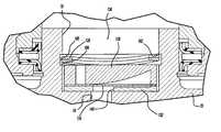
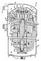
- FIG. 1is a vertical sectional view through the center of a scroll compressor that incorporates a retention system for a discharge valve assembly in accordance with the present invention
- FIG. 2is a top elevational view of the compressor shown in FIG. 1 with the cap and a portion of the partition removed;
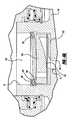
- FIG. 3is an enlarged view of the floating seal assembly and discharge valve assembly illustrated in FIG. 1 ;
- FIG. 4Ais an enlarged view of the discharge valve assembly illustrated in FIGS. 1 and 3 with the discharge valve being biased against the non-orbiting scroll member;
- FIG. 4Bis an enlarged view of the discharge valve assembly illustrated in FIGS. 1 and 3 with the discharge valve being spaced from the non-orbiting scroll member;
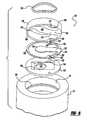
- FIG. 5is an exploded perspective view of the retention system of the discharge valve assembly shown in FIGS. 1 and 3 .
- FIG. 1a scroll compressor that incorporates a retention system for a discharge valving system in accordance with the present invention and which is designated generally by reference numeral 10 .
- Compressor 10comprises a generally cylindrical hermetic shell 12 having welded at the upper end thereof a cap 14 and at the lower end thereof a base 16 having a plurality of mounting feet (not shown) integrally formed therewith.
- Cap 14is provided with a refrigerant discharge fitting 18 .
- a transversely extending partition 22that is welded about its periphery at the same point that cap 14 is welded to shell 12
- a lower bearing housing 24that is suitably secured to shell 12
- a two piece upper bearing housing 26suitably secured to lower bearing housing 24 .
- a drive shaft or crankshaft 28 having an eccentric crank pin 30 at the upper end thereofis rotatably journaled in a bearing 32 in lower bearing housing 24 and a second bearing 34 in upper bearing housing 26 .
- Crankshaft 28has at the lower end a relatively large diameter concentric bore 36 that communicates with a radially outwardly inclined smaller diameter bore 38 extending upwardly therefrom to the top of crankshaft 28 .
- the lower portion of the interior shell 12defines an oil sump 40 that is filled with lubricating oil to a level slightly above the lower end of a rotor 42 , and bore 36 acts as a pump to pump lubricating fluid up crankshaft 28 and into bore 38 and ultimately to all of the various portions of the compressor that require lubrication.
- Crankshaft 28is rotatively driven by an electric motor including a stator 46 , windings 48 passing therethrough and rotor 42 press fitted on crankshaft 28 and having upper and lower counterweights 50 and 52 , respectively.
- the upper surface of upper bearing housing 26is provided with a flat thrust bearing surface 54 on which is disposed an orbiting scroll member 56 having the usual spiral vane or wrap 58 extending upward from an end plate 60 .
- an orbiting scroll member 56having the usual spiral vane or wrap 58 extending upward from an end plate 60 .
- Projecting downwardly from the lower surface of end plate 60 of orbiting scroll member 56is a cylindrical hub having a journal bearing 62 therein and in which is rotatively disposed a drive bushing 64 having an inner bore 66 in which crank pin 30 is drivingly disposed.
- Crank pin 30has a flat on one surface that drivingly engages a flat surface (not shown) formed in a portion of bore 66 to provide a radially compliant driving arrangement, such as shown in Assignee's U.S. Pat. No.
- Oldham coupling 68is also provided positioned between orbiting scroll member 56 and bearing housing 24 and keyed to orbiting scroll member 56 and a non-orbiting scroll member 70 to prevent rotational movement of orbiting scroll member 56 .
- Oldham coupling 68is preferably of the type disclosed in Assignee's co-pending U.S. Pat. No. 5,320,506, the disclosure of which is hereby incorporated herein by reference.
- Non-orbiting scroll member 70is also provided having a wrap 72 extending downwardly from an end plate 74 that is positioned in meshing engagement with wrap 58 of orbiting scroll member 56 .
- Non-orbiting scroll member 70has a centrally disposed discharge passage 76 that communicates with an upwardly open recess 78 which, in turn, is in fluid communication with a discharge muffler chamber 80 defined by cap 14 and partition 22 .
- An annular recess 82is also formed in non-orbiting scroll member 70 within which is disposed a floating seal assembly 84 .
- Recesses 78 and 82 and seal assembly 84cooperate to define axial pressure biasing chambers, which receive pressurized fluid being compressed by wraps 58 and 72 so as to exert an axial biasing force on non-orbiting scroll member 70 to thereby urge the tips of respective wraps 58 , 72 into sealing engagement with the opposed end plate surfaces of end plates 74 and 60 , respectively.
- Seal assembly 84is preferably of the type described in greater detail in U.S. Pat. No. 5,156,539, the disclosure of which is hereby incorporated herein by reference.
- Non-orbiting scroll member 70is designed to be mounted to upper bearing housing 26 in a suitable manner such as disclosed in the aforementioned U.S. Pat. No. 4,877,382 or U.S. Pat. No. 5,102,316, the disclosure of which is hereby incorporated herein by reference.
- floating seal assembly 84is of a coaxial sandwiched construction and comprises an annular base plate 102 having a plurality of equally spaced upstanding integral projections 104 each having an enlarged base portion 106 .
- annular gasket assembly 108Disposed on plate 102 is an annular gasket assembly 108 having a plurality of equally spaced holes that mate with and receive base portions 106 .
- annular spacer plate 110On top of gasket assembly 108 is disposed an annular spacer plate 110 having a plurality of equally spaces spaced holes that also mate with and receive base portions 106 .
- annular gasket assembly 112On top of plate 110 is an annular gasket assembly 112 having a plurality of equally spaced holes that mate with and receive projections 104 .
- seal assembly 84is maintained by an annular upper seal plate 114 , which has a plurality of equally spaced holes mating with and receiving projections 104 .
- Seal plate 114includes a plurality of annular projections 116 , which mate with and extend into the plurality of holes in annular gasket assembly 112 and spacer plate 110 to provide stability to seal assembly 84 .
- Seal plate 114also includes an annular upwardly projecting planar sealing lip 118 . Seal assembly 84 is secured together by swaging the ends of projections 104 as indicated at 120 .
- seal assembly 84therefore provides three distinct seals: first, an inside diameter seal at two interfaces 122 ; second, an outside diameter seal at two interfaces 124 ; and, third, a top seal at 126 .
- Seals 122isolate fluid under intermediate pressure in the bottom of recess 82 from fluid under discharge pressure in recess 78 .
- Seals 124isolate fluid under intermediate pressure in the bottom of recess 82 from fluid under suction pressure within shell 12 .
- Seal 126is between sealing lip 118 and an annular seat portion on partition 22 . Seal 126 isolates fluid at suction pressure from fluid at discharge pressure across the top of seal assembly 84 .
- seal 126The diameter and width of seal 126 are chosen so that the unit pressure between sealing lip 118 and the seat portion on partition 22 is greater than normally encountered discharge pressure, thus ensuring consistent sealing under normal operating conditions of compressor 10 , i.e., at normal operating pressure ratios. Therefore, when undesirable pressure conditions are encountered, seal assembly 84 will be forced downward breaking seal 126 , thereby permitting fluid flow from the discharge pressure zone of compressor 10 to the suction pressure zone of compressor 10 . If this flow is great enough, the resultant loss of flow of motor-cooling suction gas (aggravated by the excessive temperature of the leaking discharge gas) will cause a motor protector to trip thereby the de-energizing motor.
- the width of seal 126is chose so that the unit pressure between sealing lip 118 and the seat portion of partition 22 is greater than normally encountered discharge pressure, thus ensuring consistent sealing.
- the present inventionis directed towards a retention system for a normally open mechanical valve assembly 130 , which is disposed within recess 78 , which is formed in non-orbiting scroll member 70 . While the present invention is being described in conjunction with normally open mechanical valve assembly 130 , the retention system of the present invention can be used with any other type of discharge valve also.
- Valve assembly 130moves between a first or closed condition, a second or open condition, and a third or fully open condition during steady state operation of compressor 10 . Valve assembly 130 will close during the shut down of compressor 10 . When valve assembly 130 is fully closed, the recompression volume is minimized and the reverse flow of discharge gas through scroll members 56 and 70 is prohibited.
- Valve assembly 130is normally open as shown in FIGS. 3 and 4A .
- the normally open configuration for valve assembly 130eliminates the force required to open valve assembly 130 as well as eliminating any mechanical device needed to close valve assembly 130 .
- Valve assembly 130relies on gas pressure differential for closing.
- discharge valve assembly 130is disposed within recess 78 and it comprises a valve seat 132 , a valve plate 134 , a valve stop 136 and a wave ring retainer 138 .
- Valve seat 132is a flat metal disc shaped member defining a discharge passage 140 , a pair of alignment apertures 142 and a cavity 144 .
- Non-orbiting scroll member 70defines a pair of alignment bores. When apertures 142 are in registry with the alignment bores, discharge passage 140 is aligned with discharge passage 76 .
- the shape of discharge passage 140is the same as discharge passage 76 .
- valve seat 132particularly in the area of cavity 144 is minimized to minimize the recompression volume for compressor 10 , which increases the performance of compressor 10 .
- the bottom surface of cavity 144 adjacent to valve plate 134includes a contoured surface 148 .
- the flat horizontal upper surface of valve seat 132is used to secure valve plate 134 around its entire circumference.
- Contoured surface 148 of cavity 144provides for the normally open characteristic of valve assembly 130 .
- Contoured surface 148may be a generally planar surface as shown in FIG. 4A or contoured surface 148 may be a curved surface.
- cavity 144 and contoured surface 148are shown as a pocket within valve seat 132 , it is within the scope of the present invention to have cavity 144 and thus surface 148 extend through the edge of valve seat 132 . Also, it is within the scope of the present invention to eliminate valve seat 132 and incorporate cavity 144 and surface 148 directly into and onto non-orbiting scroll 70 if desired.
- Valve plate 134is a flat thin metal disc shaped member that includes an annular ring 150 , a generally rectangular portion 152 extending radially inward from ring 150 and a generally circular portion 154 attached to the radial inner end of rectangular portion 152 .
- Rectangular portion 152is designed to be smaller in width than circular portion 154 . This reduced section therefore has a lower bending load than circular portion 154 , which results in a faster opening of valve assembly 130 .
- This reduced section of rectangular portion 152is acceptable from a durability standpoint since contoured surface 148 reduces the stress loading on this reduced section.
- the size and shape of portion 154is designed to completely cover discharge passage 140 of valve seat 132 .
- valve plate 134also includes a pair of bosses 156 , which define a pair of alignment apertures 158 . When apertures 158 are in registry with apertures 142 of valve seat 132 , rectangular portion 152 positions circular portion 154 in alignment with discharge passage 140 . The thickness of valve plate 134 is determined by the stresses developed in rectangular portion 152 as valve plate 134 deflects from its closed position to its open position as described below.
- Valve stop 136is a thick metal, disc shaped member that provides support and backing for valve plate 134 and valve seat 132 .
- Valve stop 136is similar in configuration to valve plate 134 and includes an annular ring 160 , a generally rectangular portion 162 extending radially inward from ring 160 , a generally circular portion 164 attached to the radially inner end of rectangular portion 162 and a support section 166 extending between circular portion 164 and ring 160 on the side of portion 164 opposite to portion 162 .
- Valve stop 136also includes a pair of bosses 168 , which define a pair of alignment apertures 170 .
- rectangular portion 162is aligned with rectangular portion 152 of valve plate 134 and it positions circular portion 164 in alignment with circular portion 154 of valve plate 134 .
- Rectangular portion 162 and circular portion 164cooperate to define a curved contoured surface 172 .
- Discharge valve assembly 130is assembled to non-orbiting scroll member 70 by first placing valve seat 132 within recess 78 with contoured surface 148 facing upward while aligning apertures 142 with bores in recess 78 of non-orbitinci non-orbiting scroll member 70 which aligns passage 140 with passage 76 .
- valve plate 134is placed on top of valve plate 132 within recess 78 while aligning apertures 158 with apertures 142 , which aligns circular portion 154 with passage 140 .
- valve step 136is placed on top of valve plate 134 within recess 78 while aligning apertures 170 within apertures 158 , which aligns portions 162 and 164 with portions 152 and 154 , respectively.
- a roll pinis inserted through each aligned set of apertures 170 , 158 and 142 and press fit into each bore of non-orbitinci non-orbiting scroll member 70 to maintain the alignment of these components.
- retainer 138is installed within recess 78 to maintain the assembly of valve assembly 130 with non-orbiting scroll member 70 .
- the assembly of retainer 138sandwiches the entire annular ring 150 of valve seat 132 between the upper flat surface of valve seat 132 and ring 160 of valve stop 136 to secure and retain valve plate 134 .
- Retainer 138is a wave ring retainer that is disposed within a groove 180 formed into recess 78 of non-orbiting scroll member 70 .
- the wave shape of retainer 138causes it to engage both the upper surface 182 and the lower surface 184 of groove 180 to adequately retain discharge valve assembly within recess 78 , as shown in FIG. 4A .
- the wave shape of retainer 138also allows for axial movement of discharge valve assembly due to the resilience and, thus, compression of the wave ring retainer as shown in FIG. 4B .
- Discharge valve assembly 130is normally in a condition wherein valve plate 134 abuts the upper flat surface on valve seat 132 . Contoured surface 148 spaces valve plate 134 from valve seat 132 to provide for the normally open characteristic of valve assembly 130 . This allows limited fluid flow from discharge muffler chamber 80 into the compression pockets formed by scroll members 56 and 70 . In order to close valve assembly 130 , fluid pressure within muffler chamber 80 biases valve plate 134 against contoured surface 148 of valve seat 132 when the fluid pressure in chamber 80 is greater than the fluid pressure within the central most fluid pocket formed by scroll members 56 and 70 .
- valve assembly 130During operation of compressor 10 , the fluid pressure differential between fluid in discharge chamber 80 and fluid within the central most fluid pocket formed by scroll members 56 and 70 will move valve plate 134 between abutment with contoured surface 148 of valve seat 132 and abutment with valve stop 136 or between a first closed position and a second open position.
- the normally open position of valve assembly 130eliminates the force that is required to open a typical discharge valve. The elimination of this force lowers the pressure differential for operating the valve, which, in turn, lowers power losses.
- the normally open featurereduces the sound generated during the closing of the valve due to the gradual closing of the valve rather than the sudden closure of a normally closed valve. Contoured surface 148 provides for this gradual closing feature.
- the valve of the present inventionoperates solely on pressure differentials.
- the unique design for valve assembly 130provides a large flow area to improve the flow characteristics of the system.
- valve plate 134When valve plate 134 is in its second or open position, additional discharge pressure within discharge passage will react against discharge valve assembly 130 and it will eventually exceed the spring force being applied by wave ring retainer 138 . Discharge valve assembly 130 will then move axially upward to the position shown in FIG. 4B , the third or fully open position, to allow fluid flow around the outer periphery of discharge valve assembly 130 .
- Valve plate 134is sandwiched between valve seat 132 and valve stop 136 with annular ring 160 of valve stop 136 abutting annular ring 150 of valve plate 134 , which, in turn, abuts the upper flat surface of valve seat 132 .
- Rectangular portion 152 and circular portion 154normally lie in an unstressed condition in a generally horizontal position as shown in FIG. 4A .
- the deflection of valve plate 134occurs in rectangular portion 152 and circular portion 154 .
- portions 152 and 154deflect toward valve seat 132 and to open portions 152 and 154 deflect in the opposite direction toward valve stop 136 .
- the stresses encountered by valve plate 134are stresses that are both plus and minus in direction from the neutral normally open position.
- valve plate 134when comparing the stresses of valve plate 134 with those encountered by the flap valve of a normally closed discharge valve, the stresses are significantly reduced.
- the normally closed flap valvebegins in a position adjacent a valve seat when the flap valve is unstressed. As the valve begins to open the stresses begin at the unstressed condition and continue to grow as the flap valve opens. Thus they are undirectional from the unstressed condition.
- the present inventionby centering the stressed conditions of valve plate 134 on both sides of the unstressed condition significantly reduces the stress loading experienced by valve plate 134 .
- contoured surface 148 of valve seat 132 and contoured surface 172 of valve stop 136are chosen to ensure a gradual loading and minimizing of the stresses by distributing the loads over a broader area.
- the rounded contours and transitions between ring 150 , rectangular portion 152 and circular portion 154are designed to eliminate stress risers. This elimination of stress risers, the equal distribution of the load and the reduction in the maximum stresses encountered significantly improves the life and performance for discharge valve assembly 130 .
Landscapes
- Engineering & Computer Science (AREA)
- Mechanical Engineering (AREA)
- General Engineering & Computer Science (AREA)
- Rotary Pumps (AREA)
- Applications Or Details Of Rotary Compressors (AREA)
Abstract
Description
Claims (33)
Priority Applications (1)
| Application Number | Priority Date | Filing Date | Title |
|---|---|---|---|
| US12/351,536USRE42371E1 (en) | 2003-09-25 | 2009-01-09 | Scroll machine |
Applications Claiming Priority (2)
| Application Number | Priority Date | Filing Date | Title |
|---|---|---|---|
| US10/671,049US7160088B2 (en) | 2003-09-25 | 2003-09-25 | Scroll machine |
| US12/351,536USRE42371E1 (en) | 2003-09-25 | 2009-01-09 | Scroll machine |
Related Parent Applications (1)
| Application Number | Title | Priority Date | Filing Date |
|---|---|---|---|
| US10/671,049ReissueUS7160088B2 (en) | 2003-09-25 | 2003-09-25 | Scroll machine |
Publications (1)
| Publication Number | Publication Date |
|---|---|
| USRE42371E1true USRE42371E1 (en) | 2011-05-17 |
Family
ID=34194839
Family Applications (3)
| Application Number | Title | Priority Date | Filing Date |
|---|---|---|---|
| US10/671,049CeasedUS7160088B2 (en) | 2003-09-25 | 2003-09-25 | Scroll machine |
| US11/651,684AbandonedUS20070110604A1 (en) | 2003-09-25 | 2007-01-10 | Scroll machine |
| US12/351,536Expired - LifetimeUSRE42371E1 (en) | 2003-09-25 | 2009-01-09 | Scroll machine |
Family Applications Before (2)
| Application Number | Title | Priority Date | Filing Date |
|---|---|---|---|
| US10/671,049CeasedUS7160088B2 (en) | 2003-09-25 | 2003-09-25 | Scroll machine |
| US11/651,684AbandonedUS20070110604A1 (en) | 2003-09-25 | 2007-01-10 | Scroll machine |
Country Status (10)
| Country | Link |
|---|---|
| US (3) | US7160088B2 (en) |
| EP (1) | EP1519047B1 (en) |
| KR (1) | KR101137288B1 (en) |
| CN (2) | CN101806302B (en) |
| AU (1) | AU2004212516B2 (en) |
| BR (1) | BRPI0404052B1 (en) |
| DE (1) | DE602004002054T2 (en) |
| ES (1) | ES2267008T3 (en) |
| MX (1) | MXPA04008948A (en) |
| TW (1) | TWI268992B (en) |
Cited By (23)
| Publication number | Priority date | Publication date | Assignee | Title |
|---|---|---|---|---|
| US9494157B2 (en) | 2012-11-30 | 2016-11-15 | Emerson Climate Technologies, Inc. | Compressor with capacity modulation and variable volume ratio |
| US9651043B2 (en) | 2012-11-15 | 2017-05-16 | Emerson Climate Technologies, Inc. | Compressor valve system and assembly |
| US9777730B2 (en) | 2012-11-30 | 2017-10-03 | Emerson Climate Technologies, Inc. | Scroll compressor with variable volume ratio port in orbiting scroll |
| US9790940B2 (en) | 2015-03-19 | 2017-10-17 | Emerson Climate Technologies, Inc. | Variable volume ratio compressor |
| US9879674B2 (en) | 2009-04-07 | 2018-01-30 | Emerson Climate Technologies, Inc. | Compressor having capacity modulation assembly |
| US9989057B2 (en) | 2014-06-03 | 2018-06-05 | Emerson Climate Technologies, Inc. | Variable volume ratio scroll compressor |
| US10066622B2 (en) | 2015-10-29 | 2018-09-04 | Emerson Climate Technologies, Inc. | Compressor having capacity modulation system |
| US10094380B2 (en) | 2012-11-15 | 2018-10-09 | Emerson Climate Technologies, Inc. | Compressor |
| US10208740B2 (en) | 2012-09-04 | 2019-02-19 | Carrier Corporation | Reciprocating refrigeration compressor suction valve seating |
| US10378540B2 (en) | 2015-07-01 | 2019-08-13 | Emerson Climate Technologies, Inc. | Compressor with thermally-responsive modulation system |
| US10753352B2 (en) | 2017-02-07 | 2020-08-25 | Emerson Climate Technologies, Inc. | Compressor discharge valve assembly |
| US10801495B2 (en) | 2016-09-08 | 2020-10-13 | Emerson Climate Technologies, Inc. | Oil flow through the bearings of a scroll compressor |
| US10890186B2 (en) | 2016-09-08 | 2021-01-12 | Emerson Climate Technologies, Inc. | Compressor |
| US10962008B2 (en) | 2017-12-15 | 2021-03-30 | Emerson Climate Technologies, Inc. | Variable volume ratio compressor |
| US10995753B2 (en) | 2018-05-17 | 2021-05-04 | Emerson Climate Technologies, Inc. | Compressor having capacity modulation assembly |
| US11022119B2 (en) | 2017-10-03 | 2021-06-01 | Emerson Climate Technologies, Inc. | Variable volume ratio compressor |
| US11655813B2 (en) | 2021-07-29 | 2023-05-23 | Emerson Climate Technologies, Inc. | Compressor modulation system with multi-way valve |
| US11846287B1 (en) | 2022-08-11 | 2023-12-19 | Copeland Lp | Scroll compressor with center hub |
| US11965507B1 (en) | 2022-12-15 | 2024-04-23 | Copeland Lp | Compressor and valve assembly |
| US12163523B1 (en) | 2023-12-15 | 2024-12-10 | Copeland Lp | Compressor and valve assembly |
| US12173708B1 (en) | 2023-12-07 | 2024-12-24 | Copeland Lp | Heat pump systems with capacity modulation |
| US12259163B2 (en) | 2022-06-01 | 2025-03-25 | Copeland Lp | Climate-control system with thermal storage |
| US12416308B2 (en) | 2022-12-28 | 2025-09-16 | Copeland Lp | Compressor with shutdown assembly |
Families Citing this family (15)
| Publication number | Priority date | Publication date | Assignee | Title |
|---|---|---|---|---|
| US7160088B2 (en) | 2003-09-25 | 2007-01-09 | Emerson Climate Technologies, Inc. | Scroll machine |
| US7197890B2 (en)* | 2004-09-10 | 2007-04-03 | Carrier Corporation | Valve for preventing unpowered reverse run at shutdown |
| US8052406B2 (en)* | 2006-11-15 | 2011-11-08 | Emerson Climate Technologies, Inc. | Scroll machine having improved discharge valve assembly |
| EP2280148B1 (en)* | 2008-04-07 | 2018-09-12 | Mitsubishi Electric Corporation | Scroll fluid machine |
| FR2960947B1 (en)* | 2010-06-02 | 2012-06-08 | Danfoss Commercial Compressors | CLOSURE ARRANGEMENT FOR SPIRAL REFRIGERATING COMPRESSOR |
| FR2960948B1 (en) | 2010-06-02 | 2015-08-14 | Danfoss Commercial Compressors | SPIRAL REFRIGERATING COMPRESSOR |
| KR101882713B1 (en)* | 2012-02-27 | 2018-07-27 | 엘지전자 주식회사 | Scroll compressor |
| US20130315755A1 (en)* | 2012-05-23 | 2013-11-28 | Ilia Oxman | Temperature control system for a machine and methods of operating same |
| CN103790831B (en)* | 2012-10-30 | 2016-09-07 | 艾默生环境优化技术(苏州)有限公司 | Compressor with a compressor housing having a plurality of compressor blades |
| US20150118076A1 (en)* | 2013-10-31 | 2015-04-30 | Emerson Climate Technologies, Inc. | Compressor with improved valve assembly |
| US10393119B2 (en)* | 2014-07-01 | 2019-08-27 | Mitsubishi Electric Corporation | Fluid compressor having discharge valve and valve retainer |
| US9708808B2 (en)* | 2015-05-21 | 2017-07-18 | Jay R. Smith Manufacturing Company | Trap primer |
| CN108240337B (en)* | 2016-12-23 | 2020-10-09 | 艾默生环境优化技术(苏州)有限公司 | Valve assembly and scroll compressor |
| CN112219076A (en) | 2018-04-09 | 2021-01-12 | 开利公司 | Preventing reverse rotation in a centrifugal compressor |
| WO2023207934A1 (en)* | 2022-04-25 | 2023-11-02 | 谷轮环境科技(苏州)有限公司 | Vortex compression mechanism, and vortex compressor comprising same |
Citations (50)
| Publication number | Priority date | Publication date | Assignee | Title |
|---|---|---|---|---|
| US550730A (en) | 1895-12-03 | Pump-valve | ||
| US1359006A (en) | 1920-01-24 | 1920-11-16 | Norwalk Iron Works | Plate-valve |
| US1593519A (en) | 1925-04-02 | 1926-07-20 | Malery E Underwood | Check valve |
| US2646071A (en) | 1948-12-29 | 1953-07-21 | Wagner William | Magnetic check valve |
| US2899981A (en) | 1959-08-18 | Certificate of correction | ||
| US2908109A (en) | 1956-07-18 | 1959-10-13 | Packard Container Corp | Air pumps and valves therefor |
| US3060959A (en) | 1960-07-07 | 1962-10-30 | Olin Mathieson | Excess flow cut-off valve |
| US3176712A (en) | 1961-10-03 | 1965-04-06 | Ramsden Clement | Non-return valve |
| US3516766A (en) | 1967-12-08 | 1970-06-23 | Tokyo Shibaura Electric Co | Rotary compressor |
| GB1210013A (en) | 1967-02-09 | 1970-10-28 | Guiot & Cie Ets | Improvements in or relating to diaphragm check valves |
| US3568712A (en) | 1969-04-01 | 1971-03-09 | Gen Electric | Suction valve for rotary compressor |
| US3790311A (en) | 1972-11-27 | 1974-02-05 | Gen Motors Corp | Four vane elliptical rotary air conditioning compressor |
| US3891000A (en) | 1973-11-19 | 1975-06-24 | Irving Melnick | Impregnated magnetic flap valve |
| US4277955A (en) | 1979-09-13 | 1981-07-14 | Lennox Industries, Inc. | Twin compressor mechanism in one enclosure |
| US4369812A (en) | 1981-02-18 | 1983-01-25 | Nypro Inc. | Control of fluid flow using precisely positioned disc |
| US4369808A (en) | 1981-01-22 | 1983-01-25 | Hagman Emanuel F | Disc-type check valve |
| US4427351A (en) | 1980-09-03 | 1984-01-24 | Matsushita Electric Industrial Co., Ltd. | Rotary compressor with noise reducing space adjacent the discharge port |
| US4431388A (en) | 1982-03-05 | 1984-02-14 | The Trane Company | Controlled suction unloading in a scroll compressor |
| US4513784A (en) | 1984-04-18 | 1985-04-30 | General Motors Corporation | Check valve assembly |
| US4531543A (en) | 1983-06-20 | 1985-07-30 | Ingersoll-Rand Company | Uni-directional flow, fluid valve |
| US4560330A (en) | 1983-10-21 | 1985-12-24 | Hitachi, Ltd. | Scroll device with suction chamber pressure relief |
| US4580604A (en) | 1983-06-23 | 1986-04-08 | Mitsubishi Denki Kabushiki Kaisha | Discharging valve device for a compressor |
| US4744737A (en) | 1986-05-30 | 1988-05-17 | Matsushita Electric Industrial Co., Ltd. | Electrically driven compressor with a peripheral housing weld |
| US4759696A (en) | 1986-07-17 | 1988-07-26 | Sanyo Electric Co., Ltd. | Scroll compressor with biased-open exhaust valve |
| US4826409A (en) | 1987-03-09 | 1989-05-02 | Mitsubishi Denki Kabushiki Kaisha | Closed type rotary compressor with rotating member to prevent back pressure on discharge valve |
| US4904165A (en) | 1988-08-02 | 1990-02-27 | Carrier Corporation | Muffler/check valve assembly for scroll compressor |
| US4978285A (en) | 1989-03-16 | 1990-12-18 | Empresa Brasileira De Compressores S.A. | Reed valve for hermetic compressor |
| JPH03222883A (en) | 1990-01-24 | 1991-10-01 | Mitsubishi Electric Corp | scroll compressor |
| JPH03242483A (en) | 1990-02-16 | 1991-10-29 | Mitsubishi Electric Corp | Scroll type compressor |
| US5062779A (en) | 1989-03-09 | 1991-11-05 | Expressa Brasileira De Compressores S.A.-Embraco | Outlet valve for a rolling piston rotary compressor |
| US5141420A (en) | 1990-06-18 | 1992-08-25 | Copeland Corporation | Scroll compressor discharge valve |
| JPH05157067A (en) | 1991-12-05 | 1993-06-22 | Daikin Ind Ltd | Valve device |
| JPH05157066A (en) | 1991-12-05 | 1993-06-22 | Daikin Ind Ltd | Scroll compressor |
| JPH05272472A (en) | 1992-03-24 | 1993-10-19 | Mitsubishi Electric Corp | Scroll compressor |
| EP0589667A1 (en) | 1992-09-21 | 1994-03-30 | Sanden Corporation | Valved discharge mechanism of a refrigerant compressor |
| US5407335A (en) | 1986-08-22 | 1995-04-18 | Copeland Corporation | Non-orbiting scroll mounting arrangements for a scroll machine |
| US5411384A (en) | 1986-08-22 | 1995-05-02 | Copeland Corporation | Scroll compressor having upper and lower bearing housings and a method of testing and assembling the compressor |
| US5451148A (en) | 1993-07-09 | 1995-09-19 | Matsushita Electric Industrial Co., Ltd. | Check valve device for scroll compressor |
| US5593294A (en) | 1995-03-03 | 1997-01-14 | Copeland Corporation | Scroll machine with reverse rotation protection |
| US5632609A (en) | 1994-08-15 | 1997-05-27 | Sanden Corporation | Valved discharge mechanism of a refrigerant compressor |
| US6027321A (en) | 1996-02-09 | 2000-02-22 | Kyungwon-Century Co. Ltd. | Scroll-type compressor having an axially displaceable scroll plate |
| US6132191A (en) | 1998-05-15 | 2000-10-17 | Scroll Technologies | Check valve for scroll compressor |
| US6139291A (en) | 1999-03-23 | 2000-10-31 | Copeland Corporation | Scroll machine with discharge valve |
| US6179589B1 (en) | 1999-01-04 | 2001-01-30 | Copeland Corporation | Scroll machine with discus discharge valve |
| US20010014293A1 (en) | 1999-12-22 | 2001-08-16 | Yuichi Tsumagari | Compressor with scroll compression mechanism |
| US6537043B1 (en) | 2001-09-05 | 2003-03-25 | Copeland Corporation | Compressor discharge valve having a contoured body with a uniform thickness |
| US6749412B2 (en) | 2002-08-02 | 2004-06-15 | Scroll Technologies | Check valve retainer for a scroll compressor |
| US20050142017A1 (en) | 2003-12-25 | 2005-06-30 | Kun-Yi Liang | Scroll compressor with backflow-proof mechanism |
| US7018183B2 (en) | 2002-09-23 | 2006-03-28 | Tecumseh Products Company | Compressor having discharge valve |
| US7160088B2 (en) | 2003-09-25 | 2007-01-09 | Emerson Climate Technologies, Inc. | Scroll machine |
Family Cites Families (1)
| Publication number | Priority date | Publication date | Assignee | Title |
|---|---|---|---|---|
| US6220839B1 (en)* | 1999-07-07 | 2001-04-24 | Copeland Corporation | Scroll compressor discharge muffler |
- 2003
- 2003-09-25USUS10/671,049patent/US7160088B2/ennot_activeCeased
- 2004
- 2004-07-30TWTW093122885Apatent/TWI268992B/ennot_activeIP Right Cessation
- 2004-08-20KRKR1020040065772Apatent/KR101137288B1/ennot_activeExpired - Fee Related
- 2004-09-06CNCN2010101403459Apatent/CN101806302B/ennot_activeExpired - Lifetime
- 2004-09-06CNCN2004100687320Apatent/CN1601106B/ennot_activeExpired - Fee Related
- 2004-09-14AUAU2004212516Apatent/AU2004212516B2/ennot_activeCeased
- 2004-09-14MXMXPA04008948Apatent/MXPA04008948A/enactiveIP Right Grant
- 2004-09-17EPEP04255651Apatent/EP1519047B1/ennot_activeExpired - Lifetime
- 2004-09-17ESES04255651Tpatent/ES2267008T3/ennot_activeExpired - Lifetime
- 2004-09-17DEDE602004002054Tpatent/DE602004002054T2/ennot_activeExpired - Lifetime
- 2004-09-23BRBRPI0404052Apatent/BRPI0404052B1/ennot_activeIP Right Cessation
- 2007
- 2007-01-10USUS11/651,684patent/US20070110604A1/ennot_activeAbandoned
- 2009
- 2009-01-09USUS12/351,536patent/USRE42371E1/ennot_activeExpired - Lifetime
Patent Citations (52)
| Publication number | Priority date | Publication date | Assignee | Title |
|---|---|---|---|---|
| US2899981A (en) | 1959-08-18 | Certificate of correction | ||
| US550730A (en) | 1895-12-03 | Pump-valve | ||
| US1359006A (en) | 1920-01-24 | 1920-11-16 | Norwalk Iron Works | Plate-valve |
| US1593519A (en) | 1925-04-02 | 1926-07-20 | Malery E Underwood | Check valve |
| US2646071A (en) | 1948-12-29 | 1953-07-21 | Wagner William | Magnetic check valve |
| US2908109A (en) | 1956-07-18 | 1959-10-13 | Packard Container Corp | Air pumps and valves therefor |
| US3060959A (en) | 1960-07-07 | 1962-10-30 | Olin Mathieson | Excess flow cut-off valve |
| US3176712A (en) | 1961-10-03 | 1965-04-06 | Ramsden Clement | Non-return valve |
| GB1210013A (en) | 1967-02-09 | 1970-10-28 | Guiot & Cie Ets | Improvements in or relating to diaphragm check valves |
| US3516766A (en) | 1967-12-08 | 1970-06-23 | Tokyo Shibaura Electric Co | Rotary compressor |
| US3568712A (en) | 1969-04-01 | 1971-03-09 | Gen Electric | Suction valve for rotary compressor |
| US3790311A (en) | 1972-11-27 | 1974-02-05 | Gen Motors Corp | Four vane elliptical rotary air conditioning compressor |
| US3891000A (en) | 1973-11-19 | 1975-06-24 | Irving Melnick | Impregnated magnetic flap valve |
| US4277955A (en) | 1979-09-13 | 1981-07-14 | Lennox Industries, Inc. | Twin compressor mechanism in one enclosure |
| US4427351A (en) | 1980-09-03 | 1984-01-24 | Matsushita Electric Industrial Co., Ltd. | Rotary compressor with noise reducing space adjacent the discharge port |
| US4369808A (en) | 1981-01-22 | 1983-01-25 | Hagman Emanuel F | Disc-type check valve |
| US4369812A (en) | 1981-02-18 | 1983-01-25 | Nypro Inc. | Control of fluid flow using precisely positioned disc |
| US4431388A (en) | 1982-03-05 | 1984-02-14 | The Trane Company | Controlled suction unloading in a scroll compressor |
| US4531543A (en) | 1983-06-20 | 1985-07-30 | Ingersoll-Rand Company | Uni-directional flow, fluid valve |
| US4580604A (en) | 1983-06-23 | 1986-04-08 | Mitsubishi Denki Kabushiki Kaisha | Discharging valve device for a compressor |
| US4560330A (en) | 1983-10-21 | 1985-12-24 | Hitachi, Ltd. | Scroll device with suction chamber pressure relief |
| US4513784A (en) | 1984-04-18 | 1985-04-30 | General Motors Corporation | Check valve assembly |
| US4744737A (en) | 1986-05-30 | 1988-05-17 | Matsushita Electric Industrial Co., Ltd. | Electrically driven compressor with a peripheral housing weld |
| US4759696A (en) | 1986-07-17 | 1988-07-26 | Sanyo Electric Co., Ltd. | Scroll compressor with biased-open exhaust valve |
| US5411384A (en) | 1986-08-22 | 1995-05-02 | Copeland Corporation | Scroll compressor having upper and lower bearing housings and a method of testing and assembling the compressor |
| US5407335A (en) | 1986-08-22 | 1995-04-18 | Copeland Corporation | Non-orbiting scroll mounting arrangements for a scroll machine |
| US4826409A (en) | 1987-03-09 | 1989-05-02 | Mitsubishi Denki Kabushiki Kaisha | Closed type rotary compressor with rotating member to prevent back pressure on discharge valve |
| US4904165A (en) | 1988-08-02 | 1990-02-27 | Carrier Corporation | Muffler/check valve assembly for scroll compressor |
| US5062779A (en) | 1989-03-09 | 1991-11-05 | Expressa Brasileira De Compressores S.A.-Embraco | Outlet valve for a rolling piston rotary compressor |
| US4978285A (en) | 1989-03-16 | 1990-12-18 | Empresa Brasileira De Compressores S.A. | Reed valve for hermetic compressor |
| JPH03222883A (en) | 1990-01-24 | 1991-10-01 | Mitsubishi Electric Corp | scroll compressor |
| JPH03242483A (en) | 1990-02-16 | 1991-10-29 | Mitsubishi Electric Corp | Scroll type compressor |
| US5141420A (en) | 1990-06-18 | 1992-08-25 | Copeland Corporation | Scroll compressor discharge valve |
| JPH05157067A (en) | 1991-12-05 | 1993-06-22 | Daikin Ind Ltd | Valve device |
| JPH05157066A (en) | 1991-12-05 | 1993-06-22 | Daikin Ind Ltd | Scroll compressor |
| JPH05272472A (en) | 1992-03-24 | 1993-10-19 | Mitsubishi Electric Corp | Scroll compressor |
| EP0589667A1 (en) | 1992-09-21 | 1994-03-30 | Sanden Corporation | Valved discharge mechanism of a refrigerant compressor |
| US5380176A (en) | 1992-09-21 | 1995-01-10 | Sanden Corporation | Valved discharge mechanism in a refrigerant compressor |
| US5451148A (en) | 1993-07-09 | 1995-09-19 | Matsushita Electric Industrial Co., Ltd. | Check valve device for scroll compressor |
| US5632609A (en) | 1994-08-15 | 1997-05-27 | Sanden Corporation | Valved discharge mechanism of a refrigerant compressor |
| US5593294A (en) | 1995-03-03 | 1997-01-14 | Copeland Corporation | Scroll machine with reverse rotation protection |
| US6027321A (en) | 1996-02-09 | 2000-02-22 | Kyungwon-Century Co. Ltd. | Scroll-type compressor having an axially displaceable scroll plate |
| US6132191A (en) | 1998-05-15 | 2000-10-17 | Scroll Technologies | Check valve for scroll compressor |
| US6179589B1 (en) | 1999-01-04 | 2001-01-30 | Copeland Corporation | Scroll machine with discus discharge valve |
| US6139291A (en) | 1999-03-23 | 2000-10-31 | Copeland Corporation | Scroll machine with discharge valve |
| US6299423B1 (en) | 1999-03-23 | 2001-10-09 | Copeland Corporation | Scroll machine with discharge valve |
| US20010014293A1 (en) | 1999-12-22 | 2001-08-16 | Yuichi Tsumagari | Compressor with scroll compression mechanism |
| US6537043B1 (en) | 2001-09-05 | 2003-03-25 | Copeland Corporation | Compressor discharge valve having a contoured body with a uniform thickness |
| US6749412B2 (en) | 2002-08-02 | 2004-06-15 | Scroll Technologies | Check valve retainer for a scroll compressor |
| US7018183B2 (en) | 2002-09-23 | 2006-03-28 | Tecumseh Products Company | Compressor having discharge valve |
| US7160088B2 (en) | 2003-09-25 | 2007-01-09 | Emerson Climate Technologies, Inc. | Scroll machine |
| US20050142017A1 (en) | 2003-12-25 | 2005-06-30 | Kun-Yi Liang | Scroll compressor with backflow-proof mechanism |
Non-Patent Citations (5)
| Title |
|---|
| Examiners First Report received from the Australian Government IP Australia dated Dec. 15, 2009 regarding Application No. 2004212516. |
| First Office Action issued by the Chinese Patent Office on Sep. 21, 2007 regarding Application No. 200410068732.0. |
| Office Action Issued by the United States Patent and Trademark Office on Mar. 10, 2009, for U.S. Appl. No. 11/651,684; 9 Pages. |
| Second Office Action issued by the Chinese Patent Office on Oct. 1, 2008 regarding Application No. 200410068732.0. |
| Third Office Action issued by the Chinese Patent Office on Mar. 6, 2009 regarding Application No. 200410068732.0. |
Cited By (34)
| Publication number | Priority date | Publication date | Assignee | Title |
|---|---|---|---|---|
| US9879674B2 (en) | 2009-04-07 | 2018-01-30 | Emerson Climate Technologies, Inc. | Compressor having capacity modulation assembly |
| US11635078B2 (en) | 2009-04-07 | 2023-04-25 | Emerson Climate Technologies, Inc. | Compressor having capacity modulation assembly |
| US10954940B2 (en) | 2009-04-07 | 2021-03-23 | Emerson Climate Technologies, Inc. | Compressor having capacity modulation assembly |
| US10208740B2 (en) | 2012-09-04 | 2019-02-19 | Carrier Corporation | Reciprocating refrigeration compressor suction valve seating |
| US10094380B2 (en) | 2012-11-15 | 2018-10-09 | Emerson Climate Technologies, Inc. | Compressor |
| US10495086B2 (en) | 2012-11-15 | 2019-12-03 | Emerson Climate Technologies, Inc. | Compressor valve system and assembly |
| US10907633B2 (en) | 2012-11-15 | 2021-02-02 | Emerson Climate Technologies, Inc. | Scroll compressor having hub plate |
| US11434910B2 (en) | 2012-11-15 | 2022-09-06 | Emerson Climate Technologies, Inc. | Scroll compressor having hub plate |
| US9651043B2 (en) | 2012-11-15 | 2017-05-16 | Emerson Climate Technologies, Inc. | Compressor valve system and assembly |
| US9494157B2 (en) | 2012-11-30 | 2016-11-15 | Emerson Climate Technologies, Inc. | Compressor with capacity modulation and variable volume ratio |
| US9777730B2 (en) | 2012-11-30 | 2017-10-03 | Emerson Climate Technologies, Inc. | Scroll compressor with variable volume ratio port in orbiting scroll |
| US9989057B2 (en) | 2014-06-03 | 2018-06-05 | Emerson Climate Technologies, Inc. | Variable volume ratio scroll compressor |
| US9790940B2 (en) | 2015-03-19 | 2017-10-17 | Emerson Climate Technologies, Inc. | Variable volume ratio compressor |
| US10323639B2 (en) | 2015-03-19 | 2019-06-18 | Emerson Climate Technologies, Inc. | Variable volume ratio compressor |
| US10323638B2 (en) | 2015-03-19 | 2019-06-18 | Emerson Climate Technologies, Inc. | Variable volume ratio compressor |
| US10378540B2 (en) | 2015-07-01 | 2019-08-13 | Emerson Climate Technologies, Inc. | Compressor with thermally-responsive modulation system |
| US10087936B2 (en) | 2015-10-29 | 2018-10-02 | Emerson Climate Technologies, Inc. | Compressor having capacity modulation system |
| US10066622B2 (en) | 2015-10-29 | 2018-09-04 | Emerson Climate Technologies, Inc. | Compressor having capacity modulation system |
| US10890186B2 (en) | 2016-09-08 | 2021-01-12 | Emerson Climate Technologies, Inc. | Compressor |
| US10801495B2 (en) | 2016-09-08 | 2020-10-13 | Emerson Climate Technologies, Inc. | Oil flow through the bearings of a scroll compressor |
| US10753352B2 (en) | 2017-02-07 | 2020-08-25 | Emerson Climate Technologies, Inc. | Compressor discharge valve assembly |
| US11022119B2 (en) | 2017-10-03 | 2021-06-01 | Emerson Climate Technologies, Inc. | Variable volume ratio compressor |
| US10962008B2 (en) | 2017-12-15 | 2021-03-30 | Emerson Climate Technologies, Inc. | Variable volume ratio compressor |
| US11754072B2 (en) | 2018-05-17 | 2023-09-12 | Copeland Lp | Compressor having capacity modulation assembly |
| US10995753B2 (en) | 2018-05-17 | 2021-05-04 | Emerson Climate Technologies, Inc. | Compressor having capacity modulation assembly |
| US11655813B2 (en) | 2021-07-29 | 2023-05-23 | Emerson Climate Technologies, Inc. | Compressor modulation system with multi-way valve |
| US11879460B2 (en) | 2021-07-29 | 2024-01-23 | Copeland Lp | Compressor modulation system with multi-way valve |
| US12259163B2 (en) | 2022-06-01 | 2025-03-25 | Copeland Lp | Climate-control system with thermal storage |
| US11846287B1 (en) | 2022-08-11 | 2023-12-19 | Copeland Lp | Scroll compressor with center hub |
| US12188470B2 (en) | 2022-08-11 | 2025-01-07 | Copeland Lp | Scroll compressor with center hub |
| US11965507B1 (en) | 2022-12-15 | 2024-04-23 | Copeland Lp | Compressor and valve assembly |
| US12416308B2 (en) | 2022-12-28 | 2025-09-16 | Copeland Lp | Compressor with shutdown assembly |
| US12173708B1 (en) | 2023-12-07 | 2024-12-24 | Copeland Lp | Heat pump systems with capacity modulation |
| US12163523B1 (en) | 2023-12-15 | 2024-12-10 | Copeland Lp | Compressor and valve assembly |
Also Published As
| Publication number | Publication date |
|---|---|
| KR101137288B1 (en) | 2012-04-20 |
| US7160088B2 (en) | 2007-01-09 |
| DE602004002054D1 (en) | 2006-10-05 |
| BRPI0404052B1 (en) | 2016-04-26 |
| EP1519047B1 (en) | 2006-08-23 |
| CN1601106A (en) | 2005-03-30 |
| US20050069444A1 (en) | 2005-03-31 |
| ES2267008T3 (en) | 2007-03-01 |
| TWI268992B (en) | 2006-12-21 |
| EP1519047A1 (en) | 2005-03-30 |
| KR20050030537A (en) | 2005-03-30 |
| BRPI0404052A (en) | 2005-06-14 |
| CN1601106B (en) | 2010-09-29 |
| CN101806302B (en) | 2012-07-04 |
| AU2004212516A1 (en) | 2005-04-14 |
| US20070110604A1 (en) | 2007-05-17 |
| DE602004002054T2 (en) | 2007-02-01 |
| TW200512385A (en) | 2005-04-01 |
| CN101806302A (en) | 2010-08-18 |
| MXPA04008948A (en) | 2005-03-31 |
| AU2004212516B2 (en) | 2011-06-09 |
Similar Documents
| Publication | Publication Date | Title |
|---|---|---|
| USRE42371E1 (en) | Scroll machine | |
| US6299423B1 (en) | Scroll machine with discharge valve | |
| US6537043B1 (en) | Compressor discharge valve having a contoured body with a uniform thickness | |
| US6179589B1 (en) | Scroll machine with discus discharge valve | |
| EP0844398B1 (en) | Scroll machine with reverse rotation protection | |
| US7568897B2 (en) | Scroll machine with seal | |
| US7074013B2 (en) | Dual volume-ratio scroll machine | |
| AU2006202181A1 (en) | Compressor discharge valve | |
| AU2013203937A1 (en) | Scroll machine with single plate floating seal |
Legal Events
| Date | Code | Title | Description |
|---|---|---|---|
| FPAY | Fee payment | Year of fee payment:8 | |
| MAFP | Maintenance fee payment | Free format text:PAYMENT OF MAINTENANCE FEE, 12TH YEAR, LARGE ENTITY (ORIGINAL EVENT CODE: M1553) Year of fee payment:12 | |
| AS | Assignment | Owner name:COPELAND LP, OHIO Free format text:ENTITY CONVERSION;ASSIGNOR:EMERSON CLIMATE TECHNOLOGIES, INC.;REEL/FRAME:064058/0724 Effective date:20230503 | |
| AS | Assignment | Owner name:WELLS FARGO BANK, NATIONAL ASSOCIATION, AS COLLATERAL AGENT, CALIFORNIA Free format text:SECURITY INTEREST;ASSIGNOR:COPELAND LP;REEL/FRAME:064280/0695 Effective date:20230531 Owner name:U.S. BANK TRUST COMPANY, NATIONAL ASSOCIATION, AS NOTES COLLATERAL AGENT, MINNESOTA Free format text:SECURITY INTEREST;ASSIGNOR:COPELAND LP;REEL/FRAME:064279/0327 Effective date:20230531 Owner name:ROYAL BANK OF CANADA, AS COLLATERAL AGENT, CANADA Free format text:SECURITY INTEREST;ASSIGNOR:COPELAND LP;REEL/FRAME:064278/0598 Effective date:20230531 | |
| AS | Assignment | Owner name:U.S. BANK TRUST COMPANY, NATIONAL ASSOCIATION, AS NOTES COLLATERAL AGENT, MINNESOTA Free format text:SECURITY INTEREST;ASSIGNOR:COPELAND LP;REEL/FRAME:068241/0264 Effective date:20240708 |