USRE41972E1 - Aluminum oxide coated tool - Google Patents
Aluminum oxide coated toolDownload PDFInfo
- Publication number
- USRE41972E1 USRE41972E1US11/653,420US65342007AUSRE41972EUS RE41972 E1USRE41972 E1US RE41972E1US 65342007 AUS65342007 AUS 65342007AUS RE41972 EUSRE41972 EUS RE41972E
- Authority
- US
- United States
- Prior art keywords
- layer
- cutting tool
- face
- tool insert
- mec
- Prior art date
- Legal status (The legal status is an assumption and is not a legal conclusion. Google has not performed a legal analysis and makes no representation as to the accuracy of the status listed.)
- Expired - Lifetime
Links
Images

Classifications
- B—PERFORMING OPERATIONS; TRANSPORTING
- B23—MACHINE TOOLS; METAL-WORKING NOT OTHERWISE PROVIDED FOR
- B23C—MILLING
- B23C5/00—Milling-cutters
- B23C5/16—Milling-cutters characterised by physical features other than shape
- B23C5/20—Milling-cutters characterised by physical features other than shape with removable cutter bits or teeth or cutting inserts
- C—CHEMISTRY; METALLURGY
- C23—COATING METALLIC MATERIAL; COATING MATERIAL WITH METALLIC MATERIAL; CHEMICAL SURFACE TREATMENT; DIFFUSION TREATMENT OF METALLIC MATERIAL; COATING BY VACUUM EVAPORATION, BY SPUTTERING, BY ION IMPLANTATION OR BY CHEMICAL VAPOUR DEPOSITION, IN GENERAL; INHIBITING CORROSION OF METALLIC MATERIAL OR INCRUSTATION IN GENERAL
- C23C—COATING METALLIC MATERIAL; COATING MATERIAL WITH METALLIC MATERIAL; SURFACE TREATMENT OF METALLIC MATERIAL BY DIFFUSION INTO THE SURFACE, BY CHEMICAL CONVERSION OR SUBSTITUTION; COATING BY VACUUM EVAPORATION, BY SPUTTERING, BY ION IMPLANTATION OR BY CHEMICAL VAPOUR DEPOSITION, IN GENERAL
- C23C30/00—Coating with metallic material characterised only by the composition of the metallic material, i.e. not characterised by the coating process
- C23C30/005—Coating with metallic material characterised only by the composition of the metallic material, i.e. not characterised by the coating process on hard metal substrates
- C—CHEMISTRY; METALLURGY
- C23—COATING METALLIC MATERIAL; COATING MATERIAL WITH METALLIC MATERIAL; CHEMICAL SURFACE TREATMENT; DIFFUSION TREATMENT OF METALLIC MATERIAL; COATING BY VACUUM EVAPORATION, BY SPUTTERING, BY ION IMPLANTATION OR BY CHEMICAL VAPOUR DEPOSITION, IN GENERAL; INHIBITING CORROSION OF METALLIC MATERIAL OR INCRUSTATION IN GENERAL
- C23C—COATING METALLIC MATERIAL; COATING MATERIAL WITH METALLIC MATERIAL; SURFACE TREATMENT OF METALLIC MATERIAL BY DIFFUSION INTO THE SURFACE, BY CHEMICAL CONVERSION OR SUBSTITUTION; COATING BY VACUUM EVAPORATION, BY SPUTTERING, BY ION IMPLANTATION OR BY CHEMICAL VAPOUR DEPOSITION, IN GENERAL
- C23C16/00—Chemical coating by decomposition of gaseous compounds, without leaving reaction products of surface material in the coating, i.e. chemical vapour deposition [CVD] processes
- C23C16/22—Chemical coating by decomposition of gaseous compounds, without leaving reaction products of surface material in the coating, i.e. chemical vapour deposition [CVD] processes characterised by the deposition of inorganic material, other than metallic material
- C23C16/30—Deposition of compounds, mixtures or solid solutions, e.g. borides, carbides, nitrides
- C23C16/40—Oxides
- C23C16/403—Oxides of aluminium, magnesium or beryllium
- C—CHEMISTRY; METALLURGY
- C23—COATING METALLIC MATERIAL; COATING MATERIAL WITH METALLIC MATERIAL; CHEMICAL SURFACE TREATMENT; DIFFUSION TREATMENT OF METALLIC MATERIAL; COATING BY VACUUM EVAPORATION, BY SPUTTERING, BY ION IMPLANTATION OR BY CHEMICAL VAPOUR DEPOSITION, IN GENERAL; INHIBITING CORROSION OF METALLIC MATERIAL OR INCRUSTATION IN GENERAL
- C23C—COATING METALLIC MATERIAL; COATING MATERIAL WITH METALLIC MATERIAL; SURFACE TREATMENT OF METALLIC MATERIAL BY DIFFUSION INTO THE SURFACE, BY CHEMICAL CONVERSION OR SUBSTITUTION; COATING BY VACUUM EVAPORATION, BY SPUTTERING, BY ION IMPLANTATION OR BY CHEMICAL VAPOUR DEPOSITION, IN GENERAL
- C23C16/00—Chemical coating by decomposition of gaseous compounds, without leaving reaction products of surface material in the coating, i.e. chemical vapour deposition [CVD] processes
- C23C16/56—After-treatment
- Y—GENERAL TAGGING OF NEW TECHNOLOGICAL DEVELOPMENTS; GENERAL TAGGING OF CROSS-SECTIONAL TECHNOLOGIES SPANNING OVER SEVERAL SECTIONS OF THE IPC; TECHNICAL SUBJECTS COVERED BY FORMER USPC CROSS-REFERENCE ART COLLECTIONS [XRACs] AND DIGESTS
- Y10—TECHNICAL SUBJECTS COVERED BY FORMER USPC
- Y10T—TECHNICAL SUBJECTS COVERED BY FORMER US CLASSIFICATION
- Y10T407/00—Cutters, for shaping
- Y10T407/27—Cutters, for shaping comprising tool of specific chemical composition
- Y—GENERAL TAGGING OF NEW TECHNOLOGICAL DEVELOPMENTS; GENERAL TAGGING OF CROSS-SECTIONAL TECHNOLOGIES SPANNING OVER SEVERAL SECTIONS OF THE IPC; TECHNICAL SUBJECTS COVERED BY FORMER USPC CROSS-REFERENCE ART COLLECTIONS [XRACs] AND DIGESTS
- Y10—TECHNICAL SUBJECTS COVERED BY FORMER USPC
- Y10T—TECHNICAL SUBJECTS COVERED BY FORMER US CLASSIFICATION
- Y10T428/00—Stock material or miscellaneous articles
- Y10T428/24—Structurally defined web or sheet [e.g., overall dimension, etc.]
- Y10T428/24942—Structurally defined web or sheet [e.g., overall dimension, etc.] including components having same physical characteristic in differing degree
- Y10T428/2495—Thickness [relative or absolute]
- Y10T428/24967—Absolute thicknesses specified
- Y10T428/24975—No layer or component greater than 5 mils thick
- Y—GENERAL TAGGING OF NEW TECHNOLOGICAL DEVELOPMENTS; GENERAL TAGGING OF CROSS-SECTIONAL TECHNOLOGIES SPANNING OVER SEVERAL SECTIONS OF THE IPC; TECHNICAL SUBJECTS COVERED BY FORMER USPC CROSS-REFERENCE ART COLLECTIONS [XRACs] AND DIGESTS
- Y10—TECHNICAL SUBJECTS COVERED BY FORMER USPC
- Y10T—TECHNICAL SUBJECTS COVERED BY FORMER US CLASSIFICATION
- Y10T428/00—Stock material or miscellaneous articles
- Y10T428/26—Web or sheet containing structurally defined element or component, the element or component having a specified physical dimension
- Y10T428/263—Coating layer not in excess of 5 mils thick or equivalent
- Y10T428/264—Up to 3 mils
- Y10T428/265—1 mil or less
Definitions
- the presently claimed inventionrelates to an Al 2 O 3 -coated cutting tool suitable for machining of metals by turning, milling, drilling or by similar chipforming machining methods.
- cemented carbide tool body coated with a wear resistant coatingThe cemented carbide tool body is generally in the shape of an indexable insert clamped in a tool holder.
- the most commonly used wear resistant layersare TiC, TiN, and Al 2 O 3 . Both single layer and multilayer coatings are employed. CVD, PVD or similar coating techniques are used for depositing the different layers onto the cemented carbide body.
- coated cemented carbide toolshave been improved considerably with respect to reliability and tool life.
- the coated toolis worn continuously on its rake face by the formed metal chip which causes crater wear.
- the machined workpiecealso slides along the clearance face of the tool causing flank wear.
- the tool edgemay reach a very high temperature at the rake face. This leads to a diffusion type crater wear on the rake face of the tool. On the clearance face of the tool, the temperature is significantly lower mainly so that abrasive type wear occurs.
- Al 2 O 3 -layerperforms best on the rake face due to its excellent ability to withstand diffusion type wear.
- Al 2 O 3 -layerswear relatively fast on the clearance face and develop flank wear relatively quickly on that face. The flank wear will be particularly large for thick, >4 ⁇ m, Al 2 O 3 -layers. Flank wear influences the machined surface and may therefore limit tool life.
- TiC x N y O z -type layersthe situation is almost the reverse, that is, they exhibit low flank wear and faster crater wear than Al 2 O 3 .
- Flakingaccelerates tool wear, in particular the flank wear. Flaking may be the result of inferior coating adhesion or it may be due to the smearing or welding of workpiece material onto the cutting edge and a successive withdrawal of the coating. This may occur when the adhesion strength between the chip formed and the coating material is sufficiently high.
- Some steelsare more difficult to machine than others due to smearing and resulting flaking, for example, stainless steel and low carbon steel.
- edge identificationcan more easily be done if the insert has a top layer of TiC x N y O z or in particular if the top layer is a goldish TiN-, ZrN- or HfN-layer.
- the coating thicknessis reduced along the edge by a mechanical treatment such as brushing, lapping or barrel polishing.
- the objectis mainly to reduce the coating thickness along the cutting edge which is claimed to improve the toughness behavior of the cutting tool.
- U.S. Pat. No. 4,966,501discloses a method of reducing edge damages during cutting by reducing the coated surface roughness by employing a mechanical polishing, lapping or brush honing. This method is according to the findings of the present inventors not sufficient to minimize smearing.
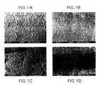
- FIGS. 1A-1Gshow the surface condition after different post treatments.
- the inventorshave made great efforts to find means to reduce the smearing of workpiece material onto the cutting edge in order to improve edge flaking and flank wear resistance. It has been found by comparative cutting tests with different top layers that Al 2 O 3 is less prone to smearing than layers of the type TiC x N y 0 z . In particular, fine-grained smooth ⁇ -Al 2 O 3 is very suitable as a coating material along the cutting edge in order minimize smearings and thereby reduce the risk of edge-line flaking.
- the fine-grained ⁇ -Al 2 O 3 layersmay, e.g., be any of the types disclosed in U.S. patent Ser. Nos. 08/159,217 (our reference: 024000-993) and 08/366,107 (our reference: 024444-093) or most likely also any other fine-grained ⁇ -Al 2 O 3 -layer with other preferred growth direction.
- edge identification and improved flank wearcan be obtained by applying a top layer of TiC x N y O z .
- a top layer of TiC x N y O zwill severely increase smearing along the edge-line when machining the difficult materials mentioned above.
- the inventorshave solved this problem by mechanically removing the TiC x N y O z -layer either from only the cutting edge-line or from both the rake face and the cutting edge-line.
- a cutting tool insertcomprising a body of generally polygonal or round shape having an upper face, an opposite face and at least one clearance face intersecting said upper and lower faces to define cutting edges made of cemented carbide, titanium based carbonitride or ceramics.
- the insertis at least partly coated with at least two refractory layers.
- Oneis a fine-grained, grain size 0.5-4.0 ⁇ m, preferably 0.5-2.0 ⁇ m, ⁇ -Al 2 O 3 -layer being the top layer along the cutting edge-line and the other is a TiC x N y O z - or a ZrC x N y -cutting-layer, preferably a TiN-, ZrN-, TiCN- and/or TiC-layer being the top layer on the clearance face.
- the ⁇ -Al 2 O 3 -layerpreferably has a texture in the (012)-direction or (104)-direction.
- TC for the set of (012) crystal planesis larger than 1.3, preferably larger than 1.5, and for the set of (104) crystal planes TC is larger than 1.5, preferably larger than 2.5, and most preferably larger than 3.0.
- the ⁇ -Al 2 O 3 -layerhas a thickness of 2-12 ⁇ m, preferably 4-8 ⁇ m.
- the other layerhas a thickness of 0.1-5 ⁇ m, preferably 1-4 ⁇ m.
- the total thickness of the coating including also other layersis ⁇ 20 ⁇ m.
- a cutting tool insert made of cemented carbide, titanium based carbonitride or ceramicsis at least partly coated with at least two refractory layers of which the next outermost layer is a fine-grained ⁇ -Al 2 O 3 -layer and the outermost is a MeC x N y 0 z -layer, where Me is a metal selected from the group consisting of metals in the groups IVB, VB, VIB of the Periodic Table, preferably Ti or Zr.
- This top MeC x N y O z -layeris removed along the cutting edge-line or on the cutting edge-line as well as the rake face leaving said layer essentially untouched on the clearance face.
- the methods used to remove the layercan be: brushing with a brush with straws containing, e.g., SiC or other grinding media, polishing with diamond paste, controlled directed blasting with, e.g., Al 2 O 3 -powders with or without masking off the clearance face. Also combinations of these methods are possible.
- the aim of the mechanical treatment in the presently claimed inventionis as mentioned to remove the top TiC x N y O z -layer and expose the fine-grained ⁇ -Al 2 O 3 layer along the edge or also the entire rake face. A reduction of coating thickness along the edge-line is not desired.
- the used mechanical methodshould be so gentle that only the top TiC x N y O z -layer is removed leaving the Al 2 O 3 at the edge-line as untouched as possible.
- Cemented carbide cutting inserts CNMG 120408-QM with the composition 5.5% Co, 8.6% cubic carbides (TiC-TaC-NbC) and balance WCwere coated with CVD-technique according to the following sequence: 0.7 ⁇ m TiC, 0.5 ⁇ m Ti(CO), 8.0 ⁇ m Ti(CN), 3.0 ⁇ m Al 2 O 3 and 2.8 ⁇ m TiN.
- the Al 2 O 3 -layerwas deposited with a method that gives a fine-grained ⁇ -Al 2 O 3 layer according to U.S. Ser. No. 08/159,217 (our reference: 024000-993).
- the TiN-layerwas deposited at 400 mbar and the other layers according to prior art techniques.
- the coated insertswere post treated with different methods according to below:
- Variant 1ANo post treatment.
- Variant 1BWet blasting with 150 mesh Al 2 O 3 -grits at 1.0 bar.
- Variant 1CWet blasting with 150 mesh Al 2 O 3 -grits at 1.5 bar.
- Variant 1DWet blasting with 150 mesh Al 2 O 3 -grits at 2.0 bar.
- Variant 1EWet blasting with 325 mesh Al 2 O 3 -grits at 2.0 bar.
- Variant 1FBrushing with a cylindrical nylon brush containing SiC.
- Variant 1GAs 1F but with the center of the brush closer to the insert in order to get more efficient treatment.
- Variant 1BA much smoother surface than 1A. The TiN-layer covering the whole surface of the insert.
- Variant 1CA much smoother surface than 1A.
- Variant 1DA much smoother surface than 1A.
- the TiN-layeris removed along the whole edge-line exposing the Al 2 O 3 -layer.
- Variant 1EAs 1B.
- Variant 1FA much smoother surface than 1A. The TiN-layer covering the whole surface of the insert.
- Variant 1GA much smoother surface than 1A.
- the TiN layeris removed along the whole edge-line exposing the Al 2 O 3 -layer.
- FIGS. 1A-1GThe surface condition of the variants is illustrated by FIGS. 1A-1G .
- Cemented carbide cutting inserts CNMG 120408-QM with the composition 5.5% Co, 8.6% cubic carbides (TiC-TaC-NbC) and balance WCwere coated with CVD-technique according to the following sequence: 0.6 ⁇ m TiC, 0.4 ⁇ m Ti(CO), 8.1 ⁇ m Ti(CN), 8.1 ⁇ m on Al 2 O 3 and 0.9 ⁇ m TiN.
- the Al 2 O 3 -layerwas deposited with a method that gives a fine-grained ⁇ -Al 2 O 3 layer according to U.S. Ser. No. 08/159,217 (our reference: 024000-993).
- the TiN-layerwas deposited at 400 mbar and the other layers according to prior art techniques.
- the coated insertswere post treated with different methods according to below:
- Variant 2ANo post treatment.
- Variant 2BWet blasting with 150 mesh Al 2 O 3 -grits resulting in a smoother surface. Here the top TiN-layer was removed along the edge-line as well as on the whole rake face exposing the black Al 2 O 3 -layer.
- Variant 2CBrushing with a cylindrical SiC-containing nylon brush. This treatment resulted in a smooth surface with only the top TiN-layer removed along the edge-line exposing the Al 2 O 3 .
- Cemented carbide cutting inserts CNMG 120408-QM with the composition 5.5% Co, 8.6% cubic carbides (TiC-TaC-NbC) and balance WCwere coated with CVD-technique according to the following sequence: 1.0 ⁇ m TiC, 0.4 ⁇ m Ti(CO), 7.9 ⁇ m Ti(CN) and 5.5 ⁇ m Al 2 O 3 .
- the Al 2 O 3 -layerwas deposited with a method that gives a fine-grained ⁇ -Al 2 O 3 layer according to U.S. Ser. No. 08/159,217 (our reference: 024000-993).
- the insertswere treated by wet blasting with 150 mesh Al 2 O 3 -grits (Variant 3).
- Cemented carbide cutting inserts CNMG 120408-QM with the composition 6.5% Co, 8.7% cubic carbides (TiC-TaC-NbC) and balance WC and with a 25 ⁇ m thick binder phase enriched zonewere coated with CVD-technique according to the following sequence: 7.9 ⁇ m TiC, 4.2 ⁇ m Al 2 O 3 and 3.5 ⁇ m TiC.
- the Al 2 O 3 -layerwas deposited with a method that gives a fine-grained ⁇ -Al 2 O 3 -layer according to U.S. Ser. No. 08/159,217 (our reference: 024000-993).
- Variant 4ANo post treatment.
- Variant 4BThe inserts were brushed with a cylindrical SiC-containing nylon brush, resulting in a smooth surface exposing the Al 2 O 3 -layer along the whole edge-line.
- Cemented carbide cutting inserts CNMG 120408-QM with the composition 6.5% Co, 8.7% cubic carbides (TiC-TaC-NbC) and balance WC and with a 25 ⁇ m thick binder phase enriched surface zonewere coated with CVD-technique according to the following sequence: 7.0 ⁇ m TiC and 5.1 ⁇ m Al 2 O 3 .
- the Al 2 O 3 -layerwas deposited with a method that gives a fine-grained ⁇ -Al 2 O 3 layer according to U.S. Ser. No. 08/159,217 (our reference: 024000-993).
- the insertswere treated by wet blasting with 150 mesh Al 2 O 3 -grits (Variant 5).
- Cemented carbide cutting inserts CNMG 120408-QM with the composition 6.5% Co, 8.7% cubic carbides (TiC-TaC-NbC) and balance WC and with a 25 ⁇ m thick binder phase enriched surface zonewere coated with CVD-technique according to the following sequence: 5.4 ⁇ m Ti(CN), 5.3 ⁇ m Al 2 O 3 and 1.3 ⁇ m TiN.
- the Al 2 O 3 -layerwas deposited according to prior art technique resulting in a layer of mixed ⁇ - and ⁇ -polymorphs.
- the TiN-layerwas deposited at 400 mbar and the other layers according to prior art techniques.
- Variant 6ANot post treated.
- Variant 6BWet blasting with 150 mesh Al 2 O 3 -grits resulting in a smoother surface and the top TiN-layer removed along the edge-line as well as on the whole rake face exposing the Al 2 O 3 .
- Variant 6CBrushing with a cylindrical SiC-containing nylon brush resulting in a smooth surface and exposing the Al 2 O 3 -layer along the whole edge-line.
- the insertswere run one cut over the workpiece. The results below are expressed as percentage of the edge-line in cut that obtained flaking of the coating.
- Cutting inserts from Examples 4 and 5were run in longitudinal turning of a ball bearing steel SKF 25B.
- the flank wearwas measured after 2.5 min in order to study the initial wear.
Landscapes
- Chemical & Material Sciences (AREA)
- Engineering & Computer Science (AREA)
- Mechanical Engineering (AREA)
- Organic Chemistry (AREA)
- Chemical Kinetics & Catalysis (AREA)
- Materials Engineering (AREA)
- Metallurgy (AREA)
- General Chemical & Material Sciences (AREA)
- Inorganic Chemistry (AREA)
- Cutting Tools, Boring Holders, And Turrets (AREA)
- Chemical Vapour Deposition (AREA)
- Cookers (AREA)
- Polishing Bodies And Polishing Tools (AREA)
- Laminated Bodies (AREA)
- Chemical Treatment Of Metals (AREA)
- Inorganic Insulating Materials (AREA)
- Ceramic Products (AREA)
Abstract
Description
This application is a reissue of U.S. Pat. No.5,861,210, which claims the benefit of priority to Swedish Application No.9402543-4 filed Jul.20,1994.
The presently claimed invention relates to an Al2O3-coated cutting tool suitable for machining of metals by turning, milling, drilling or by similar chipforming machining methods.
Modern high productivity chipforming machining of metals requires reliable tools with excellent wear properties. This has so far been achieved by employing a cemented carbide tool body coated with a wear resistant coating. The cemented carbide tool body is generally in the shape of an indexable insert clamped in a tool holder.
The most commonly used wear resistant layers are TiC, TiN, and Al2O3. Both single layer and multilayer coatings are employed. CVD, PVD or similar coating techniques are used for depositing the different layers onto the cemented carbide body.
During the past five to ten years, coated cemented carbide tools have been improved considerably with respect to reliability and tool life.
During, e.g., a turning and cutting operation, the coated tool is worn continuously on its rake face by the formed metal chip which causes crater wear. The machined workpiece also slides along the clearance face of the tool causing flank wear.
During high speed cutting, the tool edge may reach a very high temperature at the rake face. This leads to a diffusion type crater wear on the rake face of the tool. On the clearance face of the tool, the temperature is significantly lower mainly so that abrasive type wear occurs.
It is generally accepted that an Al2O3-layer performs best on the rake face due to its excellent ability to withstand diffusion type wear. Layers of the type MeCxNyOz, where Me is a metal selected from the group consisting of the Groups IVB, VB, and VIB of the Periodic Table, generally Ti and where (x+y+z)=1, which type is hereafter denoted by TiCxNyOz, generally performs better on the clearance face. Al2O3-layers on the other hand, wear relatively fast on the clearance face and develop flank wear relatively quickly on that face. The flank wear will be particularly large for thick, >4 μm, Al2O3-layers. Flank wear influences the machined surface and may therefore limit tool life. For TiCxNyOz-type layers, the situation is almost the reverse, that is, they exhibit low flank wear and faster crater wear than Al2O3.
It is desirable to have a tool with high wear resistance on both the clearance face and on the rake face at the same time.
Other factors influencing cutting performance of a coated tool include spalling or flaking of the coatings. Flaking accelerates tool wear, in particular the flank wear. Flaking may be the result of inferior coating adhesion or it may be due to the smearing or welding of workpiece material onto the cutting edge and a successive withdrawal of the coating. This may occur when the adhesion strength between the chip formed and the coating material is sufficiently high.
Some steels are more difficult to machine than others due to smearing and resulting flaking, for example, stainless steel and low carbon steel.
Nowadays, less machining per each component is needed. The requirements for high surface finish of the machined component only allow tools with a clean smooth cutting edge-line with very little developed wear to be used. It is becoming more and more difficult for the machine operator by the naked eye to differentiate between a little used and an unused cutting edge (“edge identification”). This is particularly difficult if the top layer is Al2O3which color is dark grey or black. By mistake, using a used tool cutting edge, e.g., during an unmanned night shift run may cause component rejection or even unwanted production stops. Edge identification can more easily be done if the insert has a top layer of TiCxNyOzor in particular if the top layer is a goldish TiN-, ZrN- or HfN-layer.
In U.S. Pat. No. 4,643,620, the coating thickness is reduced along the edge by a mechanical treatment such as brushing, lapping or barrel polishing. The object is mainly to reduce the coating thickness along the cutting edge which is claimed to improve the toughness behavior of the cutting tool.
U.S. Pat. No. 4,966,501 discloses a method of reducing edge damages during cutting by reducing the coated surface roughness by employing a mechanical polishing, lapping or brush honing. This method is according to the findings of the present inventors not sufficient to minimize smearing.
It is an object of this invention to avoid or alleviate the problems of the prior art.
It is further an object of this invention to provide improvements in coated bodies with respect to the tendency of smearing/welding of workpiece material onto the cutting edge, cutting edge flaking resistance, simultaneous high resistance to crater and flank wear and to make “used edge identification” possible.
In one aspect of the invention there is provided a cutting tool insert made of cemented carbide, titanium based carbonitride or ceramics comprising a body of generally polygonal or round shape having an upper face, an opposite face and at least one clearance face intersecting said upper and lower faces to define a cutting edge, said insert being at least partly coated with at least two refractory layers of which one is a fine-grained α-Al2O3-layer and the other is an MeCxNyOz-layer where Me is a metal selected from the group consisting of metals in the Groups IVB, VB and VIB of the Periodic Table and (x+y+z)=1, said Al2O3-layer being the top layer along the cutting edge-line and said MeCxNyOz-layer being the top layer on the clearance face.
In another aspect of the invention there is provided a method of making a cutting tool insert comprising a body of generally polygonal or round shape having an upper face, an opposite face and at least one clearance face intersecting said upper and lower faces to define a cutting edge, said body made of cemented carbide, titanium based carbonitride or ceramics comprising coating said insert at least partially with at least two refractory layers of which the next outermost is a fine-grained α-Al2O3-layer and a top MeCxNyOz-layer where Me is a metal selected from the group consisting of metals in the Groups IVB, VB, VIB of the Periodic Table and (x+y+z)=1 removing said top MeCxNyOz-layer at least along the cutting edge-line leaving said layer essentially untouched on the clearance face.
The invention is illustrated byFIGS. 1A-1G which show the surface condition after different post treatments.
The inventors have made great efforts to find means to reduce the smearing of workpiece material onto the cutting edge in order to improve edge flaking and flank wear resistance. It has been found by comparative cutting tests with different top layers that Al2O3is less prone to smearing than layers of the type TiCxNy0z. In particular, fine-grained smooth α-Al2O3is very suitable as a coating material along the cutting edge in order minimize smearings and thereby reduce the risk of edge-line flaking.
The fine-grained α-Al2O3layers may, e.g., be any of the types disclosed in U.S. patent Ser. Nos. 08/159,217 (our reference: 024000-993) and 08/366,107 (our reference: 024444-093) or most likely also any other fine-grained α-Al2O3-layer with other preferred growth direction.
Although tools with a top layer of a fine-grained α-Al2O3, such as described in the above patent applications have excellent cutting properties they do not always comply with today's requirements since they, e.g., suffer from the following drawbacks:
- “used edge identification” is difficult with the naked eye
- high initial flank wear is generally obtained for tools with Al2O3top layers >4 μm.
As mentioned above, edge identification and improved flank wear can be obtained by applying a top layer of TiCxNyOz. However, such a top layer will severely increase smearing along the edge-line when machining the difficult materials mentioned above.
The inventors have solved this problem by mechanically removing the TiCxNyOz-layer either from only the cutting edge-line or from both the rake face and the cutting edge-line.
By employing this method and keeping the TiCxNyOz-layer intact on the clearance face, several requirements have been fulfilled simultaneously:
- excellent wear resistance simultaneously on the rake face and on the clearance face;
- excellent flaking resistance; and
- easily identifiable used cutting edges.
According to the presently claimed invention, there now exists a cutting tool insert comprising a body of generally polygonal or round shape having an upper face, an opposite face and at least one clearance face intersecting said upper and lower faces to define cutting edges made of cemented carbide, titanium based carbonitride or ceramics. The insert is at least partly coated with at least two refractory layers. One is a fine-grained, grain size 0.5-4.0 μm, preferably 0.5-2.0 μm, α-Al2O3-layer being the top layer along the cutting edge-line and the other is a TiCxNyOz- or a ZrCxNy-cutting-layer, preferably a TiN-, ZrN-, TiCN- and/or TiC-layer being the top layer on the clearance face. The α-Al2O3-layer preferably has a texture in the (012)-direction or (104)-direction. A Texture Coefficient, TC, can be defined as:
where
where
- I(hkl)=measured intensity of the (hkl) reflection.
- I0(hkl)=standard intensity of the ASTM standard powder pattern diffraction data.
- n=number of reflections used in the calculation, (hkl) reflections used are: (012), (104), (110), (113), (024), (116).
According to the invention, TC for the set of (012) crystal planes is larger than 1.3, preferably larger than 1.5, and for the set of (104) crystal planes TC is larger than 1.5, preferably larger than 2.5, and most preferably larger than 3.0.
The α-Al2O3-layer has a thickness of 2-12 μm, preferably 4-8 μm. The other layer has a thickness of 0.1-5 μm, preferably 1-4 μm. The total thickness of the coating including also other layers is <20 μm.
According to the method of the presently claimed invention, a cutting tool insert made of cemented carbide, titanium based carbonitride or ceramics is at least partly coated with at least two refractory layers of which the next outermost layer is a fine-grained α-Al2O3-layer and the outermost is a MeCxNy0z-layer, where Me is a metal selected from the group consisting of metals in the groups IVB, VB, VIB of the Periodic Table, preferably Ti or Zr. This top MeCxNyOz-layer is removed along the cutting edge-line or on the cutting edge-line as well as the rake face leaving said layer essentially untouched on the clearance face.
The methods used to remove the layer can be: brushing with a brush with straws containing, e.g., SiC or other grinding media, polishing with diamond paste, controlled directed blasting with, e.g., Al2O3-powders with or without masking off the clearance face. Also combinations of these methods are possible.
The aim of the mechanical treatment in the presently claimed invention is as mentioned to remove the top TiCxNyOz-layer and expose the fine-grained α-Al2O3layer along the edge or also the entire rake face. A reduction of coating thickness along the edge-line is not desired. The used mechanical method should be so gentle that only the top TiCxNyOz-layer is removed leaving the Al2O3at the edge-line as untouched as possible.
The invention is additionally illustrated in connection with the following Examples which are to be considered as illustrative of the presently claimed invention. It should be understood, however, that the invention is not limited to the specific details of the Examples.
Cemented carbide cutting inserts CNMG 120408-QM with the composition 5.5% Co, 8.6% cubic carbides (TiC-TaC-NbC) and balance WC were coated with CVD-technique according to the following sequence: 0.7 μm TiC, 0.5 μm Ti(CO), 8.0 μm Ti(CN), 3.0 μm Al2O3and 2.8 μm TiN.
The Al2O3-layer was deposited with a method that gives a fine-grained α-Al2O3layer according to U.S. Ser. No. 08/159,217 (our reference: 024000-993). The TiN-layer was deposited at 400 mbar and the other layers according to prior art techniques.
The coated inserts were post treated with different methods according to below:
Variant 1A: No post treatment.
Variant 1B: Wet blasting with 150 mesh Al2O3-grits at 1.0 bar.
Variant 1C: Wet blasting with 150 mesh Al2O3-grits at 1.5 bar.
Variant 1D: Wet blasting with 150 mesh Al2O3-grits at 2.0 bar.
Variant 1E: Wet blasting with 325 mesh Al2O3-grits at 2.0 bar.
Variant 1F: Brushing with a cylindrical nylon brush containing SiC.
Variant 1G: As 1F but with the center of the brush closer to the insert in order to get more efficient treatment.
The different treatments resulted in different degrees of thinning and smoothness of the outer TiN-layer:
Variant 1B: A much smoother surface than 1A. The TiN-layer covering the whole surface of the insert.
Variant 1C: A much smoother surface than 1A. The TiN-layer covering the whole surface of the insert.
Variant 1D: A much smoother surface than 1A. The TiN-layer is removed along the whole edge-line exposing the Al2O3-layer.
Variant 1E: As 1B.
Variant 1F: A much smoother surface than 1A. The TiN-layer covering the whole surface of the insert.
Variant 1G: A much smoother surface than 1A. The TiN layer is removed along the whole edge-line exposing the Al2O3-layer.
The surface condition of the variants is illustrated byFIGS. 1A-1G .
Cemented carbide cutting inserts CNMG 120408-QM with the composition 5.5% Co, 8.6% cubic carbides (TiC-TaC-NbC) and balance WC were coated with CVD-technique according to the following sequence: 0.6 μm TiC, 0.4 μm Ti(CO), 8.1 μm Ti(CN), 8.1 μm on Al2O3and 0.9 μm TiN.
The Al2O3-layer was deposited with a method that gives a fine-grained α-Al2O3layer according to U.S. Ser. No. 08/159,217 (our reference: 024000-993). The TiN-layer was deposited at 400 mbar and the other layers according to prior art techniques.
The coated inserts were post treated with different methods according to below:
Variant 2A: No post treatment.
Variant 2B: Wet blasting with 150 mesh Al2O3-grits resulting in a smoother surface. Here the top TiN-layer was removed along the edge-line as well as on the whole rake face exposing the black Al2O3-layer.
Variant 2C: Brushing with a cylindrical SiC-containing nylon brush. This treatment resulted in a smooth surface with only the top TiN-layer removed along the edge-line exposing the Al2O3.
Cemented carbide cutting inserts CNMG 120408-QM with the composition 5.5% Co, 8.6% cubic carbides (TiC-TaC-NbC) and balance WC were coated with CVD-technique according to the following sequence: 1.0 μm TiC, 0.4 μm Ti(CO), 7.9 μm Ti(CN) and 5.5 μm Al2O3.
The Al2O3-layer was deposited with a method that gives a fine-grained α-Al2O3layer according to U.S. Ser. No. 08/159,217 (our reference: 024000-993).
The inserts were treated by wet blasting with 150 mesh Al2O3-grits (Variant 3).
Cemented carbide cutting inserts CNMG 120408-QM with the composition 6.5% Co, 8.7% cubic carbides (TiC-TaC-NbC) and balance WC and with a 25 μm thick binder phase enriched zone were coated with CVD-technique according to the following sequence: 7.9 μm TiC, 4.2 μm Al2O3and 3.5 μm TiC.
The Al2O3-layer was deposited with a method that gives a fine-grained α-Al2O3-layer according to U.S. Ser. No. 08/159,217 (our reference: 024000-993).
Variant 4A: No post treatment.
Variant 4B: The inserts were brushed with a cylindrical SiC-containing nylon brush, resulting in a smooth surface exposing the Al2O3-layer along the whole edge-line.
Cemented carbide cutting inserts CNMG 120408-QM with the composition 6.5% Co, 8.7% cubic carbides (TiC-TaC-NbC) and balance WC and with a 25 μm thick binder phase enriched surface zone were coated with CVD-technique according to the following sequence: 7.0 μm TiC and 5.1 μm Al2O3.
The Al2O3-layer was deposited with a method that gives a fine-grained α-Al2O3layer according to U.S. Ser. No. 08/159,217 (our reference: 024000-993).
The inserts were treated by wet blasting with 150 mesh Al2O3-grits (Variant 5).
Cemented carbide cutting inserts CNMG 120408-QM with the composition 6.5% Co, 8.7% cubic carbides (TiC-TaC-NbC) and balance WC and with a 25 μm thick binder phase enriched surface zone were coated with CVD-technique according to the following sequence: 5.4 μm Ti(CN), 5.3 μm Al2O3and 1.3 μm TiN.
The Al2O3-layer was deposited according to prior art technique resulting in a layer of mixed α- and κ-polymorphs. The TiN-layer was deposited at 400 mbar and the other layers according to prior art techniques.
Variant 6A: Not post treated.
Variant 6B: Wet blasting with150 mesh Al2O3-grits resulting in a smoother surface and the top TiN-layer removed along the edge-line as well as on the whole rake face exposing the Al2O3.
Variant 6C: Brushing with a cylindrical SiC-containing nylon brush resulting in a smooth surface and exposing the Al2O3-layer along the whole edge-line.
Tool inserts from examples 1-6 were tested with respect of edge-line flaking in a facing operation in an alloyed steel (AISI 1518, W-no. 1,0580). The shape of the workpiece was such that the cutting edge was intermitted three times during each revolution. Cutting data:
- Cutting speed: 130-220 m/min
- Feed: 0.2 mm/rev
- Depth of cut: 2.0 mm
The inserts were run one cut over the workpiece. The results below are expressed as percentage of the edge-line in cut that obtained flaking of the coating.
| % Edge Line Flaking | |||
| Variant | Post Treatment | Al2O3Exposed | at edge |
| 1A | None | No | 63 |
| 1B | Blasted | No | 80 |
| 1C | Blasted | No | 84 |
| 1D | Blasted | Yes | 18 |
| 1E | Blasted | No | 70 |
| 1F | Brushed | No | 66 |
| 1G | Brushed | Yes | 0 |
| 2A | None | No | 57 |
| 2B | Blasted | Yes | 0 |
| 2C | Brushed | Yes | 0 |
| 3 | Blasted | Yes | 0 |
| 4A | None | No | 87 |
| 4B | Brushed | Yes | 0 |
| 5 | Blasted | Yes | 0 |
| 6A | None | No | 83 |
| 6B | Blasted | Yes | 27 |
| 6C | Brushed | Yes | 33 |
As can be seen from above, the best results have been obtained when the fine-grained α-Al2O3-layer has been exposed at the edge-line. Post treatment resulting in a smoother coating surface but not exposure of the α-Al2O3does not result in any improvement of the flaking resistance. Variants 6B and 6C with the α/κ-polymorphs exposed at the edge-line do not obtain as good flaking resistance as the Variants with α-Al2O3-layer exposed at the edge-line.
Cutting inserts from Examples 4 and 5 were run in longitudinal turning of a ball bearing steel SKF 25B.
- Cutting data:
- Cutting speed: 180 m/min
- Feed: 0.36 mm/rev
- Depth of cut: 2,0 mm, coolant was used
The flank wear was measured after 2.5 min in order to study the initial wear.
| Variant | Flank Wear, mm | ||
| 4B | 0.13 | ||
| 5 | 0.20 | ||
This Example illustrates the improved flank wear resistance due to the top TiC layer on the flank face.
The principles, preferred embodiments and modes of operation of the presently claimed invention have been described in the foregoing specification. The invention which is intended to be protected herein, however, is not to be construed as limited to the particular forms disclosed, since these are to be regarded as illustrative rather than restrictive. Variations and changes may be made by those skilled in the art without departing from the spirit of the invention.
Claims (22)
1. A cutting tool insert made of cemented carbide, titanium based carbonitride or ceramics having an improved resistance to smearing of the workpiece material on the cutting edge comprising a body of generally polygonal or round shape having an upper face, an opposite face and at least one clearance face intersecting said upper and lower faces to define a cutting edge, said insert being at least partly coated with at least two refractory layers of which one is a fine-grained α-Al2O3-layer and the other is an MeCxNyOz-layer where Me is a metal selected from the group consisting of the metals in the Groups IVB, VB and VIB of the Periodic Table and (x+y+z)=1, said Al2O3-layer being the top layer along the cutting edge-line and on the upper face and said MeCxNyOz-layer being the top layer on the clearance face.
2. The cutting tool insert ofclaim 1 wherein said α-Al2O3-layer has a texture in the (012)-direction or (104)-direction.
3. The cutting tool insert ofclaim 1 wherein Me is Ti or Zr.
4. The cutting tool insert ofclaim 3 wherein the layer on the clearance face is TiN, ZrN, TiCN or TiC.
5. The cutting tool insert ofclaim 1 wherein a fine-grained α-Al2O3layer is present between the body and the MeCxNyOzlayer on the clearance face.
6. The cutting tool insert ofclaim 1 wherein the Al2O3thickness is 2-12 μm.
7. A method of making a cutting tool insert comprising a body of generally polygonal or round shape having an upper face, an opposite face and at least one clearance face intersecting said upper and lower faces to define a cutting edge, said body made of cemented carbide, titanium based carbonitride or ceramics comprising coating said insert at least partially with at least two refractory layers of which the next outermost is a fine-grained α-Al2O3-layer and a top MeCxNyOz-layer where Me is a metal selected from the group consisting of metals in the groups IVB, VB, VIB of the Periodic Table and (x+y+z)=1 and removing said top MeCxNyOz-layer at least along the cutting edge-line and on the upper face, leaving said layer essentially untouched on the clearance face.
8. The method ofclaim 7 wherein said top layer is removed by brushing with a brush containing SiC or by blasting with Al2O3-grits.
9. The method ofclaim 7 wherein said α-Al2O3-layer has a texture in the (012)-direction or (104)-direction.
10. The method ofclaim 7 wherein Me is Ti or Zr.
11. The method ofclaim 10 wherein said MeCxNyOz-layer comprises TiN, ZrN, TiCN or TiC.
12. The method ofclaim 7 wherein said α-Al2O3-layer thickness is 2-12 μm.
13. The method ofclaim 7 wherein said α-Al2O3-layer has a texture in the(012)-direction or(104)-direction and wherein Me is Ti or Zr.
14. The method ofclaim 13 wherein the MeCxNyOzlayer is TiN, ZrN, TiCN or TiC.
15. The method ofclaim 14 wherein the Al2O3thickness is2-12 μm.
16. The method ofclaim 14 wherein said upper layer is removed by blasting with Al2O3-grits.
17. The cutting tool insert ofclaim 1 wherein said α-Al2O3-layer has a texture in the(012)-direction or(104)-direction and wherein Me is Ti or Zr.
18. The cutting tool insert ofclaim 17 wherein the layer on the clearance face is TiN, ZrN, TiCN or TiC.
19. The cutting tool insert ofclaim 18 wherein a fine-grained α-Al2O3-layer is present between the body and the MeCxNyOzlayer on the clearance face.
20. The cutting tool insert ofclaim 19 wherein the Al2O3thickness is2-12 μm.
21. The cutting tool insert ofclaim 1 wherein the Al2O3-layer is the top layer on substantially the whole upper face.
22. The method ofclaim 7 wherein the MeCxNyOz-layer is removed from substantially the whole upper face.
Priority Applications (1)
| Application Number | Priority Date | Filing Date | Title |
|---|---|---|---|
| US11/653,420USRE41972E1 (en) | 1994-07-20 | 2007-01-16 | Aluminum oxide coated tool |
Applications Claiming Priority (4)
| Application Number | Priority Date | Filing Date | Title |
|---|---|---|---|
| SE9402543-4 | 1994-07-20 | ||
| SE9402543ASE509201C2 (en) | 1994-07-20 | 1994-07-20 | Aluminum oxide coated tool |
| US08/497,934US5861210A (en) | 1994-07-20 | 1995-07-05 | Aluminum oxide coated tool |
| US11/653,420USRE41972E1 (en) | 1994-07-20 | 2007-01-16 | Aluminum oxide coated tool |
Related Parent Applications (1)
| Application Number | Title | Priority Date | Filing Date |
|---|---|---|---|
| US08/497,934ReissueUS5861210A (en) | 1994-07-20 | 1995-07-05 | Aluminum oxide coated tool |
Publications (1)
| Publication Number | Publication Date |
|---|---|
| USRE41972E1true USRE41972E1 (en) | 2010-11-30 |
Family
ID=20394780
Family Applications (2)
| Application Number | Title | Priority Date | Filing Date |
|---|---|---|---|
| US08/497,934CeasedUS5861210A (en) | 1994-07-20 | 1995-07-05 | Aluminum oxide coated tool |
| US11/653,420Expired - LifetimeUSRE41972E1 (en) | 1994-07-20 | 2007-01-16 | Aluminum oxide coated tool |
Family Applications Before (1)
| Application Number | Title | Priority Date | Filing Date |
|---|---|---|---|
| US08/497,934CeasedUS5861210A (en) | 1994-07-20 | 1995-07-05 | Aluminum oxide coated tool |
Country Status (11)
| Country | Link |
|---|---|
| US (2) | US5861210A (en) |
| EP (1) | EP0693574B2 (en) |
| JP (1) | JP3761932B2 (en) |
| KR (1) | KR100385275B1 (en) |
| CN (1) | CN1066369C (en) |
| AT (1) | ATE164889T1 (en) |
| BR (1) | BR9503375A (en) |
| DE (1) | DE69501984T3 (en) |
| IL (1) | IL114674A (en) |
| RU (1) | RU2131329C1 (en) |
| SE (1) | SE509201C2 (en) |
Cited By (25)
| Publication number | Priority date | Publication date | Assignee | Title |
|---|---|---|---|---|
| US8345441B1 (en) | 2011-10-03 | 2013-01-01 | Invensas Corporation | Stub minimization for multi-die wirebond assemblies with parallel windows |
| US8405207B1 (en) | 2011-10-03 | 2013-03-26 | Invensas Corporation | Stub minimization for wirebond assemblies without windows |
| US8436477B2 (en) | 2011-10-03 | 2013-05-07 | Invensas Corporation | Stub minimization using duplicate sets of signal terminals in assemblies without wirebonds to package substrate |
| US8436457B2 (en) | 2011-10-03 | 2013-05-07 | Invensas Corporation | Stub minimization for multi-die wirebond assemblies with parallel windows |
| US8441111B2 (en) | 2011-10-03 | 2013-05-14 | Invensas Corporation | Stub minimization for multi-die wirebond assemblies with parallel windows |
| US8502390B2 (en) | 2011-07-12 | 2013-08-06 | Tessera, Inc. | De-skewed multi-die packages |
| US8513813B2 (en) | 2011-10-03 | 2013-08-20 | Invensas Corporation | Stub minimization using duplicate sets of terminals for wirebond assemblies without windows |
| US8513817B2 (en) | 2011-07-12 | 2013-08-20 | Invensas Corporation | Memory module in a package |
| US8525327B2 (en) | 2011-10-03 | 2013-09-03 | Invensas Corporation | Stub minimization for assemblies without wirebonds to package substrate |
| US8670261B2 (en) | 2011-10-03 | 2014-03-11 | Invensas Corporation | Stub minimization using duplicate sets of signal terminals |
| US8787034B2 (en) | 2012-08-27 | 2014-07-22 | Invensas Corporation | Co-support system and microelectronic assembly |
| US8823165B2 (en) | 2011-07-12 | 2014-09-02 | Invensas Corporation | Memory module in a package |
| US8848392B2 (en) | 2012-08-27 | 2014-09-30 | Invensas Corporation | Co-support module and microelectronic assembly |
| US8848391B2 (en) | 2012-08-27 | 2014-09-30 | Invensas Corporation | Co-support component and microelectronic assembly |
| US8917532B2 (en) | 2011-10-03 | 2014-12-23 | Invensas Corporation | Stub minimization with terminal grids offset from center of package |
| US8981547B2 (en) | 2011-10-03 | 2015-03-17 | Invensas Corporation | Stub minimization for multi-die wirebond assemblies with parallel windows |
| US9070423B2 (en) | 2013-06-11 | 2015-06-30 | Invensas Corporation | Single package dual channel memory with co-support |
| US9123555B2 (en) | 2013-10-25 | 2015-09-01 | Invensas Corporation | Co-support for XFD packaging |
| US9281296B2 (en) | 2014-07-31 | 2016-03-08 | Invensas Corporation | Die stacking techniques in BGA memory package for small footprint CPU and memory motherboard design |
| EP2570510B1 (en) | 2011-09-16 | 2016-03-30 | Walter AG | Sulfur containing alpha-alumina coated cutting tool |
| US9368477B2 (en) | 2012-08-27 | 2016-06-14 | Invensas Corporation | Co-support circuit panel and microelectronic packages |
| US9484080B1 (en) | 2015-11-09 | 2016-11-01 | Invensas Corporation | High-bandwidth memory application with controlled impedance loading |
| US9679613B1 (en) | 2016-05-06 | 2017-06-13 | Invensas Corporation | TFD I/O partition for high-speed, high-density applications |
| US9691437B2 (en) | 2014-09-25 | 2017-06-27 | Invensas Corporation | Compact microelectronic assembly having reduced spacing between controller and memory packages |
| US11213893B2 (en)* | 2016-06-29 | 2022-01-04 | Sandvik Intellectual Property Ab | CVD coated cutting tool |
Families Citing this family (139)
| Publication number | Priority date | Publication date | Assignee | Title |
|---|---|---|---|---|
| SE509201C2 (en) | 1994-07-20 | 1998-12-14 | Sandvik Ab | Aluminum oxide coated tool |
| SE514177C2 (en)* | 1995-07-14 | 2001-01-15 | Sandvik Ab | Coated cemented carbide inserts for intermittent machining in low alloy steel |
| DE69619275T2 (en)* | 1995-11-30 | 2004-06-24 | Sandvik Ab | COATED ROTATABLE INSERT AND METHOD FOR THE PRODUCTION THEREOF |
| SE9504304D0 (en) | 1995-11-30 | 1995-11-30 | Sandvik Ab | Coated milling insert |
| ATE213282T1 (en)* | 1995-11-30 | 2002-02-15 | COATED CUTTING INSERT AND METHOD FOR PRODUCING SAME | |
| USRE40005E1 (en) | 1996-09-06 | 2008-01-15 | Sandvik Intellectual Property Ab | Coated cutting insert |
| SE509560C2 (en)* | 1996-09-06 | 1999-02-08 | Sandvik Ab | Coated cemented carbide inserts for machining cast iron |
| SE511211C2 (en)* | 1996-12-20 | 1999-08-23 | Sandvik Ab | A multilayer coated polycrystalline cubic boron nitride cutting tool |
| US6015614A (en)* | 1997-11-03 | 2000-01-18 | Seco Tools Ab | Cemented carbide body with high wear resistance and extra tough behavior |
| SE520802C2 (en) | 1997-11-06 | 2003-08-26 | Sandvik Ab | Cutting tool coated with alumina and process for its manufacture |
| US6293739B1 (en)* | 1998-04-14 | 2001-09-25 | Sumitomo Electric Industries, Ltd. | Coated cemented carbide cutting tool |
| JP2000042806A (en)* | 1998-07-31 | 2000-02-15 | Toshiba Tungaloy Co Ltd | Laminated coated body for cutting tool |
| US6251508B1 (en)* | 1998-12-09 | 2001-06-26 | Seco Tools Ab | Grade for cast iron |
| US6221469B1 (en)* | 1998-12-09 | 2001-04-24 | Seco Tools Ab | Grade for steel |
| SE516071C2 (en) | 1999-04-26 | 2001-11-12 | Sandvik Ab | Carbide inserts coated with a durable coating |
| SE519108C2 (en) | 1999-05-06 | 2003-01-14 | Sandvik Ab | Coated cutting tool for machining gray cast iron |
| SE520795C2 (en) | 1999-05-06 | 2003-08-26 | Sandvik Ab | Cutting tool coated with alumina and process for its manufacture |
| SE519921C2 (en) | 1999-05-06 | 2003-04-29 | Sandvik Ab | PVD coated cutting tool and method for its manufacture |
| SE520716C2 (en) | 1999-05-06 | 2003-08-12 | Sandvik Ab | A process for manufacturing a cutting tool coated with alumina |
| DE19924422C2 (en)* | 1999-05-28 | 2001-03-08 | Cemecon Ceramic Metal Coatings | Process for producing a hard-coated component and coated, after-treated component |
| US6638571B2 (en) | 2000-05-31 | 2003-10-28 | Mitsubishi Materials Corporation | Coated cemented carbide cutting tool member and process for producing the same |
| US6338894B1 (en)* | 2000-05-31 | 2002-01-15 | Mitsubishi Materials Corporation | Coated cemented carbide cutting tool member and process for producing the same |
| KR100688923B1 (en)* | 2000-07-12 | 2007-03-09 | 스미토모덴키고교가부시키가이샤 | Sheath cutting tool |
| DE10048899B4 (en)* | 2000-10-02 | 2004-04-08 | Walter Ag | Cutting insert with wear detection |
| SE519250C2 (en) | 2000-11-08 | 2003-02-04 | Sandvik Ab | Coated cemented carbide insert and its use for wet milling |
| SE519339C2 (en)* | 2000-11-22 | 2003-02-18 | Sandvik Ab | Cutting tools coated with alumina and ways of manufacturing the same |
| EP1311712A2 (en)* | 2001-03-27 | 2003-05-21 | Widia GmbH | Method for increasing compression stress or reducing internal tension stress of a cvd, pcvd or pvd layer and cutting insert for machining |
| US6733874B2 (en)* | 2001-08-31 | 2004-05-11 | Mitsubishi Materials Corporation | Surface-coated carbide alloy cutting tool |
| SE523826C2 (en)* | 2002-03-20 | 2004-05-25 | Seco Tools Ab | Cutter coated with TiAIN for high speed machining of alloy steels, ways of making a cutter and use of the cutter |
| SE526604C2 (en)* | 2002-03-22 | 2005-10-18 | Seco Tools Ab | Coated cutting tool for turning in steel |
| SE525581C2 (en)* | 2002-05-08 | 2005-03-15 | Seco Tools Ab | Cutting coated with alumina made with CVD |
| SE526603C3 (en) | 2003-01-24 | 2005-11-16 | Sandvik Intellectual Property | Coated cemented carbide insert |
| JP2004284003A (en)* | 2003-02-28 | 2004-10-14 | Mitsubishi Materials Corp | Surface-coated cermet cutting tool exhibiting excellent chipping resistance in hard coated layer |
| DE10319169A1 (en)* | 2003-04-29 | 2004-12-02 | Fette Gmbh | Process for producing desired surfaces or surface patterns for cutting tools |
| DE10332101B4 (en)* | 2003-07-15 | 2016-02-04 | Kennametal Inc. | Cutting tool and method for its production |
| GB0320148D0 (en) | 2003-08-28 | 2003-10-01 | Dormer Tools Sheffield Ltd | Partially coated drill tool |
| SE527724C2 (en)* | 2004-02-17 | 2006-05-23 | Sandvik Intellectual Property | Coated cutting tool for machining bimetal and method and use |
| DE102004010285A1 (en)* | 2004-03-03 | 2005-09-29 | Walter Ag | Coating for a cutting tool and manufacturing process |
| US7455918B2 (en)* | 2004-03-12 | 2008-11-25 | Kennametal Inc. | Alumina coating, coated product and method of making the same |
| EP1609883B1 (en) | 2004-06-24 | 2017-09-20 | Sandvik Intellectual Property AB | Coated metal cutting tool |
| KR100600573B1 (en)* | 2004-06-30 | 2006-07-13 | 한국야금 주식회사 | Surface-coated hard member for cutting tools / wear resistant tools |
| SE528109C2 (en)* | 2004-07-12 | 2006-09-05 | Sandvik Intellectual Property | Phantom inserts, especially for phase milling of steel sheet for oil pipes, and ways of manufacturing the same |
| SE528108C2 (en) | 2004-07-13 | 2006-09-05 | Sandvik Intellectual Property | Coated cemented carbide inserts, especially for turning steel, and ways of manufacturing the same |
| US20090211414A1 (en)* | 2004-07-29 | 2009-08-27 | Kyocera Corporation | Cutting Tool |
| EP1806192B1 (en)* | 2004-10-29 | 2014-04-23 | Sumitomo Electric Hardmetal Corp. | Edge replacement type cutting tip and method of manufacturing the same |
| US8012611B2 (en)* | 2004-10-29 | 2011-09-06 | Sumitomo Electric Hardmetal Corp. | Surface-coated cutting tool |
| SE528432C2 (en) | 2004-11-05 | 2006-11-14 | Seco Tools Ab | With aluminum oxide coated cutting tool inserts and method for making this |
| SE528430C2 (en)* | 2004-11-05 | 2006-11-14 | Seco Tools Ab | With aluminum oxide coated cutting tool inserts and method of making this |
| SE0500015D0 (en)* | 2004-11-08 | 2005-01-03 | Sandvik Ab | Coated inserts for wet milling |
| WO2006059551A1 (en)* | 2004-12-03 | 2006-06-08 | Sumitomo Electric Hardmetal Corp. | Edge replacement type cutting tip and method of manufacturing the same |
| KR100576321B1 (en)* | 2004-12-14 | 2006-05-03 | 한국야금 주식회사 | Tough Cutting Tools / Wear Resistant Tools |
| US7803464B2 (en)* | 2004-12-27 | 2010-09-28 | Sumitomo Electric Hardmetal Corp. | Surface-coated cutting tool |
| WO2006080154A1 (en)* | 2005-01-26 | 2006-08-03 | Sumitomo Electric Hardmetal Corp. | Edge replacement cutting tip and method of manufacturing the same |
| SE528672C2 (en)* | 2005-01-31 | 2007-01-16 | Sandvik Intellectual Property | Carbide inserts for durability-demanding short-hole drilling and ways of making the same |
| SE528696C2 (en)* | 2005-02-25 | 2007-01-23 | Sandvik Intellectual Property | CVD-coated carbide, cermet or ceramic cutter and ways of manufacturing the same |
| SE528891C2 (en)* | 2005-03-23 | 2007-03-06 | Sandvik Intellectual Property | Cut coated with a multi-layer of metal oxide |
| JPWO2006103982A1 (en)* | 2005-03-29 | 2008-09-04 | 住友電工ハードメタル株式会社 | Cutting edge replaceable cutting tip and manufacturing method thereof |
| SE528929C2 (en)* | 2005-04-18 | 2007-03-20 | Sandvik Intellectual Property | Cut coated with a layer system and method of making this |
| SE0602723L (en) | 2006-06-16 | 2007-12-17 | Sandvik Intellectual Property | Coated insert |
| SE529023C2 (en)* | 2005-06-17 | 2007-04-10 | Sandvik Intellectual Property | Coated carbide cutter |
| US20070298282A1 (en)* | 2005-06-17 | 2007-12-27 | Sandvik Intellectual Property Ab | Coated cutting tool insert |
| US7837416B2 (en) | 2005-07-29 | 2010-11-23 | Sumitomo Electric Hardmetal Corp. | Indexable cutting insert and method for producing the same |
| EP1762638B1 (en)* | 2005-09-09 | 2012-01-11 | Sandvik Intellectual Property AB | PVD coated cutting tool |
| SE529015C2 (en)* | 2005-09-09 | 2007-04-10 | Sandvik Intellectual Property | PVD coated cutting tool inserts made of cemented carbide |
| JP4853612B2 (en)* | 2005-09-26 | 2012-01-11 | 三菱マテリアル株式会社 | Manufacturing method of cutting throwaway tip made of surface coated cermet whose hard coating layer exhibits excellent chipping resistance in high speed cutting |
| JP4853613B2 (en)* | 2005-09-27 | 2012-01-11 | 三菱マテリアル株式会社 | Manufacturing method of cutting throwaway tip made of surface coated cermet whose hard coating layer exhibits excellent chipping resistance in high speed cutting |
| JP2007090470A (en)* | 2005-09-28 | 2007-04-12 | Mitsubishi Materials Corp | Surface coated cermet-made cutting throw-away tip having hard coating layer exhibiting excellent chipping resistance in high |
| JP4888688B2 (en)* | 2005-10-18 | 2012-02-29 | 三菱マテリアル株式会社 | Surface polishing method for cutting throwaway tip made of surface-covered cermet whose hard coating layer exhibits excellent chipping resistance in high-speed cutting |
| JP4888759B2 (en)* | 2005-10-19 | 2012-02-29 | 三菱マテリアル株式会社 | Surface polishing method for cutting throwaway tip made of surface-covered cermet whose hard coating layer exhibits excellent chipping resistance in high-speed cutting |
| JP4857705B2 (en)* | 2005-10-19 | 2012-01-18 | 三菱マテリアル株式会社 | Surface polishing method for surface-coated cermet cutting throwaway tips with hard coating layer providing excellent chipping resistance in high-speed cutting |
| EP1938919A4 (en)* | 2005-10-21 | 2012-01-11 | Sumitomo Elec Hardmetal Corp | Cutting edge replacement-type cutting chip |
| JP4857711B2 (en)* | 2005-10-26 | 2012-01-18 | 三菱マテリアル株式会社 | Surface polishing method for throated surface-coated cermet with a hard coating layer that exhibits excellent chipping resistance in high-speed cutting |
| JP4853820B2 (en)* | 2005-10-31 | 2012-01-11 | 三菱マテリアル株式会社 | Surface polishing method for throated surface-coated cermet with a hard coating layer that exhibits excellent chipping resistance in high-speed cutting |
| JP4888762B2 (en)* | 2005-10-31 | 2012-02-29 | 三菱マテリアル株式会社 | Surface polishing method for cutting throwaway tip made of surface-covered cermet whose hard coating layer exhibits excellent chipping resistance in high-speed cutting |
| JP4883389B2 (en)* | 2005-11-04 | 2012-02-22 | 三菱マテリアル株式会社 | Surface polishing method for throated surface-coated cermet with a hard coating layer that exhibits excellent chipping resistance in high-speed cutting |
| JP4888689B2 (en)* | 2005-11-04 | 2012-02-29 | 三菱マテリアル株式会社 | Surface polishing method for throated surface-coated cermet with a hard coating layer that exhibits excellent chipping resistance in high-speed cutting |
| JP4873289B2 (en)* | 2005-11-04 | 2012-02-08 | 三菱マテリアル株式会社 | Surface polishing method for throated surface-coated cermet with a hard coating layer that exhibits excellent chipping resistance in high-speed cutting |
| SE529200C2 (en)* | 2005-11-21 | 2007-05-29 | Sandvik Intellectual Property | Coated cutting, method of making and use |
| JP4797608B2 (en)* | 2005-12-02 | 2011-10-19 | 三菱マテリアル株式会社 | Surface-coated cutting insert and manufacturing method thereof |
| JP4779611B2 (en)* | 2005-12-02 | 2011-09-28 | 三菱マテリアル株式会社 | Manufacturing method of surface coated cutting insert |
| JP4900652B2 (en)* | 2005-12-12 | 2012-03-21 | 三菱マテリアル株式会社 | Surface polishing method for cutting throwaway tip made of surface-covered cermet whose hard coating layer exhibits excellent chipping resistance in high-speed cutting |
| JP4853621B2 (en)* | 2005-12-12 | 2012-01-11 | 三菱マテリアル株式会社 | Surface polishing method for cutting throwaway tip made of surface-covered cermet whose hard coating layer exhibits excellent chipping resistance in high-speed cutting |
| JP4900653B2 (en)* | 2005-12-12 | 2012-03-21 | 三菱マテリアル株式会社 | Surface polishing method for throated surface-coated cermet with a hard coating layer that exhibits excellent chipping resistance in high-speed cutting |
| JP4857751B2 (en)* | 2005-12-12 | 2012-01-18 | 三菱マテリアル株式会社 | Surface polishing method for throated surface-coated cermet with a hard coating layer that exhibits excellent chipping resistance in high-speed cutting |
| JP4853822B2 (en)* | 2005-12-13 | 2012-01-11 | 三菱マテリアル株式会社 | Surface polishing method for throated surface-coated cermet with a hard coating layer that exhibits excellent chipping resistance in high-speed cutting |
| JP4857752B2 (en)* | 2005-12-13 | 2012-01-18 | 三菱マテリアル株式会社 | Surface polishing method for cutting throwaway tip made of surface-covered cermet whose hard coating layer exhibits excellent chipping resistance in high-speed cutting |
| JP4849376B2 (en)* | 2005-12-14 | 2012-01-11 | 三菱マテリアル株式会社 | Manufacturing method of surface-coated cermet cutting tool that exhibits excellent chipping resistance in high-speed cutting of difficult-to-cut materials |
| JP4984513B2 (en)* | 2005-12-14 | 2012-07-25 | 三菱マテリアル株式会社 | Manufacturing method of surface-coated cermet cutting tool that exhibits excellent chipping resistance in high-speed cutting of difficult-to-cut materials |
| JP4863053B2 (en)* | 2005-12-20 | 2012-01-25 | 三菱マテリアル株式会社 | Manufacturing method of surface-coated cermet cutting tool that exhibits excellent chipping resistance in high-speed cutting of difficult-to-cut materials |
| JP4857759B2 (en)* | 2005-12-22 | 2012-01-18 | 三菱マテリアル株式会社 | Method for manufacturing a surface-coated cemented carbide cutting tool that exhibits excellent chipping resistance in high-speed cutting of difficult-to-cut materials |
| SE529857C2 (en)* | 2005-12-30 | 2007-12-11 | Sandvik Intellectual Property | Coated cemented carbide inserts, ways of making this and its use for deep hole drilling |
| JP4756469B2 (en)* | 2006-02-17 | 2011-08-24 | 三菱マテリアル株式会社 | Surface-coated cermet cutting throwaway tip that exhibits excellent chipping resistance due to high-speed cutting of hardened steel |
| JP4761138B2 (en)* | 2006-03-08 | 2011-08-31 | 三菱マテリアル株式会社 | Surface-coated cermet cutting throwaway tip that exhibits excellent chipping resistance due to high-speed cutting of hardened steel |
| JP4753076B2 (en)* | 2006-03-08 | 2011-08-17 | 三菱マテリアル株式会社 | Surface-coated cermet cutting throwaway tip that provides excellent chipping resistance with a hard coating layer in high-speed cutting of difficult-to-cut materials |
| JP4761141B2 (en)* | 2006-03-16 | 2011-08-31 | 三菱マテリアル株式会社 | Surface-coated cermet cutting throwaway tip that provides excellent chipping resistance with a hard coating layer in high-speed cutting of difficult-to-cut materials |
| JP4761140B2 (en)* | 2006-03-16 | 2011-08-31 | 三菱マテリアル株式会社 | Surface-coated cermet cutting throwaway tip that exhibits excellent chipping resistance due to high-speed cutting of hardened steel |
| JP4756471B2 (en)* | 2006-03-22 | 2011-08-24 | 三菱マテリアル株式会社 | Surface-coated cermet cutting throwaway tip that provides excellent chipping resistance in high-speed heavy cutting of hardened steel |
| JP4844872B2 (en)* | 2006-03-27 | 2011-12-28 | 三菱マテリアル株式会社 | Method for manufacturing a cutting throwaway tip made of surface-coated cermet that exhibits excellent chipping resistance with a hard coating layer in high-speed cutting of difficult-to-cut materials |
| JP4844873B2 (en)* | 2006-03-27 | 2011-12-28 | 三菱マテリアル株式会社 | Manufacturing method of cutting throwaway tip made of surface-covered cermet with excellent wear resistance of hard coating layer in high-speed cutting |
| CN100381402C (en)* | 2006-07-20 | 2008-04-16 | 上海交通大学 | Nanometer multilayer hard AlN/SiO2 film |
| US7967533B2 (en)* | 2006-08-31 | 2011-06-28 | Sumitomo Electric Hardmetal Corp. | Surface-coated cutting tool |
| SE530735C2 (en)* | 2006-10-18 | 2008-08-26 | Sandvik Intellectual Property | A coated carbide cutter, especially useful for turning steel |
| SE0602457L (en)* | 2006-11-20 | 2008-05-21 | Sandvik Intellectual Property | Coated inserts for milling in compact graphite iron |
| JP2008137129A (en)* | 2006-12-04 | 2008-06-19 | Mitsubishi Materials Corp | Surface coated cutting tool |
| JP2008137130A (en)* | 2006-12-04 | 2008-06-19 | Mitsubishi Materials Corp | Surface coated cutting tool |
| SE0602812L (en) | 2006-12-27 | 2008-06-28 | Sandvik Intellectual Property | CVD coated cemented carbide inserts for toughness requiring short hole drilling operations |
| SE0602815L (en)* | 2006-12-27 | 2008-06-28 | Sandvik Intellectual Property | Coated cemented carbide insert especially useful for heavy roughing operations |
| EP1944110B1 (en)* | 2007-01-15 | 2012-11-07 | Fraisa Holding AG | Method of processing and machining tools for the machining of workpieces by chip removal |
| SE531670C2 (en)* | 2007-02-01 | 2009-06-30 | Seco Tools Ab | Textured alpha-alumina coated cutting for metalworking |
| US8557406B2 (en) | 2007-06-28 | 2013-10-15 | Kennametal Inc. | Coated PCBN cutting insert, coated PCBN cutting tool using such coated PCBN cutting insert, and method for making the same |
| US8475944B2 (en)* | 2007-06-28 | 2013-07-02 | Kennametal Inc. | Coated ceramic cutting insert and method for making the same |
| US8080323B2 (en)* | 2007-06-28 | 2011-12-20 | Kennametal Inc. | Cutting insert with a wear-resistant coating scheme exhibiting wear indication and method of making the same |
| US20090004449A1 (en)* | 2007-06-28 | 2009-01-01 | Zhigang Ban | Cutting insert with a wear-resistant coating scheme exhibiting wear indication and method of making the same |
| KR101057106B1 (en)* | 2008-10-21 | 2011-08-16 | 대구텍 유한회사 | Cutting tool and its surface treatment method |
| EP2287359B1 (en) | 2009-07-03 | 2012-05-23 | Sandvik Intellectual Property AB | Coated cutting tool insert |
| DE202009014144U1 (en)* | 2009-10-19 | 2011-03-03 | Mader, Gert | notching |
| US8668982B2 (en) | 2009-11-10 | 2014-03-11 | Kennametal Inc. | Coated cutting insert and method for making the same |
| US8323783B2 (en) | 2009-11-10 | 2012-12-04 | Kennametal Inc. | Coated cutting insert and method for making the same |
| CN101837475B (en)* | 2010-04-28 | 2011-10-05 | 株洲钻石切削刀具股份有限公司 | Coated blade for processing aluminum material and preparation method thereof |
| DE202010009721U1 (en)* | 2010-07-01 | 2010-10-14 | Clarkson Gmbh | Cutting plate for a cutting tool |
| JP5590326B2 (en)* | 2011-01-05 | 2014-09-17 | 三菱マテリアル株式会社 | Diamond-coated cemented carbide drill |
| US8507082B2 (en) | 2011-03-25 | 2013-08-13 | Kennametal Inc. | CVD coated polycrystalline c-BN cutting tools |
| WO2013130740A1 (en)* | 2012-02-28 | 2013-09-06 | University Of Florida Research Foundation, Inc. | Systems and methods for extending cutting tool life |
| DE102012107130A1 (en) | 2012-08-03 | 2014-02-06 | Walter Ag | Cutting tool with wear detection layer |
| KR102178612B1 (en) | 2012-12-21 | 2020-11-13 | 산드빅 인터렉츄얼 프로퍼티 에이비 | Coated cutting tool and method for manufacturing the same |
| US9028953B2 (en) | 2013-01-11 | 2015-05-12 | Kennametal Inc. | CVD coated polycrystalline c-BN cutting tools |
| JP5568649B1 (en)* | 2013-01-22 | 2014-08-06 | 日本航空電子工業株式会社 | Cutlery tool |
| CN105102673B (en)* | 2013-03-21 | 2017-11-17 | 钴碳化钨硬质合金公司 | Coatings for Cutting Tools |
| WO2014153440A1 (en)* | 2013-03-21 | 2014-09-25 | Kennametal Inc. | Coatings for cutting tools |
| US9719175B2 (en) | 2014-09-30 | 2017-08-01 | Kennametal Inc. | Multilayer structured coatings for cutting tools |
| RU2704949C2 (en)* | 2014-12-19 | 2019-10-31 | Сандвик Интеллекчуал Проперти Аб | Cvd coated cutting tool |
| JP6419220B2 (en)* | 2015-01-28 | 2018-11-07 | 京セラ株式会社 | Coated tool |
| CN107716961B (en)* | 2017-08-21 | 2019-05-14 | 厦门金鹭特种合金有限公司 | Indexable insert for post-treatment of coating and manufacturing method thereof |
| CN108746855A (en)* | 2018-06-11 | 2018-11-06 | 杭州和源精密工具有限公司 | A kind of coating saw blade process of surface treatment |
| RU188050U1 (en)* | 2018-07-02 | 2019-03-28 | Общество с ограниченной ответственностью "ВПТ-НН" | Replaceable carbide insert for a turning tool holder for machining railway wheelsets |
| RU188136U1 (en)* | 2018-07-02 | 2019-04-01 | Общество с ограниченной ответственностью "ВПТ-НН" | Replaceable carbide insert for a turning tool holder for machining railway wheelsets |
| JP7055761B2 (en)* | 2019-02-15 | 2022-04-18 | 株式会社タンガロイ | Cover cutting tool |
| JP7253153B2 (en)* | 2021-04-30 | 2023-04-06 | 株式会社タンガロイ | coated cutting tools |
| WO2024199894A1 (en) | 2023-03-28 | 2024-10-03 | Saint-Gobain Glass France | Pane comprising a titanium carbide coating |
Citations (29)
| Publication number | Priority date | Publication date | Assignee | Title |
|---|---|---|---|---|
| JPS4966513A (en) | 1972-08-18 | 1974-06-27 | ||
| JPS5142030A (en) | 1974-10-09 | 1976-04-09 | Mitsubishi Metal Corp | HIFUKUCHOKOSUROOAUEICHITSUPU |
| USRE29420E (en) | 1971-11-12 | 1977-09-27 | Sandvik Aktiebolag | Sintered cemented carbide body coated with two layers |
| US4180400A (en) | 1977-06-09 | 1979-12-25 | Sandvik Aktiebolag | Coated cemented carbide body and method of making such a body |
| JPS55100978A (en) | 1979-01-29 | 1980-08-01 | Mitsubishi Metal Corp | Coated hard throw-away tip |
| US4357382A (en) | 1980-11-06 | 1982-11-02 | Fansteel Inc. | Coated cemented carbide bodies |
| JPS5867861A (en) | 1981-09-11 | 1983-04-22 | イスカ−・リミテツド | Sintered hard metal product |
| US4399168A (en) | 1980-01-21 | 1983-08-16 | Santrade Ltd. | Method of preparing coated cemented carbide product |
| JPS58177267A (en) | 1982-04-09 | 1983-10-17 | Sugino Mach:Kk | Method and apparatus for blasting |
| JPS6048211A (en) | 1983-08-29 | 1985-03-15 | Hitachi Choko Kk | End mill with edge portion reinforced with coating |
| USRE32110E (en) | 1971-05-26 | 1986-04-15 | General Electric Co. | Aluminum oxide coated cemented carbide product |
| US4608098A (en) | 1981-12-16 | 1986-08-26 | General Electric Co. | Coated product and process |
| US4619866A (en) | 1980-07-28 | 1986-10-28 | Santrade Limited | Method of making a coated cemented carbide body and resulting body |
| US4643620A (en) | 1983-05-27 | 1987-02-17 | Sumitomo Electric Industries, Ltd. | Coated hard metal tool |
| JPS6284903A (en) | 1985-10-07 | 1987-04-18 | Mitsubishi Metal Corp | Surface-coated cemented carbide cutting tip |
| JPS6416302U (en) | 1987-07-20 | 1989-01-26 | ||
| JPS6431972U (en) | 1987-08-20 | 1989-02-28 | ||
| JPH01180980A (en) | 1988-01-12 | 1989-07-18 | Daijietsuto Kogyo Kk | Coated tool material |
| JPH02218522A (en) | 1989-02-14 | 1990-08-31 | Sumitomo Electric Ind Ltd | Coated cemented carbide tools |
| US4966501A (en) | 1987-07-10 | 1990-10-30 | Sumitomo Electric Industries, Ltd. | Coated cemented carbide tool |
| US5071696A (en) | 1989-06-16 | 1991-12-10 | Sandvik Ab | Coated cutting insert |
| US5137774A (en) | 1989-07-13 | 1992-08-11 | Seco Tools Ab | Multi-oxide coated carbide body and method of producing the same |
| JPH059743A (en) | 1991-06-27 | 1993-01-19 | Aichi Steel Works Ltd | Method of electroless ni plating on al and al alloy |
| JPH0557507A (en) | 1991-08-29 | 1993-03-09 | Kyocera Corp | Coating tool and manufacturing method thereof |
| JPH05128966A (en) | 1991-07-23 | 1993-05-25 | Dainippon Printing Co Ltd | Method for forming thick film pattern on plasma display substrate |
| JPH0645727A (en) | 1992-07-22 | 1994-02-18 | Oki Electric Ind Co Ltd | Forming method of thick film fine pattern |
| JPH0655311A (en) | 1992-08-11 | 1994-03-01 | Mitsubishi Materials Corp | Surface-coated tungsten carbide base cemented carbide cutting tool excellent in wear-resistance and breakage-resistance |
| EP0603144A1 (en) | 1992-12-18 | 1994-06-22 | Sandvik Aktiebolag | Oxide coated cutting tool |
| EP0693574A1 (en) | 1994-07-20 | 1996-01-24 | Sandvik Aktiebolag | Aluminium oxide coated tool |
Family Cites Families (9)
| Publication number | Priority date | Publication date | Assignee | Title |
|---|---|---|---|---|
| US4442169A (en)* | 1982-01-28 | 1984-04-10 | General Electric Company | Multiple coated cutting tool and method for producing same |
| US4497874A (en)* | 1983-04-28 | 1985-02-05 | General Electric Company | Coated carbide cutting tool insert |
| GB8500635D0 (en)* | 1985-01-10 | 1985-02-13 | British Telecomm | Optical networks |
| CA1267294C (en)* | 1985-03-14 | 1990-04-03 | Reinforced ceramic cutting tools | |
| JPH0732961B2 (en)* | 1986-10-03 | 1995-04-12 | 三菱マテリアル株式会社 | Surface coated tungsten carbide based cemented carbide cutting tool |
| US4959332A (en)* | 1988-11-03 | 1990-09-25 | Kennametal Inc. | Alumina-zirconia-carbide whisker reinforced cutting tools |
| US5017524A (en)* | 1989-02-13 | 1991-05-21 | Iscar Ltd. | Ceramic cutting tool |
| DE69010293T3 (en)* | 1989-09-04 | 1999-04-22 | Nippon Hardmetal Co. Ltd., Tokio/Tokyo | Ceramic-coated cemented carbide tool with high breaking resistance. |
| CA2036930C (en)* | 1990-02-27 | 1996-01-09 | Hitoshi Fukuoka | Cutting insert |
- 1994
- 1994-07-20SESE9402543Apatent/SE509201C2/ennot_activeIP Right Cessation
- 1995
- 1995-07-05USUS08/497,934patent/US5861210A/ennot_activeCeased
- 1995-07-17RURU95113159/02Apatent/RU2131329C1/enactive
- 1995-07-18ATAT95850132Tpatent/ATE164889T1/enactive
- 1995-07-18EPEP95850132Apatent/EP0693574B2/ennot_activeExpired - Lifetime
- 1995-07-18DEDE69501984Tpatent/DE69501984T3/ennot_activeExpired - Lifetime
- 1995-07-19ILIL11467495Apatent/IL114674A/ennot_activeIP Right Cessation
- 1995-07-19KRKR1019950021169Apatent/KR100385275B1/ennot_activeExpired - Lifetime
- 1995-07-19BRBR9503375Apatent/BR9503375A/ennot_activeIP Right Cessation
- 1995-07-19CNCN95108982Apatent/CN1066369C/ennot_activeExpired - Lifetime
- 1995-07-20JPJP20647695Apatent/JP3761932B2/ennot_activeExpired - Lifetime
- 2007
- 2007-01-16USUS11/653,420patent/USRE41972E1/ennot_activeExpired - Lifetime
Patent Citations (34)
| Publication number | Priority date | Publication date | Assignee | Title |
|---|---|---|---|---|
| USRE32110E (en) | 1971-05-26 | 1986-04-15 | General Electric Co. | Aluminum oxide coated cemented carbide product |
| USRE29420E (en) | 1971-11-12 | 1977-09-27 | Sandvik Aktiebolag | Sintered cemented carbide body coated with two layers |
| GB1389140A (en) | 1972-08-18 | 1975-04-03 | Sandco Ltd | Coated hard metal body |
| JPS4966513A (en) | 1972-08-18 | 1974-06-27 | ||
| JPS5142030A (en) | 1974-10-09 | 1976-04-09 | Mitsubishi Metal Corp | HIFUKUCHOKOSUROOAUEICHITSUPU |
| US4180400A (en) | 1977-06-09 | 1979-12-25 | Sandvik Aktiebolag | Coated cemented carbide body and method of making such a body |
| JPS55100978A (en) | 1979-01-29 | 1980-08-01 | Mitsubishi Metal Corp | Coated hard throw-away tip |
| US4399168A (en) | 1980-01-21 | 1983-08-16 | Santrade Ltd. | Method of preparing coated cemented carbide product |
| US4619866A (en) | 1980-07-28 | 1986-10-28 | Santrade Limited | Method of making a coated cemented carbide body and resulting body |
| US4357382A (en) | 1980-11-06 | 1982-11-02 | Fansteel Inc. | Coated cemented carbide bodies |
| JPS5867861A (en) | 1981-09-11 | 1983-04-22 | イスカ−・リミテツド | Sintered hard metal product |
| US4525415A (en) | 1981-09-11 | 1985-06-25 | Iscar Limited | Sintered hard metal products having a multi-layer wear-resistant coating |
| US4608098A (en) | 1981-12-16 | 1986-08-26 | General Electric Co. | Coated product and process |
| JPS58177267A (en) | 1982-04-09 | 1983-10-17 | Sugino Mach:Kk | Method and apparatus for blasting |
| US4643620A (en) | 1983-05-27 | 1987-02-17 | Sumitomo Electric Industries, Ltd. | Coated hard metal tool |
| JPS6048211A (en) | 1983-08-29 | 1985-03-15 | Hitachi Choko Kk | End mill with edge portion reinforced with coating |
| JPS6284903A (en) | 1985-10-07 | 1987-04-18 | Mitsubishi Metal Corp | Surface-coated cemented carbide cutting tip |
| US4966501A (en) | 1987-07-10 | 1990-10-30 | Sumitomo Electric Industries, Ltd. | Coated cemented carbide tool |
| JPS6416302U (en) | 1987-07-20 | 1989-01-26 | ||
| JPS6431972U (en) | 1987-08-20 | 1989-02-28 | ||
| JPH01180980A (en) | 1988-01-12 | 1989-07-18 | Daijietsuto Kogyo Kk | Coated tool material |
| JPH02218522A (en) | 1989-02-14 | 1990-08-31 | Sumitomo Electric Ind Ltd | Coated cemented carbide tools |
| US5071696A (en) | 1989-06-16 | 1991-12-10 | Sandvik Ab | Coated cutting insert |
| US5137774A (en) | 1989-07-13 | 1992-08-11 | Seco Tools Ab | Multi-oxide coated carbide body and method of producing the same |
| JPH059743A (en) | 1991-06-27 | 1993-01-19 | Aichi Steel Works Ltd | Method of electroless ni plating on al and al alloy |
| JPH05128966A (en) | 1991-07-23 | 1993-05-25 | Dainippon Printing Co Ltd | Method for forming thick film pattern on plasma display substrate |
| JPH0557507A (en) | 1991-08-29 | 1993-03-09 | Kyocera Corp | Coating tool and manufacturing method thereof |
| JP2825693B2 (en) | 1991-08-29 | 1998-11-18 | 京セラ株式会社 | Coating tool and method of manufacturing the same |
| JPH0645727A (en) | 1992-07-22 | 1994-02-18 | Oki Electric Ind Co Ltd | Forming method of thick film fine pattern |
| JPH0655311A (en) | 1992-08-11 | 1994-03-01 | Mitsubishi Materials Corp | Surface-coated tungsten carbide base cemented carbide cutting tool excellent in wear-resistance and breakage-resistance |
| EP0603144A1 (en) | 1992-12-18 | 1994-06-22 | Sandvik Aktiebolag | Oxide coated cutting tool |
| JPH06316758A (en) | 1992-12-18 | 1994-11-15 | Sandvik Ab | Coating material body |
| US5487625A (en) | 1992-12-18 | 1996-01-30 | Sandvik Ab | Oxide coated cutting tool |
| EP0693574A1 (en) | 1994-07-20 | 1996-01-24 | Sandvik Aktiebolag | Aluminium oxide coated tool |
Non-Patent Citations (8)
| Title |
|---|
| Derwent Publications Ltd, London, GB; AN 95-153296 & SE-A-9 400 612 (Sandvik AB), Feb. 8, 1995. |
| Derwent's Abstract, 77-67577Y/38, abstract of JP-A-52 094813 (Mitsubishi Met. Corp. and Elec.), publication week 197738. |
| Kim, Jae-Gon et al., Effect of Partial Pressure of the Reactant Gas on the Chemical Vapour Deposition of Al2O3 Thin Solid Films, vol. 97, 1982, pp. 97-106. |
| Nils Hedar, "Att utveckia svarvverktyg", Verkstäderna, nr. 11, Sep. 10, 1990, sid. 26, sp. 2, rad 39-52, pp. 22-26. |
| Office Action in Invalidation Trial of Related Japanese Patent No. 3761932 dated Feb. 13, 2009. |
| Patent Abstracts of Japan, vol. 13, No. 252, M-836, abstract of JP-A-01 58402 (Daijietsuto Kogyo K.K.), published Mar. 6, 1989. |
| Patent Abstracts of Japan, vol. 4, No. 155, C-29, Oct. 29, 1980 & JP-A-55 100978 (Mitsubishi Metal Corp), Aug. 1, 1980. |
| Trial Demand for Invalidation of Related Japanese Patent No. 3761932 dated May 22, 2007. |
Cited By (57)
| Publication number | Priority date | Publication date | Assignee | Title |
|---|---|---|---|---|
| US8759982B2 (en) | 2011-07-12 | 2014-06-24 | Tessera, Inc. | Deskewed multi-die packages |
| US9508629B2 (en) | 2011-07-12 | 2016-11-29 | Invensas Corporation | Memory module in a package |
| US9287216B2 (en) | 2011-07-12 | 2016-03-15 | Invensas Corporation | Memory module in a package |
| US8502390B2 (en) | 2011-07-12 | 2013-08-06 | Tessera, Inc. | De-skewed multi-die packages |
| US8823165B2 (en) | 2011-07-12 | 2014-09-02 | Invensas Corporation | Memory module in a package |
| US8513817B2 (en) | 2011-07-12 | 2013-08-20 | Invensas Corporation | Memory module in a package |
| EP2570510B2 (en)† | 2011-09-16 | 2019-02-13 | Walter AG | Sulfur containing alpha-alumina coated cutting tool |
| EP2570510B1 (en) | 2011-09-16 | 2016-03-30 | Walter AG | Sulfur containing alpha-alumina coated cutting tool |
| US9224431B2 (en) | 2011-10-03 | 2015-12-29 | Invensas Corporation | Stub minimization using duplicate sets of signal terminals |
| US8405207B1 (en) | 2011-10-03 | 2013-03-26 | Invensas Corporation | Stub minimization for wirebond assemblies without windows |
| US8629545B2 (en) | 2011-10-03 | 2014-01-14 | Invensas Corporation | Stub minimization for assemblies without wirebonds to package substrate |
| US8653646B2 (en) | 2011-10-03 | 2014-02-18 | Invensas Corporation | Stub minimization using duplicate sets of terminals for wirebond assemblies without windows |
| US8659141B2 (en) | 2011-10-03 | 2014-02-25 | Invensas Corporation | Stub minimization using duplicate sets of terminals for wirebond assemblies without windows |
| US8659143B2 (en) | 2011-10-03 | 2014-02-25 | Invensas Corporation | Stub minimization for wirebond assemblies without windows |
| US8659142B2 (en) | 2011-10-03 | 2014-02-25 | Invensas Corporation | Stub minimization for wirebond assemblies without windows |
| US8659140B2 (en) | 2011-10-03 | 2014-02-25 | Invensas Corporation | Stub minimization using duplicate sets of signal terminals in assemblies without wirebonds to package substrate |
| US8659139B2 (en) | 2011-10-03 | 2014-02-25 | Invensas Corporation | Stub minimization using duplicate sets of signal terminals in assemblies without wirebonds to package substrate |
| US8670261B2 (en) | 2011-10-03 | 2014-03-11 | Invensas Corporation | Stub minimization using duplicate sets of signal terminals |
| US8525327B2 (en) | 2011-10-03 | 2013-09-03 | Invensas Corporation | Stub minimization for assemblies without wirebonds to package substrate |
| US10692842B2 (en) | 2011-10-03 | 2020-06-23 | Invensas Corporation | Microelectronic package including microelectronic elements having stub minimization for wirebond assemblies without windows |
| US8513813B2 (en) | 2011-10-03 | 2013-08-20 | Invensas Corporation | Stub minimization using duplicate sets of terminals for wirebond assemblies without windows |
| US8610260B2 (en) | 2011-10-03 | 2013-12-17 | Invensas Corporation | Stub minimization for assemblies without wirebonds to package substrate |
| US10643977B2 (en) | 2011-10-03 | 2020-05-05 | Invensas Corporation | Microelectronic package having stub minimization using symmetrically-positioned duplicate sets of terminals for wirebond assemblies without windows |
| US8917532B2 (en) | 2011-10-03 | 2014-12-23 | Invensas Corporation | Stub minimization with terminal grids offset from center of package |
| US8981547B2 (en) | 2011-10-03 | 2015-03-17 | Invensas Corporation | Stub minimization for multi-die wirebond assemblies with parallel windows |
| US8436477B2 (en) | 2011-10-03 | 2013-05-07 | Invensas Corporation | Stub minimization using duplicate sets of signal terminals in assemblies without wirebonds to package substrate |
| US10090280B2 (en) | 2011-10-03 | 2018-10-02 | Invensas Corporation | Microelectronic package including microelectronic elements having stub minimization for wirebond assemblies without windows |
| US9214455B2 (en) | 2011-10-03 | 2015-12-15 | Invensas Corporation | Stub minimization with terminal grids offset from center of package |
| US8345441B1 (en) | 2011-10-03 | 2013-01-01 | Invensas Corporation | Stub minimization for multi-die wirebond assemblies with parallel windows |
| US9281271B2 (en) | 2011-10-03 | 2016-03-08 | Invensas Corporation | Stub minimization using duplicate sets of signal terminals having modulo-x symmetry in assemblies without wirebonds to package substrate |
| US10032752B2 (en) | 2011-10-03 | 2018-07-24 | Invensas Corporation | Microelectronic package having stub minimization using symmetrically-positioned duplicate sets of terminals for wirebond assemblies without windows |
| US9287195B2 (en) | 2011-10-03 | 2016-03-15 | Invensas Corporation | Stub minimization using duplicate sets of terminals having modulo-x symmetry for wirebond assemblies without windows |
| US8441111B2 (en) | 2011-10-03 | 2013-05-14 | Invensas Corporation | Stub minimization for multi-die wirebond assemblies with parallel windows |
| US9679876B2 (en) | 2011-10-03 | 2017-06-13 | Invensas Corporation | Microelectronic package having at least two microelectronic elements that are horizontally spaced apart from each other |
| US8436457B2 (en) | 2011-10-03 | 2013-05-07 | Invensas Corporation | Stub minimization for multi-die wirebond assemblies with parallel windows |
| US9679838B2 (en) | 2011-10-03 | 2017-06-13 | Invensas Corporation | Stub minimization for assemblies without wirebonds to package substrate |
| US9373565B2 (en) | 2011-10-03 | 2016-06-21 | Invensas Corporation | Stub minimization for assemblies without wirebonds to package substrate |
| US9377824B2 (en) | 2011-10-03 | 2016-06-28 | Invensas Corporation | Microelectronic assembly including memory packages connected to circuit panel, the memory packages having stub minimization for wirebond assemblies without windows |
| US9423824B2 (en) | 2011-10-03 | 2016-08-23 | Invensas Corporation | Stub minimization for multi-die wirebond assemblies with parallel windows |
| US9530458B2 (en) | 2011-10-03 | 2016-12-27 | Invensas Corporation | Stub minimization using duplicate sets of signal terminals |
| US9515053B2 (en) | 2011-10-03 | 2016-12-06 | Invensas Corporation | Microelectronic packaging without wirebonds to package substrate having terminals with signal assignments that mirror each other with respect to a central axis |
| US9496243B2 (en) | 2011-10-03 | 2016-11-15 | Invensas Corporation | Microelectronic assembly with opposing microelectronic packages each having terminals with signal assignments that mirror each other with respect to a central axis |
| US8848392B2 (en) | 2012-08-27 | 2014-09-30 | Invensas Corporation | Co-support module and microelectronic assembly |
| US8848391B2 (en) | 2012-08-27 | 2014-09-30 | Invensas Corporation | Co-support component and microelectronic assembly |
| US9368477B2 (en) | 2012-08-27 | 2016-06-14 | Invensas Corporation | Co-support circuit panel and microelectronic packages |
| US8787034B2 (en) | 2012-08-27 | 2014-07-22 | Invensas Corporation | Co-support system and microelectronic assembly |
| US9460758B2 (en) | 2013-06-11 | 2016-10-04 | Invensas Corporation | Single package dual channel memory with co-support |
| US9070423B2 (en) | 2013-06-11 | 2015-06-30 | Invensas Corporation | Single package dual channel memory with co-support |
| US9293444B2 (en) | 2013-10-25 | 2016-03-22 | Invensas Corporation | Co-support for XFD packaging |
| US9123555B2 (en) | 2013-10-25 | 2015-09-01 | Invensas Corporation | Co-support for XFD packaging |
| US9281296B2 (en) | 2014-07-31 | 2016-03-08 | Invensas Corporation | Die stacking techniques in BGA memory package for small footprint CPU and memory motherboard design |
| US9691437B2 (en) | 2014-09-25 | 2017-06-27 | Invensas Corporation | Compact microelectronic assembly having reduced spacing between controller and memory packages |
| US9484080B1 (en) | 2015-11-09 | 2016-11-01 | Invensas Corporation | High-bandwidth memory application with controlled impedance loading |
| US10026467B2 (en) | 2015-11-09 | 2018-07-17 | Invensas Corporation | High-bandwidth memory application with controlled impedance loading |
| US9679613B1 (en) | 2016-05-06 | 2017-06-13 | Invensas Corporation | TFD I/O partition for high-speed, high-density applications |
| US9928883B2 (en) | 2016-05-06 | 2018-03-27 | Invensas Corporation | TFD I/O partition for high-speed, high-density applications |
| US11213893B2 (en)* | 2016-06-29 | 2022-01-04 | Sandvik Intellectual Property Ab | CVD coated cutting tool |
Also Published As
| Publication number | Publication date |
|---|---|
| DE69501984T2 (en) | 1998-07-30 |
| RU2131329C1 (en) | 1999-06-10 |
| IL114674A (en) | 1999-05-09 |
| ATE164889T1 (en) | 1998-04-15 |
| SE9402543L (en) | 1996-01-21 |
| EP0693574A1 (en) | 1996-01-24 |
| SE509201C2 (en) | 1998-12-14 |
| CN1116571A (en) | 1996-02-14 |
| SE9402543D0 (en) | 1994-07-20 |
| IL114674A0 (en) | 1995-11-27 |
| JP3761932B2 (en) | 2006-03-29 |
| BR9503375A (en) | 1996-03-12 |
| DE69501984T3 (en) | 2001-07-19 |
| KR100385275B1 (en) | 2003-08-09 |
| CN1066369C (en) | 2001-05-30 |
| KR960003869A (en) | 1996-02-23 |
| EP0693574B2 (en) | 2001-04-18 |
| DE69501984D1 (en) | 1998-05-14 |
| JPH0852603A (en) | 1996-02-27 |
| US5861210A (en) | 1999-01-19 |
| EP0693574B1 (en) | 1998-04-08 |
Similar Documents
| Publication | Publication Date | Title |
|---|---|---|
| USRE41972E1 (en) | Aluminum oxide coated tool | |
| KR100688923B1 (en) | Sheath cutting tool | |
| AU615202B2 (en) | A coated cemented carbide tool | |
| US7153562B2 (en) | Coated cemented carbide insert | |
| US7727592B2 (en) | Coated insert | |
| JP4739321B2 (en) | Replaceable cutting edge | |
| US5705263A (en) | Coated cutting tool | |
| US6344265B1 (en) | Coated cutting insert | |
| US8080323B2 (en) | Cutting insert with a wear-resistant coating scheme exhibiting wear indication and method of making the same | |
| US7431747B2 (en) | Cutting tool and method of reducing the width of wear mark on a cutting tool | |
| EP1762638B1 (en) | PVD coated cutting tool | |
| WO1999023275A1 (en) | Cemented carbide body with high wear resistance and extra tough behaviour | |
| US5942318A (en) | Coated cutting insert | |
| EP1842609B1 (en) | Indexable insert and method of manufacturing the same | |
| JPH1158104A (en) | Cutting tool made of surface-coated cemented carbide excellent in chip resistance | |
| JP4878808B2 (en) | Replaceable cutting edge | |
| JPH10310878A (en) | Cutting tool made of surface-coated cemented carbide having hard coating layer excellent in wear resistance |