USRE41520E1 - Gyroscopic pointer and method - Google Patents
Gyroscopic pointer and methodDownload PDFInfo
- Publication number
- USRE41520E1 USRE41520E1US09/642,250US64225000AUSRE41520EUS RE41520 E1USRE41520 E1US RE41520E1US 64225000 AUS64225000 AUS 64225000AUS RE41520 EUSRE41520 EUS RE41520E
- Authority
- US
- United States
- Prior art keywords
- input device
- signal
- graphic display
- inertial
- housing
- Prior art date
- Legal status (The legal status is an assumption and is not a legal conclusion. Google has not performed a legal analysis and makes no representation as to the accuracy of the status listed.)
- Expired - Lifetime
Links
Images


Classifications
- G—PHYSICS
- G06—COMPUTING OR CALCULATING; COUNTING
- G06F—ELECTRIC DIGITAL DATA PROCESSING
- G06F3/00—Input arrangements for transferring data to be processed into a form capable of being handled by the computer; Output arrangements for transferring data from processing unit to output unit, e.g. interface arrangements
- G06F3/01—Input arrangements or combined input and output arrangements for interaction between user and computer
- G06F3/03—Arrangements for converting the position or the displacement of a member into a coded form
- G06F3/033—Pointing devices displaced or positioned by the user, e.g. mice, trackballs, pens or joysticks; Accessories therefor
- G06F3/0338—Pointing devices displaced or positioned by the user, e.g. mice, trackballs, pens or joysticks; Accessories therefor with detection of limited linear or angular displacement of an operating part of the device from a neutral position, e.g. isotonic or isometric joysticks
- G—PHYSICS
- G06—COMPUTING OR CALCULATING; COUNTING
- G06F—ELECTRIC DIGITAL DATA PROCESSING
- G06F3/00—Input arrangements for transferring data to be processed into a form capable of being handled by the computer; Output arrangements for transferring data from processing unit to output unit, e.g. interface arrangements
- G06F3/01—Input arrangements or combined input and output arrangements for interaction between user and computer
- G06F3/03—Arrangements for converting the position or the displacement of a member into a coded form
- G06F3/033—Pointing devices displaced or positioned by the user, e.g. mice, trackballs, pens or joysticks; Accessories therefor
- G06F3/0346—Pointing devices displaced or positioned by the user, e.g. mice, trackballs, pens or joysticks; Accessories therefor with detection of the device orientation or free movement in a 3D space, e.g. 3D mice, 6-DOF [six degrees of freedom] pointers using gyroscopes, accelerometers or tilt-sensors
Definitions
- the present inventionrelates to the field of hand-held computer controllers. More specifically, the present invention relates to a hand-held gyroscopic pointer adapted for use as a cursor-control device for a computer.
- a mouserequires a relatively large and flat 2-dimensional surface on which to move. Typically, this surface must be unobstructed and dedicated to mouse movement and measure over 9′′ ⁇ 9′′ . As as a result.
- Other controllerssuch as the trackball and joystick, are often used when flat surfaces are unavailable. as in the case of portable computers.
- trackballs and joysticksare constrained to use on a surface for practical applications.
- trackballs, joysticks, keys and miceare not mobile in free space nor do they provide three-dimensional output.
- One controller which is mobil mobile in spaceis taught by Ronald E. Milner in this U.S. Pat. No. 4,862,152. “Sonic Positioning Device,” issued Jan. 25, 1990. This device senses the position of a controller device in three dimensions by sensing the position of an ultrasonic transmitter relative to an array of receivers. However this device is not a true pointing device as it senses position rather than a vector from the device. Since the controller must be repositioned in space, rather than simply reoriented, relatively large hand movements are required to define cursor movements.
- the Mattel Power Glove video game controllerincorporates two ultrasonic transmitters in a single controller and thus can determine a position as web as and define a “pointing” vector through the two transmitters.
- both of these ultrasonic controllersare based on ranging techniques and thus have range and resolution limitations. Specifically, both must be used in conjunction with an array of receivers to determine the exact position of the controllers. This results in reduced accuracy as the controller is moved to a position more distant from the receivers. Further, these controllers are only use able usable in an active volume of space defined by those receivers. Further still, both are limited to use in relatively noise-free environments.
- Attitude indicators in aircraftknown as artificial horizons, use two-degree-of-freedom gyroscopes for inertia space reference and the measurement of pitch and roll relative to the gravitational vector.
- the gravity vectoris approximated by a pendulous device (suspended weight) which indicates the apparent vertical, that is, the combined effect of gravity and acceleration.
- a pendulous devicesustained weight
- Such a deviceas described in Gyroscopic Theory Design, and Instrumentation, 1980, Wrigley, Hollister and Denhard, The M.I.T. Press, Cambridge, Mass., does not correctly indicate the true direction of gravity at any instant because of vehicle accelerations.
- the average direction of the apparent vertical over a period of several minutesapproximates the direction of gravity well enough to provide an attitude reference.
- Gyroscopesthus provide a known technique for measuring roll and pitch relative to a gravity vector.
- gyroscopesare typically heavy and expensive and have not been successfully adapted to practical use as a handheld pointing devices for curs
- the controllershould not be constrained to use on a flat surface or within a confined space. Further, it is desirable to have a controller which responds to a vector defined by the controller, i.e. responds to “pointing” of the controller, as opposed to merely detecting the position of the controller. It is desirable to have a controller which is self-contained and not subject to interference form from outside sources of noise or subject to reduced accuracy as it is moved distant from an array of receivers.
- the present inventioncomprises a hand-held gyroscope adapted for use as a cursor control device for a computer.
- a motor at the core of the gyroscopeis suspended by two pairs of orthogonal gimbals from a hand-held controller device which provide two-degrees-of-freedom for the gyroscope.
- the spin axis of the motoris norminally oriented vertically by a pendulous device.
- Electro-optical shaft angle encoderssense the rotation of a hand held controller device about the gyroscope as it is manipulated by a user and the resulting electrical output is converted into a format usable by a computer to control the x-y movement of a cursor on a two dimensional display screen of a computer display.
- the controllerthus responds to angular movements of a user's hand, which permits relatively large and accurate movements of a cursor to be accurately defined without requiring correspondingly large and tiring hand movements. Further, the controller is self-contained and is thus not subject to sources of outside noise or constrained to use within any active volume. For additional ease of use, the bottom of the controller is rounded so that the controller can be reoriented or “pointed” while sitting on a surface
- the resulting controller deviceis thus responsive to a vector
- the controlleri.e. the “pointing” of the controller, as opposed to merely detecting its position, and can be used either in free space or while sitting on a surface.
- the vector informationi.e. “pitch” and “roll”
- the vector informationis transformed directly into the “x” and “y” coordinates of a cursor position on a computer display.
- “yaw” informationi.e.
- the angle of rotation of the controller about the spin axis of the first gyroscopecan be measured.
- This angleis transformed directly into the “z” information, and used to control rotation of objects or to otherwise alter the computer display, such as by making an object appear closer or further away, in response to “z” axis information.
- This controlleris highly accurate as the result of using electro-optic shaft angle encoders, and not limited to use on a flat surface or an active volume. It allows the input of three dimensional input, in the form of “pitch,” “roll,” and “yaw” angles, which are transformed into “x,” “y,” and“z” coordinates for input to a computer for the control of the cursor location and screen display. Further, since it is self contained, it is not subject to ambient noise, such as is the case with ultrasonic controllers.
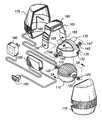
- FIGS. 1 and 1Aare an expanded perspective view of one embodiment of the preferred invention.
- FIG. 2is an expanded perspective view of inner gimbal 115 and bearing 122 .
- FIG. 3is an illustration of the optical pattern on inner module 110 , the optical pattern on gimbal frame 135 , and the elements of shaft angle encoder sensing optics 165 .
- FIG. 4is an illustration of a quad photodiode.
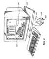
- FIG. 5is an illustration of the preferred embodiment of a gyroscopic pointing device 500 coupled to a computer and computer display 505 .
- FIG. 6is a top view of an alternative embodiment of the present invention.
- FIG. 7is a top perspective view of the embodiment of FIG. 6 .
- FIG. 8is a perspective illustrator of a directional gyroscope used to provide three-dimensional output in the embodiment of FIGS. 6 and 7 .
- FIG. 1is an expanded perspective view of one embodiment of the present invention.
- a brushless D.C. motor 105 at the core of the gyroscopespins continuously, providing the angular momentum that stabilizes the inner part of the gyroscope.
- Brushless D.C. Motors 105is a motor such as used in miniature cooling fans distributed by U.S. TOYO Fan Corporation.
- Brushless D.C. Motors 105is illustrated in the vertical cross section A—A of FIG. 1 , and is firmly mounted to inner module 110 with motor shaft 108 aligned orthogonally with respect to the axis of rotation of inner module 110 about inner gimbals 115 and 120 .
- Inner module 110consists of injection molded plastic and two conductive inner gimbals gimbal 115 and gimbal 120 .
- Inner gimbals 115 and 120are located on and aligned with the axis of rotation of inner module 110 . Further, inner gimbals 115 and 120 are electrically coupled to motor 105 .
- the center of mass of inner module 110which includes motor 105 , is slightly displaced along the axis of rotation of motor shaft 108 below the axis of rotation of inner module 110 . This results in a pendulous affect which causes motor shaft 108 to generally align with the gravity vector.
- Inner gimbals 115 and 120mechanically support inner module 110 and also provide an electrical path for the transmission of power from the gimbals to motor 105 without restricting the travel of inner module 110 .
- Two bearingssupport the inner gimbals relative to gimbal frame 135 .
- bearing 122is mounted within bearing alignment hole 125 of gimbal frame 135 and supports inner gimbal 115 .
- bearing 124is mounted within bearing alignment hole 130 of gimbal frame 135 and supports inner gimbal 120 .
- Gimbal frame 135includes two conductive outer gimbals 140 and 145 . Two bearings support the outer gimbals relative to shock frame 160 .
- bearing 146is mounted within bearing alignment hole 150 of shock frame 160 and supports outer gimbal 140 .
- bearing 147is mounted within bearing alignment hole 155 of shock frame 160 and supports outer gimbal 145 .
- Outer gimbal 140is electrically coupled to inner gimbal 115 .
- outer gimbal 145is electrically coupled to inner gimbal 120 . This completes the electrical path from the non-rotating shock frame 160 to motor 105 within inner module 110 .
- Shock frame 160is mounted with shock absorbing rubber to outer housing 175 , which consists of two halves. This shock mounting prevents damage to the bearings or optical sensors in the event that the gyroscope is dropped, and permits the inner assemblies to be constructed with finer tolerances than would be possible without the shock mounting.
- Shaft angle encoder sensing optics 165are mounted on shock frame 160 .
- Outer housing 175is opaque so as to prevent outside light from interfering with the optical sensing system and is adapted for hand holding as described more fully below with reference to FIGS. 5 and 6 .
- Cabling 180transmits power from an interlace interface box 185 to outer housing 175 and returns data signals from shaft angle encoder sensing optics 165 .
- interface box 185translates signals from the optical sensing system 165 into serial data for an RS-232 port.
- Wall adapter 190provides D.C. power for motor 105 and shalt shaft angle encoder sensing optics 165 .
- FIG. 2is an expanded perspective view of inner gimbal 115 and bearing 122 .
- Inner gimbal 115includes a circular plug 205 which fits within the inner race of bearing 122 .
- a conductive pin 210having a diameter smaller than that of plug 205 , is mounted concentrically with plug 205 and electrically coupled to motor 205 .
- Pin 210is preferably made of a low-friction conductive material such as carbon-teflon and designed to protrude from the inner race of bearing 122 .
- the diameter of pin 210is smaller than the diameter of the inner race so as not to contact the inner race and to minimize the friction of the rotating contact.
- a stainless steel spring 215is mounted to gimbal frame 135 and aligned with and in electrical contact with protruding surface 220 of pin 210 .
- Spring 215is electrically coupled to a D.C. power source through outer gimbal 140 .
- Spring 215presses against pin 210 providing a low friction electrical connection between gimbal frame 135 and inner module 110 .
- Inner gimbal 120 and outer gimbals 140 and 145are constructed in an identical manner.
- Inner module 110has a hemispherical outer surface with an optical pattern which interacts with shaft angle encoder sensing optics 165 to sense the rotation of inner module 110 around the axis of rotation through gimbals 115 and 120 .
- This optical patternis illustrated in FIG. 3 .
- the optical pattern on inner module 110is constructed by first painting the hemispherical surface with a highly reflective aluminum flaked paint and then machining grooves of 0.015 inch depth and width along “lines of longitude” from gimbal 115 towards gimbal 120 along the surface. The grooves are machined to within 30 degrees of each inner gimbal and are 0.015 inches apart at 30 degrees from each gimbal.
- Inner module 110is molded from a non-reflective black plastic. Thus the grooved portions of inner module 110 . where the reflective paint has been machined off, are non-reflective. This provides a precise optical pattern on inner module 110 having a relatively high contrast ratio.
- AndA second optical patternis machined into gimbal frame 135 along a cylindrical section 170 of gimbal frame 135 .
- This patterninteracts with shaltshaft angle encoder sensing optics 165 for sensing rotation of gimbal frame 135 around its axis of rotation through gimbals 140 and 145 .
- This cylindrical sectionis geometrically centered about the axis of rotation of gimbal frame 135 , which passes through gimbals 140 and 145 .
- the optical pattern on gimbal frame 135is constructed by applying reflective paint to cylindrical section 170 and then machining grooves of 0.015 inch depth and width on the surface of the cylinder.
- Cylindrical section 170is displaced slightly from the center of gimbal frame 135 so as not lo interfere with the interaction of shaft angle encoder sensing optics 165 and the optical pattern on inner module 110 . Specifically, the closest edge of cylindrical section 170 is spaced approximately 0.15 inches away from the “equator” of frame 170 passing through inner gimbals 115 and 120 .
- Shaft angle encoder sensing optics 165interact with the optical pattern on inner module 110 so as to determine the rotation of the inner module 110 about its axis of rotation. More specifically, shaft angle encoder sensing optic 165 include sources for illuminating the patterns, lenses for focusing images of the patterns, and photodetectors for detect a detecting dark or light areas.
- a first LED 305is mounted to shock frame 160 at an angle of 30 degrees from vertical in a plane parallel to the axis through gimbals 140 and 145 so as to floodlight an area 310 of the optical pattern on inner module 110 . This area is centered on the “equator” of frame 135 so as to provide maximum range of detectable movement in both directions.
- Lens 315 and mirror 320focus and reflect the image of the illuminated optical pattern onto quad photodiode 325 .
- Lens 315is an injection molded lens of approximately 1 ⁇ 8 inch in diameter having a focal length of approximately 0.2 inches.
- Quad photodiode 325comprises four photodiodes, 402 , 404 , 406 and 408 , located in a row as illustrated in FIG. 4 .
- the sides of quad photodiode 325are aligned with the edges of the projected image of the optical pattern on inner module 110 .
- One period of the projected image of the optical pattern on inner module 110(one light and one dark bar) nominally covers the quad photodiode 325 , which comprise four photodiodes centered 0.02 inches apart.
- Photodiodes 402 and 406are counted coupled to comparator 420 410 .
- Photodiodes 404 and 408are coupled to comparator 410 420 .
- phase quadrature resolutionis provided in U.S. Pat. No. 4,346,989 titled Surveying Instrument, issued to Alfred F. Gori Gort and Charles E. Moore Aug. 31, 1982 and assigned to the Hewlett-Packard Company. A prototype of this embodiment of the present invention results in a resolution of approximately 100 counts per inch.
- Shaft angle encoder sensing optics 165also interacts with the optical pattern on gimbal frame 160 so as to determine the rotation of gimbal frame 135 about its axis of rotation. More specfically, a second sensing system, similar to the one described but oriented 90 degrees with respect to the first, is positioned on frame 160 so as to interact with the optical pattern on frame 135 and to detect rotation of frame 135 about its axis of rotation. Referring again to FIG. 3 , a second LED 330 is mounted to shock frame 160 at an angle of 30 degrees from vertical in a plane parallel to the axis through gimbals 115 and 120 in alignment with cylindrical section 170 so as to floodlight an area 335 of the optical pattern on cylindrical section 170 . Lens 340 and mirror 320 focus and reflect the image of the illuminated optical pattern onto quad photodiode 345 . Lens 340 is an injection molded lens of approximately 1 ⁇ 8 inch in diameter having a focal length of approximately 0.2 inches.
- Quad photodiode 345comprises four photodiodes located in a row and is identical in construction to quad photodiode 325 illustrated in FIG. 4 .
- the sides of quad photodiode 345are aligned with the edges of the projected image of the optical pattern on gimbal frame 135 .
- FIG. 5is an illustration of the preferred embodiment of a gyroscopic pointing device 500 coupled to a computer 502 and computer display 505 .
- Computer 502is adapted so that changing the pitch of controller 500 relative to the gravity vector charges changes the vertical position of cursor 510 on computer display 505 .
- rotating the controller forwardcauses the cursor to drop on a vertical computer screen
- rotating it backcauses the cursor to drop on a vertical computer screen
- rotating it backcauses the cursor to rise, as if the controller was pointing at the cursor.
- rotating the controller from side to sidechanges the horizontal position of cursor 510 on computer display 505 . That is, rotating the controller left causes the cursor to move left on a vertical computer screen, rotating it right causes the cursor to move to the right, again, as it if the controller was pointing at the cursor.
- Controller 500further includes a thumb operated push button 520 and has a rounded hemispherically shaped bottom portion 525 adapted for smoothly rocking on a flat surface when the pitch and roll of controller 500 is varied while resting on a flat surface.
- Thiscan be a two position switch, where initial pressure on the switch activates the controller and causes the cursor to move in response to the controller, and a second position of the switch results in a “pick” or “select” signal being transmitted to the computer.
- FIG. 6is a top view of an alternative embodiment of the present invention.
- FIG. 7is a top perspective view of the same embodiment.
- FIGS. 6 and 7illustrate a controller shaped so as to be hand held in a manner such that the palm will be facing down while controller 610 is resting on a flat surface. The under side of controller 610 is rounded to facilitate changes of its orientation with respect to vertical.
- a palm button 620is actuated when the controller is grasped, thus permitting the controller to be deactivated, moved or reoriented, then reactivated.
- a pick button 630is located for selective activation by a users lingersuser's fingers in a manner similar to the use of a pick button on a mouse controller.
- FIGS. 6 and 7includes a first gyroscope as discussed with regards to FIGS. 1-4 for the measurement of pitch and roll. Further, it includes a second gyroscope, as illustrated in FIG. 8 , for measurement of yaw about the vertical axis.
- a rotating gyroscopic element 810is mounted in a two-degree-of freedom gimbal system with its spin axis 820 in a horizontal direction.
- a massgives the gyroscope a pendulosity at right angles to spin axis 820 .
- gyroscope 810is mounted to inner frame 815 .
- Inner frame 815is mounted to gimbal frame 825 by inner gimbals 845 .
- Gimbal frame 825is mounted to an outer housing 860 by gimbal 850 .
- a shaft angle encoder 870is coupled to detect the rotation of gimbal frame 825 relative to outer housing 860 . Oscillations are damped out by applying an antipendulous torque caused by liquid flow of a viscous fluid through a constriction in a tube, as in damper 840 .
- Computer 502is further adapted to convert the angle measured by shaft angle encoder 870 . This conversion could be to rotation of the cursor or a cursor-selected object or for providing a “z” input for a three dimensional display or a two-dimensional display simulating a three dimensional view.
Landscapes
- Engineering & Computer Science (AREA)
- General Engineering & Computer Science (AREA)
- Theoretical Computer Science (AREA)
- Human Computer Interaction (AREA)
- Physics & Mathematics (AREA)
- General Physics & Mathematics (AREA)
- Position Input By Displaying (AREA)
Abstract
Description
Claims (47)
Priority Applications (1)
| Application Number | Priority Date | Filing Date | Title |
|---|---|---|---|
| US09/642,250USRE41520E1 (en) | 1990-03-21 | 2000-10-12 | Gyroscopic pointer and method |
Applications Claiming Priority (5)
| Application Number | Priority Date | Filing Date | Title |
|---|---|---|---|
| US49712790A | 1990-03-21 | 1990-03-21 | |
| US08/000,651US5440326A (en) | 1990-03-21 | 1993-01-05 | Gyroscopic pointer |
| US40672795A | 1995-03-20 | 1995-03-20 | |
| US08/643,991US5898421A (en) | 1990-03-21 | 1996-05-07 | Gyroscopic pointer and method |
| US09/642,250USRE41520E1 (en) | 1990-03-21 | 2000-10-12 | Gyroscopic pointer and method |
Related Parent Applications (1)
| Application Number | Title | Priority Date | Filing Date |
|---|---|---|---|
| US08/643,991ReissueUS5898421A (en) | 1990-03-21 | 1996-05-07 | Gyroscopic pointer and method |
Publications (1)
| Publication Number | Publication Date |
|---|---|
| USRE41520E1true USRE41520E1 (en) | 2010-08-17 |
Family
ID=23975579
Family Applications (3)
| Application Number | Title | Priority Date | Filing Date |
|---|---|---|---|
| US08/000,651Expired - LifetimeUS5440326A (en) | 1990-03-21 | 1993-01-05 | Gyroscopic pointer |
| US08/643,991Expired - LifetimeUS5898421A (en) | 1990-03-21 | 1996-05-07 | Gyroscopic pointer and method |
| US09/642,250Expired - LifetimeUSRE41520E1 (en) | 1990-03-21 | 2000-10-12 | Gyroscopic pointer and method |
Family Applications Before (2)
| Application Number | Title | Priority Date | Filing Date |
|---|---|---|---|
| US08/000,651Expired - LifetimeUS5440326A (en) | 1990-03-21 | 1993-01-05 | Gyroscopic pointer |
| US08/643,991Expired - LifetimeUS5898421A (en) | 1990-03-21 | 1996-05-07 | Gyroscopic pointer and method |
Country Status (1)
| Country | Link |
|---|---|
| US (3) | US5440326A (en) |
Cited By (1)
| Publication number | Priority date | Publication date | Assignee | Title |
|---|---|---|---|---|
| CN103443756A (en)* | 2011-03-09 | 2013-12-11 | 国誉株式会社 | Display system |
Families Citing this family (445)
| Publication number | Priority date | Publication date | Assignee | Title |
|---|---|---|---|---|
| JPH07302157A (en)* | 1994-04-28 | 1995-11-14 | Nintendo Co Ltd | Operation device |
| SE503067C2 (en)* | 1994-07-06 | 1996-03-18 | Rolf Blomdahl | Controllers for computers or industrial processes |
| US5796387A (en)* | 1994-08-16 | 1998-08-18 | Smith Engineering | Positioning system using infrared radiation |
| WO1996025702A2 (en)* | 1995-02-13 | 1996-08-22 | Philips Electronics N.V. | A portable data processing apparatus provided with a screen and a gravitation-controlled sensor for screen orientation |
| USD378751S (en)* | 1995-10-19 | 1997-04-08 | Gyration, Inc. | Graphic display controller |
| US6081261A (en)* | 1995-11-01 | 2000-06-27 | Ricoh Corporation | Manual entry interactive paper and electronic document handling and processing system |
| US5902968A (en)* | 1996-02-20 | 1999-05-11 | Ricoh Company, Ltd. | Pen-shaped handwriting input apparatus using accelerometers and gyroscopes and an associated operational device for determining pen movement |
| JPH1049290A (en)* | 1996-08-05 | 1998-02-20 | Sony Corp | Device and method for processing information |
| US5764164A (en)* | 1997-02-07 | 1998-06-09 | Reality Quest Corp. | Ergonomic hand-attachable controller |
| US5796354A (en)* | 1997-02-07 | 1998-08-18 | Reality Quest Corp. | Hand-attachable controller with direction sensing |
| US6104380A (en)* | 1997-04-14 | 2000-08-15 | Ricoh Company, Ltd. | Direct pointing apparatus for digital displays |
| US7247021B2 (en)* | 1997-06-20 | 2007-07-24 | Align Technology, Inc. | Subdividing a digital dentition model |
| US8496474B2 (en)* | 1997-06-20 | 2013-07-30 | Align Technology, Inc. | Computer automated development of an orthodontic treatment plan and appliance |
| US5975893A (en)* | 1997-06-20 | 1999-11-02 | Align Technology, Inc. | Method and system for incrementally moving teeth |
| US6705863B2 (en)* | 1997-06-20 | 2004-03-16 | Align Technology, Inc. | Attachment devices and methods for a dental appliance |
| US6450807B1 (en) | 1997-06-20 | 2002-09-17 | Align Technology, Inc. | System and method for positioning teeth |
| US6409504B1 (en)* | 1997-06-20 | 2002-06-25 | Align Technology, Inc. | Manipulating a digital dentition model to form models of individual dentition components |
| US6188392B1 (en) | 1997-06-30 | 2001-02-13 | Intel Corporation | Electronic pen device |
| WO1999003060A1 (en) | 1997-07-08 | 1999-01-21 | Koninklijke Philips Electronics N.V. | Input device |
| US6075518A (en)* | 1997-07-15 | 2000-06-13 | Gateway 2000, Inc. | Rotational X-axis pointing device |
| US6201903B1 (en) | 1997-09-30 | 2001-03-13 | Ricoh Company, Ltd. | Method and apparatus for pen-based faxing |
| AU1521799A (en)* | 1997-11-10 | 1999-05-31 | Sc&T International, Inc. | An input apparatus for a computer or game |
| US6181329B1 (en) | 1997-12-23 | 2001-01-30 | Ricoh Company, Ltd. | Method and apparatus for tracking a hand-held writing instrument with multiple sensors that are calibrated by placing the writing instrument in predetermined positions with respect to the writing surface |
| IL122807A0 (en) | 1997-12-30 | 1998-08-16 | Cadent Ltd | Virtual orthodontic treatment |
| US20040090423A1 (en)* | 1998-02-27 | 2004-05-13 | Logitech Europe S.A. | Remote controlled video display GUI using 2-directional pointing |
| DE19819218A1 (en)* | 1998-04-29 | 1999-07-22 | Siemens Ag | Actuation element especially joystick for computer |
| IL125659A (en) | 1998-08-05 | 2002-09-12 | Cadent Ltd | Method and apparatus for imaging three-dimensional structure |
| WO2000017849A1 (en)* | 1998-09-18 | 2000-03-30 | Kim Tong | Head operated computer pointer |
| US6227850B1 (en) | 1999-05-13 | 2001-05-08 | Align Technology, Inc. | Teeth viewing system |
| CA2346299A1 (en)* | 1998-10-08 | 2000-04-13 | Align Technology, Inc. | Computer automated development of an orthodontic treatment plan and appliance |
| US6802713B1 (en) | 1998-10-08 | 2004-10-12 | Align Technology, Inc. | Defining tooth-moving appliances computationally |
| US11026768B2 (en)* | 1998-10-08 | 2021-06-08 | Align Technology, Inc. | Dental appliance reinforcement |
| US6504526B1 (en)* | 1998-11-03 | 2003-01-07 | Intel Corporation | Wireless pointing system |
| US6406292B1 (en) | 1999-05-13 | 2002-06-18 | Align Technology, Inc. | System for determining final position of teeth |
| AU2164100A (en) | 1998-12-04 | 2000-06-26 | Align Technology, Inc. | Reconfigurable dental model system for fabrication of dental appliances |
| US6664946B1 (en)* | 1999-02-22 | 2003-12-16 | Microsoft Corporation | Dual axis articulated computer input device and method of operation |
| US7749089B1 (en) | 1999-02-26 | 2010-07-06 | Creative Kingdoms, Llc | Multi-media interactive play system |
| JP2000315132A (en) | 1999-04-30 | 2000-11-14 | Sony Corp | Device and method for information processing and medium |
| DE19926596A1 (en)* | 1999-06-11 | 2000-12-14 | Bosch Gmbh Robert | Control element |
| US7122004B1 (en)* | 1999-08-13 | 2006-10-17 | Interactive Metronome, Inc. | Method and apparatus of enhancing learning capacity |
| US6375572B1 (en) | 1999-10-04 | 2002-04-23 | Nintendo Co., Ltd. | Portable game apparatus with acceleration sensor and information storage medium storing a game progam |
| JP3847058B2 (en)* | 1999-10-04 | 2006-11-15 | 任天堂株式会社 | GAME SYSTEM AND GAME INFORMATION STORAGE MEDIUM USED FOR THE SAME |
| US6463344B1 (en) | 2000-02-17 | 2002-10-08 | Align Technology, Inc. | Efficient data representation of teeth model |
| US7373286B2 (en) | 2000-02-17 | 2008-05-13 | Align Technology, Inc. | Efficient data representation of teeth model |
| US6633789B1 (en) | 2000-02-17 | 2003-10-14 | Align Technology, Inc. | Effiicient data representation of teeth model |
| US7445550B2 (en) | 2000-02-22 | 2008-11-04 | Creative Kingdoms, Llc | Magical wand and interactive play experience |
| US6761637B2 (en) | 2000-02-22 | 2004-07-13 | Creative Kingdoms, Llc | Method of game play using RFID tracking device |
| US7878905B2 (en) | 2000-02-22 | 2011-02-01 | Creative Kingdoms, Llc | Multi-layered interactive play experience |
| US7904307B2 (en) | 2000-03-24 | 2011-03-08 | Align Technology, Inc. | Health-care e-commerce systems and methods |
| US20020188478A1 (en)* | 2000-03-24 | 2002-12-12 | Joe Breeland | Health-care systems and methods |
| US6454565B2 (en) | 2000-04-25 | 2002-09-24 | Align Technology, Inc. | Systems and methods for varying elastic modulus appliances |
| WO2001082192A1 (en) | 2000-04-25 | 2001-11-01 | Align Technology, Inc. | Treatment analysis systems and methods |
| US7245977B1 (en) | 2000-07-20 | 2007-07-17 | Align Technology, Inc. | Systems and methods for mass customization |
| US7383198B1 (en) | 2000-07-24 | 2008-06-03 | Align Technology, Inc. | Delivery information systems and methods |
| US7040896B2 (en) | 2000-08-16 | 2006-05-09 | Align Technology, Inc. | Systems and methods for removing gingiva from computer tooth models |
| EP1316189A2 (en)* | 2000-09-01 | 2003-06-04 | Max Mühlhäuser | System and method for the wireless access of computer-based services in an attributable manner |
| US6529144B1 (en)* | 2000-09-22 | 2003-03-04 | Motorola Inc. | Method and apparatus for motion activated control of an electronic device |
| US7066781B2 (en)* | 2000-10-20 | 2006-06-27 | Denise Chapman Weston | Children's toy with wireless tag/transponder |
| US7736147B2 (en) | 2000-10-30 | 2010-06-15 | Align Technology, Inc. | Systems and methods for bite-setting teeth models |
| US20020085097A1 (en)* | 2000-12-22 | 2002-07-04 | Colmenarez Antonio J. | Computer vision-based wireless pointing system |
| US7074038B1 (en) | 2000-12-29 | 2006-07-11 | Align Technology, Inc. | Methods and systems for treating teeth |
| US7580846B2 (en) | 2001-01-09 | 2009-08-25 | Align Technology, Inc. | Method and system for distributing patient referrals |
| US20100156783A1 (en)* | 2001-07-06 | 2010-06-24 | Bajramovic Mark | Wearable data input device |
| US7771195B2 (en)* | 2001-10-29 | 2010-08-10 | Align Technology, Inc. | Polar attachment devices and method for a dental appliance |
| US20030107551A1 (en)* | 2001-12-10 | 2003-06-12 | Dunker Garrett Storm | Tilt input device |
| US6967566B2 (en) | 2002-04-05 | 2005-11-22 | Creative Kingdoms, Llc | Live-action interactive adventure game |
| US20070066396A1 (en) | 2002-04-05 | 2007-03-22 | Denise Chapman Weston | Retail methods for providing an interactive product to a consumer |
| US7474296B2 (en) | 2002-04-12 | 2009-01-06 | Obermeyer Henry K | Multi-axis joystick and transducer means therefore |
| US7079452B2 (en)* | 2002-04-16 | 2006-07-18 | Harrison Shelton E | Time display system, method and device |
| US6830450B2 (en) | 2002-04-18 | 2004-12-14 | Align Technology, Inc. | Systems and methods for improved engagement between aligners and teeth |
| US6954198B2 (en)* | 2002-05-02 | 2005-10-11 | Hung-Ying Shih | Ergonomically shaped computer pointing device |
| JP2003325972A (en) | 2002-05-17 | 2003-11-18 | Nintendo Co Ltd | Game device changing sound and image in association with tilt operation, and game program therefor |
| US7255558B2 (en) | 2002-06-18 | 2007-08-14 | Cadent, Ltd. | Dental imaging instrument having air stream auxiliary |
| US8797260B2 (en) | 2002-07-27 | 2014-08-05 | Sony Computer Entertainment Inc. | Inertially trackable hand-held controller |
| US8686939B2 (en) | 2002-07-27 | 2014-04-01 | Sony Computer Entertainment Inc. | System, method, and apparatus for three-dimensional input control |
| US8570378B2 (en)* | 2002-07-27 | 2013-10-29 | Sony Computer Entertainment Inc. | Method and apparatus for tracking three-dimensional movements of an object using a depth sensing camera |
| US10086282B2 (en)* | 2002-07-27 | 2018-10-02 | Sony Interactive Entertainment Inc. | Tracking device for use in obtaining information for controlling game program execution |
| US7782297B2 (en) | 2002-07-27 | 2010-08-24 | Sony Computer Entertainment America Inc. | Method and apparatus for use in determining an activity level of a user in relation to a system |
| US8019121B2 (en)* | 2002-07-27 | 2011-09-13 | Sony Computer Entertainment Inc. | Method and system for processing intensity from input devices for interfacing with a computer program |
| US8313380B2 (en) | 2002-07-27 | 2012-11-20 | Sony Computer Entertainment America Llc | Scheme for translating movements of a hand-held controller into inputs for a system |
| US9393487B2 (en)* | 2002-07-27 | 2016-07-19 | Sony Interactive Entertainment Inc. | Method for mapping movements of a hand-held controller to game commands |
| US20060256081A1 (en)* | 2002-07-27 | 2006-11-16 | Sony Computer Entertainment America Inc. | Scheme for detecting and tracking user manipulation of a game controller body |
| US20060264260A1 (en)* | 2002-07-27 | 2006-11-23 | Sony Computer Entertainment Inc. | Detectable and trackable hand-held controller |
| US20060282873A1 (en)* | 2002-07-27 | 2006-12-14 | Sony Computer Entertainment Inc. | Hand-held controller having detectable elements for tracking purposes |
| US7674184B2 (en) | 2002-08-01 | 2010-03-09 | Creative Kingdoms, Llc | Interactive water attraction and quest game |
| US20040243361A1 (en)* | 2002-08-19 | 2004-12-02 | Align Technology, Inc. | Systems and methods for providing mass customization |
| US7156661B2 (en)* | 2002-08-22 | 2007-01-02 | Align Technology, Inc. | Systems and methods for treatment analysis by teeth matching |
| US7077647B2 (en)* | 2002-08-22 | 2006-07-18 | Align Technology, Inc. | Systems and methods for treatment analysis by teeth matching |
| US6834561B2 (en)* | 2002-08-22 | 2004-12-28 | Honeywell International Inc. | Radially actuated control moment gyroscope |
| US20040197728A1 (en)* | 2002-09-10 | 2004-10-07 | Amir Abolfathi | Architecture for treating teeth |
| US20040152036A1 (en)* | 2002-09-10 | 2004-08-05 | Amir Abolfathi | Architecture for treating teeth |
| EP3403612B1 (en) | 2002-10-03 | 2023-06-07 | Align Technology, Inc. | A method for preparing a teeth model |
| US7030856B2 (en)* | 2002-10-15 | 2006-04-18 | Sony Corporation | Method and system for controlling a display device |
| US20040155865A1 (en)* | 2002-12-16 | 2004-08-12 | Swiader Michael C | Ergonomic data input and cursor control device |
| US20050032582A1 (en)* | 2002-12-19 | 2005-02-10 | Satayan Mahajan | Method and apparatus for determining orientation and position of a moveable object |
| US7658610B2 (en)* | 2003-02-26 | 2010-02-09 | Align Technology, Inc. | Systems and methods for fabricating a dental template with a 3-D object placement |
| US7600999B2 (en)* | 2003-02-26 | 2009-10-13 | Align Technology, Inc. | Systems and methods for fabricating a dental template |
| US20040166462A1 (en) | 2003-02-26 | 2004-08-26 | Align Technology, Inc. | Systems and methods for fabricating a dental template |
| US7034283B2 (en)* | 2003-03-05 | 2006-04-25 | Raytheon Company | Absolute incremental position encoder and method |
| US9446319B2 (en) | 2003-03-25 | 2016-09-20 | Mq Gaming, Llc | Interactive gaming toy |
| WO2004087000A1 (en) | 2003-04-03 | 2004-10-14 | Cadent Ltd. | Method and system for fabricating a dental coping, and a coping fabricated thereby |
| US20040212589A1 (en)* | 2003-04-24 | 2004-10-28 | Hall Deirdre M. | System and method for fusing and displaying multiple degree of freedom positional input data from multiple input sources |
| US7081884B2 (en)* | 2003-04-25 | 2006-07-25 | Microsoft Corporation | Computer input device with angular displacement detection capabilities |
| US7233316B2 (en) | 2003-05-01 | 2007-06-19 | Thomson Licensing | Multimedia user interface |
| US7480001B2 (en)* | 2003-07-02 | 2009-01-20 | Sony Corporation | Digital camera with a spherical display |
| US20050001920A1 (en)* | 2003-07-02 | 2005-01-06 | Endler Sean Christopher | Methods and apparatuses for managing and presenting content through a spherical display device |
| US7030383B2 (en) | 2003-08-04 | 2006-04-18 | Cadent Ltd. | Speckle reduction method and apparatus |
| US7489299B2 (en)* | 2003-10-23 | 2009-02-10 | Hillcrest Laboratories, Inc. | User interface devices and methods employing accelerometers |
| US7361020B2 (en)* | 2003-11-19 | 2008-04-22 | Align Technology, Inc. | Dental tray containing radiopaque materials |
| US20060025229A1 (en)* | 2003-12-19 | 2006-02-02 | Satayan Mahajan | Motion tracking and analysis apparatus and method and system implementations thereof |
| US20050182654A1 (en)* | 2004-02-14 | 2005-08-18 | Align Technology, Inc. | Systems and methods for providing treatment planning |
| US7096619B2 (en)* | 2004-02-17 | 2006-08-29 | Jackson Charles L | Equipment operator personalization device |
| US7333874B2 (en) | 2004-02-24 | 2008-02-19 | Cadent Ltd. | Method and system for designing and producing dental prostheses and appliances |
| US20050186524A1 (en)* | 2004-02-24 | 2005-08-25 | Align Technology, Inc. | Arch expander |
| US7904308B2 (en) | 2006-04-18 | 2011-03-08 | Align Technology, Inc. | Method and system for providing indexing and cataloguing of orthodontic related treatment profiles and options |
| US9492245B2 (en) | 2004-02-27 | 2016-11-15 | Align Technology, Inc. | Method and system for providing dynamic orthodontic assessment and treatment profiles |
| US8874452B2 (en) | 2004-02-27 | 2014-10-28 | Align Technology, Inc. | Method and system for providing dynamic orthodontic assessment and treatment profiles |
| US11298209B2 (en) | 2004-02-27 | 2022-04-12 | Align Technology, Inc. | Method and system for providing dynamic orthodontic assessment and treatment profiles |
| US7241142B2 (en)* | 2004-03-19 | 2007-07-10 | Align Technology, Inc. | Root-based tooth moving sequencing |
| US7625316B1 (en) | 2004-04-27 | 2009-12-01 | Performance Health Technologies, Inc. | Position monitoring system |
| US7503878B1 (en) | 2004-04-27 | 2009-03-17 | Performance Health Technologies, Inc. | Position monitoring device |
| US7658695B1 (en) | 2004-04-27 | 2010-02-09 | Performance Health Technologies, Inc. | Position monitoring displays |
| EP1759529A4 (en)* | 2004-04-30 | 2009-11-11 | Hillcrest Lab Inc | FREE SPACE POINTING DEVICE AND ASSOCIATED METHODS |
| US7236156B2 (en) | 2004-04-30 | 2007-06-26 | Hillcrest Laboratories, Inc. | Methods and devices for identifying users based on tremor |
| CN100440313C (en)* | 2004-04-30 | 2008-12-03 | 希尔克瑞斯特实验室公司 | Free space positioning device and free space positioning method |
| JP2007535774A (en)* | 2004-04-30 | 2007-12-06 | ヒルクレスト・ラボラトリーズ・インコーポレイテッド | Method and device for removing unintentional movement in a free space pointing device |
| US7158118B2 (en)* | 2004-04-30 | 2007-01-02 | Hillcrest Laboratories, Inc. | 3D pointing devices with orientation compensation and improved usability |
| US8629836B2 (en) | 2004-04-30 | 2014-01-14 | Hillcrest Laboratories, Inc. | 3D pointing devices with orientation compensation and improved usability |
| US7746321B2 (en) | 2004-05-28 | 2010-06-29 | Erik Jan Banning | Easily deployable interactive direct-pointing system and presentation control system and calibration method therefor |
| US7698068B2 (en) | 2004-06-17 | 2010-04-13 | Cadent Ltd. | Method for providing data associated with the intraoral cavity |
| US20050285948A1 (en)* | 2004-06-22 | 2005-12-29 | Harvey Weinberg | System and method for processing a digital camera image |
| USD541805S1 (en) | 2004-06-30 | 2007-05-01 | Swiader Michael C | Data input and cursor control device |
| US7542072B2 (en)* | 2004-07-28 | 2009-06-02 | The University Of Maryland | Device using a camera and light polarization for the remote displacement of a cursor on a display |
| US20060024647A1 (en)* | 2004-07-30 | 2006-02-02 | France Telecom | Method and apparatus for communicating graphical information to a visually impaired person using haptic feedback |
| MX2007002011A (en)* | 2004-08-23 | 2007-08-07 | Gamecaster Inc | Apparatus, methods and systems for viewing and manipulating a virtual environment. |
| USD550633S1 (en) | 2004-08-23 | 2007-09-11 | Hillcrest Laboratories, Inc. | Remote control |
| JP2006068027A (en)* | 2004-08-31 | 2006-03-16 | Nintendo Co Ltd | Game device and game program |
| US7683883B2 (en)* | 2004-11-02 | 2010-03-23 | Pierre Touma | 3D mouse and game controller based on spherical coordinates system and system for use |
| US9317108B2 (en) | 2004-11-02 | 2016-04-19 | Pierre A. Touma | Hand-held wireless electronic device with accelerometer for interacting with a display |
| US9900669B2 (en) | 2004-11-02 | 2018-02-20 | Pierre Touma | Wireless motion sensor system and method |
| US7309230B2 (en) | 2004-12-14 | 2007-12-18 | Align Technology, Inc. | Preventing interference between tooth models |
| US7357634B2 (en)* | 2004-11-05 | 2008-04-15 | Align Technology, Inc. | Systems and methods for substituting virtual dental appliances |
| US8137195B2 (en) | 2004-11-23 | 2012-03-20 | Hillcrest Laboratories, Inc. | Semantic gaming and application transformation |
| US7862336B2 (en) | 2004-11-26 | 2011-01-04 | Cadent Ltd. | Method and system for providing feedback data useful in prosthodontic procedures associated with the intra oral cavity |
| US7236842B2 (en) | 2004-12-02 | 2007-06-26 | Cadent Ltd. | System and method for manufacturing a dental prosthesis and a dental prosthesis manufactured thereby |
| WO2006083563A2 (en)* | 2005-02-01 | 2006-08-10 | Analog Devices, Inc. | Camera with acceleration sensor |
| CN100347648C (en)* | 2005-02-02 | 2007-11-07 | 陈其良 | Azimuth type computer inputting device |
| EP1869403B1 (en) | 2005-03-03 | 2017-06-14 | Align Technology, Inc. | System and method for scanning an intraoral cavity |
| US7492367B2 (en)* | 2005-03-10 | 2009-02-17 | Motus Corporation | Apparatus, system and method for interpreting and reproducing physical motion |
| US20060275731A1 (en) | 2005-04-29 | 2006-12-07 | Orthoclear Holdings, Inc. | Treatment of teeth by aligners |
| US7821494B2 (en)* | 2005-05-13 | 2010-10-26 | Industrial Technology Research Institute | Inertial mouse |
| JP2009500923A (en)* | 2005-07-01 | 2009-01-08 | ヒルクレスト・ラボラトリーズ・インコーポレイテッド | 3D pointing device |
| US9285897B2 (en) | 2005-07-13 | 2016-03-15 | Ultimate Pointer, L.L.C. | Easily deployable interactive direct-pointing system and calibration method therefor |
| US7555403B2 (en) | 2005-07-15 | 2009-06-30 | Cadent Ltd. | Method for manipulating a dental virtual model, method for creating physical entities based on a dental virtual model thus manipulated, and dental models thus created |
| JP4805633B2 (en) | 2005-08-22 | 2011-11-02 | 任天堂株式会社 | Game operation device |
| US7942745B2 (en) | 2005-08-22 | 2011-05-17 | Nintendo Co., Ltd. | Game operating device |
| US7927216B2 (en) | 2005-09-15 | 2011-04-19 | Nintendo Co., Ltd. | Video game system with wireless modular handheld controller |
| US8313379B2 (en) | 2005-08-22 | 2012-11-20 | Nintendo Co., Ltd. | Video game system with wireless modular handheld controller |
| JP4262726B2 (en) | 2005-08-24 | 2009-05-13 | 任天堂株式会社 | Game controller and game system |
| US8870655B2 (en) | 2005-08-24 | 2014-10-28 | Nintendo Co., Ltd. | Wireless game controllers |
| US8308563B2 (en) | 2005-08-30 | 2012-11-13 | Nintendo Co., Ltd. | Game system and storage medium having game program stored thereon |
| US8157651B2 (en) | 2005-09-12 | 2012-04-17 | Nintendo Co., Ltd. | Information processing program |
| JP4471910B2 (en)* | 2005-09-14 | 2010-06-02 | 任天堂株式会社 | Virtual positioning program |
| EP1775656A1 (en) | 2005-10-12 | 2007-04-18 | Industrial Technology Research Institute | Inertial sensing input apparatus |
| US20070113207A1 (en)* | 2005-11-16 | 2007-05-17 | Hillcrest Laboratories, Inc. | Methods and systems for gesture classification in 3D pointing devices |
| US20070109324A1 (en)* | 2005-11-16 | 2007-05-17 | Qian Lin | Interactive viewing of video |
| TWI296202B (en)* | 2005-12-01 | 2008-05-01 | Ind Tech Res Inst | Input device and method for shooting games |
| TWI316195B (en)* | 2005-12-01 | 2009-10-21 | Ind Tech Res Inst | Input means for interactive devices |
| US20090046140A1 (en)* | 2005-12-06 | 2009-02-19 | Microvision, Inc. | Mobile Virtual Reality Projector |
| US20110111849A1 (en)* | 2005-12-06 | 2011-05-12 | Microvision, Inc. | Spatially Aware Mobile Projection |
| WO2007067720A2 (en)* | 2005-12-06 | 2007-06-14 | Microvision, Inc. | Projection display with motion compensation |
| US20070282564A1 (en)* | 2005-12-06 | 2007-12-06 | Microvision, Inc. | Spatially aware mobile projection |
| MX2007015429A (en)* | 2005-12-09 | 2008-03-04 | Thomson Licensing | Inertial sensor-based pointing device with removable transceiver. |
| ES2283208B1 (en)* | 2006-01-18 | 2008-10-01 | Fundacion Fatronik | UNIDIMENSIONAL, BIDIMENSIONAL OR THREE-DIMENSIONAL EQUIPMENT CONTROL DEVICE FOR ASSISTANCE TO PERSONS WITH DISABILITIES. |
| US9411428B2 (en)* | 2006-01-31 | 2016-08-09 | Hillcrest Laboratories, Inc. | 3D pointing devices with keyboards |
| JP4530419B2 (en) | 2006-03-09 | 2010-08-25 | 任天堂株式会社 | Coordinate calculation apparatus and coordinate calculation program |
| JP4151982B2 (en)* | 2006-03-10 | 2008-09-17 | 任天堂株式会社 | Motion discrimination device and motion discrimination program |
| JP4684147B2 (en) | 2006-03-28 | 2011-05-18 | 任天堂株式会社 | Inclination calculation device, inclination calculation program, game device, and game program |
| JP4757089B2 (en)* | 2006-04-25 | 2011-08-24 | 任天堂株式会社 | Music performance program and music performance apparatus |
| JP4916762B2 (en)* | 2006-05-02 | 2012-04-18 | 任天堂株式会社 | GAME PROGRAM AND GAME DEVICE |
| US8210943B1 (en) | 2006-05-06 | 2012-07-03 | Sony Computer Entertainment America Llc | Target interface |
| US9364755B1 (en) | 2006-05-08 | 2016-06-14 | Nintendo Co., Ltd. | Methods and apparatus for using illumination marks for spatial pointing |
| JP2007304666A (en) | 2006-05-08 | 2007-11-22 | Sony Computer Entertainment Inc | Information output system and information output method |
| KR100827236B1 (en)* | 2006-05-23 | 2008-05-07 | 삼성전자주식회사 | Pointing device, pointer movement method, and display device for displaying the pointer |
| DE102006024872A1 (en)* | 2006-05-24 | 2007-11-29 | Bauhaus Universität Weimar | Portable computer input device with tactile feedback |
| US7696980B1 (en) | 2006-06-16 | 2010-04-13 | Logitech Europe S.A. | Pointing device for use in air with improved cursor control and battery life |
| US8038444B2 (en) | 2006-08-30 | 2011-10-18 | Align Technology, Inc. | Automated treatment staging for teeth |
| US8781151B2 (en)* | 2006-09-28 | 2014-07-15 | Sony Computer Entertainment Inc. | Object detection using video input combined with tilt angle information |
| USRE48417E1 (en) | 2006-09-28 | 2021-02-02 | Sony Interactive Entertainment Inc. | Object direction using video input combined with tilt angle information |
| US8310656B2 (en) | 2006-09-28 | 2012-11-13 | Sony Computer Entertainment America Llc | Mapping movements of a hand-held controller to the two-dimensional image plane of a display screen |
| US8125448B2 (en) | 2006-10-06 | 2012-02-28 | Microsoft Corporation | Wearable computer pointing device |
| US20080098448A1 (en)* | 2006-10-19 | 2008-04-24 | Sony Computer Entertainment America Inc. | Controller configured to track user's level of anxiety and other mental and physical attributes |
| US9326831B2 (en) | 2006-10-20 | 2016-05-03 | Align Technology, Inc. | System and method for positioning three-dimensional brackets on teeth |
| US20080096657A1 (en)* | 2006-10-20 | 2008-04-24 | Sony Computer Entertainment America Inc. | Method for aiming and shooting using motion sensing controller |
| US9526995B2 (en) | 2006-11-22 | 2016-12-27 | Sony Interactive Entertainment America Llc | Video game recording and playback with visual display of game controller manipulation |
| US8508472B1 (en) | 2006-11-28 | 2013-08-13 | James W. Wieder | Wearable remote control with a single control button |
| TWI319539B (en)* | 2006-11-29 | 2010-01-11 | Ind Tech Res Inst | Pointing device |
| CN100495305C (en)* | 2006-12-04 | 2009-06-03 | 财团法人工业技术研究院 | Indicating device |
| TWI317898B (en)* | 2006-12-12 | 2009-12-01 | Ind Tech Res Inst | Inertial sensing input apparatus and method |
| TWI317498B (en)* | 2006-12-12 | 2009-11-21 | Ind Tech Res Inst | Inertial input apparatus with six-axial detection ability and the opearting method thereof |
| US8250921B2 (en)* | 2007-07-06 | 2012-08-28 | Invensense, Inc. | Integrated motion processing unit (MPU) with MEMS inertial sensing and embedded digital electronics |
| US8462109B2 (en)* | 2007-01-05 | 2013-06-11 | Invensense, Inc. | Controlling and accessing content using motion processing on mobile devices |
| US20090262074A1 (en)* | 2007-01-05 | 2009-10-22 | Invensense Inc. | Controlling and accessing content using motion processing on mobile devices |
| US20100071467A1 (en)* | 2008-09-24 | 2010-03-25 | Invensense | Integrated multiaxis motion sensor |
| US8141424B2 (en)* | 2008-09-12 | 2012-03-27 | Invensense, Inc. | Low inertia frame for detecting coriolis acceleration |
| US7934423B2 (en) | 2007-12-10 | 2011-05-03 | Invensense, Inc. | Vertically integrated 3-axis MEMS angular accelerometer with integrated electronics |
| US8952832B2 (en)* | 2008-01-18 | 2015-02-10 | Invensense, Inc. | Interfacing application programs and motion sensors of a device |
| US8047075B2 (en) | 2007-06-21 | 2011-11-01 | Invensense, Inc. | Vertically integrated 3-axis MEMS accelerometer with electronics |
| US20090265671A1 (en)* | 2008-04-21 | 2009-10-22 | Invensense | Mobile devices with motion gesture recognition |
| US8508039B1 (en) | 2008-05-08 | 2013-08-13 | Invensense, Inc. | Wafer scale chip scale packaging of vertically integrated MEMS sensors with electronics |
| US8020441B2 (en)* | 2008-02-05 | 2011-09-20 | Invensense, Inc. | Dual mode sensing for vibratory gyroscope |
| US7796872B2 (en)* | 2007-01-05 | 2010-09-14 | Invensense, Inc. | Method and apparatus for producing a sharp image from a handheld device containing a gyroscope |
| JP5127242B2 (en)* | 2007-01-19 | 2013-01-23 | 任天堂株式会社 | Acceleration data processing program and game program |
| US20080188277A1 (en) | 2007-02-01 | 2008-08-07 | Ritter Janice E | Electronic Game Device And Method Of Using The Same |
| US20100184499A1 (en)* | 2007-02-01 | 2010-07-22 | Ritter Janice E | Electronic Game Device and Method of Using the Same |
| US20080215975A1 (en)* | 2007-03-01 | 2008-09-04 | Phil Harrison | Virtual world user opinion & response monitoring |
| US20080291160A1 (en)* | 2007-05-09 | 2008-11-27 | Nintendo Co., Ltd. | System and method for recognizing multi-axis gestures based on handheld controller accelerometer outputs |
| US8147333B2 (en)* | 2007-05-09 | 2012-04-03 | Nintendo Co. Ltd. | Handheld control device for a processor-controlled system |
| US8100769B2 (en)* | 2007-05-09 | 2012-01-24 | Nintendo Co., Ltd. | System and method for using accelerometer outputs to control an object rotating on a display |
| US7878805B2 (en) | 2007-05-25 | 2011-02-01 | Align Technology, Inc. | Tabbed dental appliance |
| US9060829B2 (en) | 2007-06-08 | 2015-06-23 | Align Technology, Inc. | Systems and method for management and delivery of orthodontic treatment |
| US8075306B2 (en) | 2007-06-08 | 2011-12-13 | Align Technology, Inc. | System and method for detecting deviations during the course of an orthodontic treatment to gradually reposition teeth |
| US8562338B2 (en) | 2007-06-08 | 2013-10-22 | Align Technology, Inc. | Treatment progress tracking and recalibration |
| US8591225B2 (en) | 2008-12-12 | 2013-11-26 | Align Technology, Inc. | Tooth movement measurement by automatic impression matching |
| US10342638B2 (en) | 2007-06-08 | 2019-07-09 | Align Technology, Inc. | Treatment planning and progress tracking systems and methods |
| US7860676B2 (en)* | 2007-06-28 | 2010-12-28 | Hillcrest Laboratories, Inc. | Real-time dynamic tracking of bias |
| TWI333156B (en)* | 2007-08-16 | 2010-11-11 | Ind Tech Res Inst | Inertia sensing input controller and receiver and interactive system using thereof |
| TWI334559B (en)* | 2007-08-28 | 2010-12-11 | Ind Tech Res Inst | Interactive pointing device |
| US8902227B2 (en)* | 2007-09-10 | 2014-12-02 | Sony Computer Entertainment America Llc | Selective interactive mapping of real-world objects to create interactive virtual-world objects |
| TWI391845B (en)* | 2007-09-14 | 2013-04-01 | Sony Corp | An input device, a control device, a control system, a control method, and a handheld device |
| WO2009051665A1 (en) | 2007-10-16 | 2009-04-23 | Hillcrest Laboratories, Inc. | Fast and smooth scrolling of user interfaces operating on thin clients |
| US20090115744A1 (en)* | 2007-11-06 | 2009-05-07 | Innovative Material Solutions, Inc. | Electronic freeboard writing system |
| US8738394B2 (en) | 2007-11-08 | 2014-05-27 | Eric E. Kuo | Clinical data file |
| TW200923719A (en)* | 2007-11-19 | 2009-06-01 | Asustek Comp Inc | Input apparatus and optical mouse for computer and operation method thereof |
| US7914283B2 (en) | 2007-12-06 | 2011-03-29 | Align Technology, Inc. | Activatable dental appliance |
| US9098122B2 (en)* | 2007-12-12 | 2015-08-04 | The Charles Stark Draper Laboratory, Inc. | Computer input device with inertial instruments |
| US8542907B2 (en) | 2007-12-17 | 2013-09-24 | Sony Computer Entertainment America Llc | Dynamic three-dimensional object mapping for user-defined control device |
| US8899977B2 (en) | 2008-01-29 | 2014-12-02 | Align Technology, Inc. | Orthodontic repositioning appliances having improved geometry, methods and systems |
| US8439672B2 (en) | 2008-01-29 | 2013-05-14 | Align Technology, Inc. | Method and system for optimizing dental aligner geometry |
| US9092071B2 (en) | 2008-02-13 | 2015-07-28 | Logitech Europe S.A. | Control device with an accelerometer system |
| US20090295713A1 (en)* | 2008-05-30 | 2009-12-03 | Julien Piot | Pointing device with improved cursor control in-air and allowing multiple modes of operations |
| CN102016877B (en) | 2008-02-27 | 2014-12-10 | 索尼计算机娱乐美国有限责任公司 | Method for capturing depth data of a scene and applying computer actions |
| US8108189B2 (en) | 2008-03-25 | 2012-01-31 | Align Technologies, Inc. | Reconstruction of non-visible part of tooth |
| WO2009145854A1 (en)* | 2008-04-15 | 2009-12-03 | Hillcrest Laboratories, Inc. | Tracking determination based on intensity angular gradient of a wave |
| US8092215B2 (en) | 2008-05-23 | 2012-01-10 | Align Technology, Inc. | Smile designer |
| US9119691B2 (en) | 2008-05-23 | 2015-09-01 | Align Technology, Inc. | Orthodontic tooth movement device, systems and methods |
| US9492243B2 (en) | 2008-05-23 | 2016-11-15 | Align Technology, Inc. | Dental implant positioning |
| CN101593050B (en)* | 2008-05-30 | 2014-04-16 | 鸿富锦精密工业(深圳)有限公司 | Control device and control method of electronic equipment |
| US8172569B2 (en) | 2008-06-12 | 2012-05-08 | Align Technology, Inc. | Dental appliance |
| FR2933212B1 (en) | 2008-06-27 | 2013-07-05 | Movea Sa | MOVING CAPTURE POINTER RESOLVED BY DATA FUSION |
| US8010313B2 (en) | 2008-06-27 | 2011-08-30 | Movea Sa | Hand held pointing device with roll compensation |
| US20140184509A1 (en) | 2013-01-02 | 2014-07-03 | Movea Sa | Hand held pointing device with roll compensation |
| EP2140919B1 (en)* | 2008-06-30 | 2018-09-05 | Nintendo Co., Ltd. | Orientation calculation apparatus, storage medium having orientation calculation program stored therein, game apparatus, and storage medium having game program stored therein |
| EP2140915B1 (en)* | 2008-06-30 | 2019-03-06 | Nintendo Co., Ltd. | Orientation calculation apparatus, storage medium having orientation calculation program stored therein, game apparatus, and storage medium having game program stored therein |
| EP2140916B1 (en)* | 2008-06-30 | 2018-10-31 | Nintendo Co., Ltd. | Coordinate calculation apparatus and storage medium having coordinate calculation program stored therein |
| US20090322680A1 (en)* | 2008-06-30 | 2009-12-31 | Maurizio Sole Festa | Radio frequency pointing device |
| WO2010002997A1 (en) | 2008-07-01 | 2010-01-07 | Hillcrest Laboratories, Inc. | 3d pointer mapping |
| EP3892231B1 (en) | 2008-07-03 | 2024-05-22 | Align Technology, Inc. | Method, computer-readable medium and system for use in dental procedures |
| US8342926B2 (en) | 2008-07-13 | 2013-01-01 | Sony Computer Entertainment America Llc | Game aim assist |
| US8858330B2 (en)* | 2008-07-14 | 2014-10-14 | Activision Publishing, Inc. | Music video game with virtual drums |
| US8509932B2 (en) | 2008-07-17 | 2013-08-13 | Cadent Ltd. | Methods, systems and accessories useful for procedures relating to dental implants |
| TWI400630B (en)* | 2008-08-11 | 2013-07-01 | Imu Solutions Inc | Selection device and method |
| EP2313883A4 (en)* | 2008-08-11 | 2014-12-17 | Imu Solutions Inc | Instruction device and communicating method |
| US20100055635A1 (en) | 2008-09-02 | 2010-03-04 | Align Technology, Inc. | Shape engineered aligner - auto shaping |
| US8152518B2 (en) | 2008-10-08 | 2012-04-10 | Align Technology, Inc. | Dental positioning appliance having metallic portion |
| US8221229B2 (en)* | 2008-10-27 | 2012-07-17 | Sony Computer Entertainment Inc. | Spherical ended controller with configurable modes |
| US9482755B2 (en) | 2008-11-17 | 2016-11-01 | Faro Technologies, Inc. | Measurement system having air temperature compensation between a target and a laser tracker |
| CA2740808C (en) | 2008-11-20 | 2016-04-05 | Align Technology, Inc. | Orthodontic systems and methods including parametric attachments |
| US20100129763A1 (en) | 2008-11-24 | 2010-05-27 | Align Technology, Inc. | Sequential sports guard |
| US8936463B2 (en) | 2008-11-24 | 2015-01-20 | Align Technology, Inc. | Dental appliance with simulated teeth and method for making |
| US8401686B2 (en) | 2008-12-18 | 2013-03-19 | Align Technology, Inc. | Reduced registration bonding template |
| US9642678B2 (en) | 2008-12-30 | 2017-05-09 | Align Technology, Inc. | Method and system for dental visualization |
| US8382474B2 (en) | 2008-12-31 | 2013-02-26 | Cadent Ltd. | Dental articulator |
| US8936464B2 (en) | 2009-02-24 | 2015-01-20 | Cadent Ltd. | Method, system and model for indirect bonding |
| EP2228109B1 (en)* | 2009-03-09 | 2021-03-24 | Nintendo Co., Ltd. | Information processing apparatus, storage medium having information processing program stored therein, information processing system, and display range control method |
| US8292617B2 (en) | 2009-03-19 | 2012-10-23 | Align Technology, Inc. | Dental wire attachment |
| US8896527B2 (en)* | 2009-04-07 | 2014-11-25 | Samsung Electronics Co., Ltd. | Multi-resolution pointing system |
| US9760186B2 (en) | 2010-01-06 | 2017-09-12 | Cm Hk Limited | Electronic device for use in motion detection and method for obtaining resultant deviation thereof |
| US8441438B2 (en)* | 2010-01-06 | 2013-05-14 | Cywee Group Limited | 3D pointing device and method for compensating movement thereof |
| US8765031B2 (en) | 2009-08-13 | 2014-07-01 | Align Technology, Inc. | Method of forming a dental appliance |
| US8275834B2 (en) | 2009-09-14 | 2012-09-25 | Applied Research Associates, Inc. | Multi-modal, geo-tempo communications systems |
| US20110093890A1 (en)* | 2009-10-21 | 2011-04-21 | John Araki | User control interface for interactive digital television |
| US8708697B2 (en) | 2009-12-08 | 2014-04-29 | Align Technology, Inc. | Tactile objects for orthodontics, systems and methods |
| US8552978B2 (en) | 2010-01-06 | 2013-10-08 | Cywee Group Limited | 3D pointing device and method for compensating rotations of the 3D pointing device thereof |
| TWI407102B (en) | 2010-01-26 | 2013-09-01 | Prolific Technology Inc | Method of sensing motion in a 3d space |
| KR101154636B1 (en) | 2010-02-03 | 2012-06-08 | 닌텐도가부시키가이샤 | Display device, game system, and game method |
| US8913009B2 (en) | 2010-02-03 | 2014-12-16 | Nintendo Co., Ltd. | Spatially-correlated multi-display human-machine interface |
| US8339364B2 (en) | 2010-02-03 | 2012-12-25 | Nintendo Co., Ltd. | Spatially-correlated multi-display human-machine interface |
| US8814686B2 (en) | 2010-02-03 | 2014-08-26 | Nintendo Co., Ltd. | Display device, game system, and game method |
| US9400170B2 (en) | 2010-04-21 | 2016-07-26 | Faro Technologies, Inc. | Automatic measurement of dimensional data within an acceptance region by a laser tracker |
| US8619265B2 (en) | 2011-03-14 | 2013-12-31 | Faro Technologies, Inc. | Automatic measurement of dimensional data with a laser tracker |
| US8537371B2 (en) | 2010-04-21 | 2013-09-17 | Faro Technologies, Inc. | Method and apparatus for using gestures to control a laser tracker |
| US9772394B2 (en) | 2010-04-21 | 2017-09-26 | Faro Technologies, Inc. | Method and apparatus for following an operator and locking onto a retroreflector with a laser tracker |
| US9377885B2 (en) | 2010-04-21 | 2016-06-28 | Faro Technologies, Inc. | Method and apparatus for locking onto a retroreflector with a laser tracker |
| US8422034B2 (en) | 2010-04-21 | 2013-04-16 | Faro Technologies, Inc. | Method and apparatus for using gestures to control a laser tracker |
| US8724119B2 (en) | 2010-04-21 | 2014-05-13 | Faro Technologies, Inc. | Method for using a handheld appliance to select, lock onto, and track a retroreflector with a laser tracker |
| US9211166B2 (en) | 2010-04-30 | 2015-12-15 | Align Technology, Inc. | Individualized orthodontic treatment index |
| US9241774B2 (en) | 2010-04-30 | 2016-01-26 | Align Technology, Inc. | Patterned dental positioning appliance |
| US20110269092A1 (en) | 2010-04-30 | 2011-11-03 | Align Technology, Inc. | Reinforced aligner hooks |
| US9310887B2 (en) | 2010-05-06 | 2016-04-12 | James W. Wieder | Handheld and wearable remote-controllers |
| DE202011111080U1 (en) | 2010-07-19 | 2019-05-20 | Align Technology Inc. | Systems for creating and interacting with three-dimensional virtual models |
| JP6243586B2 (en) | 2010-08-06 | 2017-12-06 | 任天堂株式会社 | GAME SYSTEM, GAME DEVICE, GAME PROGRAM, AND GAME PROCESSING METHOD |
| US10150033B2 (en) | 2010-08-20 | 2018-12-11 | Nintendo Co., Ltd. | Position calculation system, position calculation device, storage medium storing position calculation program, and position calculation method |
| JP5840385B2 (en) | 2010-08-30 | 2016-01-06 | 任天堂株式会社 | GAME SYSTEM, GAME DEVICE, GAME PROGRAM, AND GAME PROCESSING METHOD |
| JP5840386B2 (en) | 2010-08-30 | 2016-01-06 | 任天堂株式会社 | GAME SYSTEM, GAME DEVICE, GAME PROGRAM, AND GAME PROCESSING METHOD |
| KR101364826B1 (en) | 2010-11-01 | 2014-02-20 | 닌텐도가부시키가이샤 | Operating apparatus and operating system |
| EP3725260B1 (en) | 2011-01-13 | 2023-06-07 | Align Technology, Inc. | Method and system for creating a virtual dental model |
| US9030405B2 (en) | 2011-02-04 | 2015-05-12 | Invensense, Inc. | High fidelity remote controller device for digital living room |
| GB2503390B (en) | 2011-03-03 | 2014-10-29 | Faro Tech Inc | Target apparatus and method |
| US8786549B2 (en) | 2011-03-11 | 2014-07-22 | Seiko Epson Corporation | Gyro mouse de-drift and hand jitter reduction |
| WO2012125596A2 (en) | 2011-03-12 | 2012-09-20 | Parshionikar Uday | Multipurpose controller for electronic devices, facial expressions management and drowsiness detection |
| FI20115250A7 (en) | 2011-03-14 | 2012-09-15 | Murata Electronics Oy | Pointing method, a device and system for the same |
| JP5689014B2 (en) | 2011-04-07 | 2015-03-25 | 任天堂株式会社 | Input system, information processing apparatus, information processing program, and three-dimensional position calculation method |
| US9108338B2 (en) | 2011-04-13 | 2015-08-18 | Align Technology, Inc. | Methods and systems for thermal forming an object |
| US9686532B2 (en) | 2011-04-15 | 2017-06-20 | Faro Technologies, Inc. | System and method of acquiring three-dimensional coordinates using multiple coordinate measurement devices |
| US9482529B2 (en) | 2011-04-15 | 2016-11-01 | Faro Technologies, Inc. | Three-dimensional coordinate scanner and method of operation |
| US9164173B2 (en) | 2011-04-15 | 2015-10-20 | Faro Technologies, Inc. | Laser tracker that uses a fiber-optic coupler and an achromatic launch to align and collimate two wavelengths of light |
| JP2014516409A (en) | 2011-04-15 | 2014-07-10 | ファロ テクノロジーズ インコーポレーテッド | Improved position detector for laser trackers. |
| US8884877B2 (en) | 2011-04-29 | 2014-11-11 | Movea | Pointing device |
| KR101893601B1 (en) | 2011-07-22 | 2018-08-31 | 삼성전자 주식회사 | Input apparatus of display apparatus, display system and control method thereof |
| US9125709B2 (en) | 2011-07-29 | 2015-09-08 | Align Technology, Inc. | Systems and methods for tracking teeth movement during orthodontic treatment |
| FR2980005A1 (en) | 2011-09-09 | 2013-03-15 | Movea | METHOD FOR CONTROLLING A CURSOR BY ATTITUDE MEASUREMENTS OF A POINTER AND POINTER USING THE SAME |
| US9403238B2 (en) | 2011-09-21 | 2016-08-02 | Align Technology, Inc. | Laser cutting |
| US8641414B2 (en) | 2011-10-10 | 2014-02-04 | Align Technology, Inc. | Automatic placement of precision cuts |
| US9007302B1 (en) | 2011-11-11 | 2015-04-14 | Benjamin D. Bandt-Horn | Device and user interface for visualizing, navigating, and manipulating hierarchically structured information on host electronic devices |
| FR2985583B1 (en) | 2012-01-06 | 2014-01-17 | Movea | GESTURAL CONTROL DEVICE OF A SYSTEM, AND ASSOCIATED METHOD |
| WO2013112455A1 (en) | 2012-01-27 | 2013-08-01 | Faro Technologies, Inc. | Inspection method with barcode identification |
| US9375300B2 (en) | 2012-02-02 | 2016-06-28 | Align Technology, Inc. | Identifying forces on a tooth |
| US9022781B2 (en) | 2012-02-15 | 2015-05-05 | Align Technology, Inc. | Orthodontic appliances that accommodate incremental and continuous tooth movement, systems and methods |
| US9375298B2 (en) | 2012-02-21 | 2016-06-28 | Align Technology, Inc. | Dental models and related methods |
| US9220580B2 (en) | 2012-03-01 | 2015-12-29 | Align Technology, Inc. | Determining a dental treatment difficulty |
| US9635159B2 (en) | 2012-05-08 | 2017-04-25 | Nokia Technologies Oy | Method and apparatus for providing immersive interaction via everyday devices |
| US9655691B2 (en) | 2012-05-14 | 2017-05-23 | Align Technology, Inc. | Multilayer dental appliances and related methods and systems |
| US9414897B2 (en) | 2012-05-22 | 2016-08-16 | Align Technology, Inc. | Adjustment of tooth position in a virtual dental model |
| US20140067334A1 (en) | 2012-09-06 | 2014-03-06 | Align Technology Inc. | Method and a system usable in creating a subsequent dental appliance |
| US10617489B2 (en) | 2012-12-19 | 2020-04-14 | Align Technology, Inc. | Creating a digital dental model of a patient's teeth using interproximal information |
| US9668829B2 (en) | 2012-12-19 | 2017-06-06 | Align Technology, Inc. | Methods and systems for dental procedures |
| US9733729B2 (en) | 2012-12-26 | 2017-08-15 | Movea | Method and device for sensing orientation of an object in space in a fixed frame of reference |
| US9041914B2 (en) | 2013-03-15 | 2015-05-26 | Faro Technologies, Inc. | Three-dimensional coordinate scanner and method of operation |
| US9393087B2 (en) | 2013-08-01 | 2016-07-19 | Align Technology, Inc. | Methods and systems for generating color images |
| US10758323B2 (en) | 2014-01-31 | 2020-09-01 | Align Technology, Inc. | Orthodontic appliances with elastics |
| US10555792B2 (en) | 2014-01-31 | 2020-02-11 | Align Technology, Inc. | Direct fabrication of orthodontic appliances with elastics |
| USD751072S1 (en) | 2014-02-18 | 2016-03-08 | Merge Labs, Inc. | Mobile head mounted display |
| CA3027407A1 (en) | 2014-02-18 | 2015-08-27 | Merge Labs, Inc. | Head mounted display goggles for use with mobile computing devices |
| US10299894B2 (en) | 2014-02-21 | 2019-05-28 | Align Technology, Inc. | Treatment plan specific bite adjustment structures |
| US9844424B2 (en) | 2014-02-21 | 2017-12-19 | Align Technology, Inc. | Dental appliance with repositioning jaw elements |
| US10537406B2 (en) | 2014-02-21 | 2020-01-21 | Align Technology, Inc. | Dental appliance with repositioning jaw elements |
| CN106413623B (en) | 2014-03-21 | 2020-07-03 | 阿莱恩技术有限公司 | Segmented orthodontic appliance with elastomer |
| US10016262B2 (en) | 2014-06-16 | 2018-07-10 | Align Technology, Inc. | Unitary dental model |
| CN111631832B (en) | 2014-06-20 | 2022-02-25 | 阿莱恩技术有限公司 | Orthotic with elastic layer |
| CN116077212A (en) | 2014-06-20 | 2023-05-09 | 阿莱恩技术有限公司 | Elastic piece covered orthodontic appliance |
| US9395174B2 (en) | 2014-06-27 | 2016-07-19 | Faro Technologies, Inc. | Determining retroreflector orientation by optimizing spatial fit |
| US9261358B2 (en) | 2014-07-03 | 2016-02-16 | Align Technology, Inc. | Chromatic confocal system |
| US9261356B2 (en) | 2014-07-03 | 2016-02-16 | Align Technology, Inc. | Confocal surface topography measurement with fixed focal positions |
| US9439568B2 (en) | 2014-07-03 | 2016-09-13 | Align Technology, Inc. | Apparatus and method for measuring surface topography optically |
| US10772506B2 (en) | 2014-07-07 | 2020-09-15 | Align Technology, Inc. | Apparatus for dental confocal imaging |
| US9693839B2 (en) | 2014-07-17 | 2017-07-04 | Align Technology, Inc. | Probe head and apparatus for intraoral confocal imaging using polarization-retarding coatings |
| US9675430B2 (en) | 2014-08-15 | 2017-06-13 | Align Technology, Inc. | Confocal imaging apparatus with curved focal surface |
| US9724177B2 (en) | 2014-08-19 | 2017-08-08 | Align Technology, Inc. | Viewfinder with real-time tracking for intraoral scanning |
| US9660418B2 (en) | 2014-08-27 | 2017-05-23 | Align Technology, Inc. | VCSEL based low coherence emitter for confocal 3D scanner |
| US10449016B2 (en) | 2014-09-19 | 2019-10-22 | Align Technology, Inc. | Arch adjustment appliance |
| US9610141B2 (en) | 2014-09-19 | 2017-04-04 | Align Technology, Inc. | Arch expanding appliance |
| US9744001B2 (en) | 2014-11-13 | 2017-08-29 | Align Technology, Inc. | Dental appliance with cavity for an unerupted or erupting tooth |
| US11147652B2 (en) | 2014-11-13 | 2021-10-19 | Align Technology, Inc. | Method for tracking, predicting, and proactively correcting malocclusion and related issues |
| US11980523B2 (en) | 2015-01-05 | 2024-05-14 | Align Technology, Inc. | Method to modify aligner by modifying tooth position |
| US10588776B2 (en) | 2015-01-13 | 2020-03-17 | Align Technology, Inc. | Systems, methods, and devices for applying distributed forces for mandibular advancement |
| US10537463B2 (en) | 2015-01-13 | 2020-01-21 | Align Technology, Inc. | Systems and methods for positioning a patient's mandible in response to sleep apnea status |
| US10517701B2 (en) | 2015-01-13 | 2019-12-31 | Align Technology, Inc. | Mandibular advancement and retraction via bone anchoring devices |
| US10504386B2 (en) | 2015-01-27 | 2019-12-10 | Align Technology, Inc. | Training method and system for oral-cavity-imaging-and-modeling equipment |
| USD755789S1 (en) | 2015-02-20 | 2016-05-10 | Merge Labs, Inc. | Mobile head mounted display |
| USD760701S1 (en) | 2015-02-20 | 2016-07-05 | Merge Labs, Inc. | Mobile head mounted display controller |
| JP6855380B2 (en) | 2015-02-23 | 2021-04-07 | アライン テクノロジー, インコーポレイテッドAlign Technology,Inc. | Early stage clear liner stage to solve the delay problem in treatment |
| WO2016135549A1 (en) | 2015-02-23 | 2016-09-01 | Align Technology, Inc. | Method to manufacture aligner by modifying tooth position |
| USD754130S1 (en)* | 2015-03-19 | 2016-04-19 | Faro Technologies, Inc. | Optical scanner |
| US11850111B2 (en) | 2015-04-24 | 2023-12-26 | Align Technology, Inc. | Comparative orthodontic treatment planning tool |
| US20170007359A1 (en) | 2015-07-07 | 2017-01-12 | Align Technology, Inc. | Direct fabrication of orthodontic appliances with variable properties |
| US11576750B2 (en) | 2015-07-07 | 2023-02-14 | Align Technology, Inc. | Direct fabrication of aligners for arch expansion |
| US10743964B2 (en) | 2015-07-07 | 2020-08-18 | Align Technology, Inc. | Dual aligner assembly |
| US11045282B2 (en) | 2015-07-07 | 2021-06-29 | Align Technology, Inc. | Direct fabrication of aligners with interproximal force coupling |
| US10201409B2 (en) | 2015-07-07 | 2019-02-12 | Align Technology, Inc. | Dental appliance having ornamental design |
| US11642194B2 (en) | 2015-07-07 | 2023-05-09 | Align Technology, Inc. | Multi-material aligners |
| US10492888B2 (en) | 2015-07-07 | 2019-12-03 | Align Technology, Inc. | Dental materials using thermoset polymers |
| US10248883B2 (en) | 2015-08-20 | 2019-04-02 | Align Technology, Inc. | Photograph-based assessment of dental treatments and procedures |
| US11931222B2 (en) | 2015-11-12 | 2024-03-19 | Align Technology, Inc. | Dental attachment formation structures |
| US11554000B2 (en) | 2015-11-12 | 2023-01-17 | Align Technology, Inc. | Dental attachment formation structure |
| US11103330B2 (en) | 2015-12-09 | 2021-08-31 | Align Technology, Inc. | Dental attachment placement structure |
| US11596502B2 (en) | 2015-12-09 | 2023-03-07 | Align Technology, Inc. | Dental attachment placement structure |
| US10045835B2 (en) | 2016-02-17 | 2018-08-14 | Align Technology, Inc. | Variable direction tooth attachments |
| WO2017218947A1 (en) | 2016-06-17 | 2017-12-21 | Align Technology, Inc. | Intraoral appliances with sensing |
| US10383705B2 (en) | 2016-06-17 | 2019-08-20 | Align Technology, Inc. | Orthodontic appliance performance monitor |
| US10507087B2 (en) | 2016-07-27 | 2019-12-17 | Align Technology, Inc. | Methods and apparatuses for forming a three-dimensional volumetric model of a subject's teeth |
| CA3030676A1 (en) | 2016-07-27 | 2018-02-01 | Align Technology, Inc. | Intraoral scanner with dental diagnostics capabilities |
| EP3503837B1 (en) | 2016-08-24 | 2023-06-07 | Align Technology, Inc. | Method to visualize and manufacture aligner by modifying tooth position |
| CN117257492A (en) | 2016-11-04 | 2023-12-22 | 阿莱恩技术有限公司 | Method and apparatus for dental imaging |
| EP3547952B1 (en) | 2016-12-02 | 2020-11-04 | Align Technology, Inc. | Palatal expander |
| US11026831B2 (en) | 2016-12-02 | 2021-06-08 | Align Technology, Inc. | Dental appliance features for speech enhancement |
| AU2017366755B2 (en) | 2016-12-02 | 2022-07-28 | Align Technology, Inc. | Methods and apparatuses for customizing rapid palatal expanders using digital models |
| WO2018102770A1 (en) | 2016-12-02 | 2018-06-07 | Align Technology, Inc. | Force control, stop mechanism, regulating structure of removable arch adjustment appliance |
| US10548700B2 (en) | 2016-12-16 | 2020-02-04 | Align Technology, Inc. | Dental appliance etch template |
| WO2018118769A1 (en) | 2016-12-19 | 2018-06-28 | Align Technology, Inc. | Aligners with enhanced gable bends |
| US11071608B2 (en) | 2016-12-20 | 2021-07-27 | Align Technology, Inc. | Matching assets in 3D treatment plans |
| US10456043B2 (en) | 2017-01-12 | 2019-10-29 | Align Technology, Inc. | Compact confocal dental scanning apparatus |
| US10779718B2 (en) | 2017-02-13 | 2020-09-22 | Align Technology, Inc. | Cheek retractor and mobile device holder |
| EP3600130B1 (en) | 2017-03-20 | 2023-07-12 | Align Technology, Inc. | Generating a virtual depiction of an orthodontic treatment of a patient |
| WO2018183358A1 (en) | 2017-03-27 | 2018-10-04 | Align Technology, Inc. | Apparatuses and methods assisting in dental therapies |
| US10613515B2 (en) | 2017-03-31 | 2020-04-07 | Align Technology, Inc. | Orthodontic appliances including at least partially un-erupted teeth and method of forming them |
| US11045283B2 (en) | 2017-06-09 | 2021-06-29 | Align Technology, Inc. | Palatal expander with skeletal anchorage devices |
| CN116942335A (en) | 2017-06-16 | 2023-10-27 | 阿莱恩技术有限公司 | Automatic detection of tooth type and eruption status |
| US10639134B2 (en) | 2017-06-26 | 2020-05-05 | Align Technology, Inc. | Biosensor performance indicator for intraoral appliances |
| US11793606B2 (en) | 2017-06-30 | 2023-10-24 | Align Technology, Inc. | Devices, systems, and methods for dental arch expansion |
| CN120477970A (en) | 2017-06-30 | 2025-08-15 | 阿莱恩技术有限公司 | Computer-implemented method and system for designing and/or manufacturing an orthodontic appliance for treating or preventing temporomandibular joint dysfunction |
| US10885521B2 (en) | 2017-07-17 | 2021-01-05 | Align Technology, Inc. | Method and apparatuses for interactive ordering of dental aligners |
| CN111107806B (en) | 2017-07-21 | 2022-04-19 | 阿莱恩技术有限公司 | Jaw profile anchoring |
| CN110996842B (en) | 2017-07-27 | 2022-10-14 | 阿莱恩技术有限公司 | Tooth Staining, Transparency and Glazing |
| EP4278957A3 (en) | 2017-07-27 | 2024-01-24 | Align Technology, Inc. | System and methods for processing an orthodontic aligner by means of an optical coherence tomography |
| US12274597B2 (en) | 2017-08-11 | 2025-04-15 | Align Technology, Inc. | Dental attachment template tray systems |
| US11116605B2 (en) | 2017-08-15 | 2021-09-14 | Align Technology, Inc. | Buccal corridor assessment and computation |
| US11123156B2 (en) | 2017-08-17 | 2021-09-21 | Align Technology, Inc. | Dental appliance compliance monitoring |
| US11484389B2 (en) | 2017-08-17 | 2022-11-01 | Align Technology, Inc. | Systems, methods, and apparatus for correcting malocclusions of teeth |
| US12171575B2 (en) | 2017-10-04 | 2024-12-24 | Align Technology, Inc. | Intraoral systems and methods for sampling soft-tissue |
| US10813720B2 (en) | 2017-10-05 | 2020-10-27 | Align Technology, Inc. | Interproximal reduction templates |
| CN111565668B (en) | 2017-10-27 | 2022-06-07 | 阿莱恩技术有限公司 | Substitute occlusion adjusting structure |
| CN111295153B (en) | 2017-10-31 | 2023-06-16 | 阿莱恩技术有限公司 | Dental appliance with selective bite loading and controlled tip staggering |
| CN119235481A (en) | 2017-11-01 | 2025-01-03 | 阿莱恩技术有限公司 | Automatic treatment planning |
| WO2019089782A1 (en) | 2017-11-01 | 2019-05-09 | Align Technology, Inc. | Systems and methods for correcting malocclusions of teeth |
| US11534974B2 (en) | 2017-11-17 | 2022-12-27 | Align Technology, Inc. | Customized fabrication of orthodontic retainers based on patient anatomy |
| US11219506B2 (en) | 2017-11-30 | 2022-01-11 | Align Technology, Inc. | Sensors for monitoring oral appliances |
| US11432908B2 (en) | 2017-12-15 | 2022-09-06 | Align Technology, Inc. | Closed loop adaptive orthodontic treatment methods and apparatuses |
| US10980613B2 (en) | 2017-12-29 | 2021-04-20 | Align Technology, Inc. | Augmented reality enhancements for dental practitioners |
| US10813727B2 (en) | 2018-01-26 | 2020-10-27 | Align Technology, Inc. | Diagnostic intraoral tracking |
| WO2019147868A1 (en) | 2018-01-26 | 2019-08-01 | Align Technology, Inc. | Visual prosthetic and orthodontic treatment planning |
| US11937991B2 (en) | 2018-03-27 | 2024-03-26 | Align Technology, Inc. | Dental attachment placement structure |
| EP3773320B1 (en) | 2018-04-11 | 2024-05-15 | Align Technology, Inc. | Releasable palatal expanders |
| WO2019213585A1 (en) | 2018-05-04 | 2019-11-07 | Align Technology, Inc. | Curable composition for use in a high temperature lithography-based photopolymerization process and method of producing crosslinked polymers therefrom |
| CA3098622A1 (en) | 2018-05-04 | 2019-11-07 | Align Technology, Inc. | Polymerizable monomers and method of polymerizing the same |
| US11026766B2 (en) | 2018-05-21 | 2021-06-08 | Align Technology, Inc. | Photo realistic rendering of smile image after treatment |
| CN112739287B (en) | 2018-06-29 | 2022-10-21 | 阿莱恩技术有限公司 | Providing a simulated effect of a dental treatment of a patient |
| US11553988B2 (en) | 2018-06-29 | 2023-01-17 | Align Technology, Inc. | Photo of a patient with new simulated smile in an orthodontic treatment review software |
| US10835349B2 (en) | 2018-07-20 | 2020-11-17 | Align Technology, Inc. | Parametric blurring of colors for teeth in generated images |
| CN113795218B (en) | 2019-01-03 | 2023-07-04 | 阿莱恩技术有限公司 | Automatic appliance design using robust parameter optimization method |
| US11478334B2 (en) | 2019-01-03 | 2022-10-25 | Align Technology, Inc. | Systems and methods for nonlinear tooth modeling |
| US11779243B2 (en) | 2019-01-07 | 2023-10-10 | Align Technology, Inc. | Customized aligner change indicator |
| US11642195B2 (en) | 2019-05-14 | 2023-05-09 | Align Technology, Inc. | Visual presentation of gingival line generated based on 3D tooth model |
| US12215223B2 (en) | 2019-10-31 | 2025-02-04 | Align Technology, Inc. | Crystallizable resins |
| US11622836B2 (en) | 2019-12-31 | 2023-04-11 | Align Technology, Inc. | Aligner stage analysis to obtain mechanical interactions of aligners and teeth for treatment planning |
Citations (19)
| Publication number | Priority date | Publication date | Assignee | Title |
|---|---|---|---|---|
| US2309853A (en) | 1941-04-10 | 1943-02-02 | Sperry Gyroscope Co Inc | Rate and attitude indicating instrument |
| US3782205A (en) | 1972-11-09 | 1974-01-01 | Nasa | Temperature compensated digital inertial sensor |
| US4267731A (en) | 1980-02-11 | 1981-05-19 | Sperry Corporation | Force balanced vibratory rate sensor |
| US4489609A (en) | 1981-12-08 | 1984-12-25 | National Research Development Corporation | Gyroscopes |
| US4580006A (en) | 1984-06-14 | 1986-04-01 | Hull Daniel T | Method and apparatus for providing two dimensional positioning data signals |
| US4601206A (en) | 1983-09-16 | 1986-07-22 | Ferranti Plc | Accelerometer system |
| US4639547A (en) | 1984-10-05 | 1987-01-27 | Jacob Grinschgl Wolfgang | Marking device for use with inductive measuring sensor |
| US4644793A (en) | 1984-09-07 | 1987-02-24 | The Marconi Company Limited | Vibrational gyroscope |
| JPS62143124A (en) | 1985-12-17 | 1987-06-26 | Agency Of Ind Science & Technol | Display mark moving system |
| US4831544A (en) | 1985-12-28 | 1989-05-16 | Tokyo Keiki Co., Ltd. | Attitude and heading reference detecting apparatus |
| US4839838A (en) | 1987-03-30 | 1989-06-13 | Labiche Mitchell | Spatial input apparatus |
| US4862152A (en) | 1985-01-25 | 1989-08-29 | Milner Ronald E | Sonic positioning device |
| US5068645A (en) | 1987-10-14 | 1991-11-26 | Wang Laboratories, Inc. | Computer input device using an orientation sensor |
| US5097707A (en) | 1989-01-11 | 1992-03-24 | Gec-Marconi Limited | Rotation sensor |
| US5142655A (en) | 1987-10-14 | 1992-08-25 | Wang Laboratories, Inc. | Computer input device using an orientation sensor |
| US5288078A (en) | 1988-10-14 | 1994-02-22 | David G. Capper | Control interface apparatus |
| US5329276A (en) | 1990-12-19 | 1994-07-12 | Kabushiki Kaisha Yaskawa Denki | Multidimensional signal input device |
| US5363120A (en) | 1987-10-14 | 1994-11-08 | Wang Laboratories, Inc. | Computer input device using orientation sensor |
| US5453758A (en) | 1992-07-31 | 1995-09-26 | Sony Corporation | Input apparatus |
- 1993
- 1993-01-05USUS08/000,651patent/US5440326A/ennot_activeExpired - Lifetime
- 1996
- 1996-05-07USUS08/643,991patent/US5898421A/ennot_activeExpired - Lifetime
- 2000
- 2000-10-12USUS09/642,250patent/USRE41520E1/ennot_activeExpired - Lifetime
Patent Citations (20)
| Publication number | Priority date | Publication date | Assignee | Title |
|---|---|---|---|---|
| US2309853A (en) | 1941-04-10 | 1943-02-02 | Sperry Gyroscope Co Inc | Rate and attitude indicating instrument |
| US3782205A (en) | 1972-11-09 | 1974-01-01 | Nasa | Temperature compensated digital inertial sensor |
| US4267731A (en) | 1980-02-11 | 1981-05-19 | Sperry Corporation | Force balanced vibratory rate sensor |
| US4489609A (en) | 1981-12-08 | 1984-12-25 | National Research Development Corporation | Gyroscopes |
| US4601206A (en) | 1983-09-16 | 1986-07-22 | Ferranti Plc | Accelerometer system |
| US4580006A (en) | 1984-06-14 | 1986-04-01 | Hull Daniel T | Method and apparatus for providing two dimensional positioning data signals |
| US4644793A (en) | 1984-09-07 | 1987-02-24 | The Marconi Company Limited | Vibrational gyroscope |
| US4639547A (en) | 1984-10-05 | 1987-01-27 | Jacob Grinschgl Wolfgang | Marking device for use with inductive measuring sensor |
| US4862152A (en) | 1985-01-25 | 1989-08-29 | Milner Ronald E | Sonic positioning device |
| JPS62143124A (en) | 1985-12-17 | 1987-06-26 | Agency Of Ind Science & Technol | Display mark moving system |
| US4831544A (en) | 1985-12-28 | 1989-05-16 | Tokyo Keiki Co., Ltd. | Attitude and heading reference detecting apparatus |
| US4839838A (en) | 1987-03-30 | 1989-06-13 | Labiche Mitchell | Spatial input apparatus |
| US5068645A (en) | 1987-10-14 | 1991-11-26 | Wang Laboratories, Inc. | Computer input device using an orientation sensor |
| US5142655A (en) | 1987-10-14 | 1992-08-25 | Wang Laboratories, Inc. | Computer input device using an orientation sensor |
| US5287119A (en) | 1987-10-14 | 1994-02-15 | Wang Laboratories, Inc. | Computer input device using an orientation sensor |
| US5363120A (en) | 1987-10-14 | 1994-11-08 | Wang Laboratories, Inc. | Computer input device using orientation sensor |
| US5288078A (en) | 1988-10-14 | 1994-02-22 | David G. Capper | Control interface apparatus |
| US5097707A (en) | 1989-01-11 | 1992-03-24 | Gec-Marconi Limited | Rotation sensor |
| US5329276A (en) | 1990-12-19 | 1994-07-12 | Kabushiki Kaisha Yaskawa Denki | Multidimensional signal input device |
| US5453758A (en) | 1992-07-31 | 1995-09-26 | Sony Corporation | Input apparatus |
Non-Patent Citations (4)
| Title |
|---|
| Analog Devices, Inc., "Analog Devices Introduces the World's Smallest and Least Expensive Micromachined Tilt/Motion Sensor", Copyright 2000, [online], [retrived on Jun. 14, 2000], retrieved from the internet, pp. 1-2. |
| Analog Devices, Inc., "Analog Devices Introduces the World's Smallest and Least Expensive Micromachined Tilt/Motion Sensor", Copyright 2000, [online], [retrived on Jun. 14, 2000], retrieved from the internet<URL:http://biz.yahoo.com/prnews/000612/ma_analog_.html>, pp. 1-2. |
| Oshima, Mitsuaki, et al., "VHS Camcorder with Electronic Image Stabilizer", IEEE Transactions on Consumer Electronics, vol. 35, No. 4, Nov. 1989, pp. 749-757. |
| Walter Wrigley et al., "Gyroscopic Theory, Design, and Instrumentation", M.I.T. Press, Jan. 1980. |
Cited By (1)
| Publication number | Priority date | Publication date | Assignee | Title |
|---|---|---|---|---|
| CN103443756A (en)* | 2011-03-09 | 2013-12-11 | 国誉株式会社 | Display system |
Also Published As
| Publication number | Publication date |
|---|---|
| US5898421A (en) | 1999-04-27 |
| US5440326A (en) | 1995-08-08 |
Similar Documents
| Publication | Publication Date | Title |
|---|---|---|
| USRE41520E1 (en) | Gyroscopic pointer and method | |
| KR101026611B1 (en) | Apparatus and method for determining direction variables of long objects | |
| US5138154A (en) | Shaft angle encoder with rotating off-axis interference pattern | |
| US7113270B2 (en) | Determination of an orientation parameter of an elongate object with a scan beam apparatus | |
| JP4751365B2 (en) | pointing device | |
| US5889505A (en) | Vision-based six-degree-of-freedom computer input device | |
| US7843430B2 (en) | Inertial input apparatus with six-axial detection ability and the operating method thereof | |
| ES2213181T3 (en) | REPLACEMENT PROCEDURE TO ZERO OF THE DEVICES OF AN APPLIANCE WITH PROBE OF A 3-D COORDINATE MEASUREMENT SYSTEM. | |
| EP2754014B1 (en) | Spherical three-dimensional controller | |
| US20030107551A1 (en) | Tilt input device | |
| US7821494B2 (en) | Inertial mouse | |
| WO1988005942A1 (en) | Joystick apparatus having six degrees freedom of motion | |
| JP5561092B2 (en) | INPUT DEVICE, INPUT CONTROL SYSTEM, INFORMATION PROCESSING METHOD, AND PROGRAM | |
| JPH08501879A (en) | Optical displacement sensor | |
| JP2930308B2 (en) | Computer input device using sensors | |
| US5794355A (en) | Rotationally actuated position sensor | |
| US5644078A (en) | Optical gyroscope | |
| US7825898B2 (en) | Inertial sensing input apparatus | |
| US20050036662A1 (en) | Measurement instrument | |
| US5477470A (en) | Real-time digital orientation device | |
| CN100390719C (en) | Inertial Sensing Input Device | |
| EP1775656A1 (en) | Inertial sensing input apparatus | |
| CA2257124A1 (en) | Rotationally actuated position sensor | |
| Ko et al. | A novel 6-degree of freedom man-machine interface using MEMS sensors and computer vsion | |
| JP2786727B2 (en) | Displacement detector |
Legal Events
| Date | Code | Title | Description |
|---|---|---|---|
| AS | Assignment | Owner name:YOSHIDA, LARRY (MINORU), JAPAN Free format text:SECURITY INTEREST;ASSIGNOR:GYRATION, INC.;REEL/FRAME:014192/0970 Effective date:20031202 Owner name:TARPLEY, DAVID, CALIFORNIA Free format text:SECURITY INTEREST;ASSIGNOR:GYRATION, INC.;REEL/FRAME:014192/0970 Effective date:20031202 Owner name:VONDERSCHMITT, BERNARD V. & THERESA S., INDIANA Free format text:SECURITY INTEREST;ASSIGNOR:GYRATION, INC.;REEL/FRAME:014192/0970 Effective date:20031202 Owner name:QUINN, THOMAS J., CALIFORNIA Free format text:SECURITY INTEREST;ASSIGNOR:GYRATION, INC.;REEL/FRAME:014192/0970 Effective date:20031202 Owner name:NEW YORK LIFE INSURANCE COMPANY, NEW YORK Free format text:SECURITY INTEREST;ASSIGNOR:GYRATION, INC.;REEL/FRAME:014192/0970 Effective date:20031202 Owner name:BERG & BERG ENTERPRISES, LLC, CALIFORNIA Free format text:SECURITY INTEREST;ASSIGNOR:GYRATION, INC.;REEL/FRAME:014192/0970 Effective date:20031202 Owner name:HUNTINGTON VENTURE PARTNERS, LLC, CALIFORNIA Free format text:SECURITY INTEREST;ASSIGNOR:GYRATION, INC.;REEL/FRAME:014192/0970 Effective date:20031202 Owner name:HUNTINGTON TECHNOLOGY, FUND, LP, CALIFORNIA Free format text:SECURITY INTEREST;ASSIGNOR:GYRATION, INC.;REEL/FRAME:014192/0970 Effective date:20031202 Owner name:EXCELSIOR VENTURE PARTNERS III, LLC, CONNECTICUT Free format text:SECURITY INTEREST;ASSIGNOR:GYRATION, INC.;REEL/FRAME:014192/0970 Effective date:20031202 | |
| AS | Assignment | Owner name:MAEZAWA, YOSHIHIRO, JAPAN Free format text:SECURITY AGREEMENT;ASSIGNOR:GYRATION, INC.;REEL/FRAME:014301/0103 Effective date:20040122 Owner name:HAWTHORNE, GREGORY & SUSAN, CALIFORNIA Free format text:SECURITY AGREEMENT;ASSIGNOR:GYRATION, INC.;REEL/FRAME:014301/0103 Effective date:20040122 Owner name:RICHARD E. BLOCK & JANE C. BLOCK, TEE BLOCK FAMILY Free format text:SECURITY AGREEMENT;ASSIGNOR:GYRATION, INC.;REEL/FRAME:014301/0103 Effective date:20040122 Owner name:BLOCK, CHARLES A., CALIFORNIA Free format text:SECURITY AGREEMENT;ASSIGNOR:GYRATION, INC.;REEL/FRAME:014301/0103 Effective date:20040122 Owner name:BLOCK, CATHERINE S., CALIFORNIA Free format text:SECURITY AGREEMENT;ASSIGNOR:GYRATION, INC.;REEL/FRAME:014301/0103 Effective date:20040122 Owner name:ATSUSHI ASADA, JAPAN Free format text:SECURITY AGREEMENT;ASSIGNOR:GYRATION, INC.;REEL/FRAME:014301/0103 Effective date:20040122 | |
| AS | Assignment | Owner name:GYRATION, INC., CALIFORNIA Free format text:RELEASE OF SECURITY INTEREST;ASSIGNORS:ASADA, ATSUSHI;BERG & BERG ENTERPRISES, LLC;BLOCK, CATHERINE S.;AND OTHERS;REEL/FRAME:015116/0380 Effective date:20040816 | |
| REFU | Refund | Free format text:REFUND - PAYMENT OF MAINTENANCE FEE, 12TH YR, SMALL ENTITY (ORIGINAL EVENT CODE: R2553); ENTITY STATUS OF PATENT OWNER: LARGE ENTITY | |
| FEPP | Fee payment procedure | Free format text:PAT HOLDER NO LONGER CLAIMS SMALL ENTITY STATUS, ENTITY STATUS SET TO UNDISCOUNTED (ORIGINAL EVENT CODE: STOL); ENTITY STATUS OF PATENT OWNER: LARGE ENTITY | |
| FPAY | Fee payment | Year of fee payment:12 |