USRE40471E1 - AED with force sensor - Google Patents
AED with force sensorDownload PDFInfo
- Publication number
- USRE40471E1 USRE40471E1US10/255,988US25598802AUSRE40471EUS RE40471 E1USRE40471 E1US RE40471E1US 25598802 AUS25598802 AUS 25598802AUS RE40471 EUSRE40471 EUS RE40471E
- Authority
- US
- United States
- Prior art keywords
- aed
- victim
- force
- rescuer
- force sensor
- Prior art date
- Legal status (The legal status is an assumption and is not a legal conclusion. Google has not performed a legal analysis and makes no representation as to the accuracy of the status listed.)
- Expired - Lifetime
Links
- 238000002680cardiopulmonary resuscitationMethods0.000claimsabstractdescription39
- 238000004891communicationMethods0.000claimsabstractdescription37
- 210000001562sternumAnatomy0.000claimsabstractdescription22
- 230000000694effectsEffects0.000claimsabstractdescription12
- 238000000034methodMethods0.000claimsabstractdescription12
- 210000000038chestAnatomy0.000claimsdescription54
- 238000007906compressionMethods0.000claimsdescription46
- 230000006835compressionEffects0.000claimsdescription46
- WABPQHHGFIMREM-UHFFFAOYSA-Nlead(0)Chemical compound[Pb]WABPQHHGFIMREM-UHFFFAOYSA-N0.000claimsdescription43
- 230000000747cardiac effectEffects0.000claimsdescription21
- 230000035939shockEffects0.000claimsdescription21
- 239000004020conductorSubstances0.000claimsdescription14
- 230000004044responseEffects0.000claimsdescription7
- 230000005540biological transmissionEffects0.000claims4
- 230000000994depressogenic effectEffects0.000claims3
- 238000001125extrusionMethods0.000claims2
- 239000011888foilSubstances0.000claims1
- 239000000758substrateSubstances0.000description36
- 239000000499gelSubstances0.000description30
- 238000012360testing methodMethods0.000description23
- 230000033764rhythmic processEffects0.000description14
- 239000000463materialSubstances0.000description13
- 230000001070adhesive effectEffects0.000description10
- 239000000853adhesiveSubstances0.000description8
- 239000000017hydrogelSubstances0.000description8
- 229920000728polyesterPolymers0.000description6
- 230000006870functionEffects0.000description5
- 208000010496Heart ArrestDiseases0.000description4
- 229960003965antiepilepticsDrugs0.000description4
- 230000008859changeEffects0.000description4
- 150000001875compoundsChemical class0.000description4
- 230000000977initiatory effectEffects0.000description4
- 238000010248power generationMethods0.000description4
- 239000004820Pressure-sensitive adhesiveSubstances0.000description3
- BQCADISMDOOEFD-UHFFFAOYSA-NSilverChemical compound[Ag]BQCADISMDOOEFD-UHFFFAOYSA-N0.000description3
- 230000009471actionEffects0.000description3
- 238000010276constructionMethods0.000description3
- 238000010586diagramMethods0.000description3
- 239000006185dispersionSubstances0.000description3
- 230000013011matingEffects0.000description3
- 229910052709silverInorganic materials0.000description3
- 239000004332silverSubstances0.000description3
- 238000012546transferMethods0.000description3
- RYGMFSIKBFXOCR-UHFFFAOYSA-NCopperChemical compound[Cu]RYGMFSIKBFXOCR-UHFFFAOYSA-N0.000description2
- PXHVJJICTQNCMI-UHFFFAOYSA-NNickelChemical compound[Ni]PXHVJJICTQNCMI-UHFFFAOYSA-N0.000description2
- 229920006311Urethane elastomerPolymers0.000description2
- QVGXLLKOCUKJST-UHFFFAOYSA-Natomic oxygenChemical compound[O]QVGXLLKOCUKJST-UHFFFAOYSA-N0.000description2
- 239000008280bloodSubstances0.000description2
- 210000004369bloodAnatomy0.000description2
- 230000017531blood circulationEffects0.000description2
- 239000003990capacitorSubstances0.000description2
- 239000011889copper foilSubstances0.000description2
- 230000008878couplingEffects0.000description2
- 238000010168coupling processMethods0.000description2
- 238000005859coupling reactionMethods0.000description2
- 239000006260foamSubstances0.000description2
- 229920001821foam rubberPolymers0.000description2
- 239000007788liquidSubstances0.000description2
- 238000012423maintenanceMethods0.000description2
- 238000005259measurementMethods0.000description2
- 239000007769metal materialSubstances0.000description2
- 239000012811non-conductive materialSubstances0.000description2
- 239000001301oxygenSubstances0.000description2
- 229910052760oxygenInorganic materials0.000description2
- 239000002985plastic filmSubstances0.000description2
- 229920006255plastic filmPolymers0.000description2
- 239000004417polycarbonateSubstances0.000description2
- 229920000515polycarbonatePolymers0.000description2
- -1polyethylenePolymers0.000description2
- 229920000915polyvinyl chloridePolymers0.000description2
- 230000029058respiratory gaseous exchangeEffects0.000description2
- 239000004065semiconductorSubstances0.000description2
- 229920002379silicone rubberPolymers0.000description2
- 239000004945silicone rubberSubstances0.000description2
- 239000007787solidSubstances0.000description2
- 230000000007visual effectEffects0.000description2
- JOYRKODLDBILNP-UHFFFAOYSA-NEthyl urethaneChemical compoundCCOC(N)=OJOYRKODLDBILNP-UHFFFAOYSA-N0.000description1
- 239000004698PolyethyleneSubstances0.000description1
- 239000004743PolypropyleneSubstances0.000description1
- 229910052782aluminiumInorganic materials0.000description1
- XAGFODPZIPBFFR-UHFFFAOYSA-NaluminiumChemical compound[Al]XAGFODPZIPBFFR-UHFFFAOYSA-N0.000description1
- 230000002238attenuated effectEffects0.000description1
- 238000010009beatingMethods0.000description1
- 239000011231conductive fillerSubstances0.000description1
- 239000000470constituentSubstances0.000description1
- 230000003247decreasing effectEffects0.000description1
- 238000013461designMethods0.000description1
- 238000001514detection methodMethods0.000description1
- 238000007907direct compressionMethods0.000description1
- 239000007789gasSubstances0.000description1
- PCHJSUWPFVWCPO-UHFFFAOYSA-NgoldChemical compound[Au]PCHJSUWPFVWCPO-UHFFFAOYSA-N0.000description1
- 229910052737goldInorganic materials0.000description1
- 239000010931goldSubstances0.000description1
- 238000005286illuminationMethods0.000description1
- 230000036512infertilityEffects0.000description1
- 239000012212insulatorSubstances0.000description1
- 210000004072lungAnatomy0.000description1
- 238000004519manufacturing processMethods0.000description1
- 238000005065miningMethods0.000description1
- 230000000737periodic effectEffects0.000description1
- 230000002093peripheral effectEffects0.000description1
- 229920000573polyethylenePolymers0.000description1
- 229920000098polyolefinPolymers0.000description1
- 229920001155polypropylenePolymers0.000description1
- 238000005476solderingMethods0.000description1
- 239000000126substanceSubstances0.000description1
- 230000002861ventricularEffects0.000description1
- 208000003663ventricular fibrillationDiseases0.000description1
- 206010047302ventricular tachycardiaDiseases0.000description1
Images


Classifications
- A—HUMAN NECESSITIES
- A61—MEDICAL OR VETERINARY SCIENCE; HYGIENE
- A61N—ELECTROTHERAPY; MAGNETOTHERAPY; RADIATION THERAPY; ULTRASOUND THERAPY
- A61N1/00—Electrotherapy; Circuits therefor
- A61N1/18—Applying electric currents by contact electrodes
- A61N1/32—Applying electric currents by contact electrodes alternating or intermittent currents
- A61N1/38—Applying electric currents by contact electrodes alternating or intermittent currents for producing shock effects
- A61N1/39—Heart defibrillators
- A61N1/3925—Monitoring; Protecting
- A—HUMAN NECESSITIES
- A61—MEDICAL OR VETERINARY SCIENCE; HYGIENE
- A61H—PHYSICAL THERAPY APPARATUS, e.g. DEVICES FOR LOCATING OR STIMULATING REFLEX POINTS IN THE BODY; ARTIFICIAL RESPIRATION; MASSAGE; BATHING DEVICES FOR SPECIAL THERAPEUTIC OR HYGIENIC PURPOSES OR SPECIFIC PARTS OF THE BODY
- A61H31/00—Artificial respiration by a force applied to the chest; Heart stimulation, e.g. heart massage
- A61H31/004—Heart stimulation
- A61H31/007—Manual driven
- A—HUMAN NECESSITIES
- A61—MEDICAL OR VETERINARY SCIENCE; HYGIENE
- A61H—PHYSICAL THERAPY APPARATUS, e.g. DEVICES FOR LOCATING OR STIMULATING REFLEX POINTS IN THE BODY; ARTIFICIAL RESPIRATION; MASSAGE; BATHING DEVICES FOR SPECIAL THERAPEUTIC OR HYGIENIC PURPOSES OR SPECIFIC PARTS OF THE BODY
- A61H2201/00—Characteristics of apparatus not provided for in the preceding codes
- A61H2201/50—Control means thereof
- A61H2201/5007—Control means thereof computer controlled
- A—HUMAN NECESSITIES
- A61—MEDICAL OR VETERINARY SCIENCE; HYGIENE
- A61H—PHYSICAL THERAPY APPARATUS, e.g. DEVICES FOR LOCATING OR STIMULATING REFLEX POINTS IN THE BODY; ARTIFICIAL RESPIRATION; MASSAGE; BATHING DEVICES FOR SPECIAL THERAPEUTIC OR HYGIENIC PURPOSES OR SPECIFIC PARTS OF THE BODY
- A61H2201/00—Characteristics of apparatus not provided for in the preceding codes
- A61H2201/50—Control means thereof
- A61H2201/5023—Interfaces to the user
- A61H2201/5043—Displays
- A—HUMAN NECESSITIES
- A61—MEDICAL OR VETERINARY SCIENCE; HYGIENE
- A61H—PHYSICAL THERAPY APPARATUS, e.g. DEVICES FOR LOCATING OR STIMULATING REFLEX POINTS IN THE BODY; ARTIFICIAL RESPIRATION; MASSAGE; BATHING DEVICES FOR SPECIAL THERAPEUTIC OR HYGIENIC PURPOSES OR SPECIFIC PARTS OF THE BODY
- A61H2201/00—Characteristics of apparatus not provided for in the preceding codes
- A61H2201/50—Control means thereof
- A61H2201/5023—Interfaces to the user
- A61H2201/5048—Audio interfaces, e.g. voice or music controlled
- A—HUMAN NECESSITIES
- A61—MEDICAL OR VETERINARY SCIENCE; HYGIENE
- A61H—PHYSICAL THERAPY APPARATUS, e.g. DEVICES FOR LOCATING OR STIMULATING REFLEX POINTS IN THE BODY; ARTIFICIAL RESPIRATION; MASSAGE; BATHING DEVICES FOR SPECIAL THERAPEUTIC OR HYGIENIC PURPOSES OR SPECIFIC PARTS OF THE BODY
- A61H2201/00—Characteristics of apparatus not provided for in the preceding codes
- A61H2201/50—Control means thereof
- A61H2201/5058—Sensors or detectors
- A61H2201/5061—Force sensors
Definitions
- the present inventionrelates to devices useful for assisting in the administration of cardiopulmonary resuscitation (CPR). More particularly, the present invention relates to a sensor for being disposed on the body of a victim to measure parameters related to the CPR.
- CPRcardiopulmonary resuscitation
- CPRis a technique used by a rescuer in an emergency situation to get oxygen into a victims blood when that persons heart has stopped beating and/or they are not breathing spontaneously.
- the rescuercreates blood circulation in the victims body by periodically compressing the victims chest.
- the American Heart Associationrecommends that the rescuer press down on the sternum with a force sufficient to depress it between 4 and 5 cm. The recommended rate for these periodic depressions is 100 times a minute (ILCOR Advisory Statement for Single-Rescuer Adult Basic Life Support). Chest compressions produce blood circulation as the result of a generalized increase in intrathoracic pressure and/or direct compression of the heart. The guidelines state “Blood circulated to the lungs by chest compressions will likely receive enough oxygen to maintain life when the compressions are accompanied by properly performed rescue breathing.” A victim can be kept alive using CPR provided the rescuer(s) are able to continue delivering properly performed chest compressions and rescue breaths.
- Administering CPRis a very physically demanding procedure which is performed under stressful (i.e. life and death) circumstances. Under these circumstances, the rescuer is given the difficult tasks of estimating the time between compression's, and the distance which the chest is being compressed. Much of the difficulty in estimating the distance which the chest is being compressed stems from the relative position of the rescuer and the victim.
- the rescuerpositions his or her shoulders directly above the victim's chest, and pushes straight down on the sternum. In this position, the rescuer's line of sight is straight down at the victim's chest. With this line of sight, the rescuer has no visual reference point to use as a basis for estimating the distance that he or she is compressing the chest.
- a device of this typewill provide rescuers with coaching which will enable them to deliver chest compressions consistently and beneficially.
- this deviceshould be one which is already at the rescue scene so that the rescuer is not required to bring an additional piece of equipment to the scene.
- AEDsare being widely deployed, they are often present at a rescue scene. Prior art AEDs are only capable of defibrillation. There is a need in the industry for an AED which is capable of aiding a rescuer in administering proper chest compressions to a victim.
- the present inventionis an AED which is capable of detecting when a rescuer is performing CPR on a victim. This AED is also capable of providing a rescuer with helpful voice prompts to coach them through a CPR procedure. Rescuers who are trained in the use of AEDs are also trained in cardiopulmonary resuscitation (CPR) and will be able to make ready use of the AED of the present invention. AEDs are presently being widely deployed, and they are often on the scene when CPR is administered.
- the present inventionsubstantially meets the aforementioned needs.
- the present inventionprovides a sensor for sensing both the force applied to the victim's chest and the frequency with which the compressions are applied in order to assist a rescuer in resuscitating a stricken victim.
- Feedbackpreferably by means of voice prompts, is provided to the rescuer by an emergency electronic device in communication with the sensor in order to optimally time the administration of chest compressions and to deliver a chest compression that provides an optimal amount of compression of the chest.
- the present inventionis a force sensor, for use in combination with an automated electronic defibrillator (AED), includes a first conductive layer.
- a second conductive layeris spaced apart from the first conductive layer such that no electrical communication occurs between the first and second conductive layers.
- Electrical communication meansare provided for establishing an electrical communication path between the first and second conductive layers responsive to the application of a force to said electrical communication means.
- FIG. 1is a perspective view of an automated external defibrillator
- FIG. 2is an exploded view of an electrode having the force sensor of the present invention
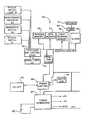
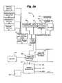
- FIG. 3is a block diagram of an electrical system of the AED
- FIG. 4is a perspective view of the force sensor used in conjunction with a pair of electrodes
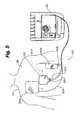
- FIG. 5is a perspective view of the force sensor of the present invention applied to a patent
- FIG. 6is a perspective view of an electrode with the force sensor of the present invention disposed therein,
- FIG. 7is a perspective view of the force sensor of FIG. 6 applied to the chest of a victim;
- FIG. 8is a cross sectional side view of the electrode of the present invention.
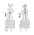
- FIG. 9is a top plan view of a further embodiment of the force sensor of the present invention.
- FIG. 10is a bottom plan view of the force sensor depicted in FIG. 9 ;
- FIG. 11is a cross sectional side view of the electrode of the present invention.
- FIG. 12is a cross sectional side view of the electrode of the present invention.
- FIG. 13is a top plan view of a further embodiment of the force sensor of the present invention.
- FIG. 14is a bottom plan view of the force sensor depicted in FIG. 13 ;
- FIG. 15is a cross sectional side view of the electrode of the present invention.
- FIG. 16is a cross sectional side view of the electrode of the present invention.
- FIG. 17is a top plan view of a further embodiment of the force sensor of the present invention.
- FIG. 18is a bottom plan view of the force sensor depicted in FIG. 17 ;
- FIG. 19is a cross sectional side view of the electrode of the present invention.
- FIG. 20is a partial cut-away view of an embodiment of a packaged electrode system
- FIG. 21is a cross-sectional view of an embodiment of a packaged electrode system and test apparatus
- FIG. 22is a perspective assembly view an embodiment of a packaged electrode system
- FIG. 23is a cross sectional view of an embodiment of a packaged electrode system
- FIG. 24is an partial cut-away view of an embodiment of a packaged electrode system
- FIG. 25is cross sectional view of an embodiment of a packaged electrode system
- FIG. 26is partial cut-away view of an embodiment of a packaged electrode system
- FIG. 27is a cross-sectional view of an embodiment of a packaged electrode system
- FIG. 28is perspective assembly view an embodiment of a packaged electrode system
- FIG. 29is a cross-sectional view of an embodiment of a packaged electrode system
- FIG. 30is a perspective view of an embodiment of a packaged electrode system
- FIG. 31is a cross-sectional view of an embodiment of a packaged electrode system
- FIG. 32is a partial cut-away view of an embodiment of a packaged electrode systsem
- FIG. 33is a cross-sectional view of an embodiment of a packaged electrode system
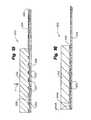
- FIG. 34is a cross-sectional view of a partial embodiment of a packaged electrode system
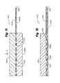
- FIG. 35is a cross-sectional view of a partial embodiment of a packaged electrode system
- FIG. 36is a cross-sectional view of a partial embodiment of a packaged electrode system.
- FIG. 37is a cross-sectional view of a partial embodiment of a packaged electrode system.
- AED 22is shown generally at 22 in FIG. 1 .
- AED 22is used for emergency treatment of victims of cardiac arrest and is typically used by first responders.
- AED 22automatically analyzes a patient's cardiac electrical signal and advises the user to shock a patient upon detection of (1) ventricular fibrillation; (2) ventricular tachycardia; (3) other cardiac rhythms with ventricular rates exceeding 180 beats per minute and having amplitudes of at lease least 0.15 millivolts. When such a condition is detected, AED 22 will build up an electrical charge for delivery to the patient to defibrillate the patient with a defibrillation shock. The operator of AED 22 is guided by voice prompts and an illuminated rescue (shock) button.
- Olson, et al. U.S. Pat. No. 5,645,571, incorporated herein by referencediscloses the general construction and manner of use of an AED.
- AED 22includes case 12 with carrying handle 14 and battery 80 , the battery 80 being removably disposed within a battery compartment (not shown) defined in case 12 .
- Battery 80functions as an energy source for AED 22 .
- Visual maintenance indicator 20 and data access door 44are located on the outside of case 12 to facilitate access by the operator.
- a data communication serial port 42is situated behind data access door 44 .
- Case 12also includes panel 24 and electrode compartment 26 defined in a top portion thereof.
- Panel 24includes illuminable rescue switch 18 and diagnostic display panel 36 with “electrodes” indicator light 28 .
- Panel 24 and electrode compartment 26are enclosed by selectively closeable lid 27 .
- Electrode compartment 26contains connector 32 and electrode package 60 . Electrode compartment 26 hermetically encloses a patient interface which includes a pair of electrodes 50 depicted in FIG. 2 , and a force sensor 200 , FIGS. 4-16 . Electrodes 50 and force sensor 200 are removably connected to connector 32 by lead wires 52 and lead wire connector 58 . Electrodes 50 are attachable to a patient prior to a rescue intervention procedure with AED 22 .
- AED 22also includes a digital microprocessor-based electrical control system (see the block diagram of FIG. 3 ) for controlling overall operation of AED 22 and for delivering a defibrillation shock pulse through electrodes 50 via connector 32 and lead wires 52 .
- the electrical control systemfurther includes an impedance measuring circuit for testing the interconnection and operability of electrodes 50 to detect several faults. For example, if the conductive hydrogel adhesive on electrodes 50 is too dry or if electrodes 50 are not properly connected to connector 32 a relatively high impedance (e.g. greater than about 20 ohms) will be present across connector 32 . However, when fresh electrodes 50 are properly connected, the impedance across connector 32 will be between about 2 and 10 ohms.
- an electrode self-testis conducted (e.g., daily or upon opening lid 27 ) in which the interconnection and operability of electrodes 50 are checked with the impedance measuring circuit. If electrodes 50 are missing or unplugged from connector 32 , if electrodes 50 are damaged, or if the conductive hydrogel adhesive on electrodes 50 is too dry, the control system of AED 22 will illuminate “Electrodes” indicator light 28 on diagnostic display panel 36 .
- Defibrillator 22also includes electrocardiogram (EKG) filter and amplifier 104 which is connected between electrode connector 32 and A/D converter 102 .
- EKGelectrocardiogram
- the EKG or cardiac rhythm of the patientis processed by filter and amplifier 104 in a conventional manner, and digitized by A/D converter 102 before being coupled to processor 74 .
- the rescue mode operation of defibrillator 22is initiated when an operator opens lid 27 to access the electrode package 60 .
- the opening of the lid 27is detected by lid switch 90 , which effectively functions as an on/off switch.
- power control circuit 88activates power generation circuit 84 and initiates rescue mode operation of processor 74 .
- Processor 74then begins its rescue mode operation and initiates the generation of an audible voice prompt “To attempt a rescue, disconnect charger.” if a charger is connected when lid 27 is opened.
- processor 74initiates the generation of an audible “Place electrodes.” voice prompt.
- the operatorshould remove electrode package 60 from compartment 26 , open the package, peel electrodes 50 from the release liner and place the electrodes on the patient's chest. While this action is being performed, processor 74 monitors the impedance signals received through A/D converter 102 to determine whether the impedance across the electrodes indicates that they have been properly positioned on the patient. If the correct impedance is not measured, processor 74 initiates the generation of a “Check electrodes.” voice prompt.
- processor 74After detecting an impedance indicating the proper placement of electrodes 50 , and without further action by the operator (i.e., automatically), processor 74 begins a first analyze sequence by initiating the generation of a “Do not touch patient. Analyzing rhythm.” voice prompt, and analyzing the patient's cardiac rhythm. In one embodiment, processor 74 collects and analyzes a nine second segment of the patient's cardiac rhythm.
- the cardiac rhythm analysis program executed by processor 74is stored in program memory 76 . Algorithms of the type implemented by the rhythm analysis program are generally known and disclosed, for example, in the W. A. Tacker Jr. book Defibrillation of the Heart, 1994 .
- processor 74determines that the patient has a nonshockable cardiac rhythm that is not susceptible to treatment by defibrillation pulses (e.g., no pulse rather than a fibrillating rhythm), it initiates the generation of a “Check pulse. If no pulse, give CPR.” voice prompt. One minute after this voice prompt, processor 74 repeats the initiation of the “Do not touch patient. Analyzing rhythm.” voice prompt and the associated cardiac rhythm analysis.
- processor 74When a shockable cardiac rhythm is detected, processor 74 begins a first charge sequence by initiating the generation of a “Charging.” voice prompt, and causes high voltage generation circuit 86 to operate in the charge mode. When the high voltage generation circuit 86 is charged, processor 74 begins a first shock sequence by initiating the generation of a “Stand clear. Push flashing button to rescue.” voice prompt, and the flashing illumination of rescue switch 18 . The operator actuation of rescue switch 18 will then cause processor 74 to operate high voltage generation circuit 86 in the discharge mode, and results in the application of a defibrillation pulse to the patient to complete the first series of analyze/charge/shock sequences. In one embodiment, the first defibrillation pulse delivered by defibrillator 22 has an energy content of about two hundred joules.
- processor 74times out a short pause of about five seconds to allow the heart to reestablish its cardiac rhythm before beginning a second series of analyze/charge/shock sequences.
- the second series of analyze/charge/shock sequencesis identical to the first series described above, except the energy content of the defibrillation pulse can be about two hundred joules or three hundred joules. If the second series of analyze/charge/shock sequences ends with the delivery of a defibrillation pulse, processor 74 again times out a short pause of about five seconds before beginning a third analyze/charge/shock sequence.
- the third seriesis also identical to the first series, but processor 74 controls the high voltage generation circuit 86 in such a manner as to cause the defibrillation pulse delivered upon the actuation of the rescue switch 18 to have an energy content of about three hundred and sixty joules.
- processor 74Following the delivery of a defibrillation pulse at the end of the third series of analyze/charge/shock sequences, or after identifying a nonshockable cardiac rhythm, processor 74 initiates the generation of a “Check Pulse. If no pulse, give CPR.” voice prompt. Processor 74 then times a one minute CPR period to complete a first set of three series of analyze/charge/shock sequences. Rescue mode operation then continues with additional sets of three series of analyze/charge/shock sequences of the type described above (all with three hundred and sixty joule pulses). Processor 74 ends rescue mode operation of defibrillator 22 when a total of nine series of analyze/charge/shock sequences have been performed, or lid 27 is closed.
- processor 74monitors the impedance present across connector 32 to determine whether electrodes 50 remain properly positioned on the patient. If the monitored impedance is out of range (e.g., too high if the electrodes have come off the patient, or too low is shortened), processor 74 initiates the generation of a “Check Electrodes.” voice prompt, and causes high voltage generation circuit 86 to discharge any charge that may be present through internal load 98 . Rescue mode operation will resume when processor 74 determines that the electrodes have been properly repositioned on the patient.
- FIG. 2is an exploded view of a prior art electrode 50 .
- Electrode 50includes flexible, adhesive coated backing layer 53 (preferably a polymeric foam), and patient engaging layer 54 .
- Patient engaging layer 54is preferably a hydrogel material which has adhesive properties and which is electrically conductive. Hydrogel adhesive of this type is commercially available from LccTcc Corporation (Minnetonka, Minn.) and Tyco International Ltd. (Hamilton, Bermuda).
- Current disbursing flexible conductive portion 56is preferably located between backing layer 53 and patient-engaging hydrogel layer 54 .
- Conductive portion 56as shown, need not be the same size as backing layer 53 and is preferably a homogeneous, solid, thinly deposited metallic substance, or a conductive ink.
- Insulated lead wire 52is terminated with a wire terminal 1 70 .
- Wire terminal 1 70is electrically connected to conductive portion 56 via conductive rivet 1 74 and washer 1 72 .
- Conductive rivet 1 74is covered on a first side with insulating disk 1 76 .
- Conductive rivet 1 74 , washer 1 72 , and wire terminal 1 70are all covered on a second side with insulating pad 1 78 .
- Further examples of electrode pad construction for use with AED 22are described and shown in U.S. Pat. Nos. 5,697,955, 5,579,919, and 5,402,884, all hereby incorporated by reference.
- a packaged electrode system 310is shown to comprise an electrode 311 and a package or enclosure 312 . Also shown in FIG. 21 is a test apparatus 313 .
- the electrode 311is shown to comprise a non-conductive base or backing layer 314 , a conductor or conductive layer 315 , a lead 316 , and a conductive contact layer 317 .
- the base layer 314is preferably constructed of a thin, flexible polymeric substance such as a urethane foam, or a polyester or polyolefin laminate which provides structural base and insulative properties.
- the base layer 314is shown to have a surface area which is substantially coextensive with the surface of the contact layer 317 , it alternatively may be slightly larger. In such larger configurations, the base layer 314 may have a pressure sensitive adhesive disposed on its patient contact side for increased adhesion to the patient body.
- the conductive layer 315is shown to be disposed on the first or patient side of base layer 314 . It functions to transfer (disperse) current or voltage from the lead 316 (or to the lead in a sensing application) to the patient contact layer 317 .
- the conductive layer 315is shown to have a surface area which is smaller than that of the base layer 314 or contact layer 317 , it may alternatively have a dimension which is larger than that shown, or even on which is coextensive with the base and contact layers 314 and 317 .
- the conductive layer 315is preferably a homogeneous, solid, thinly deposited metallic substance, or a conductive ink material.
- the conductive layer 315may be formed of a flexible mesh material, a conductive adhesive or a deposited ink pattern. Flexible conductive ink compounds known in the art have a conductive filler of Gold, Silver, Aluminum or other conductive materials.
- the lead 316is preferably an insulated wire conductor which extends from a mating point with the conductive layer 315 , through the base layer 314 , and then has a freely movable end.
- Various alternatives of this lead 316 designexist and are useable consistent with the general teachings of the invention, including but not limited to uninsulated wire conductors and conductive strips or traces deposited between the contact layer 317 and the base 314 or conductive layers 315 .
- Such a trace or stripmay also extend just beyond the base layer 314 for connection with an ancillary connection means such as a wiring harness including conductive clip means.
- the conductive contact layer 317is preferably a thin layer of semi-liquid gel material.
- the gelmaintains direct electrical contact with the skin, to reduce variations in conductance, and it permits such contact for long periods of time.
- the gelis a conductive, gelatinous compound which is also flexible for contoured adhesion to the body of a patient.
- the gelalso preferably has a pressure sensitive, moisture resistant adhesive property. Compounds having these characteristics have been developed by Minnesota Mining and Manufacturing, Medtronic, and Lec Tec (Synkara TM), Corporations, all of Minnesota, U.S.A. Generally, these compounds have low resistivities.
- the contact layer 317is for direct contact with the patient's body to transfer current or voltage thereto or therefrom. Overall, although the electrode 311 and its constituent elements are shown to have circular configurations, they may alternatively be formed in various other shapes such as rectangular or square patches.
- the package structure 312is shown to have an envelope-like structure formed of a substantially continuous thin, homogeneous layer 318 of a polymeric, preferably non-gas permeable, material.
- the package 387 embodimentmay have a pouch-like structure formed of a pair of thin, flat homogeneous layers 388 and 389 which are sealed or otherwise merged together at their peripheries or outer edges 390 .
- the package 312is shown to have a rectangular configuration various other configurations and shapes are also useable.
- the packagefurther comprises a pair of conductive connectors 319 and 320 which are separated a predetermined distance from one another for contact with separate areas of the contact layer 317 of the enclosed electrode 311 .
- the connectors 319 and 320are conductive areas which are shown to have a unitary construction with the package layer 318 .
- the contacts 319 and 320may alternatively be formed of thin layer strips of conductive material, or a printed conductive ink, disposed on the interior side of the package layer 318 , extending from contact nodes to peripheral contact areas on the exterior of the package 318 .
- Yet another snap-type embodiment 379is shown in FIGS.
- 35 and 36including a connective member 380 disposed on one side of the base layer 318 , and a current dispersion member 381 disposed on the opposite side and being connected to the upper member 380 via an aperture in the base 318 .
- the upper member 380is shown 360 have a base 382 and a mating notch 383 for coupling the lower member 381 .
- the system 310may also include a test apparatus 313 .
- the test apparatus 313includes a current source 323 , preferably a battery, test circuitry 324 , preferably including measurement components and status indication components such as an analog meter, LCD digital display or light emitting diodes, and connectors 321 and 322 for coupling with the package 312 connectors 319 and 320 .
- the test apparatus 313is connected to the package connectors 319 and 320 .
- the test circuitry 324is then activated to form a closed current loop to determine whether continuity exists with respect to the enclosed electrode 311 , thereby indicating whether the electrode 311 is still functional.
- a load 386 formed of for example a conductive and semi-conductive material layers 385 and 386may be added to the current loop as for example is shown in FIG. 37 , for purposes of measuring the magnitude of current flow for more precise measurement of electrode 311 condition.
- a current loopis formed including the connector 319 , the gel of the contact layer 317 (along a substantially horizontal plane), and the connector 320 which is located at a remote location on the contact layer 314 with respect to the connector 319 .
- Currentconducts easily in fresh, semi-liquid gel of the contact layer 317 .
- no current conducts, or current conductionis attenuated, in stale, dried gel. This is indicative of the need to dispose of the stored electrode without using it. And, this condition is determinable without the need to open the package 312 and thereby risk compromising the freshness or sterility of a viable electrode 311 .
- another packaged electrode system 330is shown to comprise an electrode 331 and a package or enclosure 332 .
- the electrode 331is shown to comprise a non-conductive base layer 333 , and a conductive gel layer 336 .
- a conductive snap-type connectorhaving a connection member 335 disposed on one side and a current dispersion member 334 disposed on the second side is also shown.
- the package 332is shown to have at least one body layer 337 with a pair of contacts 338 and 339 disposed at predetermined locations to electrically connect with the gel layer 336 and contact 335 . In a test mode, a current loop is formed between the connector 339 , gel layer 336 , connector portions 334 and 335 and connector 338 .
- another packaged electrode system 345is shown to comprise an electrode 346 and an enclosure 347 .
- the electrode 346is shown to comprise a non-conductive base layer 348 , a conductive gel layer 355 , and a pair of separate conductive layers 349 and 350 , each of which are shown to have a lead 351 and 352 extending therefrom and terminating in a connective node 353 and 354 .
- the lead pair 351 and 352 (and layer pair 349 and 350 )provide a redundant circuit path for increased reliability of use in emergency settings.
- the package 347is shown to have at least one body layer 356 with a pair of contacts 357 and 358 disposed at predetermined locations to electrically couple with connective nodes 353 and 354 .
- a current loopis formed between a connector 357 or 358 , it's respective connective node 353 or 354 and lead 351 or 352 , and its respective conductive layer 349 or 350 .
- a properly functioning electrode 346current conducts through the gel 355 from one conductive layer 349 to the other 350 , and then back to the test apparatus through the above-mentioned path.
- another packaged electrode system 364is shown to comprise an electrode 365 and a unitary package 366 .
- the electrode 365is shown to compromise a non-conductive base layer 367 , and a conductive gel layer 370 .
- a snap-type connector with members 368 and 369electrically couples the gel layer 370 .
- the package 366is shown to have at least one body layer 371 which is coupled to the electrode 365 base layer 367 at tear-away perforated lines 373 .
- a connector 372is shown disposed for contact with the electrode 365 gel layer 370 . In a test mode, a current loop is formed between the connector 372 , the gel layer 370 , and the connector members 368 and 369 .
- another packaged electrode system 397is shown to comprise an electrode 398 and a package.
- the electrode 398is shown to comprise a non-conductive base layer 401 , a conductive gel layer 402 , and a lead 404 having a conductor 405 and an insulator 406 , which is shown to be embedded directly in the gel layer 402 .
- the leadmay be connected to a conductive current dispersion layer (not shown).
- a conductive test strip 403is also shown to be adhered to the surface of the gel 402 at a location remote from the lead 404 for test purposes, and which is designed to release from the gel 402 upon removal of the package layer 399 .
- the packageis shown to have a pair of layers 399 and 400 which overlap to form an interior cavity 407 and area sealingly connected at their peripheries 408 .
- a current loopis formed between the lead 404 , the gel layer 402 and the test strip 403 , which like the lead 404 is shown extended through the package periphery 408 for contact with an external test apparatus.
- another packaged electrode system 414is shown to comprise an electrode 415 and an enclosure.
- the electrode 415is shown to comprise a non-conductive base layer 417 , and a conductive adhesive gel layer 418 which is connected to a snap-type connection node 421 or the like, and an associated lead 420 .
- the packageis shown to comprise a single top layer of non-conductive material 416 which is laminated or adhesively mated to the electrode base layer 417 .
- the gel layer 418is removable from the package layer 416 .
- a test strip 419is disposed on the interior of the package, adhesively connected to the gel layer 418 , and extending to the package exterior. In a test mode, a current loop is formed between the lead 420 , node 421 , gel layer 418 and the test strip 419 .
- another packaged electrode system 427is shown to comprise a pair of electrodes 428 and 429 and a package.
- the electrodes 428 and 429are shown to comprise non-conductive base layers 430 and 433 , and conductive gel layers 431 and 434 .
- Leads 432 and 435extend from the respective gel layers 431 and 434 .
- the packageis shown to have a pair of overlapping layers 442 and 443 which are sealed at their peripheries 441 to form an enclosure 440 housing the electrodes 428 and 429 .
- the electrodes 428 and 429are oriented with their respective gel layers 431 and 434 mating with a resistive layer 437 (and an optional separator layer 436 ) formed of a conductive/resistive material as known in the art.
- a conductive lead 439 or stripextends from the resistive layer through the package periphery 441 , as do the electrode leads 432 and 435 .
- a current loopis formed between, for example, a lead 432 , a gel layer 431 , the resistive layer 437 , and the remaining gel layer 434 and lead 435 .
- the circuitcan be altered to include the lead 439 .
- FIG. 3is a block diagram of electrical system 70 of AED 22 .
- the overall operation of AED 22is controlled by a digital microprocessor-based control system 72 which includes a processor 74 interfaced to program memory 76 , data memory 77 , event memory 78 and real time clock 79 .
- the operating program executed by processor 74is stored in program memory 76 .
- Electrical poweris provided by the battery 80 which is removably positioned within the battery compartment of AED 22 and is connected to power generation circuit 84 .
- Power generation circuit 84is also connected to lid switch 90 , watch dog timer 92 , real time clock 79 and processor 74 .
- Lid switch 90is a magnetic read relay switch in one embodiment, and provides signals to processor 74 indicating whether lid 27 is open or closed.
- Data communication port 42is coupled to processor 74 for two-way serial data transfer using an RS-232 protocol.
- Rescue switch 18 , maintenance indicator 20 , the indicator lights of diagnostic display panel 36 , the voice circuit 94 and piezoelectric audible alarm 96are also connected to processor 74 .
- Voice circuit 94is connected to speaker 34 . In response to voice prompt control signals from processor 74 , circuit 94 and speaker 34 generate audible voice prompts for consideration by a rescuer.
- High voltage generation circuit 86is also connected to and controlled by processor 74 . Circuits such as high voltage generation circuit 86 are generally known, and disclosed, for example, in the commonly assigned Persson et al. U.S. Pat. No. 5,405,361, which is hereby incorporated by reference. In response to charge control signals provided by processor 74 , high voltage generation circuit 86 is operated in a charge mode during which one set of semiconductor switches (not separately shown) cause a plurality of capacitors (also not shown), to be charged in parallel to the 12V potential supplied by power generation circuit 84 .
- high voltage generation circuit 86is operated in a discharge mode during which the capacitors are discharged in series by another set of semiconductor switches (not separately shown) to produce the high voltage defibrillation pulses.
- the defibrillation pulsesare applied to the patient by electrodes 50 through connector 32 connected to the high voltage generation circuit 86 .
- Impedance measuring circuit 100is connected to both connector 32 and real time clock 79 . Impedance measuring circuit 100 is interfaced to processor 74 through analog-to-digital (A/D) converter 102 . Impedance measuring circuit 100 receives a clock signal having a predetermined magnitude from clock 79 , and applies the signal to electrodes 50 through connector 32 . The magnitude of the clock signal received back from electrodes 50 through connector 32 is monitored by impedance measuring circuit 100 . An impedance signal representative of the impedance present across electrodes 50 is then generated by circuit 100 as a function of the ratio of the magnitudes of the applied and received clock signals (i.e., the attenuation of the applied signal).
- a relatively low resistancee.g., less than about 10 ohms
- a relatively high resistancee.g., greater than about two hundred fifty ohms
- the resistance across electrodes 50will then be between about twenty-five and two hundred fifty ohms when fresh electrodes 50 are properly positioned on the patient with good electrical contacts. It should be noted that these resistance values are given as exemplary ranges and are not meant to be absolute ranges.
- the impedance signal representative of the impedance measured by circuit 100is digitized by A/D converter 102 and provided to processor 74 .
- Impedance measuring circuit 110is connected to connector 32 and real time clock 79 , and is interfaced to processor 74 through analog-to-digital (A/D) converter 102 .
- Impedance measuring circuit 110receives a clock signal having a predetermined magnitude from clock 79 , and applies the signal to force sensor 200 through connector 32 .
- the magnitude of the clock signal received back from force sensor 200 through connector 32is monitored by impedance measuring circuit 110 .
- An impedance signal representative of the impedance present across force sensor 200is then generated by circuit 110 as a function of the ratio of the magnitudes of the applied and received clock signals (i.e., the attenuation of the applied signal).
- the impedance signal representative of the impedance measured by circuit 110is digitized by A/D converter 102 and provided to processor 74 .
- FIG. 4is a plan view of a patient interface 120 for use with AED 22 .
- Patient interface 120includes connector 58 which is adapted to releasably mate with connector 32 of AED 22 .
- Four lead wires 52 A, 52 B, 52 C, and 52 Dare all terminated with connector 58 .
- Patient interface 120also includes a force sensing pad 102 which includes a force sensor 200 .
- Lead wires 52 C and 52 Dare electrically connected to force sensor 200 .
- Electrodes 50 A and 50 Beach include backing layer 53 , patient engaging hydrogel layer 54 , conductive portion 56 , and insulating pad 78 .
- FIG. 5is a plan view illustrating patient interface 120 applied to human torso 98 of the victim 112 .
- Force sensing pad 102is applied over the sternum of torso 98 .
- Force sensing pad 102may be adhered with pressure sensitive adhesive.
- Force sensing pad 102includes force sensor 200 which is electrically connected to lead wires 52 C and 52 D.
- Electrode 50 Ais shown applied to the upper right chest of torso 98 . Electrode 50 A is electrically connected to lead wire 52 A. Electrode 50 B is applied to the lower left side of torso 98 and is electrically connected to lead wire 52 B. Lead wires 52 A, 52 B, 52 C, and 52 D are terminated with connector 58 . Connector 58 is adapted to make releasable, electrical contact with connector 32 of AED 22 .
- electrodes 50 A, 50 B and force sensing pad 102may be placed in locations on torso 98 other than those shown in FIG. 5 without deviating from the spirit or scope of this invention.
- FIG. 6is a plan view of a patient interface 130 for use with AED 22 .
- Interface 130includes a second preferred embodiment of force sensor 200 .
- Patient interface 130includes connector 58 which is adapted to releasably mate with connector 32 of AED 22 .
- Four lead wires 52 A, 52 B, 52 C, and 52 Dare all terminated with connector 58 .
- Patient interface 130also includes force sensor 200 which is positioned between backing layer 153 and insulating pad 178 of electrode 150 A. Lead wires 52 C and 52 D are electrically connected to force sensor 200 .
- Electrodes 150 A and 150 Beach include patient engaging hydrogel layer 54 , and conductive portion 56 .
- FIG. 7is a plan view illustrating patient interface 130 applied to torso 98 .
- Force sensor 200is positioned over the sternum of torso 98 .
- Force sensor 200is electrically connected to lead wires 52 C and 52 D.
- Electrode 150 Ais shown applied to torso 98 .
- Electrode 150 Ais electrically connected to lead wire 52 A.
- Electrode 150 Bis applied to the lower left side of torso 98 and is electrically connected to lead wire 52 B.
- Lead wires 52 A, 52 B, 52 C, and 52 Dare terminated with connector 58 (not shown).
- Connector 58is adapted to make releasable, electrical contact with connector 32 (not shown) of AED 22 .
- FIG. 8is a cross section illustrating an embodiment of a force sensor 200 .
- Force sensor 200has a first side 210 and a second side 220 .
- Force sensor 200includes a substrate 202 .
- a conductive pattern 204 A, 204 Bis situated on each side of the substrate layer.
- Substrate 202may be any thin (e.g. about 0.002′′ to 0.020′′) nonconductive sheet of material. Plastic film materials such as polyester, polycarbonate, PVC, etc. have been found to work well as substrate 202 .
- Conductive patterns 204 A, 204 Bmay be any conductive material such as copper foil, nickel foil, or conductive ink.
- substrate 202is 5 mil polyester and conductive patterns 204 A, 204 B are silver conductive ink.
- Substrate 202includes apertures 208 .
- Conductive pads 206 A and 206 Bare situated on each side of substrate 202 as shown in FIG. 8 .
- Conductive pads 206 A, 206 Bare preferably made of a deformable, conductive material. Materials which have been found suitable include conductive silicone rubber, conductive foam rubber, and conductive urethane rubber.
- FIG. 9is a plan view illustrating first side 210 of force sensor 200 with conductive pads 206 A, 206 B removed. Conductive pattern 204 A is seen situated on substrate 202 . Apertures 208 are cut through conductive pattern 204 A, substrate 202 , and conductive pattern 204 B, underlying substrate 202 .
- FIG. 10is a plan view illustrating second side 220 of force sensor 200 with conductive pads 206 A, 206 B removed. Conductive pattern 204 B is seen situated on substrate 202 . As also shown in FIG. 9 , apertures 208 are cut through conductive pattern 204 B, substrate 202 , and conductive pattern 204 A, underlying substrate 202 .
- conductive patterns 204 A, 204 Beach include conductive traces 212 A, 212 B.
- Wire terminals 214 A, 214 Bare arranged make electrical contact with conductive traces 212 A, 212 B respectively.
- Wire terminals 214 A, 214 Bare attached to substrate 202 with rivets 216 A, 216 B and washers 218 A, 218 B.
- Lead wires 222 A, 222 Bare terminated with wire terminals 214 A, 214 B.
- lead wires 222 A, 222 Bmay be used to attach lead wires 222 A, 222 B to conductive traces 212 A, 212 B. Possible methods include soldering, the use of a connector designed to mate with flexible circuits, and the use of conductive adhesive.
- FIG. 11is a section view of force sensor 200 with a compressive force F applied.
- force sensor 200When force sensor 200 is used, it is placed between two objects, such as the sternum of a cardiac arrest victim and the heel of a rescuer's hand. When the rescuer presses down with the heel of his or her hand, the force results in pressure distributed across the area of the heel of his or her hand.
- conductive pads 206 A, 206 BWhen pressure is applied to force sensor 200 , conductive pads 206 A, 206 B extrude through apertures 208 . When pads 206 A, 206 B contact each other, they complete an electrical circuit between conductive layer 204 A and conductive layer 204 B. Increasing the force F applied to force sensor 200 increases the surface area of the electrical connection between conductive pads 206 A, 206 B, thereby decreasing the electrical resistance between pads 206 A, 206 B. The electrical resistance of the circuit between conductive layer 204 A and conductive layer 204 B is therefore indicative of the magnitude of the force F applied to force sensor 200 .
- FIGS. 12-14illustrate a further preferred embodiment of force sensor 200 .
- Force sensor 200includes a first substrate 222 .
- a conductive pattern 224is situated on first substrate 222 .
- substrate 222may be any thin (e.g. about 0.002′′ to 0.010′′) nonconductive sheet of material.
- Plastic film materialssuch as polyester, polycarbonate, PVC, etc. have been found to work well as substrate 222 .
- Conductive pattern 224may be any conductive material such as copper foil, nickel foil, or conductive ink.
- substrate layer 222is 5 mil polyester and conductive pattern 224 is silver conductive ink.
- Force sensor 200includes second substrate 226 .
- a conductive pattern 228is situated on second substrate 226 .
- Second substrate 226is situated on first substrate 222 .
- First substrate 222 and second substrate 226may be held together with a layer of pressure sensitive adhesive (not shown).
- Substrate 222includes apertures 230 .
- a conductive pad 232is situated on, and makes electrical contact with conductive pattern 224 as shown in FIG. 14 .
- Conductive pad 232is preferably made of a deformable, conductive material. Materials which have been found suitable include conductive silicone rubber, conductive foam rubber, and conductive urethane rubber.
- FIG. 13is a plan view illustrating second substrate 226 and conductive pattern 228 .
- FIG. 14is a plan view illustrating first substrate 222 and conductive pattern 224 .
- FIG. 15is a section view of the force sensor 200 of FIG. 12 with a force F applied.
- force sensor 200When force sensor 200 is used, it is placed between two objects, such as the sternum of a cardiac arrest victim and the heel of a rescuers hand. When the rescuer presses down with the heel of his or her hand, the force results in pressure distributed across the area of the heel of his or her hand.
- conductive pad 232When a force F is applied to force sensor 200 , conductive pad 232 extrudes through apertures 230 . When conductive pad 232 contacts conductive pattern 228 it completes an electrical circuit between conductive pattern 224 and conductive pattern 228 . Increasing the force F applied to force sensor 200 increases the surface area of the electrical connection between conductive pads 232 and conductive pattern 228 , thereby reducing the electrical resistance between pad 232 and pattern 228 . Accordingly, change in contact area creates a change in electrical resistance which is indicative of the force applied to force sensor 200 .
- FIGS. 16-18illustrate another third embodiment of force sensor 200 .
- force sensor 200includes a first substrate 242 .
- Two conductive patterns 244 A, 244 Bare situated on first substrate 242 .
- Force sensor 200includes second substrate 246 which includes apertures 250 .
- Second substrate 246is comprised of a non-conductive material. Polyester, polyethylene, and polypropylene have been found to be suitable materials for second substrate 246 .
- a conductive pad 252is situated on second substrate 246 .
- conductive pad 232is preferably made of a deformable, conductive material.
- FIG. 17is a plan view illustrating first substrate 242 and conductive patterns 244 A, 244 B.
- the conductive patterns 244 A, 244 Bare arranged so that they are in close proximity to each other. Small gaps 256 are left between conductive paths 244 A, 244 B so that there is no direct electrical contact between conductive paths 244 A, 244 B.
- FIG 18is a plan view illustrating second substrate 246 and apertures 250 .
- FIG. 19is a section view of the force sensor 200 of FIGS. 16-18 with a force F applied.
- force sensor 200When force sensor 200 is used, it is placed between two objects, such as the sternum of a cardiac arrest victim and the heel of a rescuers hand. When the rescuer presses down with the heel of his or her hand, the force F results in pressure distributed across the area of the heel of his or her hand.
- conductive pad 252When pressure is applied to force sensor 200 , conductive pad 252 extrudes through apparatus 250 . When conductive pad 252 contacts conductive patterns 244 A, 244 B it completes an electrical circuit between conductive pattern 244 A and conductive pattern 244 B. Increasing the force applied to force sensor 200 increases the surface area of the electrical connection between conductive pad 252 and conductive patterns 244 A, 244 B. This change in contact area creates a change in electrical resistance which is indicative of the force applied to force sensor 200 .
- force sensor 200is positioned on the sternum of a victim 112 .
- the rescuerplaces the heel of his or her hand onto force sensor 200 and delivers chest compressions to the chest of the victim 112 .
- Force sensor 200 and impedance measuring circuit 110produce an electrical signal proportional to the force applied to the victim's chest. This signal indicates to processor 74 the rate and magnitude of the chest compressions which the victim 112 is receiving. This signal also allows processor 74 to determine the precise time that a rescuer has begun (or stopped) CPR.
- Processor 74compares the measured rate of chest compressions to a range of desired values.
- processor 74will produce a control signal which causes voice circuit 94 and speaker 34 to generate an appropriate voice prompt such as “faster”. If the current chest compression rate value is greater than the desired range, processor 74 will produce a control signal which causes voice circuit 94 and speaker 34 to generate an appropriate voice prompt such as “slower”.
- Processor 74also compares the measured chest compression force to a range of desired values. If the chest compression force delivered by the rescuer is less than the desired range, processor 74 will produce a control signal which causes voice circuit 94 and speaker 34 to generate an appropriate voice prompt such as “harder”. If the chest compression force is greater than the desired range, processor will produce a control signal which causes voice circuit 94 and speaker 34 to generate an appropriate voice prompt such as “softer”.
- AED 22may also provide other types of audible feedback to the rescuer.
- AED 22may give an audible signal each time the force measured using force sensor 200 reaches a desired value.
Landscapes
- Health & Medical Sciences (AREA)
- Cardiology (AREA)
- Heart & Thoracic Surgery (AREA)
- Animal Behavior & Ethology (AREA)
- Veterinary Medicine (AREA)
- Public Health (AREA)
- General Health & Medical Sciences (AREA)
- Life Sciences & Earth Sciences (AREA)
- Biomedical Technology (AREA)
- Radiology & Medical Imaging (AREA)
- Nuclear Medicine, Radiotherapy & Molecular Imaging (AREA)
- Engineering & Computer Science (AREA)
- Emergency Medicine (AREA)
- Pulmonology (AREA)
- Epidemiology (AREA)
- Pain & Pain Management (AREA)
- Physical Education & Sports Medicine (AREA)
- Rehabilitation Therapy (AREA)
- Electrotherapy Devices (AREA)
Abstract
Description
- sensing a force applied by the rescuer to the victim's sternum;
- sensing an interval between successive applications of force to the victim's sternum;
- comparing the force applied by the rescuer to the victim's sternum in a standard of force known to effect resuscitation;
- providing a prompt to the rescuer that prompts the rescuer to vary the force delivered to approximate the force that is known to effect resuscitation;
- comparing the interval between successive applications of force to the victim's sternum to a standard interval known to effect resuscitation; and
- providing a prompt to the rescuer that prompts the rescuer to vary the interval of force application to approximate the interval that is known to effect resuscitation.
Claims (46)
Priority Applications (1)
| Application Number | Priority Date | Filing Date | Title |
|---|---|---|---|
| US10/255,988USRE40471E1 (en) | 1998-10-29 | 2002-09-25 | AED with force sensor |
Applications Claiming Priority (2)
| Application Number | Priority Date | Filing Date | Title |
|---|---|---|---|
| US09/182,831US6125299A (en) | 1998-10-29 | 1998-10-29 | AED with force sensor |
| US10/255,988USRE40471E1 (en) | 1998-10-29 | 2002-09-25 | AED with force sensor |
Related Parent Applications (1)
| Application Number | Title | Priority Date | Filing Date |
|---|---|---|---|
| US09/182,831ReissueUS6125299A (en) | 1998-10-29 | 1998-10-29 | AED with force sensor |
Publications (1)
| Publication Number | Publication Date |
|---|---|
| USRE40471E1true USRE40471E1 (en) | 2008-08-26 |
Family
ID=22670234
Family Applications (2)
| Application Number | Title | Priority Date | Filing Date |
|---|---|---|---|
| US09/182,831CeasedUS6125299A (en) | 1998-10-29 | 1998-10-29 | AED with force sensor |
| US10/255,988Expired - LifetimeUSRE40471E1 (en) | 1998-10-29 | 2002-09-25 | AED with force sensor |
Family Applications Before (1)
| Application Number | Title | Priority Date | Filing Date |
|---|---|---|---|
| US09/182,831CeasedUS6125299A (en) | 1998-10-29 | 1998-10-29 | AED with force sensor |
Country Status (1)
| Country | Link |
|---|---|
| US (2) | US6125299A (en) |
Cited By (22)
| Publication number | Priority date | Publication date | Assignee | Title |
|---|---|---|---|---|
| US20060167505A1 (en)* | 2005-01-26 | 2006-07-27 | Medtronic Emergency Response Systems, Inc. | Defibrillator with overridable CPR-first protocol |
| US20080300518A1 (en)* | 2007-06-01 | 2008-12-04 | Bowes C J | System, method, and apparatus for assisting a rescuer in resuscitation |
| US20100168809A1 (en)* | 2004-05-07 | 2010-07-01 | Zoll Medical Corporation | Automated caregiving device with prompting based on caregiver process |
| US20100221691A1 (en)* | 2005-09-14 | 2010-09-02 | Freeman Gary A | Synchronization of Repetitive Therapeutic Interventions |
| US20120183942A1 (en)* | 2011-01-17 | 2012-07-19 | Pastrick John J | Manikin Sensing Pads and Liners in an AED Training System |
| USD671649S1 (en) | 2011-12-07 | 2012-11-27 | Cardiac Sciences Corporation | Cardiopulmonary resuscitation assist device |
| USD675739S1 (en) | 2011-12-07 | 2013-02-05 | Cardiac Science Corporation | Automated external defibrillator electrode pad |
| US8600522B2 (en) | 2006-05-26 | 2013-12-03 | Cardiac Science Corporation | CPR feedback method and apparatus |
| US20140099618A1 (en)* | 2012-10-10 | 2014-04-10 | Bt Inc. | Cardiopulmonary resuscitation (cpr) simulator enabling repeated defibrillation training |
| US20140148869A1 (en)* | 2012-05-03 | 2014-05-29 | Physio-Control, Inc. | External Defibrillator Electrode, Method and System for Reducing ECG Artifact |
| US9126055B2 (en) | 2012-04-20 | 2015-09-08 | Cardiac Science Corporation | AED faster time to shock method and device |
| US9370462B2 (en) | 2010-06-30 | 2016-06-21 | Koninklijke Philips N.V. | Pediatric patient-safe CPR device |
| US9782123B2 (en) | 2004-09-30 | 2017-10-10 | Zoll Medical Corporation | Integrated resuscitation |
| US10617599B2 (en) | 2002-10-25 | 2020-04-14 | Zoll Medical Corporation | System for determining depth of chest compressions during CPR |
| USD926323S1 (en) | 2020-03-30 | 2021-07-27 | Zoll Medical Corporation | Automated external defibrillator electrode pad |
| WO2021188383A1 (en)* | 2020-03-16 | 2021-09-23 | New York University | Apparatus for determining shear forces in regard to a pressure imaging array, single point sensor for shear forces, and method |
| US11179286B2 (en) | 2016-10-21 | 2021-11-23 | Zoll Medical Corporation | Adaptive body positioning |
| US11944582B2 (en) | 2013-04-30 | 2024-04-02 | Zoll Medical Corporation | Compression depth monitor with variable release velocity feedback |
| US12042653B2 (en) | 2021-12-30 | 2024-07-23 | Pulse Biosciences, Inc. | Electrical applicators with non-penetrating electrodes for applying energy to tissue surfaces |
| US12233020B2 (en) | 2016-10-21 | 2025-02-25 | Zoll Medical Corporation | System and methods for adaptive body positioning during chest compressions |
| USD1084345S1 (en) | 2022-07-28 | 2025-07-15 | Zoll Medical Corporation | Chest compression sensor |
| USD1084346S1 (en) | 2022-07-28 | 2025-07-15 | Zoll Medical Corporation | Chest compression sensor |
Families Citing this family (82)
| Publication number | Priority date | Publication date | Assignee | Title |
|---|---|---|---|---|
| US6174295B1 (en) | 1998-10-16 | 2001-01-16 | Elroy T. Cantrell | Chest mounted cardio pulmonary resuscitation device and system |
| DE19848146C2 (en)* | 1998-10-20 | 2002-10-02 | Henkel Kgaa | Use of a hot melt adhesive for bonding DVDs and process for their production |
| US6390996B1 (en)* | 1998-11-09 | 2002-05-21 | The Johns Hopkins University | CPR chest compression monitor |
| NO310137B1 (en)* | 1998-12-11 | 2001-05-28 | Laerdal Medical As | System for measuring and analyzing CPR parameters for use with and by an external defibrillator |
| NO310135B1 (en)* | 1999-05-31 | 2001-05-28 | Laerdal Medical As | System for measuring and applying parameters when performing chest compression in the course of a life-saving situation or training situation as well as applications |
| US6440082B1 (en)* | 1999-09-30 | 2002-08-27 | Medtronic Physio-Control Manufacturing Corp. | Method and apparatus for using heart sounds to determine the presence of a pulse |
| US9248306B2 (en) | 1999-09-30 | 2016-02-02 | Physio-Control, Inc. | Pulse detection apparatus, software, and methods using patient physiological signals |
| US20030109790A1 (en) | 2001-12-06 | 2003-06-12 | Medtronic Physio-Control Manufacturing Corp. | Pulse detection method and apparatus using patient impedance |
| US20040039419A1 (en)* | 1999-09-30 | 2004-02-26 | Stickney Ronald E. | Apparatus, software, and methods for cardiac pulse detection using a piezoelectric sensor |
| US20060064131A1 (en)* | 2000-02-04 | 2006-03-23 | Freeman Gary A | User interface for defibrillator for use by persons with limited training and experience |
| JP2003521355A (en) | 2000-02-04 | 2003-07-15 | ゼットエムデー コーポレイション | Integrated resuscitation |
| DE10128979B4 (en)* | 2001-06-08 | 2011-12-08 | Corscience Gmbh & Co.Kg | Therapy device and associated control unit |
| US7569021B2 (en) | 2002-03-21 | 2009-08-04 | Jolife Ab | Rigid support structure on two legs for CPR |
| US8527044B2 (en)* | 2002-05-15 | 2013-09-03 | Physio-Control, Inc. | User interface method and apparatus for a medical device |
| US20040039420A1 (en)* | 2002-08-26 | 2004-02-26 | Medtronic Physio-Control Manufacturing Corp. | Apparatus, software, and methods for cardiac pulse detection using accelerometer data |
| US20040116969A1 (en) | 2002-08-26 | 2004-06-17 | Owen James M. | Pulse detection using patient physiological signals |
| US20040162510A1 (en)* | 2003-02-14 | 2004-08-19 | Medtronic Physio-Control Corp | Integrated external chest compression and defibrillation devices and methods of operation |
| US7308304B2 (en)* | 2003-02-14 | 2007-12-11 | Medtronic Physio-Control Corp. | Cooperating defibrillators and external chest compression devices |
| US20050038475A1 (en)* | 2003-02-18 | 2005-02-17 | Medtronic Physio-Control Corp. | Defibrillators learning of other concurrent therapy |
| US7569018B1 (en) | 2003-02-18 | 2009-08-04 | Purdue Research Foundation | Apparatus and method for noninvasively detecting the quality of cardiac pumping |
| US6961612B2 (en) | 2003-02-19 | 2005-11-01 | Zoll Medical Corporation | CPR sensitive ECG analysis in an automatic external defibrillator |
| CN1756711A (en)* | 2003-06-18 | 2006-04-05 | 东芝电梯株式会社 | Sheaves for elevators |
| US7190999B2 (en)* | 2003-06-27 | 2007-03-13 | Zoll Medical Corporation | Cardio-pulmonary resuscitation device with feedback from measurement of pulse and/or blood oxygenation |
| US7220235B2 (en) | 2003-06-27 | 2007-05-22 | Zoll Medical Corporation | Method and apparatus for enhancement of chest compressions during CPR |
| WO2005000392A2 (en)* | 2003-06-27 | 2005-01-06 | Koninklijke Philips Electronics N.V. | Method of detecting when electrode pads have been handled or removed from their package |
| US20050070963A1 (en)* | 2003-09-30 | 2005-03-31 | Wilson Ellen Bartlett | Hair-removal apparatus for preparing a human torso for the use of an automated external defibrillator |
| JP2012091021A (en) | 2003-11-06 | 2012-05-17 | Zoll Medical Corp | Device for analyzing physiological signal during application of chest compression |
| US20050101889A1 (en)* | 2003-11-06 | 2005-05-12 | Freeman Gary A. | Using chest velocity to process physiological signals to remove chest compression artifacts |
| JP4717877B2 (en)* | 2004-04-12 | 2011-07-06 | ゾール メディカル コーポレイション | Automatic pediatric defibrillator |
| US7565194B2 (en) | 2004-05-12 | 2009-07-21 | Zoll Medical Corporation | ECG rhythm advisory method |
| WO2005112749A1 (en) | 2004-05-12 | 2005-12-01 | Zoll Medical Corporation | Ecg rhythm advisory method |
| GB0414054D0 (en) | 2004-06-23 | 2004-07-28 | Owen Mumford Ltd | Improvements relating to automatic injection devices |
| EP1778083B1 (en)* | 2004-07-15 | 2010-05-26 | Laerdal Medical AS | Method and system for monitoring ventilations |
| WO2006015348A2 (en) | 2004-07-30 | 2006-02-09 | Access Cardiosystems, Inc. | Detectin g artifact signals caused by cpr or patient motion |
| US20060022645A1 (en) | 2004-07-30 | 2006-02-02 | Bowers Kyle R | Method and apparatus for determining battery capacity in a defibrillator |
| US7805191B2 (en)* | 2005-01-31 | 2010-09-28 | Physio-Control, Inc. | CPR time indicator for a defibrillator data management system |
| WO2006104977A2 (en) | 2005-03-25 | 2006-10-05 | Zoll Medical Corporation | Integrated resuscitation |
| EP1951126A2 (en) | 2005-11-17 | 2008-08-06 | Koninklijke Philips Electronics N.V. | Cpr guided by vascular flow measurement |
| WO2007081609A2 (en)* | 2005-11-18 | 2007-07-19 | Scientific Pathways International, Llc | Cpr analysis system and method |
| EP1986740A2 (en)* | 2006-02-15 | 2008-11-05 | Koninklijke Philips Electronics N.V. | Cpr assistance and effectiveness display |
| US7747319B2 (en) | 2006-03-17 | 2010-06-29 | Zoll Medical Corporation | Automated resuscitation device with ventilation sensing and prompting |
| KR101396797B1 (en) | 2006-06-30 | 2014-05-26 | 애브비 바이오테크놀로지 리미티드 | Automatic injection device |
| JP5281011B2 (en) | 2006-11-14 | 2013-09-04 | コーニンクレッカ フィリップス エレクトロニクス エヌ ヴィ | Cardiopulmonary resuscitation guidance device with reduced motion sensitivity |
| JP2012518454A (en) | 2009-02-24 | 2012-08-16 | コーニンクレッカ フィリップス エレクトロニクス エヌ ヴィ | Ultrasonic blood flow sensor with triangular sensor structure |
| EP2228097B1 (en) | 2009-03-11 | 2016-01-27 | Schiller Medical S.A.S. | Defibrillator, rescue kit of parts and process for controlling the quality of chest compressions |
| US8509881B2 (en)* | 2009-11-03 | 2013-08-13 | Cardiac Science Corporation | True ECG measurement during cardio pulmonary resuscitation by adaptive piecewise stitching algorithm |
| US9468581B2 (en) | 2010-11-29 | 2016-10-18 | Hitachi, Ltd. | Compression depth calculation system and compression depth calculation method |
| BR112013018905B1 (en) | 2011-01-24 | 2021-07-13 | Abbvie Biotechnology Ltd | AUTOMATIC INJECTION DEVICES THAT HAVE OVERMOLDED HANDLE SURFACES. |
| US8781577B2 (en) | 2011-04-08 | 2014-07-15 | Zoll Medical Corporation | Coordinated resuscitation perfusion support |
| US10238574B2 (en) | 2011-04-08 | 2019-03-26 | Zoll Medical Corporation | System for assisting rescuers in performing cardio-pulmonary resuscitation (CPR) on a patient |
| WO2013016640A2 (en)* | 2011-07-27 | 2013-01-31 | Zoll Medical Corporation | Method and apparatus for monitoring manual chest compression efficiency during cpr |
| ES2587993T3 (en) | 2012-03-02 | 2016-10-28 | Abbvie Inc. | Automatic injection learning device |
| US8942800B2 (en) | 2012-04-20 | 2015-01-27 | Cardiac Science Corporation | Corrective prompting system for appropriate chest compressions |
| US20140005506A1 (en) | 2012-06-29 | 2014-01-02 | Zoll Medical Corporation | Rescue scene video transmission |
| US10420702B2 (en) | 2013-02-20 | 2019-09-24 | Physio-Control, Inc. | CPR quality assessment accounting for pause aspect |
| US10490308B2 (en) | 2013-02-20 | 2019-11-26 | Physio-Control, Inc. | Context-sensitive chest compression fraction measurement for CPR quality assessment |
| US8798743B1 (en)* | 2013-03-04 | 2014-08-05 | Zoll Medical Corporation | Self-contained cardiac response unit |
| EP2967394A4 (en) | 2013-03-15 | 2016-11-09 | Zoll Medical Corp | Ecg noise reduction system for removal of vehicle motion artifact |
| EP2969034A4 (en) | 2013-03-15 | 2016-11-30 | Zoll Medical Corp | IMPEDANCE SIGNAL PROCESSING FOR BREATHING DETECTION |
| AU2014292850B2 (en) | 2013-07-25 | 2019-04-11 | Physio-Control, Inc. | Electrode assembly having various communicative solutions |
| US20150088016A1 (en) | 2013-09-25 | 2015-03-26 | Zoll Medical Corporation | Mobile Device Control |
| US10596064B2 (en) | 2014-03-18 | 2020-03-24 | Zoll Medical Corporation | CPR chest compression system with tonometric input and feedback |
| US10004662B2 (en) | 2014-06-06 | 2018-06-26 | Physio-Control, Inc. | Adjustable piston |
| US11246796B2 (en) | 2014-06-06 | 2022-02-15 | Physio-Control, Inc. | Adjustable piston |
| US10092464B2 (en) | 2014-10-03 | 2018-10-09 | Physio-Control, Inc. | Medical device stabilization strap |
| US20160184180A1 (en)* | 2014-12-26 | 2016-06-30 | Sumitomo Riko Company Limited | Cardiopulmonary resuscitation support device |
| JP6714330B2 (en)* | 2014-12-26 | 2020-06-24 | 住友理工株式会社 | Cardiopulmonary resuscitation assist device |
| EP3673953B1 (en) | 2015-03-27 | 2022-09-14 | Zoll Medical Corporation | Ecg and defibrillator electrode detection and tracking system |
| CN108136192A (en) | 2015-10-16 | 2018-06-08 | Zoll医疗公司 | For providing the dual sensor electrode of the recovery feedback of enhancing |
| US10639234B2 (en) | 2015-10-16 | 2020-05-05 | Zoll Circulation, Inc. | Automated chest compression device |
| US10682282B2 (en) | 2015-10-16 | 2020-06-16 | Zoll Circulation, Inc. | Automated chest compression device |
| JP6746347B2 (en)* | 2016-03-30 | 2020-08-26 | 住友理工株式会社 | Cardiopulmonary resuscitation assist device |
| US10449380B2 (en) | 2016-12-12 | 2019-10-22 | Revive Solutions, Inc. | Defibrillator |
| JP7257681B2 (en) | 2016-12-12 | 2023-04-14 | アバイブ・ソリューションズ・インコーポレーテッド | defibrillator |
| US10903675B2 (en) | 2016-12-12 | 2021-01-26 | Avive Solutions, Inc. | Medical device draw current regulation |
| US11607555B2 (en) | 2016-12-12 | 2023-03-21 | Avive Solutions, Inc. | Defibrillator discharge control |
| US11246795B2 (en) | 2017-04-20 | 2022-02-15 | Zoll Circulation, Inc. | Compression belt assembly for a chest compression device |
| US10874583B2 (en) | 2017-04-20 | 2020-12-29 | Zoll Circulation, Inc. | Compression belt assembly for a chest compression device |
| CN107812324A (en)* | 2017-11-24 | 2018-03-20 | 合肥大族科瑞达激光设备有限公司 | A kind of semiconductor laser therapeutic instrument |
| US10905629B2 (en) | 2018-03-30 | 2021-02-02 | Zoll Circulation, Inc. | CPR compression device with cooling system and battery removal detection |
| WO2022051672A1 (en) | 2020-09-04 | 2022-03-10 | Zoll Medical Corporation | Medical treatment system with companion device |
| US11794025B1 (en) | 2022-04-04 | 2023-10-24 | Altrix Medical, Inc. | Compact AED with integrated CPR coaching |
Citations (58)
| Publication number | Priority date | Publication date | Assignee | Title |
|---|---|---|---|---|
| US3685645A (en) | 1970-08-17 | 1972-08-22 | Physio Control Corp | Defibrillation electrode pad and package therefor |
| US3857398A (en) | 1971-12-13 | 1974-12-31 | L Rubin | Electrical cardiac defibrillator |
| US3862636A (en) | 1972-01-20 | 1975-01-28 | Health Technology Labs Inc | Computer controlled defibrillator |
| US4034854A (en) | 1976-07-16 | 1977-07-12 | M I Systems, Inc. | Electrode package |
| US4096856A (en) | 1976-09-03 | 1978-06-27 | Physio-Control Corporation | Portable electronic physiological instrument having separable first and second components, and improved mechanical connector therefor |
| US4273114A (en) | 1978-10-19 | 1981-06-16 | Michigan Instruments, Inc. | Cardiopulmonary resuscitator, defibrillator and monitor |
| US4439810A (en) | 1981-09-10 | 1984-03-27 | Marcon Electronics Co., Ltd. | Electric capacitor with enclosure structure consisting of plastic laminated film |
| US4610254A (en) | 1984-03-08 | 1986-09-09 | Physio-Control Corporation | Interactive portable defibrillator |
| US4619265A (en) | 1984-03-08 | 1986-10-28 | Physio-Control Corporation | Interactive portable defibrillator including ECG detection circuit |
| US4776350A (en) | 1986-01-07 | 1988-10-11 | Physio-Control Corporation | External electrode for heart stimulation and connector therefor |
| US4779630A (en) | 1987-09-18 | 1988-10-25 | Katecho, Inc. | Defibrillator pad assembly and method for using same |
| US4919144A (en) | 1988-02-26 | 1990-04-24 | First Medic | Defibrillator ECG interpreter |
| US4945477A (en) | 1987-10-22 | 1990-07-31 | First Medic | Medical information system |
| US4979517A (en) | 1988-02-01 | 1990-12-25 | Physio-Control Corporation | Disposable stimulation electrode with long shelf life and improved current density profile |
| US5150708A (en) | 1990-12-03 | 1992-09-29 | Spacelabs, Inc. | Tabbed defibrillator electrode pad |
| US5228449A (en) | 1991-01-22 | 1993-07-20 | Athanasios G. Christ | System and method for detecting out-of-hospital cardiac emergencies and summoning emergency assistance |
| US5237989A (en) | 1991-04-04 | 1993-08-24 | Physio-Control Corporation | Cardiac defibrillator with movable contact switch |
| US5247939A (en) | 1992-01-10 | 1993-09-28 | Physio-Control Corporation | Detection of electrode/patient motion and fast restore limits |
| US5275158A (en) | 1992-02-21 | 1994-01-04 | Zmd Corporation | Defibrillation electrode switch condition sensing |
| US5275572A (en) | 1990-01-09 | 1994-01-04 | Physio-Control Corporation | Training electrode foil used in defibrillator/monitor instruction and method of instruction |
| US5282843A (en) | 1990-06-12 | 1994-02-01 | Zmd Corporation | Electrodes and method for transcutaneous cardiac pacing |
| US5330526A (en) | 1992-05-01 | 1994-07-19 | Zmd Corporation | Combined defibrillation and pacing electrode |
| US5391187A (en) | 1994-02-22 | 1995-02-21 | Zmd Corporation | Semiautomatic defibrillator with heart rate alarm driven by shock advisory algorithm |
| US5402884A (en) | 1992-09-24 | 1995-04-04 | Surviva Link Corporation | Medical electrode packaging technology |
| US5405361A (en) | 1993-03-15 | 1995-04-11 | Surviva Link Corporation | External defibrillator circuit |
| US5456710A (en) | 1994-06-30 | 1995-10-10 | Physio-Control Corporation | Vented electrode |
| US5462157A (en) | 1993-10-28 | 1995-10-31 | Zmd Corporation | Electrode package |
| US5466244A (en) | 1993-05-18 | 1995-11-14 | Heartstream, Inc. | Defibrillator electrode system |
| US5484391A (en) | 1992-07-30 | 1996-01-16 | Univ Temple | Direct manual cardiac compression method |
| US5484452A (en) | 1993-03-31 | 1996-01-16 | Surviva-Link Corporation | Current leakage prevention mechanism for use in a defibrillator circuit |
| US5507778A (en) | 1994-02-22 | 1996-04-16 | Zmd Corporation | Semiautomatic defibrillator with synchronized shock delivery |
| US5520683A (en) | 1994-05-16 | 1996-05-28 | Physiometrix, Inc. | Medical electrode and method |
| US5562710A (en) | 1993-04-06 | 1996-10-08 | Hewlett-Packard Company | Defibrillator patient connection system with automatic identification |
| US5591213A (en) | 1993-05-18 | 1997-01-07 | Heartstream, Inc. | Defibrillator system condition indictator |
| US5593427A (en) | 1993-08-06 | 1997-01-14 | Heartstream, Inc. | Electrotherapy method |
| US5611815A (en) | 1994-12-08 | 1997-03-18 | Heartstream, Inc. | Defibrillator with training features |
| US5620465A (en) | 1995-06-08 | 1997-04-15 | Survivalink Corporation | External defibrillator for producing and testing biphasic waveforms |
| US5645571A (en) | 1995-08-01 | 1997-07-08 | Survivalink Corporation | Automated external defibrillator with lid activated self-test system |
| US5650750A (en) | 1995-03-03 | 1997-07-22 | Heartstream, Inc. | Common mode signal and circuit fault detection in differential signal detectors |
| US5680864A (en) | 1994-09-28 | 1997-10-28 | Heartstream, Inc. | Method for processing event data using a removable data storage medium and clock |
| US5683423A (en) | 1996-03-14 | 1997-11-04 | Hewlett-Packard Company | Defibrillator and method for storing selected segments of audio data |
| US5697955A (en) | 1996-05-10 | 1997-12-16 | Survivalink Corporation | Defibrillator electrodes and date code detector circuit |
| US5697960A (en) | 1993-12-31 | 1997-12-16 | Ela Medical S.A. | Configuring an implantable active medical device by adjusting parameters |
| US5716380A (en) | 1996-04-15 | 1998-02-10 | Physio-Control Corporation | Common therapy/data port for a portable defibrillator |
| US5741305A (en) | 1996-05-06 | 1998-04-21 | Physio-Control Corporation | Keyed self-latching battery pack for a portable defibrillator |
| US5743864A (en) | 1995-06-29 | 1998-04-28 | Michigan Instruments, Inc. | Method and apparatus for performing cardio-pulmonary resuscitation with active reshaping of chest |
| US5782878A (en) | 1994-12-07 | 1998-07-21 | Heartstream, Inc. | External defibrillator with communications network link |
| US5797969A (en) | 1995-08-01 | 1998-08-25 | Survivalink Corporation | One button lid activated automatic external defibrillator |
| US5817151A (en) | 1996-06-04 | 1998-10-06 | Survivalink Corporation | Circuit detectable packaged medical electrodes |
| US5838244A (en) | 1996-10-08 | 1998-11-17 | Cleveland Medical Devices Inc. | Interface pressure measurement device |
| US5836993A (en) | 1996-05-16 | 1998-11-17 | Heartstream, Inc. | Electrotherapy device control system and method |
| US5853292A (en) | 1996-05-08 | 1998-12-29 | Gaumard Scientific Company, Inc. | Computerized education system for teaching patient care |
| WO1999024114A1 (en)* | 1997-11-06 | 1999-05-20 | Heartstream, Inc. | External defibrillator with cpr prompts and acls prompts and method of use |
| US5984102A (en) | 1992-09-24 | 1999-11-16 | Survivalink Corporation | Medical electrode packaging technology |
| US6090056A (en)* | 1997-08-27 | 2000-07-18 | Emergency Medical Systems, Inc. | Resuscitation and alert system |
| US6178357B1 (en)* | 1998-08-28 | 2001-01-23 | Agilent Technologies, Inc. | Electrode pad system and defibrillator electrode pad that reduces the risk of peripheral shock |
| US6213960B1 (en)* | 1998-06-19 | 2001-04-10 | Revivant Corporation | Chest compression device with electro-stimulation |
| EP1157717A1 (en)* | 2000-05-26 | 2001-11-28 | Laerdal Medical AS | System for measuring and analysing Cardio-Pulmonary Resuscitation (CPR) parameters for use with and by an external defibrillator (AED) |
- 1998
- 1998-10-29USUS09/182,831patent/US6125299A/ennot_activeCeased
- 2002
- 2002-09-25USUS10/255,988patent/USRE40471E1/ennot_activeExpired - Lifetime
Patent Citations (67)
| Publication number | Priority date | Publication date | Assignee | Title |
|---|---|---|---|---|
| US3685645A (en) | 1970-08-17 | 1972-08-22 | Physio Control Corp | Defibrillation electrode pad and package therefor |
| US3857398A (en) | 1971-12-13 | 1974-12-31 | L Rubin | Electrical cardiac defibrillator |
| US3862636A (en) | 1972-01-20 | 1975-01-28 | Health Technology Labs Inc | Computer controlled defibrillator |
| US4034854A (en) | 1976-07-16 | 1977-07-12 | M I Systems, Inc. | Electrode package |
| US4096856A (en) | 1976-09-03 | 1978-06-27 | Physio-Control Corporation | Portable electronic physiological instrument having separable first and second components, and improved mechanical connector therefor |
| US4273114A (en) | 1978-10-19 | 1981-06-16 | Michigan Instruments, Inc. | Cardiopulmonary resuscitator, defibrillator and monitor |
| US4439810A (en) | 1981-09-10 | 1984-03-27 | Marcon Electronics Co., Ltd. | Electric capacitor with enclosure structure consisting of plastic laminated film |
| US4619265A (en) | 1984-03-08 | 1986-10-28 | Physio-Control Corporation | Interactive portable defibrillator including ECG detection circuit |
| US4610254A (en) | 1984-03-08 | 1986-09-09 | Physio-Control Corporation | Interactive portable defibrillator |
| US4776350A (en) | 1986-01-07 | 1988-10-11 | Physio-Control Corporation | External electrode for heart stimulation and connector therefor |
| US4779630A (en) | 1987-09-18 | 1988-10-25 | Katecho, Inc. | Defibrillator pad assembly and method for using same |
| US4945477A (en) | 1987-10-22 | 1990-07-31 | First Medic | Medical information system |
| US4979517A (en) | 1988-02-01 | 1990-12-25 | Physio-Control Corporation | Disposable stimulation electrode with long shelf life and improved current density profile |
| US4919144A (en) | 1988-02-26 | 1990-04-24 | First Medic | Defibrillator ECG interpreter |
| US5275572A (en) | 1990-01-09 | 1994-01-04 | Physio-Control Corporation | Training electrode foil used in defibrillator/monitor instruction and method of instruction |
| US5282843A (en) | 1990-06-12 | 1994-02-01 | Zmd Corporation | Electrodes and method for transcutaneous cardiac pacing |
| US5150708A (en) | 1990-12-03 | 1992-09-29 | Spacelabs, Inc. | Tabbed defibrillator electrode pad |
| US5228449A (en) | 1991-01-22 | 1993-07-20 | Athanasios G. Christ | System and method for detecting out-of-hospital cardiac emergencies and summoning emergency assistance |
| US5237989A (en) | 1991-04-04 | 1993-08-24 | Physio-Control Corporation | Cardiac defibrillator with movable contact switch |
| US5247939A (en) | 1992-01-10 | 1993-09-28 | Physio-Control Corporation | Detection of electrode/patient motion and fast restore limits |
| US5275158A (en) | 1992-02-21 | 1994-01-04 | Zmd Corporation | Defibrillation electrode switch condition sensing |
| US5330526A (en) | 1992-05-01 | 1994-07-19 | Zmd Corporation | Combined defibrillation and pacing electrode |
| US5484391A (en) | 1992-07-30 | 1996-01-16 | Univ Temple | Direct manual cardiac compression method |
| US5402884A (en) | 1992-09-24 | 1995-04-04 | Surviva Link Corporation | Medical electrode packaging technology |
| US5850920A (en) | 1992-09-24 | 1998-12-22 | Survivalink Corporation | Medical electrode packaging technology |
| US5579919A (en) | 1992-09-24 | 1996-12-03 | Survivalink Corporation | Medical electrode packaging technology |
| US5984102A (en) | 1992-09-24 | 1999-11-16 | Survivalink Corporation | Medical electrode packaging technology |
| US5405361A (en) | 1993-03-15 | 1995-04-11 | Surviva Link Corporation | External defibrillator circuit |
| US5601610A (en) | 1993-03-31 | 1997-02-11 | Survivalink Corporation | Current leakage prevention circuit for an external defibrillator |
| US5484452A (en) | 1993-03-31 | 1996-01-16 | Surviva-Link Corporation | Current leakage prevention mechanism for use in a defibrillator circuit |
| US5562710A (en) | 1993-04-06 | 1996-10-08 | Hewlett-Packard Company | Defibrillator patient connection system with automatic identification |
| US5617853A (en) | 1993-05-18 | 1997-04-08 | Heartstream, Inc. | Defibrillator electrode system using a flexible substrate and having electrode test features |
| US6075369A (en) | 1993-05-18 | 2000-06-13 | Heartstream | Defibrillator system condition indicator with an electrode interface |
| US5466244A (en) | 1993-05-18 | 1995-11-14 | Heartstream, Inc. | Defibrillator electrode system |
| US5591213A (en) | 1993-05-18 | 1997-01-07 | Heartstream, Inc. | Defibrillator system condition indictator |
| US5593427A (en) | 1993-08-06 | 1997-01-14 | Heartstream, Inc. | Electrotherapy method |
| US5735879A (en) | 1993-08-06 | 1998-04-07 | Heartstream, Inc. | Electrotherapy method for external defibrillators |
| US5749905A (en) | 1993-08-06 | 1998-05-12 | Heartstream, Inc. | Electrotherapy method utilizing patient dependent electrical parameters |
| US5462157A (en) | 1993-10-28 | 1995-10-31 | Zmd Corporation | Electrode package |
| US5697960A (en) | 1993-12-31 | 1997-12-16 | Ela Medical S.A. | Configuring an implantable active medical device by adjusting parameters |
| US5391187A (en) | 1994-02-22 | 1995-02-21 | Zmd Corporation | Semiautomatic defibrillator with heart rate alarm driven by shock advisory algorithm |
| US5507778A (en) | 1994-02-22 | 1996-04-16 | Zmd Corporation | Semiautomatic defibrillator with synchronized shock delivery |
| US5520683A (en) | 1994-05-16 | 1996-05-28 | Physiometrix, Inc. | Medical electrode and method |
| US5456710A (en) | 1994-06-30 | 1995-10-10 | Physio-Control Corporation | Vented electrode |
| US5680864A (en) | 1994-09-28 | 1997-10-28 | Heartstream, Inc. | Method for processing event data using a removable data storage medium and clock |
| US5782878A (en) | 1994-12-07 | 1998-07-21 | Heartstream, Inc. | External defibrillator with communications network link |
| US5611815A (en) | 1994-12-08 | 1997-03-18 | Heartstream, Inc. | Defibrillator with training features |
| US5650750A (en) | 1995-03-03 | 1997-07-22 | Heartstream, Inc. | Common mode signal and circuit fault detection in differential signal detectors |
| US5620465A (en) | 1995-06-08 | 1997-04-15 | Survivalink Corporation | External defibrillator for producing and testing biphasic waveforms |
| US5743864A (en) | 1995-06-29 | 1998-04-28 | Michigan Instruments, Inc. | Method and apparatus for performing cardio-pulmonary resuscitation with active reshaping of chest |
| US5645571A (en) | 1995-08-01 | 1997-07-08 | Survivalink Corporation | Automated external defibrillator with lid activated self-test system |
| US5792190A (en) | 1995-08-01 | 1998-08-11 | Survivalink Corporation | Automated external defibrillator operator interface |
| US5797969A (en) | 1995-08-01 | 1998-08-25 | Survivalink Corporation | One button lid activated automatic external defibrillator |
| US5645571B1 (en) | 1995-08-01 | 1999-08-24 | Surviva Link Corp | Automated external defibrillator with lid activated self-test system |
| US5683423A (en) | 1996-03-14 | 1997-11-04 | Hewlett-Packard Company | Defibrillator and method for storing selected segments of audio data |
| US5716380A (en) | 1996-04-15 | 1998-02-10 | Physio-Control Corporation | Common therapy/data port for a portable defibrillator |
| US5741305A (en) | 1996-05-06 | 1998-04-21 | Physio-Control Corporation | Keyed self-latching battery pack for a portable defibrillator |
| US5853292A (en) | 1996-05-08 | 1998-12-29 | Gaumard Scientific Company, Inc. | Computerized education system for teaching patient care |
| US5697955A (en) | 1996-05-10 | 1997-12-16 | Survivalink Corporation | Defibrillator electrodes and date code detector circuit |
| US5836993A (en) | 1996-05-16 | 1998-11-17 | Heartstream, Inc. | Electrotherapy device control system and method |
| US5817151A (en) | 1996-06-04 | 1998-10-06 | Survivalink Corporation | Circuit detectable packaged medical electrodes |
| US5838244A (en) | 1996-10-08 | 1998-11-17 | Cleveland Medical Devices Inc. | Interface pressure measurement device |
| US6090056A (en)* | 1997-08-27 | 2000-07-18 | Emergency Medical Systems, Inc. | Resuscitation and alert system |
| WO1999024114A1 (en)* | 1997-11-06 | 1999-05-20 | Heartstream, Inc. | External defibrillator with cpr prompts and acls prompts and method of use |
| US6213960B1 (en)* | 1998-06-19 | 2001-04-10 | Revivant Corporation | Chest compression device with electro-stimulation |
| US6178357B1 (en)* | 1998-08-28 | 2001-01-23 | Agilent Technologies, Inc. | Electrode pad system and defibrillator electrode pad that reduces the risk of peripheral shock |
| EP1157717A1 (en)* | 2000-05-26 | 2001-11-28 | Laerdal Medical AS | System for measuring and analysing Cardio-Pulmonary Resuscitation (CPR) parameters for use with and by an external defibrillator (AED) |
Cited By (40)
| Publication number | Priority date | Publication date | Assignee | Title |
|---|---|---|---|---|
| US10617599B2 (en) | 2002-10-25 | 2020-04-14 | Zoll Medical Corporation | System for determining depth of chest compressions during CPR |
| US8725254B2 (en) | 2004-05-07 | 2014-05-13 | Zoll Medical Corporation | Automated caregiving device with prompting based on caregiver progress |
| US20100168809A1 (en)* | 2004-05-07 | 2010-07-01 | Zoll Medical Corporation | Automated caregiving device with prompting based on caregiver process |
| US9693917B2 (en) | 2004-05-07 | 2017-07-04 | Zoll Medical Corporation | Automated caregiving device with prompting based on caregiver progress |
| US10058469B2 (en) | 2004-05-07 | 2018-08-28 | Zoll Medical Corporation | Automated caregiving device with prompting based on caregiver progress |
| US8204589B2 (en)* | 2004-05-07 | 2012-06-19 | Zoll Medical Corporation | Automated caregiving device with prompting based on caregiver process |
| US9349303B2 (en) | 2004-05-07 | 2016-05-24 | Zoll Medical Corporation | Automated caregiving device with prompting based on caregiver progress |
| US10980690B2 (en) | 2004-05-07 | 2021-04-20 | Zoll Medical Corporation | Automated caregiving device with prompting based on caregiver progress |
| US9782123B2 (en) | 2004-09-30 | 2017-10-10 | Zoll Medical Corporation | Integrated resuscitation |
| US20060167505A1 (en)* | 2005-01-26 | 2006-07-27 | Medtronic Emergency Response Systems, Inc. | Defibrillator with overridable CPR-first protocol |
| US7937146B2 (en)* | 2005-01-26 | 2011-05-03 | Physio-Control, Inc. | Defibrillator with overridable CPR-first protocol |
| US10532004B2 (en) | 2005-09-14 | 2020-01-14 | Zoll Medical Corporation | Synchronization of repetitive therapeutic interventions |
| US11291607B2 (en) | 2005-09-14 | 2022-04-05 | Zoll Medical Corporation | Synchronization of repetitive therapeutic interventions |
| US10182966B2 (en) | 2005-09-14 | 2019-01-22 | Zoll Medical Corporation | Synchronization of repetitive therapeutic interventions |
| US9283140B2 (en) | 2005-09-14 | 2016-03-15 | Zoll Medical Corporation | Synchronization of repetitive therapeutic interventions |
| US12109169B2 (en) | 2005-09-14 | 2024-10-08 | Zoll Medical Corporation | Synchronization of repetitive therapeutic interventions |
| US20100221691A1 (en)* | 2005-09-14 | 2010-09-02 | Freeman Gary A | Synchronization of Repetitive Therapeutic Interventions |
| US8600522B2 (en) | 2006-05-26 | 2013-12-03 | Cardiac Science Corporation | CPR feedback method and apparatus |
| US9615995B2 (en) | 2006-05-26 | 2017-04-11 | Cardiac Science Corporation | CPR feedback method and apparatus |
| US20080300518A1 (en)* | 2007-06-01 | 2008-12-04 | Bowes C J | System, method, and apparatus for assisting a rescuer in resuscitation |
| US9370462B2 (en) | 2010-06-30 | 2016-06-21 | Koninklijke Philips N.V. | Pediatric patient-safe CPR device |
| US9881521B2 (en)* | 2011-01-17 | 2018-01-30 | Prestan Products Llc | Manikin sensing pads and liners in an AED training system |
| US20120183942A1 (en)* | 2011-01-17 | 2012-07-19 | Pastrick John J | Manikin Sensing Pads and Liners in an AED Training System |
| USD671649S1 (en) | 2011-12-07 | 2012-11-27 | Cardiac Sciences Corporation | Cardiopulmonary resuscitation assist device |
| USD675739S1 (en) | 2011-12-07 | 2013-02-05 | Cardiac Science Corporation | Automated external defibrillator electrode pad |
| US9126055B2 (en) | 2012-04-20 | 2015-09-08 | Cardiac Science Corporation | AED faster time to shock method and device |
| US9387317B2 (en) | 2012-05-03 | 2016-07-12 | Physio-Control, Inc. | External defibrillator electrode, method and system for reducing ECG artifact |
| US8929980B2 (en)* | 2012-05-03 | 2015-01-06 | Physio-Control, Inc. | External defibrillator electrode, method and system for reducing ECG artifact |
| US20140148869A1 (en)* | 2012-05-03 | 2014-05-29 | Physio-Control, Inc. | External Defibrillator Electrode, Method and System for Reducing ECG Artifact |
| US20140099618A1 (en)* | 2012-10-10 | 2014-04-10 | Bt Inc. | Cardiopulmonary resuscitation (cpr) simulator enabling repeated defibrillation training |
| US9286809B2 (en)* | 2012-10-10 | 2016-03-15 | Bt Inc. | Cardiopulmonary resuscitation (CPR) simulator enabling repeated defibrillation training |
| US11944582B2 (en) | 2013-04-30 | 2024-04-02 | Zoll Medical Corporation | Compression depth monitor with variable release velocity feedback |
| US11179286B2 (en) | 2016-10-21 | 2021-11-23 | Zoll Medical Corporation | Adaptive body positioning |
| US12233020B2 (en) | 2016-10-21 | 2025-02-25 | Zoll Medical Corporation | System and methods for adaptive body positioning during chest compressions |
| US12285383B2 (en) | 2016-10-21 | 2025-04-29 | Zoll Medical Corporation | System and methods for adaptive body positioning during chest compressions |
| WO2021188383A1 (en)* | 2020-03-16 | 2021-09-23 | New York University | Apparatus for determining shear forces in regard to a pressure imaging array, single point sensor for shear forces, and method |
| USD926323S1 (en) | 2020-03-30 | 2021-07-27 | Zoll Medical Corporation | Automated external defibrillator electrode pad |
| US12042653B2 (en) | 2021-12-30 | 2024-07-23 | Pulse Biosciences, Inc. | Electrical applicators with non-penetrating electrodes for applying energy to tissue surfaces |
| USD1084345S1 (en) | 2022-07-28 | 2025-07-15 | Zoll Medical Corporation | Chest compression sensor |
| USD1084346S1 (en) | 2022-07-28 | 2025-07-15 | Zoll Medical Corporation | Chest compression sensor |
Also Published As
| Publication number | Publication date |
|---|---|
| US6125299A (en) | 2000-09-26 |
Similar Documents
| Publication | Publication Date | Title |
|---|---|---|
| USRE40471E1 (en) | AED with force sensor | |
| US11666507B2 (en) | Integrated resuscitation | |
| US10154942B2 (en) | Integrated resuscitation | |
| US6134479A (en) | Electrode triad for external defibrillation | |
| US6125298A (en) | Defibrillation system for pediatric patients | |
| US9782123B2 (en) | Integrated resuscitation | |
| US9079044B2 (en) | Automatic external defibrillator for adult and pediatric patients | |
| CN101534899B (en) | Housings for defibrillator paddles and release liners | |
| JP2005522284A (en) | Defibrillation system and method designed for quick installation | |
| US20140378782A1 (en) | Integrated resuscitation apparatus and method including perfusion monitor | |
| US8818529B2 (en) | Halibut release liner for a defibrillator electrode pad | |
| JP2009545362A (en) | CPR coaching device with internal sensor for sensing physiological characteristics |
Legal Events
| Date | Code | Title | Description |
|---|---|---|---|
| AS | Assignment | Owner name:CARDIAC SCIENCE CORPORATION, WASHINGTON Free format text:MERGER;ASSIGNOR:CARDIAC SCIENCE, INC.;REEL/FRAME:018298/0756 Effective date:20060224 | |
| AS | Assignment | Owner name:SILICON VALLEY BANK, CALIFORNIA Free format text:SECURITY AGREEMENT;ASSIGNOR:CARDIAC SCIENCE, INC.;REEL/FRAME:024492/0931 Effective date:20100607 Owner name:SILICON VALLEY BANK,CALIFORNIA Free format text:SECURITY AGREEMENT;ASSIGNOR:CARDIAC SCIENCE, INC.;REEL/FRAME:024492/0931 Effective date:20100607 | |
| FPAY | Fee payment | Year of fee payment:12 | |
| AS | Assignment | Owner name:CARDIAC SCIENCE CORPORATION, WASHINGTON Free format text:RELEASE BY SECURED PARTY;ASSIGNOR:SILICON VALLEY BANK;REEL/FRAME:029389/0937 Effective date:20121012 | |
| AS | Assignment | Owner name:DBS BANK LTD., BANGALORE BRANCH, INDIA Free format text:SECURITY AGREEMENT;ASSIGNOR:CARDIAC SCIENCE CORPORATION;REEL/FRAME:029733/0469 Effective date:20121228 | |
| AS | Assignment | Owner name:SURVIVALINK CORPORATION, MINNESOTA Free format text:ASSIGNMENT OF ASSIGNORS INTEREST;ASSIGNORS:GROENKE, ALLEN W.;BREWER, JAMES E.;SIGNING DATES FROM 19981027 TO 19981028;REEL/FRAME:037389/0970 Owner name:CARDIAC SCIENCE, INC., MINNESOTA Free format text:ASSIGNMENT OF ASSIGNORS INTEREST;ASSIGNOR:SURVIVALINK CORPORATION;REEL/FRAME:037390/0047 Effective date:20020718 | |
| AS | Assignment | Owner name:CARD-SCI INC., CALIFORNIA Free format text:ASSIGNMENT OF ASSIGNORS INTEREST;ASSIGNOR:CARDIAC SCIENCE CORPORATION;REEL/FRAME:037627/0418 Effective date:20160125 | |
| AS | Assignment | Owner name:THE PRIVATEBANK AND TRUST COMPANY, ILLINOIS Free format text:SECURITY INTEREST;ASSIGNOR:CARD-SCI INC.;REEL/FRAME:037689/0592 Effective date:20160125 | |
| AS | Assignment | Owner name:CARDIAC SCIENCE CORPORATION, WISCONSIN Free format text:CHANGE OF NAME;ASSIGNOR:CARD-SCI INC.;REEL/FRAME:037793/0106 Effective date:20160126 Owner name:CARD-SCI INC., CALIFORNIA Free format text:CORRECTIVE ASSIGNMENT TO CORRECT THE PATENT NO. 6143233 THAT WAS INCORRECTLY ASSIGNED PREVIOUSLY RECORDED ON REEL 037627 FRAME 0418. ASSIGNOR(S) HEREBY CONFIRMS THE THE CORRECT PATENT NUMBER IS 6148233;ASSIGNOR:CARDIAC SCIENCE CORPORATION;REEL/FRAME:037783/0215 Effective date:20160125 | |
| AS | Assignment | Owner name:CARDIAC SCIENCE CORPORATION, WISCONSIN Free format text:CHANGE OF NAME;ASSIGNOR:CARD-SCI INC.;REEL/FRAME:037897/0952 Effective date:20160126 | |
| AS | Assignment | Owner name:CARDIAC SCIENCE CORPORATION, WISCONSIN Free format text:RELEASE BY SECURED PARTY;ASSIGNOR:CIBC BANK USA (FKA THE PRIVATEBANK AND TRUST COMPANY);REEL/FRAME:050300/0804 Effective date:20190826 | |
| AS | Assignment | Owner name:ZOLL MEDICAL CORPORATION, MASSACHUSETTS Free format text:ASSIGNMENT OF ASSIGNORS INTEREST;ASSIGNOR:CARDIAC SCIENCE CORPORATION;REEL/FRAME:056391/0439 Effective date:20210409 |