USRE40273E1 - Method of manufacturing an archery broadhead with sintered components - Google Patents
Method of manufacturing an archery broadhead with sintered componentsDownload PDFInfo
- Publication number
- USRE40273E1 USRE40273E1US11/078,917US7891705AUSRE40273EUS RE40273 E1USRE40273 E1US RE40273E1US 7891705 AUS7891705 AUS 7891705AUS RE40273 EUSRE40273 EUS RE40273E
- Authority
- US
- United States
- Prior art keywords
- ferrule
- blade
- broadhead
- greenware
- manufacturing
- Prior art date
- Legal status (The legal status is an assumption and is not a legal conclusion. Google has not performed a legal analysis and makes no representation as to the accuracy of the status listed.)
- Expired - Lifetime
Links
Images


Classifications
- F—MECHANICAL ENGINEERING; LIGHTING; HEATING; WEAPONS; BLASTING
- F42—AMMUNITION; BLASTING
- F42B—EXPLOSIVE CHARGES, e.g. FOR BLASTING, FIREWORKS, AMMUNITION
- F42B6/00—Projectiles or missiles specially adapted for projection without use of explosive or combustible propellant charge, e.g. for blow guns, bows or crossbows, hand-held spring or air guns
- F42B6/02—Arrows; Crossbow bolts; Harpoons for hand-held spring or air guns
- F42B6/08—Arrow heads; Harpoon heads
Definitions
- the present inventionrelates generally to an archery arrow and more specifically to the design and method of manufacture of the broadhead for an archery arrow.
- the components of a typical archery broadheadinclude a ferrule or body having one or more blades extending therefrom. Additionally, the tip of the broadhead may be a separate component secured to the front of the ferrule.
- Two types of archery broadheadsare generally known in the industry as fixed or replaceable blade broadheads and moveable or mechanical blade broadheads. The moveable blade broadheads, by design, are in a closed position in flight and open upon impact with the target.
- the components of archery broadheadsare manufactured using a variety of processes.
- the ferruleis conventionally turned or stamped with a male thread at the end where it attaches to an arrow shaft. Where the tip is not formed is as an integral of the ferrule, an internal or female thread is formed on the front of the ferrule for receiving and securing the broadhead tip. Additional machining operations are necessary to provide the slots or other openings in the ferrule essential to the attachment of the blades.
- the bladesare generally stamped steel with a uniform cross-section that requires subsequent grinding and honing operations to provide the sharpened edges. Thus, removable blades adds add to the complexity of manufacturer manufacturing, as does the use of irregular skin surface treatments on the ferrule. Tapered blades instead of stamped blades add strength and resistance to bending.
- PIMpowder injection molding
- an expanding-blade broadheadincluding a ferrule having an integral boss formed thereon, a plurality of cutting blades supported on the boss and pivotally coupled to the ferrule and a collar for retaining the blades on the boss while permitting free rotation thereof.
- a threaded shank portionis formed on the end of the ferrule opposite the point for securing the broadhead to the arrow shaft in a conventional manner.
- a fixed blade broadheadincluding a ferrule having a blade receiving slot formed therein, a broadhead tip threadedly secured to the ferrule and a plurality of cutting blades disposed in the slots formed in the ferrule and releasably secured thereto by the broadhead tip.
- a threaded shank portionis formed on the end of the ferrule opposite the point for securing the broadhead to an arrow shaft in a conventional manner.
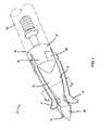
- FIG. 1is a perspective view of an expanding-blade broadhead in accordance with the present invention in which the blades are in a retracted position and with an arrow shaft illustrated in phantom lines;
- FIG. 2is a cross-section taken through lines II—II shown in FIG. 1 ;
- FIG. 3is a detailed perspective view illustrating the ferrule and retaining collar of the present invention.
- FIG. 4is a cross-sectional view of a portion of the ferrule and the retaining collar shown in FIG. 3 ;
- FIG. 5is an exploded side view illustrating the components of the expanding-blade broadhead of the present invention.
- FIG. 6is a partial cross-section illustrating the pivotal connections between the ferrule and the cutting blade
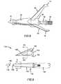
- FIG. 7is a side view of the expanding-blade broadhead shown in a retracted position
- FIG. 8is a side view of the expanding-blade broadhead shown in the deployed position
- FIG. 9is an exploded side view of a fixed-blade broadhead in accordance with the present invention with an arrow shaft illustrated in phantom lines;
- FIG. 10is a cross-sectional view taken through the ferrule portion of the broadhead illustrated in FIG. 9 ;
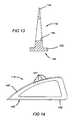
- FIG. 11is an alternate embodiment of a ferrule for the fixed-blade broadhead having a surface texture treatment
- FIG. 12is a cross-sectional view taken through the ferrule portion of the broadhead illustrated in FIG. 11 ;
- FIG. 13is a detailed cross-section view taken through the blade portion of the broadhead illustrated in FIG. 9 showing tapered blade possibilities;
- FIG. 14is an alternate embodiment of the blade for the fixed blade broadhead assembly illustrated in FIG. 9 ;
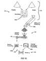
- FIG. 15is a schematic diagram generally illustrating the method of manufacturing components of the broadhead in accordance with the present invention using powdered metallurgy technology.
- FIG. 16is a flow chart illustrating the method of manufacturing the components of the broadhead in accordance with the present invention using powdered metallurgy technology.
- Broadhead 10includes ferrule 12 , cutting blades 14 pivotally coupled to ferrule 12 and collar 16 disposed over an end of ferrule 12 for retaining cutting blades 14 thereon.
- a substantially conical or trocar shaped tip 18is formed at a forward end of ferrule 12 .
- the body 20 of ferrule 12is generally conical or trocar shaped having a triangular cross-section as best seen in FIG. 2 .
- Each of the vertices 22 of body 20has a slot 24 formed therein which receives cutting blade 14 when in the retracted position.
- Ferrule 12further has a base portion 26 having three lugs 28 extending radially from the ferrule.
- a boss 30extends from the radial face 32 of lug 28 .
- Shank 34extends rearwardly from base portion 26 and has a male threaded portion 36 formed at the end thereof for operably coupling broadhead 12 to arrow shaft 38 .
- Cutting blades 14have a cutting edge 40 formed thereon.
- Aperture 42is formed in a bottom portion of cutting blade 14 and is adapted to received receive boss 30 for pivotally coupling cutting blade 14 to ferrule 12 .
- Collar 16is slidably received over shank 34 and has an annular skirt portion 44 with fingers 46 extending longitudinally forward such that fingers 46 are positioned adjacent to lugs 28 formed on ferrule 12 .
- a radial face 48 defined by fingers 46is generally parallel to but spaced apart from radial face 32 to further define slot 24 . As best seen in FIG. 6 a slight clearance is provided between the end of boss 30 and the radial face 48 of finger 46 such that collar 16 may be readily positioned onto ferrule 12 , while at the same time sufficiently retaining cutting blade 14 onto boss 30 .
- broadhead 10is threadedly secured to arrow shaft 38 such that the forward face 50 of arrow shaft 38 pushes retaining collar 16 onto ferrule 12 .
- a compliant element 52is interdisposed between rearward face 54 formed on retaining collar 16 and forward face 50 of arrow shaft 38 to prevent loosening therebetween.
- the overall shape and geometric configuration of the ferrulemay be adapted to various shapes.
- the expanding broadheadmay incorporate more or less cutting blades as the particular application requires.
- the retaining collarmay be secured to the ferrule by other suitable manners.
- the shaft of the ferrulemay be formed of a separate piece from the body of the ferrule.
- some of the components of broadhead 10may be manufactured using a powdered metallurgical manufacturing process resulting in monolithic components.
- the powdered metallurgical processpermits net shape or near net shape parts which have intricate design features.
- the powdered metallurgical processprovides greater control over the shape and weight of the broadhead, and also improves the overall strength of the broadhead.
- the powdered metallurgical processalso eliminates many fabricating and machining steps associated with conventional broadhead manufacturing.
- Broadhead 110includes ferrule 112 , and cutting blades 114 releasably secured to ferrule 112 .
- a conical or trocar shaped tip 118is threadedly secured at a forward end of ferrule 112 and functions to releasably secure cutting blades 114 thereon.
- the body 120 of ferrule 112is generally conically shaped having a triangular cross-section as best seen in FIG. 10 and has a shank 134 extending rearwardly therefrom.
- Each of the vertices 122 of body 120has a T-shaped slot 124 formed therein which releasably secures cutting blades 114 to ferrule 112 .
- Cutting blades 114have a cutting edge 140 formed along the distal edge thereof. As best seen in FIG. 13 , a bead 142 having a profile which compliments T-shaped slot 124 is formed along the proximal edge of cutting blade 114 . A generally triangular aperture 144 is formed in the body of cutting blade 114 to reduce the overall weight of the broadhead and distribute the mass of the blade around its perimeter. As presently preferred, cutting blade 114 has a tapering cross-section from the proximal edge 146 to the distal cutting edge 140 .
- Slot 124is configured to receive the proximal edge 146 of cutting blade 114 including bead 142 .
- Cutting blade 114is slid axially into slots 124 formed in ferrule 112 .
- a threaded shank 148is formed on the back surface of broad tip point 118 and is received in a threaded aperture 152 formed in ferrule 112 . In this way, broadhead tip 118 retains and secures cutting blades 114 with ferrule 112 .
- T-shaped slot configuration and complimentary bead profileis presently preferred, one skilled in the art will recognize that other slot configurations and bead profiles (such as L-shaped, circular, square, etc.) which cooperate to releasably secure blades 114 to ferrule 112 are contemplated by the present invention.
- Broadhead 110may be threadedly secured to arrow shaft 154 in the manner heretofore described.
- a compliant element(not shown) may be interdisposed between ferrule 112 and arrow shaft 154 to prevent loosening therebetween.
- blades 114are releasably secured to ferrule 112 by tip 118 .
- ferrule 112could be configured such that a retaining element disposed over shank 134 or arrow shaft 154 functions to releasably secure blades 114 to ferrule 112 .
- the body 120 ′ of ferrule 112 ′is generally pyramidally shaped having a triangular cross-section as best seen in FIG. 12 .
- Each of the vertices 122 ′ of body 120 ′has a slot 124 ′ formed therein which receives cutting blades 114 .
- the planar surfaces 121 ′ of body 120 ′have a generally textured surface formed thereon for enhancing aerodynamic and penetration properties of the broadhead.
- U.S. Pat. No. 5,871,410discloses a broadhead in which the ferrule has such a textured surface.
- cutting blade 114 ′is generally triangularly configured having a cutting edge 140 ′ formed on a distal edge thereof.
- a plurality of scallops or serrations 141 ′are formed in the cutting edge to further facilitate cutting of the broadhead upon impact.
- Cutting blade 114 ′further includes a bead disposed along a proximal edge thereof for releasably securing blade 114 ′ within ferrule 112 in a manner hereto for described.
- FIGS. 15 and 16a general description of a preferred method of manufacturing a broadhead in accordance with the present invention will now be described. A more detailed description is set forth in U.S. application Ser. No. 09/546,146 filed on Apr. 10, 2000 and entitled “Broadhead and Method Of Manufacture”, the disclosure of which is expressly incorporated by reference herein. The method of manufacture is schematically illustrated in flow chart 100 .
- the manufacturing processis initiated by blending metal powder and binder to form a powdered metal composition as represented at block 102 .
- the metal powder and binderare typically premixed in a first blending step 102 a and then fully mixed to a near homogenous mixture and pelletized in a second blending step 102 b.
- a particular metalsuch as high carbon steel or titanium is mixed with a suitable binder such as a plastic or wax to form a powdered metal composition.
- plastic, ceramic or composite materials suitable for powder injection molding (PIM)may be substituted for the powdered metal composition described above.
- the powdered metal compositionis injected into a broadhead mold 105 having the particular design configurations for fabricating ferrule 12 and collar 16 illustrated in FIGS. 1-8 , or alternately for fabricating ferrule 112 , cutting blade 114 and/or tip 118 .
- a broadhead mold 105having the particular design configurations for fabricating ferrule 12 and collar 16 illustrated in FIGS. 1-8 , or alternately for fabricating ferrule 112 , cutting blade 114 and/or tip 118 .
- the various PIM components of broadhead 110are formed separately.
- the powdered metal compositionis compacted into a greenware broadband component having the precise geometric configuration of the final product (although approximately 20% larger than the end design to account for shrinkage during subsequent processing) and moderate densification (on the order of approximately 50 densification).
- the greenware broadhead componentis processed to eliminate the binder from the metal without melting the constituent metal, thereby forming a powdered metal broadhead component.
- the greenware broadhead componentis immersed in a solvent to separate a portion of the binder from the powdered metal as illustrated in block 106 a.
- the greenware broadhead componentis removed from the solvent and placed in a thermal debinding furnace represented at block 106 b where any remaining binder is burned off.
- the thermal debinding furnacemay also be employed to perform a pre-sintering step. While the debinding steps is described as a combination of chemical and thermal processes, one skilled in the art will readily recognize that any process or combination of processes could be employed to debind the greenware broadhead.
- the powdered metal broadhead componentis still in a moderate densification state.
- the powdered metal broadhead componentis next placed in a sintering furnace and sintered at an elevated temperature and pressure to achieve near full density thereof.
- the sintering processing parametersare defined such that the broadhead reaches a density of at least 97%.
- the overall size of the broadheadshrinks approximately 20%.
- the broadhead componenthas a net shape and does not require further machining.
- the various featuresincluding slots, bosses and threaded shanks are already formed in the ferrule.
- cutting bladesare secured to the ferrule in a final assembly process of the broadhead.
- the broadhead components of the present inventionare fabricated using a powdered metal technology.
- powdered materialssuch as ceramics or plastics may be suitable, and thus utilized herein. The determination of the exact materials are dictated by the requirements of a given application.
Landscapes
- Engineering & Computer Science (AREA)
- General Engineering & Computer Science (AREA)
- Powder Metallurgy (AREA)
Abstract
Description
Claims (12)
Priority Applications (1)
| Application Number | Priority Date | Filing Date | Title |
|---|---|---|---|
| US11/078,917USRE40273E1 (en) | 2000-04-10 | 2005-03-14 | Method of manufacturing an archery broadhead with sintered components |
Applications Claiming Priority (5)
| Application Number | Priority Date | Filing Date | Title |
|---|---|---|---|
| US09/546,146US6290903B1 (en) | 2000-04-10 | 2000-04-10 | Broadhead and method of manufacture |
| US21947400P | 2000-07-20 | 2000-07-20 | |
| US09/910,385US6595881B1 (en) | 2000-04-10 | 2001-07-20 | Expanding-blade archery broadhead |
| US10/360,690US6749801B1 (en) | 2000-04-10 | 2003-02-07 | Method of manufacturing an archery broadhead with sintered components |
| US11/078,917USRE40273E1 (en) | 2000-04-10 | 2005-03-14 | Method of manufacturing an archery broadhead with sintered components |
Related Parent Applications (1)
| Application Number | Title | Priority Date | Filing Date |
|---|---|---|---|
| US10/360,690ReissueUS6749801B1 (en) | 2000-04-10 | 2003-02-07 | Method of manufacturing an archery broadhead with sintered components |
Publications (1)
| Publication Number | Publication Date |
|---|---|
| USRE40273E1true USRE40273E1 (en) | 2008-04-29 |
Family
ID=39321824
Family Applications (1)
| Application Number | Title | Priority Date | Filing Date |
|---|---|---|---|
| US11/078,917Expired - LifetimeUSRE40273E1 (en) | 2000-04-10 | 2005-03-14 | Method of manufacturing an archery broadhead with sintered components |
Country Status (1)
| Country | Link |
|---|---|
| US (1) | USRE40273E1 (en) |
Cited By (5)
| Publication number | Priority date | Publication date | Assignee | Title |
|---|---|---|---|---|
| US8449415B2 (en) | 2010-12-22 | 2013-05-28 | Grace Engineering Corp. | Mechanical broadhead |
| US8449416B2 (en) | 2011-01-11 | 2013-05-28 | Grace Engineering Corp. | Mechanical broadhead |
| US8496549B2 (en) | 2010-07-02 | 2013-07-30 | Gabriel Couture | Arrowhead with improved lethal penetrating capability |
| US10231777B2 (en) | 2014-08-26 | 2019-03-19 | Covidien Lp | Methods of manufacturing jaw members of an end-effector assembly for a surgical instrument |
| US12264904B2 (en) | 2023-08-10 | 2025-04-01 | Bowmar Archery Llc | Variable cutting diameter arrowhead |
Citations (24)
| Publication number | Priority date | Publication date | Assignee | Title |
|---|---|---|---|---|
| US3915455A (en)* | 1974-10-18 | 1975-10-28 | Maurice W Savora | Broadhead arrowtip having a single unit solid body receiving removable very sharp quality cutting blades extending from very nearby the tip to the arrow shaft |
| US4093230A (en)* | 1975-10-06 | 1978-06-06 | New Archery Products Corp. | Arrowhead |
| US4099720A (en)* | 1976-02-23 | 1978-07-11 | Zeren Joseph D | Expanding arrowhead |
| US4166619A (en)* | 1977-03-03 | 1979-09-04 | Bergmann Bruce A | Sequential function hunting arrows |
| US4212464A (en)* | 1978-02-15 | 1980-07-15 | Fansteel Inc. | Dart body |
| US4452460A (en)* | 1982-11-22 | 1984-06-05 | Adams Claude L | Arrowhead construction |
| US4932671A (en)* | 1989-04-03 | 1990-06-12 | Howard P. Anderson, Jr. | Fantom bladed broadhead |
| US4986550A (en)* | 1990-04-19 | 1991-01-22 | Segovia Jose F | Broadhead arrow |
| US5078407A (en)* | 1990-09-12 | 1992-01-07 | Carlston Marvin L | Expandable blade, composite plastic, broadhead hunting arrow tip |
| US5145186A (en)* | 1991-01-04 | 1992-09-08 | Richard Maleski | Broadhead for an arrow and method of securement |
| US5165697A (en)* | 1988-08-30 | 1992-11-24 | Lauriski Stanley E | Broadhead archery hunting point |
| US5203573A (en)* | 1992-05-18 | 1993-04-20 | Michael M. Sakovich | Ballistic arrow tip |
| US5380179A (en)* | 1992-03-16 | 1995-01-10 | Kawasaki Steel Corporation | Binder system for use in the injection molding of sinterable powders and molding compound containing the binder system |
| US5482293A (en)* | 1991-06-05 | 1996-01-09 | Lekavich; Carl W. | Arrowhead |
| US5584845A (en)* | 1994-08-18 | 1996-12-17 | Innovasive Devices, Inc. | Surgical scissor blade and method for making the same |
| US5820498A (en)* | 1996-08-26 | 1998-10-13 | Wasp Archery Products, Inc. | Broadhead for an arrow having expanding cutting blades and method of assembling same |
| USD406305S (en)* | 1997-10-10 | 1999-03-02 | Runde Samuel J | Arrow head |
| US5931751A (en)* | 1997-05-06 | 1999-08-03 | Cooper; Gary L. | Arrowhead |
| US6217467B1 (en)* | 2000-01-03 | 2001-04-17 | Wasp Archery Products, Inc. | Broadhead for an arrow having expanding cutting blades |
| US6290903B1 (en)* | 2000-04-10 | 2001-09-18 | Louis Grace, Jr. | Broadhead and method of manufacture |
| US6322464B1 (en)* | 2000-07-28 | 2001-11-27 | Michael F. Sestak | Hunting arrowhead with broadhead and extendable blades |
| US20020128096A1 (en)* | 2001-03-08 | 2002-09-12 | Philip Muller | Modular broadhead |
| US20030022741A1 (en)* | 2001-01-31 | 2003-01-30 | Philip Muller | Unitary broadhead blade unit |
| US6595881B1 (en)* | 2000-04-10 | 2003-07-22 | Louis Grace, Jr. | Expanding-blade archery broadhead |
- 2005
- 2005-03-14USUS11/078,917patent/USRE40273E1/ennot_activeExpired - Lifetime
Patent Citations (24)
| Publication number | Priority date | Publication date | Assignee | Title |
|---|---|---|---|---|
| US3915455A (en)* | 1974-10-18 | 1975-10-28 | Maurice W Savora | Broadhead arrowtip having a single unit solid body receiving removable very sharp quality cutting blades extending from very nearby the tip to the arrow shaft |
| US4093230A (en)* | 1975-10-06 | 1978-06-06 | New Archery Products Corp. | Arrowhead |
| US4099720A (en)* | 1976-02-23 | 1978-07-11 | Zeren Joseph D | Expanding arrowhead |
| US4166619A (en)* | 1977-03-03 | 1979-09-04 | Bergmann Bruce A | Sequential function hunting arrows |
| US4212464A (en)* | 1978-02-15 | 1980-07-15 | Fansteel Inc. | Dart body |
| US4452460A (en)* | 1982-11-22 | 1984-06-05 | Adams Claude L | Arrowhead construction |
| US5165697A (en)* | 1988-08-30 | 1992-11-24 | Lauriski Stanley E | Broadhead archery hunting point |
| US4932671A (en)* | 1989-04-03 | 1990-06-12 | Howard P. Anderson, Jr. | Fantom bladed broadhead |
| US4986550A (en)* | 1990-04-19 | 1991-01-22 | Segovia Jose F | Broadhead arrow |
| US5078407A (en)* | 1990-09-12 | 1992-01-07 | Carlston Marvin L | Expandable blade, composite plastic, broadhead hunting arrow tip |
| US5145186A (en)* | 1991-01-04 | 1992-09-08 | Richard Maleski | Broadhead for an arrow and method of securement |
| US5482293A (en)* | 1991-06-05 | 1996-01-09 | Lekavich; Carl W. | Arrowhead |
| US5380179A (en)* | 1992-03-16 | 1995-01-10 | Kawasaki Steel Corporation | Binder system for use in the injection molding of sinterable powders and molding compound containing the binder system |
| US5203573A (en)* | 1992-05-18 | 1993-04-20 | Michael M. Sakovich | Ballistic arrow tip |
| US5584845A (en)* | 1994-08-18 | 1996-12-17 | Innovasive Devices, Inc. | Surgical scissor blade and method for making the same |
| US5820498A (en)* | 1996-08-26 | 1998-10-13 | Wasp Archery Products, Inc. | Broadhead for an arrow having expanding cutting blades and method of assembling same |
| US5931751A (en)* | 1997-05-06 | 1999-08-03 | Cooper; Gary L. | Arrowhead |
| USD406305S (en)* | 1997-10-10 | 1999-03-02 | Runde Samuel J | Arrow head |
| US6217467B1 (en)* | 2000-01-03 | 2001-04-17 | Wasp Archery Products, Inc. | Broadhead for an arrow having expanding cutting blades |
| US6290903B1 (en)* | 2000-04-10 | 2001-09-18 | Louis Grace, Jr. | Broadhead and method of manufacture |
| US6595881B1 (en)* | 2000-04-10 | 2003-07-22 | Louis Grace, Jr. | Expanding-blade archery broadhead |
| US6322464B1 (en)* | 2000-07-28 | 2001-11-27 | Michael F. Sestak | Hunting arrowhead with broadhead and extendable blades |
| US20030022741A1 (en)* | 2001-01-31 | 2003-01-30 | Philip Muller | Unitary broadhead blade unit |
| US20020128096A1 (en)* | 2001-03-08 | 2002-09-12 | Philip Muller | Modular broadhead |
Non-Patent Citations (3)
| Title |
|---|
| "An Introduction to Injection Molding Metals & Ceramics", Jun. 1999, pp. 4-5.* |
| "Bowhunting Equipment", 1999 Buyers Guide, p. 70.* |
| Web site Cabela's-http://www.cabelas.com, "BoneBuster Broadheads".* |
Cited By (5)
| Publication number | Priority date | Publication date | Assignee | Title |
|---|---|---|---|---|
| US8496549B2 (en) | 2010-07-02 | 2013-07-30 | Gabriel Couture | Arrowhead with improved lethal penetrating capability |
| US8449415B2 (en) | 2010-12-22 | 2013-05-28 | Grace Engineering Corp. | Mechanical broadhead |
| US8449416B2 (en) | 2011-01-11 | 2013-05-28 | Grace Engineering Corp. | Mechanical broadhead |
| US10231777B2 (en) | 2014-08-26 | 2019-03-19 | Covidien Lp | Methods of manufacturing jaw members of an end-effector assembly for a surgical instrument |
| US12264904B2 (en) | 2023-08-10 | 2025-04-01 | Bowmar Archery Llc | Variable cutting diameter arrowhead |
Similar Documents
| Publication | Publication Date | Title |
|---|---|---|
| US6749801B1 (en) | Method of manufacturing an archery broadhead with sintered components | |
| US6290903B1 (en) | Broadhead and method of manufacture | |
| US6077179A (en) | Arrowhead with a tip having convex facets | |
| US10623808B2 (en) | Broadhead having both deployable and fixed cutting blades | |
| DE69324804T2 (en) | ALL-METAL SHELL BULLET WITH HOLLOW POINT | |
| US7179182B2 (en) | T-lock broadhead and tight point matched balance point archery point system | |
| EP0787969B1 (en) | Manufacturing method for a bullet comprising a core and a jacket | |
| DE102016103818A1 (en) | CUTTING ELEMENT WITH COOLANT FEED | |
| USRE40273E1 (en) | Method of manufacturing an archery broadhead with sintered components | |
| HUE028680T2 (en) | Method of manufacturing variable vane | |
| DE10331397A1 (en) | Production of blade segments for gas turbines comprises using a powder metallurgical injection molding | |
| DE3446578C2 (en) | Radial type ceramic turbine rotor | |
| EP1663554B1 (en) | Method for the production of components of a gas turbine | |
| US6537487B1 (en) | Method of manufacturing form tools for forming threaded fasteners | |
| US7036433B2 (en) | Ammunition projectile having enhanced aerodynamic profile | |
| US6673449B2 (en) | Net molded tantalum carbide rocket nozzle throat and method of making | |
| DE102005019077A1 (en) | Process to modify or manufacture a gas turbine engine blade by attachment of supplementary tip | |
| DE3942744C2 (en) | Process for the production of a ceramic injection molding and its use | |
| DE10343781B4 (en) | Process for the production of components | |
| JPH05288001A (en) | Ceramic gas turbine static blade having cooling hole and its manufacture | |
| DE3942421A1 (en) | CONNECTED CERAMIC BODY | |
| DE102005033625B4 (en) | Method for producing and / or repairing an integrally bladed rotor | |
| US9914171B2 (en) | Manufacturing method | |
| DE69604849T2 (en) | Turbine rotor | |
| WO1999002101A1 (en) | Novel dental curettes |
Legal Events
| Date | Code | Title | Description |
|---|---|---|---|
| AS | Assignment | Owner name:GRACE ENGINEERING CORP., MICHIGAN Free format text:ASSIGNMENT OF ASSIGNORS INTEREST;ASSIGNOR:G5 OUTDOORS, L.L.C.;REEL/FRAME:022052/0563 Effective date:20081230 Owner name:GRACE ENGINEERING CORP.,MICHIGAN Free format text:ASSIGNMENT OF ASSIGNORS INTEREST;ASSIGNOR:G5 OUTDOORS, L.L.C.;REEL/FRAME:022052/0563 Effective date:20081230 | |
| FPAY | Fee payment | Year of fee payment:8 | |
| FPAY | Fee payment | Year of fee payment:12 | |
| AS | Assignment | Owner name:THE HUNTINGTON NATIONAL BANK, MICHIGAN Free format text:SECURITY INTEREST;ASSIGNORS:GRACE ENGINEERING CORP.;G5 OUTDOORS, L.L.C.;GRACE PROPERTIES OF MEMPHIS, L.L.C.;REEL/FRAME:045517/0842 Effective date:20180330 | |
| AS | Assignment | Owner name:GRACE ENGINEERING CORP., MICHIGAN Free format text:RELEASE BY SECURED PARTY;ASSIGNOR:THE HUNTINGTON NATIONAL BANK;REEL/FRAME:071971/0029 Effective date:20250801 Owner name:G5 OUTDOORS, L.L.C., MICHIGAN Free format text:RELEASE BY SECURED PARTY;ASSIGNOR:THE HUNTINGTON NATIONAL BANK;REEL/FRAME:071971/0029 Effective date:20250801 Owner name:GRACE PROPERTIES OF MEMPHIS, L.L.C., MICHIGAN Free format text:RELEASE BY SECURED PARTY;ASSIGNOR:THE HUNTINGTON NATIONAL BANK;REEL/FRAME:071971/0029 Effective date:20250801 |