USRE39721E1 - Discharge outlet for double wall containment tank assembly - Google Patents
Discharge outlet for double wall containment tank assemblyDownload PDFInfo
- Publication number
- USRE39721E1 USRE39721E1US10/717,425US71742503AUSRE39721EUS RE39721 E1USRE39721 E1US RE39721E1US 71742503 AUS71742503 AUS 71742503AUS RE39721 EUSRE39721 EUS RE39721E
- Authority
- US
- United States
- Prior art keywords
- set forth
- containment
- discharge outlet
- tank
- conduit
- Prior art date
- Legal status (The legal status is an assumption and is not a legal conclusion. Google has not performed a legal analysis and makes no representation as to the accuracy of the status listed.)
- Expired - Lifetime
Links
- 238000007789sealingMethods0.000claimsabstractdescription31
- 239000012530fluidSubstances0.000claimsabstract3
- 239000007788liquidSubstances0.000claimsdescription31
- 239000000463materialSubstances0.000claimsdescription6
- 229920003002synthetic resinPolymers0.000claimsdescription6
- 239000000057synthetic resinSubstances0.000claimsdescription6
- 230000008878couplingEffects0.000claims2
- 238000010168coupling processMethods0.000claims2
- 238000005859coupling reactionMethods0.000claims2
- 230000000712assemblyEffects0.000description5
- 238000000429assemblyMethods0.000description5
- 238000010276constructionMethods0.000description3
- 239000000126substanceSubstances0.000description3
- 230000005484gravityEffects0.000description2
- 238000005086pumpingMethods0.000description2
- 239000000523sampleSubstances0.000description2
- 239000004698PolyethyleneSubstances0.000description1
- 230000007797corrosionEffects0.000description1
- 238000005260corrosionMethods0.000description1
- 238000001514detection methodMethods0.000description1
- 230000006866deteriorationEffects0.000description1
- 230000000694effectsEffects0.000description1
- 230000007613environmental effectEffects0.000description1
- 239000000945fillerSubstances0.000description1
- 229920001903high density polyethylenePolymers0.000description1
- 239000004700high-density polyethyleneSubstances0.000description1
- 230000006872improvementEffects0.000description1
- 229920001684low density polyethylenePolymers0.000description1
- 239000004702low-density polyethyleneSubstances0.000description1
- 239000002184metalSubstances0.000description1
- 230000004048modificationEffects0.000description1
- 238000012986modificationMethods0.000description1
- 229920003052natural elastomerPolymers0.000description1
- 229920001194natural rubberPolymers0.000description1
- -1polyethylenePolymers0.000description1
- 229920000573polyethylenePolymers0.000description1
- 229920000915polyvinyl chloridePolymers0.000description1
- 239000004800polyvinyl chlorideSubstances0.000description1
- 230000008439repair processEffects0.000description1
- 229910001220stainless steelInorganic materials0.000description1
- 239000010935stainless steelSubstances0.000description1
- 229920003051synthetic elastomerPolymers0.000description1
- 239000005061synthetic rubberSubstances0.000description1
- 230000007704transitionEffects0.000description1
Images
Classifications
- B—PERFORMING OPERATIONS; TRANSPORTING
- B67—OPENING, CLOSING OR CLEANING BOTTLES, JARS OR SIMILAR CONTAINERS; LIQUID HANDLING
- B67D—DISPENSING, DELIVERING OR TRANSFERRING LIQUIDS, NOT OTHERWISE PROVIDED FOR
- B67D7/00—Apparatus or devices for transferring liquids from bulk storage containers or reservoirs into vehicles or into portable containers, e.g. for retail sale purposes
- B67D7/02—Apparatus or devices for transferring liquids from bulk storage containers or reservoirs into vehicles or into portable containers, e.g. for retail sale purposes for transferring liquids other than fuel or lubricants
- B67D7/0288—Container connection means
- B—PERFORMING OPERATIONS; TRANSPORTING
- B65—CONVEYING; PACKING; STORING; HANDLING THIN OR FILAMENTARY MATERIAL
- B65D—CONTAINERS FOR STORAGE OR TRANSPORT OF ARTICLES OR MATERIALS, e.g. BAGS, BARRELS, BOTTLES, BOXES, CANS, CARTONS, CRATES, DRUMS, JARS, TANKS, HOPPERS, FORWARDING CONTAINERS; ACCESSORIES, CLOSURES, OR FITTINGS THEREFOR; PACKAGING ELEMENTS; PACKAGES
- B65D90/00—Component parts, details or accessories for large containers
- B65D90/22—Safety features
- B65D90/24—Spillage-retaining means, e.g. recovery ponds
Definitions
- This inventionconcerns a discharge outlet for use with a double wall tank assembly used for storing and dispensing large quantities of liquid. More particularly, it is concerned with a sealing boot for the discharge outlet which enables the liquid to be dispensed through openings in the side walls of the inner tank and outer vessel of the double wall tank assembly.
- the present inventioneffectively seals openings provided in the sidewalls of a containment tank assembly having an inner tank and an outer vessel.
- the discharge outletincludes a sealing boot which captures liquid which might leak into the containment area between the inner tank and outer vessel.
- the sealing bootis flexible and thus accommodates relative movement between the inner tank and outer vessel, such as may be encountered by expansion of the inner tank during filling and external forces applied to the outer vessel.
- the discharge outlet of the present inventionbroadly includes an inner tank flange assembly, an outer vessel flange assembly, and a sealing boot interconnecting the two flange assemblies, piping or conduit is preferably provided which extends from the inner flange assembly exteriorly of the outer vessel for attachment of a valve, piping or the like to effect the transfer of liquid from the tank.
- the sealing bootis preferably of a flexible material and is provided in the shape of a tire, whereby liquid leaking may be readily visually detected and repair of the inner tank assembly may be effected without deterioration of the containment capabilities of the double wall tank assembly.
- the piping of the discharge outletwhich is positioned relatively near the bottom of the side of the double wall tank assembly, may be further provided with additional piping interiorly of the inner tank and include a pipe opening near the bottom wall of the inner tank, thereby facilitating removal of most of the liquid within the inner tank when it is desired to be emptied.
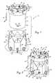
- FIG. 1is a exploded view of a double wall containment tank assembly, showing the opening in the outer vessel for receiving the discharge outlet positioned relatively low on the side thereof;
- FIG. 2is a perspective view of the double wall containment tank assembly shown in FIG. 1 with the inner tank nested in the outer vessel and showing anchor assemblies for holding the double wall containment tank assembly against movement relative to the supporting surface;
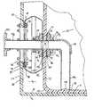
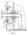
- FIG. 3is an enlarged, vertical sectional view taken through line 3 — 3 of FIG. 2 showing the discharge outlet mounted on the double wall containment tank assembly;
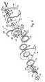
- FIG. 4is an exploded view of the discharge outlet hereof.
- a discharge outlet 10 in accordance with the present inventionis provided for mounting as part of a double wall containment tank assembly 12 used for bulk storage of liquids.
- the double wall containment tank assembly 12includes an inner tank 14 , an outer vessel 16 , and a plurality of anchor assemblies 18 for securing the tank assembly 12 to a pad or other supporting surface 20 .
- the details of the structure of the tank assembly 12are further described in my U.S. Patent Application entitled Containment Tank Assembly filed contemporaneously herewith as application Ser. No. 09/519,323 filed Mar. 6, 2000, the disclosure of which is incorporated herein by reference.
- the inner tank 14includes a lower section 22 , an upper section 24 which extends radially outwardly of lower section 22 and is connected thereto by a lip presenting a trough, and a roof 26 which acts as a cover to define a liquid-receiving chamber 28 therewithin.
- the lipincludes a plurality of circumferentially spaced chutes to permit drainage from the trough back into the interior of the lower section 22 .
- a plurality of upstanding lugs 30project upwardly from the roof 26 for the attachment of cables 32 of anchor assemblies 18 thereto.
- the anchor assemblies 18also include anchors 34 which are bolted into the supporting surface 20 (such as a concrete pad) and connected to the cables 32 by eyebolts 36 .
- a manhole cover 38is interfitted into a manhole in the roof 26 to permit access into the chamber 28 .
- the lugs 30provide pairs of tie-down flanges 40 and lifting flanges 42 , each provided with holes for the passage of cables 32 therethrough.
- An opening through the side of the upper section 24permits the attachment of fill pipe 44 thereto.
- the roof 26receives vent 46 , filler inlet 48 , and level indicator 50 thereon, the latter including a probe for determining the amount of the liquid in the chamber 28 .
- the lower section 22includes a substantially cylindrical sidewall 52 and a bottom wall 58 which are joined at the lower perimeter 60 of the sidewall 52 .
- a port 54is provided in the cylindrical sidewall proximate to the lower perimeter 60 , with four surrounding circumferentially spaced bolt holes 62 provided through the side wall 52 .
- the outer vessel 16includes a multifaceted lower wall portion 64 and a substantially cylindrical upper wall portion 66 .
- the lower wall portion 64includes a plurality of alternating arcuate sections 68 and chord sections 70 .
- the lower wall portion 64tapers inwardly in transition area 72 to cylindrical wall portion 66 , which lies closely adjacent the cylindrical sidewall 52 when the inner tank 14 is nested in the outer tank 16 .
- the upper wall portion 66has an upper margin provided with a plurality of notches 74 for receiving the chutes of the inner tank 14 therein.
- the arcuate sections 68are spaced from the cylindrical sidewall 52 of the inner tank 14 to define therebetween a containment area 76 .
- An access opening 78is provided in one of the arcuate sections 68 for receipt of the discharge outlet 10 therein, with a plurality of surrounding, circumferentially spaced holes 80 for the receipt of the bolts therethrough.
- a leak detection system 82may be mounted in the lower wall portion 64 and include a probe extending downwardly into the containment area 76 to detect the presence of liquid therein.
- the base wall 84connects to the lower wall portion 64 and receives the bottom wall 58 of the inner tank 14 thereon. Both the inner tank 14 and the outer vessel 16 are rotationally molded of synthetic resin, such as high density linear polyethylene or cross-linked, high density polyethylene.
- the discharge outlet 10includes an inner coupler assembly 86 , an coupler flange assembly 88 , sealing boot 90 , and piping 92 .
- the inner coupler assemblyincludes interior flange 94 and intermediate flange 96 which each include a ring 98 and a neck 100 , each flange 94 and 96 having a central opening 102 to permit the flow of liquid therethrough.
- Annular gaskets 104 and 106abut the cylindrical sidewall 52 in sealing relationship thereto.
- the rings 98 and gaskets 104 and 106each include apertures 108 aligned in registry with the bolt holes 62 in the cylindrical sidewall 52 for the receipt of bolts 110 therethrough.
- the bolts 110are secured by suitable nuts and washers.
- the sealing boot 90is located in the containment area 76 and preferably rotationally molded of synthetic resin such as either high density linear or low density polyethylene for flexibility.
- the sealing boot 90is provided in the shape of a tire, including a flat inner wall 112 provided with surrounding, circumferentially spaced apertures 114 for the receipt of bolts 110 therethrough, and a central hole 56 for alignment in registry with the port 54 and the central opening 102 of the neck 100 .
- An circumferentially extending cup-shaped protrusion 116extends radially outwardly from the flat inner wall 112 , with flat outer wall 118 extending radially inwardly therefrom in spaced, opposed relationship to flat inner wall 112 .
- the flat outer wall 118includes an inner margin 120 having a transverse dimension D which is substantially the same as that of the access opening 78 and smaller larger than the diameter of the central hole 56 of the flat inner wall 112 .
- the sealing boot 90thus defines an annular, circumferentially extending channel 122 which permits flexing of the boot 90 and captures liquid leaking past the inner coupler assembly.
- the outer coupler assembly 88has an inner flange provided as semi-annular inner flange plate halves 124 and 126 positioned within the channel 122 , annular gaskets 128 and 130 sandwiching the flat outer wall 118 therebetween, and outer flange plate 132 for engagement against the exterior 134 of the outer vessel.
- the inner flange plate halves 124 and 126 and the outer flange plate 132are preferably stainless steel or other corrosion resistant metal.
- the flat outer wall 118 , inner plate halves 124 and 126 , gaskets 128 and 130 , and outer flange plateinclude holes which are positioned in registry with the holes 80 in the outer vessel 16 for receipt of bolts 136 therethrough.
- the bolts 136are secured in place by suitable nuts and washers as shown in FIGS. 3 and 4 .
- the gaskets 104 and 106 and also 128 and 130are preferably elastomeric, and provided of a chemically resistant natural or synthetic rubber material.
- the piping 92is preferably of a chemical resistant synthetic resin material such as polyvinyl chloride and provides a conduit for the passage of liquid in the chamber 28 out of the containment tank assembly 12 .
- the piping 12includes a discharge tube 138 having an inner end which is preferably chemically welded to the neck 100 of the intermediate flange 96 and an outer end which receives a connection flange 140 for the attachment of further piping or a discharge valve to control the flow of liquid from the chamber 76 .
- An inner tube 142extends into the chamber 76 and has one end which is preferably chemically welded to the neck 100 of interior flange 94 and another end which receives thereon elbow 144 .
- the elbow 144is oriented downwardly and a pickup pipe 146 is connected at one end thereto, the pickup pipe 146 having an open, lower end 148 adjacent the bottom wall for providing an intake into the pipeline 92 for the discharge of liquid therethrough.
- the sealing boot 90 and the access opening 78 of the outer vesselare trimmed to fit with the flange plate halves 124 , 126 and outer flange plate 132 .
- the flange plate halves 124 , 126are placed in the channel 122 with the gaskets positioned as shown in FIG. 3 and the bolts 136 are inserted and tightened.
- the inner tank 14is lowered into the outer vessel 14 in nesting relationship with the chutes received in the inner notches and the port 54 aligned with the access opening 78 .
- the inner tank 14is then preloaded, and the port 54 is trimmed to receive the inner flange assembly 86 .
- the inner tube 142 , elbow 144 and pickup pipe 146are installed into the inner flange assembly 86 mounted on the cylindrical sidewall 52 to permit liquid to flow through the central opening 102 .
- the discharge tube 138 with connection flange 140is then chemically welded to the neck 100 of intermediate flange 96 , and a control valve such as a ball valve or further piping is attached to the connection flange to permit filling of the chamber 28 .
- the discharge outlet 10thus effectively permits the inner tank 14 to be emptied of liquid through gravity rather than pumping, because the integrity of the containment area 76 is preserved by the sealing boot 90 .
- the boot 90is sufficiently flexible to permit limited relative movement between the inner tank 14 and the outer vessel 16 due to seismic events, wind forces or thermal expansion. If liquid begins to leak from the inner tank 14 through the inner flange assembly 86 , the leakage is nonetheless contained within the channel 122 and can be readily visually observed. Other leaking from the inner tank 14 is confined to the containment area 76 between the inner tank 14 and outer vessel 16 , such that even if the leakage rises above the access opening 78 in the side of the outer vessel 16 , it does not escape.
Landscapes
- Engineering & Computer Science (AREA)
- Mechanical Engineering (AREA)
- Details Of Rigid Or Semi-Rigid Containers (AREA)
- Devices For Dispensing Beverages (AREA)
Abstract
Description
Claims (36)
Priority Applications (1)
| Application Number | Priority Date | Filing Date | Title |
|---|---|---|---|
| US10/717,425USRE39721E1 (en) | 2000-03-06 | 2003-11-19 | Discharge outlet for double wall containment tank assembly |
Applications Claiming Priority (2)
| Application Number | Priority Date | Filing Date | Title |
|---|---|---|---|
| US09/519,326US6318581B1 (en) | 2000-03-06 | 2000-03-06 | Discharge outlet for double wall containment tank assembly |
| US10/717,425USRE39721E1 (en) | 2000-03-06 | 2003-11-19 | Discharge outlet for double wall containment tank assembly |
Related Parent Applications (1)
| Application Number | Title | Priority Date | Filing Date |
|---|---|---|---|
| US09/519,326ReissueUS6318581B1 (en) | 2000-03-06 | 2000-03-06 | Discharge outlet for double wall containment tank assembly |
Publications (1)
| Publication Number | Publication Date |
|---|---|
| USRE39721E1true USRE39721E1 (en) | 2007-07-10 |
Family
ID=24067822
Family Applications (2)
| Application Number | Title | Priority Date | Filing Date |
|---|---|---|---|
| US09/519,326CeasedUS6318581B1 (en) | 2000-03-06 | 2000-03-06 | Discharge outlet for double wall containment tank assembly |
| US10/717,425Expired - LifetimeUSRE39721E1 (en) | 2000-03-06 | 2003-11-19 | Discharge outlet for double wall containment tank assembly |
Family Applications Before (1)
| Application Number | Title | Priority Date | Filing Date |
|---|---|---|---|
| US09/519,326CeasedUS6318581B1 (en) | 2000-03-06 | 2000-03-06 | Discharge outlet for double wall containment tank assembly |
Country Status (1)
| Country | Link |
|---|---|
| US (2) | US6318581B1 (en) |
Cited By (5)
| Publication number | Priority date | Publication date | Assignee | Title |
|---|---|---|---|---|
| US20060057008A1 (en)* | 2004-09-10 | 2006-03-16 | Susumu Tauchi | Vacuum processing apparatus |
| US20110315689A1 (en)* | 2010-06-29 | 2011-12-29 | Hoover Materials Handling Group, Inc. | Bulk Packaging Container |
| USD819778S1 (en) | 2014-05-08 | 2018-06-05 | JWF Industries | Vertical fluid storage tank |
| US10202236B2 (en) | 2014-05-06 | 2019-02-12 | JWF Industries | Portable vertical fluid storage tank |
| US11091317B2 (en) | 2014-05-06 | 2021-08-17 | Jwf Industries, Inc. | Vertical fluid storage tank with connecting ports |
Families Citing this family (23)
| Publication number | Priority date | Publication date | Assignee | Title |
|---|---|---|---|---|
| US7080751B2 (en)* | 1998-05-28 | 2006-07-25 | Fernando Alberto Grazziotin | Removable liner coupled to a receptacle for collection of debris |
| US6634676B1 (en)* | 2002-03-13 | 2003-10-21 | Abell Corporation | Rotomolded containment fitting and method of use |
| GB0313581D0 (en)* | 2003-06-12 | 2003-07-16 | Rolls Royce Marine Power Opera | A container for fissile material and a method of making the same |
| US7556059B2 (en)* | 2005-04-27 | 2009-07-07 | Ckd Corporation | Tank structure |
| US20080278041A1 (en)* | 2007-05-10 | 2008-11-13 | The Baker Company | Cable port for biosafety cabinet |
| US20090026212A1 (en)* | 2007-07-25 | 2009-01-29 | Robbins Jess A | Underground storage tank for flammable liquids |
| CA2675482C (en)* | 2009-08-13 | 2014-05-06 | Pearl Point Holdings Ltd. | Tank with containment chamber and separator |
| DE202009012183U1 (en)* | 2009-09-08 | 2009-11-26 | Bürkert Werke GmbH & Co. KG | Manually actuable control module |
| WO2011035429A1 (en)* | 2009-09-22 | 2011-03-31 | Pearl Point Holdings Ltd. | Double walled tanks with internal containment chambers |
| US8915265B2 (en) | 2009-09-22 | 2014-12-23 | Envirovault Corporation | Double walled tanks with internal containment chambers |
| US8276780B2 (en)* | 2009-11-18 | 2012-10-02 | Snyder Industries, Inc. | Fitting torque arm restraint |
| CA2687818C (en)* | 2009-12-10 | 2017-01-03 | Pearl Point Holdings Ltd. | Above-ground storage tanks with internal heat source |
| US8580020B2 (en) | 2010-12-31 | 2013-11-12 | Atterus Holdings Ltd. As Nominee Of Pearl Point Holdings Ltd. | Tank with containment chamber and gas scrubber |
| US20130036588A1 (en)* | 2011-08-09 | 2013-02-14 | Agar Corporation Limited | Method and Apparatus for Installing a Device at a Storage Vessel |
| US9155920B1 (en)* | 2011-10-27 | 2015-10-13 | Flight Suits | Pass-through device for environmental protection suit |
| US9598665B1 (en)* | 2012-07-19 | 2017-03-21 | Thomas A. Barnum | Racking arm tank outlet port |
| US9464745B2 (en)* | 2012-11-01 | 2016-10-11 | Steven Ireland | Large diameter fiberglass tank adapter |
| US20150102038A1 (en)* | 2013-10-16 | 2015-04-16 | Kenneth S. Anderson | Spare Tire Fuel Tank |
| US10254151B2 (en) | 2016-04-08 | 2019-04-09 | Agar Corporation Ltd. | System and method for measuring fluids |
| US10436764B2 (en)* | 2016-12-20 | 2019-10-08 | General Electric Company | System and method for plant fuel quality |
| US10745195B1 (en)* | 2017-08-21 | 2020-08-18 | Murray Services Inc. | Surface mounted secondary containment system |
| US11567059B2 (en) | 2018-12-19 | 2023-01-31 | Agar Corporation, Inc. | Profiler system and method for measuring multiphase fluid |
| TWI704093B (en)* | 2019-05-09 | 2020-09-11 | 辛耘企業股份有限公司 | Treatment liquid container |
Citations (54)
| Publication number | Priority date | Publication date | Assignee | Title |
|---|---|---|---|---|
| US665349A (en) | 1899-06-16 | 1901-01-01 | Thomas Sewall | Insulating-receptacle for holding liquid air. |
| US963454A (en) | 1908-03-19 | 1910-07-05 | Whitall Tatum Co | Sputum-cup and holder therefor. |
| US1330868A (en) | 1915-09-18 | 1920-02-17 | Cleveland Metal Products Co | Cooking utensil |
| US1520230A (en) | 1921-09-19 | 1924-12-23 | Otto S Flath | Storage tank |
| US1544024A (en) | 1921-12-10 | 1925-06-30 | Henry L Moeller | Safety device for tanks containing inflammable liquids |
| US1551007A (en) | 1922-05-10 | 1925-08-25 | Metal Package Corp | Container |
| US1970940A (en) | 1933-05-19 | 1934-08-21 | Laube Charles Joseph | Concrete storage tank with acid-resisting metal linings |
| US1983118A (en) | 1933-07-28 | 1934-12-04 | Bourque Philip | Cooking vessel |
| US2043045A (en) | 1935-05-14 | 1936-06-02 | Emma J Krinard | Cooking utensil |
| US2185026A (en) | 1938-02-16 | 1939-12-26 | Pfaudler Co Inc | Tank and insulating means therefor |
| US2637459A (en) | 1950-12-04 | 1953-05-05 | Olga F Jordan | Double boiler cooking utensil |
| US2777295A (en) | 1952-09-12 | 1957-01-15 | Union Carbide & Carbon Corp | Concrete reservoir for liquefied gases |
| US3069045A (en)* | 1960-01-27 | 1962-12-18 | Union Carbide Corp | Thermally insulated storage container |
| US3111074A (en) | 1961-10-05 | 1963-11-19 | Jr Dwight C Kennard | Evacuation chamber |
| US3125388A (en) | 1964-03-17 | Floor-loading cabinet construction | ||
| US3304852A (en) | 1966-05-31 | 1967-02-21 | Morris M Lande | Beverage making apparatus |
| US3338010A (en) | 1964-12-22 | 1967-08-29 | Chicago Bridge & Iron Co | Insulation foundation for low temperature and cryogenic storage tanks |
| US3352443A (en) | 1965-12-15 | 1967-11-14 | Chicago Bridge & Iron Co | Internal suspended insulating ceiling for storage tanks |
| US3383004A (en) | 1965-08-17 | 1968-05-14 | Preload Co Inc | Plastic storage tank |
| US3473689A (en) | 1967-05-29 | 1969-10-21 | Pittsburgh Des Moines Steel | Insulating foundation |
| US3760972A (en) | 1971-12-10 | 1973-09-25 | Knight Eng & Molding Co | Carafe |
| US3930590A (en) | 1973-12-04 | 1976-01-06 | Shell Oil Company | Storage installation for liquefied gas |
| US4425743A (en) | 1980-11-17 | 1984-01-17 | Joseph Bartur | Inground fluid storage tank and method of erection thereof |
| US4513550A (en) | 1979-06-08 | 1985-04-30 | Technigaz | Method of building a reservoir for storing a liquid at low temperature |
| US4519415A (en) | 1982-05-07 | 1985-05-28 | Chicago Bridge & Iron Company | Liquid storage tank with emergency product removal apparatus |
| US4533062A (en) | 1983-08-11 | 1985-08-06 | Jacob Berg Kg | Container closure for supplying air to or removing air from a container |
| US4584802A (en) | 1982-09-30 | 1986-04-29 | Commissariat A L'energie Atomique | Protective structure for the floor of a concrete enclosure having to contain a high temperature fluid |
| US4651894A (en) | 1984-10-13 | 1987-03-24 | Kennecott Corporation | Jacket system for an enameled or glassed vessel |
| US4697618A (en) | 1985-01-07 | 1987-10-06 | The American Tank & Fabricating Co. | Container structure for dangerous material |
| US4714170A (en) | 1986-04-17 | 1987-12-22 | Trusco Tank Inc. | Large storage tank structures |
| US4840283A (en) | 1987-11-23 | 1989-06-20 | Baker Hughes | Double shell thickener |
| US4865220A (en)* | 1988-07-01 | 1989-09-12 | Owens-Corning Fiberglas Corporation | Double wall tank fittings |
| US4871081A (en) | 1988-01-27 | 1989-10-03 | Ershig's, Inc. | Dual wall vessel for primary and secondary liquid containment |
| US4934553A (en) | 1989-04-03 | 1990-06-19 | Thetacorporation | Above ground waste tank |
| US4960222A (en) | 1989-07-31 | 1990-10-02 | Recontainer, Inc. | Secondary liquid containment system |
| US4976912A (en) | 1986-09-23 | 1990-12-11 | Brennelementlager Gorleben Gmbh | Apparatus for sealing a container for the storage of radioactive material |
| US5033638A (en) | 1990-09-28 | 1991-07-23 | Ecovault Corporation | Above ground hazardous liquid storage apparatus |
| US5056680A (en) | 1987-07-17 | 1991-10-15 | Sharp Bruce R | Attachment assembly for secondary containment tanks |
| US5060815A (en) | 1989-02-05 | 1991-10-29 | Sotralentz S. A. | Transport and storage container for fluent material |
| US5117810A (en) | 1991-11-04 | 1992-06-02 | Aos Holding Company | Apparatus for sealing a foam insulated water heater |
| US5161690A (en) | 1992-01-21 | 1992-11-10 | Dynoplast A/S | Parallellepidepic transport container |
| US5165569A (en) | 1990-07-30 | 1992-11-24 | Sapporo Breweries Ltd. | Keg for draft beer |
| US5201435A (en) | 1991-09-26 | 1993-04-13 | Clawson Tank Company | Storage tank for combustible liquids |
| US5201432A (en) | 1990-10-10 | 1993-04-13 | Elvin Jensen Flemming | Containers |
| US5285922A (en) | 1993-03-29 | 1994-02-15 | Clawson Tank Company | Dual compartment storage tank |
| US5287986A (en) | 1993-02-11 | 1994-02-22 | Abell Corporation | Containment tank assembly |
| US5333752A (en) | 1993-02-18 | 1994-08-02 | Clawson Tank Company | Storage container unit for hazardous liquids |
| US5374026A (en) | 1993-05-17 | 1994-12-20 | Snyder Industries, Inc. | Outlet fitting |
| US5430927A (en) | 1993-07-06 | 1995-07-11 | Snyder Industries, Inc. | Double walled tank and method of making the same |
| US5490603A (en) | 1994-09-06 | 1996-02-13 | Snyder Industries, Inc. | Fluid tank apparatus |
| US5495695A (en) | 1993-01-21 | 1996-03-05 | Dalworth Concrete Products, Inc. | Vaulted underground storage tank |
| US5544974A (en) | 1989-03-01 | 1996-08-13 | Xerxes Corporation | System for underground storage and delivery of liquid product, and recovery of leakage |
| US5544777A (en) | 1991-02-25 | 1996-08-13 | Greif Bros. Corporation | Stackable plastic container with drain sump and pallet and method of making the same |
| US6192940B1 (en)* | 1997-08-20 | 2001-02-27 | Tigers Polymer Corporation | Hoses for electric cleaner |
- 2000
- 2000-03-06USUS09/519,326patent/US6318581B1/ennot_activeCeased
- 2003
- 2003-11-19USUS10/717,425patent/USRE39721E1/ennot_activeExpired - Lifetime
Patent Citations (54)
| Publication number | Priority date | Publication date | Assignee | Title |
|---|---|---|---|---|
| US3125388A (en) | 1964-03-17 | Floor-loading cabinet construction | ||
| US665349A (en) | 1899-06-16 | 1901-01-01 | Thomas Sewall | Insulating-receptacle for holding liquid air. |
| US963454A (en) | 1908-03-19 | 1910-07-05 | Whitall Tatum Co | Sputum-cup and holder therefor. |
| US1330868A (en) | 1915-09-18 | 1920-02-17 | Cleveland Metal Products Co | Cooking utensil |
| US1520230A (en) | 1921-09-19 | 1924-12-23 | Otto S Flath | Storage tank |
| US1544024A (en) | 1921-12-10 | 1925-06-30 | Henry L Moeller | Safety device for tanks containing inflammable liquids |
| US1551007A (en) | 1922-05-10 | 1925-08-25 | Metal Package Corp | Container |
| US1970940A (en) | 1933-05-19 | 1934-08-21 | Laube Charles Joseph | Concrete storage tank with acid-resisting metal linings |
| US1983118A (en) | 1933-07-28 | 1934-12-04 | Bourque Philip | Cooking vessel |
| US2043045A (en) | 1935-05-14 | 1936-06-02 | Emma J Krinard | Cooking utensil |
| US2185026A (en) | 1938-02-16 | 1939-12-26 | Pfaudler Co Inc | Tank and insulating means therefor |
| US2637459A (en) | 1950-12-04 | 1953-05-05 | Olga F Jordan | Double boiler cooking utensil |
| US2777295A (en) | 1952-09-12 | 1957-01-15 | Union Carbide & Carbon Corp | Concrete reservoir for liquefied gases |
| US3069045A (en)* | 1960-01-27 | 1962-12-18 | Union Carbide Corp | Thermally insulated storage container |
| US3111074A (en) | 1961-10-05 | 1963-11-19 | Jr Dwight C Kennard | Evacuation chamber |
| US3338010A (en) | 1964-12-22 | 1967-08-29 | Chicago Bridge & Iron Co | Insulation foundation for low temperature and cryogenic storage tanks |
| US3383004A (en) | 1965-08-17 | 1968-05-14 | Preload Co Inc | Plastic storage tank |
| US3352443A (en) | 1965-12-15 | 1967-11-14 | Chicago Bridge & Iron Co | Internal suspended insulating ceiling for storage tanks |
| US3304852A (en) | 1966-05-31 | 1967-02-21 | Morris M Lande | Beverage making apparatus |
| US3473689A (en) | 1967-05-29 | 1969-10-21 | Pittsburgh Des Moines Steel | Insulating foundation |
| US3760972A (en) | 1971-12-10 | 1973-09-25 | Knight Eng & Molding Co | Carafe |
| US3930590A (en) | 1973-12-04 | 1976-01-06 | Shell Oil Company | Storage installation for liquefied gas |
| US4513550A (en) | 1979-06-08 | 1985-04-30 | Technigaz | Method of building a reservoir for storing a liquid at low temperature |
| US4425743A (en) | 1980-11-17 | 1984-01-17 | Joseph Bartur | Inground fluid storage tank and method of erection thereof |
| US4519415A (en) | 1982-05-07 | 1985-05-28 | Chicago Bridge & Iron Company | Liquid storage tank with emergency product removal apparatus |
| US4584802A (en) | 1982-09-30 | 1986-04-29 | Commissariat A L'energie Atomique | Protective structure for the floor of a concrete enclosure having to contain a high temperature fluid |
| US4533062A (en) | 1983-08-11 | 1985-08-06 | Jacob Berg Kg | Container closure for supplying air to or removing air from a container |
| US4651894A (en) | 1984-10-13 | 1987-03-24 | Kennecott Corporation | Jacket system for an enameled or glassed vessel |
| US4697618A (en) | 1985-01-07 | 1987-10-06 | The American Tank & Fabricating Co. | Container structure for dangerous material |
| US4714170A (en) | 1986-04-17 | 1987-12-22 | Trusco Tank Inc. | Large storage tank structures |
| US4976912A (en) | 1986-09-23 | 1990-12-11 | Brennelementlager Gorleben Gmbh | Apparatus for sealing a container for the storage of radioactive material |
| US5056680A (en) | 1987-07-17 | 1991-10-15 | Sharp Bruce R | Attachment assembly for secondary containment tanks |
| US4840283A (en) | 1987-11-23 | 1989-06-20 | Baker Hughes | Double shell thickener |
| US4871081A (en) | 1988-01-27 | 1989-10-03 | Ershig's, Inc. | Dual wall vessel for primary and secondary liquid containment |
| US4865220A (en)* | 1988-07-01 | 1989-09-12 | Owens-Corning Fiberglas Corporation | Double wall tank fittings |
| US5060815A (en) | 1989-02-05 | 1991-10-29 | Sotralentz S. A. | Transport and storage container for fluent material |
| US5544974A (en) | 1989-03-01 | 1996-08-13 | Xerxes Corporation | System for underground storage and delivery of liquid product, and recovery of leakage |
| US4934553A (en) | 1989-04-03 | 1990-06-19 | Thetacorporation | Above ground waste tank |
| US4960222A (en) | 1989-07-31 | 1990-10-02 | Recontainer, Inc. | Secondary liquid containment system |
| US5165569A (en) | 1990-07-30 | 1992-11-24 | Sapporo Breweries Ltd. | Keg for draft beer |
| US5033638A (en) | 1990-09-28 | 1991-07-23 | Ecovault Corporation | Above ground hazardous liquid storage apparatus |
| US5201432A (en) | 1990-10-10 | 1993-04-13 | Elvin Jensen Flemming | Containers |
| US5544777A (en) | 1991-02-25 | 1996-08-13 | Greif Bros. Corporation | Stackable plastic container with drain sump and pallet and method of making the same |
| US5201435A (en) | 1991-09-26 | 1993-04-13 | Clawson Tank Company | Storage tank for combustible liquids |
| US5117810A (en) | 1991-11-04 | 1992-06-02 | Aos Holding Company | Apparatus for sealing a foam insulated water heater |
| US5161690A (en) | 1992-01-21 | 1992-11-10 | Dynoplast A/S | Parallellepidepic transport container |
| US5495695A (en) | 1993-01-21 | 1996-03-05 | Dalworth Concrete Products, Inc. | Vaulted underground storage tank |
| US5287986A (en) | 1993-02-11 | 1994-02-22 | Abell Corporation | Containment tank assembly |
| US5333752A (en) | 1993-02-18 | 1994-08-02 | Clawson Tank Company | Storage container unit for hazardous liquids |
| US5285922A (en) | 1993-03-29 | 1994-02-15 | Clawson Tank Company | Dual compartment storage tank |
| US5374026A (en) | 1993-05-17 | 1994-12-20 | Snyder Industries, Inc. | Outlet fitting |
| US5430927A (en) | 1993-07-06 | 1995-07-11 | Snyder Industries, Inc. | Double walled tank and method of making the same |
| US5490603A (en) | 1994-09-06 | 1996-02-13 | Snyder Industries, Inc. | Fluid tank apparatus |
| US6192940B1 (en)* | 1997-08-20 | 2001-02-27 | Tigers Polymer Corporation | Hoses for electric cleaner |
Cited By (10)
| Publication number | Priority date | Publication date | Assignee | Title |
|---|---|---|---|---|
| US20060057008A1 (en)* | 2004-09-10 | 2006-03-16 | Susumu Tauchi | Vacuum processing apparatus |
| US7641069B2 (en)* | 2004-09-10 | 2010-01-05 | Hitachi High-Technologies Corporation | Vacuum processing apparatus |
| US20100171061A1 (en)* | 2004-09-10 | 2010-07-08 | Susumu Tauchi | Vacuum processing apparatus |
| US8286822B2 (en) | 2004-09-10 | 2012-10-16 | Hitachi High-Technologies Corporation | Vacuum processing apparatus |
| US8740011B2 (en) | 2004-09-10 | 2014-06-03 | Hitachi High-Technologies Corporation | Vacuum processing apparatus |
| US20110315689A1 (en)* | 2010-06-29 | 2011-12-29 | Hoover Materials Handling Group, Inc. | Bulk Packaging Container |
| US10202236B2 (en) | 2014-05-06 | 2019-02-12 | JWF Industries | Portable vertical fluid storage tank |
| US10494170B2 (en) | 2014-05-06 | 2019-12-03 | JWF Industries | Portable vertical fluid storage tank |
| US11091317B2 (en) | 2014-05-06 | 2021-08-17 | Jwf Industries, Inc. | Vertical fluid storage tank with connecting ports |
| USD819778S1 (en) | 2014-05-08 | 2018-06-05 | JWF Industries | Vertical fluid storage tank |
Also Published As
| Publication number | Publication date |
|---|---|
| US6318581B1 (en) | 2001-11-20 |
Similar Documents
| Publication | Publication Date | Title |
|---|---|---|
| USRE39721E1 (en) | Discharge outlet for double wall containment tank assembly | |
| US4685327A (en) | Total containment storage tank system | |
| US5058633A (en) | Containment assembly for fill pipe of underground storage tanks | |
| US5544974A (en) | System for underground storage and delivery of liquid product, and recovery of leakage | |
| US4639164A (en) | Underground tank sump and piping system | |
| US6029505A (en) | Connecting device for pipe assemblies | |
| US4523454A (en) | External jacket system as secondary containment for storage tanks | |
| US5366318A (en) | Sump assembly | |
| US4884709A (en) | Underground storage tank | |
| US5099894A (en) | Spill containment and flex hose protection device | |
| US8684024B2 (en) | Spill containment system | |
| US4809866A (en) | Spill-containment device | |
| US4912966A (en) | Total containment means for storage tank systems | |
| US6474496B1 (en) | Containment tank assembly | |
| US5505327A (en) | Flexible lined tank with vacuum in the manway | |
| CA2130191A1 (en) | Environmentally safe underground piping system | |
| EP0605713A1 (en) | Sump cover | |
| US4648523A (en) | Underground tank assembly with internal bladder | |
| US5743673A (en) | Watertight sealing system with relief valve for manhole having a spill bucket | |
| US5595456A (en) | Water-tight riser for underground storage tank manway | |
| US20080099490A1 (en) | Flat-sided single-wall attached sump collar | |
| US5397020A (en) | Flexible tank liner with vacuum fitting | |
| US5656766A (en) | Underground drain tank | |
| US5217052A (en) | Containment assembly for fill pipe of underground storage tanks | |
| US5833392A (en) | One-piece tank sump with integral dust cover |
Legal Events
| Date | Code | Title | Description |
|---|---|---|---|
| AS | Assignment | Owner name:CIT LENDING SERVICES CORPORATION, NEW YORK Free format text:ASSIGNMENT FOR SECURITY;ASSIGNOR:SNYDER INDUSTRIES, INC.;REEL/FRAME:017468/0026 Effective date:20051222 | |
| AS | Assignment | Owner name:SNYDER INDUSTRIES, INC., NEBRASKA Free format text:RELEASE BY SECURED PARTY;ASSIGNOR:CIT LENDING SERVICES CORPORATION, AS ADMINISTRATIVE AND COLLATERAL AGENT;REEL/FRAME:021253/0392 Effective date:20080717 Owner name:GENERAL ELECTRIC CAPITAL CORPORATION, AS AGENT, IL Free format text:SECURITY AGREEMENT;ASSIGNOR:SNYDER INDUSTRIES, INC.;REEL/FRAME:021253/0629 Effective date:20080717 | |
| FPAY | Fee payment | Year of fee payment:8 | |
| AS | Assignment | Owner name:SNYDER INDUSTRIES, INC., NEBRASKA Free format text:RELEASE BY SECURED PARTY;ASSIGNOR:GENERAL ELECTRIC CAPITAL CORPORATION, AS AGENT;REEL/FRAME:028517/0129 Effective date:20120709 | |
| AS | Assignment | Owner name:GENERAL ELECTRIC CAPITAL CORPORATION, NEW YORK Free format text:SECURITY AGREEMENT;ASSIGNORS:SNYDER INDUSTRIES, INC.;SNYDER PRODUCTS, LLC;NORWESCO, INC.;REEL/FRAME:028546/0347 Effective date:20120709 | |
| FPAY | Fee payment | Year of fee payment:12 | |
| AS | Assignment | Owner name:ANTARES CAPITAL LP, ILLINOIS Free format text:SECURITY INTEREST;ASSIGNOR:GENERAL ELECTRIC CAPITAL CORPORATION;REEL/FRAME:036420/0265 Effective date:20150821 | |
| AS | Assignment | Owner name:ANTARES CAPITAL LP, AS SUCCESSOR AGENT, ILLINOIS Free format text:CORRECTIVE ASSIGNMENT TO CORRECT THE NATURE OF CONVEYANCE TO ASSIGNMENT OF INTELLECTUAL PROPERTY SECURITY AGREEMENT AND CORRECT CONVEYING AND RECEIVING PARTIES PREVIOUSLY RECORDED ON REEL 036420 FRAME 0265. ASSIGNOR(S) HEREBY CONFIRMS THE ASSIGNMENT OF INTELLECTUAL PROPERTY SECURITY AGREEMENT;ASSIGNOR:GENERAL ELECTRIC CAPITAL CORPORATION, AS RETIRING AGENT;REEL/FRAME:036932/0799 Effective date:20150821 | |
| AS | Assignment | Owner name:SNYDER PRODUCTS, LLC, NEBRASKA Free format text:TERMINATION AND RELEASE OF SECURITY INTEREST IN PATENTS;ASSIGNOR:ANTARES CAPITAL LP, AS AGENT;REEL/FRAME:048705/0642 Effective date:20190326 Owner name:NORWESCO, INC., NEBRASKA Free format text:TERMINATION AND RELEASE OF SECURITY INTEREST IN PATENTS;ASSIGNOR:ANTARES CAPITAL LP, AS AGENT;REEL/FRAME:048705/0642 Effective date:20190326 Owner name:SNYDER INDUSTRIES, INC., NEBRASKA Free format text:TERMINATION AND RELEASE OF SECURITY INTEREST IN PATENTS;ASSIGNOR:ANTARES CAPITAL LP, AS AGENT;REEL/FRAME:048705/0642 Effective date:20190326 | |
| AS | Assignment | Owner name:ANTARES CAPITAL LP, AS COLLATERAL AGENT, ILLINOIS Free format text:GRANT OF SECURITY INTEREST IN PATENT RIGHTS;ASSIGNORS:NORWESCO, LLC;SNYDER INDUSTRIES, LLC;REEL/FRAME:048711/0088 Effective date:20190326 Owner name:ANTARES CAPITAL LP, AS COLLATERAL AGENT, ILLINOIS Free format text:GRANT OF SECURITY INTEREST IN PATENT RIGHTS;ASSIGNORS:NORWESCO, LLC;SNYDER INDUSTRIES, LLC;REEL/FRAME:048711/0141 Effective date:20190326 | |
| AS | Assignment | Owner name:SNYDER INDUSTRIES, LLC, NEBRASKA Free format text:ENTITY CONVERSION;ASSIGNOR:SNYDER INDUSTRIES, INC.;REEL/FRAME:050405/0456 Effective date:20190326 | |
| AS | Assignment | Owner name:TANK HOLDING CORP., NEBRASKA Free format text:CHANGE OF NAME;ASSIGNOR:SNYDER INDUSTRIES, LLC;REEL/FRAME:059458/0806 Effective date:20201223 | |
| AS | Assignment | Owner name:TANK HOLDING CORP., NEBRASKA Free format text:RELEASE BY SECURED PARTY;ASSIGNOR:ANTARES CAPITAL LP, AS COLLATERAL AGENT;REEL/FRAME:059474/0086 Effective date:20220331 Owner name:SNYDER INDUSTRIES, LLC, NEBRASKA Free format text:RELEASE BY SECURED PARTY;ASSIGNOR:ANTARES CAPITAL LP, AS COLLATERAL AGENT;REEL/FRAME:059474/0086 Effective date:20220331 |