USRE39035E1 - Universal coupler for spinal fixation - Google Patents
Universal coupler for spinal fixationDownload PDFInfo
- Publication number
- USRE39035E1 USRE39035E1US08/988,331US98833197AUSRE39035EUS RE39035 E1USRE39035 E1US RE39035E1US 98833197 AUS98833197 AUS 98833197AUS RE39035 EUSRE39035 EUS RE39035E
- Authority
- US
- United States
- Prior art keywords
- coupler
- opening
- openings
- spinal rod
- bore
- Prior art date
- Legal status (The legal status is an assumption and is not a legal conclusion. Google has not performed a legal analysis and makes no representation as to the accuracy of the status listed.)
- Expired - Lifetime
Links
- 210000000988bone and boneAnatomy0.000claimsabstractdescription42
- 238000004873anchoringMethods0.000claims1
- 238000001356surgical procedureMethods0.000description5
- 230000000694effectsEffects0.000description3
- 210000003484anatomyAnatomy0.000description2
- 238000013459approachMethods0.000description2
- 230000000712assemblyEffects0.000description2
- 238000000429assemblyMethods0.000description2
- 239000008280bloodSubstances0.000description2
- 210000004369bloodAnatomy0.000description2
- 206010002091AnaesthesiaDiseases0.000description1
- 230000037005anaesthesiaEffects0.000description1
- 239000000560biocompatible materialSubstances0.000description1
- 230000015572biosynthetic processEffects0.000description1
- 230000006835compressionEffects0.000description1
- 238000007906compressionMethods0.000description1
- 239000007943implantSubstances0.000description1
- 238000002513implantationMethods0.000description1
- 238000012986modificationMethods0.000description1
- 230000004048modificationEffects0.000description1
- 230000000926neurological effectEffects0.000description1
- 210000004872soft tissueAnatomy0.000description1
- 229910001220stainless steelInorganic materials0.000description1
- 239000010935stainless steelSubstances0.000description1
Images

Classifications
- A—HUMAN NECESSITIES
- A61—MEDICAL OR VETERINARY SCIENCE; HYGIENE
- A61B—DIAGNOSIS; SURGERY; IDENTIFICATION
- A61B17/00—Surgical instruments, devices or methods
- A61B17/56—Surgical instruments or methods for treatment of bones or joints; Devices specially adapted therefor
- A61B17/58—Surgical instruments or methods for treatment of bones or joints; Devices specially adapted therefor for osteosynthesis, e.g. bone plates, screws or setting implements
- A61B17/68—Internal fixation devices, including fasteners and spinal fixators, even if a part thereof projects from the skin
- A61B17/70—Spinal positioners or stabilisers, e.g. stabilisers comprising fluid filler in an implant
- A61B17/7001—Screws or hooks combined with longitudinal elements which do not contact vertebrae
- A61B17/7035—Screws or hooks, wherein a rod-clamping part and a bone-anchoring part can pivot relative to each other
- A—HUMAN NECESSITIES
- A61—MEDICAL OR VETERINARY SCIENCE; HYGIENE
- A61B—DIAGNOSIS; SURGERY; IDENTIFICATION
- A61B17/00—Surgical instruments, devices or methods
- A61B17/56—Surgical instruments or methods for treatment of bones or joints; Devices specially adapted therefor
- A61B17/58—Surgical instruments or methods for treatment of bones or joints; Devices specially adapted therefor for osteosynthesis, e.g. bone plates, screws or setting implements
- A61B17/68—Internal fixation devices, including fasteners and spinal fixators, even if a part thereof projects from the skin
- A61B17/70—Spinal positioners or stabilisers, e.g. stabilisers comprising fluid filler in an implant
- A61B17/7001—Screws or hooks combined with longitudinal elements which do not contact vertebrae
- A61B17/7041—Screws or hooks combined with longitudinal elements which do not contact vertebrae with single longitudinal rod offset laterally from single row of screws or hooks
Definitions
- the present inventionrelates to spinal fixation devices, and more particularly, relates to an improved spinal fixation connector that allows for adjustment in four axes of movement when attaching a longitudinal rod to a vertebrae of a spinal column.
- bone screws or boltsare employed in the fixation of the spine wherein the bone screws or bolts are implanted in a surgical procedure involving the formation of one or more surgical openings in adjacent portions of the spine, for implanting the threaded bone bolts or screws into the vertebrae.
- Structuressuch as longitudinal rods or plates extend between the various spine members and are connected to the implanted bone bolts or screws with connector devices.
- Connectors for attaching the rods or plates to vertebrae of a spinal columnare known in the art.
- current bolt to rod connectorsdo not allow for adjustability in multiple planes in order to better conform to the anatomical structure of the patient and to eliminate initial stresses on the spinal fixation construct.
- stressesare put on the component parts of existing spinal fixation systems and on the vertebral column, which are not designed to accommodate stresses much higher than those encountered during normal patient activity.
- the connector of the present inventionallows the entire strength of the connector to be reserved for stresses encountered during patient activity. This provides a spinal construct for a non-compliant patient with activity limitations that is less likely to fail than one with initial high stresses.
- the “single piece” (4 pieces pre-assembled) connector of the present inventionfacilitates rapid assembly during implantation of the fixation construct. This reduces operating time, blood loss and complications which makes the present invention more appealing to surgeons who will spend less time assembling and adjusting spinal fixation constructs in the operating room.
- the present inventionprovides a coupler assembly having four axes of movement for connecting a spinal rod to a vertebrae of a patient with a bone bolt or bone screw.
- the coupler assemblyincludes a tubular coupler member having a longitudinal bore surrounded by a wall.
- the borehas a central axis and first and second end portions with one end being open and internally threaded and the other end portion being closed.
- a plurality of openingsare formed through the wall of the tubular coupler member with each of the openings communicating with the bore.
- the plurality of openingsinclude a first pair of openings aligned along a first line that intersects the central axis of the bore at generally right angles, and a second pair of openings aligned along a second line that intersects the central axis of the bore at generally right angles.
- the first and second pairs of openingsare generally perpendicular to each other and are spaced apart so that the periphery of the first pair of openings is spaced longitudinally from the periphery of the second pair of openings.
- the first pair of openingsis sized and shaped to receive a spinal rod with the spinal rod's longitudinal axis aligning with the first line of the first pair of openings of the coupler body.
- the coupler assemblyalso includes an eyebolt having a shank portion with a central axis and an eye portion.
- the shank portionis insertable through the second pair of openings of the coupler body, with the central axis of the shank aligning with the second line of the second pair of openings.
- the eye portion of the eyebolthas an opening sized and shaped to mate with a selected bone bolt or bone screw.
- An inserthaving an outer surface that generally conforms to the shape of the bore, fits within the bore.
- the inserthas opposed, arc-shaped end portions with recesses for engaging the spinal rod on one end and the eyebolt on the other end.
- a set screwthreadably engages the internally threaded end portion of the bore so that the set screw tightens the assembly of the rod, insert, and eyebolt within the coupler member when tightened down.
- the coupler assembly of the present inventionprovides for movement along four axes that includes a cephalad/caudad direction, a medial/lateral direction, a sagittal plane and transverse plane when the assembly is being implanted in a patient.
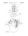
- FIG. 1is a posterior view of a portion of a vertebral column, showing a spinal fixation device connected to the vertebrae by connectors embodying the present invention
- FIG. 2is a partial cross-sectional view taken along sight line 2 — 2 in FIG. 1 , illustrating the manor in which the apparatus of the present invention connect the spinal rods to a vertebrae;
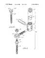
- FIG. 3is a perspective view of the preferred embodiment of the apparatus of the present invention with a spinal rod and bone screw inserted in the apparatus;
- FIG. 4is an exploded perspective view of the preferred embodiment of the apparatus of the present invention.
- FIG. 4Ais a side plan view of an alternate bone fastener
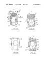
- FIG. 5Ais a side perspective view of the coupler member or the present invention.
- FIG. 5Bis a cross-sectional view taken along sight line 5 B— 5 B in FIG. 5A ;
- FIG. 5Cis a cross-sectional view taken along sight line 5 C— 5 C in FIG. 5A ;
- FIG. 5Dis a side plan view of the coupler member of the present invention.
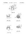
- FIG. 6Ais a side perspective view of the set screw of the apparatus of the present invention.
- FIG. 6Bis a cross-sectional view of the set screw in FIG. 6A ;
- FIG. 7Ais a side perspective view of the insert of the present invention.
- FIG. 7Bis a cross-sectional view taken along sight line 7 B— 7 B in FIG. 7A ;
- FIG. 7Cis a cross-sectional view taken along sight line 7 C— 7 C in FIG. 7A ;
- FIG. 8Ais a side perspective view of the eyebolt of the present invention.
- FIG. 8Bis an end plan view taken along sight line 8 B— 8 B in FIG. 8a ;
- FIG. 8Cis a lower plan view of the eyebolt of the present invention.
- FIG. 8Dis a cross-sectional view taken along sight line 8 D— 8 D in FIG. 8 A.
- FIGS. 1 and 2show the preferred embodiment of the coupler assembly of the present invention, designated generally by the numeral 10 implanted in a spinal column.
- Coupler assembly 10includes a coupler body or member 30 , an eyebolt member 50 , an insert 70 and a set screw 80 , and is used to attach longitudinal rods 12 to a vertebral column 14 comprising a plurality of vertebrae 16 .
- the coupler assembly 10is shown attached to three vertebrae 16 as part of a spinal implant system that is used to hold and stabilize vertebrae 16 . Although the attachment of only three vertebrae 16 is shown, it should be understood that the number of assemblies 10 used can vary such that any number of vertebrae can be held in place.
- Each of the assemblies 10is connected to a respective vertebrae 16 by a fastener 18 which may be either a bone bolt ( FIGS. 2 , 3 , 4 ) or a bone screw 18 A (FIG. 4 A).
- the fastener 18is shown in FIGS. 2 , 3 and 4 as bone bolt 18 having a first threaded end portion 22 for threaded engagement with an opening formed in a pedicle 20 of the vertebrae 16 .
- Bolt 18includes a shoulder portion 24 which establishes how far the first threaded end portion 22 can extend into the vertebrae 16 and spaces the assembly 10 away from the vertebrae 16 .
- Bolt 18has a second threaded end portion 26 extending past the pedicle 20 for engaging the eyebolt 50 of the assembly 10 .
- the bone bolt 18also includes a nut 28 that can be threaded upon the threaded end portion 26 of the bolt 18 to secure eyebolt 50 of assembly 10 against the bolt shoulder 24 .
- Bone screw 18 Aincludes a first threaded end portion 22 A and a head portion 28 A having a spherically shaped lower portion.
- assembly 10is placed over the threaded end portion of 26 of the bolt 18 .
- the nut 28is threaded over the end portion 26 in order to securely fasten the bone bolt 18 to the assembly 10 .
- the longitudinal rod 12having a longitudinal axis A 1 —A 1 ( FIG. 4 ) is placed through an opening in the assembly 10 and the set screw 80 secures the entire assembly 10 A together ( FIGS. 3 , 4 ).
- the coupler assembly 10 Aincludes the coupler assembly 10 , the spinal rod 12 and the bone fastener 18 .
- the assembly 10includes the cylindrical coupler body or member 30 , the eyebolt member 50 , insert 70 , and the set screw 80 that when assembled forms the single piece coupler assembly 10 .
- the coupler body 30is tubular in shape and has a longitudinal bore 32 surrounded by a wall 34 .
- the bore 32has a central axis C 1 and a first or top portion 36 and a second or bottom portion 38 .
- the top portion 36is open-ended and includes internal threading 40 .
- the second or bottom end portion 38is closed.
- the coupler body 30also has an upper portion 36 A and a lower portion 38 A.
- the upper portion 36 A of the coupler body 30has a larger diameter in relation to the lower portion 38 A.
- Coupler body 30includes at least two through openings.
- coupler body 30includes a first pair of openings through wall 34 aligned along a first line L 1 —L 1 that intersects the central axis C 1 of bore 32 at generally right angles ( FIGS. 5A , 5 B).
- Coupler body 30also includes a second pair of openings 44 aligned along a second line L 2 —L 2 that intersects the central axis C 1 of bore 32 at generally right angles ( FIGS. 5A , 5 C).
- Openings 42 and 44are generally perpendicular to each other and spaced apart from each other such that the periphery of the first pair of openings 42 is spaced longitudinally from the periphery of the second pair of openings 44 as shown in FIGS. 3 , 4 and 5 A.
- openings 42are placed in the upper portion 36 A of coupler body 30 and openings 44 are placed in the lower portion 38 A of coupler body 30 .
- Openings 42are sized and shaped to receive the spinal rod 12 with the longitudinal axis A 1 of the rod 12 aligning with the line L 1 —L 1 of the openings 42 when the rod 12 is placed through openings 42 of coupler body 30 (FIG. 3 ). Openings 44 have a lower wall portion 46 which is concave in shape in order to accommodate the cylindrical shank portion of the eyebolt 50 (FIG. 5 B).
- a pair of notches 48are positioned on the outside surface of wall 34 at the open-ended portion 36 of coupler body 30 ( FIGS. 5A , 5 D).
- the notches 48are sized and shaped to accommodate a tool such as a wrench which is used to stabilize the coupler body 30 while the set screw 80 is being tightened into place.
- Eyebolt member 50includes a shank portion 52 and an eye portion 54 (FIG. 8 A).
- Shank portion 52has a central axis C 2 —C 2 and an outer surface 56 (FIG. 8 C).
- shank portion 52is cylindrical in shape with knurling 58 on a portion of the outer surface 56 ( FIGS. 8A , 8 C).
- Shank portion 52includes a shank end 64 with a recess 66 so as to allow slight flanging of shank end 64 after the shank portion 52 is inserted through openings 44 of coupler body 30 ( FIGS. 8B , 8 D). The flanging prevents the shank portion 52 from sliding out of the openings 44 after the coupler assembly 10 has been assembled.
- shank portion 52 of eyebolt 50When shank portion 52 of eyebolt 50 is inserted through openings 44 of coupler body 30 , the shank portion's 52 central axis C 2 —C 2 is aligned along line L 2 —L 2 of openings 44 (FIG. 3 ).
- Eye portion 54 of eyebolt 50includes an opening 60 , an upper surface 61 , and a lower surface 62 .
- Opening 60has a spherically shaped surface 63 on the upper and lower surfaces 61 , 62 of eye portion 54 and is sized and shaped to mate with the fastener 18 .
- the spherically shaped nut 28mates with the spherically shaped surface 63 on the upper surface 61 of the eye portion opening 60 and the spherically shaped shoulder portion 24 mates with the spherically shaped surface 63 on the lower surface 62 of the eye portion opening 60 .
- the bone screw 18 Ais used as the bone fastener instead, the spherically shaped surface of the bone screw head portion 28 A mates with the spherically shaped surface 63 on the upper surface 61 of the eye portion opening.
- Insert 70is cylindrical in shape and has opposed arc-shaped end portions 72 , 76 (FIG. 7 A).
- First end portion 72has a recess 74 that is sized and shaped to engage the spinal rod 12 ( FIGS. 7A , 7 B).
- Second end portion 76has a recess 78 sized and shaped to engage the shank portion 52 of eyebolt 50 ( FIGS. 7A , 7 C).
- Insert 70has an outer surface 71 that generally conforms to the shape of bore 32 of coupler body 30 .
- insert 70is placed in bore 32 after the shank portion 52 of eyebolt 50 has been placed through openings 44 of coupler body 30 .
- Insert 70is placed in bore 32 such that recess 78 contacts the outer surface 56 of shank portion 52 of eyebolt 50 .
- recess 74 of insert 70contacts the surface of the spinal rod 12 .
- insert 70provides greater surface to surface contact between the rod 12 and shank portion 72 then would be possible if the coupler assembly 10 was used without insert 70 .
- Set screw 80has an upper surface 82 , a lower surface 84 , and a threaded body portion 86 that engages and cooperates with the internally threaded end portion 36 of coupler body 30 .
- Upper surface 82is generally flat with a tool receptive socket 88 sized and shaped for receiving a tool designed to thread and tighten the set screw 80 into the threaded portion 40 of bore 32 of coupler body 30 .
- lower surface 84has a smooth outer surface and is generally conical in shape.
- the set screw 80provides means for tightening the rod 12 , insert 70 , and eyebolt 50 within the coupler body 30 .
- the coupler bodycan include a U-shaped top opening, sized and shaped to receive the spinal rod 12 , instead of the pair of openings 42 .
- a cap or a cross-bar with at least one set screwcan be used to tighten the assembly 10 together instead of the set screw 80 .
- Coupler assembly 10is assembled by placing shank portion 52 of eyebolt 50 through openings 44 of coupler body 30 .
- Insert 70is inserted in the bore 32 so as to allow recess 78 to engage the outer surface of shank portion 52 .
- Set screw 80is partially threaded into bore 32 which provides the single piece assembly 10 as shown in FIG. 3 .
- the fastener 18has been implanted in pedicle 20 of vertebrae 16
- the threaded end 26 of bone bolt 18is inserted through the eyebolt opening 60 of coupler assembly 10 .
- Spinal rod 12is inserted through openings 42 such that the spinal rod 12 engages recess 74 of insert 70 .
- set screw 80is tightened into bore 32 of coupler body 30 , securing the entire assembly 10 A in place in the selected position.
- the coupler assembly 10allows for adjustment along four degrees of freedom, as shown in FIG. 3 .
- Assembly 10allows for movement along the longitudinal axis A 1 —A 1 of spinal rod 12 which provides adjustment in a cephalad-caudad direction CC—CC.
- Eyebolt 50can be moved in the openings 44 along the central axis C 2 of shank portion 50 allowing for adjustment in a medial-lateral direction ML—ML.
- the rotation of the spinal rod 12 around its longitudinal axis A 1 —A 1 in the openings 42allows for angulation in a transverse plane TA—TA.
- the rotation of the eyebolt 50 around its central axis C 2 —C 2 in openings 44allows for angulation in a sagittal plane SA—SA.
- the present inventionprovides a “single piece” connector for attaching a spinal rod to a vertebrae that facilitates rapid assembly and allows a wide range of adjustability in four axes of movement.
- the coupler assembly 10is formed of a biocompatible material, and in a preferred embodiment, is formed of stainless steel.
Landscapes
- Health & Medical Sciences (AREA)
- Orthopedic Medicine & Surgery (AREA)
- Life Sciences & Earth Sciences (AREA)
- Neurology (AREA)
- Surgery (AREA)
- Heart & Thoracic Surgery (AREA)
- Engineering & Computer Science (AREA)
- Biomedical Technology (AREA)
- Nuclear Medicine, Radiotherapy & Molecular Imaging (AREA)
- Medical Informatics (AREA)
- Molecular Biology (AREA)
- Animal Behavior & Ethology (AREA)
- General Health & Medical Sciences (AREA)
- Public Health (AREA)
- Veterinary Medicine (AREA)
- Surgical Instruments (AREA)
- Prostheses (AREA)
Abstract
Description
Claims (47)
Priority Applications (1)
| Application Number | Priority Date | Filing Date | Title |
|---|---|---|---|
| US08/988,331USRE39035E1 (en) | 1994-11-18 | 1997-12-11 | Universal coupler for spinal fixation |
Applications Claiming Priority (2)
| Application Number | Priority Date | Filing Date | Title |
|---|---|---|---|
| US08/342,226US5474551A (en) | 1994-11-18 | 1994-11-18 | Universal coupler for spinal fixation |
| US08/988,331USRE39035E1 (en) | 1994-11-18 | 1997-12-11 | Universal coupler for spinal fixation |
Related Parent Applications (1)
| Application Number | Title | Priority Date | Filing Date |
|---|---|---|---|
| US08/342,226ReissueUS5474551A (en) | 1994-11-18 | 1994-11-18 | Universal coupler for spinal fixation |
Publications (1)
| Publication Number | Publication Date |
|---|---|
| USRE39035E1true USRE39035E1 (en) | 2006-03-21 |
Family
ID=23340910
Family Applications (2)
| Application Number | Title | Priority Date | Filing Date |
|---|---|---|---|
| US08/342,226CeasedUS5474551A (en) | 1994-11-18 | 1994-11-18 | Universal coupler for spinal fixation |
| US08/988,331Expired - LifetimeUSRE39035E1 (en) | 1994-11-18 | 1997-12-11 | Universal coupler for spinal fixation |
Family Applications Before (1)
| Application Number | Title | Priority Date | Filing Date |
|---|---|---|---|
| US08/342,226CeasedUS5474551A (en) | 1994-11-18 | 1994-11-18 | Universal coupler for spinal fixation |
Country Status (1)
| Country | Link |
|---|---|
| US (2) | US5474551A (en) |
Cited By (128)
| Publication number | Priority date | Publication date | Assignee | Title |
|---|---|---|---|---|
| US20040133203A1 (en)* | 2002-10-28 | 2004-07-08 | Young J Stewart | Multi-axial, cross-link connector system for spinal implants |
| US20050182410A1 (en)* | 2002-09-06 | 2005-08-18 | Jackson Roger P. | Helical guide and advancement flange with radially loaded lip |
| US20060084979A1 (en)* | 2003-04-09 | 2006-04-20 | Jackson Roger P | Polyaxial bone screw with uploaded threaded shank and method of assembly and use |
| US20060129150A1 (en)* | 2002-09-12 | 2006-06-15 | Showa Ika Kohgyo Co., Ltd. | Rod connector |
| US20060195096A1 (en)* | 2005-02-09 | 2006-08-31 | David Lee | Bone fixation apparatus |
| US20070055244A1 (en)* | 2004-02-27 | 2007-03-08 | Jackson Roger P | Dynamic fixation assemblies with inner core and outer coil-like member |
| US20070156142A1 (en)* | 2005-12-30 | 2007-07-05 | Sdgi Holdings, Inc. | Top-tightening side-locking spinal connector assembly |
| US20070233094A1 (en)* | 2006-03-29 | 2007-10-04 | Dennis Colleran | Dynamic motion spinal stabilization system |
| US20070293861A1 (en)* | 2003-11-24 | 2007-12-20 | Alan Rezach | Grommet assembly |
| US20080039848A1 (en)* | 2002-09-06 | 2008-02-14 | Jackson Roger P | Anti-splay medical implant closure with multi-surface removal aperture |
| US20080047914A1 (en)* | 2006-05-19 | 2008-02-28 | Young International Llc | Shelving system |
| RU2321371C1 (en)* | 2006-07-14 | 2008-04-10 | Научно-исследовательский центр Татарстана "Восстановительная травматология и ортопедия" | Reposition spinal column lock |
| US20080188898A1 (en)* | 2004-11-23 | 2008-08-07 | Jackson Roger P | Polyaxial bone screw with multi-part shank retainer and pressure insert |
| US20080234757A1 (en)* | 2007-02-27 | 2008-09-25 | Jacofsky Marc C | Modular pedicle screw system |
| RU2335256C2 (en)* | 2006-10-06 | 2008-10-10 | Государственное унитарное предприятие Республики Татарстан "Всероссийский научно-исследовательский проектный институт медицинских инструментов" (ГУП РТ ВНИПИМИ) | Device for treatment of spine fractures |
| US20080262556A1 (en)* | 2007-02-27 | 2008-10-23 | Jacofsky Marc C | Modular polyaxial pedicle screw system |
| US20090062858A1 (en)* | 2007-08-31 | 2009-03-05 | Sara Dziedzic | Methods and instruments for approximating misaligned |
| US20090062864A1 (en)* | 2007-08-31 | 2009-03-05 | Steven Ludwig | Offset connection bone anchor assembly |
| US20090062822A1 (en)* | 2007-08-31 | 2009-03-05 | Frasier William J | Adaptable clamping mechanism for coupling a spinal fixation element to a bone anchor |
| US20090062859A1 (en)* | 2007-08-31 | 2009-03-05 | Michael Mahoney | Method and system for securing a rod to a bone anchor with a connector |
| US20090076550A1 (en)* | 2007-09-18 | 2009-03-19 | Ortho Development Corporation | Spinal fixation system connectors |
| RU2369351C1 (en)* | 2008-04-04 | 2009-10-10 | Государственное учреждение "Научно-исследовательский центр Татарстана "Восстановительная травматология и ортопедия" | Repositional spine holder |
| US20100004696A1 (en)* | 2004-02-27 | 2010-01-07 | Jackson Roger P | Orthopedic implant rod reduction tool set and method |
| US7662175B2 (en) | 2003-06-18 | 2010-02-16 | Jackson Roger P | Upload shank swivel head bone screw spinal implant |
| US20100049252A1 (en)* | 2008-08-21 | 2010-02-25 | Southern Spine, Llc | Transverse Connector Device for Extending an Existing Spinal Fixation System |
| US20100125302A1 (en)* | 2008-11-14 | 2010-05-20 | Hammill Sr John E | Locking Polyaxial Ball And Socket Fastener |
| US7736380B2 (en) | 2004-12-21 | 2010-06-15 | Rhausler, Inc. | Cervical plate system |
| US20100234893A1 (en)* | 2009-03-10 | 2010-09-16 | Andrew Iott | Spinal Implant Connection Assembly |
| US7854752B2 (en) | 2004-08-09 | 2010-12-21 | Theken Spine, Llc | System and method for dynamic skeletal stabilization |
| US7901437B2 (en) | 2007-01-26 | 2011-03-08 | Jackson Roger P | Dynamic stabilization member with molded connection |
| US20110106164A1 (en)* | 2009-10-30 | 2011-05-05 | Warsaw Othropedic, Inc. | Apparatus for implementing a spinal fixation system with supplemental fixation |
| US7942911B2 (en) | 2007-05-16 | 2011-05-17 | Ortho Innovations, Llc | Polyaxial bone screw |
| US7942909B2 (en) | 2009-08-13 | 2011-05-17 | Ortho Innovations, Llc | Thread-thru polyaxial pedicle screw system |
| US7942910B2 (en) | 2007-05-16 | 2011-05-17 | Ortho Innovations, Llc | Polyaxial bone screw |
| US7951173B2 (en) | 2007-05-16 | 2011-05-31 | Ortho Innovations, Llc | Pedicle screw implant system |
| US7951170B2 (en) | 2007-05-31 | 2011-05-31 | Jackson Roger P | Dynamic stabilization connecting member with pre-tensioned solid core |
| US7967850B2 (en) | 2003-06-18 | 2011-06-28 | Jackson Roger P | Polyaxial bone anchor with helical capture connection, insert and dual locking assembly |
| US20110196425A1 (en)* | 2010-02-05 | 2011-08-11 | Warsaw Orthopedic, Inc. | Connector and Method |
| US8012177B2 (en) | 2007-02-12 | 2011-09-06 | Jackson Roger P | Dynamic stabilization assembly with frusto-conical connection |
| US8057518B2 (en) | 2007-08-31 | 2011-11-15 | Depuy Spine, Inc. | Spanning connector for connecting a spinal fixation element and an offset bone anchor |
| US8066739B2 (en) | 2004-02-27 | 2011-11-29 | Jackson Roger P | Tool system for dynamic spinal implants |
| US8075603B2 (en) | 2008-11-14 | 2011-12-13 | Ortho Innovations, Llc | Locking polyaxial ball and socket fastener |
| US8092500B2 (en) | 2007-05-01 | 2012-01-10 | Jackson Roger P | Dynamic stabilization connecting member with floating core, compression spacer and over-mold |
| US8105368B2 (en) | 2005-09-30 | 2012-01-31 | Jackson Roger P | Dynamic stabilization connecting member with slitted core and outer sleeve |
| US8137386B2 (en) | 2003-08-28 | 2012-03-20 | Jackson Roger P | Polyaxial bone screw apparatus |
| US8152810B2 (en) | 2004-11-23 | 2012-04-10 | Jackson Roger P | Spinal fixation tool set and method |
| US20120109209A1 (en)* | 2010-10-29 | 2012-05-03 | Warsaw Orthopedic, Inc. | Spinal Connector Assembly |
| US8197518B2 (en) | 2007-05-16 | 2012-06-12 | Ortho Innovations, Llc | Thread-thru polyaxial pedicle screw system |
| US8257402B2 (en) | 2002-09-06 | 2012-09-04 | Jackson Roger P | Closure for rod receiving orthopedic implant having left handed thread removal |
| US8257398B2 (en) | 2003-06-18 | 2012-09-04 | Jackson Roger P | Polyaxial bone screw with cam capture |
| US8273109B2 (en) | 2002-09-06 | 2012-09-25 | Jackson Roger P | Helical wound mechanically interlocking mating guide and advancement structure |
| US8292926B2 (en) | 2005-09-30 | 2012-10-23 | Jackson Roger P | Dynamic stabilization connecting member with elastic core and outer sleeve |
| US8308782B2 (en) | 2004-11-23 | 2012-11-13 | Jackson Roger P | Bone anchors with longitudinal connecting member engaging inserts and closures for fixation and optional angulation |
| US8313515B2 (en) | 2007-06-15 | 2012-11-20 | Rachiotek, Llc | Multi-level spinal stabilization system |
| US8343152B2 (en) | 2008-08-07 | 2013-01-01 | Toby Orthopaedics, Inc. | Fixed angle dual prong pin fixation system |
| US8353932B2 (en) | 2005-09-30 | 2013-01-15 | Jackson Roger P | Polyaxial bone anchor assembly with one-piece closure, pressure insert and plastic elongate member |
| US8366745B2 (en) | 2007-05-01 | 2013-02-05 | Jackson Roger P | Dynamic stabilization assembly having pre-compressed spacers with differential displacements |
| US8366753B2 (en) | 2003-06-18 | 2013-02-05 | Jackson Roger P | Polyaxial bone screw assembly with fixed retaining structure |
| US8377100B2 (en) | 2000-12-08 | 2013-02-19 | Roger P. Jackson | Closure for open-headed medical implant |
| US8377102B2 (en) | 2003-06-18 | 2013-02-19 | Roger P. Jackson | Polyaxial bone anchor with spline capture connection and lower pressure insert |
| US8398682B2 (en) | 2003-06-18 | 2013-03-19 | Roger P. Jackson | Polyaxial bone screw assembly |
| US8444681B2 (en) | 2009-06-15 | 2013-05-21 | Roger P. Jackson | Polyaxial bone anchor with pop-on shank, friction fit retainer and winged insert |
| US8475498B2 (en) | 2007-01-18 | 2013-07-02 | Roger P. Jackson | Dynamic stabilization connecting member with cord connection |
| US8545538B2 (en) | 2005-12-19 | 2013-10-01 | M. Samy Abdou | Devices and methods for inter-vertebral orthopedic device placement |
| US8556938B2 (en) | 2009-06-15 | 2013-10-15 | Roger P. Jackson | Polyaxial bone anchor with non-pivotable retainer and pop-on shank, some with friction fit |
| US8591515B2 (en) | 2004-11-23 | 2013-11-26 | Roger P. Jackson | Spinal fixation tool set and method |
| US8657856B2 (en) | 2009-08-28 | 2014-02-25 | Pioneer Surgical Technology, Inc. | Size transition spinal rod |
| US8814913B2 (en) | 2002-09-06 | 2014-08-26 | Roger P Jackson | Helical guide and advancement flange with break-off extensions |
| US8814911B2 (en) | 2003-06-18 | 2014-08-26 | Roger P. Jackson | Polyaxial bone screw with cam connection and lock and release insert |
| US8845649B2 (en) | 2004-09-24 | 2014-09-30 | Roger P. Jackson | Spinal fixation tool set and method for rod reduction and fastener insertion |
| US8852239B2 (en) | 2013-02-15 | 2014-10-07 | Roger P Jackson | Sagittal angle screw with integral shank and receiver |
| US8900237B2 (en) | 2007-08-31 | 2014-12-02 | DePuy Synthes Products, LLC | Minimally invasive guide system |
| US8911477B2 (en) | 2007-10-23 | 2014-12-16 | Roger P. Jackson | Dynamic stabilization member with end plate support and cable core extension |
| US8911479B2 (en) | 2012-01-10 | 2014-12-16 | Roger P. Jackson | Multi-start closures for open implants |
| US8911478B2 (en) | 2012-11-21 | 2014-12-16 | Roger P. Jackson | Splay control closure for open bone anchor |
| US8926670B2 (en) | 2003-06-18 | 2015-01-06 | Roger P. Jackson | Polyaxial bone screw assembly |
| US8926672B2 (en) | 2004-11-10 | 2015-01-06 | Roger P. Jackson | Splay control closure for open bone anchor |
| US8979904B2 (en) | 2007-05-01 | 2015-03-17 | Roger P Jackson | Connecting member with tensioned cord, low profile rigid sleeve and spacer with torsion control |
| US8998960B2 (en) | 2004-11-10 | 2015-04-07 | Roger P. Jackson | Polyaxial bone screw with helically wound capture connection |
| US8998959B2 (en) | 2009-06-15 | 2015-04-07 | Roger P Jackson | Polyaxial bone anchors with pop-on shank, fully constrained friction fit retainer and lock and release insert |
| US9050139B2 (en) | 2004-02-27 | 2015-06-09 | Roger P. Jackson | Orthopedic implant rod reduction tool set and method |
| US9168069B2 (en) | 2009-06-15 | 2015-10-27 | Roger P. Jackson | Polyaxial bone anchor with pop-on shank and winged insert with lower skirt for engaging a friction fit retainer |
| US9198695B2 (en) | 2010-08-30 | 2015-12-01 | Zimmer Spine, Inc. | Polyaxial pedicle screw |
| US9216039B2 (en) | 2004-02-27 | 2015-12-22 | Roger P. Jackson | Dynamic spinal stabilization assemblies, tool set and method |
| US9216041B2 (en) | 2009-06-15 | 2015-12-22 | Roger P. Jackson | Spinal connecting members with tensioned cords and rigid sleeves for engaging compression inserts |
| US9247962B2 (en) | 2011-08-15 | 2016-02-02 | K2M, Inc. | Laminar hook insertion device |
| US9308027B2 (en) | 2005-05-27 | 2016-04-12 | Roger P Jackson | Polyaxial bone screw with shank articulation pressure insert and method |
| US9414863B2 (en) | 2005-02-22 | 2016-08-16 | Roger P. Jackson | Polyaxial bone screw with spherical capture, compression insert and alignment and retention structures |
| US9451993B2 (en) | 2014-01-09 | 2016-09-27 | Roger P. Jackson | Bi-radial pop-on cervical bone anchor |
| US9453526B2 (en) | 2013-04-30 | 2016-09-27 | Degen Medical, Inc. | Bottom-loading anchor assembly |
| US9451989B2 (en) | 2007-01-18 | 2016-09-27 | Roger P Jackson | Dynamic stabilization members with elastic and inelastic sections |
| US9480517B2 (en) | 2009-06-15 | 2016-11-01 | Roger P. Jackson | Polyaxial bone anchor with pop-on shank, shank, friction fit retainer, winged insert and low profile edge lock |
| US9566092B2 (en) | 2013-10-29 | 2017-02-14 | Roger P. Jackson | Cervical bone anchor with collet retainer and outer locking sleeve |
| US9597119B2 (en) | 2014-06-04 | 2017-03-21 | Roger P. Jackson | Polyaxial bone anchor with polymer sleeve |
| US9668771B2 (en) | 2009-06-15 | 2017-06-06 | Roger P Jackson | Soft stabilization assemblies with off-set connector |
| US9717533B2 (en) | 2013-12-12 | 2017-08-01 | Roger P. Jackson | Bone anchor closure pivot-splay control flange form guide and advancement structure |
| US9839492B2 (en)* | 2013-09-05 | 2017-12-12 | Heriberto Bujanda Wong | Ultrasonic ring tip to activate endodontic instruments |
| US9907574B2 (en) | 2008-08-01 | 2018-03-06 | Roger P. Jackson | Polyaxial bone anchors with pop-on shank, friction fit fully restrained retainer, insert and tool receiving features |
| US9980753B2 (en) | 2009-06-15 | 2018-05-29 | Roger P Jackson | pivotal anchor with snap-in-place insert having rotation blocking extensions |
| US10039578B2 (en) | 2003-12-16 | 2018-08-07 | DePuy Synthes Products, Inc. | Methods and devices for minimally invasive spinal fixation element placement |
| US10058354B2 (en) | 2013-01-28 | 2018-08-28 | Roger P. Jackson | Pivotal bone anchor assembly with frictional shank head seating surfaces |
| US10064658B2 (en) | 2014-06-04 | 2018-09-04 | Roger P. Jackson | Polyaxial bone anchor with insert guides |
| US10194951B2 (en) | 2005-05-10 | 2019-02-05 | Roger P. Jackson | Polyaxial bone anchor with compound articulation and pop-on shank |
| US10258382B2 (en) | 2007-01-18 | 2019-04-16 | Roger P. Jackson | Rod-cord dynamic connection assemblies with slidable bone anchor attachment members along the cord |
| US10278741B2 (en) | 2013-10-07 | 2019-05-07 | Spine Wave, Inc. | Translating polyaxial screw |
| US10299839B2 (en) | 2003-12-16 | 2019-05-28 | Medos International Sárl | Percutaneous access devices and bone anchor assemblies |
| US10349983B2 (en) | 2003-05-22 | 2019-07-16 | Alphatec Spine, Inc. | Pivotal bone anchor assembly with biased bushing for pre-lock friction fit |
| US10363070B2 (en) | 2009-06-15 | 2019-07-30 | Roger P. Jackson | Pivotal bone anchor assemblies with pressure inserts and snap on articulating retainers |
| US10383660B2 (en) | 2007-05-01 | 2019-08-20 | Roger P. Jackson | Soft stabilization assemblies with pretensioned cords |
| US10485588B2 (en) | 2004-02-27 | 2019-11-26 | Nuvasive, Inc. | Spinal fixation tool attachment structure |
| US10543107B2 (en) | 2009-12-07 | 2020-01-28 | Samy Abdou | Devices and methods for minimally invasive spinal stabilization and instrumentation |
| US10548740B1 (en) | 2016-10-25 | 2020-02-04 | Samy Abdou | Devices and methods for vertebral bone realignment |
| US10575961B1 (en) | 2011-09-23 | 2020-03-03 | Samy Abdou | Spinal fixation devices and methods of use |
| US10695105B2 (en) | 2012-08-28 | 2020-06-30 | Samy Abdou | Spinal fixation devices and methods of use |
| US10716596B2 (en) | 2017-10-10 | 2020-07-21 | Spine Wave, Inc. | Translational posterior cervical polyaxial screw |
| US10722276B2 (en) | 2013-03-14 | 2020-07-28 | K2M, Inc. | Taper lock hook |
| US10722271B2 (en) | 2014-02-20 | 2020-07-28 | K2M, Inc. | Spinal fixation device |
| US10729469B2 (en) | 2006-01-09 | 2020-08-04 | Roger P. Jackson | Flexible spinal stabilization assembly with spacer having off-axis core member |
| US10857003B1 (en) | 2015-10-14 | 2020-12-08 | Samy Abdou | Devices and methods for vertebral stabilization |
| US10918498B2 (en) | 2004-11-24 | 2021-02-16 | Samy Abdou | Devices and methods for inter-vertebral orthopedic device placement |
| US10973648B1 (en) | 2016-10-25 | 2021-04-13 | Samy Abdou | Devices and methods for vertebral bone realignment |
| US11006982B2 (en) | 2012-02-22 | 2021-05-18 | Samy Abdou | Spinous process fixation devices and methods of use |
| US11173040B2 (en) | 2012-10-22 | 2021-11-16 | Cogent Spine, LLC | Devices and methods for spinal stabilization and instrumentation |
| US11179248B2 (en) | 2018-10-02 | 2021-11-23 | Samy Abdou | Devices and methods for spinal implantation |
| US11229457B2 (en) | 2009-06-15 | 2022-01-25 | Roger P. Jackson | Pivotal bone anchor assembly with insert tool deployment |
| US11241261B2 (en) | 2005-09-30 | 2022-02-08 | Roger P Jackson | Apparatus and method for soft spinal stabilization using a tensionable cord and releasable end structure |
| US11419642B2 (en) | 2003-12-16 | 2022-08-23 | Medos International Sarl | Percutaneous access devices and bone anchor assemblies |
| US12383311B2 (en) | 2010-05-14 | 2025-08-12 | Roger P. Jackson | Pivotal bone anchor assembly and method for use thereof |
Families Citing this family (156)
| Publication number | Priority date | Publication date | Assignee | Title |
|---|---|---|---|---|
| WO1998008454A1 (en)* | 1994-05-25 | 1998-03-05 | Jackson Roger P | Apparatus and method for spinal fixation and correction of spinal deformities |
| US6004322A (en)* | 1994-10-25 | 1999-12-21 | Sdgi Holdings, Inc. | Modular pedicle screw system |
| US6176861B1 (en) | 1994-10-25 | 2001-01-23 | Sdgi Holdings, Inc. | Modular spinal system |
| AU2101495A (en)* | 1995-03-13 | 1996-10-02 | Steven D. Gelbard | Spinal stabilization implant system |
| US5645544A (en)* | 1995-09-13 | 1997-07-08 | Danek Medical, Inc. | Variable angle extension rod |
| FR2742040B1 (en)* | 1995-12-07 | 1998-01-23 | Groupe Lepine | ASSEMBLY DEVICE FOR EXTENDED PARTS OF OSTEOSYNTHESIS MATERIAL, ESPECIALLY SPINAL |
| EP0873090A1 (en)* | 1995-12-22 | 1998-10-28 | Ohio Medical Instrument Company, Inc. | Spinal fixation device with laterally attachable connectors |
| US5669910A (en)* | 1996-01-02 | 1997-09-23 | Pioneer Laboratories, Inc. | Crosslink for implantable rods |
| US5741255A (en)* | 1996-06-05 | 1998-04-21 | Acromed Corporation | Spinal column retaining apparatus |
| ES2191775T3 (en)* | 1996-12-12 | 2003-09-16 | Synthes Ag | DEVICE FOR CONNECTING A LONGITUDINAL SUPPORT WITH A PEDICULAR SCREW. |
| US5776135A (en)* | 1996-12-23 | 1998-07-07 | Third Millennium Engineering, Llc | Side mounted polyaxial pedicle screw |
| US6371957B1 (en) | 1997-01-22 | 2002-04-16 | Synthes (Usa) | Device for connecting a longitudinal bar to a pedicle screw |
| FR2761590B1 (en)* | 1997-04-04 | 1999-08-20 | Stryker France Sa | DEVICE FOR OSTEOSYNTHESIS OF THE RACHIS WITH ATTACHMENT OF DEAXED INTERVERTEBRAL ROD |
| US5785711A (en)* | 1997-05-15 | 1998-07-28 | Third Millennium Engineering, Llc | Polyaxial pedicle screw having a through bar clamp locking mechanism |
| US6413257B1 (en)* | 1997-05-15 | 2002-07-02 | Surgical Dynamics, Inc. | Clamping connector for spinal fixation systems |
| US6248105B1 (en) | 1997-05-17 | 2001-06-19 | Synthes (U.S.A.) | Device for connecting a longitudinal support with a pedicle screw |
| ES2133233B1 (en)* | 1997-05-20 | 2000-02-16 | Mecanizados Y Talleres Ind S A | RING FOR THE PEDICULAR SCREWING OF RINGED BARS IN THE INSTRUCTION OF THE RACHIS. |
| IES77331B2 (en)* | 1997-06-03 | 1997-12-03 | Tecos Holdings Inc | Pluridirectional and modulable vertebral osteosynthesis device of small overall size |
| AU3764597A (en)* | 1997-08-21 | 1999-03-16 | Synthes Ag, Chur | Device for connecting a rod to another implant |
| US5976135A (en)* | 1997-12-18 | 1999-11-02 | Sdgi Holdings, Inc. | Lateral connector assembly |
| US6325803B1 (en) | 1998-02-18 | 2001-12-04 | Walter Lorenz Surgical, Inc. | Method and apparatus for mandibular osteosynthesis |
| US7052499B2 (en)* | 1998-02-18 | 2006-05-30 | Walter Lorenz Surgical, Inc. | Method and apparatus for bone fracture fixation |
| US6129728A (en)* | 1998-02-18 | 2000-10-10 | Walter Lorenz Surgical, Inc. | Method and apparatus for mandibular osteosynthesis |
| US6179838B1 (en) | 1998-02-24 | 2001-01-30 | Daniel Fiz | Bone fixation arrangements and method |
| FR2776500B1 (en)* | 1998-03-31 | 2000-09-29 | Bianchi | CONNECTION DEVICE FOR OSTEOSYNTHESIS |
| US6083226A (en)* | 1998-04-22 | 2000-07-04 | Fiz; Daniel | Bone fixation device and transverse linking bridge |
| FR2781663B1 (en) | 1998-07-30 | 2000-10-13 | Materiel Orthopedique En Abreg | SPINAL OSTEOSYNTHESIS DEVICE |
| WO2000015125A1 (en) | 1998-09-11 | 2000-03-23 | Synthes Ag Chur | Variable angle spinal fixation system |
| US5984924A (en)* | 1998-10-07 | 1999-11-16 | Isola Implants, Inc. | Bone alignment system having variable orientation bone anchors |
| WO2000037715A1 (en) | 1998-11-18 | 2000-06-29 | The Johns Hopkins University | Bismuth thin film structure and method of construction |
| KR100324698B1 (en)* | 1999-01-30 | 2002-02-27 | 구자교 | Spine fixing device |
| US6328739B1 (en) | 1999-05-04 | 2001-12-11 | Industrial Technology Research Institute | Enhanced spine fixation apparatus |
| FR2796546B1 (en)* | 1999-07-23 | 2001-11-30 | Eurosurgical | POLYAXIAL CONNECTOR FOR SPINAL IMPLANT |
| AU6633900A (en) | 1999-08-12 | 2001-03-13 | Osteotech, Inc. | Rod-to-rod coupler |
| US6530929B1 (en) | 1999-10-20 | 2003-03-11 | Sdgi Holdings, Inc. | Instruments for stabilization of bony structures |
| US7674293B2 (en) | 2004-04-22 | 2010-03-09 | Facet Solutions, Inc. | Crossbar spinal prosthesis having a modular design and related implantation methods |
| ATE285207T1 (en) | 1999-10-22 | 2005-01-15 | Archus Orthopedics Inc | FACET ARTHROPLASTY DEVICES |
| US7691145B2 (en) | 1999-10-22 | 2010-04-06 | Facet Solutions, Inc. | Prostheses, systems and methods for replacement of natural facet joints with artificial facet joint surfaces |
| US8187303B2 (en) | 2004-04-22 | 2012-05-29 | Gmedelaware 2 Llc | Anti-rotation fixation element for spinal prostheses |
| FR2801778B1 (en)* | 1999-12-03 | 2002-02-08 | Spinevision | CONNECTION ASSEMBLY FOR THE FIELD OF RACHIDIAN OSTEOSYNTHESIS |
| JP2001309923A (en)* | 2000-04-28 | 2001-11-06 | Robert Reed Shokai Co Ltd | System supporting spinal rod and connection parts to be used therefor |
| US6964667B2 (en) | 2000-06-23 | 2005-11-15 | Sdgi Holdings, Inc. | Formed in place fixation system with thermal acceleration |
| US6899713B2 (en) | 2000-06-23 | 2005-05-31 | Vertelink Corporation | Formable orthopedic fixation system |
| US6875212B2 (en) | 2000-06-23 | 2005-04-05 | Vertelink Corporation | Curable media for implantable medical device |
| US6749614B2 (en)* | 2000-06-23 | 2004-06-15 | Vertelink Corporation | Formable orthopedic fixation system with cross linking |
| EP1292239B1 (en) | 2000-06-23 | 2013-02-13 | University Of Southern California | Percutaneous vertebral fusion system |
| US6551318B1 (en)* | 2000-07-26 | 2003-04-22 | Stahurski Consulting Inc. | Spinal column retaining apparatus |
| US20060083603A1 (en)* | 2000-08-23 | 2006-04-20 | Jackson Roger P | Reverse angled threadform with anti-splay clearance |
| US20060025771A1 (en)* | 2000-08-23 | 2006-02-02 | Jackson Roger P | Helical reverse angle guide and advancement structure with break-off extensions |
| JP2004505745A (en) | 2000-08-24 | 2004-02-26 | ジンテーズ アクチエンゲゼルシャフト クール | Device for connecting a bone anchoring element to a longitudinal rod |
| US6485491B1 (en)* | 2000-09-15 | 2002-11-26 | Sdgi Holdings, Inc. | Posterior fixation system |
| AU2004202174B2 (en)* | 2000-09-15 | 2006-10-12 | Warsaw Orthopedic, Inc. | Posterior fixation system |
| US8512380B2 (en)* | 2002-08-28 | 2013-08-20 | Warsaw Orthopedic, Inc. | Posterior fixation system |
| US6520962B1 (en) | 2000-10-23 | 2003-02-18 | Sdgi Holdings, Inc. | Taper-locked adjustable connector |
| DE10055888C1 (en)* | 2000-11-10 | 2002-04-25 | Biedermann Motech Gmbh | Bone screw, has connector rod receiving part with unsymmetrically arranged end bores |
| US7220262B1 (en) | 2001-03-16 | 2007-05-22 | Sdgi Holdings, Inc. | Spinal fixation system and related methods |
| FR2826861B1 (en)* | 2001-07-04 | 2004-06-18 | Materiel Orthopedique En Abreg | SIDE CONNECTOR WITH ADJUSTABLE OFFSET FOR A SPINE CORRECTION AND STABILIZATION DEVICE, FIXING DEVICE ADAPTED TO THIS CONNECTOR AND ASSEMBLY FORMED BY THIS CONNECTOR AND THIS FIXING DEVICE |
| US6974460B2 (en)* | 2001-09-14 | 2005-12-13 | Stryker Spine | Biased angulation bone fixation assembly |
| DE50214457D1 (en) | 2001-10-23 | 2010-07-08 | Biedermann Motech Gmbh | BONE FIXATION DEVICE AND SCREW FOR ONE SUCH |
| CA2471843C (en) | 2001-12-24 | 2011-04-12 | Synthes (U.S.A.) | Device for osteosynthesis |
| US20050065521A1 (en)* | 2002-02-22 | 2005-03-24 | Steger Shon D. | Method and apparatus for bone fracture fixation |
| US6682532B2 (en) | 2002-03-22 | 2004-01-27 | Depuy Acromed, Inc. | Coupling system and method for extending spinal instrumentation |
| DE20209025U1 (en)* | 2002-06-11 | 2002-08-14 | Dierks, Michael, 42929 Wermelskirchen | Device for holding a connecting rod of a spinal fixative |
| US6682529B2 (en)* | 2002-06-11 | 2004-01-27 | Stahurski Consulting, Inc. | Connector assembly with multidimensional accommodation and associated method |
| US7001389B1 (en) | 2002-07-05 | 2006-02-21 | Navarro Richard R | Fixed and variable locking fixation assembly |
| FR2842093B1 (en)* | 2002-07-12 | 2005-04-15 | Scient X | BONE ANCHORING DEVICE WITH SPHERICAL JOINT |
| EP1551320B1 (en)* | 2002-09-04 | 2005-12-07 | Aesculap AG & Co. KG | Orthopedic fixation device |
| EP1562499B1 (en)* | 2002-09-04 | 2006-04-26 | Aesculap AG & Co. KG | Orthopedic fixation device |
| US7306602B2 (en)* | 2002-10-31 | 2007-12-11 | Depuy Actomed, Inc. | Snap-in washers and assemblies thereof |
| US7141051B2 (en) | 2003-02-05 | 2006-11-28 | Pioneer Laboratories, Inc. | Low profile spinal fixation system |
| WO2004084742A1 (en) | 2003-03-24 | 2004-10-07 | Theken Surgical Llc | Spinal implant adjustment device |
| US20040210216A1 (en)* | 2003-04-17 | 2004-10-21 | Farris Robert A | Spinal fixation system and method |
| US7473267B2 (en) | 2003-04-25 | 2009-01-06 | Warsaw Orthopedic, Inc. | System and method for minimally invasive posterior fixation |
| US7635379B2 (en)* | 2003-05-02 | 2009-12-22 | Applied Spine Technologies, Inc. | Pedicle screw assembly with bearing surfaces |
| US7615068B2 (en)* | 2003-05-02 | 2009-11-10 | Applied Spine Technologies, Inc. | Mounting mechanisms for pedicle screws and related assemblies |
| US20050182401A1 (en)* | 2003-05-02 | 2005-08-18 | Timm Jens P. | Systems and methods for spine stabilization including a dynamic junction |
| US7608104B2 (en) | 2003-05-14 | 2009-10-27 | Archus Orthopedics, Inc. | Prostheses, tools and methods for replacement of natural facet joints with artifical facet joint surfaces |
| US20040230304A1 (en) | 2003-05-14 | 2004-11-18 | Archus Orthopedics Inc. | Prostheses, tools and methods for replacement of natural facet joints with artifical facet joint surfaces |
| US20040260284A1 (en)* | 2003-06-23 | 2004-12-23 | Matthew Parker | Anti-splay pedicle screw |
| US7074238B2 (en) | 2003-07-08 | 2006-07-11 | Archus Orthopedics, Inc. | Prostheses, tools and methods for replacement of natural facet joints with artificial facet joint surfaces |
| FR2860138A1 (en)* | 2003-09-26 | 2005-04-01 | Stryker Spine | ASSEMBLY AND METHOD OF FIXING BONES |
| US7819922B2 (en)* | 2003-10-16 | 2010-10-26 | Spinal Generations, Llc | Vertebral prosthesis |
| US20050124999A1 (en)* | 2003-10-31 | 2005-06-09 | Teitelbaum George P. | Device and method for radial delivery of a structural element |
| US20050101953A1 (en)* | 2003-11-10 | 2005-05-12 | Simonson Peter M. | Artificial facet joint and method |
| US7083622B2 (en)* | 2003-11-10 | 2006-08-01 | Simonson Peter M | Artificial facet joint and method |
| US7708764B2 (en)* | 2003-11-10 | 2010-05-04 | Simonson Peter M | Method for creating an artificial facet |
| US7588590B2 (en) | 2003-12-10 | 2009-09-15 | Facet Solutions, Inc | Spinal facet implant with spherical implant apposition surface and bone bed and methods of use |
| US20050131406A1 (en)* | 2003-12-15 | 2005-06-16 | Archus Orthopedics, Inc. | Polyaxial adjustment of facet joint prostheses |
| WO2005065397A2 (en)* | 2003-12-30 | 2005-07-21 | Depuy Spine Sarl | Bone anchor assemblies |
| JP2007516811A (en)* | 2003-12-30 | 2007-06-28 | デピュイ・スパイン・エスエイアールエル | Bone anchor assembly and method for manufacturing bone anchor assembly |
| US7678137B2 (en) | 2004-01-13 | 2010-03-16 | Life Spine, Inc. | Pedicle screw constructs for spine fixation systems |
| US7993373B2 (en)* | 2005-02-22 | 2011-08-09 | Hoy Robert W | Polyaxial orthopedic fastening apparatus |
| US8333789B2 (en) | 2007-01-10 | 2012-12-18 | Gmedelaware 2 Llc | Facet joint replacement |
| US8562649B2 (en) | 2004-02-17 | 2013-10-22 | Gmedelaware 2 Llc | System and method for multiple level facet joint arthroplasty and fusion |
| US8236028B2 (en) | 2004-03-31 | 2012-08-07 | Depuy Spine Sarl | Spinal rod connector |
| US20050228382A1 (en)* | 2004-04-12 | 2005-10-13 | Marc Richelsoph | Screw and rod fixation assembly and device |
| US7648520B2 (en)* | 2004-04-16 | 2010-01-19 | Kyphon Sarl | Pedicle screw assembly |
| US7789899B2 (en) | 2004-12-30 | 2010-09-07 | Warsaw Orthopedic, Inc. | Bone anchorage screw with built-in hinged plate |
| US7811311B2 (en) | 2004-12-30 | 2010-10-12 | Warsaw Orthopedic, Inc. | Screw with deployable interlaced dual rods |
| US7524323B2 (en)* | 2004-04-16 | 2009-04-28 | Kyphon Sarl | Subcutaneous support |
| US7618418B2 (en)* | 2004-04-16 | 2009-11-17 | Kyphon Sarl | Plate system for minimally invasive support of the spine |
| US7914556B2 (en) | 2005-03-02 | 2011-03-29 | Gmedelaware 2 Llc | Arthroplasty revision system and method |
| WO2006055186A2 (en) | 2004-10-25 | 2006-05-26 | Archus Orthopedics, Inc. | Spinal prosthesis having a modular design |
| US7406775B2 (en) | 2004-04-22 | 2008-08-05 | Archus Orthopedics, Inc. | Implantable orthopedic device component selection instrument and methods |
| US7507242B2 (en) | 2004-06-02 | 2009-03-24 | Facet Solutions | Surgical measurement and resection framework |
| AU2005277363A1 (en) | 2004-08-18 | 2006-03-02 | Fsi Acquisition Sub, Llc | Adjacent level facet arthroplasty devices, spine stabilization systems, and methods |
| US20060058787A1 (en)* | 2004-08-24 | 2006-03-16 | Stryker Spine | Spinal implant assembly |
| US7914531B1 (en)* | 2004-10-06 | 2011-03-29 | Geller David S | Bone fixation system and methods |
| US20060095037A1 (en)* | 2004-10-29 | 2006-05-04 | Jones Bryan S | Connector assemblies for connecting a bone anchor to a fixation element |
| US7578833B2 (en)* | 2004-12-13 | 2009-08-25 | Dr. Robert S. Bray, Jr. | Bone fastener assembly for bone retention apparatus |
| US8496686B2 (en) | 2005-03-22 | 2013-07-30 | Gmedelaware 2 Llc | Minimally invasive spine restoration systems, devices, methods and kits |
| US7628800B2 (en) | 2005-06-03 | 2009-12-08 | Warsaw Orthopedic, Inc. | Formed in place corpectomy device |
| EP1769761B1 (en)* | 2005-07-12 | 2008-09-10 | BIEDERMANN MOTECH GmbH | Bone anchoring device |
| US7628799B2 (en)* | 2005-08-23 | 2009-12-08 | Aesculap Ag & Co. Kg | Rod to rod connector |
| US7695475B2 (en)* | 2005-08-26 | 2010-04-13 | Warsaw Orthopedic, Inc. | Instruments for minimally invasive stabilization of bony structures |
| EP1767161A1 (en)* | 2005-09-22 | 2007-03-28 | Zimmer Spine, Inc. | Spinal fixation rod contouring system |
| US8226689B2 (en)* | 2005-09-23 | 2012-07-24 | Zimmer Spine, Inc. | Apparatus and methods for spinal implant with variable link mechanism |
| US20080243194A1 (en)* | 2005-09-26 | 2008-10-02 | The Regents Of The University Of California | Articulating instrumentation for dynamic spinal stabilization |
| US7699873B2 (en)* | 2005-11-23 | 2010-04-20 | Warsaw Orthopedic, Inc. | Spinous process anchoring systems and methods |
| US20070173825A1 (en)* | 2006-01-20 | 2007-07-26 | Stryker Spine | Spinal rod parallel coupler |
| WO2007114834A1 (en) | 2006-04-05 | 2007-10-11 | Dong Myung Jeon | Multi-axial, double locking bone screw assembly |
| US20080021456A1 (en)* | 2006-07-21 | 2008-01-24 | Depuy Spine, Inc. | Sacral or iliac cross connector |
| US20080021455A1 (en)* | 2006-07-21 | 2008-01-24 | Depuy Spine, Inc. | Articulating Sacral or Iliac Connector |
| US8388660B1 (en) | 2006-08-01 | 2013-03-05 | Samy Abdou | Devices and methods for superior fixation of orthopedic devices onto the vertebral column |
| US8702755B2 (en) | 2006-08-11 | 2014-04-22 | Gmedelaware 2 Llc | Angled washer polyaxial connection for dynamic spine prosthesis |
| US7922746B2 (en)* | 2006-08-31 | 2011-04-12 | Warsaw Orthopedic, Inc. | Spinal rod extenders and methods of use |
| US20080065073A1 (en)* | 2006-09-08 | 2008-03-13 | Michael Perriello | Offset dynamic motion spinal stabilization system |
| US7771476B2 (en) | 2006-12-21 | 2010-08-10 | Warsaw Orthopedic Inc. | Curable orthopedic implant devices configured to harden after placement in vivo by application of a cure-initiating energy before insertion |
| US8480718B2 (en) | 2006-12-21 | 2013-07-09 | Warsaw Orthopedic, Inc. | Curable orthopedic implant devices configured to be hardened after placement in vivo |
| US8663328B2 (en) | 2006-12-21 | 2014-03-04 | Warsaw Orthopedic, Inc. | Methods for positioning a load-bearing component of an orthopedic implant device by inserting a malleable device that hardens in vivo |
| US8758407B2 (en) | 2006-12-21 | 2014-06-24 | Warsaw Orthopedic, Inc. | Methods for positioning a load-bearing orthopedic implant device in vivo |
| US20080249531A1 (en)* | 2007-02-27 | 2008-10-09 | Warsaw Orthopedic, Inc. | Instruments and methods for minimally invasive insertion of dynamic implants |
| EP2047812B1 (en)* | 2007-10-11 | 2011-12-14 | BIEDERMANN MOTECH GmbH | Bone anchoring device |
| US20090105756A1 (en)* | 2007-10-23 | 2009-04-23 | Marc Richelsoph | Spinal implant |
| WO2009124196A2 (en)* | 2008-04-03 | 2009-10-08 | Life Spine, Inc. | Top loading polyaxial spine screw assembly with one step lockup |
| EP2484300B1 (en)* | 2008-09-05 | 2015-05-20 | Biedermann Technologies GmbH & Co. KG | Stabilization device for bones, in particular for the spinal column |
| US9603629B2 (en) | 2008-09-09 | 2017-03-28 | Intelligent Implant Systems Llc | Polyaxial screw assembly |
| US8241341B2 (en) | 2009-03-20 | 2012-08-14 | Spinal Usa, Inc. | Pedicle screws and methods of using the same |
| WO2010108655A2 (en)* | 2009-03-26 | 2010-09-30 | Franz Copf | Spine fixation system |
| WO2012031000A1 (en) | 2010-09-03 | 2012-03-08 | International Spinal Innovations, Llc | Polyaxial vertebral anchor assembly with vertical adjustment and split lock |
| US9247964B1 (en) | 2011-03-01 | 2016-02-02 | Nuasive, Inc. | Spinal Cross-connector |
| US9387013B1 (en) | 2011-03-01 | 2016-07-12 | Nuvasive, Inc. | Posterior cervical fixation system |
| US9131963B2 (en)* | 2011-03-08 | 2015-09-15 | Life Spine, Inc. | Posterior cross connector assembly |
| US10022171B2 (en)* | 2011-07-26 | 2018-07-17 | Scott & White Healthcare | Bone screws and bone screw systems |
| US9743959B2 (en)* | 2013-03-14 | 2017-08-29 | Atlas Spine, Inc. | Low profile spinal fixation system |
| US9044273B2 (en) | 2013-10-07 | 2015-06-02 | Intelligent Implant Systems, Llc | Polyaxial plate rod system and surgical procedure |
| FR3019982A1 (en) | 2014-04-17 | 2015-10-23 | Medicrea International | VERTEBRAL OSTEOSYNTHESIS EQUIPMENT FOR REALIZING THE ILIAC ANCHORAGE OF A VERTEBRAL BAR |
| US9220541B1 (en) | 2014-06-26 | 2015-12-29 | Zimmer Spine, Inc. | Transverse connector |
| US9737340B1 (en) | 2014-09-16 | 2017-08-22 | Nuvasive, Inc. | Adjustable iliac connector |
| US9451994B1 (en)* | 2015-06-19 | 2016-09-27 | Amendia, Inc. | Spinal implant revision device |
| US10265104B2 (en) | 2015-09-23 | 2019-04-23 | Deniz Ufuk Erbulut | Pedicle screw |
| ES2878182T3 (en) | 2015-12-17 | 2021-11-18 | Ali Fahir Ozer | Double-headed pedicle screw |
| US10413330B2 (en) | 2016-08-09 | 2019-09-17 | Warsaw Orthopedic, Inc. | Spinal implant system and method |
| US10258386B2 (en)* | 2017-06-15 | 2019-04-16 | Warsaw Orthopedic, Inc. | Spinal construct and method |
| US11426211B2 (en)* | 2020-10-28 | 2022-08-30 | Globus Medical, Inc. | Articulating connectors, systems, and methods thereof |
| US11376046B1 (en) | 2021-02-01 | 2022-07-05 | Warsaw Orthopedic, Inc. | Spinal implant system and method |
Citations (32)
| Publication number | Priority date | Publication date | Assignee | Title |
|---|---|---|---|---|
| US4569338A (en)* | 1984-02-09 | 1986-02-11 | Edwards Charles C | Sacral fixation device |
| US4648388A (en)* | 1985-11-01 | 1987-03-10 | Acromed Corporation | Apparatus and method for maintaining vertebrae in a desired relationship |
| US4719905A (en) | 1985-11-01 | 1988-01-19 | Acromed Corporation | Apparatus and method for maintaining vertebrae in a desired relationship |
| US4771767A (en)* | 1986-02-03 | 1988-09-20 | Acromed Corporation | Apparatus and method for maintaining vertebrae in a desired relationship |
| US4987892A (en) | 1989-04-04 | 1991-01-29 | Krag Martin H | Spinal fixation device |
| US5024213A (en)* | 1989-02-08 | 1991-06-18 | Acromed Corporation | Connector for a corrective device |
| US5053034A (en)* | 1990-08-03 | 1991-10-01 | Sven Olerud | Spinal joint |
| US5084048A (en) | 1989-07-12 | 1992-01-28 | Sulzer Brothers Limited | Implant for vertebrae with spinal stabilizer |
| US5129900A (en)* | 1990-07-24 | 1992-07-14 | Acromed Corporation | Spinal column retaining method and apparatus |
| US5176697A (en) | 1989-04-06 | 1993-01-05 | Hasson Harrith M | Laparoscopic cannula |
| US5176679A (en)* | 1991-09-23 | 1993-01-05 | Lin Chih I | Vertebral locking and retrieving system |
| US5209752A (en) | 1991-12-04 | 1993-05-11 | Danek Medical, Inc. | Lateral offset connector for spinal implant system |
| US5222954A (en) | 1991-06-21 | 1993-06-29 | Artifex, Ltd. | Spinal implant system and method for installing the implant |
| US5254118A (en) | 1991-12-04 | 1993-10-19 | Srdjian Mirkovic | Three dimensional spine fixation system |
| US5261909A (en) | 1992-02-18 | 1993-11-16 | Danek Medical, Inc. | Variable angle screw for spinal implant system |
| US5296014A (en) | 1991-08-27 | 1994-03-22 | Saint-Gobain Vitrage International | Device for bending glass sheets on bending mold having a cover |
| US5306275A (en)* | 1992-12-31 | 1994-04-26 | Bryan Donald W | Lumbar spine fixation apparatus and method |
| US5344422A (en)* | 1989-10-30 | 1994-09-06 | Synthes (U.S.A.) | Pedicular screw clamp |
| WO1994023661A1 (en)* | 1993-04-20 | 1994-10-27 | Stryker Corporation | Mounting member for an osteosynthesis device |
| US5380323A (en) | 1993-06-16 | 1995-01-10 | Advanced Spine Fixation Systems, Inc. | Clamps for spinal fixation systems |
| US5437669A (en)* | 1993-08-12 | 1995-08-01 | Amei Technologies Inc. | Spinal fixation systems with bifurcated connectors |
| US5437671A (en)* | 1992-03-10 | 1995-08-01 | Zimmer, Inc. | Perpendicular rod connector for spinal fixation device |
| US5478340A (en)* | 1992-01-31 | 1995-12-26 | Kluger; Patrick | Vertebral column implant and repositioning instrument |
| US5498262A (en) | 1992-12-31 | 1996-03-12 | Bryan; Donald W. | Spinal fixation apparatus and method |
| US5501684A (en)* | 1992-06-25 | 1996-03-26 | Synthes (U.S.A.) | Osteosynthetic fixation device |
| US5507746A (en) | 1994-07-27 | 1996-04-16 | Lin; Chih-I | Holding and fixing mechanism for orthopedic surgery |
| US5520688A (en)* | 1994-07-20 | 1996-05-28 | Lin; Chih-I | Vertebral auxiliary fixation device |
| US5527314A (en) | 1993-01-04 | 1996-06-18 | Danek Medical, Inc. | Spinal fixation system |
| US5611800A (en) | 1994-02-15 | 1997-03-18 | Alphatec Manufacturing, Inc. | Spinal fixation system |
| US5634925A (en) | 1993-02-19 | 1997-06-03 | Alphatec Manufacturing, Inc. | Apparatus and method for spinal fixation system |
| US5643259A (en)* | 1994-03-31 | 1997-07-01 | Ricardo C. Sasso | Spine fixation instrumentation |
| US5667506A (en)* | 1992-10-22 | 1997-09-16 | Danek Medical, Inc. | Spinal rod transverse connector for supporting vertebral fixation elements |
- 1994
- 1994-11-18USUS08/342,226patent/US5474551A/ennot_activeCeased
- 1997
- 1997-12-11USUS08/988,331patent/USRE39035E1/ennot_activeExpired - Lifetime
Patent Citations (38)
| Publication number | Priority date | Publication date | Assignee | Title |
|---|---|---|---|---|
| US4569338A (en)* | 1984-02-09 | 1986-02-11 | Edwards Charles C | Sacral fixation device |
| US4648388A (en)* | 1985-11-01 | 1987-03-10 | Acromed Corporation | Apparatus and method for maintaining vertebrae in a desired relationship |
| US4719905A (en) | 1985-11-01 | 1988-01-19 | Acromed Corporation | Apparatus and method for maintaining vertebrae in a desired relationship |
| US4719905B1 (en) | 1985-11-01 | 1995-10-31 | Acromed Corp | Apparatus and method for maintaining vertebrae in a desired relationship |
| US4648388B1 (en)* | 1985-11-01 | 1995-10-31 | Acromed Corp | Apparatus and method for maintaining vertebrae in a desired relationship |
| US4771767A (en)* | 1986-02-03 | 1988-09-20 | Acromed Corporation | Apparatus and method for maintaining vertebrae in a desired relationship |
| US5024213A (en)* | 1989-02-08 | 1991-06-18 | Acromed Corporation | Connector for a corrective device |
| US4987892A (en) | 1989-04-04 | 1991-01-29 | Krag Martin H | Spinal fixation device |
| US5176697A (en) | 1989-04-06 | 1993-01-05 | Hasson Harrith M | Laparoscopic cannula |
| US5084048A (en) | 1989-07-12 | 1992-01-28 | Sulzer Brothers Limited | Implant for vertebrae with spinal stabilizer |
| US5344422A (en)* | 1989-10-30 | 1994-09-06 | Synthes (U.S.A.) | Pedicular screw clamp |
| US5129900A (en)* | 1990-07-24 | 1992-07-14 | Acromed Corporation | Spinal column retaining method and apparatus |
| US5312404A (en) | 1990-07-24 | 1994-05-17 | Acromed Corporation | Spinal column retaining apparatus |
| US5129900B1 (en)* | 1990-07-24 | 1998-12-29 | Acromed Corp | Spinal column retaining method and apparatus |
| US5053034A (en)* | 1990-08-03 | 1991-10-01 | Sven Olerud | Spinal joint |
| US5222954A (en) | 1991-06-21 | 1993-06-29 | Artifex, Ltd. | Spinal implant system and method for installing the implant |
| US5296014A (en) | 1991-08-27 | 1994-03-22 | Saint-Gobain Vitrage International | Device for bending glass sheets on bending mold having a cover |
| US5176679A (en)* | 1991-09-23 | 1993-01-05 | Lin Chih I | Vertebral locking and retrieving system |
| US5254118A (en) | 1991-12-04 | 1993-10-19 | Srdjian Mirkovic | Three dimensional spine fixation system |
| US5209752A (en) | 1991-12-04 | 1993-05-11 | Danek Medical, Inc. | Lateral offset connector for spinal implant system |
| US5478340A (en)* | 1992-01-31 | 1995-12-26 | Kluger; Patrick | Vertebral column implant and repositioning instrument |
| US5261909A (en) | 1992-02-18 | 1993-11-16 | Danek Medical, Inc. | Variable angle screw for spinal implant system |
| US5437671A (en)* | 1992-03-10 | 1995-08-01 | Zimmer, Inc. | Perpendicular rod connector for spinal fixation device |
| US5501684A (en)* | 1992-06-25 | 1996-03-26 | Synthes (U.S.A.) | Osteosynthetic fixation device |
| US5667506A (en)* | 1992-10-22 | 1997-09-16 | Danek Medical, Inc. | Spinal rod transverse connector for supporting vertebral fixation elements |
| US5306275A (en)* | 1992-12-31 | 1994-04-26 | Bryan Donald W | Lumbar spine fixation apparatus and method |
| US5498262A (en) | 1992-12-31 | 1996-03-12 | Bryan; Donald W. | Spinal fixation apparatus and method |
| US5527314A (en) | 1993-01-04 | 1996-06-18 | Danek Medical, Inc. | Spinal fixation system |
| US5562662A (en) | 1993-01-04 | 1996-10-08 | Danek Medical Inc. | Spinal fixation system and method |
| US5609592A (en) | 1993-01-04 | 1997-03-11 | Danek Medical, Inc. | Spinal Fixation System |
| US5634925A (en) | 1993-02-19 | 1997-06-03 | Alphatec Manufacturing, Inc. | Apparatus and method for spinal fixation system |
| WO1994023661A1 (en)* | 1993-04-20 | 1994-10-27 | Stryker Corporation | Mounting member for an osteosynthesis device |
| US5380323A (en) | 1993-06-16 | 1995-01-10 | Advanced Spine Fixation Systems, Inc. | Clamps for spinal fixation systems |
| US5437669A (en)* | 1993-08-12 | 1995-08-01 | Amei Technologies Inc. | Spinal fixation systems with bifurcated connectors |
| US5611800A (en) | 1994-02-15 | 1997-03-18 | Alphatec Manufacturing, Inc. | Spinal fixation system |
| US5643259A (en)* | 1994-03-31 | 1997-07-01 | Ricardo C. Sasso | Spine fixation instrumentation |
| US5520688A (en)* | 1994-07-20 | 1996-05-28 | Lin; Chih-I | Vertebral auxiliary fixation device |
| US5507746A (en) | 1994-07-27 | 1996-04-16 | Lin; Chih-I | Holding and fixing mechanism for orthopedic surgery |
Cited By (233)
| Publication number | Priority date | Publication date | Assignee | Title |
|---|---|---|---|---|
| US8377100B2 (en) | 2000-12-08 | 2013-02-19 | Roger P. Jackson | Closure for open-headed medical implant |
| US20080039848A1 (en)* | 2002-09-06 | 2008-02-14 | Jackson Roger P | Anti-splay medical implant closure with multi-surface removal aperture |
| US20050182410A1 (en)* | 2002-09-06 | 2005-08-18 | Jackson Roger P. | Helical guide and advancement flange with radially loaded lip |
| US8814913B2 (en) | 2002-09-06 | 2014-08-26 | Roger P Jackson | Helical guide and advancement flange with break-off extensions |
| US8257402B2 (en) | 2002-09-06 | 2012-09-04 | Jackson Roger P | Closure for rod receiving orthopedic implant having left handed thread removal |
| US8273109B2 (en) | 2002-09-06 | 2012-09-25 | Jackson Roger P | Helical wound mechanically interlocking mating guide and advancement structure |
| US8876868B2 (en) | 2002-09-06 | 2014-11-04 | Roger P. Jackson | Helical guide and advancement flange with radially loaded lip |
| US8870928B2 (en) | 2002-09-06 | 2014-10-28 | Roger P. Jackson | Helical guide and advancement flange with radially loaded lip |
| US8591552B2 (en) | 2002-09-06 | 2013-11-26 | Roger P. Jackson | Anti-splay medical implant closure with multi-surface removal aperture |
| US8128667B2 (en) | 2002-09-06 | 2012-03-06 | Jackson Roger P | Anti-splay medical implant closure with multi-surface removal aperture |
| US8282673B2 (en) | 2002-09-06 | 2012-10-09 | Jackson Roger P | Anti-splay medical implant closure with multi-surface removal aperture |
| US7569070B2 (en)* | 2002-09-12 | 2009-08-04 | Showa Ika Kohgyo Co., Ltd. | Rod connector |
| US20060129150A1 (en)* | 2002-09-12 | 2006-06-15 | Showa Ika Kohgyo Co., Ltd. | Rod connector |
| US20040133203A1 (en)* | 2002-10-28 | 2004-07-08 | Young J Stewart | Multi-axial, cross-link connector system for spinal implants |
| US8029543B2 (en)* | 2002-10-28 | 2011-10-04 | Warsaw Othopedic, Inc. | Multi-axial, cross-link connector system for spinal implants |
| US10952777B2 (en) | 2003-04-09 | 2021-03-23 | Roger P. Jackson | Pivotal bone screw assembly with receiver having threaded open channel and lower opening |
| US8092502B2 (en) | 2003-04-09 | 2012-01-10 | Jackson Roger P | Polyaxial bone screw with uploaded threaded shank and method of assembly and use |
| US8540753B2 (en) | 2003-04-09 | 2013-09-24 | Roger P. Jackson | Polyaxial bone screw with uploaded threaded shank and method of assembly and use |
| US20060084979A1 (en)* | 2003-04-09 | 2006-04-20 | Jackson Roger P | Polyaxial bone screw with uploaded threaded shank and method of assembly and use |
| US10349983B2 (en) | 2003-05-22 | 2019-07-16 | Alphatec Spine, Inc. | Pivotal bone anchor assembly with biased bushing for pre-lock friction fit |
| US8936623B2 (en) | 2003-06-18 | 2015-01-20 | Roger P. Jackson | Polyaxial bone screw assembly |
| US7967850B2 (en) | 2003-06-18 | 2011-06-28 | Jackson Roger P | Polyaxial bone anchor with helical capture connection, insert and dual locking assembly |
| US8377102B2 (en) | 2003-06-18 | 2013-02-19 | Roger P. Jackson | Polyaxial bone anchor with spline capture connection and lower pressure insert |
| US8398682B2 (en) | 2003-06-18 | 2013-03-19 | Roger P. Jackson | Polyaxial bone screw assembly |
| USRE46431E1 (en) | 2003-06-18 | 2017-06-13 | Roger P Jackson | Polyaxial bone anchor with helical capture connection, insert and dual locking assembly |
| US7662175B2 (en) | 2003-06-18 | 2010-02-16 | Jackson Roger P | Upload shank swivel head bone screw spinal implant |
| US8257396B2 (en) | 2003-06-18 | 2012-09-04 | Jackson Roger P | Polyaxial bone screw with shank-retainer inset capture |
| US8366753B2 (en) | 2003-06-18 | 2013-02-05 | Jackson Roger P | Polyaxial bone screw assembly with fixed retaining structure |
| US8814911B2 (en) | 2003-06-18 | 2014-08-26 | Roger P. Jackson | Polyaxial bone screw with cam connection and lock and release insert |
| US8257398B2 (en) | 2003-06-18 | 2012-09-04 | Jackson Roger P | Polyaxial bone screw with cam capture |
| US8636769B2 (en) | 2003-06-18 | 2014-01-28 | Roger P. Jackson | Polyaxial bone screw with shank-retainer insert capture |
| US8926670B2 (en) | 2003-06-18 | 2015-01-06 | Roger P. Jackson | Polyaxial bone screw assembly |
| US9144444B2 (en) | 2003-06-18 | 2015-09-29 | Roger P Jackson | Polyaxial bone anchor with helical capture connection, insert and dual locking assembly |
| US8137386B2 (en) | 2003-08-28 | 2012-03-20 | Jackson Roger P | Polyaxial bone screw apparatus |
| US20070293861A1 (en)* | 2003-11-24 | 2007-12-20 | Alan Rezach | Grommet assembly |
| US8668724B2 (en)* | 2003-11-24 | 2014-03-11 | Warsaw Orthopedic, Inc | Grommet assembly |
| US10039578B2 (en) | 2003-12-16 | 2018-08-07 | DePuy Synthes Products, Inc. | Methods and devices for minimally invasive spinal fixation element placement |
| US10299839B2 (en) | 2003-12-16 | 2019-05-28 | Medos International Sárl | Percutaneous access devices and bone anchor assemblies |
| US11426216B2 (en) | 2003-12-16 | 2022-08-30 | DePuy Synthes Products, Inc. | Methods and devices for minimally invasive spinal fixation element placement |
| US11419642B2 (en) | 2003-12-16 | 2022-08-23 | Medos International Sarl | Percutaneous access devices and bone anchor assemblies |
| US9918751B2 (en) | 2004-02-27 | 2018-03-20 | Roger P. Jackson | Tool system for dynamic spinal implants |
| US11291480B2 (en) | 2004-02-27 | 2022-04-05 | Nuvasive, Inc. | Spinal fixation tool attachment structure |
| US8900272B2 (en) | 2004-02-27 | 2014-12-02 | Roger P Jackson | Dynamic fixation assemblies with inner core and outer coil-like member |
| US9055978B2 (en) | 2004-02-27 | 2015-06-16 | Roger P. Jackson | Orthopedic implant rod reduction tool set and method |
| US7766915B2 (en) | 2004-02-27 | 2010-08-03 | Jackson Roger P | Dynamic fixation assemblies with inner core and outer coil-like member |
| US11147597B2 (en) | 2004-02-27 | 2021-10-19 | Roger P Jackson | Dynamic spinal stabilization assemblies, tool set and method |
| US9532815B2 (en) | 2004-02-27 | 2017-01-03 | Roger P. Jackson | Spinal fixation tool set and method |
| US8894657B2 (en) | 2004-02-27 | 2014-11-25 | Roger P. Jackson | Tool system for dynamic spinal implants |
| US20100004696A1 (en)* | 2004-02-27 | 2010-01-07 | Jackson Roger P | Orthopedic implant rod reduction tool set and method |
| US8292892B2 (en) | 2004-02-27 | 2012-10-23 | Jackson Roger P | Orthopedic implant rod reduction tool set and method |
| US8066739B2 (en) | 2004-02-27 | 2011-11-29 | Jackson Roger P | Tool system for dynamic spinal implants |
| US8377067B2 (en) | 2004-02-27 | 2013-02-19 | Roger P. Jackson | Orthopedic implant rod reduction tool set and method |
| US9050139B2 (en) | 2004-02-27 | 2015-06-09 | Roger P. Jackson | Orthopedic implant rod reduction tool set and method |
| US9216039B2 (en) | 2004-02-27 | 2015-12-22 | Roger P. Jackson | Dynamic spinal stabilization assemblies, tool set and method |
| US8100915B2 (en) | 2004-02-27 | 2012-01-24 | Jackson Roger P | Orthopedic implant rod reduction tool set and method |
| US8394133B2 (en) | 2004-02-27 | 2013-03-12 | Roger P. Jackson | Dynamic fixation assemblies with inner core and outer coil-like member |
| US10485588B2 (en) | 2004-02-27 | 2019-11-26 | Nuvasive, Inc. | Spinal fixation tool attachment structure |
| US11648039B2 (en) | 2004-02-27 | 2023-05-16 | Roger P. Jackson | Spinal fixation tool attachment structure |
| US9636151B2 (en) | 2004-02-27 | 2017-05-02 | Roger P Jackson | Orthopedic implant rod reduction tool set and method |
| US8162948B2 (en) | 2004-02-27 | 2012-04-24 | Jackson Roger P | Orthopedic implant rod reduction tool set and method |
| US20070055244A1 (en)* | 2004-02-27 | 2007-03-08 | Jackson Roger P | Dynamic fixation assemblies with inner core and outer coil-like member |
| US9662143B2 (en) | 2004-02-27 | 2017-05-30 | Roger P Jackson | Dynamic fixation assemblies with inner core and outer coil-like member |
| US9662151B2 (en) | 2004-02-27 | 2017-05-30 | Roger P Jackson | Orthopedic implant rod reduction tool set and method |
| US7854752B2 (en) | 2004-08-09 | 2010-12-21 | Theken Spine, Llc | System and method for dynamic skeletal stabilization |
| US8845649B2 (en) | 2004-09-24 | 2014-09-30 | Roger P. Jackson | Spinal fixation tool set and method for rod reduction and fastener insertion |
| US11147591B2 (en) | 2004-11-10 | 2021-10-19 | Roger P Jackson | Pivotal bone anchor receiver assembly with threaded closure |
| US9743957B2 (en) | 2004-11-10 | 2017-08-29 | Roger P. Jackson | Polyaxial bone screw with shank articulation pressure insert and method |
| US8926672B2 (en) | 2004-11-10 | 2015-01-06 | Roger P. Jackson | Splay control closure for open bone anchor |
| US8998960B2 (en) | 2004-11-10 | 2015-04-07 | Roger P. Jackson | Polyaxial bone screw with helically wound capture connection |
| US11389214B2 (en) | 2004-11-23 | 2022-07-19 | Roger P. Jackson | Spinal fixation tool set and method |
| US8152810B2 (en) | 2004-11-23 | 2012-04-10 | Jackson Roger P | Spinal fixation tool set and method |
| US9629669B2 (en) | 2004-11-23 | 2017-04-25 | Roger P. Jackson | Spinal fixation tool set and method |
| US10039577B2 (en) | 2004-11-23 | 2018-08-07 | Roger P Jackson | Bone anchor receiver with horizontal radiused tool attachment structures and parallel planar outer surfaces |
| US8308782B2 (en) | 2004-11-23 | 2012-11-13 | Jackson Roger P | Bone anchors with longitudinal connecting member engaging inserts and closures for fixation and optional angulation |
| US8840652B2 (en) | 2004-11-23 | 2014-09-23 | Roger P. Jackson | Bone anchors with longitudinal connecting member engaging inserts and closures for fixation and optional angulation |
| US9522021B2 (en) | 2004-11-23 | 2016-12-20 | Roger P. Jackson | Polyaxial bone anchor with retainer with notch for mono-axial motion |
| US8273089B2 (en) | 2004-11-23 | 2012-09-25 | Jackson Roger P | Spinal fixation tool set and method |
| US20080188898A1 (en)* | 2004-11-23 | 2008-08-07 | Jackson Roger P | Polyaxial bone screw with multi-part shank retainer and pressure insert |
| US9320545B2 (en) | 2004-11-23 | 2016-04-26 | Roger P. Jackson | Polyaxial bone screw with multi-part shank retainer and pressure insert |
| US7875065B2 (en) | 2004-11-23 | 2011-01-25 | Jackson Roger P | Polyaxial bone screw with multi-part shank retainer and pressure insert |
| US9211150B2 (en) | 2004-11-23 | 2015-12-15 | Roger P. Jackson | Spinal fixation tool set and method |
| US8591515B2 (en) | 2004-11-23 | 2013-11-26 | Roger P. Jackson | Spinal fixation tool set and method |
| US20110106176A1 (en)* | 2004-11-23 | 2011-05-05 | Jackson Roger P | Polyaxial bone screw with multi-part shank retainer and pressure insert |
| US10918498B2 (en) | 2004-11-24 | 2021-02-16 | Samy Abdou | Devices and methods for inter-vertebral orthopedic device placement |
| US11992423B2 (en) | 2004-11-24 | 2024-05-28 | Samy Abdou | Devices and methods for inter-vertebral orthopedic device placement |
| US11096799B2 (en) | 2004-11-24 | 2021-08-24 | Samy Abdou | Devices and methods for inter-vertebral orthopedic device placement |
| US7736380B2 (en) | 2004-12-21 | 2010-06-15 | Rhausler, Inc. | Cervical plate system |
| US7896905B2 (en)* | 2005-02-09 | 2011-03-01 | David Lee | Bone fixation apparatus |
| US20060195096A1 (en)* | 2005-02-09 | 2006-08-31 | David Lee | Bone fixation apparatus |
| USRE47551E1 (en) | 2005-02-22 | 2019-08-06 | Roger P. Jackson | Polyaxial bone screw with spherical capture, compression insert and alignment and retention structures |
| US10076361B2 (en) | 2005-02-22 | 2018-09-18 | Roger P. Jackson | Polyaxial bone screw with spherical capture, compression and alignment and retention structures |
| US9414863B2 (en) | 2005-02-22 | 2016-08-16 | Roger P. Jackson | Polyaxial bone screw with spherical capture, compression insert and alignment and retention structures |
| US10194951B2 (en) | 2005-05-10 | 2019-02-05 | Roger P. Jackson | Polyaxial bone anchor with compound articulation and pop-on shank |
| US9308027B2 (en) | 2005-05-27 | 2016-04-12 | Roger P Jackson | Polyaxial bone screw with shank articulation pressure insert and method |
| US11234745B2 (en) | 2005-07-14 | 2022-02-01 | Roger P. Jackson | Polyaxial bone screw assembly with partially spherical screw head and twist in place pressure insert |
| US8696711B2 (en) | 2005-09-30 | 2014-04-15 | Roger P. Jackson | Polyaxial bone anchor assembly with one-piece closure, pressure insert and plastic elongate member |
| US8353932B2 (en) | 2005-09-30 | 2013-01-15 | Jackson Roger P | Polyaxial bone anchor assembly with one-piece closure, pressure insert and plastic elongate member |
| US8105368B2 (en) | 2005-09-30 | 2012-01-31 | Jackson Roger P | Dynamic stabilization connecting member with slitted core and outer sleeve |
| US11241261B2 (en) | 2005-09-30 | 2022-02-08 | Roger P Jackson | Apparatus and method for soft spinal stabilization using a tensionable cord and releasable end structure |
| US8292926B2 (en) | 2005-09-30 | 2012-10-23 | Jackson Roger P | Dynamic stabilization connecting member with elastic core and outer sleeve |
| US8591560B2 (en) | 2005-09-30 | 2013-11-26 | Roger P. Jackson | Dynamic stabilization connecting member with elastic core and outer sleeve |
| US8613760B2 (en) | 2005-09-30 | 2013-12-24 | Roger P. Jackson | Dynamic stabilization connecting member with slitted core and outer sleeve |
| US8545538B2 (en) | 2005-12-19 | 2013-10-01 | M. Samy Abdou | Devices and methods for inter-vertebral orthopedic device placement |
| US7575587B2 (en)* | 2005-12-30 | 2009-08-18 | Warsaw Orthopedic, Inc. | Top-tightening side-locking spinal connector assembly |
| US20070156142A1 (en)* | 2005-12-30 | 2007-07-05 | Sdgi Holdings, Inc. | Top-tightening side-locking spinal connector assembly |
| US10729469B2 (en) | 2006-01-09 | 2020-08-04 | Roger P. Jackson | Flexible spinal stabilization assembly with spacer having off-axis core member |
| US8025681B2 (en) | 2006-03-29 | 2011-09-27 | Theken Spine, Llc | Dynamic motion spinal stabilization system |
| US20070233094A1 (en)* | 2006-03-29 | 2007-10-04 | Dennis Colleran | Dynamic motion spinal stabilization system |
| US20080047914A1 (en)* | 2006-05-19 | 2008-02-28 | Young International Llc | Shelving system |
| RU2321371C1 (en)* | 2006-07-14 | 2008-04-10 | Научно-исследовательский центр Татарстана "Восстановительная травматология и ортопедия" | Reposition spinal column lock |
| RU2335256C2 (en)* | 2006-10-06 | 2008-10-10 | Государственное унитарное предприятие Республики Татарстан "Всероссийский научно-исследовательский проектный институт медицинских инструментов" (ГУП РТ ВНИПИМИ) | Device for treatment of spine fractures |
| US10258382B2 (en) | 2007-01-18 | 2019-04-16 | Roger P. Jackson | Rod-cord dynamic connection assemblies with slidable bone anchor attachment members along the cord |
| US8475498B2 (en) | 2007-01-18 | 2013-07-02 | Roger P. Jackson | Dynamic stabilization connecting member with cord connection |
| US10470801B2 (en) | 2007-01-18 | 2019-11-12 | Roger P. Jackson | Dynamic spinal stabilization with rod-cord longitudinal connecting members |
| US9451989B2 (en) | 2007-01-18 | 2016-09-27 | Roger P Jackson | Dynamic stabilization members with elastic and inelastic sections |
| US10792074B2 (en) | 2007-01-22 | 2020-10-06 | Roger P. Jackson | Pivotal bone anchor assemly with twist-in-place friction fit insert |
| US9439683B2 (en) | 2007-01-26 | 2016-09-13 | Roger P Jackson | Dynamic stabilization member with molded connection |
| US7901437B2 (en) | 2007-01-26 | 2011-03-08 | Jackson Roger P | Dynamic stabilization member with molded connection |
| US9101404B2 (en) | 2007-01-26 | 2015-08-11 | Roger P. Jackson | Dynamic stabilization connecting member with molded connection |
| US8506599B2 (en) | 2007-02-12 | 2013-08-13 | Roger P. Jackson | Dynamic stabilization assembly with frusto-conical connection |
| US8012177B2 (en) | 2007-02-12 | 2011-09-06 | Jackson Roger P | Dynamic stabilization assembly with frusto-conical connection |
| US8926669B2 (en) | 2007-02-27 | 2015-01-06 | The Center For Orthopedic Research And Education, Inc. | Modular polyaxial pedicle screw system |
| US9827014B2 (en) | 2007-02-27 | 2017-11-28 | The Center For Orthopedic Research And Education, Inc. | Modular pedicle screw system |
| US9247966B2 (en) | 2007-02-27 | 2016-02-02 | The Center For Orthopedic Research And Education, Inc. | Modular pedicle screw system |
| US20080234757A1 (en)* | 2007-02-27 | 2008-09-25 | Jacofsky Marc C | Modular pedicle screw system |
| US20080262556A1 (en)* | 2007-02-27 | 2008-10-23 | Jacofsky Marc C | Modular polyaxial pedicle screw system |
| US8167912B2 (en) | 2007-02-27 | 2012-05-01 | The Center for Orthopedic Research and Education, Inc | Modular pedicle screw system |
| US8366745B2 (en) | 2007-05-01 | 2013-02-05 | Jackson Roger P | Dynamic stabilization assembly having pre-compressed spacers with differential displacements |
| US8092500B2 (en) | 2007-05-01 | 2012-01-10 | Jackson Roger P | Dynamic stabilization connecting member with floating core, compression spacer and over-mold |
| US10383660B2 (en) | 2007-05-01 | 2019-08-20 | Roger P. Jackson | Soft stabilization assemblies with pretensioned cords |
| US8979904B2 (en) | 2007-05-01 | 2015-03-17 | Roger P Jackson | Connecting member with tensioned cord, low profile rigid sleeve and spacer with torsion control |
| US8197518B2 (en) | 2007-05-16 | 2012-06-12 | Ortho Innovations, Llc | Thread-thru polyaxial pedicle screw system |
| US7942910B2 (en) | 2007-05-16 | 2011-05-17 | Ortho Innovations, Llc | Polyaxial bone screw |
| US7951173B2 (en) | 2007-05-16 | 2011-05-31 | Ortho Innovations, Llc | Pedicle screw implant system |
| US7942911B2 (en) | 2007-05-16 | 2011-05-17 | Ortho Innovations, Llc | Polyaxial bone screw |
| US7951170B2 (en) | 2007-05-31 | 2011-05-31 | Jackson Roger P | Dynamic stabilization connecting member with pre-tensioned solid core |
| US8313515B2 (en) | 2007-06-15 | 2012-11-20 | Rachiotek, Llc | Multi-level spinal stabilization system |
| US8057518B2 (en) | 2007-08-31 | 2011-11-15 | Depuy Spine, Inc. | Spanning connector for connecting a spinal fixation element and an offset bone anchor |
| US20090062858A1 (en)* | 2007-08-31 | 2009-03-05 | Sara Dziedzic | Methods and instruments for approximating misaligned |
| US8512343B2 (en) | 2007-08-31 | 2013-08-20 | DePuy Synthes Products, LLC | Methods and instruments for approximating misaligned vertebra |
| US20090062864A1 (en)* | 2007-08-31 | 2009-03-05 | Steven Ludwig | Offset connection bone anchor assembly |
| US20090062822A1 (en)* | 2007-08-31 | 2009-03-05 | Frasier William J | Adaptable clamping mechanism for coupling a spinal fixation element to a bone anchor |
| US8025682B2 (en) | 2007-08-31 | 2011-09-27 | Depuy Spine, Inc. | Method and system for securing a rod to a bone anchor with a connector |
| US8894690B2 (en) | 2007-08-31 | 2014-11-25 | DePuy Synthes Products, LLC | Offset connection bone anchor assembly |
| US20090062859A1 (en)* | 2007-08-31 | 2009-03-05 | Michael Mahoney | Method and system for securing a rod to a bone anchor with a connector |
| US8900237B2 (en) | 2007-08-31 | 2014-12-02 | DePuy Synthes Products, LLC | Minimally invasive guide system |
| US20090076550A1 (en)* | 2007-09-18 | 2009-03-19 | Ortho Development Corporation | Spinal fixation system connectors |
| US8911477B2 (en) | 2007-10-23 | 2014-12-16 | Roger P. Jackson | Dynamic stabilization member with end plate support and cable core extension |
| RU2369351C1 (en)* | 2008-04-04 | 2009-10-10 | Государственное учреждение "Научно-исследовательский центр Татарстана "Восстановительная травматология и ортопедия" | Repositional spine holder |
| US9907574B2 (en) | 2008-08-01 | 2018-03-06 | Roger P. Jackson | Polyaxial bone anchors with pop-on shank, friction fit fully restrained retainer, insert and tool receiving features |
| US8343152B2 (en) | 2008-08-07 | 2013-01-01 | Toby Orthopaedics, Inc. | Fixed angle dual prong pin fixation system |
| US20100049252A1 (en)* | 2008-08-21 | 2010-02-25 | Southern Spine, Llc | Transverse Connector Device for Extending an Existing Spinal Fixation System |
| US7947065B2 (en) | 2008-11-14 | 2011-05-24 | Ortho Innovations, Llc | Locking polyaxial ball and socket fastener |
| US20100125302A1 (en)* | 2008-11-14 | 2010-05-20 | Hammill Sr John E | Locking Polyaxial Ball And Socket Fastener |
| US8465530B2 (en) | 2008-11-14 | 2013-06-18 | Ortho Innovations, Llc | Locking polyaxial ball and socket fastener |
| US8075603B2 (en) | 2008-11-14 | 2011-12-13 | Ortho Innovations, Llc | Locking polyaxial ball and socket fastener |
| US8252030B2 (en) | 2009-03-10 | 2012-08-28 | Globus Medical, Inc. | Spinal implant connection assembly |
| US8628559B2 (en) | 2009-03-10 | 2014-01-14 | Globus Medical, Inc. | Spinal implant connection assembly |
| US20100234893A1 (en)* | 2009-03-10 | 2010-09-16 | Andrew Iott | Spinal Implant Connection Assembly |
| US9918745B2 (en) | 2009-06-15 | 2018-03-20 | Roger P. Jackson | Polyaxial bone anchor with pop-on shank and winged insert with friction fit compressive collet |
| US8556938B2 (en) | 2009-06-15 | 2013-10-15 | Roger P. Jackson | Polyaxial bone anchor with non-pivotable retainer and pop-on shank, some with friction fit |
| US10363070B2 (en) | 2009-06-15 | 2019-07-30 | Roger P. Jackson | Pivotal bone anchor assemblies with pressure inserts and snap on articulating retainers |
| US8444681B2 (en) | 2009-06-15 | 2013-05-21 | Roger P. Jackson | Polyaxial bone anchor with pop-on shank, friction fit retainer and winged insert |
| US11229457B2 (en) | 2009-06-15 | 2022-01-25 | Roger P. Jackson | Pivotal bone anchor assembly with insert tool deployment |
| US9717534B2 (en) | 2009-06-15 | 2017-08-01 | Roger P. Jackson | Polyaxial bone anchor with pop-on shank and friction fit retainer with low profile edge lock |
| US9504496B2 (en) | 2009-06-15 | 2016-11-29 | Roger P. Jackson | Polyaxial bone anchor with pop-on shank, friction fit retainer and winged insert |
| US9480517B2 (en) | 2009-06-15 | 2016-11-01 | Roger P. Jackson | Polyaxial bone anchor with pop-on shank, shank, friction fit retainer, winged insert and low profile edge lock |
| US9980753B2 (en) | 2009-06-15 | 2018-05-29 | Roger P Jackson | pivotal anchor with snap-in-place insert having rotation blocking extensions |
| US9216041B2 (en) | 2009-06-15 | 2015-12-22 | Roger P. Jackson | Spinal connecting members with tensioned cords and rigid sleeves for engaging compression inserts |
| US9668771B2 (en) | 2009-06-15 | 2017-06-06 | Roger P Jackson | Soft stabilization assemblies with off-set connector |
| US8998959B2 (en) | 2009-06-15 | 2015-04-07 | Roger P Jackson | Polyaxial bone anchors with pop-on shank, fully constrained friction fit retainer and lock and release insert |
| US9168069B2 (en) | 2009-06-15 | 2015-10-27 | Roger P. Jackson | Polyaxial bone anchor with pop-on shank and winged insert with lower skirt for engaging a friction fit retainer |
| US9393047B2 (en) | 2009-06-15 | 2016-07-19 | Roger P. Jackson | Polyaxial bone anchor with pop-on shank and friction fit retainer with low profile edge lock |
| US7942909B2 (en) | 2009-08-13 | 2011-05-17 | Ortho Innovations, Llc | Thread-thru polyaxial pedicle screw system |
| US8657856B2 (en) | 2009-08-28 | 2014-02-25 | Pioneer Surgical Technology, Inc. | Size transition spinal rod |
| US8795337B2 (en) | 2009-10-30 | 2014-08-05 | Warsaw Orthopedic, Inc. | Apparatus for implementing a spinal fixation system with supplemental fixation |
| US20110106164A1 (en)* | 2009-10-30 | 2011-05-05 | Warsaw Othropedic, Inc. | Apparatus for implementing a spinal fixation system with supplemental fixation |
| US10857004B2 (en) | 2009-12-07 | 2020-12-08 | Samy Abdou | Devices and methods for minimally invasive spinal stabilization and instrumentation |
| US10945861B2 (en) | 2009-12-07 | 2021-03-16 | Samy Abdou | Devices and methods for minimally invasive spinal stabilization and instrumentation |
| US11918486B2 (en) | 2009-12-07 | 2024-03-05 | Samy Abdou | Devices and methods for minimally invasive spinal stabilization and instrumentation |
| US10610380B2 (en) | 2009-12-07 | 2020-04-07 | Samy Abdou | Devices and methods for minimally invasive spinal stabilization and instrumentation |
| US10543107B2 (en) | 2009-12-07 | 2020-01-28 | Samy Abdou | Devices and methods for minimally invasive spinal stabilization and instrumentation |
| US20110196425A1 (en)* | 2010-02-05 | 2011-08-11 | Warsaw Orthopedic, Inc. | Connector and Method |
| US8317837B2 (en) | 2010-02-05 | 2012-11-27 | Warsaw Orthopedic, Inc. | Connector and method |
| US12383311B2 (en) | 2010-05-14 | 2025-08-12 | Roger P. Jackson | Pivotal bone anchor assembly and method for use thereof |
| US10182844B2 (en) | 2010-08-30 | 2019-01-22 | Zimmer Spine, Inc. | Polyaxial pedicle screw |
| US9198695B2 (en) | 2010-08-30 | 2015-12-01 | Zimmer Spine, Inc. | Polyaxial pedicle screw |
| US9636148B2 (en) | 2010-08-30 | 2017-05-02 | Zimmer Spine, Inc. | Polyaxial pedicle screw |
| US11166751B2 (en) | 2010-08-30 | 2021-11-09 | Zimmer Spine, Inc. | Polyaxial pedicle screw |
| US10945766B2 (en) | 2010-08-30 | 2021-03-16 | Zimmer Spine, Inc. | Polyaxial pedicle screw |
| US10925646B2 (en) | 2010-08-30 | 2021-02-23 | Zimmer Spine, Inc. | Polyaxial pedicle screw |
| US12082851B2 (en) | 2010-08-30 | 2024-09-10 | Zimmer Spine, Inc. | Polyaxial pedicle screw |
| US20120109209A1 (en)* | 2010-10-29 | 2012-05-03 | Warsaw Orthopedic, Inc. | Spinal Connector Assembly |
| US8246658B2 (en)* | 2010-10-29 | 2012-08-21 | Warsaw Orthopedic, Inc. | Spinal connector assembly |
| US9498261B2 (en) | 2011-08-15 | 2016-11-22 | K2M, Inc. | Laminar hook insertion device |
| US9247962B2 (en) | 2011-08-15 | 2016-02-02 | K2M, Inc. | Laminar hook insertion device |
| US11517449B2 (en) | 2011-09-23 | 2022-12-06 | Samy Abdou | Spinal fixation devices and methods of use |
| US10575961B1 (en) | 2011-09-23 | 2020-03-03 | Samy Abdou | Spinal fixation devices and methods of use |
| US11324608B2 (en) | 2011-09-23 | 2022-05-10 | Samy Abdou | Spinal fixation devices and methods of use |
| US12167973B2 (en) | 2011-09-23 | 2024-12-17 | Samy Abdou | Spinal fixation devices and methods of use |
| US9636146B2 (en) | 2012-01-10 | 2017-05-02 | Roger P. Jackson | Multi-start closures for open implants |
| US8911479B2 (en) | 2012-01-10 | 2014-12-16 | Roger P. Jackson | Multi-start closures for open implants |
| US11839413B2 (en) | 2012-02-22 | 2023-12-12 | Samy Abdou | Spinous process fixation devices and methods of use |
| US11006982B2 (en) | 2012-02-22 | 2021-05-18 | Samy Abdou | Spinous process fixation devices and methods of use |
| US10695105B2 (en) | 2012-08-28 | 2020-06-30 | Samy Abdou | Spinal fixation devices and methods of use |
| US11559336B2 (en) | 2012-08-28 | 2023-01-24 | Samy Abdou | Spinal fixation devices and methods of use |
| US11173040B2 (en) | 2012-10-22 | 2021-11-16 | Cogent Spine, LLC | Devices and methods for spinal stabilization and instrumentation |
| US11918483B2 (en) | 2012-10-22 | 2024-03-05 | Cogent Spine Llc | Devices and methods for spinal stabilization and instrumentation |
| US9770265B2 (en) | 2012-11-21 | 2017-09-26 | Roger P. Jackson | Splay control closure for open bone anchor |
| US8911478B2 (en) | 2012-11-21 | 2014-12-16 | Roger P. Jackson | Splay control closure for open bone anchor |
| US10058354B2 (en) | 2013-01-28 | 2018-08-28 | Roger P. Jackson | Pivotal bone anchor assembly with frictional shank head seating surfaces |
| US8852239B2 (en) | 2013-02-15 | 2014-10-07 | Roger P Jackson | Sagittal angle screw with integral shank and receiver |
| US10722276B2 (en) | 2013-03-14 | 2020-07-28 | K2M, Inc. | Taper lock hook |
| US9453526B2 (en) | 2013-04-30 | 2016-09-27 | Degen Medical, Inc. | Bottom-loading anchor assembly |
| US9839492B2 (en)* | 2013-09-05 | 2017-12-12 | Heriberto Bujanda Wong | Ultrasonic ring tip to activate endodontic instruments |
| US10278741B2 (en) | 2013-10-07 | 2019-05-07 | Spine Wave, Inc. | Translating polyaxial screw |
| US9566092B2 (en) | 2013-10-29 | 2017-02-14 | Roger P. Jackson | Cervical bone anchor with collet retainer and outer locking sleeve |
| US9717533B2 (en) | 2013-12-12 | 2017-08-01 | Roger P. Jackson | Bone anchor closure pivot-splay control flange form guide and advancement structure |
| US9451993B2 (en) | 2014-01-09 | 2016-09-27 | Roger P. Jackson | Bi-radial pop-on cervical bone anchor |
| US10722271B2 (en) | 2014-02-20 | 2020-07-28 | K2M, Inc. | Spinal fixation device |
| US11701145B2 (en) | 2014-02-20 | 2023-07-18 | K2M, Inc. | Spinal fixation device |
| US10064658B2 (en) | 2014-06-04 | 2018-09-04 | Roger P. Jackson | Polyaxial bone anchor with insert guides |
| US9597119B2 (en) | 2014-06-04 | 2017-03-21 | Roger P. Jackson | Polyaxial bone anchor with polymer sleeve |
| US10857003B1 (en) | 2015-10-14 | 2020-12-08 | Samy Abdou | Devices and methods for vertebral stabilization |
| US11246718B2 (en) | 2015-10-14 | 2022-02-15 | Samy Abdou | Devices and methods for vertebral stabilization |
| US11752008B1 (en) | 2016-10-25 | 2023-09-12 | Samy Abdou | Devices and methods for vertebral bone realignment |
| US11259935B1 (en) | 2016-10-25 | 2022-03-01 | Samy Abdou | Devices and methods for vertebral bone realignment |
| US10973648B1 (en) | 2016-10-25 | 2021-04-13 | Samy Abdou | Devices and methods for vertebral bone realignment |
| US10744000B1 (en) | 2016-10-25 | 2020-08-18 | Samy Abdou | Devices and methods for vertebral bone realignment |
| US11058548B1 (en) | 2016-10-25 | 2021-07-13 | Samy Abdou | Devices and methods for vertebral bone realignment |
| US10548740B1 (en) | 2016-10-25 | 2020-02-04 | Samy Abdou | Devices and methods for vertebral bone realignment |
| US10716596B2 (en) | 2017-10-10 | 2020-07-21 | Spine Wave, Inc. | Translational posterior cervical polyaxial screw |
| US11179248B2 (en) | 2018-10-02 | 2021-11-23 | Samy Abdou | Devices and methods for spinal implantation |
Also Published As
| Publication number | Publication date |
|---|---|
| US5474551A (en) | 1995-12-12 |
Similar Documents
| Publication | Publication Date | Title |
|---|---|---|
| USRE39035E1 (en) | Universal coupler for spinal fixation | |
| EP1023873B1 (en) | Spinal fixation system | |
| US7344537B1 (en) | Bone fixation rod system | |
| US5624442A (en) | Transverse link for use with a spinal implant system | |
| US7901433B2 (en) | Occipito-cervical stabilization system and method | |
| EP1152705B1 (en) | Spinal fixation system | |
| EP1729664B1 (en) | Head-to-head connector spinal fixation system | |
| US7803174B2 (en) | Dorsal adjusting multi-rod connector | |
| US8226689B2 (en) | Apparatus and methods for spinal implant with variable link mechanism | |
| US5569247A (en) | Enhanced variable angle bone bolt | |
| US5947966A (en) | Device for linking adjacent rods in spinal instrumentation | |
| US7857834B2 (en) | Spinal implant fixation assembly | |
| US6689133B2 (en) | Multi-axial bone anchor system | |
| JP5006926B2 (en) | Method and apparatus for interconnecting bone appliers | |
| US5591166A (en) | Multi angle bone bolt | |
| EP0814713B1 (en) | Top tightening bone fixation apparatus | |
| CA2422311C (en) | Posterior fixation system | |
| AU690179B2 (en) | Transverse link for spinal implant system | |
| US20060052786A1 (en) | Polyaxial device for spine stabilization during osteosynthesis | |
| US20060052783A1 (en) | Polyaxial device for spine stabilization during osteosynthesis | |
| US20060052784A1 (en) | Polyaxial device for spine stabilization during osteosynthesis | |
| US20040177847A1 (en) | Posterior pedicle screw and plate system and methods | |
| NZ256231A (en) | Anterior thoracolumbar plate; slotted mounting at one end to allow adjustment | |
| JPH07255739A (en) | Screw for spine of which angle can be changed | |
| US11311317B2 (en) | Spinal fixation device with rotatable connector |
Legal Events
| Date | Code | Title | Description |
|---|---|---|---|
| AS | Assignment | Owner name:IBM CORPORATION, NEW YORK Free format text:ASSIGNMENT OF ASSIGNORS INTEREST;ASSIGNOR:TREPP, ROBERT MARTIN;REEL/FRAME:008851/0306 Effective date:19971128 | |
| AS | Assignment | Owner name:UNITED STATES SURGICAL CORPORATION, CONNECTICUT Free format text:(ASSIGNMENT OF ASSIGNOR'S INTEREST) RE-RECORD TO CORRECT THE NUMBER OF MICROFILM PAGES FROM 10 TO 5. AN ASSIGNMENT WAS PREVIOUSLY RECORDED AT REEL 8957, FRAME 0238.;ASSIGNOR:SMITH & NEPHEW, INC.;REEL/FRAME:008992/0286 Effective date:19971204 Owner name:SURGICAL DYNAMICS, INC., CONNECTICUT Free format text:ASSIGNMENT OF ASSIGNORS INTEREST;ASSIGNOR:UNITED STATES SURGICAL CORPORATION;REEL/FRAME:008992/0283 Effective date:19971210 Owner name:UNITED STATES SURGICAL CORPORATION, CONNECTICUT Free format text:ASSIGNMENT OF ASSIGNORS INTEREST;ASSIGNOR:SMITH & NEPHEW, INC.;REEL/FRAME:008957/0238 Effective date:19971204 | |
| AS | Assignment | Owner name:HOWMEDICA OSTEONICS CORP., NEW JERSEY Free format text:MERGER;ASSIGNOR:SURGICAL DYNAMICS INC.;REEL/FRAME:013229/0448 Effective date:20020701 | |
| CC | Certificate of correction | ||
| FPAY | Fee payment | Year of fee payment:12 |