USRE37738E1 - Simple and efficient switching regulator for fast transient loads such as microprocessors - Google Patents
Simple and efficient switching regulator for fast transient loads such as microprocessorsDownload PDFInfo
- Publication number
- USRE37738E1 USRE37738E1US09/607,501US60750100AUSRE37738EUS RE37738 E1USRE37738 E1US RE37738E1US 60750100 AUS60750100 AUS 60750100AUS RE37738 EUSRE37738 EUS RE37738E
- Authority
- US
- United States
- Prior art keywords
- switching regulator
- coupled
- recited
- inductor
- switch
- Prior art date
- Legal status (The legal status is an assumption and is not a legal conclusion. Google has not performed a legal analysis and makes no representation as to the accuracy of the status listed.)
- Expired - Lifetime
Links
- 230000001052transient effectEffects0.000titledescription2
- 239000003990capacitorSubstances0.000claimsabstractdescription41
- 238000000034methodMethods0.000claimsdescription19
- 238000010168coupling processMethods0.000claims4
- 238000005859coupling reactionMethods0.000claims4
- 230000008878couplingEffects0.000claims3
- 230000004044responseEffects0.000description5
- 230000009467reductionEffects0.000description4
- 230000008859changeEffects0.000description3
- 230000000694effectsEffects0.000description3
- 230000033228biological regulationEffects0.000description2
- 230000007704transitionEffects0.000description2
- 230000006978adaptationEffects0.000description1
- 230000008901benefitEffects0.000description1
- 238000006243chemical reactionMethods0.000description1
- 230000002301combined effectEffects0.000description1
- 230000000295complement effectEffects0.000description1
- 239000004020conductorSubstances0.000description1
- 230000007423decreaseEffects0.000description1
- 230000001419dependent effectEffects0.000description1
- 238000010586diagramMethods0.000description1
- 238000004519manufacturing processMethods0.000description1
- 230000008569processEffects0.000description1
- 239000004065semiconductorSubstances0.000description1
Images

Classifications
- H—ELECTRICITY
- H02—GENERATION; CONVERSION OR DISTRIBUTION OF ELECTRIC POWER
- H02M—APPARATUS FOR CONVERSION BETWEEN AC AND AC, BETWEEN AC AND DC, OR BETWEEN DC AND DC, AND FOR USE WITH MAINS OR SIMILAR POWER SUPPLY SYSTEMS; CONVERSION OF DC OR AC INPUT POWER INTO SURGE OUTPUT POWER; CONTROL OR REGULATION THEREOF
- H02M3/00—Conversion of DC power input into DC power output
- H02M3/02—Conversion of DC power input into DC power output without intermediate conversion into AC
- H02M3/04—Conversion of DC power input into DC power output without intermediate conversion into AC by static converters
- H02M3/10—Conversion of DC power input into DC power output without intermediate conversion into AC by static converters using discharge tubes with control electrode or semiconductor devices with control electrode
- H02M3/145—Conversion of DC power input into DC power output without intermediate conversion into AC by static converters using discharge tubes with control electrode or semiconductor devices with control electrode using devices of a triode or transistor type requiring continuous application of a control signal
- H02M3/155—Conversion of DC power input into DC power output without intermediate conversion into AC by static converters using discharge tubes with control electrode or semiconductor devices with control electrode using devices of a triode or transistor type requiring continuous application of a control signal using semiconductor devices only
- H02M3/156—Conversion of DC power input into DC power output without intermediate conversion into AC by static converters using discharge tubes with control electrode or semiconductor devices with control electrode using devices of a triode or transistor type requiring continuous application of a control signal using semiconductor devices only with automatic control of output voltage or current, e.g. switching regulators
- G—PHYSICS
- G05—CONTROLLING; REGULATING
- G05F—SYSTEMS FOR REGULATING ELECTRIC OR MAGNETIC VARIABLES
- G05F1/00—Automatic systems in which deviations of an electric quantity from one or more predetermined values are detected at the output of the system and fed back to a device within the system to restore the detected quantity to its predetermined value or values, i.e. retroactive systems
- G05F1/10—Regulating voltage or current
- G05F1/46—Regulating voltage or current wherein the variable actually regulated by the final control device is DC
- G05F1/56—Regulating voltage or current wherein the variable actually regulated by the final control device is DC using semiconductor devices in series with the load as final control devices
- G05F1/575—Regulating voltage or current wherein the variable actually regulated by the final control device is DC using semiconductor devices in series with the load as final control devices characterised by the feedback circuit
- H—ELECTRICITY
- H02—GENERATION; CONVERSION OR DISTRIBUTION OF ELECTRIC POWER
- H02M—APPARATUS FOR CONVERSION BETWEEN AC AND AC, BETWEEN AC AND DC, OR BETWEEN DC AND DC, AND FOR USE WITH MAINS OR SIMILAR POWER SUPPLY SYSTEMS; CONVERSION OF DC OR AC INPUT POWER INTO SURGE OUTPUT POWER; CONTROL OR REGULATION THEREOF
- H02M1/00—Details of apparatus for conversion
- H02M1/0003—Details of control, feedback or regulation circuits
- H02M1/0009—Devices or circuits for detecting current in a converter
Definitions
- This inventionrelates to switching regulators in general and, more particularly, to low output voltage switching regulators, typically referred to as “buck” regulators.
- CMOScomplementary metal-oxide-semiconductor
- the power dissipation of the microprocessorgenerally increases linearly with the clock frequency.
- the heat created by the power dissipated in the microprocessoris dissipated by fan-cooled heat sinks attached to the microprocessor's package.
- this techniquemay be insufficient for dissipating sufficient heat with newer microprocessors operating at even higher clock speeds.
- the power dissipatedmust be reduced without reducing clock speeds.
- the first approachis typically dependent on the dimensions of junctions and conductors of the fabrication process used to make the microprocessor and are not generally under the control of a circuit designer.
- the last two techniquesmay be used in combination. Because the power dissipation is related to the square of the power supply voltage, even a small reduction in power supply voltage makes a significant reduction in power dissipation.
- Power supply currentcan swing widely—from hundreds of milliamperes to over ten amperes with the microprocessor unable to tolerate more than a few percent change in voltage. Further, the change in current can occur in tens of nanoseconds and may change in magnitude with the instructions and data being processed.
- the power supply designed to supply the microprocessormust have a sufficiently low impedance and tight regulation to supply such dynamic power consumption. Moreover, if the power supply voltage is only a few volts (e.g., 3.3 or even 2 volts), the power supplies that can deliver over ten amperes at these voltages are very difficult to make and control and still operate efficiently.
- the microprocessormay be powered at a different voltage than the rest of the integrated circuits in the computer.
- the voltage available to power components in the computeris typically five volts with the microprocessor operating at three volts or so.
- a dedicated power supply for the microprocessoris placed in close proximity to the microprocessor and preferably on the same circuit board therewith.
- the power supplymust be small and efficient.
- a small DC-to-DC switching power regulatoris usually used.
- Switching regulatorsare widely used in the DC-to-DC power supply market because they are generally efficient in terms of both power conversion as well as size.
- the typical kind of switching regulator used to convert a higher input voltage to a lower output voltageis known as “buck” regulator.
- Three kinds of feedbackare generally used to control the operation of the regulator: voltage alone (with current limiting), voltage with peak current control, and voltage with average current control. See “Fueling the Megaprocesors—Empowering Dynamic Energy Management” by Bob Mammano, published by the Unitrode Corporation, 1996, pages 1-5 to 1-6 and incorporated herein by reference, describing these types of feedback as part of a buck switching regulator.
- the voltage with average current control type of regulationis generally preferred over the other types for the described reasons.
- regulators using a lumped resistance in series with the output thereof for current sensingusually has significant power dissipation therein (e.g., one watt or more) at the higher output currents.
- the resistancemust be high enough to provide a sufficiently high voltage, usually tens of millivolts, to overcome input offset errors of the sense amplifier connected to the resistor at moderate output currents.
- the circuitry implementing the average current control techniqueis significantly more complicated than the circuitry of the other two techniques.
- one aspect of the inventionis to provide an efficient switching regulator having a voltage and current control technique.
- a switching regulator for powering a loadincluding a microprocessor, the switching regulator having a switch, an inductor and a filter capacitor coupled in series at junctions, and an error amplifier having an input for controlling the switch.
- the regulatoris characterized by a first resistor, coupled to the junction between the switch and the inductor, and a capacitor connected to the first resistor at a node and to the junction between the inductor and the filter capacitor. The node is coupled to the error amplifier input.
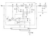
- FIG. 1is an exemplary schematic diagram of exemplary paralleled buck switching regulators, each with voltage and current control;
- FIGS. 2 and 3illustrate the simulated effect of using different exemplary component values for resistor 30 and capacitor 31 on the transition response of a switching regulator shown in FIG. 1 .
- an exemplary computing system 10has a switching regulator 11 for powering a load 12 including a microprocessor 13 .
- the switching regulator 11has a switch 20 , an inductor 21 and a filter capacitor 22 couples in series at respective junctions 23 , 24 , and an error amplifier 26 having an input for controlling the switch 20 .
- a first resistor 30is coupled between the junction 23 and a node 32 .
- a capacitor 31is coupled between node 32 and to the junction 24 . Node 32 is in turn coupled to the input of the error amplifier 26 .
- first resistor 30 and capacitor 31combine to be the feedback path for controlling the switching regulator 11 .
- the switching regulator 11here a buck regulator, takes an input voltage from input V IN and converts it to a lower voltage for use by load 12 .
- the load 12is illustrated here as a microprocessor 13 with an exemplary one of a plurality of bypass capacitors 14 (typically of different types and capacitance values) and inductance 15 (shown here as a lumped inductance) representing the distributed inductance of the power supply printed wiring board traces.
- the combined effect of capacitance 14 and inductance 15serves to smooth out the rapid transitions in current consumption by microprocessor 13 , described above.
- the switching regulator 11includes an illustrative switch 20 , a series inductor 21 (which includes an inherent resistance R W , discussed below), a filter capacitor 22 , and a flyback diode 25 . Coupled across inductor 21 is a resistor 30 in series with a capacitor 31 , joining together at node 32 . Node 32 in turn connects to an error amplifier 26 , having in combination impedances Z 1 , Z 2 and operational amplifier 27 . Impedances Z 1 and Z 2 may include reactive elements to achieve lead/lag compensation to the overall operation of the regulator 11 .
- the output of amplifier 26drives a conventional pulse-width modulator 28 .
- the modulator 28controls the opening and closing of switch 20 , which is preferably a MOSFET but may be a bipolar transistor or the like.
- the error amplifier 26controls the duty cycle of the switch 20 , while the switching frequency of the switch 20 remains substantially constant. It is understood, however, that other alternative techniques for controlling switch 20 may be used.
- resistor 30 and capacitor 31serve to provide to the error amplifier 26 signals representing the output voltage V 0 and output current I 0 from the regulator 11 .
- the output currentis substantially determined by the voltage drop across the resistance R W of inductor 21 . This resistance is usually very small, typically much smaller than the intentionally introduced resistor of prior art regulators, discussed above.
- the output voltageis measured indirectly, here by voltage on node 23 .
- the voltage on node 23is approximately V 0 +I 0 R W .
- the output voltage V 0is maintained to be substantially equal to V REF -I 0 R W .
- the output impedanceis approximately the resistance R W . Accordingly, the output voltage droops with increasing current I 0 . Since resistance R W is small, the amount of droop is correspondingly small and can be compensated for as discussed below.
- FIGS. 2 and 3illustrate the effect of different values for resistor 30 and capacitor 31 on the output voltage V 0 in response to changes in output current.
- the output voltage V 0decreases with increasing output current I 0 due to any voltage drop across resistance R W . While the resistance of R W is small, at high output currents several tens of millivolts may be dropped across it. To compensate for any voltage drop across the resistance R W a resistor 34 is added across capacitor 31 . In this case, the output voltage V 0 is approximately V REF - R 34 [ R 30 + R 34 ] - I O ⁇ R W
- R 30 and R 34is the resistance of resistors 30 and 34 , respectively.
- resistor 36is added to the error amplifier 26 .
- resistor 36combined with impedance Z 1 allows the output voltage V 0 to be scaled to the reference voltage V REF and can be set accordingly.
- FIG. 1shows multiple regulators 11 operating parallel and sharing a common reference voltage V REF to provide more current to the load 12 than one regulator 11 can provide individually. Because of the output current control by the regulators 11 , over current by any one of the regulators is avoided. Moreover, voltage and output current control by the regulators 11 compensate for differences in performance by the various pulse-width modulators 28 in the parallel regulators 11 .
Landscapes
- Engineering & Computer Science (AREA)
- Power Engineering (AREA)
- Physics & Mathematics (AREA)
- Electromagnetism (AREA)
- General Physics & Mathematics (AREA)
- Radar, Positioning & Navigation (AREA)
- Automation & Control Theory (AREA)
- Dc-Dc Converters (AREA)
Abstract
Description

Claims (50)
Priority Applications (1)
| Application Number | Priority Date | Filing Date | Title |
|---|---|---|---|
| US09/607,501USRE37738E1 (en) | 1996-10-09 | 2000-06-28 | Simple and efficient switching regulator for fast transient loads such as microprocessors |
Applications Claiming Priority (3)
| Application Number | Priority Date | Filing Date | Title |
|---|---|---|---|
| US2804196P | 1996-10-09 | 1996-10-09 | |
| US08/946,963US5877611A (en) | 1996-10-09 | 1997-10-08 | Simple and efficient switching regulator for fast transient loads such as microprocessors |
| US09/607,501USRE37738E1 (en) | 1996-10-09 | 2000-06-28 | Simple and efficient switching regulator for fast transient loads such as microprocessors |
Related Parent Applications (1)
| Application Number | Title | Priority Date | Filing Date |
|---|---|---|---|
| US08/946,963ReissueUS5877611A (en) | 1996-10-09 | 1997-10-08 | Simple and efficient switching regulator for fast transient loads such as microprocessors |
Publications (1)
| Publication Number | Publication Date |
|---|---|
| USRE37738E1true USRE37738E1 (en) | 2002-06-11 |
Family
ID=26703198
Family Applications (2)
| Application Number | Title | Priority Date | Filing Date |
|---|---|---|---|
| US08/946,963CeasedUS5877611A (en) | 1996-10-09 | 1997-10-08 | Simple and efficient switching regulator for fast transient loads such as microprocessors |
| US09/607,501Expired - LifetimeUSRE37738E1 (en) | 1996-10-09 | 2000-06-28 | Simple and efficient switching regulator for fast transient loads such as microprocessors |
Family Applications Before (1)
| Application Number | Title | Priority Date | Filing Date |
|---|---|---|---|
| US08/946,963CeasedUS5877611A (en) | 1996-10-09 | 1997-10-08 | Simple and efficient switching regulator for fast transient loads such as microprocessors |
Country Status (1)
| Country | Link |
|---|---|
| US (2) | US5877611A (en) |
Cited By (14)
| Publication number | Priority date | Publication date | Assignee | Title |
|---|---|---|---|---|
| US6531853B2 (en)* | 2000-11-21 | 2003-03-11 | Rohm Co., Ltd. | DC-DC converter |
| US6614136B2 (en)* | 2000-11-21 | 2003-09-02 | Intel Corporation | Voltage regulation system having an inductive current sensing element |
| US6642696B2 (en)* | 2001-08-03 | 2003-11-04 | Texas Instruments Incorporated | DC-DC converter with a feedback controller |
| US6801027B2 (en) | 2002-09-26 | 2004-10-05 | Itt Manufacturing Enterprises, Inc. | Power conversion in variable load applications |
| US20040232895A1 (en)* | 2003-05-20 | 2004-11-25 | Chi-Kun Chiu | Low noise fast stable voltage regulator circuit |
| US20050040800A1 (en)* | 2003-08-21 | 2005-02-24 | Sehat Sutardja | Digital low dropout regulator |
| US20050040796A1 (en)* | 2003-08-21 | 2005-02-24 | Marvell World Trade Ltd. | Voltage regulator |
| US7142400B1 (en)* | 2002-03-27 | 2006-11-28 | Cypress Semiconductor Corp. | Method and apparatus for recovery from power supply transient stress conditions |
| US20070176585A1 (en)* | 2004-07-13 | 2007-08-02 | Marvell World Trade Ltd. | Closed-loop digital control system for a DC/DC converter |
| US7332832B2 (en) | 2004-02-27 | 2008-02-19 | Hitachi Global Storage Technologies Netherlands B.V. | Removable hard disk drive (HDD) that is hot-plug compatible with multiple external power supply voltages |
| US20090085546A1 (en)* | 2007-09-28 | 2009-04-02 | Astec International Limited | Fast Transient Step Load Response in a Power Converter |
| US8324872B2 (en)* | 2004-03-26 | 2012-12-04 | Marvell World Trade, Ltd. | Voltage regulator with coupled inductors having high coefficient of coupling |
| US20130234690A1 (en)* | 2010-11-19 | 2013-09-12 | Megachips Corporation | Power supply device |
| US11387646B2 (en) | 2020-07-02 | 2022-07-12 | Hewlett Packard Enterprise Development Lp | Power management system for maintaining bus voltage |
Families Citing this family (61)
| Publication number | Priority date | Publication date | Assignee | Title |
|---|---|---|---|---|
| JPH11122913A (en)* | 1997-10-15 | 1999-04-30 | Mitsubishi Electric Corp | High voltage generation circuit |
| US6140808A (en)* | 1998-08-05 | 2000-10-31 | Intel Corporation | DC-to-DC converter with transient suppression |
| US6127814A (en)* | 1998-11-23 | 2000-10-03 | Switch Power, Inc. | System to protect switch mode DC/DC converters against overload current |
| DE60030424D1 (en)* | 1999-03-23 | 2006-10-12 | Advanced Energy Ind Inc | DC-POWERED COMPUTER SYSTEM WITH A HIGH-FREQUENCY SWITCHING POWER SUPPLY |
| US6545450B1 (en) | 1999-07-02 | 2003-04-08 | Advanced Energy Industries, Inc. | Multiple power converter system using combining transformers |
| US6249447B1 (en) | 1999-08-13 | 2001-06-19 | Tyco Electronics Logistics Ag | System and method for determining output current and converter employing the same |
| US6191566B1 (en)* | 1999-08-26 | 2001-02-20 | Lucent Technologies Inc. | Board mountable power supply module with multi-function control pin |
| US6246220B1 (en) | 1999-09-01 | 2001-06-12 | Intersil Corporation | Synchronous-rectified DC to DC converter with improved current sensing |
| US6181120B1 (en) | 1999-09-01 | 2001-01-30 | Intersil Corporation | Current mode dc/dc converter with controlled output impedance |
| USRE38780E1 (en) | 1999-09-01 | 2005-08-23 | Intersil Americas Inc. | Current mode DC/DC converter with controlled output impedance |
| US6680604B2 (en)* | 2000-03-27 | 2004-01-20 | Intersil Corporation | Methods to control the droop when powering dual mode processors and associated circuits |
| JP2001298945A (en)* | 2000-04-17 | 2001-10-26 | Taiyo Yuden Co Ltd | Driving method for power circuit, power circuit, and electronic part for power supply |
| TW521177B (en)* | 2000-08-31 | 2003-02-21 | Primarion Inc | Apparatus and system for providing transient suppression power regulation |
| US6975494B2 (en) | 2001-01-29 | 2005-12-13 | Primarion, Inc. | Method and apparatus for providing wideband power regulation to a microelectronic device |
| WO2002078159A2 (en)* | 2001-03-22 | 2002-10-03 | Primarion, Inc. | Power regulation system, apparatus, and method for providing regulated power to a microelectronic device |
| EP1413038B1 (en)* | 2001-07-05 | 2008-10-08 | Power-One, Inc. | Inductor current sensing in isolated switching regulators and related methods |
| US20040233690A1 (en)* | 2001-08-17 | 2004-11-25 | Ledenev Anatoli V. | Multiple power converter system using combining transformers |
| US6806689B2 (en)* | 2002-03-22 | 2004-10-19 | International Rectifier Corporation | Multi-phase buck converter |
| JP4364554B2 (en)* | 2002-06-07 | 2009-11-18 | 株式会社ルネサステクノロジ | Switching power supply device and switching power supply system |
| JP4251021B2 (en)* | 2002-06-17 | 2009-04-08 | 株式会社日立製作所 | Power supply device and hard disk device and IC using the same |
| EP1376295B1 (en)* | 2002-06-17 | 2008-08-13 | Hitachi, Ltd. | Power-supply device |
| US6677738B1 (en)* | 2002-08-23 | 2004-01-13 | Texas Instruments Incorporated | Overcurrent sensing using high side switch device in switching power converters |
| US7098637B2 (en)* | 2003-05-12 | 2006-08-29 | International Rectifier Corporation | Active voltage positioning implementation for microprocessor power supplies or the like |
| US8212317B2 (en)* | 2004-01-29 | 2012-07-03 | Enpirion, Inc. | Integrated circuit with a laterally diffused metal oxide semiconductor device and method of forming the same |
| US8253197B2 (en)* | 2004-01-29 | 2012-08-28 | Enpirion, Inc. | Integrated circuit with a laterally diffused metal oxide semiconductor device and method of forming the same |
| US8212316B2 (en)* | 2004-01-29 | 2012-07-03 | Enpirion, Inc. | Integrated circuit with a laterally diffused metal oxide semiconductor device and method of forming the same |
| US8253195B2 (en)* | 2004-01-29 | 2012-08-28 | Enpirion, Inc. | Integrated circuit with a laterally diffused metal oxide semiconductor device and method of forming the same |
| US7330017B2 (en)* | 2004-01-29 | 2008-02-12 | Enpirion, Inc. | Driver for a power converter and a method of driving a switch thereof |
| US7230302B2 (en) | 2004-01-29 | 2007-06-12 | Enpirion, Inc. | Laterally diffused metal oxide semiconductor device and method of forming the same |
| US8253196B2 (en)* | 2004-01-29 | 2012-08-28 | Enpirion, Inc. | Integrated circuit with a laterally diffused metal oxide semiconductor device and method of forming the same |
| US8212315B2 (en)* | 2004-01-29 | 2012-07-03 | Enpirion, Inc. | Integrated circuit with a laterally diffused metal oxide semiconductor device and method of forming the same |
| US7214985B2 (en)* | 2004-08-23 | 2007-05-08 | Enpirion, Inc. | Integrated circuit incorporating higher voltage devices and low voltage devices therein |
| US7234055B2 (en)* | 2004-08-24 | 2007-06-19 | Inventec Corporation | Computer operating booting system making use of multi-buttons |
| ITMI20041981A1 (en)* | 2004-10-19 | 2005-01-19 | St Microelectronics Srl | "DC / DC CONVERTER" |
| JP2006230186A (en)* | 2005-01-21 | 2006-08-31 | Renesas Technology Corp | Semiconductor device |
| US7919952B1 (en)* | 2005-03-21 | 2011-04-05 | Microsemi Corporation | Automatic gain control technique for current monitoring in current-mode switching regulators |
| US7521907B2 (en) | 2006-03-06 | 2009-04-21 | Enpirion, Inc. | Controller for a power converter and method of operating the same |
| US7893676B2 (en)* | 2006-07-20 | 2011-02-22 | Enpirion, Inc. | Driver for switch and a method of driving the same |
| US7948280B2 (en)* | 2006-10-20 | 2011-05-24 | Enpirion, Inc. | Controller including a sawtooth generator and method of operating the same |
| US8044650B2 (en)* | 2007-12-11 | 2011-10-25 | Infineon Technologies Austria Ag | Methods and apparatus for current sensing in mutually coupled inductors |
| US7876080B2 (en)* | 2007-12-27 | 2011-01-25 | Enpirion, Inc. | Power converter with monotonic turn-on for pre-charged output capacitor |
| US8410769B2 (en)* | 2008-04-16 | 2013-04-02 | Enpirion, Inc. | Power converter with controller operable in selected modes of operation |
| US8541991B2 (en)* | 2008-04-16 | 2013-09-24 | Enpirion, Inc. | Power converter with controller operable in selected modes of operation |
| US9246390B2 (en) | 2008-04-16 | 2016-01-26 | Enpirion, Inc. | Power converter with controller operable in selected modes of operation |
| US8686698B2 (en) | 2008-04-16 | 2014-04-01 | Enpirion, Inc. | Power converter with controller operable in selected modes of operation |
| US8692532B2 (en)* | 2008-04-16 | 2014-04-08 | Enpirion, Inc. | Power converter with controller operable in selected modes of operation |
| US7679342B2 (en)* | 2008-04-16 | 2010-03-16 | Enpirion, Inc. | Power converter with power switch operable in controlled current mode |
| US9548714B2 (en)* | 2008-12-29 | 2017-01-17 | Altera Corporation | Power converter with a dynamically configurable controller and output filter |
| US8698463B2 (en)* | 2008-12-29 | 2014-04-15 | Enpirion, Inc. | Power converter with a dynamically configurable controller based on a power conversion mode |
| US8299764B2 (en)* | 2009-04-24 | 2012-10-30 | Intersil Americas Inc. | System and method for determining output voltage level information from phase voltage for switched mode regulator controllers |
| US8450988B2 (en)* | 2010-10-05 | 2013-05-28 | Maxim Integrated Products, Inc. | Systems and methods for controlling inductive energy in DC-DC converters |
| US8867295B2 (en) | 2010-12-17 | 2014-10-21 | Enpirion, Inc. | Power converter for a memory module |
| US20140159130A1 (en) | 2012-11-30 | 2014-06-12 | Enpirion, Inc. | Apparatus including a semiconductor device coupled to a decoupling device |
| JP2015012694A (en)* | 2013-06-28 | 2015-01-19 | 株式会社東芝 | Power circuit |
| US9536938B1 (en) | 2013-11-27 | 2017-01-03 | Altera Corporation | Semiconductor device including a resistor metallic layer and method of forming the same |
| US10020739B2 (en) | 2014-03-27 | 2018-07-10 | Altera Corporation | Integrated current replicator and method of operating the same |
| US9673192B1 (en) | 2013-11-27 | 2017-06-06 | Altera Corporation | Semiconductor device including a resistor metallic layer and method of forming the same |
| US9391518B2 (en)* | 2014-06-11 | 2016-07-12 | Semiconductor Components Industries, Llc | Current sensing circuit for switching power converters |
| US10103627B2 (en) | 2015-02-26 | 2018-10-16 | Altera Corporation | Packaged integrated circuit including a switch-mode regulator and method of forming the same |
| US9509217B2 (en) | 2015-04-20 | 2016-11-29 | Altera Corporation | Asymmetric power flow controller for a power converter and method of operating the same |
| JP7424377B2 (en) | 2019-07-09 | 2024-01-30 | 株式会社村田製作所 | switching power supply |
Citations (9)
| Publication number | Priority date | Publication date | Assignee | Title |
|---|---|---|---|---|
| US4127885A (en)* | 1977-04-21 | 1978-11-28 | Rca Corporation | Over-current protection circuit for voltage regulator |
| US4761722A (en)* | 1987-04-09 | 1988-08-02 | Rca Corporation | Switching regulator with rapid transient response |
| US5055767A (en)* | 1990-06-29 | 1991-10-08 | Linear Technology Corporation | Analog multiplier in the feedback loop of a switching regulator |
| US5084666A (en)* | 1990-10-23 | 1992-01-28 | International Business Machines Corporation | Switchable output voltage converter |
| US5422562A (en)* | 1994-01-19 | 1995-06-06 | Unitrode Corporation | Switching regulator with improved Dynamic response |
| US5514947A (en)* | 1995-01-31 | 1996-05-07 | National Semiconductor Corporation | Phase lead compensation circuit for an integrated switching regulator |
| US5675240A (en)* | 1994-10-05 | 1997-10-07 | Mitsubishi Electric Semiconductor Software Corporation | All digital switching regulator for use in power supplies, battery chargers, and DC motor control circuits |
| US5747976A (en)* | 1996-03-26 | 1998-05-05 | Raytheon Company | Constant on-time architecture for switching regulators |
| US5770940A (en)* | 1995-08-09 | 1998-06-23 | Switch Power, Inc. | Switching regulator |
- 1997
- 1997-10-08USUS08/946,963patent/US5877611A/ennot_activeCeased
- 2000
- 2000-06-28USUS09/607,501patent/USRE37738E1/ennot_activeExpired - Lifetime
Patent Citations (9)
| Publication number | Priority date | Publication date | Assignee | Title |
|---|---|---|---|---|
| US4127885A (en)* | 1977-04-21 | 1978-11-28 | Rca Corporation | Over-current protection circuit for voltage regulator |
| US4761722A (en)* | 1987-04-09 | 1988-08-02 | Rca Corporation | Switching regulator with rapid transient response |
| US5055767A (en)* | 1990-06-29 | 1991-10-08 | Linear Technology Corporation | Analog multiplier in the feedback loop of a switching regulator |
| US5084666A (en)* | 1990-10-23 | 1992-01-28 | International Business Machines Corporation | Switchable output voltage converter |
| US5422562A (en)* | 1994-01-19 | 1995-06-06 | Unitrode Corporation | Switching regulator with improved Dynamic response |
| US5675240A (en)* | 1994-10-05 | 1997-10-07 | Mitsubishi Electric Semiconductor Software Corporation | All digital switching regulator for use in power supplies, battery chargers, and DC motor control circuits |
| US5514947A (en)* | 1995-01-31 | 1996-05-07 | National Semiconductor Corporation | Phase lead compensation circuit for an integrated switching regulator |
| US5770940A (en)* | 1995-08-09 | 1998-06-23 | Switch Power, Inc. | Switching regulator |
| US5747976A (en)* | 1996-03-26 | 1998-05-05 | Raytheon Company | Constant on-time architecture for switching regulators |
Cited By (23)
| Publication number | Priority date | Publication date | Assignee | Title |
|---|---|---|---|---|
| US6614136B2 (en)* | 2000-11-21 | 2003-09-02 | Intel Corporation | Voltage regulation system having an inductive current sensing element |
| US6531853B2 (en)* | 2000-11-21 | 2003-03-11 | Rohm Co., Ltd. | DC-DC converter |
| US6642696B2 (en)* | 2001-08-03 | 2003-11-04 | Texas Instruments Incorporated | DC-DC converter with a feedback controller |
| US7142400B1 (en)* | 2002-03-27 | 2006-11-28 | Cypress Semiconductor Corp. | Method and apparatus for recovery from power supply transient stress conditions |
| US6801027B2 (en) | 2002-09-26 | 2004-10-05 | Itt Manufacturing Enterprises, Inc. | Power conversion in variable load applications |
| US7019499B2 (en) | 2003-05-20 | 2006-03-28 | Mediatek Inc. | Low noise fast stable voltage regulator circuit |
| US20040232895A1 (en)* | 2003-05-20 | 2004-11-25 | Chi-Kun Chiu | Low noise fast stable voltage regulator circuit |
| US20100277141A1 (en)* | 2003-08-21 | 2010-11-04 | Sehat Sutardja | Digital low dropout regulator |
| US20050040800A1 (en)* | 2003-08-21 | 2005-02-24 | Sehat Sutardja | Digital low dropout regulator |
| US8299763B2 (en) | 2003-08-21 | 2012-10-30 | Marvell World Trade Ltd. | Digital low dropout regulator |
| US20050040796A1 (en)* | 2003-08-21 | 2005-02-24 | Marvell World Trade Ltd. | Voltage regulator |
| US7872454B2 (en) | 2003-08-21 | 2011-01-18 | Marvell World Trade Ltd. | Digital low dropout regulator |
| US7760525B2 (en) | 2003-08-21 | 2010-07-20 | Marvell World Trade Ltd. | Voltage regulator |
| US7332832B2 (en) | 2004-02-27 | 2008-02-19 | Hitachi Global Storage Technologies Netherlands B.V. | Removable hard disk drive (HDD) that is hot-plug compatible with multiple external power supply voltages |
| US8324872B2 (en)* | 2004-03-26 | 2012-12-04 | Marvell World Trade, Ltd. | Voltage regulator with coupled inductors having high coefficient of coupling |
| US8183846B2 (en) | 2004-07-13 | 2012-05-22 | Marvell World Trade Ltd. | Method and apparatus for controlling a DC/DC converter |
| US20100171478A1 (en)* | 2004-07-13 | 2010-07-08 | Runsheng He | Closed-loop digital control system for a dc/dc converter |
| US7679347B2 (en) | 2004-07-13 | 2010-03-16 | Marvell World Trade Ltd. | Closed-loop digital control system for a DC/DC converter |
| US20070176585A1 (en)* | 2004-07-13 | 2007-08-02 | Marvell World Trade Ltd. | Closed-loop digital control system for a DC/DC converter |
| US8232786B2 (en) | 2007-09-28 | 2012-07-31 | Astec International Limited | Fast transient step load response in a power converter |
| US20090085546A1 (en)* | 2007-09-28 | 2009-04-02 | Astec International Limited | Fast Transient Step Load Response in a Power Converter |
| US20130234690A1 (en)* | 2010-11-19 | 2013-09-12 | Megachips Corporation | Power supply device |
| US11387646B2 (en) | 2020-07-02 | 2022-07-12 | Hewlett Packard Enterprise Development Lp | Power management system for maintaining bus voltage |
Also Published As
| Publication number | Publication date |
|---|---|
| US5877611A (en) | 1999-03-02 |
Similar Documents
| Publication | Publication Date | Title |
|---|---|---|
| USRE37738E1 (en) | Simple and efficient switching regulator for fast transient loads such as microprocessors | |
| EP1415386B1 (en) | Simple and efficient switching regulator for fast transient loads | |
| KR100545867B1 (en) | Dynamic regulator for a dc-to-dc power converter and related methods | |
| US8274267B2 (en) | Hybrid power converter | |
| US7498783B2 (en) | Extending the continuous mode of operation for a buck converter | |
| US20090295344A1 (en) | Power-regulator circuit having two operating modes | |
| US6801026B2 (en) | Hysteretic DC-DC converters | |
| US6229350B1 (en) | Accurate, fast, and user programmable hysteretic comparator | |
| US20050194839A1 (en) | Versatile and intelligent power controller | |
| US6525516B2 (en) | Switching regulator with capacitance near load | |
| US6583520B2 (en) | Dual-switching and dual-linear power controller chip | |
| WO2010083753A1 (en) | Circuit and method for providing power supply voltage for wireless network card | |
| US10177650B2 (en) | Switching regulator synchronous node snubber circuit | |
| JP4251021B2 (en) | Power supply device and hard disk device and IC using the same | |
| US20060226822A1 (en) | Input current sensing AVP method for future VRM | |
| KR100881537B1 (en) | Droop Amplifier Circuits and Multiphase DC-DC Converters for DC-DC Regulators | |
| US20190305684A1 (en) | Apparatus for Power Converter with Improved Performance and Associated Methods | |
| US6005303A (en) | Linear voltage regulator compatible with bipolar and MOSFET pass devices and associated methods | |
| US5916313A (en) | Low cost power converter for a computer | |
| EP0928056A2 (en) | Voltage loss compensation for dc-dc converters | |
| He et al. | A High-Efficiency Fast-Transient Double Hysteretic Control Point-of-Load Converter | |
| CN119448715A (en) | Digital Controller | |
| CN119945118A (en) | Methods for managing efficiency losses in reactive power stages of multiphase switching converters | |
| CN116094285A (en) | Extensible load point power supply | |
| Wojtasik et al. | A novel approach for enhancement of DC/DC converter dynamic response |
Legal Events
| Date | Code | Title | Description |
|---|---|---|---|
| FPAY | Fee payment | Year of fee payment:4 | |
| SULP | Surcharge for late payment | ||
| FPAY | Fee payment | Year of fee payment:8 | |
| AS | Assignment | Owner name:TYCO ELECTRONICS LOGISTICS A.G., SWITZERLAND Free format text:ASSIGNMENT OF ASSIGNORS INTEREST;ASSIGNOR:LUCENT TECHNOLOGIES INC.;REEL/FRAME:020097/0847 Effective date:20001229 | |
| AS | Assignment | Owner name:LINEAGE OVERSEAS CORP., DELAWARE Free format text:ASSIGNMENT OF ASSIGNORS INTEREST;ASSIGNOR:TYCO ELECTRONICS LOGISTICS AG;REEL/FRAME:020609/0580 Effective date:20080228 Owner name:LINEAGE POWER CORPORATION, TEXAS Free format text:ASSIGNMENT OF ASSIGNORS INTEREST;ASSIGNOR:LINEAGE OVERSEAS CORP.;REEL/FRAME:020582/0184 Effective date:20080228 | |
| AS | Assignment | Owner name:WELLS FARGO FOOTHILL, LLC, AS AGENT,CALIFORNIA Free format text:SECURITY AGREEMENT;ASSIGNOR:LINEAGE POWER CORPORATION;REEL/FRAME:021876/0066 Effective date:20081121 Owner name:WELLS FARGO FOOTHILL, LLC, AS AGENT, CALIFORNIA Free format text:SECURITY AGREEMENT;ASSIGNOR:LINEAGE POWER CORPORATION;REEL/FRAME:021876/0066 Effective date:20081121 | |
| FPAY | Fee payment | Year of fee payment:12 | |
| AS | Assignment | Owner name:LINEAGE POWER CORPORATION, TEXAS Free format text:PATENT RELEASE AND REASSIGNMENT;ASSIGNOR:WELLS FARGO CAPITAL FINANCE, LLC;REEL/FRAME:027934/0566 Effective date:20110228 | |
| AS | Assignment | Owner name:GENERAL ELECTRIC CORPORATION, NEW YORK Free format text:ASSIGNMENT OF ASSIGNORS INTEREST;ASSIGNOR:GE POWER ELECTRONICS INC. FORMERLY LINEAGE POWER CORP.;REEL/FRAME:028090/0274 Effective date:20120411 | |
| AS | Assignment | Owner name:GENERAL ELECTRIC COMPANY, NEW YORK Free format text:PATENT ASSIGNMENT;ASSIGNOR:GE POWER ELECTRONICS INC.;REEL/FRAME:028316/0284 Effective date:20120525 | |
| AS | Assignment | Owner name:ABB SCHWEIZ AG, SWITZERLAND Free format text:ASSIGNMENT OF ASSIGNORS INTEREST;ASSIGNOR:GENERAL ELECTRIC COMPANY;REEL/FRAME:050207/0405 Effective date:20180720 Owner name:LUCENT TECHNOLOGIES INC., NEW JERSEY Free format text:ASSIGNMENT OF ASSIGNORS INTEREST;ASSIGNOR:BRKOVIC, MILIVOJE SLOBODAN;REEL/FRAME:050205/0969 Effective date:19971016 | |
| AS | Assignment | Owner name:ABB POWER ELECTRONICS INC., TEXAS Free format text:ASSIGNMENT OF ASSIGNORS INTEREST;ASSIGNOR:ABB SCHWEIZ AG;REEL/FRAME:052430/0136 Effective date:20200207 |