USRE37284E1 - Corrosion resistant PEM fuel cell - Google Patents
Corrosion resistant PEM fuel cellDownload PDFInfo
- Publication number
- USRE37284E1 USRE37284E1US09/504,349US50434900AUSRE37284EUS RE37284 E1USRE37284 E1US RE37284E1US 50434900 AUS50434900 AUS 50434900AUS RE37284 EUSRE37284 EUS RE37284E
- Authority
- US
- United States
- Prior art keywords
- fuel cell
- protective coating
- stainless steel
- core
- corrosion
- Prior art date
- Legal status (The legal status is an assumption and is not a legal conclusion. Google has not performed a legal analysis and makes no representation as to the accuracy of the status listed.)
- Expired - Lifetime
Links
- 239000000446fuelSubstances0.000titleclaimsabstractdescription51
- 238000005260corrosionMethods0.000titleclaimsabstractdescription34
- 230000007797corrosionEffects0.000titleclaimsabstractdescription31
- 229910001220stainless steelInorganic materials0.000claimsabstractdescription34
- 229910052782aluminiumInorganic materials0.000claimsabstractdescription22
- 229910052751metalInorganic materials0.000claimsabstractdescription16
- 239000002184metalSubstances0.000claimsabstractdescription16
- NRTOMJZYCJJWKI-UHFFFAOYSA-NTitanium nitrideChemical compound[Ti]#NNRTOMJZYCJJWKI-UHFFFAOYSA-N0.000claimsabstractdescription11
- 239000010936titaniumSubstances0.000claimsabstractdescription11
- 230000004888barrier functionEffects0.000claimsabstractdescription10
- 229910052759nickelInorganic materials0.000claimsabstractdescription9
- 229910052719titaniumInorganic materials0.000claimsabstractdescription8
- 229910052750molybdenumInorganic materials0.000claimsabstractdescription7
- 230000003647oxidationEffects0.000claimsabstractdescription6
- 238000007254oxidation reactionMethods0.000claimsabstractdescription6
- 238000000576coating methodMethods0.000claimsdescription31
- 239000010935stainless steelSubstances0.000claimsdescription30
- XAGFODPZIPBFFR-UHFFFAOYSA-NaluminiumChemical compound[Al]XAGFODPZIPBFFR-UHFFFAOYSA-N0.000claimsdescription20
- PXHVJJICTQNCMI-UHFFFAOYSA-NnickelSubstances[Ni]PXHVJJICTQNCMI-UHFFFAOYSA-N0.000claimsdescription16
- 239000011651chromiumSubstances0.000claimsdescription13
- 239000011248coating agentSubstances0.000claimsdescription12
- 230000007547defectEffects0.000claimsdescription9
- 229910052804chromiumInorganic materials0.000claimsdescription7
- 239000003792electrolyteSubstances0.000claimsdescription7
- RTAQQCXQSZGOHL-UHFFFAOYSA-NTitaniumChemical compound[Ti]RTAQQCXQSZGOHL-UHFFFAOYSA-N0.000claimsdescription6
- 239000012528membraneSubstances0.000claimsdescription6
- 229910045601alloyInorganic materials0.000claimsdescription5
- 239000000956alloySubstances0.000claimsdescription5
- VYZAMTAEIAYCRO-UHFFFAOYSA-NChromiumChemical compound[Cr]VYZAMTAEIAYCRO-UHFFFAOYSA-N0.000claimsdescription4
- ZOKXTWBITQBERF-UHFFFAOYSA-NMolybdenumChemical compound[Mo]ZOKXTWBITQBERF-UHFFFAOYSA-N0.000claimsdescription4
- 239000011733molybdenumSubstances0.000claimsdescription4
- 238000002161passivationMethods0.000claimsdescription3
- 239000011253protective coatingSubstances0.000claims11
- 150000002500ionsChemical class0.000claims2
- 230000001590oxidative effectEffects0.000claims2
- 239000010410layerSubstances0.000abstractdescription19
- 230000001681protective effectEffects0.000abstractdescription8
- 239000011241protective layerSubstances0.000abstractdescription6
- 239000011229interlayerSubstances0.000abstractdescription2
- ATJFFYVFTNAWJD-UHFFFAOYSA-NTinChemical compound[Sn]ATJFFYVFTNAWJD-UHFFFAOYSA-N0.000description29
- 238000012360testing methodMethods0.000description19
- 239000010408filmSubstances0.000description18
- 239000000758substrateSubstances0.000description15
- OKTJSMMVPCPJKN-UHFFFAOYSA-NCarbonChemical compound[C]OKTJSMMVPCPJKN-UHFFFAOYSA-N0.000description13
- 230000010287polarizationEffects0.000description11
- 229910052799carbonInorganic materials0.000description7
- 238000000151depositionMethods0.000description7
- 230000008021depositionEffects0.000description6
- 229910002804graphiteInorganic materials0.000description6
- 239000010439graphiteSubstances0.000description6
- 239000007789gasSubstances0.000description5
- 239000000203mixtureSubstances0.000description5
- 238000005240physical vapour depositionMethods0.000description5
- UFHFLCQGNIYNRP-UHFFFAOYSA-NHydrogenChemical compound[H][H]UFHFLCQGNIYNRP-UHFFFAOYSA-N0.000description4
- BQCADISMDOOEFD-UHFFFAOYSA-NSilverChemical compound[Ag]BQCADISMDOOEFD-UHFFFAOYSA-N0.000description4
- 238000004833X-ray photoelectron spectroscopyMethods0.000description4
- 238000000429assemblyMethods0.000description4
- 230000000694effectsEffects0.000description4
- 239000001257hydrogenSubstances0.000description4
- 229910052739hydrogenInorganic materials0.000description4
- 238000000034methodMethods0.000description4
- 239000002245particleSubstances0.000description4
- 239000000523sampleSubstances0.000description4
- 229910052709silverInorganic materials0.000description4
- 239000004332silverSubstances0.000description4
- 238000004544sputter depositionMethods0.000description4
- OKKJLVBELUTLKV-UHFFFAOYSA-NMethanolChemical compoundOCOKKJLVBELUTLKV-UHFFFAOYSA-N0.000description3
- 238000002441X-ray diffractionMethods0.000description3
- 238000004453electron probe microanalysisMethods0.000description3
- 239000004744fabricSubstances0.000description3
- 150000002739metalsChemical class0.000description3
- 239000003973paintSubstances0.000description3
- 229920000642polymerPolymers0.000description3
- 239000010409thin filmSubstances0.000description3
- XKRFYHLGVUSROY-UHFFFAOYSA-NArgonChemical compound[Ar]XKRFYHLGVUSROY-UHFFFAOYSA-N0.000description2
- UQSXHKLRYXJYBZ-UHFFFAOYSA-NIron oxideChemical compound[Fe]=OUQSXHKLRYXJYBZ-UHFFFAOYSA-N0.000description2
- 230000000712assemblyEffects0.000description2
- QVGXLLKOCUKJST-UHFFFAOYSA-Natomic oxygenChemical compound[O]QVGXLLKOCUKJST-UHFFFAOYSA-N0.000description2
- 230000003197catalytic effectEffects0.000description2
- 230000008859changeEffects0.000description2
- 238000005229chemical vapour depositionMethods0.000description2
- 239000008199coating compositionSubstances0.000description2
- 238000004090dissolutionMethods0.000description2
- 238000001755magnetron sputter depositionMethods0.000description2
- 230000003287optical effectEffects0.000description2
- 239000001301oxygenSubstances0.000description2
- 229910052760oxygenInorganic materials0.000description2
- 239000007787solidSubstances0.000description2
- 238000010301surface-oxidation reactionMethods0.000description2
- 238000011179visual inspectionMethods0.000description2
- XXSPKSHUSWQAIZ-UHFFFAOYSA-L36026-88-7Chemical compound[Ni+2].[O-]P=O.[O-]P=OXXSPKSHUSWQAIZ-UHFFFAOYSA-L0.000description1
- 229910000871AL-6XNInorganic materials0.000description1
- 229910000967As alloyInorganic materials0.000description1
- BVKZGUZCCUSVTD-UHFFFAOYSA-MBicarbonateChemical compoundOC([O-])=OBVKZGUZCCUSVTD-UHFFFAOYSA-M0.000description1
- LSNNMFCWUKXFEE-UHFFFAOYSA-MBisulfiteChemical compoundOS([O-])=OLSNNMFCWUKXFEE-UHFFFAOYSA-M0.000description1
- 229920000557Nafion®Polymers0.000description1
- 229910001096P alloyInorganic materials0.000description1
- QAOWNCQODCNURD-UHFFFAOYSA-NSulfuric acidChemical compoundOS(O)(=O)=OQAOWNCQODCNURD-UHFFFAOYSA-N0.000description1
- 239000003929acidic solutionSubstances0.000description1
- 230000009471actionEffects0.000description1
- 230000004913activationEffects0.000description1
- 229910052786argonInorganic materials0.000description1
- 230000009286beneficial effectEffects0.000description1
- 239000012159carrier gasSubstances0.000description1
- 238000012512characterization methodMethods0.000description1
- 238000005234chemical depositionMethods0.000description1
- 238000006243chemical reactionMethods0.000description1
- 239000004020conductorSubstances0.000description1
- 230000003247decreasing effectEffects0.000description1
- 230000001419dependent effectEffects0.000description1
- ZOMNIUBKTOKEHS-UHFFFAOYSA-Ldimercury dichlorideChemical classCl[Hg][Hg]ClZOMNIUBKTOKEHS-UHFFFAOYSA-L0.000description1
- 238000010292electrical insulationMethods0.000description1
- 230000004907fluxEffects0.000description1
- 239000003456ion exchange resinSubstances0.000description1
- 229920003303ion-exchange polymerPolymers0.000description1
- 229910052742ironInorganic materials0.000description1
- XEEYBQQBJWHFJM-UHFFFAOYSA-NironSubstances[Fe]XEEYBQQBJWHFJM-UHFFFAOYSA-N0.000description1
- 239000000463materialSubstances0.000description1
- 238000005259measurementMethods0.000description1
- OFNHPGDEEMZPFG-UHFFFAOYSA-NphosphanylidynenickelChemical group[P].[Ni]OFNHPGDEEMZPFG-UHFFFAOYSA-N0.000description1
- 239000011148porous materialSubstances0.000description1
- 230000008569processEffects0.000description1
- 230000005855radiationEffects0.000description1
- 239000000376reactantSubstances0.000description1
- 238000005546reactive sputteringMethods0.000description1
- 239000006104solid solutionSubstances0.000description1
- 239000000243solutionSubstances0.000description1
Images


Classifications
- H—ELECTRICITY
- H01—ELECTRIC ELEMENTS
- H01M—PROCESSES OR MEANS, e.g. BATTERIES, FOR THE DIRECT CONVERSION OF CHEMICAL ENERGY INTO ELECTRICAL ENERGY
- H01M8/00—Fuel cells; Manufacture thereof
- H01M8/02—Details
- H01M8/0202—Collectors; Separators, e.g. bipolar separators; Interconnectors
- H01M8/0204—Non-porous and characterised by the material
- H01M8/0223—Composites
- H01M8/0228—Composites in the form of layered or coated products
- H—ELECTRICITY
- H01—ELECTRIC ELEMENTS
- H01M—PROCESSES OR MEANS, e.g. BATTERIES, FOR THE DIRECT CONVERSION OF CHEMICAL ENERGY INTO ELECTRICAL ENERGY
- H01M8/00—Fuel cells; Manufacture thereof
- H01M8/02—Details
- H01M8/0202—Collectors; Separators, e.g. bipolar separators; Interconnectors
- H01M8/0204—Non-porous and characterised by the material
- H01M8/0206—Metals or alloys
- H—ELECTRICITY
- H01—ELECTRIC ELEMENTS
- H01M—PROCESSES OR MEANS, e.g. BATTERIES, FOR THE DIRECT CONVERSION OF CHEMICAL ENERGY INTO ELECTRICAL ENERGY
- H01M2300/00—Electrolytes
- H01M2300/0017—Non-aqueous electrolytes
- H01M2300/0065—Solid electrolytes
- H01M2300/0082—Organic polymers
- H—ELECTRICITY
- H01—ELECTRIC ELEMENTS
- H01M—PROCESSES OR MEANS, e.g. BATTERIES, FOR THE DIRECT CONVERSION OF CHEMICAL ENERGY INTO ELECTRICAL ENERGY
- H01M8/00—Fuel cells; Manufacture thereof
- H01M8/02—Details
- H01M8/0202—Collectors; Separators, e.g. bipolar separators; Interconnectors
- H01M8/0204—Non-porous and characterised by the material
- H01M8/0206—Metals or alloys
- H01M8/0208—Alloys
- H—ELECTRICITY
- H01—ELECTRIC ELEMENTS
- H01M—PROCESSES OR MEANS, e.g. BATTERIES, FOR THE DIRECT CONVERSION OF CHEMICAL ENERGY INTO ELECTRICAL ENERGY
- H01M8/00—Fuel cells; Manufacture thereof
- H01M8/02—Details
- H01M8/0202—Collectors; Separators, e.g. bipolar separators; Interconnectors
- H01M8/0204—Non-porous and characterised by the material
- H01M8/0215—Glass; Ceramic materials
- Y—GENERAL TAGGING OF NEW TECHNOLOGICAL DEVELOPMENTS; GENERAL TAGGING OF CROSS-SECTIONAL TECHNOLOGIES SPANNING OVER SEVERAL SECTIONS OF THE IPC; TECHNICAL SUBJECTS COVERED BY FORMER USPC CROSS-REFERENCE ART COLLECTIONS [XRACs] AND DIGESTS
- Y02—TECHNOLOGIES OR APPLICATIONS FOR MITIGATION OR ADAPTATION AGAINST CLIMATE CHANGE
- Y02E—REDUCTION OF GREENHOUSE GAS [GHG] EMISSIONS, RELATED TO ENERGY GENERATION, TRANSMISSION OR DISTRIBUTION
- Y02E60/00—Enabling technologies; Technologies with a potential or indirect contribution to GHG emissions mitigation
- Y02E60/30—Hydrogen technology
- Y02E60/50—Fuel cells
Definitions
- This inventionrelates to PEM fuel cells and more particularly to corrosion-resistant electrical contact elements therefor.
- Fuel cellshave been proposed as a power source for electric vehicles.
- One such fuel cellis the PEM (i.e., Proton Exchange Membrane) fuel cell as it has potentially high energy and low weight, both of which are highly desirable for mobile electric vehicles.
- PEM fuel cellsare well known in the art, and include a so-called “membrane-electrode-assembly” comprising a thin, solid polymer membrane-electrolyte having an anode on one face of the membrane-electrolyte and a cathode on the opposite face of the membrane-electrolyte.
- the membrane-electrode-assemblyis sandwiched between a pair of electrically conductive elements which serve as current collectors for the anode/cathode and often contain appropriate channels and openings therein for distributing the fuel cell's gaseous reactants (e.g., H 2 & O 2 /air)over the surfaces of the respective anode and cathode.
- the anode and cathodethemselves typically comprise finely divided carbon particles, very finely divided catalytic particles supported on the internal and external surfaces of the carbon particles, and proton conductive material intermingled with the catalytic and carbon particles.
- One such membrane-electrode-assembly and fuel cellis described in U.S. Pat. No. 5,272,017 issued Dec. 21, 1993 and assigned to the assignee of the present invention.
- bipolar PEM fuel cellswherein a plurality of the membrane-electrode-assemblies are stacked together in electrical series while being separated one from the next by an impermeable, electrically conductive contact element often referred to as a bipolar plate or septum.
- the bipolar septum/plateelectrically conducts current between the anode of one cell to the cathode of the next adjacent cell in the stack.
- the bipolar platesare in constant contact with highly acidic solutions (pH 3.5) containing F ⁇ , SO 4 — , SO 3 ⁇ , HSO 4 ⁇ , CO 3 — , and HCO 3 ⁇ , etc.
- highly acidic solutionspH 3.5
- the cathodems polarized to a maximum of about +1 V vs. the normal hydrogen electrode and exposed to pressurized air, and the anode is exposed to pressurized hydrogen or methanol reformat.
- metal contact elementsincluding bipolar plates/septums
- contact elementsare often fabricated from graphite which is light-weight, corrosion-resistant, and electrically conductive in the PEM fuel cell environment.
- graphiteis quite fragile which makes it difficult to mechanically handle and process contact elements made therefrom.
- graphiteis, quite porous making it virtually impossible to make very thin gas impervious plates. The pores in graphite often lead to gas permeation under the fuel cell's operating pressure which could lead to the undesirable mixing of H 2 and O 2 .
- the electrical and thermal conductivity of graphiteis quite low compared with light weight metals such as aluminum and titanium and their alloys. Unfortunately, such light weight metals are either not corrosion resistant in the PEM fuel cell environment, and contact elements made therefrom deteriorate rapidly, or they form highly electronically resistive oxide films on their surface that increases the internal resistance of the fuel cell and reduces its performance.
- the present inventioncontemplates a PEM fuel cell having electrical contact elements (including bipolar plates/septums) comprising a titanium nitride coated light weight metal (e.g., Al or Ti) core, having a protective metal layer intermediate the core and the titanium nitride.
- the protective layeris susceptible to oxidation in the operating environment of the fuel cell so as to form an barrier to further corrosion at sites where the layer is exposed to such environment. Oxides formed on the protective metal layer have relatively low electrical resistivity so as not to substantially increase the internal resistance of the fuel cell.
- a particularly effective such protective layercomprises stainless steels rich in chromium, nickel and molybdenum (hereinafter Cr/Ni/Mo-rich).
- Cr/Ni/Mo-rich stainless steelmeans a stainless steel containing at least about 16% by weight Cr., at least about 20% by weight Ni, and at least 3% by weight Mo.
- Another material potentially useful as a protective interlayer between the core and the titanium nitride topcoatis a nickel-phosphorus alloy formed by electroless chemical deposition from nickel hypophosphite solutions uing using techniques well known to those skilled in the art.
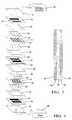
- FIG. 1is a schematic, isometric, exploded view of a bipolar PEM fuel cell
- FIG. 2is sectioned view through the bipolar plate of FIG. 1;
- FIG. 3is a potentiodynamic polarization curve of a bare aluminum 6061-T6 in a simulated fuel cell environment
- FIG. 4are typical potentiodynamic polarization curves for aluminum coated with (a) just stainless steel, and (2) both stainless steel and TiN in a simulated fuel cell environment;
- FIG. 5is a current vs. time plot of a TiN/SS-coated aluminum substrate at a constant anodic polarization of 760 mV vs. SCE;
- FIG. 6is a measured resistance plot for different lengths of “as-deposited”and “ post corrosion testing ” of a TiN film.
- FIG. 1depicts a two cell, bipolar PEM fuel cell having a pair of membrane-electrode-assemblies 4 and 6 separated from each other by electrically conductive bipolar septum/plate 8 .
- the membrane-electrode assemblies 4 and 6 , and bipolar septum/plate 8are stacked together between stainless steel clamps 10 and 12 and end contact elements 14 and 16 .
- the end contact elements 14 and 16 as well as the bipolar septum/plate 8contain a plurality of channels and openings 18 , 20 , 22 , and 24 for distributing reaction gases (i.e., H 2 & O 2 ) to the membrane-electrode assemblies 4 and 6 .
- Non-conductive gaskets 26 , 28 , 30 , and 32provide seals and electrical insulation between the several components of the fuel cell.
- Gas permeable carbon cloth current collectors 34 and 36press up against the anode sides of the membrane electrode assembly (not shown) and the cathode sides 42 and 44 .
- the anode and cathode sides of the membrane-electrode assemblyare separated from each other by a solid polymer membrane-electrolyte (SPE) 43 and 45 .
- SPEsolid polymer membrane-electrolyte
- such membranesare made from ion exchange resins, and typically comprise a perflourinated sulfonic acid polymer such as NAFION available from the E.I. DuPont de Nemours & Co.
- the end contact elements 14 and 16press up against the carbon sheets 34 and 40 respectively, while the bipolar septum/plate 8 presses up against the carbon cloth 36 on one face (i.e., the cathode face) thereof, and against carbon cloth 38 on the opposite face (i.e., the anode face).
- Oxygenis supplied to the cathode side of the fuel cell from storage tank 46
- hydrogenis supplied to the anode side of the fuel cell from storage tank or reformer 48 .
- At least one of the bipolar septum/plate 8 or the end contact elements 14 and 16will comprise a core 50 of a light weight metal such as aluminum or titanium.
- aluminum and titaniumare intended to include not only the pure metals but their respective alloys.
- a barrier/protective layer 52 of a metal which forms a low resistance, passivating oxide filmis deposited onto the core 50 , and is covered with a topcoat of titanium nitride 54 .
- barrier/protective layers 52have been found to be excellent such barrier/protective layers 52 as they form a dense oxide layer which inhibits further corrosion, but which does not significantly increase the fuel cell's internal resistance.
- a particularly effective such stainless steel for this purposeis commercially available from the Rolled Alloy Company as alloy AL-6XN, and contains 23 ⁇ 2% by weight chromium, 21 ⁇ 2% by weight nickel, and 6 ⁇ 2% by weight molybdenum.
- electrolessly deposited nickel-phosphorous alloysappear to have good potential as a substitute for the stainless steel in that they readily form a passivating film when exposed to the fuel cell environment which provides a barrier to further oxidation/corrosion of the underlying coating.
- TiNis difficult to deposit in a perfectly continuous layer, and microdiscontinuities/submicron-defects in the TiN coating expose the underlying metal to the corrosive environment of the fuel cell. Were the immediately underlying metal to be aluminum or titanium, it would rapidly corrode. or form an insulating oxide film at, the sites of the discontinuities.
- Cr/Ni/Mo/-rich stainless steelsare much more corrosion resistant than aluminum owing to their ability to passivate against further corrosion by growing a protective oxide barrier at the sites of the discontinuities, and accordingly provide an excellent protective barrier for the aluminum.
- the barrier/protective stainless steel layer, and the TIN topcoatare preferably deposited onto the light weight metal core using conventional physical vapor deposition (PVD) techniques (e.g.. magnetron sputtering), or chemical vapor deposition (CVD) techniques known to those skilled in these arts.
- PVDphysical vapor deposition
- CVDchemical vapor deposition
- Strong, pinhole-free, stainless steel layers 10 ⁇ m thickcan be PVD deposited without difficulty, and have proved to be effective protective layers.
- Stainless steel layers deposited at greater PVD substrate biasesi.e. greater than about 270 V
- TiN layers deposited at greater PVD substrate biasesi.e. greater than about 60 V have been found to be better than those deposited at lowere biases.
- the TiN topcoatwas produced by reactive sputtering of Ti in an Ar/N 2 mixture.
- the TiN deposition ratewas about 2 angstroms per second (A ⁇ /sec) with a bias of 120 V for a total TiN thickness of about 3000 angstroms.
- Stainless steel and TiN thin filmswere also deposited onto Si substrates at different bias levels for the purpose of characterizing the films. Additional samples were made with TiN films deposited directly atop the aluminum (i.e.. sans stainless steel) with an industrial scale sputter coating machine at about 350° C.
- All of the stainless steel and TiN coatingswere examined by ⁇ -2 ⁇ X-Ray diffraction using a Siemens D 500 ⁇ -74 diffractometer with CuK 60 radiation to determine their structures.
- the coating compositionswere quantitatively measured by electron probe microanalysis. Samples were examined by x-ray photoelectron spectroscopy (XPS) depth profile after the corrosion test to determine if the coating composition was uniform.
- XPSx-ray photoelectron spectroscopy
- the stainless steel coatings deposited at different biasesconsist mainly of Fe, Cr, Ni, and Mo, shown in Table I, as measured by EPMA.
- the X-ray diffraction (XRD) spectra of these stainless steel filmsindicate that the coatings comprise a mixture of bcc ( ⁇ ) and fcc ( ⁇ ) solid solutions.
- the d-spacing corresponding to ⁇ (111), ⁇ (110) and ⁇ (200) peakswere obtained by fitting them with Lorentzians and are given in Table II.
- the substrate biasbe higher than 60 V when depositing corrosion resistant TiN films for fuel cell applications.
- the TiN filmswere also examined under an optical microscope. Submicrometer defects were observed in all samples made by both the laboratory coating system and industrial scale sputtering machine.
- CORROSION TESTSCorrosion tests were conducted in an electrolyte containing 10 ⁇ 4 M H 2 SO 4 and about 2 ppm HF at 90° C. (open to air) to simulate the PEM fuel cell environment. Samples (1.2 cm 2 area) were examined by potentiodynamic polarization (PDP), and constant anodic polarization of an IBM/AT EG&G-controlled PAR model 273 potentiostat. A saturated calomel electrode (SCE) and a graphite rod were used as reference and counter electrodes respectively. The voltage scan rate was 1 mV/sec in the PDP test. In addition, two TiN coated aluminum end plates were tested in an actual fuel cell test.
- PDPpotentiodynamic polarization
- SCEsaturated calomel electrode
- graphite rodwere used as reference and counter electrodes respectively. The voltage scan rate was 1 mV/sec in the PDP test.
- two TiN coated aluminum end plateswere tested in an actual fuel cell test.
- a bare Al samplewas first tested in the simulated fuel cell environment.
- a current density-voltage curve of a bare aluminum 6061-T6 sample tested in the corrosion test cellis shown in FIG. 3 .
- Severe pitting on the surfacewas observed by visual inspection about one minute after the sample was polarized at +760 mV vs. SCE.
- a similar phenomenonwas also observed on TiN (ca. 2 ⁇ m thick) coated aluminum where pits initiated from defect areas of the TiN films about one (1) minute after the anodic voltage was applied.
- two TiN coated aluminum end contact elementswere tested during actual fuel cell operation in order to compare the corrosion behavior of the coatings in the simulated environment with that in the actual fuel cell environment.
- the performance of the H 2 —O 2 fuel cell at 90° C., 30 psig back pressureimproved for the first five hours due to activation of the membrane-electrode-assembly, and then maintained a current density of 1 A/cm 2 at about 0.5 volts for at least five hours. Thereafter, the current density began to decrease when the voltage between the anode and the cathode was fixed at 0.5 V. After a total of 22 hours of operation, the current density decreased to about 0.5 A/cm 2 at the same voltage.
- the TiN-coated aluminum end contact elementswere examined under an optical microscope which revealed that pits had developed on some of the defect areas especally on the cathode side of the fuel cell.
- the area density of the pitswas only about 25% of the area density of the pits developed after one minute in the simulated corrosion test cell, and verified that the constant anodic polarization testing in the simulated fuel cell test is an effective accelerated test for corrosion likely to occur in actual fuel cell operation.
- the potentiodynamic polarization curve shown in FIG. 4is representative of stainless steel-coated aluminum samples at different deposition biases. Also shown in FIG. 4 is a curve of a TiN/stainless-coated aluminum sample. In all cases, potentiodynamic polarization current density is less than 10 ⁇ A/cm 2 at 760 mV vs. SCE. This voltage corresponds to the potential of the fuel cell cathode under open circuit condition, at which potential, the electrode experiences the highest anodic polarization. Moreover, when the electrode was held at a constant anodic polarization of 760 mV, the coatings passivate, as shown in FIG. 5 .
- the surface oxide layers on the stainless steel coatingshowed significant differences, although the bulk composition and structure did not.
- Post-corrosion XPS depth profiles of the stainless steel coatingsindicate that the surface oxidation layer is two (2) to nine (9) times thicker for the coatings fabricated at low bias (i.e., 130 V and 0 V) than that for the ones deposited at high bias (i.e.. 270 V).
- the oxide on the high biased coatinghas more Cr and Ni oxides.
- CONTACT RESISTANCEis known that TiN can be oxidized to form a Ti(N x O y ) layer, and the resistance of this oxide layer depends on the film's thickness and oxygen content. Hence, it is important to measure the contact resistance after completion of the corrosion tests.
- TiN thin films(ca. 3000 angstroms thick) were subjected to contact resistance measurements before and after corrosion tests.
- Four narrow silver strips (1 mm wide)were painted onto a TiN coated Si( 100 ) substrate with different distances between each pair of silver paint strips.
- a constant current (10 mA)was applied through each pair of silver paint terminals while the voltage difference was measured by a digital multimeter at the same terminals. Resistance was calculated from the measured voltage and the constant current.
Landscapes
- Chemical & Material Sciences (AREA)
- Life Sciences & Earth Sciences (AREA)
- Engineering & Computer Science (AREA)
- Manufacturing & Machinery (AREA)
- Sustainable Development (AREA)
- Sustainable Energy (AREA)
- Chemical Kinetics & Catalysis (AREA)
- Electrochemistry (AREA)
- General Chemical & Material Sciences (AREA)
- Composite Materials (AREA)
- Fuel Cell (AREA)
Abstract
Description
| TABLE I | ||||||||
| Bias (V) | Fe | Cr | Ni | Mo | Cu | Si | ||
| 0 | 48.4 | 23.2 | 21.9 | 5.6 | 0.1 | 0.1 | 0.2 |
| 130 | 48.5 | 23.5 | 21.2 | 5.8 | 0.1 | 0.1 | 0.3 |
| 270 | 47.9 | 23.7 | 20.1 | 6.6 | <0.1 | <0.1 | 0.2 |
| TABLE II | |||||
| γ(111) | α(110) | γ(200) | |||
| Bias (V) | (Angstroms) | (Angstroms) | (Angstroms) | ||
| 0 | 2.0797 | 2.0412 | 1.8155 | ||
| 130 | 2.0847 | 2.0450 | 1.8197 | ||
| −270 | 2.0902 | 2.0513 | 1.8338 | ||
Claims (8)
Priority Applications (1)
| Application Number | Priority Date | Filing Date | Title |
|---|---|---|---|
| US09/504,349USRE37284E1 (en) | 1995-12-22 | 2000-02-14 | Corrosion resistant PEM fuel cell |
Applications Claiming Priority (2)
| Application Number | Priority Date | Filing Date | Title |
|---|---|---|---|
| US08/577,397US5624769A (en) | 1995-12-22 | 1995-12-22 | Corrosion resistant PEM fuel cell |
| US09/504,349USRE37284E1 (en) | 1995-12-22 | 2000-02-14 | Corrosion resistant PEM fuel cell |
Related Parent Applications (1)
| Application Number | Title | Priority Date | Filing Date |
|---|---|---|---|
| US08/577,397ReissueUS5624769A (en) | 1995-12-22 | 1995-12-22 | Corrosion resistant PEM fuel cell |
Publications (1)
| Publication Number | Publication Date |
|---|---|
| USRE37284E1true USRE37284E1 (en) | 2001-07-17 |
Family
ID=24308542
Family Applications (2)
| Application Number | Title | Priority Date | Filing Date |
|---|---|---|---|
| US08/577,397CeasedUS5624769A (en) | 1995-12-22 | 1995-12-22 | Corrosion resistant PEM fuel cell |
| US09/504,349Expired - LifetimeUSRE37284E1 (en) | 1995-12-22 | 2000-02-14 | Corrosion resistant PEM fuel cell |
Family Applications Before (1)
| Application Number | Title | Priority Date | Filing Date |
|---|---|---|---|
| US08/577,397CeasedUS5624769A (en) | 1995-12-22 | 1995-12-22 | Corrosion resistant PEM fuel cell |
Country Status (3)
| Country | Link |
|---|---|
| US (2) | US5624769A (en) |
| EP (1) | EP0780916B1 (en) |
| DE (1) | DE69603938T2 (en) |
Cited By (33)
| Publication number | Priority date | Publication date | Assignee | Title |
|---|---|---|---|---|
| US20020081478A1 (en)* | 2000-11-24 | 2002-06-27 | Ilona Busenbender | Bipolar plate |
| US20030203260A1 (en)* | 2002-04-24 | 2003-10-30 | Lee James H. | Coolant flow field design for fuel cell stacks |
| US20030228512A1 (en)* | 2002-06-05 | 2003-12-11 | Gayatri Vyas | Ultra-low loadings of au for stainless steel bipolar plates |
| US20040013916A1 (en)* | 2002-07-18 | 2004-01-22 | Rao Arvind M. | Environment neutralization of pem bipolar plate fuel cell effluent in situ |
| US20040062974A1 (en)* | 2002-07-09 | 2004-04-01 | Abd Elhamid Mahmoud H. | Separator plate for PEM fuel cell |
| US20040110058A1 (en)* | 2002-12-04 | 2004-06-10 | Lee James H. | Corrosion resistant pem fuel cell |
| US20040157108A1 (en)* | 2001-11-20 | 2004-08-12 | General Motors Corporation | Low contact resistance PEM fuel cell |
| US20050100774A1 (en)* | 2003-11-07 | 2005-05-12 | Abd Elhamid Mahmoud H. | Novel electrical contact element for a fuel cell |
| US20050100771A1 (en)* | 2003-11-07 | 2005-05-12 | Gayatri Vyas | Low contact resistance bonding method for bipolar plates in a pem fuel cell |
| US20050175873A1 (en)* | 2004-02-05 | 2005-08-11 | Edwards Leroy M. | Passive hydrogen vent for a fuel cell |
| US20050260484A1 (en)* | 2004-05-20 | 2005-11-24 | Mikhail Youssef M | Novel approach to make a high performance membrane electrode assembly (MEA) for a PEM fuel cell |
| US20060021544A1 (en)* | 2004-07-28 | 2006-02-02 | Leo Kriksunov | Conductive corrosion-resistant coating |
| US20060240308A1 (en)* | 2005-04-22 | 2006-10-26 | Volker Formanski | Fuel cell design with an integrated heat exchanger and gas humidification unit |
| US20060257712A1 (en)* | 2005-05-12 | 2006-11-16 | Elhamid Mahmoud H A | Hydrophilic, electrically conductive fluid distribution plate for fuel cell |
| US20060257711A1 (en)* | 2005-05-12 | 2006-11-16 | Elhamid Mahmoud H A | Electrically conductive fluid distribution plate for fuel cells |
| US20060257713A1 (en)* | 2005-05-12 | 2006-11-16 | Elhamid Mahmoud H A | Porous, electrically conductive fluid distribution plate for fuel cells |
| US20070015036A1 (en)* | 2005-07-13 | 2007-01-18 | Elhamid Mahmoud H A | Electrically conductive metal fluid distribution plate for fuel cells |
| US20070048588A1 (en)* | 2005-08-30 | 2007-03-01 | Abd Elhamid Mahmoud H | Hybrid electrically conductive fluid distribution separator plate assembly for fuel cells |
| US20070178348A1 (en)* | 2006-02-01 | 2007-08-02 | Makoto Morishima | Fuel cell, polymer electrolyte and ion-exchange resin for the same |
| US20070298267A1 (en)* | 2006-06-27 | 2007-12-27 | Feng Zhong | Adhesion of polymeric coatings to bipolar plate surfaces using silane coupling agents |
| US20080032174A1 (en)* | 2005-11-21 | 2008-02-07 | Relion, Inc. | Proton exchange membrane fuel cells and electrodes |
| US20080138687A1 (en)* | 2006-11-22 | 2008-06-12 | Gm Global Technology Operations, Inc. | Inexpensive approach for coating bipolar plates for pem fuel cells |
| US20080280178A1 (en)* | 2007-05-08 | 2008-11-13 | Relion, Inc. | Proton exchange membrane fuel cell stack and fuel cell stack module |
| US20080305378A1 (en)* | 2007-06-11 | 2008-12-11 | Relion, Inc. | Proton exchange membrane fuel cell |
| DE10392349B4 (en)* | 2002-03-01 | 2009-09-10 | General Motors Corp. (N.D.Ges.D. Staates Delaware), Detroit | Corrosion-resistant fuel cell and method for inhibiting corrosion in a fuel cell |
| US7670715B2 (en) | 2003-10-09 | 2010-03-02 | Eveready Battery Co., Inc. | Nonaqueous cell with improved thermoplastic sealing member |
| US7759017B2 (en) | 2005-05-18 | 2010-07-20 | Gm Global Technology Operations, Inc. | Membrane electrode assembly (MEA) architecture for improved durability for a PEM fuel cell |
| US7803476B2 (en) | 2003-11-07 | 2010-09-28 | Gm Global Technology Operations, Inc. | Electrical contact element for a fuel cell having a conductive monoatomic layer coating |
| US7833645B2 (en) | 2005-11-21 | 2010-11-16 | Relion, Inc. | Proton exchange membrane fuel cell and method of forming a fuel cell |
| US20100304228A1 (en)* | 2009-05-27 | 2010-12-02 | Gm Global Technology Operations, Inc. | Apparatus and method using hydrogen pressure in fuel cell electric vehicle |
| US7968251B2 (en) | 2000-11-24 | 2011-06-28 | GM Global Technology Operations LLC | Electrical contact element and bipolar plate |
| US8003274B2 (en) | 2007-10-25 | 2011-08-23 | Relion, Inc. | Direct liquid fuel cell |
| US8651635B2 (en) | 2008-03-03 | 2014-02-18 | Zamtec Ltd | Printer with ink line dampening of ink pressure surges |
Families Citing this family (96)
| Publication number | Priority date | Publication date | Assignee | Title |
|---|---|---|---|---|
| US5754394A (en)* | 1993-03-22 | 1998-05-19 | Evans Capacitor Company Incorporated | Capacitor including a cathode having a nitride coating |
| JP3540491B2 (en)* | 1996-03-07 | 2004-07-07 | 政廣 渡辺 | Fuel cell, electrolytic cell and cooling / dehumidifying method thereof |
| EP0963615B1 (en)* | 1997-01-22 | 2003-07-09 | Siemens Aktiengesellschaft | Fuel cell and use of iron-based alloys in the construction of fuel cells |
| US5912088A (en)* | 1997-10-28 | 1999-06-15 | Plug Power, L.L.C. | Gradient isolator for flow field of fuel cell assembly |
| USRE39556E1 (en)* | 1997-11-20 | 2007-04-10 | Relion, Inc. | Fuel cell and method for controlling same |
| US6030718A (en) | 1997-11-20 | 2000-02-29 | Avista Corporation | Proton exchange membrane fuel cell power system |
| US6096449A (en) | 1997-11-20 | 2000-08-01 | Avista Labs | Fuel cell and method for controlling same |
| AU1996199A (en) | 1997-11-26 | 1999-06-15 | California Institute Of Technology | Low cost, lightweight fuel cell elements |
| DE19805683A1 (en)* | 1998-02-12 | 1999-08-19 | Forschungszentrum Juelich Gmbh | Connector element especially a bipolar plate in a fuel cell for mobile applications, e.g. automobiles |
| JP4707786B2 (en)* | 1998-05-07 | 2011-06-22 | トヨタ自動車株式会社 | Manufacturing method of gas separator for fuel cell |
| US6083641A (en)* | 1998-05-08 | 2000-07-04 | The United States Of America As Represented By The United States Department Of Energy | Titanium carbide bipolar plate for electrochemical devices |
| EP1094535B1 (en)* | 1998-06-30 | 2006-10-11 | Matsushita Electric Industrial Co., Ltd. | Solid polymer electrolyte fuel cell |
| JP2000106197A (en)* | 1998-09-30 | 2000-04-11 | Aisin Takaoka Ltd | Fuel cell and separator for fuel cell |
| JP2000164228A (en)* | 1998-11-25 | 2000-06-16 | Toshiba Corp | Solid polymer electrolyte fuel cell separator and method for producing the same |
| TW387098B (en)* | 1999-01-11 | 2000-04-11 | Mosel Vitelic Inc | A method that can determine the quality of |
| JP4534353B2 (en)* | 1999-01-21 | 2010-09-01 | 旭硝子株式会社 | Solid polymer electrolyte fuel cell |
| KR100361548B1 (en)* | 1999-04-19 | 2002-11-21 | 스미토모 긴조쿠 고교 가부시키가이샤 | Stainless steel product for producing polymer electrode fuel cell |
| US6503654B2 (en)* | 1999-05-19 | 2003-01-07 | George A. Marchetti | Thin graphite bipolar plate with associated gaskets and carbon cloth flow-field for use in an ionomer membrane fuel cell |
| JP4097431B2 (en)* | 1999-09-17 | 2008-06-11 | 松下電器産業株式会社 | Polymer electrolyte fuel cell |
| DE60016712T2 (en)* | 1999-10-01 | 2005-12-01 | Koninklijke Philips Electronics N.V. | ELECTRIC LAMP |
| DE19947858C2 (en)* | 1999-10-05 | 2003-04-10 | Daimler Chrysler Ag | Corrosion-resistant fuel cell |
| US6864007B1 (en)* | 1999-10-08 | 2005-03-08 | Hybrid Power Generation Systems, Llc | Corrosion resistant coated fuel cell plate with graphite protective barrier and method of making the same |
| US6649031B1 (en)* | 1999-10-08 | 2003-11-18 | Hybrid Power Generation Systems, Llc | Corrosion resistant coated fuel cell bipolar plate with filled-in fine scale porosities and method of making the same |
| US6372376B1 (en) | 1999-12-07 | 2002-04-16 | General Motors Corporation | Corrosion resistant PEM fuel cell |
| JP4366872B2 (en)* | 2000-03-13 | 2009-11-18 | トヨタ自動車株式会社 | FUEL CELL GAS SEPARATOR, METHOD FOR PRODUCING THE FUEL CELL SEPARATOR, AND FUEL CELL |
| DE10017200A1 (en)* | 2000-04-06 | 2001-10-18 | Dornier Gmbh | Electrically conductive multiple layers for bipolar plates in fuel cells |
| JP3600503B2 (en)* | 2000-04-19 | 2004-12-15 | トヨタ自動車株式会社 | Fuel cell separator, method of manufacturing fuel cell separator, and fuel cell |
| US7326480B2 (en)* | 2000-05-17 | 2008-02-05 | Relion, Inc. | Fuel cell power system and method of controlling a fuel cell power system |
| US6468682B1 (en) | 2000-05-17 | 2002-10-22 | Avista Laboratories, Inc. | Ion exchange membrane fuel cell |
| US20030170526A1 (en)* | 2000-08-05 | 2003-09-11 | Ineos Chlor Limited | Substrate treatment |
| GB0203324D0 (en)* | 2002-02-13 | 2002-03-27 | Ineos Chlor Ltd | Plate treatment |
| WO2002013300A1 (en)* | 2000-08-05 | 2002-02-14 | Ineos Chlor Limited | Stainless steel substrate treatment |
| US6531238B1 (en) | 2000-09-26 | 2003-03-11 | Reliant Energy Power Systems, Inc. | Mass transport for ternary reaction optimization in a proton exchange membrane fuel cell assembly and stack assembly |
| GB2368450B (en)* | 2000-10-25 | 2004-05-19 | Imperial College | Fuel cells |
| US6852439B2 (en)* | 2001-05-15 | 2005-02-08 | Hydrogenics Corporation | Apparatus for and method of forming seals in fuel cells and fuel cell stacks |
| US20050095492A1 (en)* | 2001-05-15 | 2005-05-05 | Hydrogenics Corporation | Fuel cell stack |
| US20030027028A1 (en)* | 2001-07-18 | 2003-02-06 | Davis Herbert John | Metal-cored bipolar separator and end plates for polymer electrolyte membrane electrochemical and fuel cells |
| US6800328B2 (en)* | 2001-07-31 | 2004-10-05 | Ballard Power Systems Inc. | Process for impregnating porous parts |
| US6641780B2 (en) | 2001-11-30 | 2003-11-04 | Ati Properties Inc. | Ferritic stainless steel having high temperature creep resistance |
| KR100435420B1 (en)* | 2001-12-22 | 2004-06-10 | 한국전력공사 | separator for molten carbonate fuel cell |
| US6858341B2 (en)* | 2002-05-21 | 2005-02-22 | Idatech, Llc | Bipolar plate assembly, fuel cell stacks and fuel cell systems incorporating the same |
| US8158057B2 (en)* | 2005-06-15 | 2012-04-17 | Ati Properties, Inc. | Interconnects for solid oxide fuel cells and ferritic stainless steels adapted for use with solid oxide fuel cells |
| US7981561B2 (en)* | 2005-06-15 | 2011-07-19 | Ati Properties, Inc. | Interconnects for solid oxide fuel cells and ferritic stainless steels adapted for use with solid oxide fuel cells |
| US7842434B2 (en)* | 2005-06-15 | 2010-11-30 | Ati Properties, Inc. | Interconnects for solid oxide fuel cells and ferritic stainless steels adapted for use with solid oxide fuel cells |
| US20040137299A1 (en)* | 2002-08-13 | 2004-07-15 | Hydrogenics Corporation | Terminal plate and method for producing same |
| JP3961434B2 (en)* | 2002-08-21 | 2007-08-22 | 株式会社日本製鋼所 | Manufacturing method of fuel cell separator |
| WO2004032267A1 (en)* | 2002-10-02 | 2004-04-15 | Hydrogenics Corporation | Corrosion resistant end plate and method for producing same |
| US7144648B2 (en)* | 2002-11-22 | 2006-12-05 | The Research Foundation Of State University Of New York | Bipolar plate |
| US6793544B2 (en)* | 2003-02-05 | 2004-09-21 | General Motors Corporation | Corrosion resistant fuel cell terminal plates |
| GB2400973A (en)* | 2003-04-25 | 2004-10-27 | Ineos Chlor Ltd | Production of components for electrochemical cell assemblies |
| US6942941B2 (en)* | 2003-08-06 | 2005-09-13 | General Motors Corporation | Adhesive bonds for metalic bipolar plates |
| CA2486049A1 (en)* | 2003-10-27 | 2005-04-27 | Alcan International Limited | Coated aluminum separator plates for fuel cells |
| US8142841B2 (en)* | 2003-12-18 | 2012-03-27 | Henkel Kgaa | Apparatus and methods for deoxidizing metal surfaces |
| US20060204831A1 (en)* | 2004-01-22 | 2006-09-14 | Yan Susan G | Control parameters for optimizing MEA performance |
| US7150918B2 (en) | 2004-02-27 | 2006-12-19 | General Motors Corporation | Bilayer coating system for an electrically conductive element in a fuel cell |
| US7247403B2 (en)* | 2004-04-21 | 2007-07-24 | Ut-Battelle, Llc | Surface modified stainless steels for PEM fuel cell bipolar plates |
| US7687175B2 (en)* | 2004-05-03 | 2010-03-30 | Gm Global Technology Operations, Inc. | Hybrid bipolar plate assembly and devices incorporating same |
| DE102004034620A1 (en)* | 2004-07-16 | 2006-02-02 | Behr Gmbh & Co. Kg | Fluid-throughflow device and operating method |
| US7955754B2 (en)* | 2004-07-20 | 2011-06-07 | GM Global Technology Operations LLC | Enhanced stability bipolar plate |
| US7700212B2 (en)* | 2004-10-07 | 2010-04-20 | Gm Global Technology Operations, Inc. | Bipolar plate with enhanced stability |
| US20060093890A1 (en)* | 2004-10-29 | 2006-05-04 | Steinbroner Matthew P | Fuel cell stack compression systems, and fuel cell stacks and fuel cell systems incorporating the same |
| US20060216570A1 (en)* | 2005-03-24 | 2006-09-28 | Gayatri Vyas | Durable hydrophilic coatings for fuel cell bipolar plates |
| US7399549B2 (en)* | 2005-04-22 | 2008-07-15 | Gm Global Technology Operations, Inc. | Altering zeta potential of dispersions for better HCD performance and dispersion stability |
| US20060246331A1 (en)* | 2005-04-29 | 2006-11-02 | Steinbroner Matthew P | Partitioned fuel cell stacks and fuel cell systems including the same |
| US20070059580A1 (en)* | 2005-09-15 | 2007-03-15 | Budinski Michael K | Design strategies for corrosion mitigation |
| US7550222B2 (en)* | 2005-10-21 | 2009-06-23 | Gm Global Technology Operations, Inc. | Fuel cell component having a durable conductive and hydrophilic coating |
| US8007943B2 (en)* | 2005-11-03 | 2011-08-30 | GM Global Technology Operations LLC | Cascaded stack with gas flow recycle in the first stage |
| US20070102283A1 (en)* | 2005-11-10 | 2007-05-10 | Won Tae K | PVD method to condition a substrate surface |
| US20070178341A1 (en)* | 2006-01-27 | 2007-08-02 | Christian Wieser | Gas channel coating with water-uptake related volume change for influencing gas velocity |
| US7955750B2 (en)* | 2006-02-21 | 2011-06-07 | GM Global Technology Operations LLC | Controlled electrode overlap architecture for improved MEA durability |
| US8343452B2 (en)* | 2006-03-20 | 2013-01-01 | GM Global Technology Operations LLC | Acrylic fiber bonded carbon fiber paper as gas diffusion media for fuel cell |
| US8948881B2 (en)* | 2006-05-19 | 2015-02-03 | Greatbatch Ltd. | Method for producing implantable electrode coatings with a plurality of morphologies |
| US7569299B2 (en) | 2006-07-25 | 2009-08-04 | Gm Global Technology Operations, Inc. | Multi-component fuel cell gasket for low temperature sealing and minimal membrane contamination |
| US7749632B2 (en) | 2006-07-27 | 2010-07-06 | Gm Global Technology Operations, Inc. | Flow shifting coolant during freeze start-up to promote stack durability and fast start-up |
| US8900771B2 (en)* | 2006-08-17 | 2014-12-02 | GM Global Technology Operations LLC | Non-noble metal inexpensive conductive coatings for fuel cell bipolar plates |
| US7883810B2 (en) | 2006-11-09 | 2011-02-08 | GM Global Technology Operations LLC | Slow purge for improved water removal, freeze durability, purge energy efficiency and voltage degradation due to shutdown/startup cycling |
| US20100055538A1 (en)* | 2006-12-08 | 2010-03-04 | Weilong Zhang | Fuel cell flow field having metal bipolar plates |
| WO2008073080A1 (en)* | 2006-12-11 | 2008-06-19 | Utc Fuel Cells, Llc | Method for operating a membrane electrode assembly to mitigate membrane decay |
| US8497049B2 (en)* | 2007-04-02 | 2013-07-30 | GM Global Technology Operations LLC | Hydrophilic and corrosion resistant fuel cell components |
| US20080261098A1 (en)* | 2007-04-20 | 2008-10-23 | General Electric Company | Proton-conducting membranes for electrochemical devices, and related articles and processes |
| JP5200414B2 (en)* | 2007-04-26 | 2013-06-05 | トヨタ自動車株式会社 | Fuel cell system |
| DE102007024225A1 (en)* | 2007-05-11 | 2008-11-13 | Deutsches Zentrum für Luft- und Raumfahrt e.V. | Support device for an electrochemical functional device, fuel cell module and method for producing a carrier device |
| DE102007032116A1 (en)* | 2007-07-09 | 2009-01-15 | Thyssenkrupp Steel Ag | Bipolar plate for a fuel cell and fuel cell stack |
| US8168340B2 (en)* | 2007-11-07 | 2012-05-01 | GM Global Technology Operations LLC | Water removal features for PEMfc stack manifolds |
| US8409769B2 (en)* | 2007-12-07 | 2013-04-02 | GM Global Technology Operations LLC | Gas diffusion layer for fuel cell |
| WO2009089376A2 (en) | 2008-01-08 | 2009-07-16 | Treadstone Technologies, Inc. | Highly electrically conductive surfaces for electrochemical applications |
| US9136545B2 (en)* | 2008-02-27 | 2015-09-15 | GM Global Technology Operations LLC | Low cost fuel cell bipolar plate and process of making the same |
| JP2013506050A (en)* | 2009-09-28 | 2013-02-21 | トレッドストーン テクノロジーズ インク. | Method for forming a surface with high electrical conductivity for products in the electrochemical field |
| CN103014694B (en)* | 2012-12-28 | 2015-04-15 | 大连海事大学 | A rare earth passivation method for improving the corrosion resistance of chromium carbide coating on stainless steel surface |
| US9567681B2 (en) | 2013-02-12 | 2017-02-14 | Treadstone Technologies, Inc. | Corrosion resistant and electrically conductive surface of metallic components for electrolyzers |
| CN112575282B (en) | 2015-04-15 | 2023-12-19 | 踏石科技有限公司 | Method for treating metal component surface to achieve lower contact resistance |
| EP3604606A1 (en)* | 2018-08-02 | 2020-02-05 | Centre de Recherches Métallurgiques ASBL - Centrum voor Research in de Metallurgie VZW | Coating for reducing the contact resistance of a passive metal substrate prior to application of a conductive layer providing corrosion resistance |
| CN111244493B (en)* | 2018-11-29 | 2021-03-12 | 中国科学院大连化学物理研究所 | Surface modification method of thin titanium bipolar plate of proton exchange membrane fuel cell |
| DE102020210209A1 (en) | 2020-08-12 | 2022-02-17 | Ekpo Fuel Cell Technologies Gmbh | Bipolar plate, fuel cell and method for manufacturing a bipolar plate |
| CN112310429B (en)* | 2020-10-29 | 2022-09-16 | 上海交通大学 | Corrosion-resistant coating for fuel cell bipolar plate and preparation method thereof |
| DE102022108476A1 (en) | 2022-04-07 | 2023-10-12 | Ekpo Fuel Cell Technologies Gmbh | Bipolar plate, fuel cell and method for producing a bipolar plate |
Citations (9)
| Publication number | Priority date | Publication date | Assignee | Title |
|---|---|---|---|---|
| US3134697A (en) | 1959-11-03 | 1964-05-26 | Gen Electric | Fuel cell |
| US5272017A (en) | 1992-04-03 | 1993-12-21 | General Motors Corporation | Membrane-electrode assemblies for electrochemical cells |
| US5328779A (en) | 1990-02-01 | 1994-07-12 | Medicoat Ag | Fuel cell battery and solid electrolyte fuel cells therefore |
| EP0620609A1 (en) | 1993-03-26 | 1994-10-19 | Daimler-Benz Aktiengesellschaft | Electrochemical multicell-battery |
| EP0629015A1 (en) | 1993-04-30 | 1994-12-14 | De Nora Permelec S.P.A. | Electrochemical cell provided with ion exchange membranes and bipolar plates |
| US5427666A (en) | 1993-09-09 | 1995-06-27 | Applied Materials, Inc. | Method for in-situ cleaning a Ti target in a Ti + TiN coating process |
| WO1996012316A1 (en) | 1994-10-12 | 1996-04-25 | H Power Corporation | Fuel cells employing integrated fluid management platelet technology |
| WO1996019015A2 (en) | 1994-12-17 | 1996-06-20 | Loughborough University Innovations Limited | Galvanic and fuel cell arrangements |
| DE19523637A1 (en) | 1994-12-27 | 1996-07-04 | Mtu Friedrichshafen Gmbh | Corrosion protective layer for substrate against high temp. carburising atmos. |
- 1995
- 1995-12-22USUS08/577,397patent/US5624769A/ennot_activeCeased
- 1996
- 1996-11-25DEDE69603938Tpatent/DE69603938T2/ennot_activeExpired - Lifetime
- 1996-11-25EPEP96203311Apatent/EP0780916B1/ennot_activeExpired - Lifetime
- 2000
- 2000-02-14USUS09/504,349patent/USRE37284E1/ennot_activeExpired - Lifetime
Patent Citations (9)
| Publication number | Priority date | Publication date | Assignee | Title |
|---|---|---|---|---|
| US3134697A (en) | 1959-11-03 | 1964-05-26 | Gen Electric | Fuel cell |
| US5328779A (en) | 1990-02-01 | 1994-07-12 | Medicoat Ag | Fuel cell battery and solid electrolyte fuel cells therefore |
| US5272017A (en) | 1992-04-03 | 1993-12-21 | General Motors Corporation | Membrane-electrode assemblies for electrochemical cells |
| EP0620609A1 (en) | 1993-03-26 | 1994-10-19 | Daimler-Benz Aktiengesellschaft | Electrochemical multicell-battery |
| EP0629015A1 (en) | 1993-04-30 | 1994-12-14 | De Nora Permelec S.P.A. | Electrochemical cell provided with ion exchange membranes and bipolar plates |
| US5427666A (en) | 1993-09-09 | 1995-06-27 | Applied Materials, Inc. | Method for in-situ cleaning a Ti target in a Ti + TiN coating process |
| WO1996012316A1 (en) | 1994-10-12 | 1996-04-25 | H Power Corporation | Fuel cells employing integrated fluid management platelet technology |
| WO1996019015A2 (en) | 1994-12-17 | 1996-06-20 | Loughborough University Innovations Limited | Galvanic and fuel cell arrangements |
| DE19523637A1 (en) | 1994-12-27 | 1996-07-04 | Mtu Friedrichshafen Gmbh | Corrosion protective layer for substrate against high temp. carburising atmos. |
Non-Patent Citations (14)
| Title |
|---|
| Erdemir et al, "A Study of the Corrosion Behavior of TiN Films", Mater. Sci. Eng. 69 (1985) 89-93 (Month unknown). |
| Ernsberger et al, Vac. Sci. Technol. A 4(6) (1986) 2784 (Nov.-Dec.). |
| European Search Report-Application No. EP 96 20 3311 dated Mar. 13, 1997 and Annex to the European Search Report. |
| Freller et al, "Electrochemically Measured Porosity of Magnetron Sputtered TiN Films Deposited at Various Substrate Orientations", Vac. Sci. Tecnol., A 4 (1986) 2691-2694 (Nov.-Dec.). |
| Hubler et al, "The Dependence of Hardness and Corrosion Protection Power of Ion-Beam-Assisted Deposition Tin Coatings on the Ion Beam Impact Angle", Surf. Coat. Technol., 60 (1993) 549-555 (Month unknown). |
| In et al, "Corrosion Behaviour of TiN Films Obtained by Plasma-Assisted Chemical Vapour Deposition", J. Mater. Sci., 29 (1994) 1818-1824) (Month Unknown). |
| Jehn et al, "Corrosion Studies with Hard Coating-Substrate Systems", Surf. Coat. Technol., 54/55 (1992) 108-114 (Month unknown). |
| Johansson et al, "Growth and Properties of Single Crystal TiN Films Deposited by Reactive Magnetron Sputtering", J. Vac. Sci. Technol. A 3 (1985) 303-307 (Mar.-Apr.). |
| Lardon et al, "Morphology of Ion-Plated Titanium and Aluminum Films Deposited at Various Substrate Temperatures", Thin Solid Films, 54 (1978) 317-323 (Month unknown). |
| Massiani et al, "Study of the Behaviour in Acidic Solution of Titanium and TiN Coatings Obtained by Cathodic Sputtering", Surf. Coat. Technol., 33(1987) 309-317 (Month unknown). |
| Narayan et al, "Epitaxial Growth of Tin Films on (100) Silicon Substrates by Laser Physical Vapor Deposition", Appl. Phys. Lett. 61 (11) (1992) 1290-1292 (Month unknown). |
| Tavi et al, "Corrosion Testing of ZrN and TiN Films", Mater. Sci. Forum, 44-45 (1989) 15-27 (Month unknown). |
| Telama et al, "A Study of Defects in Sputtered TiN Coatings by Electrochemical Polarization", Vac. Sci. Technol., A 4 (1986) 2911-2914 (Nov.-Dec.). |
| Thornton et al, "The Microstructure of Sputter-Deposited Coatings", Vac. Sci. Technol., A 4 (1986) 3059-3065 (Nov.-Dec.). |
Cited By (71)
| Publication number | Priority date | Publication date | Assignee | Title |
|---|---|---|---|---|
| US20020081478A1 (en)* | 2000-11-24 | 2002-06-27 | Ilona Busenbender | Bipolar plate |
| US7968251B2 (en) | 2000-11-24 | 2011-06-28 | GM Global Technology Operations LLC | Electrical contact element and bipolar plate |
| US7709116B2 (en) | 2001-11-20 | 2010-05-04 | Gm Global Technology Operations, Inc. | Low contact resistance PEM fuel cell |
| US6811918B2 (en) | 2001-11-20 | 2004-11-02 | General Motors Corporation | Low contact resistance PEM fuel cell |
| US7416810B2 (en) | 2001-11-20 | 2008-08-26 | General Motors Corporation | Low contact resistance PEM fuel cell |
| DE10253958B8 (en)* | 2001-11-20 | 2009-04-23 | General Motors Corp. (N.D.Ges.D. Staates Delaware), Detroit | Low contact resistance PEM fuel cell and method of making a current collector for a fuel cell |
| US20040157108A1 (en)* | 2001-11-20 | 2004-08-12 | General Motors Corporation | Low contact resistance PEM fuel cell |
| DE10253958B4 (en)* | 2001-11-20 | 2008-12-11 | General Motors Corp. (N.D.Ges.D. Staates Delaware), Detroit | Low contact resistance PEM fuel cell and method of making a current collector for a fuel cell |
| DE10392349B4 (en)* | 2002-03-01 | 2009-09-10 | General Motors Corp. (N.D.Ges.D. Staates Delaware), Detroit | Corrosion-resistant fuel cell and method for inhibiting corrosion in a fuel cell |
| US20030203260A1 (en)* | 2002-04-24 | 2003-10-30 | Lee James H. | Coolant flow field design for fuel cell stacks |
| US6924052B2 (en) | 2002-04-24 | 2005-08-02 | General Motors Corporation | Coolant flow field design for fuel cell stacks |
| US7625654B2 (en) | 2002-06-05 | 2009-12-01 | Gm Global Technology Operations, Inc. | Ultra-low loadings of Au for stainless steel bipolar plates |
| US20030228512A1 (en)* | 2002-06-05 | 2003-12-11 | Gayatri Vyas | Ultra-low loadings of au for stainless steel bipolar plates |
| US20050158607A1 (en)* | 2002-06-05 | 2005-07-21 | Gayatri Vyas | Ultra-low loadings of Au for stainless steel bipolar plates |
| US6866958B2 (en) | 2002-06-05 | 2005-03-15 | General Motors Corporation | Ultra-low loadings of Au for stainless steel bipolar plates |
| US20040062974A1 (en)* | 2002-07-09 | 2004-04-01 | Abd Elhamid Mahmoud H. | Separator plate for PEM fuel cell |
| US20040013916A1 (en)* | 2002-07-18 | 2004-01-22 | Rao Arvind M. | Environment neutralization of pem bipolar plate fuel cell effluent in situ |
| US7494734B2 (en) | 2002-12-04 | 2009-02-24 | General Motors Corporation | Corrosion resistant plate for PEM fuel cell and methods of making same |
| US6887613B2 (en)* | 2002-12-04 | 2005-05-03 | General Motors Corporation | Corrosion resistant PEM fuel cell |
| US20040110058A1 (en)* | 2002-12-04 | 2004-06-10 | Lee James H. | Corrosion resistant pem fuel cell |
| US20040208989A1 (en)* | 2002-12-04 | 2004-10-21 | Lee James H. | Corrosion resistant PEM fuel cell |
| US7670715B2 (en) | 2003-10-09 | 2010-03-02 | Eveready Battery Co., Inc. | Nonaqueous cell with improved thermoplastic sealing member |
| US9382620B2 (en) | 2003-11-07 | 2016-07-05 | GM Global Technology Operations LLC | Electrical contact element for a fuel cell having an ultra-thin conductive layer coating |
| US7803476B2 (en) | 2003-11-07 | 2010-09-28 | Gm Global Technology Operations, Inc. | Electrical contact element for a fuel cell having a conductive monoatomic layer coating |
| US20100316936A1 (en)* | 2003-11-07 | 2010-12-16 | Gm Global Technology Operations, Inc. | Electrical contact element for a fuel cell having an ultra-thin conductive layer coating |
| US7344798B2 (en) | 2003-11-07 | 2008-03-18 | General Motors Corporation | Low contact resistance bonding method for bipolar plates in a pem fuel cell |
| US20080134493A1 (en)* | 2003-11-07 | 2008-06-12 | General Motors Corporation | Low contact resistance bonding method for bipolar plates in a pem fuel cell |
| US7550174B2 (en) | 2003-11-07 | 2009-06-23 | Gm Global Technologies Operations, Inc. | Low contact resistance bonding method for bipolar plates in a PEM fuel cell |
| US20050100771A1 (en)* | 2003-11-07 | 2005-05-12 | Gayatri Vyas | Low contact resistance bonding method for bipolar plates in a pem fuel cell |
| US20050100774A1 (en)* | 2003-11-07 | 2005-05-12 | Abd Elhamid Mahmoud H. | Novel electrical contact element for a fuel cell |
| US8486575B2 (en) | 2004-02-05 | 2013-07-16 | GM Global Technology Operations LLC | Passive hydrogen vent for a fuel cell |
| US20050175873A1 (en)* | 2004-02-05 | 2005-08-11 | Edwards Leroy M. | Passive hydrogen vent for a fuel cell |
| US8101319B2 (en) | 2004-05-20 | 2012-01-24 | GM Global Technology Operations LLC | Approach to make a high performance membrane electrode assembly (MEA) for a PEM fuel cell |
| US20050260484A1 (en)* | 2004-05-20 | 2005-11-24 | Mikhail Youssef M | Novel approach to make a high performance membrane electrode assembly (MEA) for a PEM fuel cell |
| US20060021544A1 (en)* | 2004-07-28 | 2006-02-02 | Leo Kriksunov | Conductive corrosion-resistant coating |
| US7267869B2 (en) | 2004-07-28 | 2007-09-11 | Leo Kriksunov | Conductive corrosion-resistant coating |
| US20100304261A1 (en)* | 2005-04-22 | 2010-12-02 | Gm Global Technology Operations, Inc. | Fuel cell design with an integrated heat exchanger and gas humidification unit |
| US20060240308A1 (en)* | 2005-04-22 | 2006-10-26 | Volker Formanski | Fuel cell design with an integrated heat exchanger and gas humidification unit |
| US8568937B2 (en) | 2005-04-22 | 2013-10-29 | GM Global Technology Operations LLC | Fuel cell design with an integrated heat exchanger and gas humidification unit |
| US7829231B2 (en) | 2005-04-22 | 2010-11-09 | Gm Global Technology Operations, Inc. | Fuel cell design with an integrated heat exchanger and gas humidification unit |
| US8735016B2 (en) | 2005-05-12 | 2014-05-27 | GM Global Technology Operations LLC | Hydrophilic, electrically conductive fluid distribution plate for fuel cell |
| US8623573B2 (en) | 2005-05-12 | 2014-01-07 | GM Global Technology Operations LLC | Porous, electrically conductive fluid distribution plate for fuel cells |
| US20060257712A1 (en)* | 2005-05-12 | 2006-11-16 | Elhamid Mahmoud H A | Hydrophilic, electrically conductive fluid distribution plate for fuel cell |
| US20060257711A1 (en)* | 2005-05-12 | 2006-11-16 | Elhamid Mahmoud H A | Electrically conductive fluid distribution plate for fuel cells |
| US20060257713A1 (en)* | 2005-05-12 | 2006-11-16 | Elhamid Mahmoud H A | Porous, electrically conductive fluid distribution plate for fuel cells |
| US7759017B2 (en) | 2005-05-18 | 2010-07-20 | Gm Global Technology Operations, Inc. | Membrane electrode assembly (MEA) architecture for improved durability for a PEM fuel cell |
| US8017280B2 (en) | 2005-07-13 | 2011-09-13 | GM Global Technology Operations LLC | Metal fluid distribution plate with an adhesion promoting layer and polymeric layer |
| US8247138B2 (en) | 2005-07-13 | 2012-08-21 | GM Global Technology Operations LLC | Metal fluid distribution plate with an adhesion promoting layer and polymeric layer |
| US20070015036A1 (en)* | 2005-07-13 | 2007-01-18 | Elhamid Mahmoud H A | Electrically conductive metal fluid distribution plate for fuel cells |
| US20070048588A1 (en)* | 2005-08-30 | 2007-03-01 | Abd Elhamid Mahmoud H | Hybrid electrically conductive fluid distribution separator plate assembly for fuel cells |
| US20110104589A1 (en)* | 2005-08-30 | 2011-05-05 | Gm Global Technology Operations, Inc. | Hybrid Electrically Conductive Fluid Distribution Separator Plate Assembly for Fuel Cells |
| US8084164B2 (en) | 2005-08-30 | 2011-12-27 | GM Global Technology Operations LLC | Hybrid electrically conductive fluid distribution separator plate assembly for fuel cells |
| US7883819B2 (en) | 2005-08-30 | 2011-02-08 | Gm Global Technologies Operations, Inc. | Hybrid electrically conductive fluid distribution separator plate assembly for fuel cells |
| US7833645B2 (en) | 2005-11-21 | 2010-11-16 | Relion, Inc. | Proton exchange membrane fuel cell and method of forming a fuel cell |
| US20080032174A1 (en)* | 2005-11-21 | 2008-02-07 | Relion, Inc. | Proton exchange membrane fuel cells and electrodes |
| US20070178348A1 (en)* | 2006-02-01 | 2007-08-02 | Makoto Morishima | Fuel cell, polymer electrolyte and ion-exchange resin for the same |
| US8182957B2 (en)* | 2006-02-01 | 2012-05-22 | Hitachi, Ltd. | Fuel cell, polymer electrolyte and ion-exchange resin for the same |
| US20070298267A1 (en)* | 2006-06-27 | 2007-12-27 | Feng Zhong | Adhesion of polymeric coatings to bipolar plate surfaces using silane coupling agents |
| US8133591B2 (en) | 2006-06-27 | 2012-03-13 | GM Global Technology Operations LLC | Adhesion of polymeric coatings to bipolar plate surfaces using silane coupling agents |
| US20080138687A1 (en)* | 2006-11-22 | 2008-06-12 | Gm Global Technology Operations, Inc. | Inexpensive approach for coating bipolar plates for pem fuel cells |
| US8455155B2 (en) | 2006-11-22 | 2013-06-04 | GM Global Technology Operations LLC | Inexpensive approach for coating bipolar plates for PEM fuel cells |
| US8597846B2 (en) | 2007-05-08 | 2013-12-03 | Relion, Inc. | Proton exchange membrane fuel cell stack and fuel cell stack module |
| US8192889B2 (en) | 2007-05-08 | 2012-06-05 | Relion, Inc. | Proton exchange membrane fuel cell stack and fuel cell stack module |
| US8026020B2 (en) | 2007-05-08 | 2011-09-27 | Relion, Inc. | Proton exchange membrane fuel cell stack and fuel cell stack module |
| US20080280178A1 (en)* | 2007-05-08 | 2008-11-13 | Relion, Inc. | Proton exchange membrane fuel cell stack and fuel cell stack module |
| US20080305378A1 (en)* | 2007-06-11 | 2008-12-11 | Relion, Inc. | Proton exchange membrane fuel cell |
| US9293778B2 (en) | 2007-06-11 | 2016-03-22 | Emergent Power Inc. | Proton exchange membrane fuel cell |
| US8003274B2 (en) | 2007-10-25 | 2011-08-23 | Relion, Inc. | Direct liquid fuel cell |
| US8651635B2 (en) | 2008-03-03 | 2014-02-18 | Zamtec Ltd | Printer with ink line dampening of ink pressure surges |
| US8153309B2 (en) | 2009-05-27 | 2012-04-10 | GM Global Technology Operations LLC | Apparatus and method using hydrogen pressure in fuel cell electric vehicle |
| US20100304228A1 (en)* | 2009-05-27 | 2010-12-02 | Gm Global Technology Operations, Inc. | Apparatus and method using hydrogen pressure in fuel cell electric vehicle |
Also Published As
| Publication number | Publication date |
|---|---|
| DE69603938D1 (en) | 1999-09-30 |
| US5624769A (en) | 1997-04-29 |
| DE69603938T2 (en) | 2000-01-20 |
| EP0780916A1 (en) | 1997-06-25 |
| EP0780916B1 (en) | 1999-08-25 |
Similar Documents
| Publication | Publication Date | Title |
|---|---|---|
| USRE37284E1 (en) | Corrosion resistant PEM fuel cell | |
| Wang et al. | Molybdenum carbide coated 316L stainless steel for bipolar plates of proton exchange membrane fuel cells | |
| Chen et al. | Corrosion resistance and conductivity of NbN-coated 316L stainless steel bipolar plates for proton exchange membrane fuel cells | |
| Ingle et al. | Corrosion resistant quaternary Al–Cr–Mo–N coating on type 316L stainless steel bipolar plates for proton exchange membrane fuel cells | |
| EP0815607B1 (en) | Fuel cell interconnect device | |
| US8440368B2 (en) | Stainless steel separator for fuel cell having M/MNx and MOyNz layer and method for manufacturing the same | |
| US7625654B2 (en) | Ultra-low loadings of Au for stainless steel bipolar plates | |
| JP5133695B2 (en) | Fuel cell components | |
| Barranco et al. | Cr and Zr/Cr nitride CAE-PVD coated aluminum bipolar plates for polymer electrolyte membrane fuel cells | |
| CA2596409A1 (en) | Separator for fuel cell and method for manufacturing same | |
| US20150125620A1 (en) | Bipolar plate for a fuel cell and method of manufacturing the same | |
| Fan et al. | High corrosion resistance and through-plane electrical conductivity of C/Ti and C/Cr coated metal bipolar plates used in PEMFC | |
| Ingle et al. | Corrosion resistant Al‐Cr‐Mo alloy coating on type 316L stainless steel bipolar plates for proton exchange membrane fuel cell applications | |
| Yu et al. | Corrosion-resistant characteristics of nitrided Ni-free stainless steel for bipolar plate of polymer electrolyte fuel cell | |
| US20140295322A1 (en) | Material fuel cell separator, fuel cell separator using same, fuel cell stack, and method of producing fuel cell separator material | |
| KR100590552B1 (en) | Metal separators for fuel cells and corrosion resistance | |
| JP2019197667A (en) | Bipolar plate | |
| US20030165731A1 (en) | Coated fuel cell electrical contact element | |
| US12051831B2 (en) | Bipolar plate of fuel cell with composite corrosion-resistant gastight conductive coating and method of forming thereof | |
| US20100239854A1 (en) | Metallic material coated with carbon film | |
| JP2003123781A (en) | Solid polymer electrolyte fuel cell separator and method for producing the same | |
| Steinhorst et al. | Investigation of carbon-based coatings on austenitic stainless steel for bipolar plates in proton exchange membrane fuel cells, produced by cathodic arc deposition | |
| KR20060071556A (en) | Metal Separators for Fuel Cells | |
| Kao et al. | Mechanical properties, electrochemical performance and interfacial contact resistance of as-deposited and annealed NbxAlyC and CrxAlyC coatings on stainless steel 316L substrates | |
| JP4977136B2 (en) | Conductive metal fluid dispersion plate for fuel cells |
Legal Events
| Date | Code | Title | Description |
|---|---|---|---|
| FPAY | Fee payment | Year of fee payment:8 | |
| FPAY | Fee payment | Year of fee payment:12 | |
| AS | Assignment | Owner name:GM GLOBAL TECHNOLOGY OPERATIONS, INC.,MICHIGAN Free format text:ASSIGNMENT OF ASSIGNORS INTEREST;ASSIGNOR:GENERAL MOTORS CORPORATION;REEL/FRAME:022102/0533 Effective date:20050119 Owner name:GM GLOBAL TECHNOLOGY OPERATIONS, INC., MICHIGAN Free format text:ASSIGNMENT OF ASSIGNORS INTEREST;ASSIGNOR:GENERAL MOTORS CORPORATION;REEL/FRAME:022102/0533 Effective date:20050119 | |
| AS | Assignment | Owner name:UNITED STATES DEPARTMENT OF THE TREASURY, DISTRICT Free format text:SECURITY AGREEMENT;ASSIGNOR:GM GLOBAL TECHNOLOGY OPERATIONS, INC.;REEL/FRAME:022201/0501 Effective date:20081231 | |
| AS | Assignment | Owner name:CITICORP USA, INC. AS AGENT FOR HEDGE PRIORITY SEC Free format text:SECURITY AGREEMENT;ASSIGNOR:GM GLOBAL TECHNOLOGY OPERATIONS, INC.;REEL/FRAME:022556/0013 Effective date:20090409 Owner name:CITICORP USA, INC. AS AGENT FOR BANK PRIORITY SECU Free format text:SECURITY AGREEMENT;ASSIGNOR:GM GLOBAL TECHNOLOGY OPERATIONS, INC.;REEL/FRAME:022556/0013 Effective date:20090409 | |
| AS | Assignment | Owner name:GM GLOBAL TECHNOLOGY OPERATIONS, INC., MICHIGAN Free format text:RELEASE BY SECURED PARTY;ASSIGNOR:UNITED STATES DEPARTMENT OF THE TREASURY;REEL/FRAME:023238/0015 Effective date:20090709 | |
| XAS | Not any more in us assignment database | Free format text:RELEASE BY SECURED PARTY;ASSIGNOR:UNITED STATES DEPARTMENT OF THE TREASURY;REEL/FRAME:023124/0383 | |
| AS | Assignment | Owner name:GM GLOBAL TECHNOLOGY OPERATIONS, INC., MICHIGAN Free format text:RELEASE BY SECURED PARTY;ASSIGNORS:CITICORP USA, INC. AS AGENT FOR BANK PRIORITY SECURED PARTIES;CITICORP USA, INC. AS AGENT FOR HEDGE PRIORITY SECURED PARTIES;REEL/FRAME:023127/0326 Effective date:20090814 | |
| AS | Assignment | Owner name:UNITED STATES DEPARTMENT OF THE TREASURY, DISTRICT Free format text:SECURITY AGREEMENT;ASSIGNOR:GM GLOBAL TECHNOLOGY OPERATIONS, INC.;REEL/FRAME:023155/0922 Effective date:20090710 | |
| AS | Assignment | Owner name:UAW RETIREE MEDICAL BENEFITS TRUST, MICHIGAN Free format text:SECURITY AGREEMENT;ASSIGNOR:GM GLOBAL TECHNOLOGY OPERATIONS, INC.;REEL/FRAME:023161/0864 Effective date:20090710 | |
| AS | Assignment | Owner name:GM GLOBAL TECHNOLOGY OPERATIONS, INC., MICHIGAN Free format text:RELEASE BY SECURED PARTY;ASSIGNOR:UAW RETIREE MEDICAL BENEFITS TRUST;REEL/FRAME:025311/0680 Effective date:20101026 Owner name:GM GLOBAL TECHNOLOGY OPERATIONS, INC., MICHIGAN Free format text:RELEASE BY SECURED PARTY;ASSIGNOR:UNITED STATES DEPARTMENT OF THE TREASURY;REEL/FRAME:025245/0273 Effective date:20100420 | |
| AS | Assignment | Owner name:WILMINGTON TRUST COMPANY, DELAWARE Free format text:SECURITY AGREEMENT;ASSIGNOR:GM GLOBAL TECHNOLOGY OPERATIONS, INC.;REEL/FRAME:025327/0222 Effective date:20101027 | |
| AS | Assignment | Owner name:GM GLOBAL TECHNOLOGY OPERATIONS LLC, MICHIGAN Free format text:CHANGE OF NAME;ASSIGNOR:GM GLOBAL TECHNOLOGY OPERATIONS, INC.;REEL/FRAME:025780/0795 Effective date:20101202 | |
| AS | Assignment | Owner name:GM GLOBAL TECHNOLOGY OPERATIONS LLC, MICHIGAN Free format text:RELEASE BY SECURED PARTY;ASSIGNOR:WILMINGTON TRUST COMPANY;REEL/FRAME:034183/0680 Effective date:20141017 |