USRE37243E1 - Neck finish for a container and a matching registering multiple thread pattern in a flexible cap for engagement on said neck finish - Google Patents
Neck finish for a container and a matching registering multiple thread pattern in a flexible cap for engagement on said neck finishDownload PDFInfo
- Publication number
- USRE37243E1 USRE37243E1US08/621,207US62120796AUSRE37243EUS RE37243 E1USRE37243 E1US RE37243E1US 62120796 AUS62120796 AUS 62120796AUS RE37243 EUSRE37243 EUS RE37243E
- Authority
- US
- United States
- Prior art keywords
- configurations
- neck
- closure
- exterior
- skirt portion
- Prior art date
- Legal status (The legal status is an assumption and is not a legal conclusion. Google has not performed a legal analysis and makes no representation as to the accuracy of the status listed.)
- Expired - Lifetime
Links
- 230000013011matingEffects0.000claims1
- 230000002093peripheral effectEffects0.000abstractdescription4
- 238000010276constructionMethods0.000abstract1
- 238000007789sealingMethods0.000description7
- 239000002991molded plasticSubstances0.000description3
- 235000013365dairy productNutrition0.000description2
- 239000007788liquidSubstances0.000description2
- 239000004033plasticSubstances0.000description2
- 230000004888barrier functionEffects0.000description1
- 239000012530fluidSubstances0.000description1
- 238000012986modificationMethods0.000description1
- 230000004048modificationEffects0.000description1
- 238000004806packaging method and processMethods0.000description1
Images

Classifications
- B—PERFORMING OPERATIONS; TRANSPORTING
- B65—CONVEYING; PACKING; STORING; HANDLING THIN OR FILAMENTARY MATERIAL
- B65D—CONTAINERS FOR STORAGE OR TRANSPORT OF ARTICLES OR MATERIALS, e.g. BAGS, BARRELS, BOTTLES, BOXES, CANS, CARTONS, CRATES, DRUMS, JARS, TANKS, HOPPERS, FORWARDING CONTAINERS; ACCESSORIES, CLOSURES, OR FITTINGS THEREFOR; PACKAGING ELEMENTS; PACKAGES
- B65D41/00—Caps, e.g. crown caps or crown seals, i.e. members having parts arranged for engagement with the external periphery of a neck or wall defining a pouring opening or discharge aperture; Protective cap-like covers for closure members, e.g. decorative covers of metal foil or paper
- B65D41/32—Caps or cap-like covers with lines of weakness, tearing-strips, tags, or like opening or removal devices, e.g. to facilitate formation of pouring openings
- B65D41/34—Threaded or like caps or cap-like covers provided with tamper elements formed in, or attached to, the closure skirt
- B65D41/3404—Threaded or like caps or cap-like covers provided with tamper elements formed in, or attached to, the closure skirt with ratchet-and-pawl mechanism between the container and the closure skirt or the tamper element
- B—PERFORMING OPERATIONS; TRANSPORTING
- B65—CONVEYING; PACKING; STORING; HANDLING THIN OR FILAMENTARY MATERIAL
- B65D—CONTAINERS FOR STORAGE OR TRANSPORT OF ARTICLES OR MATERIALS, e.g. BAGS, BARRELS, BOTTLES, BOXES, CANS, CARTONS, CRATES, DRUMS, JARS, TANKS, HOPPERS, FORWARDING CONTAINERS; ACCESSORIES, CLOSURES, OR FITTINGS THEREFOR; PACKAGING ELEMENTS; PACKAGES
- B65D1/00—Rigid or semi-rigid containers having bodies formed in one piece, e.g. by casting metallic material, by moulding plastics, by blowing vitreous material, by throwing ceramic material, by moulding pulped fibrous material or by deep-drawing operations performed on sheet material
- B65D1/02—Bottles or similar containers with necks or like restricted apertures, designed for pouring contents
- B65D1/0223—Bottles or similar containers with necks or like restricted apertures, designed for pouring contents characterised by shape
- B65D1/023—Neck construction
- B65D1/0246—Closure retaining means, e.g. beads, screw-threads
- B—PERFORMING OPERATIONS; TRANSPORTING
- B65—CONVEYING; PACKING; STORING; HANDLING THIN OR FILAMENTARY MATERIAL
- B65D—CONTAINERS FOR STORAGE OR TRANSPORT OF ARTICLES OR MATERIALS, e.g. BAGS, BARRELS, BOTTLES, BOXES, CANS, CARTONS, CRATES, DRUMS, JARS, TANKS, HOPPERS, FORWARDING CONTAINERS; ACCESSORIES, CLOSURES, OR FITTINGS THEREFOR; PACKAGING ELEMENTS; PACKAGES
- B65D41/00—Caps, e.g. crown caps or crown seals, i.e. members having parts arranged for engagement with the external periphery of a neck or wall defining a pouring opening or discharge aperture; Protective cap-like covers for closure members, e.g. decorative covers of metal foil or paper
- B65D41/02—Caps or cap-like covers without lines of weakness, tearing strips, tags, or like opening or removal devices
- B65D41/04—Threaded or like caps or cap-like covers secured by rotation
- B—PERFORMING OPERATIONS; TRANSPORTING
- B65—CONVEYING; PACKING; STORING; HANDLING THIN OR FILAMENTARY MATERIAL
- B65D—CONTAINERS FOR STORAGE OR TRANSPORT OF ARTICLES OR MATERIALS, e.g. BAGS, BARRELS, BOTTLES, BOXES, CANS, CARTONS, CRATES, DRUMS, JARS, TANKS, HOPPERS, FORWARDING CONTAINERS; ACCESSORIES, CLOSURES, OR FITTINGS THEREFOR; PACKAGING ELEMENTS; PACKAGES
- B65D41/00—Caps, e.g. crown caps or crown seals, i.e. members having parts arranged for engagement with the external periphery of a neck or wall defining a pouring opening or discharge aperture; Protective cap-like covers for closure members, e.g. decorative covers of metal foil or paper
- B65D41/32—Caps or cap-like covers with lines of weakness, tearing-strips, tags, or like opening or removal devices, e.g. to facilitate formation of pouring openings
- B65D41/34—Threaded or like caps or cap-like covers provided with tamper elements formed in, or attached to, the closure skirt
- B65D41/3404—Threaded or like caps or cap-like covers provided with tamper elements formed in, or attached to, the closure skirt with ratchet-and-pawl mechanism between the container and the closure skirt or the tamper element
- B65D41/3409—Threaded or like caps or cap-like covers provided with tamper elements formed in, or attached to, the closure skirt with ratchet-and-pawl mechanism between the container and the closure skirt or the tamper element the tamper element being integrally connected to the closure by means of bridges
- B—PERFORMING OPERATIONS; TRANSPORTING
- B65—CONVEYING; PACKING; STORING; HANDLING THIN OR FILAMENTARY MATERIAL
- B65D—CONTAINERS FOR STORAGE OR TRANSPORT OF ARTICLES OR MATERIALS, e.g. BAGS, BARRELS, BOTTLES, BOXES, CANS, CARTONS, CRATES, DRUMS, JARS, TANKS, HOPPERS, FORWARDING CONTAINERS; ACCESSORIES, CLOSURES, OR FITTINGS THEREFOR; PACKAGING ELEMENTS; PACKAGES
- B65D41/00—Caps, e.g. crown caps or crown seals, i.e. members having parts arranged for engagement with the external periphery of a neck or wall defining a pouring opening or discharge aperture; Protective cap-like covers for closure members, e.g. decorative covers of metal foil or paper
- B65D41/32—Caps or cap-like covers with lines of weakness, tearing-strips, tags, or like opening or removal devices, e.g. to facilitate formation of pouring openings
- B65D41/46—Snap-on caps or cap-like covers
- B65D41/47—Snap-on caps or cap-like covers push-on and twist-off
- B—PERFORMING OPERATIONS; TRANSPORTING
- B65—CONVEYING; PACKING; STORING; HANDLING THIN OR FILAMENTARY MATERIAL
- B65D—CONTAINERS FOR STORAGE OR TRANSPORT OF ARTICLES OR MATERIALS, e.g. BAGS, BARRELS, BOTTLES, BOXES, CANS, CARTONS, CRATES, DRUMS, JARS, TANKS, HOPPERS, FORWARDING CONTAINERS; ACCESSORIES, CLOSURES, OR FITTINGS THEREFOR; PACKAGING ELEMENTS; PACKAGES
- B65D2401/00—Tamper-indicating means
- B65D2401/15—Tearable part of the closure
- B65D2401/25—Non-metallic tear-off strips
Definitions
- This inventionrelates to containers such as blow molded plastic jugs which are widely used in the dairy industry and others for the expendible packaging of dairy products and other liquids and tamper indicating caps for engagement thereon.
- partial semi-annular thread patternscomprising ribs are disclosed in U.S. Pat. Nos. 4,589,461 of May, 1986 and 4,666,053 of May, 1987.
- the present inventionprovides an improved novel neck finish for a container such as a blow molded plastic jug on which a multiple spiral thread pattern configuration of continuous spiral threads are engaged in vertical and circumferentially spaced relation to one another with a thin wall plastic cap that may be pushed onto the container, snapping over three threads of the multiple spiral thread pattern, the cap having a top and a depending annular wall with multiple annular spiral thread patterns circumferentially and vertically spaced formed on the inner surface of said depending wall of the improved cap.
- the combination of the improved cap and improved neck finish of the containerresults in a rapid and positive engagement of three of the multiple continuous thread patterns on the respective neck finish with those on the inner surface of the depending wall of the cap requiring a final partial turn of the cap after sealing the closure.
- a novel neck finish on a containersuch as a blow molded plastic jug forms multiple spiral thread patterns as the neck finish, the thread patterns being circumferentially spaced with respect to beginning and end and presenting multiple lead-in thread configurations adjacent the top of the blow molded container and its neck finish such as seven lead-in points circumferentially spaced with respect to one another and each point comprising the upper lead-in end of a continuous spiral thread formed on the neck finish and terminating on the lowermost portion of the cylindrical portion of the blow molded jug or container.
- the matching caphas registering multiple thread patterns spaced vertically and horizontally so that as for example seven lead-in ends of seven spiral threads on the neck finish of the container will readily and quickly engage multiple circumferentially spaced areas between the ends of seven circumferentially spaced continuous spiral thread patterns extending from adjacent the inner surface of the top of the cap to spaced positions near the bottom of the depending annular wall of the cap.
- Substantially improved application of the caps to the neck finishes of the containersis achieved as well as very substantially increased liquid sealing engagement between the multiple spiral thread patterns on the container neck finish and on the inner surface of the depending wall of the improved cap.
- FIG. 1is a side elevation of a portion of a container such as a blow molded jug with a cylindrical neck finish comprising the upper portion thereof and having the multiple horizontally and vertically spaced spiral thread configurations thereon;
- FIG. 2is a top plan view of the blow molded container of FIG. 1 illustrated the preferred seven lead-in circumferentially spaced ends of the seven spiral threads comprising the neck finish;
- FIG. 3is a side elevation with parts broken away illustrating an improved cap with vertically and horizontally spaced multiple raised thread patterns on the inner surface of the depending annular wall of the cap for matching engagement with the improved neck finish of FIGS. 1 and 2 of the drawings;
- FIG. 4is a partial bottom view of the improved thin wall plastic cap of FIG. 3 of the drawings.
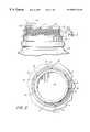
- FIG. 5is a perspective view of the cap of FIG. 3 and 4 of the drawings positioned on the upper portion of the container of FIG. 1 of the drawings with a portion of the combined tear skirt and flexible ratchet strip partially tom away therefrom.
- a portion of a blow molded jug or the likehas a neck 11 of a first diameter including at least two groups of vertically fastening configurations 12 spaced circumferentially thereon which define a shoulder 12 A.
- the neck of the container above the portion 12is a cylindrical portion 13 with a plurality, preferably seven, of horizontally and vertically annular spaced threads 14 , 15 , and 16 .
- the upper horizontally spaced ends of the remaining annular spiral threadsare indicated by the numerals 17 , 18 , 19 , and 20 .
- the annular spiral threads 14 - 20define three snap thread portions 16 B, 17 B, and 18 B therebetween.
- FIG. 2 of the drawingsthe top plan view of the neck finish of FIG. 1 illustrates the lead-in ends of the seven circumferentially and vertically spaced annular spiral threads 14 - 20 respectively and wherein the lead-in ends as shown in FIG. 2 of the drawings are spaced circumferentially with respect to one another around the neck finish of the tubular portion of the neck 13 .
- the vertical fastening configurations 12may be seen to comprise two groups of ratchet teeth which are preferably positioned on the opposite sides of the neck portion 13 although the other groupings of the vertical fastening configurations 12 may be used if desired.
- multiple thread patterns 14 A through 20 A in the flexible capregister with the circumferentially and vertically spaced multiple spiral thread patterns hereinbefore described in connections with FIGS. 1 and 2.
- the capcomprises a top portion 21 having an annular depending wall 22 integrally joined to the peripheral edge of the top 21 .
- the capis provided with a downturned annular sealing flange 23 depending from the bottom of the top 21 of the cap and the bottom edge of the depending annular wall 22 comprises a narrow outturned rib 24 .
- a tear skirt 25 of a slightly larger diameter than the rib 24is formed with its inner surface having a continuous ratchet tooth configuration 26 , the innermost upper corners of each of the ratchet teeth 26 comprise connecting members 27 by which the tear skirt 25 is integrally attached to the lower peripheral edge of the narrow outturned rib 24 . It will be seen that the innermost upper corners of each of the ratchet teeth 26 which comprise the connecting members 27 are spaced circumferentially so as to leave a plurality of openings 28 that also appear in the left hand portion of the cap as seen in FIG. 5 of the drawings.
- a cap portion 40can be seen in broken lines adjacent the neck 11 prior to registration with the respective thread patterns 14 A on the flexible cap in initial contact with the respective snap thread portion 16 B of the neck 11 as hereinbefore described.
- the cap and neck 11are not prepositioned before capping, the random position of the initial point of thread registration and “multiple snaps” of same, the cap once engaged while achieving a fluid seal with the neck 11 , may not be fully threaded and would require 1 ⁇ 8th or more turn to achieve full thread engagement against the neck should 12 A as seen in FIG. 5 .
- the snap, twist on, twist off tamper indicating flexible capis illustrated engaged on the neck finish of the cylindrical portion of the neck 13 of the container.
- the tear skirt 25is illustrated partially separated from the annular depending wall 22 of the cap wherein the continuous ratchet teeth 26 are separated from their engagement with the lower peripheral edge of the narrow outturned rib 24 which defines the lower edge of the annular depending wall 22 .
- the continuous ratchet teeth 26 of the flexible tear skirt 25are shown partially disengaged from one of the two groups of ratchet teeth comprising the fastening configurations 12 on the neck 11 of the container 10 .
- a pull tab 29is freed from a vertical tear line 30 and moved outwardly as illustrated.
- the tear skirt 25which comprises the elongated ratchet strip with the ratchet teeth 26 is joined at one of its ends 31 to the tear tab 29 and its other end terminates in the vertical tear line 30 .
- the tear skirt 25 in its as formed and in use position as best seen in FIG. 3is positioned vertically and it will also be seen that its lower edge is provided with an outturned flange 32 which will engage and rest on the portion of the blow molded jug 10 immediately below the neck portion 11 .
- the snap twist on, twist off tamper indicating flexible cap for blow molded jugs or the like disclosed hereinhas several points of novelty by reason of the continuous ratchet teeth configurations formed by the ratchet teeth 26 on the inner surface of the tear skirt 25 of the cap and the attachment of the tear skirt 25 to the lower surface of the outturned narrow rib 24 which comprises the slightly widened lower edge of the annular depending wall 22 of the cap.
- the plurality of horizontally and vertically spaced annular spiral threadsdefining three snap thread portions 16 B- 18 B within to initial sealing engagement of the cap to the neck with the required selective turn of the cap after sealing to a full thread engagement if required.
Landscapes
- Engineering & Computer Science (AREA)
- Mechanical Engineering (AREA)
- Ceramic Engineering (AREA)
- Closures For Containers (AREA)
Abstract
Description
Claims (20)
Priority Applications (1)
| Application Number | Priority Date | Filing Date | Title |
|---|---|---|---|
| US08/621,207USRE37243E1 (en) | 1993-03-24 | 1996-03-22 | Neck finish for a container and a matching registering multiple thread pattern in a flexible cap for engagement on said neck finish |
Applications Claiming Priority (3)
| Application Number | Priority Date | Filing Date | Title |
|---|---|---|---|
| US08/036,277US5307946A (en) | 1993-03-24 | 1993-03-24 | Neck finish for a container and a matching registering multiple thread pattern in a flexible cap for engagement on neck said finish |
| US08/113,064US5480045A (en) | 1993-03-24 | 1993-08-30 | Neck finish for a container and a matching registering multiple thread pattern in a flexible cap for engagement on said neck finish |
| US08/621,207USRE37243E1 (en) | 1993-03-24 | 1996-03-22 | Neck finish for a container and a matching registering multiple thread pattern in a flexible cap for engagement on said neck finish |
Related Parent Applications (1)
| Application Number | Title | Priority Date | Filing Date |
|---|---|---|---|
| US08/113,064ReissueUS5480045A (en) | 1993-03-24 | 1993-08-30 | Neck finish for a container and a matching registering multiple thread pattern in a flexible cap for engagement on said neck finish |
Publications (1)
| Publication Number | Publication Date |
|---|---|
| USRE37243E1true USRE37243E1 (en) | 2001-06-26 |
Family
ID=26713006
Family Applications (1)
| Application Number | Title | Priority Date | Filing Date |
|---|---|---|---|
| US08/621,207Expired - LifetimeUSRE37243E1 (en) | 1993-03-24 | 1996-03-22 | Neck finish for a container and a matching registering multiple thread pattern in a flexible cap for engagement on said neck finish |
Country Status (1)
| Country | Link |
|---|---|
| US (1) | USRE37243E1 (en) |
Cited By (6)
| Publication number | Priority date | Publication date | Assignee | Title |
|---|---|---|---|---|
| US20020037338A1 (en)* | 2000-07-24 | 2002-03-28 | Lisch G. David | Apparatus for stabilizing bottle upon demolding |
| US6754965B1 (en)* | 2000-11-28 | 2004-06-29 | Len C. Kretchman | Integrated sandwich crimping tool |
| US20050263476A1 (en)* | 2004-05-25 | 2005-12-01 | Cks Packaging, Inc. | Finish for injection blow molded container |
| USD732391S1 (en)* | 2012-02-10 | 2015-06-23 | Silgan Plastics Llc | Container with ribbed neck |
| US11090226B2 (en)* | 2015-04-17 | 2021-08-17 | Centre Hospitalier Universitaire D'amiens-Picardie | Sealing device for making it possible to collect a composition, packaging assembly comprising such a sealing device, collection and packaging methods |
| US20220312933A1 (en)* | 2021-04-01 | 2022-10-06 | Jiangmen K.K. Plastic Factory Ltd. | Cosmetic container |
Citations (16)
| Publication number | Priority date | Publication date | Assignee | Title |
|---|---|---|---|---|
| US2162711A (en)* | 1936-03-31 | 1939-06-20 | Hamberger John | Tamperproof closure |
| US2162712A (en)* | 1936-07-09 | 1939-06-20 | Hamberger John | Container and closure therefor |
| US3650428A (en)* | 1970-04-09 | 1972-03-21 | V C A Corp | Tamperproof closure device |
| US3885696A (en)* | 1972-11-04 | 1975-05-27 | Heinrich Eberhardt | Closure construction for container with lid |
| US3980195A (en)* | 1974-11-18 | 1976-09-14 | Owens-Illinois, Inc. | Tamper-proof closure |
| US4298129A (en)* | 1980-05-02 | 1981-11-03 | Morton Stull | Childproof, snap-on, twist-off safety cap and container |
| US4354609A (en)* | 1980-01-09 | 1982-10-19 | Hidding Walter E | Snap-on tamperproof bottle cap |
| GB2114553A (en)* | 1982-02-11 | 1983-08-24 | Guala Angelo Spa | Security closure for blow-moulded plastics containers |
| US4402415A (en)* | 1980-10-17 | 1983-09-06 | U. G. Closures & Plastics Limited | Integrally sealed container with cap |
| US4418828A (en)* | 1981-07-24 | 1983-12-06 | H-C Industries, Inc. | Plastic closure with mechanical pilfer band |
| US4497765A (en)* | 1979-09-21 | 1985-02-05 | H-C Industries, Inc. | Process for making a closure |
| US4534480A (en)* | 1984-06-01 | 1985-08-13 | Sun Coast Plastics, Inc. | Tamper evident closure |
| US4561553A (en)* | 1985-01-22 | 1985-12-31 | Northern Engineering And Plastics Corp. | Snap on twist off tamper-proof closure for containers |
| US4589561A (en)* | 1985-01-11 | 1986-05-20 | Northern Engineering And Plastics Corp. | Tamper-proof closure for containers |
| US4660053A (en)* | 1984-08-31 | 1987-04-21 | Kabushiki Kaisha Toshiba | Thermal transfer recording apparatus |
| US5213224A (en)* | 1990-08-09 | 1993-05-25 | Portola Packaging, Inc. | Snap-on, screw-off cap and container neck |
- 1996
- 1996-03-22USUS08/621,207patent/USRE37243E1/ennot_activeExpired - Lifetime
Patent Citations (16)
| Publication number | Priority date | Publication date | Assignee | Title |
|---|---|---|---|---|
| US2162711A (en)* | 1936-03-31 | 1939-06-20 | Hamberger John | Tamperproof closure |
| US2162712A (en)* | 1936-07-09 | 1939-06-20 | Hamberger John | Container and closure therefor |
| US3650428A (en)* | 1970-04-09 | 1972-03-21 | V C A Corp | Tamperproof closure device |
| US3885696A (en)* | 1972-11-04 | 1975-05-27 | Heinrich Eberhardt | Closure construction for container with lid |
| US3980195A (en)* | 1974-11-18 | 1976-09-14 | Owens-Illinois, Inc. | Tamper-proof closure |
| US4497765A (en)* | 1979-09-21 | 1985-02-05 | H-C Industries, Inc. | Process for making a closure |
| US4354609A (en)* | 1980-01-09 | 1982-10-19 | Hidding Walter E | Snap-on tamperproof bottle cap |
| US4298129A (en)* | 1980-05-02 | 1981-11-03 | Morton Stull | Childproof, snap-on, twist-off safety cap and container |
| US4402415A (en)* | 1980-10-17 | 1983-09-06 | U. G. Closures & Plastics Limited | Integrally sealed container with cap |
| US4418828A (en)* | 1981-07-24 | 1983-12-06 | H-C Industries, Inc. | Plastic closure with mechanical pilfer band |
| GB2114553A (en)* | 1982-02-11 | 1983-08-24 | Guala Angelo Spa | Security closure for blow-moulded plastics containers |
| US4534480A (en)* | 1984-06-01 | 1985-08-13 | Sun Coast Plastics, Inc. | Tamper evident closure |
| US4660053A (en)* | 1984-08-31 | 1987-04-21 | Kabushiki Kaisha Toshiba | Thermal transfer recording apparatus |
| US4589561A (en)* | 1985-01-11 | 1986-05-20 | Northern Engineering And Plastics Corp. | Tamper-proof closure for containers |
| US4561553A (en)* | 1985-01-22 | 1985-12-31 | Northern Engineering And Plastics Corp. | Snap on twist off tamper-proof closure for containers |
| US5213224A (en)* | 1990-08-09 | 1993-05-25 | Portola Packaging, Inc. | Snap-on, screw-off cap and container neck |
Cited By (7)
| Publication number | Priority date | Publication date | Assignee | Title |
|---|---|---|---|---|
| US20020037338A1 (en)* | 2000-07-24 | 2002-03-28 | Lisch G. David | Apparatus for stabilizing bottle upon demolding |
| US6709624B2 (en)* | 2000-07-24 | 2004-03-23 | Schmalbach-Lubeca Ag | Apparatus for stabilizing bottle upon demolding |
| US6754965B1 (en)* | 2000-11-28 | 2004-06-29 | Len C. Kretchman | Integrated sandwich crimping tool |
| US20050263476A1 (en)* | 2004-05-25 | 2005-12-01 | Cks Packaging, Inc. | Finish for injection blow molded container |
| USD732391S1 (en)* | 2012-02-10 | 2015-06-23 | Silgan Plastics Llc | Container with ribbed neck |
| US11090226B2 (en)* | 2015-04-17 | 2021-08-17 | Centre Hospitalier Universitaire D'amiens-Picardie | Sealing device for making it possible to collect a composition, packaging assembly comprising such a sealing device, collection and packaging methods |
| US20220312933A1 (en)* | 2021-04-01 | 2022-10-06 | Jiangmen K.K. Plastic Factory Ltd. | Cosmetic container |
Similar Documents
| Publication | Publication Date | Title |
|---|---|---|
| US5480045A (en) | Neck finish for a container and a matching registering multiple thread pattern in a flexible cap for engagement on said neck finish | |
| US5307946A (en) | Neck finish for a container and a matching registering multiple thread pattern in a flexible cap for engagement on neck said finish | |
| US5285912A (en) | Snap on pull off tamper indicating flexible cap and neck configuration | |
| US4561553A (en) | Snap on twist off tamper-proof closure for containers | |
| US4966292A (en) | Cap and neck finish for a wide mouth container | |
| US4667839A (en) | Snap on tamper indicating closure for containers | |
| US4658977A (en) | Snap on twist off tamper-proof closure for containers | |
| US5373955A (en) | Neck finish for a wide mouth container | |
| US4589561A (en) | Tamper-proof closure for containers | |
| US5560504A (en) | Snap on pull off tamper indicating flexible cap and neck configuration | |
| US3984021A (en) | Safety closure container | |
| US4432461A (en) | Tamper indicating package | |
| CA1101796A (en) | Tamperproof molded package | |
| EP1025015B1 (en) | Tamper evident bottle cap | |
| CN1082479C (en) | Plastic Jaw Caps | |
| US5450973A (en) | Tamper-evident closure apparatus | |
| US4676389A (en) | Tamper-resistant container closure | |
| US5050754A (en) | Cap for a neck finish on a wide mouth container | |
| US6003701A (en) | Tamper resistant bottle cap and neck | |
| US4687114A (en) | Tamper indicating closure for containers | |
| US5036991A (en) | Tamper evident-cap for containers | |
| US3934744A (en) | Closure assembly | |
| US5950849A (en) | Container closure with ribbed enlarged grasping region | |
| US6305579B1 (en) | Snap-on screw-off closure | |
| US20050269373A1 (en) | Cover for dispensing closure with pressure actuated valve |
Legal Events
| Date | Code | Title | Description |
|---|---|---|---|
| AS | Assignment | Owner name:HELLER FINANCIAL, ILLINOIS Free format text:SECURITY INTEREST;ASSIGNOR:PORTOLA PACKAGING, INC.;REEL/FRAME:011571/0158 Effective date:20000929 | |
| FPAY | Fee payment | Year of fee payment:8 | |
| REMI | Maintenance fee reminder mailed | ||
| FPAY | Fee payment | Year of fee payment:12 | |
| SULP | Surcharge for late payment | Year of fee payment:11 | |
| AS | Assignment | Owner name:WAYZATA INVESTMENT PARTNERS LLC,MINNESOTA Free format text:SECURITY AGREEMENT;ASSIGNOR:PORTOLA PACKAGING, INC.;REEL/FRAME:020963/0731 Effective date:20080414 Owner name:WAYZATA INVESTMENT PARTNERS LLC, MINNESOTA Free format text:SECURITY AGREEMENT;ASSIGNOR:PORTOLA PACKAGING, INC.;REEL/FRAME:020963/0731 Effective date:20080414 | |
| AS | Assignment | Owner name:PORTOLA PACKAGING, INC., ILLINOIS Free format text:RELEASE BY SECURED PARTY;ASSIGNOR:GENERAL ELECTRIC CAPITAL CORPORATION, SUCCESSOR-IN-INTEREST TO HELLER FINANCIAL INC., AS AGENT;REEL/FRAME:021890/0725 Effective date:20081125 Owner name:PORTOLA PACKAGING, INC.,ILLINOIS Free format text:RELEASE BY SECURED PARTY;ASSIGNOR:WAYZATA INVESTMENT PARTNERS LLC;REEL/FRAME:021890/0715 Effective date:20081125 Owner name:PORTOLA PACKAGING, INC., ILLINOIS Free format text:RELEASE BY SECURED PARTY;ASSIGNOR:WAYZATA INVESTMENT PARTNERS LLC;REEL/FRAME:021890/0715 Effective date:20081125 | |
| AS | Assignment | Owner name:WELLS FARGO FOOTHILL, LLC, AS AGENT,MASSACHUSETTS Free format text:SECURITY AGREEMENT;ASSIGNOR:PORTOLA PACKAGING, INC.;REEL/FRAME:021912/0088 Effective date:20081125 Owner name:WELLS FARGO FOOTHILL, LLC, AS AGENT, MASSACHUSETTS Free format text:SECURITY AGREEMENT;ASSIGNOR:PORTOLA PACKAGING, INC.;REEL/FRAME:021912/0088 Effective date:20081125 | |
| AS | Assignment | Owner name:WAYZATA INVESTMENT PARTNERS, LLC (AGENT FOR THE SU Free format text:SECURITY AGREEMENT;ASSIGNOR:PORTOLA ALLIED TOOL, INC.;REEL/FRAME:021965/0621 Effective date:20081125 | |
| AS | Assignment | Owner name:GENERAL ELECTRIC CAPITAL CORPORATION, AS US AGENT Free format text:SECURITY AGREEMENT;ASSIGNOR:PORTOLA PACKAGING, INC.;REEL/FRAME:024933/0037 Effective date:20100902 | |
| AS | Assignment | Owner name:PORTOLA PACKAGING, INC., ILLINOIS Free format text:RELEASE BY SECURED PARTY;ASSIGNOR:WELLS FARGO CAPITAL FINANCE, LLC, AS AGENT, (F/K/A WELLS FARGO FOOTHILL, LLC, AS AGENT);REEL/FRAME:024933/0821 Effective date:20100902 | |
| AS | Assignment | Owner name:PORTOLA PACKAGING, INC., ILLINOIS Free format text:RELEASE BY SECURED PARTY;ASSIGNOR:GENERAL ELECTRIC CAPITAL CORPORATION, AS U.S. AGENT AND CANADIAN AGENT;REEL/FRAME:031510/0065 Effective date:20131022 | |
| AS | Assignment | Owner name:PORTOLA PACKAGING, INC., ILLINOIS Free format text:RELEASE BY SECURED PARTY;ASSIGNOR:WAYZATA INVESTMENT PARTNERS LLC, AS AGENT;REEL/FRAME:031637/0520 Effective date:20131022 |