USRE36972E - Electrolytic cell for generating sterilization solutions having increased ozone content - Google Patents
Electrolytic cell for generating sterilization solutions having increased ozone contentDownload PDFInfo
- Publication number
- USRE36972E USRE36972EUS08/787,160US78716097AUSRE36972EUS RE36972 EUSRE36972 EUS RE36972EUS 78716097 AUS78716097 AUS 78716097AUS RE36972 EUSRE36972 EUS RE36972E
- Authority
- US
- United States
- Prior art keywords
- anode
- electrolytic solution
- flow
- ozone
- cathode
- Prior art date
- Legal status (The legal status is an assumption and is not a legal conclusion. Google has not performed a legal analysis and makes no representation as to the accuracy of the status listed.)
- Expired - Lifetime
Links
Images


Classifications
- C—CHEMISTRY; METALLURGY
- C02—TREATMENT OF WATER, WASTE WATER, SEWAGE, OR SLUDGE
- C02F—TREATMENT OF WATER, WASTE WATER, SEWAGE, OR SLUDGE
- C02F1/00—Treatment of water, waste water, or sewage
- C02F1/72—Treatment of water, waste water, or sewage by oxidation
- C02F1/76—Treatment of water, waste water, or sewage by oxidation with halogens or compounds of halogens
- B—PERFORMING OPERATIONS; TRANSPORTING
- B01—PHYSICAL OR CHEMICAL PROCESSES OR APPARATUS IN GENERAL
- B01J—CHEMICAL OR PHYSICAL PROCESSES, e.g. CATALYSIS OR COLLOID CHEMISTRY; THEIR RELEVANT APPARATUS
- B01J19/00—Chemical, physical or physico-chemical processes in general; Their relevant apparatus
- B01J19/08—Processes employing the direct application of electric or wave energy, or particle radiation; Apparatus therefor
- B01J19/12—Processes employing the direct application of electric or wave energy, or particle radiation; Apparatus therefor employing electromagnetic waves
- C—CHEMISTRY; METALLURGY
- C02—TREATMENT OF WATER, WASTE WATER, SEWAGE, OR SLUDGE
- C02F—TREATMENT OF WATER, WASTE WATER, SEWAGE, OR SLUDGE
- C02F1/00—Treatment of water, waste water, or sewage
- C02F1/46—Treatment of water, waste water, or sewage by electrochemical methods
- C02F1/461—Treatment of water, waste water, or sewage by electrochemical methods by electrolysis
- C02F1/467—Treatment of water, waste water, or sewage by electrochemical methods by electrolysis by electrochemical disinfection; by electrooxydation or by electroreduction
- C02F1/4672—Treatment of water, waste water, or sewage by electrochemical methods by electrolysis by electrochemical disinfection; by electrooxydation or by electroreduction by electrooxydation
- C—CHEMISTRY; METALLURGY
- C02—TREATMENT OF WATER, WASTE WATER, SEWAGE, OR SLUDGE
- C02F—TREATMENT OF WATER, WASTE WATER, SEWAGE, OR SLUDGE
- C02F1/00—Treatment of water, waste water, or sewage
- C02F1/72—Treatment of water, waste water, or sewage by oxidation
- C02F1/78—Treatment of water, waste water, or sewage by oxidation with ozone
- C—CHEMISTRY; METALLURGY
- C02—TREATMENT OF WATER, WASTE WATER, SEWAGE, OR SLUDGE
- C02F—TREATMENT OF WATER, WASTE WATER, SEWAGE, OR SLUDGE
- C02F1/00—Treatment of water, waste water, or sewage
- C02F1/46—Treatment of water, waste water, or sewage by electrochemical methods
- C02F1/461—Treatment of water, waste water, or sewage by electrochemical methods by electrolysis
- C02F1/46104—Devices therefor; Their operating or servicing
- C02F1/46109—Electrodes
- C02F2001/46133—Electrodes characterised by the material
- C—CHEMISTRY; METALLURGY
- C02—TREATMENT OF WATER, WASTE WATER, SEWAGE, OR SLUDGE
- C02F—TREATMENT OF WATER, WASTE WATER, SEWAGE, OR SLUDGE
- C02F2201/00—Apparatus for treatment of water, waste water or sewage
- C02F2201/46—Apparatus for electrochemical processes
- C02F2201/461—Electrolysis apparatus
- C02F2201/46105—Details relating to the electrolytic devices
- C02F2201/4611—Fluid flow
- C—CHEMISTRY; METALLURGY
- C02—TREATMENT OF WATER, WASTE WATER, SEWAGE, OR SLUDGE
- C02F—TREATMENT OF WATER, WASTE WATER, SEWAGE, OR SLUDGE
- C02F2201/00—Apparatus for treatment of water, waste water or sewage
- C02F2201/46—Apparatus for electrochemical processes
- C02F2201/461—Electrolysis apparatus
- C02F2201/46105—Details relating to the electrolytic devices
- C02F2201/4612—Controlling or monitoring
- C02F2201/46125—Electrical variables
- C—CHEMISTRY; METALLURGY
- C02—TREATMENT OF WATER, WASTE WATER, SEWAGE, OR SLUDGE
- C02F—TREATMENT OF WATER, WASTE WATER, SEWAGE, OR SLUDGE
- C02F2201/00—Apparatus for treatment of water, waste water or sewage
- C02F2201/46—Apparatus for electrochemical processes
- C02F2201/461—Electrolysis apparatus
- C02F2201/46105—Details relating to the electrolytic devices
- C02F2201/4612—Controlling or monitoring
- C02F2201/46145—Fluid flow
- C—CHEMISTRY; METALLURGY
- C02—TREATMENT OF WATER, WASTE WATER, SEWAGE, OR SLUDGE
- C02F—TREATMENT OF WATER, WASTE WATER, SEWAGE, OR SLUDGE
- C02F2201/00—Apparatus for treatment of water, waste water or sewage
- C02F2201/46—Apparatus for electrochemical processes
- C02F2201/461—Electrolysis apparatus
- C02F2201/46105—Details relating to the electrolytic devices
- C02F2201/4618—Supplying or removing reactants or electrolyte
- C—CHEMISTRY; METALLURGY
- C02—TREATMENT OF WATER, WASTE WATER, SEWAGE, OR SLUDGE
- C02F—TREATMENT OF WATER, WASTE WATER, SEWAGE, OR SLUDGE
- C02F2201/00—Apparatus for treatment of water, waste water or sewage
- C02F2201/78—Details relating to ozone treatment devices
- C02F2201/782—Ozone generators
- C—CHEMISTRY; METALLURGY
- C02—TREATMENT OF WATER, WASTE WATER, SEWAGE, OR SLUDGE
- C02F—TREATMENT OF WATER, WASTE WATER, SEWAGE, OR SLUDGE
- C02F2209/00—Controlling or monitoring parameters in water treatment
- C02F2209/06—Controlling or monitoring parameters in water treatment pH
- C—CHEMISTRY; METALLURGY
- C02—TREATMENT OF WATER, WASTE WATER, SEWAGE, OR SLUDGE
- C02F—TREATMENT OF WATER, WASTE WATER, SEWAGE, OR SLUDGE
- C02F2301/00—General aspects of water treatment
- C02F2301/02—Fluid flow conditions
- C02F2301/022—Laminar
Definitions
- the present inventionrelates to water sterilization equipment, and more particularly, to an electrolytic cell for generating oxidant solutions that include ozone.
- Maintaining the sterility of drinking water suppliesis a major factor in reducing the health risks to the human population. While large metropolitan water systems can make use of highly toxic chlorine gas for sterilizing drinking water, such systems are impractical in remote locations which lack highly trained personnel and the equipment to maintain the systems. To be effective in rural settings, a system must be capable of running for long periods of time with little or no maintenance. In addition, the raw materials required by the system must be readily available.
- the most effective mixed oxidant streamhas been found to be an oxidant stream in which the ratio of ozone and H 2 O 2 to the chlorine based compounds is maximized.
- the ozone and H 2 O 2 oxidantsprovide a more palatable drinking water supply.
- the present inventioncomprises an apparatus for generating a mixed oxidant stream including ozone, as well as chlorine based oxidants.
- the apparatusincludes a flow chamber having two substantially planar walls which form the anode and cathode of an electrical circuit. A DC electric potential is maintained between the anode and cathode. An electrolytic solution is caused to flow between the anode and cathode surfaces. This stream is subsequently divided into cathode and anode streams. The anode stream provides the mixed oxidant stream in question.
- the flow rate through the apparatusdetermines the ratio of the various oxidants in the anode stream. This flow rate is adjusted with the aid of a sensor that measures a parameter which is correlated with ozone production to maintain optimum ozone production.
- the zone between the anode and cathodemust be defined such that an electrochemical interaction zone bounded by the anode and cathode exists that has a shape such that electrolytic solution caused to flow through said interaction zone has substantially the same residence time in said interaction zone independent of the path taken through the interaction zone.
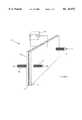
- FIG. 1is a prospective view of an electrolytic cell according to the present invention.
- FIG. 2is a side view of an electrolytic cell according to the present invention.
- FIG. 3is a cross-sectional view of an electrolytic cell according to the present invention.
- FIG. 4is a top view of a cell having a more optimally defined electrochemical interaction zone.
- FIG. 5is a block diagram of a water purification system according to the present invention.
- Electrolytic cell 10includes an anode 12 and a cathode 14 which are separated by an insulating gasket 16 thereby forming a flow chamber 24 through which a salt solution is passed.
- the salt solutionis introduced through an input port 18 and exits through an anode port 20 and a cathode port 22.
- a DC voltageis maintained between anode 12 and cathode 14 with the aid of a power source 24.
- Anode 12 and cathode 14are preferably constructed from titanium.
- anode 12preferably includes a Group VIII metal for the reasons discussed below.
- the flow of salt solutionis divided by an extension of gasket 25 into anode and cathode output streams which exit through anode port 20 and cathode port 22, respectively.
- the flow in chamber 24is laminar in nature. As the salt solution traverse the chamber 24, the pH of the solution changes. The portion of the salt solution that is adjacent to anode 12 decreases in pH, while the portion of the salt solution that is adjacent to cathode 14 increases in pH.
- the solution leaving the anode portincludes ozone and various chlorine containing oxidants.
- This solutionwill be referred to as the anode stream in the following discussion.
- the solution leaving the cathode portwill be referred to as the cathode stream.
- the division of the input stream from input port 18 into the anode and cathode streamsis aided by an extension of gasket 16 which forms a flow separator 25. As will be explained in more detail below, the shape and location of separator 25 is a significant factor in the concentration of ozone in the anode stream.
- the anode streamis added to the water supply to be sterilized.
- the anode streamis preferred because it contains higher concentrations of desired oxidants and because it has an acidic pH. Regulatory requirements governing drinking water dictate that the final drinking water supply be neutral or acidic. In addition, the germicidal effects of the mixed oxidants are increased in acidic environments.
- the specific oxidants that are generated in the anode stream as it progresses through the celldepend on the pH of the solution at the corresponding point in the cell and on the material from which the anode is constructed.
- the concentrations of ozone produced in the electrolytic celldepend much more sensitively on these factors than do the concentrations of the chlorine based compounds.
- ozoneis produced over a relatively narrow range of pH values. At pH values above the optimum, little ozone is produced. At pH values below the optimum, the ozone is converted to less effective compounds and radicals.
- the ozone productionis also dependent on the material from which the anode is constructed.
- ozone productionis catalyzed by Group VIII metals such as platinum, iridium, rhodium, or ruthenium.
- Group VIII metalssuch as platinum, iridium, rhodium, or ruthenium.
- these metalsare highly resistant to corrosion and do not dissolve easily.
- the preferred embodiment of anode 12 in electrolytic cell 10is constructed from titanium that has been plated with iridium.
- electrolytes other than NaClmay be used. A number of possible combinations of salts and materials are discussed in U.S. Pat. No. 4,761,208 discussed above.
- the production of the chlorine based oxidantsis far less sensitive to pH and anode construction. It is this difference in sensitivity which is utilized in the present invention to provide increased ratios of ozone to chlorine based compounds.
- an operating parameter that effects ozone productioncan be altered until an ozone sensor in the anode stream indicates that optimum ozone production is being achieved.
- some other measurement that is related to the ozone productionmay be used in the servo loop.
- ozone productionFor any given salt concentration and flow rate of the salt solution through the electrolytic cell, there is a narrow pH range in which ozone production will be maximized. Hence, either ozone production or pH may be used to run the servo loop. Since pH electrodes are inexpensive and reliable, a servo loop based on pH provides an attractive alternative to a servo loop based on ozone.
- optimum pH rangeis generated just before the salt solution reaches the location of separator 25, i.e., in region 27 shown in FIG. 3, the ozone production of electrolytic cell 10 will be optimized. If the optimum pH range is not obtained by the time the salt solution reaches region 27, too little ozone will be generated. If, on the other hand, the optimum pH range is reached well before the salt solution reaches region 27, the pH of the salt solution along the anode in region 27 will be significantly below the optimum pH. As a result, the ozone generated in the region of optimum pH will be lost in the below optimum pH conditions in region 27.
- separator 25is an electrical insulator. As a result, further electrolytic reactions of the salt solution at anode 12 and cathode 14 in the regions between the end of separator 25 and ports 20 and 22 are negligible.
- the anode streameffectively represents a sampling of the salt solution at the end of separator 25.
- the ozone productionis related to the pH of the electrolyte at the location of the separator. Hence, it is important that the shape of the separator be chosen such that the pH of the electrolyte at the anode surface is substantially constant along the edge of separator 25. If this condition is not met, the anode stream will be derived from regions of differing pH. Those regions that have pH's outside the optimum will contribute less ozone to the anode stream; hence, less than optimal ozone production will be obtained.
- the pH at any point in the celldepends on the flow pattern of the electrolytic solution between input port 18 and the point in question. Consider the points located along the anode. As the electrolytic solution progresses through the electrolytic cell, the pH decreases as noted above. The amount of decrease will depend on the amount of time the electrolyte has spent in contact with the anode. This, in turn, is related to the transit time of the electrolyte from the point at which it encounters sufficient electric field to undergo significant electrochemical reactions to the point in question.
- the optimum shape for the edge of separator 25is that which guarantees that fluid at each point along the edge of the separator has spend substantially the same time in contact with the anode in that portion of the flow chamber in which significant electrochemical interactions take place, i.e., interactions that significantly change the pH of the electrolyte.
- flow chamber 24is substantially rectilinear in shape with small openings for input port 18 and output ports 20 and 22.
- Such cell designsare particularly easy to construct at minimal cost.
- the flow within the chamber itselfis not rectilinear because of the need for the fluid to "fan-out" from the input port and be recollected at the output ports.
- a rectilinear flow regioncan, however, be defined within this region by introducing a rectilinear insulator at the input end of the flow chamber. Such an arrangement is shown in FIG. 4 at 150.
- FIG. 4is a top view of a flow cell according to the present invention illustrating the location and shape of two insulating members for limiting the electrochemical interaction area to those regions of the cell in which the flow is rectilinear.
- the insulator 151may be attached to the electrode which is opposite the input port 160. Insulator 151 serves the function of preventing current flow through the electrolyte in the region of the flow chamber at which the fluid is still fanning out.
- Insulator 152is a separator analogous to separator 25 shown above. Insulator 152 divides the flow into anode and cathode streams and shields the portion of the flow in which the fluid is collected into the two streams from electrochemical interactions.
- the remaining region 155is a region of parallel flow in which the transit time along all paths is essentially the same. This region is not shielded by the insulator; hence, the electrochemical reactions described above occur in this region.
- the input insulatormay be omitted and non-linearities introduced into the shape of separator 25 to assure that the fluid traversing the various portions of the boundary of separator 25 had spent equal time in contact with the anode surface.
- Alternative insulator designswhich provide an electrochemical interaction region in which all portions of the electrolyte flow have the same residency time will be apparent to those skilled in the art.
- the goal of the optimization process of the present inventionis to assure that the various structural and operating parameters of electrolytic cell 10 are chosen such that the optimum pH range for ozone production occurs at the end of separator 25.
- This optimizationmay be accomplished by a servo mechanism that operates on any of a number of operating parameters.
- the preferred parameteris the flow rate of the salt solution through the cell which may be adjusted by adjusting the pressure of the salt solution at port 18. As the pressure is increased, the flow rate increases and the drop in pH between input port 18 and region 25 is decreased. Similarly, if the pressure is decreased, the salt solution will spend more time in contact with the anode which results in a decrease in the pH of the anode stream.
- the voltage across electrolytic cell 10may be adjusted to optimize the pH of the anode stream.
- the rate of reactionalso increases thereby reducing the pH of the anode stream.
- increasing the operating voltage across electrolytic cell 10results in other problems.
- the production of various gaseous productssuch as H 2 and O 2 increases with increased voltage.
- the H 2poses an explosion hazard.
- these productsare less efficient from a germicidal prospective.
- the rate at which the coatings on the inner surface of the anode are erodedalso increases rapidly with increasing voltage; hence, the lifetime of the cell is significantly decreased if the operating voltage is increased. For these reasons, adjustment of operating voltage to obtain optimum pH in the anode stream is not preferred.
- the concentration of saltcould be adjusted to optimize the anode stream pH.
- the equipment for providing variable mixing of solutionis more complex, and hence, to be avoided.
- the amount of ozone producedis also determined by the coating material used on the anode.
- This coating materialrepresents a significant portion of the cost of electrolytic cell 10; hence, it is advantageous to minimize the area that must be plated.
- the coated areamay be minimized by limiting the Group VIII catalyst to region 27 shown in FIG. 3. This arrangement allows a significantly thicker coating to be provided for the same cost. As a result, an electrolytic cell with increased lifetime is obtained.
- electrolytic cell 10also effects the ozone content of the anode stream.
- electrolytic cell 10is mounted vertically with anode port 20 above input port 18, the concentration of ozone in the anode stream is significantly increased.
- FIG. 4A block diagram of a water purification system 200 utilizing an electrolytic cell 210 according to the present invention is shown in FIG. 4.
- Electrolytic cell 210is supplied with a brine solution from a salt reservoir 212 that provides brine at a pressure above some minimum design pressure.
- Reservoir 212preferably includes a storage tank that is mounted at a fixed distance above electrolytic cell 210. However, it will be apparent to those skilled in the art that a tank and pump arrangement will also provide the required functionality.
- a control valve 214is used to control the flow rate of the brine solution through electrolytic cell 210. Control valve 214 is operated by controller 210 which is connected to the output of sensor 215.
- Sensor 215measures the ozone concentration in the anode stream leaving port 208 or some other parameter that is correlated with ozone concentration, e.g. pH.
- the anode streamis combined at a predetermined ratio with water from a drinking water source 216 to generate a purified water stream. This mixing is accomplished with the aid of mixing valve 218.
Landscapes
- Chemical & Material Sciences (AREA)
- Organic Chemistry (AREA)
- Water Supply & Treatment (AREA)
- Life Sciences & Earth Sciences (AREA)
- Hydrology & Water Resources (AREA)
- Engineering & Computer Science (AREA)
- Environmental & Geological Engineering (AREA)
- Chemical Kinetics & Catalysis (AREA)
- General Chemical & Material Sciences (AREA)
- Electrochemistry (AREA)
- Electromagnetism (AREA)
- Physics & Mathematics (AREA)
- Health & Medical Sciences (AREA)
- General Health & Medical Sciences (AREA)
- Toxicology (AREA)
- Electrolytic Production Of Non-Metals, Compounds, Apparatuses Therefor (AREA)
- Treatment Of Water By Oxidation Or Reduction (AREA)
- Water Treatment By Electricity Or Magnetism (AREA)
- Physical Or Chemical Processes And Apparatus (AREA)
Abstract
Description
Claims (3)
Priority Applications (1)
| Application Number | Priority Date | Filing Date | Title |
|---|---|---|---|
| US08/787,160USRE36972E (en) | 1992-03-26 | 1997-01-23 | Electrolytic cell for generating sterilization solutions having increased ozone content |
Applications Claiming Priority (3)
| Application Number | Priority Date | Filing Date | Title |
|---|---|---|---|
| US07/857,731US5316740A (en) | 1992-03-26 | 1992-03-26 | Electrolytic cell for generating sterilization solutions having increased ozone content |
| US08/200,146US5385711A (en) | 1992-03-26 | 1994-02-23 | Electrolytic cell for generating sterilization solutions having increased ozone content |
| US08/787,160USRE36972E (en) | 1992-03-26 | 1997-01-23 | Electrolytic cell for generating sterilization solutions having increased ozone content |
Related Parent Applications (2)
| Application Number | Title | Priority Date | Filing Date |
|---|---|---|---|
| US07/857,731ContinuationUS5316740A (en) | 1992-03-26 | 1992-03-26 | Electrolytic cell for generating sterilization solutions having increased ozone content |
| US08/200,146ReissueUS5385711A (en) | 1992-03-26 | 1994-02-23 | Electrolytic cell for generating sterilization solutions having increased ozone content |
Publications (1)
| Publication Number | Publication Date |
|---|---|
| USRE36972Etrue USRE36972E (en) | 2000-11-28 |
Family
ID=25326629
Family Applications (3)
| Application Number | Title | Priority Date | Filing Date |
|---|---|---|---|
| US07/857,731Expired - LifetimeUS5316740A (en) | 1992-03-26 | 1992-03-26 | Electrolytic cell for generating sterilization solutions having increased ozone content |
| US08/200,146CeasedUS5385711A (en) | 1992-03-26 | 1994-02-23 | Electrolytic cell for generating sterilization solutions having increased ozone content |
| US08/787,160Expired - LifetimeUSRE36972E (en) | 1992-03-26 | 1997-01-23 | Electrolytic cell for generating sterilization solutions having increased ozone content |
Family Applications Before (2)
| Application Number | Title | Priority Date | Filing Date |
|---|---|---|---|
| US07/857,731Expired - LifetimeUS5316740A (en) | 1992-03-26 | 1992-03-26 | Electrolytic cell for generating sterilization solutions having increased ozone content |
| US08/200,146CeasedUS5385711A (en) | 1992-03-26 | 1994-02-23 | Electrolytic cell for generating sterilization solutions having increased ozone content |
Country Status (19)
| Country | Link |
|---|---|
| US (3) | US5316740A (en) |
| EP (1) | EP0632746B1 (en) |
| JP (1) | JP3051175B2 (en) |
| KR (1) | KR100220363B1 (en) |
| AR (1) | AR247765A1 (en) |
| AT (1) | ATE192944T1 (en) |
| AU (1) | AU667525B2 (en) |
| BR (1) | BR9306134A (en) |
| CA (1) | CA2130911C (en) |
| DE (1) | DE69328676T2 (en) |
| FI (1) | FI944424L (en) |
| HU (1) | HU218057B (en) |
| IL (1) | IL104989A0 (en) |
| MX (1) | MX9301712A (en) |
| MY (1) | MY109908A (en) |
| NO (1) | NO943412D0 (en) |
| RU (1) | RU2123069C1 (en) |
| TW (1) | TW210327B (en) |
| WO (1) | WO1993018854A1 (en) |
Cited By (26)
| Publication number | Priority date | Publication date | Assignee | Title |
|---|---|---|---|---|
| US20060157422A1 (en)* | 2003-11-13 | 2006-07-20 | Evgeniya Freydina | Water treatment system and method |
| US7147785B2 (en) | 2000-09-28 | 2006-12-12 | Usfilter Corporation | Electrodeionization device and methods of use |
| US7329358B2 (en) | 2004-05-27 | 2008-02-12 | Siemens Water Technologies Holding Corp. | Water treatment process |
| US7371319B2 (en) | 2002-10-23 | 2008-05-13 | Siemens Water Technologies Holding Corp. | Production of water for injection using reverse osmosis |
| US7563351B2 (en) | 2003-11-13 | 2009-07-21 | Siemens Water Technologies Holding Corp. | Water treatment system and method |
| US7572359B2 (en) | 2001-10-15 | 2009-08-11 | Siemens Water Technologies Holding Corp. | Apparatus for fluid purification and methods of manufacture and use thereof |
| US7582198B2 (en) | 2003-11-13 | 2009-09-01 | Siemens Water Technologies Holding Corp. | Water treatment system and method |
| US7604725B2 (en) | 2003-11-13 | 2009-10-20 | Siemens Water Technologies Holding Corp. | Water treatment system and method |
| US7604735B1 (en) | 1999-09-10 | 2009-10-20 | Barnes Ronald L | Combined chlorine and ozone generator sterilization system |
| US7744760B2 (en) | 2006-09-20 | 2010-06-29 | Siemens Water Technologies Corp. | Method and apparatus for desalination |
| US7846340B2 (en) | 2003-11-13 | 2010-12-07 | Siemens Water Technologies Corp. | Water treatment system and method |
| US7862700B2 (en) | 2003-11-13 | 2011-01-04 | Siemens Water Technologies Holding Corp. | Water treatment system and method |
| US20110024122A1 (en)* | 2008-03-12 | 2011-02-03 | M-I Drilling Fluids Uk Limited | Methods and systems of treating a wellbore |
| US8045849B2 (en) | 2005-06-01 | 2011-10-25 | Siemens Industry, Inc. | Water treatment system and process |
| US8377279B2 (en) | 2003-11-13 | 2013-02-19 | Siemens Industry, Inc. | Water treatment system and method |
| US8562810B2 (en) | 2011-07-26 | 2013-10-22 | Ecolab Usa Inc. | On site generation of alkalinity boost for ware washing applications |
| US8585882B2 (en) | 2007-11-30 | 2013-11-19 | Siemens Water Technologies Llc | Systems and methods for water treatment |
| US8658043B2 (en) | 2003-11-13 | 2014-02-25 | Siemens Water Technologies Llc | Water treatment system and method |
| US8671985B2 (en) | 2011-10-27 | 2014-03-18 | Pentair Residential Filtration, Llc | Control valve assembly |
| US8882972B2 (en) | 2011-07-19 | 2014-11-11 | Ecolab Usa Inc | Support of ion exchange membranes |
| US8961770B2 (en) | 2011-10-27 | 2015-02-24 | Pentair Residential Filtration, Llc | Controller and method of operation of a capacitive deionization system |
| US9010361B2 (en) | 2011-10-27 | 2015-04-21 | Pentair Residential Filtration, Llc | Control valve assembly |
| US9023185B2 (en) | 2006-06-22 | 2015-05-05 | Evoqua Water Technologies Llc | Low scale potential water treatment |
| US9637397B2 (en) | 2011-10-27 | 2017-05-02 | Pentair Residential Filtration, Llc | Ion removal using a capacitive deionization system |
| US9636715B1 (en) | 2013-04-08 | 2017-05-02 | Ronald L. Barnes | Sanitizing and cleaning process and method |
| US9695070B2 (en) | 2011-10-27 | 2017-07-04 | Pentair Residential Filtration, Llc | Regeneration of a capacitive deionization system |
Families Citing this family (42)
| Publication number | Priority date | Publication date | Assignee | Title |
|---|---|---|---|---|
| US5447630A (en)* | 1993-04-28 | 1995-09-05 | Rummler; John M. | Materials treatment process and apparatus |
| US5972196A (en)* | 1995-06-07 | 1999-10-26 | Lynntech, Inc. | Electrochemical production of ozone and hydrogen peroxide |
| CA2104355C (en)* | 1993-08-18 | 1997-06-17 | Ion I. Inculet | Method and apparatus for ozone generation and treatment of water |
| US6117285A (en)* | 1994-08-26 | 2000-09-12 | Medical Discoveries, Inc. | System for carrying out sterilization of equipment |
| US5507932A (en)* | 1994-08-26 | 1996-04-16 | Schlumberger Technology Corporation | Apparatus for electrolyzing fluids |
| DE19640839C2 (en)* | 1996-10-02 | 1999-08-26 | Fresenius Medical Care De Gmbh | Method and device for disinfecting a dialysis machine |
| DE19640840C2 (en)* | 1996-10-02 | 1999-08-26 | Fresenius Medical Care De Gmbh | Method for disinfecting a dialysis machine |
| US6576096B1 (en) | 1998-01-05 | 2003-06-10 | Lynntech International, Ltd. | Generation and delivery device for ozone gas and ozone dissolved in water |
| US5989407A (en) | 1997-03-31 | 1999-11-23 | Lynntech, Inc. | Generation and delivery device for ozone gas and ozone dissolved in water |
| US6287431B1 (en) | 1997-03-21 | 2001-09-11 | Lynntech International, Ltd. | Integrated ozone generator system |
| US6171551B1 (en)* | 1998-02-06 | 2001-01-09 | Steris Corporation | Electrolytic synthesis of peracetic acid and other oxidants |
| WO2001010215A1 (en) | 1999-08-05 | 2001-02-15 | Steris Inc. | Electrolytic synthesis of peracetic acid |
| CN1315738C (en) | 2000-12-12 | 2007-05-16 | 沃特皮克公司 | Device and method for generating and applying ozonated water |
| US7048842B2 (en)* | 2001-06-22 | 2006-05-23 | The Procter & Gamble Company | Electrolysis cell for generating chlorine dioxide |
| CA2434646C (en) | 2001-02-15 | 2011-08-23 | The Procter & Gamble Company | High efficiency electrolysis cell for generating oxidants in solutions |
| US7008523B2 (en)* | 2001-07-16 | 2006-03-07 | Miox Corporation | Electrolytic cell for surface and point of use disinfection |
| US7005075B2 (en)* | 2001-07-16 | 2006-02-28 | Miox Corporation | Gas drive electrolytic cell |
| CA2400775C (en) | 2002-08-28 | 2010-12-07 | Fatpower Inc. | Electrolyzer |
| WO2006033762A2 (en)* | 2004-08-19 | 2006-03-30 | Miox Corporation | Scented electrolysis product |
| CA2586588A1 (en)* | 2004-11-02 | 2006-05-11 | Hy-Drive Technologies Ltd. | Electrolysis cell electrolyte pumping system |
| US20060137973A1 (en)* | 2004-11-24 | 2006-06-29 | Miox Corporation | Device and method for instrument steralization |
| US20080116144A1 (en) | 2006-10-10 | 2008-05-22 | Spicer Randolph, Llc | Methods and compositions for reducing chlorine demand, decreasing disinfection by-products and controlling deposits in drinking water distribution systems |
| WO2008064180A1 (en)* | 2006-11-17 | 2008-05-29 | Miox Corporation | Water purification system |
| US20120048741A1 (en) | 2006-11-28 | 2012-03-01 | Miox Corporation | Electrolytic On-Site Generator |
| WO2008067411A2 (en)* | 2006-11-28 | 2008-06-05 | Miox Corporation | Low maintenance on-site generator |
| EP2115445B1 (en)* | 2006-12-23 | 2012-03-21 | MIOX Corporation | Internal flow control in electrolytic cells |
| US20100224495A1 (en)* | 2007-08-02 | 2010-09-09 | Mcguire Dennis | Real-time processing of water for hydraulic fracture treatments using a transportable frac tank |
| US8663705B2 (en) | 2007-10-30 | 2014-03-04 | Reoxcyn Discoveries Group, Inc. | Method and apparatus for producing a stabilized antimicrobial non-toxic electrolyzed saline solution exhibiting potential as a therapeutic |
| US8455010B1 (en) | 2007-10-31 | 2013-06-04 | Reoxcyn Discoveries Group, Inc | Product and method for producing an immune system supplement and performance enhancer |
| US8367120B1 (en) | 2007-10-31 | 2013-02-05 | Reoxcyn Discoveries Group, Inc. | Method and apparatus for producing a stablized antimicrobial non-toxic electrolyzed saline solution exhibiting potential as a therapeutic |
| WO2009076225A1 (en)* | 2007-12-06 | 2009-06-18 | Miox Corporation | Membrane cycle cleaning |
| US20090205972A1 (en)* | 2008-01-04 | 2009-08-20 | Miox Corporation | Electrolytic Purifier |
| US20090283417A1 (en)* | 2008-05-19 | 2009-11-19 | Miox Corporation | Electrolytic Cell with Gas Driven Pumping |
| CA2763550A1 (en)* | 2008-05-28 | 2009-12-23 | Miox Corporation | Reverse polarity cleaning and electronic flow control systems for low intervention electrolytic chemical generators |
| WO2011038489A1 (en) | 2009-10-02 | 2011-04-07 | Advantage Engineering Inc. | Holding tank-less water ozonating system |
| US10005682B1 (en) | 2009-10-02 | 2018-06-26 | Tersano Inc. | Holding tank-less water ozonating system |
| PL2319806T3 (en)* | 2009-10-06 | 2017-08-31 | Geberit International Ag | Water drain fitting comprising electrochemical cell and method for operating the same |
| WO2012058774A1 (en) | 2010-11-02 | 2012-05-10 | Tersano Inc. | Holding tank-less water ozonating system using electrolytic decomposition of water |
| US9593026B2 (en) | 2011-05-06 | 2017-03-14 | Johnson Matthey Public Limited Company | Organic contaminant destruction using chlorine or mixed oxidant solution and ultraviolet light |
| US20150021243A1 (en)* | 2012-01-30 | 2015-01-22 | Rodney E Herrington | Personal Water Purifier |
| RU2494975C1 (en)* | 2012-03-19 | 2013-10-10 | Федеральное государственное бюджетное образовательное учреждение высшего профессионального образования "Кубанский государственный аграрный университет" | Device for obtaining disinfectant solution |
| SG11201810046TA (en) | 2014-12-09 | 2018-12-28 | Johnson Matthey Plc | Methods for the direct electrolytic production of stable, high concentration aqueous halosulfamate or halosulfonamide solutions |
Citations (6)
| Publication number | Priority date | Publication date | Assignee | Title |
|---|---|---|---|---|
| US4209368A (en)* | 1978-08-07 | 1980-06-24 | General Electric Company | Production of halogens by electrolysis of alkali metal halides in a cell having catalytic electrodes bonded to the surface of a porous membrane/separator |
| US4488945A (en)* | 1982-10-27 | 1984-12-18 | Panclor S.A. | Process for producing hypochlorite |
| US4541989A (en)* | 1983-01-27 | 1985-09-17 | Oxytech, Inc. | Process and device for the generation of ozone via the anodic oxidation of water |
| US4555323A (en)* | 1984-05-24 | 1985-11-26 | Collier Richard B | Chlorination device |
| US5154895A (en)* | 1990-03-03 | 1992-10-13 | Samsung Electronics Co., Ltd. | Ozone generator in liquids |
| US5205994A (en)* | 1990-09-06 | 1993-04-27 | Permelec Electrode, Ltd. | Electrolytic ozone generator |
Family Cites Families (4)
| Publication number | Priority date | Publication date | Assignee | Title |
|---|---|---|---|---|
| JPS596915B2 (en)* | 1980-05-13 | 1984-02-15 | 日本カ−リツト株式会社 | Electrolytic production method of chlorine dioxide |
| US4804449A (en)* | 1986-02-25 | 1989-02-14 | Sweeney Charles T | Electrolytic cell |
| EP0243302B1 (en)* | 1986-04-17 | 1992-01-22 | Eltech Systems Corporation | An electrode with a platinum metal catalyst in surface film and its use |
| US4761208A (en)* | 1986-09-29 | 1988-08-02 | Los Alamos Technical Associates, Inc. | Electrolytic method and cell for sterilizing water |
- 1992
- 1992-03-26USUS07/857,731patent/US5316740A/ennot_activeExpired - Lifetime
- 1993
- 1993-03-04AUAU37890/93Apatent/AU667525B2/ennot_activeCeased
- 1993-03-04KRKR1019940703316Apatent/KR100220363B1/ennot_activeExpired - Fee Related
- 1993-03-04DEDE69328676Tpatent/DE69328676T2/ennot_activeExpired - Fee Related
- 1993-03-04HUHU9402715Apatent/HU218057B/ennot_activeIP Right Cessation
- 1993-03-04RURU94043325Apatent/RU2123069C1/enactive
- 1993-03-04ATAT93907201Tpatent/ATE192944T1/ennot_activeIP Right Cessation
- 1993-03-04WOPCT/US1993/001949patent/WO1993018854A1/enactiveIP Right Grant
- 1993-03-04BRBR9306134Apatent/BR9306134A/ennot_activeIP Right Cessation
- 1993-03-04JPJP5516572Apatent/JP3051175B2/ennot_activeExpired - Fee Related
- 1993-03-04FIFI944424Apatent/FI944424L/enunknown
- 1993-03-04CACA002130911Apatent/CA2130911C/ennot_activeExpired - Fee Related
- 1993-03-04EPEP93907201Apatent/EP0632746B1/ennot_activeExpired - Lifetime
- 1993-03-09ILIL104989Apatent/IL104989A0/enunknown
- 1993-03-15MYMYPI93000453Apatent/MY109908A/enunknown
- 1993-03-20TWTW082102086Apatent/TW210327B/zhactive
- 1993-03-23ARAR93324565Apatent/AR247765A1/enactive
- 1993-03-26MXMX9301712Apatent/MX9301712A/ennot_activeIP Right Cessation
- 1994
- 1994-02-23USUS08/200,146patent/US5385711A/ennot_activeCeased
- 1994-09-14NONO943412Apatent/NO943412D0/enunknown
- 1997
- 1997-01-23USUS08/787,160patent/USRE36972E/ennot_activeExpired - Lifetime
Patent Citations (6)
| Publication number | Priority date | Publication date | Assignee | Title |
|---|---|---|---|---|
| US4209368A (en)* | 1978-08-07 | 1980-06-24 | General Electric Company | Production of halogens by electrolysis of alkali metal halides in a cell having catalytic electrodes bonded to the surface of a porous membrane/separator |
| US4488945A (en)* | 1982-10-27 | 1984-12-18 | Panclor S.A. | Process for producing hypochlorite |
| US4541989A (en)* | 1983-01-27 | 1985-09-17 | Oxytech, Inc. | Process and device for the generation of ozone via the anodic oxidation of water |
| US4555323A (en)* | 1984-05-24 | 1985-11-26 | Collier Richard B | Chlorination device |
| US5154895A (en)* | 1990-03-03 | 1992-10-13 | Samsung Electronics Co., Ltd. | Ozone generator in liquids |
| US5205994A (en)* | 1990-09-06 | 1993-04-27 | Permelec Electrode, Ltd. | Electrolytic ozone generator |
Cited By (40)
| Publication number | Priority date | Publication date | Assignee | Title |
|---|---|---|---|---|
| US7604735B1 (en) | 1999-09-10 | 2009-10-20 | Barnes Ronald L | Combined chlorine and ozone generator sterilization system |
| US7147785B2 (en) | 2000-09-28 | 2006-12-12 | Usfilter Corporation | Electrodeionization device and methods of use |
| US7572359B2 (en) | 2001-10-15 | 2009-08-11 | Siemens Water Technologies Holding Corp. | Apparatus for fluid purification and methods of manufacture and use thereof |
| US8721862B2 (en) | 2001-10-15 | 2014-05-13 | Evoqua Water Technologies Llc | Apparatus for fluid purification and methods of manufacture and use thereof |
| US8101058B2 (en) | 2001-10-15 | 2012-01-24 | Siemens Industry, Inc. | Apparatus for fluid purification |
| US7371319B2 (en) | 2002-10-23 | 2008-05-13 | Siemens Water Technologies Holding Corp. | Production of water for injection using reverse osmosis |
| US7501061B2 (en) | 2002-10-23 | 2009-03-10 | Siemens Water Technologies Holding Corp. | Production of water for injection using reverse osmosis |
| US8377279B2 (en) | 2003-11-13 | 2013-02-19 | Siemens Industry, Inc. | Water treatment system and method |
| US8864971B2 (en) | 2003-11-13 | 2014-10-21 | Evoqua Water Technologies Llc | Water treatment system and method |
| US7582198B2 (en) | 2003-11-13 | 2009-09-01 | Siemens Water Technologies Holding Corp. | Water treatment system and method |
| US7604725B2 (en) | 2003-11-13 | 2009-10-20 | Siemens Water Technologies Holding Corp. | Water treatment system and method |
| US8658043B2 (en) | 2003-11-13 | 2014-02-25 | Siemens Water Technologies Llc | Water treatment system and method |
| US7563351B2 (en) | 2003-11-13 | 2009-07-21 | Siemens Water Technologies Holding Corp. | Water treatment system and method |
| US7846340B2 (en) | 2003-11-13 | 2010-12-07 | Siemens Water Technologies Corp. | Water treatment system and method |
| US7862700B2 (en) | 2003-11-13 | 2011-01-04 | Siemens Water Technologies Holding Corp. | Water treatment system and method |
| US8894834B2 (en) | 2003-11-13 | 2014-11-25 | Evoqua Water Technologies Llc | Water treatment system and method |
| US7083733B2 (en)* | 2003-11-13 | 2006-08-01 | Usfilter Corporation | Water treatment system and method |
| US20060157422A1 (en)* | 2003-11-13 | 2006-07-20 | Evgeniya Freydina | Water treatment system and method |
| US8114260B2 (en) | 2003-11-13 | 2012-02-14 | Siemens Industry, Inc. | Water treatment system and method |
| US7481929B2 (en) | 2004-05-27 | 2009-01-27 | Siemens Water Technologies Holding Corp. | Water treatment system |
| US7329358B2 (en) | 2004-05-27 | 2008-02-12 | Siemens Water Technologies Holding Corp. | Water treatment process |
| US8045849B2 (en) | 2005-06-01 | 2011-10-25 | Siemens Industry, Inc. | Water treatment system and process |
| US9023185B2 (en) | 2006-06-22 | 2015-05-05 | Evoqua Water Technologies Llc | Low scale potential water treatment |
| US9586842B2 (en) | 2006-06-22 | 2017-03-07 | Evoqua Water Technologies Llc | Low scale potential water treatment |
| US8182693B2 (en) | 2006-09-20 | 2012-05-22 | Siemens Industry, Inc. | Method and apparatus for desalination |
| US7744760B2 (en) | 2006-09-20 | 2010-06-29 | Siemens Water Technologies Corp. | Method and apparatus for desalination |
| US9011660B2 (en) | 2007-11-30 | 2015-04-21 | Evoqua Water Technologies Llc | Systems and methods for water treatment |
| US9637400B2 (en) | 2007-11-30 | 2017-05-02 | Evoqua Water Technologies Llc | Systems and methods for water treatment |
| US8585882B2 (en) | 2007-11-30 | 2013-11-19 | Siemens Water Technologies Llc | Systems and methods for water treatment |
| US20110024122A1 (en)* | 2008-03-12 | 2011-02-03 | M-I Drilling Fluids Uk Limited | Methods and systems of treating a wellbore |
| US8882972B2 (en) | 2011-07-19 | 2014-11-11 | Ecolab Usa Inc | Support of ion exchange membranes |
| US9045835B2 (en) | 2011-07-26 | 2015-06-02 | Ecolab Usa Inc. | On site generation of alkalinity boost for ware washing applications |
| US8562810B2 (en) | 2011-07-26 | 2013-10-22 | Ecolab Usa Inc. | On site generation of alkalinity boost for ware washing applications |
| US9010361B2 (en) | 2011-10-27 | 2015-04-21 | Pentair Residential Filtration, Llc | Control valve assembly |
| US8961770B2 (en) | 2011-10-27 | 2015-02-24 | Pentair Residential Filtration, Llc | Controller and method of operation of a capacitive deionization system |
| US8671985B2 (en) | 2011-10-27 | 2014-03-18 | Pentair Residential Filtration, Llc | Control valve assembly |
| US9637397B2 (en) | 2011-10-27 | 2017-05-02 | Pentair Residential Filtration, Llc | Ion removal using a capacitive deionization system |
| US9695070B2 (en) | 2011-10-27 | 2017-07-04 | Pentair Residential Filtration, Llc | Regeneration of a capacitive deionization system |
| US9903485B2 (en) | 2011-10-27 | 2018-02-27 | Pentair Residential Filtration, Llc | Control valve assembly |
| US9636715B1 (en) | 2013-04-08 | 2017-05-02 | Ronald L. Barnes | Sanitizing and cleaning process and method |
Also Published As
| Publication number | Publication date |
|---|---|
| EP0632746A4 (en) | 1995-11-29 |
| FI944424A0 (en) | 1994-09-23 |
| CA2130911A1 (en) | 1993-09-30 |
| NO943412L (en) | 1994-09-14 |
| HUT68701A (en) | 1995-07-28 |
| RU2123069C1 (en) | 1998-12-10 |
| FI944424A7 (en) | 1994-09-23 |
| FI944424L (en) | 1994-09-23 |
| WO1993018854A1 (en) | 1993-09-30 |
| BR9306134A (en) | 1998-06-23 |
| NO943412D0 (en) | 1994-09-14 |
| IL104989A0 (en) | 1993-07-08 |
| JP3051175B2 (en) | 2000-06-12 |
| AU667525B2 (en) | 1996-03-28 |
| DE69328676T2 (en) | 2000-12-28 |
| EP0632746A1 (en) | 1995-01-11 |
| MX9301712A (en) | 1994-01-31 |
| EP0632746B1 (en) | 2000-05-17 |
| RU94043325A (en) | 1997-03-27 |
| MY109908A (en) | 1997-09-30 |
| DE69328676D1 (en) | 2000-06-21 |
| HU218057B (en) | 2000-05-28 |
| KR100220363B1 (en) | 1999-09-15 |
| US5385711A (en) | 1995-01-31 |
| HU9402715D0 (en) | 1995-02-28 |
| TW210327B (en) | 1993-08-01 |
| AU3789093A (en) | 1993-10-21 |
| ATE192944T1 (en) | 2000-06-15 |
| KR950701547A (en) | 1995-04-28 |
| AR247765A1 (en) | 1995-03-31 |
| JPH07505441A (en) | 1995-06-15 |
| CA2130911C (en) | 1999-03-30 |
| US5316740A (en) | 1994-05-31 |
Similar Documents
| Publication | Publication Date | Title |
|---|---|---|
| USRE36972E (en) | Electrolytic cell for generating sterilization solutions having increased ozone content | |
| CA2468856C (en) | Method and apparatus for producing negative and positive oxidative reductive potential (orp) water | |
| EP0216413B1 (en) | A process and an apparatus for the preparation of a disinfectant for water, such as drinking- or swimming-water | |
| US5616221A (en) | Electrolytic ionized water producing apparatus | |
| KR100210292B1 (en) | Electrolyzed water manufacturing apparatus for adding electrolyte to raw water | |
| RU2040477C1 (en) | Device for disinfection and purification of water | |
| RU2038322C1 (en) | Equipment for electrotechnical treatment of water | |
| JPH0442077B2 (en) | ||
| WO1998050309A1 (en) | Apparatus for electrochemical treatment of water and/or water solutions | |
| US5039383A (en) | Halogen generation | |
| US5366605A (en) | Water disinfecting apparatus and process | |
| JPH09253650A (en) | Sterilized water making apparatus | |
| JP2009034624A (en) | Wastewater treatment method and apparatus | |
| US6159349A (en) | Electrolytic cell for hydrogen peroxide production | |
| RU2157793C1 (en) | Method of preparing disinfecting neutral anolite solution neutral anolite | |
| RU2141453C1 (en) | Installation for electrochemical treatment of water and aqueous solutions | |
| JPH1076270A (en) | Method for simultaneous generation of strongly alkaline water and hypochlorous acid sterilizing water by electrolysis | |
| JPH0970581A (en) | Ionic water producing device | |
| US20230132694A1 (en) | Methods and apparatuses for oxidant concentration control | |
| JPH11319831A (en) | Method and apparatus for producing electrolyzed functional water | |
| KR101866762B1 (en) | Apparatus for generating electrolysised water | |
| JPH08192158A (en) | Ion water generator | |
| JPH08168762A (en) | Electrolytic ionized water producing device and method therefor | |
| WO2018147550A1 (en) | Electrolysis module, electrolyzed water generating device comprising same, and method for driving electrolyzed water generating device | |
| JP2005087982A (en) | Production method of chlorine dioxide containing solution |
Legal Events
| Date | Code | Title | Description |
|---|---|---|---|
| FEPP | Fee payment procedure | Free format text:PAT HOLDER CLAIMS SMALL ENTITY STATUS, ENTITY STATUS SET TO SMALL (ORIGINAL EVENT CODE: LTOS); ENTITY STATUS OF PATENT OWNER: SMALL ENTITY Free format text:PAYOR NUMBER ASSIGNED (ORIGINAL EVENT CODE: ASPN); ENTITY STATUS OF PATENT OWNER: SMALL ENTITY | |
| FPAY | Fee payment | Year of fee payment:8 | |
| SULP | Surcharge for late payment | Year of fee payment:7 | |
| AS | Assignment | Owner name:SILICON VALLEY BANK, CALIFORNIA Free format text:SECURITY AGREEMENT;ASSIGNOR:MIOX CORPORATION;REEL/FRAME:017094/0299 Effective date:20050923 | |
| FPAY | Fee payment | Year of fee payment:12 | |
| AS | Assignment | Owner name:MIOX CORPORATION, NEW MEXICO Free format text:RELEASE;ASSIGNOR:SILICON VALLEY BANK;REEL/FRAME:025150/0628 Effective date:20101014 | |
| AS | Assignment | Owner name:UNION BAY CAPTIAL PARTNERS I, LLC, WASHINGTON Free format text:SECURITY INTEREST;ASSIGNOR:MIOX CORPORATION;REEL/FRAME:034609/0287 Effective date:20141230 | |
| AS | Assignment | Owner name:MIOX CORPORATION, NEW MEXICO Free format text:RELEASE BY SECURED PARTY;ASSIGNOR:UNION BAY CAPTIAL PARTNERS I, LLC;REEL/FRAME:038176/0968 Effective date:20160331 |