USRE36677E - Method of making a floor mat having a channel - Google Patents
Method of making a floor mat having a channelDownload PDFInfo
- Publication number
- USRE36677E USRE36677EUS09/163,995US16399598AUSRE36677EUS RE36677 EUSRE36677 EUS RE36677EUS 16399598 AUS16399598 AUS 16399598AUS RE36677 EUSRE36677 EUS RE36677E
- Authority
- US
- United States
- Prior art keywords
- base layer
- layer
- edge section
- face layer
- main body
- Prior art date
- Legal status (The legal status is an assumption and is not a legal conclusion. Google has not performed a legal analysis and makes no representation as to the accuracy of the status listed.)
- Expired - Lifetime
Links
- 238000004519manufacturing processMethods0.000titledescription2
- 238000000034methodMethods0.000claimsabstractdescription44
- 238000000465mouldingMethods0.000claimsdescription58
- 238000010438heat treatmentMethods0.000claimsdescription18
- 239000013536elastomeric materialSubstances0.000claimsdescription13
- 229920001577copolymerPolymers0.000claimsdescription10
- RRHGJUQNOFWUDK-UHFFFAOYSA-NIsopreneChemical compoundCC(=C)C=CRRHGJUQNOFWUDK-UHFFFAOYSA-N0.000claimsdescription8
- 238000001816coolingMethods0.000claimsdescription7
- 229920000459Nitrile rubberPolymers0.000claimsdescription6
- 238000004873anchoringMethods0.000claimsdescription5
- 229920003048styrene butadiene rubberPolymers0.000claimsdescription5
- 239000000203mixtureSubstances0.000claimsdescription4
- 229920001084poly(chloroprene)Polymers0.000claimsdescription4
- 229920000181Ethylene propylene rubberPolymers0.000claimsdescription3
- 244000043261Hevea brasiliensisSpecies0.000claimsdescription3
- 229920003052natural elastomerPolymers0.000claimsdescription3
- 229920001194natural rubberPolymers0.000claimsdescription3
- 229920002587poly(1,3-butadiene) polymerPolymers0.000claimsdescription3
- 229920000642polymerPolymers0.000claimsdescription3
- 230000015572biosynthetic processEffects0.000claims2
- KAKZBPTYRLMSJV-UHFFFAOYSA-Nvinyl-ethyleneNatural productsC=CC=CKAKZBPTYRLMSJV-UHFFFAOYSA-N0.000claims2
- 238000009408flooringMethods0.000abstractdescription5
- 239000010410layerSubstances0.000description91
- 239000000463materialSubstances0.000description16
- 229920001971elastomerPolymers0.000description5
- 239000000835fiberSubstances0.000description5
- 239000012815thermoplastic materialSubstances0.000description4
- -1vinyl compoundChemical class0.000description4
- 229920005830Polyurethane FoamPolymers0.000description3
- 239000011496polyurethane foamSubstances0.000description3
- 239000005060rubberSubstances0.000description3
- 239000004743PolypropyleneSubstances0.000description2
- 239000000853adhesiveSubstances0.000description2
- 230000001070adhesive effectEffects0.000description2
- 239000000806elastomerSubstances0.000description2
- 229920001155polypropylenePolymers0.000description2
- 238000000926separation methodMethods0.000description2
- 229920001169thermoplasticPolymers0.000description2
- 239000004416thermosoftening plasticSubstances0.000description2
- 229920002972Acrylic fiberPolymers0.000description1
- 229920002292Nylon 6Polymers0.000description1
- 229920002302Nylon 6,6Polymers0.000description1
- 239000004952PolyamideSubstances0.000description1
- 239000004793PolystyreneSubstances0.000description1
- 239000004820Pressure-sensitive adhesiveSubstances0.000description1
- NINIDFKCEFEMDL-UHFFFAOYSA-NSulfurChemical compound[S]NINIDFKCEFEMDL-UHFFFAOYSA-N0.000description1
- 239000012790adhesive layerSubstances0.000description1
- 238000000748compression mouldingMethods0.000description1
- 238000010276constructionMethods0.000description1
- 238000007688edgingMethods0.000description1
- 230000014759maintenance of locationEffects0.000description1
- 229910044991metal oxideInorganic materials0.000description1
- 229920001778nylonPolymers0.000description1
- 229920002647polyamidePolymers0.000description1
- 229920002857polybutadienePolymers0.000description1
- 229920000728polyesterPolymers0.000description1
- 229920002223polystyrenePolymers0.000description1
- 239000004800polyvinyl chlorideSubstances0.000description1
- 229920000915polyvinyl chloridePolymers0.000description1
- 229910052717sulfurInorganic materials0.000description1
- 239000011593sulfurSubstances0.000description1
- 229920002994synthetic fiberPolymers0.000description1
- 239000012209synthetic fiberSubstances0.000description1
- 229920002725thermoplastic elastomerPolymers0.000description1
- 229920001187thermosetting polymerPolymers0.000description1
- 229920002554vinyl polymerPolymers0.000description1
Images


Classifications
- A—HUMAN NECESSITIES
- A47—FURNITURE; DOMESTIC ARTICLES OR APPLIANCES; COFFEE MILLS; SPICE MILLS; SUCTION CLEANERS IN GENERAL
- A47L—DOMESTIC WASHING OR CLEANING; SUCTION CLEANERS IN GENERAL
- A47L23/00—Cleaning footwear
- A47L23/22—Devices or implements resting on the floor for removing mud, dirt, or dust from footwear
- A47L23/26—Mats or gratings combined with brushes ; Mats
- A47L23/266—Mats
- A—HUMAN NECESSITIES
- A47—FURNITURE; DOMESTIC ARTICLES OR APPLIANCES; COFFEE MILLS; SPICE MILLS; SUCTION CLEANERS IN GENERAL
- A47G—HOUSEHOLD OR TABLE EQUIPMENT
- A47G27/00—Floor fabrics; Fastenings therefor
- A—HUMAN NECESSITIES
- A43—FOOTWEAR
- A43B—CHARACTERISTIC FEATURES OF FOOTWEAR; PARTS OF FOOTWEAR
- A43B23/00—Uppers; Boot legs; Stiffeners; Other single parts of footwear
- A43B23/24—Ornamental buckles; Other ornaments for shoes without fastening function
- A—HUMAN NECESSITIES
- A43—FOOTWEAR
- A43B—CHARACTERISTIC FEATURES OF FOOTWEAR; PARTS OF FOOTWEAR
- A43B3/00—Footwear characterised by the shape or the use
- A43B3/0036—Footwear characterised by the shape or the use characterised by a special shape or design
- A43B3/0078—Footwear characterised by the shape or the use characterised by a special shape or design provided with logos, letters, signatures or the like decoration
- B—PERFORMING OPERATIONS; TRANSPORTING
- B29—WORKING OF PLASTICS; WORKING OF SUBSTANCES IN A PLASTIC STATE IN GENERAL
- B29C—SHAPING OR JOINING OF PLASTICS; SHAPING OF MATERIAL IN A PLASTIC STATE, NOT OTHERWISE PROVIDED FOR; AFTER-TREATMENT OF THE SHAPED PRODUCTS, e.g. REPAIRING
- B29C43/00—Compression moulding, i.e. applying external pressure to flow the moulding material; Apparatus therefor
- B29C43/02—Compression moulding, i.e. applying external pressure to flow the moulding material; Apparatus therefor of articles of definite length, i.e. discrete articles
- B29C43/18—Compression moulding, i.e. applying external pressure to flow the moulding material; Apparatus therefor of articles of definite length, i.e. discrete articles incorporating preformed parts or layers, e.g. compression moulding around inserts or for coating articles
- B—PERFORMING OPERATIONS; TRANSPORTING
- B29—WORKING OF PLASTICS; WORKING OF SUBSTANCES IN A PLASTIC STATE IN GENERAL
- B29C—SHAPING OR JOINING OF PLASTICS; SHAPING OF MATERIAL IN A PLASTIC STATE, NOT OTHERWISE PROVIDED FOR; AFTER-TREATMENT OF THE SHAPED PRODUCTS, e.g. REPAIRING
- B29C59/00—Surface shaping of articles, e.g. embossing; Apparatus therefor
- B29C59/02—Surface shaping of articles, e.g. embossing; Apparatus therefor by mechanical means, e.g. pressing
- B29C59/022—Surface shaping of articles, e.g. embossing; Apparatus therefor by mechanical means, e.g. pressing characterised by the disposition or the configuration, e.g. dimensions, of the embossments or the shaping tools therefor
- B29C59/025—Fibrous surfaces with piles or similar fibres substantially perpendicular to the surface
- B—PERFORMING OPERATIONS; TRANSPORTING
- B29—WORKING OF PLASTICS; WORKING OF SUBSTANCES IN A PLASTIC STATE IN GENERAL
- B29C—SHAPING OR JOINING OF PLASTICS; SHAPING OF MATERIAL IN A PLASTIC STATE, NOT OTHERWISE PROVIDED FOR; AFTER-TREATMENT OF THE SHAPED PRODUCTS, e.g. REPAIRING
- B29C67/00—Shaping techniques not covered by groups B29C39/00 - B29C65/00, B29C70/00 or B29C73/00
- B29C67/0044—Shaping techniques not covered by groups B29C39/00 - B29C65/00, B29C70/00 or B29C73/00 for shaping edges or extremities
- B—PERFORMING OPERATIONS; TRANSPORTING
- B29—WORKING OF PLASTICS; WORKING OF SUBSTANCES IN A PLASTIC STATE IN GENERAL
- B29D—PRODUCING PARTICULAR ARTICLES FROM PLASTICS OR FROM SUBSTANCES IN A PLASTIC STATE
- B29D99/00—Subject matter not provided for in other groups of this subclass
- B29D99/0057—Producing floor coverings
- B—PERFORMING OPERATIONS; TRANSPORTING
- B60—VEHICLES IN GENERAL
- B60N—SEATS SPECIALLY ADAPTED FOR VEHICLES; VEHICLE PASSENGER ACCOMMODATION NOT OTHERWISE PROVIDED FOR
- B60N3/00—Arrangements or adaptations of other passenger fittings, not otherwise provided for
- B60N3/04—Arrangements or adaptations of other passenger fittings, not otherwise provided for of floor mats or carpets
- B60N3/044—Arrangements or adaptations of other passenger fittings, not otherwise provided for of floor mats or carpets of removable mats
- B—PERFORMING OPERATIONS; TRANSPORTING
- B60—VEHICLES IN GENERAL
- B60N—SEATS SPECIALLY ADAPTED FOR VEHICLES; VEHICLE PASSENGER ACCOMMODATION NOT OTHERWISE PROVIDED FOR
- B60N3/00—Arrangements or adaptations of other passenger fittings, not otherwise provided for
- B60N3/04—Arrangements or adaptations of other passenger fittings, not otherwise provided for of floor mats or carpets
- B60N3/048—Arrangements or adaptations of other passenger fittings, not otherwise provided for of floor mats or carpets characterised by their structure
- B—PERFORMING OPERATIONS; TRANSPORTING
- B29—WORKING OF PLASTICS; WORKING OF SUBSTANCES IN A PLASTIC STATE IN GENERAL
- B29K—INDEXING SCHEME ASSOCIATED WITH SUBCLASSES B29B, B29C OR B29D, RELATING TO MOULDING MATERIALS OR TO MATERIALS FOR MOULDS, REINFORCEMENTS, FILLERS OR PREFORMED PARTS, e.g. INSERTS
- B29K2995/00—Properties of moulding materials, reinforcements, fillers, preformed parts or moulds
- B29K2995/0018—Properties of moulding materials, reinforcements, fillers, preformed parts or moulds having particular optical properties, e.g. fluorescent or phosphorescent
- B29K2995/0026—Transparent
- B—PERFORMING OPERATIONS; TRANSPORTING
- B29—WORKING OF PLASTICS; WORKING OF SUBSTANCES IN A PLASTIC STATE IN GENERAL
- B29L—INDEXING SCHEME ASSOCIATED WITH SUBCLASS B29C, RELATING TO PARTICULAR ARTICLES
- B29L2031/00—Other particular articles
- B29L2031/30—Vehicles, e.g. ships or aircraft, or body parts thereof
- B29L2031/3005—Body finishings
- B29L2031/3017—Floor coverings
- B—PERFORMING OPERATIONS; TRANSPORTING
- B29—WORKING OF PLASTICS; WORKING OF SUBSTANCES IN A PLASTIC STATE IN GENERAL
- B29L—INDEXING SCHEME ASSOCIATED WITH SUBCLASS B29C, RELATING TO PARTICULAR ARTICLES
- B29L2031/00—Other particular articles
- B29L2031/732—Floor coverings
- B29L2031/7324—Mats
- Y—GENERAL TAGGING OF NEW TECHNOLOGICAL DEVELOPMENTS; GENERAL TAGGING OF CROSS-SECTIONAL TECHNOLOGIES SPANNING OVER SEVERAL SECTIONS OF THE IPC; TECHNICAL SUBJECTS COVERED BY FORMER USPC CROSS-REFERENCE ART COLLECTIONS [XRACs] AND DIGESTS
- Y10—TECHNICAL SUBJECTS COVERED BY FORMER USPC
- Y10T—TECHNICAL SUBJECTS COVERED BY FORMER US CLASSIFICATION
- Y10T156/00—Adhesive bonding and miscellaneous chemical manufacture
- Y10T156/10—Methods of surface bonding and/or assembly therefor
- Y10T156/1002—Methods of surface bonding and/or assembly therefor with permanent bending or reshaping or surface deformation of self sustaining lamina
- Y10T156/1039—Surface deformation only of sandwich or lamina [e.g., embossed panels]
- Y—GENERAL TAGGING OF NEW TECHNOLOGICAL DEVELOPMENTS; GENERAL TAGGING OF CROSS-SECTIONAL TECHNOLOGIES SPANNING OVER SEVERAL SECTIONS OF THE IPC; TECHNICAL SUBJECTS COVERED BY FORMER USPC CROSS-REFERENCE ART COLLECTIONS [XRACs] AND DIGESTS
- Y10—TECHNICAL SUBJECTS COVERED BY FORMER USPC
- Y10T—TECHNICAL SUBJECTS COVERED BY FORMER US CLASSIFICATION
- Y10T428/00—Stock material or miscellaneous articles
- Y10T428/23907—Pile or nap type surface or component
- Y10T428/23929—Edge feature or configured or discontinuous surface
- Y10T428/23936—Differential pile length or surface
- Y—GENERAL TAGGING OF NEW TECHNOLOGICAL DEVELOPMENTS; GENERAL TAGGING OF CROSS-SECTIONAL TECHNOLOGIES SPANNING OVER SEVERAL SECTIONS OF THE IPC; TECHNICAL SUBJECTS COVERED BY FORMER USPC CROSS-REFERENCE ART COLLECTIONS [XRACs] AND DIGESTS
- Y10—TECHNICAL SUBJECTS COVERED BY FORMER USPC
- Y10T—TECHNICAL SUBJECTS COVERED BY FORMER US CLASSIFICATION
- Y10T428/00—Stock material or miscellaneous articles
- Y10T428/23907—Pile or nap type surface or component
- Y10T428/23979—Particular backing structure or composition
- Y—GENERAL TAGGING OF NEW TECHNOLOGICAL DEVELOPMENTS; GENERAL TAGGING OF CROSS-SECTIONAL TECHNOLOGIES SPANNING OVER SEVERAL SECTIONS OF THE IPC; TECHNICAL SUBJECTS COVERED BY FORMER USPC CROSS-REFERENCE ART COLLECTIONS [XRACs] AND DIGESTS
- Y10—TECHNICAL SUBJECTS COVERED BY FORMER USPC
- Y10T—TECHNICAL SUBJECTS COVERED BY FORMER US CLASSIFICATION
- Y10T428/00—Stock material or miscellaneous articles
- Y10T428/24—Structurally defined web or sheet [e.g., overall dimension, etc.]
- Y10T428/2419—Fold at edge
- Y10T428/24198—Channel-shaped edge component [e.g., binding, etc.]
- Y—GENERAL TAGGING OF NEW TECHNOLOGICAL DEVELOPMENTS; GENERAL TAGGING OF CROSS-SECTIONAL TECHNOLOGIES SPANNING OVER SEVERAL SECTIONS OF THE IPC; TECHNICAL SUBJECTS COVERED BY FORMER USPC CROSS-REFERENCE ART COLLECTIONS [XRACs] AND DIGESTS
- Y10—TECHNICAL SUBJECTS COVERED BY FORMER USPC
- Y10T—TECHNICAL SUBJECTS COVERED BY FORMER US CLASSIFICATION
- Y10T428/00—Stock material or miscellaneous articles
- Y10T428/24—Structurally defined web or sheet [e.g., overall dimension, etc.]
- Y10T428/24479—Structurally defined web or sheet [e.g., overall dimension, etc.] including variation in thickness
- Y10T428/24488—Differential nonuniformity at margin
- Y—GENERAL TAGGING OF NEW TECHNOLOGICAL DEVELOPMENTS; GENERAL TAGGING OF CROSS-SECTIONAL TECHNOLOGIES SPANNING OVER SEVERAL SECTIONS OF THE IPC; TECHNICAL SUBJECTS COVERED BY FORMER USPC CROSS-REFERENCE ART COLLECTIONS [XRACs] AND DIGESTS
- Y10—TECHNICAL SUBJECTS COVERED BY FORMER USPC
- Y10T—TECHNICAL SUBJECTS COVERED BY FORMER US CLASSIFICATION
- Y10T428/00—Stock material or miscellaneous articles
- Y10T428/24—Structurally defined web or sheet [e.g., overall dimension, etc.]
- Y10T428/24777—Edge feature
- Y10T428/24785—Edge feature including layer embodying mechanically interengaged strands, strand portions or strand-like strips [e.g., weave, knit, etc.]
Definitions
- This inventionrelates to floor mats such as those used in the passenger compartments of automobiles or as entry mat in homes or workplaces.
- Floor mats of this type found in automobiles or homesgenerally are made of a combination of an elastomeric material (e.g., rubber) and a carpeted material. Typically the carpeted material is attached to a rubber backing layer by any of various methods. Unfortunately the layers of these mats tend to separate at the edges of the mat when the mat is in use.
- elastomeric materiale.g., rubber
- carpeted materialis attached to a rubber backing layer by any of various methods.
- the layers of these matstend to separate at the edges of the mat when the mat is in use.
- a combination of nibs and tacky adhesivehas also been proposed in commonly assigned U.S. Ser. No. 07/642,926 filed Jan. 18, 1991, and a combination of nibs and polyurethane foam has been proposed in commonly assigned U.S. Ser. No. 07/687,234 filed Apr. 18, 1991.
- the floor mat of the present inventionis a pliable multilayer structure having an upper face layer and a base layer adapted to confront flooring overlaid by the mat.
- the base layerhas a main body section bordered by an edge section.
- the main body sectionis relatively thin and the edge section is relatively thick.
- the edge sectionhas a channel extending longitudinally thereof, and preferably opening from the bottom surface of the edge section.
- the edge sectionhas an upper surface disposed at an elevation above the elevation of the main body section of the base layer. This upper surface preferably provides a decorative edge portion in the face layer.
- the thicker edge sectionprovides stiffness to the periphery of the base layer and serves to reduce deformation of the channel of the mat during use. Additionally, the thicker section helps prevent slippage of the mat.
- the channel of the floor matpreferably has a plurality of ribs disposed within and extending transversely across the channel to further stiffen the channel.
- a portion of the main body sectioncan also have a channel molded therein, and preferably opening from the bottom surface of the main body section of the base layer. This portion of the main body section is disposed at an elevation above the elevation of the remainder of the main body section. This raised portion provides a decorative and aesthetically pleasing design in the main body section.
- the floor matand preferably does, include anchoring means to assist in preventing slippage.
- the floor matcan include a plurality of nibs extending downward from the bottom surface of the base layer, an adhesive layer on the bottom surface of the base layer, a layer of polyurethane foam having a high coefficient of friction, or any combination thereof.
- the present inventionfurther encompasses a method of producing a floor mat having the above pliable multilayer structure.
- the methodincludes contacting the top surface of the base layer to the bottom surface of the upper face layer and placing the layers under a compressive molding pressure applied to the bottom surface of the base layer and the top surface of the base layer.
- a channelis molded in, and preferably opens from, the edge section of the base layer while the base layer and the upper face layer are under compressive molding pressure.
- a portion of the bottom surface of the face layeris embedded in the top surface of the upper face layer.
- the base layeris heated while it and the face layer are under the compressive molding pressure to join the layers together and to cure the base layer.
- FIG. 1is a top perspective view of a floor mat in accordance with the invention
- FIG. 2is a bottom perspective view of the mat
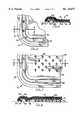
- FIG. 3is an enlarged fragmentary sectional view taken substantially along the line and in the direction of the arrows 3--3 of FIG. 1;
- FIG. 4is a perspective view of the mat illustrating the pliable nature of the mat
- FIG. 5is a fragmentary bottom plan view of an alternative embodiment of a floor mat in accordance with the present invention.
- FIG. 6is an enlarged fragmentary sectional view taken substantially along the line and in the direction of the arrows 6--6 of FIG. 5;
- FIG. 7is a fragmentary bottom plan view of a floor mat in accordance with the present invention.
- FIG. 8is a fragmentary sectional view taken substantially along the line and in the direction of the arrows 8--8 of FIG. 7;
- FIG. 9is a fragmentary sectional view illustrating another embodiment of the invention.
- FIG. 10is a top perspective view of a household floor mat in accordance with the invention.
- FIG. 11is a bottom perspective view of the floor mat shown in FIG. 10.
- the pliable multilayer floor mat of the present inventionis indicated generally by the numeral 10.
- the term "pliable”relates to the mat being easily folded or flexed and is illustrated in FIG. 4.
- the floor matincludes an upper face layer 12 overlying a base layer 15 the base layer 15 having an upper surface 17 and a bottom surface 19.
- the bottom surface 19is adapted to confront flooring overlaid by the mat.
- the base layer 15further includes a relatively thin main body section 20 bordered by a relatively thick edge section 21 as compared to each other.
- the edge section 21 of the base layer 15has a channel 22 extending longitudinally thereof, and preferably opens from the bottom surface 19 of the base layer 15.
- the upper face layer 12preferably is formed from carpet material which is wear-resistant and has a pleasing appearance.
- the face layercan be an elastomer layer 12a (FIG. 9), a thermoplastic layer, such as a vinyl compound, or a non-woven layer.
- the carpet materialmay be tufted, woven, needle punched or the like, and may be backed or unbacked.
- the carpet materialis a tufted pile carpet construction, i.e., a plurality of pile yarns extend through a primary backing to form loops which are cut to form tufts.
- the fibers of the pile yarnscan be composed of natural or synthetic fibers and may be thermoplastic or thermosetting.
- carpet fibers employed in the present inventionare described in U.S. Pat. No. 4,174,991 to Reuben, the disclosure of which is incorporated herein by reference as if set out fully, and include polyamide fibers such as nylon fibers, particularly nylon 6 and nylon 66, polyester fibers, acrylic fibers, polypropylene and blends and copolymers thereof.
- the base layer 15is preferably formed of a heat curable elastomeric material or a thermoplastic material.
- Exemplary heat curable elastomeric materialsinclude vulcanizable elastomers which are cured by a sulfur reaction mechanism or a metallic oxide mechanism.
- Particularly suitable elastomeric materialsare rubbers such as natural rubber, butadiene polymers and copolymers such as styrene-butadiene rubbers and polybutadiene rubbers, isoprene polymers and copolymers, chloroprene rubbers such as neoprene, nitrile rubbers, butyl rubbers, and ethylene-propylene rubbers, and blends and copolymers thereof.
- Styrene-butadiene rubbersare particularly preferred for use in the present invention.
- Suitable thermoplastic materialsinclude polyvinyl chloride, polyethylene, ethylene vinyl acetate, polypropylene, polystyrene, and thermoplastic rubber.
- the channel 22circumscribes the periphery of the floor mat 10.
- the upper surface 23 of edge section 21is disposed at an elevation above the elevation of the main body section 20.
- this elevated upper surface 23 of the base layer 15provides a decorative and aesthetically pleasing edge portion 24 to the face layer 12 of the floor mat 10, and eliminates the need for stitching or binding of the edge of the mat.
- the elevated upper surface 23 of edge section 21reduces the tendency of the uppermost face layer 12 to separate from the base layer 15.
- the decorative edge portion 24 of the face layer 12is preferably about 1/4 inches high, but heights from about 1/8 to about 1/2 inches may be used.
- the channel 22is formed in and preferably opens from the bottom surface 19 of the base layer 15.
- the channel 22assists in creating the thicker edge section 21 of the base layer 15.
- a thicker edge section 21 of the floor matmay optionally result from the redistribution of base layer material during the molding, particularly compression molding of the floor mat. This thicker edge section 21 also prevents the mat 10 from slipping during use.
- the shape of the channel 22is shown as substantially rectangular in FIGS. 1-8 and as a tapered channel in FIG. 9, but may be of other shapes such as V-shaped or U-shaped or semicircular.
- the channel 20is preferably about 1/4 inches wide and about 1/4 inches deep, however, suitable dimensions for the channel are typically from about 1/8 to about 1/2 inches wide and from about 1/8 to about 1/2 inches deep.
- the bottom surfaces of the main body portion 20 and the edge section 21 of the base layer 15are, as shown in FIGS. 3 and 6, substantially coplanar.
- the bottom surface 19 of the base layer 15 which extends outward from the channel 22 to the edge of the floor mat 10 and the bottom surface 15 of the base layer 15 which extends inward from the channel 20both are closely adjacent and preferably underlying surface of the flooring.
- the present inventionmay optionally have a step portion 27 extending from the outer edge of the thicker edge section 21 of the base layer 15.
- the width of the step portion 27is preferably less than one inch and more preferably greater than 1/16 inch.
- the step portion 27 of the floor matextends outward from the edge section 21 to the edge of the floor mat 10, and during use the bottom surface of the step portion 27 is substantially coplanar with the portion of the bottom surface 19 of the base layer 15.
- the step portion 27adds area for bonding of the face layer 12 to the base layer 15 thereby increasing the strength of the bond between the layers and increasing the resistance to separation.
- the step portion 27provides a smooth edge to the floor mat 10 without the use of binding materials by allowing for the return from the edge section 21 of the base layer 15 to the normal thickness of the base layer 15 and thereby exposing a limited portion of the base layer 15 to view.
- rib members 30are disposed in and extend transversely across the channel 22, strengthen the channel 22 and prevent distortion of its shape.
- the rib members 30assist in reducing the tendency of the channel 22 of compressing or spreading add causing the edges of the mat 3O to elevate above the surface upon which the mat is placed.
- the elevation of the edges of the mat 10 above the surface upon which the mat is placedincreases the possibility of wear, can present an impediment to ingress and egress of a vehicle or dwelling and can contribute to mat slippage during use.
- the rib members 30are shown as spaced approximately one inch apart however, spacings from about 1/2 to about 2 inches may be used.
- the floor mat 10preferably includes a plurality of nib elements 32 and/or other anti-slippage anchoring means such as the material 35 shown in FIG. 7.
- the nib elementsillustratively and preferably are of frusto-conical shape and are connected to the lower surface of base layer 15.
- the nib elements 32extend substantially vertically downward from the base layer 15 and when provided through the material 35 upon the bottom surface of the base layer 15.
- the material 35may be a tacky pressure-sensitive adhesive material as described in U.S. application Ser. No. 07/642,926 filed Jan. 18, 1991, or polyurethane foam as described in U.S. application Ser. No. 07/687,234 filed Apr. 18, 1991, the disclosures of which are incorporated herein by reference as if set out fully.
- the main body section 20 of the floor mat 10can also have a channel 22a formed in a portion thereof, and preferably opening from a bottom surface 19a of the main body section
- the upper surface 23a of the portion of the main body section 20 having the channel 22ais disposed at an elevation above the elevation of the remainder of the main body section 20 and is substantially the same elevation as the upper surface 23 of edge section
- this elevated upper surface 23a of the main body section 20provides a decorative and aesthetically pleasing design in the main body section 20, for example, the umbrella shown in FIGS. 10 and 11 or indicia of an automobile manufacturer.
- the method of the present inventionincludes contacting the upper or top surface 17 of a base layer 15 to the bottom surface of the upper face layer 12 followed by placing the base layer 15 and face layer 12 under compressive molding pressure, (e.g., a pressure selected from the range of 50 psi to about 250 psi).
- compressive molding pressuree.g., a pressure selected from the range of 50 psi to about 250 psi.
- a channel 22 or channel 22ais molded in, and preferably opens from the bottom surface 19 of the base layer 15 or the bottom surface 19a of the main body portion 20 while the upper face layer 12 and base layer 15 are under compressive molding pressure.
- a portion of the bottom surface of the face layer 12becomes embedded in the base layer during heating and curing of the base layer 15 at a temperature of from about 250° F. to about 400° C. while the carpet and base layer are under the compressive molding pressure.
- the face layer of the multilayered mat 10is cooled to a temperature of less than 100° F. to maintain the fibers of the carpet yarns below a temperature at which the pile become substantially permanently deformed under the applied molding pressure and so as to maintain the resiliency of the face layer 12 upon release of the molding pressure.
- the coolingis conducted simultaneously while the face layer 12 and base layer 15 are under pressure.
- the heating of the base layer 15is maintained until the elastomeric material or the thermoplastic material of the base layer are cured.
- a suitable molding apparatusis described more fully in U.S. Pat. No. 4,174,991, although other molding techniques, particularly if thermoplastic materials are used, will be apparent to one skilled in the art.
- a sufficient compressive molding pressuremust be employed in the present invention to achieve a bond between the bottom surface of the face layer 12 and the upper surface 17 of the base layer 15.
- Sufficient compressive molding pressureis also required to mold the base layer material into the recess in the mold cavity.
- sufficient molding pressuremust be employed in order to embed the loops of a tufted pile carpet face layer 12 into the base layer 15 and also to insure that the elastomeric base layer 15 is formed into the desired channel 22.
- sufficient pressuremay be required to cause the flow of the base layer material when forming the channel 22 and to form the relatively thick edge section 21 adjacent the periphery of the floor mat 10.
- a mat in accordance with the present inventioncan be used upon various flooring having carpeted areas or hard surface areas or both types of areas, such as in automobiles and in households. Additionally, the mat will have a longer useful life and can be used more successfully under wet or dirty conditions than a mat having only conventional anchoring means.
Landscapes
- Engineering & Computer Science (AREA)
- Mechanical Engineering (AREA)
- Transportation (AREA)
- Carpets (AREA)
- Laminated Bodies (AREA)
- Passenger Equipment (AREA)
Abstract
Description
Claims (18)
Priority Applications (1)
| Application Number | Priority Date | Filing Date | Title |
|---|---|---|---|
| US09/163,995USRE36677E (en) | 1991-05-03 | 1998-09-30 | Method of making a floor mat having a channel |
Applications Claiming Priority (4)
| Application Number | Priority Date | Filing Date | Title |
|---|---|---|---|
| US07/694,966US5154961A (en) | 1991-05-03 | 1991-05-03 | Floor mat and method of making same |
| US07/872,456US5362544A (en) | 1991-05-03 | 1992-04-23 | Floor mat and method of making same |
| US08/248,522US5620546A (en) | 1991-05-03 | 1994-05-24 | Method of making a floor mat having a channel |
| US09/163,995USRE36677E (en) | 1991-05-03 | 1998-09-30 | Method of making a floor mat having a channel |
Related Parent Applications (2)
| Application Number | Title | Priority Date | Filing Date |
|---|---|---|---|
| US07/872,456DivisionUS5362544A (en) | 1991-05-03 | 1992-04-23 | Floor mat and method of making same |
| US08/248,522ReissueUS5620546A (en) | 1991-05-03 | 1994-05-24 | Method of making a floor mat having a channel |
Publications (1)
| Publication Number | Publication Date |
|---|---|
| USRE36677Etrue USRE36677E (en) | 2000-05-02 |
Family
ID=24791023
Family Applications (3)
| Application Number | Title | Priority Date | Filing Date |
|---|---|---|---|
| US07/694,966Expired - LifetimeUS5154961A (en) | 1991-05-03 | 1991-05-03 | Floor mat and method of making same |
| US07/872,456Expired - LifetimeUS5362544A (en) | 1991-05-03 | 1992-04-23 | Floor mat and method of making same |
| US09/163,995Expired - LifetimeUSRE36677E (en) | 1991-05-03 | 1998-09-30 | Method of making a floor mat having a channel |
Family Applications Before (2)
| Application Number | Title | Priority Date | Filing Date |
|---|---|---|---|
| US07/694,966Expired - LifetimeUS5154961A (en) | 1991-05-03 | 1991-05-03 | Floor mat and method of making same |
| US07/872,456Expired - LifetimeUS5362544A (en) | 1991-05-03 | 1992-04-23 | Floor mat and method of making same |
Country Status (2)
| Country | Link |
|---|---|
| US (3) | US5154961A (en) |
| KR (1) | KR100254178B1 (en) |
Cited By (21)
| Publication number | Priority date | Publication date | Assignee | Title |
|---|---|---|---|---|
| US6382350B1 (en) | 2001-04-02 | 2002-05-07 | Collins & Aikman Products Corp. | Molded acoustic and decorative mats and methods for forming the same |
| US6595321B1 (en) | 2002-03-28 | 2003-07-22 | Collins & Aikman Products Co. | Floor mats having peripheral apertures with acoustic absorbing material |
| US20040091674A1 (en)* | 2002-11-12 | 2004-05-13 | 3M Innovative Properties Company | Mat with elastic compressible elements |
| US20040101652A1 (en)* | 2002-09-30 | 2004-05-27 | Parrish Kenneth R. | Hybrid vehicle interior component |
| FR2871101A1 (en)* | 2004-06-02 | 2005-12-09 | Renault Sas | CLADDING DEVICE FOR A MOTOR VEHICLE HABITACLE |
| US7011181B2 (en) | 2003-07-08 | 2006-03-14 | Lear Corporation | Sound insulation system |
| US20060092714A1 (en)* | 2004-10-29 | 2006-05-04 | Chang-Hyuk Lee | Semiconductor memory device with simplified data control signals |
| US20060162997A1 (en)* | 2005-01-27 | 2006-07-27 | Cooksey Timothy S | Acoustic mats and methods for making the same |
| FR2886235A1 (en)* | 2005-05-24 | 2006-12-01 | Fabrication D Accessoires De C | CARPET FLOOR ACCESSORY FOR MOTOR VEHICLE |
| US7182994B1 (en) | 2003-01-08 | 2007-02-27 | Pretty Products, Inc. | Acoustic floor mat |
| US20070077398A1 (en)* | 2005-10-04 | 2007-04-05 | Viam Manufacturing, Inc. | Plastically deformable mat |
| US20070187978A1 (en)* | 2006-02-15 | 2007-08-16 | Simons Matthew L W | Vehicle utility mat |
| US20090061148A1 (en)* | 2007-08-28 | 2009-03-05 | Seung Kwon Cha | Auxiliary mat for vehicle |
| US20090226661A1 (en)* | 2005-11-03 | 2009-09-10 | Yannick Laurent | Floor coverings and methods of making and using |
| US20110195219A1 (en)* | 2009-10-19 | 2011-08-11 | Jeneva Bell | Rugs with a mat portion |
| US20130146734A1 (en)* | 2011-06-09 | 2013-06-13 | Waxman Consumer Products Group Inc. | Protection stand |
| USD713654S1 (en)* | 2013-09-19 | 2014-09-23 | Edward S. Robbins, III | Molded anti-fatigue mat |
| USD743185S1 (en)* | 2014-02-05 | 2015-11-17 | Pet Fusion, Llc | Food mat |
| WO2020023338A1 (en)* | 2018-07-23 | 2020-01-30 | Cintas Corporate Services, Inc. | Deconstructed floor mat |
| US10786723B1 (en) | 2019-11-05 | 2020-09-29 | Kevin Loftus | Golf practice device, and method of practicing golf swings by hitting golf balls from replicated sloping topographical conditions, which include side-hill lies, up-hill lies, and/or down-hill lies, encountered on a golf course, off a simulated fairway and/or a simulated rough |
| US10882273B2 (en)* | 2016-01-05 | 2021-01-05 | Auria Solutions Uk I Ltd. | Extruded nib design for automotive floor mats |
Families Citing this family (68)
| Publication number | Priority date | Publication date | Assignee | Title |
|---|---|---|---|---|
| ES2151882T3 (en)* | 1991-05-03 | 2001-01-16 | Collins & Aikman Accessory Mat | SOIL CARPET AND PROCEDURE FOR MANUFACTURING. |
| US5154961A (en)* | 1991-05-03 | 1992-10-13 | The Akro Corporation | Floor mat and method of making same |
| USD353505S (en) | 1992-03-06 | 1994-12-20 | Rea Marty P L | Garage mat |
| US5474829A (en)* | 1994-01-24 | 1995-12-12 | Jps Automotive Products Corp. | Variable density motor vehicles carpet |
| US5605247A (en)* | 1995-09-29 | 1997-02-25 | Tidy Tot Inc. | Mat with removable receptacle |
| US5815995A (en)* | 1996-08-01 | 1998-10-06 | Diversified Industrial Technologies, Inc. | Slip-resistant floor covering system |
| ES1034961Y (en)* | 1996-08-26 | 1997-07-16 | Vilardell Marin Jaime | VEHICLE FLOOR MAT. |
| US5753336A (en)* | 1996-10-02 | 1998-05-19 | Stull; Thomas Emerson | Reversible underlay for rugs |
| US6277233B1 (en) | 1997-01-28 | 2001-08-21 | Pacific Foam Technologies | Customized cushioned floor mat and method of producing same |
| US5876825A (en)* | 1997-01-28 | 1999-03-02 | Pacific Foam Technologies | Customized cushioned floor mat and method of producing same |
| US5891546A (en)* | 1997-03-14 | 1999-04-06 | Sherman; Raymond O. | Auxiliary molded floor mats |
| US6237266B1 (en)* | 1997-07-11 | 2001-05-29 | Daniel J. Tassey | Evacuation route having photoluminescent indicators |
| EP0899154A3 (en) | 1997-08-29 | 2000-04-19 | Japan Vilene Company, Ltd. | Floor mat and process for producing the same |
| US6114014A (en)* | 1997-08-29 | 2000-09-05 | Japan Vilene Company, Ltd. | Floor mat and process for producing the same |
| US6022503A (en)* | 1997-09-08 | 2000-02-08 | Lear Corporation | Method of making floor mats |
| US6202390B1 (en) | 1997-09-19 | 2001-03-20 | Southpac Trust International, Inc. | Packaging process |
| US6401436B2 (en) | 1997-09-19 | 2002-06-11 | Southpac Trust International, Inc. | Packaging material |
| US6298637B1 (en) | 1997-09-19 | 2001-10-09 | Southpac Trust International, Inc. | Packaging material |
| USD404351S (en) | 1997-10-14 | 1999-01-19 | Kruk Matthew J | Non-slip vehicle mat |
| US6159576A (en)* | 1997-12-11 | 2000-12-12 | Milliken & Company | Floor mat solely comprised of monofilament nylon fiber and having an ozone resistant, non-staining rubber backing sheet |
| US20030024062A1 (en)* | 2000-06-22 | 2003-02-06 | Mckay William D. | Cleaning mat with a plurality of disposable sheets |
| WO2000019871A1 (en)* | 1998-10-05 | 2000-04-13 | Kleen-Tex Industries, Inc. | Track control floor mats and applications therefor |
| US6221298B1 (en) | 1998-11-17 | 2001-04-24 | International Specialty Products, Llc | Method and apparatus for manufacturing molded products |
| US6296733B1 (en)* | 1998-12-01 | 2001-10-02 | Lear Corporation | Floor mats and method of making same |
| US6238765B1 (en) | 1999-06-15 | 2001-05-29 | Racemark International, Inc. | Vehicle floor mat |
| US6554782B2 (en)* | 2001-01-22 | 2003-04-29 | Edward S. Robbins, III | Chairmat with foot massage area |
| US20020172803A1 (en)* | 2001-05-21 | 2002-11-21 | Delusky Arthur K. | Molded article and process for preparing same |
| USD481576S1 (en) | 2001-10-05 | 2003-11-04 | Robbins, Iii Edward S. | Cleated carpet-engaging surface |
| KR100472851B1 (en)* | 2002-04-04 | 2005-03-08 | 김상현 | Nc rubber mat |
| US20060151097A1 (en)* | 2005-01-13 | 2006-07-13 | Bennett Norman H | Method of making a non-carpeted floor covering |
| WO2006115482A2 (en)* | 2005-04-21 | 2006-11-02 | Foss Manufacturing Co., Inc. | Fire-retardant, lightweight aircraft carpet |
| US20070098952A1 (en)* | 2005-10-31 | 2007-05-03 | Blinstrub Robert M | Extruded laminated floor mat and method of manufacturing same |
| US20070193149A1 (en)* | 2006-01-25 | 2007-08-23 | Fan-Juo Chang | Floor pad |
| USD586601S1 (en) | 2006-07-24 | 2009-02-17 | Robbins Iii Edward S | Mud mat |
| KR100802031B1 (en) | 2007-03-26 | 2008-02-12 | 주식회사 제이엔티 | Automotive floor mats |
| US7987645B2 (en)* | 2007-03-29 | 2011-08-02 | Serious Materials, Inc. | Noise isolating underlayment |
| US20090212584A1 (en)* | 2008-02-21 | 2009-08-27 | Hill Dean E | Cargo management system |
| US20110024229A1 (en)* | 2008-08-19 | 2011-02-03 | Ming-Shun Yang | Sound Insulating and Absorbing Automotive Foot Mat Structure |
| JP4570675B2 (en)* | 2008-09-04 | 2010-10-27 | 株式会社ファルテック | floor mat |
| US8337340B2 (en)* | 2009-02-16 | 2012-12-25 | Sportsfield Specialties, Inc. | Bases, home plates, and pitcher's rubbers for use on synthetic turf infill material |
| USD666044S1 (en)* | 2010-05-27 | 2012-08-28 | Magnet Works, Ltd. | Frame for a modular anti-fatigue floor mat assembly |
| USD658917S1 (en)* | 2010-07-06 | 2012-05-08 | Bossiz Harris | Multi-purpose mat |
| PL2602096T3 (en)* | 2010-08-05 | 2014-05-30 | Butech Building Tech S A | Process for producing pieces of removable floor covering and removable floor covering |
| US8573677B2 (en) | 2010-09-13 | 2013-11-05 | Josef Dirnfeld | Floor mat and method for manufacturing a floor mat |
| US20120135182A1 (en)* | 2010-11-30 | 2012-05-31 | Yao Larry | Plastic thread door mat and a forming mold thereof |
| EP2537977B1 (en)* | 2011-06-21 | 2014-06-25 | Kleen-Tex Industries in Europa GmbH | Textile floor covering |
| US20130084427A1 (en)* | 2011-10-03 | 2013-04-04 | Randall Rob Ernst | Floor mat and methods |
| US20130171419A1 (en)* | 2011-11-04 | 2013-07-04 | Winfield Consumer Products, Inc. | Flexible custom floor mats |
| US10676004B2 (en)* | 2011-11-30 | 2020-06-09 | Thermoflex Corporation | Floor mat with isolated support members |
| CN103841858B (en)* | 2012-05-25 | 2015-08-19 | 卢向阳 | A kind of environmental protection is anti-skidding from skinning improvement ground cushion |
| USD735494S1 (en) | 2013-02-12 | 2015-08-04 | Allan Wendling | Shoe cleaning mat |
| GB2527730A (en)* | 2014-04-07 | 2016-01-06 | Mark Fletcher | Protective sheet |
| US9724581B2 (en)* | 2014-04-18 | 2017-08-08 | Lauren Tyndall | Pitching mat device |
| US9242160B2 (en)* | 2014-04-18 | 2016-01-26 | Lauren Tyndall | Pitching mat device |
| USD758761S1 (en)* | 2014-12-04 | 2016-06-14 | Kevin Chang | Mat |
| USD771973S1 (en) | 2015-01-08 | 2016-11-22 | Macneil Ip Llc | Mat |
| USD796227S1 (en)* | 2015-01-08 | 2017-09-05 | Macneil Ip Llc | Outdoor mat |
| US9861220B2 (en)* | 2015-03-04 | 2018-01-09 | John Charles BURKHALTER | Slidable anti-fatigue mat |
| US9944017B2 (en)* | 2016-05-12 | 2018-04-17 | R&L Marketing & Sales, Inc. | Ultrasonically welded mat unit and system thereof |
| AT518801A1 (en)* | 2016-06-24 | 2018-01-15 | Walser Man Gmbh | Method of making a car doormat |
| US9615661B1 (en) | 2016-08-09 | 2017-04-11 | Steven Hildebrand | Multi level rack apparatus having intersecting arms |
| JP6818490B2 (en)* | 2016-10-03 | 2021-01-20 | 西川ゴム工業株式会社 | Door hole sealant for automobiles |
| USD894072S1 (en)* | 2019-01-15 | 2020-08-25 | Guy N. Dougherty | Fuel collection and evaporation mat |
| USD1075357S1 (en) | 2022-06-01 | 2025-05-20 | Guy N. Dougherty | Rollable fuel collection and evaporation mat |
| USD1053774S1 (en) | 2022-06-01 | 2024-12-10 | Guy N. Dougherty | Weighted collection mat |
| USD1032126S1 (en)* | 2024-01-26 | 2024-06-18 | Xiejun Quan | Washer dryer top protector mat |
| USD1069286S1 (en)* | 2024-06-28 | 2025-04-01 | Dongguan Linaidou Trading Co., Ltd. | Top mat for washer and dryer |
| USD1060906S1 (en)* | 2024-08-23 | 2025-02-04 | Dongyang Xuyao Decorative Materials Trading Company | Laundry countertop |
Citations (41)
| Publication number | Priority date | Publication date | Assignee | Title |
|---|---|---|---|---|
| US1935302A (en)* | 1930-10-11 | 1933-11-14 | Waite Carpet Company | Patterned rug and method of making the same |
| US2296502A (en)* | 1939-10-16 | 1942-09-22 | Baldwin Rubber Co | Method of manufacturing floor mats |
| US2939179A (en)* | 1957-06-21 | 1960-06-07 | Magee Carpet Co | Method of molding a carpet |
| US3014829A (en)* | 1958-06-24 | 1961-12-26 | Curtin Ernest | Adhesived carpet blocks |
| US3703424A (en)* | 1968-07-30 | 1972-11-21 | Dunlop Holdings Ltd | Method of producing a wear-resistant area in a surface-covering material |
| GB1325203A (en)* | 1970-09-05 | 1973-08-01 | Dunlop Holdings Ltd | Floor coverings |
| US3804699A (en)* | 1971-06-25 | 1974-04-16 | Ludlow Corp | Slip-resistant mat |
| US3821065A (en)* | 1972-04-06 | 1974-06-28 | Sackner Prod Inc | Foam-fibrous pad |
| US3953631A (en)* | 1974-09-04 | 1976-04-27 | Deering Milliken Research Corporation | Dust collection mats |
| DE2619361A1 (en)* | 1976-04-30 | 1977-11-10 | Walter Kempe | Antislip mat for carpets including plastics grid - has groups of short points on its upper surface with long points on underside |
| US4143194A (en)* | 1977-03-01 | 1979-03-06 | Arbrook, Inc. | Disposable floor mat combination |
| US4174991A (en)* | 1978-11-13 | 1979-11-20 | The Akro Corporation | Process of laminating carpet to elastomeric backing |
| US4230755A (en)* | 1976-11-23 | 1980-10-28 | C. H. Masland & Sons | Moldable unitary composite carpet structure |
| US4361614A (en)* | 1981-05-20 | 1982-11-30 | Moffitt Jr Merritt L | Slip resistant mat with molding and method of assembly |
| US4382986A (en)* | 1982-02-09 | 1983-05-10 | The Akro Corporation | Automobile floor mat with two base portions of different elastomeric materials |
| US4399176A (en)* | 1980-03-31 | 1983-08-16 | Pretty Products, Inc. | Automotive floor mat having rigid rib |
| JPS5914813A (en)* | 1982-07-19 | 1984-01-25 | 池内 唯 | Production of carpet mat |
| US4465720A (en)* | 1981-11-06 | 1984-08-14 | Pretty Products, Inc. | Automotive floor mat having rigidifying sheet-form element |
| US4529639A (en)* | 1984-06-27 | 1985-07-16 | Collins & Aikman Corporation | Molded foam-backed carpet assembly and method of producing same |
| US4579764A (en)* | 1984-06-27 | 1986-04-01 | Collins & Aikman Corporation | Molded carpet assembly with sound deadening foam backing |
| US4609580A (en)* | 1985-01-07 | 1986-09-02 | Kimberly-Clark Corporation | Absorbent floor mat |
| GB2171901A (en)* | 1985-03-08 | 1986-09-10 | Cannon Rubber Ltd | Vehicle floor mat |
| WO1986006691A1 (en)* | 1985-05-03 | 1986-11-20 | Bob Bailey | Auto accessory floor mat |
| US4673603A (en)* | 1980-03-17 | 1987-06-16 | The 2500 Corporation | Floor mat mounting system |
| EP0259795A2 (en)* | 1986-09-09 | 1988-03-16 | Friedrich Hüther | Mat, especially floor mat for motor vehicles, consisting of textile |
| US4733997A (en)* | 1985-06-18 | 1988-03-29 | Tenex Corporation | Method of producing chair mats and the like involving edge trimming |
| US4748063A (en)* | 1987-09-21 | 1988-05-31 | The Akro Corporation | Automotive floor covering with pad attachment means |
| US4749602A (en)* | 1987-04-17 | 1988-06-07 | Russell Elaine T | Lambswool heel saver mat |
| US4751764A (en)* | 1985-08-19 | 1988-06-21 | The Akro Corporation | Floor mat anchor |
| US4758457A (en)* | 1987-02-24 | 1988-07-19 | The 2500 Corporation | Floor mat with integral retainer means |
| US4828898A (en)* | 1985-05-03 | 1989-05-09 | Bob Bailey | Auto accessory floor mat |
| US4835030A (en)* | 1987-10-14 | 1989-05-30 | C. H. Masland & Sons | In situ pattern molding and adhesion of PVC heel pad blanks to automotive carpeting without dielectric means |
| JPH01223909A (en)* | 1988-03-02 | 1989-09-07 | Kazuo Ushijima | Mat and manufacture of it |
| EP0351041A2 (en)* | 1988-07-11 | 1990-01-17 | Milliken Research Corporation | Dust control mat with non-cleated borders |
| US4938677A (en)* | 1987-02-24 | 1990-07-03 | Robbins Edward S Iii | Pattern rolls useful for the in-line contoured edge molding of extruded plastic products |
| US4973505A (en)* | 1989-05-30 | 1990-11-27 | William Bielous | Reversible mat |
| USD313789S (en) | 1988-07-11 | 1991-01-15 | Kraco Enterprises, Inc. | Floor mat |
| US5071614A (en)* | 1990-06-25 | 1991-12-10 | Nifty Products, Inc. | Method of molding a carpet having deep well areas |
| US5128189A (en)* | 1989-08-18 | 1992-07-07 | Bartlett David H | Disposable mat with compressible ridge |
| US5154961A (en)* | 1991-05-03 | 1992-10-13 | The Akro Corporation | Floor mat and method of making same |
| US5171619A (en)* | 1991-04-18 | 1992-12-15 | The Akro Corporation | Floor mat and process of forming the same |
- 1991
- 1991-05-03USUS07/694,966patent/US5154961A/ennot_activeExpired - Lifetime
- 1992
- 1992-04-23USUS07/872,456patent/US5362544A/ennot_activeExpired - Lifetime
- 1992-05-04KRKR1019920007607Apatent/KR100254178B1/ennot_activeExpired - Fee Related
- 1998
- 1998-09-30USUS09/163,995patent/USRE36677E/ennot_activeExpired - Lifetime
Patent Citations (42)
| Publication number | Priority date | Publication date | Assignee | Title |
|---|---|---|---|---|
| US1935302A (en)* | 1930-10-11 | 1933-11-14 | Waite Carpet Company | Patterned rug and method of making the same |
| US2296502A (en)* | 1939-10-16 | 1942-09-22 | Baldwin Rubber Co | Method of manufacturing floor mats |
| US2939179A (en)* | 1957-06-21 | 1960-06-07 | Magee Carpet Co | Method of molding a carpet |
| US3014829A (en)* | 1958-06-24 | 1961-12-26 | Curtin Ernest | Adhesived carpet blocks |
| US3703424A (en)* | 1968-07-30 | 1972-11-21 | Dunlop Holdings Ltd | Method of producing a wear-resistant area in a surface-covering material |
| GB1325203A (en)* | 1970-09-05 | 1973-08-01 | Dunlop Holdings Ltd | Floor coverings |
| US3804699A (en)* | 1971-06-25 | 1974-04-16 | Ludlow Corp | Slip-resistant mat |
| US3821065A (en)* | 1972-04-06 | 1974-06-28 | Sackner Prod Inc | Foam-fibrous pad |
| US3953631A (en)* | 1974-09-04 | 1976-04-27 | Deering Milliken Research Corporation | Dust collection mats |
| DE2619361A1 (en)* | 1976-04-30 | 1977-11-10 | Walter Kempe | Antislip mat for carpets including plastics grid - has groups of short points on its upper surface with long points on underside |
| US4230755A (en)* | 1976-11-23 | 1980-10-28 | C. H. Masland & Sons | Moldable unitary composite carpet structure |
| US4143194A (en)* | 1977-03-01 | 1979-03-06 | Arbrook, Inc. | Disposable floor mat combination |
| US4174991A (en)* | 1978-11-13 | 1979-11-20 | The Akro Corporation | Process of laminating carpet to elastomeric backing |
| US4673603A (en)* | 1980-03-17 | 1987-06-16 | The 2500 Corporation | Floor mat mounting system |
| US4399176A (en)* | 1980-03-31 | 1983-08-16 | Pretty Products, Inc. | Automotive floor mat having rigid rib |
| US4361614A (en)* | 1981-05-20 | 1982-11-30 | Moffitt Jr Merritt L | Slip resistant mat with molding and method of assembly |
| US4465720A (en)* | 1981-11-06 | 1984-08-14 | Pretty Products, Inc. | Automotive floor mat having rigidifying sheet-form element |
| US4382986A (en)* | 1982-02-09 | 1983-05-10 | The Akro Corporation | Automobile floor mat with two base portions of different elastomeric materials |
| JPS5914813A (en)* | 1982-07-19 | 1984-01-25 | 池内 唯 | Production of carpet mat |
| US4529639A (en)* | 1984-06-27 | 1985-07-16 | Collins & Aikman Corporation | Molded foam-backed carpet assembly and method of producing same |
| US4579764A (en)* | 1984-06-27 | 1986-04-01 | Collins & Aikman Corporation | Molded carpet assembly with sound deadening foam backing |
| US4609580A (en)* | 1985-01-07 | 1986-09-02 | Kimberly-Clark Corporation | Absorbent floor mat |
| GB2171901A (en)* | 1985-03-08 | 1986-09-10 | Cannon Rubber Ltd | Vehicle floor mat |
| US4721641A (en)* | 1985-05-03 | 1988-01-26 | Bob Bailey | Auto accessory floor mat |
| US4828898A (en)* | 1985-05-03 | 1989-05-09 | Bob Bailey | Auto accessory floor mat |
| WO1986006691A1 (en)* | 1985-05-03 | 1986-11-20 | Bob Bailey | Auto accessory floor mat |
| US4733997A (en)* | 1985-06-18 | 1988-03-29 | Tenex Corporation | Method of producing chair mats and the like involving edge trimming |
| US4751764A (en)* | 1985-08-19 | 1988-06-21 | The Akro Corporation | Floor mat anchor |
| EP0259795A2 (en)* | 1986-09-09 | 1988-03-16 | Friedrich Hüther | Mat, especially floor mat for motor vehicles, consisting of textile |
| US4938677A (en)* | 1987-02-24 | 1990-07-03 | Robbins Edward S Iii | Pattern rolls useful for the in-line contoured edge molding of extruded plastic products |
| US4758457A (en)* | 1987-02-24 | 1988-07-19 | The 2500 Corporation | Floor mat with integral retainer means |
| US4749602A (en)* | 1987-04-17 | 1988-06-07 | Russell Elaine T | Lambswool heel saver mat |
| US4748063A (en)* | 1987-09-21 | 1988-05-31 | The Akro Corporation | Automotive floor covering with pad attachment means |
| US4835030A (en)* | 1987-10-14 | 1989-05-30 | C. H. Masland & Sons | In situ pattern molding and adhesion of PVC heel pad blanks to automotive carpeting without dielectric means |
| JPH01223909A (en)* | 1988-03-02 | 1989-09-07 | Kazuo Ushijima | Mat and manufacture of it |
| EP0351041A2 (en)* | 1988-07-11 | 1990-01-17 | Milliken Research Corporation | Dust control mat with non-cleated borders |
| USD313789S (en) | 1988-07-11 | 1991-01-15 | Kraco Enterprises, Inc. | Floor mat |
| US4973505A (en)* | 1989-05-30 | 1990-11-27 | William Bielous | Reversible mat |
| US5128189A (en)* | 1989-08-18 | 1992-07-07 | Bartlett David H | Disposable mat with compressible ridge |
| US5071614A (en)* | 1990-06-25 | 1991-12-10 | Nifty Products, Inc. | Method of molding a carpet having deep well areas |
| US5171619A (en)* | 1991-04-18 | 1992-12-15 | The Akro Corporation | Floor mat and process of forming the same |
| US5154961A (en)* | 1991-05-03 | 1992-10-13 | The Akro Corporation | Floor mat and method of making same |
Non-Patent Citations (26)
| Title |
|---|
| "Presentation of Publications and Others", Japanese Patent Application No. 4-112,833 w/out attachments, dated Apr. 12, 1999. |
| Answer to the Official Action, re: EPO Application No. 92 401 240.4, dtd. Mar. 27, 1998; from A Hurwic et al.* |
| Communication including European Search Report (for EP 92 40 1240), dtd. Aug. 3, 1993; Examiner: L. Vistisen.* |
| Communication Pursuant to Article 96(2) and Rule 51(2) EPC re Application No. 92401240.4 2303, dtd. Dec. 2, 1997; Examiner: B. Novelli.* |
| Communication Pursuant to Article 96(2) and Rule 51(2) EPC re Application No. 92401240.4 2303, dtd. Feb. 13, 1997; Examiner: B. Novelli.* |
| Communication Pursuant to Article 96(2) and Rule 51(2) EPC re Application No. 92401240.4 2303, dtd. Jun. 9, 1995; Examiner: B. Novelli.* |
| Communication Pursuant to Article 96(2) and Rule 51(2) EPC re Application No. 92401240.4 2303, dtd. May 28, 1996; Examiner: B. Novelli.* |
| Communication Pursuant to Article 96(2) and Rule 51(2) EPC re Application No. 92401240.4-2303, dtd. Dec. 2, 1997; Examiner: B. Novelli. |
| Communication Pursuant to Article 96(2) and Rule 51(2) EPC re Application No. 92401240.4-2303, dtd. Feb. 13, 1997; Examiner: B. Novelli. |
| Communication Pursuant to Article 96(2) and Rule 51(2) EPC re Application No. 92401240.4-2303, dtd. Jun. 9, 1995; Examiner: B. Novelli. |
| Communication Pursuant to Article 96(2) and Rule 51(2) EPC re Application No. 92401240.4-2303, dtd. May 28, 1996; Examiner: B. Novelli. |
| English Translation of "Presentation of Publications and Others", Japanese Patent Application No. 4-112,833, dated Apr. 12, 1999. |
| English Translation of Presentation of Publications and Others , Japanese Patent Application No. 4 112,833, dated Apr. 12, 1999.* |
| J.C. Whitney Catalog No. 515J, p. 96, MAT No. 1 of 4 Piece Carpet Mat Set. Bottom Center of Page.* |
| J.C. Whitney Catalog No. 515T, p. 97, Plush Carpet Mat No. 1, Lower Left Center of Page and Customer tailored Carpet Mat No. 3. Left Center of Page.* |
| J.C. Whitney Catalog No. 515T, p. 97, Plush Carpet Mat No. 1, Lower Left Center of Page and Customer-tailored Carpet Mat No. 3. Left Center of Page. |
| Letter from Ronald J. Snyder to F. Michael Sajovec dated Dec. 20, 1996 (including 6 sheets of color photographs).* |
| Letter from Thomas M. Berry to Mr. James Lockwood dated Dec. 15, 1997.* |
| Memo from Kathy Au to Mr. Ernie De La Motte dated Jan. 23, 1993.* |
| Observations and Answer to Official Action, re: EPO Application No. 92 401 240.4, dtd. Oct. 5, 1995; from A. Hurwic et al.* |
| Observations and Answer to the Official Action, re: EPO Application No. 92 401 240.4, dtd. May 21, 1997; from A Hurwic et al.* |
| Observations and Answer to the Official Action, re: EPO Application No. 92 401 240.4, dtd. Nov. 13, 1996; from A Hurwic et al.* |
| Observations Based on Further Submission of Prior Art with Appendices and letter of B. Cronin, dtd. May 15, 1998, re: EPO Application No. EP 92401240.4.* |
| Presentation of Publications and Others , Japanese Patent Application No. 4 112,833 w/out attachments, dated Apr. 12, 1999.* |
| Submission of Additional Prior Art with Appendices and including letter of B. Cronin, dtd. Jul. 15, 1997; re: Application No. 92401240.4* |
| Untitled photographs of rubber mat (6 sheets, 11 photographs, labeled with reference No. 49), date unknown.* |
Cited By (29)
| Publication number | Priority date | Publication date | Assignee | Title |
|---|---|---|---|---|
| US6382350B1 (en) | 2001-04-02 | 2002-05-07 | Collins & Aikman Products Corp. | Molded acoustic and decorative mats and methods for forming the same |
| US6595321B1 (en) | 2002-03-28 | 2003-07-22 | Collins & Aikman Products Co. | Floor mats having peripheral apertures with acoustic absorbing material |
| US20040101652A1 (en)* | 2002-09-30 | 2004-05-27 | Parrish Kenneth R. | Hybrid vehicle interior component |
| US6986547B2 (en)* | 2002-09-30 | 2006-01-17 | Lear Corporation | Hybrid vehicle interior component |
| US20040091674A1 (en)* | 2002-11-12 | 2004-05-13 | 3M Innovative Properties Company | Mat with elastic compressible elements |
| US7182994B1 (en) | 2003-01-08 | 2007-02-27 | Pretty Products, Inc. | Acoustic floor mat |
| US20060151239A1 (en)* | 2003-07-08 | 2006-07-13 | Albin Donald C Jr | Sound insulation system |
| US7182172B2 (en)* | 2003-07-08 | 2007-02-27 | Lear Corporation | Sound insulation system |
| US7011181B2 (en) | 2003-07-08 | 2006-03-14 | Lear Corporation | Sound insulation system |
| FR2871101A1 (en)* | 2004-06-02 | 2005-12-09 | Renault Sas | CLADDING DEVICE FOR A MOTOR VEHICLE HABITACLE |
| US20060092714A1 (en)* | 2004-10-29 | 2006-05-04 | Chang-Hyuk Lee | Semiconductor memory device with simplified data control signals |
| US7464791B2 (en)* | 2005-01-27 | 2008-12-16 | Pretty Products, Llc | Acoustic mats and methods for making the same |
| US20060162997A1 (en)* | 2005-01-27 | 2006-07-27 | Cooksey Timothy S | Acoustic mats and methods for making the same |
| FR2886235A1 (en)* | 2005-05-24 | 2006-12-01 | Fabrication D Accessoires De C | CARPET FLOOR ACCESSORY FOR MOTOR VEHICLE |
| US20070077398A1 (en)* | 2005-10-04 | 2007-04-05 | Viam Manufacturing, Inc. | Plastically deformable mat |
| US20090226661A1 (en)* | 2005-11-03 | 2009-09-10 | Yannick Laurent | Floor coverings and methods of making and using |
| US20070187978A1 (en)* | 2006-02-15 | 2007-08-16 | Simons Matthew L W | Vehicle utility mat |
| US7261361B1 (en)* | 2006-02-15 | 2007-08-28 | Simons Matthew L W | Vehicle utility mat |
| US20090061148A1 (en)* | 2007-08-28 | 2009-03-05 | Seung Kwon Cha | Auxiliary mat for vehicle |
| US20110195219A1 (en)* | 2009-10-19 | 2011-08-11 | Jeneva Bell | Rugs with a mat portion |
| US8309198B2 (en) | 2009-10-19 | 2012-11-13 | Product Bliss, Llc | Rugs with a mat portion |
| US20130146734A1 (en)* | 2011-06-09 | 2013-06-13 | Waxman Consumer Products Group Inc. | Protection stand |
| US8844889B2 (en)* | 2011-06-09 | 2014-09-30 | Waxman Consumer Products Group Inc. | Protection stand |
| USD713654S1 (en)* | 2013-09-19 | 2014-09-23 | Edward S. Robbins, III | Molded anti-fatigue mat |
| USD743185S1 (en)* | 2014-02-05 | 2015-11-17 | Pet Fusion, Llc | Food mat |
| US10882273B2 (en)* | 2016-01-05 | 2021-01-05 | Auria Solutions Uk I Ltd. | Extruded nib design for automotive floor mats |
| WO2020023338A1 (en)* | 2018-07-23 | 2020-01-30 | Cintas Corporate Services, Inc. | Deconstructed floor mat |
| US11453195B2 (en) | 2018-07-23 | 2022-09-27 | Cintas Corporate Services, Inc. | Deconstructed floor mat |
| US10786723B1 (en) | 2019-11-05 | 2020-09-29 | Kevin Loftus | Golf practice device, and method of practicing golf swings by hitting golf balls from replicated sloping topographical conditions, which include side-hill lies, up-hill lies, and/or down-hill lies, encountered on a golf course, off a simulated fairway and/or a simulated rough |
Also Published As
| Publication number | Publication date |
|---|---|
| US5362544A (en) | 1994-11-08 |
| KR100254178B1 (en) | 2000-06-01 |
| KR920021096A (en) | 1992-12-18 |
| US5154961A (en) | 1992-10-13 |
Similar Documents
| Publication | Publication Date | Title |
|---|---|---|
| USRE36677E (en) | Method of making a floor mat having a channel | |
| US5620546A (en) | Method of making a floor mat having a channel | |
| US5171619A (en) | Floor mat and process of forming the same | |
| EP0220305B1 (en) | Auto accessory floor mat | |
| US7329451B2 (en) | Vehicle floor mats having integral hook retention | |
| US4382986A (en) | Automobile floor mat with two base portions of different elastomeric materials | |
| EP1189785B1 (en) | Surface covering, mold, and method of forming the same | |
| US5034258A (en) | Carpet mat with improved gripping surface | |
| JP2004526620A (en) | Sound absorbing mat and method of forming the same | |
| JPH03501006A (en) | car accessories floor mats | |
| US4731275A (en) | Carpet assembly which resists lateral movement and process of producing the same | |
| US20190270397A1 (en) | Molded Lightweight Layered Floor Liner Construction | |
| US20110117312A1 (en) | Anti-skidding structure of automobile foot mat | |
| WO1997006029A1 (en) | Automotive floor mat retention system | |
| US6012261A (en) | Method of installing wall-to-wall carpet | |
| EP1804625B1 (en) | Anti-slip lining | |
| JP3038465U (en) | Heel pad for floor mat and combination of floor mat and heel pad | |
| EP1731361A2 (en) | Anti-slip floor mat | |
| CA2688840A1 (en) | Anti-skidding structure of automobile foot mat | |
| US20030143367A1 (en) | Protective and/or decorative mat for equipping a motor vehicle | |
| JP2975299B2 (en) | Laying Carpet Mat Laying Structure | |
| JP2804432B2 (en) | Mat | |
| TW201114628A (en) | Skidproof structure of vehicle floor mat | |
| JPS63213Y2 (en) | ||
| WO1996041716A1 (en) | A selectively attachable floor covering and method of making the same |
Legal Events
| Date | Code | Title | Description |
|---|---|---|---|
| AS | Assignment | Owner name:COLLINS & AIKMAN ACCESSORY MATS, INC., OHIO Free format text:CHANGE OF NAME;ASSIGNOR:AKRO CORPORATION, THE;REEL/FRAME:010525/0565 Effective date:19990423 | |
| FPAY | Fee payment | Year of fee payment:4 | |
| AS | Assignment | Owner name:CHASE MANHATTAN BANK, AS COLLATERAL AGENT, THE, TE Free format text:GUARANTEE AND COLLATERAL AGREEMENT;ASSIGNOR:COLLINS & AIKMAN ACCESSORY MATS, INC.;REEL/FRAME:011828/0511 Effective date:20010223 | |
| AS | Assignment | Owner name:COLLINS & AIKMAN ACCESSORY MATS, INC., MICHIGAN Free format text:TERMINATION AND RELEASE OF SECURITY INTEREST IN PATENTS RECORDED AT REEL/FRAME 11828/0511;ASSIGNOR:JPMORGAN CHASE BANK (F/K/A THE CHASE MANHATTAN BANK);REEL/FRAME:012513/0441 Effective date:20020110 | |
| AS | Assignment | Owner name:JPMORGAN CHASE BANK, AS COLLATERAL AGENT, TEXAS Free format text:SECURITY INTEREST;ASSIGNOR:COLLINS & AIKMAN ACCESSORY MATS, INC. (DE CORPORATION);REEL/FRAME:012691/0720 Effective date:20011220 | |
| FPAY | Fee payment | Year of fee payment:8 | |
| AS | Assignment | Owner name:COLLINS & AIKMAN ACCESSORY MATS, LLC, MICHIGAN Free format text:CHANGE OF NAME;ASSIGNOR:COLLINS & AIKMAN ACCESSORY MATS, INC.;REEL/FRAME:020234/0196 Effective date:20070928 | |
| AS | Assignment | Owner name:INTERNATIONAL AUTOMOTIVE COMPONENTS GROUP NORTH AM Free format text:ASSIGNMENT OF ASSIGNORS INTEREST;ASSIGNOR:COLLINS & AIKMAN ACCESSORY MATS, LLC;REEL/FRAME:020299/0240 Effective date:20071011 | |
| FPAY | Fee payment | Year of fee payment:12 | |
| AS | Assignment | Owner name:GENERAL ELECTRIC CAPITAL CORPORATION, AS AGENT, CO Free format text:SECURITY INTEREST;ASSIGNOR:INTERNATIONAL AUTOMOTIVE COMPONENTS GROUP NORTH AMERICA, INC;REEL/FRAME:025845/0193 Effective date:20101110 Owner name:GENERAL ELECTRIC CAPITAL CORPORATION, AS AGENT, CO Free format text:SECURITY AGREEMENT;ASSIGNOR:INTERNATIONAL AUTOMOTIVE COMPONENTS GROUP NORTH AMERICA, INC.;REEL/FRAME:025882/0019 Effective date:20101110 | |
| XAS | Not any more in us assignment database | Free format text:SECURITY INTEREST;ASSIGNOR:INTERNATIONAL AUTOMOTIVE COMPONENTS GROUP NORTH AMERICA, INC;REEL/FRAME:025845/0193 | |
| AS | Assignment | Owner name:THE BANK OF NEW YORK MELLON, AS COLLATERAL AGENT, Free format text:SECURITY AGREEMENT;ASSIGNOR:INTERNATIONAL AUTOMOTIVE COMPONENTS GROUP NORTH AMERICA, INC., A DELAWARE CORPORATION;REEL/FRAME:026404/0069 Effective date:20110603 | |
| AS | Assignment | Owner name:CF LENDING, LLC , AS ADMINISTRATIVE AGENT, CONNECT Free format text:SECURITY INTEREST;ASSIGNOR:INTERNATIONAL AUTOMOTIVE COMPONENTS GROUP NORTH AMERICA, INC., AS GRANTOR;REEL/FRAME:036722/0440 Effective date:20150930 Owner name:CF LENDING, LLC , AS ADMINISTRATIVE AGENT, CONNECT Free format text:SECURITY INTEREST;ASSIGNOR:INTERNATIONAL AUTOMOTIVE COMPONENTS GROUP NORTH AMERICA, INC., AS GRANTOR;REEL/FRAME:036722/0294 Effective date:20150930 | |
| AS | Assignment | Owner name:THE BANK OF NEW YORK MELLON, AS COLLATERAL AGENT, Free format text:SECURITY AGREEMENT;ASSIGNOR:INTERNATIONAL AUTOMOTIVE COMPONENTS GROUP NORTH AMERICA, INC.;REEL/FRAME:036742/0576 Effective date:20150930 | |
| AS | Assignment | Owner name:INTERNATIONAL AUTOMOTIVE COMPONENTS GROUP NORTH AM Free format text:RELEASE BY SECURED PARTY;ASSIGNOR:GENERAL ELECTRIC CAPITAL CORPORATION, AS COLLATERAL AGENT;REEL/FRAME:036777/0904 Effective date:20150930 Owner name:INTERNATIONAL AUTOMOTIVE COMPONENTS GROUP NORTH AM Free format text:RELEASE BY SECURED PARTY;ASSIGNOR:THE BANK OF NEW YORK MELLON;REEL/FRAME:036777/0821 Effective date:20150930 | |
| AS | Assignment | Owner name:INTERNATIONAL AUTOMOTIVE COMPONENTS GROUP NORTH AM Free format text:RELEASE BY SECURED PARTY;ASSIGNOR:THE BANK OF NEW YORK MELLON;REEL/FRAME:043754/0606 Effective date:20170915 | |
| AS | Assignment | Owner name:INTERNATIONAL AUTOMOTIVE COMPONENTS GROUP NORTH AM Free format text:RELEASE BY SECURED PARTY;ASSIGNOR:WELLS FARGO BANK, NATIONAL ASSOCIATION;REEL/FRAME:044027/0776 Effective date:20170915 Owner name:INTERNATIONAL AUTOMOTIVE COMPONENTS GROUP NORTH AM Free format text:RELEASE BY SECURED PARTY;ASSIGNOR:WELLS FARGO BANK, NATIONAL ASSOCIATION;REEL/FRAME:044028/0309 Effective date:20170915 | |
| AS | Assignment | Owner name:AURIA SOLUTIONS UK I LTD., ENGLAND Free format text:ASSIGNMENT OF ASSIGNORS INTEREST;ASSIGNOR:INTERNATIONAL AUTOMOTIVE COMPONENTS GROUP NORTH AMERICA, INC.;REEL/FRAME:045222/0109 Effective date:20170915 |